DDSPAxx - DRFAxx - AA Opto Electronic
7
AA Sa reserves the right to make changes to the products or information herein without notice. No liability is assumed as a result of their use or application. AA Sa, 18, rue Nicolas Appert F-91898 ORSAY Tel: +33 (0)1 76 91 50 12 Fax: +33 (0)1 76 91 50 31 AA OPTO-ELECTRONIC – www.aaoptoelectronic.com DDSPAxx - DRFAxx VARIABLE FREQUENCY DRIVERS AA OPTO-ELECTRONIC proposes two types of variable frequency drivers. VCOs are analog devices and are suitable for general purpose applications (raster scan, or random access...). The VCO can be modulated (amplitude) from an analog external signal. The frequency is externally controlled by an analog signal. An external power amplifier will be required to generate the RF power levels required by the AO device. DDS models offer high frequency accuracy and stability and extremely fast switching times less than 100ns. They will be preferred to VCOs when high stability and accuracy is necessary. They can be modulated (amplitude) from an analog or digital external signal. The frequency is externally controlled by a digital signal (15 to 31 bits). An external power amplifier will be required to generate the RF power levels required by the AO device. DDSPAxx Based on DDS (Direct Digital Synthesizers) DDSPA - Product Overview These Direct Digital Synthesizers are dedicated to high accuracy applications for which high resolution is the key factor. A PC interface board will be used to control the frequency (15-31 bits) as well as the latch of the frequency (1 bit E/D). These drivers are used in combination with AA amplifiers. They are suitable for agile frequency shifters and deflectors. DDSPA - Features Variable frequency [20..400MHz] AM control: bits 8 digital 0-5V/ analog FM control: bits 15/23/31 digital Rack available with 2 outputs (XY deflection) DRFAxx Based on VCO (Voltage Controlled Oscillators) DRFA - Product Overview These Voltage Controlled Oscillators are the simplest way to control a deflector or a variable frequency shifter, in random access or raster scan mode. A voltage between 0 and 10V is applied on the frequency control input for sweeping between Fmin and Fmax and here the sweeping time can as low as 1μs. The typical stability of the VCO driver is 50 to 100 KHz/°C. For sharpest application, the DDS driver will be preferred. These drivers need to be associated with AA amplifiers (OEM version only). DRFA - Features Variable frequency: octave one to up AM control (Analog) FM control (Analog) Rack available with 2 outputs (XY deflection) RoHS Access to your operating manual TECHNICAL DATA SHEET 2014 DDS OEM version DDS Laboratory version – 1X DDS Laboratory version – 2X VCO OEM version VCO Laboratory version
Transcript of DDSPAxx - DRFAxx - AA Opto Electronic

AA Sa reserves the right to make changes to the products or information herein without notice. No liability is assumed as a result of their use or application. AA Sa, 18, rue Nicolas Appert F-91898 ORSAY Tel: +33 (0)1 76 91 50 12 Fax: +33 (0)1 76 91 50 31
AA OPTO-ELECTRONIC – www.aaoptoelectronic.com
DDSPAxx - DRFAxx VARIABLE FREQUENCY DRIVERS AA OPTO-ELECTRONIC proposes two types of variable frequency drivers. VCOs are analog devices and are suitable for general purpose applications (raster scan, or random access...). The VCO can be modulated (amplitude) from an analog external signal. The frequency is externally controlled by an analog signal. An external power amplifier will be required to generate the RF power levels required by the AO device. DDS models offer high frequency accuracy and stability and extremely fast switching times less than 100ns. They will be preferred to VCOs when high stability and accuracy is necessary. They can be modulated (amplitude) from an analog or digital external signal. The frequency is externally controlled by a digital signal (15 to 31 bits). An external power amplifier will be required to generate the RF power levels required by the AO device.
DDSPAxx Based on DDS (Direct Digital Synthesizers)
DDSPA - Product Overview These Direct Digital Synthesizers are dedicated to high accuracy applications for which high resolution is the key factor. A PC interface board will be used to control the frequency (15-31 bits) as well as the latch of the frequency (1 bit E/D). These drivers are used in combination with AA amplifiers. They are suitable for agile frequency shifters and deflectors. DDSPA - Features Variable frequency [20..400MHz] AM control:
bits 8 digital 0-5V/analog
FM control: bits 15/23/31 digital Rack available with 2 outputs (XY deflection )
DRFAxx Based on VCO (Voltage Controlled Oscillators)
DRFA - Product Overview These Voltage Controlled Oscillators are the simplest way to control a deflector or a variable frequency shifter, in random access or raster scan mode. A voltage between 0 and 10V is applied on the frequency control input for sweeping between Fmin and Fmax and here the sweeping time can as low as 1µs. The typical stability of the VCO driver is 50 to 100 KHz/°C. For sharpest application, the DDS driver will be preferred. These drivers need to be associated with AA amplifiers (OEM version only). DRFA - Features Variable frequency: octave one to up AM control (Analog) FM control (Analog) Rack available with 2 outputs (XY deflection) RoHS
Access to your operating manual
TE
CH
NIC
AL
DA
TA
SH
EE
T 2
01
4
DDS OEM version
DDS Laboratory version – 1X
DDS Laboratory version – 2X
VCO OEM version
VCO Laboratory version

AA Sa reserves the right to make changes to the products or information herein without notice. No liability is assumed as a result of their use or application. AA Sa, 18, rue Nicolas Appert F-91898 ORSAY Tel: +33 (0)1 76 91 50 12 Fax: +33 (0)1 76 91 50 31
AA OPTO-ELECTRONIC – www.aaoptoelectronic.com
Technical Specifications
Parameter DDSPAxx DRFAxx
Carrier frequency 10 to 400 MHz Up to one octave
(50-110, 60-150, 90-210, 150-300, 180-470) MHz Matched to AO device at factory
Frequency Stability Nom +/- 1 ppm/°C Nom +/- 50 to 100 kHz/°C
Frequency step / Accuracy LR: 15.259 KHz (15 bits) – MR: 59.6 Hz (23 bits)
HR: 0.23 Hz (31 bits) Continuous / typ 50 ppm
Commutation/sweeping time ≤ 40 ns (LR) - ≤ 64 ns (MR) - ≤ 80 ns (HR) ≤ 1µs (from Fmin to Fmax or Fmax to Fmin)
Output RF Power (@1dB compression)
Nom – 30 to 0 dBm (to be associated with AA Amplifier) Nom – 30 to 0 dBm (to be associated with AA Amplifier)
Power supply 24 VDC, nom 0.25A 24 VDC, nom 0.15A
Frequency Input Control Digital 15 bits (LR), 23 bits (MR), 31 bits (HR)
+ 1 bit Enable/disable Analog 0-10V/ 1k Ω (linearity Nom +/- 5 %)
Modulation Input Control Video In
Analog 0-5 V / 50 Ω Analog 0-5 V / 50 Ω
Rise Time / Fall time (10-90%) Nom 10 ns Nom 10 ns
Harmonics H2 > 30 dB, H3 > 20 dB Nom >20 dBc
Input / Output impedance 50 Ω 50 Ω
VSWR < 1.2/1 < 1.5/1
Extinction Ratio Nom 45 dB (for F<250MHz) nom 45 dB
Input / Output Connectors HD44 / SMA SMA / SMA
Size / Weight OEM: 129 x 61 x 28 mm3 (OEM) / 275 g
Lab version: 19”, 2U nom 4 Kgs (Lab version) OEM: 84 x 69 x 15.8 mm
3 / 150 g
Lab version: 310 x 250 x 105 mm3/ 3.8 Kg
Heat Exchange Conduction through baseplate for OEM versions Conduction through baseplate for OEM versions
Operating Temperature 10 to 40 (max Tcase 55°C) 10 to 40 (max Tcase 55°C)
Storage Temperature -40 to +50 Non condensing -40 to +50 Non condensing
DDSPAxx - Options / On request HIGH EXTINCTION RATIO 60dB
MOD IN 8 bits digital, 256 levels – Rise/fall time 25ns – DAC conversion time 100ns
LABORATORY VERSION complete turn key systems with minimum set up time.
POWER SUPPLY SIZE WEIGHT HEAT EXCHANGE
110-230 VAC 340x235x90 mm 3.6kg-3.8kg standalone (fan integrated) Build in amplifier 1, 2, 4…W
PHASE LOCKED Versions 2 DDS outputs with common Reference for high stability frequency difference
DRFAxx - Options / On request HIGH EXTINCTION RATIO 60dB
MOD IN 0-5 V/500 Ω
LABORATORY VERSION complete turn key systems with minimum set up time.
POWER SUPPLY SIZE WEIGHT HEAT EXCHANGE
110-230 VAC 310x250x105 mm 3.6kg-3.8kg standalone (fan integrated) Build in amplifier 1, 2, 4…W
NB: For laboratory version, the frequency source + the convenient amplifiers are integrated in a box supplied with 110-230 VAC. A switch on the front panel allows the user to select both operating modes:
- CW mode: internal CW modulation of RF power with front panel cursor - EXT mode: external amplitude modulation controlled through external modulation input

AA Sa reserves the right to make changes to the products or information herein without notice. No liability is assumed as a result of their use or application. AA Sa, 18, rue Nicolas Appert F-91898 ORSAY Tel: +33 (0)1 76 91 50 12 Fax: +33 (0)1 76 91 50 31
AA OPTO-ELECTRONIC – www.aaoptoelectronic.com
How to determine your DDS model
DDSPA XX – B 4 15b – 34 60
How to determine your VCO model
DRFA10Y 2X - B – 34 - 60.150
Number of Channels
• -- : 1 Channel
• 2X: 2 Channels
Power Supply
• B: OEM Version (24 VDC)
• D: Laboratory Version (110-230 VAC)
• 0: 1mW
• 30: 1W
• 34: 2.5 W
• 36: 4 W
Output RF power
Frequency range in MHz
• 60.150: 60 to 150 MHz
POWER SUPPLY
• B 24 VDC
• D 110-230 VAC
MAX RF POWER
• 0 1 mW
• 30 1 W
• 34 2.5 W
• 36 4 W
• 40 10 W
• 42 16 W
EXTINCTION RATIO
• -- 40 dB
• 60 60 dB
MODULATION INPUT AM Control
• 8b 8 bits
• 4 0-5 V
• 5 TTL
FREQUENCY CONTROL
• 15b 15 bits
• 23b 23 bits
• 31b 31 bits

AA Sa reserves the right to make changes to the products or information herein without notice. No liability is assumed as a result of their use or application. AA Sa, 18, rue Nicolas Appert F-91898 ORSAY Tel: +33 (0)1 76 91 50 12 Fax: +33 (0)1 76 91 50 31
AA OPTO-ELECTRONIC – www.aaoptoelectronic.com
Typ Relative Output RF power vs ANALOG MOD IN (0-5V)
0
0,2
0,4
0,6
0,8
1
1,2
1,4
0 0,5 1 1,5 2 2,5 3 3,5 4 4,5 5 5,5 6
MOD IN (V)
RF
Po
wer
/ P
0
Relative Output RF power vs DIGITAL MOD IN (TTL)
-0,2
0
0,2
0,4
0,6
0,8
1
1,2
0 0,5 1 1,5 2 2,5 3 3,5 4 4,5 5 5,5 6
MOD IN (V)
RF
Po
wer
/ P
0
Undefined level
for a VCO
DDS/VCO (analog MOD IN)
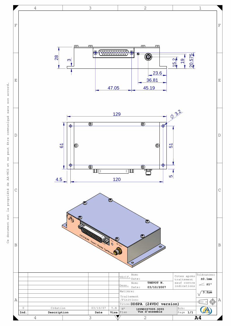
28
23.636.81
20.5
75
15.2 193
51
120
129
61
5
4.5
O3.2
03/10/070 T.NCréation
±0.1mm
3.2µm
THEVOT N.03/10/2007
±1°
1/1
DDSPA (24VDC version)
E
F
D
C
B
34 2 1
E
F
D
C
B
Ce document est la propriété de AA-MCS et ne peut être communiqué sans son accord.
A
Ind.
4Description
3Date Visa
2
N°Plan
Titre:
Traitement/Finition:
Matière:
Dess.
Vérif.Date:Nom:
Date:Nom:
PageEch:
Cotes aprèstraitementsauf contreindications
Tolérances:
A4
A
1SYNDI07005.0055Vue d'ensemble
45.1947.05

16/05/060 T.SCréation
±0.1mm
3.2µm
Saint-Jean T.16/05/2006
±1°
1/11/1
DRFA (24VDC version)
E
F
D
C
B
34 2 1
E
F
D
C
B
Ce document est la propriété de AA-MCS et ne peut être communiqué sans son accord.
A
Ind.
4Description
3Date Visa
2
N°Plan
Titre:
Traitement/Finition:
Matière:
Dess.
Vérif.Date:Nom:
Date:Nom:
PageEch:
Cotes aprèstraitementsauf contreindications
Tolérances:
A4
A
www.aa-mcs.com. Mail:[email protected]
15.8
7.3
37
7.3
37
22
843.2
77.6
59
69
O 3.5
5
16
16
1DRF006002.0055Plan d'ensemble

AA Sa reserves the right to make changes to the products or information herein without notice. No liability is assumed as a result of their use or application. AA Sa, 18, rue Nicolas Appert F-91898 ORSAY Tel: +33 (0)1 76 91 50 12 Fax: +33 (0)1 76 91 50 31
AA OPTO-ELECTRONIC – www.aaoptoelectronic.com
*Handles available on request
*Handles available on request
Version 1x Output RF power amplifier integrated inside Rack
Version 1x Output RF power amplifier integrated inside Rack