DDBC120-DALI · DALI to the DyNet network protocol eliminates DALI imposed limits, such as maximum...
4
DDBC120-DALI MultiMaster DALI Driver Controller Enabling a full DALI universe including tunable white drivers, DALI sensors and user interfaces The Philips Dynalite DDBC120-DALI delivers cost-effective control of DALI drivers through provision of a full universe of 64 DALI drivers. The device communicates seamlessly with Philips Dynalite DALI sensors and user interfaces. Signal Dimmers
Transcript of DDBC120-DALI · DALI to the DyNet network protocol eliminates DALI imposed limits, such as maximum...
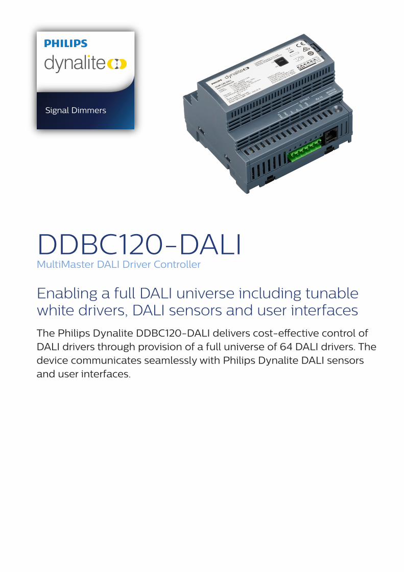
DDBC120-DALIMultiMaster DALI Driver Controller
Enabling a full DALI universe including tunable white drivers, DALI sensors and user interfaces
The Philips Dynalite DDBC120-DALI delivers cost-effective control of DALI drivers through provision of a full universe of 64 DALI drivers. The device communicates seamlessly with Philips Dynalite DALI sensors and user interfaces.
Signal Dimmers
2 DDBC120-DALI MultiMaster DALI Driver Controller Specification Sheet
• MultiMaster solution – Compatible with a range of DALI fittings and devices including DALI fluorescent drivers, DALI electronic low voltage transformers, DALI LED fixtures, DALI emergency lighting fixtures and Philips Dynalite DALI sensors and user interfaces.
• Compatible with DALI 209 drivers – Provides control of tunable white luminaires.
• DALI auto-enumeration – Provides automatic enumeration of DALI ballasts when powered on and enables self repair of the network system if a DALI driver fails.
• Fully scalable network solution – Direct mapping from DALI to the DyNet network protocol eliminates DALI imposed limits, such as maximum group sizes.
• Flexible mounting solution – A DIN-rail mountable device, designed to be installed into the distribution board supplying power to the controlled lighting circuit.
• Dual functionality – Leverage advantages of a true DALI network solution, whilst still allowing full function set of DyNet network control.
• Built-in energy savings – Control signals can be programmed to operate in tandem with the internal relay, which will automatically isolate the power circuit when all associated channels are at 0%.
• Integral DALI bus power supply – Removes the need for provision of a separate external power supply and reduces distribution board wiring complexity.
• Inbuilt diagnostic functionality – Features lamp and driver failure reporting, driver run time tracking for each driver, emergency test reporting and Device Online/Offline status indication.
DDBC120-DALIEnabling a full DALI universe including tunable white drivers, DALI sensors and user interfaces
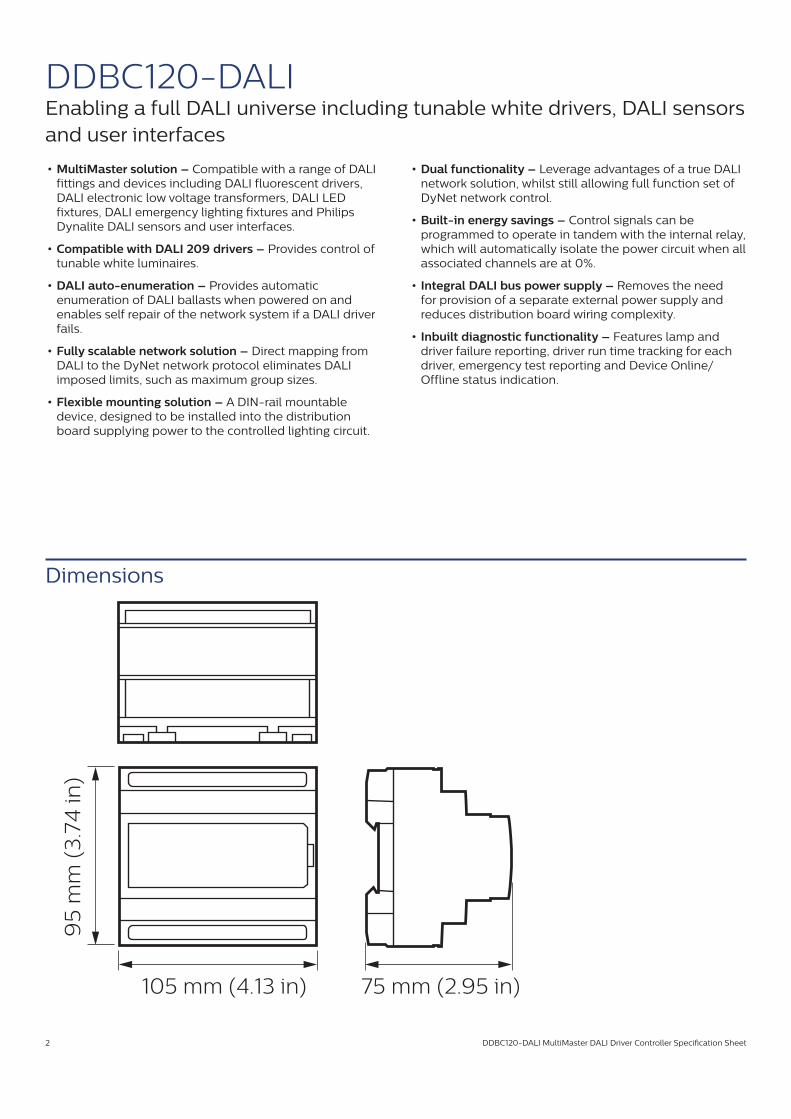
Dimensions
105 mm (4.13 in)
95
mm
(3
.74
in)
75 mm (2.95 in)
DDBC120-DALI MultiMaster DALI Driver Controller Specification Sheet 3
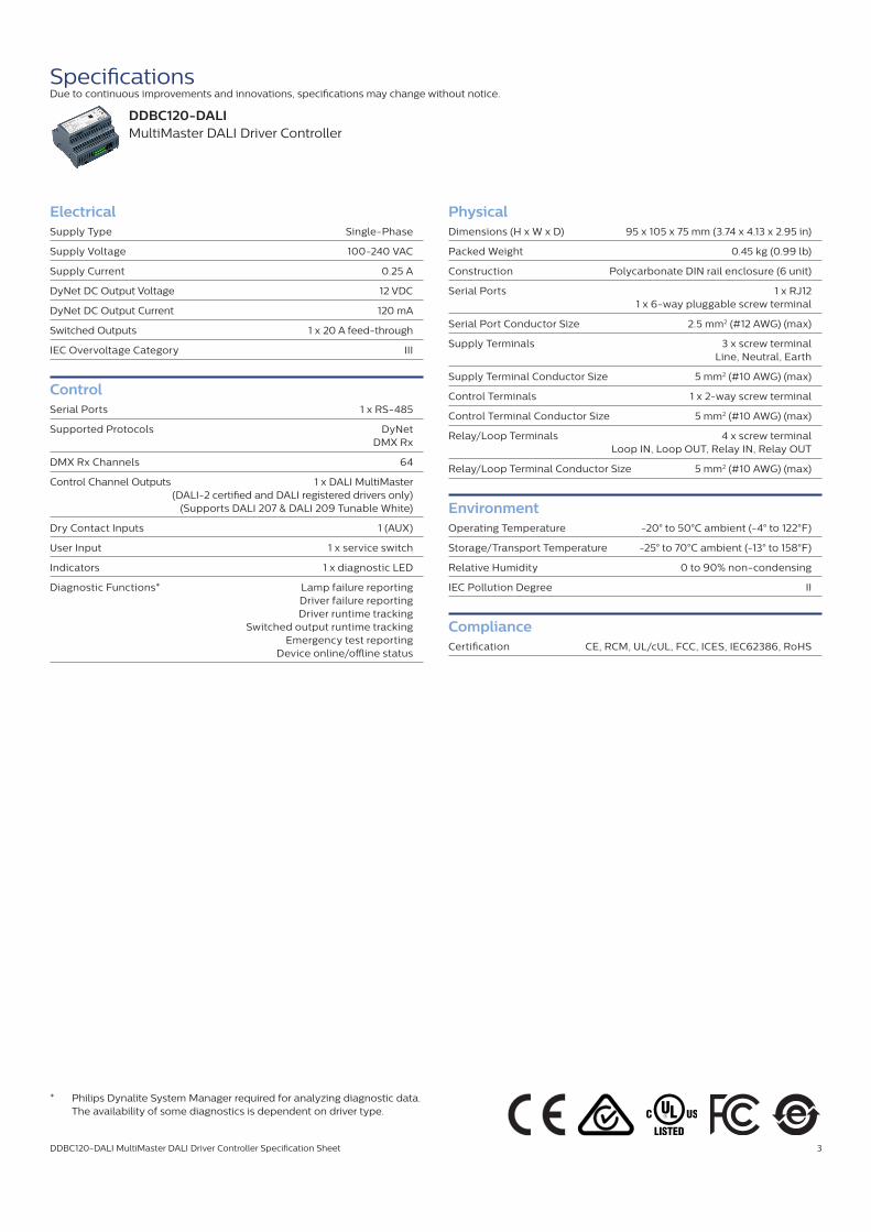
SpecificationsDue to continuous improvements and innovations, specifications may change without notice.
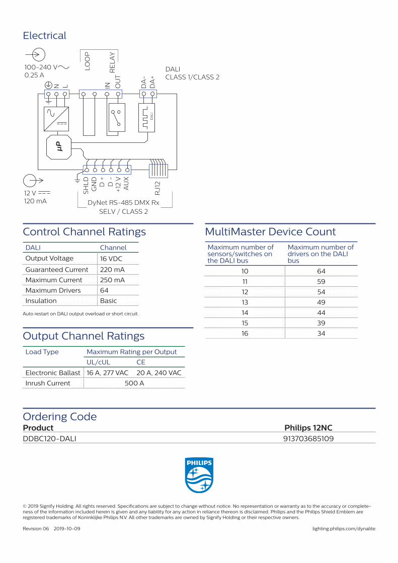
ElectricalSupply Type Single-Phase
Supply Voltage 100-240 VAC
Supply Current 0.25 A
DyNet DC Output Voltage 12 VDC
DyNet DC Output Current 120 mA
Switched Outputs 1 x 20 A feed-through
IEC Overvoltage Category III
ControlSerial Ports 1 x RS-485
Supported Protocols DyNet DMX Rx
DMX Rx Channels 64
Control Channel Outputs 1 x DALI MultiMaster (DALI-2 certified and DALI registered drivers only) (Supports DALI 207 & DALI 209 Tunable White)
Dry Contact Inputs 1 (AUX)
User Input 1 x service switch
Indicators 1 x diagnostic LED
Diagnostic Functions* Lamp failure reporting Driver failure reporting Driver runtime tracking Switched output runtime tracking Emergency test reporting Device online/offline status
PhysicalDimensions (H x W x D) 95 x 105 x 75 mm (3.74 x 4.13 x 2.95 in)
Packed Weight 0.45 kg (0.99 lb)
Construction Polycarbonate DIN rail enclosure (6 unit)
Serial Ports 1 x RJ12 1 x 6-way pluggable screw terminal
Serial Port Conductor Size 2.5 mm2 (#12 AWG) (max)
Supply Terminals 3 x screw terminal Line, Neutral, Earth
Supply Terminal Conductor Size 5 mm2 (#10 AWG) (max)
Control Terminals 1 x 2-way screw terminal
Control Terminal Conductor Size 5 mm2 (#10 AWG) (max)
Relay/Loop Terminals 4 x screw terminal Loop IN, Loop OUT, Relay IN, Relay OUT
Relay/Loop Terminal Conductor Size 5 mm2 (#10 AWG) (max)
EnvironmentOperating Temperature -20° to 50°C ambient (-4° to 122°F)
Storage/Transport Temperature -25° to 70°C ambient (-13° to 158°F)
Relative Humidity 0 to 90% non-condensing
IEC Pollution Degree II
ComplianceCertification CE, RCM, UL/cUL, FCC, ICES, IEC62386, RoHS
* Philips Dynalite System Manager required for analyzing diagnostic data. The availability of some diagnostics is dependent on driver type.
DDBC120-DALIMultiMaster DALI Driver Controller
Ordering Code
Electrical
Product Philips 12NCDDBC120-DALI 913703685109
µP
N L
LO
OP
RE
LA
Y
DA
-D
A+
IN OU
T
DALICLASS 1/CLASS 2
+12
V
D +
D -
GN
DS
HL
D
AU
X
RJ1
2
SELV / CLASS 2DyNet RS-485 DMX Rx
DA
LI
100-240 V0.25 A
12 V120 mA
Control Channel RatingsDALI Channel
Output Voltage 16 VDC
Guaranteed Current 220 mA
Maximum Current 250 mA
Maximum Drivers 64
Insulation Basic
Auto restart on DALI output overload or short circuit.
Output Channel RatingsLoad Type Maximum Rating per Output
UL/cUL CE
Electronic Ballast 16 A, 277 VAC 20 A, 240 VAC
Inrush Current 500 A
Maximum number of sensors/switches on the DALI bus
Maximum number of drivers on the DALI bus
10 64
11 59
12 54
13 49
14 44
15 39
16 34
MultiMaster Device Count
© 2019 Signify Holding. All rights reserved. Specifications are subject to change without notice. No representation or warranty as to the accuracy or complete-ness of the information included herein is given and any liability for any action in reliance thereon is disclaimed. Philips and the Philips Shield Emblem are registered trademarks of Koninklijke Philips N.V. All other trademarks are owned by Signify Holding or their respective owners.
Revision 06 2019-10-09 lighting.philips.com/dynalite