Dd13-Dd15 a&i Manual
304
7/14/2019 Dd13-Dd15 a&i Manual http://slidepdf.com/reader/full/dd13-dd15-ai-manual 1/304
Transcript of Dd13-Dd15 a&i Manual

7/14/2019 Dd13-Dd15 a&i Manual
http://slidepdf.com/reader/full/dd13-dd15-ai-manual 1/304

7/14/2019 Dd13-Dd15 a&i Manual
http://slidepdf.com/reader/full/dd13-dd15-ai-manual 2/304

7/14/2019 Dd13-Dd15 a&i Manual
http://slidepdf.com/reader/full/dd13-dd15-ai-manual 3/304
ATTENTION
This document is a guideline for qualified personnel. It is intended to be used by equipment
manufacturers and contains Detroit Diesel Corporation's recommendations for the ancillarysystems supporting the Detroit Diesel engines covered by this document. The equipment
manufacturer is responsible for developing, designing, manufacturing and installing these
systems, including component qualification. The equipment manufacturer is also responsible for
furnishing equipment users complete service and safety information for these systems. Detroit
Diesel Corporation makes no representations or warranties regarding the information contained in
installation of these ancillary systems, or the preparation or distribution to equipment users of
preliminary and incomplete and is subject to change without notice.
TRADEMARK INFORMATION
DD Platform, DDEC®, Ether Start®, Diagnostic Link® are registered trademarks of
Detroit Diesel Corporation. Fuel Pro® and Pro-Chek® are registered trademarks of DavcoManufacturing, L.L.C. Viton® is a registered trademark of DuPont Dow Elastomers L.L.C.
Loctite® is a registered trademark of Loctite Corporation. Delco Remy® is a registered trademark
of Delco Remy America, Inc. Leece-Neville® is a registered trademark of Leece-Neville
Company.

7/14/2019 Dd13-Dd15 a&i Manual
http://slidepdf.com/reader/full/dd13-dd15-ai-manual 4/304

7/14/2019 Dd13-Dd15 a&i Manual
http://slidepdf.com/reader/full/dd13-dd15-ai-manual 5/304
DD PLATFORM APPLICATION AND INSTALLATION MANUAL
DD PLATFORM APPLICATION AND INSTALLATIONMANUAL
ABSTRACT
This manual discusses the proper application and installation of the Detroit Diesel DD Platform
engine. The intention of this manual is to provide information in general terms so that it may be
applicable for all applications unless specifically noted or identified.
This manual contains the following information:
□ General information on safety precautions and on accessing installation drawings
□ Specific component and accessory information on various production models
□ Information on the air inlet, exhaust, cooling, f uel, lubrication, electrical, mounting, and
starting aid systems.
□ Information on the data can be found on the www.detroitdiesel.com, a website that provides
information such as technical data and installation drawings.
All information subject to change without notice. iDDC-SVC-MAN-0073 Copyright © 2009 DETROIT DIESEL CORPORATION

7/14/2019 Dd13-Dd15 a&i Manual
http://slidepdf.com/reader/full/dd13-dd15-ai-manual 6/304
ABSTRACT
ii All information subject to change without notice.
DDC-SVC-MAN-0073 Copyright © 2009 DETROIT DIESEL CORPORATION

7/14/2019 Dd13-Dd15 a&i Manual
http://slidepdf.com/reader/full/dd13-dd15-ai-manual 7/304
DD PLATFORM APPLICATION AND INSTALLATION MANUAL
TABLE OF CONTENTS
1 INTRODUCTION ................................................................................................................. 1- 1
2 SAFETY PRECAUTIONS ................................................................................................... 2- 1
2.1 SAFETY MEASURES ..................................................................................................... 2- 2
2.2 STANDS .......................................................................................................................... 2- 2
2.3 GLASSES ....................................................................................................................... 2- 2
2.4 WELDING ....................................................................................................................... 2- 2
2.5 WORK PLACE ............................................................................................................... 2- 4
2.6 CLOTHING ...................................................................................................................... 2- 5
2.7 ELECTRIC TOOLS ......................................................................................................... 2- 5
2.8 AIR .................................................................................................................................. 2- 5
2.9 FLUIDS AND PRESSURE .............................................................................................. 2- 5
2.10 BATTERIES .................................................................................................................... 2- 6
2.11 FIRE ................................................................................................................................ 2- 7
2.12 FLUOROELASTOMER ................................................................................................... 2- 7
3 ENGINE AND ACCESSORY IDENTIFICATION ................................................................. 3- 1
3.1 ENGINE AND ACCESSORY IDENTIFICATION DESCRIPTION ................................... 3- 2
3.2 MAJOR COMPONENT LOCATIONS .............................................................................. 3- 4
3.3 ENGINE IDENTIFICATION ............................................................................................. 3- 5
4 AIR INLET SYSTEM ........................................................................................................... 4- 1
4.1 AIR INLET SYSTEM DESCRIPTION .............................................................................. 4- 2
4.1.1 DD PLATFORM ON-HIGHWAY ENGINES ................................................................. 4- 2
4.2 INSTALLATION REQUIREMENTS ................................................................................. 4- 4
4.2.1 DRY PAPER ELEMENT AIR CLEANERS .................................................................. 4- 54.2.1.1 LIGHT-DUTY AIR CLEANER ............................................................................... 4- 5
4.2.1.2 MEDIUM-DUTY USE AIR CLEANER ................................................................... 4- 6
4.2.1.3 HEAVY-DUTY USE AIR CLEANER ..................................................................... 4- 7
4.2.1.4 EXTRA HEAVY-DUTY USE ................................................................................. 4- 9
4.2.1.5 FOAM TYPE AIR CLEANERS .............................................................................. 4-10
4.2.1.6 OIL-BATH AIR CLEANERS .................................................................................. 4-10
4.2.1.7 AUXILIARY PRECLEANERS ............................................................................... 4-10
4.2.1.8 INLET SCREENS ................................................................................................. 4-11
4.2.1.9 RAIN CAPS AND INLET HOODS ........................................................................ 4-11
4.2.1.10 WATER DRAINS ................................................................................................... 4-12
4.2.1.11 INLET SILENCERS .............................................................................................. 4-12
4.2.1.12 AIR CLEANER SELECTION ................................................................................ 4-12
4.2.2 RESTRICTION INDICATOR ....................................................................................... 4-13
4.2.3 PIPEWORK ................................................................................................................ 4-15
4.2.3.1 PIPEWORK MATERIAL SPECIFICATIONS ......................................................... 4-15
4.2.3.2 DIFFUSERS ......................................................................................................... 4-15
4.2.4 HOSE CONNECTIONS .............................................................................................. 4-16
4.3 DESIGN GUIDELINES .................................................................................................... 4-17
All information subject to change without notice. iiiDDC-SVC-MAN-0073 Copyright © 2009 DETROIT DIESEL CORPORATION

7/14/2019 Dd13-Dd15 a&i Manual
http://slidepdf.com/reader/full/dd13-dd15-ai-manual 8/304
TABLE OF CONTENTS
4.3.1 MAXIMUM AIR INLET FLOW .................................................................................... 4-17
4.3.2 AIR INLET SYSTEM RESTRICTION ......................................................................... 4-17
4.3.3 INLET LOCATION ...................................................................................................... 4-18
4.3.4 AIR-TO-AIR CHARGE AIR COOLER ........................................................................ 4-18
4.3.4.1 RESTRICTION AND TEMPERATURE REQUIREMENTS ................................... 4-20
4.3.4.2 CLEANLINESS ..................................................................................................... 4-20
4.3.4.3 LEAKAGE ............................................................................................................. 4-214.3.4.4 SIZE ...................................................................................................................... 4-21
4.3.4.5 COOLING AIR FLOW RESTRICTION ................................................................. 4-21
4.3.4.6 MATERIAL ............................................................................................................ 4-21
4.3.4.7 HEADER TANKS .................................................................................................. 4-22
4.3.4.8 LOCATION ............................................................................................................ 4-22
4.3.4.9 FAN SYSTEMS ..................................................................................................... 4-22
4.3.4.10 SHUTTERS .......................................................................................................... 4-22
4.3.4.11 WINTERFRONTS ................................................................................................. 4-23
4.4 TESTING REQUIREMENTS ........................................................................................... 4-23
4.4.1 TESTING LOCATION ................................................................................................. 4-23
4.4.2 INLET SYSTEM RESTRICTION ................................................................................ 4-244.4.3 AIR-TO-AIR SYSTEM EVALUATION TESTS ............................................................. 4-24
4.4.3.1 MAXIMUM TEMPERATURE RISE--AMBIENT TO INTAKE MANIFOLD ............. 4-24
4.4.3.2 CHARGE AIR COOLER SYSTEM RESTRICTION .............................................. 4-25
4.5 TEST ............................................................................................................................... 4-25
4.5.1 MOBILE AIR-TO-AIR .................................................................................................. 4-25
5 EXHAUST GAS RECIRCULATION SYSTEM ................................................................... 5- 1
5.1 EGR SYSTEM DESCRIPTION ....................................................................................... 5- 2
5.2 INSTALLATION AND DESIGN REQUIREMENTS .......................................................... 5- 3
5.2.1 COOLING SYSTEM ................................................................................................... 5- 3
5.2.2 AUXILIARY COOLERS .............................................................................................. 5- 35.3 TESTING REQUIREMENTS ........................................................................................... 5- 3
6 EXHAUST SYSTEM ........................................................................................................... 6- 1
6.1 EXHAUST SYSTEM DESCRIPTION .............................................................................. 6- 2
6.1.1 EXHAUST SYSTEM ................................................................................................... 6- 2
6.1.2 TURBOCHARGER ..................................................................................................... 6- 4
6.1.3 AXIAL POWER TURBINE .......................................................................................... 6- 4
6.2 INSTALLATION REQUIREMENTS ................................................................................. 6- 5
6.2.1 BACK PRESSURE ..................................................................................................... 6- 5
6.2.2 NOISE ......................................................................................................................... 6- 6
6.2.3 FLEXIBLE FITTINGS .................................................................................................. 6- 6
6.2.4 EXHAUST CONNECTION POINTS ........................................................................... 6- 6
6.2.5 MATERIAL SPECIFICATIONS FOR PIPEWORK ...................................................... 6- 8
6.3 DESIGN REQUIREMENTS ............................................................................................ 6- 8
6.3.1 TEMPERATURE DROP FROM TURBOCHARGER OUTLET TO
AFTERTREATMENT DEVICE .................................................................................... 6- 8
6.3.2 DISTANCE FROM HYDROCARBON DOSER TO ATD INLET .................................. 6- 8
6.3.3 OUTLET LOCATION .................................................................................................. 6- 8
6.3.4 DRAINAGE ................................................................................................................. 6- 9
iv All information subject to change without notice.
DDC-SVC-MAN-0073 Copyright © 2009 DETROIT DIESEL CORPORATION

7/14/2019 Dd13-Dd15 a&i Manual
http://slidepdf.com/reader/full/dd13-dd15-ai-manual 9/304
DD PLATFORM APPLICATION AND INSTALLATION MANUAL
6.3.5 SYSTEM INSULATION ............................................................................................... 6- 9
6.3.6 BENDING MOMENT CALCULATIONS ...................................................................... 6- 9
6.4 TESTING REQUIREMENTS ........................................................................................... 6- 9
6.4.1 MEASUREMENT OF EXHAUST BACK PRESSURE ................................................ 6-10
6.4.2 MEASUREMENT OF TEMPERATURE DROP FROM TURBOCHARGER TO ATD
INLET .......................................................................................................................... 6-11
6.4.3 MEASUREMENT OF EXHAUST LEAKAGE BETWEEN TURBOCHARGER AND ATD INLET .................................................................................................................. 6-12
7 AFTERTREATMENT SYSTEM ........................................................................................... 7- 1
7.1 AFTERTREATMENT SYSTEM DESCRIPTION ............................................................. 7- 2
7.2 SYSTEM DESCRIPTION / OPERATION ........................................................................ 7- 4
7.2.1 AFTERTREATMENT DEVICE ................................................................................... 7- 6
7.2.2 INTAKE THROTTLE ................................................................................................... 7- 7
7.2.3 HYDROCARBON (HC) DOSER ................................................................................. 7- 8
7.3 AFTERTREATMENT DEVICE DESIGN FEATURES ...................................................... 7-10
7.3.1 FEET / HOOKS ........................................................................................................... 7-10
7.3.2 LOCATING DEVICE ................................................................................................... 7-10
7.3.3 SENSOR BOX DISCUSSION ..................................................................................... 7-11
7.3.4 V-BAND CLAMPS ...................................................................................................... 7-11
7.3.5 SENSOR AND HARNESS .......................................................................................... 7-11
7.4 AFTERTREATMENT DEVICE VARIATIONS .................................................................. 7-11
7.5 NOISE ATTENUATION ................................................................................................... 7-12
7.6 MASS OF THE AFTERTREATMENT DEVICE ............................................................... 7-12
7.7 MOUNTING REQUIREMENTS ....................................................................................... 7-12
7.7.1 MOUNTING ZONES ................................................................................................... 7-13
7.7.2 BENDING MOMENT FOR INLETS AND OUTLETS .................................................. 7-13
7.7.3 DRAINAGE ................................................................................................................. 7-13
8 COOLING SYSTEM, AIR-TO-AIR CHARGE COOLING .................................................... 8- 1
8.1 COOLING SYSTEM, AIR-TO-AIR CHARGE COOLING SYSTEM DESCRIPTION ....... 8- 2
8.2 JACKET WATER COOLING SYSTEM ........................................................................... 8- 2
8.3 THERMOSTAT ................................................................................................................ 8- 4
8.3.1 VENTING ................................................................................................................... 8- 6
8.4 WATER PUMP ............................................................................................................... 8- 7
8.5 TYPES OF COOLING SYSTEMS ................................................................................... 8- 8
8.5.1 RAPID WARM-UP COOLING SYSTEM RECOMMENDED DESIGN ........................ 8- 8
8.5.2 AUXILIARY AIR-COOLED COOLER CORES ............................................................ 8-10
8.5.3 COOLANT HEATERS ................................................................................................. 8-10
8.6 AIR-TO-AIR CHARGE COOLING ................................................................................... 8-10
8.6.1 CHARGE AIR COOLER ............................................................................................. 8-12
8.7 COOLING SYSTEM PERFORMANCE REQUIREMENTS ............................................. 8-13
8.7.1 SYSTEM FILL ............................................................................................................. 8-13
8.7.2 SYSTEM DRAIN ......................................................................................................... 8-13
8.7.3 DEAERATION ............................................................................................................. 8-13
8.7.4 SYSTEM COOLANT CAPACITY ................................................................................ 8-14
8.7.5 DRAWDOWN CAPACITY ........................................................................................... 8-16
8.7.6 CORE CONSTRUCTION ........................................................................................... 8-16
All information subject to change without notice. vDDC-SVC-MAN-0073 Copyright © 2009 DETROIT DIESEL CORPORATION
7/14/2019 Dd13-Dd15 a&i Manual
http://slidepdf.com/reader/full/dd13-dd15-ai-manual 10/304
TABLE OF CONTENTS
8.7.7 WATER PUMP INLET PRESSURE/MAXIMUM STATIC HEAD ................................. 8-16
8.7.8 COOLANT FLOW RATE/EXTERNAL PRESSURE DROP ........................................ 8-16
8.7.9 MINIMUM COOLANT TEMPERATURE ..................................................................... 8-17
8.7.10 SYSTEM PRESSURIZATION ..................................................................................... 8-17
8.7.11 COOLANTS ................................................................................................................ 8-17
8.8 CHARGE AIR COOLING REQUIREMENTS .................................................................. 8-17
8.8.1 COOLING CAPABILITY .............................................................................................. 8-178.8.2 MAXIMUM PRESSURE LOSS ................................................................................... 8-17
8.8.3 CLEANLINESS ........................................................................................................... 8-18
8.8.4 LEAKAGE ................................................................................................................... 8-18
8.9 VEHICLE SIGN-OFF ....................................................................................................... 8-18
8.10 COOLING SYSTEM DESIGN CONSIDERATIONS ........................................................ 8-18
8.10.1 COOLING SYSTEM REQUIREMENTS ..................................................................... 8-18
8.10.1.1 ENGINE OPERATING TEMPERATURE .............................................................. 8-18
8.10.1.2 INTAKE MANIFOLD TEMPERATURE ................................................................. 8-19
8.10.2 ENGINE PERFORMANCE ......................................................................................... 8-19
8.10.2.1 ENGINE HEAT REJECTION ................................................................................ 8-19
8.10.2.2 COOLANT FLOW ................................................................................................. 8-198.10.2.3 HEAT TRANSFER CAPABILITIES ....................................................................... 8-19
8.10.3 ENVIRONMENTAL AND OPERATING CONDITIONS ............................................... 8-20
8.10.3.1 AMBIENT TEMPERATURE .................................................................................. 8-20
8.10.3.2 ALTITUDE ............................................................................................................. 8-21
8.10.3.3 SPACE CONSTRAINTS ....................................................................................... 8-21
8.10.3.4 NOISE LIMITS ...................................................................................................... 8-21
8.10.3.5 TILT OPERATIONS OR INSTALLATIONS ........................................................... 8-21
8.10.4 SYSTEM COMPONENTS .......................................................................................... 8-21
8.10.4.1 ADDITIONAL HEAT LOADS TO COOLANT ........................................................ 8-21
8.10.4.2 ADDITIONAL HEAT LOADS TO AIR .................................................................... 8-22
8.10.4.3 COOLANT TYPE .................................................................................................. 8-228.10.4.4 PLUMBING .......................................................................................................... 8-22
8.10.4.5 AUXILIARY COOLANT FLOW PATH CIRCUITRY ............................................... 8-24
8.10.4.6 WATER COOLED EXHAUST SYSTEMS ............................................................. 8-24
8.10.4.7 WATER PUMPS ................................................................................................... 8-24
8.11 CHARGE AIR COOLING DESIGN GUIDELINES ........................................................... 8-25
8.11.1 SIZE ............................................................................................................................ 8-25
8.11.2 COOLING AIR FLOW RESTRICTION ....................................................................... 8-26
8.11.3 MATERIAL .................................................................................................................. 8-26
8.11.4 HEADER TANKS ........................................................................................................ 8-26
8.11.5 LOCATION .................................................................................................................. 8-26
8.11.6 PIPEWORK ................................................................................................................ 8-26
8.12 HEAT EXCHANGER SELECTION .................................................................................. 8-27
8.12.1 SHELL AND TUBE HEAT EXCHANGERS ................................................................. 8-27
8.13 FAN SYSTEM RECOMMENDATIONS AND FAN SELECTION ..................................... 8-28
8.13.1 BLOWER VS. SUCTION FANS .................................................................................. 8-29
8.13.1.1 FAN PERFORMANCE .......................................................................................... 8-30
8.13.1.2 FAN POSITION ..................................................................................................... 8-33
8.13.1.3 FAN SHROUDS .................................................................................................... 8-34
vi All information subject to change without notice.
DDC-SVC-MAN-0073 Copyright © 2009 DETROIT DIESEL CORPORATION

7/14/2019 Dd13-Dd15 a&i Manual
http://slidepdf.com/reader/full/dd13-dd15-ai-manual 11/304
DD PLATFORM APPLICATION AND INSTALLATION MANUAL
8.13.1.4 FAN SYSTEM ASSEMBLIES ............................................................................... 8-35
8.13.1.5 FAN DRIVES ........................................................................................................ 8-35
8.13.1.6 BAFFLES TO PREVENT AIR RECIRCULATION ................................................. 8-35
8.13.1.7 SHUTTERS .......................................................................................................... 8-35
8.13.1.8 WINTERFRONTS ................................................................................................. 8-35
8.14 RADIATOR COMPONENT DESIGN ............................................................................... 8-36
8.14.1 DOWN FLOW AND CROSS FLOW RADIATORS ...................................................... 8-368.14.1.1 HORIZONTAL RADIATOR .................................................................................... 8-36
8.14.1.2 RAPID WARM-UP DEAERATION TANK — DOWN FLOW RADIATOR .............. 8-36
8.14.1.3 REMOTE MOUNTED RADIATORS/HEAT EXCHANGER ................................... 8-37
8.14.1.4 INTEGRAL TOP TANK ......................................................................................... 8-37
8.14.1.5 REMOTE TANK .................................................................................................... 8-40
8.14.1.6 RADIATOR BOTTOM TANK ................................................................................. 8-42
8.14.1.7 COOLANT PRESSURE CONTROL CAPS AND RELIEF VALVES ...................... 8-44
8.14.1.8 THERMOSTAT ..................................................................................................... 8-46
8.14.1.9 COOLANT SENSOR DEVICES ........................................................................... 8-47
8.14.1.10 COOLANT RECOVERY SYSTEM ....................................................................... 8-48
8.14.2 COLD WEATHER OPERATING OPTIMIZATION ....................................................... 8-548.14.2.1 ENGINE ................................................................................................................ 8-54
8.14.2.2 VEHICLE .............................................................................................................. 8-54
8.14.2.3 COOLING SYSTEM ............................................................................................. 8-54
8.14.2.4 HEATER CIRCUIT ................................................................................................ 8-54
8.14.3 COOLANT HEATERS ................................................................................................. 8-55
8.14.4 MULTI-DUTY CYCLE ................................................................................................. 8-55
8.14.5 OTHER CONSIDERATIONS ...................................................................................... 8-55
8.15 COOLING SYSTEM EVALUATION TESTS .................................................................... 8-55
8.15.1 SYSTEM DESCRIPTION ........................................................................................... 8-56
8.15.2 INSTRUMENTATION .................................................................................................. 8-56
8.15.2.1 THERMOCOUPLES AND ASSOCIATED HARDWARE ....................................... 8-568.15.2.2 PRESSURE GAUGES AND ASSOCIATED HARDWARE ................................... 8-57
8.15.2.3 THERMOSTAT ..................................................................................................... 8-57
8.15.2.4 SIGHT GLASS AND TRANSPARENT TUBING ................................................... 8-58
8.15.2.5 GRADUATED CONTAINER ................................................................................. 8-59
8.15.2.6 PRESSURE CAP .................................................................................................. 8-59
8.15.2.7 STOP WATCH ...................................................................................................... 8-59
8.15.2.8 LIGHT .................................................................................................................. 8-59
8.15.2.9 WATER SUPPLY AND HOSE ............................................................................. 8-59
8.15.2.10 ENGINE LOADING METHOD .............................................................................. 8-59
8.15.2.11 TAPE MEASURE .................................................................................................. 8-59
8.15.2.12 FLOWMETERS AND ASSOCIATED HARDWARE .............................................. 8-60
8.15.3 TEST PREPARATIONS .............................................................................................. 8-60
8.15.4 TYPES OF TESTS ..................................................................................................... 8-61
8.15.4.1 CONTINUOUS FILL ............................................................................................. 8-61
8.15.4.2 INTERRUPTED FILL ............................................................................................ 8-62
8.15.4.3 BUCKET FILL ....................................................................................................... 8-62
8.15.4.4 TOTAL SYSTEM CAPACITY ................................................................................ 8-63
8.15.4.5 DRAINING CAPABILITY ....................................................................................... 8-63
All information subject to change without notice. viiDDC-SVC-MAN-0073 Copyright © 2009 DETROIT DIESEL CORPORATION

7/14/2019 Dd13-Dd15 a&i Manual
http://slidepdf.com/reader/full/dd13-dd15-ai-manual 12/304
TABLE OF CONTENTS
8.15.4.6 WATER PUMP BINDING TEST ............................................................................ 8-63
8.15.4.7 DEAERATION TEST ............................................................................................ 8-63
8.15.4.8 DRAWDOWN TEST ............................................................................................. 8-64
8.15.4.9 WATER FLOW AND PRESSURE TEST .............................................................. 8-66
8.15.4.10 COOLING INDEX TEST ....................................................................................... 8-66
8.15.5 CHARGE AIR COOLING EVALUATION TEST .......................................................... 8-70
8.15.6 SYSTEM DESCRIPTION ........................................................................................... 8-718.15.7 INSTRUMENTATION .................................................................................................. 8-72
8.15.7.1 TEMPERATURE MEASUREMENT ...................................................................... 8-72
8.15.7.2 PRESSURE MEASUREMENT ............................................................................. 8-72
8.15.8 LOCATION .................................................................................................................. 8-74
8.15.9 INLET SYSTEM RESTRICTION ................................................................................ 8-75
8.15.9.1 MAXIMUM TEMPERATURE RISE — AMBIENT TO TURBOCHARGER INLET . 8-75
8.15.9.2 AIR-TO-AIR SYSTEM EVALUATION TESTS ....................................................... 8-75
8.15.9.3 MAXIMUM TEMPERATURE RISE — AMBIENT TO INTAKE MANIFOLD .......... 8-75
8.15.9.4 CHARGE AIR COOLER SYSTEM RESTRICTION .............................................. 8-75
8.15.10 TEST ........................................................................................................................... 8-76
8.15.11 TEST ANALYSIS ........................................................................................................ 8-768.16 COOLING SYSTEM DIAGNOSTICS AND TROUBLESHOOTING GUIDE .................... 8-76
8.16.1 ENGINE OVERHEAT ................................................................................................. 8-77
8.16.1.1 TROUBLESHOOTING FOR ENGINE OVERHEAT .............................................. 8-77
8.16.2 COLD RUNNING ENGINE (OVERCOOLING) ........................................................... 8-79
8.16.3 POOR CAB HEATER PERFORMANCE .................................................................... 8-79
8.16.3.1 THERMOSTAT LEAKAGE TEST ......................................................................... 8-80
8.16.3.2 CAC AIR LEAKAGE TEST ................................................................................... 8-82
8.17 MAINTENANCE .............................................................................................................. 8-83
9 FUEL SYSTEM ................................................................................................................... 9- 1
9.1 FUEL SYSTEM DESCRIPTION ...................................................................................... 9- 29.2 FUEL SYSTEM EQUIPMENT/INSTALLATION GUIDELINES ........................................ 9- 5
9.2.1 FUEL TANK ................................................................................................................ 9- 5
9.2.1.1 MATERIAL ............................................................................................................ 9- 5
9.2.1.2 DESIGN ................................................................................................................ 9- 5
9.2.1.3 CAPACITY ............................................................................................................ 9- 6
9.2.1.4 POSITION ............................................................................................................. 9- 6
9.2.2 FUEL FILTERS/FUEL FILTER MODULE ................................................................... 9- 7
9.2.3 FUEL FILTER CONFIGURATION ............................................................................... 9- 7
9.2.4 FUEL LINES ............................................................................................................... 9- 7
9.2.4.1 DESIGN ................................................................................................................ 9- 8
9.2.4.2 MATERIAL ............................................................................................................ 9- 89.2.4.3 SIZE ...................................................................................................................... 9- 8
9.3 FUEL SELECTION .......................................................................................................... 9- 9
10 LUBRICATION SYSTEM .................................................................................................... 10- 1
10.1 LUBRICATION SYSTEM DESCRIPTION ...................................................................... 10- 2
10.2 LUBRICATION OIL SELECTION .................................................................................... 10- 4
10.3 LUBRICATION FILTER ................................................................................................... 10- 4
10.3.1 SUPPLEMENTAL FILTRATION SYSTEMS ................................................................ 10- 4
viii All information subject to change without notice.
DDC-SVC-MAN-0073 Copyright © 2009 DETROIT DIESEL CORPORATION

7/14/2019 Dd13-Dd15 a&i Manual
http://slidepdf.com/reader/full/dd13-dd15-ai-manual 13/304
DD PLATFORM APPLICATION AND INSTALLATION MANUAL
10.4 ENGINE COMPONENT OIL SUPPLY REQUIREMENTS .............................................. 10- 4
10.4.1 TURBOCHARGER LUBRICATION ............................................................................ 10- 5
10.4.2 AIR COMPRESSOR LUBRICATION .......................................................................... 10- 5
10.4.3 CRANKCASE BREATHER LUBRICATION ................................................................ 10- 5
10.5 COMPONENT OPTIONS & INSTALLATION REQUIREMENTS .................................... 10- 5
10.5.1 OIL SAMPLING VALVE ............................................................................................. 10- 5
10.5.2 OIL CHECKS AND FILLS ........................................................................................... 10- 510.5.3 OIL SUMPS ................................................................................................................ 10- 6
10.5.4 ENVIRONMENTALLY SAFE OIL CHANGE (ESOC) FITTINGS ................................ 10- 6
10.5.5 OIL IMMERSION HEATERS ...................................................................................... 10- 6
10.5.6 OIL LEVEL SENSORS ............................................................................................... 10- 6
10.6 OPERATION AND MAINTENANCE ............................................................................... 10- 7
10.6.1 FIRST TIME START ................................................................................................... 10- 7
10.6.2 OIL LEVEL MEASUREMENTS .................................................................................. 10- 7
10.6.3 USED OIL ANALYSIS ................................................................................................. 10- 7
10.6.4 OIL DRAIN INTERVALS ............................................................................................. 10- 7
11 ELECTRICAL SYSTEM ...................................................................................................... 11- 1
11.1 ELECTRICAL SYSTEM DESCRIPTION ......................................................................... 11- 2
11.2 INSTALLATION GUIDELINES ........................................................................................ 11- 3
11.2.1 BATTERY ................................................................................................................... 11- 3
11.2.1.1 FILLER CAP BATTERIES .................................................................................... 11- 3
11.2.1.2 SEMI-MAINTENANCE FREE BATTERIES .......................................................... 11- 3
11.2.1.3 MAINTENANCE-FREE BATTERIES .................................................................... 11- 3
11.2.1.4 DEEP CYCLE BATTERIES .................................................................................. 11- 4
11.2.1.5 GEL-CELL AND NICKEL CADMIUM BATTERIES ............................................... 11- 4
11.2.1.6 BATTERY CAPACITY ........................................................................................... 11- 4
11.2.1.7 BATTERY MOUNTING AND LOCATION ............................................................. 11- 4
11.2.2 CRANKING MOTOR .................................................................................................. 11- 511.2.3 ALTERNATORS .......................................................................................................... 11- 9
11.2.3.1 ALTERNATOR MOUNTING .................................................................................. 11-10
11.2.4 GROUNDING REQUIREMENTS ............................................................................... 11-11
11.2.5 WIRING ...................................................................................................................... 11-11
11.2.5.1 GUIDELINES FOR ELECTRICAL WIRING .......................................................... 11-11
11.2.5.2 CABLE LOSS TEST PROCEDURE ..................................................................... 11-12
11.2.5.3 MEASURING CIRCUIT RESISTANCE ................................................................. 11-12
11.2.5.4 CALCULATING CIRCUIT RESISTANCE ............................................................. 11-13
12 MOUNTING SYSTEM ......................................................................................................... 12- 1
12.1 MOUNTING SYSTEM DESCRIPTION ........................................................................... 12- 2
12.1.1 THREE-POINT MOUNTING ....................................................................................... 12- 2
12.2 SOLID MOUNTING SYSTEMS ....................................................................................... 12- 3
12.3 FLEXIBLE MOUNTING SYSTEMS ................................................................................. 12- 4
12.3.1 FLEXIBLE MOUNT SELECTION ............................................................................... 12- 4
12.3.1.1 METHOD A ........................................................................................................... 12- 5
12.3.1.2 METHOD B ........................................................................................................... 12- 6
12.4 INSTALLATION CHECK LIST ......................................................................................... 12- 6
12.5 ENGINE SUPPORT ........................................................................................................ 12- 7
All information subject to change without notice. ixDDC-SVC-MAN-0073 Copyright © 2009 DETROIT DIESEL CORPORATION

7/14/2019 Dd13-Dd15 a&i Manual
http://slidepdf.com/reader/full/dd13-dd15-ai-manual 14/304
TABLE OF CONTENTS
13 TORSIONAL ANALYSIS .................................................................................................... 13- 1
13.1 TORSIONAL ANALYSIS DESCRIPTION ........................................................................ 13- 2
13.2 MASS ELASTIC DATA .................................................................................................... 13- 2
13.3 TORSIONAL ANALYSIS REQUEST FORM ................................................................... 13- 6
14 ENGINE ELECTRONIC CONTROLS ................................................................................ 14- 1
14.1 ENGINE ELECTRONIC CONTROLS DESCRIPTION .................................................... 14- 2
14.2 ORIGINAL EQUIPMENT MANUFACTURER INSTALLATION REQUIREMENTS .......... 14- 2
14.3 MOTOR CONTROL MODULE ........................................................................................ 14- 3
14.4 COMMON POWERTRAIN CONTROLLER .................................................................... 14- 3
14.5 ELECTRONIC FUEL INJECTOR .................................................................................... 14- 4
14.6 WIRING HARNESSES .................................................................................................... 14- 5
14.6.1 INJECTOR HARNESSES ........................................................................................... 14- 6
14.6.2 VEHICLE INTERFACE HARNESS ............................................................................. 14- 6
14.6.3 COMMUNICATION BETWEEN ELECTRONIC SYSTEMS ........................................ 14- 8
14.6.4 ENGINE SENSOR HARNESS ................................................................................... 14- 8
14.6.5 DIESEL PARTICULATE FILTER HARNESS .............................................................. 14- 8
14.7 SYSTEM SENSORS ....................................................................................................... 14- 814.8 WELDING ....................................................................................................................... 14-11
15 AUXILIARY AIR SYSTEMS ................................................................................................ 15- 1
15.1 AIR START ...................................................................................................................... 15- 2
15.1.1 SYSTEM RECOMMENDATIONS ............................................................................... 15- 2
15.1.1.1 AIR TANKS ........................................................................................................... 15- 2
15.1.1.2 AIR CONTROL SYSTEM ..................................................................................... 15- 2
15.1.1.3 AIR STARTERS REQUIRING LUBRICATORS .................................................... 15- 3
15.2 AIR COMPRESSOR ....................................................................................................... 15- 3
15.2.1 16 CFM AND 32 CFM COMPRESSORS ................................................................... 15- 4
16 COLD WEATHER STARTING AND STARTING AID SYSTEMS ....................................... 16- 1
16.1 COLD WEATHER STARTING AND STARTING AID SYSTEMS DESCRIPTION .......... 16- 2
16.2 PREPARATION ............................................................................................................... 16- 3
16.2.1 LUBRICATING OIL ..................................................................................................... 16- 3
16.2.2 DIESEL FUEL ............................................................................................................. 16- 4
16.2.3 COOLANT .................................................................................................................. 16- 4
16.2.4 BATTERY ................................................................................................................... 16- 6
16.2.5 STARTER MOTOR ..................................................................................................... 16- 7
16.2.5.1 ELECTRIC STARTER MOTOR ............................................................................ 16- 7
16.3 COLD WEATHER STARTING ......................................................................................... 16- 8
16.3.1 STARTING SYSTEMS ................................................................................................ 16- 8
16.3.1.1 INTAKE AIR HEATER ........................................................................................... 16- 8
16.3.1.2 COOLANT TANK TYPE HEATERS ...................................................................... 16- 8
16.3.1.3 ENGINE BLOCK HEATER ................................................................................... 16-11
16.3.1.4 OIL PAN HE ATER ................................................................................................ 16-11
16.3.1.5 FUEL ..................................................................................................................... 16-11
16.3.1.6 FUEL HEATERS ................................................................................................... 16-11
16.3.1.7 BATTERY HEATER TYPES ................................................................................. 16-11
16.3.1.8 HEATING ENGINE COMPARTMENT .................................................................. 16-12
x All information subject to change without notice.
DDC-SVC-MAN-0073 Copyright © 2009 DETROIT DIESEL CORPORATION

7/14/2019 Dd13-Dd15 a&i Manual
http://slidepdf.com/reader/full/dd13-dd15-ai-manual 15/304
DD PLATFORM APPLICATION AND INSTALLATION MANUAL
16.3.2 STARTING PROCEDURES ........................................................................................ 16-12
16.3.3 ENGINE STARTING REQUIREMENTS .................................................................... 16-13
16.4 COLD WEATHER OPERATION ...................................................................................... 16-13
16.4.1 ETHER INJECTION .................................................................................................... 16-13
16.4.2 IDLING AND LIGHT LOAD ......................................................................................... 16-13
16.4.3 MAINTENANCE .......................................................................................................... 16-13
16.4.4 WIND PROTECTION .................................................................................................. 16-1416.4.5 BATTERY AND CHARGING SYSTEM ....................................................................... 16-14
16.4.6 AIR CLEANER MAINTENANCE ................................................................................. 16-14
16.4.7 SUPPLEMENTAL HEATING DEVICE ........................................................................ 16-14
16.4.8 DDC COLD START RECOMMENDATIONS .............................................................. 16-14
17 ACCESSORY DRIVE SYSTEM .......................................................................................... 17- 1
17.1 ACCESSORY DRIVES ................................................................................................... 17- 2
17.2 GEARTRAIN ................................................................................................................... 17- 2
17.2.1 GEARTRAIN GEAR DRIVE RATIOS .......................................................................... 17- 3
17.3 DRIVETRAIN .................................................................................................................. 17- 4
17.4 BENDING MOMENT ....................................................................................................... 17- 5
18 AUXILIARY POWER UNITS (APU) .................................................................................... 18- 1
18.1 AUXILIARY POWER UNITS (APU) ................................................................................ 18- 2
18.2 APU DESCRIPTION ....................................................................................................... 18- 2
18.3 INSTALLATION REQUIREMENTS ................................................................................. 18- 3
18.3.1 APU FUEL SYSTEM .................................................................................................. 18- 4
18.3.2 APU COOLANT SYSTEM .......................................................................................... 18- 6
18.3.3 APU EXHAUST SYSTEM ........................................................................................... 18- 9
18.3.4 APU ELECTRICAL SYSTEM ..................................................................................... 18- 9
18.4 APU ENGINE START-UP PROCEDURE ....................................................................... 18-11
18.4.1 BLEEDING THE COOLANT SYSTEM ....................................................................... 18-11
18.4.2 BLEEDING THE FUEL LINES .................................................................................... 18-12
18.4.3 VERIFYING ENGINE OPERATION ............................................................................ 18-12
18.5 EXAMPLE INSTALLATION PHOTOS ............................................................................. 18-13
19 EFFECTS OF ENVIRONMENTAL CONDITIONS .............................................................. 19- 1
19.1 EFFECTS OF ENVIRONMENTAL CONDITIONS DESCRIPTION ................................. 19- 2
19.2 AIR INLET TEMPERATURE ........................................................................................... 19- 2
19.3 EXHAUST BACK PRESSURE ........................................................................................ 19- 2
19.4 FUEL TEMPERATURE ................................................................................................... 19- 3
19.5 ALTITUDE ....................................................................................................................... 19- 3
APPENDIX A: ABBREVIATIONS / ACRONYMS ......................................................................... A- 1
APPENDIX B: VENDORS ............................................................................................................. B- 1
GLOSSARY ..................................................................................................................................... G- 1
All information subject to change without notice. xiDDC-SVC-MAN-0073 Copyright © 2009 DETROIT DIESEL CORPORATION

7/14/2019 Dd13-Dd15 a&i Manual
http://slidepdf.com/reader/full/dd13-dd15-ai-manual 16/304
TABLE OF CONTENTS
xii All information subject to change without notice.
DDC-SVC-MAN-0073 Copyright © 2009 DETROIT DIESEL CORPORATION
7/14/2019 Dd13-Dd15 a&i Manual
http://slidepdf.com/reader/full/dd13-dd15-ai-manual 17/304
DD PLATFORM APPLICATION AND INSTALLATION MANUAL
LIST OF FIGURES
Figure 3-1 DD Platform On-Highway Engine ...................................................................... 3- 2
Figure 3-2 Exhaust and Intake Valves ................................................................................ 3- 3
Figure 3-3 Cylinder Designation and Firing Order, DD Platform ........................................ 3- 3Figure 3-4 Right Side Engine View ..................................................................................... 3- 4
Figure 3-5 Left Side Engine View ....................................................................................... 3- 5
Figure 3-6 The Engine Serial Numbers Stamp and Model Number, DD Platform .............. 3- 6
Figure 3-7 Rocker Cover with Option Label ....................................................................... 3- 6
Figure 4-1 Air Intake System Schematic – On-Highway .................................................... 4- 3
Figure 4-2 Intake Manifold and Related Parts .................................................................... 4- 4
Figure 4-3 Light-Duty Air Cleaner, Single Stage Cartridge Type ........................................ 4- 6
Figure 4-4 Medium-Duty Air Cleaner .................................................................................. 4- 7
Figure 4-5 Heavy-Duty Air Cleaner .................................................................................... 4- 8
Figure 4-6 Extra Heavy-Duty Air Cleaner ........................................................................... 4- 9
Figure 4-7 Precleaner Centrifugal Action ........................................................................... 4-11Figure 4-8 Rain Cap and Inlet Hood ................................................................................... 4-12
Figure 4-9 Altitude vs. Inlet Restriction .............................................................................. 4-14
Figure 4-10 Acceptable Diffuser Configurations ................................................................... 4-16
Figure 4-11 Air Inlet System Calculation .............................................................................. 4-18
Figure 4-12 Typical Radiator-mounted Charge Air Cooling System Right Side View .......... 4-19
Figure 4-13 Typical Radiator-Mounted Charge Air Cooling System Left Side View ............. 4-19
Figure 4-14 Typical Instrumentation Location ....................................................................... 4-24
Figure 4-15 Air Inlet Data Sheet for Turbocharged and Air-to-Air Charge Cooled Engine ... 4-26
Figure 4-16 Air Inlet System Data Sheet for Turbocharged Engines ................................... 4-27
Figure 5-1 EGR System ..................................................................................................... 5- 2
Figure 6-1 Turbocharger and Related Parts ....................................................................... 6- 3Figure 6-2 Turbine Outlet Connection Points for DD15™ .................................................. 6- 7
Figure 6-3 Turbine Outlet Connection Points for DD13™ .................................................. 6- 7
Figure 6-4 Piezometer Ring ................................................................................................ 6-10
Figure 6-5 Static Pressure Tap ........................................................................................... 6-11
Figure 7-1 Components of Af tertreatment System ............................................................. 7- 3
Figure 7-2 DD Platform Aftertreatment System Schematic ................................................ 7- 4
Figure 7-3 Aftertreatment System Components ................................................................. 7- 5
Figure 7-4 Aftertreatment Device Components .................................................................. 7- 6
Figure 7-5 Operation of the Diesel Particulate Filter .......................................................... 7- 7
Figure 7-6 Location of the Intake Throttle ........................................................................... 7- 8
Figure 7-7 Hydrocarbon (HC) Doser Location .................................................................... 7- 9Figure 7-8 Hydrocarbon (HC) Doser Location .................................................................... 7- 9
Figure 7-9 Typical Mounting Views of an Aftertreatment Device ........................................ 7-10
Figure 7-10 Aftertreatment Device Orientation Variations .................................................... 7-12
Figure 8-1 Engine Jacket Water Cooling System — Thermostats Closed ......................... 8- 3
Figure 8-2 Engine Jacket Water Cooling System — Thermostats Fully Open ................... 8- 3
Figure 8-3 Ther mostat and Related Parts .......................................................................... 8- 4
Figure 8-4 Cooling System Operation ................................................................................ 8- 5
All information subject to change without notice. xiiiDDC-SVC-MAN-0073 Copyright © 2009 DETROIT DIESEL CORPORATION

7/14/2019 Dd13-Dd15 a&i Manual
http://slidepdf.com/reader/full/dd13-dd15-ai-manual 18/304
TABLE OF CONTENTS
Figure 8-5 Cooling System Operation ................................................................................ 8- 6
Figure 8-6 Vent Location .................................................................................................... 8- 7
Figure 8-7 Water Pump Mounting ...................................................................................... 8- 8
Figure 8-8 Rapid Warm-up Cooling System — Remote Tank, Cross Flow and Down Flow
Radiators .......................................................................................................... 8- 9
Figure 8-9 Typical Charge Air Cooling System Right Side ................................................. 8-10
Figure 8-10 Typical Charge Air Cooling System Left Side ................................................... 8-11Figure 8-11 Air-to-Air Charge Air Cooler System ................................................................. 8-11
Figure 8-12 Typical Charge Air Cooler ................................................................................. 8-12
Figure 8-13 Charge Air Cooler Cross-Section ...................................................................... 8-12
Figure 8-14 Percent Increases in Volume for Water and Antifreeze Solution ...................... 8-15
Figure 8-15 Hose Clamp 180° Indexed Position .................................................................. 8-23
Figure 8-16 Shell and Tube Heat Exchangers ..................................................................... 8-28
Figure 8-17 Blower vs. Suction Fans ................................................................................... 8-30
Figure 8-18 Typical Fan Performance Curve ........................................................................ 8-32
Figure 8-19 Fan Shroud Types ............................................................................................. 8-34
Figure 8-20 Down Flow Radiator and Cross Flow Radiator ................................................. 8-36
Figure 8-21 Rapid Warm-up Down Flow Radiator Top Tank ................................................ 8-38Figure 8-22 Remote Surge Tank Design for Rapid Warm-up Cooling System ..................... 8-41
Figure 8-23 Down Flow Radiator Inlet Tank Deaeration Line Boss Position ........................ 8-42
Figure 8-24 Coolant Inlet/Outlet Locations ........................................................................... 8-43
Figure 8-25 Radiator Outlet Contour .................................................................................... 8-43
Figure 8-26 Pressure Control Cap — Pressure Valve Open ................................................ 8-45
Figure 8-27 Pressure Control Cap — Vacuum Valve Open ................................................. 8-45
Figure 8-28 Effect of Altitude and Pressure Caps ................................................................ 8-46
Figure 8-29 Nominal Settings For Coolant Temperature Control Devices — 190° ............... 8-48
Figure 8-30 Cooling System Design (Warm-up — Closed Thermostat) ............................... 8-49
Figure 8-31 Cooling System Design (Stabilized Temperature — Open Thermostat) ........... 8-50
Figure 8-32 Cooling System Design (Cool-down — Closed Thermostat) ............................ 8-51Figure 8-33 Acceptable Top Tank Design ............................................................................. 8-53
Figure 8-34 Unacceptable Top Tank Design ......................................................................... 8-53
Figure 8-35 Thermostat ........................................................................................................ 8-58
Figure 8-36 Sample Static Cooling Test Sheet ..................................................................... 8-65
Figure 8-37 Sample Cooling Index Test Sheets ................................................................... 8-68
Figure 8-38 Cooling Index Calculation Sheet ....................................................................... 8-69
Figure 8-39 Sample CAC Cooling Index Test Sheets ........................................................... 8-71
Figure 8-40 Piezometer Ring ................................................................................................ 8-72
Figure 8-41 Static Pressure Tap ........................................................................................... 8-73
Figure 8-42 Pressure Tap on a Bend .................................................................................... 8-74
Figure 8-43 Typical Instrumentation Location ....................................................................... 8-74
Figure 8-44 Thermostat Leakage Areas ............................................................................... 8-81
Figure 8-45 Thermostat Leakage Check .............................................................................. 8-82
Figure 9-1 Figure 1-2 Schematic Diagram of the DD Platform Fuel System ...................... 9- 4
Figure 9-2 Properly Designed Fuel Tank ............................................................................ 9- 6
Figure 10-1 DD Platform Lubrication System ....................................................................... 10- 3
Figure 11-1 Engine Electrical System .................................................................................. 11- 2
Figure 11-2 Battery Retainers .............................................................................................. 11- 5
xiv All information subject to change without notice.
DDC-SVC-MAN-0073 Copyright © 2009 DETROIT DIESEL CORPORATION

7/14/2019 Dd13-Dd15 a&i Manual
http://slidepdf.com/reader/full/dd13-dd15-ai-manual 19/304
DD PLATFORM APPLICATION AND INSTALLATION MANUAL
Figure 11-3 Cranking Motor Mounting .................................................................................. 11- 6
Figure 11-4 Acceptable Cranking Index with DD Platform ................................................... 11- 7
Figure 11-5 Cranking Motor Indexing ................................................................................... 11- 8
Figure 11-6 Typical Cranking Motor Cross-section .............................................................. 11- 9
Figure 11-7 Cable Resistance .............................................................................................. 11-13
Figure 12-1 General Three Point Mounting Scheme ............................................................ 12- 3
Figure 12-2 Transmissibility .................................................................................................. 12- 6Figure 12-3 Distance of Rear Mounts for Zero Bending Moments ....................................... 12- 8
Figure 12-4 Bending Moment for Fixed Mounting System ................................................... 12- 9
Figure 13-1 Mass Elastic Data ............................................................................................. 13- 3
Figure 13-2 Mass Elastic Data Page 1 of 3 .......................................................................... 13- 4
Figure 13-3 Mass Elastic Data Page 2 of 3 .......................................................................... 13- 5
Figure 13-4 Torsional Analysis Request Form ...................................................................... 13- 6
Figure 14-1 Motor Control Module ........................................................................................ 14- 3
Figure 14-2 Common Powertrain Controller ......................................................................... 14- 4
Figure 14-3 Electronic Fuel Injector ...................................................................................... 14- 5
Figure 14-4 Typical DDEC VI Vehicle Interface Harness System ........................................ 14- 7
Figure 14-5 DD Platform Sensor Location 1 ......................................................................... 14- 9Figure 14-6 DD Platform Sensor Location 2 ......................................................................... 14-10
Figure 14-7 Sensor Locations for the DOC and DPF ........................................................... 14-11
Figure 14-8 Battery Connections for Proper Welding .......................................................... 14-12
Figure 15-1 Single Cylinder Air Compressor 16 CFM and Twin Cylinder 32 CFM ............... 15- 3
Figure 15-2 Air Compressor Mounted Power Steering Pump .............................................. 15- 4
Figure 16-1 Coolant Freezing and Boiling Temperature vs. Inhibited Propylene Glycol
(IPG) Concentration (Sea Level) ...................................................................... 16- 5
Figure 16-2 General Battery Cranking Power - Percent ....................................................... 16- 7
Figure 16-3 Watts Required to Raise Block Coolant Temperature to +30°F (-1.1°C) in in-line
engines ............................................................................................................ 16-10
Figure 17-1 Rear Geartrain for the DD Platform Engine ...................................................... 17- 3Figure 17-2 GEARTRAIN GEAR DRIVE RATIOS ................................................................ 17- 4
Figure 17-3 DD Platform DRIVETRAIN ................................................................................ 17- 5
Figure 17-4 DD Platform 14.8L Allowable Front Crankshaft Bending Moment .................... 17- 6
Figure 17-5 Bending Moment on the Front of the Crank ...................................................... 17- 7
Figure 17-6 Poly-V Belt integrated Vibration Damper Pulley Illustrating Lx
Values ...... 17- 8
Figure 17-7 Net Belt Tension at the 90° Position .................................................................. 17- 9
Figure 18-1 TriPac Components .......................................................................................... 18- 3
Figure 18-2 Fuel Pick-Up Tool Installation ............................................................................ 18- 5
Figure 18-3 Fuel Pick-Up Tool Installation Alternate Installation .......................................... 18- 5
Figure 18-4 Coolant Hose Installation .................................................................................. 18- 6
Figure 18-5 DD15 with 4-Port Coolant Return Manifold ....................................................... 18- 8
Figure 18-6 DD15 with 2-Port Coolant Return Manifold ....................................................... 18- 8
Figure 18-7 CPC Connectors ............................................................................................... 18-10
Figure 18-8 Coolant Supply Ports ........................................................................................ 18-13
Figure 18-9 Two-Por t Coolant Return Manifold .................................................................... 18-14
Figure 18-10 Four-Port Coolant Return Manifold ................................................................... 18-14
Figure 18-11 Four-Port Coolant Return Manifold Installed ..................................................... 18-15
Figur e 18-12 Right Side View Of Engine After APU Installation ............................................. 18-15
All information subject to change without notice. xvDDC-SVC-MAN-0073 Copyright © 2009 DETROIT DIESEL CORPORATION

7/14/2019 Dd13-Dd15 a&i Manual
http://slidepdf.com/reader/full/dd13-dd15-ai-manual 20/304
TABLE OF CONTENTS
Figure 18-13 Coolant Lines .................................................................................................... 18-16
Figure 18-14 Alternate View ................................................................................................... 18-16
Figure 19-1 The General Relationship of Exhaust Back Pressure and Engine Power ......... 19- 3
Figure 19-2 The General Effects Of Altitude On Engine Power ........................................... 19- 4
xvi All information subject to change without notice.
DDC-SVC-MAN-0073 Copyright © 2009 DETROIT DIESEL CORPORATION

7/14/2019 Dd13-Dd15 a&i Manual
http://slidepdf.com/reader/full/dd13-dd15-ai-manual 21/304
DD PLATFORM APPLICATION AND INSTALLATION MANUAL
LIST OF TABLES
Table 2-1 The Correct Type of Fire Extinguisher ............................................................... 2- 7
Table 4-1 Air Cleaner Applications .................................................................................... 4- 5
Table 4-2 Air Inlet Restriction at Different Altitudes ........................................................... 4-15Table 4-3 Hose Specifications for the Inlet Side of the Turbocharger ............................... 4-16
Table 4-4 Thermocouples .................................................................................................. 4-24
Table 4-5 Pressure Taps ................................................................................................... 4-25
Table 7-1 ATS Component Descriptions .......................................................................... 7- 2
Table 8-1 Heat Exchanger Materials, Construction, and Design Choices ......................... 8-27
Table 8-2 Installed Fan Performance Factors ................................................................... 8-31
Table 8-3 Top Tank Component Guidelines — Standpipe(s), Baf fle, Vortex Baf fle, Fill Line
and Connections, Vent Line, and Radiator Inlet ............................................... 8-39
Table 8-4 Top Tank Component Guidelines— Fill Neck, Fill Neck Vent Hole, and Coolant
Level Sensor .................................................................................................... 8-40
Table 8-5 Component Design and Location Guidelines for the Remote Top Tank ............ 8-41Table 8-6 Thermocouples .................................................................................................. 8-75
Table 8-7 Pressure Taps ................................................................................................... 8-76
Table 11-1 Minimum Battery Capacity for Acceptable Engine Cranking ............................. 11- 4
Table 11-2 Maximum Circuit Resistance ............................................................................. 11-14
Table 16-1 Common Battery Heaters .................................................................................. 16-12
Table 16-2 DDC Cold Start Recommendations - DD Platform Engine ................................ 16-15
Table 17-1 DD Platform Accessory Drives on Crankshaft (Non-Gear Driven) .................... 17- 2
Table 17-2 DD Platform Accessory Drives on Crankshaft (Gear Driven) .......................... 17- 2
Table 17-3 DD Platform Vibration Damper Pulley Lx
Values ............................................... 17- 7
Table 18-1 CPC Pins ........................................................................................................... 18-10
All information subject to change without notice. xviiDDC-SVC-MAN-0073 Copyright © 2009 DETROIT DIESEL CORPORATION

7/14/2019 Dd13-Dd15 a&i Manual
http://slidepdf.com/reader/full/dd13-dd15-ai-manual 22/304
TABLE OF CONTENTS
xviii All information subject to change without notice.
DDC-SVC-MAN-0073 Copyright © 2009 DETROIT DIESEL CORPORATION

7/14/2019 Dd13-Dd15 a&i Manual
http://slidepdf.com/reader/full/dd13-dd15-ai-manual 23/304
DD PLATFORM APPLICATION AND INSTALLATION MANUAL
1 INTRODUCTION
The DD Platform engines are a new line of six cylinder four–stroke diesel engines.
The DD15™ engine has a displacement of 14.8L, horsepower ranging from 455 to 560 BHP,
and torque ranging from 1550 to 1850 lb·ft. The engine is also equipped with a turbocompound
system for improved fuel economy.
The DD13™ shares very similar architecture and layout to the DD15™ engine, but with a
displacement of 12.8L and no turbocompound system. Horsepower ratings are available from350hp to 450hp and torque from 1350ft-lb to 1650 lb·ft.
Vital features of the DD Platform engines include an amplified common rail fuel injection system,
dual overhead camshafts, an integrated Jake Brake®, DDEC VI electronic control system, active
aftertreatment, outstanding NVH char acteristics, and torque response that delivers 95% of peak
torque at an engine speed of only 1000rpm.
The electronic control system is the Detroit Diesel Electronic Control System (DDEC®) — an
advanced electronic fuel injection and control system. The engine calibration programmed in the
memory of the Motor Control Module (MCM) uniquely defines the operational characteristics of
the engine. The Common Powertrain Controller (CPC) contains all of the vehicle functionality.
Unique DD Platform engine features include:
□ Variable Speed Governor
□ Fuel economy incentive
□ Emissions, smoke, and noise control
□ Torque limiting
□ Progressive Shift
□ Throttle inhibit
□ Engine protection
□ Engine diagnostics
□ Optimal idle
□ Engine brake controls
□ Cruise control
This manual covers engine models:
All information subject to change without notice. 1-1DDC-SVC-MAN-0073 Copyright © 2009 DETROIT DIESEL CORPORATION

7/14/2019 Dd13-Dd15 a&i Manual
http://slidepdf.com/reader/full/dd13-dd15-ai-manual 24/304
INTRODUCTION
□ 472900 DD Platform Western Star On-Highway Truck
□ 472901 DD Platform Freightliner On-Highway Truck
□ 472902 DD Platform Sterling On-Highway Truck
□ 471900 DD Platform Western Star On–Highway Truck
□
471901 DD Platform Freightliner On-Highway Truck □ 471902 DD Platform Sterling On-Highway Truck
1-2 All information subject to change without notice.
DDC-SVC-MAN-0073 Copyright © 2009 DETROIT DIESEL CORPORATION

7/14/2019 Dd13-Dd15 a&i Manual
http://slidepdf.com/reader/full/dd13-dd15-ai-manual 25/304
DD PLATFORM APPLICATION AND INSTALLATION MANUAL
2 SAFETY PRECAUTIONS
Section Page
2.1 SAFETY MEASURES ............................................................................. 2- 2
2.2 STANDS .................................................................................................. 2- 2
2.3 GLASSES ............................................................................................... 2- 2
2.4 WELDING ............................................................................................... 2- 2
2.5 WORK PLACE ........................................................................................ 2- 4
2.6 CLOTHING .............................................................................................. 2- 5
2.7 ELECTRIC TOOLS ................................................................................. 2- 5
2.8 AIR .......................................................................................................... 2- 5
2.9 FLUIDS AND PRESSURE ...................................................................... 2- 5
2.10 BATTERIES ............................................................................................ 2- 6
2.11 FIRE ........................................................................................................ 2- 72.12 FLUOROELASTOMER ........................................................................... 2- 7
All information subject to change without notice. 2-1DDC-SVC-MAN-0073 Copyright © 2009 DETROIT DIESEL CORPORATION

7/14/2019 Dd13-Dd15 a&i Manual
http://slidepdf.com/reader/full/dd13-dd15-ai-manual 26/304
SAFETY PRECAUTIONS
2.1 SAFETY MEASURES
The following safety measures are essential when installing the DD Platform engine.
PERSONAL INJURY
Diesel engine exhaust and some of its constituents are known
to the State of California to cause cancer, birth defects, andother reproductive harm.
□ Always start and operate an engine in a well ventilated
area.
□ If operating an engine in an enclosed area, vent the
exhaust to the outside.
□ Do not modify or tamper with the exhaust system or emission control system.
2.2 STANDS
Use safety stands in conjunction with hydraulic jacks or hoists. Do not rely on either the jack or
the hoist to carry the load.
2.3 GLASSES
Select appropriate safety glasses for the job. Safety glasses must be worn when using toolssuch as hammers, chisels, pullers and punches.
2.4 WELDING
Use caution when welding.
2-2 All information subject to change without notice.
DDC-SVC-MAN-0073 Copyright © 2009 DETROIT DIESEL CORPORATION
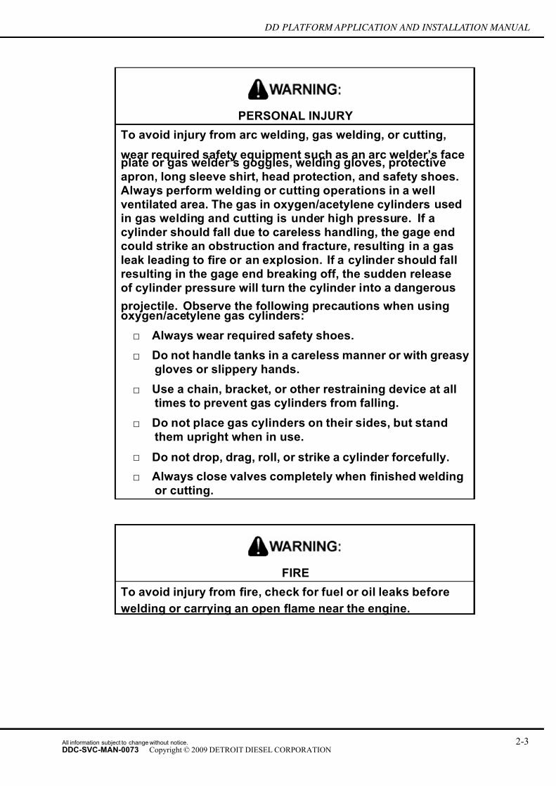
7/14/2019 Dd13-Dd15 a&i Manual
http://slidepdf.com/reader/full/dd13-dd15-ai-manual 27/304
DD PLATFORM APPLICATION AND INSTALLATION MANUAL
PERSONAL INJURY
To avoid injury from arc welding, gas welding, or cutting,
wear required safety equipment such as an arc welder’s faceplate or gas welder’s goggles, welding gloves, protective
apron, long sleeve shirt, head protection, and safety shoes.Always perform welding or cutting operations in a well
ventilated area. The gas in oxygen/acetylene cylinders used
in gas welding and cutting is under high pressure. If a
cylinder should fall due to careless handling, the gage endcould strike an obstruction and fracture, resulting in a gas
leak leading to fire or an explosion. If a cylinder should fallresulting in the gage end breaking off, the sudden release
of cylinder pressure will turn the cylinder into a dangerous
projectile. Observe the following precautions when usingoxygen/acetylene gas cylinders:
□ Always wear required safety shoes.
□ Do not handle tanks in a careless manner or with greasy
gloves or slippery hands.
□ Use a chain, bracket, or other restraining device at alltimes to prevent gas cylinders from falling.
□ Do not place gas cylinders on their sides, but stand
them upright when in use.
□ Do not drop, drag, roll, or strike a cylinder forcefully.
□ Always close valves completely when finished welding
or cutting.
FIRE
To avoid injury from fire, check for fuel or oil leaks before
welding or carrying an open flame near the engine.
All information subject to change without notice. 2-3DDC-SVC-MAN-0073 Copyright © 2009 DETROIT DIESEL CORPORATION

7/14/2019 Dd13-Dd15 a&i Manual
http://slidepdf.com/reader/full/dd13-dd15-ai-manual 28/304
SAFETY PRECAUTIONS
NOTICE:
When welding, the following must be done to avoid damage to theelectronic controls or the engine:
□ Both the positive (+) and negative (-) battery leads must be
disconnected before welding.
□ Ground cable must be in close proximity to welding location- engine must never be used as a grounding point.
□ Welding on the engine or engine mounted components isNEVER recommended.
2.5 WORK PLACE
Organize your work area and keep it clean.
PERSONAL INJURY
To avoid injury from slipping and falling, immediately clean
up any spilled liquids.
Eliminate the possibility of a fall by:
□ Wiping up oil spills
□ Keeping tools and parts off the floor
A fall could result in a serious injur y.
After installation of the engine is complete:
PERSONAL INJURY
To avoid injury from rotating belts and fans, do not removeand discard safety guards.
□ Reinstall all safety devices, guards or shields
□ Check to be sure that all tools and equipment used to install the engine are removed from
the engine
2-4 All information subject to change without notice.
DDC-SVC-MAN-0073 Copyright © 2009 DETROIT DIESEL CORPORATION

7/14/2019 Dd13-Dd15 a&i Manual
http://slidepdf.com/reader/full/dd13-dd15-ai-manual 29/304
DD PLATFORM APPLICATION AND INSTALLATION MANUAL
2.6 CLOTHING
Wear work clothing that fits and is in good repair. Work shoes must be sturdy and rough-soled.
Bare feet, sandals or sneakers are not acceptable foot wear when installing an engine.
PERSONAL INJURY
To avoid injury when working near or on an operating engine,remove loose items of clothing and jewelry. Tie back or
contain long hair that could be caught in any moving partcausing injury.
2.7 ELECTRIC TOOLS
Improper use of electrical equipment can cause severe injury.
ELECTRICAL SHOCK
To avoid injury from electrical shock, follow OEM furnishedoperating instructions prior to usage.
2.8 AIRUse proper shielding to protect everyone in the work area.
EYE INJURY
To avoid injury from flying debris when using compressed air,wear adequate eye protection (face shield or safety goggles)
and do not exceed 276 kPa (40 psi) air pressure.
2.9 FLUIDS AND PRESSURE
Be extremely careful when dealing with fluids under pressure. Fluids under pressure can have
enough force to penetrate the skin.
All information subject to change without notice. 2-5DDC-SVC-MAN-0073 Copyright © 2009 DETROIT DIESEL CORPORATION

7/14/2019 Dd13-Dd15 a&i Manual
http://slidepdf.com/reader/full/dd13-dd15-ai-manual 30/304
SAFETY PRECAUTIONS
These fluids can infect a minor cut or opening in the skin. See a doctor at once, if injured by
escaping fluid. Serious infection or reaction can result without immediate medical treatment.
PERSONAL INJURY
To prevent the escape of high pressure fuel that can penetrateskin, ensure the engine has been shut down for a minimum of
10 minutes before servicing any component within the high
pressure circuit. Residual high fuel pressure may be present
within the circuit.
HOT COOLANT
To avoid scalding from the expulsion of hot coolant, never
remove the cooling system pressure cap while the engine isat operating temperature. Wear adequate protective clothing
(face shield, rubber gloves, apron, and boots). Remove the
cap slowly to relieve pressure.
PERSONAL INJURY
To avoid injury from penetrating fluids, do not put your handsin front of fluid under pressure. Fluids under pressure can
penetrate skin and clothing.
2.10 BATTERIES
Electrical storage batteries give off highly flammable hydrogen gas when charging and continue
to do so for some time after receiving a steady charge.
Always disconnect the battery cable before working on the Detroit Diesel Electronic Controls
system.
2-6 All information subject to change without notice.
DDC-SVC-MAN-0073 Copyright © 2009 DETROIT DIESEL CORPORATION

7/14/2019 Dd13-Dd15 a&i Manual
http://slidepdf.com/reader/full/dd13-dd15-ai-manual 31/304
DD PLATFORM APPLICATION AND INSTALLATION MANUAL
Battery Explosion and Acid Burn
To avoid injury from battery explosion or contact with battery
acid, work in a well ventilated area, wear protective clothing,and avoid sparks or flames near the battery. If you come in
contact with battery acid:
□ Flush your skin with water.
□ Apply baking soda or lime to help neutralize the acid.
□ Flush your eyes with water.
□ Get medical attention immediately.
2.11 FIRE
Keep a charged fire extinguisher within reach. Be sure you have the correct type of extinguisher
for the situation. The correct fire extinguisher types for specific working environments are listed
in the following table.
Fire Extinguisher Work Environment
Type A Wood, Paper, Textile and Rubbish
Type B Flammable Liquids
Type C Electrical Equipment
Table 2-1 The Correct Type of Fire Extinguisher
2.12 FLUOROELASTOMER
Fluoroelastomer (Viton®) parts such as O-rings and seals are perfectly safe to handle under
normal design conditions.
A potential hazard may occur if these components are raised to a temperature above 316°C (600°F)
(in a fire for example). Fluoroelastomer will decompose (indicated by charring or the appearance
of a black, sticky mass) and produce hydrofluoric acid. This acid is extremely corrosive and, if
touched by bare skin, may cause severe burns (the symptoms could be delayed for several hours).
All information subject to change without notice. 2-7DDC-SVC-MAN-0073 Copyright © 2009 DETROIT DIESEL CORPORATION

7/14/2019 Dd13-Dd15 a&i Manual
http://slidepdf.com/reader/full/dd13-dd15-ai-manual 32/304
SAFETY PRECAUTIONS
CHEMICAL BURNS
To avoid injury from chemical burns, wear a face shield and
neoprene or PVC gloves when handling fluoroelastomer O-rings or seals that have been degraded by excessive heat.
Discard gloves after handling degraded fluoroelastomer parts.
2-8 All information subject to change without notice.
DDC-SVC-MAN-0073 Copyright © 2009 DETROIT DIESEL CORPORATION

7/14/2019 Dd13-Dd15 a&i Manual
http://slidepdf.com/reader/full/dd13-dd15-ai-manual 33/304
DD PLATFORM APPLICATION AND INSTALLATION MANUAL
3 ENGINE AND ACCESSORY IDENTIFICATION
Section Page
3.1 ENGINE AND ACCESSORY IDENTIFICATION DESCRIPTION ........... 3- 2
3.2 MAJOR COMPONENT LOCATIONS ...................................................... 3- 4
3.3 ENGINE IDENTIFICATION ..................................................................... 3- 5
All information subject to change without notice. 3-1DDC-SVC-MAN-0073 Copyright © 2009 DETROIT DIESEL CORPORATION

7/14/2019 Dd13-Dd15 a&i Manual
http://slidepdf.com/reader/full/dd13-dd15-ai-manual 34/304
ENGINE AND ACCESSORY IDENTIFICATION
3.1 ENGINE AND ACCESSORY IDENTIFICATIONDESCRIPTION
The DD Platform engines are a family of inline, six cylinder, four stroke engines. The DD15™
has a displacement of 2.47 liters per cylinder and total displacement of 14.8 liters. The DD13™
has a displacement of 2.13 liters per cylinder and total displacement of 12.8 liters. All DD
Platform engines use a separate Charge Air Cooling (CAC) system in addition to the conventionalJacket Water (JW) cooling system.
Figure 3-1 DD Platform On-Highway Engine
The DD Platform engine dual overhead cam design optimizes the intake and exhaust air passages
in the cylinder head for easier breathing. The cam follower roller in the injector rocker arm is
made of silicon nitride which makes it possible to operate at very high injection pressures while
maintaining long life of the roller.
The intake and exhaust port configuration of the DD Platform is unique. In this design, the
valve orientation has been rotated 90 degrees from the traditional arrangement used in push-rodengines. Other engines rotate the valves 45 degrees, to promote push-rod actuation. However, the
90 degree design provides several distinct advantages such as very short, unobstructed intake and
exhaust ports for ef ficient air flow, low pumping losses, and reduced heat transfer.
3-2 All information subject to change without notice.
DDC-SVC-MAN-0073 Copyright © 2009 DETROIT DIESEL CORPORATION
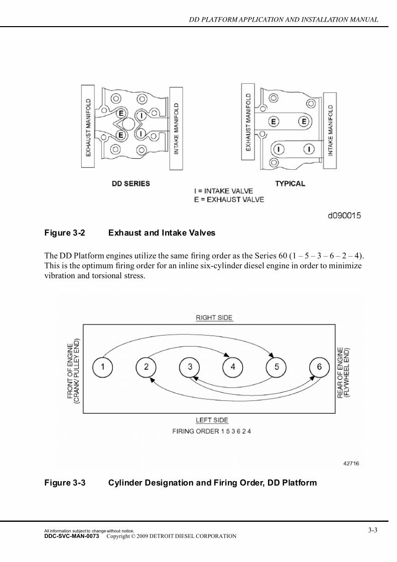
7/14/2019 Dd13-Dd15 a&i Manual
http://slidepdf.com/reader/full/dd13-dd15-ai-manual 35/304
DD PLATFORM APPLICATION AND INSTALLATION MANUAL
Figure 3-2 Exhaust and Intake Valves
The DD Platform engines utilize the same firing order as the Series 60 (1 – 5 – 3 – 6 – 2 – 4).
This is the optimum firing order for an inline six-cylinder diesel engine in order to minimize
vibration and torsional stress.
Figure 3-3 Cylinder Designation and Firing Order, DD Platform
All information subject to change without notice. 3-3DDC-SVC-MAN-0073 Copyright © 2009 DETROIT DIESEL CORPORATION

7/14/2019 Dd13-Dd15 a&i Manual
http://slidepdf.com/reader/full/dd13-dd15-ai-manual 36/304
ENGINE AND ACCESSORY IDENTIFICATION
3.2 MAJOR COMPONENT LOCATIONS
Any design variation of the components called out in the following illustrations may be found
on www.detroitdiesel.com, if you do not have access to www.detroitdiesel.com contact your
Distributor.
1. Exhaust Gas Recirculation Cooler 6.Starter location
2. EGR Valve / Actuator 7. Air Seal Pressure Regulator Valve
3. Axial Power Turbine 8. Crankcase Breather
4. Hydrocarbon Doser Valve 9. Turbocharger
5. APT Gearbox
Figure 3-4 Right Side Engine View
3-4 All information subject to change without notice.
DDC-SVC-MAN-0073 Copyright © 2009 DETROIT DIESEL CORPORATION

7/14/2019 Dd13-Dd15 a&i Manual
http://slidepdf.com/reader/full/dd13-dd15-ai-manual 37/304
DD PLATFORM APPLICATION AND INSTALLATION MANUAL
1. Waterpump 8. HC Doser Block Assembly
2. Oil / Coolant Module 9. Low Pressure Fuel Pump
3. Coolant Filter 10. Air Compressor
4. Oil Filter 11. Power Steering Pump
5. Fuel Rail (Behind Cover) 12.Fuel Filter Module
6. Intake Manifold 13. Motor Control Module
7. High Pressure Fuel Pump 14. Thermostat
Figure 3-5 Left Side Engine View
3.3 ENGINE IDENTIFICATION
The permanent engine serial number and model number are stamped on the cylinder block.
All information subject to change without notice. 3-5DDC-SVC-MAN-0073 Copyright © 2009 DETROIT DIESEL CORPORATION

7/14/2019 Dd13-Dd15 a&i Manual
http://slidepdf.com/reader/full/dd13-dd15-ai-manual 38/304
ENGINE AND ACCESSORY IDENTIFICATION
Figure 3-6 The Engine Serial Numbers Stamp and Model Number, DD Platform
The first six digits of the engine Serial Number are the Model Number, describing the engine
displacement and the intended market. The 472 indicates a (14.8L) DD15 engine while a 471
indicates a (12.8L) DD13 engine. There are a variety of market codes indicating engines intended
for use in the NAFTA, European or Asian markets.
Option labels and emission certification labels attached to the valve rocker cover contain the
engine serial and model numbers and list any optional equipment used on the engine
Figure 3-7 Rocker Cover with Option Label
The engine model number with serial number should be given with any order for parts. In
addition, if a type number is shown on the option plate covering the equipment required, this
number should also be included on the parts order.
3-6 All information subject to change without notice.
DDC-SVC-MAN-0073 Copyright © 2009 DETROIT DIESEL CORPORATION

7/14/2019 Dd13-Dd15 a&i Manual
http://slidepdf.com/reader/full/dd13-dd15-ai-manual 39/304
DD PLATFORM APPLICATION AND INSTALLATION MANUAL
All groups or parts used on a unit are standard for the engine model unless otherwise listed
on the option plate. For complete information on parts, refer to the DD15™ Parts Cat alog
(DDC-SVC-MAN-0042).
DD Platform engines may include additional information labels ordered in the 14B08 group.
All information subject to change without notice. 3-7DDC-SVC-MAN-0073 Copyright © 2009 DETROIT DIESEL CORPORATION

7/14/2019 Dd13-Dd15 a&i Manual
http://slidepdf.com/reader/full/dd13-dd15-ai-manual 40/304
ENGINE AND ACCESSORY IDENTIFICATION
THIS PAGE INTENTIONALLY LEFT BLANK
3-8 All information subject to change without notice.
DDC-SVC-MAN-0073 Copyright © 2009 DETROIT DIESEL CORPORATION

7/14/2019 Dd13-Dd15 a&i Manual
http://slidepdf.com/reader/full/dd13-dd15-ai-manual 41/304
DD PLATFORM APPLICATION AND INSTALLATION MANUAL
4 AIR INLET SYSTEM
Section Page
4.1 AIR INLET SYSTEM DESCRIPTION ...................................................... 4- 2
4.2 INSTALLATION REQUIREMENTS ......................................................... 4- 4
4.3 DESIGN GUIDELINES ............................................................................ 4-17
4.4 TESTING REQUIREMENTS ................................................................... 4-23
4.5 TEST ....................................................................................................... 4-25
All information subject to change without notice. 4-1DDC-SVC-MAN-0073 Copyright © 2009 DETROIT DIESEL CORPORATION

7/14/2019 Dd13-Dd15 a&i Manual
http://slidepdf.com/reader/full/dd13-dd15-ai-manual 42/304
AIR INLET SYSTEM
4.1 AIR INLET SYSTEM DESCRIPTION
An internal combustion engine requires an adequate supply of air for combustion to develop full
rated power and burn fuel ef ficiently. This section describes the function, installation, design, and
test requirements for the air inlet system of a Detroit Diesel DD Platform engine.
The intake manifold routes the air charge into the cylinder head ports through two intake valves,
and into the cylinder. At the beginning of the compression stroke, each cylinder is filled with a
mixture of clean, fresh air and recirculated exhaust gas, which provides for ef ficient combustion
while reducing the formation of NOx. The turbocharger supplies air under pressure to the Charge
Air Cooler (CAC) and then to the intake manifold. The recirculated exhaust gas is extracted from
the exhaust manifold, cooled by a gas to water EGR Cooler, routed through the EGR cold pipe and
venturi, and then mixed with fresh, cooled air from the CAC. The air enters the turbocharger after
passing through the air cleaner or air silencer. Power to drive the turbocharger is extracted from
energy in the engine exhaust gas. The expanding exhaust gases turn a single stage turbocharger
wheel, which drives an impeller, thus pressurizing intake air. This charge air is then cooled by an
air-to-air CAC before flowing into the cylinders for improved combustion ef ficiency.
4.1.1 DD PLATFORM ON-HIGHWAY ENGINES
All DD Platform on-highway engines have a single turbocharger which supplies filtered air
through a CAC to the air intake manifold. The CACs are generally located in front of or next
to the engine radiator core.
The inlet manifold options available may be found on www.detroitdiesel.com, if you do not have
access to www.detroitdiesel.com contact your Distributor.
4-2 All information subject to change without notice.
DDC-SVC-MAN-0073 Copyright © 2009 DETROIT DIESEL CORPORATION

7/14/2019 Dd13-Dd15 a&i Manual
http://slidepdf.com/reader/full/dd13-dd15-ai-manual 43/304
DD PLATFORM APPLICATION AND INSTALLATION MANUAL
1.Cold Boost Pipe 3. EGR Cooler
2. Intake Manifold A97. EGR Actuator
Figure 4-1 Air Intake System Schematic – On-Highway
A CAC is typically mounted ahead of the engine coolant radiator. The pressurized intake charge
is routed from the discharge side of the turbocharger, through the CAC, through the air throttle
and combined with recirculated exhaust gas in the intake manifold which directs the air to
ports in the cylinder head, through two intake valves per cylinder, and into the cylinder. At the
beginning of the compression stroke, each cylinder is filled with a mixture of clean, cooled air and
recirculated exhaust gas. The intake manifold air inlet is attached to the CAC ducting and the air
compressor using flexible hose and clamps.
All information subject to change without notice. 4-3DDC-SVC-MAN-0073 Copyright © 2009 DETROIT DIESEL CORPORATION

7/14/2019 Dd13-Dd15 a&i Manual
http://slidepdf.com/reader/full/dd13-dd15-ai-manual 44/304
AIR INLET SYSTEM
1. Intake Manifold Gasket 7. Throttle Adapter
2. Grid Heater 8. Gasket
3. O-ring 9. Intake Throttle Valve
4. Cold Boost Pipe 10. Gasket
5. Intake Manifold Pressure Sensor 11. EGR Temperature Sensor
6. Gasket 12. Intake Manifold
Figure 4-2 Intake Manifold and Related Parts
4.2 INSTALLATION REQUIREMENTS
The air inlet system has a direct effect on engine output, fuel consumption, exhaust emissions,
and engine life. The parts and materials must be designed to withstand the working environment
that applies to the system.
4-4 All information subject to change without notice.
DDC-SVC-MAN-0073 Copyright © 2009 DETROIT DIESEL CORPORATION

7/14/2019 Dd13-Dd15 a&i Manual
http://slidepdf.com/reader/full/dd13-dd15-ai-manual 45/304
DD PLATFORM APPLICATION AND INSTALLATION MANUAL
4.2.1 DRY PAPER ELEMENT AIR CLEANERS
Dry paper element type cleaners are recommended for use on Detroit Diesel engines. Alternate
types of air filtration systems, such as foam type and oil bath cleaners may be available in the
aftermarket.
Dry paper element air cleaners are classified by function:
□ Light-duty air cleaners
□ Medium-duty air cleaners
□ Heavy-duty air cleaners
□ Extra heavy-duty air cleaners
The type of function relates to the dust holding capacity of the particular cleaner. The choice of
cleaner depends upon the engine type, application, operating environment, and service life. The
cleaner must meet filtration requirements across the engine speed and load range and be readily
accessible for maintenance with adequate space provision for replacement. Air cleaners may have
replaceable elements, or may be completely disposable. The different types of air cleaners and theapplication in which they are used are listed in the following table.
Type of Air Cleaners Application
Light-dutyMarine engines, mobile and stationary engines in factories,
warehouses, etc. and cranes (wheel-mounted)
Medium-dutyStationary engines, air compressors, pumps, and cranes
(wheel-mounted)
Heavy-duty
Trucks (nonroad, logging), tractors (wheel, agricultural) also
tractors (crawler, small), motor graders, scrapers, cranes
(shovels), stationary engines in dusty ambients
Extra Heavy-duty
Scrapers (large or rear engine), rock dril ls (self-contained),
cranes and shovels (rough terrain), air compressors ( rock
drilling or quarrying), tractors (full-tracked, low speed), stationaryengines in extreme dust
Table 4-1 Air Cleaner Applications
Tests to determine the service life of an air cleaners are usually performed in accordance with
SAE J726-C.
4.2.1.1 Light-Duty Air Cleaner
Typical light-duty air cleaner.
All information subject to change without notice. 4-5DDC-SVC-MAN-0073 Copyright © 2009 DETROIT DIESEL CORPORATION

7/14/2019 Dd13-Dd15 a&i Manual
http://slidepdf.com/reader/full/dd13-dd15-ai-manual 46/304
AIR INLET SYSTEM
Figure 4-3 Light-Duty Air Cleaner, Single Stage Cartridge Type
4.2.1.2 Medium-Duty Use Air Cleaner
A medium-duty air cleaner is typically a two stage cyclonic/paper element cleaner. These cleaners
have a cyclonic first stage that removes about 80-85% of the dust from the air before it passes
through the paper element. Optional safety elements for increased reliability are available and
may be included in these air cleaners.
4-6 All information subject to change without notice.
DDC-SVC-MAN-0073 Copyright © 2009 DETROIT DIESEL CORPORATION

7/14/2019 Dd13-Dd15 a&i Manual
http://slidepdf.com/reader/full/dd13-dd15-ai-manual 47/304
DD PLATFORM APPLICATION AND INSTALLATION MANUAL
1. Body Assembly 6. Primary Element
2. Vacuator Valve 7. Safety Element
3. Cup Assembly 8. Nut Assembly (Wing Nut and Washer Gasket)
4. Clamp Assembly 9. Restriction Indicator Fitting Cap
5. Baf fle Assembly 10. O-ring
Figure 4-4 Medium-Duty Air Cleaner
4.2.1.3 Heavy-Duty Use Air Cleaner
A heavy-duty air cleaner is typically a two stage cyclonic/paper element cleaner. These cleaners
incorporate a highly ef ficient cyclonic pre-cleaner arrangement that removes 94-98% of the dust
from the air before it passes through the paper element. Some types of heavy duty air cleaners
do not include a mechanical precleaner but employ an oversized cleaner element to accomplish
the same dust removal with similar service intervals. Optional safety elements for increased
reliability are available and may be included in these air cleaners.
All information subject to change without notice. 4-7DDC-SVC-MAN-0073 Copyright © 2009 DETROIT DIESEL CORPORATION

7/14/2019 Dd13-Dd15 a&i Manual
http://slidepdf.com/reader/full/dd13-dd15-ai-manual 48/304
AIR INLET SYSTEM
1. Dust Cup 8. Safety Element
2. Cup Clamp 9. Safety Signal
3. Body or Cup O-ring 10. Primary Element
4. Lower Body Assembly 11. Gasket
5. Body Clamp 12. Access Cover
6. O-ring 13. Wing Nut
7. Upper Body Assembly
Figure 4-5 Heavy-Duty Air Cleaner
4-8 All information subject to change without notice.
DDC-SVC-MAN-0073 Copyright © 2009 DETROIT DIESEL CORPORATION
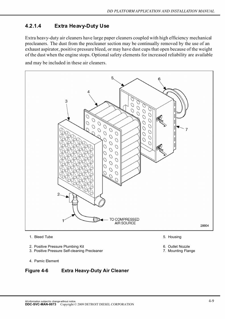
7/14/2019 Dd13-Dd15 a&i Manual
http://slidepdf.com/reader/full/dd13-dd15-ai-manual 49/304
DD PLATFORM APPLICATION AND INSTALLATION MANUAL
4.2.1.4 Extra Heavy-Duty Use
Extra heavy-duty air cleaners have large paper cleaners coupled with high ef ficiency mechanical
precleaners. The dust from the precleaner section may be continually removed by the use of an
exhaust aspirator, positive pressure bleed, or may have dust cups that open because of the weight
of the dust when the engine stops. Optional safety elements for increased reliability are available
and may be included in these air cleaners.
1. Bleed Tube 5. Housing
2. Positive Pressure Plumbing Kit 6. Outlet Nozzle3. Positive Pressure Self-cleaning Precleaner 7. Mounting Flange
4. Pamic Element
Figure 4-6 Extra Heavy-Duty Air Cleaner
All information subject to change without notice. 4-9DDC-SVC-MAN-0073 Copyright © 2009 DETROIT DIESEL CORPORATION

7/14/2019 Dd13-Dd15 a&i Manual
http://slidepdf.com/reader/full/dd13-dd15-ai-manual 50/304
AIR INLET SYSTEM
4.2.1.5 Foam Type Air Cleaners
Foam type air cleaner elements, available in the aftermarket, may produce gummy or varnish-like
deposits which may affect engine operation.
NOTICE:
Detroit Diesel is aware of attempts to use air cleaner elementsmade of foam or fabric batting material soaked with a stickysubstance to improve dirt-holding capability. This substance may
transfer from the cleaner media and coat the inside surfaces of air ducts and engine air inlet systems, blowers, and air boxes.
The result may be reduced engine performance and a changein engine operating conditions.
Detroit Diesel does not recommend the use of foam type air cleaners, in any application.
4.2.1.6 Oil-bath Air Cleaners
Use of an oil-bath air cleaner is not recommended. Oil-bath type air cleaners generally do not
have enough gradability for mobile, nonroad applications.
NOTICE:
Air cleaner performance may be adversely affected by temperature
extremes. Oil pullover from impr oper usage or extreme vehicle
tilt may cause engine runaway and damage. The oil mistcreated by the cleaner may adversely effect turbocharger life and
performance.
Oil-bath air cleaners generally have lower ef ficiencies and greater restriction to air flow than
dry type air cleaners.
Detroit Diesel recognizes that oil bath air cleaners may be necessary in locations where dry type air
cleaners are not readily available. Therefore, oil-bath type air cleaners are acceptable when used
according to the air cleaner manufacturer's guidelines and Detroit Diesel air system requirements.
Prior approval from Detroit Diesel Application Engineering is required if an oil-bath air cleaner
is needed.
4.2.1.7 Auxiliary Precleaners
Auxiliary precleaners are devices that separate contaminants from the incoming air and expel
them through a discharge port prior to entering the air cleaner inlet. Precleaners remove most
of the airborne dirt from incoming air which extends the service life of the cleaner element.
Precleaners f orce the incoming air to rotate within the precleaner creating a centrifugal force and
depositing the dirt into a bin or cup for removal while servicing.
4-10 All information subject to change without notice.
DDC-SVC-MAN-0073 Copyright © 2009 DETROIT DIESEL CORPORATION

7/14/2019 Dd13-Dd15 a&i Manual
http://slidepdf.com/reader/full/dd13-dd15-ai-manual 51/304
DD PLATFORM APPLICATION AND INSTALLATION MANUAL
Figure 4-7 Precleaner Centrifugal Action
Precleaners may be used with the DD Platform engines as long as the air inlet restriction
requirements are met. The use of a precleaner may necessitate the use of a larger air cleaner.
4.2.1.8 Inlet Screens
An inlet screen may be used with an air cleaner when larger airborne material is encountered in
an operating environment. An inlet screen will prevent this material from blocking air passage
through the air cleaner elements. The inlet screen should be inspected frequently and cleaned as
necessary.
4.2.1.9 Rain Caps and Inlet Hoods
The entrance to the air cleaner must be designed to ensure that no water or snow can enter the
air cleaner. Rain caps or inlet hoods are used for this purpose.
All information subject to change without notice. 4-11DDC-SVC-MAN-0073 Copyright © 2009 DETROIT DIESEL CORPORATION

7/14/2019 Dd13-Dd15 a&i Manual
http://slidepdf.com/reader/full/dd13-dd15-ai-manual 52/304
AIR INLET SYSTEM
Figure 4-8 Rain Cap and Inlet Hood
4.2.1.10 Water Drains
Water injection is possible with most intake systems, either by unexpected operating conditions
or failures in the intake parts. A water drain should be positioned at the lowest point in the
system. A water collection trap may be necessary to overcome engine vacuum. Drains may also
be needed on the bottom of the air cleaner.
NOTICE:
Excessive water injection may cause severe engine damage or complete failure.
4.2.1.11 Inlet Silencers
Appreciable reductions in noise levels can sometimes be achieved with the use of inlet silencers.
The installer should consult the supplier for specific recommendations. Care should be taken to
ensure that the intake restriction is not raised above the allowable limit for clean air cleaners.
4.2.1.12 Air Cleaner Selection
Choose an appropriate air cleaner as follows:
1. Determine the maximum engine air flow requirement and the clean and dirty
restriction limitations found on www.detroitdiesel.com, if you do not have access to
www.detroitdiesel.com contact your Distributor.
4-12 All information subject to change without notice.
DDC-SVC-MAN-0073 Copyright © 2009 DETROIT DIESEL CORPORATION

7/14/2019 Dd13-Dd15 a&i Manual
http://slidepdf.com/reader/full/dd13-dd15-ai-manual 53/304
DD PLATFORM APPLICATION AND INSTALLATION MANUAL
2. Determine the general application category.
3. Determine the air cleaner classification.
4. Select the appropriate cleaner from the manufacturer's recommendations.
4.2.2 RESTRICTION INDICATOR
Air inlet restriction is an important parameter of the air inlet system. High inlet restriction may
cause insuf ficient air for combustion. Factors resulting in a high inlet restriction include:
□ Small intake pipe diameter
□ Excessive number of sharp bends in system
□ Long pipe between the air cleaner and turbocharger compressor inlet
□ High air cleaner resistance
Air inlet restriction that is too high may result in:
□
Reduced power □ Poor fuel economy
□ High combustion temperature
□ Over-heating
□ Reduced engine life
An air inlet restriction indicator must be fitted on the air intake system.
The operating setting of the indicator should corr espond to the maximum permissible inlet
restriction, 5.0 kPa (20 in. H2O) maximum for systems with dirty cleaners, provided that it is
connected to a tapping point close to the turbocharger inlet.
Altitude affects air inlet restriction The Altitude Performance Curve illustrates the effects of
altitude on the percentage of inlet restriction.
All information subject to change without notice. 4-13DDC-SVC-MAN-0073 Copyright © 2009 DETROIT DIESEL CORPORATION

7/14/2019 Dd13-Dd15 a&i Manual
http://slidepdf.com/reader/full/dd13-dd15-ai-manual 54/304
AIR INLET SYSTEM
Figure 4-9 Altitude vs. Inlet Restriction
An example of the reduction of allowable restriction at different altitudes is listed in the following
table.
4-14 All information subject to change without notice.
DDC-SVC-MAN-0073 Copyright © 2009 DETROIT DIESEL CORPORATION

7/14/2019 Dd13-Dd15 a&i Manual
http://slidepdf.com/reader/full/dd13-dd15-ai-manual 55/304
DD PLATFORM APPLICATION AND INSTALLATION MANUAL
Allowable Restriction
Clean System Dirty System
25°C (77°F) 3.0 kPa (12 in. H2O) 5.0 kPa (20 in. H
2O) At sea level
25°C (77°F) 2.31 kPa (9.25 in. H2O) 3.85 kPa (15.5 in. H
2O)
2,438 m (8,000 ft.)
above sea level
Table 4-2 Air Inlet Restriction at Different Altitudes
The reason for this reduction in allowable restriction is the lower air density at altitude.
Install the restriction indicator as close to the turbocharger compressor inlet as practical, but no
closer than 12.7 cm (5 in.).
Compensate for the added restriction incurred from piping between the cleaner and the
turbocharger inlet when the restriction indicator fits to the air cleaner tapping of a remote-mounted
cleaner.
4.2.3 PIPEWORK
Give careful attention to the pipework and associated fittings used in the inlet system in order to
minimize restriction and maintain reliable sealing.
Keep piping lengths short to minimize the number of bends and restriction incurred in the system.
Use smooth bend elbows with a bend radius to tube diameter (R/D) ratio of at least 2.0 and
preferably 4.0.
Keep air ducts away from heat sources such as exhaust manifolds, etc. Use appropriate insulation
or shielding to minimize radiated heat from these sources to the inlet system.
4.2.3.1 Pipework Material Specifications
Aluminum or aluminized steel seamless tubing should be used. The tube ends require a 0.09 in.
(2.3 mm) minimum bead to retain hose and clamp connections.
Fiberglass piping between the air cleaner and the turbocharger compressor inlet is also acceptable.
Detroit Diesel recommends that mitered elbows should have multiple sections for a smooth
transition.
4.2.3.2 Diffusers
Make any necessary cross-sectional changes in the piping diameter gradually rather than using
sudden expansions or contractions.
All information subject to change without notice. 4-15DDC-SVC-MAN-0073 Copyright © 2009 DETROIT DIESEL CORPORATION

7/14/2019 Dd13-Dd15 a&i Manual
http://slidepdf.com/reader/full/dd13-dd15-ai-manual 56/304
AIR INLET SYSTEM
Figure 4-10 Acceptable Diffuser Configurations
4.2.4 HOSE CONNECTIONS
Use the following for hose connections:
□ Plain (non reinforced) hose sections to connect items of rigid pipework which are in line
and close together, or have little relative motion.
□ A short section of reinforced hose between the ductwork sections where significant relative
motion or misalignment occurs. High quality “Hump" hose is capable of meeting theserequirements.
□ Spring loaded clamps to provide positive clamping and to prevent piping separation.
Detroit Diesel does not approve the use of plain bore hoses with internal coil spring insertions.
Plain hoses used in the inlet system must be of adequate specification to withstand service
conditions. The basic requirements are listed in the following table.
Service Conditions Basic Requirements
Hose Material Synthetic Rubber
Oil Resistance
Resistant to fuel oil and lubricating oil on
both internal and external surfaces
Maximum Working Temperatures 105°C (220°F)
Working PressureUp to 1d2.5 kPa (50 in. H
2O) depression
(negative pressure)
Table 4-3 Hose Specifications for the Inlet Side of the Turbocharger
4-16 All information subject to change without notice.
DDC-SVC-MAN-0073 Copyright © 2009 DETROIT DIESEL CORPORATION

7/14/2019 Dd13-Dd15 a&i Manual
http://slidepdf.com/reader/full/dd13-dd15-ai-manual 57/304
DD PLATFORM APPLICATION AND INSTALLATION MANUAL
4.3 DESIGN GUIDELINES
The installed inlet system must be designed to supply clean, dry, cool air to the engine with
minimum restriction. The system must also provide reliable sealing, durability, and require
minimal maintenance.
NOTICE:Never allow the turbocharger to support any weight of the air
intake system.
The main design criteria for the air intake system includes:
□ Maximum air inlet flow
□ Air intake restriction
□ Inlet location
□ Temperature rise from ambient to turbo inlet
Refer to www.detroitdiesel.com, for limits on each of these criteria for your specific engine.
NOTE:
If you do not have access to www.detroitdiesel.com Contact your Distributor.
4.3.1 MAXIMUM AIR INLET FLOW
The first step in the design of the air inlet system is to determine the maximum air flow requirement
for the engine. This information for the DD Platform engines is listed on www.detroitdiesel.com.
NOTE:If you do not have access to www.detroitdiesel.com contact your Distributor.
4.3.2 AIR INLET SYSTEM RESTRICTION
Recommended pipe sizes may be used for the initial sizing of the air inlet system. Increase the pipe
size or modify the piping configuration if the air intake restriction exceeds the maximum limit.
An air inlet restriction indicator must be installed on the air intake system.
The worse case scenario for air inlet system restriction can be estimated by adding up the sum
of the individual restrictions in the system. These include rain caps, inlet hoods, air cleaners,
and piping.
All information subject to change without notice. 4-17DDC-SVC-MAN-0073 Copyright © 2009 DETROIT DIESEL CORPORATION

7/14/2019 Dd13-Dd15 a&i Manual
http://slidepdf.com/reader/full/dd13-dd15-ai-manual 58/304
AIR INLET SYSTEM
Figure 4-11 Air Inlet System Calculation
4.3.3 INLET LOCATION
Position the air cleaner inlet so that air is drawn from an area clear of water splash with the lowest
possible dust concentration; an area that minimizes:
□ The temperature rise from ambient to turbo inlet
□ The possibility of exhaust fumes and raw crankcase emissions being drawn into the inlet
system
4.3.4 AIR-TO-AIR CHARGE AIR COOLER
Suf ficient charge air cooling capability is required for optimum engine performance. Exceeding
the system limits may adversely affect the fuel economy, power, emissions, and durability.
For on-highway engines the CAC is normally mounted ahead of the cooling system radiator.
4-18 All information subject to change without notice.
DDC-SVC-MAN-0073 Copyright © 2009 DETROIT DIESEL CORPORATION

7/14/2019 Dd13-Dd15 a&i Manual
http://slidepdf.com/reader/full/dd13-dd15-ai-manual 59/304
DD PLATFORM APPLICATION AND INSTALLATION MANUAL
Figure 4-12 Typical Radiator-mounted Charge Air Cooling System Right Side
View
Figure 4-13 Typical Radiator-Mounted Charge Air Cooling System Left Side
View
The air-to-air charge cooling (A/ACC) system should be designed for the highest horsepower
engine offered in the application.
The same system can be used for derated versions of the engine, which offers the following
advantages:
All information subject to change without notice. 4-19DDC-SVC-MAN-0073 Copyright © 2009 DETROIT DIESEL CORPORATION

7/14/2019 Dd13-Dd15 a&i Manual
http://slidepdf.com/reader/full/dd13-dd15-ai-manual 60/304
AIR INLET SYSTEM
□ Reduce the number of components in the manufacturing and part systems
□ Lower power engines may achieve even greater fuel economy from the additional reduction
in engine intake air temperature
□ Extended engine life
The following guidelines will assist in the design and selection of the various components that
make up the A/ACC system. It is critical that these components offer maximum air temperaturereduction with minimal loss of air flow. The integrity of the components must provide for long
life in its operating environment.
The pipework and hose connection requirements for the A/ACC system are similar to those for
the air inlet system in general. Seamless, aluminum or aluminized steel should be used. The tube
ends require a 0.09 in. (2.3 mm) minimum bead to retain hose a nd clamp connections.
Air system operating parameters such as heat rejection, engine air flow, air pressure, maximum
pressure drop, minimum temperature loss, and turbocharger compressor discharge temperature
are available on the on www.detroitdiesel.com.
NOTE:If you do not have access to www.detroitdiesel.com, contact your distributor.
Charge air cooler considerations include size, cooling air flow restriction, material specifications,
header tanks, location, and fan systems.
4.3.4.1 Restriction and Temperature Requirements
Make special consideration for the air flow restriction which exists between the turbocharger
compressor outlet and intake manifold inlet for engines requiring a charge air cooler. The
maximum allowable pressure drop, including charge air cooler and piping, is 14 kPa (3.0 in. Hg)
at full load and rated speed. Refer to www.detroitdiesel.com for exceptions.
Core selection and location must meet charge air system temperature and pressure drop limits,
and must be compatible for good coolant radiator performance. Charge air coolers have a cooling
air flow restriction typically between 0.19 and 0.37 kPa (0.75 and 1.5 in. H2O).
It is recommended that the charge air cooler system be constructed using 5.0 in. diameter piping
with smooth radius bends.
The maximum temperature differential between ambient air and intake manifold is available
on www.detroitdiesel.com.
NOTE:
If you do not have access to www.detroitdiesel.com, contact your distributor.
4.3.4.2 Cleanliness
All new air charge cooling system components must be thoroughly clean and free of any casting
slag, core sand, welding slag, etc. or any that may break free during operation. These foreign
particles can cause serious engine damage.
4-20 All information subject to change without notice.
DDC-SVC-MAN-0073 Copyright © 2009 DETROIT DIESEL CORPORATION

7/14/2019 Dd13-Dd15 a&i Manual
http://slidepdf.com/reader/full/dd13-dd15-ai-manual 61/304
DD PLATFORM APPLICATION AND INSTALLATION MANUAL
4.3.4.3 Leakage
Leaks in the air-to-air cooling system can cause a loss in power, excessive smoke and high
exhaust temperature due to a loss in boost pressure. Large leaks can possibly be found visually,
while small heat exchanger leaks will have to be found using a pressure loss leak test.
PRESSURIZED CHARGE COOLER SYSTEM
To avoid eye or face injury from flying debris, wear a faceshield or goggles.
Check for leaks as follows:
1. Disconnect the charge air cooler.
2. Plug the inlet and outlet.
3. Measure pressure loss using an adaptor plug on the inlet.
The charge air cooler is considered acceptable if it can hold 172 kPa (25 psi) pressure with less
than a 34.5 kPa (5 psi) loss in 15 seconds after turning off the hand valve.
4.3.4.4 Size
The size of the heat exchanger depends on performance requirements, cooling air flow available,
and usable frontal area. Using the lar gest possible frontal area usually results in the most ef ficient
core with the least amount of system pressure drop. Consult your supplier to determine the proper
heat exchanger for your application. Refer to appendix for a list of suppliers.
4.3.4.5 Cooling Air Flow Restriction
Core selection and location must meet charge air system temperature and pressure drop limits,
and must be compatible for good coolant radiator performance. Charge air coolers have a cooling
air flow restriction typically between 0.19 and 0.37 kPa (0.75 and 1.5 in. H2O).
4.3.4.6 Material
Most charge air cooler s are made of aluminum alloys because of their light weight, costadvantages and good heat transfer characteristics. Other materials may be used with approval
from Detroit Diesel Application Engineering.
All information subject to change without notice. 4-21DDC-SVC-MAN-0073 Copyright © 2009 DETROIT DIESEL CORPORATION

7/14/2019 Dd13-Dd15 a&i Manual
http://slidepdf.com/reader/full/dd13-dd15-ai-manual 62/304
AIR INLET SYSTEM
4.3.4.7 Header Tanks
Header tanks should be designed for minimum pressure loss, uniform air flow distribution across
the core, and be strong enough to take pressure associated with turbocycling. Rounded corners and
smooth interior surfaces provide a smooth transition of the air flow resulting in minimum pressure
loss. The inlet and outlet diameters of the header tanks should be the same as the pipework to and
from the engine. A 4 in. (102 mm) minimum diameter is required for the DD Platform engines.The tube ends require a 0.09 in. (2.3 mm) minimum bead to retain hose and clamp connections.
4.3.4.8 Location
To have the coolest possible air, the cooler is typically mounted (upstream of air flow) or
along side the engine coolant radiator. Other locations are acceptable as long as performance
requirements are met. The cooler should be located as close to the engine as practical to minimize
pipe length and pressure losses.
Leave access space between the cores when stacked in front of one another so debris may be
removed.
4.3.4.9 Fan Systems
The fan system must provide suf ficient air flow to cool both the air-to-air heat exchanger as well
as the engine coolant radiator under all operating conditions.
A controlled fan drive system must be able to maintain a required air and water temperature.
DDEC controlled fan systems are PWM and drive clutch controlled.
A fan drive clutch with controls that sense engine coolant out temperature is the most suitable
for air-to-air installations. Viscous and modulating fan drives which sense down stream radiator
air out temperatures are not recommended.
4.3.4.10 Shutters
Shutters are not required under most operating conditions with a properly designed cooling
system. Improperly installed or maintained devices may lead to reduced engine life, loss of
power, and poor fuel economy.
NOTE:
It is imperative that all warning and shutdown monitoring devices be properly locatedand always in good operating condition.
Shutters must always be mounted downstream of the air-to-air heat exchanger and should open
approximately 2.8°C (5°F) before the thermostat start to open temperature. The shutter control
should sense engine water out (before thermostat) temperature and the probe be fully submerged
in coolant flow.
4-22 All information subject to change without notice.
DDC-SVC-MAN-0073 Copyright © 2009 DETROIT DIESEL CORPORATION

7/14/2019 Dd13-Dd15 a&i Manual
http://slidepdf.com/reader/full/dd13-dd15-ai-manual 63/304
DD PLATFORM APPLICATION AND INSTALLATION MANUAL
4.3.4.11 Winterfronts
Winterfronts are not required under most operating conditions with a properly designed cooling
system. Some operators reduce the air flow through the radiator during cold weather operation
to increase engine operating temperature. Consider on/off fans and shutters if long term idling
during severe cold weather is necessary.
Improperly used winterfronts may cause excessive temperatures of coolant, oil, and charge air.
This condition can lead to reduced engine life, loss of power, and poor fuel economy. Winterfronts
may also put abnormal stress on the fan and fan drive components.
Never totally close or apply the winterfront directly to the radiator core. At least 25% of the area
in the center of the grill should remain open at all times. All monitoring, warning, and shutdown
devices should be properly located and in good working condition.
4.4 TESTING REQUIREMENTS
A thorough evaluation of the air inlet system will include:
□ Complete descriptions and documentation of the system in the Vehicle Sign-Off forms
□ Adequate instrumentation
□ Proper test preparation
□ Accurate tests
□ Data analysis and documentation
□ Diagnostics (troubleshooting) and corrective action (if necessary)
These tests must be run on all new installations, engine repowers, or whenever modifications have
been made to the engine, air inlet system, engine load, duty cycle, or environmental operating
conditions. The Detroit Diesel Vehicle Sign-Off form must be completed.
4.4.1 TESTING LOCATION
This section describes the methods needed to measure the temperatures and pressures of air
inlet systems.
Location of temperature and pressure measurements needed to evaluate the air inlet system with
air-to-air charge cooling is shown.
All information subject to change without notice. 4-23DDC-SVC-MAN-0073 Copyright © 2009 DETROIT DIESEL CORPORATION

7/14/2019 Dd13-Dd15 a&i Manual
http://slidepdf.com/reader/full/dd13-dd15-ai-manual 64/304
AIR INLET SYSTEM
Figure 4-14 Typical Instrumentation Location
4.4.2 INLET SYSTEM RESTRICTION
The maximum permitted inlet restriction for a system with a clean air cleaner is 3 kPa (12 in. H2O).
The maximum permitted inlet restriction for a system with a dirty air cleaner is 5 kPa (20 in. H2O).
4.4.3 AIR-TO-AIR SYSTEM EVALUATION TESTS
The A/ACC system must be tested to verify that engine air intake temperatures and pressure
drop limits can be met as shown on www.detroitdiesel.com, if you do not have access to
www.detroitdiesel.com contact your Distributor. This evaluation can be done simultaneously
with the engine cooling index test.
4.4.3.1 Maximum Temperature Rise–Ambient to Intake Manifold
The maximum temperature differential between the ambient temperature and the temperature at
the intake manifold needs to be determined.
Symbol Measurement Location Description
T1
Air inlet temperature Within 5 in. of the turbocharger
T2
Compressor discharge
temperatureWithin 5 in. of the compressor outlet
T3
Intake manifold temperature Within 5 in. of the inlet connection
T4
- T8
Charge air cooler core air inlet
temperature
5 points in front of the core, one in the center and
one at each corner for determining recirculation
Table 4-4 Thermocouples
4-24 All information subject to change without notice.
DDC-SVC-MAN-0073 Copyright © 2009 DETROIT DIESEL CORPORATION

7/14/2019 Dd13-Dd15 a&i Manual
http://slidepdf.com/reader/full/dd13-dd15-ai-manual 65/304
DD PLATFORM APPLICATION AND INSTALLATION MANUAL
These temperature restrictions for the DD Platform engines are listed on www.detroitdiesel.com,
if you do not have access to www.detroitdiesel.com contact your Distributor.
4.4.3.2 Charge Air Cooler System Restriction
The maximum pressure differential of the charge air cooler system results from the charge air
cooler and all of the piping and connections between the turbocharger compressor outlet andthe intake manifold.
Symbol Measurement Location Description
P1
Air inlet restrictionWithin 5 in. of the turbocharger, in a straight section
after the last bend
P2
Compressor discharge pressureWithin 5 in. of the turbocharger, in a straight section
before the first bend
P3
Intake manifold pressureWithin 5 in. of the inlet connection in a straight
section after the last bend (or in the manifold itself)
Table 4-5 Pressure Taps
Connect a precision gage between pressure taps P2
and P3
to determine pressure drop of the
system. Two precision gages may be used as desired.
The maximum pressure drop for the DD Platform engines is shown on www.detroitdiesel.com, if
you do not have access to www.detroitdiesel.com contact your Distributor.
4.5 TEST
Thorough preparations prior to testing will ensure accurate results.
□ Confirm all instrumentation and equipment is in good working condition and calibrated.
□ Tests should be run on a finalized package installed in unit or vehicle representative of
the final package to be released.
□ Shutters must be fully opened and fan drive mechanisms in the fully engaged position.
All A/ACC tests should be performed with the engine operating at maximum rated speed and
wide open throttle (full fuel).
4.5.1 MOBILE AIR-TO-AIR
Refer to www.detroitdiesel.com, for the appropriate ram air speed to be used for testing. Other
mobile applications require appropriate ram air. In some mobile applications no ram air should beapplied. Sample data sheets for the air inlet and charge air system tests are given below.
NOTE:
If you do not have access to www.detroitdiesel.com contact your Distributor.
All information subject to change without notice. 4-25DDC-SVC-MAN-0073 Copyright © 2009 DETROIT DIESEL CORPORATION

7/14/2019 Dd13-Dd15 a&i Manual
http://slidepdf.com/reader/full/dd13-dd15-ai-manual 66/304
AIR INLET SYSTEM
Figure 4-15 Air Inlet Data Sheet for Turbocharged and Air-to-Air Charge Cooled
Engine
4-26 All information subject to change without notice.
DDC-SVC-MAN-0073 Copyright © 2009 DETROIT DIESEL CORPORATION

7/14/2019 Dd13-Dd15 a&i Manual
http://slidepdf.com/reader/full/dd13-dd15-ai-manual 67/304
DD PLATFORM APPLICATION AND INSTALLATION MANUAL
Figure 4-16 Air Inlet System Data Sheet for Turbocharged Engines
All information subject to change without notice. 4-27DDC-SVC-MAN-0073 Copyright © 2009 DETROIT DIESEL CORPORATION

7/14/2019 Dd13-Dd15 a&i Manual
http://slidepdf.com/reader/full/dd13-dd15-ai-manual 68/304
AIR INLET SYSTEM
THIS PAGE INTENTIONALLY LEFT BLANK
4-28 All information subject to change without notice.
DDC-SVC-MAN-0073 Copyright © 2009 DETROIT DIESEL CORPORATION

7/14/2019 Dd13-Dd15 a&i Manual
http://slidepdf.com/reader/full/dd13-dd15-ai-manual 69/304
DD PLATFORM APPLICATION AND INSTALLATION MANUAL
5 EXHAUST GAS RECIRCULATION SYSTEM
Section Page
5.1 EGR SYSTEM DESCRIPTION ............................................................... 5- 2
5.2 INSTALLATION AND DESIGN REQUIREMENTS .................................. 5- 3
5.3 TESTING REQUIREMENTS ................................................................... 5- 3
All information subject to change without notice. 5-1DDC-SVC-MAN-0073 Copyright © 2009 DETROIT DIESEL CORPORATION
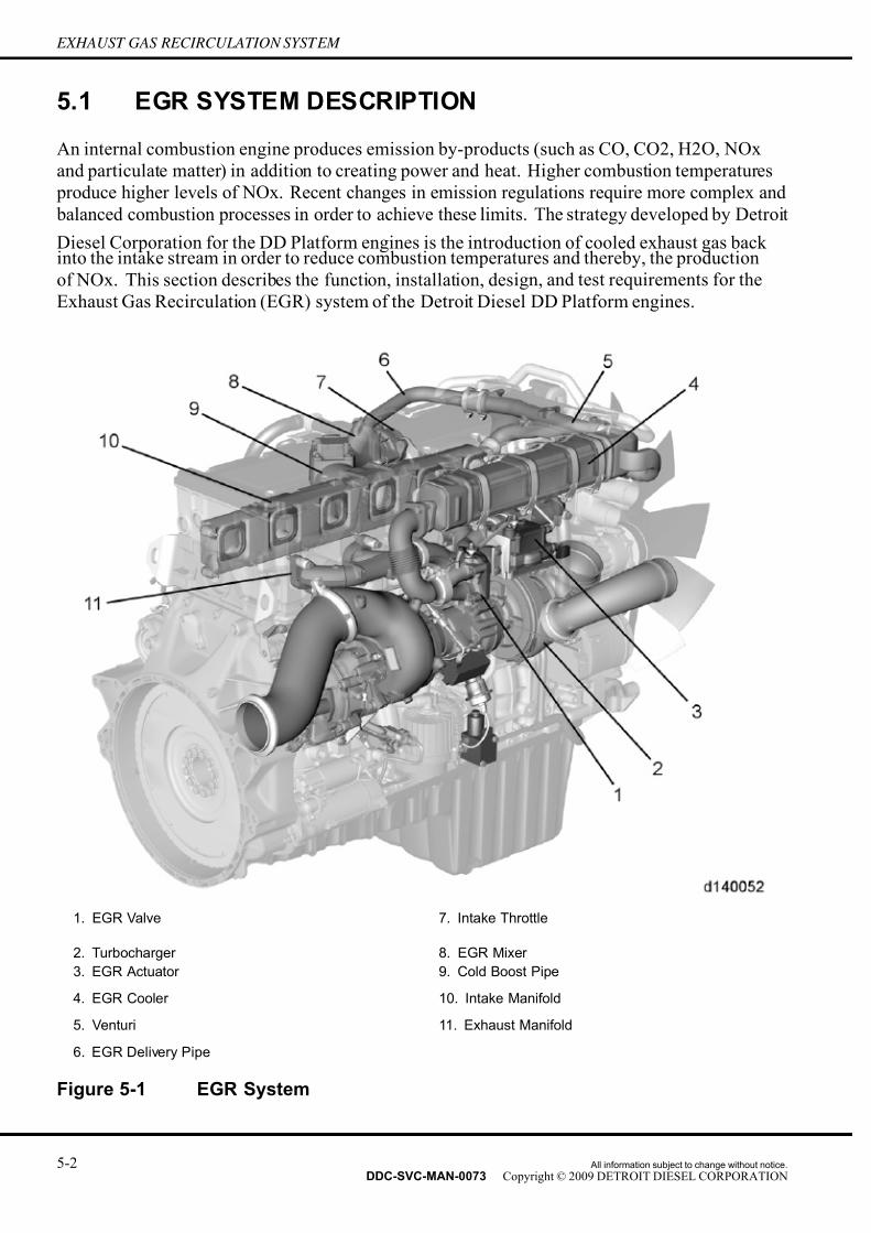
7/14/2019 Dd13-Dd15 a&i Manual
http://slidepdf.com/reader/full/dd13-dd15-ai-manual 70/304
EXHAUST GAS RECIRCULATION SYSTEM
5.1 EGR SYSTEM DESCRIPTION
An internal combustion engine produces emission by-products (such as CO, CO2, H2O, NOx
and particulate matter) in addition to creating power and heat. Higher combustion temperatures
produce higher levels of NOx. Recent changes in emission regulations require more complex and
balanced combustion processes in order to achieve these limits. The strategy developed by Detroit
Diesel Corporation for the DD Platform engines is the introduction of cooled exhaust gas back into the intake stream in order to reduce combustion temperatures and thereby, the production
of NOx. This section describes the function, installation, design, and test requirements for the
Exhaust Gas Recirculation (EGR) system of the Detroit Diesel DD Platform engines.
1. EGR Valve 7. Intake Throttle
2. Turbocharger 8. EGR Mixer
3. EGR Actuator 9. Cold Boost Pipe
4. EGR Cooler 10. Intake Manifold
5. Venturi 11. Exhaust Manifold
6. EGR Delivery Pipe
Figure 5-1 EGR System
5-2 All information subject to change without notice.
DDC-SVC-MAN-0073 Copyright © 2009 DETROIT DIESEL CORPORATION

7/14/2019 Dd13-Dd15 a&i Manual
http://slidepdf.com/reader/full/dd13-dd15-ai-manual 71/304
DD PLATFORM APPLICATION AND INSTALLATION MANUAL
The exhaust gas is routed from the exhaust manifold through a gas to water EGR cooler, through
a venturi, through a modulated mixing valve and into the intake manifold. The mixer valve is
controlled by the engine electronics and are used to control and regulate the flow of EGR. Each
cylinder is filled with a mix of cooled, compressed intake air and recirculated, cooled exhaust
gas. This mix provides for ef ficient combustion with controlled combustion temperatures and a
greatly reduced level of NOx production. The trade-off from the introduction of exhaust gas to
the intake air is an increase in particulate matter. An exhaust Aftertreatment Device (ATD) isused to capture the increased particulate matter.
5.2 INSTALLATION AND DESIGN REQUIREMENTS
The installation of the EGR System is completely controlled by Detroit Diesel Corporation
as part of the manufacturing and production process. There are no unique OEM requirements
relative to the installation of the EGR system.
5.2.1 COOLING SYSTEM
The vehicle radiator must be sized to accommodate the increased heat rejection load resulting
from EGR engines. The radiator must also be designed to handle the increase in water pump
flow volume.
5.2.2 AUXILIARY COOLERS
The coolant supply for auxiliary coolers (i.e. transmission cooler, hydraulic cooler, auxiliary
power unit, etc.) must be plumbed from the coolant collector on the right hand side of the engine.
There are three M27 supply ports at the rear of the coolant collector and two M27 supply ports on
the coolant outlet elbow located at the front of the coolant collector.
5.3 TESTING REQUIREMENTS
There are no unique OEM requirements relative to the testing and verification of the EGR system.
All information subject to change without notice. 5-3DDC-SVC-MAN-0073 Copyright © 2009 DETROIT DIESEL CORPORATION

7/14/2019 Dd13-Dd15 a&i Manual
http://slidepdf.com/reader/full/dd13-dd15-ai-manual 72/304
EXHAUST GAS RECIRCULATION SYSTEM
THIS PAGE INTENTIONALLY LEFT BLANK
5-4 All information subject to change without notice.
DDC-SVC-MAN-0073 Copyright © 2009 DETROIT DIESEL CORPORATION

7/14/2019 Dd13-Dd15 a&i Manual
http://slidepdf.com/reader/full/dd13-dd15-ai-manual 73/304
DD PLATFORM APPLICATION AND INSTALLATION MANUAL
6 EXHAUST SYSTEM
Section Page
6.1 EXHAUST SYSTEM DESCRIPTION ...................................................... 6- 2
6.2 INSTALLATION REQUIREMENTS ......................................................... 6- 5
6.3 DESIGN REQUIREMENTS .................................................................... 6- 8
6.4 TESTING REQUIREMENTS ................................................................... 6- 9
All information subject to change without notice. 6-1DDC-SVC-MAN-0073 Copyright © 2009 DETROIT DIESEL CORPORATION
7/14/2019 Dd13-Dd15 a&i Manual
http://slidepdf.com/reader/full/dd13-dd15-ai-manual 74/304
EXHAUST SYSTEM
6.1 EXHAUST SYSTEM DESCRIPTION
The purpose of the exhaust system is to direct the flow of exhaust gases from the combustion
chamber through the turbocharger and Axial Power Turbine Aftertreatment Device (ATD) and to
an appropriate discharge location.
The exhaust system consists of:
□ Exhaust valves
□ Exhaust manifold
□ Turbocharger
□ Axial Power Turbine
□ Exhaust piping
□ Aftertreatment Device (ATD)
6.1.1 EXHAUST SYSTEM
Exhaust gases exit the cylinders through exhaust ports and the exhaust manifold. At the exhaust
manifold, the exhaust gas is split between the EGR circuit and the exhaust circuit. The flow of
EGR circuit gases is covered in the EGR System Section. The remaining exhaust circuit gases
expand through the exhaust turbine and drive the turbocharger compressor impeller. The exhaust
gases are then routed through the axial power turbine. The axial power turbine converts thermal
energy to mechanical energy through a gear box driving the flywheel. Exhaust gas then flows
through an engine mounted S-pipe through the ATD to an appropriate discharge outlet.
6-2 All information subject to change without notice.
DDC-SVC-MAN-0073 Copyright © 2009 DETROIT DIESEL CORPORATION

7/14/2019 Dd13-Dd15 a&i Manual
http://slidepdf.com/reader/full/dd13-dd15-ai-manual 75/304
DD PLATFORM APPLICATION AND INSTALLATION MANUAL
1. Washer 10. Exhaust Pipe 19. Bolt 28. Clamp
2. Connector 11. Clamp 20. Washer 29. Air Line
3. Banjo Bolt 12. Turbo Outlet Elbow 21. Banjo Bolt 30. Bolt
4. Bracket 13. Gasket 22. Clip 31. Air Seal Pressure
Regulator
5. Bolts 14. Bolts 23. Bolt
6. Turbo Speed Sensor 15. Heat Shield 24. Bracket
7. O-ring 16. Axial Power Turbine 25. Bolt
8. Turbocharger 17. Gear Box 26. Clamp
9. Clamp 18. Bolt 27. Interstage Duct
Figure 6-1 Turbocharger and Related Parts
All information subject to change without notice. 6-3DDC-SVC-MAN-0073 Copyright © 2009 DETROIT DIESEL CORPORATION

7/14/2019 Dd13-Dd15 a&i Manual
http://slidepdf.com/reader/full/dd13-dd15-ai-manual 76/304
EXHAUST SYSTEM
6.1.2 TURBOCHARGER
Compression of air in the turbocharger causes an air mass to flow into the combustion chamber.
The turbocharger consists of a turbine and a compressor which are attached to a shaft. The
exhaust gas flows to the turbine wheel and causes it to turn. This turning motion is transmitted
to the shaft and the compressor impeller. The intake air from the air filter is compressed by the
compressor impeller and flows over a charge air pipe to the charge air cooler. The compressed air is cooled in the charge air cooler; this permits a more dense charge of air to be delivered to the
engine and the output of the engine is increased. The charge air then passes from the charge air
cooler into the charge air manifold cylinders.
The turbocharger is mounted on the exhaust outlet flange of the engine exhaust manifold.
The advantages are as follows:
□ Increases the engine performance and torque
□ Reduction of the fuel consumption compared to a similarly powered naturally aspirated
engine
□ Reduction of emissions
6.1.3 AXIAL POWER TURBINE
The axial power turbine increases the ef ficiency and the economy of the engine by converting
thermal energy, in the exhaust flow from the turbocharger into mechanical energy and delivers the
resulting torque to the crankshaft. The rated speed of the turbine wheel of the axial power turbine
device is about 50,000 rpm. The turbine wheel generates a torque in this range of about 10 N·m
(7 lb·ft) which is increased through var ious gear ratios of gears up to 260 N·m (192 lb·ft). The
exhaust gas flows to the turbine wheel of the axial power turbine device and drives the wheel.
The rotational movement created is transmitted to the shaft the small output gear and from the
small output gear to the large output gear of the hydrodynamic clutch. The rotational speed is
reduced because of the gear ratio between the output gear and drive gear and the torque increased.
The impeller of the hydrodynamic clutch is connected to the housing of the hydrodynamic clutch
to the drive gear and turns at the same rotational speed. The vanes on the impeller generate an
oil flow in the hydrodynamic clutch which sets the turbine wheel of the hydrodynamic clutch
into rotation and the output gear is driven over a shaft. The generated torque is transferred to the
gear for the crankshaft via the intermediate gear and therefore to the crankshaft. It is therefore
also possible to ensure via the hydrodynamic clutch that rotational speed matching takes place
between the crankshaft and the axial power turbine-drive.
The axial power turbine device is connected to the engine oil circuit. The gears and the bearing
are lubricated and cooled by the engine oil. The hydrodynamic clutch is supplied with engineoil by the hollow bearing shaft. One special aspect is the seal between the shaft and the exhaust
turbine housing. The seal between these two components takes place by using two metal sealing
rings which are pressed into their seat by compressed air. The pressure for pressing these sealing
rings is reduced over the axial power turbine air seal pressure regulator valve to 0.5 bar which is
actuated by the Motor Control Module (MCM) as soon as the engine starts.
6-4 All information subject to change without notice.
DDC-SVC-MAN-0073 Copyright © 2009 DETROIT DIESEL CORPORATION

7/14/2019 Dd13-Dd15 a&i Manual
http://slidepdf.com/reader/full/dd13-dd15-ai-manual 77/304
DD PLATFORM APPLICATION AND INSTALLATION MANUAL
6.2 INSTALLATION REQUIREMENTS
The exhaust system must be designed to minimize the resistance to the flow of exhaust gases
(back pressure). The ATD, in addition to acting as an exhaust catalyst and particulate filter also
provides a level of noise attenuation so that a traditional muf fler should no longer be required.
A flexible section of piping is required between the turbocharger turbine outlet and the inlet to
the ATD. This flexible section is necessary to minimize the amount of engine vibration that istransmitted to the exhaust system and the ATD. Additionally, since Detroit Diesel ATDs actively
regenerate the diesel particulate filter (DPF) using diesel fuel, the flexible section must prevent
any and all exhaust leaks.
The exhaust system upstream of the ATD will be operating at pressures higher than what previous
engines had upstream of the muf fler. The exhaust system must be capable of withstanding these
pressures to prevent exhaust leaks. Adequate clearance must be provided for the complete exhaust
system. The exhaust must not be routed too close to engine or vehicle components such that
exhaust heat will The minimum required exhaust pipe Inside Diameter (I.D.) for DD Platform
engines can be found at www.detroitdiesel.com.
These sizes may be used for the initial sizing of the exhaust system. Increase the pipe size or modify the piping configuration if the calculated back pressure exceeds the maximum limit.
6.2.1 BACK PRESSURE
The vehicle exhaust system introduces flow restriction or back pressure to the engine exhaust
system. The design of the vehicle exhaust system should minimize this flow restriction.
Vehicle exhaust systems include pi ping from the engine exhaust outlet to the ATD and exhaust
discharge to the environment. The ATD causes exhaust flow restriction as well, however, vehicle
manufacturers must comply with DD Platform exhaust back pressure specifications published
at www.detroitdiesel.com.
One or more of the following factors usually causes excessive back pressure:
□ Small exhaust pipe diameter
□ Excessive number of sharp bends in the system
□ Long exhaust pipe between the manifold and ATD
□ Reduced power
□ Poor fuel economy
□ High combustion temperature
□ Over-heating
□ Excessive smoke
□ Reduced engine life
All information subject to change without notice. 6-5DDC-SVC-MAN-0073 Copyright © 2009 DETROIT DIESEL CORPORATION

7/14/2019 Dd13-Dd15 a&i Manual
http://slidepdf.com/reader/full/dd13-dd15-ai-manual 78/304
EXHAUST SYSTEM
6.2.2 NOISE
The exhaust system is one of the principal noise sources on many types of applications. Exhaust
noise is caused by the intermittent release of high pressure exhaust gas from the engine cylinders,
causing pulsations in the exhaust pipe. These pulsations lead not only to discharge noise at the
outlet, but also to noise radiation from the exhaust pipe and muf fler shell surfaces. The ATD
provides a level of noise cancellation such that a traditional muf fler should not be required.Double wall piping helps to reduce radiant noise. It remains the responsibility of the OEM to
comply will all applicable noise standards.
6.2.3 FLEXIBLE FITTINGS
A flexible exhaust fitting or joint should separate the engine and exhaust system. Premature failure
of the turbocharger, manifold, piping, ATD or joints caused by engine vibration may be prevented
by including flexible joints or fittings. A flexible joint allows for thermal expansion and facilitates
alignment of the engine with the exhaust system piping. A traditional style flexible section is not
acceptable due to its inherent tendency to leak. Detroit Diesel recommends a bellows style flexible
section in order to provide the necessary vibration isolation while providing a relatively leak-freesection. The bellows section must be able to withstand operating pressures up to 31 kPa (4.5 psi).
NOTE:Never allow the engine manifold or turbocharger to support the weight of the exhaust
system.
6.2.4 EXHAUST CONNECTION POINTS
The axial power turbine outlet utilizes a marmon flange that the vehicle exhaust system must
mount to.
6-6 All information subject to change without notice.
DDC-SVC-MAN-0073 Copyright © 2009 DETROIT DIESEL CORPORATION

7/14/2019 Dd13-Dd15 a&i Manual
http://slidepdf.com/reader/full/dd13-dd15-ai-manual 79/304
DD PLATFORM APPLICATION AND INSTALLATION MANUAL
Figure 6-2 Turbine Outlet Connection Points for DD15™
Figure 6-3 Turbine Outlet Connection Points for DD13™
All information subject to change without notice. 6-7DDC-SVC-MAN-0073 Copyright © 2009 DETROIT DIESEL CORPORATION

7/14/2019 Dd13-Dd15 a&i Manual
http://slidepdf.com/reader/full/dd13-dd15-ai-manual 80/304
EXHAUST SYSTEM
6.2.5 MATERIAL SPECIFICATIONS FOR PIPEWORK
The minimum required exhaust pipe diameter for the DD Platform engines can be found at
www.detroitdiesel.com. Detroit Diesel recommends AL409SS with a minimum wall thickness of
1.2 mm (0.047 in.) for all exhaust piping. The exhaust piping support must be secure, but still
allow for thermal expansion and contraction. Mounting points should be on structurally sound
members, such as the vehicle/vessel frame. Thermal insulation is required for all piping betweenthe turbocharger and the ATD inlet in order to maintain as much exhaust temperature as possible
within the exhaust flow. The temperature of the exhaust gas as it reaches the inlet to the ATD is
critical to both the function of the DOC as well as regeneration of the DPF. Double wall piping is
common in automotive applications. Exposed exhaust system components should not be located
near flammable or otherwise temperature sensitive materials. Insulating the exhaust system will
reduce the heat radiation and noise level caused by the exhaust system.
6.3 DESIGN REQUIREMENTS
The exhaust system for DD Platform powered vehicles must function under a variety of
environmental conditions. Exposure to rain and snow and subjection to both thermal andmechanical stresses are inherent to vehicle operation.
6.3.1 TEMPERATURE DROP FROM TURBOCHARGER OUTLET TOAFTERTREATMENT DEVICE
The temperature of the exhaust gas as it reaches the inlet to the ATD is critical in both the function
of DOC and the regeneration of the DPF (passively and actively). The maximum temperature
drop allowed from the turbo outlet to the ATD inlet is 30°C (54°F) throughout the entire operating
range, including “high idle,” which is defined as the elevated rpm and load where a stationary
regeneration may occur. In order to maintain this temperature drop and retain as much of theexhaust energy as possible, the exhaust piping between the turbo and the ATD will require either
insulation or double wall tubing.
6.3.2 DISTANCE FROM HYDROCARBON DOSER TO ATD INLET
A minimum of 0.8 meters (31 in.) of piping is required between the HC Doser and the inlet to the
ATD. This length of piping is critical for the evaporation of fuel being injected into the exhaust
stream during active regeneration. In the future, this specification may be modified to include
a maximum length between the HC Doser and the ATD inlet.
6.3.3 OUTLET LOCATION
Select the direction and location of the tailpipe exit to prevent the following:
□ Recirculation of exhaust into the air inlet
□ Recirculation of exhaust through the radiator and charge air cooler
□ Recirculation of exhaust into cab
6-8 All information subject to change without notice.
DDC-SVC-MAN-0073 Copyright © 2009 DETROIT DIESEL CORPORATION

7/14/2019 Dd13-Dd15 a&i Manual
http://slidepdf.com/reader/full/dd13-dd15-ai-manual 81/304
DD PLATFORM APPLICATION AND INSTALLATION MANUAL
□ Obstruction of the vehicle operator's line of sight
□ Excessive noise emissions
Active regeneration may result in exhaust outlet temperatures of approximately 650°C (1200°F)
at the ATD outlet. OEM piping beyond the ATD will reduce the exhaust temperature vented to the
atmosphere. When designing exhaust system piping beyond the ATD, consideration should be
given to these temperatures.
6.3.4 DRAINAGE
The exhaust system must be designed to prevent rain water from entering the engine. For vertical
exhaust systems, it is recommended that the exhaust outlet be fitted with a counterbalanced rain
cap. As an alternative, the end of the outlet pipe may be bent rearward 90 degrees, with the
end cut on a diagonal such that the upper half is longer than the lower half. The exhaust pipe
can accumulate a considerable amount of condensed moisture, especially in long piping. A
condensation trap and drain are incorporated into the design of vertical ATD configurations.
Horizontal ATD configurations will incorporate provisions to drain rain water as necessary.
6.3.5 SYSTEM INSULATION
Exposed exhaust system parts should not be near wood or other flammable material. Active
regeneration may result in exhaust outlet temperatures of approximately 650°C (1200°F).
Insulating the exhaust system will reduce the heat radiation and the noise level caused by the
exhaust system. Certain applications may require insulated exhaust systems. Some engine
models/ratings are available from the factory with optional insulated exhaust manifolds and
turbocharger turbine housings. Consult DDC Application Engineering before using any type of
insulation on the exhaust manifold or turbocharger on other models or ratings. Improper use of
insulation may contribute to reduced engine component life. Any exhaust system components
downstream of the turbocharger turbine discharge may be insulated as desired.
6.3.6 BENDING MOMENT CALCULATIONS
The maximum allowable value for bending moment at the rear of the turbocharger can be found
at www.detroitdiesel.com, if you do not have access to www.detroitdiesel.com contact your
Distributor. The maximum allowable value for bending moment at both the inlet to the ATD and
the outlet from the ATD can be found at www.detroitdiesel.com. The ATD is significantly more
massive that a traditional muf fler. Stiff brackets should be considered to minimize the ATD inlet
and outlet moment forces.
6.4 TESTING REQUIREMENTS
A thorough evaluation of the exhaust system will include:
□ Complete descriptions and documentation of the system in the vehicle sign-off form
□ Adequate instrumentation
□ Proper test pre paration
All information subject to change without notice. 6-9DDC-SVC-MAN-0073 Copyright © 2009 DETROIT DIESEL CORPORATION

7/14/2019 Dd13-Dd15 a&i Manual
http://slidepdf.com/reader/full/dd13-dd15-ai-manual 82/304
EXHAUST SYSTEM
□ Accurate tests
□ Data analysis and documentation
□ Diagnostics (troubleshooting) and corrective action (if necessary)
These tests must be run on all new installations, engine repowers, or whenever modifications
have been made to the engine exhaust system. The appropriate section of the vehicle sign-off
form must be completed.
6.4.1 MEASUREMENT OF EXHAUST BACK PRESSURE
The back pressure limit for 2007 and beyond will be measured differently than in the past. The
OEM has no control over the design and performance of the ATD, which would have a significant
impact on back pressure measured in the traditional manner. In addition, depending on the amount
of engine hours accumulated prior to the back pressure check, a considerable amount of particulate
matter and ash may have accumulated in the ATD further increasing the total back pressure.
Figure 6-4 Piezometer Ring
As a result, Detroit Diesel will only hold the OEM accountable for the piping controlled by the
OEM. Back pressure will be measured across the piping between the turbo outlet and the ATDinlet combined with the back pressure measured on the piping downstream of the ATD outlet.
These two values will be combined and restricted to a maximum value of 4.0 kPa (1.2 in. Hg).
6-10 All information subject to change without notice.
DDC-SVC-MAN-0073 Copyright © 2009 DETROIT DIESEL CORPORATION
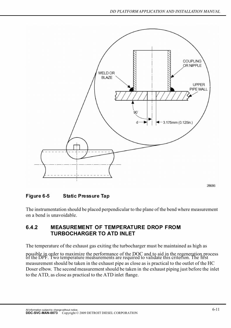
7/14/2019 Dd13-Dd15 a&i Manual
http://slidepdf.com/reader/full/dd13-dd15-ai-manual 83/304
DD PLATFORM APPLICATION AND INSTALLATION MANUAL
Figure 6-5 Static Pressure Tap
The instrumentation should be placed perpendicular to the plane of the bend where measurement
on a bend is unavoidable.
6.4.2 MEASUREMENT OF TEMPERATURE DROP FROMTURBOCHARGER TO ATD INLET
The temperature of the exhaust gas exiting the turbocharger must be maintained as high as
possible in order to maximize the performance of the DOC and to aid in the regeneration processof the DPF. Two temperature measurements are required to validate this criterion. The first
measurement should be taken in the exhaust pipe as close as is practical to the outlet of the HC
Doser elbow. The second measurement should be taken in the exhaust piping just before the inlet
to the ATD, as close as practical to the ATD inlet flange.
All information subject to change without notice. 6-11DDC-SVC-MAN-0073 Copyright © 2009 DETROIT DIESEL CORPORATION

7/14/2019 Dd13-Dd15 a&i Manual
http://slidepdf.com/reader/full/dd13-dd15-ai-manual 84/304
EXHAUST SYSTEM
6.4.3 MEASUREMENT OF EXHAUST LEAKAGE BETWEENTURBOCHARGER AND ATD INLET
In order to maximize the effectiveness of the ATD, exhaust leaks upstream of the ATD must be
kept to a minimum. To accurately measure the exhaust leakage, a bench test is required according
to the following procedure:
1. Seal the ends of the exhaust pipe assembly (everything located between the turbocharger
outlet and the ATD inlet) with Marmon flange caps.
2. Install an air fitting on one cap supplied with regulated air and a shutoff valve.
3. Install a flow meter to record the air leakage rate in the exhaust piping assembly.
4. Pressurize the exhaust piping assembly to 31 kPa (4.5 psi).
5. Measure the leakage rate and compare it to the 10 Standard Liters Per Minute (SLPM) per
joint specification.
6. The system leakage rate between the turbocharger and ATD inlet should not exceed 30
slpm.7. No visible smoke/fuel is allowed during a high idle regeneration.
6-12 All information subject to change without notice.
DDC-SVC-MAN-0073 Copyright © 2009 DETROIT DIESEL CORPORATION
7/14/2019 Dd13-Dd15 a&i Manual
http://slidepdf.com/reader/full/dd13-dd15-ai-manual 85/304
DD PLATFORM APPLICATION AND INSTALLATION MANUAL
7 AFTERTREATMENT SYSTEM
Section Page
7.1 AFTERTREATMENT SYSTEM DESCRIPTION ..................................... 7- 2
7.2 SYSTEM DESCRIPTION / OPERATION ................................................ 7- 4
7.3 AFTERTREATMENT DEVICE DESIGN FEATURES .............................. 7-10
7.4 AFTERTREATMENT DEVICE VARIATIONS .......................................... 7-11
7.5 NOISE ATTENUATION ........................................................................... 7-12
7.6 MASS OF THE AFTERTREATMENT DEVICE ....................................... 7-12
7.7 MOUNTING REQUIREMENTS ............................................................... 7-12
All information subject to change without notice. 7-1DDC-SVC-MAN-0073 Copyright © 2009 DETROIT DIESEL CORPORATION

7/14/2019 Dd13-Dd15 a&i Manual
http://slidepdf.com/reader/full/dd13-dd15-ai-manual 86/304
AFTERTREATMENT SYSTEM
7.1 AFTERTREATMENT SYSTEM DESCRIPTION
Detroit Diesel Corporation continues its efforts to reduce exhaust emissions. Two primary exhaust
gas constituents are Oxides of Nitrogen (NOx) and Particulate Matter (PM). Diesel particulate
emissions are a mixture of both solid and liquid material. NOx emission reduction can be
achieved by lowering combustion temperature. However, this increases particulate emissions.
Therefore, when low NOx levels are achieved, an Aftertreatment Device (ATD) can be used tosimultaneously reduce particulate emissions. Particulate filter technology has been demonstrated
to be very effective in the control of particulate emissions.
The aftertreatment system consists of the following components:
The ATS is comprised of the following components:
Component Description
Aftertreatment Device
An engine exhaust device that contains a DOC and
a DPF along with several pressure and temperature
sensors that work in conjunction to reduce particulate
emissions from the engine.
Intake Throttle Valve
Electronically controlled valve that will open or close in
order to control a proper temperature at the face of the
DOC during regeneration.
Fuel Doser Valve
Coolant cooled valve used to deliver fuel into the exhaust
stream to maintain the proper temperature across the
DOC during regeneration.
Doser Block Assembly
Assembly that houses the Fuel Cutoff Valve (FCV),
Fuel Compensation Pressure (FCP) Sensor, Electronic
Dosing Valve (EDV) and the Fuel Line Pressure (FLP)
Sensor.
Fuel Cutoff ValveControls fuel flow into the Doser Block Assembly, is
either On or Off.
Fuel Line Pressure Sensor Pressure sensor used to diagnose abnormal conditions
in fuel pressure after fuel exits the Doser Block Assembly.
Electronic Dosing Valve
Pulse Width Modulation (PWM) controlled valve used to
deliver the correct amount of fuel to the FDV in order to
maintain the proper temperature across the DOC during
regeneration.
Fuel Compensation Pressure Sensor
Monitors fuel pressure into the Doser Block Assembly
in order to properly deliver the correct amount of fuel
delivered via the Electr onic Dosing Valve.
Table 7-1 ATS Component Descriptions
7-2 All information subject to change without notice.
DDC-SVC-MAN-0073 Copyright © 2009 DETROIT DIESEL CORPORATION

7/14/2019 Dd13-Dd15 a&i Manual
http://slidepdf.com/reader/full/dd13-dd15-ai-manual 87/304
DD PLATFORM APPLICATION AND INSTALLATION MANUAL
1. Aftertreatment Device 5. Fuel Cutoff Valve
2. Intake Throttle Valve 6. Fuel Line Pressure Sensor
3. Fuel Doser Valve 7. Electronic Dosing Valve
4. Doser Block Assembly 8. Fuel Compensation Pressure Sensor
Figure 7-1 Components of Aftertreatment System
A schematic of the DD Platform aftertreatment system is shown in the following illustration.
All information subject to change without notice. 7-3DDC-SVC-MAN-0073 Copyright © 2009 DETROIT DIESEL CORPORATION

7/14/2019 Dd13-Dd15 a&i Manual
http://slidepdf.com/reader/full/dd13-dd15-ai-manual 88/304
AFTERTREATMENT SYSTEM
Figure 7-2 DD Platform Aftertreatment System Schematic
7.2 SYSTEM DESCRIPTION / OPERATION
The Detroit Diesel aftertreatment system is comprised of different sub-systems that work together
to ensure emission compliance on all engines.
7-4 All information subject to change without notice.
DDC-SVC-MAN-0073 Copyright © 2009 DETROIT DIESEL CORPORATION

7/14/2019 Dd13-Dd15 a&i Manual
http://slidepdf.com/reader/full/dd13-dd15-ai-manual 89/304
DD PLATFORM APPLICATION AND INSTALLATION MANUAL
1. Aftertreatment Device Assembly 5. Fuel Cutoff Valve
2. Intake Throttle 6. Fuel Pressure Sensor
3. Fuel Doser Valve 7. Electronic Diesel Dosing Valve
4. HC Doser Block Assembly 8. Fuel Compensation Pressure Sensor
Figure 7-3 Aftertreatment System Components
All information subject to change without notice. 7-5DDC-SVC-MAN-0073 Copyright © 2009 DETROIT DIESEL CORPORATION
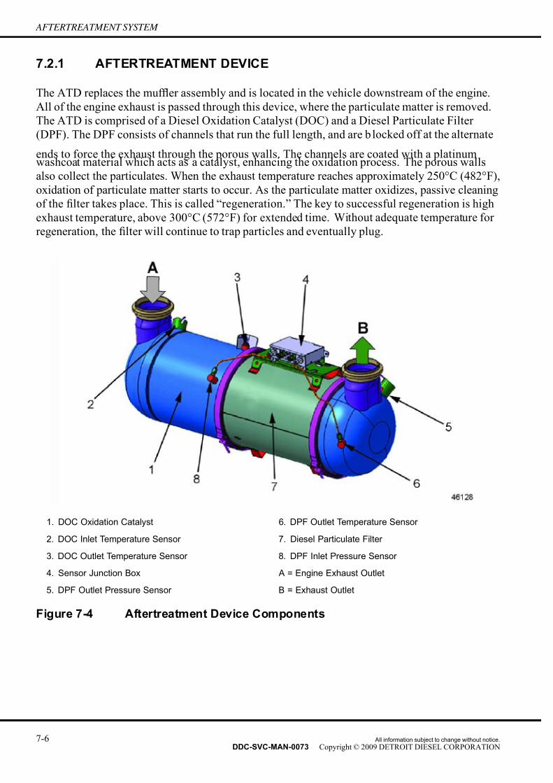
7/14/2019 Dd13-Dd15 a&i Manual
http://slidepdf.com/reader/full/dd13-dd15-ai-manual 90/304
AFTERTREATMENT SYSTEM
7.2.1 AFTERTREATMENT DEVICE
The ATD replaces the muf fler assembly and is located in the vehicle downstream of the engine.
All of the engine exhaust is passed through this device, where the particulate matter is removed.
The ATD is comprised of a Diesel Oxidation Catalyst (DOC) and a Diesel Particulate Filter
(DPF). The DPF consists of channels that run the full length, and are b locked off at the alternate
ends to force the exhaust through the porous walls. The channels are coated with a platinumwashcoat material which acts as a catalyst, enhancing the oxidation process. The porous walls
also collect the particulates. When the exhaust temperature reaches approximately 250°C (482°F),
oxidation of particulate matter starts to occur. As the particulate matter oxidizes, passive cleaning
of the filter takes place. This is called “regeneration.” The key to successful regeneration is high
exhaust temperature, above 300°C (572°F) for extended time. Without adequate temperature for
regeneration, the filter will continue to trap particles and eventually plug.
1. DOC Oxidation Catalyst 6. DPF Outlet Temperature Sensor
2. DOC Inlet Temperature Sensor 7. Diesel Particulate Filter
3. DOC Outlet Temperature Sensor 8. DPF Inlet Pressure Sensor
4. Sensor Junction Box A = Engine Exhaust Outlet
5. DPF Outlet Pressure Sensor B = Exhaust Outlet
Figure 7-4 Aftertreatment Device Components
7-6 All information subject to change without notice.
DDC-SVC-MAN-0073 Copyright © 2009 DETROIT DIESEL CORPORATION

7/14/2019 Dd13-Dd15 a&i Manual
http://slidepdf.com/reader/full/dd13-dd15-ai-manual 91/304
DD PLATFORM APPLICATION AND INSTALLATION MANUAL
Figure 7-5 Operation of the Diesel Particulate Filter
7.2.2 INTAKE THROTTLE
The intake throttle is another sub-system of the ATS that works to thermally manage temperatures
to aid in regeneration of the DPF. This component is electronically controlled by the engine
controller. When the engine controller detects that the filter needs to regenerate that intake throttle
will be commanded to a position that will elevate exhaust temperatures by preventing additional
boost from entering the combustion chambers.
All information subject to change without notice. 7-7DDC-SVC-MAN-0073 Copyright © 2009 DETROIT DIESEL CORPORATION

7/14/2019 Dd13-Dd15 a&i Manual
http://slidepdf.com/reader/full/dd13-dd15-ai-manual 92/304
AFTERTREATMENT SYSTEM
Figure 7-6 Location of the Intake Throttle
7.2.3 HYDROCARBON (HC) DOSER
The HC doser is another sub-system of the ATS that works to actively regenerate the DPF. The
HC doser is comprised of fuel lines, fuel pressure regulator, HC dosing block assembly, and a
mechanical diesel injection valve.
This component is electronically controlled by the engine controller. When the engine controller
detects that the DPF needs to actively regenerate, because soot level is increasing in the DPF,the doser will begin to dose diesel fuel into the exhaust stream and actively regenerate the DPF,
oxidizing the soot off of the DPF to review exhaust system requirements.
7-8 All information subject to change without notice.
DDC-SVC-MAN-0073 Copyright © 2009 DETROIT DIESEL CORPORATION

7/14/2019 Dd13-Dd15 a&i Manual
http://slidepdf.com/reader/full/dd13-dd15-ai-manual 93/304
DD PLATFORM APPLICATION AND INSTALLATION MANUAL
Figure 7-7 Hydrocarbon (HC) Doser Location
Figure 7-8 Hydrocarbon (HC) Doser Location
All information subject to change without notice. 7-9DDC-SVC-MAN-0073 Copyright © 2009 DETROIT DIESEL CORPORATION

7/14/2019 Dd13-Dd15 a&i Manual
http://slidepdf.com/reader/full/dd13-dd15-ai-manual 94/304
AFTERTREATMENT SYSTEM
7.3 AFTERTREATMENT DEVICE DESIGN FEATURES
There are several features, that are designed into the ATD to ease installation and removal of the
ATD into chassis at the production level as well as at the service level. Please refer to the specific
ATD drawing to get dimensions of all these features and where they are located on each ATD.
Figure 7-9 Typical Mounting Views of an Aftertreatment Device
7.3.1 FEET / HOOKS
The feet / hooks are designed to serve as the lifting points for the ATD assembly as well as the
DPF when separated from the ATD assembly. When the DPF is separated from the assembly
the feet / hooks also prevent the weight of the DPF from being supported by the flanges. Failing
to set the DPF on the feet could result in damage to the flanges. They also prevent the ATD
assembly and DPF, when separated, from rolling.
7.3.2 LOCATING DEVICE
The dowel pin is a locating feature that will allow the ATD to be installed rotationally correct. It is
not a mandatory that OEM’s mounting devices (i.e. brackets, straps, etc.) be designed to accept thedowel however it is suggested. Installing the ATD rotationally incorrect will cause stress on inlets
and outlets of the ATD as well as the exhaust plumbing and brackets supporting it. The dowel is
not designed to support any load. Utilizing this locating device can prevent the need for secondary
operations in a manufacturing environment when aligning exhaust plumbing with the ATD.
7-10 All information subject to change without notice.
DDC-SVC-MAN-0073 Copyright © 2009 DETROIT DIESEL CORPORATION

7/14/2019 Dd13-Dd15 a&i Manual
http://slidepdf.com/reader/full/dd13-dd15-ai-manual 95/304
DD PLATFORM APPLICATION AND INSTALLATION MANUAL
7.3.3 SENSOR BOX DISCUSSION
Sensor protection is designed into the ATD as to prevent damaging of the temperature and
pressure sensors. The sensor protection is designed to aid in the prevention of damaging
the sensors when installing the ATD in a manufacturing environment as well as while being
installed during normal operation. Sensor protection should be considered when choosing the
correct variation of ATD as well as location of where it is to be mounted in the application. Thesensor protection should lead the sensors as to prevent debris coming in direct contact with the
sensors. When mounting the ATD in locations near or behind tires, additional shielding should be
considered as to prevent damaging of the sensors.
7.3.4 V-BAND CLAMPS
V-band clamps are designed to simplify the removal and installation of the DPF, a serviceable
component. The DPF collects soot and ash. The soot is burned off either actively or passively.
The ash is stored in the filter and needs regular maintenance to be cleaned out. The “sectioned”
design of the ATD will allow for easy removal of just the serviceable portion of the ATD assembly.
7.3.5 SENSOR AND HARNESS
Sensor orientation should be considered when choosing the correct variation of ATD. Sensor
orientations can be obtained from the ATD drawings. The ATD needs to be mounted such that
the pressure sensor tubing continuously slopes downward away from the pressure sensors as to
prevent condensate from collecting and puddling in the sensors and tubing. This downward
slope is already designed into the pressure sensor tubing on vertical ATDs. The ATD comes as a
complete assembly with the sensors and DPF harness installed. The OEM is responsible for the
jumper harness between the DPF harness and the engine controller harness. The harness should
be shielded or protected as to prevent debris from coming up and damaging the harness andsensors. It should also be mounted to prevent water collection, enabling freezing in cold weather,
causing the wires to potentially break or support the weight of ice chunks. Consideration should
also be given to the serviceability of the DPF portion of the ATD.
7.4 AFTERTREATMENT DEVICE VARIATIONS
There are several different ATDs to accommodate the variations of different engine horsepower
ranges and exhaust routings. There are ATDs that are made for mounting vertically and also
horizontally. Please see the drawing portion of the ATD or call your application engineer to
help find the best ATD for your application.
All information subject to change without notice. 7-11DDC-SVC-MAN-0073 Copyright © 2009 DETROIT DIESEL CORPORATION

7/14/2019 Dd13-Dd15 a&i Manual
http://slidepdf.com/reader/full/dd13-dd15-ai-manual 96/304
AFTERTREATMENT SYSTEM
Figure 7-10 Aftertreatment Device Orientation Variations
7.5 NOISE ATTENUATION
The ATD, in addition to acting as an exhaust catalyst and particulate filter, also provides an
adequate level of noise cancellation so that a traditional muf fler is not required.
7.6 MASS OF THE AFTERTREATMENT DEVICE
The mass of the ATD depends on the configuration of the ATD. The heavy-duty ATDs are in the
range of 130 lbs. (59 kg). The medium-duty ATDs are in the range of 90 lbs. (41 kg). Please refer
to the ATD drawing to get the actual mass of the device you are installing.
7.7 MOUNTING REQUIREMENTS
The ATD is significantly more massive than a traditional muf fler and therefore traditional brackets
and straps that were used to hold traditional muf flers may not suf fice. Please refer to the specific
ATD drawing being installed to get the mounting related data such as mass, mounting zone
dimensions, tor que specifications, bending moments on inlets and outlets, etc. for the specific
ATD being installed. It is important to read the Exhaust System portion of the ATD as theserequirements intertwine with ATD installation requirements.
7-12 All information subject to change without notice.
DDC-SVC-MAN-0073 Copyright © 2009 DETROIT DIESEL CORPORATION

7/14/2019 Dd13-Dd15 a&i Manual
http://slidepdf.com/reader/full/dd13-dd15-ai-manual 97/304
DD PLATFORM APPLICATION AND INSTALLATION MANUAL
7.7.1 MOUNTING ZONES
There are designated areas, or mounting zones, on the ATD that are reinforced. The mounting
zone areas are the only locations where the ATD can be held. If the ATD is held outside the
mounting zones the outer skin of the ATD could indent the outer skin of the ATD potentially
causing a hole. Please refer to the ATD drawing to get the dimensions of the mounting zones
and torque specifications for the specific ATD being installed.
7.7.2 BENDING MOMENT FOR INLETS AND OUTLETS
Under no circumstances should the inlets and outlets of the ATD support the weight exhaust
plumbing going into and out of the ATD. The exception to this rule is for vertical ATDs only. The
outlet is designed to withstand up to a particular amount of unsupported topstack mass. Please
refer to the ATD drawing to get the inlet and outlet bending moment restrictions for the specific
ATD being installed. Anything expected to exceed these limitations needs to have additional
brackets to support the topstack. To reduce the loads into the inlet and outlet of the ATD, stiff
brackets are to be used to mount the ATD to reduce low frequency wave vibration. Suggested
frequency? A flexible section of piping is required between the turbocharger turbine outlet andthe inlet to the ATD. A flexible section is also required on the outlet side of the ATD. These flex
sections are necessary in order to minimize the amount of engine and exhaust system vibration
that is transmitted to the exhaust system and the ATD. Premature failure of the turbocharger,
manifold, piping, ATD or joints caused by engine vibration may be prevented by including
flexible joints or fittings. A flexible joint allows for thermal expansion and facilitates alignment
of the engine with the exhaust system piping. Please refer to the Exhaust System portion of the
ATD. Note that a minimum separation distance of 6mm is needed to pull the DPF portion of
the ATD out of the ATD assembly.
Aftertreatment Components group is going to perform the “lower over pass” crash test to see what
happens with the rain trap and what fails. The DPF portion should not be damaged or else thiswill be an expensive failure.
7.7.3 DRAINAGE
Vertical ATDs have a rain trap incorporated into the top to aid in the prevention of water from
entering the exhaust system. This is not 100% ef ficient. Horizontal ATDs have a small drain hole
on the outlet of the ATD to aid in the prevention of water entering the exhaust system. Exhaust
systems must be designed accordingly to prevent water from entering them and getting back to
the engine. Please refer to the exhaust system portion of the ATD. These designs are secondary
measures for water prevention. Should water pass through the exhaust system into the engine,
catastrophic engine failure can occur. Horizontal ATDs need to be oriented such that the drainhole is in the correct orientation when mounted as to aid in water drainage.
There may be some sort of trap volume that needs to be required.
V = 1.7gal for 4 in.
V = 2.67gal for 5 in.
All information subject to change without notice. 7-13DDC-SVC-MAN-0073 Copyright © 2009 DETROIT DIESEL CORPORATION

7/14/2019 Dd13-Dd15 a&i Manual
http://slidepdf.com/reader/full/dd13-dd15-ai-manual 98/304
AFTERTREATMENT SYSTEM
THIS PAGE INTENTIONALLY LEFT BLANK
7-14 All information subject to change without notice.
DDC-SVC-MAN-0073 Copyright © 2009 DETROIT DIESEL CORPORATION

7/14/2019 Dd13-Dd15 a&i Manual
http://slidepdf.com/reader/full/dd13-dd15-ai-manual 99/304
DD PLATFORM APPLICATION AND INSTALLATION MANUAL
8 COOLING SYSTEM, AIR-TO-AIR CHARGECOOLING
Section Page
8.1 COOLING SYSTEM, AIR-TO-AIR CHARGE COOLING SYSTEM
DESCRIPTION ........................................................................................ 8- 2
8.2 JACKET WATER COOLING SYSTEM ................................................... 8- 2
8.3 THERMOSTAT ........................................................................................ 8- 4
8.4 WATER PUMP ........................................................................................ 8- 7
8.5 TYPES OF COOLING SYSTEMS ........................................................... 8- 8
8.6 AIR-TO-AIR CHARGE COOLING ........................................................... 8-10
8.7 COOLING SYSTEM PERFORMANCE REQUIREMENTS ..................... 8-13
8.8 CHARGE AIR COOLING REQUIREMENTS .......................................... 8-17
8.9 VEHICLE SIGN-OFF ............................................................................... 8-188.10 COOLING SYSTEM DESIGN CONSIDERATIONS ................................ 8-18
8.11 CHARGE AIR COOLING DESIGN GUIDELINES ................................... 8-25
8.12 HEAT EXCHANGER SELECTION .......................................................... 8-27
8.13 FAN SYSTEM RECOMMENDATIONS AND FAN SELECTION ............. 8-28
8.14 RADIATOR COMPONENT DESIGN ....................................................... 8-36
8.15 COOLING SYSTEM EVALUATION TESTS ............................................ 8-55
8.16 COOLING SYSTEM DIAGNOSTICS AND TROUBLESHOOTING GUIDE
.................................................................................................................. 8-76
8.17 MAINTENANCE ...................................................................................... 8-83
All information subject to change without notice. 8-1DDC-SVC-MAN-0073 Copyright © 2009 DETROIT DIESEL CORPORATION

7/14/2019 Dd13-Dd15 a&i Manual
http://slidepdf.com/reader/full/dd13-dd15-ai-manual 100/304
COOLING SYSTEM, AIR-TO-AIR CHARGE COOLING
8.1 COOLING SYSTEM, AIR-TO-AIR CHARGE COOLINGSYSTEM DESCRIPTION
This chapter covers the DD Platform engines air-to-air charge cooling system. The cooling system
for the DD Platform engines is comprised of two separate systems; the jacket water cooling
system and the Charge Air Cooling (CAC) system. Although these systems are separate, they
usually share the same space which makes each system's performance dependent upon the other.
A well designed cooling system is a requirement for satisfactory engine performance and
reliability. Thorough knowledge of the application, duty cycle, and environmental conditions is
essential in designing and packaging the total cooling system. A properly designed system should
still be able to perform within specifications after normal system degradation occurs.
The jacket water cooling system consists of a heat-exchanger or radiator, centrifugal type water
pump, oil cooler, EGR cooler, thermostat, coolant collector and cooling fan. The water pump is
used to pressurize and circulate the engine coolant. The engine coolant is drawn from the lower
portion of the radiator and is forced through the oil cooler and into the cylinder block. The heat
generated by the engine is transferred from the cylinders and oil to the coolant. The heat in the
coolant is then transferred to the air flow generated by the cooling fan when it enters the radiator.
A single full blocking-type thermostat is built in to the thermostat housing on the inlet side of
the water pump. The thermostat is designed to control the flow of coolant, providing fast engine
warm-up and regulate coolant temperature.
The CAC system consists of the air inlet piping, the turbocharger, the cooling fan and the intake
manifold. Ambient air is drawn in through the air cleaner and piping to the exhaust driven
turbocharger. The turbo compresses the air which increases its temperature. The charge air is then
cooled by the air from the cooling fan as it passes through the CAC to the intake manifold.
8.2 JACKET WATER COOLING SYSTEM
When the engine is at normal operating temperature, the coolant passes from the radiator, through
the thermostat housing into the water pump, through the oil cooler, into the cylinder block, up
through the cylinder head, out to the coolant collector, through the EGR cooler and then back
to the radiator. The coolant then passes through a series of tubes where the coolant temperature
is lowered by the air flow created by the fan.
Upon starting a cold engine or when the coolant is below operating temperature, the closed
thermostat prevents coolant flow from the radiator from entering the water pump. Coolant is
recirculated through the engine to aid engine warm-up. When the thermostat opening temperature
is reached, coolant flow is divided between the radiator outlet and the bypass circuit. When the
thermostat is completely open, all of the coolant flow is from the radiator outlet.The function of the engine coolant is to absorb the heat developed as a result of the combustion
process in the cylinders and from component parts such as the valves and pistons which are
surrounded by water jackets. In addition, the heat absorbed by the oil is also removed by the
engine coolant in the oil-to-water oil cooler.
8-2 All information subject to change without notice.
DDC-SVC-MAN-0073 Copyright © 2009 DETROIT DIESEL CORPORATION

7/14/2019 Dd13-Dd15 a&i Manual
http://slidepdf.com/reader/full/dd13-dd15-ai-manual 101/304
DD PLATFORM APPLICATION AND INSTALLATION MANUAL
A pressurized cooling system permits higher temperature operation than a non-pressurized
system. It is essential that the cooling system is kept clean and leak-free, that the filler cap and
pressure relief mechanisms are properly installed and operate correctly, and that the coolant
level is properly maintained.
The following illustrations show the coolant flow within the cooling system.
Figure 8-1 Engine Jacket Water Cooling System — Thermostats Closed
Figure 8-2 Engine Jacket Water Cooling System — Thermostats Fully Open
All information subject to change without notice. 8-3DDC-SVC-MAN-0073 Copyright © 2009 DETROIT DIESEL CORPORATION

7/14/2019 Dd13-Dd15 a&i Manual
http://slidepdf.com/reader/full/dd13-dd15-ai-manual 102/304
COOLING SYSTEM, AIR-TO-AIR CHARGE COOLING
8.3 THERMOSTAT
The temperature of the engine coolant is controlled by a single integral full blocking-type
thermostat located in a housing attached to the left side of the oil / coolant module.
1. Coolant Return — Expansion Tank 2. Coolant Return — Cab Heater
3. Water Pump 4. Thermostat Housing
Figure 8-3 Thermostat and Related Parts
At coolant temperatures below the operating range the thermostat valve remains closed and blocks
the flow of coolant from the radiator to the engine.
During this period, all of the coolant in the system is recirculated through the engine and is
directed back to the suction side of the water pump via a bypass circuit. As the coolant temperature
rises above the start–to–open temperature, the thermostat valve begins to open, restricting the
bypass system, and allowing a portion of the coolant to circulate through the radiator. When the
coolant temperature reaches an approximate fully open temperature, the thermostat valve is fully
open, the bypass system is blocked off, and the coolant is directed through the radiator.
8-4 All information subject to change without notice.
DDC-SVC-MAN-0073 Copyright © 2009 DETROIT DIESEL CORPORATION

7/14/2019 Dd13-Dd15 a&i Manual
http://slidepdf.com/reader/full/dd13-dd15-ai-manual 103/304
DD PLATFORM APPLICATION AND INSTALLATION MANUAL
1. Coolant to EGR Cooler 3. Coolant Inlet from Radiator
2. Coolant Pump 4. Thermostat Housing
Figure 8-4 Cooling System Operation
All information subject to change without notice. 8-5DDC-SVC-MAN-0073 Copyright © 2009 DETROIT DIESEL CORPORATION

7/14/2019 Dd13-Dd15 a&i Manual
http://slidepdf.com/reader/full/dd13-dd15-ai-manual 104/304
COOLING SYSTEM, AIR-TO-AIR CHARGE COOLING
1. EGR Cooler 3. Coolant Outlet to Radiator
2. Coolant Collector
Figure 8-5 Cooling System Operation
A properly operating thermostat is essential for ef ficient operation of the engine.
8.3.1 VENTING
The EGR cooler on the right hand side of the engine has a vent location in the top of the cooler
near the front. This is intended to be used to connect a vent line to the radiator top tank. This vent
line (0.25 in. [6.0 mm] I.D.) should go to the top of the radiator top tank because this point in the
cooling system will be pressurized at all times.
8-6 All information subject to change without notice.
DDC-SVC-MAN-0073 Copyright © 2009 DETROIT DIESEL CORPORATION

7/14/2019 Dd13-Dd15 a&i Manual
http://slidepdf.com/reader/full/dd13-dd15-ai-manual 105/304
DD PLATFORM APPLICATION AND INSTALLATION MANUAL
1. Vent
Figure 8-6 Vent Location
8.4 WATER PUMP
The centrifugal-type water pump circulates the engine coolant through the coolant system.
The pump is mounted on the left side of the engine in the oil / coolant module and is belt driven.
All information subject to change without notice. 8-7DDC-SVC-MAN-0073 Copyright © 2009 DETROIT DIESEL CORPORATION

7/14/2019 Dd13-Dd15 a&i Manual
http://slidepdf.com/reader/full/dd13-dd15-ai-manual 106/304
COOLING SYSTEM, AIR-TO-AIR CHARGE COOLING
1. Coolant Pump Pulley 4. Coolant Filter
2. Coolant Pump 5. Thermostat Housing Gasket
3.Coolant Pump Gasket 6. Thermostat Housing
Figure 8-7 Water Pump Mounting
8.5 TYPES OF COOLING SYSTEMS
Radiator cooling systems can be classified into two broad categories: rapid warm-up and
conventional.
8.5.1 RAPID WARM-UP COOLING SYSTEM RECOMMENDED DESIGN
The rapid warm-up cooling system eliminates coolant flow through the radiator core during
closed thermostat operation.
This reduces war m-up time and maintains coolant temperature near the thermostat start to open
value. Having the deaeration tank (internal or remote) separated from the radiator core will
accomplish this. External bleed and fill lines as well as internal standpipe(s) (radiator core air
vent) are required in the deaeration tank. Proper size and location of these components are critical
to having a balanced system. The fill line coolant return flow capabilities must exceed the flow
into the tank under all operating modes. The rapid warm-up cooling system has also been called
positemp, continuous deaeration, or improved deaeration.
8-8 All information subject to change without notice.
DDC-SVC-MAN-0073 Copyright © 2009 DETROIT DIESEL CORPORATION

7/14/2019 Dd13-Dd15 a&i Manual
http://slidepdf.com/reader/full/dd13-dd15-ai-manual 107/304
DD PLATFORM APPLICATION AND INSTALLATION MANUAL
Another advantage of this system is its ability to place a positive head on the water pump, thus
reducing the possibility of cavitation.
Figure 8-8 Rapid Warm-up Cooling System — Remote Tank, Cross Flow andDown Flow Radiators
All information subject to change without notice. 8-9DDC-SVC-MAN-0073 Copyright © 2009 DETROIT DIESEL CORPORATION

7/14/2019 Dd13-Dd15 a&i Manual
http://slidepdf.com/reader/full/dd13-dd15-ai-manual 108/304
COOLING SYSTEM, AIR-TO-AIR CHARGE COOLING
8.5.2 AUXILIARY AIR-COOLED COOLER CORES
Heat exchangers in addition to jacket water and charge air cooler radiators are quit e often part
of the total cooling system. Heat exchangers such as air-to-oil, air-to-air, oil-to-air, or others
are to be used and mounted either in front of the radiator or behind it. Consider the following
factors if auxiliary coolers are used:
□ Greater restriction of air flow
□ Increased heat load
NOTE:Provide access to the areas between the cores for cleaning purposes.
8.5.3 COOLANT HEATERS
Cold weather operation often requires the use of coolant heaters. Information on coolant heaters
can be obtained from DDC Application Engineering.
8.6 AIR-TO-AIR CHARGE COOLING
An air-to-air charge air cooler is mounted ahead of or beside the engine coolant radiator. The
pressurized intake charge is routed from the discharge side of the turbocharger, through the CAC,
and then to the intake manifold. This effectively reduces the temperature of the compressed air
leaving the turbocharger, permitting a denser charge of air to be delivered to the engine. Cooling
is accomplished by outside air directed past the cooling fins and core tubes of the CAC.
Figure 8-9 Typical Charge Air Cooling System Right Side
8-10 All information subject to change without notice.
DDC-SVC-MAN-0073 Copyright © 2009 DETROIT DIESEL CORPORATION

7/14/2019 Dd13-Dd15 a&i Manual
http://slidepdf.com/reader/full/dd13-dd15-ai-manual 109/304
DD PLATFORM APPLICATION AND INSTALLATION MANUAL
Figure 8-10 Typical Charge Air Cooling System Left Side
The intake air charge is routed to the cylinders by an intake manifold which directs the air to
ports in the cylinder head, through two intake valves per cylinder, and into the cylinder. At the
beginning of the compression stroke, each cylinder is filled with clean, fresh air which provides
for ef ficient combustion.
Figure 8-11 Air-to-Air Charge Air Cooler System
All information subject to change without notice. 8-11DDC-SVC-MAN-0073 Copyright © 2009 DETROIT DIESEL CORPORATION

7/14/2019 Dd13-Dd15 a&i Manual
http://slidepdf.com/reader/full/dd13-dd15-ai-manual 110/304
COOLING SYSTEM, AIR-TO-AIR CHARGE COOLING
8.6.1 CHARGE AIR COOLER
A CAC is normally mounted ahead of the cooling system radiator. The compressed air leaving
the turbocharger is directed through the charge air cooler before it goes to the air inlet side of the
intake manifold. A typical arrangement with a CAC placed in front of the radiator with a suction
fan. With a blower fan, the CAC would be between the radiator and the engine.
Figure 8-12 Typical Charge Air Cooler
The CAC is used to reduce the compressed air temperature leaving the turbocharger before it
reaches the intake manifold. This permits a more dense charge of air to be delivered to the engine.
Figure 8-13 Charge Air Cooler Cross-Section
8-12 All information subject to change without notice.
DDC-SVC-MAN-0073 Copyright © 2009 DETROIT DIESEL CORPORATION

7/14/2019 Dd13-Dd15 a&i Manual
http://slidepdf.com/reader/full/dd13-dd15-ai-manual 111/304
DD PLATFORM APPLICATION AND INSTALLATION MANUAL
Cooling is accomplished by incoming air flowing past the tubes and fins of the intercooler. The
compressed intake charge flowing inside the CAC core transfers the heat to the tubes and fins
where it is picked up by the incoming outside air. Powder coated, painted, untreated mild steel
is unacceptable for piping.
Aluminum, aluminized steel, stainless steel or fi ber reinforced plastic piping is used to transfer the
air from the turbocharger outlet to the CAC, and from there to the intake manifold.
Flexible rubber couplings and hose clamps are used to secure the duct work to the turbocharger,
the CAC inlet and outlet, and the intake manifold.
8.7 COOLING SYSTEM PERFORMANCE REQUIREMENTS
Engine heat transferred to the coolant must be dissipated at a suf ficient rate so engine coolant
temperature does not exceed established safe limits under all operating conditions. The
typical maximum engine coolant temperature is 237°F. Specific requirements may be found
on www.detroitdiesel.com, if you do not have access to www.detroitdiesel.com contact your
Distributor
The maximum ambient temperature at which the maximum engine coolant temperature is reached
is referred to as ambient capability.
Operating with antifreeze, at high elevation, or other severe environmental conditions will
require increasing the cooling capability of the system so the maximum allowable engine coolant
temperature is not exceeded.
8.7.1 SYSTEM FILL
The cooling system must have suf ficient venting (air bleeding) to permit filling at a minimum
continuous rate of 3 gal/min. (4.5 L/min) and on an interrupted basis using a 2-3 gallon (10 liter)
bucket. The amount of coolant needed to complete the fill must not exceed the satisfactorydrawdown amount upon first indication of a full system. This is also a requirement for interrupted
fill.
8.7.2 SYSTEM DRAIN
Suf ficient drains, strategically located, must be provided so the cooling system can be drained to:
□ Prevent freeze problems during cold weather storage
□ Remove all contaminated coolant during system cleaning
□ Minimize refill problems due to trapped air or water pockets
8.7.3 DEAERATION
The cooling system must be capable of expelling all entrapped air within 30 minutes while running
the engine near rated speed after an initial fill. The water pump must not become air bound.
All information subject to change without notice. 8-13DDC-SVC-MAN-0073 Copyright © 2009 DETROIT DIESEL CORPORATION

7/14/2019 Dd13-Dd15 a&i Manual
http://slidepdf.com/reader/full/dd13-dd15-ai-manual 112/304
COOLING SYSTEM, AIR-TO-AIR CHARGE COOLING
NOTICE:
An air bound pump cannot adequately circulate coolant. This canlead to overheating and severe engine damage.
8.7.4 SYSTEM COOLANT CAPACITY
Total cooling system coolant capacity must be known in order to determine the expansion and
deaeration volumes required in the top tank.
8-14 All information subject to change without notice.
DDC-SVC-MAN-0073 Copyright © 2009 DETROIT DIESEL CORPORATION

7/14/2019 Dd13-Dd15 a&i Manual
http://slidepdf.com/reader/full/dd13-dd15-ai-manual 113/304
DD PLATFORM APPLICATION AND INSTALLATION MANUAL
Figure 8-14 Percent Increases in Volume for Water and Antifreeze Solution
The total capacity must include the basic engine, radiator, heater circuit, plumbing, etc. A
minimum 6% expansion volume must be provided in the top tank along with a 2% deaeration
volume and suf ficient reserve volume to meet drawdown capacity. This volume must be provided,
with or without a coolant recovery system.
All information subject to change without notice. 8-15DDC-SVC-MAN-0073 Copyright © 2009 DETROIT DIESEL CORPORATION

7/14/2019 Dd13-Dd15 a&i Manual
http://slidepdf.com/reader/full/dd13-dd15-ai-manual 114/304
COOLING SYSTEM, AIR-TO-AIR CHARGE COOLING
Basic engine coolant capacity is found on www.detroitdiesel.com, if you do not have access to
www.detroitdiesel.com contact your Distributor.
8.7.5 DRAWDOWN CAPACITY
Drawdown capacity is the amount of coolant which can be removed from the system before the
coolant pump begins to cavitate. The drawdown capacity for DD Platform engines is 10% of the total cooling capacity. System design must permit reasonable loss of coolant from the hot
full level before aeration of the coolant begins. Additional coolant capacity may be necessary if
aeration begins before this point. Perform drawdown tests at the maximum tilt angle.
8.7.6 CORE CONSTRUCTION
Tube and plate fin design is preferred because of lower restriction to both air and coolant flow.
Tube and plate fin designs are easier to clean than louvered serpentine types and generally of more
rugged construction making it more suitable to operate in the diesel engine environment.
8.7.7 WATER PUMP INLET PRESSURE/MAXIMUM STATIC HEAD
When the engine is operating at maximum rated engine speed, fill cap removed, and thermostat
fully opened, the water pump inlet pressure must not be lower than atmospheric pressure (suction)
with a rapid warm-up cooling system
These requirements must be met to minimize water pump cavitation and corresponding loss in
coolant flow. Keep restrictions to the water pump inlet such as radiator cores, heat exchanger,
auxiliary coolers and the associated plumbing to a minimum.
The maximum static head allowed on DD Platform engines is 145 kPa (21 psi). and the pressure
relief valve or cap must be sized so the limit is not exceeded. Consider a non-pressurized ventedcap system for radiators mounted 312 m (5 ft.) and higher above the engine. This ensures that
the limit is not exceeded.
8.7.8 COOLANT FLOW RATE/EXTERNAL PRESSURE DROP
The coolant flow rate through the engine and radiator must be within 90% of the rated flow .found
on www.detroitdiesel.com, if you do not have access to www.detroitdiesel.com contact your
Distributor. Ensure that the flow is maintained when coolant is shunted away from the engine or
radiator to supply cab heaters, air compressors, auxiliary coolers, wet exhaust systems, etc.
External pressure drop is defined as the sum of all components in the system. For example, a
radiator with a 21 kPa (3 psi) restriction plus a heat exchanger, with a 14 kPa (2 psi) restriction
mounted between the water pump and oil cooler gives a total pressure drop of 34 kPa (5 psi). This
is within the typical DD Platform engine maximum allowable value. See www.detroitdiesel.com
for current data.
8-16 All information subject to change without notice.
DDC-SVC-MAN-0073 Copyright © 2009 DETROIT DIESEL CORPORATION

7/14/2019 Dd13-Dd15 a&i Manual
http://slidepdf.com/reader/full/dd13-dd15-ai-manual 115/304
DD PLATFORM APPLICATION AND INSTALLATION MANUAL
8.7.9 MINIMUM COOLANT TEMPERATURE
The overall design should ensure minimum coolant temperature 71°C (160°F) be maintained
under all ambient operating conditions; operating conditions are listed on www.detroitdiesel.com..
A cold running engine can result in poor engine performance, excessive white smoke, and
reduced engine life.
8.7.10 SYSTEM PRESSURIZATION
DD Platform engines typically require a minimum 62 kPa (9 psi) pressure cap. See
www.detroitdiesel.com for specific requirements. The pressure caps raise the boiling point of
the coolant which minimizes coolant or flow rate loss due to localized boiling and water pump
cavitation. Higher rated pressure caps may be required for high altitude and severe ambient
operation. Cooling system components must be able to withstand increased pressure.
8.7.11 COOLANTS
A proper glycol (ethylene, propylene) or extended life organic acid, water, Supplemental Coolant
Additive (SCA) mixture meeting DDC requirements is required for year-round usage.
The coolant provides freeze and boil protection and reduces corrosion, sludge formation, and
cavitation erosion. Antifreeze concentration should not exceed 67% for ethylene glycol (50%
for propylene glycol). Detroit Diesel requires SCAs be added to all cooling systems at initial fill
and be maintained at the proper concentration. Follow SCA manufacturers' recommendations.
Refer to Coolant Selections for Engine Cooling Systems (DDC-SVC-BRO-0002), available
on www.detroitdiesel.com.
8.8 CHARGE AIR COOLING REQUIREMENTS
Suf ficient cooling capability is required for optimum engine performance. Exceeding the system
temperature and pressure design limits defined in this chapter can adversely affect fuel economy,
power, emissions and durability.
8.8.1 COOLING CAPABILITY
The cooling capability of the air-to-air system must be suf ficient to reduce the turbocharger
compressor out air temperature to within 25°C (45°F) of ambient temperature on all DD Platform
engines. Air inlet manifold temperature requirements are available on www.detroitdiesel.com.
Typically the maximum intake manifold temperature is 85°C (185°F).
8.8.2 MAXIMUM PRESSURE LOSS
The maximum allowable total static pressure drop across the DD Platform charge air system is
13.5 kPa (4 in. Hg). This includes the restriction of the charge air cooler and all the plumbing
and accessories (e.g. shutdown valve) from the turbocharger compressor to the engine air inlet
manifold.
All information subject to change without notice. 8-17DDC-SVC-MAN-0073 Copyright © 2009 DETROIT DIESEL CORPORATION

7/14/2019 Dd13-Dd15 a&i Manual
http://slidepdf.com/reader/full/dd13-dd15-ai-manual 116/304
COOLING SYSTEM, AIR-TO-AIR CHARGE COOLING
8.8.3 CLEANLINESS
All new charge air cooling system components must be thoroughly clean and free of any casting
slag, core sand, welding slag, etc. or anything that may break free during operation. These foreign
particles can cause serious engine damage.
8.8.4 LEAKAGE
Leaks in the air-to-air cooling system can cause a loss in power, excessive smoke and high
exhaust temperature due to a loss in boost pressure. Large leaks can possibly be found visually,
while small heat exchanger leaks will have to be found using a pressure loss leak test.
The charge air cooler is considered acceptable if it can ho ld 172 kPa (25 psi) pressure with less
than a 34.5 kPa (5 psi) loss in 15 seconds after turning off the hand valve.
8.9 VEHICLE SIGN-OFF
A Detroit Diesel Vehicle Sign-Off must be completed for all new installations, engine repowers,and installation modifications. To obtain a Vehicle Sign-Off form contact Application Engineering.
8.10 COOLING SYSTEM DESIGN CONSIDERATIONS
Many factors must be considered when designing the overall cooling system. The design process
can be broken down into two phases:
□ Consideration of heat rejection requirements
□ Consideration of specific component design
The following guidelines are presented as a systematic review of cooling system considerations in
order to meet minimum standards.
8.10.1 COOLING SYSTEM REQUIREMENTS
The first cooling system consideration is to establish what coolant and air temperature values
must be met for an application.
8.10.1.1 Engine Operating Temperature
Engine coolant temperature, under normal operating conditions, will range from -5.5°C (10°F)
below to -8.3°C (15°F) above the start to open temperature of the thermostat. The temperaturedifferential between the engine coolant in and out is typically -5.5°C (10°F) at maximum engine
speed and load. A temper ature differential around -7.8°C (14°F) can be anticipated on those
applications where torque converter oil cooler heat load is added to the coolant. The maximum
allowable engine coolant temperature is found on www.detroitdiesel.com.
8-18 All information subject to change without notice.
DDC-SVC-MAN-0073 Copyright © 2009 DETROIT DIESEL CORPORATION

7/14/2019 Dd13-Dd15 a&i Manual
http://slidepdf.com/reader/full/dd13-dd15-ai-manual 117/304
DD PLATFORM APPLICATION AND INSTALLATION MANUAL
The engine coolant temperature rise and radiator coolant temperature drop values will be different
whenever the engine and radiator flows are not the same (partial thermostat open operation).
Placing auxiliary coolers between the engine and the radiator will cause the same effect. The
maximum allowable coolant temperature represents the temperature above which engine damage
or shortened engine life can occur.
8.10.1.2 Intake Manifold Temperature
Turbocharger air outlet temperature can vary greatly over the wide range of ambient temperatures
and altitudes possible for various operating conditions. Regardless of ambient conditions, the
DD Platform engines are required to maintain an intake manifold temperature of no more than
7°C (45°F) above ambient with a typical maximum of 66°C (151°F). The ambient temperature
and altitude of a specific application must be considered when designing a cooling system. See
the Information Highway for specific limits.
8.10.2 ENGINE PERFORMANCE
Each engine rating has its own individual performance characteristics. The two areas of
performance which have the greatest effect on cooling system design are heat rejection and water
pump output. These values can be found on www.detroitdiesel.com.
8.10.2.1 Engine Heat Rejection
Heat is rejected from an engine into four areas; jacket water, charge air, exhaust and radiation.
The jacket water and charge air heat must be dissipated in order to meet coolant and intake
manifold rejection requirements. The exhaust heat and radiated heat must be considered because
both often have an effect on air temperature which affects fan and heat exchanger performance
Limiting ambient temperature may occur at engine speeds other than maximum.
8.10.2.2 Coolant Flow
The pump flow found on www.detroitdiesel.com, is derived from a laboratory engine operating
under SAE J1995 conditions. Actual engine installations often have substantially different
plumbing arrangements and employ different coolants. Refer to section 8.10.4.7 for information
about water pump perf ormance.
NOTE:If you do not have access to www.detroitdiesel.com contact your Distributor.
8.10.2.3 Heat Transfer Capabilities
Heat transfer capa bilities must be adequate for the designated coolant, air temperatures, and flows.
These capabilities should include reserve capacity to allow for cooling system deterioration.
All information subject to change without notice. 8-19DDC-SVC-MAN-0073 Copyright © 2009 DETROIT DIESEL CORPORATION

7/14/2019 Dd13-Dd15 a&i Manual
http://slidepdf.com/reader/full/dd13-dd15-ai-manual 118/304
COOLING SYSTEM, AIR-TO-AIR CHARGE COOLING
8.10.3 ENVIRONMENTAL AND OPERATING CONDITIONS
Consider both environmental and operating modes of the installation when designing the cooling
system. Reserve capacity and special selection of components are required for operation in the
following extremes:
□ Hot or cold ambient temperatures
□ High altitude
□ Space constraints
□ Noise limits
□ Tilt operation or installations
□ Arid, damp, dusty, oily, windy conditions
□ Long-term idle, full load, peak torque operation
□ Long-term storage or standby operation
□ Indoor/outdoor operation
□ Serviceability limitations
□ Infrequent maintenance intervals
□ Severe shock or vibration
□ System deterioration
□ Multiple engine installations
The heat rejected to the coolant generally increases when engine performance is reduced due to
external conditions. Engine performance is adversely affected by:
□ High air restrictions
□ High exhaust back pressure
□ High air inlet temperature
□ Altitude
8.10.3.1 Ambient Temperature
The ambient temperature in which an engine will be operated must be considered when designing
the jacket water (JW) and CAC systems. The worst case cooling conditions are often at the
highest expected ambient temperature.Operating in extremely cold ambient, at light loads, or during extended idling will require
conservation of heat energy. Coolant temperatures must be maintained near the thermostat
opening value. This controls engine oil temperature at a satisfactory level for good engine
performance and reliability. Cab heater performance is adversely affected if coolant temperatures
are not maintained.
8-20 All information subject to change without notice.
DDC-SVC-MAN-0073 Copyright © 2009 DETROIT DIESEL CORPORATION

7/14/2019 Dd13-Dd15 a&i Manual
http://slidepdf.com/reader/full/dd13-dd15-ai-manual 119/304
DD PLATFORM APPLICATION AND INSTALLATION MANUAL
8.10.3.2 Altitude
As altitude increases air density decreases, and reduces engine and cooling system performance.
A 1°C per 273 m (2°F per 1000 ft.) decrease in the ambient capability is assigned as a general rule.
The reduced atmospheric pressure will lower the boiling point of the coolant. A higher rated
pressure cap/relief valve may be required to suppress boiling.
8.10.3.3 Space Constraints
Cooling system design is often influenced by space constraints. Heat exchanger height, width,
and depth can be dictated by the application. This, in turn, limits fan diameter and heat exchanger
surface area.
8.10.3.4 Noise Limits
Noise limitations are another environmental concern which can affect the cooling system.
Operating location and/or government regulations can limit noise generated by a cooling fan.Fan noise is directly related to fan speed which affects air flow.
8.10.3.5 Tilt Operations or Installations
Cooling systems must perform satisfactorily at maximum tilt operation. This is especially critical
for applications where the engine must operate for extended periods on steep grades.
8.10.4 SYSTEM COMPONENTS
Total heat rejected to the coolant and air must be determined to properly size the radiator ,
CAC, and fan arrangement so suf ficient heat can be dissipated. This information is found on
www.detroitdiesel.com, if you do not have access to www.detroitdiesel.com contact your
Distributor.
8.10.4.1 Additional Heat Loads to Coolant
The following items will add an additional heat load to the engine coolant:
□ Transmission coolers
□ Torque converters
□ Hydraulic oil coolers
□ Air compressors
□ Retarders
□ Brake coolers
□ Water cooled exhaust systems
□ Exhaust gas coolers
All information subject to change without notice. 8-21DDC-SVC-MAN-0073 Copyright © 2009 DETROIT DIESEL CORPORATION

7/14/2019 Dd13-Dd15 a&i Manual
http://slidepdf.com/reader/full/dd13-dd15-ai-manual 120/304
COOLING SYSTEM, AIR-TO-AIR CHARGE COOLING
The highest single source heat load to the coolant generally occurs during the no fuel braking
mode in applications that use retarders. The amount of heat generated from a retarder is dependent
upon its frequency and duration of application. The heat load source is from the retarder oil
cooler, but engine friction heat also exists. The cooling system must be able to control maximum
engine coolant temperature regardless of the mode of operation.
8.10.4.2 Additional Heat Loads to Air
The following factors or components will raise the temperature of the radiator inlet air or increase
restriction to air flow when selecting a radiator and fan. The following are some of the common
factors:
□ Air-to-air coolers
□ Oil-to-air coolers
□ Hydraulic coolers
□ Transmission coolers
□ Recirculated radiator discharge air
□ Engine radiated heat (blower fans)
□ Air conditioning condenser
□ Engine compartment configuration
□ Fuel coolers
8.10.4.3 Coolant Type
The type of coolant chosen for a cooling system can have an effect on the system performance.
Water pump output and heat transfer characteristics are different for water than for antifreeze
because the fluids have different densities, viscosities and thermal conductivity. The heat
exchanger manufacturer is the best source for determining what the difference in performance
would be from one type of coolant to the next.
8.10.4.4 Plumbing
Consider the following requirements for all water connections made between the engine and the
radiator, deaeration tank, heaters, filters, etc.:
□ All connections must be as direct as possible, durable, and require minimal maintenance.
□ Pipe and hose connections must not be necked down or be smaller than the engine
inlet(s) and outlet(s). Fitting size must be considered so minimum hose inside diameter
requirements are not exceeded.
□ The number of connections must be kept to a minimum to reduce potential leakage.
□ Bends should be smooth and have a generous radius. Avoid mitered bends and crush-bend
tubing.
8-22 All information subject to change without notice.
DDC-SVC-MAN-0073 Copyright © 2009 DETROIT DIESEL CORPORATION

7/14/2019 Dd13-Dd15 a&i Manual
http://slidepdf.com/reader/full/dd13-dd15-ai-manual 121/304
DD PLATFORM APPLICATION AND INSTALLATION MANUAL
□ Beaded pipe ends must be used to prevent the hose from separating from the pipe.
□ Fittings on the lines (especially fill line) must not reduce effective size.
□ Quality constant tension hose clamps must be used to maintain tension and prevent leakage
during both cold and hot operation. Use the correct style of clamp when silicone hoses
are used.
□ Two clamps should be used at each connection, indexed 180° apart.
Figure 8-15 Hose Clamp 180° Indexed Position
□ Connections must be flexible enough to accommodate relative motion between connecting
components.
□ Quality hoses that can withstand the expected temperatures, pressures, coolants, and
inhibitors must be used.
□ Corrugated hoses are not recommended.
□ Hoses must be fuel and oil resistant.
□ Hoses should not span more than a 2 in. (5 cm) unsupported section. Use reinforced hose
for longer spans.
□ All connecting hoses and pipes must provide adequate support to prevent collapse and
rupture. Loose internal springs are not recommended.
□ All lines must have a continuous downward slope without droops to ensure good cooling
system draining and refilling capabilities. Additional drains and vents may be required if
this is not possible.
All information subject to change without notice. 8-23DDC-SVC-MAN-0073 Copyright © 2009 DETROIT DIESEL CORPORATION

7/14/2019 Dd13-Dd15 a&i Manual
http://slidepdf.com/reader/full/dd13-dd15-ai-manual 122/304
COOLING SYSTEM, AIR-TO-AIR CHARGE COOLING
8.10.4.5 Auxiliary Coolant Flow Path Circuitry
Consider the following when using add on components such as cab heater systems, air
compressors, auxiliary oil coolers, retarders, exhaust gas cooler, etc.:
□ Location of coolant supply and return connection points.
□ Restriction to coolant flow. Select engine connection points that will give adequate flowunder all operating conditions, but do not adversely affect main engine/radiator flow.
□ Location of auxiliary components. Components should be mounted below the top tank or
surge tank coolant level whenever possible. This will allow removal of trapped air and to
help complete filling of the cooling system.
□ Special vents which may be required to ensure excessive air can be purged during system
fill, if components are mounted above the coolant level. The engine must be run after the
system has been filled to purge any remaining trapped air. Add makeup coolant as required.
Specific considerations are as follows:
□
Connect auxiliary oil coolers, retarder heat exchangers, and cab and passenger compartmentheaters in series with the main coolant flow on the pressure side of the pump. Coolers
located on the inlet side of the water pump require modifications to the engine water
bypass circuit to provide coolant flow through the cooler during closed thermostat
operation. Modifications must not hinder air from being purged from the water pump.
Engine coolant warm-up problems may occur when coolers are located in the radiator
bottom tank. Connect the heater supply at the water pump discharge and the return to the
thermostat housing base. See the installation drawings on www.detroitdiesel.com for
specific locations.
□ Give special care to excessively cold am bient operating conditions.
□
Enhance driver/passenger comfort through the use of highly ef fi
cient, low restriction heater cores. Highly ef ficient, modern engines reject less heat to the coolant. It may be necessary
to increase idle speed to maintain coolant temperatures.
8.10.4.6 Water Cooled Exhaust Systems
Heat rejection to the JW system will be considerably higher than with a dry exhaust system.
Additional vents are required with water cooled components. Consult an authorized distributor or
DDC Application Engineering when water cooled exhaust systems are being considered.
8.10.4.7 Water Pumps
A water pump is used to circulate the coolant throughout the cooling system, including customer
add-on features such as cab heaters, filters, and auxiliary oil coolers. Pumps are sensitive to
inlet restrictions, coolant temperature, coolant type and aerated coolant. Discharge flow can
be seriously reduced and damaging cavitation can occur if the cooling system is not designed
properly.
8-24 All information subject to change without notice.
DDC-SVC-MAN-0073 Copyright © 2009 DETROIT DIESEL CORPORATION
7/14/2019 Dd13-Dd15 a&i Manual
http://slidepdf.com/reader/full/dd13-dd15-ai-manual 123/304
DD PLATFORM APPLICATION AND INSTALLATION MANUAL
Water pump inlet restriction must be kept to a minimum to prevent cavitation. This means
radiators, auxiliary oil coolers located between the radiator and the pump inlet (not preferred
location), as well as the associated plumbing must introduce minimal restriction. Lines connected
to the water pump inlet must have at least the same area as the pump inlet. Bends should be kept
to a minimum and they should have a generous radius (no mitered bends). The water pump inlet
pressure (suction) must not exceed allowable limits (see the Information Highway for actual
limits). The lowest pressure in the entire cooling system is found at the water pump inlet. This pressure can be below atmospheric; thus cavitation (boiling) will occur below 100°C (212°F) at
sea level. Altitude causes higher probability of cavitation in cooling systems.
The pump can easily become air bound if a large volume of air is trapped in the pump during
coolant filling, or if air is fed to the pump when the pump is running. Vehicle heater systems can
be a major source of air. Air can also be introduced into the cooling system from a severely
agitated or improperly designed top tank.
Alternatively, an optional water pump group with an inlet elbow is available. It provides a
traditional inlet position and it includes vent and fill line ports.
8.11 CHARGE AIR COOLING DESIGN GUIDELINES
The air to air CAC system should be designed for the highest horsepower engine offered in
the application. The same system can be used for derated versions of the engine, which offers
the following advantages:
□ Reduces the number of components in the manufacturing and part systems
□ Lower power engines may achieve even greater fuel economy from the additional reduction
in engine intake air temperature
□ Extends engine life
The following guidelines will assist in the design and selection of the various components thatmake up the charge air system. It is critical that these components offer maximum air temperature
reduction with minimal loss of pressure. The integrity of the components must provide for long
life in its operating environment.
Air system operating parameters such as heat rejection, engine air flow, air pressure, maximum
pressure drop, and minimum temperature loss are available on www.detroitdiesel.com.
Charge air cooler considerations include size, cooling air flow restriction, material specifications,
header tanks, location, and fan systems.
8.11.1 SIZE
The size of the heat exchanger depends on performance requirements, cooling air flow available,
and usable frontal area. Using the largest possible frontal area usually results in the most ef ficient
core with the least amount of system pressure drop. Consult your supplier to determine the
proper heat exchanger for your application.
All information subject to change without notice. 8-25DDC-SVC-MAN-0073 Copyright © 2009 DETROIT DIESEL CORPORATION

7/14/2019 Dd13-Dd15 a&i Manual
http://slidepdf.com/reader/full/dd13-dd15-ai-manual 124/304
COOLING SYSTEM, AIR-TO-AIR CHARGE COOLING
8.11.2 COOLING AIR FLOW RESTRICTION
Core selection and location must meet charge air system temperature and pressure dr op limits,
and must be compatible for good coolant radiator performance. Charge air coolers have a cooling
air flow restriction typically between 0.19 and .37 kPa (0.75 and 1.5 in. H2O).
8.11.3 MATERIAL
Most charge air coolers are made of aluminum alloys because of their light weight, cost
advantages and good heat transfer characteristics. Other materials may be used with approval
from DDC Applications Engineering.
8.11.4 HEADER TANKS
Header tanks should be designed for minimum pressure loss and uniform air flow distribution
across the core. Rounded corners and smooth interior surfaces provide a smooth transition of the
air flow resulting in minimum pressure loss. The inlet and outlet diameters of the header tanks
should be the same as the pipework to and from t he engine. A 5 in. (127 mm) minimum diameter
is required for the DD Platform engines. The tube ends require a 0.09 in. (2.3 mm) minimum
bead to retain hose and clamp connections.
8.11.5 LOCATION
The cooler is typically mounted directly in front (upstream of air flow) or along side the engine
coolant radiator. Other locations are acceptable as long as performance requirements are met.
The cooler should be located as close to the engine as practical to minimize pipe length and
pressure losses.
Leave access space between the cores when stacked in front of one another so debris may beremoved.
8.11.6 PIPEWORK
Give careful attention to the pipework and associated fittings used in the inlet system, in order to
minimize restriction and maintain reliable sealing.
Pipework length should be as short as possible in order to minimize the restriction incurred in
the system and to keep the number of bends to a minimum. Use smooth bend elbows with an
R/D (bend radius to tube diameter) ratio of at least 2.0 and preferably 4.0. The cross-sectional
area of all pipework to and from the charge air cooler must not be less than that of the intakemanifold inlet.
The recommended tube diameter for DD Platform engines is 5 in. (127 mm) for both the
turbocharger to CAC heat exchanger, and from the CAC heat exchanger to the engine air intake
manifold.
8-26 All information subject to change without notice.
DDC-SVC-MAN-0073 Copyright © 2009 DETROIT DIESEL CORPORATION

7/14/2019 Dd13-Dd15 a&i Manual
http://slidepdf.com/reader/full/dd13-dd15-ai-manual 125/304
DD PLATFORM APPLICATION AND INSTALLATION MANUAL
8.12 HEAT EXCHANGER SELECTION
Heat exchanger cores are available in a wide variety of configurations. Heat exchanger materials,
construction and design can be any of the materials and designs listed in the following table.
Materials, Construction, and Design Choices
Heat Exchanger Materials Copper, Brass, Aluminum, Steel
Heat Exchanger ConstructionLead Soldered, No Lead Soldered, Brazed,
Welded, Mechanical Bond
Fin Geometry Plate, Serpentine, Square, Louvered, Non Louvered
Tube Geometry Oval, Round, Internally Finned, Turbulated
Coolant FlowDown Flow, Cross Flow, Multiple Pass Series
Flow, Multiple Pass Counter Flow
Table 8-1 Heat Exchanger Materials, Construction, and Design Choices
All of these variations can have an effect on heat exchanger size, performance and resistance to
flow on both the fin side and tube side for both radiators and charge air coolers.
Meet the following design criteria to achieve greatest ef ficiency for fan cooled applications:
□ Utilize the largest practical frontal area in order to minimize restriction to air flow.
□ Use square cores. The square core allows maximum fan sweep area, thus providing most
effective fan performance.
□ Keep core thickness and fin density (fins per unit length) to a minimum. This keeps air flow
restriction low, helps prevent plugging, and promotes easier core cleaning.
□ Fin density in excess of 10 fins per inch should be reviewed with Detroit Diesel Application
Engineering.
□ Use the largest possible fan diameter to permit operating at slower fan speeds, resultingin lower noise and horsepower demand.
8.12.1 SHELL AND TUBE HEAT EXCHANGERS
Shell and tube heat exchanger s are often required for transmission cooling in industrial
applications. These types of heat exchangers are to be placed between the water pump outlet and
the engine oil cooler inlet. Shell and tube heat exchangers are constructed of a bundle of tubes
encased in a tank or shell. Typically, engine coolant enters an end bonnet, travels through the
tubes and exits an end bonnet. Oil typically enters the shell, passes over the tubes, then exits the
shell on the other end. Partition bars are present in the end bonnets if multiple passes are required
on the tube side, while baf fles are always present within the shell to force the oil to pass over the
tubes multiple times.
All information subject to change without notice. 8-27DDC-SVC-MAN-0073 Copyright © 2009 DETROIT DIESEL CORPORATION
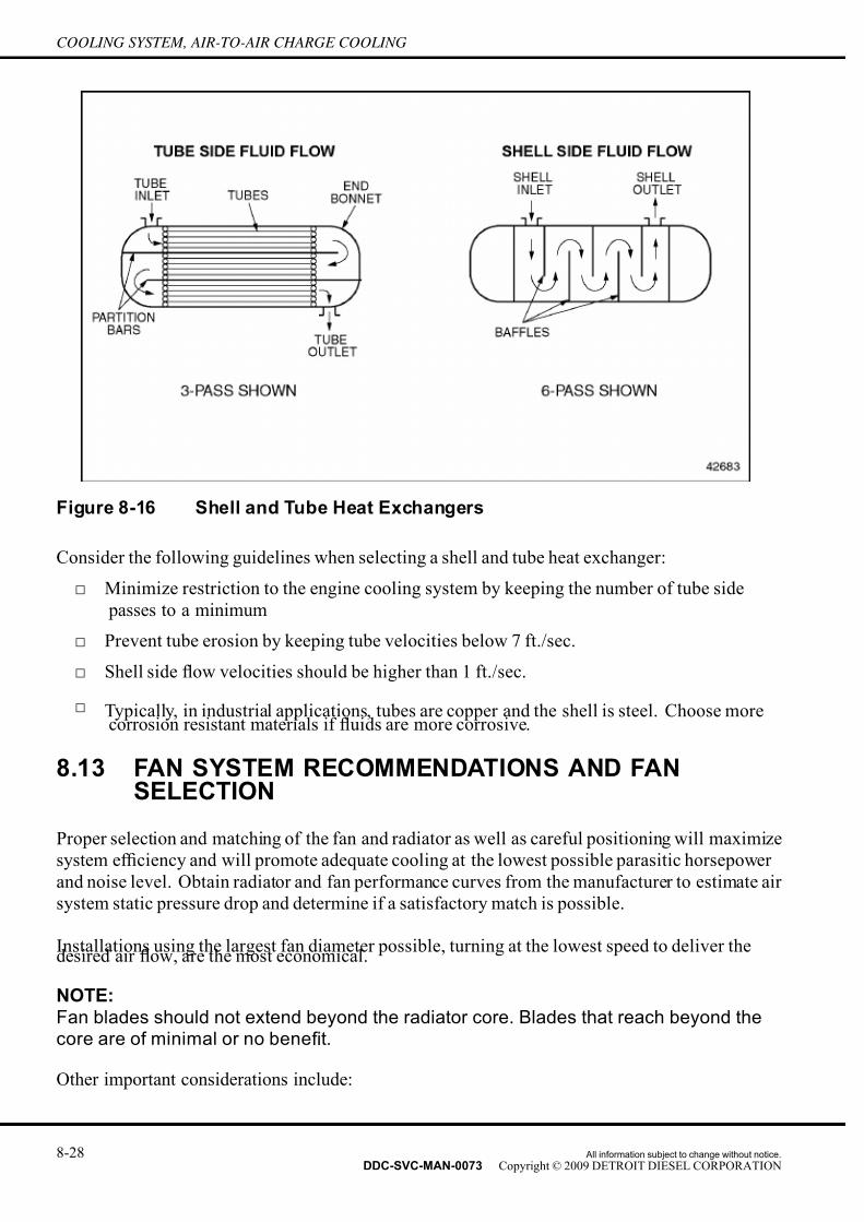
7/14/2019 Dd13-Dd15 a&i Manual
http://slidepdf.com/reader/full/dd13-dd15-ai-manual 126/304
COOLING SYSTEM, AIR-TO-AIR CHARGE COOLING
Figure 8-16 Shell and Tube Heat Exchangers
Consider the following guidelines when selecting a shell and tube heat exchanger:
□ Minimize restriction to the engine cooling system by keeping the number of tube side
passes to a minimum
□ Prevent tube erosion by keeping tube velocities below 7 ft./sec.
□ Shell side flow velocities should be higher than 1 ft./sec.
□ Typically, in industrial applications, tubes are copper and the shell is steel. Choose morecorrosion resistant materials if fluids are more corrosive.
8.13 FAN SYSTEM RECOMMENDATIONS AND FANSELECTION
Proper selection and matching of the fan and radiator as well as careful positioning will maximize
system ef ficiency and will promote adequate cooling at the lowest possible parasitic horsepower
and noise level. Obtain radiator and fan performance curves from the manufacturer to estimate air
system static pressure drop and determine if a satisfactory match is possible.
Installations using the largest fan diameter possible, turning at the lowest speed to deliver thedesired air flow, are the most economical.
NOTE:
Fan blades should not extend beyond the radiator core. Blades that reach beyond thecore are of minimal or no benefit.
Other important considerations include:
8-28 All information subject to change without notice.
DDC-SVC-MAN-0073 Copyright © 2009 DETROIT DIESEL CORPORATION

7/14/2019 Dd13-Dd15 a&i Manual
http://slidepdf.com/reader/full/dd13-dd15-ai-manual 127/304
DD PLATFORM APPLICATION AND INSTALLATION MANUAL
□ Cooling air flow required by the radiator core
□ Cooling air system total pressure drop
□ Space available
□ Noise level limit
□
Fan drive limits□ Fan speed limit
□ Fan weight and support capabilities
□ Fan spacers
Make sure that the manufacturer of the fan knows the tip speed.
8.13.1 BLOWER VS. SUCTION FANS
The application will generally dictate the type of fan to be used (i.e. mobile applications normally
use a suction fan, and stationary units frequently use blower fans). Blower fans are generallymore ef ficient in terms of power expended for a given mass flow, since they will always operate
with lower temperature air as compared to a suction fan. Air entering a suction fan is heated as
it passes through the radiator where a blower fan, even when engine mounted, can receive air
closer to ambient temperatures.
Proper fan spacing from the core and good shroud design are required, so air flow is completely
distributed across the core to obtain high ef ficiency.
A suction fan, when mounted, will generally have the concave side of the blade facing the engine,
whereas a blower fan will have the concave side facing the radiator. A suction fan cannot be made
into a blower fan by simply mounting the fan backwards. Fan rotation must also be correct.
All information subject to change without notice. 8-29DDC-SVC-MAN-0073 Copyright © 2009 DETROIT DIESEL CORPORATION

7/14/2019 Dd13-Dd15 a&i Manual
http://slidepdf.com/reader/full/dd13-dd15-ai-manual 128/304
COOLING SYSTEM, AIR-TO-AIR CHARGE COOLING
Figure 8-17 Blower vs. Suction Fans
8.13.1.1 Fan Performance
Fan curve air flow (m3/min. [ft.3/min.]) is a theoretical output value which is seldom achieved.
This value can be approached with a well formed, tight fitting shroud and proper fan positioning
(fan tip clearances of 1/16 in. [1.59 mm] or less). Consult the fan supplier on how to determine
what the realistic fan air flow delivery will be on the installation.
Select a fan/core match with suf ficient reserve cooling capacity to allow for some degradation.
This degradation occurs as the unit gets older and there is fouling from airborne debris. Theseconditions cause higher air restriction and/or lower heat transfer capability. This is especially true
for applications such as agriculture, earth moving, or mining. Fin density should be as low as
practical to keep air flow high, minimize plugging, and permit easier cleaning.
NOTE:Fin density in excess of 10 fins per inch should be reviewed with Detroit Diesel
Application Engineering.
8-30 All information subject to change without notice.
DDC-SVC-MAN-0073 Copyright © 2009 DETROIT DIESEL CORPORATION

7/14/2019 Dd13-Dd15 a&i Manual
http://slidepdf.com/reader/full/dd13-dd15-ai-manual 129/304
DD PLATFORM APPLICATION AND INSTALLATION MANUAL
Increasing core thickness increases the restriction to air flow. This condition causes fouling
to occur faster.
Consider the following when analyzing fan performance:
□ Speed
□ Static Pressure
□ Horsepower
The following fan law relationships are useful when interpreting basic fan curves:
□ Air flow varies directly with fan speed ft.3/min.2
= (ft.3/min.1) x (r/min.
2) / (r/min.
1)
□ Static head varies with the square of fan speed PS2
= (PS1
) x [(r/min.2) / (r/min.
1)]2
□ Horsepower varies with the cube of fan speed hp2
= (hp1) x [(r/min.
2) / (r/min.
1)]3
Additional factors that affect the installed performance of a fan are listed in the following table.
Installed Fan Factors Affecting Performance
Fan Position Fan to Core Distance, Fan to Engine Distance
Air Flow Restriction
Radiator Core, Engine and Engine Compartment Configuration,
Grills and Bumpers, Air Conditioning Condenser, Air-to-
Oil Cooler, Air-to-Air Cores
Shroud
Shroud-to-Fan Tip Clearance, Shroud-to-Fan Position, Shroud
Type (i.e. Ring, Box, Venturi), Shroud-to-Core Seal, Shutters,
Bug Screens, and Winterfronts
Table 8-2 Installed Fan Performance Factors
Typical fan performance graphs have total pressure curves and power absorption curves for a
given speed of rotation. The pressure, measured in water gage, represents the resistance to flow.
The higher the resistance, the lower the flow. The fan horsepower absorption follows a similar, but not exactly the same, characteristic to the pressure curve. Depending on the installed system
characteristics, the fan operates only at one point of water gage and power.
All information subject to change without notice. 8-31DDC-SVC-MAN-0073 Copyright © 2009 DETROIT DIESEL CORPORATION
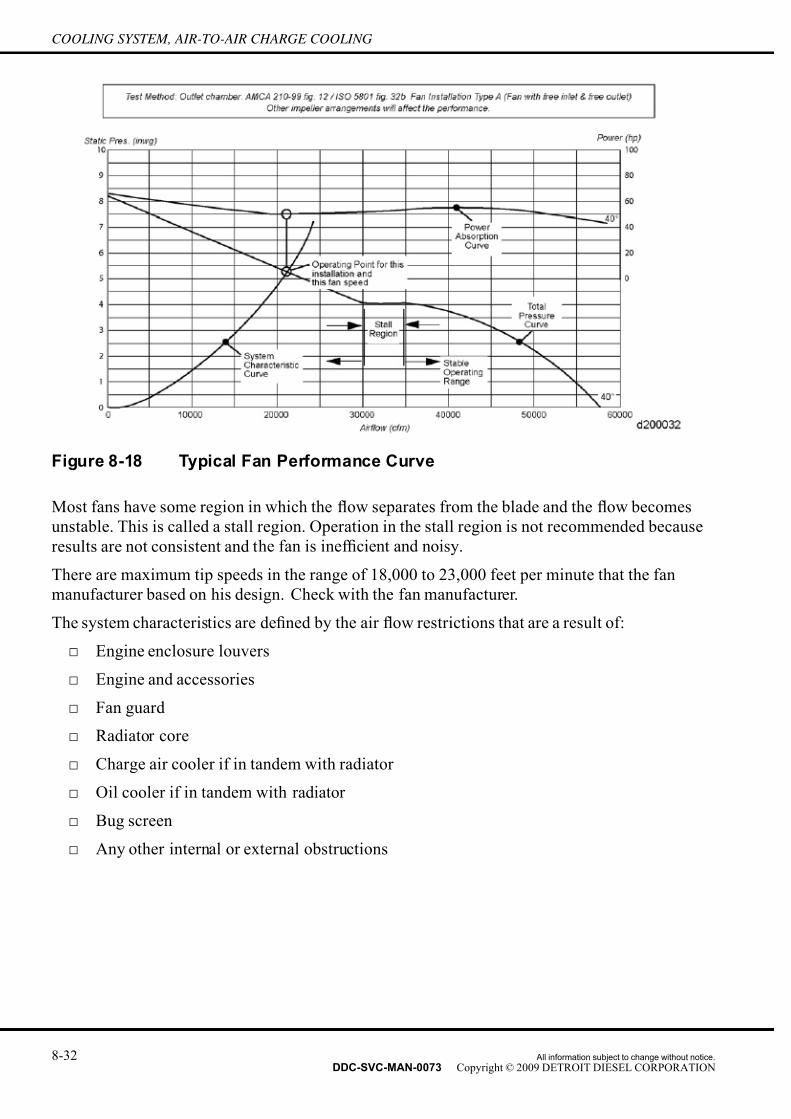
7/14/2019 Dd13-Dd15 a&i Manual
http://slidepdf.com/reader/full/dd13-dd15-ai-manual 130/304
COOLING SYSTEM, AIR-TO-AIR CHARGE COOLING
Figure 8-18 Typical Fan Performance Curve
Most fans have some region in which the flow separates from the blade and the flow becomes
unstable. This is called a stall region. Operation in the stall region is not recommended because
results are not consistent and the fan is inef ficient and noisy.
There are maximum tip speeds in the range of 18,000 to 23,000 feet per minute that the fan
manufacturer based on his design. Check with the fan manufacturer.
The system characteristics are defined by the air flow restrictions that are a result of:
□ Engine enclosure louvers
□ Engine and accessories
□ Fan guard
□ Radiator core
□ Charge air cooler if in tandem with radiator
□ Oil cooler if in tandem with radiator
□ Bug screen
□ Any other internal or external obstructions
8-32 All information subject to change without notice.
DDC-SVC-MAN-0073 Copyright © 2009 DETROIT DIESEL CORPORATION
7/14/2019 Dd13-Dd15 a&i Manual
http://slidepdf.com/reader/full/dd13-dd15-ai-manual 131/304
DD PLATFORM APPLICATION AND INSTALLATION MANUAL
NOTICE:
The fan should never operate in the stall area, where a smallchange in static pressure results in no change in air flow.
NOTICE:
The air side of the cooling system is critical and a change in theair flow will generally have a greater impact on cooling than asimilar percentage change in coolant flow.
Consider these additional factors to determine actual fan performance at worst case operating
conditions.
□ Air temperature
□ Atmospheric pressure
PERSONAL INJURY
To avoid injury from rotating belts and fans, do not remove
and discard safety guards.
Fan curves are generated at standard conditions (77°F [25°C] 0 elevation). If the fan is operating
in different temperature or pressure (altitude) than standard the performance must be adjusted.
8.13.1.2 Fan Position
Fan position relative to the radiator depends on the fan diameter and the radiator frontal area.
Position the fan further away from the core as the fan swept area becomes less than the radiator
frontal area. This allows the air to spread over the full core area. The fan will not spread air over
the entire core area if it is mounted too close to the radiator.
The optimum position of the fan blade on a blower or suction fan with respect to the shroud
opening is dependent on the fan design as well as the many variables associated with an
installation. Different system performance may occur for the same fan positions in different
applications due to air flow restriction and flow obstructions. Consult the fan manufacturer for
assistance in optimizing the fan positioning.
Keep fan tip-to-shroud clearance to a minimum because it influences air flow and noise level
significantly. Minimum clearance is achieved by using a shroud with a round opening. An
adjustable fan shroud is recommended if the fan pulley is adjustable for belt tightening. Consider
allowances for engine/radiator movement when determining tip clearance.
Consider components located behind the fan so air flow is not adversely affected or vibration
introduced to the fan. These conditions will cause premature failures, or increased noise, or
both. Fan height is also important.
All information subject to change without notice. 8-33DDC-SVC-MAN-0073 Copyright © 2009 DETROIT DIESEL CORPORATION

7/14/2019 Dd13-Dd15 a&i Manual
http://slidepdf.com/reader/full/dd13-dd15-ai-manual 132/304
COOLING SYSTEM, AIR-TO-AIR CHARGE COOLING
The use of fan spacers on DD Platform engines are allowed only when a fan drive configuration
review and/or vibration testing has been completed. Consult with DDC Application Engineering
for assistance.
8.13.1.3 Fan Shrouds
The use of a fan shroud is required for achieving good cooling system performance. A properlydesigned shroud will distribute the air across the core more uniformly, increase core air flow, and
prevent air recirculation around the fan. Seal holes and seams in the shroud. An air tight seal
between the shroud and the radiator core will maximize air flow through the core.
There are three basic types of shrouds: the well rounded entrance venturi shroud, the ring shroud,
and the box shroud. The ring and box type shrouds are most common because they are easier to
fabricate.
Figure 8-19 Fan Shroud Types
8-34 All information subject to change without notice.
DDC-SVC-MAN-0073 Copyright © 2009 DETROIT DIESEL CORPORATION

7/14/2019 Dd13-Dd15 a&i Manual
http://slidepdf.com/reader/full/dd13-dd15-ai-manual 133/304
DD PLATFORM APPLICATION AND INSTALLATION MANUAL
8.13.1.4 Fan System Assemblies
Do not exceed the design limits of any component when OEM components such as fans, fan
drives, spacers, etc. are attached to Detroit Diesel supplied components (fan hub and pulley
assemblies). Vibration tests must be performed when the customer wants to use a fan system
not previously approved by DDC.
8.13.1.5 Fan Drives
The DD Platform engines provide a 10–groove poly V fan drive. Refer to Accessory Drive
System section for specifications and belt configuration data.
8.13.1.6 Baf fles to Prevent Air Recirculation
Use baf fles around the perimeter of the radiator assembly to prevent hot air which has passed
through the radiator core from being recirculated back through the core. The cooling capability of
the system may be seriously hindered if this baf fling is not utilized.
8.13.1.7 Shutters
Shutters are not required under most operating conditions with a properly designed cooling
system. Shutters may improve performance under extreme cold ambient conditions and long term
idling or light loading. Improperly installed or maintained devices may lead to reduced engine
life, loss of power, and poor fuel economy.
Shutters should open approximately 3°C (5°F) before the thermostat start to open temperature.
The shutter control should sense engine water out (before thermostat) temperature and the probe
must be fully submerged in coolant flow.
8.13.1.8 Winterfronts
Winterfronts are not required under most operating conditions with a properly designed cooling
system. Some operators reduce the air flow through the radiator during cold weather operation
to increase engine operating temperature. Consider on/off fans and shutters if long term idling
during severe cold weather is necessary.
Improperly used winterfronts may cause excessive temperatures of coolant, oil, and charge air.
This condition can lead to reduced engine life, loss of power, and poor fuel economy. Winterfronts
may also put abnormal stress on the fan and fan drive components.
Never totally close or apply the winterfront directly to the radiator core. At least 25% of the area
in the center of the gr ill should remain open at all times. All monitoring, warning, and shutdown
devices should be properly located and in good working condition.
All information subject to change without notice. 8-35DDC-SVC-MAN-0073 Copyright © 2009 DETROIT DIESEL CORPORATION
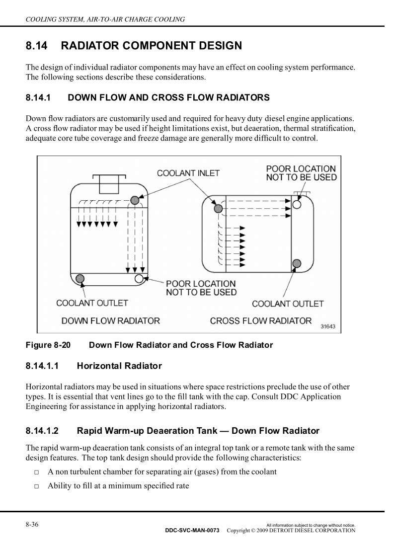
7/14/2019 Dd13-Dd15 a&i Manual
http://slidepdf.com/reader/full/dd13-dd15-ai-manual 134/304
COOLING SYSTEM, AIR-TO-AIR CHARGE COOLING
8.14 RADIATOR COMPONENT DESIGN
The design of individual radiator components may have an effect on cooling system performance.
The following sections describe these considerations.
8.14.1 DOWN FLOW AND CROSS FLOW RADIATORS
Down flow radiators are customarily used and required for heavy duty diesel engine applications.
A cross flow radiator may be used if height limitations exist, but deaeration, thermal stratification,
adequate core tube coverage and freeze damage are generally more dif ficult to control.
Figure 8-20 Down Flow Radiator and Cross Flow Radiator
8.14.1.1 Horizontal Radiator
Horizontal radiators may be used in situations where space restrictions preclude the use of other
types. It is essential that vent lines go to the fill tank with the cap. Consult DDC Application
Engineering for assistance in applying horizontal radiators.
8.14.1.2 Rapid Warm-up Deaeration Tank — Down Flow Radiator
The rapid warm-up deaeration tank consists of an integral top tank or a remote tank with the same
design features. The top tank design should provide the following characteristics:
□ A non turbulent chamber for separating air (gases) from the coolant
□ Ability to fill at a minimum specified rate
8-36 All information subject to change without notice.
DDC-SVC-MAN-0073 Copyright © 2009 DETROIT DIESEL CORPORATION

7/14/2019 Dd13-Dd15 a&i Manual
http://slidepdf.com/reader/full/dd13-dd15-ai-manual 135/304
DD PLATFORM APPLICATION AND INSTALLATION MANUAL
□ Adequate expansion and deaeration volume as well as suf ficient coolant volume so the
system will operate satisfactorily with partial loss of coolant
□ Impose a positive head on the water pump
□ Prevent coolant flow through the radiator core during closed thermostat operation
□ Prevent introduction of air into the cooling system during maximum tilt or angle operation
8.14.1.3 Remote Mounted Radiators/Heat Exchanger
Consult an authorized distributor, radiator supplier, or DDC Application Engineering when
remote (i.e. non engine driven fans) mounted radiators/heat exchangers are being considered as
many variables must be considered for each application. The requirements that must be met
for remote mount are:
□ Standard DDC installation and test requirements including restriction to flow and coolant
flow rate
□ Maximum allowable static head pressure is 32 ft. of water column with a pressure cap, 50
ft. of water column with an open system
□ Installations where flow rate restrictions cannot be met may require using an inline pump
8.14.1.4 Integral Top Tank
The following top tank component guidelines are provided to assist in the design of a new tank, to
critique existing tanks, and to troubleshoot problem cooling systems.
All information subject to change without notice. 8-37DDC-SVC-MAN-0073 Copyright © 2009 DETROIT DIESEL CORPORATION

7/14/2019 Dd13-Dd15 a&i Manual
http://slidepdf.com/reader/full/dd13-dd15-ai-manual 136/304
COOLING SYSTEM, AIR-TO-AIR CHARGE COOLING
Figure 8-21 Rapid Warm-up Down Flow Radiator Top Tank
The guidelines for the design of an integral top tank are listed in tables.
8-38 All information subject to change without notice.
DDC-SVC-MAN-0073 Copyright © 2009 DETROIT DIESEL CORPORATION

7/14/2019 Dd13-Dd15 a&i Manual
http://slidepdf.com/reader/full/dd13-dd15-ai-manual 137/304
DD PLATFORM APPLICATION AND INSTALLATION MANUAL
Component Guidelines
Locate the standpipe(s) as far away from radiator inlet(s) as practical and center over core.
This is the area of least coolant turbulence, thus best for separating air out of the coolant.
Use 1 or 2 standpipes with 0.25 in. (6.35 mm) inside diameter (general rule).
Bottom of tube must not protrude below baf fle.Standpipe(s)
Top of tube must extend above hot full coolant level. The flow must be directed away from
the low coolant level sensor, as well as the filler neck and/or pressure relief valve opening.
This minimizes coolant loss.
A clearance of 1 in. (25.4 mm) or more should be maintained between the top of the radiator
core and the bottom of the top tank baf fle. This produces a good transition of the coolant flow
and enhances air separation from the coolant.Baf fle
Seal baf fle completely so the only flow path between the deaeration tank and the radiator
core is through the standpipe(s). This is essential for proper engine warm-up, preventing top
tank coolant agitation, and providing a positive head on the water pump.
Use a vortex baf fle to prevent formation of a coolant vortex. This also permits maximum
usage of top tank coolant volume.Vortex Baf fle
A vertical baf fle is preferred. Horizontal vortex baf fles at the fill line opening may hinder
the venting of trapped air.
The recommended minimum inside diameter is 1 in. (25.4 mm).
Fill line connections (fittings) must not reduce the minimum inside diameter requirement.Locate the fill line as low as possible above the baf fle and at the center of the tank. This
minimizes uncovering the fill opening and drawing air into the cooling system during vehicle
operations.Fill Line and
ConnectionsMake the engine connection as close to the water pump inlet as practical. This will provide
maximum head to the water pump and minimize heat migration to the radiator core, resulting
in quicker engine warm-up. Avoid connecting the fill line to the coolant bypass circuit. A
continuous downward slope (including fittings) must be maintained from the top tank to the
water pump inlet to ensure good filling capabilities.
Locate the vent line at the top of the top tank above the coolant level in the deaeration space.
The recommended line size is 3/16 in. (4.76 mm) inside diameter
Do not direct deaeration line coolant flow toward the fill neck, pressure relief valve openings,
or low coolant level sensor
Vent (deaeration)
Line – High Position
(above coolant
level) All vent lines must maintain a continuous downward slope
Locate the radiator inlet as low as possible with at least the lower half of the inlet below the
baf fle level to minimize air trapped during fill.
The inside diameter of the inlet should match the inside diameter of the thermostat housing.
Design the radiator inlet to uniformly spread coolant under the baf fle.
The radiator inlet must be sealed from top tank
Radiator Inlet
No vent holes. Extend the fill neck into the tank to establish the cold coolant full level,
allowing for expansion (6%) and deaeration (2%) volume.
Table 8-3 Top Tank Component Guidelines — Standpipe(s), Baf fle, VortexBaf fle, Fill Line and Connections, Vent Line, and Radiator Inlet
All information subject to change without notice. 8-39DDC-SVC-MAN-0073 Copyright © 2009 DETROIT DIESEL CORPORATION

7/14/2019 Dd13-Dd15 a&i Manual
http://slidepdf.com/reader/full/dd13-dd15-ai-manual 138/304
COOLING SYSTEM, AIR-TO-AIR CHARGE COOLING
Component Guidelines
Select the fill neck size capable of accepting highest rated pressure cap required for
application
The fill neck cap must provide safe release of system pressure upon removal of the cap
when a separate pressure relief valve is used.Fill Neck
Locate the fill neck at the top center of the top tank. This will ensure a co mplete fill if
unit is in a tilted position.
Fill Neck Vent HoleA 1/8 in. (3.18 mm) vent hole located at the top of the fill neck extension is required for
venting air and preventing coolant loss.
Location must be above the satisfactory drawdown coolant level. This is generally a
height representing 98% of the drawdown quantity.
Coolant flow and/or splash from deaeration line and standpipe(s) must not contact
sensor. A shroud around the sensor may be beneficial.
Low Coolant Level
Sensor
Locating the sensor in the middle of the tank will minimize tilt operation sensitivity.
Table 8-4 Top Tank Component Guidelines— Fill Neck, Fill Neck Vent Hole,and Coolant Level Sensor
General guidelines for top tank design, critique, or troubleshooting are:
□ Increasing top tank depth permits maximum usage of coolant volume and reduces tilt
operation problems.
□ Consider hose fitting inside diameters when determining vent and fill line inside diameter
requirements.
□ Low fill line flow velocity (large inside diameter line) will generally improve drawdown
capacity and maintain higher pressure on the water pump.
□ Oversized and/or excessive number of deaeration line(s) and standpipe(s) can result in
poor deaeration and drawdown capabilities and increases coolant flow bypassing theradiator core.
□ Undersizing deaeration line(s) and standpipe(s) may not provide adequate deaeration and
they can become plugged easier.
□ Make observations of top tank agitation, deaeration and fill line(s), flow direction, and
velocity during both open and closed thermostat operations (throughout engine speed
range), to determine satisfactory system design. The observations are especially helpful
during fill and drawdown evaluation tests.
□ A sight glass in the radiator top tank to determine proper coolant level will eliminate
unnecessary removal of the radiator cap.
8.14.1.5 Remote Tank
The design of the remote tank must provide the same features as the integral top tank design. The
guidelines for the radiator inlet tank are listed in the following table.
8-40 All information subject to change without notice.
DDC-SVC-MAN-0073 Copyright © 2009 DETROIT DIESEL CORPORATION

7/14/2019 Dd13-Dd15 a&i Manual
http://slidepdf.com/reader/full/dd13-dd15-ai-manual 139/304
DD PLATFORM APPLICATION AND INSTALLATION MANUAL
Figure 8-22 Remote Surge Tank Design for Rapid Warm-up Cooling System
Component and
LocationGuidelines
Must be large enough so air can be separated from the coolant.
Radiator Inlet Tank The deaeration line from the radiator inlet tank to the remote/top tank must be
at the highest point of each and generally as far away from the inlet as practical.
Locate tank as high as practical. The bottom of the tank should be above the
rest of the cooling system. This will prevent coolant level equalization problems.
Location Generally, low mounted tanks make filling the system more dif ficult, especially
near the end of the fill, because of small head differential. Also, equalization of the coolant level occurs during engine stop or low speed operation.
Table 8-5 Component Design and Location Guidelines for the Remote Top
Tank
All information subject to change without notice. 8-41DDC-SVC-MAN-0073 Copyright © 2009 DETROIT DIESEL CORPORATION

7/14/2019 Dd13-Dd15 a&i Manual
http://slidepdf.com/reader/full/dd13-dd15-ai-manual 140/304
COOLING SYSTEM, AIR-TO-AIR CHARGE COOLING
Figure 8-23 Down Flow Radiator Inlet Tank Deaeration Line Boss Position
8.14.1.6 Radiator Bottom Tank
Consider the following guidelines when designing the radiator bottom tank.
□ Locate the coolant opening diagonally opposite the inlet tank opening or as far away as is
practical. This provides uniform distribution of the coolant across the core and prevents
short circuiting.
8-42 All information subject to change without notice.
DDC-SVC-MAN-0073 Copyright © 2009 DETROIT DIESEL CORPORATION

7/14/2019 Dd13-Dd15 a&i Manual
http://slidepdf.com/reader/full/dd13-dd15-ai-manual 141/304
DD PLATFORM APPLICATION AND INSTALLATION MANUAL
Figure 8-24 Coolant Inlet/Outlet Locations
□ Inside diameter of outlet must be greater than, or equal to respective inlet connections.
□ A well rounded coolant outlet exit area is preferred to minimize restriction and aeration.
Figure 8-25 Radiator Outlet Contour
□ Depth of the tank should be no less than the diameter of the outlet pipe to minimize
restriction.
All information subject to change without notice. 8-43DDC-SVC-MAN-0073 Copyright © 2009 DETROIT DIESEL CORPORATION

7/14/2019 Dd13-Dd15 a&i Manual
http://slidepdf.com/reader/full/dd13-dd15-ai-manual 142/304
COOLING SYSTEM, AIR-TO-AIR CHARGE COOLING
□ Locate a drain plug/cock on the lowest portion of the cooling system to ensure complete
draining and removal of any sediment (remember that the bottom tank may not be the
lowest point).
8.14.1.7 Coolant Pressure Control Caps and Relief Valves
Pressurizing the cooling system:
□ Reduces boiling
□ Prevents coolant loss due to evaporation
□ Maintains water pump performance
Pressurization is obtained by the expansion of the coolant as it is heated and controlled through
the use of an integral pressure/fill cap or a separate relief valve.
NOTICE:
System pressurization will not occur if pressure/fill cap is installed
when coolant is hot.
Locate the pressure control device high in the deaeration tank above the hot coolant level to
minimize coolant loss and dirt contamination of the relief valve seat.
HOT COOLANT
To avoid scalding from the expulsion of hot coolant, never
remove the cooling system pressure cap while the engine isat operating temperature. Wear adequate protective clothing
(face shield, rubber gloves, apron, and boots). Remove the
cap slowly to relieve pressure.
The pressure valve (in the normally closed position) should maintain top tank pressure to within
+/- 6.9 kPa (+/- 1 psi) of the rating stamped on top of the cap/valve. The valve will lift off the
seat as pressure exceeds the specified rating.
8-44 All information subject to change without notice.
DDC-SVC-MAN-0073 Copyright © 2009 DETROIT DIESEL CORPORATION

7/14/2019 Dd13-Dd15 a&i Manual
http://slidepdf.com/reader/full/dd13-dd15-ai-manual 143/304
DD PLATFORM APPLICATION AND INSTALLATION MANUAL
Figure 8-26 Pressure Control Cap — Pressure Valve Open
A vacuum actuated valve is incorporated in the assembly to prevent collapse of hoses and other
parts as the coolant cools.
Figure 8-27 Pressure Control Cap — Vacuum Valve Open
The filler neck cap must provide for a safe release of the pressure upon cap removal if a separate
pressure relief valve is used.
Inspect the valve/cap, periodically, to ensure components are clean, not damaged, and in good
operating order.
All information subject to change without notice. 8-45DDC-SVC-MAN-0073 Copyright © 2009 DETROIT DIESEL CORPORATION

7/14/2019 Dd13-Dd15 a&i Manual
http://slidepdf.com/reader/full/dd13-dd15-ai-manual 144/304
COOLING SYSTEM, AIR-TO-AIR CHARGE COOLING
A 82.7 kPa (12 psi) pressure cap is required for most systems and applications. See
www.detroitdiesel.com to verify required minimum pressure cap rating. Consider higher pressure
rated caps for operation at increased altitudes.
Figure 8-28 Effect of Altitude and Pressure Caps
8.14.1.8 Thermostat
A full blocking thermostat is used to automatically regulate coolant temperature by controlling
the coolant flow to the radiator and engine bypass circuit. A full blocking thermostat design inthe full open position (15° to 17°F [8° to 9°C]) above the start to open temperature) controls the
engine bypass circuit, and provides maximum coolant flow to the radiator.
The start-to-open thermostat temperature varies with the rating and model. The engine coolant
temperature will be controlled at the thermostat start to open value, under normal operating
conditions.
8-46 All information subject to change without notice.
DDC-SVC-MAN-0073 Copyright © 2009 DETROIT DIESEL CORPORATION

7/14/2019 Dd13-Dd15 a&i Manual
http://slidepdf.com/reader/full/dd13-dd15-ai-manual 145/304
DD PLATFORM APPLICATION AND INSTALLATION MANUAL
NOTICE:
Never operate the engine without thermostats.
8.14.1.9 Coolant Sensor Devices
Engine coolant temperature monitors (gages, alarms, shutdowns, fan and shutter control switches,etc.) must be durable, reliable and accurate. Submerge the probe completely in a high flow stream
to sense uniform coolant temperature. Locate the probe in an area without air pockets, or mount it
in a place where it will not be affected by coolant being returned from parallel circuits such as
heater, air compressor, and aftercooler return lines.
The coolant temperature monitor may not respond fast enough to prevent engine damage if a large
quantity of coolant is suddenly lost, or if the water pump becomes air bound. Low Coolant Level
Sensors are mandatory with DD Platform engines.
Temperature Gauges: Every temperature gage should have suf ficient markings to allow an
operator to determine actual operating temperature. The temperature range should go beyond
99°C (210°F) so the operator will know if the maximum coolant temperature is being exceeded.Maintain accuracy of +/- 3°C (5°F) to prevent inaccurate indication of either hot or cold running
engine conditions.
Temperature Alarms: An auxiliary warning device (audible or visible) should be included if a
digital gage is used. Set temperature alarm units at coolant temperature level that is 3°C (5°F)
above the maximum allowable coolant temperature. Accuracy should be +/- 3°C (5°F). Locate
each alarm sensor before the thermostat. Special considerations, including testing must be done
when a coolant recovery system is used.
Temperature Shutdowns: Set temperature shutdown devices for a coolant temperature level of
104°C (220°F). Accuracy should be +/- 1°C (2°F).
Low Coolant Level Sensor: Locate the sensor for low engine coolant level in the top tank. See
tank design section for additional recommendations.
Shutter Control Switches: Mount shutter switches before the engine thermostat so they can
sense engine coolant temperature. The various temperature control devices (shutters, fan drives
and thermostats) must operate in proper sequence to prevent coolant temperature instability or
overheat conditions.
The recommended temperature settings of the various coolant sensor devices can be seen in
the following illustration.
All information subject to change without notice. 8-47DDC-SVC-MAN-0073 Copyright © 2009 DETROIT DIESEL CORPORATION

7/14/2019 Dd13-Dd15 a&i Manual
http://slidepdf.com/reader/full/dd13-dd15-ai-manual 146/304
COOLING SYSTEM, AIR-TO-AIR CHARGE COOLING
Figure 8-29 Nominal Settings For Coolant Temperature Control Devices — 190°
8.14.1.10 Coolant Recovery System
Use the coolant recovery tank system only when adequate expansion, drawdown, and deaeration
volume cannot be designed into the radiator or remote top tanks.
8-48 All information subject to change without notice.
DDC-SVC-MAN-0073 Copyright © 2009 DETROIT DIESEL CORPORATION

7/14/2019 Dd13-Dd15 a&i Manual
http://slidepdf.com/reader/full/dd13-dd15-ai-manual 147/304
DD PLATFORM APPLICATION AND INSTALLATION MANUAL
Figure 8-30 Cooling System Design (Warm-up — Closed Thermostat)
All information subject to change without notice. 8-49DDC-SVC-MAN-0073 Copyright © 2009 DETROIT DIESEL CORPORATION

7/14/2019 Dd13-Dd15 a&i Manual
http://slidepdf.com/reader/full/dd13-dd15-ai-manual 148/304
COOLING SYSTEM, AIR-TO-AIR CHARGE COOLING
Figure 8-31 Cooling System Design (Stabilized Temperature — OpenThermostat)
The total coolant volume increases as the engine coolant temperature rises. The pressure valve in
the pressure control cap will open due to this pressure causing coolant to flow into the coolant
recovery tank.
8-50 All information subject to change without notice.
DDC-SVC-MAN-0073 Copyright © 2009 DETROIT DIESEL CORPORATION

7/14/2019 Dd13-Dd15 a&i Manual
http://slidepdf.com/reader/full/dd13-dd15-ai-manual 149/304
DD PLATFORM APPLICATION AND INSTALLATION MANUAL
When the tank is open to the atmosphere, the coolant will be drawn back into the top tank through
the vacuum valve in the pressure control cap when the coolant temperature decreases. The total
coolant volume decreases as the engine coolant temperature falls.
Figure 8-32 Cooling System Design (Cool-down — Closed Thermostat)
All information subject to change without notice. 8-51DDC-SVC-MAN-0073 Copyright © 2009 DETROIT DIESEL CORPORATION
7/14/2019 Dd13-Dd15 a&i Manual
http://slidepdf.com/reader/full/dd13-dd15-ai-manual 150/304
COOLING SYSTEM, AIR-TO-AIR CHARGE COOLING
The coolant recovery tank must have suf ficient volume to meet the coolant expansion requirements
of the entire cooling system. A minimum of 6% capacity of the total cooling system vo lume
should exist between the hot and cold levels in the recovery tank.
Mount the coolant recovery tank as close as possible to the pressure control cap.
Locating the tank as high as possible with respect to the control cap may make leaks easier to find
and may prevent air from being drawn into the system.The air-tight line connections become more crucial when the tank is mounted low. Should a leak
occur under these conditions air could be drawn into the system.
The coolant recovery line between the tank and radiator is typically 0.25 in. (6.35 mm) I.D.
Connect this line as close to the bottom of the tank as possible. A standpipe may be used in the
tank to prevent sediment from being drawn into the cooling system.
Meet the following design criteria to achieve a properly functioning coolant recovery system:
□ Use an air tight pressure cap
□ Install and maintain air tight seals on either ends of the line
□ Ensure that the coolant level in the tank does not go below the level where the coolant
recovery line connects to the recovery tank
Do not visually check the recovery tank because it may give a false indication of the coolant level
in the entire cooling system. Use a sight glass in the top tank if a visual check is necessary.
Use a pressure control cap which has a design similar to the cap. A minimum of 1 bar (87.2
kPa, 12 psi) pressure cap is required.
HOT COOLANT
To avoid scalding from the expulsion of hot coolant, never
remove the cooling system pressure cap while the engine isat operating temperature. Wear adequate protective clothing
(face shield, rubber gloves, apron, and boots). Remove the
cap slowly to relieve pressure.
Do not use a cap design in which the vacuum valve opens directly to the atmosphere.
Locate the pressurized control cap at the highest point of the top tank. Do not design a filler neck
onto the cap to ensure that air is not trapped at the top of the top tank.
8-52 All information subject to change without notice.
DDC-SVC-MAN-0073 Copyright © 2009 DETROIT DIESEL CORPORATION
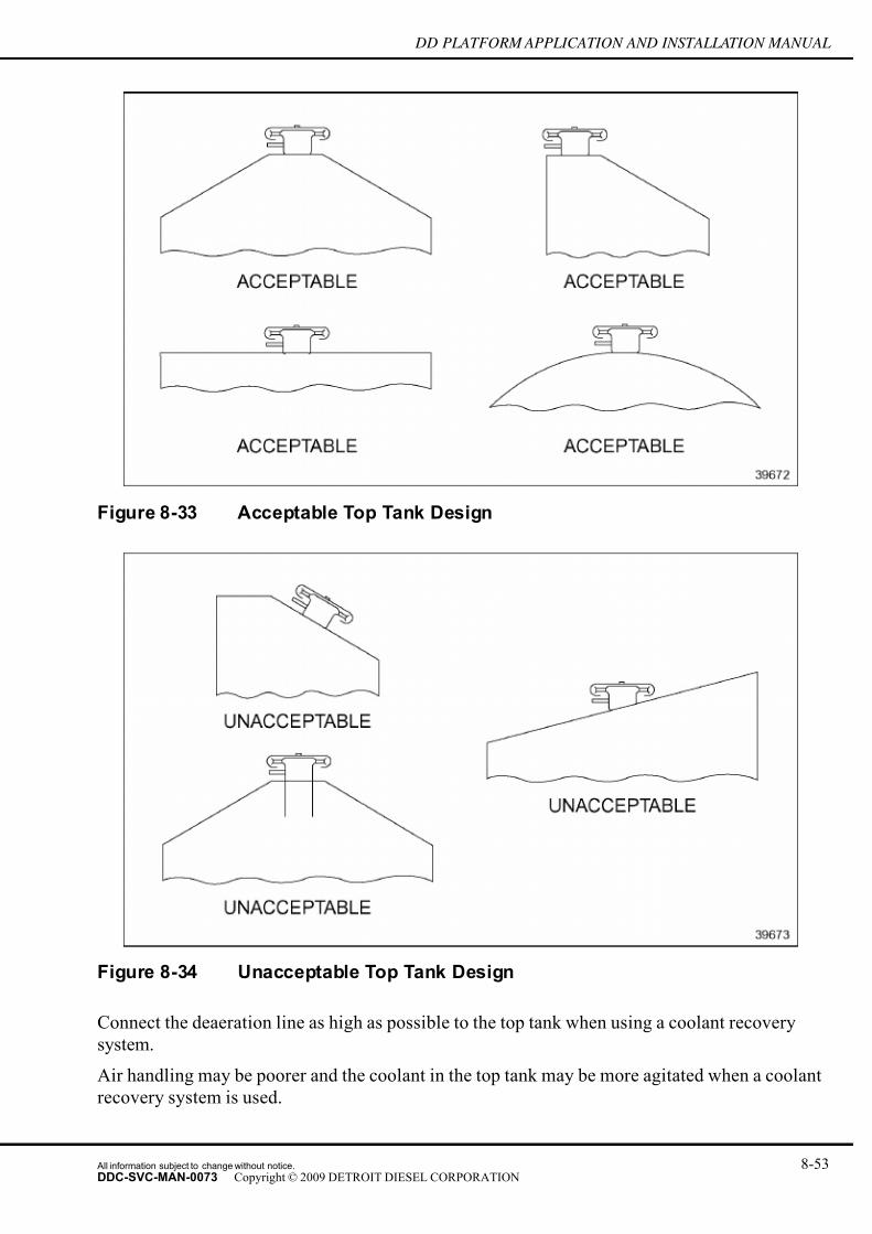
7/14/2019 Dd13-Dd15 a&i Manual
http://slidepdf.com/reader/full/dd13-dd15-ai-manual 151/304
DD PLATFORM APPLICATION AND INSTALLATION MANUAL
Figure 8-33 Acceptable Top Tank Design
Figure 8-34 Unacceptable Top Tank Design
Connect the deaeration line as high as possible to the top tank when using a coolant recovery
system.
Air handling may be poorer and the coolant in the top tank may be more agitated when a coolant
recovery system is used.
All information subject to change without notice. 8-53DDC-SVC-MAN-0073 Copyright © 2009 DETROIT DIESEL CORPORATION
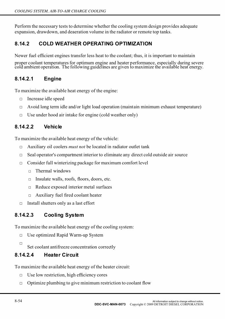
7/14/2019 Dd13-Dd15 a&i Manual
http://slidepdf.com/reader/full/dd13-dd15-ai-manual 152/304
COOLING SYSTEM, AIR-TO-AIR CHARGE COOLING
Perform the necessary tests to determine whether the cooling system design provides adequate
expansion, drawdown, and deaeration volume in the radiator or remote top tanks.
8.14.2 COLD WEATHER OPERATING OPTIMIZATION
Newer fuel ef ficient engines transfer less heat to the coolant; thus, it is important to maintain
proper coolant temperatures for optimum engine and heater performance, especially during severecold ambient operation. The following guidelines are given to maximize the available heat energy.
8.14.2.1 Engine
To maximize the available heat energy of the engine:
□ Increase idle speed
□ Avoid long term idle and/or light load operation (maintain minimum exhaust temperature)
□ Use under hood air intake for engine (cold weather only)
8.14.2.2 Vehicle
To maximize the available heat energy of the vehicle:
□ Auxiliary oil coolers must not be located in radiator outlet tank
□ Seal operator's compartment interior to eliminate any direct cold outside air source
□ Consider full winterizing package for maximum comfort level
□ Thermal windows
□ Insulate walls, roofs, floors, doors, etc.
□ Reduce exposed interior metal surfaces
□ Auxiliary fuel fired coolant heater
□ Install shutters only as a last effort
8.14.2.3 Cooling System
To maximize the available heat energy of the cooling system:
□ Use optimized Rapid Warm-up System
□
Set coolant antifreeze concentration correctly
8.14.2.4 Heater Circuit
To maximize the available heat energy of the heater circuit:
□ Use low restriction, high ef ficiency cores
□ Optimize plumbing to give minimum restriction to coolant flow
8-54 All information subject to change without notice.
DDC-SVC-MAN-0073 Copyright © 2009 DETROIT DIESEL CORPORATION

7/14/2019 Dd13-Dd15 a&i Manual
http://slidepdf.com/reader/full/dd13-dd15-ai-manual 153/304
DD PLATFORM APPLICATION AND INSTALLATION MANUAL
□ Do not hinder air side restriction air flow for good distribution of heat
□ Use inside recirculated air (if window fogging is not a problem)
□ Use booster water pump if required
□ Do not place fuel heaters in the cab/sleeper heater circuits
□
Core and air ducts should favor defrost operation and driver/passenger comfortRefer to www.detroitdiesel.com installation data for recommended heater connect points.
8.14.3 COOLANT HEATERS
Information on coolant heaters can be obtained from Detroit Diesel Application Engineering.
8.14.4 MULTI-DUTY CYCLE
Cooling systems must perform satisfactorily under all operating modes. Consideration must
be given when an engine is used for prime power under several duty cycles such as cranes,
drill/pumping rigs, etc. Cooling system must be sized for the maximum rated load.
8.14.5 OTHER CONSIDERATIONS
Cooling system performance must be reevaluated any time engine, cooling system, vehicle
components, timing, etc., are changed due to potential increased heat load or reduced cooling
system capacity. Conduct a reevaluation of the cooling system if load, duty cycle, or
environmental operating conditions are different than originally approved.
8.15 COOLING SYSTEM EVALUATION TESTS
Cooling tests must be conducted on all new installations and engine re-powers. The same test
must be conducted whenever modifications have been made to the engine or cooling system as
well as changes in load, duty cycle, or environmental operating conditions. This will verify
that the cooling system will perform satisfactorily in the installation by having adequate heat
dissipation capability and coolant flow.
A thorough evaluation will require:
□ Complete description and documentation of the system
□ Adequate instrumentation
□ Proper test preparations
□ Accurate tests
□ Data analysis and documentation
□ Diagnostics (troubleshooting)
□ Corrective action (if necessary)
All information subject to change without notice. 8-55DDC-SVC-MAN-0073 Copyright © 2009 DETROIT DIESEL CORPORATION

7/14/2019 Dd13-Dd15 a&i Manual
http://slidepdf.com/reader/full/dd13-dd15-ai-manual 154/304
COOLING SYSTEM, AIR-TO-AIR CHARGE COOLING
8.15.1 SYSTEM DESCRIPTION
A complete system description must be documented in the Detroit Diesel Vehicle Sign-Off form.
Attach cooling system component prints, installation drawings, photographs, and sketches of
the overall system to the Vehicle Sign-Off.
This information will assist in determining system approval and also serve as a reference point if
future dif ficulties are encountered.
8.15.2 INSTRUMENTATION
The following instrumentation and materials are required to conduct a complete evaluation of
the cooling system:
□ Thermocouples and associated readout equipment
□ Pressure gages and associated hoses and fittings
□ Thermostat
□ Stop watch
□ Light (flashlight, trouble light)
□ Water supply hose
□ Diagnostic data reader or Detroit Diesel Diagnostic Link™ software
□ Engine loading method
□ Tape measure
□ Flowmeters and associated hardware (if necessary)
NOTE: All instrumentation must be calibrated and in good working condition. Size and range
should maintain data accuracy.
8.15.2.1 Thermocouples and Associated Hardware
This section discusses the attributes needed for coolant, air and oil in relation to thermocouples
and associated equipment.
Measure air, engine coolant out, and lube oil gallery temperatures until the coolant and engine
lube oil temperatures are fully stabilized. Other temperature measurements such as engine coolant
in, engine intake air, and exhaust temperatures may be measured to aid in troubleshooting coolingsystem deficiencies.
All thermocouples, wires, and readout equipment must be compatible. All junction points should
have wire insulation completely removed, cleaned, and securely joined for good electrical
continuity. Polarity must also be correct.
Use calibrated matched pairs to obtain accurate temperature differential values.
8-56 All information subject to change without notice.
DDC-SVC-MAN-0073 Copyright © 2009 DETROIT DIESEL CORPORATION

7/14/2019 Dd13-Dd15 a&i Manual
http://slidepdf.com/reader/full/dd13-dd15-ai-manual 155/304
DD PLATFORM APPLICATION AND INSTALLATION MANUAL
A digital readout is preferred and should have 12V (DC) and 110V (60Hz AC) capability. A
remote multi-channel switch can be wired into the circuit if the readout box does no t have
suf ficient positions for all the thermocouples.
Location of the thermocouples is critical. The thermocouples must protrude into a high flow path
and not touch surrounding surfaces. Ambient air thermocouples must be shielded from direct
sunlight and not sense any radiated or recirculated heat sources. Radiator thermocouples must also
be shielded from sunlight. The sump thermocouple must be in the oil while the engine is running.
8.15.2.2 Pressure Gauges and Associated Hardware
To measure water pump inlet pressure, use a381 mm Hg to +20 6.8 kPa (15 in. Hg, +30 psi),
compound gage or 72.6 cm (30 in.) or greater “U” type manometer.
Additional pressure measurements may be required for analysis of the system.
Use a vent at each gage to expel all entrained air and water and ensure no blockage in the circuit.
All hoses must be full of the substance being measured.
NOTE:Locating gages at the same height as the measurement point eliminates the need to
correct the readings.
Hose length should be as short as is practical.
8.15.2.3 Thermostat
Both blocked open and operating thermostats are required. A thermostat must be blocked open to
the proper dimension for obtaining correct data. Full blocking thermostats must be opened so
the coolant bypass circuit is completely shut off. Make a visual check. The oil cooler bypassthermostat must be blocked to the minimum travel distance at full open temperature. Inspect and
replace thermostat seals if necessary.
All information subject to change without notice. 8-57DDC-SVC-MAN-0073 Copyright © 2009 DETROIT DIESEL CORPORATION

7/14/2019 Dd13-Dd15 a&i Manual
http://slidepdf.com/reader/full/dd13-dd15-ai-manual 156/304
COOLING SYSTEM, AIR-TO-AIR CHARGE COOLING
Figure 8-35 Thermostat
8.15.2.4 Sight Glass and Transparent Tubing
Observation of coolant aeration, flow direction, and velocity greatly assists in analyzing test
results and determining system acceptability.
Install a sight glass in the engine water out line between thermostat housing and radiator inlet.
NOTE:
To avoid personal injury such as scalding or eye injury, thick wall transparent tubing mustbe used. Safety straps must be used with the sight glass and flow meters.
NOTICE:
All connections must be secured carefully and be routed so they
do not kink and will not be damaged during testing.
Replace deaeration and fill lines with transparent tubing. It is also helpful to replace coolant
return lines on heater, air compressor, filter, coolant conditioner, and other components that
use engine coolant.
Sight glass and transparent tubing is useful during fill, drain, capacity check, deaeration, flowand pressure vs. engine speed maps, and drawdown tests. These visual aids should be removed
for safety reasons prior to air handling, cooling index, and any other tests where the system is
pressurized and high coolant temperatures are expected.
8-58 All information subject to change without notice.
DDC-SVC-MAN-0073 Copyright © 2009 DETROIT DIESEL CORPORATION

7/14/2019 Dd13-Dd15 a&i Manual
http://slidepdf.com/reader/full/dd13-dd15-ai-manual 157/304
DD PLATFORM APPLICATION AND INSTALLATION MANUAL
8.15.2.5 Graduated Container
An 3 gal (11 L) bucket, graduated in 1 qt. (.95 L) increments is recommended for most co oling
systems.
The container is needed to determine total cooling system capacity, measure coolant removed
during drawdown test, and coolant expelled during air handling test, and measuring water supply
flow rate for fill test.
8.15.2.6 Pressure Cap
The pressure relief cap/valve must be functional and develop rated pressure.
8.15.2.7 Stop Watch
A stop watch is used in conjunction with a graduated bucket to set flow rate for fill test and to
record time to expel all entrained air after filling the system (deaeration time).
8.15.2.8 Light
A flashlight or trouble light held against the sight glass or transparent tubing is helpful in
observing coolant aeration. A light is also useful to look for top tank coolant agitation.
8.15.2.9 Water Supply and Hose
A water supply and hose capable of flowing at minimum 3 gal/min. (11.35 L/min) should be
available to conduct continuous and interrupted fill tests. A flow meter that can regulate rate and
measure capacity is ideal.
Normally a stop watch, graduated bucket, and a valve on the hose are needed to regulate water
flow to the required fill rate.
8.15.2.10 Engine Loading Method
The test facility should provide a method for fully loading the engine, in order to conduct cooling
index tests. The loading method will vary with application and test site location.
8.15.2.11 Tape Measure
Size and distance measurements of radiator assembly, fan components, and other related hardware
are required to complete cooling system evaluation.
All information subject to change without notice. 8-59DDC-SVC-MAN-0073 Copyright © 2009 DETROIT DIESEL CORPORATION

7/14/2019 Dd13-Dd15 a&i Manual
http://slidepdf.com/reader/full/dd13-dd15-ai-manual 158/304
COOLING SYSTEM, AIR-TO-AIR CHARGE COOLING
8.15.2.12 Flowmeters and Associated Hardware
Engine coolant out (radiator in) is the preferred location for measuring radiator flow. Inside
diameter of flowmeters must not cause excessive restriction. Use engine coolant in (radiator out),
only as a last resort because of added inlet restriction to the water pump.
The flowmeter should offer low restriction to the coolant flow, regardless of the type used (turbine,
differential pressure, etc.). Refer to the manufacturers instructions for correct installation,
operation, and limitations of the individual flowmeter.
8.15.3 TEST PREPARATIONS
The following preparations are necessary before conducting the cooling system tests:
1. Confirm all instrumentation and equipment is in good working condition and calibrated.
2. Know how to use and operate all equipment.
3. Understand overall cooling system circuitry and operation, test procedures, and data
analysis.
4. Obtain all available information on the specific cooling system to be evaluated such as
radiator/top tank assembly print, fan/fan drive, shrouds, circuitry, etc. prior to conducting
tests.
HOT COOLANT
To avoid scalding from the expulsion of hot coolant, never remove the cooling system pressure cap while the engine is
at operating temperature. Wear adequate protective clothing(face shield, rubber gloves, apron, and boots). Remove the
cap slowly to relieve pressure.
5. Be sure the test unit represents the final complete package to be released.
6. Check coolant concentration and take sample for possible analysis.
7. Drain entire cooling system completely. This may require removing hoses and even
blowing air through coolant passages.
8. Flush cooling system with water to remove all residual antifreeze solution. Flush systemwith a reputable cleaner if it is contaminated.
9. Install instrumentation, sight glass, and transparent tubing.
10. Disarm high temperature and low coolant shutdown devices for these tests. Shutdown
and alarm settings should be determined.
11. Modify shutter controls, fan controls, and transmissions, if necessary to perform certain
tests correctly.
8-60 All information subject to change without notice.
DDC-SVC-MAN-0073 Copyright © 2009 DETROIT DIESEL CORPORATION

7/14/2019 Dd13-Dd15 a&i Manual
http://slidepdf.com/reader/full/dd13-dd15-ai-manual 159/304
DD PLATFORM APPLICATION AND INSTALLATION MANUAL
12. Know cooling system requirements (specifications) for the application and engine
configuration to be evaluated.
13. Locate test vehicle or equipment on a level surface for all stationary tests (except high
gradeability applications).
8.15.4 TYPES OF TESTS
The following tests and evaluations are normally conducted to determine system acceptability:
□ Fill and Capability Tests
□ Continuous Fill
□ Interrupted Fill
□ Total System Capacity
□ Draining Capability
□ Water Pump Air Test
□ Deaeration Test
□ Drawdown Test
□ Water Flow and Pressure Test
□ Cooling Index Test
The cooling system must be clean. Run qualification tests on a finalized complete package
installed in unit or vehicle.
Perform fill tests with closed thermostats, no pressure cap, and heater, filter circuits, etc. open.
The following factors can cause poor filling capabilities and possible water pump air binding
problems:
□ Fill line routing (horizontal)
□ Drooped deaeration lines
□ Incorrect deaeration line location on the engine or deaeration tank
□ Horizontal vortex baf fle located on the engine or deaeration tank at fill line opening
□ Routing of coolant lines (drooped) not having a continuous slope
□ Coolant trapped in various cooling system components from a previous fill can prevent air
from being purged on the refill
□ Deaeration tank not the highest cooling system component
8.15.4.1 Continuous Fill
Perform the continuous fill test as follows:
All information subject to change without notice. 8-61DDC-SVC-MAN-0073 Copyright © 2009 DETROIT DIESEL CORPORATION

7/14/2019 Dd13-Dd15 a&i Manual
http://slidepdf.com/reader/full/dd13-dd15-ai-manual 160/304
COOLING SYSTEM, AIR-TO-AIR CHARGE COOLING
1. Fill the system with water at a constant 3 gal/min. (11.35 L/min) rate with cooling system
completely empty and all drains closed, until fill neck over flows. The fill must be timed so
the amount of water can be determined.
2. Start engine (no pressure cap) and idle for approximately two minutes.
3. Increase engine speed slowly to high idle and hold for about one minute.
4. Reduce speed to idle and cycle up and down several times.
5. Make continuous observations throughout the test for aeration, coolant flow direction, and
coolant agitation in the deaeration tank.
[a] Stop engine.
[b] Add coolant as required to achieve cold full level and record amount. Coolant should
be at the bottom of the fill neck extension or to the recommended cold full mark at
the conclusion of the test. A satisfactory fill will not require more make up volume
than the satisfactory drawdown capacity of the system. The amount of water during
the initial fill plus the make up will equal the total system capacity.
6. Verify that no flow in either direction occurs in the bleed line from the radiator to a remotemounted deaeration tank system while the thermostat is closed.
[a] Verify that no air is being drawn down the fill line as a result of improper engine
deaeration line size or location in deaeration tank and excessive agitation of the
coolant.
8.15.4.2 Interrupted Fill
Perform the interrupted fill test as follows:
1. After completing the continuous fill test, drain approximately half the coolant from a full
system and start refilling the system following the previous procedure (3 gpm.) untilthe fill neck over flows).
2. Start the engine and measure make-up water as described in the continuous fill test.
3. Confirm that make-up water volume does not exceed satisfactory drawdown capacity and
that the water pump did not become air bound.
8.15.4.3 Bucket Fill
Perform the bucket fill test as follows:
1. Pour a measured amount of water into the cooling system fill neck as quickly as possible,using the 2–3 gallon bucket. Allow coolant level to come to rest.
2. Repeat this procedure until fill neck over flows. The measured amount of water is the
initial fill volume.
3. Start the engine and measure make-up water as described in the continuous fill test.
8-62 All information subject to change without notice.
DDC-SVC-MAN-0073 Copyright © 2009 DETROIT DIESEL CORPORATION
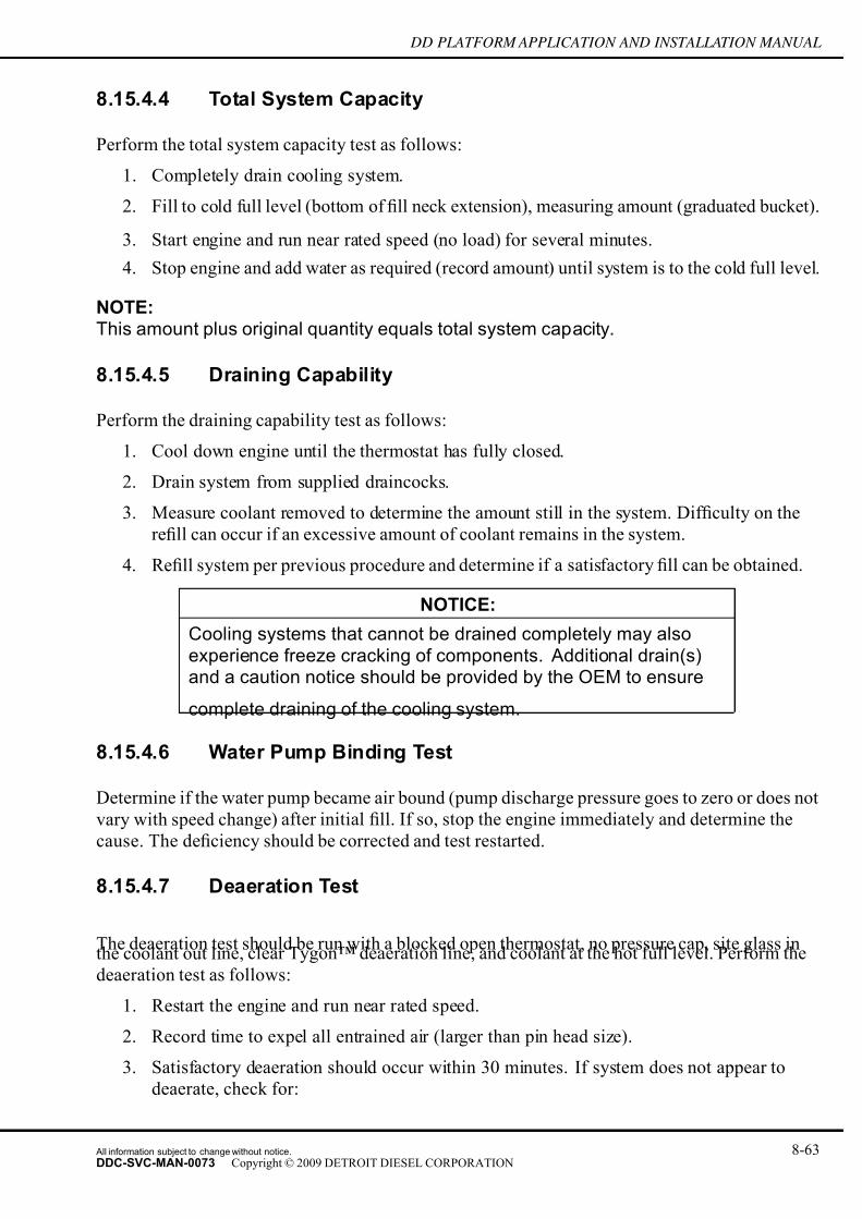
7/14/2019 Dd13-Dd15 a&i Manual
http://slidepdf.com/reader/full/dd13-dd15-ai-manual 161/304
DD PLATFORM APPLICATION AND INSTALLATION MANUAL
8.15.4.4 Total System Capacity
Perform the total system capacity test as follows:
1. Completely drain cooling system.
2. Fill to cold full level (bottom of fill neck extension), measuring amount (graduated bucket).
3. Start engine and run near rated speed (no load) for several minutes.
4. Stop engine and add water as required (record amount) until system is to the cold full level.
NOTE:This amount plus original quantity equals total system capacity.
8.15.4.5 Draining Capability
Perform the draining capability test as follows:
1. Cool down engine until the thermostat has fully closed.
2. Drain system from supplied draincocks.
3. Measure coolant removed to determine the amount still in the system. Dif ficulty on the
refill can occur if an excessive amount of coolant remains in the system.
4. Refill system per previous procedure and determine if a satisfactory fill can be obtained.
NOTICE:
Cooling systems that cannot be drained completely may also
experience freeze cracking of components. Additional drain(s)and a caution notice should be provided by the OEM to ensure
complete draining of the cooling system.
8.15.4.6 Water Pump Binding Test
Determine if the water pump became air bound (pump discharge pressure goes to zero or does not
vary with speed change) after initial fill. If so, stop the engine immediately and determine the
cause. The deficiency should be corrected and test restarted.
8.15.4.7 Deaeration Test
The deaeration test should be run with a blocked open thermostat, no pressure cap, site glass inthe coolant out line, clear Tygon™ deaeration line, and coolant at the hot full level. Perform the
deaeration test as follows:
1. Restart the engine and run near rated speed.
2. Record time to expel all entrained air (larger than pin head size).
3. Satisfactory deaeration should occur within 30 minutes. If system does not appear to
deaerate, check for:
All information subject to change without notice. 8-63DDC-SVC-MAN-0073 Copyright © 2009 DETROIT DIESEL CORPORATION

7/14/2019 Dd13-Dd15 a&i Manual
http://slidepdf.com/reader/full/dd13-dd15-ai-manual 162/304
COOLING SYSTEM, AIR-TO-AIR CHARGE COOLING
□ Coolant agitation in deaeration tank
□ High water pump inlet suction
□ Dirty cooling system or contaminated coolant
□ Exhaust gas leak into coolant
□
Water pump seal air leak Determine the expansion and deaeration volume by adding 8% of the total system capacity on top
of the cold full level. If this amount of coolant cannot be added to the deaeration tank, cold full
level is set too high or the fill neck extension vent hole is not at the top of t he tube. If more than
8% can be added, cold full level could be set higher so more reserve coolant volume is available.
8.15.4.8 Drawdown Test
The drawdown test should be run with a blocked open thermostat, no pressure cap unless coolant
recovery system is used, a site glass in the coolant out line, and coolant at the hot full level.
1. Record the following data while running at rated engine speed (no load speed if ratedcannot be held) and after coolant has been completely deaerated.
□ Engine speed
□ Coolant removed
□ Radiator water flow
□ Water pump discharge pressure
□ Water pump inlet pressure (suction)
□ Engine water out temperature
□ Observations for coolant aeration2. All pressure gages and connecting hoses must be thoroughly bled of air prior to taking
data (engine stopped).
3. Take data with system full and thereafter in 1–quart increments. If system capacity is
above 100 quarts, 2–quart increments are acceptable. Remove water from high pressure
point, preferable water pump discharge.
4. After each incremental draining, check for signs of air in bleed and fill line (transparent)
as well as the radiator (in sight glass). If the bottom of the deaeration tank is not above the
rest of the cooling system, stop the engine at each increment and check for coolant level
equalization. Restart the engine and run again at rated speed. Look for system aeration.
The drawdown rating is determined at the first sign of air. There may not be a loss of flowor pressure at this point. Continue removing water until a significant amount of aeration
occurs or loss of coolant flow (25%-50%) is recorded.
5. Run at maximum tilt angle for installations that operate at severe tilt angles for long
periods of time. The drawdown test has been successfully passed if the amount of coolant
drained is greater than 10% of system capacity or 4 qt. (3.8 L), whichever is greater.
8-64 All information subject to change without notice.
DDC-SVC-MAN-0073 Copyright © 2009 DETROIT DIESEL CORPORATION
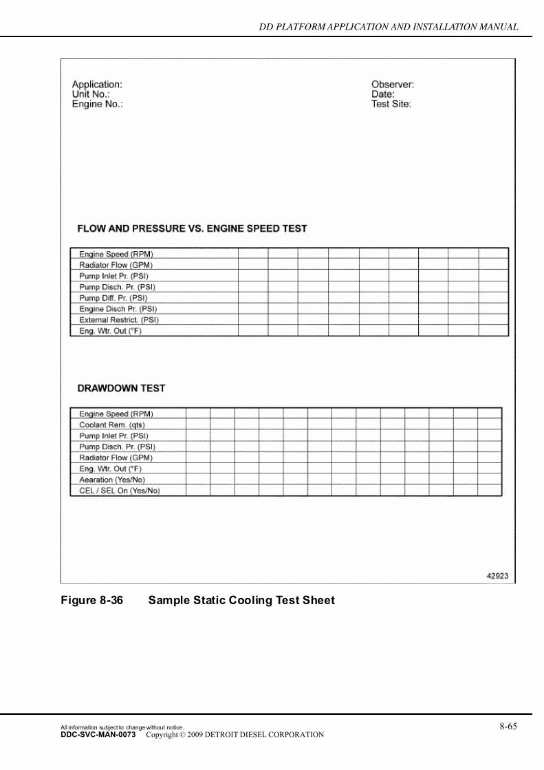
7/14/2019 Dd13-Dd15 a&i Manual
http://slidepdf.com/reader/full/dd13-dd15-ai-manual 163/304
DD PLATFORM APPLICATION AND INSTALLATION MANUAL
Figure 8-36 Sample Static Cooling Test Sheet
All information subject to change without notice. 8-65DDC-SVC-MAN-0073 Copyright © 2009 DETROIT DIESEL CORPORATION

7/14/2019 Dd13-Dd15 a&i Manual
http://slidepdf.com/reader/full/dd13-dd15-ai-manual 164/304
COOLING SYSTEM, AIR-TO-AIR CHARGE COOLING
8.15.4.9 Water Flow and Pressure Test
The coolant flow rate through the engine and/or radiator (heat exchanger) must be wit hin 90% of
the values published on www.detroitdiesel.com to ensure proper cooling. Care must be taken so
coolant shunted away from the engine or radiator to supply cab heaters, air compressors, auxiliary
coolers, wet exhaust systems, etc., are not excessive.
Perform the water flow and pressure test with blocked open thermostats, no pressure cap, below
180°F engine water out. Conduct the test with the system at full level and deaerated.
1. Thoroughly bleed all pressure gages and connecting hoses of air (engine stopped) before
recording the following data.
□ Engine speed, radiator water flow, water pump discharge pressure, water pump inlet
pressure (suction), and engine water out temperature
□ Observations of bleed and fill lines and deaeration tank (flow, flow direction, aeration)
□ Others — depending on application and complexity of the cooling system
2. Start recording data and observations at idle and then in approximately 300-500 rpmincrements up to high no load speed. Be sure data is taken at rated full load speed.
3. Observe fill and bleed line for flow direction, and velocity. Note if deaeration tank coolant
is being agitated causing air to be drawn down fill line. Excessive agitation can be due to
bleed line(s) size or location, size and height of the standpipe(s), vent holes in "doghouse"
inlet(s), or top tank baf fle design. The bleed line(s) should be located low in the deaeration
tank (just above baf fle) if flow is backwards from the top tank to the engine
4. Check water flow and pump inlet pressure at rated engine speed and determine if they
meet the published requirements found on www.detroitdiesel.com, if you do not have
access to www.detroitdiesel.com contact your Distributor.
NOTE:If non-factory-supplied engine water components are used, such as wet exhaust
manifolds, oil coolers, etc., additional flow measurements may be required to ensurecoolant flow through cylinder block and heads has not been seriously reduced. Consult
DDC Application Engineering for assistance.
8.15.4.10 Cooling Index Test
Perform the cooling index test with a blocked open thermostat and the pressure cap installed.
1. Determine the cooling index requirement (ATW) by subtracting the maximum ambient
temperature, other correction (recirculation & radiation), altitude compensation (correctedto sea level — operating altitude x 1°C per 305 m [2°F per 1000 ft.]), and coolant
compensation (3°C [6°F] for 50/50 Ethylene Glycol, 4.4°C (8°F) for 50/50 Proplyene
Glycol, 0°C (0°F) for water), from the maximum allowed coolant out temperature.
2. Calculate the cooling index measurement by subtracting the true ambient temperature and
the altitude compensation, from the coolant out temperature.
3. Start the test with the cooling system at the deaeration cold full level.
8-66 All information subject to change without notice.
DDC-SVC-MAN-0073 Copyright © 2009 DETROIT DIESEL CORPORATION
7/14/2019 Dd13-Dd15 a&i Manual
http://slidepdf.com/reader/full/dd13-dd15-ai-manual 165/304
DD PLATFORM APPLICATION AND INSTALLATION MANUAL
4. Operate the engine at rated speed and full load. The cooling system must be set for
maximum cooling. All heat sources that will affect engine coolant or radiator air
temperatures must be in operation (fans must be in the full on position, shutters locked
full open, appropriate ram air supplied, cab heaters in off position, air conditioner set for
maximum cooling, etc.).
NOTE:Other load points (peak torque, 80% converters ef ficiency, etc.) may be required
depending on the application. This should be determined prior to the test.
5. Various methods of loading the engine to determine cooling index include:
□ Driveline dynamometer
□ Towing dynamometer
□ Chassis dynamometer
□ Steep hill/heavy load
□ In operation load cycle□ Stationary unit
NOTE:
Test results may be dif ficult to interpret if wind conditions exceed 10 miles per hour.
6. Calculate a corrected cooling index.
All information subject to change without notice. 8-67DDC-SVC-MAN-0073 Copyright © 2009 DETROIT DIESEL CORPORATION

7/14/2019 Dd13-Dd15 a&i Manual
http://slidepdf.com/reader/full/dd13-dd15-ai-manual 166/304
COOLING SYSTEM, AIR-TO-AIR CHARGE COOLING
Figure 8-37 Sample Cooling Index Test Sheets
8-68 All information subject to change without notice.
DDC-SVC-MAN-0073 Copyright © 2009 DETROIT DIESEL CORPORATION

7/14/2019 Dd13-Dd15 a&i Manual
http://slidepdf.com/reader/full/dd13-dd15-ai-manual 167/304
DD PLATFORM APPLICATION AND INSTALLATION MANUAL
Figure 8-38 Cooling Index Calculation Sheet
The most effective way to increase cooling capability is by increasing air flow and preventing
hot air recirculation.
All information subject to change without notice. 8-69DDC-SVC-MAN-0073 Copyright © 2009 DETROIT DIESEL CORPORATION

7/14/2019 Dd13-Dd15 a&i Manual
http://slidepdf.com/reader/full/dd13-dd15-ai-manual 168/304
COOLING SYSTEM, AIR-TO-AIR CHARGE COOLING
8.15.5 CHARGE AIR COOLING EVALUATION TEST
The air-to-air charge cooling system must be tested to verify that engine air intake temperatures
and pressure drop limits can be met as shown on www.detroitdiesel.com, if you do not have access
to www.detroitdiesel.com contact your Distributor. This evaluation can be done simultaneously
with the engine cooling index text.
A thorough evaluation will include:
□ Complete description and documentation of the system
□ Adequate instrumentation
□ Proper test preparation
□ Accurate tests
□ Data analysis and documentation
□ Diagnostics (trouble shooting)
□ Corrective action (if necessary)
These tests must be run on all new installations, vehicle r e-powers, or whenever modifications
have been made to the engine, cooling or air-to-air systems as well as changes in load, duty
cycle or environmental operating conditions.
8-70 All information subject to change without notice.
DDC-SVC-MAN-0073 Copyright © 2009 DETROIT DIESEL CORPORATION
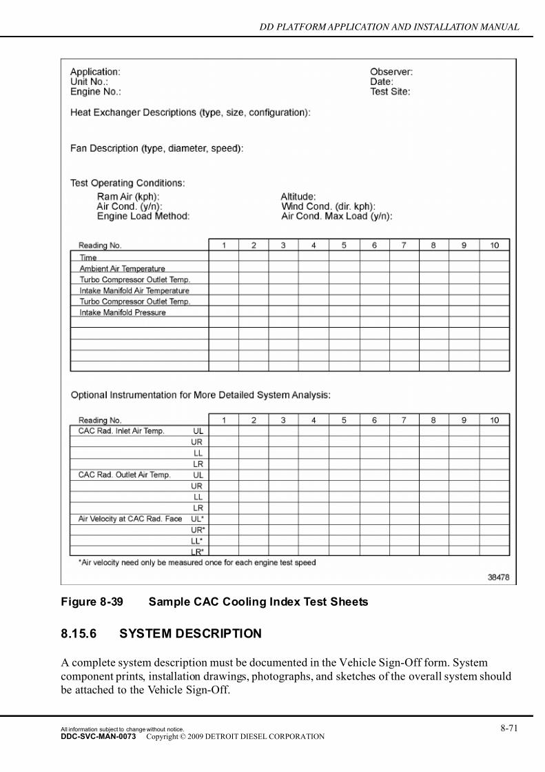
7/14/2019 Dd13-Dd15 a&i Manual
http://slidepdf.com/reader/full/dd13-dd15-ai-manual 169/304
DD PLATFORM APPLICATION AND INSTALLATION MANUAL
Figure 8-39 Sample CAC Cooling Index Test Sheets
8.15.6 SYSTEM DESCRIPTION
A complete system description must be documented in the Vehicle Sign-Off form. System
component prints, installation drawings, photographs, and sketches of the overall system should
be attached to the Vehicle Sign-Off.
All information subject to change without notice. 8-71DDC-SVC-MAN-0073 Copyright © 2009 DETROIT DIESEL CORPORATION

7/14/2019 Dd13-Dd15 a&i Manual
http://slidepdf.com/reader/full/dd13-dd15-ai-manual 170/304
COOLING SYSTEM, AIR-TO-AIR CHARGE COOLING
This information will assist in determining system approval and also be a reference point if
future dif ficulties are encountered.
8.15.7 INSTRUMENTATION
This section describes the instruments and methods needed to measure the temperatures and
pressures of air inlet systems with and without air-to-air charge cooling.
8.15.7.1 Temperature Measurement
Use a precision thermocouple and an appropriate read-out device to measure temperatures.
Thermocouples should be located downstream of the pressure taps.
8.15.7.2 Pressure Measurement
Use a precision gage or a water manometer capable of reading 14 kPa (60 in. H2O) for P.
Use a piezometer ring to measure static pressure in straight pipe sections.
NOTE:
The piezometer ring should be placed within 12.7 cm (5 in.) of the desired measurementlocation.
Figure 8-40 Piezometer Ring
8-72 All information subject to change without notice.
DDC-SVC-MAN-0073 Copyright © 2009 DETROIT DIESEL CORPORATION

7/14/2019 Dd13-Dd15 a&i Manual
http://slidepdf.com/reader/full/dd13-dd15-ai-manual 171/304
DD PLATFORM APPLICATION AND INSTALLATION MANUAL
Figure 8-41 Static Pressure Tap
The instrumentation should be placed perpendicular to the plane of the bend where measurement
on a bend is unavoidable.
All information subject to change without notice. 8-73DDC-SVC-MAN-0073 Copyright © 2009 DETROIT DIESEL CORPORATION
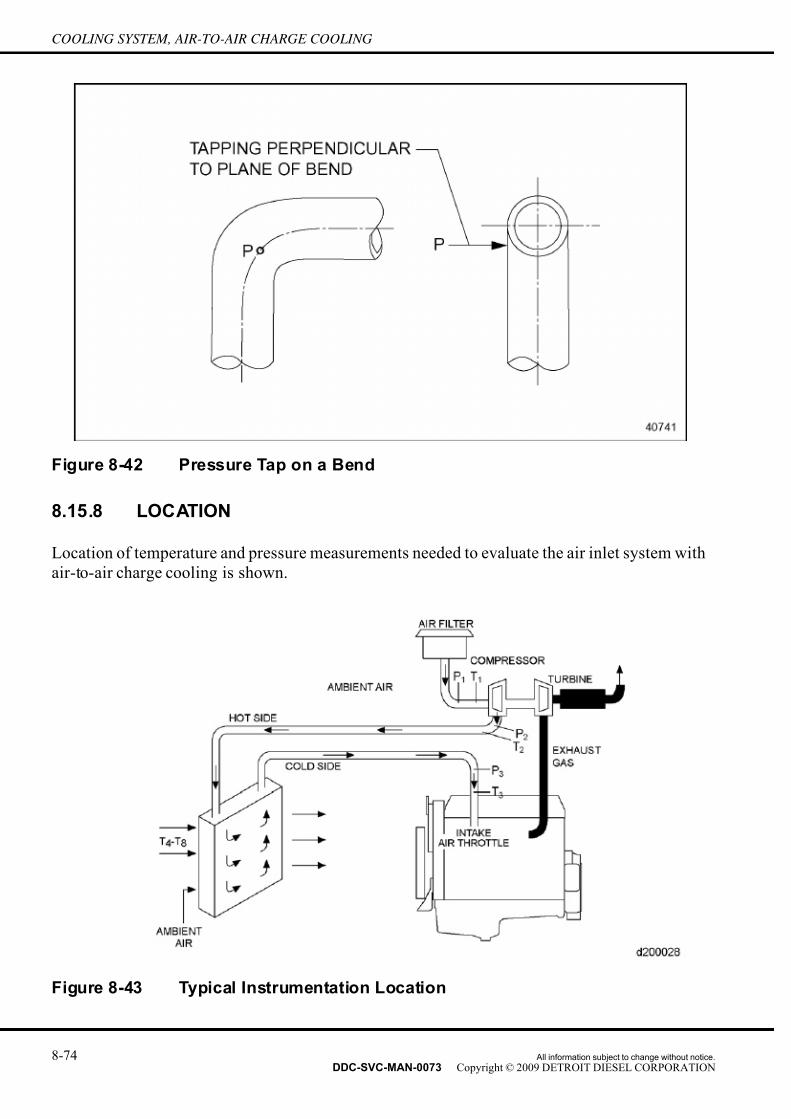
7/14/2019 Dd13-Dd15 a&i Manual
http://slidepdf.com/reader/full/dd13-dd15-ai-manual 172/304
COOLING SYSTEM, AIR-TO-AIR CHARGE COOLING
Figure 8-42 Pressure Tap on a Bend
8.15.8 LOCATION
Location of temperature and pressure measurements needed to evaluate the air inlet system with
air-to-air charge cooling is shown.
Figure 8-43 Typical Instrumentation Location
8-74 All information subject to change without notice.
DDC-SVC-MAN-0073 Copyright © 2009 DETROIT DIESEL CORPORATION
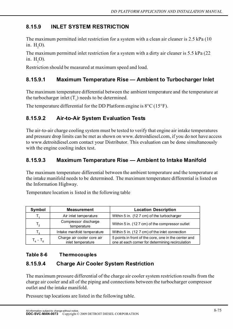
7/14/2019 Dd13-Dd15 a&i Manual
http://slidepdf.com/reader/full/dd13-dd15-ai-manual 173/304
DD PLATFORM APPLICATION AND INSTALLATION MANUAL
8.15.9 INLET SYSTEM RESTRICTION
The maximum permitted inlet restriction for a system with a clean air cleaner is 2.5 k Pa (10
in. H2O).
The maximum permitted inlet restriction for a system with a dirty air cleaner is 5.5 kPa (22
in. H2O).
Restriction should be measured at maximum speed and load.
8.15.9.1 Maximum Temperature Rise — Ambient to Turbocharger Inlet
The maximum temperature differential between the ambient temperature and the temperature at
the turbocharger inlet (T1) needs to be determined.
The temperature differential for the DD Platform engine is 8°C (15°F).
8.15.9.2 Air-to-Air System Evaluation Tests
The air-to-air charge cooling system must be tested to verify that engine air intake temperatures
and pressure drop limits can be met as shown on www.detroitdiesel.com, if you do not have access
to www.detroitdiesel.com contact your Distributor. This evaluation can be done simultaneously
with the engine cooling index test.
8.15.9.3 Maximum Temperature Rise — Ambient to Intake Manifold
The maximum temperature differential between the ambient temperature and the temperature at
the intake manifold needs to be determined. The maximum temperature differential is listed on
the Information Highway.
Temperature location is listed in the following table
Symbol Measurement Location Description
T1
Air inlet temperature Within 5 in. (12 7 cm) of the turbocharger
T2
Compressor discharge
temperatureWithin 5 in. (12 7 cm) of the compressor outlet
T3
Intake manifold temperature Within 5 in. (12 7 cm) of the inlet connection
T4
- T8
Charge air cooler core air
inlet temperature
5 points in front of the core, one in the center and
one at each corner for determining recirculation
Table 8-6 Thermocouples
8.15.9.4 Charge Air Cooler System Restriction
The maximum pressure differential of the charge air cooler system restriction results from the
charge air cooler and all of the piping and connections between the turbocharger compressor
outlet and the intake manifold.
Pressure tap locations are listed in the following table.
All information subject to change without notice. 8-75DDC-SVC-MAN-0073 Copyright © 2009 DETROIT DIESEL CORPORATION

7/14/2019 Dd13-Dd15 a&i Manual
http://slidepdf.com/reader/full/dd13-dd15-ai-manual 174/304
COOLING SYSTEM, AIR-TO-AIR CHARGE COOLING
Symbol Measurement Location Description
P1
Air inlet restrictionWithin 5 in. (12 7 cm) of the turbocharger, in a
straight section after the last bend
P2
Compressor discharge pressureWithin 5 in. (12 7 cm) of the turbocharger, in a
straight section before the first bend
P3
Intake manifold pressure
Within 5 in. (12 7 cm) of the inlet connection in
a straight section after the last bend (or in the
manifold itself)
Table 8-7 Pressure Taps
Connect a precision gage between pressure taps P2
and P3
to determine pressure drop of the
system. Two precision gages may be used as desired.
The maximum pressure drop for DD Platform engines is 10 kPa (39 in. H2O).
8.15.10 TEST
Thorough preparations prior to testing will ensure accurate results.
□ Confirm all instrumentation and equipment is in good working condition and calibrated.
□ Tests must be run on a finalized package installed in unit or vehicle representative of the
production package to be released.
□ Shutters must be fully opened and fan drive mechanisms in the fully engaged position.
□ Confirm that the engine can develop proper load at rated speed using a Diagnostic Data
Reader (DDR) or Detroit Diesel Diagnostic Link®software.
□ Engine should be at normal operation temperature and run at full load.
All air-to-air charge cooling tests should be performed with engine operating at maximum rated
speed and wide open throttle (full fuel). Highway vehicles use either 15 or 30 m.p.h. ram air during testing. Review www.detroitdiesel.com for proper ram air flow conditions for each
installation.
Sample data sheets for air inlet system and charge air cooling system tests are shown.
8.15.11 TEST ANALYSIS
At the completion of the test run, determine the cooling capability of the CAC and whether it
meets requirements.
8.16 COOLING SYSTEM DIAGNOSTICS ANDTROUBLESHOOTING GUIDE
System diagnostics and troubleshooting covers:
□ Engine overheat
□ Cold running engine
8-76 All information subject to change without notice.
DDC-SVC-MAN-0073 Copyright © 2009 DETROIT DIESEL CORPORATION
7/14/2019 Dd13-Dd15 a&i Manual
http://slidepdf.com/reader/full/dd13-dd15-ai-manual 175/304
DD PLATFORM APPLICATION AND INSTALLATION MANUAL
□ Poor cab heater performance
8.16.1 ENGINE OVERHEAT
Coolant temperatures should not exceed maximum limit of 114 °C (237 °F) so metal and oil
temperatures can be controlled for optimum engine performance, fuel economy, and life.
Obvious overheat conditions are determined from the coolant temperature gage, warning, or
shutdown devices. Steam vapor or coolant being expelled through the pressure relief over flow
tube is another indication of overheat. Reduced engine performance or engine oil having a burnt
odor are other indicators.
8.16.1.1 Troubleshooting for Engine Overheat
Troubleshoot for engine overheat as follows:
1. Check for inaccurate gage, warning, or shutdown device, insuf ficient coolant flow, and
inadequate heat transfer capabilities during coolant side investigation.
HOT COOLANT
To avoid scalding from the expulsion of hot coolant, never
remove the cooling system pressure cap while the engine is
at operating temperature. Wear adequate protective clothing(face shield, rubber gloves, apron, and boots). Remove the
cap slowly to relieve pressure.
2. Check that the various temperature monitoring devices are calibrated.
[a] Sensor probes must be located (before thermostat) in a high temperature, well mixed
coolant flow path.
[b] The sensor must be free of scale and other contamination.
3. Check for insuf ficient coolant flow. The following may be causes of insuf ficient coolant
flow:
□ Thermostat — Stuck, sluggish, worn, broken
□ Thermostat seal — Worn, missing, improper installation□ Water pump — Impeller loose or damaged, drive belt loose or missing, worn pulley
□ Aerated coolant — Low coolant level, excessive agitation of deaeration tank coolant,
water pump seal failure, exhaust gas leakage (cracked cylinder head or block,
damaged seals or gaskets, etc.), incorrect bleed line installation
□ Pressurization loss — Defective pressure cap/relief valve or seat, debris trapped
between seats, internal or external leaks anywhere in the system
All information subject to change without notice. 8-77DDC-SVC-MAN-0073 Copyright © 2009 DETROIT DIESEL CORPORATION

7/14/2019 Dd13-Dd15 a&i Manual
http://slidepdf.com/reader/full/dd13-dd15-ai-manual 176/304
COOLING SYSTEM, AIR-TO-AIR CHARGE COOLING
□ High restriction — Radiator plugging (solder bloom), silicate dropout, dirt, debris, etc.
collapsed hose(s), foreign objects in the system (shop towels, plugs, etc.)
□ Core Coolant Flow Capacity — Core coolant flow capacity is often described as “free
flow." This term is used to indicate gravity flow rate through the core and should equal
or exceed the coolant flow rate given on the performance curve. The design of the
radiator inlet and outlet tanks must also offer low restriction to coolant flow.
□ Coolant loss — Internal and external
4. Check for inadequate heat transfer capabilities. The following ar e possible causes of
inadequate heat transfer capabilities:
□ Radiator selection — Core selection inadequate for application
□ Incorrect coolant mixture — Over/under concentration of antifreeze or inhibitors,
corrosive water, incorrect antifreeze or inhibitors
□ Contamination — Oil or other material depositing on heat transfer surfaces
5. Check for insuf ficient air flow. The following are possible causes of insuf ficient air flow:
□ High restriction — Plugged core, damaged or bent fins, shutters not opening correctly,
addition of bug screens, winter fronts, noise panels, small air in or air out openings,
etc.
□ Fan/Drives — Lose or worn belts and pulleys, improper drive engagement, fan
installed backwards or damaged, insuf ficient fan speed (drive ratio), etc.
□ Shroud — Damaged or missing, not completely sealed
□ Fan positioning — Excessive fan tip to shroud clearance, incorrect fan placement in
shroud, insuf ficient fan to core distance, insuf ficient fan to engine distance
6. Check for inadequate heat transfer capabilities. The following are possible causes of
inadequate heat transfer capabilities:
□ Incorrect fan/radiator match — Severest operating conditions not correctly identified.
□ Core degradation — Tube/fin separation, oil film, debris, contamination, etc.
□ Air recirculation — Radiator baf fles damaged or missing, fan shroud and seal damaged
or missing, wind conditions, etc.
7. Also check the following:
□ Increased heat rejection or engine horsepower upgrade
□ Engine, installation, or cooling system modified
□ Increased engine loading, change in duty cycle
□ Running at more adverse conditions than original system design permits, higher
altitude or temperature
8-78 All information subject to change without notice.
DDC-SVC-MAN-0073 Copyright © 2009 DETROIT DIESEL CORPORATION

7/14/2019 Dd13-Dd15 a&i Manual
http://slidepdf.com/reader/full/dd13-dd15-ai-manual 177/304
DD PLATFORM APPLICATION AND INSTALLATION MANUAL
8.16.2 COLD RUNNING ENGINE (OVERCOOLING)
Extended low coolant temperature operation can adversely affect engine performance, fuel
economy, and engine life. Overcooling most frequently occurs at extreme low ambient
temperatures during long idling or low speed and light load operation.
Consider the following for cold running engines:
□ Inaccurate gage, out of calibration, lack of markings to determine actual temperature,
sensor probe in poor location or not fully submerged in a high coolant flow area.
□ Closed thermostat core coolant flow — Top tank baf fle not completely sealed, standpipe too
short or missing, improper sizing of dearation line or standpipe(s) so flow to the top tank
exceeds fill line capacity, over filled cooling system, reverse core flow, thermostat coolant
leakage. See test procedures for determining these deficiencies.
□ Defective thermostat — Stuck open, worn, misaligned, excessive leakage, improper
calibration, incorrect start to open setting.
□ Insuf ficient engine heat rejection — Excessive low speed and load or idle operation, idle
setting too low, over concentration of antifreeze and/or inhibitors, cab and fuel heaters,charge air fan removing heat faster than engine can supply.
□ Fixed fans — Moves air through core when not required.
□ Shutters/Controls — Not fully closed, opening temperature too low.
8.16.3 POOR CAB HEATER PERFORMANCE
Poor cab heater performance results from cold running engines.
Inadequate heat in the operator's environment is symptomatic of poor cab heater performance.
Consider the following to solve poor cab heater performance:
□ Engine coolant temperature below normal.
□ Coolant-side causes
□ Air-side causes
□ Thermostat leakage test
□ Radiator top tank baf fle leakage test
□ Top tank imbalance test
1. Check coolant-side cause, low flow, by investigating the following:
□ Supply and return lines not connected to proper locations on the engine
□ Heater system too restrictive — core, plumbing size, bends, shutoff valves, length of
circuitry, etc.
□ Parallel circuitry with multiple cores
□ Boost pump required, defective, not turned on
All information subject to change without notice. 8-79DDC-SVC-MAN-0073 Copyright © 2009 DETROIT DIESEL CORPORATION

7/14/2019 Dd13-Dd15 a&i Manual
http://slidepdf.com/reader/full/dd13-dd15-ai-manual 178/304
COOLING SYSTEM, AIR-TO-AIR CHARGE COOLING
□ Air in heater circuit and coolant
□ Solder bloom, silicate dropout, dirt, debris, etc.
□ Shutoff valves not fully opened
□ Fuel heater in circuit
2. Check coolant-side cause, reduced heat transfer capabilities, by investigating thefollowing:
□ Improper concentration or grade of antifreeze and inhibitors
□ Undersized heater core(s)
□ Heater plumbing not insulated
□ Low ef ficiency cores
□ Contamination of core tube surfaces, deposits, etc.
□ Fuel heaters plumbed in cab heater circuit
3. Check the following air-side causes:□ Low ef ficiency cores
□ Improper air flow
□ Excess outside air through core
□ Core fins separated from tubes
□ Core surface contamination, dirt, debris, oil film, etc.
□ Leaking air ducts
□ Malfunctioning air flow control valves
□ Undersized heater cores
□ Poor distribution system
Cab interior should be completely sealed to eliminate direct cold air source, in order to conserve
available heat energy. Heat loss to outside can be minimized by using thermo windows, reducing
exposed metal surfaces, increasing insulation usage, etc.
8.16.3.1 Thermostat Leakage Test
The following procedure should be used to determine thermostat leakage:
8-80 All information subject to change without notice.
DDC-SVC-MAN-0073 Copyright © 2009 DETROIT DIESEL CORPORATION

7/14/2019 Dd13-Dd15 a&i Manual
http://slidepdf.com/reader/full/dd13-dd15-ai-manual 179/304
DD PLATFORM APPLICATION AND INSTALLATION MANUAL
NOTICE:
No coolant should leak past the thermostat when the thermostatis closed. Overcooling may occur, resulting in poor engine
performance, poor cab heater performance, or both.
Figure 8-44 Thermostat Leakage Areas
1. Remove radiator inlet hose at the radiator to collect coolant in a container.
All information subject to change without notice. 8-81DDC-SVC-MAN-0073 Copyright © 2009 DETROIT DIESEL CORPORATION

7/14/2019 Dd13-Dd15 a&i Manual
http://slidepdf.com/reader/full/dd13-dd15-ai-manual 180/304
COOLING SYSTEM, AIR-TO-AIR CHARGE COOLING
Figure 8-45 Thermostat Leakage Check
2. Fill system with coolant. If thermostat leakage occurs at this point go to step 4.
3. Start engine and accelerate to high idle and hold for approximately one minute. If leakage
is more than a trickle, continue to step 5.
4. Remove thermostat and visually inspect thermostat for obvious discrepancies. Go to step 6.
5. Calibrate thermostat to ensure it is not opening prematurely.
6. Replace defective parts.
No coolant should leak past the thermostat when the thermostat is closed. Overcooling may occur,
resulting in poor engine performance, poor cab heater performance, or both.
8.16.3.2 CAC Air Leakage Test
The following procedure should be followed to determine if air leakage from a CAC is excessive:
1. Disconnect the charge air cooler.
2. Plug the inlet and outlet.
3. Measure pressure loss using an adaptor plug on the inlet.
The charge air cooler is considered acceptable if it can hold 172 kPa (25 psi) pressure with less
than a 34.5 kPa (5 psi) loss in 15 seconds after turning off the hand valve.
8-82 All information subject to change without notice.
DDC-SVC-MAN-0073 Copyright © 2009 DETROIT DIESEL CORPORATION

7/14/2019 Dd13-Dd15 a&i Manual
http://slidepdf.com/reader/full/dd13-dd15-ai-manual 181/304
DD PLATFORM APPLICATION AND INSTALLATION MANUAL
8.17 MAINTENANCE
The design of the installation must take into account the engine's need for periodic maintenance
and allow access to these service points.
A schedule of periodic maintenance will provide for long term ef ficiency of the cooling system
and extended engine life. Daily visual inspections should be made of t he coolant level and the
overall condition of the system components. This should include looking for obvious leaks and
abnormal distress of the following components:
□ Radiator Core and CAC — Contaminated with oil, dirt and debris; fins/tubes damaged
□ Fill Cap/Neck — Dirty or damaged seats; gasket/seal deteriorated
□ Fan — Blades bent, damaged or missing
□ Belts/Pulleys — Loose belts; frayed; worn; missing
□ Fan Shroud — Loose; broken; missing
□ Hoses/Plumbing — Frayed; damaged; ballooning; collapsing; leaking
□ Coolant — Contaminated, concentration
□ Recirculation Baf fles — Missing; not sealing
If any of the above conditions are observed, corrective action should be taken immediately.
Any time a coolant gage, warning, shutdown, or low level device is malfunctioning, it should
be fixed immediately.
A proper glycol (ethylene, propylene, or extended life organic acid), water, Supplemental Coolant
Additive (SCA) mixture meeting DDC requirements is required for year-round usage.
The coolant provides freeze and boil protection and reduces corrosion, sludge formation, and
cavitation erosion. Antifreeze concentration should not exceed 67% for ethylene glycol (50% for
propylene glycol). Detroit Diesel requir es SCAs be added to all cooling systems at initial fill and
be maintained at the proper concentration. Follow SCA manufacturers' recommendations.
All information subject to change without notice. 8-83DDC-SVC-MAN-0073 Copyright © 2009 DETROIT DIESEL CORPORATION

7/14/2019 Dd13-Dd15 a&i Manual
http://slidepdf.com/reader/full/dd13-dd15-ai-manual 182/304
COOLING SYSTEM, AIR-TO-AIR CHARGE COOLING
THIS PAGE INTENTIONALLY LEFT BLANK
8-84 All information subject to change without notice.
DDC-SVC-MAN-0073 Copyright © 2009 DETROIT DIESEL CORPORATION
7/14/2019 Dd13-Dd15 a&i Manual
http://slidepdf.com/reader/full/dd13-dd15-ai-manual 183/304
DD PLATFORM APPLICATION AND INSTALLATION MANUAL
9 FUEL SYSTEM
Section Page
9.1 FUEL SYSTEM DESCRIPTION .............................................................. 9- 2
9.2 FUEL SYSTEM EQUIPMENT/INSTALLATION GUIDELINES ................ 9- 5
9.3 FUEL SELECTION .................................................................................. 9- 9
All information subject to change without notice. 9-1DDC-SVC-MAN-0073 Copyright © 2009 DETROIT DIESEL CORPORATION

7/14/2019 Dd13-Dd15 a&i Manual
http://slidepdf.com/reader/full/dd13-dd15-ai-manual 184/304
FUEL SYSTEM
9.1 FUEL SYSTEM DESCRIPTION
The purpose of the fuel system is to ensure that the fuel required for combustion is available under
all operating conditions in suf ficient quantity, in the correct sequence, and at the required pressure.
The fuel circuit ensures that the fuel is cleaned before supplying fuel to the fuel injectors.
A fuel system consists of:
□ Fuel Tank
□ Fuel Filter Module with Fuel Prefilter, Water Separator, and Main Filter
□ Water-in-Fuel Sensor
□ Low Pressure Fuel Pump
□ High Pressure Fuel Pump
□ Quantity Control Valve
□ Fuel Rail
□ Fuel Rail Pressure Sensor
□ Pressure Limiting Valve (PLV)
□ Fuel Injectors
□ Fuel Cooler
□ Fuel Doser Valve
□ Hydrocarbon (HC) Doser
□ Fuel Lines
□ Motor Control Module (MCM)
The DD Platform engines employ common rail fuel injection technology. This system works with
a low pressure circuit and an Amplified Pressure Common Rail System (APCRS). The low
pressure circuit delivers fuel to the APCRS. The APCRS delivers fuel to the individual cylinders
through a common rail common to all six fuel injectors.
When the engine is started, the gear driven low pressure fuel pump pulls fuel from the fuel tank
and delivers it to the fuel low pressure circuit. Fuel from the fuel tank is sent through the fuel
filter module. The fuel flows from the fuel filter module to the fuel heat exchanger located on
the Motor Control Module (MCM). The electronic components of the MCM are cooled via the
fuel heat exchanger. The fuel in the fuel filter module first passes into the fuel prefilter where
large particles greater than 100 microns are filtered out. The fuel which has been cleaned by the
fuel prefilter passes out of the fuel filter module to the low pressure fuel pump. From there thefuel is delivered back into the fuel filter module and to the water separator. The water inside the
fuel is separated out by the water separator and begins to fall into the water accumulator. If the
water level in the water accumulator reaches its maximum level, this will be detected by the
Water-in-Fuel sensor. The MCM transmits an appropriate message for illuminating the indicator
lamp. After leaving the water separator, the fuel flows through the final filter. Both the water
separator and final filter elements filter out fine-grained contaminants greater than 2 microns.
9-2 All information subject to change without notice.
DDC-SVC-MAN-0073 Copyright © 2009 DETROIT DIESEL CORPORATION

7/14/2019 Dd13-Dd15 a&i Manual
http://slidepdf.com/reader/full/dd13-dd15-ai-manual 185/304
DD PLATFORM APPLICATION AND INSTALLATION MANUAL
Once all of the contaminants have been filtered out by the final filter, the fuel is delivered out of
the fuel filter module to the quantity control valve of the ACPRS. The quantity contr ol valve is
used to regulate the fuel feed to the high pressure fuel pump and to regulate the fuel rail pressure.
The high pressure fuel pump receives the fuel and pressurizes the fuel up to 900bar. The fuel is
then fed to the fuel rail. Excess fuel from the quantity control valve and high pressure fuel pump
is routed past a 2–stage valve internal to the fuel pump which then routes excess fuel to the fuel
accumulator internal to the fuel filter module. The internal fuel accumulator gathers fuel from allreturn lines and passes it through a bypass valve to either the fuel prefilter or back to the fuel tank.
The fuel that is sent to the fuel rail is regulated by the Fuel Rail Pressure Sensor. If the maximum
rail pressure is exceeded (leakage at 1075 bar, open at 1380 bar), the Pressure Limiting Valve
(PLV) opens and passes the excess fuel through the fuel return lines to the fuel accumulator. If the
system level drops below 3 bar due to the opened PLV, part of the excess fuel is routed to the
high pressure fuel pump for lubrication of the pump. From the fuel rail, fuel is then routed to
each individual fuel injector where the fuel is injected under high pressure into the cylinders. The
excess and warmed fuel from the amplified circuits of each individual injector is routed through a
passage within the cylinder head where it eventually makes its way through the fuel cooler, which
serves to lower the temperature of the fuel to below 100C. From there, the fuel travels into the fuel
filter module where the cooled fuel is mixed with the colder fuel from the low pressure fuel pump.
The Detroit Diesel Electronic Control (DDEC) System controls fuel injection timing and output
by the common rail injectors on the engine. The system also monitors several engine functions
using electrical sensors which send electrical signals to the MCM. The MCM then computes
the incoming data and determines the correct fuel output and timing for optimum power, fuel
economy and emissions.
All information subject to change without notice. 9-3DDC-SVC-MAN-0073 Copyright © 2009 DETROIT DIESEL CORPORATION

7/14/2019 Dd13-Dd15 a&i Manual
http://slidepdf.com/reader/full/dd13-dd15-ai-manual 186/304
FUEL SYSTEM
Figure 9-1 Figure 1-2 Schematic Diagram of the DD Platform Fuel System
9-4 All information subject to change without notice.
DDC-SVC-MAN-0073 Copyright © 2009 DETROIT DIESEL CORPORATION
7/14/2019 Dd13-Dd15 a&i Manual
http://slidepdf.com/reader/full/dd13-dd15-ai-manual 187/304
DD PLATFORM APPLICATION AND INSTALLATION MANUAL
9.2 FUEL SYSTEM EQUIPMENT/INSTALLATIONGUIDELINES
The following installation guidelines cover:
□ Fuel Tank
□ Fuel Filters
□ Fuel Lines
9.2.1 FUEL TANK
Fuel tanks must be made of the correct material, be properly designed and located, and be
adequately sized regardless of the fuel tank configuration being used.
9.2.1.1 Material
Satisfactory fuel tank material is steel, aluminum, or a suitably reinforced plastic. The inside(s)should be clean and free from all impurities likely to contaminate the fuel.
NOTICE:
Do not use a fuel storage tank or lines or fittings made fromgalvanized steel. The fuel will react chemically with the galvanized
coating to form powdery flakes that will quickly clog fuel filters and
cause damage to the fuel pump and injectors
The fuel tank(s) must not be galvanized internally under any circumstances.
The fuel tank(s) or piping may be galvanized or painted on the outside only to prevent rusting.
Zinc in a galvanized coating reacts with sulphur in the fuel to form a white zinc sulfate which
will clog filters as well as damage the fuel pump and injectors.
9.2.1.2 Design
Baf fles must be positioned to separate air from fuel and to prevent fuel from sloshing between the
ends of the tank(s). The baf fles should extend from the top to the bottom of the tank(s). These
baf fles should have passageways which allow the fuel to maintain an even level throughout
the tank(s).
The tank(s) should have a readily accessible drain valve at the bottom for easy removal of contaminants. There should also be an access hole in the tank to permit cleaning when the tank
has been emptied.
The fill neck(s) should be in a clean, accessible location with suf ficient height and room for
an average size fill can or tanker truck hose.
The tanks must have a vent which should be installed at the highest point of the tank. The vent
should be protected so water and dirt cannot enter the system.
All information subject to change without notice. 9-5DDC-SVC-MAN-0073 Copyright © 2009 DETROIT DIESEL CORPORATION
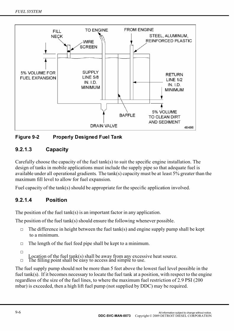
7/14/2019 Dd13-Dd15 a&i Manual
http://slidepdf.com/reader/full/dd13-dd15-ai-manual 188/304
FUEL SYSTEM
Figure 9-2 Properly Designed Fuel Tank
9.2.1.3 Capacity
Carefully choose the capacity of the fuel tank(s) to suit the specific engine installation. The
design of tanks in mobile applications must include the supply pipe so that adequate fuel is
available under all operational gradients. The tank(s) capacity must be at least 5% greater than the
maximum fill level to allow for fuel expansion.
Fuel capacity of the tank(s) should be appropriate for the specific application involved.
9.2.1.4 Position
The position of the fuel tank(s) is an important factor in any application.
The position of the fuel tank(s) should ensure the following whenever possible.
□ The difference in height between the fuel tank(s) and engine supply pump shall be kept
to a minimum.
□ The length of the fuel feed pipe shall be kept to a minimum.
□
Location of the fuel tank(s) shall be away from any excessive heat source.□ The filling point shall be easy to access and simple to use.
The fuel supply pump should not be more than 5 feet above the lowest fuel level possible in the
fuel tank(s). If it becomes necessary to locate the fuel tank at a position, with respect to the engine
regardless of the size of the fuel lines, to where the maximum fuel restriction of 2.9 PSI (200
mbar) is exceeded, then a high lift fuel pump (not supplied by DDC) may be required.
9-6 All information subject to change without notice.
DDC-SVC-MAN-0073 Copyright © 2009 DETROIT DIESEL CORPORATION

7/14/2019 Dd13-Dd15 a&i Manual
http://slidepdf.com/reader/full/dd13-dd15-ai-manual 189/304
DD PLATFORM APPLICATION AND INSTALLATION MANUAL
The fuel tank(s) should not be located higher than the fuel pump. However, when this can not be
avoided, the fuel return line should not extend into the fuel supply to prevent possible siphoning
in the event a leak occurs in the line. The fuel return line must incorporate a check valve. The
fuel inlet must incorporate a shutoff valve of the needle or globe type construction and must
not impose any undue restriction to fuel flow.
Install a shutoff valve for use when changing the fuel pre-filter and the water separator if the fuel
tank(s) is above the fuel filter module. This will prevent the tank(s) from draining.
A check valve in the fuel spill prevents supply side fuel from draining back into the tank(s)
in a tank-below-engine installation.
In applications where multiple tanks are used, a crossover line with valves located near the tanks
low points is recommended to allow equal use of fuel from the tanks. The valves can also be used
to isolate an individual tank in the event that a problem arises with any one tank.
9.2.2 FUEL FILTERS/FUEL FILTER MODULE
A fuel pre-filter, water separator, and a final fuel filter are all required for the DD Platform
engines. These filters are contained within the fuel filter module located between the fuel tank and
the engine low pressure fuel pump. These filters are needed to provide additional water and debris
filtering capacity and to prevent damage to the fuel system. The fuel pre-filter is a 100 micron
rated filter and is an inside out flow filter. The water separator is a 10 micron filter and is an inside
out flow filter. The final fuel filter element is a 3–5 micron rated filter and is an outside in flow
filter. The use of a separate remote mount primary fuel filter, which would typically be installed
between the fuel tank and the engine f uel filter module, are not permitted for use with the DD
Platform engines. However, please contact Detroit Diesel Application Engineering for current
requirements in the event remote mount primary fuel filters become permissible.
9.2.3 FUEL FILTER CONFIGURATION
Fuel filter requirements for the DD Platform engine may be found in DDC publication Lubricating
Oil, Fuel, and Filters, (DDC–SVC–BRO–0001), available on the DDC Extranet.
Care should be taken not to exceed the maximum fuel pump suction limits (2.9 PSI) when
substituting the fuel pre-filter and the water separator elements.
Remote mounting of the fuel filter module filters is not acceptable for the DD Platform engines.
9.2.4 FUEL LINES
The following guidelines apply to supply and return fuel lines between the fuel filter moduleand the tank(s) only.
These guidelines apply regardless of which fuel tank configuration is being used.
Do not modify or tamper with any fuel lines supplied with the engine.
All information subject to change without notice. 9-7DDC-SVC-MAN-0073 Copyright © 2009 DETROIT DIESEL CORPORATION

7/14/2019 Dd13-Dd15 a&i Manual
http://slidepdf.com/reader/full/dd13-dd15-ai-manual 190/304
FUEL SYSTEM
9.2.4.1 Design
All lines should be in protected areas. These areas should be free from possible damage and
securely clipped in position to prevent chaf fing from vibration. Take the necessary precautions to
ensure that the inlet line connections are tight so air cannot enter the fuel system.
The careful selection of line routing cannot be overemphasized. Avoid excessively long runs.
Minimize the number of connections, sharp bends, or other features that could lead to air trapping,
excessive resistance to flow, or waxing of fuel in cold conditions.
The supply and return lines must extend to the low level of useful tank v olume. Extending the
return line to this level prevents siphoning of fuel on the supply side back to the tank.
The fuel supply line must be above the bottom of the tank to ensure that dirt and sediments are not
drawn into the fuel system. Allow 5% clearance volume above the bottom of the tank.
The supply and return lines must be well supported within the tank. Cracks on the supply side can
cause the entrance of air and a subsequent loss of power. The supply and return lines must be
separated by at least 0.3 m (12 in.) inside the tank to prevent the possibility of air or hot fuel from
the return line being discharged directly into the suction line.
The supply line should be at the center of the tank to compensate for angular operation.
Connections of fuel lines to the engine should be made through flexible hoses which accommodate
the movement of the engine and the chassis. Solid tubing cannot be directly connected to the
engine supply or return connections. A minimum of 1 m (3 ft.) of flexible hose should be used
between the engine and chassis fuel lines.
9.2.4.2 Material
DDC does not approve the use of copper tubing because copper becomes brittle due to cold
working when subjected to vibration.
Flexible hosing must be resistant to f uel oil, lubricating oils, mildew, and abrasion, and must be
reinforced.
The lines must withstand a maximum suction of 67.54 kPa (20 in. Hg) without collapsing, a
pressure of 690 kPa (100 psi) without bursting, and temperatures between -40°C (-40°F) and
149°C (300°F).
9.2.4.3 Size
The fuel supply lines should be AN Dash size 10 (5/8” I.D.) or larger. The return lines must beAN Dash size 8 (1/2” I.D.) or larger. Fuel line size on an engine will depend on the engine flow
rate, length of line, number of bends, and the number and type of fittings. Larger fuel line sizes
may be required when the fuel tanks are located farther than 10 ft. (3 m) from the engine or
when there are numerous bends in the system.
The determinant of fuel line size is the restriction measured at the inlet of the fuel pump. The
maximum allowable inlet restriction is 2.9 PSI (200 mbar) for all applications.
9-8 All information subject to change without notice.
DDC-SVC-MAN-0073 Copyright © 2009 DETROIT DIESEL CORPORATION

7/14/2019 Dd13-Dd15 a&i Manual
http://slidepdf.com/reader/full/dd13-dd15-ai-manual 191/304
DD PLATFORM APPLICATION AND INSTALLATION MANUAL
9.3 FUEL SELECTION
The quality of fuel used is a very important factor in obtaining satisfactory engine performance,
long engine life, and acceptable exhaust emission levels. The use of Ultra Low Sulfur Diesel
(ULSD) fuel, sulfur content less than 15 ppm, is required on all DD Platform engines.
For information on fuel selection, refer to DDC publication Lubricating Oil, Fuel, and
Filters(DDC–SVC–BRO–0001).
FIRE
To avoid injury from fire, contain and eliminate leaks of
flammable fluids as they occur. Failure to eliminate leakscould result in fire.
All information subject to change without notice. 9-9DDC-SVC-MAN-0073 Copyright © 2009 DETROIT DIESEL CORPORATION

7/14/2019 Dd13-Dd15 a&i Manual
http://slidepdf.com/reader/full/dd13-dd15-ai-manual 192/304
FUEL SYSTEM
THIS PAGE INTENTIONALLY LEFT BLANK
9-10 All information subject to change without notice.
DDC-SVC-MAN-0073 Copyright © 2009 DETROIT DIESEL CORPORATION

7/14/2019 Dd13-Dd15 a&i Manual
http://slidepdf.com/reader/full/dd13-dd15-ai-manual 193/304
DD PLATFORM APPLICATION AND INSTALLATION MANUAL
10 LUBRICATION SYSTEM
Section Page
10.1 LUBRICATION SYSTEM DESCRIPTION ............................................... 10- 2
10.2 LUBRICATION OIL SELECTION ............................................................ 10- 4
10.3 LUBRICATION FILTER ........................................................................... 10- 4
10.4 ENGINE COMPONENT OIL SUPPLY REQUIREMENTS ...................... 10- 4
10.5 COMPONENT OPTIONS & INSTALLATION REQUIREMENTS ............ 10- 5
10.6 OPERATION AND MAINTENANCE ........................................................ 10- 7
All information subject to change without notice. 10-1DDC-SVC-MAN-0073 Copyright © 2009 DETROIT DIESEL CORPORATION

7/14/2019 Dd13-Dd15 a&i Manual
http://slidepdf.com/reader/full/dd13-dd15-ai-manual 194/304
LUBRICATION SYSTEM
10.1 LUBRICATION SYSTEM DESCRIPTION
The DD Platform engine features a full-flow filtered, pressurized lubricating oil system. The
system incorporates various valves and restriction orifices to optimize the oil flow. The DD
Platform engine comes standard with a thermatic oil cooler, which improves fuel economy in low
oil temperature situations by providing an oil cooler bypass route. A back flow valve retains oil
upstream of the oil pump upon engine shutdown to speed up engine lubrication during start-up. Acrankcase breather is utilized to vent gases from the crankcase. External piping and plumbing is
kept to a minimum to avoid oil leakage. Oil temperature and pressure are monitored by the Motor
Control Module (MCM) for engine protection and diagnostics.
The lubricating system consists of the following components:
□ Oil pump
□ Pressure regulator valve
□ Pressure relief valve
□ Back flow valve
□ Oil filter
□ Oil cooler
□ Oil fill tube
□ Oil level dipstick
□ Oil pan & suction tube
□ Crankcase ventilation breather
□ Oil spray nozzles for each piston
□ Oil pressure sensor □ Oil temperature sensor
10-2 All information subject to change without notice.
DDC-SVC-MAN-0073 Copyright © 2009 DETROIT DIESEL CORPORATION

7/14/2019 Dd13-Dd15 a&i Manual
http://slidepdf.com/reader/full/dd13-dd15-ai-manual 195/304
DD PLATFORM APPLICATION AND INSTALLATION MANUAL
1. Engine Brake 10. Oil Cooler and Housing
2. Turbocharger 11. Oil Filter
3. Axial Power Turbine 12. Oil Refill
4. Crankcase Breather 13. Intake Rocker Arm Spindle Supply
5. Oil Pump 14. Engine Brake Supply
6. Pressure Valve 15. Exhaust Rocker Arm Spindle Supply
7. Backflow Valve 16. Gear Train Oil Supply
8. Suction Pipe 17. Main Bearing Supply
9. Oil Spray Nozzle
Figure 10-1 DD Platform Lubrication System
An internal tooth gear pump is mounted at the rear of the engine block internal to the oil sump
and direct driven by the crankshaft at 1.33 times engine speed. The location of the oil sump
suction tube varies with oil pan choice.
All information subject to change without notice. 10-3DDC-SVC-MAN-0073 Copyright © 2009 DETROIT DIESEL CORPORATION

7/14/2019 Dd13-Dd15 a&i Manual
http://slidepdf.com/reader/full/dd13-dd15-ai-manual 196/304
LUBRICATION SYSTEM
Oil leaving the pump is routed through the back flow valve to the oil cooler and into the oil filter,
then into the main oil gallery in the cylinder block. From there, oil is distributed to the crankshaft,
rods and pistons. Oil spray nozzles exist in the block, which provide a continuous spray of oil
to the underside of the pistons. From the main gallery, oil is routed to the crankcase breather,
turbocharger, through each rocker arm shaft, and into the valve train compone nts, rocker arms,
and engine brakes. Drains from the head, turbocharger, and crankcase breather return oil to the
pan. Oil for gear train components at the rear of the engine is fed through drilled holes out of themain gallery lubricating the gear spindles for each gear drive individually.
There are a variety of options for location of gage and fill, as well as a variety of oil sump
configurations for the DD Platform engine.
10.2 LUBRICATION OIL SELECTION
The DD Platform engine is designed to work with a low ash oil, called API CJ–4. This oil is
uniquely formulated to optimize cleaning intervals of the Diesel Particulate Filter (DPF). For
more information on lubricating oil selection, refer to DDC publication Lubricating Oil, Fuel,
and Filters, (DDC-SVC-BRO-0001).
10.3 LUBRICATION FILTER
The DD Platform engine consists of one full-flow cartridge filter mounted directly to the
oil/coolant module on the left side of the engine. It is not permitted to remote-mount the engine
supplied oil filter.
The micron rating of the oil filters used on the DD Platform engine is given in DDC
publication Lubricating Oil, Fuel, and Filters, (DDC-SVC-BRO-0001), available on the
www.detroitdiesel.com.
Detroit Diesel does not recommend the use of fi berglass-media oil filters such as AC® PF-911Lor equivalent, on the DD Platform engine.
10.3.1 SUPPLEMENTAL FILTRATION SYSTEMS
Bypass oil filters and other after-market supplemental filtration systems are not permitted for
use with the DD Platform engine.
10.4 ENGINE COMPONENT OIL SUPPLY REQUIREMENTS
There are also components mounted externally on the engine which are lubricated by the engine
lubrication system. These are the turbocharger, air compressor, crankcase breather, and customer
supplied components such as alternators, fan clutch, etc.
10-4 All information subject to change without notice.
DDC-SVC-MAN-0073 Copyright © 2009 DETROIT DIESEL CORPORATION

7/14/2019 Dd13-Dd15 a&i Manual
http://slidepdf.com/reader/full/dd13-dd15-ai-manual 197/304
DD PLATFORM APPLICATION AND INSTALLATION MANUAL
10.4.1 TURBOCHARGER LUBRICATION
An oil supply line from the upper right hand side of the engine block supplies oil to the
turbocharger bearing housing. The oil passes through the bearing housing and exits at the bottom,
where an oil drain tube returns the oil to the lower crankcase of the engine block.
10.4.2 AIR COMPRESSOR LUBRICATION
The air compressor receives its oil supply directly from the crankcase through the flange mounted
side of the air compressor. The oil lubricates the compressor crankshaft and rod bearings,
compressor cylinder walls, and then returns the oil to the sump through the crankcase. A separate
oil feed is supplied to the gear spindle.
10.4.3 CRANKCASE BREATHER LUBRICATION
Oil directly from the lower crankcase of the engine block enters into the turbine wheel of the
crankcase breather. Crankcase gases enter the crankcase breather through the top of the unit and
pass through a rotating disc stack driven by the oil lubricated turbine wheel. The rotational
speed of the discs separate the oil particles from the crankcase gases. The gases are vented to
the atmosphere. The resulting oil particles as well as the oil used to drive the turbine wheel
are returned to the oil pan.
10.5 COMPONENT OPTIONS &INSTALLATION REQUIREMENTS
The following component options are available with the following installation requirements
being met.
10.5.1 OIL SAMPLING VALVE
On-Highway customers that perform regular oil sampling tests may request a permanent oil
sampling valve for more convenient service. Detroit Diesel has a provision for an oil sampling
valve to be installed on the DD Platform engine at the oil/coolant module connection. This option
may be specified with the engine and is part of the oil/coolant module group.
10.5.2 OIL CHECKS AND FILLS
Detroit Diesel has a variety of pre-calibrated dipstick and tube assemblies for all oil sump
configurations for DD applications. These parts may be specified with the engine or purchased
separately from the Parts Distribution Center. When the same engine configuration is used in
more than one installation, where the installation angles may vary, it is critical that the proper oil
gage is used for each variant.
All information subject to change without notice. 10-5DDC-SVC-MAN-0073 Copyright © 2009 DETROIT DIESEL CORPORATION

7/14/2019 Dd13-Dd15 a&i Manual
http://slidepdf.com/reader/full/dd13-dd15-ai-manual 198/304
LUBRICATION SYSTEM
Detroit Diesel provides two oil fill options. The standard oil fill location is on the oil/coolant
module. The optional location is on the oil sump. If appropriate check and fill options are not
shown for your particular installation, please contact Detroit Diesel Application Engineering
for new and/or alternative designs.
10.5.3 OIL SUMPS
Various oil sump configurations are available and may be seen on the www.detroitdiesel.com. If
you do not have access to the www.detroitdiesel.com contact your Distributor. For application
guidelines on the use of the various sumps, please contact Detroit Diesel Application Engineering.
10.5.4 ENVIRONMENTALLY SAFE OIL CHANGE (ESOC) FITTINGS
ESOC drain and fill fittings may be specified as part of the engine assembly. These options may
only be used on sumps which include M27 x 2 bulkhead fittings.
When the drain and fill ESOC option is used, a fitting assembly is installed in the front-facing
side of the oil/coolant module. This fitting assembly extends the oil fill connection downwardtowards the oil pan rail. A quick-disconnect fitting and dust cover are provided for the customer
attachment.
The drain fitting used with the ESOC drain and fill option replaces the standard drain plug.
Alternative locations are not recommended, as the fastening of external fittings to the drain
assembly may rotate the tube away from the bottom of the pan.
10.5.5 OIL IMMERSION HEATERS
Oil immersion heaters may be installed in any DD Platform engine oil sump. These heaters should
be installed in a sump port that is constantly submerged in oil. Preferably, the lowest opening inthe side of the pan. Care must be taken in the selection of heaters to ensure they do not interfere
with other components installed in the pan, such as ESOC fittings and the sump pickup. When an
ESOC connection is installed opposite to an oil immersion heater, the element of the heater should
be limited to 140 mm (5.5 in.) in length. Straight heater elements do not present any interference
problems with sump picku ps. To ensure maximum performance and avoid interference problems,
heater elements that bend or curl away from the axis of the installation hole are not recommended.
Oil immersion heaters perform best when energized immediately after engine shutdown, while
the oil is still warm. This practice will minimize the possibility of coking the oil on the heater
element. Elements are most susceptible to oil coking when used on a cold engine. The power
density of the heater element should be kept below 4 Watts per square centimeter, to prevent oil
coking in extreme cold conditions.
10.5.6 OIL LEVEL SENSORS
There will be no oil level sensors available for the DD Platform engine.
10-6 All information subject to change without notice.
DDC-SVC-MAN-0073 Copyright © 2009 DETROIT DIESEL CORPORATION

7/14/2019 Dd13-Dd15 a&i Manual
http://slidepdf.com/reader/full/dd13-dd15-ai-manual 199/304
DD PLATFORM APPLICATION AND INSTALLATION MANUAL
10.6 OPERATION AND MAINTENANCE
The following must be considered for proper operation and maintenance.
10.6.1 FIRST TIME START
DD Platform engines are shipped from the factory with a full oil filter and a minimal amount of oil in the sump. The engine needs to be filled with oil to its high limit previous to a first time
start. The oil level should be verified after the entire engine installation is complete, to avoid false
readings from incorrect angularity during the initial fill.
10.6.2 OIL LEVEL MEASUREMENTS
Oil level should always be checked with the vehicle or apparatus on level ground, and any
ride-height altering controls set to their rest positions. A minimum wait of ten minutes after engine
shutdown is required to achieve an accurate oil level measurement. A twenty minute wait after
shutdown is recommended to allow the oil to fully drain back to the pan from the overhead space.
10.6.3 USED OIL ANALYSIS
Refer to the Technician's Guide Used Lubricating Oil Analysis, DDC-SVC-MAN-0047, for a
detailed procedural description and interpretation of analysis results.
10.6.4 OIL DRAIN INTERVALS
For information on oil drain intervals, refer to DDC publication Lubricating Oil, Fuel, and
Filters, (DDC-SVC-BRO-0001), on the www.detroitdiesel.com.
All information subject to change without notice. 10-7DDC-SVC-MAN-0073 Copyright © 2009 DETROIT DIESEL CORPORATION

7/14/2019 Dd13-Dd15 a&i Manual
http://slidepdf.com/reader/full/dd13-dd15-ai-manual 200/304
LUBRICATION SYSTEM
THIS PAGE INTENTIONALLY LEFT BLANK
10-8 All information subject to change without notice.
DDC-SVC-MAN-0073 Copyright © 2009 DETROIT DIESEL CORPORATION

7/14/2019 Dd13-Dd15 a&i Manual
http://slidepdf.com/reader/full/dd13-dd15-ai-manual 201/304
DD PLATFORM APPLICATION AND INSTALLATION MANUAL
11 ELECTRICAL SYSTEM
Section Page
11.1 ELECTRICAL SYSTEM DESCRIPTION ................................................. 11- 2
11.2 INSTALLATION GUIDELINES ................................................................ 11- 3
All information subject to change without notice. 11-1DDC-SVC-MAN-0073 Copyright © 2009 DETROIT DIESEL CORPORATION

7/14/2019 Dd13-Dd15 a&i Manual
http://slidepdf.com/reader/full/dd13-dd15-ai-manual 202/304
ELECTRICAL SYSTEM
11.1 ELECTRICAL SYSTEM DESCRIPTION
This section describes the function, design, and application of the electrical system for the Detroit
Diesel DD Platform engines.
The purpose of the electrical system is to provide the energy required to start the engine. The
electrical system consists of the following components:
□ Battery charging alternator (Alternator)
□ Voltage regulator (generally integral to the alternator)
□ Storage battery(s)
□ Cranking motor (Starter)
□ Ignition switch
Figure 11-1 Engine Electrical System
11-2 All information subject to change without notice.
DDC-SVC-MAN-0073 Copyright © 2009 DETROIT DIESEL CORPORATION

7/14/2019 Dd13-Dd15 a&i Manual
http://slidepdf.com/reader/full/dd13-dd15-ai-manual 203/304
DD PLATFORM APPLICATION AND INSTALLATION MANUAL
The battery stores electrical energy. The cranking motor converts electrical energy from the
battery into mechanical energy, then transfers the mechanical energy to the engine as a rotational
force. The alternator converts rotational energy from the engine to electrical energy. This
electrical output of the alternator is transferred to the battery where it is stored for later use. The
wiring links the battery to the starter and the alternator to the battery.
The electrical system is activated by means of a master (key) switch. This switch may include a
start position, or a separate start switch may be used. Because the starter solenoid has very highrush current when energized, a magnetic switch is used to carry this current, thereby isolating
the master (key) switch to avoid damage to its switch contacts.
11.2 INSTALLATION GUIDELINES
The engine electrical system with properly matched parts provides a balanced system which
should meet all operating requirements.
11.2.1 BATTERY
The battery is a device for storing electrical energy and converting chemical energy into electrical
energy. Five basic types of batteries are currently available:
□ Filler cap batteries
□ Semi-maintenance free batteries
□ Maintenance-free batteries
□ Deep cycle batteries
□ Gel-cell and nickel cadmium batteries
11.2.1.1 Filler Cap Batteries
Filler cap batteries are lead-acid with a high degree of antimony in the grid alloy. These batteries
require frequent servicing especially adding water and cleaning salts and corrosive deposits
from the terminal posts.
11.2.1.2 Semi-Maintenance Free Batteries
Servicing is reduced with semi-maintenance free batteries due to reduced amount of antimony
in the grid alloy. Water must still be added periodically. Salt and corrosive deposits must be
cleaned from the terminal posts.
11.2.1.3 Maintenance-Free Batteries
Maintenance-free batteries use lead-calcium grid construction without antimony. These batteries
never need water. Ter minal posts do not tend to accumulate salt and corrosive deposits since there
are no filler caps to leak acid fumes, so cable inspection and cleaning are infrequent.
All information subject to change without notice. 11-3DDC-SVC-MAN-0073 Copyright © 2009 DETROIT DIESEL CORPORATION

7/14/2019 Dd13-Dd15 a&i Manual
http://slidepdf.com/reader/full/dd13-dd15-ai-manual 204/304
ELECTRICAL SYSTEM
11.2.1.4 Deep Cycle Batteries
Deep cycle batteries are used for applications like electric drive carts and are not recommended
for engine starting.
11.2.1.5 Gel-Cell And Nickel Cadmium Batteries
Gel-cell and nickel cadmium batteries require charging rates that differ from those used for
lead-acid batteries. The charging rate of DDC supplied alternator s is not compatible with gel-cell
and nickel cadmium batteries. If gel-cell batteries are to be used, consult the battery and alternator
suppliers.
11.2.1.6 Battery Capacity
The minimum battery capacity recommended for accepta ble engine cranking is listed in the
following table.
Minimum Battery Ratings
SAE Cold Cranking Amps @
-17.8°C (0°F)Engine Model System Voltage
Above 0°C (32°F)
DD Platform 12V 1875
Table 11-1 Minimum Battery Capacity for Acceptable Engine Cranking
11.2.1.7 Battery Mounting and Location
Battery mounting boxes, or carriers, support the batteries and protect them from excess vibration,
road splash, saltwater, and other environmental conditions. The battery carrier may be heated or cooled to keep the battery at optimum operating temperature, 27°C (80°F).
The recommended battery carrier designs are:
□ Top crossbar
□ Top mid-frame
□ Top picture frame
□ Angled J-bolt
11-4 All information subject to change without notice.
DDC-SVC-MAN-0073 Copyright © 2009 DETROIT DIESEL CORPORATION
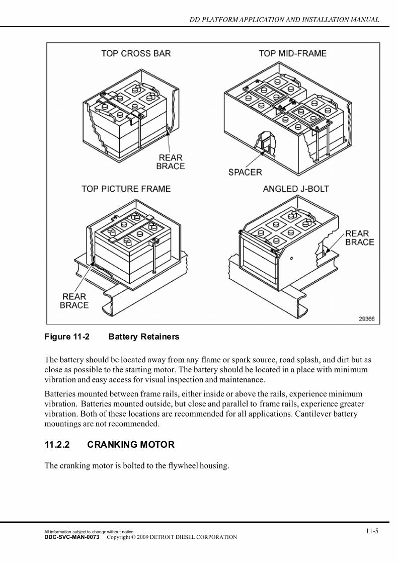
7/14/2019 Dd13-Dd15 a&i Manual
http://slidepdf.com/reader/full/dd13-dd15-ai-manual 205/304
DD PLATFORM APPLICATION AND INSTALLATION MANUAL
Figure 11-2 Battery Retainers
The battery should be located away from any flame or spark source, road splash, and dirt but as
close as possible to the starting motor. The battery should be located in a place with minimum
vibration and easy access for visual inspection and maintenance.
Batteries mounted between frame rails, either inside or above the rails, experience minimum
vibration. Batteries mounted outside, but close and parallel to frame rails, experience greater
vibration. Both of these locations are recommended for all applications. Cantilever battery
mountings are not recommended.
11.2.2 CRANKING MOTOR
The cranking motor is bolted to the flywheel housing.
All information subject to change without notice. 11-5DDC-SVC-MAN-0073 Copyright © 2009 DETROIT DIESEL CORPORATION

7/14/2019 Dd13-Dd15 a&i Manual
http://slidepdf.com/reader/full/dd13-dd15-ai-manual 206/304
ELECTRICAL SYSTEM
NOTICE:
To prevent excessive overrun and damage to the drive andarmature windings, the switch should be opened immediately
when the engine starts. A cranking period should not exceed 30seconds without stopping to allow the motor to cool for at least
two minutes.
Figure 11-3 Cranking Motor Mounting
When the engine start circuit is closed, a drive pinion on the armature shaft engages with the teeth
on the engine flywheel ring gear to crank the engine. When the engine starts, it is necessary to
disengage the drive pinion to prevent the armature from overspeeding and damaging the cranking
motor. To accomplish this, the cranking motor is equipped with an overrunning clutch within the
drive pinion. The cranking motor drive pinion and the enginefl
ywheel ring gear must be matchedto provide positive engagement and to avoid clashing of the gear teeth.
The 39 MT or 42 MT cranking motor typically used on the DD Platform engine has a nose
housing that can be rotated to obtain a number of different solenoid positions with respect to
the mounting flange.
11-6 All information subject to change without notice.
DDC-SVC-MAN-0073 Copyright © 2009 DETROIT DIESEL CORPORATION

7/14/2019 Dd13-Dd15 a&i Manual
http://slidepdf.com/reader/full/dd13-dd15-ai-manual 207/304
DD PLATFORM APPLICATION AND INSTALLATION MANUAL
Figure 11-4 Acceptable Cranking Index with DD Platform
The cranking motor should be installed so that the solenoid is above horizontal.
Mounting the cranking motor with the solenoid above horizontal allows any accumulated moisture
to drain out of the shift housing through the open nose housing. Moisture and condensation may
remain trapped and accumulate in the area of the solenoid and shift linkage and damage the
solenoid if the solenoid is below horizontal.
All information subject to change without notice. 11-7DDC-SVC-MAN-0073 Copyright © 2009 DETROIT DIESEL CORPORATION
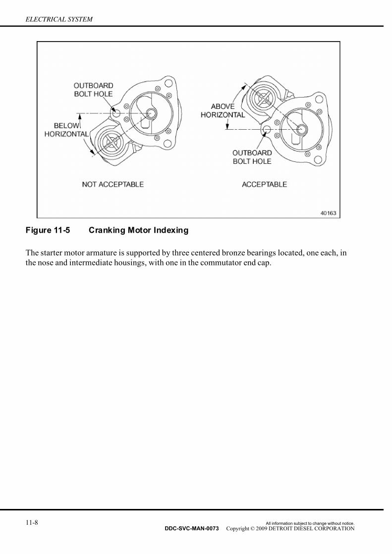
7/14/2019 Dd13-Dd15 a&i Manual
http://slidepdf.com/reader/full/dd13-dd15-ai-manual 208/304
ELECTRICAL SYSTEM
Figure 11-5 Cranking Motor Indexing
The starter motor armature is supported by three centered bronze bearings located, one each, in
the nose and intermediate housings, with one in the commutator end cap.
11-8 All information subject to change without notice.
DDC-SVC-MAN-0073 Copyright © 2009 DETROIT DIESEL CORPORATION
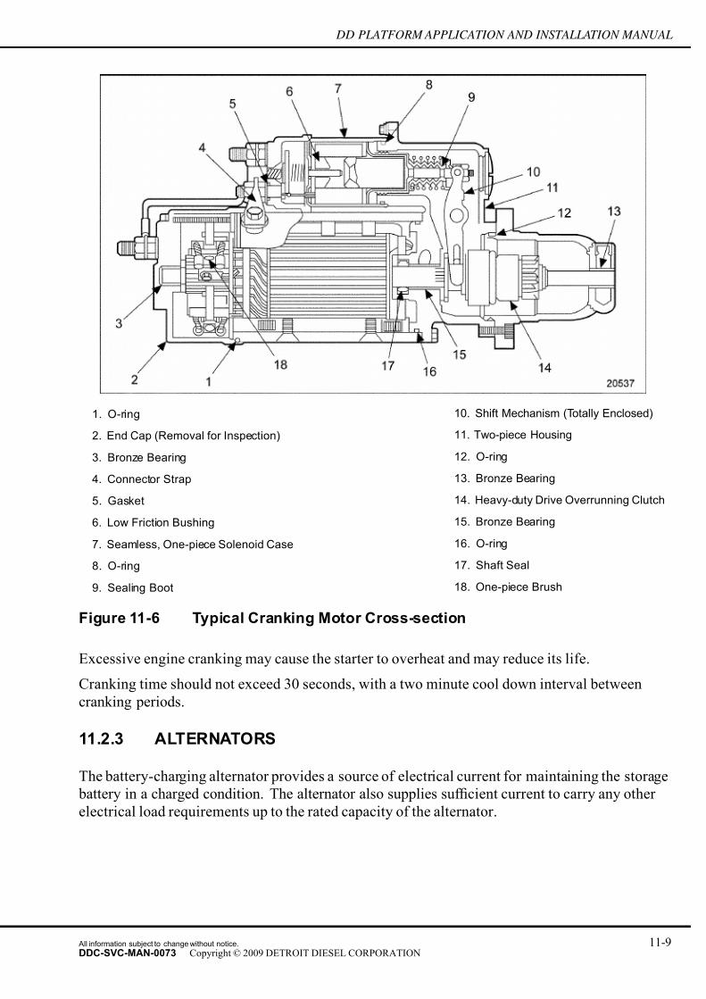
7/14/2019 Dd13-Dd15 a&i Manual
http://slidepdf.com/reader/full/dd13-dd15-ai-manual 209/304
DD PLATFORM APPLICATION AND INSTALLATION MANUAL
1. O-ring 10. Shift Mechanism (Totally Enclosed)
2. End Cap (Removal for Inspection) 11. Two-piece Housing
3. Bronze Bearing 12. O-ring
4. Connector Strap 13. Bronze Bearing
5. Gasket 14. Heavy-duty Drive Overrunning Clutch
6. Low Friction Bushing 15. Bronze Bearing
7. Seamless, One-piece Solenoid Case 16. O-ring
8. O-ring 17. Shaft Seal
9. Sealing Boot 18. One-piece Brush
Figure 11-6 Typical Cranking Motor Cross-section
Excessive engine cranking may cause the starter to overheat and may reduce its life.
Cranking time should not exceed 30 seconds, with a two minute cool down interval between
cranking periods.
11.2.3 ALTERNATORS
The battery-charging alternator provides a source of electrical current for maintaining the storage
battery in a charged condition. The alternator also supplies suf ficient current to carry any other
electrical load requirements up to the rated capacity of the alternator.
All information subject to change without notice. 11-9DDC-SVC-MAN-0073 Copyright © 2009 DETROIT DIESEL CORPORATION
7/14/2019 Dd13-Dd15 a&i Manual
http://slidepdf.com/reader/full/dd13-dd15-ai-manual 210/304
ELECTRICAL SYSTEM
11.2.3.1 Alternator Mounting
The typical mounting assembly includes a mounting bracket that matches the alternator mounting
lugs, an adjusting strap, and associated hardware.
The following guidelines are provided for correct alternator mounting:
NOTICE:
Do not mount the alternator near the exhaust manifold. Mounting
near the exhaust manifold could overheat the alternator and theregulator.
□ A mounting location close to the engine block minimizes mounting bracket overhang.
□ A mounting location not subject to resonant vibration is best.
□ The alternator mounting assembly should support the alternator rigidly so that the alternator
pulley grooves are in the same plane as the driving pulley grooves on the engine. Provision
must be made for belt tension adjustment.□ Drive and driven pulleys must be in parallel and angular alignment to prevent short belt
life or loss of belt.
□ Anchor the adjusting strap and mounting brackets to a rigidly fixed heavy section. Motion
between the mounting bracket and adjusting strap can create an unacceptable vibration.
Incorrect mounting can result in:
□ Improper alignment of pulleys
□ Excessive vibration of mounting assembly components
Improper alignment of pulleys causes excessive belt or pulley wear. Society of Automotive
Engineers' (SAE) recommended practice should be followed with respect to pulley alignment
and tolerances. The pulley groove must be concentric with the bore and the pulley should be
adequately balanced. Fabricated sheet metal pulleys are not recommended for applications with
heavy belt loads. Belt resonance will result in short belt life. Contact the belt manufacturer if
belt resonance is a problem.
Excessive vibration of mounting assembly components can cause failure of the mounting bracket,
the adjusting strap, the alternator mounting lugs, or other alternator components. An effective
bracket must stay firmly attached to the engine.
Under special circumstances, an OEM or distributor may require the mounting location of an
alternator not supplied by DDC. Prior to the manufacturing of the mounting components, the
OEM or distributor must supply details of the design for review. Also a vibration test will be
required. Contact Application Engineering for details.
11-10 All information subject to change without notice.
DDC-SVC-MAN-0073 Copyright © 2009 DETROIT DIESEL CORPORATION

7/14/2019 Dd13-Dd15 a&i Manual
http://slidepdf.com/reader/full/dd13-dd15-ai-manual 211/304
DD PLATFORM APPLICATION AND INSTALLATION MANUAL
11.2.4 GROUNDING REQUIREMENTS
The preferred method of ground return is to use a copper cable from the ground side of the
cranking motor or alternator back to the battery. The cable size should be the same as the supply
cable coming from the battery. When calculating the correct cable size, the distance from the
battery to the cranking motor or alternator as well as the ground return distance must be used
to determine the total cable resistance or system voltage drop.
11.2.5 WIRING
Cables and wiring are an important part of the electrical system which is often overlooked or
neglected.
The cables are the highway on which the electrical energy travels.
Just one faulty or dirty connection can reduce electrical energy transfer just as surely as traf fic
on a modern four lane highway that is narrowed down to one lane. As long as traf fic is light
there is no problem but during rush hour it is quite different. Cranking the engine on a cold
morning with a faulty or dirty connection which restricts the flow is the same as rush hour on asuddenly reduced highway.
11.2.5.1 Guidelines for Electrical Wiring
Guidelines for electrical wiring start with determining the vehicle or chassis type, system voltage,
starting motor type, batteries used, and location. That information is then used to determine
proper routing, cable length and size, insulation, terminals, routing clamps, loom or conduit
requirements and connections.
Use for following guidelines for electrical wiring:
□ Rope stranded copper cable is recommended for #0 or larger cable sizes because of itsadded flexibility.
□ A full copper circuit is recommended for all installations because it maintains the lowest
resistance and is the most trouble free.
□ Good cable routing is not too tight or loose, is properly supported, and avoids excessive
heat, abrasion, and vibration.
□ Conduit or loom should be considered to protect cable where extreme heat or abrasion
cannot be avoided.
□ Die-cast lead alloy terminals are recommended for post-type batteries.
□ Sealed terminals are recommended where sealed terminal batteries are available.
□ Ring terminals are not recommended for battery connections but are recommended for
other connections.
□ Clamps should be used to support the battery cable every 24 in. and to relieve strain at
battery and motor terminals, around corners, and other stress points.
All information subject to change without notice. 11-11DDC-SVC-MAN-0073 Copyright © 2009 DETROIT DIESEL CORPORATION

7/14/2019 Dd13-Dd15 a&i Manual
http://slidepdf.com/reader/full/dd13-dd15-ai-manual 212/304
ELECTRICAL SYSTEM
□ External or internal tooth lock washers are not recommended for battery cable electrical
connections.
□ Frame area where ground connection is made should be stripped of paint and tinned to
prevent corrosion.
□ Recommended battery cable connections to the frame have hardened steel flat washers
with a locking nut.
11.2.5.2 Cable Loss Test Procedure
Correct sizing and installation can be checked by measuring voltages. Once you have the
voltages: Battery Voltage minus Motor Voltage equals Cable Loss.
Measure voltages for correct sizing as follows:
1. Tighten nuts holding battery cables to solenoid and starter terminals.
NOTE:
Solenoid “BAT” terminal is at battery voltage when batteries are connected.
2. Connect the positive carbon pile lead to the starter solenoid “BAT” terminal. Connect the
negative lead to the starter ground terminal.
3. Connect the battery cables within the battery box and tighten to specification.
4. Adjust the load to 500 amps.
5. Quickly measure voltage of a connected battery (measure at a terminal nut or actual post).
6. Turn off load, allow carbon pile to cool.
7. Connect voltmeter to the solenoid “BAT” terminal and starter ground. Connect directly
to terminals, not to load clamp.8. Adjust load to 500 amps.
9. Measure motor voltage.
10. Turn off load.
11.2.5.3 Measuring Circuit Resistance
To measure cranking circuit resistance, disconnect positive and negative cables at the battery.
Install a galvanometer or precision ohmmeter (0.0001 ohms resolution) and read the resistance.
Resistance should be less than the maximum allowable for this system. If the measurement
exceeds the maximum values, corrective measures such as cleaning the connections, reducing the
number of connections, or increasing wire gage will have to be taken.
11-12 All information subject to change without notice.
DDC-SVC-MAN-0073 Copyright © 2009 DETROIT DIESEL CORPORATION

7/14/2019 Dd13-Dd15 a&i Manual
http://slidepdf.com/reader/full/dd13-dd15-ai-manual 213/304
DD PLATFORM APPLICATION AND INSTALLATION MANUAL
Figure 11-7 Cable Resistance
11.2.5.4 Calculating Circuit Resistance
If a galvanometer is not available, circuit resistance may be estimated as follows:
1. Measure the total length of the cable from the battery to the starter and back to the battery.
2. Use the chart to estimate cable resistance.
3. Count the number of connections in circuit.
4. Multiply the number of connections by 0.00001 ohms.
5. Add this number to the cable resistance number found in step 4. Also add 0.0002 ohms for
any contacts in the circuit.
6. If this total resistance exceeds the value listed in the following table, corrective action
must be taken.
All information subject to change without notice. 11-13DDC-SVC-MAN-0073 Copyright © 2009 DETROIT DIESEL CORPORATION

7/14/2019 Dd13-Dd15 a&i Manual
http://slidepdf.com/reader/full/dd13-dd15-ai-manual 214/304
ELECTRICAL SYSTEM
Magnetic Switch and Series-Parallel Circuit Circuit Resistance
12 V system 0.048 ohms
Solenoid Switch Circuit
12 V system 0.0067 ohms
Starting Motor Circuit
12 V system 0.0012 ohms
12 V high output system 0.00075 ohms
Table 11-2 Maximum Circuit Resistance
11-14 All information subject to change without notice.
DDC-SVC-MAN-0073 Copyright © 2009 DETROIT DIESEL CORPORATION
7/14/2019 Dd13-Dd15 a&i Manual
http://slidepdf.com/reader/full/dd13-dd15-ai-manual 215/304
DD PLATFORM APPLICATION AND INSTALLATION MANUAL
12 MOUNTING SYSTEM
Section Page
12.1 MOUNTING SYSTEM DESCRIPTION ................................................... 12- 2
12.2 SOLID MOUNTING SYSTEMS ............................................................... 12- 3
12.3 FLEXIBLE MOUNTING SYSTEMS ......................................................... 12- 4
12.4 INSTALLATION CHECK LIST ................................................................. 12- 6
12.5 ENGINE SUPPORT ................................................................................ 12- 7
All information subject to change without notice. 12-1DDC-SVC-MAN-0073 Copyright © 2009 DETROIT DIESEL CORPORATION

7/14/2019 Dd13-Dd15 a&i Manual
http://slidepdf.com/reader/full/dd13-dd15-ai-manual 216/304
MOUNTING SYSTEM
12.1 MOUNTING SYSTEM DESCRIPTION
The purpose of the engine mounting system is to isolate engine vibrations from the supporting
structure. This section describes the functions, design, and application for the mounting system
of a DD Platform engine.
The major functional requirements of an engine mounting system are:
□ To control and reduce the engine motion
□ To isolate engine vibrations from the structure
□ To control external forces during shock or transient conditions to prevent physical contact
between the engine and the application
□ To limit the bending moments at the cylinder block-to-flywheel housing within the
maximum values specified for the engine and application
Flexible mounts, solid mounts, or a combination of the two types of mounts represent the different
mounting system configurations. Flexible mountings enable the supporting structure to be
isolated from engine vibration. Solid mountings are used when the movement of an engine withflexible mounts is not acceptable. Solid mountings are also used in applications where shock,
torque, and thrust loads exceed the limits of resilient flexible mounts. A combination of solid
and flexible mountings may be used based on the relationship required between the engine and
the machine. The vibration characteristics of the total installation will depend on the combined
weight of the engine, accessories, and interface equipment, the rigidity of the mounting system
and the structure where it sits. Most mount manufacturers have computer analysis programs
which determine the proper mounts for specific applications.
12.1.1 THREE-POINT MOUNTING
Three-point mounting is based on the principle that three points define a plane and thereforeengine block and driven machinery twisting will not occur. Three point mounting is required for
off highway and rough terrain mobile applications, but it can also readily be used in stationary
applications. It is accomplished with one mounting point at the front and two at the rear. The
front mount provides support vertically and transversely but will not restrain torsionally. For
torsional support a bracket is attached to each side of the flywheel housing, with the driven
mechanism flange mounted to the engine.
Care must be taken to ensure that the mounting points are located in a way such that the bending
moment at the rear face of the block is less than 1000 lb·ft.
12-2 All information subject to change without notice.
DDC-SVC-MAN-0073 Copyright © 2009 DETROIT DIESEL CORPORATION

7/14/2019 Dd13-Dd15 a&i Manual
http://slidepdf.com/reader/full/dd13-dd15-ai-manual 217/304
DD PLATFORM APPLICATION AND INSTALLATION MANUAL
Figure 12-1 General Three Point Mounting Scheme
NOTE:The engine must be analyzed for the bending moment produced at the rear face of the
block. If the bending moment exceeds the limit of 1,356 N·m (1,000 ft·lb), then the rear mounts must be located to achieve a bending moment within these limits, ideally as
close to zero as possible.
The rear mounts should restrain motion in all six degrees of freedom and provide the necessary
torque reaction forces. Isolation mounts can be used under both front and rear mounting bracketsif applicable.
12.2 SOLID MOUNTING SYSTEMS
Solid mounting is used in applications where severely high shock, torque and/or thrust loads
are introduced. Solid mounts are, therefore, used in instances where flexible mounting is not
acceptable due to the physical conditions which will be encountered for the given application.
In any solid mounting arrangement, consider the following :
□ Make the mounting brackets and mounting base as rigid as possible.
□ Alignment of the engine and the machine being driven must be carefully controlled tominimize loading on the coupling, flywheel, and flywheel housing. If the assembly is
remote mounted and shaft driven with a coupling, check for face run out to 0.002 in.
(0.051 mm) on each flange apart. With flanges together a 0.127 mm. (0.005 in) gap is
permitted for angular misalignment. Concentricity, also checked with dial indicators,
should be good within 0.127 mm. (0.005 in). (Make adjustments by shimming under
one or more of the solid mounts.
All information subject to change without notice. 12-3DDC-SVC-MAN-0073 Copyright © 2009 DETROIT DIESEL CORPORATION
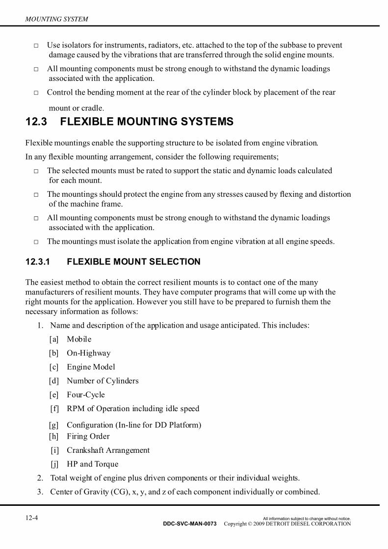
7/14/2019 Dd13-Dd15 a&i Manual
http://slidepdf.com/reader/full/dd13-dd15-ai-manual 218/304
MOUNTING SYSTEM
□ Use isolators for instruments, radiators, etc. attached to the top of the subbase to prevent
damage caused by the vibrations that are transferred through the solid engine mounts.
□ All mounting components must be strong enough to withstand the dynamic loadings
associated with the application.
□ Control the bending moment at the rear of the cylinder block by placement of the rear
mount or cradle.
12.3 FLEXIBLE MOUNTING SYSTEMS
Flexible mountings enable the supporting structure to be isolated from engine vibration.
In any flexible mounting arrangement, consider the following requirements;
□ The selected mounts must be rated to support the static and dynamic loads calculated
for each mount.
□ The mountings should protect the engine from any str esses caused by flexing and distortion
of the machine frame.
□ All mounting components must be strong enough to withstand the dynamic loadings
associated with the application.
□ The mountings must isolate the application from engine vibration at all engine speeds.
12.3.1 FLEXIBLE MOUNT SELECTION
The easiest method to obtain the correct resilient mounts is to contact one of the many
manufacturers of resilient mounts. They have computer programs that will come up with the
right mounts for the application. However you still have to be prepared to furnish them the
necessary information as follows:
1. Name and description of the application and usage anticipated. This includes:
[a] Mobile
[b] On-Highway
[c] Engine Model
[d] Number of Cylinders
[e] Four-Cycle
[f] RPM of Operation including idle speed
[g] Configuration (In-line for DD Platform)
[h] Firing Order
[i] Crankshaft Arrangement
[j] HP and Torque
2. Total weight of engine plus driven components or their individual weights.
3. Center of Gravity (CG), x, y, and z of each component individually or combined.
12-4 All information subject to change without notice.
DDC-SVC-MAN-0073 Copyright © 2009 DETROIT DIESEL CORPORATION

7/14/2019 Dd13-Dd15 a&i Manual
http://slidepdf.com/reader/full/dd13-dd15-ai-manual 219/304
DD PLATFORM APPLICATION AND INSTALLATION MANUAL
4. Moments of inertia Ixx, Iyy, Izz about the CG if known. Otherwise, a dimensional
drawing of the engine is needed to make an estimate.
5. Mounting pad positions x, y, and z relative to RFOB and crankshaft centerline.
6. Desired amount of isolation if known, usually a minimum of 90%, and 96-98% for
generators in buildings.
7. Any expected shock or impact loads described in g's and direction.
8. Closest point x, y, z and clearances to machine members.
9. Any external forces, such as belt and chain drives, their direction and position.
10. Any environmental conditions such as temperature highs and lows, chemical or oil
exposures, etc.
For common, non shock load applications the general procedure for self selection of mounts
has two possible methods:
□ Method A: Select a type of mount that supports the load from the supplier catalog and then
calculate its isolation capability.
□ Method B: Specify the isolation desired and calculate the mount characteristics required to
obtain this. Then select the mount from the catalog.
For more details and formulas to use in your calculations, refer to Barry Controls bulletin IOEM1,
or Lord Manufacturing bulletin PC2201o. The suitability of the selected mounts should still
be confirmed with the manufacturer. Detroit Diesel assumes no responsibility for the resilient
mounting system performance.
12.3.1.1 Method A
Select a type of mount that supports the load from the supplier catalog.1. Determine the location of CG of the engine and transmission package.
2. Calculate the reaction forces at each mount using the weight and CG. Some mount
manufacturers include safety factors up to three times the mount load rating, to allow for
forces due to engine torque and rugged terrain, so weight only is normally suf ficient to use
for this calculation. However, if the power package will be subject to low gear, high torque
operation, then the force due to torque must be added. Consult the manufacturer to be sure.
3. Refer to the mount tables in the catalog that suits the application and the environmental
conditions. There might be more than one suitable table to refer to.
4. From your table of choice, select a mount that is within the load range. There might
be several mount models to choose from.
5. Using constant f or stiffness (K) from the table or accompanying load vs. deflection
charts, and the weight (W) at the mounting point, calculate the natural frequency (Fn.)
of that mount.
All information subject to change without notice. 12-5DDC-SVC-MAN-0073 Copyright © 2009 DETROIT DIESEL CORPORATION

7/14/2019 Dd13-Dd15 a&i Manual
http://slidepdf.com/reader/full/dd13-dd15-ai-manual 220/304
MOUNTING SYSTEM
6. Determine what are the prominent disturbing frequencies (Fi) of the input source. It
usually consists of the engine first order or other known disturbing orders, or it could be
the bumpy terrain. If the engine speed varies, use the lowest speed setting as well as the
normal steady running speed. Calculate Fi/Fn. If it is greater than the mount system is
in the isolation range. If it is less than it is in the amplification range and may not be
suitable. If it is close to 1.0, it is close to resonance and should not be used at all.
Figure 12-2 Transmissibility
12.3.1.2 Method B
Specify the isolation desired and calculate the mount characteristics required then select the
mount from the catalog.
1. Establish a desired isolation requirement (I). 80% isolation ef ficiency or 0.8 is acceptable.
2. Determine transmissibility (T). T = 1.0 – I. In this case, T = 1.0 – 0.8 = 0.2
3. Determine Fn by the following formula:
4. With this Fn determine spring rate needed (K) from the formula where M
= W/g, W/g = weight at the mount point/gravitational constant.
5. Refer to the catalog for the desired mount that has that spring rate, or close to it. Recheck
its suitability by repeating the steps in Method A.
12.4 INSTALLATION CHECK LIST
To ensure proper installation of the isolators, DDC has found several common problems to check
for upon completion. The most important items are:
12-6 All information subject to change without notice.
DDC-SVC-MAN-0073 Copyright © 2009 DETROIT DIESEL CORPORATION

7/14/2019 Dd13-Dd15 a&i Manual
http://slidepdf.com/reader/full/dd13-dd15-ai-manual 221/304
DD PLATFORM APPLICATION AND INSTALLATION MANUAL
1. Based on the engine support calculation, ensure that the load capacity of the isolator is
adequate at each location.
2. When applicable, ensure that the space between the mount and structure is enough to
prevent "shorting" of the isolator.
3. Ensure that there are no sound-shorts: direct contact of the engine with other components
(brackets, pipes, etc.) which are rigidly attached to the frame/applications.4. For mounting systems other than three-point the load at each mount should be balanced or
adjusted to prevent excessive loads at the mountings and high e ngine vibration levels.
12.5 ENGINE SUPPORT
To determine the distance of rear mounts to achieve a zero bending moment at the rear of the
cylinder block. The following information must be filled out.
All information subject to change without notice. 12-7DDC-SVC-MAN-0073 Copyright © 2009 DETROIT DIESEL CORPORATION
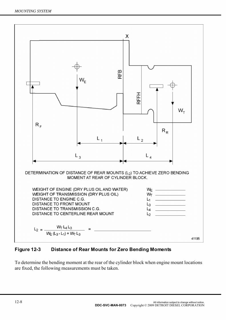
7/14/2019 Dd13-Dd15 a&i Manual
http://slidepdf.com/reader/full/dd13-dd15-ai-manual 222/304
MOUNTING SYSTEM
Figure 12-3 Distance of Rear Mounts for Zero Bending Moments
To determine the bending moment at the rear of the cylinder block when engine mount locations
are fixed, the following measurements must be taken.
12-8 All information subject to change without notice.
DDC-SVC-MAN-0073 Copyright © 2009 DETROIT DIESEL CORPORATION

7/14/2019 Dd13-Dd15 a&i Manual
http://slidepdf.com/reader/full/dd13-dd15-ai-manual 223/304
DD PLATFORM APPLICATION AND INSTALLATION MANUAL
Figure 12-4 Bending Moment for Fixed Mounting System
All information subject to change without notice. 12-9DDC-SVC-MAN-0073 Copyright © 2009 DETROIT DIESEL CORPORATION

7/14/2019 Dd13-Dd15 a&i Manual
http://slidepdf.com/reader/full/dd13-dd15-ai-manual 224/304
MOUNTING SYSTEM
THIS PAGE INTENTIONALLY LEFT BLANK
12-10 All information subject to change without notice.
DDC-SVC-MAN-0073 Copyright © 2009 DETROIT DIESEL CORPORATION

7/14/2019 Dd13-Dd15 a&i Manual
http://slidepdf.com/reader/full/dd13-dd15-ai-manual 225/304
DD PLATFORM APPLICATION AND INSTALLATION MANUAL
13 TORSIONAL ANALYSIS
Section Page
13.1 TORSIONAL ANALYSIS DESCRIPTION ................................................ 13- 2
13.2 MASS ELASTIC DATA ............................................................................ 13- 2
13.3 TORSIONAL ANALYSIS REQUEST FORM ........................................... 13- 6
All information subject to change without notice. 13-1DDC-SVC-MAN-0073 Copyright © 2009 DETROIT DIESEL CORPORATION

7/14/2019 Dd13-Dd15 a&i Manual
http://slidepdf.com/reader/full/dd13-dd15-ai-manual 226/304
TORSIONAL ANALYSIS
13.1 TORSIONAL ANALYSIS DESCRIPTION
A Torsional Vibration Analysis (TVA) is required for all applications. If an installation is identical
(same engine power and torque ratings, crankshaft pulley, damper, flywheel, rotational devices
connected to the engine and same types of connection hardware to drive the rotational devices) to
an application that was previously analyzed, then the previously a pproved TVA can be applied.
DDC will perform the only acceptable Torsional Vibration Analysis for the engine. Other
organizations also perform TVAs; however, the results obtained from other organizations will
not be accepted for the evaluation of stresses occurring in the crankshaft. Typically, the analysis
completed by the other organizations will suf ficiently define mode shapes, system natural
frequencies, and amplitudes or velocities. DDC will not accept these analyses as approval for
the engine for any application. The only acceptable evaluation of the stresses occurring in the
crankshaft is the analysis completed by DDC.
Torsional analysis request (TAR) forms are included in this manual for use in submitting requests
to DDC. In order to minimize the turn around time of th e analysis, only forms completed in their
entirety should be submitted. For additional information regarding this topic, please refer to the
Noise, Vibration, Harshness (NVH) Portal available through the DDC www.detroitdiesel.com or contact your application engineer.
13.2 MASS ELASTIC DATA
Mass elastic system data consists of inertias, torsional stiffness, and minimum shaft polar section
modules for all rotating components (excluding belt driven components such as fans, pumps,
compressors, etc.). Equivalent mass elastic systems of a DD Platform engine are provided on
the following pages. These figures represent typical mass elastics without crankshaft pulleys,
vibration dampers or flywheels. The specific information regarding optional equipment can be
obtained by contacting: Nicole Bond (+1 313 592 5872), Torsional Vibration Analyst
13-2 All information subject to change without notice.
DDC-SVC-MAN-0073 Copyright © 2009 DETROIT DIESEL CORPORATION

7/14/2019 Dd13-Dd15 a&i Manual
http://slidepdf.com/reader/full/dd13-dd15-ai-manual 227/304
DD PLATFORM APPLICATION AND INSTALLATION MANUAL
Figure 13-1 Mass Elastic Data
All information subject to change without notice. 13-3DDC-SVC-MAN-0073 Copyright © 2009 DETROIT DIESEL CORPORATION

7/14/2019 Dd13-Dd15 a&i Manual
http://slidepdf.com/reader/full/dd13-dd15-ai-manual 228/304
TORSIONAL ANALYSIS
Figure 13-2 Mass Elastic Data Page 1 of 3
13-4 All information subject to change without notice.
DDC-SVC-MAN-0073 Copyright © 2009 DETROIT DIESEL CORPORATION

7/14/2019 Dd13-Dd15 a&i Manual
http://slidepdf.com/reader/full/dd13-dd15-ai-manual 229/304
DD PLATFORM APPLICATION AND INSTALLATION MANUAL
Figure 13-3 Mass Elastic Data Page 2 of 3
All information subject to change without notice. 13-5DDC-SVC-MAN-0073 Copyright © 2009 DETROIT DIESEL CORPORATION

7/14/2019 Dd13-Dd15 a&i Manual
http://slidepdf.com/reader/full/dd13-dd15-ai-manual 230/304
TORSIONAL ANALYSIS
13.3 TORSIONAL ANALYSIS REQUEST FORM
Figure 13-4 Torsional Analysis Request Form
13-6 All information subject to change without notice.
DDC-SVC-MAN-0073 Copyright © 2009 DETROIT DIESEL CORPORATION
7/14/2019 Dd13-Dd15 a&i Manual
http://slidepdf.com/reader/full/dd13-dd15-ai-manual 231/304
DD PLATFORM APPLICATION AND INSTALLATION MANUAL
14 ENGINE ELECTRONIC CONTROLS
Section Page
14.1 ENGINE ELECTRONIC CONTROLS DESCRIPTION ............................ 14- 2
14.2 ORIGINAL EQUIPMENT MANUFACTURER INSTALLATION REQUIRE-
MENTS .................................................................................................... 14- 2
14.3 MOTOR CONTROL MODULE ................................................................ 14- 3
14.4 COMMON POWERTRAIN CONTROLLER ............................................. 14- 3
14.5 ELECTRONIC FUEL INJECTOR ............................................................ 14- 4
14.6 WIRING HARNESSES ............................................................................ 14- 5
14.7 SYSTEM SENSORS ............................................................................... 14- 8
14.8 WELDING ............................................................................................... 14-11
All information subject to change without notice. 14-1DDC-SVC-MAN-0073 Copyright © 2009 DETROIT DIESEL CORPORATION

7/14/2019 Dd13-Dd15 a&i Manual
http://slidepdf.com/reader/full/dd13-dd15-ai-manual 232/304
ENGINE ELECTRONIC CONTROLS
14.1 ENGINE ELECTRONIC CONTROLS DESCRIPTION
The Detroit Diesel Electronic Control System (DDEC) is an electronic fuel injection and control
system. The system optimizes control of critical engine functions which affect fuel economy,
performance, and emissions. The DDEC system provides the capability to protect the engine from
serious damage resulting from conditions such as high engine temperatures or low oil pressure.
The major subsystems of DDEC include:
□ Motor Control Module (MCM)
□ Common Powertrain Controller (CPC)
□ Electronic Injectors
□ System Sensors
The MCM receives electronic inputs from sensors on the engine and vehicle and uses the
information to control engine operation. The MCM computes fuel timing and fuel quantity based
upon predetermined calibration tables in its memory. The MCM precisely times and meters
fuel to each injector.Detroit Diesel Diagnostic Link® (DDDL), a sophisticated software package supporting the set
up, maintenance and repair of engines using DDEC, facilitates access to DDEC's diagnostic
capabilities. Used as a diagnostic tool DDDL can be used to change the engine rating, view an
audit trail of CPC changes, monitor fault codes as they occur, snapshot recording, set the MCM
output functions to particular values to support troubleshooting, and configure and change CPC
parameter values.
DDEC VI provides one industry standard serial data link: SAE Standard J1939. SAE Standard
J1939 provides control data to other vehicle systems such as transmissions and ABS control
devices. High-speed CAN link is also used for transmittals between the CPC and MCM modules.
14.2 ORIGINAL EQUIPMENT MANUFACTURERINSTALLATION REQUIREMENTS
Original Equipment Manufacturer (OEM) supplied hardware is required to install DDEC VI. The
following is the minimum hardware required:
□ 31–pin Vehicle Interface Harness assembly (VIH) — This harness connects the vehicle
functions and DPF harness to the MCM
□ 21–pin Vehicle Interface Harness (VIH) assembly — This harness connects battery power
(12 volts) and ground to the MCM and CPC, includes fuse(s) or circuit breaker(s), and
CAN lines for communication between MCM and CPC.
□ Ignition switch — Switched 12 volt ignition
□ Amber Warning Lamp (AWL) — A panel mounted amber indicator light
□ Red Stop Lamp (RSL) — A panel mounted red indicator light
□ Throttle input device — An electronic foot pedal assembly (EFPA), hand throttle, or
alternative throttle device
14-2 All information subject to change without notice.
DDC-SVC-MAN-0073 Copyright © 2009 DETROIT DIESEL CORPORATION

7/14/2019 Dd13-Dd15 a&i Manual
http://slidepdf.com/reader/full/dd13-dd15-ai-manual 233/304
DD PLATFORM APPLICATION AND INSTALLATION MANUAL
□ Coolant Level Sensor (CLS) — A radiator top tank or remote surge tank mounted sensor
□ J1939 — Panel mounted Deutsch diagnostic connector
□ Malfunction Indicator Lamp (MIL) — Panel mounted amber indicator light to indicate
faulty sensors
□ High Exhaust Stationary Temp (HEST) Lamp — Panel mounted indicator light to indicate
high exhaust temps during DPF regeneration
□ DPF Regen Active Lamp — Panel mounted indicator light to indicate DPF regeneration
□ Manual DPF Regen Request Switch — Panel mounted selector switch to request a
regeneration event.
Refer to DDEC VI Application and Installation Manual (DDC-SVC-MAN-0054) for more
information and schematic diagrams.
14.3 MOTOR CONTROL MODULE
The engine mounted MCM includes control logic to provide overall engine management.
1. 21 Pin 2. 120 Pin
Figure 14-1 Motor Control Module
The MCM continuously performs self diagnostic checks and monitors the other system
components. System diagnostic checks are made at ignition-on and continue throughout all
engine operating modes. The nameplate on the MCM shows the manufacturer's specifications and
is important for assisting operator or maintenance personnel.
14.4 COMMON POWERTRAIN CONTROLLER
The vehicle mounted CPC includes control logic to provide overall vehicle management.
All information subject to change without notice. 14-3DDC-SVC-MAN-0073 Copyright © 2009 DETROIT DIESEL CORPORATION

7/14/2019 Dd13-Dd15 a&i Manual
http://slidepdf.com/reader/full/dd13-dd15-ai-manual 234/304
ENGINE ELECTRONIC CONTROLS
1. Connector #1 18-PIN Connector DDC P/N: A 018
545 67 26
3. Connector #3 21-PIN Connector DDC P/N: A 013
545 65 26
2. Connector #2 18-PIN Connector DDC P/N: A 013
545 64 26
4. Connector #4 18-PIN Connector DDC P/N: A 018
545 68 26
Figure 14-2 Common Powertrain Controller
The CPC needs to be mounted in an enclosed, protected location of the vehicle. The mounting
bracket is the responsibility of the OEM. Reference the DDEC VI Application and Installation
Manual (DDC-SV C-MAN-0054) for other installation requirements.
14.5 ELECTRONIC FUEL INJECTOR
The Electronic Fuel Injectors use a needle solenoid operated valve controlled by an internal
Amplifier Control Module to control injection timing and metering pressure. The source for high
pressure f uel delivery is the high pressure fuel rail common to all six injectors.
14-4 All information subject to change without notice.
DDC-SVC-MAN-0073 Copyright © 2009 DETROIT DIESEL CORPORATION

7/14/2019 Dd13-Dd15 a&i Manual
http://slidepdf.com/reader/full/dd13-dd15-ai-manual 235/304
DD PLATFORM APPLICATION AND INSTALLATION MANUAL
Because fuel injection is controlled electronically and is not tied to the injector in a mechanical
sense, fuel metering becomes a function of a variety of selected parameters such as throttle
position, engine speed, oil, water and air temperatures, turbocharger boost levels, and barometric
conditions.
1. Electrical Connector 8. Check Valve
2. Coil 9. Needle Solenoid Valve
3. Amplifier Control Module 10. Coil
4. Amplifier 11. Spring
5. Return Spring 12. Injector Needle
6. High Pressure Feed Y150 Injector (Cylinder 1)
7. Pressure Converter
Figure 14-3 Electronic Fuel Injector
14.6 WIRING HARNESSES
The following harnesses are needed for DDEC VI applications:
All information subject to change without notice. 14-5DDC-SVC-MAN-0073 Copyright © 2009 DETROIT DIESEL CORPORATION

7/14/2019 Dd13-Dd15 a&i Manual
http://slidepdf.com/reader/full/dd13-dd15-ai-manual 236/304
ENGINE ELECTRONIC CONTROLS
□ Injector Harnesses (DDC supplied)
□ Vehicle Interface Harnesses (OEM supplied)
□ 21–pin Harness
□ 31–pin Pigtail Harness
□
Engine Sensor Harness (DDC supplied)□ DPF Harness (DDC supplied)
14.6.1 INJECTOR HARNESSES
The harnesses are installed at the factory and are delivered completely connected to the injection
units and the MCM.
14.6.2 VEHICLE INTERFACE HARNESS
The VIH must be provided by the OEM. The VIH plays several critical roles as follows:
□ Facilitates the communication of other systems and CPC with the engine MCM via CAN
link.
□ Provides feedback from DPF sensors.
□ Transmits MCM and CPC output signals to the appropriate devices.
□ Provides 12V power and ground to the MCM and CPC modules.
The VIH must contain the wires, fuses, relays, switches, connectors, and communication link
necessary to perform the aforementioned roles. The VIH must be completely detachable from the
engine and all devices it connects to with locking weather-proof connectors.
NOTE:The MCM must be wired directly to the battery. Connection to reverse polarity will
damage the system if not properly fused.
A schematic of a DDEC VI VIH is shown in the following illustration.
14-6 All information subject to change without notice.
DDC-SVC-MAN-0073 Copyright © 2009 DETROIT DIESEL CORPORATION

7/14/2019 Dd13-Dd15 a&i Manual
http://slidepdf.com/reader/full/dd13-dd15-ai-manual 237/304
DD PLATFORM APPLICATION AND INSTALLATION MANUAL
Figure 14-4 Typical DDEC VI Vehicle Interface Harness System
All information subject to change without notice. 14-7DDC-SVC-MAN-0073 Copyright © 2009 DETROIT DIESEL CORPORATION

7/14/2019 Dd13-Dd15 a&i Manual
http://slidepdf.com/reader/full/dd13-dd15-ai-manual 238/304
ENGINE ELECTRONIC CONTROLS
14.6.3 COMMUNICATION BETWEEN ELECTRONIC SYSTEMS
Electronic controls for engines, transmissions, braking systems, and retarders share common
measured parameters. SAE has two standard methods to communicate between engine systems,
J1939 communication link and CAN Data Link. J1939 provides for the interchange of interactive
control data between vehicle systems and eliminates the need for redundant sensors. J1939 runs at
250K baud. The CAN Data Link provides for interchange of interactive control data between theCPC and the MCM.
The OEM supplied 21–pin VIH Harness connects the MCM's J1939 ports to other vehicle
systems such as ABS devices and transmissions. The OEM supplied VIH Harnesses also connects
the CAN ports from the MCM to the CPC.
14.6.4 ENGINE SENSOR HARNESS
This 120–pin harness facilitates the communication of engine sensor input to the MCM. The
Engine Sensor Harness facilitates the reception of input and output signals controlling the fuel
injection process and engine speed.
14.6.5 DIESEL PARTICULATE FILTER HARNESS
There are various Aftertreatment Device (ATD) configurations offered to the OEM. There are
two DPF harness designs depending on whether the OEM has a vertical mount configuration
or a horizontal mount configuration. For horizontal mount ATD units, there exists two pigtail
harnesses factory installed onto each ATD unit. One pigtail harness connects the 4 sensors housed
in the sensor box mounted on the center surface of the DPF section of the ATD unit. This harness
is 9” long leading to a 10-pin connector. On the surface of the Diesel Oxidation Catalyst section
of the ATD unit, there exists a separate temperature sensor. This sensor has a pigtail harness
leading to a 2-pin connector. The OEM is responsible for integrating the 10-pin DPF pigtailharness and the 2-pin DPF pigtail harness into the VIH 31-pin harness.
For vertical mount ATD units, there is one factory mounted DPF harness leading to a 10-pin
connector. The OEM is responsible for wiring the 10-pin DPF harness into the VIH 31-pin
harness. See the DDEC VI Application and Installation Manual (DDC-SVC-MAN-0054) for
wiring diagrams and pin assignments.
14.7 SYSTEM SENSORS
DDEC system sensors provide information to the MCM regarding various engine and vehicle
performance characteristics. The information is used to regulate engine and vehicle performance, provide diagnostic information, activate the engine protection system, and monitor after-treatment
conditions. Refer to the DDEC VI Application and Installation Manual(DDC-SVC-MAN-0054)
for a list and functional description of the factory installed system sensors. Refer to Figures
1–5, 1–6, and 1–7 for the engine sensor locations that comprise of the Engine Sensor Harness
(ESH) for the DD Platform engine.
14-8 All information subject to change without notice.
DDC-SVC-MAN-0073 Copyright © 2009 DETROIT DIESEL CORPORATION

7/14/2019 Dd13-Dd15 a&i Manual
http://slidepdf.com/reader/full/dd13-dd15-ai-manual 239/304
DD PLATFORM APPLICATION AND INSTALLATION MANUAL
1. Oil Pressure Sensor 12. Camshaft Position Sensor
2. Oil Temperature Sensor 13. Doser Block Assembly
3. Coolant Temperature Sensor 14. Fuel Line Pressure Sensor
4. Intake Throttle Valve 15. Fuel Cut-Off Valve
5. Inlet Pressure Sensor 16. Electronic Dosing Valve
6. Inlet Temperature Sensor 17. Fuel Compensation Pressure Sensor
7. Delta P Sensor 18. Fuel Pressure Regulator
8. Intake Air Temperature Sensor 19. Crankshaft Position Sensor
9. Rail Pressure Sensor 20. Fuel Temperature Sensor
10. EGR Valve 21. Water-In-Fuel Sensor
11. Quality Control Valve
Figure 14-5 DD Platform Sensor Location 1
All information subject to change without notice. 14-9DDC-SVC-MAN-0073 Copyright © 2009 DETROIT DIESEL CORPORATION

7/14/2019 Dd13-Dd15 a&i Manual
http://slidepdf.com/reader/full/dd13-dd15-ai-manual 240/304
ENGINE ELECTRONIC CONTROLS
1. Turbocharger Speed Sensor 3. Mixed Coolant Temper ature Sensor
2. Turbocharger Inlet Temperature Sensor 4. Fuel Doser Valve
Figure 14-6 DD Platform Sensor Location 2
14-10 All information subject to change without notice.
DDC-SVC-MAN-0073 Copyright © 2009 DETROIT DIESEL CORPORATION

7/14/2019 Dd13-Dd15 a&i Manual
http://slidepdf.com/reader/full/dd13-dd15-ai-manual 241/304
DD PLATFORM APPLICATION AND INSTALLATION MANUAL
DOC - Diesel Oxidation Catalyst DPF - Diesel Particulate Filter
1. DOC Inlet Temperature Sensor 4. DPF Outlet Temperature Sensor
2. DOC Outlet Temperature Sensor 5. DPF Outlet Pressure Sensor
3. Sensor Junction Box 6. DPF Inlet Pressure Sensor
Figure 14-7 Sensor Locations for the DOC and DPF
14.8 WELDING
Prior to any welding on the vehicle or equipment, the MCM must be disconnected from the battery and chassis. This may be accomplished by removing connectors from the battery or by
installing switches which must remain closed for 30 seconds after ignition is off for non-volatile
data. Ground cable must be in close proximity to welding location.
All information subject to change without notice. 14-11DDC-SVC-MAN-0073 Copyright © 2009 DETROIT DIESEL CORPORATION

7/14/2019 Dd13-Dd15 a&i Manual
http://slidepdf.com/reader/full/dd13-dd15-ai-manual 242/304
ENGINE ELECTRONIC CONTROLS
NOTICE:
Install dual-pole, single throw switches. Both switches must beopen before welding.
Figure 14-8 Battery Connections for Proper Welding
14-12 All information subject to change without notice.
DDC-SVC-MAN-0073 Copyright © 2009 DETROIT DIESEL CORPORATION

7/14/2019 Dd13-Dd15 a&i Manual
http://slidepdf.com/reader/full/dd13-dd15-ai-manual 243/304
DD PLATFORM APPLICATION AND INSTALLATION MANUAL
15 AUXILIARY AIR SYSTEMS
Section Page
15.1 AIR START .............................................................................................. 15- 2
15.2 AIR COMPRESSOR ............................................................................... 15- 3
All information subject to change without notice. 15-1DDC-SVC-MAN-0073 Copyright © 2009 DETROIT DIESEL CORPORATION

7/14/2019 Dd13-Dd15 a&i Manual
http://slidepdf.com/reader/full/dd13-dd15-ai-manual 244/304
AUXILIARY AIR SYSTEMS
15.1 AIR START
The system must provide an engine cranking speed above 100 rpm for a minimum period of 10
seconds at 44°C (40°F), without recharging the air tank. A 15 second or longer cranking period
is recommended for optimum starting. Engine cranking speed above 250 rpm is not necessary.
Energy spent above 250 rpm would be better used to extend the cranking period.
Starting aids may be required if the engine must be started in an ambient below 44°C (40°F).
15.1.1 SYSTEM RECOMMENDATIONS
The following sections list the system recommendations for air tanks, the air control system,
air starters, and hoses.
15.1.1.1 Air Tanks
The following is a list of system recommendations for air tanks:
□ Air tanks should meet ASME pressure vessel specifications. Include a safety valve and
pressure gage.
□ An air drain cock should be provided in the lowest part of the air tank to drain condensation.
□ Use of an air dryer is recommended at the compressor outlet to minimize condensation
in the air tank.
□ There should be zero leak down of air tank pressure when the equipment is idle. A check
valve at the air tank inlet is recommended.
□ Connections to the air tank should be such that there is no trapped moisture in the system.
□
Typical minimum air tank size for the DD Platform is 65 gallons.
NOTE:The minimum air tank size of 65 gallons is not a recommended tank size. Larger tanks
may be required for a given application, starter type, or starting system. Contact the air starter manufacturer for proper tank size.
15.1.1.2 Air Control System
The system should disengage the starter and shut off the air supply to the starter the instant
the engine starts. This will conserve air pressure for the next start attempt, if required. Use
a 3 to 5 psi fuel pressure switch to trigger starter disengagement. Sensing lube oil pressure isnot recommended due to slow r esponse time.
The system should have a lockout to prevent an attempt to engage the starter into a running
engine. A 3 to 5 psi fuel pressure switch will serve to prevent starter engagement while the
engine is running.
15-2 All information subject to change without notice.
DDC-SVC-MAN-0073 Copyright © 2009 DETROIT DIESEL CORPORATION

7/14/2019 Dd13-Dd15 a&i Manual
http://slidepdf.com/reader/full/dd13-dd15-ai-manual 245/304
DD PLATFORM APPLICATION AND INSTALLATION MANUAL
15.1.1.3 Air Starters Requiring Lubricators
Where lubricators are required, proper starter lubrication is a must. Ensure that the lubricator
gets a positive feed of fuel; without proper starter lubrication the engine cranking speed will be
greatly reduced. The starter may need to be prelubed prior to installation. Contact the starter
manufacturer for instructions.
15.2 AIR COMPRESSOR
Detroit Diesel offers two sizes of air compressors on DD Platform engines: the single cylinder
BA–921 rated at 16 cfm, and the twin cylinder BA–922 rated at 32 cfm. Both compressors are
adaptorless style installations
1. Gear Case 3. Single Cylinder Air Compressor 16 CFM
2. Twin Cylinder Air Compressor 32 CFM 4. Crankcase and Cylinder Block
Figure 15-1 Single Cylinder Air Compressor 16 CFM and Twin Cylinder 32 CFM
These air compressors are driven by the bull gear and are water-cooled. Engine coolant is fed to
the compressor through afl
exible hose tapped into the engine block water jacket or a line from thewater pump, which is then connected to the front of the compressor. Coolant returns from the rear
of the compressor through a flexible hose to the engine cylinder head. Lubricating oil is supplied
to the compressor by a line from the cylinder block oil gallery that connects to the air compressor.
Lubricating oil returns to the engine crankcase through the air compressor drive assembly.
Air compressors may require any or all of the following components for operation:
□ Governor
All information subject to change without notice. 15-3DDC-SVC-MAN-0073 Copyright © 2009 DETROIT DIESEL CORPORATION

7/14/2019 Dd13-Dd15 a&i Manual
http://slidepdf.com/reader/full/dd13-dd15-ai-manual 246/304
AUXILIARY AIR SYSTEMS
□ Air Dryer
□ Air Filter (installations not using engine air system)
□ Pressure Protection Valve
Contact a Bendix authorized distributor for additional application assistance.
15.2.1 16 CFM AND 32 CFM COMPRESSORS
The 16 cfm and 32 cfm compressors are adaptorless style, flange mounted to the engine gearcase.
The air compressor also provides the mounting location for a power steering pump, which is
bolted to the rear end of the compressor.
Figure 15-2 Air Compressor Mounted Power Steering Pump
With the addition of exhaust gas recirculation (EGR), these compressors may not be supercharged.
The air supply must be plumbed to the compressor intake from the clean side of the air filter.
15-4 All information subject to change without notice.
DDC-SVC-MAN-0073 Copyright © 2009 DETROIT DIESEL CORPORATION

7/14/2019 Dd13-Dd15 a&i Manual
http://slidepdf.com/reader/full/dd13-dd15-ai-manual 247/304
DD PLATFORM APPLICATION AND INSTALLATION MANUAL
16 COLD WEATHER STARTING AND STARTING AIDSYSTEMS
Section Page
16.1 COLD WEATHER STARTING AND STARTING AID SYSTEMS
DESCRIPTION ........................................................................................ 16- 2
16.2 PREPARATION ....................................................................................... 16- 3
16.3 COLD WEATHER STARTING ................................................................. 16- 8
16.4 COLD WEATHER OPERATION .............................................................. 16-13
All information subject to change without notice. 16-1DDC-SVC-MAN-0073 Copyright © 2009 DETROIT DIESEL CORPORATION
7/14/2019 Dd13-Dd15 a&i Manual
http://slidepdf.com/reader/full/dd13-dd15-ai-manual 248/304
COLD WEATHER STARTING AND STARTING AID SYSTEMS
16.1 COLD WEATHER STARTING AND STARTING AIDSYSTEMS DESCRIPTION
Cold weather operation of diesel engines at temperatures below +40°F could require modification
of vehicle equipment and the application of aids to assist engine starting.
To ensure a successful engine start, the engine combustion air temperature, at full compression,
must be higher than auto ignition temperature of fuel being used.
Diesel engine starting depends on combustion chamber temperatures being high enough to ignite
the fuel oil injected into the cylinder. Cold temperatures affect the in-cylinder temperature
because:
□ Cylinder wall temperatures are low due to low coolant and block temperatures.
□ The temperature of the air entering the cylinder is at ambient temperature.
□ Engine cranking speed at low temperatures is reduced because of higher lubricating oil
viscosity and decreased battery ef ficiency.
□ Fuel temperature, as reduced by low ambient temperatures, will decrease the cylinder temperature.
□ The temperature of the compressed air in the cylinder is affected by the engine compression
ratio; as the compression ratio is reduced, the compressed air temperature is also reduced.
This chapter is divided into three sections.
□ Preparation
Necessary changes or modifications in lubricating oil, fuel, coolant, battery, cranking motor and
other areas which affect the starting of the engine in cold weather.
□ Cold Weather Starting
The various cold weather starting systems available, cold weather aids and starting procedures.
The OEM installed starting aids typically used to overcome cold temperatures are the Grid Heater
and the Block heater.
NOTE:
Due to the installation of a grid heater (intake air heater) coming standard on DD Platform
engines, injection of ether as a starting aid is prohibited. Injecting ether upstream of the
grid heater could result in major damage to the engine and result in serious personalinjury.
□ Cold Weather Operation
Precautions and special practices required assuring proper engine operation at cold temperatures.
Aftermarket starting aids may be used. When aftermarket starting aids are used Detroit Diesel
Application Engineering must be consulted. Aftermarket starting aids that may be used are the
Oil heaters, Remote coolant heater, Battery Heater, and the Coolant Heater.
16-2 All information subject to change without notice.
DDC-SVC-MAN-0073 Copyright © 2009 DETROIT DIESEL CORPORATION
7/14/2019 Dd13-Dd15 a&i Manual
http://slidepdf.com/reader/full/dd13-dd15-ai-manual 249/304
DD PLATFORM APPLICATION AND INSTALLATION MANUAL
16.2 PREPARATION
The engine must be properly maintained and in optimum operating condition, to assure acceptable
cold weather starting and satisfactory operation, the following areas must be addressed.
□ Lubricating Oil
□ Diesel Fuel
□ Coolant
□ Battery
□ Starter Motor
16.2.1 LUBRICATING OIL
Detroit Diesel engines will deliver optimum year round performance and long service life
with the recommended lubricating oil. To keep current with the acceptable oils, refer to DDC
publication Lubricating Oil, Fuel and Filter Recommendations (DDC-SVC-BRO–0001) available
at detroitdiesel.com.
Starting and operation of the engine at cold temperatures may require additional considerations in
the selection of the lubricant. As ambient temperatures decrease, the oil viscosity increases or
thickens. If the temperature is low enough, it will turn solid. Attempting to start an engine with
very thick oil places excessive stress on the engine and starter components; starting the engine
with oil too thick to pump and circulate through out the engine may cause engine failure or failure
to start. Generally, lower viscosity grade oils should be used at lower temperatures.
To counteract this effect, either auxiliary heat must be introduced to maintain proper oil viscosity,
or the lubricating oil grade may be changed to lower viscosity for ease of engine starting. Lube
oil heaters for raising oil temperature at cold ambient temperatures are discussed later on in
this chapter.
Unfortunately, low viscosity oils do not provide adequate wear protection at higher engine
temperatures. The use of multigrade oil can provide benefits at low starting temperatures and
at higher operating temperatures. These oils are generally identified using both a low and high
temperature designation with a "W" between. For example 15W40 indicates the meets the low
temperature requirements of a 15 grade oil and the high temperature requirements of a 40 grade oil.
At low ambient temperatures, below -0°C (14°F), SAE 5W-30, 10W-30, 5W-40 or 10W-40
oils may be used, provided they are API CJ-4 (low ash) oils. Please refer to DDC publication
(DDC-SVC-BRO–0001) for more information.
All information subject to change without notice. 16-3DDC-SVC-MAN-0073 Copyright © 2009 DETROIT DIESEL CORPORATION

7/14/2019 Dd13-Dd15 a&i Manual
http://slidepdf.com/reader/full/dd13-dd15-ai-manual 250/304
COLD WEATHER STARTING AND STARTING AID SYSTEMS
16.2.2 DIESEL FUEL
The diesel fuel used is very important for obtaining satisfactory engine performance, long engine
life, and acceptable exhaust emissions. For EPA 2007 exhaust emission compliant engines, the
use of Ultra-Low Sulfur Diesel (ULSD, 15ppm) is critical. When operating for prolonged periods
of idling or in cold ambient conditions (below 0°C/32°F), the use of 1 -D fuel is recommended.
Please note, transit coach engines are emissions certified on both No. 1 and No. 2 fuel; tomaintain emission compliance, use only certified fuel. Please refer to the publication Lubricating
Oil, Fuel and Filter Recommendations (DDC-SVC-BRO–0001) at detroitdiesel.com.
DDC does not recommend the use of supplemental additives in the fuel for improving the fuel for
cold temperature operation.
If fuel heaters are used on electronically controlled engines, fuel temperature to the Motor Control
Module (MCM) inlet cannot exceed 60°C (140°F) .
Incomplete fuel combustion is indicated by appearance of white, gray, or bluish exhaust smoke.
White or gray smoke is a sign of incomplete combustion in the cylinders and may be counteracted
by increasing the fuel Cetane number. Blue smoke is indicative of insuf ficient fuel vaporization
and can be corrected by an increase of fuel volatility or by increasing the cylinder combustion
temperature.
16.2.3 COOLANT
An engine coolant solution of water and antifreeze must be used to protect the engine coolant
system when operating in ambient conditions below freezing. Detroit Diesel Power Cool (P/N
23512138) is recommended to be mixed with water for a 50-50 solution. DD Power Cool is an
ethylene glycol coolant, if a propylene glycol coolant is used, it must meet the requirement TMC
RP-330 “Type A”. Please refer to the Detroit Diesel Customer Support Network (DDCSN)
on the internet for more information regarding our coolant recommendations. Refer to DDC publicationsCoolant Selections (DDC-SVC-BRO-0002) for engine coolant details.
The most commonly used antifreeze solutions is ethylene glycol. A 25% solution protects to
-12°C (+10°F), a 50% solution protects to -36°C (-33°F), and a 63% solution protects to -59°C
(-75°F). However, note that a 100% solution freezes at -22°C (-8°F). (A solution containing more
than 67% ethylene glycol is not recommended.)
There is another inhibitor package used with ethylene glycol consisting of a Nitrite Organic
Acid Technology (NOAT). This does not affect the antifreeze performance; this also applies
for NOAT antifreeze.
The other common type of antifreeze is propylene glycol. See for freezing point of aqueous
propylene glycol solutions.
16-4 All information subject to change without notice.
DDC-SVC-MAN-0073 Copyright © 2009 DETROIT DIESEL CORPORATION
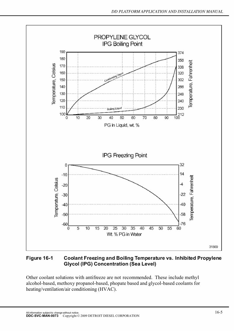
7/14/2019 Dd13-Dd15 a&i Manual
http://slidepdf.com/reader/full/dd13-dd15-ai-manual 251/304
DD PLATFORM APPLICATION AND INSTALLATION MANUAL
Figure 16-1 Coolant Freezing and Boiling Temperature vs. Inhibited PropyleneGlycol (IPG) Concentration (Sea Level)
Other coolant solutions with antifreeze are not recommended. These include methyl
alcohol-based, methoxy propanol-based, phopate based and glycol-based coolants for
heating/ventilation/air conditioning (HVAC).
All information subject to change without notice. 16-5DDC-SVC-MAN-0073 Copyright © 2009 DETROIT DIESEL CORPORATION
7/14/2019 Dd13-Dd15 a&i Manual
http://slidepdf.com/reader/full/dd13-dd15-ai-manual 252/304
COLD WEATHER STARTING AND STARTING AID SYSTEMS
Automotive coolant solutions with antifreeze are not suitable for Detroit Diesel heavy-duty
engines.
16.2.4 BATTERY
To provide the greatest amount of cranking energy, a high cold cranking ampere battery should be
specified. This requirement will result in the lowest battery internal resistance which will furnishthe maximum battery voltage at high cranking currents. If this is not possible, increase the number
of batteries for more cranking energy or use a higher voltage battery if possible.
Battery internal resistance is inversely proportional to the plate area. In order to reduce internal
resistance, battery plate area must be increased.
Batteries should be maintained at or near the full charged condition. A lead-acid battery should
have a specific gravity of 1.26 at 27°C (80°F).
A lead-acid battery is most ef ficient when operating at am bient temperatures of approximately
27°C (80°F). When operating at temperatures below -1.1°C (30°F), battery heaters may be
employed so that maximum power can be obtained from the battery.
As its internal temperature drops, a battery loses power. The state of the battery charge, as
determined by its specific gravity, also plays a significant role in the ability to start an engine in
cold temperatures. A battery with a 50% charge has 45% of its cranking power available at 27°C
(80°F), but the same battery will have only 20% of its cranking power at -1.1°C (0°F).
Battery size recommendations for the engine can be found at detroitdiesel.com. These
recommendations are for the bare engine only and do not reflect increases in battery capacity
required by parasitic loads imposed by the vehicle or other systems attached to the engine.
16-6 All information subject to change without notice.
DDC-SVC-MAN-0073 Copyright © 2009 DETROIT DIESEL CORPORATION

7/14/2019 Dd13-Dd15 a&i Manual
http://slidepdf.com/reader/full/dd13-dd15-ai-manual 253/304
DD PLATFORM APPLICATION AND INSTALLATION MANUAL
Figure 16-2 General Battery Cranking Power - Percent
16.2.5 STARTER MOTOR
Electric starter motors are recommended for use with Detroit Diesel engines. Other types of
starter motors exist, but are not generally recommended.
16.2.5.1 Electric Starter Motor
Correct motor size depends on the torque required to crank the engine and parasitic loads. Toobtain dependable starting, the starting motor must be capable of turning the engine and parasitic
loads. Cranking of the engine should not exceed 15 seconds or the starter and/or engine may be
damaged.
Cranking motor speed is directly proportional to the motor terminal voltage. To obtain the highest
motor terminal voltage, it is necessary to limit the cranking circuit resistance to less than .0008
ohms for this 12 volt systems.
All information subject to change without notice. 16-7DDC-SVC-MAN-0073 Copyright © 2009 DETROIT DIESEL CORPORATION

7/14/2019 Dd13-Dd15 a&i Manual
http://slidepdf.com/reader/full/dd13-dd15-ai-manual 254/304
COLD WEATHER STARTING AND STARTING AID SYSTEMS
The starting circuit design should be analyzed. The starting circuit includes the number and size
of batteries, cables including size, length and connectors, the starter and any device the starter
must rotate during cranking. This includes the engine and parasitic loads such as automatic
transmission, power steering pump, hydraulic pump(s), fan(s) and alternator(s). The Original
Equipment Manufacture must determine the lowest expected ambient temperature the vehicle
or application is expected to start.
All the information should be reviewed with the starter manufacture for further analysis andrecommendations of which starter motor is appropriate.
Generally, as parasitic loads increase and the ambient temperature decrease the cranking load
imposed on the starter motor increases causing a reduction in cranking speed.
For more information on DDC compliant electric starter motors, please refer to “Electrical
Systems” section of this manual.
16.3 COLD WEATHER STARTING
There are many different external hardware, engine components and approaches used to achieve
cold weather starting. This section contains these in the following topics:
□ Starting Systems
□ Starting Aids
□ Starting Procedures
□ Engine Starting Requirements
16.3.1 STARTING SYSTEMS
The following hardware systems are used to improve cold weather starting by reducing the
negative affects of low ambient temperatures. These systems may affect the engine starting
procedure.
16.3.1.1 Intake Air Heater
An intake air heater, or grid heater, comes standard on DD Platform engines. The grid heater
uses electric current to heat the air entering the intake manifold. The heated air temperature aids
in cold weather starting by increasing the temperature of the combustion fluid to a temperature
suitable for compression ignition.
16.3.1.2 Coolant Tank Type Heaters
Tank type heaters consist of resistance type elements mounted inside of a tank. Coolant enters
at one point of the tank and exits at a second point. Heated coolant rises to the top of the block
and is replaced by unheated coolant. Some tank type heaters contain a valve at the entrance to
the tank. This valve causes a "percolating" action and results in better circulation of coolant
through the engine. The valve also serves as a check valve and prevents coolant flow through
the heater during engine operation.
16-8 All information subject to change without notice.
DDC-SVC-MAN-0073 Copyright © 2009 DETROIT DIESEL CORPORATION

7/14/2019 Dd13-Dd15 a&i Manual
http://slidepdf.com/reader/full/dd13-dd15-ai-manual 255/304
DD PLATFORM APPLICATION AND INSTALLATION MANUAL
In order to obtain a rapid warm up of the coolant a separate coolant, a circulating pump should
be included with the tank type coolant heater. It is important that the heater is not energized
while the engine is running.
The tank type heater requires two connections to the engine coolant system. The tank inlet
connection must be taken from a point, which is low in the coolant syste m on the suction side of
the pump. The exit side of the heater should be connected to a coolant point high in the engine
cylinder block. It is important that the heater be installed inlet to pump suction to prevent a bypass coolant path during engine operation.
The tank type heater can be installed on any engine and can be designed with kW capacities large
enough to preheat the coolant in any engine. Various thermostat ranges may be chosen so that the
final temperature can be controlled as required.
It should be noted that these temperature rise charts are based on laboratory data. However, the
wattage requirements may vary slightly depending upon the location of the heating element
relative to the cylinder walls, the configuration of the coolant passages, and the flow rate of
coolant through the passages.
The wattage requirements specifi
ed are without wind considerations.This curve is based on a 12-hour heating time with 80% of the temperature rise occurring in the
first five hours of heating.
All information subject to change without notice. 16-9DDC-SVC-MAN-0073 Copyright © 2009 DETROIT DIESEL CORPORATION

7/14/2019 Dd13-Dd15 a&i Manual
http://slidepdf.com/reader/full/dd13-dd15-ai-manual 256/304
COLD WEATHER STARTING AND STARTING AID SYSTEMS
Figure 16-3 Watts Required to Raise Block Coolant Temperature to +30°F(-1.1°C) in in-line engines
16-10 All information subject to change without notice.
DDC-SVC-MAN-0073 Copyright © 2009 DETROIT DIESEL CORPORATION

7/14/2019 Dd13-Dd15 a&i Manual
http://slidepdf.com/reader/full/dd13-dd15-ai-manual 257/304
DD PLATFORM APPLICATION AND INSTALLATION MANUAL
16.3.1.3 Engine Block Heater
An engine block heater can be installed as an option on DD Platform engines. This heater
is installed into the M27x2 port on the oil module, next to the oil filter. For more detailed
information regarding this application, contact your application engineer.
16.3.1.4 Oil Pan Heater
Please refer to the section “Oil Immersion Heaters”.
16.3.1.5 Fuel
Refer to DDC publication Lubricating Oils, Fuel, and Filters (DDC-SVC-BRO–0001) available
at detroitdiesel.com.
16.3.1.6 Fuel Heaters
If blending or selection of fuels is not practical, then a fuel heater should be considered which
would assure fuel temperatures above the "cloud point". The "cloud point" of a fuel is the point
in which wax crystals begin to form in the fuel and begin to clog the fuel system. Fuel heaters
typically are used to raise the temperature of the fuel as it is sent to the engine. Increasing fuel
temperature above the "cloud point" prevents wax crystal formation and subsequent fuel line and
fuel filter plugging.
A fuel heater may not help start an engine with waxed fuel already in the engine.
Fuel heaters may generate heat by the use of an electric element, or use engine coolant or even
recalculate return fuel from the cylinder head to heat the incoming fuel. A fuel heater must be
thermostatically controlled to limit the heat input into the fuel and a shut off must be provided for the warmer time of the year. On DD Platform engines, the fuel temperature must not exceed
90°C (194°F) at the inlet to the high pressure fuel pump.
16.3.1.7 Battery Heater Types
It is essential that steps be taken to insure that the maximum battery capacity is available under
severe cold weather conditions. The electric battery warmers available can provide maximum
battery capacity but require an electrical power source for operation. This power source may be
an on-board system or an outside power supply. The following heaters usually use an outside
power supply in standby operations. It is advisable that the heater manufacturer be contacted for
the correct design, construction, and installation of their products. These units are available invarious sizes, wattage, and voltages.
All information subject to change without notice. 16-11DDC-SVC-MAN-0073 Copyright © 2009 DETROIT DIESEL CORPORATION

7/14/2019 Dd13-Dd15 a&i Manual
http://slidepdf.com/reader/full/dd13-dd15-ai-manual 258/304
COLD WEATHER STARTING AND STARTING AID SYSTEMS
Heater Type Description
Insulated Box Type
This unit can be fabricated from heavy gage sheet metal with rigid foam
insulation applied to the outer surfaces, or it may be of double-walled
formed-in-place urethane construction.
Plate Type
This unit employs a metal sheathed tubular element of "U" shaped sandwiched
between heavy gage sheet metal plates and equipped with an integral control
thermostat. This unit is mounted directly under the battery.
Mat Type
This unit is comprised of a heavy gage rubber material, incorporating a
serpentine pattern resistance wire element imbedded in the center area of the
material. The unit relies on low watt density radiant energy to heat the battery
and is intended to be mounted directly under the battery.
Strip Type
Commercially available strip heaters can be employed for heating batteries.
These are generally of higher watt densities. Care must be exercised to
ensure that they do not come into direct contact with the battery casing. It is
advisable to mount these units on the inside wall of the battery box.
Blanket Type
Flexible construction comprised of a heavy aluminum foil element assembly of
low watt density, complete with fiberglass insulation on one side, enclosed in a
heavy gage acid-resistant plastic sheath. The unit is provided with ties and
is intended to be installed tightly around the sides of the battery or batteries.
This unit has the advantage of integral insulation.
Air and Coolant Types
Other sources of battery heat in addition to electric heaters are forced hot air
or coolant. These either circulate hot air through the battery box or the use of
warm coolant circulated through passages in the battery box.
Table 16-1 Common Battery Heaters
16.3.1.8 Heating Engine Compartment
Another means of heating an engine is to use an external fuel fired air heater, which blows hot
air onto the engine oil pan, air inlet, and batteries. To make this system effective, the engine
compartment should be totally protected from the effects of outside wind, which will reduce theef ficiency of the heater. Care must be taken not to damage any electrical engine component
or wiring.
16.3.2 STARTING PROCEDURES
The engine starting procedure may change with the use any starting aid. Please review the
recommendations with each starting aid.
Changes to starting procedures because of cold weather may include:
□ A specific order of operation to achieve an engine start.
□ On electronically controlled engines this may include:
□ Automatic changes made by MCM to the fuel timing
□ Automatic operation of the Ether Start
□ Automatic setting and adjustment of high idle speed
□ A time delay for air intake heater operation.
16-12 All information subject to change without notice.
DDC-SVC-MAN-0073 Copyright © 2009 DETROIT DIESEL CORPORATION

7/14/2019 Dd13-Dd15 a&i Manual
http://slidepdf.com/reader/full/dd13-dd15-ai-manual 259/304
DD PLATFORM APPLICATION AND INSTALLATION MANUAL
□ Changes to the engine idle speed until the engine warms. On electronically controlled
engines, cold idle speed is accomplished automatically by factory preset speeds; options
for user specified higher idle speeds usually exist.
16.3.3 ENGINE STARTING REQUIREMENTS
A diesel engine creates enough heat during compression to initiate combustion when fuelis introduced. In cold weather, an engine may have to crank for a longer period in order to
generate suf ficient heat. Traditionally, starter motor manufactures' recommend cranking no
more than thirty seconds. Cranking an engine beyond 15 seconds, especially in warmer ambient
temperatures, may cause damage to the starter motor and/or engine.
16.4 COLD WEATHER OPERATION
There are a number of precautions and special practices which should be followed to ensure
satisfactory engine operation in cold temperatures.
16.4.1 ETHER INJECTION
The installation of an ether injection device on a DD Platform engine is strictly prohibited. The
injection of ether ,or any other substance, into the air intake system for improved cold start
capability could result in serious engine damage and/or severe personal injury.
16.4.2 IDLING AND LIGHT LOAD
Idling of the engine should be avoided and light load operation restricted to a minimum. Where
idling represents an unavoidable part of the load cycle, the idling speed should be increased to
approximately 800 to 1000 rpm. If prolonged light load operation cannot be avoided, the engineshould be periodically operated at a higher speed until lube oil and coolant reach the normal
operating temperature.
16.4.3 MAINTENANCE
For optimum performance at low temperatures, there should be no loss of compression due to
worn rings or leaking valves. Consequently the engine condition, rings and valves should be
checked prior to cold weather to ensure proper operation at low temperatures. Fuel tanks should
be kept filled. This practice will aid in reducing tank condensation and will insure the quality of
the fuel. Change fuel filters at recommended intervals and when the grade of fuel is switched.
Please refer to service literature at detroitdiesel.com for details.
All information subject to change without notice. 16-13DDC-SVC-MAN-0073 Copyright © 2009 DETROIT DIESEL CORPORATION

7/14/2019 Dd13-Dd15 a&i Manual
http://slidepdf.com/reader/full/dd13-dd15-ai-manual 260/304
COLD WEATHER STARTING AND STARTING AID SYSTEMS
16.4.4 WIND PROTECTION
Non-operating engines should be protected from wind, snow, and rain by compartment curtains,
shield or shroud. These may be needed in extreme cold weather conditions when the vehicle is
operating. Wind can quickly dissipate the heat from the engine oil, coolant, fuel and battery
heaters. This effect is known as wind chill factor. It should be noted that wind chill factor cannot
take the temperature of an object to a point lower than the ambient air temperature. The oil panshould be protected from cold air blasts. A shield or shroud should be provided which will deflect
the air away from the pan thus preventing sludge from forming in the oil pan. The oil pan shroud
should allow an oil temperature no greater than 121°C (250°F) while the engine is operating. The
curtain, shield or shroud must be removed in warm weather conditions.
16.4.5 BATTERY AND CHARGING SYSTEM
The battery should always be maintained in a high state of charge. This can be accomplished
by specifying an alternator capable of supporting electrical accessory loads at idle speeds and
keeping the cable connections tight.
16.4.6 AIR CLEANER MAINTENANCE
The air cleaner should be inspected for plugging by moisture, snow or ice formation. In some
cases, snow or moisture laden air will plug or wet the air cleaner element. A wet, air cleaner
element may be more susceptible to mechanical damage. Minute droplets of salt spray ingested
into the engine through the air cleaner element can cause damage to internal components. Ice can
also form in cold temperatures in air cleaners with wet elements, leading to possible turbocharger
damage. If evidence of wet or plugged filters is observed, steps must be taken to provide air flow
to the engine which is snow or moisture free. This may require a revision to the vehicle air intake
system. Please refer to the service literature available at detroitdiesel.com for details.
16.4.7 SUPPLEMENTAL HEATING DEVICE
Supplemental heating devices add heat to the engine while the engine is running. The additional
heat allows the engine to maintain the proper operating temperature under extreme cold weather
conditions. The need for such system can be affected by the design of the engine installation
and is typically location dependent.
16.4.8 DDC COLD START RECOMMENDATIONS
DDC cold start recommendations are below.
16-14 All information subject to change without notice.
DDC-SVC-MAN-0073 Copyright © 2009 DETROIT DIESEL CORPORATION

7/14/2019 Dd13-Dd15 a&i Manual
http://slidepdf.com/reader/full/dd13-dd15-ai-manual 261/304
DD PLATFORM APPLICATION AND INSTALLATION MANUAL
ITEM Above 14°F Below 14°F
1 - API CJ-4, low ash oil: 15W-40
1 - SAE 5W-30, 10W-30, 5W-40,
10W-40
*must still be API CJ-4*
Lube Oil Classification API CJ-4 Lube oils must meet appropriate API CJ-4 performance levels as described
in DDC publication (DDC-SVC-BRO–0001), Lubricating Oils, Fuel, andFilters, available on the DDC www.detroitdiesel.com.
Use of synthetic oil permitted within constraints also defined in DDC
publication (DDC-SVC-BRO–0001).
Fuel OilCloud point must be 10°F below the lowest anticipated operating temperature.
Refer to DDC publication DDC-SVC-BRO–0001 for details.
Coolant 50/50 antifreeze-water
1 — 50/50 DD Power Cool-Water
2 - 60/40 DD Power Cool-Water, if
anticipated operating temperature
will be -40°F or below.
Electrical Capacity
(Battery Capacity CCA @ 0°F)Engine only
DD Platform - 12V - 1875 CCA
Applies only when using DDC factory recommended wire sizes and length.
Other Starting AidsUsually not required above 32°F but
may be used if desired below 32°F.
Lube oil heaters, coolant heaters,
battery warmers, etc. (singly or
in combination) may be required
depending on oil choice.
Table 16-2 DDC Cold Start Recommendations - DD Platform Engine
All information subject to change without notice. 16-15DDC-SVC-MAN-0073 Copyright © 2009 DETROIT DIESEL CORPORATION

7/14/2019 Dd13-Dd15 a&i Manual
http://slidepdf.com/reader/full/dd13-dd15-ai-manual 262/304
COLD WEATHER STARTING AND STARTING AID SYSTEMS
THIS PAGE INTENTIONALLY LEFT BLANK
16-16 All information subject to change without notice.
DDC-SVC-MAN-0073 Copyright © 2009 DETROIT DIESEL CORPORATION

7/14/2019 Dd13-Dd15 a&i Manual
http://slidepdf.com/reader/full/dd13-dd15-ai-manual 263/304
DD PLATFORM APPLICATION AND INSTALLATION MANUAL
17 ACCESSORY DRIVE SYSTEM
Section Page
17.1 ACCESSORY DRIVES ........................................................................... 17- 2
17.2 GEARTRAIN ........................................................................................... 17- 2
17.3 DRIVETRAIN .......................................................................................... 17- 4
17.4 BENDING MOMENT ............................................................................... 17- 5
All information subject to change without notice. 17-1DDC-SVC-MAN-0073 Copyright © 2009 DETROIT DIESEL CORPORATION

7/14/2019 Dd13-Dd15 a&i Manual
http://slidepdf.com/reader/full/dd13-dd15-ai-manual 264/304
ACCESSORY DRIVE SYSTEM
17.1 ACCESSORY DRIVES
There are no accessory drives Rear Engine Power Take-Off (REPTO) located on the flywheel
housing for the DD Platform engine at this time.
The Accessory Drives Front Engine Power Take-off (FEPTO) located on the front cover housing
are listed in Table 1–1 and Table 1–2 below.
Accessory/Location
Front Cover HousingDrive Ratio
Rotation (as
viewed from
front of engine)
Drive
Type
(SAE
Flange)
Comments
Vibration Damper Pulley
off Front Crankshaft-- CW
8 groove
Poly-V
w/10
groove
Poly-V
Z53700903
Z53700904
Z53700908
Table 17-1 DD Platform Accessory Drives on Crankshaft (Non-Gear Driven)
Accessory /
Location Front
Cover Housing
Drive
Ratio
Rotation
(as
viewed
from
front of
engine)
Shaft
Coupling
(SAE)
Drive
type (SAE
Flanges)
Capacity in
lb·ft @ rpmComments
PTO Front Crankshaft — CWSpicer
1350
4 groove
pulley
224 lb·ft (77hp)
@ 1800rpm
PTO Front Crankshaft — CWSpicer
1310
4 groove
pulley
120 lb·ft (41hp)
@ 1800rpm
PTO Front Crankshaft — CW
Spicer
1350
10 groove
pulley
224 lb·ft (77hp)
@ 1800rpm
* An adaptor is necessary for adaptation of the PTO Front Crankshaft Accessory Drive to adapt to DD
Platform Vibration Damper Pulley
† Maximum combined PTO of accessory drive plus front drive not to exceed 25 hp continuous, 30 hp
intermittent @ rated engine speed
Table 17-2 DD Platform Accessory Drives on Crankshaft (Gear Driven)
17.2 GEARTRAIN
The geartrain for a DD Platform engine is located at the rear of the engine. The geartrain consists
of intake and exhaust camshaft gears, idler gears 1-5, crankshaft gear, oil pump gear, fuel pump
gear, air compressor gear, and turbocompound gear.
17-2 All information subject to change without notice.
DDC-SVC-MAN-0073 Copyright © 2009 DETROIT DIESEL CORPORATION

7/14/2019 Dd13-Dd15 a&i Manual
http://slidepdf.com/reader/full/dd13-dd15-ai-manual 265/304
DD PLATFORM APPLICATION AND INSTALLATION MANUAL
1. Idler Gear No. 1 9. Crankshaft Gear 2. Idler Gear No. 2 10. Oil Pump Gear
3. Idler Gear No. 3 (Adjustable) 11. Camshaft Gear Exhaust
4. Idler Gear No. 4 (Optional on DD13 with REPTO) 12. Camshaft Gear Intake
5. Idler Gear No. 5 A. Level A
6. Air Compressor Gear* B. Level B
7. Fuel Pump Gear** C. Level C
8. Axial Power Turbine Gear (N/A for DD13)* x. To Front of Engine
NOTE: * Power Steering Pump mounted to rear of Air Compressor for 1–cylinder
Air Compressor applications. PSP driven by Air Compressor driveshaft.
** Power Steering Pump mounted to front of Fuel Pump for 2–cylinder Air Compressor applications
Figure 17-1 Rear Geartrain for the DD Platform Engine
17.2.1 GEARTRAIN GEAR DRIVE RATIOS
Gear drive ratios for the gear drives on a DD Platform engine.
All information subject to change without notice. 17-3DDC-SVC-MAN-0073 Copyright © 2009 DETROIT DIESEL CORPORATION

7/14/2019 Dd13-Dd15 a&i Manual
http://slidepdf.com/reader/full/dd13-dd15-ai-manual 266/304
ACCESSORY DRIVE SYSTEM
Figure 17-2 GEARTRAIN GEAR DRIVE RATIOS
17.3 DRIVETRAIN
The standard drivetrain for a DD Platform engine contains the water pump, vibration damper
pulley, and a tensioner driven by a drive belt. The vibration damper pulley consists of 2 Poly-V
crankshaft pulleys integrated into one combined pulley. The inner plane of the pulley is an
8–groove pulley, which drives the waterpump, alternator, and freon compressor. The outer plane
of the vibration damper pulley is a 10–groove pulley, which drives the fan drive system. The drive
ratio of the water pump is 2.22:1 for the DD Platform engine and 2.05:1 for the DD Platformengine. See Figure 1–3 for a schematic of the DD Platform drivetrain.
17-4 All information subject to change without notice.
DDC-SVC-MAN-0073 Copyright © 2009 DETROIT DIESEL CORPORATION

7/14/2019 Dd13-Dd15 a&i Manual
http://slidepdf.com/reader/full/dd13-dd15-ai-manual 267/304
DD PLATFORM APPLICATION AND INSTALLATION MANUAL
1. Waterpump Pulley 6. Tensioner
2. Idler Pulley 7. Tensioner
3. Crank 8. Tensioner
4. Generator 9. Cooling Fan
5. Freon Compressor 10. Idler
Figure 17-3 DD Platform DRIVETRAIN
17.4 BENDING MOMENT
The bending moment (M) on the front of the crank equals force (F) times distance (L) from the
front face of the block. The force is usually caused by belt tension on the crankshaft pulleys .
The maximum allowable bending moment depends upon the angled direction that the force
around the crank (as referenced from the front face of the engine) is to be applied. For multiple
hub loads, take the vectorial sum of the maximum allowable bending moments at each angled
direction of force to determine the total maximum allowable bending moment.
The front crankshaft maximum allowable polar bending moment diagram is in ft·lb and referenced
from the front face of the block.
All information subject to change without notice. 17-5DDC-SVC-MAN-0073 Copyright © 2009 DETROIT DIESEL CORPORATION

7/14/2019 Dd13-Dd15 a&i Manual
http://slidepdf.com/reader/full/dd13-dd15-ai-manual 268/304
ACCESSORY DRIVE SYSTEM
Figure 17-4 DD Platform 14.8L Allowable Front Crankshaft Bending Moment
To calculate the maximum allowable force (F) at a given belt load direction:
1. Determine the direction the individual force is to be applied from a belt drive analysis or
from a belt layout diagram.
2. Find the corresponding maximum allowable bending moment.
3. Divide by the corresponding distance (L) to derive the maximum allowable force (F).
L is the distance from the fr ont face of the block to the centerline of the belt driving the load and ismathematically defined as L
1+ .99 in., where .99 in. is a constant value and represents the distance
between the front face of the block to the rear face of the vibration damper pulley. L1
is then the
distance from the rear face of the vibration damper pulley to the centerline of the belt or pulley.
17-6 All information subject to change without notice.
DDC-SVC-MAN-0073 Copyright © 2009 DETROIT DIESEL CORPORATION

7/14/2019 Dd13-Dd15 a&i Manual
http://slidepdf.com/reader/full/dd13-dd15-ai-manual 269/304
DD PLATFORM APPLICATION AND INSTALLATION MANUAL
Figure 17-5 Bending Moment on the Front of the Crank
If multiple belts are used to drive multiple loads, use the distance to the centerlines of each belt
when determining each force applied. Refer to Table below for a description of the Lx
values for
the DD Platform poly-v vibration damper pulley configuration and for a schematic representation
of the Lx
values.
Poly-V Vibration
Damper Pulley Group
8–groove L1
mm (in)
10–groove L2
mm (in)
Z53700903,
Z53700904, Z5370090821.46 (.84) 76.06 (2.99)
Table 17-3 DD Platform Vibration Damper Pulley Lx
Values
All information subject to change without notice. 17-7DDC-SVC-MAN-0073 Copyright © 2009 DETROIT DIESEL CORPORATION
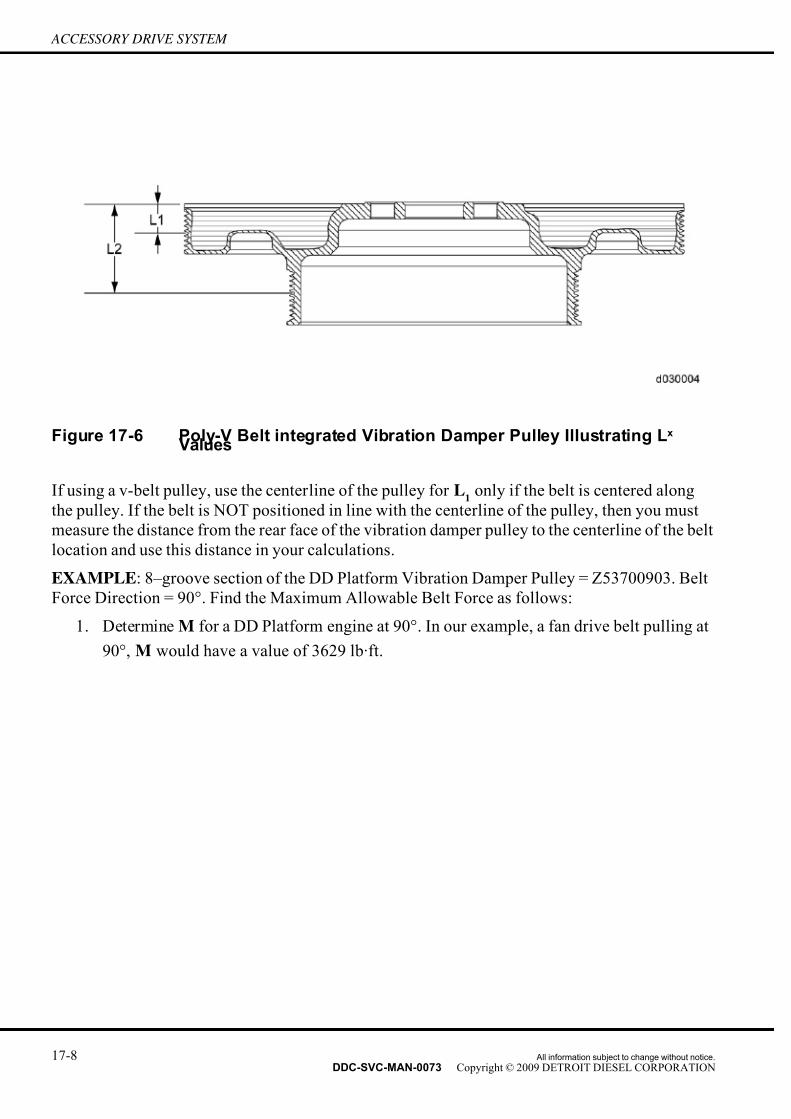
7/14/2019 Dd13-Dd15 a&i Manual
http://slidepdf.com/reader/full/dd13-dd15-ai-manual 270/304
ACCESSORY DRIVE SYSTEM
Figure 17-6 Poly-V Belt integrated Vibration Damper Pulley Illustrating Lx
Values
If using a v-belt pulley, use the center line of the pulley for L1
only if the belt is centered along
the pulley. If the belt is NOT positioned in line with the centerline of the pulley, then you must
measure the distance from the rear face of the vibration damper pulley to the centerline of the belt
location and use this distance in your calculations.
EXAMPLE: 8–groove section of the DD Platform Vibration Damper Pulley = Z53700903. Belt
Force Direction = 90°. Find the Maximum Allowable Belt Force as follows:
1. Determine M for a DD Platform engine at 90°. In our example, a fan drive belt pulling at
90°, M would have a value of 3629 lb·ft.
17-8 All information subject to change without notice.
DDC-SVC-MAN-0073 Copyright © 2009 DETROIT DIESEL CORPORATION

7/14/2019 Dd13-Dd15 a&i Manual
http://slidepdf.com/reader/full/dd13-dd15-ai-manual 271/304
DD PLATFORM APPLICATION AND INSTALLATION MANUAL
Figure 17-7 Net Belt Tension at the 90° Position
2. Determine L by using the formula L = L1
+ .99 in. In our example, we use the table to find
L1
for the vibration damper pulley group Z53700903 (8–groove section). This value is
.84 in. Therefore, L = .99 in. + .84 in. = 1.83 in. (.15 ft.)
3. Find F using the formula F = M /L. In the example, F= 3629 lb·ft/.15 ft. = 24193 lbs (F) .
4. Therefore the net total static belt tension (each leg of the belt x 2) should be no more than
lbs at the 90° position of the 8–groove section of the vibration damper pulley.
If there are fan belts and other accessories, then the combined net force should be calculated at its
resultant angle. Contact Detroit Diesel Application Engineering for assistance.
All information subject to change without notice. 17-9DDC-SVC-MAN-0073 Copyright © 2009 DETROIT DIESEL CORPORATION

7/14/2019 Dd13-Dd15 a&i Manual
http://slidepdf.com/reader/full/dd13-dd15-ai-manual 272/304
ACCESSORY DRIVE SYSTEM
THIS PAGE INTENTIONALLY LEFT BLANK
17-10 All information subject to change without notice.
DDC-SVC-MAN-0073 Copyright © 2009 DETROIT DIESEL CORPORATION

7/14/2019 Dd13-Dd15 a&i Manual
http://slidepdf.com/reader/full/dd13-dd15-ai-manual 273/304
DD PLATFORM APPLICATION AND INSTALLATION MANUAL
18 AUXILIARY POWER UNITS (APU)
Section Page
18.1 AUXILIARY POWER UNITS (APU) ........................................................ 18- 2
18.2 APU DESCRIPTION ............................................................................... 18- 2
18.3 INSTALLATION REQUIREMENTS ......................................................... 18- 3
18.4 APU ENGINE START-UP PROCEDURE ............................................... 18-11
18.5 EXAMPLE INSTALLATION PHOTOS ..................................................... 18-13
All information subject to change without notice. 18-1DDC-SVC-MAN-0073 Copyright © 2009 DETROIT DIESEL CORPORATION

7/14/2019 Dd13-Dd15 a&i Manual
http://slidepdf.com/reader/full/dd13-dd15-ai-manual 274/304
AUXILIARY POWER UNITS (APU)
18.1 AUXILIARY POWER UNITS (APU)
Auxiliary Power Units (APU) are optional systems, either factory installed or af ter-market, that
are driven by an independent power source and provide electricity (either 12-volt, 120-volt or
both) and HVAC functions for on-highway trucks to eliminate excessive engine idling during long
duration or over-night stops. Some states have regulations limiting idle time to no more than five
minutes, at which point the main vehicle engine must automatically shut down. For an overnightstay in a sleeper cab, HVAC functions or electrical power are often required for driver comfort.
NOTE:
The installation described herein is specific to the ThermoKing TriPac APU installed witha Detroit Diesel DD15 engine. These guidelines should be applicable to other brand or
model APU’s. Please confirm the installation requirements for different model APUs
with Detroit Diesel Application Engineering.
18.2 APU DESCRIPTION
An APU is typically comprised of a small diesel engine, an in-cab control panel, a thermostat, analternator, an air conditioning circuit, a heater circuit, and in some cases, a generator to provide
120-volt power. The APU is engaged when the main vehicle engine is shut off to provide heating
and cooling, charge the batteries and provide 12-volt or 120-volt power for small appliances,
laptop computers, etc. The APU can be set up to start automatically when the engine is stopped
or can be switched on manually. Some APUs may also have a battery monitor function which
will engage the APU while the main vehicle engine is running to charge the batteries in the
event of an alternator failure.
18-2 All information subject to change without notice.
DDC-SVC-MAN-0073 Copyright © 2009 DETROIT DIESEL CORPORATION

7/14/2019 Dd13-Dd15 a&i Manual
http://slidepdf.com/reader/full/dd13-dd15-ai-manual 275/304
DD PLATFORM APPLICATION AND INSTALLATION MANUAL
1. A/C Condenser 8. Truck's Heater Core2. Receiver Dryer 9. Truck's Engine
3. A/C Evaporator 10. Fuel Pick-Up Tubes
4. Heater 11. Truck's Fuel Tank
5. Heater Exhaust 12. TriPac APU
6. Heater Intake 13. Truck's Sleeper
7. Heater Fuel Pump
Figure 18-1 TriPac Components
18.3 INSTALLATION REQUIREMENTS
The installation requirements for APUs vary from brand to brand. Some are completely
independent systems and require no interface with the main vehicle engine systems. Other
APUs require the coolant circuit for the APU to be shared with the main vehicle engine cooling
circuit. The installation of an APU should only be performed by the vehicle manufacturer or
an authorized after-market APU dealer or distributor. The installation of an APU should not
compromise or inhibit the required function of any engine systems described in this manual.
Component or system failures that result from not following these guidelines could result in
engine or vehicle warranty coverage being denied.
All information subject to change without notice. 18-3DDC-SVC-MAN-0073 Copyright © 2009 DETROIT DIESEL CORPORATION

7/14/2019 Dd13-Dd15 a&i Manual
http://slidepdf.com/reader/full/dd13-dd15-ai-manual 276/304
AUXILIARY POWER UNITS (APU)
18.3.1 APU FUEL SYSTEM
Most APUs share the fuel supply with the primary vehicle fuel tank. Separate fuel sup ply and
return lines must be installed for the APU’s diesel engine directly to the primary vehicle fuel tank.
Connection to engine supply and return fuel lines is not permitted. Material specifications and
line sizes will be indicated by the manufacturer of the APU being installed. It is important to
also consider the location of the APU relative to the vehicle fuel tank to avoid siphoning or other unwanted scenarios. If any modifications are performed on the fuel tank, make sure the fuel tank
is cleaned of debris prior to engine operation.
FIRE
To avoid injury from fire, contain and eliminate leaks of
flammable fluids as they occur. Failure to eliminate leaks
could result in fire.
18-4 All information subject to change without notice.
DDC-SVC-MAN-0073 Copyright © 2009 DETROIT DIESEL CORPORATION

7/14/2019 Dd13-Dd15 a&i Manual
http://slidepdf.com/reader/full/dd13-dd15-ai-manual 277/304
DD PLATFORM APPLICATION AND INSTALLATION MANUAL
1. Adapter Plate 4. Threaded Ferrule2. Pick-Up Tube Assembly 5. Back-Up Washer
3. Nut 6. Warning Label
Figure 18-2 Fuel Pick-Up Tool Installation
1. Drilling Template 4. Threaded Ferrule
2. Pick-Up Tube Assembly 5. Back-Up Washer
3. Nut 6. Warning Label
Figure 18-3 Fuel Pick-Up Tool Installation Alternate Installation
All information subject to change without notice. 18-5DDC-SVC-MAN-0073 Copyright © 2009 DETROIT DIESEL CORPORATION

7/14/2019 Dd13-Dd15 a&i Manual
http://slidepdf.com/reader/full/dd13-dd15-ai-manual 278/304
AUXILIARY POWER UNITS (APU)
18.3.2 APU COOLANT SYSTEM
If the APU shares coolant with the main vehicle engine, it is important that the APU in stallation
does not create problems for the main engine cooling system. The installation method preferred
by Detroit Diesel uses coolant lines connected directly to the main vehicle engine to supply
coolant to the APU. Detroit Diesel does not allow the APU coolant circuit to be connected to the
bunk heater circuit due to insuf ficient coolant flow. Material specifications and line sizes will be indicated by the manufacturer of the APU being installed.
Figure 18-4 Coolant Hose Installation
NOTICE:
An air bound pump cannot adequately circulate coolant. This can
lead to overheating and severe engine damage.
PERSONAL INJURY
To avoid injury from rotating belts and fans, do not remove
and discard safety guards.
18-6 All information subject to change without notice.
DDC-SVC-MAN-0073 Copyright © 2009 DETROIT DIESEL CORPORATION

7/14/2019 Dd13-Dd15 a&i Manual
http://slidepdf.com/reader/full/dd13-dd15-ai-manual 279/304
DD PLATFORM APPLICATION AND INSTALLATION MANUAL
HOT COOLANT
To avoid scalding from the expulsion of hot coolant, never
remove the cooling system pressure cap while the engine isat operating temperature. Wear adequate protective clothing
(face shield, rubber gloves, apron, and boots). Remove thecap slowly to relieve pressure.
NOTICE:
Cooling systems that cannot be drained completely may also
experience freeze cracking of components. Additional drain(s)
and a caution notice should be provided by the OEM to ensurecomplete draining of the cooling system.
Three (3) coolant supply ports are located at the rear of the coolant collector as shown below.
These ports are M22 x 1.5 ISO threads. A coolant return manifold is available through Daimler
Trucks North America in either a 2-port or 4-port configuration. The 4-port configuration is
standard on Freightliner sleeper cab units. For trucks built with a 2-port manifold, an additional
port is required for the APU coolant return. Two options exist: 1) replace the 2-port manifold
with a 4-port manifold; 2) install a tee fitting or “Y” fitting at the rear port. The coolant return
ports are ½” FPT threads. A shut-off valve should be installed on the APU coolant supply and
APU coolant return lines. These shut-off valves should be located as close to the engine ports as
practical. Care should be taken with the routing of coolant supply and return lines for the APU
not to locate the lines too close to exhaust system components. The APU coolant return should be
routed to either of the two r ear-most ports on the 4-port manifold.
All information subject to change without notice. 18-7DDC-SVC-MAN-0073 Copyright © 2009 DETROIT DIESEL CORPORATION

7/14/2019 Dd13-Dd15 a&i Manual
http://slidepdf.com/reader/full/dd13-dd15-ai-manual 280/304
AUXILIARY POWER UNITS (APU)
Figure 18-5 DD15 with 4-Port Coolant Return Manifold
Coolant supply and return lines should be routed away from the turbocharger turbine housing and
any exhaust components. Both lines should be routed forward of the turbocharger compressor
discharge elbow and below the turbo inlet, down toward the frame rail. The lines should be
securely fastened to the engine so as not to unnecessarily stress the fittings which may result in
coolant leaks. Avoid sharp bends and angles whenever possible. A minimum spacing of 13mm
is required between coolant lines and the frame rails. See photographic examples of coolant
line routings in the last section of this chapter.
Figure 18-6 DD15 with 2-Port Coolant Return Manifold
18-8 All information subject to change without notice.
DDC-SVC-MAN-0073 Copyright © 2009 DETROIT DIESEL CORPORATION

7/14/2019 Dd13-Dd15 a&i Manual
http://slidepdf.com/reader/full/dd13-dd15-ai-manual 281/304
DD PLATFORM APPLICATION AND INSTALLATION MANUAL
DD15 engine shown with 2-port coolant return manifold. For installations having a 2-port
manifold, the rear coolant line (bunk heater return) should be used to return coolant from the
APU. If a tee fitting is used, it should be installed into the rear port of the manifold. The bunk
heater return is connected to the outboard port on the tee, and the APU coolant return is plumbed
to the rear facing port on the tee. A “Y” connector could also be used to connect to APU return to
the bunk heater return line.
Refer to Detroit Diesel Coolant Selections Bulletin, 7SE298, for proper selection of enginecoolant and additives.
If an APU is selected that shares engine coolant with the main vehicle engine and could also
run simultaneously, an installation review would be required from Detroit Diesel Application
Engineering prior to installation.
18.3.3 APU EXHAUST SYSTEM
The APU exhaust system must remain separate from the main vehicle engine exhaust system.
Under no circumstances should the APU exhaust be connected to the main vehicle exhaust piping.
Care should be taken to route the APU exhaust away from the cab and all air intake locations.
18.3.4 APU ELECTRICAL SYSTEM
If the APU requires input from the main vehicle engine electronics to indicate when the main
vehicle engine is running, the ignition signal from the main vehicle engine is located in the CPC
on pin #3 of connector #2.
All information subject to change without notice. 18-9DDC-SVC-MAN-0073 Copyright © 2009 DETROIT DIESEL CORPORATION

7/14/2019 Dd13-Dd15 a&i Manual
http://slidepdf.com/reader/full/dd13-dd15-ai-manual 282/304
AUXILIARY POWER UNITS (APU)
Figure 18-7 CPC Connectors
The part numbers for CPC pins are listed below.
Part DDC Part Number
CPC - socket 0.5-1.0mm wire (single) 013 545 76 26
CPC - socket 1.0-2.5mm wire (single) 013 545 78 26
Table 18-1 CPC Pins
The vehicle ignition is a 12-volt signal. No other electrical signals should be required from the
main vehicle engine electronics. If the APU requires vehicle battery power, please refer to the
main Electrical System section of the DD15 Application & Installation Manual.
18-10 All information subject to change without notice.
DDC-SVC-MAN-0073 Copyright © 2009 DETROIT DIESEL CORPORATION

7/14/2019 Dd13-Dd15 a&i Manual
http://slidepdf.com/reader/full/dd13-dd15-ai-manual 283/304
DD PLATFORM APPLICATION AND INSTALLATION MANUAL
NOTICE:
Do not mount the alternator and / or generator near exhaustcomponents that radiate substantial heat. Mounting near
substantial heat sources could overheat the alternator, generator and / or regulator.
18.4 APU ENGINE START-UP PROCEDURE
It is important to verify the installation has been performed correctly and to prepare the various
APU sub-systems for proper operation. The A/C circuit, the lubrication system, the cooling
system, and the fuel system all must be in proper working condition before the APU is started for
the first time to avoid unnecessary component damage.
DO NOT operate the APU engine before a partial refrigerant
charge has been added or damage to the A/C compressor
will result.
NOTICE:
BEFORE operating the APU engine check the oil level. Add the
proper amount and type of oil, if needed.
18.4.1 BLEEDING THE COOLANT SYSTEM
Bleed as follows:
1. Verify the APU OUTLET hand valve is CLOSED. If this valve is left open, coolant will
be sitting on top of the TriPac thermostat and not allow the TriPac engine to bleed air.
2. Open the APU INLET hand valve.
3. Place a clean container under the bleed line to catch coolant that is drained.
4. Entrapped air must be purged from the main vehicle engine after filling the cooling
system. To do this, allow the engine to warm up with the pressure cap removed. With
the transmission in neutral, increase engine speed to 1,000 rpm and add coolant to the
surge tank as required.5. Open the bleed petcock on the APU engine to allow air to bleed out.
6. When a steady stream of coolant flows from the bleed line, close the petcock.
7. Open the APU OUTLET hand valve.
8. Replace drained coolant from the TriPac back into the tractor’s radiator.
9. Bleed Tr iPac fuel system. Refer to section "Bleeding The Fuel Lines".
All information subject to change without notice. 18-11DDC-SVC-MAN-0073 Copyright © 2009 DETROIT DIESEL CORPORATION

7/14/2019 Dd13-Dd15 a&i Manual
http://slidepdf.com/reader/full/dd13-dd15-ai-manual 284/304
AUXILIARY POWER UNITS (APU)
Verify the APU engine has proper amount of oil and the A/Csystem has a partial refrigerant charge before starting the
engine.
10. Start the TriPac engine.
11. The remaining air in the system will be forced to the tractor radiator and the TriPac APU
should now be bled of all air.
18.4.2 BLEEDING THE FUEL LINES
Bleed as follows:
1. Locate the On/OFF switch inside the APU and turn the switch “ON”.
2. Open the fuel return line banjo fitting on the APU engine.
3. At the HMI (in-cab APU control panel):
[a] Press MAIN POWER Key “ON”.
[b] Press APU SYSTEM Key “ON”.
[c] Press MODE Key to “AC”.
[d] Press FAN Key to set fan speed.
[e] Press UP or DOWN Keys to set the thermostat to 50°F (10°C).
[f] Multiple start attempts will be required to start the engine.
NOTE:The fuel pump only runs when the engine is turning over. If the engine cranks for 30seconds and fails to start, a start fault shutdown will be generated. This alarm code will
have to be cleared bef ore attempting another start sequence.
4. Close the fuel return line banjo fitting when a steady flow of fuel is observed.
5. Allow engine to start.
18.4.3 VERIFYING ENGINE OPERATION
Once the APU engine is running:
□ Verify with a strobe light tachometer the engine rpm is 1800 RPM loaded (A/C clutch
engaged). Adjust as required.
□ Check cooling system for leaks
□ Check for fuel leaks
18-12 All information subject to change without notice.
DDC-SVC-MAN-0073 Copyright © 2009 DETROIT DIESEL CORPORATION

7/14/2019 Dd13-Dd15 a&i Manual
http://slidepdf.com/reader/full/dd13-dd15-ai-manual 285/304
DD PLATFORM APPLICATION AND INSTALLATION MANUAL
□ Check for oil leaks
□ Check for exhaust leaks
□ Verify with a digital meter that the charging voltage at the battery cables is at least 13.6 Vdc.
18.5 EXAMPLE INSTALLATION PHOTOS
Figure 18-8 Coolant Supply Ports
Coolant supply ports located on coolant collector, upper right side of engine, near back of rocker
cover. Coolant supply for APU has not yet been installed on third, rear-most ISO port. Cab heater
and bunk heater supply lines are installed on the two forward ISO supply ports of the coolantcollector.
All information subject to change without notice. 18-13DDC-SVC-MAN-0073 Copyright © 2009 DETROIT DIESEL CORPORATION

7/14/2019 Dd13-Dd15 a&i Manual
http://slidepdf.com/reader/full/dd13-dd15-ai-manual 286/304
AUXILIARY POWER UNITS (APU)
Figure 18-9 Two-Port Coolant Return Manifold
Top of engine showing two-port coolant return manifold (mounted) with replacement four-port
manifold waiting to be installed.
Figure 18-10 Four-Port Coolant Return Manifold
18-14 All information subject to change without notice.
DDC-SVC-MAN-0073 Copyright © 2009 DETROIT DIESEL CORPORATION

7/14/2019 Dd13-Dd15 a&i Manual
http://slidepdf.com/reader/full/dd13-dd15-ai-manual 287/304
DD PLATFORM APPLICATION AND INSTALLATION MANUAL
Figure 18-11 Four-Port Coolant Return Manifold Installed
Four-port coolant return manifold installed with cab heater return, bunk heater return, fuel tank
heater return, and APU coolant return lines installed.
Figure 18-12 Right Side View Of Engine After APU Installation
Right side view of engine after APU installation completed. Two yellow handled shut-off valves
in upper left are installed on APU supply and fuel tank heater supply lines. Lower shut-off
valves are installed on APU and fuel tank heater return lines. Note line routing, away from
exhaust components, forward of turbo compressor housing, inboard of CAC inlet tubing, and
down into f rame rail.
All information subject to change without notice. 18-15DDC-SVC-MAN-0073 Copyright © 2009 DETROIT DIESEL CORPORATION

7/14/2019 Dd13-Dd15 a&i Manual
http://slidepdf.com/reader/full/dd13-dd15-ai-manual 288/304
AUXILIARY POWER UNITS (APU)
Figure 18-13 Coolant Lines
Coolant lines clipped to bracket on freon compressor bracket.
Figure 18-14 Alternate View
Alternate view of coolant line clipping at freon compressor.
18-16 All information subject to change without notice.
DDC-SVC-MAN-0073 Copyright © 2009 DETROIT DIESEL CORPORATION

7/14/2019 Dd13-Dd15 a&i Manual
http://slidepdf.com/reader/full/dd13-dd15-ai-manual 289/304
DD PLATFORM APPLICATION AND INSTALLATION MANUAL
19 EFFECTS OF ENVIRONMENTAL CONDITIONS
Section Page
19.1 EFFECTS OF ENVIRONMENTAL CONDITIONS DESCRIPTION ......... 19- 2
19.2 AIR INLET TEMPERATURE ................................................................... 19- 2
19.3 EXHAUST BACK PRESSURE ................................................................ 19- 2
19.4 FUEL TEMPERATURE ........................................................................... 19- 3
19.5 ALTITUDE ............................................................................................... 19- 3
All information subject to change without notice. 19-1DDC-SVC-MAN-0073 Copyright © 2009 DETROIT DIESEL CORPORATION

7/14/2019 Dd13-Dd15 a&i Manual
http://slidepdf.com/reader/full/dd13-dd15-ai-manual 290/304
EFFECTS OF ENVIRONMENTAL CONDITIONS
19.1 EFFECTS OF ENVIRONMENTAL CONDITIONSDESCRIPTION
Power developed by any internal combustion engine depends on the amount of fuel burned with
the available oxygen in the cylinder. The amount of oxygen in a cubic foot of air is reduced if
water vapor is present, or if the air is expanded due to increased temperature or reduced pressure.
This section includes de-ratings for:
□ Air Inlet Temperature
□ Exhaust
□ Altitude
□ Fuel Temperature
DD Platform engine power is not affected by air inlet restriction, fuel inlet restrictions, fuel
temperature, and barometric pressure within the range of nor mal operational conditions.
19.2 AIR INLET TEMPERATURE
High inlet air temperature to the engine can cause loss of power and heat problems with the
cooling system, the lubricating oil and hydraulic oil systems. This may be either due to high
ambient temperatures, or because the engine is being used inside an engine compartment which
needs more air flow. As ambient air temperatures increase to the physical limit, a reduction in
horsepower is expected. High inlet air temperature can also increase the turbocharger compressor
outlet temperature and the compressor skin temperature, which should be taken into account
when packaging engine peripherals.
19.3 EXHAUST BACK PRESSURE
In general, as exhaust back pressure increases there is a loss of horsepower. With the after
treatment devices necessary to meet emissions standards, exhaust back pressure can build as
high as 25 kPa.
19-2 All information subject to change without notice.
DDC-SVC-MAN-0073 Copyright © 2009 DETROIT DIESEL CORPORATION

7/14/2019 Dd13-Dd15 a&i Manual
http://slidepdf.com/reader/full/dd13-dd15-ai-manual 291/304
DD PLATFORM APPLICATION AND INSTALLATION MANUAL
Figure 19-1 The General Relationship of Exhaust Back Pressure and EnginePower
19.4 FUEL TEMPERATURE
The DD Platform engine provides fueling compensation to maintain rated engine power for fuel
temperatures up to 90°C (194°F). Above this temperature the engine will de-rate by 10%.
19.5 ALTITUDE
Power loss at altitudes of less than 150 m (500 ft.) above sea level is insignificant. The degree of
power loss at higher altitudes is determined by the altitude and the fuel injection specification
needed.
The Altitude Performance Curve depicts the effects of altitude on engine power.
All information subject to change without notice. 19-3DDC-SVC-MAN-0073 Copyright © 2009 DETROIT DIESEL CORPORATION

7/14/2019 Dd13-Dd15 a&i Manual
http://slidepdf.com/reader/full/dd13-dd15-ai-manual 292/304
EFFECTS OF ENVIRONMENTAL CONDITIONS
Figure 19-2 The General Effects Of Altitude On Engine Power
19-4 All information subject to change without notice.
DDC-SVC-MAN-0073 Copyright © 2009 DETROIT DIESEL CORPORATION

7/14/2019 Dd13-Dd15 a&i Manual
http://slidepdf.com/reader/full/dd13-dd15-ai-manual 293/304
DD PLATFORM APPLICATION AND INSTALLATION MANUAL
APPENDIX A: ABBREVIATIONS / ACRONYMS
A/ACC Air-to-Air Charge Cooling
AC Alternating Current
A/F Air Fuel RatioALCC Advance Liquid Charge Cooling
Amb. Ambient
API American Petroleum Institute
Approx. Approximately
ATB Air to Boil
ATD Aftertreatment Device
ATW Air to Water
AWHP Available Wheel Horsepower
AWL Amber Warning Lamp
C Centigrade
CAC Charge Air Cooler
CAN Controller Area Network
CFM Cubic Feet per Minute
Cool. Cooling/Coolant
Corr. Corrected
CPC Common Powertrain Controller (DDEC VI Two-box system)
Cyl. Cylinder
DC Direct Current
DDC Detroit Diesel Corporation
DDEC Detroit Diesel Electr onic Control
DFP Dosing Fuel Pressure
DOC Diesel Oxidation Catalyst
DPF Diesel Particulate Filter
DVB Decompression Valve Brake
EDV Electronic Dosing Valve
EH Engine Harness
EMA Engine Manufacturers' Association
EPA Environmental Protection Agency
EPQ End Product Questionnaire
EUP Electronic Unit Pump
F FahrenheitFCV Fuel Cutoff Valve
FMI Failure Mode Indicator
FPS Fuel Pr essure Sensor
ga Gage
Gal/min. Gallons per Minute
HC Hydrocarbon
All information subject to change without notice. A-1DDC-SVC-MAN-0073 Copyright © 2009 DETROIT DIESEL CORPORATION

7/14/2019 Dd13-Dd15 a&i Manual
http://slidepdf.com/reader/full/dd13-dd15-ai-manual 294/304
APPENDIX A: ABBREVIATIONS / ACRONYMS
A/ACC Air-to-Air Charge Cooling
Hd. Head
Hg Mercury
HP Horsepower
I.D. Inner Diameter
ILCC Integrated Liquid Charge Cooling
ITT Integral Top Tank
JWAC Jacket Water After Cooled
lb. Pound
m Meters
MCM Motor Control Module
MIL Malfunction Indicator Lamp
mile/hr. Miles per Hour
MIV Mechanical Injection Valve (DDEC VI Two-box system)
MSCR MCM Software Change Request
MTU MTU-Friedrichshafen
NA Naturally Aspirated Engine
OBD On-board Diagnostics
OEM Original Equipment Manufacturer
PM Particulate Matter
Ps Static Pressure
Rad. Radiator
R/min. Revolutions per Minute
RSL Red Stop Lamp
SCA Supplemental Coolant Additive
SCCC Separate Circuit Charge Cooling
SRS Synchronous Reference Sensor T Turbocharged Engine
TA Turbocharged Aftercooled Engine
TBN Total Base Number
TI Turbocharged Intercooled Engine
TRS Timing Reference Sensor
TT Tailor Torqued Engine
VIH Vehicle Interf ace Harness
WOT Wide Open Throttle
A-2 All information subject to change without notice.
DDC-SVC-MAN-0073 Copyright © 2009 DETROIT DIESEL CORPORATION

7/14/2019 Dd13-Dd15 a&i Manual
http://slidepdf.com/reader/full/dd13-dd15-ai-manual 295/304
DD PLATFORM APPLICATION AND INSTALLATION MANUAL
All information subject to change without notice. A-3DDC-SVC-MAN-0073 Copyright © 2009 DETROIT DIESEL CORPORATION

7/14/2019 Dd13-Dd15 a&i Manual
http://slidepdf.com/reader/full/dd13-dd15-ai-manual 296/304
APPENDIX A: ABBREVIATIONS / ACRONYMS
THIS PAGE INTENTIONALLY LEFT BLANK
A-4 All information subject to change without notice.
DDC-SVC-MAN-0073 Copyright © 2009 DETROIT DIESEL CORPORATION
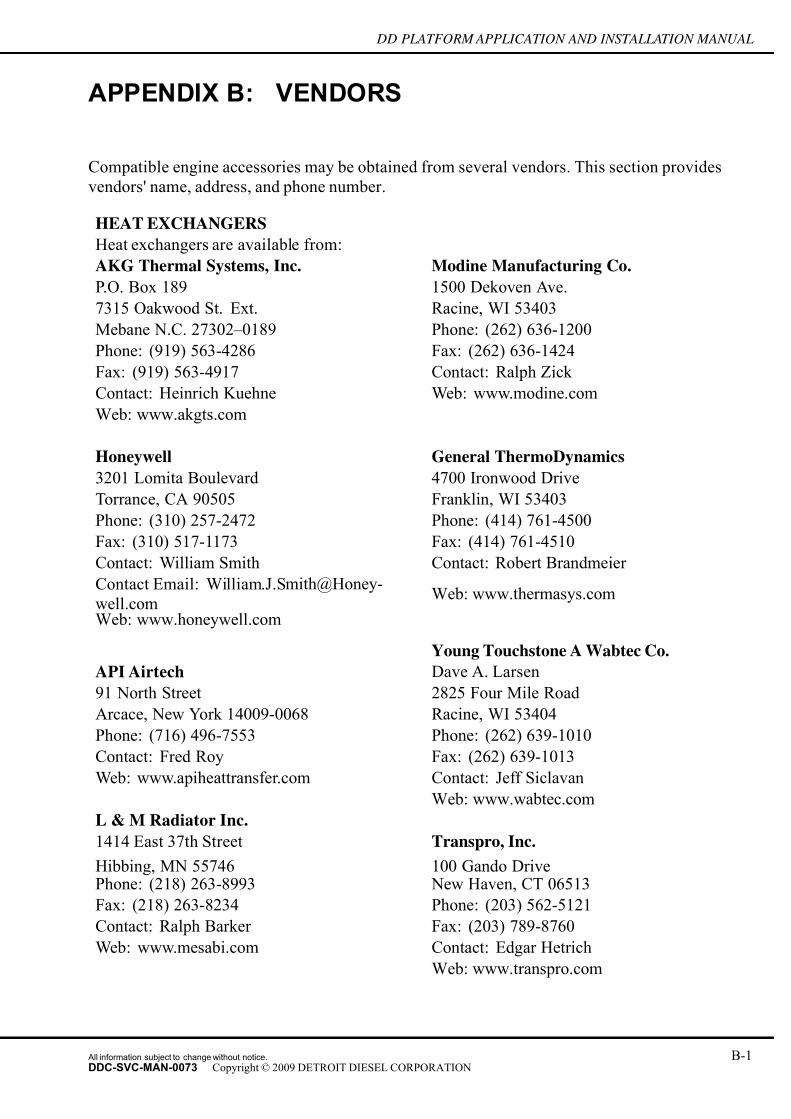
7/14/2019 Dd13-Dd15 a&i Manual
http://slidepdf.com/reader/full/dd13-dd15-ai-manual 297/304
DD PLATFORM APPLICATION AND INSTALLATION MANUAL
APPENDIX B: VENDORS
Compatible engine accessories may be obtained from several vendors. This section provides
vendors' name, address, and phone number.
HEAT EXCHANGERS
Heat exchangers are available from:
AKG Thermal Systems, Inc. Modine Manufacturing Co.
P.O. Box 189 1500 Dekoven Ave.
7315 Oakwood St. Ext. Racine, WI 53403
Mebane N.C. 27302–0189 Phone: (262) 636-1200
Phone: (919) 563-4286 Fax: (262) 636-1424
Fax: (919) 563-4917 Contact: Ralph Zick
Contact: Heinrich Kuehne Web: www.modine.com
Web: www.akgts.com
Honeywell General ThermoDynamics
3201 Lomita Boulevard 4700 Ironwood Drive
Torrance, CA 90505 Franklin, WI 53403
Phone: (310) 257-2472 Phone: (414) 761-4500
Fax: (310) 517-1173 Fax: (414) 761-4510
Contact: William Smith Contact: Robert Brandmeier
Contact Email: William.J.Smith@Honey-
well.comWeb: www.thermasys.com
Web: www.honeywell.com
Young Touchstone A Wabtec Co.
API Airtech Dave A. Larsen
91 North Street 2825 Four Mile Road
Arcace, New York 14009-0068 Racine, WI 53404
Phone: (716) 496-7553 Phone: (262) 639-1010
Contact: Fred Roy Fax: (262) 639-1013
Web: www.apiheattransfer.com Contact: Jeff Siclavan
Web: www.wabtec.com
L & M Radiator Inc.
1414 East 37th Street Transpro, Inc.
Hibbing, MN 55746 100 Gando DrivePhone: (218) 263-8993 New Haven, CT 06513
Fax: (218) 263-8234 Phone: (203) 562-5121
Contact: Ralph Barker Fax: (203) 789-8760
Web: www.mesabi.com Contact: Edgar Hetrich
Web: www.transpro.com
All information subject to change without notice. B-1DDC-SVC-MAN-0073 Copyright © 2009 DETROIT DIESEL CORPORATION

7/14/2019 Dd13-Dd15 a&i Manual
http://slidepdf.com/reader/full/dd13-dd15-ai-manual 298/304
APPENDIX B: VENDORS
AIR STARTERS FAN CLUTCHES
Air starters are available from: Fan clutches are available from:
Ingersoll-Rand Company
Engine Starting Systems
Horton, Inc.
P.O. Box 8000 2565 Walnut Street
Southern Pines, NC 28387 Roseville, MN 55113
Phone: (888) START AIR Phone: (651) 361–6400
Toll free: (800) 621–1320
POW-R-QUIK Fax: (651) 361–6801
5518 Mitchelldale E-mail: [email protected]
Houston, TX 77092 www.hortoninc.com
(713) 683–9546
TDI TurbostartTech Development Inc.
AIR COMPRESSOR
6800 Poe Avenue Air compressors are available from:
P.O. Box 14557 Bendix Commercial Vehicle Systems
Dayton, Ohio 45414–4557 901 Cleveland Street
(513) 898–9600 Elyrua, Ohio 44035
Phone 1–800–AIRBRAKE
Phone: (440) 329–9000
Fax; (440) 329–9557E-mail: [email protected]
www.bendix.com
B-2 All information subject to change without notice.
DDC-SVC-MAN-0073 Copyright © 2009 DETROIT DIESEL CORPORATION

7/14/2019 Dd13-Dd15 a&i Manual
http://slidepdf.com/reader/full/dd13-dd15-ai-manual 299/304
DD PLATFORM APPLICATION AND INSTALLATION MANUAL
GLOSSARY
Aeration Entrainment (progressive or otherwise) of air or
combustion gases in the engine coolant.
Air Bind A condition where a pocket of air has been trapped in
the water pump causing it to lose its prime and abilityto pump coolant.
Air Cleaner A device that prevents airborne particles from entering
air-breathing machinery. The device can be porous paper,
wire mesh filter or oil-bath cleaner.
Afterboil Boiling of the coolant after engine shutdown due to
residual heat in the engine.
Afterboil Volume Quantity of coolant discharged from the pressure relief
over flow tube following engine shutdown.
Aftertreatment Device (ATD) A unit, such as a diesel particulate filter or catalytic
converter, which removes pollutants from the engine
exhaust gasses after the gasses leave the catalyst
combustion chamber.
Air Handling The cooling system's ability to purge air when injected at
a given rate determined by the engine manufacturer and
meeting specified criteria.
Air Recirculation A condition either occurring around the tips of the fan blades or where discharge air from a radiator core is
returned to the front of the core. Either condition hinders
cooling capability.
Air to Boil Temperature(ATB) The ambient tem perature at which engine coolant out
temperature reaches 212°F.
Air to Water Temperature(ATW) The differential between engine coolant out and ambient
temperatures.
Ambient Temperature The envir onmental air temperature in which the unit
operates.
Ash The unburnable solid remains of a fire or oxidation in
diesel soot combustion. This is primarily composed of
Calcium, Zinc, Sulfur, and Phosphorus (usually white to
light gray in color).
All information subject to change without notice. G-1DDC-SVC-MAN-0073 Copyright © 2009 DETROIT DIESEL CORPORATION

7/14/2019 Dd13-Dd15 a&i Manual
http://slidepdf.com/reader/full/dd13-dd15-ai-manual 300/304
GLOSSARY
Automatic (Active) Regeneration A controlled action by the engine system to elevate
the exhaust temperature to the point where soot can be
directly oxidized with O2.
Bleed Line(s) Line(s) strategically placed on the cooling system to vent
air/gases from the system both during fill and engine
running mode. They are also know as deaeration or ventslines.
Blocked Open Thermostat Mechanically blocked open to required position. Used
for cooling tests only.
Blower Fan A fan that pushes the air through the radiator core.
Bottom Tank Temperature Refers to the down stream radiator tank temperature
which is usually the lowest temperature.
Catalyst Any substance which alters the rate of a chemicalreaction, but is not altered or affected by reaction.
Cavitation A localized event where a vapor pressure/temperature
phenomenon of the cooling liquid allows partial
vaporization of the coolant. These cavities of vapor
are carried downstream to a region of higher pressure,
causing them to collapse. Cavitation reduces coolant flow
and increases pump wear.
Cetane Number A relative measure of the time delay between the
beginning of fuel injection and the start of combustion.
Common Powertrain Controller
(CPC)
The CPC will be cab mounted. Provides a direct
connection to cab switches, lamps and data links. The
CPC connects to the engine controller via a CAN.
Monitors and diagnoses all in cab I/O sensors, switches,
actuators. Handles vehicle functions such as cruse
control, vehicle speed limiting, engine speed control
(PTO), progressive shift, and torque limiting.
Controller Area Network (CAN) The CAN is a multicast shared serial bus standard for
connecting the Motor Control Units (MCM).
Coolant A liquid medium used to transport heat from one area
to another.
Cooling Index See Air to Water (ATW) or Air to Boil (ATB) definition.
G-2 All information subject to change without notice.
DDC-SVC-MAN-0073 Copyright © 2009 DETROIT DIESEL CORPORATION
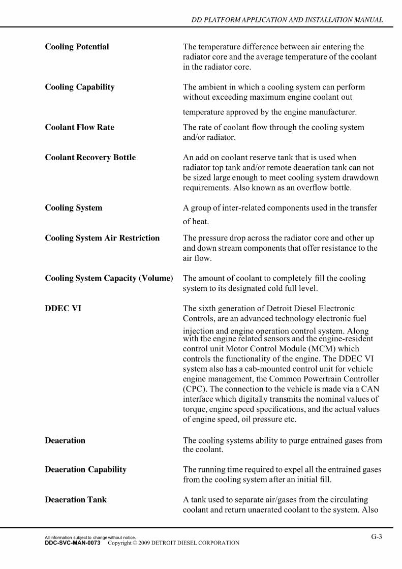
7/14/2019 Dd13-Dd15 a&i Manual
http://slidepdf.com/reader/full/dd13-dd15-ai-manual 301/304
DD PLATFORM APPLICATION AND INSTALLATION MANUAL
Cooling Potential The temperature difference between air entering the
radiator core and the average temperature of the coolant
in the radiator core.
Cooling Capability The ambient in which a cooling system can perform
without exceeding maximum engine coolant out
temperature approved by the engine manufacturer.
Coolant Flow Rate The rate of coolant flow through the cooling system
and/or radiator.
Coolant Recovery Bottle An add on coolant reserve tank that is used when
radiator top tank and/or remote deaeration tank can not
be sized large enough to meet cooling system drawdown
requirements. Also known as an over flow bottle.
Cooling System A group of inter-related components used in the transfer
of heat.
Cooling System Air Restriction The pressure drop across the radiator core and other up
and down stream components that offer resistance to the
air flow.
Cooling System Capacity (Volume) The amount of coolant to completely fill the cooling
system to its designated cold full level.
DDEC VI The sixth generation of Detroit Diesel Electronic
Controls, are an advanced technology electronic fuel
injection and engine operation control system. Alongwith the engine related sensors and the engine-resident
control unit Motor Control Module (MCM) which
controls the functionality of the engine. The DDEC VI
system also has a cab-mounted control unit for vehicle
engine management, the Common Powertrain Controller
(CPC). The connection to the vehicle is made via a CAN
interface which digitally transmits the nominal values of
torque, engine speed specifications, and the actual values
of engine speed, oil pressure etc.
Deaeration The cooling systems ability to purge entrained gases fromthe coolant.
Deaeration Capability The running time required to expel all the entrained gases
from the cooling system after an initial fill.
Deaeration Tank A tank used to separate air/gases from the circulating
coolant and return unaerated coolant to the system. Also
All information subject to change without notice. G-3DDC-SVC-MAN-0073 Copyright © 2009 DETROIT DIESEL CORPORATION

7/14/2019 Dd13-Dd15 a&i Manual
http://slidepdf.com/reader/full/dd13-dd15-ai-manual 302/304
GLOSSARY
used for filling, expansion of the coolant, reserve capacity,
etc. Sometimes called a surge tank or top tank.
Deaeration Volume The volume of space designed into the deaeration tank
and located above the expansion volume for collecting
the entrained gases as it is expelled into the tank.
Derate Reducing engine torque from normal levels.
Diesel Oxiation Catalyst A catalyst that will oxidize CO to CO2, HC to CO
2and
H2O and NO to NO
2.
Diesel Particulate Filter (DPF) A diesel particulate filter (DPF) is a device installed on a
diesel engine system which traps particulate matter (PM)
from the exhaust gas flow. The filter forces the exhaust
gasses through porous cell walls of a core comprised of
ceramic material.
Drawdown The quantity of coolant which can be removed from a full
cooling system before aeration occur s.
Engine Coolant Out Temperature Usually the hottest coolant and measured at the thermostat
housing. Also called radiator inlet or top tank temperature.
Expansion Volume The volume of space designed into the deaeration tank to
permit the coolant to expand as it is heated without being
lost to the environment.
Fan Air Flow The rate of air flow that a fan can deliver at a given speedand static pressure.
Fill Line Used to rout coolant f rom the deaeration tank to the inlet
of the water pump. It is also called a shunt or make up
line.
Fill Rate The coolant flow rate at which an empty cooling system
can be completely filled without over flowing.
Heat Dissipation The amount of heat energy (Btu) that a heat transfer
component can dissipate to the environment at specifiedconditions.
Motor Control Module (MCM) The MCM is designed to support the high voltage,
multi-pulse, duel solenoid fuel systems. The MCM
monitors all engine sensors, determines injection fuelling
(position and duration), performs low speed and high
speed governing, controls after-treatment systems,
G-4 All information subject to change without notice.
DDC-SVC-MAN-0073 Copyright © 2009 DETROIT DIESEL CORPORATION

7/14/2019 Dd13-Dd15 a&i Manual
http://slidepdf.com/reader/full/dd13-dd15-ai-manual 303/304
DD PLATFORM APPLICATION AND INSTALLATION MANUAL
controls the starter, engine brakes, fan and diagnostics
including emissions related diagnostics.
Overcooling A condition where the coolant temperature will not
approach the start to open temperature value of the
thermostat under normal engine operation.
Overheating A condition where the coolant temperature exceeds
allowable limits.
Oxidation A chemical reaction which changes an element from
a lower to higher oxidation state, usually created by a
combination with oxygen atoms.
Particulate Matter (PM) Particles that are formed when diesel engines have
an incomplete fuel combustion. These particles are
composed of sulfate particles, elemental carbon and
Soluble Organic Fractions (SOF) which includes heavyhydrocarbons.
Passive Regeneration Oxidation of soot with NO2.
Radiator Shutters A device placed either in front of or behind the radiator
to block air flow when not required.
Ram Air Flow Air flow through the radiator core due to the motion of
the vehicle or wind.
Ramp Down Similar to a derate, often in conjunction with animpending engine shut down.
Reserve Volume A volume designed into the deaeration tank to provide a
surplus of coolant to offset losses that might occur.
Soot A dark powdery deposit of unburned fuel residues, usually
composed mainly of amorphous carbon, that accumulates
in exhaust systems and other surfaces exposed to smoke
especially fr om the combustion of carbon-rich organic
fuels in the lack of suf ficient oxygen.
Stabilization A condition where under a controlled operating
environment the coolant, oil, air and exhaust temperatures
will not change regardless of the length of time the unit
is run.
All information subject to change without notice. G-5DDC-SVC-MAN-0073 Copyright © 2009 DETROIT DIESEL CORPORATION

7/14/2019 Dd13-Dd15 a&i Manual
http://slidepdf.com/reader/full/dd13-dd15-ai-manual 304/304
GLOSSARY