DCU 305 R3 & R3 LT Users Manual - MSHS Group 305 R3 … · Content Document information 2...
20
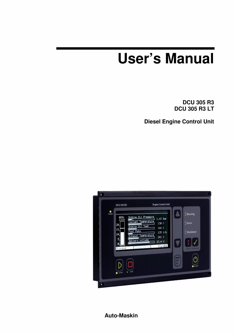
Auto-Maskin User’s Manual DCU 305 R3 DCU 305 R3 LT Diesel Engine Control Unit
Transcript of DCU 305 R3 & R3 LT Users Manual - MSHS Group 305 R3 … · Content Document information 2...
Auto-Maskin
User’s Manual
DCU 305 R3 DCU 305 R3 LT
Diesel Engine Control Unit
Content
Document information 2
Introduction 3
ABOUT THIS MANUAL 3
ABOUT THE DCU 305 R3 & R3 LT 3
CERTIFICATES 4
TECHNICAL SPECIFICATIONS 5
Using the DCU 305 R3 6
THE DIFFERENT VIEWS 6
THE MENU OPTIONS 11
THE BUILT-IN ALARMS 13
FRONTPANEL BUTTONS 14
Communication 17
PROTOCOL AND PIN-CONFIGURATION 17
MULTIDROP COMMUNICATION 18
RETRIEVE THE LOG TO A PC 19
Page 2 (20)
Document information
Document revisions
Revision Update
August 2005
July 2014
Created
R3 L3 included
Copyright © Auto-Maskin AS, 2014
Information given in this document may change without prior notice. This document should
not be copied without written permission from Auto-Maskin.
Title: DCU 305 R3 & R3 LT User's Manual
This Revision: July 2014
All trademarks acknowledged.
Related articles
� DCU 305 R3 & R3 LT Communication Manual.
� DCU 305 R3 & R3 LT Installation Manual.
� Rudolf R3 User’s Manual, English
� Rudolf R3 Configuration Software.
Page 3 (20)
Introduction
About this manual This manual has been published primarily for professionals and qualified
personnel. A person using this material is assumed to have basic
knowledge in marine systems, and be able to carry out related electrical
work.
Work on the boats low-tension circuit should only be carried out by
qualified and experienced persons. Installation or work on the shore
power equipment must only be carried out by electricians authorised to
work with such installations.
It is the sole responsibility of the installer to ensure that the installation
work is carried out in a satisfactorily manner, that it is operationally in
good order, that the approved material and accessories are used and that
the installation meet all applicable rules and regulations.
Note: Auto-Maskin continuously upgrades its products and reserves the
right to make changes and improvements without prior notice.
All information in this manual is based upon information at the time of
printing.
For updated information, please contact your dealer or Auto-Maskin
directly.
Assumptions
This document describes the DCU 305 R3. The unit can be used in
Auxiliary or Propulsion installations.
The unit will be referred to as the Control Unit.
When referring to voltages, always assume DC-voltages. When referring
to AC-voltages it will be mentioned explicit.
About the DCU 305 R3 & R3 LT The DCU 305 R3 is an electronic control unit for control and monitoring
of diesel engines used as propulsion engines or gensets.
Switches and senders from the engines are connected to the control unit
on the wire terminal card RK-66.
Each project is unique, which is why the DCU 305 R3 is customised
using a configuration tool for Windows®, the Rudolf R3 software.
Page 4 (20)
Different expansion cards exist to further enhance the possibilities and
flexibility.
Communication is built-in and ready for use towards slave panels on the
bridge.
The DCU 305 R3 LT is identical to the DCU 305 R3 with the exception
that the LT version do not have the CAN capability.
Certificates The DCU 305 R3 is classified by the following classification societies.
Classification Society
Det norske Veritas, DnV
Lloyd’s Register of Shipping, LR
Germanischer Lloyds, GL
Bureau Veritas, BV
Russian Maritime Register of Shipping, RS
Registro Italiano Navale, RINA
American Bureau of Shipping, ABS
China Classification Society
Other certificates and approvals may exist.
Please see www.auto-maskin.com for latest update.
Page 5 (20)
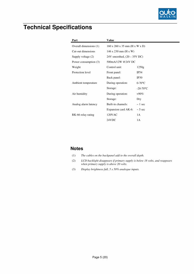
Technical Specifications
Part Value
Overall dimensions (1) 160 x 260 x 35 mm (H x W x D)
Cut-out dimensions 146 x 230 mm (H x W)
Supply voltage (2) 24V smoothed, (20 – 35V DC)
Power consumption (3) 500mA/12W @24V DC
Weight Control unit: 1250g
Protection level Front panel:
Back panel:
IP54
IP30
Ambient temperature During operation:
Storage:
0-70°C
-20-70°C
Air humidity During operation:
Storage:
<90%
Dry
Analog alarm latency Built-in channels:
Expansion card AK-6:
~ 1 sec
~ 5 sec
RK-66 relay rating
120VAC
24VDC
1A
1A
Notes
(1) The cables on the backpanel add to the overall depth.
(2) LCD backlight disappears if primary supply is below 18 volts, and reappears
when primary supply is above 20 volts.
(3) Display brightness full, 5 x 50% analogue inputs.
Page 6 (20)
Using the DCU 305 R3
The different views The DCU 305 R3 has several screens or views.
These are:
� Menu view
� Instrument view
� Alarm list view
� Information view
� Event Log view
� CAN status/restart view.
� Diagnostic display view
Menu
To enter menu view, press the menu button.
� From the instrument view (main view) press menu button once to
access the menu.
� From all other views, press the menu button once to exit to
instrument view, then one more time to enter menu view.
Note: Green light in the menu button indicates that menu view is
entered.
Page 7 (20)
MENU
> INFORMATION
EVENT LOG
LAMP TEST
CONTRAST INCREASE
CONTRAST DECREASE
LOCAL MODE
RPM TEST
CAN STATUS/RESTART
SERVICE DONE
DIAGNOSTIC DISPLAY
EXIT
Table for DCU 305 R3 menu view – cursor at INFO view.
To enter the different views available from the menu, use the up- or down
arrow button to place the cursor in front of the desired view, press menu
button to select.
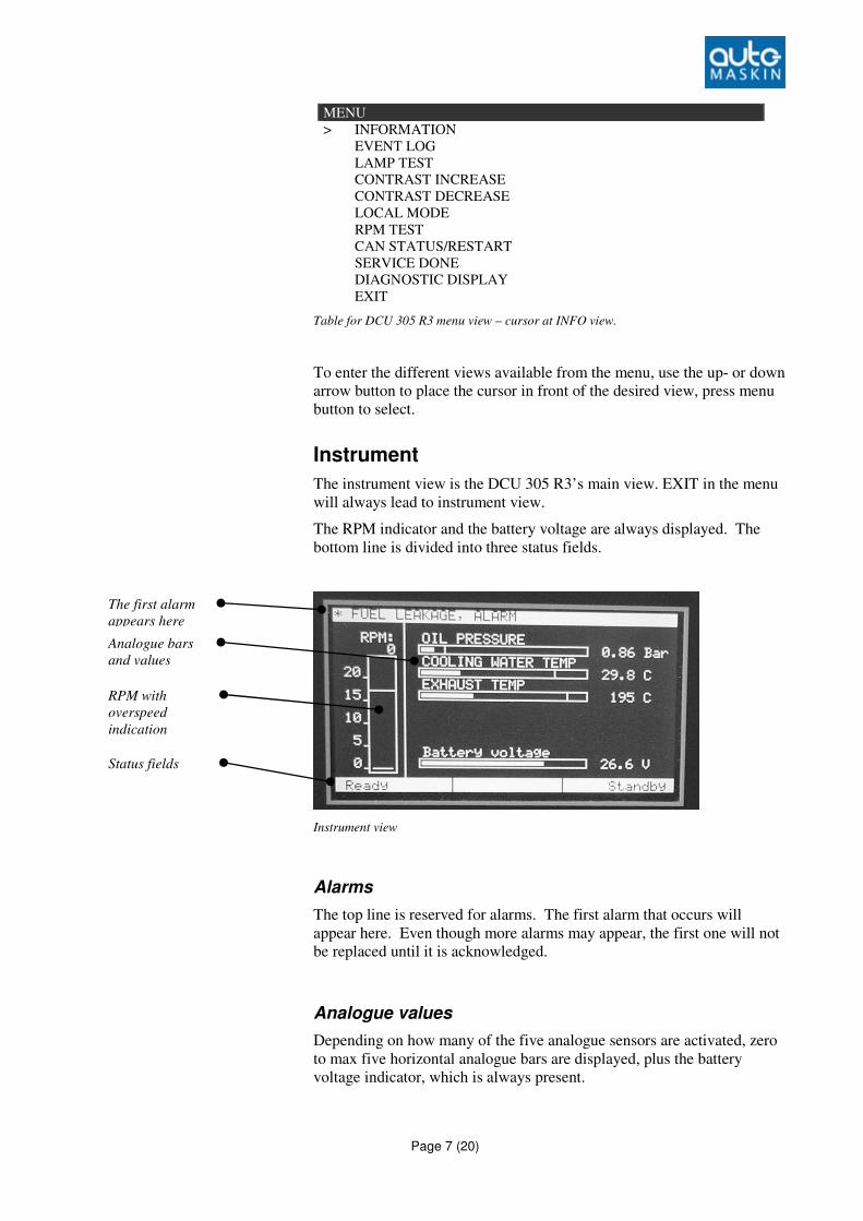
Instrument
The instrument view is the DCU 305 R3’s main view. EXIT in the menu
will always lead to instrument view.
The RPM indicator and the battery voltage are always displayed. The
bottom line is divided into three status fields.
Instrument view
Alarms
The top line is reserved for alarms. The first alarm that occurs will
appear here. Even though more alarms may appear, the first one will not
be replaced until it is acknowledged.
Analogue values
Depending on how many of the five analogue sensors are activated, zero
to max five horizontal analogue bars are displayed, plus the battery
voltage indicator, which is always present.
RPM with
overspeed
indication
Status fields
Analogue bars
and values
The first alarm
appears here
Page 8 (20)
If the optional analogue card AK-6 is used, pressing the down arrow
button will reveal the next six channels.
RPM indicator
To the left of the screen is the speed indicator bar, with the actual RPM
showing at the top of the bar. The overspeed setpoint is marked with a
double horizontal line.
Status fields
The bottom line of the screen is divided into three fields.
� The leftmost field gives engine status such as “Cranking”,
“Running”, “Stopping”, etc.
� The middle field gives signals such as “Start command”,
“Delayed stop”, etc.
� The rightmost field gives info such as “Manual”, “Standby”, etc.
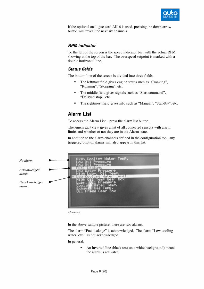
Alarm List
To access the Alarm List – press the alarm list button.
The Alarm List view gives a list of all connected sensors with alarm
limits and whether or not they are in the Alarm state.
In addition to the alarm-channels defined in the configuration tool, any
triggered built-in alarms will also appear in this list.
Alarm list
In the above sample picture, there are two alarms.
The alarm “Fuel leakage” is acknowledged. The alarm “Low cooling
water level” is not acknowledged.
In general:
� An inverted line (black text on a white background) means
the alarm is activated.
Acknowledged
alarm
Unacknowledged
alarm
No alarm
Page 9 (20)
� The toggling asterisk and plus sign (*/+) in front of a line
means the alarm is activated and not yet acknowledged.
Note: In the Alarm list view, pressing the Acknowledge button will
acknowledge all the alarms simultaneously.
Press the menu-button once to exit the Alarm List.
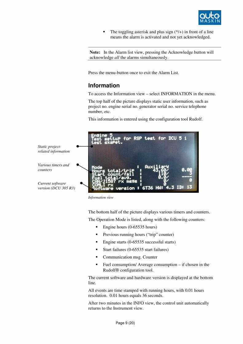
Information
To access the Information view – select INFORMATION in the menu.
The top half of the picture displays static user information, such as
project no. engine serial no. generator serial no. service telephone
number, etc.
This information is entered using the configuration tool Rudolf.
Information view
The bottom half of the picture displays various timers and counters.
The Operation Mode is listed, along with the following counters:
� Engine hours (0-65535 hours)
� Previous running hours (“trip” counter)
� Engine starts (0-65535 successful starts)
� Start failures (0-65535 start failures)
� Communication msg. Counter
� Fuel consumption/ Average consumption – if chosen in the
Rudolf configuration tool.
The current software and hardware version is displayed at the bottom
line.
All events are time stamped with running hours, with 0.01 hours
resolution. 0.01 hours equals 36 seconds.
After two minutes in the INFO view, the control unit automatically
returns to the Instrument view.
Static project-
related information
Various timers and
counters
Current software
version (DCU 305 R3)
Page 10 (20)
Press the menu-button once to exit the Information view.
Event Log
To access the Event Log – Select EVENT LOG in the menu.
All alarms and most events are time stamped with the running hour
meter, and stored internally. The log cannot be erased by the user.
� The logbook stores ~500 events. After the ~500th event, the
oldest event will disappear.
� The last configuration (or change of configuration) will not be
erased.
� To view the log, press the menu-button. For button explanation,
see page 14.
� View the log as you read a logbook: The last occurrence is at the
bottom of the screen.
� To view earlier (older) events, press the Up arrow (�) and to
view newer events, press the Down arrow (�).
Press the menu-button once to exit the Event Log.
CAN Status/Restart
Used for debugging only.
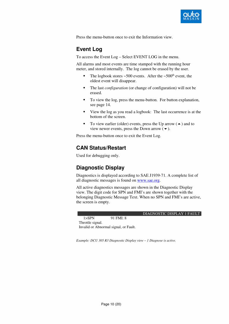
Diagnostic Display
Diagnostics is displayed according to SAE J1939-71. A complete list of
all diagnostic messages is found on www.sae.org.
All active diagnostics messages are shown in the Diagnostic Display
view. The digit code for SPN and FMI’s are shown together with the
belonging Diagnostic Message Text. When no SPN and FMI’s are active,
the screen is empty.
DIAGNOSTIC DISPLAY 1 FAULT
1>SPN 91 FMI: 8
Throttle signal.
Invalid or Abnormal signal, or Fault.
Example: DCU 305 R3 Diagnostic Display view – 1 Diagnose is active.
Page 11 (20)
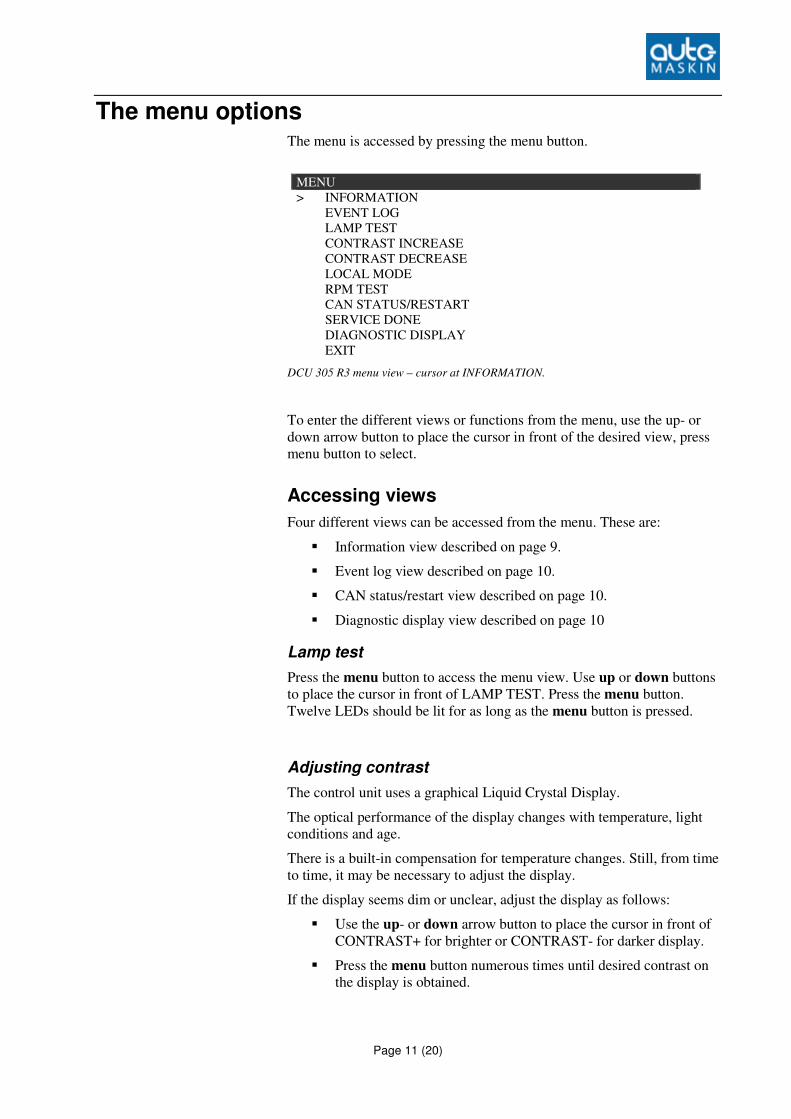
The menu options The menu is accessed by pressing the menu button.
MENU
> INFORMATION
EVENT LOG
LAMP TEST
CONTRAST INCREASE
CONTRAST DECREASE
LOCAL MODE
RPM TEST
CAN STATUS/RESTART
SERVICE DONE
DIAGNOSTIC DISPLAY
EXIT
DCU 305 R3 menu view – cursor at INFORMATION.
To enter the different views or functions from the menu, use the up- or
down arrow button to place the cursor in front of the desired view, press
menu button to select.
Accessing views
Four different views can be accessed from the menu. These are:
� Information view described on page 9.
� Event log view described on page 10.
� CAN status/restart view described on page 10.
� Diagnostic display view described on page 10
Lamp test
Press the menu button to access the menu view. Use up or down buttons
to place the cursor in front of LAMP TEST. Press the menu button.
Twelve LEDs should be lit for as long as the menu button is pressed.
Adjusting contrast
The control unit uses a graphical Liquid Crystal Display.
The optical performance of the display changes with temperature, light
conditions and age.
There is a built-in compensation for temperature changes. Still, from time
to time, it may be necessary to adjust the display.
If the display seems dim or unclear, adjust the display as follows:
� Use the up- or down arrow button to place the cursor in front of
CONTRAST+ for brighter or CONTRAST- for darker display.
� Press the menu button numerous times until desired contrast on
the display is obtained.
Page 12 (20)
The new setting is automatically stored in internal memory, and stays
resident regardless of future power loss.
Note: To preserve LCD lifetime, the display automatically shuts off
after the configured amount of time, if no action has been observed in
that period.
The display turns on again at any keypress, or if an event occurs in the
system, for instance an alarm.
Local mode
It is possible to set the control panel in LOCAL mode. In this mode, none
of the remote commands such as start, stop, reset, etc. will work, neither
on communication, nor on terminal inputs.
� To access LOCAL mode, first enter menu view, and then press
the up- or down button until the cursor is placed in front of
LOCAL MODE.
� Press the menu button to activate local mode.
The unit is now in LOCAL mode and the bottom right status field in the
main view will indicate "LOCAL".
To leave LOCAL mode, repeat the above button sequence.
Page 13 (20)
RPM Test
This section describes how to enter the RPM-test mode. In test mode, the
Overspeed Setpoint (typically 1725 rpm) is reduced to Nominal Setpoint
(typically 1500 rpm).
From the menu view, follow these steps to enter the RPM-test mode:
� Use the up- or down arrow-button to place the cursor in front of
RPM TEST
� Press the menu button once to activate RPM test
The Overspeed Setpoint is now reduced to the Nominal Setpoint. The
bottom left status field displays “RPM TEST ” to indicate and remind of
this.
Note: The test automatically times out after 4 minutes.
It is not possible to enter the RPM TEST mode unless the control unit is
in the Ready state.
Service Done
Several service intervals can be activated by using the Rudolf R3
configuration tool. The Service Done feature resets the service interval
warning.
Note: Refer to the Rudolf User’s manual for more information about
on how to use the service intervals function.
The Built-in Alarms The control unit has a number of internal alarms. These are always
displayed in the language selected by Rudolf.
The following is a list of the most important built-in alarms.
Alarm text Comment
Low battery voltage Low voltage at the start battery.
The alarm is interlocked during starting (cranking) and
stopping.
Secondary battery low
voltage
Low voltage at the secondary battery source.
Overspeed Engine running faster than the overspeed setpoint.
Engine Stopped Engine stopped for no known reason.
Engine failed to stop 60 seconds after issuing the stop command, the engine has
still not stopped.
Start Failure Engine failed to start after the last automatic start attempt.
Pickup failure Unable to read the pickup signal while engine is running.
Page 14 (20)
Alarm text Comment
Output circuit overload Short circuit in one of the +24V outputs terminals 41-44.
The outputs are secured with a fuse that makes an automatic
reset. Remove the overload to correct the problem.
Analogue sensor failure [7] Detailed information on which analog channel that is below
2mA. Here channel 7.
Broken wire [T7 T9] Detailed information on which terminal experiences the
broken wire. Here terminals 7 and 9.
Frontpanel Buttons
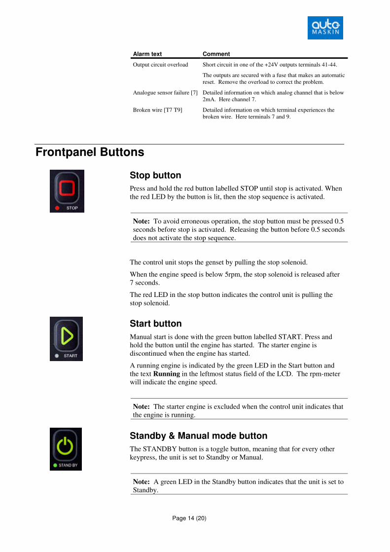
Stop button
Press and hold the red button labelled STOP until stop is activated. When
the red LED by the button is lit, then the stop sequence is activated.
Note: To avoid erroneous operation, the stop button must be pressed 0.5
seconds before stop is activated. Releasing the button before 0.5 seconds
does not activate the stop sequence.
The control unit stops the genset by pulling the stop solenoid.
When the engine speed is below 5rpm, the stop solenoid is released after
7 seconds.
The red LED in the stop button indicates the control unit is pulling the
stop solenoid.
Start button
Manual start is done with the green button labelled START. Press and
hold the button until the engine has started. The starter engine is
discontinued when the engine has started.
A running engine is indicated by the green LED in the Start button and
the text Running in the leftmost status field of the LCD. The rpm-meter
will indicate the engine speed.
Note: The starter engine is excluded when the control unit indicates that
the engine is running.
Standby & Manual mode button
The STANDBY button is a toggle button, meaning that for every other
keypress, the unit is set to Standby or Manual.
Note: A green LED in the Standby button indicates that the unit is set to
Standby.
Page 15 (20)
The rightmost Status field also indicates the chosen mode by displaying
either “Standby” or ”Manual”.
Standby mode
� The control unit will initiate the automatic start sequence when
receiving the Blackout Signal on terminal 34.
� It starts the engine (with the number of start attempts configured)
and then waits for the Delayed Stop signal to initiate automatic
stop.
Manual mode
� The control unit will not automatically start the genset when
receiving the Blackout Signal on terminal 34.
Note: Manual Start and Stop is always possible using the Start and Stop
buttons directly, regardless of Standby and Manual mode settings.
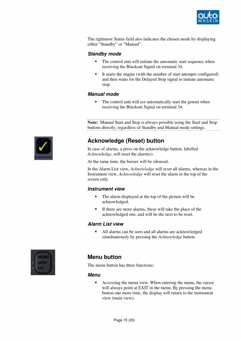
Acknowledge (Reset) button
In case of alarms, a press on the acknowledge button, labelled
Acknowledge, will reset the alarm(s).
At the same time, the buzzer will be silenced.
In the Alarm List view, Acknowledge will reset all alarms, whereas in the
Instrument view, Acknowledge will reset the alarm in the top of the
screen only.
Instrument view
� The alarm displayed at the top of the picture will be
acknowledged.
� If there are more alarms, these will take the place of the
acknowledged one, and will be the next to be reset.
Alarm List view
� All alarms can be seen and all alarms are acknowledged
simultaneously by pressing the Acknowledge button.
Menu button
The menu button has three functions:
Menu
� Accessing the menu view. When entering the menu, the cursor
will always point at EXIT in the menu. By pressing the menu
button one more time, the display will return to the instrument
view (main view).
Page 16 (20)
Enter
� When green light in the menu button is lit, it is possible to select
the different options in the menu.
Exit
� A yellow light is lit in the menu button when the display shows
info view, event log view or alarm list view. When pressing the
menu button the display will escape to instrument view (main
view)
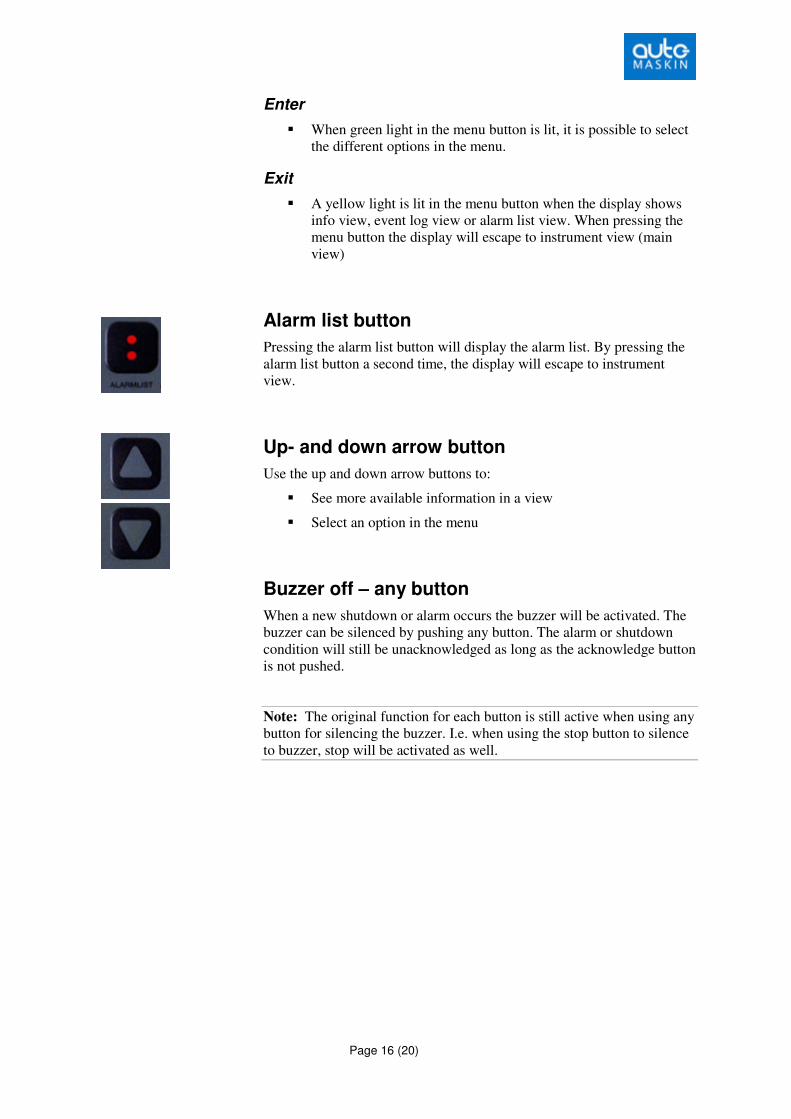
Alarm list button
Pressing the alarm list button will display the alarm list. By pressing the
alarm list button a second time, the display will escape to instrument
view.
Up- and down arrow button
Use the up and down arrow buttons to:
� See more available information in a view
� Select an option in the menu
Buzzer off – any button
When a new shutdown or alarm occurs the buzzer will be activated. The
buzzer can be silenced by pushing any button. The alarm or shutdown
condition will still be unacknowledged as long as the acknowledge button
is not pushed.
Note: The original function for each button is still active when using any
button for silencing the buzzer. I.e. when using the stop button to silence
to buzzer, stop will be activated as well.
Page 17 (20)
Communication
The information from sensors and switches connected to the
DCU 305 R3 can be remotely monitored by utilising the built-in
communication channel.
Any common supervision systems like Factory Link®, InTouch®, etc.
that supports the Comli or Modbus protocol can be used.
The DCU 305 R3 supports the CAN J1939 standard for interface between
Engine ECM and DCU 305.
When connected, all data available on the DCU 305 R3 display is
available in the supervision system. In addition, commands such as Start,
Stop and Acknowledge can be done.
Protocol and pin-configuration The DCU 305 R3 has the Comli and modbus communication protocol
built-in. It communicates at 9600 baud on its RS232 communication
port, P3.
In order to communicate, the control units ID-number must be known.
This ID-number may be any number in the range 1-239. The printout
documentation from Rudolf includes the ID-number. The ID-number is
also displayed in the info view.
The document DCU 305 R3 Communication Manual includes the
complete list of available signals and their address. Please refer to this
document when communicating towards the control panel.
In addition the DCU 305 R3 has the J1939 CAN-bus communication
protocol built-in. On the DCU 305 R3 port P10 is dedicated to CAN
communication. For further description, please see installation manual
for DCU 305 R3.
Page 18 (20)
Port P3
The DCU 305 R3 has a 9-pin D-SUB male connector at port P3, outlined
as follows:
Pin # Description
2 RxD
3 TxD
4 DTR
5 SG
7 RTS
8 CTS
Port P10:
The DCU 305 R3 has a 9-pin D-SUB male connector at port P10,
outlined as follows:
Pin # Description
2 CAN-L
7 CAN-H
Multidrop communication Several DCU 305 R3 units may be connected together in what is known
as a multidrop network.
For this to work correctly, each of the connected units must have its
unique ID-number in the range 1-239. This is done using the parameter
program Rudolf.
Further, the multidrop net must be an RS-485 net. This means that RS-
232/RS-485 converter units, for instance the ICPCON RS232/RS485
unit, must be connected close to the communication port P3 of each DCU
305 R3 unit.
We recommend using a twisted pair cable with two pairs of at least 0.22
mm2, and capacity lower than 60pF/m.
Please contact your dealer or Auto-Maskin for correct dip setting and
cabling of these units in a network.

Page 19 (20)
Retrieve the log to a PC The built-in event log in the control unit can be retrieved with simple
means.
• Connect the configuration software to the DCU 305 R3 using the
Rudolf cable.
• In the configuration software, select Communication – Retrieve
Log…
Wait while the log is uploaded into the PC.