DCS-2000 manual 12-06-02 - D-Link · 3 D-Link DCS-2100+ Internet Camera Power Adapter Installation...
103
D-Link DCS-2100+ Enhanced 2.4 GHz Wireless Internet Camera Manual Building Networks for People Version 2.0
Transcript of DCS-2000 manual 12-06-02 - D-Link · 3 D-Link DCS-2100+ Internet Camera Power Adapter Installation...

D-Link DCS-2100+ Enhanced 2.4 GHz Wireless
Internet Camera
Manual
Building Networks for People
Version 2.0

2
ContentsContents of Package ............................................................................3Introduction............................................................................................4Features and Benefits ...........................................................................4Connections ..........................................................................................6Hardware Installation .............................................................................8Software Installation ..............................................................................9Installing IP Surveillance Software .......................................................13Testing the DCS-2100+ .......................................................................17Security ...............................................................................................18Using and Configuring the DCS-2100+ with a NAT Router...................19Using the DCS-2100+ with the Internet Browser ..................................25Using IP Surveillance Software ............................................................50 Monitor Program ......................................................................50 Playback Program....................................................................70Firmware Upgrades ............................................................................85Appendix ............................................................................................88
Frequently Asked Questions .....................................................88How to PING Your IP Address ...................................................91Reset and Restore ...................................................................92I/O Connector ...........................................................................93Adjusting the Camera Focus ....................................................94Replacing the Lens ...................................................................95Technical Specifications ...........................................................96
Contacting Technical Support ..............................................................98Time Zone Table ..................................................................................99Warranty and Registration .................................................................101

3
D-Link DCS-2100+ Internet CameraPower AdapterInstallation software and manual on CDQuick Installation GuideCamera StandCategory 5 Ethernet Cable2 Antennas
Note: Using a power supply with a different voltage than the one included with theDCS-2100+ will cause damage and void the warranty for this product.
Minimum System Requirements:
Internet Explorer 5.x or higher Internet Web BrowserCPU: Pentium III, 500 MHz or aboveMemory Size: 64 MBVGA card resolution: 800 x 600 or above
Package Contents
!!!!!!!!!!!!!!!!!!!!!!!!!!!!!!
If any of the above items are missing, please contact your reseller.
!!!!!
!!!!!
!!!!!
!!!!!
!!!!!

4
IntroductionThe D-Link DCS-2100+ Wireless Internet Camera is a powerful surveillancesystem that connects wirelessly to an your 802.11b network. TheDCS-2100+ features enhanced 802.11b and connects wirelessly at up to 22Mbps (Megabits per second). The DCS-2100+ differs from a conventionalPC Camera because the Internet Camera is a standalone system with abuilt-in CPU and Web server, providing a low-cost solution capable of solvingdemanding security and home/office monitoring needs. The Internet Cameracan be accessed remotely, and controlled, from any PC or notebook computerover the Internet from anywhere in the world. Simple installation procedures,along with the built-in Web-based interface offers easy integration to yournetwork environments.
Features and BenefitsThe DCS-2100+ Wireless Internet Camera is a standalone system requiringno additional hardware or software. All that is required is a computer withthe Internet Explorer Web browser (version 5.x or above). Just plug-in thecamera and view the picture from your Internet Camera with a valid IPAddress.
Broad Range of ApplicationsWith today�s high-speed Internet, the Internet Camera provides the idealsolution for live video images over the Intranet and Internet for remotemonitoring. The DCS-2100+ allows remote access from an Internet ExplorerWeb browser for live image viewing and allows the administrator to manageand control the Internet Camera anywhere and any time. Apply the InternetCamera to monitor various objects and places such as homes, offices,banks, hospitals, child-care centers, amusement parks and other varietiesof industrial and public monitoring. The Internet Camera can also be usedfor intruder detection with its motion-detection mode, capture still imagesand video images for archiving and many more applications. The wirelesscapability means you can place the camera where it is inconvenient to installnetwork cables.
Supports a Variety of PlatformsSupporting TCP/IP networking, SMTP e-mail, HTTP and other Internet relatedprotocols, the DCS-2100+ Internet Camera can be integrated easily intoother Internet/Intranet applications because of its standards-based features.

5
Features & Benefits (continued)
Web ConfigurationUsing the Internet Explorer Web browser, administrators can configure andmanage the Internet Camera directly from its own Web page via the Intranet orthe Internet. Up to 20 user names and passwords are permitted, with privilegesettings controlled by the administrator.
Powerful Surveillance and Remote Monitoring UtilityThe powerful IP Surveillance software application assigns an administratorwith a pre-defined user ID and password who can modify the Internet Camerasettings from a remote site via an Intranet or the Internet. Users are allowed tomonitor the image, record the image to a hard drive, and take snapshots.
Connection to External DevicesSupporting auxiliary Input/Output connectors, you can connect the InternetCamera to a variety of external devices such as IR-sensors, switches and alarmrelays. Combined with programmable alarming facilities, you can develop a varietyof security applications that are triggered on alarm-based events. The InternetCamera provides an industry standard in/out external connector for connectivity.

6
Connections
Ethernet Cable ConnectorDC Power Connector
I/O Connector
Reset Button
Antenna Connectors
AntennaTwo antennas are included with the DCS-2100+. These are screwed onto theantenna connectors on the back panel to provide a connection with a wirelessnetwork.Ethernet Cable ConnectorThe Internet Camera�s back panel features an RJ-45 connector for connectionsto 10Base-T Ethernet cabling or 100Base-TX Fast Ethernet cabling. This networkport supports the NWay protocol, allowing the Internet Camera to automaticallydetect or negotiate the transmission speed of the network.
Reset ButtonReset will be initiated when the reset button is pressed once and held until thePower LED flashes through its cycle twice.
A Factory reset is initiated when the reset button is pressed continuously for5 seconds or when the Power LED changes from green to red for 2 cycles.(For example you will see the LED turn to red twice, release the reset buttonwhen the LED turns red the second time). The Power LED will begin toflash indicating that the Internet Camera�s settings are reverting back to thefactory settings, then turn back to green.
The Ethernet cable included with the DCS-2100+ Internet Camerais a Category 5 �straight through� cable. This is the recommendedcable type when the camera is physically connected to a 100 MbpsFast Ethernet network hub or switch.

7
DC Power ConnectorThe DC power input connector is located on the DCS-2100+ Internet Camera�sback panel and is labeled 12VDC with a single socket to supply power to theInternet Camera.
I/O ConnectorThe DCS-2100+ provides a terminal block with two pairs of connectors situatedon the back panel. One pair is for input and the other is for output. The I/Oconnectors provide the physical interface to send and receive digital signals toa variety of external alarm devices. Please refer to the Appendix (Page 93)in this manual for detailed information.
Connections (continued)
Located on the bottom panel of the Internet Camera, the socket is used to con-nect the camera stand to the Internet Camera by attaching the screw head onthe camera stand to the Internet Camera.
Bottom Panel
Socket for stand
Power LEDLED stands for Light-Emitting Diode.
The Power LED is positioned to the right of the Internet Camera lens. As soonas the power adapter is connected to the Internet camera the power LED willflash red and green several times, the DCS-2100+ is conducting a self-test.Upon passing the self-test the LED will turn green to indicate a good connectionto an Ethernet port or red to indicate no connection has been made.
Attachment socket for the Camera Stand

8
Hardware InstallationConnect to an Ethernet NetworkIf you are connecting the DCS-2100+ to awired Ethernet network, connect anEthernet cable to the network cableconnector located on the Internet Camera�sback panel and attach it to the network.
If you are connecting the DCS-2100+ to a802.11b wireless Ethernet network, attachthe two wireless antennas to the antennaconnectors on the back panel of theDCS-2100+.
Attach the external power supply
Attach the external power supply to the DCpower input connector located on theInternet Camera�s back panel (labeled12VDC) and connect it to your wall outlet.
The Internet Camera comes with a camerastand with a swivel ball screw head thatcan be attached to the Internet Camerabottom socket cavity. Attach the camerastand to the Internet Camera and station itfor your application. There are holeslocated in the base of the camera standallowing the Internet Camera to be mountedto the ceiling, or any wall securely.
Attaching the Internet Camera to the Camera Stand
When you have a proper connection, the LED will turn from red to green. Thelight may cycle on and off and your computer may show an intermittent loss ofconnectivity, this is normal until you have configured your Internet Camera.

9
Software InstallationAfter you have successfully completed the hardware installation of theDCS-2100+ Internet Camera, it is necessary to install software to configureand operate the camera. The first step is to run the IP Installer program on theCD. IP Installer allows you to use the Internet Camera with your Internet browser.With the IP Installer program you can enter settings that permit the camera toaccess the Internet directly or through your Ethernet network.After the IP Installer software program is completed, you will have an operatingand controllable Internet Camera. From your Internet Explorer Web browseryou will be able to access the video and sound from the Internet camera. Thecamera has a built-in Web server. This Web server will allow the camera toaccess the Internet without being attached to a computer and permits users toview the video and audio remotely.However, it is necessary to install the IP Surveillance software from theenclosed CD to create a truly powerful monitoring and surveillance system.The following section will detail the installation of the IP Installer and the IPSurveillance software.
Installing the IP Installer programInsert the CD that is included with the DCS-2100+ Internet Camera. TheDCS-2100+ installation menu will start up automatically from the CD. If the CDdoes not startup automatically (the Windows operating system can turn thisfunction off, for example), simply access the CD from Windows and click onthe autorun.exe program to access the installation menu shown below:
Click IP Installer

10
Click Next
Highlight the MAC address and then click on the Wizard button to activate theinstallation Wizard.
IMPORTANT:A hardware reset of the Internet Camera is now required to allow the IP Installerprogram to configure the camera correctly. To accomplish this reset, lightly inserta paper clip (or a similar sized tool) into the reset hole on the back of the camera(see page 6 for the location of the reset button.) The LED on the front of thecamera will begin blinking red and green. When it stops the blinking cyclecontinue to hold in the reset button until a second cycle of blinking red and greenlights indicates a second reset cycle has completed. This will take approximately5-7 seconds.
The IP Installer will now show a MAC address for the DCS-2100+ and an IPaddress. This IP address may not be correct at this step in the installation.
The opening IP Installer screen will appear andshow a MAC address of the DCS-2100+ and anIP Address (which may or may not be correctdepending on what you have your DCS-2100+connected to.) If you have a DHCP* server onyour network, there will be a valid IP Addressdisplayed here.
*A DHCP server is a device that supplies IPAddresses to its clients that are on the samenetwork.
Software Installation (continued)

11
Software Installation (continued)If you have a DHCP server on your network,you will already have a valid IP Address inthese fields.If you do not have a DHCP server on yournetwork fill out your IP Address, Subnetmask, Gateway and at least one DNS IPAddress.If you do not know what to put in thesefields, please contact your SystemAdministrator or your Internet ServiceProvider.
Click Next
Leave the box titled This camera can be found by installer whenever it starts upunchecked to avoid running this install application each time you boot up theDCS-2100+. Check this box if you need to change IP address the next time theDCS-2100+ boots up.
Type in your SSID and Connection type con-sistent with your network. (If you areunsure, please contact your networkadministrator).
Choose the Channel that is the same as yourother wireless devices that you would like toconnect to.
You can enable Encryption here (up to 256-bit).
Click Next
Select Long or Short Preamble. LongPreamble is the default setting. See page31 for a description of Preamble.
You can choose a different transmission rateif you need to restrict the camera�s bandwidth.

12
Click OK and the DCS-2100+ Internet Camera willreboot to accept the settings.
If the IP Installer has not made any modifications tothe settings, it will warn you that the settings wereaccepted but no changes were made.
You should now see the opening IP Installer screen with an IP address assignedto the MAC address of the DCS-2100+.
Click on Exit to close IP Installer.
You have now completed the Setup Wizard and are ready to use yourcamera! You can also continue to the next section to install theIP Surveillance software before you begin to use the DCS-2100+.
Software Installation (continued)If you need to make any changes,click Back to modify your camerasettings. To accept the settings,click Restart.
Click Restart

13
Click Next
Real-time MonitoringVideo Recording to hard diskHigh quality videoHigh video compression ratioMaximum of 16 cameras with different display layoutsSmart playbackTriggered event browsingFast database searchingConfigurable automated alarmsAccount password protectionScheduled recording for each cameraEmail / FTP video snapshotsAVI file exportMotion detection for each camera
The IP Surveillance software on the CD included with the DCS-2100+ InternetCamera converts the DCS-2100+ into a powerful, yet flexible, surveillancesystem for home or business, with these features:
Installing IP Surveillance Software
To install IP Surveillance, click on the Install IP Surveillance Software onthe CD included with the Internet Camera. The Welcome screen appears:
!!!!!!!!!!!!!!!!!!!!!!!!!!!!!!!!!!!!!!!!!!!!!!!!!!!!!!!!!!!!!!!!!!!!!!

14
Please read the Software Licensing Agreement and click Yes if you agree withthe agreement. Click No to exit the installation.
Enter your name and company information and click Next.
Click Next
Installing IP Surveillance Software (continued)
Click Yes
15
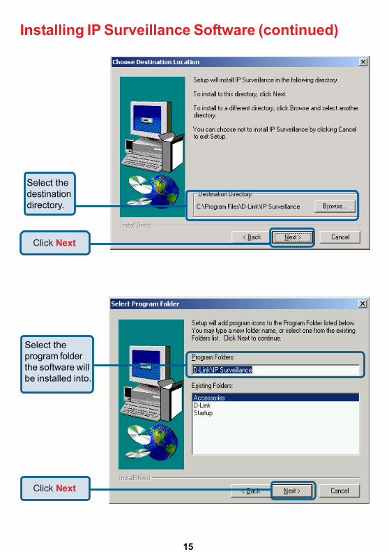
Installing IP Surveillance Software (continued)
Click Next
Click Next
Select thedestinationdirectory.
Select theprogram folderthe software willbe installed into.

16
The installation is complete.
Click Finish
Installing IP Surveillance Software (continued)
Click Next

17
Testing the DCS-2100+ InternetCamera
The window in the center of your browser is the camera image window. Youshould now see a video image and hear the audio over your computer speakersfrom the DCS-2100+. If you are having problems please consult the FAQ sec-tion of this manual.
Open your Internet browserand type in the IP addressof the DCS-2100+. In thisexample the address is:http://192.168.0.146(your DCS-2100+ may havea different IP address basedon what you used in the IPInstaller program.)
18
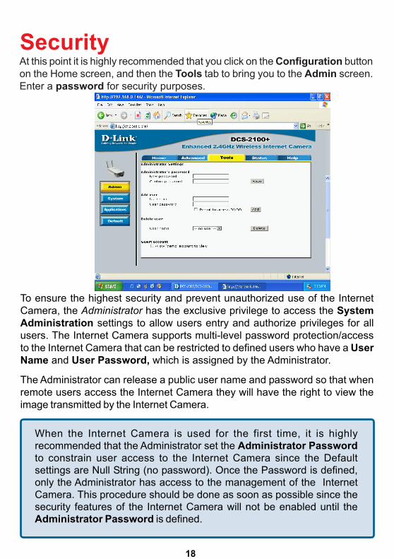
When the Internet Camera is used for the first time, it is highlyrecommended that the Administrator set the Administrator Passwordto constrain user access to the Internet Camera since the Defaultsettings are Null String (no password). Once the Password is defined,only the Administrator has access to the management of the InternetCamera. This procedure should be done as soon as possible since thesecurity features of the Internet Camera will not be enabled until theAdministrator Password is defined.
To ensure the highest security and prevent unauthorized use of the InternetCamera, the Administrator has the exclusive privilege to access the SystemAdministration settings to allow users entry and authorize privileges for allusers. The Internet Camera supports multi-level password protection/accessto the Internet Camera that can be restricted to defined users who have a UserName and User Password, which is assigned by the Administrator.
The Administrator can release a public user name and password so that whenremote users access the Internet Camera they will have the right to view theimage transmitted by the Internet Camera.
At this point it is highly recommended that you click on the Configuration buttonon the Home screen, and then the Tools tab to bring you to the Admin screen.Enter a password for security purposes.
Security

19
Using & Configuring the DCS-2100+with a NAT RouterD-Link�s DCS-2100+ is a versatile and cost effective Internet Camera offeringboth video and audio monitoring. It can also serve as a powerful surveillancesystem in security applications. The DCS-2100+ can be used with any wiredor 802.11b wireless router. This section explains how to view the camera fromeither the Internet or from inside your internal network.
Materials Needed:• 1 DCS-2100+ Internet Camera• 1 Ethernet Cable• A Wired or Wireless router such as the D-Link DI-614+ Wireless Router• Ethernet based PC for system configuration
SETTING UP THE DCS-2100+ FOR USE BEHIND A ROUTER
Installing a DCS-2100+ Internet Camera on your network is an easy 4�stepprocedure:""""" Assign a local IP Address to your Internet Camera##### View the Internet Camera Using Your Internet Explorer Web browser$$$$$ Access the Router on Your Web browser%%%%% Open Virtual Server Ports for Your Router (Enable Remote Viewing)
This section is designed to walk you through the setup process for installingyour camera behind a router and enable remote video viewing. For the basicsetup of the DCS-2100+, follow the steps outlined in the Quick InstallationGuide.
After you have completed the setup of the DCS-2100+ outlined in the QuickInstallation Guide you will have an operating camera that has an assigned IPAddress. Because you are using a router to share the Internet with one ormore PCs, the IP Address assigned to the Internet Camera will be a local IPAddress. This allows viewing within your Local Area Network (LAN) until therouter is configured to allow remote viewing of the camera over the Internet.
Run the IP Installer program from the CD included with the DCS-2100+.Follow the steps in the Quick Installation Guide to configure theDCS-2100+. The camera will be assigned a local IP Address that allows itto be recognized by the router. Write down this IP Address for futurereference.
""""" Assign a Local IP Address for Your Camera

20
Using & Configuring the DCS-2100+ with aNAT Router (continued)
Assign a Local IP Address with IP Installer
##### View the Internet Camera using your Internet Explorer Webbrowser
Run your Internet Explorer Web browser. In the address bar, type in the IPAddress that was assigned to the Internet Camera by the IP Installer program.The DCS-2100+ Home Page appears with a window displaying live video fromthe camera. You are able to view this screen from any PC running InternetExplorer on your LAN.
Viewing the Video on the browser to test the connection
Click on the Configuration button on the left side of the display. Scroll to thebottom of the Network Configuration page to display the ports used by HTTPand Streaming audio and video.
This is the IP Addressassigned to your camera.Write it down for later use.192.168.0.146 is only anexample. You will probablyhave a different IP Address.
Click on theConfiguration button.

21
Using & Configuring the DCS-2100+ with aNAT Router (continued)
Ports that are used by the DCS-2100+
Router Set-Up and InstallationThe following steps generally apply to any router that you have on your network.The D-Link DI-614+ is used as an example to clarify the configuration process.Configure the initial settings of the DI-614+ by following the steps outlined in theDI-614+ Quick Installation Guide.
These are the portsettings for your camera.They can be changed ifneeded.
$$$$$ Access Your Router on Your Web Browser
If you have cable or DSL Internet service, you will most likely have a dynamicallyassigned WAN IP Address. �Dynamic� means that your router�s IP address canchange from time to time depending on your ISP. A dynamic WAN IP Addressidentifies your router on the public network and allows it to access the Internet.To find out what your router�s WAN IP Address is, go to the Status menu onyour router and locate the WAN information for your router (as shown on thenext page). The WAN IP Address will be listed. This will be the address thatyou will need to type in your web browser to view your camera over the Internet.

22
http://192.168.0.1
Determine Your Router�s IP Address (WAN)
Note: Because a dynamic WAN IP can change from time to time depending onyour ISP, you may want to obtain a Static IP address from your ISP. A Static IPaddress is a fixed IP address that will not change over time and will be moreconvenient for you to use to access your camera from a remote location. TheStatic IP Address will also allow you to access your camera attached to yourrouter over the Internet
%%%%% Open Virtual Server Ports to Enable Remote Image Viewing
Your WAN IPAddress will belisted here.
Using & Configuring the DCS-2100+ with aNAT Router (continued)
The firewall security features built into the DI-614+ router prevent users fromaccessing the video from the DCS-2100+ over the Internet. The router connectsto the Internet over a series of numbered ports. The ports normally used by theDCS-2100+ are blocked from access over the Internet. Therefore, these portsneed to be made accessible over the Internet. This is accomplished using theVirtual Server function on the DI-614+ router. The Virtual Server ports usedby the camera must be opened through the router for remote access to yourcamera. Virtual Server is accessed by clicking on the Advanced tab of therouter screen.

23
Important: Some ISPs block access to port 80 and other commonly usedInternet ports to conserve bandwidth. Check with your ISP so that you canopen the appropriate ports accordingly. If your ISP does not pass traffic on port80, you will need to change the port the camera uses from 80 to somethingelse, such as 800. Not all routers are the same, so refer to your user manualfor specific instructions on how to open ports.
Using & Configuring the DCS-2100+ with aNAT Router (continued)
Enter valid ports in the VirtualServers section of yourrouter
192.168.0.146
Follow these steps to configure your router�s Virtual Server settings:
Repeat the above steps adding ports 5001, 5002 and 5003 to both thePublic and Private Port sections. A check mark appearing before thecamera name will indicate that the ports are enabled.
• Click Enabled.• Select Both under Protocol Type (TCP and UDP)• Enter your camera�s local IP Address (e.g., 192.168.0.146 in
the example in step ##### above) in the Private IP field.• If you are using the default camera port settings, enter 80 in to
the Public and Private Port section, click Apply.• Scheduling should be set to Always so that the camera images
can be accessed at any time.
24
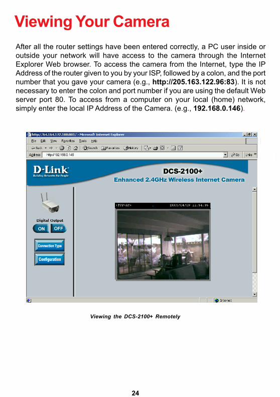
Viewing Your CameraAfter all the router settings have been entered correctly, a PC user inside oroutside your network will have access to the camera through the InternetExplorer Web browser. To access the camera from the Internet, type the IPAddress of the router given to you by your ISP, followed by a colon, and the portnumber that you gave your camera (e.g., http://205.163.122.96:83). It is notnecessary to enter the colon and port number if you are using the default Webserver port 80. To access from a computer on your local (home) network,simply enter the local IP Address of the Camera. (e.g., 192.168.0.146).
Viewing the DCS-2100+ Remotely

25
Open your Internet Explorer Web browser and enter the IP address for yourInternet Camera.In the example, this address is 192.168.0.146. Your address may differ.
If a window appearsasking to install aVerisign certificatefor authenticationClick Yes.
If you are following this manual in the order it is presented, you should now havean operating DCS-2100+ Internet Camera configured with the Installer program.You also have installed the IP Surveillance software from the CD. This sectionof the manual will deal with using the Internet Camera in two parts:
! Using the DCS-2100+ with an Internet browser and accessing the screens to control and monitor the camera.
! Using IP Surveillance software with the DCS-2100+.
Using the DCS-2100+ with anInternet browser

26
Home Page ScreenThe image from the DCS-2100+ should be visible from the Home page on yourcomputer monitor.
Using the DCS-2100+ with an Internet browser(continued)
Click on the Connection Type button to change settings related to theconnection.
There are twobuttons on the leftside of the Homepage:Connection TypeandConfiguration.
Click Connection Type

27
Home > Connection Type Screen
Click the Home tab to return to the DCS-2100+ Home page.
Protocol OptionThe UDP Protocol should be chosen for the most users. Generally, the clientcomputer will automatically try these protocols in the following order, UDP ->TCP -> HTTP. After the client connects to the DCS-2100+ successfully, the working protocolwill be displayed in Protocol Option. The chosen protocol will be recorded inthe user�s PC and used for the next connection. If the network environment ischanged or users want to let the Web browser automatically detect the protocol,select UDP manually and click Save to change the setting and return Home toreconnect with the new setting.
Options:UDP Protocol - Offers the highest image and video quality.However, packet losses will diminish image quality when bandwidthbecomes restricted.TCP Protocol - Packet loss is less likely to occur compared to UDPwhen bandwidth is restricted.HTTP Protocol - If the network is protected by a firewall and it opensHTTP port (80) only, HTTP protocol must be selected. In this mode,audio is disabled and only video can be viewed.
Media Option:Allows a user to disable audio when viewing video.
The following options are available from the Connection Type screen:
Using the DCS-2100+ with an Internet browser(continued)
http://192.168.0.146

28
Home > Configuration
There are 5 tabs across the top of the Configuration screen. From each tab,different elements of the DCS-2100+ can be configured. The Advanced tab isthe default screen in Configuration and Network is the default screen underAdvanced.
Using the DCS-2100+ with an Internet browser(continued)
Any changes made to these settings willrequire the system to restart to validate.Make sure every field is correctly typedbefore clicking on Apply.
Click Configuration

29
Configuration > Advanced > NetworkReset IP Address at next boot
IP address - Necessary for network identification.
Subnet mask - Used to determine if the destination is in the samesubnet. The default value is �255.255.255.0.�
Once the DCS-2100+ is configured, this box should be unchecked at all times.If the box has been checked and the connection is lost, either run IP Installeror PING the IP Address of the camera from a command prompt to regain theconnection.
Default router - The router used to forward frames to destinationsin a different subnet. Invalid router settings maycause the failure of transmissions to a differentsubnet.
Primary DNS - Primary domain name server that translatesnames to IP addresses.
Secondary DNS - Secondary domain name server to backup theprimary one.
General Settings
Using the DCS-2100+ with an Internet browser(continued)
Can be set to other than the default port 80. Whenthe administrator changes the HTTP port of theDCS-2100+ (which has an IP address of192.168.0.100) from 80 to 8080, users must typehttp://192.168.0.100:8080 in the Web browserbar.
HTTP Port-
HTTP Settings

30
Configuration > Advanced >Network Settings (continued)
SSID - (Service Set Identifier) is a name that identifies awireless network. Access Points and wirelessclients attempting to connect to a specific WLAN(Wireless Local Area Network) must use thesame SSID. The default setting is default.
Wireless Mode- Click on the pull-down menu; select from thefollowing options:Infrastructure - connecting the WLAN using anAccess Point such as the DWL-1000AP+. (Thedefault setting.)Ad-Hoc � wireless mode used when connectingdirectly to a computer equipped with a wirelessadapter in a peer-to-peer environment.
Using the DCS-2100+ with an Internet browser(continued)
Streaming SettingsControl channel port - It can be set to other than the default port 5001 to
correspond with the port opened by the firewall.
Audio channel port - It can be set to other than the default port 5002 tocorrespond with the port opened by the firewall.
Video channel port - It can be set to other than the default port 5003 tocorrespond with the port opened by the firewall.
WLAN Configuration Settings
Improve audio qualityin low bandwidthenvironment - In a low bandwidth network environment you can
check this option to improve audio quality bysacrificing some real-time synchronization.

31
Using the DCS-2100+ with an Internet browser(continued)Configuration > Advanced >Network Settings (continued)Channel - The default wireless channel setting is channel
6. Select the channel that is the same as theother wireless devices on your network.
TX Rate- Select the transmission rate on the network.22 Mbps is the default setting.
Preamble- Select Long or Short Preamble. The Preambledefines the length of the CRC block (CyclicRedundancy Check is a common technique fordetecting data transmission errors) forcommunication between the Access Point andthe roaming wireless Network adapters. LongPreamble is the default setting. Note: Highnetwork traffic areas should use the shorterpreamble type.
Data Encryption - Enable Encryption by clicking on the box. TheDCS-2100+ has Encryption disabled as thedefault setting.
Auth mode - Choose one of the following authorizationmodes:
Open Authentication - Communicates the key across the network.Shared Authentication - Allows communication only with other devices
with identical WEP settings.Auto - Will automatically adjust to the Authentication
mode of the wireless client.Key type - Select the key length, either 64, 128 or 256 bits.Key Format - Select an ASCII or hexadecimal key format.Key Index - You can create up to 4 different security keys.
Click Apply to makechanges effective

32
Using the DCS-2100+ with an Internet browser(continued)Configuration > Advanced > Mail & FTPClick the Mail&FTP button from the Configuration screen to access videosettings that control sending images via email and FTP.
SMTPSMTP (mail) server 1 - The domain name or IP address of an external
mail server.
Recipient email address 1 - The email address of recipients for snapshots ora system log file. Multiple recipients must beseparated by a semicolon �;�
SMTP (mail) server 2 -
Return email address -
Recipient email address 2 - The email address of recipients for the secondaryserver.
A return email address to use if the snapshot orsystem log email fails to send.
The domain name or IP address of a secondarymail server used if the primary mail server isunreachable.

33
Using the DCS-2100+ with an Internet browser(continued)Configuration > Advanced > Mail & FTP (Continued)FTP Settings
1st FTP server -
If the DCS-2100+ is located inside a network thatis protected by a firewall, a data connection forFTP may be prohibited. Passive mode FTP canbypass this rule and allow the uploading ofsnapshots. If the passive mode is selected, theDCS-2100+ can automatically attempt to uploadin active mode if the external FTP server doesnot support passive mode.
Granted folder on the external FTP server. Thestring must conform to the external FTP server.Some FTP servers cannot accept a precedingslash symbol before the path if there is no virtualpath mapping. Refer to the instructions of theexternal FTP server for details. The folder privilegemust be open for upload.
1st FTP remote folder -Granted password on the external FTP server.Granted user name on the external FTP server.1st FTP user name -
The domain name or IP address of the externalFTP server. The following user settings must becorrectly configured for remote access.
It can be other than default port 21. If you find thatyou want to change the port to a port numberother than 21, you will need to specify the portwhen connecting to the FTP server. For exampleFTP://68.5.1.81:60 (if you are to use port 60 foryour FTP server port)
Local FTP server port -
1st FTP password -
Primary FTP PassiveMode-

34
Click Apply to makechanges effective
Using the DCS-2100+ with an Internet browser(continued)Configuration > Advanced > Mail & FTP (Continued)
2nd FTP user name - Granted user name on the backup FTP server.
2nd FTP password - Granted password on the backup FTP server.
2nd FTP server - The domain name or IP address of the externalFTP server.
2nd FTP remote folder - Granted folder on the backup FTP server.
Mode - Passive mode setting for the backup FTP server.Secondary FTP passive
Invalid settings may cause the DCS-2100+ to not respond. Change theconfiguration settings only if necessary. Consult with your networkadministrator or your Internet Service Provider (ISP) if you do not have thenecessary information. If you cannot connect to the camera, refer to page92 for camera reset and restore factory settings procedures.

35
Click the Video button from the Configuration screen to access video settingsthat affect how the video image appears.
Configuration > Advanced > Video
Using the DCS-2100+ with an Internet browser(continued)
Click Video
Text on video -
Color -
Size - Three options exist for two sizes of video display:Normal is the default video display mode.Half is a quarter size of Normal.Half x 2 has the same video size as Normal butimage quality is reduced and it consumes lessnetwork bandwidth.
Text will be displayed in the black bar above the videowindow with the timestamp. The timestamp iscaptured from the date and time of the DCS-2100+and is maintained by a built-in real-time clock.
Select the option for color or monochrome videodisplay.

36
Configuration > Advanced > Video (Continued)
Using the DCS-2100+ with an Internet browser(continued)
Maximum frame rate-
Video quality control-
Flip - Vertically rotate the video.
Power line frequency(for fluorescent light)
Fluorescent lights may intermittently flash dependingon the AC power line frequency. Change thefrequency setting to eliminate a flashing image whenthe light source is fluorescent light.
Limits the maximum refresh frame rate. The framerate is used with the Video quality control setting(below) to optimize bandwidth utilization and videoquality.
To fix the bandwidth utilization regardless of the videoquality, choose Fix bit rate and select the desiredbandwidth. The video quality may be reduced inorder to send maximum frames with limitedbandwidth, especially when images changedrastically. For higher video detail regardless of thebandwidth selection, select Fix quality and selecta video quality level. This setting will utilize morebandwidth to send the maximum frames whenimages change drastically.
Mirror - Horizontally rotate the video. Check both flip and mirror if the DCS-2100+ is to be installed upside down.
White balance - Choose the suitable option for the best color temperature.
Click Apply to makechanges effective

37
Recommendations for setting video for the bestperformance:
�Best performance� means the image refresh rate should be the fastest possibleand the video quality should be the best possible at the lowest network bandwidthpossible. Three factors, Maximum frame rate, Fix bit rate, and Fix quality inthe Video Configuration page, are related to performance.
My priority is real-time motion imagesTo achieve a real-time visual effect, the network bandwidth should be largeenough to transmit 20 image frames per second (fps) or more. If you are on abroadband network over 1 Mbps, you can set Fix bit Rate to 1000Kbps or1200Kbps, or set Fix quality to achieve the maximum frames. The maximumframe rate is 25 in 50Hz system and 30 in 60Hz system. If your networkbandwidth is more than 384Kbps, you can adjust Fix bit rate according to yourbandwidth and set the maximum frame rate of 25 to 30.
If the images vary dramatically in your environment, you may slow down themaximum frame rate to 20 to decrease the transmitted data for better videoquality. Since the human eye could not easily differentiate between 20 and 25or 30 frames per second, the slower frame rate will not be noticed. If yournetwork bandwidth is below 384 Kbps, you should adjust the bit rate accordingto your bandwidth and experiment to allow for the best frame rate that can beachieved. The faster frame rate in a slow network will blur the images. You mayalso try to choose Half in size option for better images or Half x 2 for largerimage size. Because the network has burst constraints and everyone�senvironment is not the same, any poor connection will impair normalperformance.
Using the DCS-2100+ with an Internet browser(continued)
My priority is clear identification for each imageTo have the best video quality, you should set Fix quality to detailed or excellentand tune the Maximum frame rate to suit your network bandwidth. If you getsome broken pictures in a slow network, you can set TCP protocol inConnection type for a more accurate transmission but the received imagesmay have a lag. Note that any slow connection with multiple users will impairperformance.

38
Recommendations for setting video for the bestperformance (continued):I want to compromise between real-time and clear imagesIf you have a broadband network, set Fix quality to Good image quality, orhigher, instead of setting the Bit rate. Otherwise, fix the bit rate according toyour actual network speed and set the frame rate to 30. If the image quality islow, select a lower frame rate above 15. If the image quality is still not improved,select a lower bit rate.
Click the Image Settings button from the Configuration screen to access thesettings that affect how the video image appears.
From this screen you can fine tune the video image.
Image Brightness, Contrast, Saturation and Hue are all adjusted in the samemanner. For each video compensation you can set from among eleven levelsranged from -5 to +5. The default setting is zero for each adjustment.
You may press to fine-tune the image and see what affect the settingwill have on the image. When the image is acceptable, press to store theimage settings, or to recall the original settings. If settings are changedwithout saving, they will be used until the next system start-up.
Using the DCS-2100+ with an Internet browser(continued)
Configuration > Advanced > Image Settings
Click Image Settings

39
Configuration > Advanced > Motion Detection
Click the Motion Detection button from the Configuration screen to accesssettings that affect how the DCS-2100+ Internet Camera can serve as a securitydevice by recording only when motion is detected.
Enable motion detection - Check this option to turn on the motion detection.
Window Name - The text entered here will show at the top of thewindow.
Sensitivity - Sets the measurable difference between twosequential images that would indicate motion.
Percentage - Sets the amount of motion in the window beingmonitored that is required to initiate a motiondetected alert.
Using the DCS-2100+ with an Internet browser(continued)
Note: Setting a higher sensitivity and a lowerpercentage makes any motion more easilydetected.
Click Motion Detection
http://192.168.0.146

40
Configuration > Advanced >Motion Detection (continued)
To display motion detection, a graphic bar will rise or fall depending on theimage variation.
A green bar means the image variation is under the monitoring level, and nomotion detection alert is triggered. A red bar means the image variation is overthe monitoring level and a motion detected alert is triggered. When the bargoes red, the window that the motion is detected in will also be outlined in red(note: remember that you can have up to 3 windows selected for motiondetection). You can return to the DCS-2100+ Home Page and the monitoredwindow will not be visible, but the red frame will show on the home page whenmotion is detected.
New - Click to add a new window. A maximum of threewindows can be opened simultaneously. Useyour mouse to drag the window frame to resizeor the title bar to move. Clicking on the �x� at theupper right corner of the window will close thewindow.
Save - Saves the related settings of that window.
Using the DCS-2100+ with an Internet browser(continued)

41
Configuration > Tools > AdminClick on the Tools tab to access 4 utility screens for controlling andadministering the DCS-2100+. The default screen in Tools is the Admin screen.
The DCS-2100+ is manufactured without any passwords by default. This allowsthe ability to access the DCS-2100+ (including the Configuration) by anyone aslong as the IP address is known. It is recommended that you enter a passwordif the DCS-2100+ is intended to be accessed by others.
Type a password in the New Password field to enable protection, and thenconfirm the password in Confirm Password field.
This password is used to identify the administrator. You can add accounts withUser name and User Password for other users in the Add user section.
Using the DCS-2100+ with an Internet browser(continued)
You can provide up to twenty accounts for other users / visitors. Each accountidentifies the access right. This allows multiple visitors to share the same accountof different levels. An option to Permit to access DI/DO (Digital In/Digital Out)is provided for each account. Some users may need to be prohibited fromcontrolling your attached security devices.
42
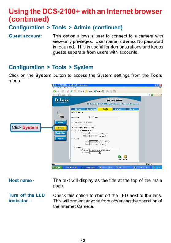
Guest account: This option allows a user to connect to a camera withview-only privileges. User name is demo. No passwordis required. This is useful for demonstrations and keepsguests separate from users with accounts.
Configuration > Tools > SystemClick on the System button to access the System settings from the Toolsmenu.
Host name -
Using the DCS-2100+ with an Internet browser(continued)
Check this option to shut off the LED next to the lens.This will prevent anyone from observing the operation ofthe Internet Camera.
The text will display as the title at the top of the mainpage.
Turn off the LEDindicator -
Click System
Configuration > Tools > Admin (continued)

43
Configuration > Tools > System
Manual - Adjust the date and time according to what isentered by the administrator. Notice the format inthe related field while typing.
Automatic - Synchronize with the NTP server over the Internetwhenever the DCS-2100+ starts up. It will fail ifthe assigned timeserver cannot be reached.
NTP server - Assign the IP address or domain name of thetimeserver. Leaving the text box blank will let theDCS-2100+ connect to default timeservers.
Time zone - Used to adjust the hour of timeservers for localsettings.
Keep current date andtime -
Using the DCS-2100+ with an Internet browser(continued)
Click to save the current date and time ofDCS-2100+. An internal real-time clock maintainsthe date and time even when the power is off.
Sync with computer time-
Click Apply to makechanges effective
Synchronize the date and time of DCS-2100+with the local computer. The date and time of thePC is displayed and updated in the DCS-2100+.

44
Configuration > Tools > Applications
Using the DCS-2100+ with an Internet browser(continued)
Click on the Applications button to access the Applications settings from theTools menu.
http://192.168.0.146

45
Configuration > Tools > Applications (Continued)Weekly schedule:Sunday through Saturday - Select the weekdays that should perform the
following operations:
Snapshots begin at -
Snapshots stop at - Sets the time to stop the operations.
Event operation:
Delay second(s) beforedetecting next event - Sets the time delay before restarting to check the
trigger condition when the current condition istriggered.
Take snapshots atsecond(s) after event - After a snapshot is taken because of a trigger,
another snapshot will be taken after theconfigured time in seconds.
Trigger condition - There are 4 conditions related to the digital inputand three windows for motion detection. Therecan be multiple selections. Select the appropriatedigital input condition according to thecharacteristics of the external device. High or lowindicate external voltage input for level trigger,while rising or falling is for edge trigger. Thereare three windows shown for the name youdefined for motion detection. Undefined willshow instead of the window title if motiondetection is not setup yet.
Reset output - Check and save this option to reset the externaldevice at the digital output back to the originalstate.
Using the DCS-2100+ with an Internet browser(continued)
Set the time to start operations. Setting thebegin time the same as the stop time willforce the operations to run continuously.

46
Configuration > Tools > Applications (Continued)
Trigger action - There are four options for two actions regardingeither trigger condition. They can have multipleselections. While choosing the trigger outputalarm, the digital output will short both pins toconnect the circuit of the attached externaldevice; otherwise both pins will be open. Whilechoosing to upload snapshots, the method canbe either email or FTP. The snapshot names willbe �videopre.jpg�, videotrg.jpg�, and�videopos.jpg� respectively for the snapshotsbefore event, right upon event, and after event.The date and time suffix may be added accordingto the option. Confirm the external mail or FTPserver settings in network configuration.
Sequential operation
Using the DCS-2100+ with an Internet browser(continued)
Snapshot every The camera will send snapshots at the specifiedinterval to the external server according to thechosen method. Remember this operation isdependent to the weekly schedule.
Send snapshots by email - Any upload action specified in the options abovewill use the method chosen here. The capturedsnapshot named �video.jpg� will be attached inthe email with subject �Periodic snapshots.�
Send snapshots by FTP - The captured snapshots will upload to theexternal FTP server with the file name dependingon the next option.
second(s) -

47
Configuration > Tools > Applications (Continued)
Click on the Default button to access the factory Default settings from theTools menu.
Click Apply on the screen to restore the factory default settings. This meansany changes made will be lost and the system will be reset to the initial statuswhen shipped from the factory. After confirmation, the system will restart andrequire the IP Installer software program to setup the DCS-2100+.
Using the DCS-2100+ with an Internet browser(continued)
Click Apply to make changes effective
Configuration > Tools > Default
Click Default
FTP put snapshots withdate and time suffix - If the suffix is added, the captured date and time
can be easily differentiated from the snapshot filename in either sequential or event operation. Forinstance, �[email protected]� meansthe JPEG image was captured at 4 minutes and5 seconds after 3 o�clock, January 2nd, A.D. 2002.If the suffix is omitted, the file named �video.jpg�on the external FTP server will be refreshed atthe specified interval.
http://192.168.0.146

48
The Device Info screen lists the following important settings that are currentlyset for the DCS-2100+
! Firmware Version number! Mac Address! IP Address! Subnet Mask! Default router address! Primary DNS address! Secondary DNS Address
Using the DCS-2100+ with an Internet browser(continued)Configuration > Status > Device InfoClick on the Status tab to access Device Info and a Log of DCS-2100+system activity. The Device Info is the default screen when you click on theStatus tab.
Click Device Info
http://192.168.0.146

49
Click on the Help tab to access descriptions of the particular function youneed help with. The help screen is organized in the order of the tabs and theneach menu item under that tab.
Configuration > Help
Using the DCS-2100+ with an Internet browser(continued)Configuration > Status > Log
Click on the Log button to access a system log of system activity from theStatus menu. The content of the log file reveals useful information about thecurrent configuration and connection logged after the DCS-2100+ boots up.
Click Log

50
Click OK
Using IP Surveillance SoftwareUpon completion of the installation of the IP Surveillance software, you canrun the Monitor program (for monitoring and recording from the DCS-2100+)from the Windows folder:Start\ Program Files\D-Link\IP Surveillance\Monitoror the directory you specified during the installation.There is also a Playback program (for accessing and playing video captured inthe Monitor program.) The Playback program is detailed starting on page 70.Before using the IP Surveillance programs you will be asked to set the admin(administrator) password. The admin password should be at least 6 charactersin length.
Monitor Program
admin
******
Click OK
Click OK
An Authentication dialog box will appear. Enter �admin� as the login for the firsttime and enter a password. You will see the Monitor program on your display.
A successful message box will show if you set the admin password successfully.

51
Using IP Surveillance Software (continued)
Control up to 16 DCS-2100+ Internet cameras from this screen.
Minimum Requirements for Multiple Camera Configurations:For 1 to 4 channels:Minimum RequirementsOS: MS Windows2000/XP/ME/98SECPU: Intel 500 MHz Pentium III or aboveSDRAM: 128 MB SDRAMHard Disk: 40GB
For 5 to 9 channels:Minimum RequirementsOS: MS Windows2000/XPCPU: Intel 933 MHz Pentium III or aboveSDRAM: 128 MB SDRAMHard Disk: 40GB
For 10 to 16 channels:Optimal RequirementsOS: MS Windows2000/XPCPU: Intel 2.0 GHz MHz Pentium IV or aboveSDRAM: 256 MB SDRAMHard Disk: 40GBDisplay Chip: nVidia, TNT2, GeForce with 32 MB display memory or above

52
Using IP Surveillance Software (continued)Monitor Program Main Screen:
Descriptions of the sections of the Monitor program Main screen:
Miscellaneous functions:Including quitting the application, snapshot, full screenmonitoring, and the Function menu for setting Global Settings,Camera Configuration, and Backup of data. Tips are providedwhen you move the mouse cursor on them.Channel areaThis area displays the status of each video channel (camera)including: connection, recording, camera selected, and alertinformation.Video areaIn this area, you can see the video of the accessed channel, andsome convenient controls.Layout areaYou can change the monitoring layout in this area such as 1fullscreen image of 1 camera or up to 16 images of differentcameras.
!!!!!
!!!!!
!!!!!
!!!!!
Misc. Functions
Channel Area
Hard Disk Status
Recording Settings
DI/DO Control
Features Menu & AlertMessages
Image Layout Area
Video Area

53
Recording settingsYou can record video onto your hard disk. The recordingschedule is configured in the Scheduler.
Hard disk statusIn this area, you can get the hard disk status. This informs youof the available disk space remaining.
DI/DO controlReceive the digital input signal and send digital output signal.
Alert MessageDisplay the last alert messages.
Using IP Surveillance Software (continued)
Logging InYou need to login to use the IP Surveillance software system. There are twoprivileges in the account-password system: the admin (administrator) and thegeneral user.
General users can only monitor the surveillance videos and change the layoutof the Monitor program, but they do not have the right to change anyconfiguration settings including recording schedules and local settings.
If you have administrator privileges, you have the right to do the following:
Run the configuration tool
Change the recording schedule
Change the local settings
Click OK
!!!!!
!!!!!
!!!!!
!!!!!
!!!!!
!!!!!
!!!!!

54
Configuring a DCS-2100+ in IP SurveillanceWhen you first login, you should configure the DCS-2100+ from the CameraConfiguration screen found in the Function menu. Once you set up theadministrator privilege, you can access the Camera Configuration screen.
Home > Camera Configuration Screen
Using IP Surveillance Software (continued)
CameraSelections
A warning message will appear to warn you that any recording that is occurringwill stop when you access Camera Configuration.
Functionsetting buttons
Local Settings

55
Home > Camera Configuration Screen (continued)In the Local Settings there are four main functions:
Insert � To add cameras to the camera list, specify the IP address and port,click the Insert button. The program will try to connect to the DCS-2100+. If theconnection succeeds, the admin password of the remote DCS-2100+ camerais required. If you provide the correct password, the camera will be inserted inthe list.
Delete � This will delete the selected camera from the camera list.
Password � Changes the local �admin� password.
Stop � Provides a way to stop the network connection if the connection freezesfor a long time.
Using IP Surveillance Software (continued)

56
Motion Window and Alert Settings
Show Window Options � If Motion Detection is enabled for the selectedDCS-2100+ camera, each motion window can be turned on in Show WindowOptions. Once the motion window is turned on, it will be shown as a greenrectangle in monitoring screen. If you just want to see the motion window whenalerted, you can also turn on the alert window separately. The alert window willbe shown in red rectangle when an alert occurs.
Alert Settings � Some special actions can be performed, such as generatingan alert sound or starting recording when motion is detected or a digital input istriggered. The digital input can be high-triggered or low-triggered. It depends onyour setting. You can also specify the period to record after the alert-trigger.
Changing the Camera Order in the ListYou can drag and drop the gray area (fixed area) of the camera list grid tochange the arrangement of cameras. This makes it easy to rearrange the cameras.
Using IP Surveillance Software (continued)
Move the mouse to thelocation you want andrelease themouse button. Here video1 will be moved to the10th row.
Left-click in the gray area.

57
Saving the ChangesOnce you click the Save button, the changes in the configuration will be savedand will validate immediately.
Global Settings
Snapshot Directory � The directory for storing the snapshot data.Recording Directory � The directory for storing the recorded video data.Scheduler Directory � The directory for storing the schedules used for
recording.
Using IP Surveillance Software (continued)
This areaindicates backupstatus and lastbackup time
Click on the Global Settings item fromthe Function Menu.

58
Backup Settings � Select the backup directory, the backup size of your media,and the backup locations. You can also delete backup locations here. Themaximum locations cannot exceed 32.
Last Backup Time � Indicates the last time a backup occurred. All Backupmeans all the data in this location has been backed up, and No Data meansthere is no data stored in this location.
Internet Settings � Set the proxy and IP filters.
Reserved space � Indicates how many bytes should be reserved on the harddisk. If the recording data exceeds disk capacity, the new video data will replacethe oldest data (if Cycle Recording box is checked). This space can beadjusted with the sliding bar below it.Modulation Mode � For selecting the input signal format (NTSC for US use,or PAL that is used mostly in Europe).Alert Sound � Select the sound file of your choice in Windows to play whenthere is an alert.Display options � In each video frame, there are two status bars which containCamera location, Connect time, Remote time and Record time. All of themcan be individually enabled here.
Using IP Surveillance Software (continued)
Location (Channel number + Text on Video)
Connect Time (day hour:min)Recording Time (day hour:min)
Remote Time
0 day 00:151day 04:17

59
If you enable proxy server and enable IP restriction, the listed IPaddresses will not use the proxy.
Once you connect to the DCS-2100+, you can drag and drop a camera into thevideo area to begin viewing video from the camera.
In the channel area, if you do not set up the camera, the color of the cameranumber will be gray. Once you set up the camera, the color of the cameranumber will turn to blue. You can drag and drop the camera into the videoarea, and apply other features if you have the privileges by logging on as anadministrator (admin).
There is a unique light signal above each camera�s number. This indicates thestatus of the camera:
Off � Camera is not connected.
Green � The green light means the camera is connected.
Red � The red light indicates the camera is both connected and in recording mode.
Blink � If motion detection is enabled, an alert occurs and the light will blink.
Connecting to the DCS-2100+
Using IP Surveillance Software (continued)
Click OK
Check here to enable proxy.
Set the proxy & port
Check here to enable filter
Enter IP address to add
Add an IP address
Delete an IP address
60
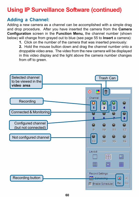
Using IP Surveillance Software (continued)Adding a Channel:Adding a new camera as a channel can be accomplished with a simple dragand drop procedure. After you have inserted the camera from the CameraConfiguration screen in the Function Menu, the channel number (shownbelow) will change from grayed out to blue (see page 55 to Insert a camera):
1. Click on the number of the camera that was inserted previously:2. Hold the mouse button down and drag the channel number onto adroppable video area. The video from the new camera will be displayedin this video display and the light above the camera number changesfrom off to green.
Trash Can
Recording button
Selected channelto be viewed in thevideo area
Connected & Monitoring
Recording
Configured channel(but not connected)
Not configured channel
61
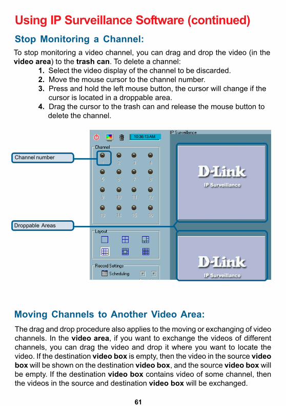
The drag and drop procedure also applies to the moving or exchanging of videochannels. In the video area, if you want to exchange the videos of differentchannels, you can drag the video and drop it where you want to locate thevideo. If the destination video box is empty, then the video in the source videobox will be shown on the destination video box, and the source video box willbe empty. If the destination video box contains video of some channel, thenthe videos in the source and destination video box will be exchanged.
Using IP Surveillance Software (continued)
To stop monitoring a video channel, you can drag and drop the video (in thevideo area) to the trash can. To delete a channel:
1. Select the video display of the channel to be discarded.2. Move the mouse cursor to the channel number.3. Press and hold the left mouse button, the cursor will change if the cursor is located in a droppable area.4. Drag the cursor to the trash can and release the mouse button to delete the channel.
Stop Monitoring a Channel:
Moving Channels to Another Video Area:
Droppable Areas
Channel number
10:36:13 AM

62
9 Cameras Layout
The LayoutThere are six layouts in the monitor tool. You can select (by left-clicking on theicon) which videos you want to monitor. In each layout, you can drag and dropthe �channel number� to any video box in the video area. If all conditions areokay, then the video will appear in the video box, and the old video is replaced.
The video positions in each layout are saved for the next time the layout isselected for monitoring.
When you want to view one individual camera, you can double-click on thevideo in the video area. The layout has now changed to the larger, single imagedisplay. You can click the up or down button to view different cameras, andclicking the Back button will switch to the previous selected layout.
6 Camera Layout
16 Camera Layout
Back toPrevious Layout
Switch BetweenCameras
Double-click toswitch to largersize Video
Using IP Surveillance Software (continued)
1Camera Layout

63
Record & Schedule
Record � Record the selected channel manually.Stop � Stop recording the selected channel manually.Scheduling � Arrange recording scheduleEnable Scheduler � Record according to the schedulersettings.
DI/DO ControlOnly one user with the administrator privilege can access the DI/DO control atthe same time. Refer to the following figure to control.
Using IP Surveillance Software (continued)
Digital Input is High
Set Digital Output to Low
Set Digital Output to High
Alert Message

64
If you turn on the Alert function, and a trigger is set off by motion, an alertmessage will show in this window. The message format is described as follows:
�time�=>�alert type� #�channel number�(�win1�,�win2",�win3")For example, the message �03:47:25 PM=>MO #5(0,1,1)� means that a motiondetection alert occurred at 03:47:25 PM in motion window 2 and in motionwindow 3.
Backup
The Backup function archives recorded data based on the location and sizeyou previously selected in Global Settings. You can duplicate the backup datato a removable device such as CD-ROM, ZIP disk, DVD-RAM or tape manually.After the backup starts, you cannot configure the camera or change any settings.You can cancel the backup process by selecting the Cancel Backup option.After the backup completes, a message appears informing you the backup iscomplete.
Using IP Surveillance Software (continued)

65
Miscellaneous Functions
Quit � Closes the application and saves last settings.
Full Screen � Switch to full screen video, double click the screen to return tothe previous view.
Local Time � Displays the current time.
Snapshot � Takes a snapshot from the selected video and saves it as a bitmapfile. You can set the directory in Global Settings.
Stop Alert Sound � Whenever an alert occurs, the alert sound will start toplay. You can press this button to stop the alert sound and see the alertmessages.
Using IP Surveillance Software (continued)
SchedulingThe recording scheduler helps you to schedule the recording time of the videofrom the DCS-2100+. You can easily specify the time of recording via both thegraphic user interface and time period selection. Features include:
Easy to use graphical user interface
One-on-one camera scheduling
Up to 9 schedule schemes for each camera
Automatic period recording
!!!!!
!!!!!
!!!!!
!!!!!
To enable scheduling, click the EnableScheduler box in the RecordSettings from the main screen of theMonitor program.

66
Using IP Surveillance Software (continued)The layout of the scheduler tool is divided into 9 sections. For ease of use,you may skip to section 7. In section 7, when you input the date, hour andminute, the times you have selected will appear in the Hour, Day, Week andMonth time-lines (sections 1,2,3 and 4 illustrated here.)
Section 3 is theWeek time-line.
Section 4 is theMonth time-line.
Section 5 is the Currentyear selector. Choosethe year here that will bedisplayed in Section 7.
Section 6 is thecamera selection andediting area it providesthe IP addresses andlocation information foryour reference. There isan editing schedulespace for saving atemporary schedule.This will be explained infurther detail on thefollowing pages.
Section 8 is theTime Periodselector. Select theperiod of time atwhich the settingswill apply. The Addand Erase buttonsare also in thissection. A detailedexplanation of thesefeatures can befound in thefollowing pages.
Section 1 of the scheduler tool is the Hour time-line. When you input the hour insection 7 it will be illustrated in section 1. Alternately, you can enter the schedulinghour in this timeline although it may be a less efficient method of inputting theinformation. You can refer to the Schedule With Time Lines section in the followingpages.
Section 2 is the Daytime-line. When youschedule the day insection 7, the result isdisplayed here.
Section 7 consists of Begintime selector, End timeselector, Period selector,Addition button, and Erasebutton. These componentshelp you choose a period oftime in which to add or deleterecords in the schedule.
Section 9 contains theoperation buttons. Thesewill be explained in thefollowing pages.
1
2
3
4
5
6 7
89

67
Current Year Settings And Camera Selector for the Recording function
The Date-time selector in Section 7 (see above) will change the yearconcurrently. If you change the year with the Date-time selector, the currentyear setting will also be changed.
The following is the Camera selector:
Here you can make two kinds of schedules: a schedule associated with a specificcamera, or a general schedule that is not applied to a specific camera.
If you want to make a schedule that does not belong to any camera, select thefirst row for editing.
If you want to create a schedule for a specificcamera, then click on the row of the camera youwish to schedule. Select the Begin and End Times.Add any other settings you wish to make. Click theAdd icon to save the changes.
Using IP Surveillance Software (continued)
By default, the scheduler is running with thecurrent date selected on the time-lines andDate-time picker. Therefore, the currentscheduling year is the year that you run thescheduler tool. To change the year setting:
Use the up (increase) anddown (decrease) arrows toadjust the year setting.
Camera
Add selectedperiodschedule
Erase selectedperiod schedule
2003

68
If users have configured the IP Surveillance software and the DCS-2100+camera, the IP address and location will show the correct setting. Please notethat when users switch between cameras, the changing of the schedule will besaved automatically.
The Schedule-Record-File operations
There are six related buttons. These buttons are illustrated on a prior page, assection 9 in the Scheduling window:
Load: This operation allows the users to load other schedulesfrom the schedule database for this camera.
Clear: This operation will clear all the schedule markers in thecurrent editing area.
Save: This button is for applying the changes for the currentschedule.
Save As: To save the current schedule-record-file to another filename.
Undo: Undo the most recent changes.
Using IP Surveillance Software (continued)
Close: Click Close to close this window.

69
Schedule with Time Picker
Remember to make the Begin Time earlier than the End Time. Otherwise theAdd action will be ignored.
Select period
OnceEvery HourEvery DayEvery Week
Using IP Surveillance Software (continued)
After you have made your Begin Time and End Time selections, select aperiod. You may want to record only Once, or you may want to record Everyhour, Every day, Every week or Every Month.
When you choose Every Hour, the recording scheduler will be guided only bythe minutes setting. Every hour recording will occur during the minutes thathave been selected. (e.g., if the Begin Time was 2:20pm and the End Timewas 7:40pm then the recording would be in effect from 20 minutes past thehour to 40 minutes past the hour for every hour of the day.)
Similarly, if you choose Every day then only the hour and the minute setting willapply. If you choose Every week then only the day of the week, the hour andthe minute settings are valid. For Every Month, only the date (excluding themonth and year), the hour and the minute are valid settings.
Addselectedperiodschedule
Eraseselectedperiodschedule

70
Playback Program
The Playback program is a powerful tool to assist you in browsing the recordedvideo database. It has two display modes (Normal display mode, Preview Mode)and three playback methods (Full Range, Time Period, Events Preview). Themain tools it provides include:
Powerful play control tool:
� Play
� Stop
� Pause
� Fast play (from x1 to x16)
� Slow play (from /1 to /16)
Convenient display adjustment tool:
� Zoom in
� Zoom out
� Full screen
Flexible searching range adjustment tool:
� User input (from full range to 1 second)
� Zoom in (from full range to 10 seconds)
� Zoom out (up to full range)
� Page searching
� Full range
Various exporting tools:
� AVI file transducer
� BMP file snapshot
� Output to printer directly
Using IP Surveillance Software (continued)

71
The main window will be shown on the top of the screen and the display resolutionwill change to 1024x768 automatically. There are four main areas in the window:Display area, Histogram area, Control area, and Status area. There arealso three controls the Area selection indicator, the Frame selectionindicator, and the Pull bar. Explanations of the main Playback screen follow:
Logging-inBefore you start the Playback software program, it is necessary to login. Forsecurity reasons, only the administrator account can login to Playback. Tochange the password of the admin account refer to the section of this manualtitled Logging-In located in the main section Using IP Surveillance software.After completing the installation of IP Surveillance, you can run the Playbackprogram from:Start\Program Files\D-Link\IP Surveillance\Playbackor the directory you specified during the installation.
Playback Program (continued)Using IP Surveillance Software (continued)
Installation of the IP Surveillance software is detailed in an earliersection of this manual titled Installation of IP Surveillance Softwareunder the main section titled Software Installation.
Display Area Control Area
Pull Bar Area
Area Selection Indicator
Status AreaHistogram Area

72
Display AreaThe display area shows the surveillance database of each camera by eventstriggered by an alert or by time. You can change the video size through theDisplay Adjustment Tool, and the playback method through the Play ControlTool. Under the normal display mode you can double click on the frame area tochange the frame size to a 1:1 or 2.25:1 ratio. In the Preview mode, doubleclicking on any frame area can change the display mode to normal and show a10-second interval including the event you selected.
Histogram AreaThe histogram is an interactive control. Not only can you get the event�s locationin terms of time, but you can select a group of events or period from the eventhistogram area and show it on the display area.
Control AreaThe control area contains almost all the control selectors and toolboxes youneed to browse the database (except the page control). The Page ControlTool is located on the right-bottom corner of the display area when the programis operating in the preview mode. These control tools include location selector,period selector, playback method selector, jog dial, display adjustment tool,exporting tool, and system control tool.
Status AreaThe Status Area is located at the bottom of the main window. It tells you aboutthe program status including display mode, display size, display speed, exportingfile format, and exporting file name.
Area Selection IndicatorIn the main Playback screen as shown above the display area has beenhighlighted with a yellow rectangle. This rectangle is the area selection indicator.This indicator can be set to either Display Area or Histogram Area, by movingyour mouse cursor to the Area you want to select. When you select the DisplayArea, the Display Adjustment Tool will appear in the control area, and if youselect the Histogram Area, the Display Adjustment Tool will disappear andthe Searching Range Adjustment Tool will be shown in the control area.
Playback Program (continued)
Using IP Surveillance Software (continued)

73
Explanations of the Settings screen are on the following pages.
Playback Program (continued)Using IP Surveillance Software (continued)
Frame Selection IndicatorThe frame selection indicator only appears when you change the display modeto Preview Mode. It appears as a red rectangle surrounding one of the nineEvent Preview Frames. Once you select one of these frames, you can controlits play status through the jog dial in the control area.
Pull BarThe Pull Bar is a fast, flexible control for seeking data in the selected timeperiod. It represents the total length of time in that period. You can click or pullthe indicator on the pull bar to the point you want to see. And the current displayingvideo will halt and start to play the video sequence from the point you choose.If the video sequence has been paused, the display area will show the pointyou select without playing. The Pull Bar will only function under the normaldisplay mode.
SettingsAfter the main window is shown on the screen, you must modify the settingsto make it work properly. Click on the Settings button in the system controltool, and the dialog box appears on the screen as shown below:

74
Database pathThe most important item in the settings dialog is the database path setting.You must set it to the directory that contains the surveillance database tomake the program work properly.
AVI file locationIt sets the storing directory when you export AVI files. The exported AVIfiles will be stored in the sub-directory under the directory you set herewith the name of the location you select.
Bitmap file locationIt sets the directory to use the for snapshots when exported as bitmapfiles. These exported bitmap files will be stored in the sub-directory underthe directory you set here with the name of the location you select.
AVI Frame rateThis setting sets the amount of frames per second that will be used toconvert a saved video into an AVI file.
Change AVI compression modeDuring the AVI compression mode selection, you can select one of thecompression methods that your computer supports to export the AVI file.
Alert window settingsThere are three alert windows you can activate during using the monitorprogram. In the playback program, you can choose whether these alertwindows will be shown or not. If you check one window, then you will seethat rectangle in green or red color shown in the displaying video sequence.
Modulation modeThe modulation mode should not be changed without knowledge of thevarious modes . The quality of the video depends on how you recorded thevideo sequence in the monitor program. If you select the wrong mode, thevideo shown in the display area will become deformed. If you choose thewrong modulation mode, you may open the settings dialog again, changeto the correct mode, and restart the playback program, It should then displayproperly.
Playback Program (continued)Using IP Surveillance Software (continued)

75
Control panel positionWith this setting you can place the Control panel on either the left or the right ofthe screen.
Once you change the setting of modulation or Control panel position, you haveto restart the program to for these changes to take effect. If you set the databasepath correctly, the video sequence will start displaying in the normal displaymode when you click on the OK button.
Normal (Single Frame) ModeYou can enter the Normal Mode when you:
� Change the database path in the settings dialog� Change the location selector to another location� Change the playback method selector to Full Range� Change the playback method selector to Time Period� Double click on one of the nine frames in the display area under
the preview mode.Under the single frame mode, you can use all the tools the playback programprovided except the Page Control. In this mode, the two labels under the pullbar show the start and end time of the period individually as shown below:
Histogram AreaThe Histogram Area in the single frame mode only shows the event�s occurredtime and the percentage of motion detection with red bars. If you want to accessthe Histogram Area, you must change the Area Selection Indicator to theHistogram Area. You can select a color-inverted region by dragging your mousewith the left button pressed. When you release the left button, the color-invertedregion will be enlarged to the whole histogram area.
Playback Program (continued)Using IP Surveillance Software (continued)
Period Start Time Label Period End Time Label
2003/01/15 00:28:442003/02/15 03:08:01

76
This color-inverted region will be the new time period the program is going todisplay. If you change your mind and don�t want to see that period, you cancancel it by just pressing the right button of your mouse with the left button stillpressed. If you click on the left button without dragging it, the action will be thesame as clicking on the Pull Bar in the same x-axis position. The dark regionsmean there is no video data in that interval. If you click on those regions, nothingwill happen except a warning message.
Preview (Multiple Frame) ModeYou can enter the preview mode only when you change the playback methodselector to Events Preview. Preview Mode helps you to identify the objectstriggering the events via not only the time information and the alert percentage,but also the video preview playing. This allows you to easily examine differentalert situations. Under the Preview Mode, the Pull Bar, Transducer buttonin Exporting Toolbox, and the Display Adjustment Toolbox are all disabled.The two labels under the pull bar show the displayed event number and thetotal event count individually. There are nine frames in the display area andthese are referred to as �one page�. Each frame displays a 10-second intervalvideo sequence that contains different events. You can use the Page Up andPage Down button in the page control to browse the events in the selectedperiod with nine events per page. And the page status tells you the currentpage number and total page count as shown below:
Dark Region
Inverted region
Displayed Event Number Total Event Count
Page Status
Page Up
Page Down
Playback Program (continued)Using IP Surveillance Software (continued)

77
Histogram AreaThe Histogram Area in the Preview Mode displays events that occurredpreviously as red bars, which represent the time and value of the event. Currentlydisplayed events are represented by green bars and the selected event withblue bars. If you want to access the histogram area, you must change the AreaSelection Indicator to the Histogram Area. You can select a color-invertedregion by dragging your mouse with the left button pressed.
When you release the left button, the color-inverted region will be enlarged tothe whole Histogram Area. This color-inverted region will be the new periodthe program is going to display. If you change your mind and don�t want to seethat period, you can cancel it by just pressing the right button of your mousewith the left button still pressed. If you click on the left button without draggingit, the display area will show the event page closest to the point you select. Thedark region means there is no video sequence in that interval. If you click onthese dark regions a warning dialog will appear to inform there is no videosequence available.
Location SelectorThe location selector is a control that lets you select the camera you want tosee. The location information is the same as the location specified in the monitorprogram (see Global Settings in the Monitor program section). If there ismore than one database in the same location, another dialog will appear (seebelow). You must select an interval in that dialog. The Playback program willautomatically switch to that camera and start displaying.
Playback Program (continued)Using IP Surveillance Software (continued)
Location selector
Period selector
Playback method selector
Alert area selector
Selector tools

78
Period SelectorPeriod selector provides a precise way to choose the start time and the endtime of a new period. The end time must be later than the start time. After yougive the correct start and end time, clicking on the Play button in the jog dial willplay the new period in the Display Area. If you change the period start and endtime label, the Pull Bar and Histogram Area will change, too. If the selectedperiod is not present in the database, the data in the Period Selector willchange to the previous correct start and end time and a warning message willbe displayed.
Playback Method SelectorFull RangeIf you select this method, the database will be displayed from the beginningto the end of this location. Any change in the period selector will take noeffect unless you change this selector to Time Period.
Time PeriodIf you change the playback method to Time Period, you can modify thestart and end time in the period selector. When you click on the Play buttonin the jog dial, the period you select will be displayed.
Events PreviewThis method will change the display mode from the normal display modeto the Preview Mode.
Playback Program (continued)Using IP Surveillance Software (continued)

79
Since the program will record the previous start and end time in Time Periodand Events Preview mode. Any time you want to change the period selectorto see another period, you must change the Playback Method Selector to themode you want to use first. Otherwise, the Period Selector will revert back tothe previous data used in Playback Method Selector.
Alert Area SelectorIn the Preview Mode, the Playback program only can show the eventinformation of one alert window at a time. If you want to see the events of theother two alert area windows, you must change the alert area selector to otheralert window numbers. In the normal display mode, the alert window that thealert area selector indicates will be highlighted with red rectangle if you checkedthat window in the settings dialog. The alert area selector will be changed toalert window zero, when you change the location selector to another one.
Play Control
For the play control, a jog dial is used to provide the easiest way to control thedisplaying video sequence. Except the Play button, all other buttons can controlthe displaying frame in the normal display mode and the selected displayingframe in the Preview mode.
PlayThe Play button is an intelligent play interface. The function of this buttonwill vary depending on differing circumstances. In the normal display mode,clicking on the Play button can restart the displaying video sequence. Whenin the Preview Mode, if you don�t change the data of Period Selector,clicking on this button only restarts the selected displaying frame. If thedata of the period selector has been changed, clicking on the Play buttonwill restart all frames to display the first nine events in the new period.
Playback Program (continued)Using IP Surveillance Software (continued)
Speed Indicator
ForwardPlay
Stop
Pause

80
StopWhen you want to stop the displaying video sequence, you can click onthe Stop button. Once you have pressed the Stop button, the start pointwill be reset to the start of the present period.
PauseThe Pause button provides you a way to pause the displaying videosequence. When the displaying video is paused, clicking on the Pausebutton again will continue the video to display.
Step ForwardThis button is only valid when the displaying video sequence is paused. Itwill display the next frame in that period when you click on the StepForward button one time.
Fast Play and Slow PlayThe DCS-2100+ supports up to 16X fast forward play and slow forward play.If you want to change the playing speed, move the speed indicator. To increaseplaying speed, move the indicator in the clockwise direction. And to decreaseplaying speed, move it in the counterclockwise direction. The current speedyou set will be shown in the second column of status area.
Display Adjustment ToolboxUsing the Display Adjustment Toolbox, you can change the displaying videosequence to the size you want to see in the normal display mode when youmove the area selection indicator to the display area. Below is the DisplayAdjustment Toolbox and its own three elements, i.e. Zoom In, Zoom Out,and Full Screen.
Zoom In
When you click on the Zoom In button one time, the image size in the displayarea will be magnified 12.5 percent to the original size. The maximum zoom-in ratio 2.25:1 for NTSC modulation mode and 1.875:1 for PAL modulationmode. If you want to see the image in more detail, you can use the fullscreen function in the same toolbox.
Playback Program (continued)Using IP Surveillance Software (continued)

81
Zoom Out
When you click on the Zoom Out button one time, the image size in the displayarea will be reduced 12.5 percent to the original size. To show the location andtime information completely, the minimum zoom out ratio is limited in 0.5:1.
Full Screen
When you click on the Full Screen button, the video sequence will be enlargedto fill the whole screen. You can double click on any place to return to the originalstate. When you switch to full screen display, you can press the Alt and Spacekeys together to pop the jog dial to control the displaying video sequence. Pressthe same keys again will close the jog dial. You can also press the Alt andEnter keys together to switch between the normal display and full screen displayat any time when the program is under the normal display mode.
Searching Range Adjustment ToolboxThe Searching Range Adjustment Toolbox provides you a faster way tochange the range of the displayed time period. By using this toolbox, you canbrowse the database of one location from any 10-second interval over its entirerange. Below is the Searching Range Adjustment Toolbox with its own threeelements: Zoom In, Zoom Out, and Full Range.
Zoom In
Each time you click on the Zoom In button in the searching range adjustmenttoolbox, the displayed time period will be half in the center of the original timeperiod until the period is equal to 10 seconds. You can see the new interval inmore details. The scale of pull bar and alert histogram window changes andthe period start and end time change, too. The period selector will show thenew start and end time. And the display area will restart to display the newperiod from the new start time.
Playback Program (continued)Using IP Surveillance Software (continued)

82
Zoom Out
Each time you click on the Zoom Out button in the searching range adjustmenttoolbox, the displayed time period will be double in the center of the originaltime period unless the start time or end time exceed the database boundary.The scale of pull bar and alert histogram window changes and the period startand end time change, too. The period selector will show the new start and endtime. And the display area will restart to display the new period from the newstart time.
Full Range
As you click on the Full Range button, you will get the same functionality as ifyou changed the Playback Method Selector to Full Range.
Transducer
Using the Transducer tool, you can convert the displayed video sequence toan AVI format file. Just click on the Transducer button and a dialog box appears(shown below) asking to confirm transforming a database into an AVI file. Whenyou click on the OK button, the conversion procedure will be started.
Playback Program (continued)Using IP Surveillance Software (continued)
Exporting ToolboxYou can check the database through the Playback program and also exportthe database to other media. Using the Exporting Toolbox, you can export thedatabase to other more portable formats, such as AVI file, bitmap file or paper.Then you may use Programs such as Microsoft Windows Media Player orother programs to browse the exporting data. Under the normal display mode,you can use all the exporting tools. And under the Preview Mode, only snapshotand print can be used. Shown below are three elements of the ExportingToolbox: Transducer, Snapshot and Print.
®

83
The time required to Export data depends on the speed of the computer andprocessor that you are using. At any time during the export, you can click onthe Stop button in the jog dial to stop the procedure. Then you will get an AVI filefrom the start time to the time you clicked the Stop button. The exported AVIfilename will be generated automatically and will be listed in the fourth columnof the status area. If you want to change the output directory, you can go to theSettings Window (See Page 73). To increase the quality of an exported AVIfile, it is suggested to set the video format to normal size (please refer to theCamera Configurations section on Page 54 and Page 35 for setting the videoformat).
Snapshot
When you click on the Snapshot button one time, the program will export abitmap. In the normal display mode, the exporting bitmap is the image shown inthe display area. And in the Preview Mode, it is the image that you selectedthrough the Frame Selection Indicator. The size of the bitmap will be thesame as that of the image you select. The exported bitmap filename will begenerated automatically and listed in the fourth column of the status area. Ifyou want to change the output directory, you can go to the Settings window.
When you click on the Print button, a dialog box appears. After you make yourselection and send to the printer, the images on the Display Area will be printedout.
Playback Program (continued)Using IP Surveillance Software (continued)
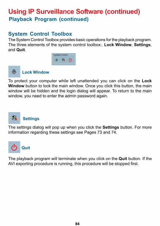
84
Lock Window
To protect your computer while left unattended you can click on the LockWindow button to lock the main window. Once you click this button, the mainwindow will be hidden and the login dialog will appear. To return to the mainwindow, you need to enter the admin password again.
Settings
The settings dialog will pop up when you click the Settings button. For moreinformation regarding these settings see Pages 73 and 74.
Quit
The playback program will terminate when you click on the Quit button. If theAVI exporting procedure is running, this procedure will be stopped first.
System Control ToolboxThe System Control Toolbox provides basic operations for the playback program.The three elements of the system control toolbox:. Lock Window, Settings,and Quit.
Playback Program (continued)Using IP Surveillance Software (continued)

85
The DCS-2100+ Internet Camera supports firmware upgrades (the softwarethat controls the operation in the DCS-2100+). D-Link will supply the latestfirmware version on the D-Link support Web site at: support.dlink.com.
To upgrade the firmware:Download the latest firmware file from D-Link.Click on the file Upgrade Wizard located on the CD enclosed with theDCS-2100+.Power on the DCS-2100+ and connect it to the Ethernet port of your computer.The Wizard will ask for the IP Address of your camera and for your administratorpassword:
Firmware Upgrades
Click Next
The Upgrade Wizard will attempt to find the DCS-2100+. If it cannot, an errormessage indicating this will appear.

86
If the Upgrade Wizard finds the Internet Camera the following screen asks forthe file name or gives you the choice to browse for the file. The file nameshould be FLASH.BIN for the DCS-2100+ Internet Camera.
Firmware Upgrades (continued)
The firmware file is scanned by the Upgrade Wizard and the version is reportedto you.
Click Yes
After clicking Yes the upgrade begins. The progress of the upgrade is displayedon the this screen:
Click Next

87
Firmware Upgrades (continued)
The download firmware procedure cannot be interrupted.If the power or network connections are broken duringthe download procedure it might possibly cause seriousdamage to the Internet Camera.
Warning
Click Exit

88
AppendixFrequently Asked QuestionsInternet Camera FeaturesQ: What is an Internet Camera?A: The Internet Camera is a standalone system connecting directly to anEthernet or Fast Ethernet network. It differs from a conventional PC Camera,the Internet Camera is an all-in-one system with built-in CPU and Web-basedsolutions providing a low cost solution that can transmit high quality video imagesfor monitoring. The Internet Camera can be managed remotely, accessed andcontrolled from any PC/Notebook over an Intranet or the Internet from a Webbrowser.
Q: What is the maximum number of users that can be allowed to accessDCS-2100+ simultaneously?A: The maximum number of users that can log onto the Internet Camera at thesame time is 10. Please keep in mind the overall performance of the transmissionspeed will slow down when many users are logged on.
Q: What algorithm is used to compress the digital image?A: The Internet Camera utilizes H.263+ MPEG-4 Short Header Mode imagecompression technology providing high quality images. MPEG is a standard forimage compression and can be applied to various Web browser and applicationsoftware without the need to install extra software.
Q: Can I capture still images from the Internet Camera?A: Yes you are able to capture still images with the snapshot function from thesoftware application CD supplied with the Internet Camera.
Internet Camera InstallationQ: Can the Internet Camera be used outdoors?A: The Internet Camera is not weatherproof. It needs to be equipped with aweatherproof case to be used outdoors and it is not recommended.
Q: When physically connecting the Internet Camera to a network whatnetwork cabling is required?A: The Internet Camera uses Category 5 UTP cable allowing 10 Base-T and100 Base-T networking.

89
Q: Can the Internet Camera be setup as a PC-cam on a computer?A: No, the DCS-2100+ Internet Camera is used only on an wireless 802.11b,Ethernet or Fast Ethernet network. The D-Link DSB-C110, DSB-C310 can beused as a PC Camera (Webcam).
Q: Can the DCS-2100+ be connected on the network if it consists of onlyprivate IP addresses?A: The Internet Camera can be connected to a LAN with private IP addresses.
Q: Can the DCS-2100+ be installed and work if a firewall exists on thenetwork?A: If a firewall exists on the network, port 80 is open for ordinary datacommunication. The DCS-2100+ uses port 5001 for control and synchronization,port 5002 for streaming audio and port 5003 for streaming video. These ports(or the ports you specify from the Advanced Tab in the Configuration screen ifyou change the default ports) need to be opened on the firewall.
Q: Why am I unable to access the DCS-2100+ from a Web browser?A1: If a router or firewall is used on the network, the correct ports for theDCS-2100+ may not be configured on the router or firewall. To correct theproblem, you need to determine if the DCS-2100+ is behind a router or firewalland if the router or firewall is properly configured for the ports the DCS-2100+is using. Refer to Page 19 for help in opening the correct ports on a router orfirewall for use with the DCS-2100+.A2: Other possible problems might be due to the network cable. Try replacingyour network cable. Test the network interface of the product by connecting alocal computer to the unit, utilizing a Ethernet crossover cable. If the problem isnot solved the Internet Camera might be faulty.
Q: Why does the Internet Camera work locally but not externally?A1: This might be caused by network firewall protection. The firewall may needto have some settings changed in order for the Internet Camera to be accessibleoutside your local LAN. Check with the Network Administrator for your network.A2: Make sure that the Internet Camera isn�t conflicting with any Web serveryou may have running on your network.A3: The default router setting might be a possible reason. Check that theconfiguration of the router settings allow the Internet Camera to be accessedoutside your local LAN.
Frequently Asked Questions (continued)

90
Q: Why does a series of broad vertical white lines appear throughoutthe image?A: It could be that the CMOS sensor has become overloaded when it has beenexposed to bright lights such as direct exposure to sunlight or halogen lights.Reposition the Internet Camera into a more shaded area immediately asprolonged exposure to bright lights will damage the CMOS sensor.
Q: The focus on the Internet Camera is bad, how can I correct it?A1: Adjust the Internet Camera focus manually as described in Adjusting theInternet Camera Focus in the Appendix section of this manual.A2: If you have previously changed the supplied CS-type lens, you may haveunintentionally installed a C-type lens without fitting the adaptor first.
Q: Noisy images occur. How can I solve the problem?A1: The video images might be noisy if the Internet Camera is used in a verylow light environment. To solve this issue you need more lighting.
Frequently Asked Questions (continued)Q: I connected the Internet Camera directly to a computer with a cross-over cable Ethernet cable and received the following Windows error uponrunning IP Installer:
A1: This Windows error will occur if the Internet Camera is connected to acomputer that is not properly configured with a valid IP address. Turn off DHCPfrom the Network Settings in Windows and configure the computer with a validIP address or connect the camera to a router with DHCP enabled.A2:This error can also occur if the IP Installer icon is clicked on more thanonce from the setup wizard.

91
Q: The images appear to be of poor quality, how can I improve the imagequality?
A1: Make sure that your computer�s display properties are set above 256 colors.Using 16 or 256 colors on your computer will produce dithering artifacts in theimage, making the image appear to be of poor quality.
A2: The configuration on the Internet Camera image display is incorrect. Throughthe Advanced>Configuration section of the Web management you need toadjust the image related parameters such as brightness, contrast, hue andpower line frequency for fluorescent light . Please refer to theAdvanced>Configuration>Video section on Page 35 and 36 for detailedinformation.
How to PING Your IP AddressThe PING (Packet Internet Groper) command can determine whether a specificIP address is accessible by sending a packet to the specific address and waitingfor a reply. It can also provide a very useful tool to confirm if the IP addressconflicts with Internet Camera over the network.
Follow the step-by-step procedure below to utilize the PING command but firstyou must disconnect Internet Camera from the network.
Start a DOS window.Type ping x.x.x.x, where x.x.x.x is the IP address of the Internet Camera.
The replies, as illustrated below, will help diagnose any connection problems.
Frequently Asked Questions (continued)

92
There is a button hidden in the pinhole beside the Ethernet socket. It isused to reset the system or restore the factory default settings.Sometimes resetting the DCS-2100+ will return the system back to anormal state. If the system still has problems after reset, restore thefactory settings and install again:
RESET: 1. Lightly insert a paper clip (or a similar sized tool) into the reset hole on the back of the camera, press lightly and then release the button.2. The LED on the front of the camera will begin blinking red and green.3. When the LED stops the blinking the reset has completed.
RESTORE: 1. Insert the paper clip or other tool and press on the button continuously.2. Wait for the LED on the front of the camera to blink red and green and hold the button through two cycles of blinking (about 5-7 seconds.)3. Withdraw the tool after the second cycle of the LED blinking and a factory restore has been completed.
Reset and Restore
Reset button
Restoring the factory defaults will result in theloss of any previous settings and will requirerunning the IP Installer to return theDCS-2100+ to a normal state.

93
I/O ConnectorI/O Connector Definition for the Internet CameraThe DCS-2100+ provides a general I/O terminal block with one digital input andone relay switch for device control. Pin 1 and pin 2 can be connected to anexternal sensor and the state of voltage will be monitored from the initial state�LOW�. The relay switch of pin 3 and pin 4 can be used to turn on or off theexternal device.
The I/O connector provides the physical interface for digital output (DO) anddigital input (DI) that is used for connecting a diversity of external alarm devicesto the Internet Camera such as IR-Sensors and alarm relays.
The digital input is used for connecting external alarm devices and once triggeredimages will be taken and e-mailed.
1 DI+ INPUT (Max. 50mA, 12VDC)2 DI- INPUT (Initial state of DI is low)3 SW_COMMON OUTPUT (open from SW_OPEN at initial state)
(close with SW_OPEN when set DO to ON)4 SW_NOPEN OUTPUT (Max. 1A, 24VDC or 0.5A, 125VAC)
I/O Terminal Block:
I/O Connector

94
Note:You can further adjust the Internet Camera�s image quality throughthe web configuration under:Configuration > Advanced > VideoPlease refer to Using the DCS-2100+ section for further details.
Adjusting the Camera FocusThe DCS-2100+ Internet Camera features an interchangeable C/CS-type lensthat can be used for different applications as necessary. It supports rotationalfocus control so the lens can be adjusted to focus under normal and stableconditions to maximize the image quality of the Internet Camera.
To adjust the focus of the lens you will need to turn the lens slowly eitherclockwise or counterclockwise until the desired image appears. DO NOToverturn the lens in either direction as it will be out of focus. Unless you want tosubstitute the lens DO NOT unscrew more than 1.0mm apart from the FixedLens Assembly.
To help you get the best image quality, keep in mind that while adjusting thecameras focus you can preview the image quality from your Web browser.
Camera LensAdjust focus by turning
clockwise or counterclockwise
Fixed Lens AssemblyDo NOT adjust

95
Replacing the LensSince the DCS-2100+ Internet Camera is designed with a CS-mount, the lensequipped with the Internet Camera can be replaced with any standard C or CS-mount lens commonly used within the surveillance industry.
Follow the instructions below to replace the supplied lens with any C or CS-mount lens.
1. Unscrew the Internet Camera lens2. When using a C-mount lens, attach the new lens to a CS to C-mount
adapter.3. Screw the new lens onto the Internet Camera.4. Refer to Adjusting the Internet Camera Focus on the previous page.5. Refresh the Web browser and monitor the results from the Internet Camera.
Warning!Direct exposure to sunlight may cause permanentdamage to the CMOS sensor. Therefore do not ex-pose the Internet Camera�s lens directly to sunlight.When operation is required in glaring light environment,it is recommended to use an iris lens.
The Internet Camera is designed for indoor usage and if your appli-cation requires prolonged exposure to sunlight, a sun visor is rec-ommended to protect the Internet Camera.

96
Remote managementCamera configuration and Camera system log can be accessed remotely via InternetExplorer 5.x or above Web browser.
NetworkingProtocolTCP/IP, HTTP, SMTP, FTP, NTP, DNS and DHCPEthernetEnhanced 802.11b wireless or 10BaseT or 100BaseT Fast Ethernet auto-negotiationWLAN2.4Hhz 802.11b+ DSSS CSMA/CA ProtocolBit rate: 22/11/5.5/2/1 MbpsSecurity: Up to 256-bit WEP
Antenna2.4Ghz swivel type, monopoleFrequency2.4Ghz-2.5GhzImpedance50 Ohms nominalGain2dBi typical
VideoAlgorithm supportedH.263+ (MPEG-4 Short header mode)FeaturesThree adjustable image sizes and motion detection windows with adjustable bit rate
Audio24Kbps8K sampling rate
Video resolutionUp to 30 fps at 160x120Up to 30 fps at 320x240
General I/O1 opto-isolated sensor input (max. 12VDC 50mA)1 relay output (max. 24VDC 1A, 125VAC 0.5A)
SecurityAdministrator and user group protectedPassword authentication
Technical Specifications

97
LED indicatorBi-color status indicator
Camera specification1/3 inch color CMOS sensor2.5Lux/F1.4AGC/AWBElectronic shutter: 1/60 ~ 1/15000 secondStandard CS mount type lens, 6mm, F1.8
Power12VDC 1.5A, external power supply
Weight328 grams
Dimension160mm(L) x 83.5mm(W) x 54mm(H)
Viewing system requirementProtocolStandard TCP/IP Internet SuiteActiveXOperating systemMicrosoft Windows XP, 2000, ME or 98SEBrowserInternet Explorer 5.x or above
EnvironmentalOperating40° to 113° FStorage-4° to 158° FHumidityMax 95% RH
SafetyFCC class BCE
Technical Specifications (continued)

98
Contacting Technical Support
Technical SupportTechnical SupportTechnical SupportTechnical SupportTechnical SupportYou can find software updates and user documentation on the D-Link website.
D-Link provides free technical support for customers within the United States andwithin Canada for the duration of the warranty period on this product.
U.S. and Canadian customers can contact D-Link Technical Support through ourwebsite, or by phone.
Tech Support for customers within the United States:D-Link Technical Support over the Telephone:(877) 453-546524 hours a day, seven days a week.
D-Link Technical Support over the Internet:http://support.dlink.comemail:[email protected]
Tech Support for customers within Canada:D-Link Technical Support over the Telephone:(800) 361-5265Monday to Friday 8:30am to 9:00pm EST
D-Link Technical Support over the Internet:http://support.dlink.caemail:[email protected]

99
Time Zone TableGMT stands for Greenwich Mean Time, which is the global time that alltime zones are measured from.

100
Time Zone Table (continued)

101
Subject to the terms and conditions set forth herein, D-Link Systems, Inc. (�D-Link�) provides this Limitedwarranty for its product only to the person or entity that originally purchased the product from:• D-Link or its authorized reseller or distributor and• Products purchased and delivered within the fifty states of the United States, the District of Columbia,
U.S. Possessions or Protectorates, U.S. Military Installations, addresses with an APO or FPO.Limited Warranty: D-Link warrants that the hardware portion of the D-Link products described below will befree from material defects in workmanship and materials from the date of original retail purchase of theproduct, for the period set forth below applicable to the product type (�Warranty Period�), except as otherwisestated herein.1-Year Limited Warranty for the Product(s) is defined as follows:• Hardware (excluding power supplies and fans) One (1) Year• Power Supplies and Fans One (1) Year• Spare parts and spare kits Ninety (90) daysD-Link�s sole obligation shall be to repair or replace the defective Hardware during the Warranty Period at nocharge to the original owner or to refund at D-Link�s sole discretion. Such repair or replacement will berendered by D-Link at an Authorized D-Link Service Office. The replacement Hardware need not be new orhave an identical make, model or part. D-Link may in its sole discretion replace the defective Hardware (orany part thereof) with any reconditioned product that D-Link reasonably determines is substantially equivalent(or superior) in all material respects to the defective Hardware. Repaired or replacement Hardware will bewarranted for the remainder of the original Warranty Period from the date of original retail purchase. If amaterial defect is incapable of correction, or if D-Link determines in its sole discretion that it is not practicalto repair or replace the defective Hardware, the price paid by the original purchaser for the defective Hardwarewill be refunded by D-Link upon return to D-Link of the defective Hardware. All Hardware (or part thereof) thatis replaced by D-Link, or for which the purchase price is refunded, shall become the property of D-Link uponreplacement or refund.Limited Software Warranty: D-Link warrants that the software portion of the product (�Software�) willsubstantially conform to D-Link�s then current functional specifications for the Software, as set forth in theapplicable documentation, from the date of original retail purchase of the Software for a period of ninety (90)days (�Warranty Period�), provided that the Software is properly installed on approved hardware and operatedas contemplated in its documentation. D-Link further warrants that, during the Warranty Period, the magneticmedia on which D-Link delivers the Software will be free of physical defects. D-Link�s sole obligation shall beto replace the non-conforming Software (or defective media) with software that substantially conforms to D-Link�s functional specifications for the Software or to refund at D-Link�s sole discretion. Except as otherwiseagreed by D-Link in writing, the replacement Software is provided only to the original licensee, and is subjectto the terms and conditions of the license granted by D-Link for the Software. Software will be warranted forthe remainder of the original Warranty Period from the date or original retail purchase. If a material non-conformance is incapable of correction, or if D-Link determines in its sole discretion that it is not practical toreplace the non-conforming Software, the price paid by the original licensee for the non-conforming Softwarewill be refunded by D-Link; provided that the non-conforming Software (and all copies thereof) is first returnedto D-Link. The license granted respecting any Software for which a refund is given automatically terminates.Non-Applicability of Warranty: The Limited Warranty provided hereunder for hardware and software of D-Link�s products will not be applied to and does not cover any refurbished product and any product purchasedthrough the inventory clearance or liquidation sale or other sales in which D-Link, the sellers, or the liquidatorsexpressly disclaim their warranty obligation pertaining to the product and in that case, the product is beingsold �As-Is� without any warranty whatsoever including, without limitation, the Limited Warranty as describedherein, notwithstanding anything stated herein to the contrary.
Submitting A Claim: The customer shall return the product to the original purchase point based on itsreturn policy. In case the return policy period has expired and the product is within warranty, the customershall submit a claim to D-Link as outlined below:
• The customer must submit with the product as part of the claim a written description of the Hardwaredefect or Software nonconformance in sufficient detail to allow D-Link to confirm the same.
Warranty and RegistrationUSA only
• The original product owner must obtain a Return Material Authorization (�RMA�) number from theAuthorized D-Link Service Office and, if requested, provide written proof of purchase of the product (suchas a copy of the dated purchase invoice for the product) before the warranty service is provided.

102
• After an RMA number is issued, the defective product must be packaged securely in the original orother suitable shipping package to ensure that it will not be damaged in transit, and the RMA numbermust be prominently marked on the outside of the package. Do not include any manuals or accessoriesin the shipping package. D-Link will only replace the defective portion of the Product and will not shipback any accessories.
• The customer is responsible for all in-bound shipping charges to D-Link. No Cash on Delivery(�COD�) is allowed. Products sent COD will either be rejected by D-Link or become the property of D-Link. Products shall be fully insured by the customer and shipped to D-Link Systems, Inc., 53 DiscoveryDrive, Irvine, CA 92618. D-Link will not be held responsible for any packages that are lost in transit toD-Link. The repaired or replaced packages will be shipped to the customer via UPS Ground or anycommon carrier selected by D-Link, with shipping charges prepaid. Expedited shipping is available ifshipping charges are prepaid by the customer and upon request.
D-Link may reject or return any product that is not packaged and shipped in strict compliance with theforegoing requirements, or for which an RMA number is not visible from the outside of the package. Theproduct owner agrees to pay D-Link�s reasonable handling and return shipping charges for any product thatis not packaged and shipped in accordance with the foregoing requirements, or that is determined by D-Linknot to be defective or non-conforming.What Is Not Covered: This limited warranty provided by D-Link does not cover: Products, if in D-Link�sjudgment, have been subjected to abuse, accident, alteration, modification, tampering, negligence, misuse,faulty installation, lack of reasonable care, repair or service in any way that is not contemplated in thedocumentation for the product, or if the model or serial number has been altered, tampered with, defaced orremoved; Initial installation, installation and removal of the product for repair, and shipping costs; Operationaladjustments covered in the operating manual for the product, and normal maintenance; Damage that occursin shipment, due to act of God, failures due to power surge, and cosmetic damage; Any hardware, software,firmware or other products or services provided by anyone other than D-Link; Products that have beenpurchased from inventory clearance or liquidation sales or other sales in which D-Link, the sellers, or theliquidators expressly disclaim their warranty obligation pertaining to the product. Repair by anyone otherthan D-Link or an Authorized D-Link Service Office will void this Warranty.Disclaimer of Other Warranties: EXCEPT FOR THE LIMITED WARRANTY SPECIFIED HEREIN, THEPRODUCT IS PROVIDED �AS-IS� WITHOUT ANY WARRANTY OF ANY KIND WHATSOEVER INCLUDING,WITHOUT LIMITATION, ANY WARRANTY OF MERCHANTABILITY, FITNESS FOR A PARTICULAR PURPOSEAND NON-INFRINGEMENT. IF ANY IMPLIED WARRANTY CANNOT BE DISCLAIMED IN ANY TERRITORYWHERE A PRODUCT IS SOLD, THE DURATION OF SUCH IMPLIED WARRANTY SHALL BE LIMITED TONINETY (90) DAYS. EXCEPT AS EXPRESSLY COVERED UNDER THE LIMITED WARRANTY PROVIDEDHEREIN, THE ENTIRE RISK AS TO THE QUALITY, SELECTION AND PERFORMANCE OF THE PRODUCTIS WITH THE PURCHASER OF THE PRODUCT.Limitation of Liability: TO THE MAXIMUM EXTENT PERMITTED BY LAW, D-LINK IS NOT LIABLE UNDERANY CONTRACT, NEGLIGENCE, STRICT LIABILITY OR OTHER LEGAL OR EQUITABLE THEORY FORANY LOSS OF USE OF THE PRODUCT, INCONVENIENCE OR DAMAGES OF ANY CHARACTER,WHETHER DIRECT, SPECIAL, INCIDENTAL OR CONSEQUENTIAL (INCLUDING, BUT NOT LIMITED TO,DAMAGES FOR LOSS OF GOODWILL, LOSS OF REVENUE OR PROFIT, WORK STOPPAGE, COMPUTERFAILURE OR MALFUNCTION, FAILURE OF OTHER EQUIPMENT OR COMPUTER PROGRAMS TO WHICHD-LINK�S PRODUCT IS CONNECTED WITH, LOSS OF INFORMATION OR DATA CONTAINED IN, STOREDON, OR INTEGRATED WITH ANY PRODUCT RETURNED TO D-LINK FOR WARRANTY SERVICE)RESULTING FROM THE USE OF THE PRODUCT, RELATING TO WARRANTY SERVICE, OR ARISINGOUT OF ANY BREACH OF THIS LIMITED WARRANTY, EVEN IF D-LINK HAS BEEN ADVISED OF THEPOSSIBILITY OF SUCH DAMAGES. THE SOLE REMEDY FOR A BREACH OF THE FOREGOING LIMITEDWARRANTY IS REPAIR, REPLACEMENT OR REFUND OF THE DEFECTIVE OR NON-CONFORMINGPRODUCT. THE MAXIMUM LIABILITY OF D-LINK UNDER THIS WARRANTY IS LIMITED TO THE PURCHASEPRICE OF THE PRODUCT COVERED BY THE WARRANTY. THE FOREGOING EXPRESS WRITTENWARRANTIES AND REMEDIES ARE EXCLUSIVE AND ARE IN LIEU OF ANY OTHER WARRANTIES ORREMEDIES, EXPRESS, IMPLIED OR STATUTORYGoverning Law: This Limited Warranty shall be governed by the laws of the State of California. Some statesdo not allow exclusion or limitation of incidental or consequential damages, or limitations on how long animplied warranty lasts, so the foregoing limitations and exclusions may not apply. This limited warrantyprovides specific legal rights and the product owner may also have other rights which vary from state to state.
Warranty and RegistrationUSA only (continued)

103
Trademarks: D-Link is a registered trademark of D-Link Systems, Inc. Other trademarks or registeredtrademarks are the property of their respective manufacturers or owners.
Copyright Statement: No part of this publication or documentation accompanyingthis Product may be reproduced in any form or by any means or used to make anyderivative such as translation, transformation, or adaptation without permission fromD-Link Corporation/D-Link Systems, Inc., as stipulated by the United StatesCopyright Act of 1976. Contents are subject to change without prior notice.Copyright© 2002 by D-Link Corporation/D-Link Systems, Inc. All rights reserved.
CE Mark Warning: This is a Class B product. In a domestic environment, this product may cause radiointerference, in which case the user may be required to take adequate measures.
FCC Statement: This equipment has been tested and found to comply with the limits for a Class B digitaldevice, pursuant to part 15 of the FCC Rules. These limits are designed to provide reasonable protectionagainst harmful interference in a residential installation. This equipment generates, uses, and can radiateradio frequency energy and, if not installed and used in accordance with the instructions, may cause harmfulinterference to radio communication. However, there is no guarantee that interference will not occur in aparticular installation. If this equipment does cause harmful interference to radio or television reception,which can be determined by turning the equipment off and on, the user is encouraged to try to correct theinterference by one or more of the following measures:• Reorient or relocate the receiving antenna.• Increase the separation between the equipment and receiver.• Connect the equipment into an outlet on a circuit different from that to which the receiver is connected.• Consult the dealer or an experienced radio/TV technician for help.
Warranty and RegistrationUSA only (continued)
For detailed warranty outside the United States, please contact corresponding localD-Link office.
Register online your D-Link product at http://support.dlink.com/register/