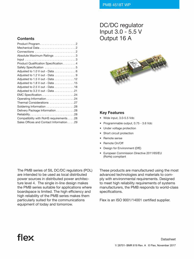
DC/DC regulator Input 3.0 - 5.5 V Output 16 A
28
Key Features • Wide input, 3.0-5.5 Vdc • Programmable output, 0.75 - 3.6 Vdc • Under voltage protection • Short circuit protection • Remote sense • Remote On/Off • Design for Environment (DfE) • European Commission Directive 2011/65/EU (RoHs) compliant Datasheet DC/DC regulator Input 3.0 - 5.5 V Output 16 A PMB 4518T WP The PMB series of SIL DC/DC regulators (POL) are intended to be used as local distributed power sources in distributed power architec- ture level 4. The single in-line design makes the PMB series suitable for applications where boardspace is limited. The high efficiency and high reliability of the PMB series makes them particularly suited for the communications equipment of today and tomorrow. These products are manufactured using the most advanced technologies and materials to com- ply with environmental requirements. Designed to meet high reliability requirements of systems manufacturers, the PMB responds to world-class specifications. Flex is an ISO 9001/14001 certified supplier. Contents Product Program ...................... 2 Mechanical Data ...................... 2 Connections ......................... 2 Absolute Maximum Ratings ............. 3 Input ............................... 3 Product Qualification Specification ........ 4 Safety Specification ................... 5 Adjusted to 1.0 V out - Data ............. 6 Adjusted to 1.2 V out - Data ............. 9 Adjusted to 1.5 V out - Data ............ 12 Adjusted to 1.8 V out - Data ............ 15 Adjusted to 2.5 V out - Data ............ 18 Adjusted to 3.3 V out - Data ............ 21 EMC Specification.................... 24 Operating Information ................. 24 Thermal Considerations ............... 27 Soldering Information ................. 28 Delivery Package Information ........... 28 Reliability ........................... 28 Compatibility with RoHS requirements .... 28 Sales Offices and Contact Information .... 29 1/ 28701- BMR 619 Rev. A © Flex, November 2017
Transcript of DC/DC regulator Input 3.0 - 5.5 V Output 16 A
Key Features • Wideinput,3.0-5.5Vdc
• Programmableoutput,0.75-3.6Vdc
• Undervoltageprotection
• Shortcircuitprotection
• Remotesense
• RemoteOn/Off
• DesignforEnvironment(DfE)
• EuropeanCommissionDirective2011/65/EU(RoHs)compliant
Datasheet
DC/DCregulatorInput3.0-5.5VOutput16A
PMB4518TWP
ThePMBseriesofSILDC/DCregulators(POL)areintendedtobeusedaslocaldistributedpowersourcesindistributedpowerarchitec-turelevel4.Thesinglein-linedesignmakesthePMBseriessuitableforapplicationswhereboardspaceislimited.ThehighefficiencyandhighreliabilityofthePMBseriesmakesthemparticularlysuitedforthecommunicationsequipmentoftodayandtomorrow.
Theseproductsaremanufacturedusingthemostadvancedtechnologiesandmaterialstocom-plywithenvironmentalrequirements.Designedtomeethighreliabilityrequirementsofsystemsmanufacturers,thePMBrespondstoworld-classspecifications.
FlexisanISO9001/14001certifiedsupplier.
ContentsProductProgram. . . . . . . . . . . . . . . . . . . . . . 2MechanicalData. . . . . . . . . . . . . . . . . . . . . . 2Connections . . . . . . . . . . . . . . . . . . . . . . . . . 2AbsoluteMaximumRatings . . . . . . . . . . . . . 3Input. . . . . . . . . . . . . . . . . . . . . . . . . . . . . . . 3ProductQualificationSpecification. . . . . . . . 4SafetySpecification . . . . . . . . . . . . . . . . . . . 5Adjustedto1.0Vout-Data. . . . . . . . . . . . . 6Adjustedto1.2Vout-Data. . . . . . . . . . . . . 9Adjustedto1.5Vout-Data. . . . . . . . . . . . 12Adjustedto1.8Vout-Data. . . . . . . . . . . . 15Adjustedto2.5Vout-Data. . . . . . . . . . . . 18Adjustedto3.3Vout-Data. . . . . . . . . . . . 21EMCSpecification. . . . . . . . . . . . . . . . . . . . 24OperatingInformation. . . . . . . . . . . . . . . . . 24ThermalConsiderations . . . . . . . . . . . . . . . 27SolderingInformation. . . . . . . . . . . . . . . . . 28DeliveryPackageInformation. . . . . . . . . . . 28Reliability. . . . . . . . . . . . . . . . . . . . . . . . . . . 28CompatibilitywithRoHSrequirements. . . . 28SalesOfficesandContactInformation. . . . 29
1/ 28701- BMR 619 Rev. A © Flex, November 2017

PMB4518TWPDatasheet
8,80[0.346]
7,40[0.291]
51,80 [2.039]
48,26 [1.900]
Recommended footprint (customer board), no components within border.Holes: Ø1,0 [0.04] through plated holes with Ø1,5 [0.06] pads on both sides.
Note 1: For other pin lengths, refer to Product program/Ordering information
1 2 3 4 5 6 7 8 9 10
Dimensions in mm [inch]
Tolerances (unless specified):x,x +/-0,5 [0.02]x,xx +/-0,25 [0.01]
E
7,0 [0.27]
8,5 [0.33] max
choke
35,56 [1.400]
48,26 [1.900]
2,54 [0.100] (7x) (1,27 [0.05])
13,20[0.520]50,8 [2.00]
pinlength3,60[0.142]
(Note1)
1
1
Mechanical Data
Product Program
Delivery option M.o.q. Suffix Example
Tray 100pcs /B PMB4xxxTWP/B
Ordering Information
*Inputvoltagelimitedto3.8-5.5Vfor3.3Voutandforoutputvoltagesof3.3Vand4.5-5.5foroutputvoltagesabove3.3V.
VIVO/IOmax
POmax OrderingNo. CommentOutput1
3.0-5.5V* 0.8-3.6V/16A 52.8W PMB4518TWP Standardversion
Option Suffix Example
PositiveRemoteControllogic P PMB4518TWPP
1/ 28701- BMR 619 Rev. A © Flex, November 2017

PMB4518TWPDatasheet
Characteristics min typ max Unit
Tref OperatingReferenceTemperature,seepg.27 -45 +115 ˚C
TS Storagetemperature -55 +125 ˚C
VI Inputvoltage -0.3 +5.5 Vdc
Characteristics Conditions min typ max Unit
VI Inputvoltagerange 3.0 5.5 Vdc
VIoff Turn-offinputvoltageRampfromhighervoltage,Vout=1.0-2.5V,Vin=3.3V 2.2
VdcRampfromhighervoltage,Vout=3.3V,Vin=5.0V 3.4
VIon Turn-oninputvoltageRampfromlowervoltage,Vout=1.0-2.5V,Vin=3.3V 2.7
VdcRampfromlowervoltage,Vout=3.3V,Vin=5.0V 3.5
CI Inputcapacitance 20 µF
PIi Inputidlingpower Io=0A,VI=5V 680 mW
PRC Inputstand-bypower(RCactive) Nonoperation,VI=5V 7.5 mW
VIac Inputripple1) 20Hz...5MHz,Iomax,VI=5V 400 mV
Input
StressinexcessofAbsoluteMaximumRatingsmaycausepermanentdamage.
AbsoluteMaximumRatings,sometimesreferredtoasnodestructionlimits,are
normallytestedwithoneparameteratatimeexceedingthelimitsofOutputdata
orElectricalCharacteristics.Ifexposedtostressabovetheselimits,functionand
performancemaydegradeinanunspecifiedmanner.
Absolute Maximum Ratings
Tref = -30 ... +90 ˚C, VI=3.0...5.5VunlessotherwisespecifiedTypvaluesspecifiedat:Tref = +25 ˚C, VInom,Iomax=16A
1)Measuredwith2x22µFceramiccapacitors
Connections Weight7.7g
Pin Designation Function
1 +Out Positiveoutput
2 +Out Positiveoutput
3 +Sense Positivesense
4 +Out Positiveoutput
5 GND Ground
6 GND Ground
7 +In Positiveinput
8 +In Positiveinput
9 Vadj Outputvoltageadjust
10 RC Remotecontrol
PinsMaterial:CopperalloyPlating:Mattetinovernickel
1/ 28701- BMR 619 Rev. A © Flex, November 2017

PMB4518TWPDatasheet
Characteristics
RandomVibration IEC60068-2-64FrequencyAccelerationdensity
5...500Hz0.5g2/Hz
Mechanicalshock(halfsinus)
IEC60068-2-27PeakaccelerationDuration
50g11ms
Leadintegrity IEC60068-2-21Ub Simultaneousbending Allleads
Temperaturecycling JESD22-A104-BGTemperatureNumberofcycles
-40 ... +125 ˚C300
Accelerateddampheat JESD22-A101-B
TemperatureHumidityDurationBias
+85 ˚C85%RH1000hoursmaxinputvoltage
SolderabilityIEC60068-2-54(AgedaccordingtoJESD22-A101-B,240hnobias)
SolderimmersiondepthTimeforonsetofwettingWettingforce
2mm<2.5s>200mN/m
Cold(inoperation) IEC60068-2-1TemperatureDuration
-45 ˚C72h
Hightemperaturestorage JESD22-A103-BATemperatureDuration
+125 ˚C1000h
Product Qualification Specification
Fundamental Circuit Diagram
GNDGND
PWM
+IN +OUT
+SENSE
Vadj
controller
Ref
GND
Erroramplifier
RC RC
GND
Block
1/ 28701- BMR 619 Rev. A © Flex, November 2017

• Electrical shock• Energy hazards• Fire• Mechanical and heat hazards• Radiation hazards• Chemical hazards
On-boardDC-DCconvertersaredefinedascomponentpowersupplies.AscomponentstheycannotfullycomplywiththeprovisionsofanySafetyrequirementswithout“ConditionsofAcceptability”.ItistheresponsibilityoftheinstallertoensurethatthefinalproducthousingthesecomponentscomplieswiththerequirementsofallapplicableSafetystandardsandDirectivesforthefinalproduct.
ComponentpowersuppliesforgeneraluseshouldcomplywiththerequirementsinIEC60950,EN60950andUL60950“Safetyofinformationtechnologyequipment”.
Thereareothermoreproductrelatedstandards,e.g.IEC61204-7“Safetystandardforpowersupplies",IEEE802.3af“EthernetLAN/MANDataterminalequipmentpower”,andETS300132-2“Powersupplyinterfaceattheinputtotelecommunicationsequipment;part2:DC”,butallofthesestandardsarebasedonIEC/EN/UL60950withregardstosafety.
FlexDC/DCconvertersandDC/DCregulatorsareUL60950recognizedandcertifiedinaccordancewithEN60950.
TheflammabilityratingforallconstructionpartsoftheproductsmeetsUL94V-0.
Theproductsshouldbeinstalledintheend-useequipment,inaccordancewiththerequirementsoftheultimateapplication.NormallytheoutputoftheDC/DCconverterisconsideredasSELV(SafetyExtraLowVoltage)andtheinputsourcemustbeisolatedbyminimumDoubleorReinforcedInsulationfromtheprimarycircuit(ACmains)inaccordancewithIEC/EN/UL60950.
PMB4518TWPDatasheet
IsolatedDC/DCconverters.
ItisrecommendedthataslowblowfusewitharatingtwicethemaximuminputcurrentperselectedproductbeusedattheinputofeachDC/DCregulator.
ItisrecommendedthatafastblowfusewitharatingtwicethemaximuminputcurrentperselectedproductbeusedattheinputofeachDC/DCconverter.Ifaninputfilterisusedinthecircuitthefuseshouldbeplacedinfrontoftheinputfilter.IntherareeventofacomponentproblemintheinputfilterorintheDC/DCconverterthatimposesashortcircuitontheinputsource,thisfusewillprovidethefollowingfunctions:
• IsolatethefaultyDC/DCconverterfromtheinputpowersourcesoasnottoaffecttheoperationofotherpartsofthesystem.
• Protectthedistributionwiringfromexcessivecurrentandpowerlossthuspreventinghazardousoverheating.
Thegalvanicisolationisverifiedinanelectricstrengthtest.Thetestvoltage(VISO)betweeninputandoutputis1500Vdcor2250Vdcfor60seconds(refertoproductspecification).Leakagecurrentislessthan1µAatnominalinputvoltage.
24Vdcsystems.TheinputvoltagetotheDC/DCconverterisSELV(SafetyExtraLowVoltage)andtheoutputremainsSELVundernormalandabnormaloperatingconditions.
48and60Vdcsystems.IftheinputvoltagetoFlexDC/DCconverteris75Vdcorless,thentheoutputremainsSELV(SafetyExtraLowVoltage)undernormalandabnormaloperatingconditions.
SinglefaulttestingintheinputpowersupplycircuitshouldbeperformedwiththeDC/DCconverterconnectedtodemonstratethattheinputvoltagedoesnotexceed75Vdc.
IftheinputpowersourcecircuitisaDCpowersystem,thesourcemaybetreatedasaTNV2circuitandtestinghasdemonstratedcompliancewithSELVlimitsandisolationrequirementsequivalenttoBasicInsulationinaccordancewithIEC/EN/UL60950.
Non-isolatedDC/DCregulators.TheinputvoltagetotheDC/DCregulatorisSELV(SafetyExtraLowVoltage)andtheoutputremainsSELVundernormalandabnormaloperatingconditions.
Safety Specification
Generalinformation.FlexDC/DCconvertersandDC/DCregulatorsaredesignedinaccordancewithsafetystandardsIEC/EN/UL60950, Safety of Information Technology Equipment.
IEC/EN/UL60950containsrequirementstopreventinjuryordamageduetothefollowinghazards:
1/ 28701- BMR 619 Rev. A © Flex, November 2017

PMB4518TWPDatasheet
Characteristics ConditionsOutput
Unitmin typ max
VOi Outputvoltageadjustedsetting Tref=+25°C,VInom,IOmax,Radj80kΩ 0.98 1.00 1.02 V
VO
Outputvoltagetoleranceband IO=0.01...1.0xIOmax 0.97 1.03 V
Idlingvoltage IO=0 0.98 1.02 V
Lineregulation VImin...VImax,IOmax 11 mV
Loadregulation IO=0.01...1.0xIOmax,VInom 10 mV
VtrLoadtransientvoltagedeviation
Loadstep=0.25...0.75xIOmax,dI/dt=5A/µs,CO=150µF,VI=3.3V
100 mV
ttr Loadtransientrecoverytime 60 µs
Tcoeff Temperaturecoefficient Tref=-30...+90°C,IOmax -0.1 0 +0.1 mV/°C
ts Start-uptimeFromVIconnectedtoVO=0.9xVOI,IO=0.1...1.0xIOmax,VInom
8.5 ms
tr Ramp-uptime 0.1...0.9xVO,IO=0.1...1.0xIOmax,VInom 4 ms
tr Falltime,VOx0.1 IO=IOmax,VInom 0.2 ms
tr Falltime,VOx0.1 IO=0A,VInom 5 s
tRCoff RCshut-downtimetoVOx0.1 IO=IOmax,VInom 0.2 ms
tRCon RCstart-uptimetoVOx0.9 IO=IOmax,VInom 8 ms
tRC RCfalltime,VOx0.1...0.9 IO=0A,VInom 10 s
IO Outputcurrent 0 16 A
POmax Maxoutputpower AtVO=VOnom 16 W
Ilim Currentlimitthreshold Tref<Trefmax 22 28 35 A
VOac Outputripple 20Hz...5MHz,IOmax 10 20 mVp-p
η Efficiency-50%load IO=0.5xIOmax,VI=5V 87.2 %
η Efficiency-100%load IO=IOmax,VI=5V 81 83.4 %
Pd PowerDissipation IO=IOmax,VI=5V 3.1 3.8 W
Fo Switchingfrequency IO=0...1.0xIOmax 250 300 350 kHz
Isense Remotesensecurrent 8 mA
II Staticinputcurrent VI=3.0V,IO=IOmax,Tref=25°C 6.7 A
MTBF Predictedreliability Tref=40°C 6millionhours
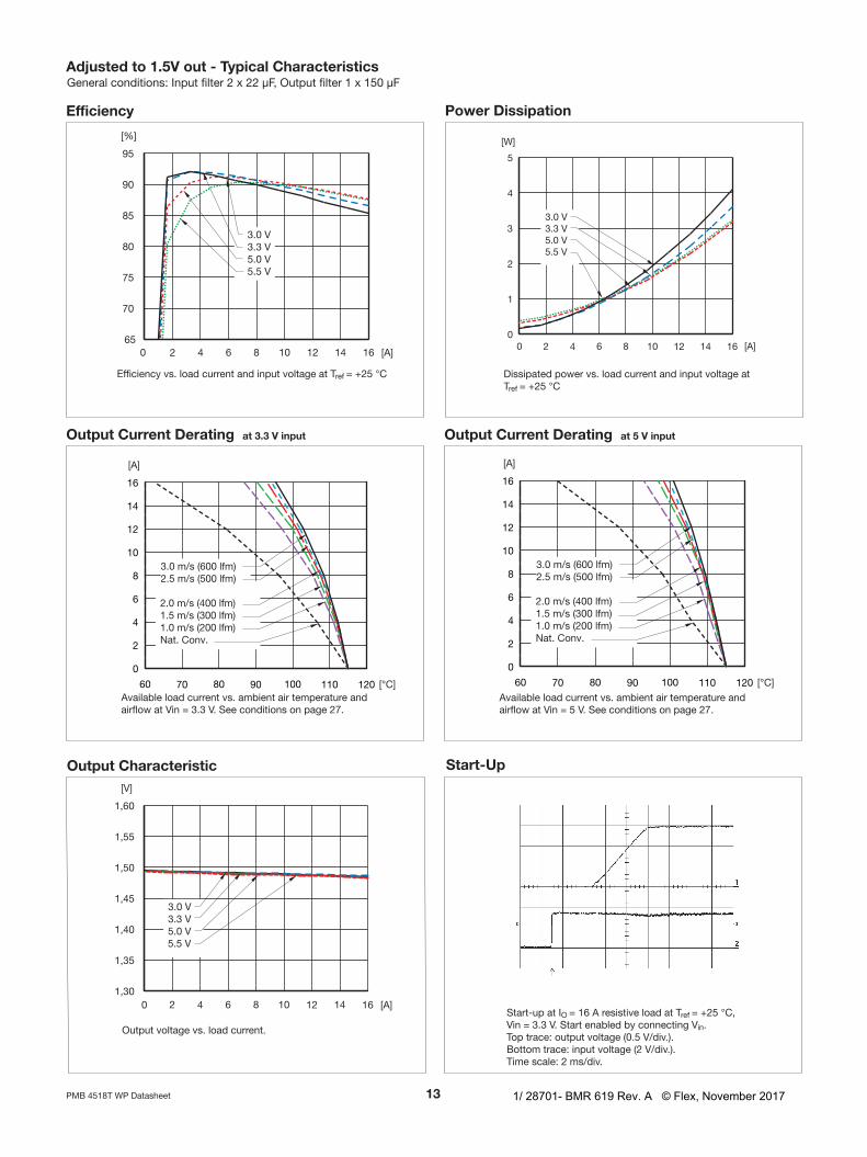
Tref=-30...+90°C,VI=3.0...5.5Vunlessotherwisespecified.Inputfilter2x22µF,Outputfilter1x150µFTypvaluesspecifiedat:Tref=+25°CandVInom.IOmax=16A.Note:+Senseconnectedto+Out
Adjusted to 1.0 V out - Data
1/ 28701- BMR 619 Rev. A © Flex, November 2017

PMB4518TWPDatasheet
Output Current Derating at V input
Start-Up
Outputvoltagevs.loadcurrent.
Availableloadcurrentvs.ambientairtemperatureandairflowatVin=5V.Seeconditionsonpage27.
Start-upatIO=16AresistiveloadatTref=+25°C,Vin=3.3V.StartenabledbyconnectingVin.Toptrace:outputvoltage(0.5V/div.).Bottomtrace:inputvoltage(2V/div.).Timescale:2ms/div.
Efficiency Power Dissipation
Output Characteristics
Adjusted to 1.0 V out - Typical Characteristics
Efficiencyvs.loadcurrentandinputvoltageatTref=+25°C Dissipatedpowervs.loadcurrentandinputvoltageatTref=+25°C
Generalconditions:Inputfilter2x22µF,Outputfilter1x150µF
Output Current Derating at . V input
Availableloadcurrentvs.ambientairtemperatureandairflowatVin=3.3V.Seeconditionsonpage27.
1/ 28701- BMR 619 Rev. A © Flex, November 2017

PMB4518TWPDatasheet
Turn Off Output Ripple
Transient with 10 µFoutputcapacitor
Outputvoltageresponsetoloadcurrentstep-change(4-12-4A)atTref=+25°C,Vin=3.3V.dI/dt=5A/µsToptrace:outputvoltage(ac)(100mV/div.).Bottomtrace:loadcurrent(dc)(10A/div.)Timescale:0.1ms/div.
Transient with 00 µFoutputcapacitor
Outputvoltageresponsetoloadcurrentstep-change(4-12-4A)atTref=+25°C,Vin=3.3V.dI/dt=5A/µsToptrace:outputvoltage(ac)(100mV/div.).Bottomtrace:loadcurrent(dc)(10A/div.)Timescale:0.1ms/div.
Outputvoltageripple(20mV/div.)atTref=+25°C,Vin=3.3V,IO=16Aresistiveload.Bandwidth=5MHz.Timescale:2µs/div.
Turn-offatIO=16AresistiveloadatTref=+25°C,Vin=3.3V.Turn-offenabledbydisconnectingVin.Toptrace:outputvoltage(0.5V/div.).Bottomtrace:inputvoltage(2V/div.).Timescale:2ms/div.
Adjusted to 1.0 V out - Typical CharacteristicsGeneralconditions:Inputfilter2x22µF,Outputfilter1x150µF
1/ 28701- BMR 619 Rev. A © Flex, November 2017

PMB4518TWPDatasheet
Tref=-30...+90°C,VI=3.0...5.5Vunlessotherwisespecified.Inputfilter2x22µF,Outputfilter1x150µFTypvaluesspecifiedat:Tref=+25°CandVInom,IOmax=16A.Note:+Senseconnectedto+Out
Adjusted to 1. V out - Data
Characteristics ConditionsOutput
Unitmin typ max
VOi Outputvoltageadjustedsetting Tref=+25°C,VInom,IOmax,Radj42kΩ 1.176 1.20 1.224 V
VO
Outputvoltagetoleranceband IO=0.01...1.0xIOmax 1.164 1.236 V
Idlingvoltage IO=0 1.18 1.22 V
Lineregulation VImin...VImax,IOmax 11 mV
Loadregulation IO=0.01...1.0xIOmax,VInom 10 mV
VtrLoadtransientvoltagedeviation
Loadstep=0.25...0.75xIOmax,dI/dt=5A/µs,CO=150µF,VI=3.3V
120 mV
ttr Loadtransientrecoverytime 60 µs
Tcoeff Temperaturecoefficient Tref=-30...+90°C,IOmax -0.1 0 +0.1 mV/°C
ts Start-uptimeFromVIconnectedtoVO=0.9xVOI,IO=0.1...1.0xIOmax,VInom
8.5 ms
tr Ramp-uptime 0.1...0.9xVO,IO=0.1...1.0xIOmax,VInom 4 ms
tr Falltime,VOx0.1 IO=IOmax,VInom 0.2 ms
tr Falltime,VOx0.1 IO=0A,VInom 5 s
tRCoff RCshut-downtimetoVOx0.1 IO=IOmax,VInom 0.2 ms
tRCon RCstart-uptimetoVOx0.9 IO=IOmax,VInom 8 ms
tRC RCfalltime,VOx0.1...0.9 IO=0A,VInom 5 s
IO Outputcurrent 0 16 A
POmax Maxoutputpower AtVO=VOnom 19.2 W
Ilim Currentlimitthreshold Tref<Trefmax 22 28 35 A
VOac Outputripple 20Hz...5MHz,IOmax 10 20 mVp-p
η Efficiency-50%load IO=0.5xIOmax,VI=5V 89 %
η Efficiency-100%load IO=IOmax,VI=5V 82.7 85.1 %
Pd PowerDissipation IO=IOmax,VI=5V 3.3 4.0 W
Fo Switchingfrequency IO=0...1.0xIOmax 260 300 340 kHz
Isense Remotesensecurrent 8 mA
II Staticinputcurrent VI=3.0V,IO=IOmax,Tref=25°C 7.8 A
MTBF Predictedreliability Tref=40°C 6millionhours
1/ 28701- BMR 619 Rev. A © Flex, November 2017

10PMB4518TWPDatasheet
Output Current Derating at V input
Output Characteristic Start-Up
Outputvoltagevs.loadcurrent.
Availableloadcurrentvs.ambientairtemperatureandairflowatVin=5V.Seeconditionsonpage27.
Start-upatIO=16AresistiveloadatTref=+25°C,Vin=3.3V.StartenabledbyconnectingVin.Toptrace:outputvoltage(0.5V/div.).Bottomtrace:inputvoltage(2V/div.).Timescale:2ms/div.
Efficiency Power Dissipation
Adjusted to 1. V - Typical Characteristics
Efficiencyvs.loadcurrentandinputvoltageatTre=+25°C Dissipatedpowervs.loadcurrentandinputvoltageatTref=+25°C
Generalconditions:Inputfilter2x22µF,Outputfilter1x150µF
Output Current Derating at . V input
Availableloadcurrentvs.ambientairtemperatureandairflowatVin=3.3V.Seeconditionsonpage27.
1/ 28701- BMR 619 Rev. A © Flex, November 2017

11PMB4518TWPDatasheet
Turn Off Output Ripple
Transient with 10 µFoutputcapacitor
Outputvoltageresponsetoloadcurrentstep-change(4-12-4A)atTref=+25°C,Vin=3.3V.dI/dt=5A/µsToptrace:outputvoltage(ac)(100mV/div.).Bottomtrace:loadcurrent(dc)(10A/div.)Timescale:0.1ms/div.
Transient with 00 µFoutputcapacitor
Outputvoltageresponsetoloadcurrentstep-change(4-12-4A)atTref=+25°C,Vin=3.3V.dI/dt=5A/µsToptrace:outputvoltage(ac)(100mV/div.).Bottomtrace:loadcurrent(dc)(10A/div.)Timescale:0.1ms/div.
Outputvoltageripple(20mV/div.)atTref=+25°C,Vin=3.3V,IO=16Aresistiveload.Bandwidth=5MHz.Timescale:2µs/div.
Turn-offatIO=16AresistiveloadatTref=+25°C,Vin=3.3V.Turn-offenabledbydisconnectingVin.Toptrace:outputvoltage(0.5V/div.).Bottomtrace:inputvoltage(2V/div.).Timescale:2ms/div.
Adjusted to 1. V - Typical CharacteristicsGeneralconditions:Inputfilter2x22µF,Outputfilter1x150µF
1/ 28701- BMR 619 Rev. A © Flex, November 2017

1PMB4518TWPDatasheet
Characteristics ConditionsOutput
Unitmin typ max
VOi Outputvoltageadjustedsetting Tref=+25°C,VInom,IOmax,Radj23kΩ 1.47 1.5 1.53 V
VO
Outputvoltagetoleranceband IO=0.01...1.0xIOmax 1.455 1.545 V
Idlingvoltage IO=0 1.48 1.52 V
Lineregulation VImin...VImax,IOmax 11 mV
Loadregulation IO=0.01...1.0xIOmax,VInom 10 mV
VtrLoadtransientvoltagedeviation
Loadstep=0.25...0.75xIOmax,dI/dt=5A/µs,CO=150µF,VI=3.3V
120 mV
ttr Loadtransientrecoverytime 60 µs
Tcoeff Temperaturecoefficient Tref=-30...+90°C,IOmax -0.1 0 +0.1 mV/°C
ts Start-uptimeFromVIconnectedtoVO=0.9xVOI,IO=0.1...1.0xIOmax,VInom
8.5 ms
tr Ramp-uptime 0.1...0.9xVO,IO=0.1...1.0xIOmax,VInom 4 ms
tr Falltime,VOx0.1 IO=IOmax,VInom 0.2 ms
tr Falltime,VOx0.1 IO=0A,VInom 5 s
tRCoff RCshut-downtimetoVOx0.1 IO=IOmax,VInom 0.2 ms
tRCon RCstart-uptimetoVOx0.9 IO=IOmax,VInom 8 ms
tRC RCfalltime,VOx0.1...0.9 IO=0A,VInom 5 s
IO Outputcurrent 0 16 A
POmax Maxoutputpower AtVO=VOnom 24 W
Ilim Currentlimitthreshold Tref<Trefmax 22 28 35 A
VOac Outputripple 20Hz...5MHz,IOmax 10 20 mVp-p
η Efficiency-50%load IO=0.5xIOmax,VI=5V 91 %
η Efficiency-100%load IO=IOmax,VI=5V 85.5 87.7 %
Pd PowerDissipation IO=IOmax,VI=5V 3.2 4.1 W
Fo Switchingfrequency IO=0...1.0xIOmax 260 300 340 kHz
Isense Remotesensecurrent 8 mA
II Staticinputcurrent VI=3.0V,IO=IOmax,Tref=25°C 9.5 A
MTBF Predictedreliability Tref=40°C 6millionhours
Tref=-30...+90°C,VI=3.0...5.5Vunlessotherwisespecified.Inputfilter2x22µF,Outputfilter1x150µFTypvaluesspecifiedat:Tref=+25°CandVInom.IOmax=16A.Note:+Senseconnectedto+Out
Adjusted to 1. V out - Data
1/ 28701- BMR 619 Rev. A © Flex, November 2017
1PMB4518TWPDatasheet
Output Current Derating at V input
Output Characteristic Start-Up
Outputvoltagevs.loadcurrent.
Availableloadcurrentvs.ambientairtemperatureandairflowatVin=5V.Seeconditionsonpage27.
Start-upatIO=16AresistiveloadatTref=+25°C,Vin=3.3V.StartenabledbyconnectingVin.Toptrace:outputvoltage(0.5V/div.).Bottomtrace:inputvoltage(2V/div.).Timescale:2ms/div.
Efficiency Power Dissipation
Adjusted to 1.V out - Typical Characteristics
Efficiencyvs.loadcurrentandinputvoltageatTref=+25°C Dissipatedpowervs.loadcurrentandinputvoltageatTref=+25°C
Generalconditions:Inputfilter2x22µF,Outputfilter1x150µF
Output Current Derating at . V input
Availableloadcurrentvs.ambientairtemperatureandairflowatVin=3.3V.Seeconditionsonpage27.
1/ 28701- BMR 619 Rev. A © Flex, November 2017

1PMB4518TWPDatasheet
Turn Off Output Ripple
Transient with 10 µFoutputcapacitor
Outputvoltageresponsetoloadcurrentstep-change(4-12-4A)atTref=+25°C,Vin=3.3V.dI/dt=5A/µsToptrace:outputvoltage(ac)(100mV/div.).Bottomtrace:loadcurrent(dc)(10A/div.)Timescale:0.1ms/div.
Transient with 00 µFoutputcapacitor
Outputvoltageresponsetoloadcurrentstep-change(4-12-4A)atTref=+25°C,Vin=3.3V.dI/dt=5A/µsToptrace:outputvoltage(ac)(100mV/div.).Bottomtrace:loadcurrent(dc)(10A/div.)Timescale:0.1ms/div.
Outputvoltageripple(20mV/div.)atTref=+25°C,Vin=3.3V,IO=16Aresistiveload.Bandwidth=5MHz.Timescale:2µs/div.
Turn-offatIO=16AresistiveloadatTref=+25°C,Vin=3.3V.Turn-offenabledbydisconnectingVin.Toptrace:outputvoltage(0.5V/div.).Bottomtrace:inputvoltage(2V/div.).Timescale:2ms/div.
Adjusted to 1.V out - Typical CharacteristicsGeneralconditions:Inputfilter2x22µF,Outputfilter1x150µF
1/ 28701- BMR 619 Rev. A © Flex, November 2017

1PMB4518TWPDatasheet
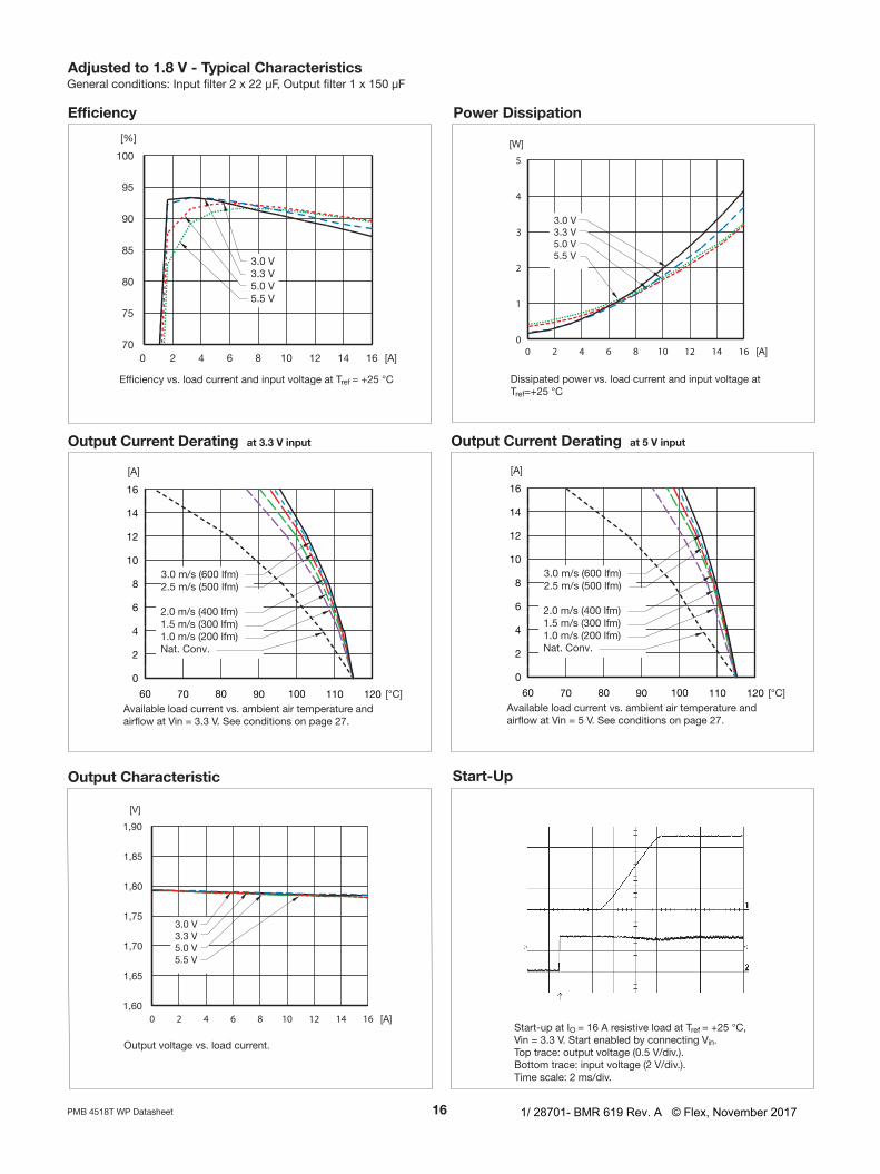
Tref=–30…+90°C,VI=3.0...5.5Vunlessotherwisespecified.Inputfilter2x22µF,Outputfilter1x150µFTypvaluesspecifiedat:Tref=+25°CandVInom.IOmax=16A.Note:+Senseconnectedto+Out
Adjusted to 1. V out - Data
Characteristics ConditionsOutput
Unitmin typ max
VOi Outputvoltageadjustedsetting Tref=+25°C,VInom,IOmax,Radj15kΩ 1.764 1.80 1.836 V
VO
Outputvoltagetoleranceband IO=0.01...1.0xIOmax 1.746 1.854 V
Idlingvoltage IO=0 1.78 1.82 V
Lineregulation VImin...VImax,IOmax 11 mV
Loadregulation IO=0.01...1.0xIOmax,VInom 10 mV
VtrLoadtransientvoltagedeviation
Loadstep=0.25...0.75xIOmax,dI/dt=5A/µs,CO=150µF,VI=3.3V
110 mV
ttr Loadtransientrecoverytime 60 µs
Tcoeff Temperaturecoefficient Tref=-30...+90°C,IOmax -0.1 0 +0.1 mV/°C
ts Start-uptimeFromVIconnectedtoVO=0.9xVOI,IO=0.1...1.0xIOmax,VInom
8.5 ms
tr Ramp-uptime 0.1...0.9xVO,IO=0.1...1.0xIOmax,VInom 4 ms
tr Falltime,VOx0.1 IO=IOmax,VInom 0.2 ms
tr Falltime,VOx0.1 IO=0A,VInom 5 s
tRCoff RCshut-downtimetoVOx0.1 IO=IOmax,VInom 0.2 ms
tRCon RCstart-uptimetoVOx0.9 IO=IOmax,VInom 8 ms
tRC RCfalltime,VOx0.1...0.9 IO=0A,VInom 5 s
IO Outputcurrent 0 16 A
POmax Maxoutputpower AtVO=VOnom 28.8 W
Ilim Currentlimitthreshold Tref<Trefmax 22 28 35 A
VOac Outputripple 20Hz...5MHz,IOmax 14 24 mVp-p
η Efficiency-50%load IO=0.5xIOmax,VI=5V 92 %
η Efficiency-100%load IO=IOmax,VI=5V 88.5 89.8 %
Pd PowerDissipation IO=IOmax,VI=5V 3.3 3.8 W
Fo Switchingfrequency IO=0...1.0xIOmax 260 300 340 kHz
Isense Remotesensecurrent 8 mA
II Staticinputcurrent VI=3.0V,IO=IOmax,Tref=25°C 10.9 A
MTBF Predictedreliability Tref=40°C 6millionhours
1/ 28701- BMR 619 Rev. A © Flex, November 2017
1PMB4518TWPDatasheet
Efficiency
Output Current Derating at . V input Output Current Derating at V input
Adjusted to 1. V - Typical Characteristics
Output Characteristic Start-Up
Outputvoltagevs.loadcurrent.
Availableloadcurrentvs.ambientairtemperatureandairflowatVin=5V.Seeconditionsonpage27.
Efficiencyvs.loadcurrentandinputvoltageatTref=+25°C
Start-upatIO=16AresistiveloadatTref=+25°C,Vin=3.3V.StartenabledbyconnectingVin.Toptrace:outputvoltage(0.5V/div.).Bottomtrace:inputvoltage(2V/div.).Timescale:2ms/div.
Availableloadcurrentvs.ambientairtemperatureandairflowatVin=3.3V.Seeconditionsonpage27.
Power Dissipation
Dissipatedpowervs.loadcurrentandinputvoltageatTref=+25°C
Generalconditions:Inputfilter2x22µF,Outputfilter1x150µF
1/ 28701- BMR 619 Rev. A © Flex, November 2017

1PMB4518TWPDatasheet
Turn Off Output Ripple
Adjusted to 1. V out - Typical Characteristics
Transient with 10 µFoutputcapacitor
Outputvoltageresponsetoloadcurrentstep-change(4-12-4A)atTref=+25°C,Vin=3.3V.dI/dt=5A/µsToptrace:outputvoltage(ac)(100mV/div.).Bottomtrace:loadcurrent(dc)(10A/div.)Timescale:0.1ms/div.
Transient with 00 µFoutputcapacitor
Outputvoltageresponsetoloadcurrentstep-change(4-12-4A)atTref=+25°C,Vin=3.3V.dI/dt=5A/µsToptrace:outputvoltage(ac)(100mV/div.).Bottomtrace:loadcurrent(dc)(10A/div.)Timescale:0.1ms/div.
Outputvoltageripple(20mV/div.)atTref=+25°C,Vin=3.3V,IO=16Aresistiveload.Bandwidth=5MHz.Timescale:2µs/div.
Turn-offatIO=16AresistiveloadatTref=+25°C,Vin=3.3V.Turn-offenabledbydisconnectingVin.Toptrace:outputvoltage(0.5V/div.).Bottomtrace:inputvoltage(2V/div.).Timescale:2ms/div.
Generalconditions:Inputfilter2x22µF,Outputfilter1x150µF
1/ 28701- BMR 619 Rev. A © Flex, November 2017

1PMB4518TWPDatasheet
Characteristics ConditionsOutput
Unitmin typ max
VOi Outputvoltageadjustedsetting Tref=+25°C,VInom,IOmax,Radj7kΩ 2.45 2.5 2.55 V
VO
Outputvoltagetoleranceband IO=0.01...1.0xIOmax 2.425 2.575 V
Idlingvoltage IO=0 2.48 2.52 V
Lineregulation VImin...VImax,IOmax 11 mV
Loadregulation IO=0.01...1.0xIOmax,VInom 10 mV
VtrLoadtransientvoltagedeviation
Loadstep=0.25...0.75xIOmax,dI/dt=5A/µs,CO=150µF,VI=3.3V
160 mV
ttr Loadtransientrecoverytime 60 µs
Tcoeff Temperaturecoefficient Tref=-30...+90°C,IOmax -0.1 0 +0.1 mV/°C
ts Start-uptimeFromVIconnectedtoVO=0.9xVOI,IO=0.1...1.0xIOmax,VInom
8.5 ms
tr Ramp-uptime 0.1...0.9xVO,IO=0.1...1.0xIOmax,VInom 4 ms
tr Falltime,VOx0.1 IO=IOmax,VInom 0.2 ms
tr Falltime,VOx0.1 IO=0A,VInom 5 s
tRCoff RCshut-downtimetoVOx0.1 IO=IOmax,VInom 0.2 ms
tRCon RCstart-uptimetoVOx0.9 IO=IOmax,VInom 8 ms
tRC RCfalltime,VOx0.1...0.9 IO=0A,VInom 5 s
IO Outputcurrent 0 16 A
POmax Maxoutputpower AtVO=VOnom 40 W
Ilim Currentlimitthreshold Tref<Trefmax 22 28 35 A
VOac Outputripple 20Hz...5MHz,IOmax 20 35 mVp-p
η Efficiency-50%load IO=0.5xIOmax,VI=5V 94 %
η Efficiency-100%load IO=IOmax,VI=5V 90 92 %
Pd PowerDissipation IO=IOmax,VI=5V 3.4 4.5 W
Fo Switchingfrequency IO=0...1.0xIOmax 260 300 340 kHz
Isense Remotesensecurrent 8 mA
II Staticinputcurrent VI=3.0V,IO=IOmax,Tref=25°C 15.1 A
MTBF Predictedreliability Tref=40°C 6millionhours
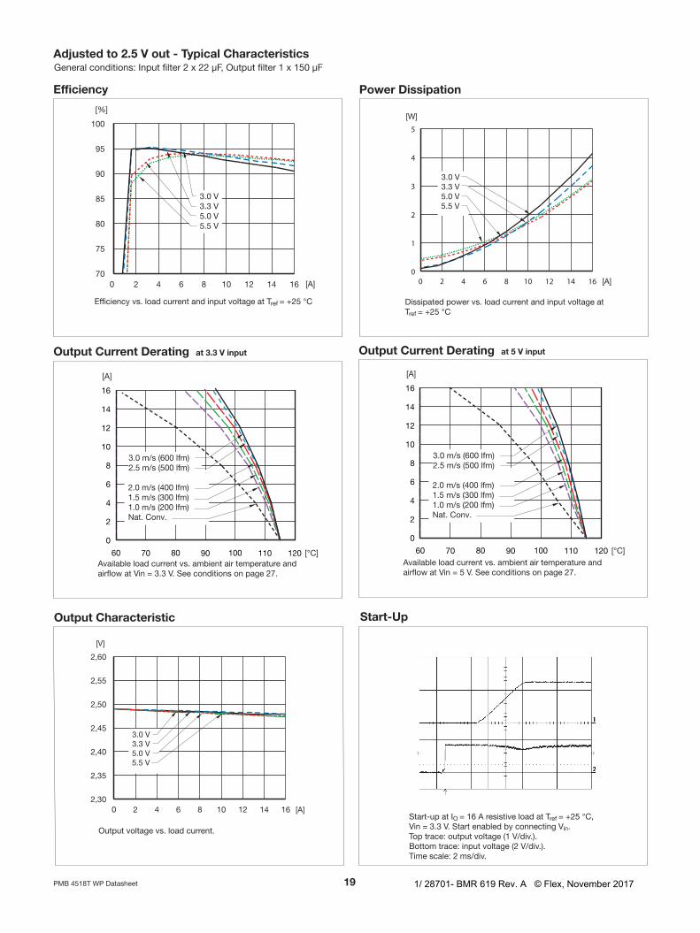
Tref=-30...+90°C,VI=3.0...5.5Vunlessotherwisespecified.Inputfilter2x22µF,Outputfilter1x150µFTypvaluesspecifiedat:Tref=+25°CandVInom.IOmax=16A.Note:+Senseconnectedto+Out
Adjusted to . V out - Data
1/ 28701- BMR 619 Rev. A © Flex, November 2017
1PMB4518TWPDatasheet
Output Current Derating at V input
Output Characteristic Start-Up
Outputvoltagevs.loadcurrent.
Availableloadcurrentvs.ambientairtemperatureandairflowatVin=5V.Seeconditionsonpage27.
Start-upatIO=16AresistiveloadatTref=+25°C,Vin=3.3V.StartenabledbyconnectingVin.Toptrace:outputvoltage(1V/div.).Bottomtrace:inputvoltage(2V/div.).Timescale:2ms/div.
Efficiency Power Dissipation
Adjusted to . V out - Typical Characteristics
Efficiencyvs.loadcurrentandinputvoltageatTref=+25°C Dissipatedpowervs.loadcurrentandinputvoltageatTref=+25°C
Generalconditions:Inputfilter2x22µF,Outputfilter1x150µF
Output Current Derating at . V input
Availableloadcurrentvs.ambientairtemperatureandairflowatVin=3.3V.Seeconditionsonpage27.
1/ 28701- BMR 619 Rev. A © Flex, November 2017

0PMB4518TWPDatasheet
Turn Off Output Ripple
Transient with 10 µFoutputcapacitor
Outputvoltageresponsetoloadcurrentstep-change(4-12-4A)atTref=+25°C,Vin=3.3V.dI/dt=5A/µsToptrace:outputvoltage(ac)(100mV/div.).Bottomtrace:loadcurrent(dc)(10A/div.)Timescale:0.1ms/div.
Transient with 00 µFoutputcapacitor
Outputvoltageresponsetoloadcurrentstep-change(4-12-4A)atTref=+25°C,Vin=3.3V.dI/dt=5A/µsToptrace:outputvoltage(ac)(100mV/div.).Bottomtrace:loadcurrent(dc)(10A/div.)Timescale:0.1ms/div.
Outputvoltageripple(20mV/div.)atTref=+25°C,Vin=3.3V,IO=16Aresistiveload.Bandwidth=5MHz.Timescale:2µs/div.
Turn-offatIO=16AresistiveloadatTref=+25°C,Vin=3.3V.Turn-offenabledbydisconnectingVin.Toptrace:outputvoltage(1V/div.).Bottomtrace:inputvoltage(2V/div.).Timescale:2ms/div.
Adjusted to . V out - Typical CharacteristicsGeneralconditions:Inputfilter2x22µF,Outputfilter1x150µF
1/ 28701- BMR 619 Rev. A © Flex, November 2017

1PMB4518TWPDatasheet
Tref=-30...+90°C,VI=3.8...5.5Vunlessotherwisespecified.Inputfilter2x22µF,Outputfilter1x150µFTypvaluesspecifiedat:Tref=+25°CandVI=5.0V.IOmax=16A.Note:+Senseconnectedto+Out
Adjusted to . V out - Data
Characteristics ConditionsOutput
Unitmin typ max
VOi Outputvoltageadjustedsetting Tref=+25°C,VI>3.8V,IOmax,Radj3.1kΩ 3.234 3.3 3.366 V
VO
Outputvoltagetoleranceband IO=0.1...1.0xIOmax 3.201 3.399 V
Idlingvoltage IO=0 3.28 3.32 V
Lineregulation VI=5V...VImax,IOmax 11 mV
Loadregulation IO=0.01...1.0xIOmax,VI=5V 20 mV
VtrLoadtransientvoltagedeviation
Loadstep=0.25...0.75xIOmax,dI/dt=5A/µs,CO=150µF,VI=5V
120 mV
ttr Loadtransientrecoverytime 60 µs
Tcoeff Temperaturecoefficient Tref=-30...+90°C,IOmax -0.1 0 +0.1 mV/°C
ts Start-uptimeFromVIconnectedtoVO=0.9xVOadj,IO=0.1...1.0xIOmax,VI=5V
8.5 ms
tr Ramp-uptime0.1...0.9xVO,IO=0.1...1.0xIOmax,VI=5V
4 ms
tr Falltime,VOx0.1 IO=IOmax,VI=5V 0.2 ms
tr Falltime,VOx0.1 IO=0A,VI=5V 5 s
tRCoff RCshut-downtimetoVOx0.1 IO=IOmax,VI=5V 0.2 ms
tRCon RCstart-uptimetoVOx0.9 IO=IOmax,VI=5V 8 ms
tRC RCfalltime,VOx0.1...0.9 IO=0A,VI=5V 5 s
IO Outputcurrent 0 16 A
POmax Maxoutputpower AtVO=VOnom 52.8 W
Ilim Currentlimitthreshold Tref<Trefmax 22 25 35 A
VOac Outputripple 20Hz...5MHz,IOmax 25 40 mVp-p
η Efficiency-50%load IO=0.5xIOmax,VI=5V 95.4 %
η Efficiency-100%load IO=IOmax,VI=5V 92 94 %
Pd PowerDissipation IO=IOmax,VI=5V 3.2 4.6 W
Fo Switchingfrequency IO=0...1.0xIOmax 260 300 340 kHz
Isense Remotesensecurrent 8 mA
II Staticinputcurrent VI=3.8V,IO=IOmax,Tref=25°C 15.0 A
MTBF Predictedreliability Tref=40°C 6millionhours
1/ 28701- BMR 619 Rev. A © Flex, November 2017

PMB4518TWPDatasheet
Output Current Derating at V inputOutput Characteristic
Start-Up
Outputvoltagevs.loadcurrent. Availableloadcurrentvs.ambientairtemperatureandairflowatVin=5V.Seeconditionsonpage27.
Start-upatIO=16AresistiveloadatTref=+25°C,Vin=5V.StartenabledbyconnectingVin.Toptrace:outputvoltage(1V/div.).Bottomtrace:inputvoltage(2V/div.).Timescale:2ms/div.
Efficiency Power Dissipation
Adjusted to . V out - Typical Characteristics
Efficiencyvs.loadcurrentandinputvoltageatTref=+25°C Dissipatedpowervs.loadcurrentandinputvoltageatTref=+25°C
Generalconditions:Inputfilter2x22µF,Outputfilter1x150µF
Turn Off
Turn-offatIO=16AresistiveloadatTref=+25°C,Vin=5V.Turn-offenabledbydisconnectingVin.Toptrace:outputvoltage(1V/div.).Bottomtrace:inputvoltage(2V/div.).Timescale:2ms/div.
1/ 28701- BMR 619 Rev. A © Flex, November 2017

PMB4518TWPDatasheet
Output Ripple Transient with 10 µFoutputcapacitor
Outputvoltageresponsetoloadcurrentstep-change(4-12-4A)atTref=+25°C,Vin=5V.dI/dt=5A/µsToptrace:outputvoltage(ac)(100mV/div.).Bottomtrace:loadcurrent(dc)(10A/div.)Timescale:0.1ms/div.
Transient with 00 µFoutputcapacitor
Outputvoltageresponsetoloadcurrentstep-change(4-12-4A)atTref=+25°C,Vin=5V.dI/dt=5A/µsToptrace:outputvoltage(ac)(100mV/div.).Bottomtrace:loadcurrent(dc)(10A/div.)Timescale:0.1ms/div.
Outputvoltageripple(20mV/div.)atTref=+25°C,Vin=5V,IO=16Aresistiveload.Bandwidth=5MHz.Timescale:2µs/div.
Adjusted to . V out - Typical CharacteristicsGeneralconditions:Inputfilter2x22µF,Outputfilter1x150µF
1/ 28701- BMR 619 Rev. A © Flex, November 2017

PMB4518TWPDatasheet
RCRegulatorcondition
min typ max Unit
HighlevelreferencedtoGND
OFF 1.7 5.5 V
Open ON
EMC Specification
Layout Recommendation TheradiatedEMIperformanceoftheDC/DCregulatorwillbeoptimisedbyincludingagroundplaneinthePCBareaundertheDC/DCregulator.Thisapproachwillreturnswitchingnoisetogroundasdirectlyaspossible,withimprovementstobothemissionandsusceptibility.
Operating Information
Remote Control (RC)TheRCpinmaybeusedtoturnonorturnofftheregulatorusingasuitableopencollectorfunction.TurnoffisachievedbyconnectingtheRCpintotheinputvoltage.
TheregulatorwillruninnormaloperationwhentheRCpinisleftopen.
AllPMB4000SeriesDC/DCregulatorshaveapositivere-motesensepinthatcanbeusedtocompensateformoder-ateamountsofresistanceinthedistributionsystemandal-lowforvoltageregulationattheloadorotherselectedpoint.Theremotesenselinewillcarryverylittlecurrentanddoesnotneedalargecrosssectionalarea.However,thesenselineonthePCBshouldbelocatedclosetoagroundtraceorgroundplane.Theremotesensecircuitrywillcompensateforupto10%voltagedropbetweenthesensevoltageandthevoltageattheoutputpinsfromVOnom.Iftheremotesenseisnotneededthesensepinshouldbeleftopen.
Remote Sense
RC
Vi
Module
Vi
GND
1/ 28701- BMR 619 Rev. A © Flex, November 2017

PMB4518TWPDatasheet
Input And Output Impedance
Operating Information
Output Voltage Adjust (Vadj)
Theoutputvoltagecanbesetbymeansofanexternalresistor,connectedtotheVadjpin.Nominaloutputvoltage0.75VissetbyleavingtheVadjpinopen.Adjustmentcanonlybemadetoincreasetheoutputvoltagesetting.
Toincrease:Connectaresistorbetween(Vadj)and(Gnd).Theoutputvoltageincreaseswithdecreasingresistorvalueasshowninthetablebelow.Notethatthemaximumoutputvoltage3.63Vmaynotbeexceeded.
Rextup(kohm)=(21.007/(VO-0.75225))-5.1
Circuitconfigurationforoutputvoltageadjust
Increase
+Out
GND
VadjLoad
Radj
Sense
OutputVoltage(V) Resistor(ohm)
0.75 Open
1.0 79.691k
1.2 41.817k
1.5 22.990k
1.8 14.949k
2.5 6.919k
3.3 3.145k
Current Limit Protection ThePMB4000SeriesDC/DCregulatorsincludecurrentlimitingcircuitrythatallowsthemtowithstandcontinuousoverloadsorshortcircuitconditionsontheoutput.Thecur-rentlimitisofhick-upmodetype.Theregulatorwillresumenormaloperationafterremovaloftheoverload.Theloaddistributionsystemshouldbedesignedtocarrythemaximumoutputshortcircuitcurrentspecified.
Input And Output ImpedanceTheimpedanceofboththepowersourceandtheloadwillinteractwiththeimpedanceoftheDC/DCregulator.Itismostimportanttohavealowcharacteristicimpedance,bothattheinputandoutput,astheregulatorshavealowenergystoragecapability.Usecapacitorsacrosstheinputifthesourceinductanceisgreaterthan4.7µH.Suitableinputcapacitorsare22µF-220µFlowESRceramics.
Maximum Capacitive LoadWhenpoweringloadswithsignificantdynamiccurrentrequirements,thevoltageregulationattheloadcanbeimprovedbyadditionofdecouplingcapacitanceattheload.ThemosteffectivetechniqueistolocatelowESRceramiccapacitorsasclosetotheloadaspossible,usingseveralcapacitorstolowerthetotalESR.Theseceramiccapacitorswillhandleshortdurationhigh-frequencycomponentsofdynamicloadchanges.Inaddition,highervaluesofcapacitors(electrolyticcapacitors)shouldbeusedtohandlethemid-frequencycomponents.ItisequallyimportanttousegooddesignpracticewhenconfiguringtheDCdistributionsystem.
LowresistanceandlowinductancePCBlayoutsandcablingshouldbeused.Rememberthatwhenusingremotesensing,allresistance(includingtheESR),inductanceandcapacitanceofthedistributionsystemiswithinthefeedbackloopoftheregulator.Thiscanaffectontheregulatorscompensationandtheresultingstabilityanddynamicresponseperformance.
VerylowESRandhighcapacitancemustbeusedwithcare.A“ruleofthumb”isthatthetotalcapacitancemustneverexceedtypically500-700µFifonlylowESR(<2mΩ)ceramiccapacitorsareused.Ifmorecapacitanceisneeded,acombinationoflowESRtypeandelectrolyticcapacitorsshouldbeused,otherwisethestabilitywillbeaffected.
ThePMB4000seriesregulatorcanacceptupto8mFofcapacitiveloadontheoutputatfullload.Thisgives<500µF/AofIO.Whenusingthatlargecapacitanceitisimportanttoconsidertheselectionofoutputcapacitors;theresultingbehaviorisacombinationoftheamountofcapacitanceandESR.
Minimum Required External Capacitors
Externalinputcapacitorsarerequiredtoincreasethelifetimeoftheinternalcapacitorsandtofurtherreducetheinputripple.Aminimumof2x22µF external input capaci-µF external input capaci-Fexternalinputcapaci-tancewithlowESRshouldbeadded.
Aminimumof150µF external output capacitance, low ESR,µF external output capacitance, low ESR,Fexternaloutputcapacitance,lowESR,shouldbeaddedfortheconvertertooperateproperlyatfullload.
1/ 28701- BMR 619 Rev. A © Flex, November 2017

PMB4518TWPDatasheet
Operating Information
Parallel OperationThePMB4000SeriesDC/DCregulatorscanbeconnectedinparallelwithacommoninput.Parallelingisaccomplishedbyconnectingtheoutputvoltagepinsdirectlyandusingaloadsharingdeviceontheinput.Layoutconsiderationsshouldbemadetoavoidloadimbalance.Formoredetailsonparallel-
ing,pleaseconsultyourlocalapplicationssupport.
Input Undervoltage LockoutThePMB4000SeriesDC/DCregulatorsareequippedwithalockoutfunctionforlowinputvoltage.Whentheinputvoltageisbelowtheundervoltagelockoutlimitoftheregulatoritwillshutoff.Whentheinputvoltageincreasesabovethelockout
leveltheregulatorwillturnon.
AcombinationoflowESRandoutputcapacitanceexceeding8mFcancausetheregulatorintoovercurrentprotectionmode(hick-up)duetohighstartupcurrent.TheoutputfiltermustthereforebedesignedwithoutexceedingtheabovestatedcapacitancelevelsiftheESRislowerthan30-40mΩ.
1/ 28701- BMR 619 Rev. A © Flex, November 2017

PMB4518TWPDatasheet
Thermal Considerations
GeneralThePMB4000SeriesDC/DCregulatorsaredesignedtooperateinavarietyofthermalenvironments,howeversufficientcoolingshouldbeprovidedtohelpensurereliableoperation.Heatisremovedbyconduction,convectionandradiationtothesurroundingenvironment.Increasedairflowenhancestheheattransferviaconvection.Propercoolingcanbeverifiedbymeasuringthetemperatureatthereferencepoint(Tref).
Calculation of ambient temperature
Byusingthethermalresistancethemaximumallowedambienttemperaturecanbecalculated.
A.Thepowerlossiscalculatedbyusingtheformula((1/η )-1)×outputpower=powerlosses.η=efficiencyofregulator.Example:95%=0.95
B.FindthevalueofthethermalresistanceRthTref-Ainthedia-grambyusingtheairflowspeedatthemodule.Takethether-malresistance×powerlosstogetthetemperatureincrease.
Thermalresistancevs.airspeedmeasuredattheregulator.
C.Maxallowedcalculatedambienttemperatureis:MaxTrefofDC/DCregulator-temperatureincrease.
Example:5Vinput,1.8Voutputat1m/s,fullload:
B. 3.2W×9°C/W=28.8°C
C. 90°C-28.8°C=maxambienttemperatureis61.2°C
Therealtemperaturewillbedependentonseveralfactors,likePCBsizeandtype,directionofairflow,airturbulenceetc.Itisrecommendedtoverifythetemperaturebytesting.
A. ((1/0.9)-1)×28.8W=3.2W
ThePMB4000thermaltestingisperformedwiththeproductmountedonanFR4board254× 254 mm with 8× 254 mm with 8254mmwith8layersof35µm copper. Airflow is perpendicular to the Tµm copper. Airflow is perpendicular to the Tmcopper.AirflowisperpendiculartotheTrefside.
25m
m[1
in.]
airflow
Test board
choke
1/ 28701- BMR 619 Rev. A © Flex, November 2017

PMB4518TWPDatasheet
Soldering InformationThePMB4000seriesDC/DCregulatorsareintendedformanualorwavesoldering.Theplasticbodyofthepinconnectorsresistssolderingheatforlimitedtimeupto260°C..
Whenhandsoldering,careshouldbetakentoavoiddirectcontactbetweenthehotsolderingirontipandthepinsformorethanafewsecondsinordertoavoidmeltingoftheplastic.
Delivery Package InformationThePMB4000seriesregulatorsaredeliveredinantistatictrayswithJedecstandardouterdimensions.Traycapacity25pcs.Eachboxcontains4trays.
ReliabilityTheMeanTimeBetweenFailure(MTBF)ofthePMB4000seriesDC/DCregulatorfamilyiscalculatedtobegreaterthan6millionhoursatfulloutputpowerandareferencetemperatureof+40°CusingTelCordiaSR332.
Compatibility with RoHS requirementsThe products are compatible with the relevant clauses and requirements of the RoHS directive 2011/65/EU and have a maximum concentration value of 0.1% by weight in homogeneous materials for lead, mercury, hexavalent chromium, PBB and PBDE and of 0.01% by weight in homogeneous materials for cadmium.
Exemptions in the RoHS directive utilized in Flex products are found in the Statement of Compliance document.
Flex fulfills and will continuously fulfill all its obligations under regulation (EC) No 1907/2006 concerning the registration, evaluation, authorization and restriction of chemicals (REACH) as they enter into force and is through product materials declarations preparing for the obligations to communicate information on substances in the products.
© Flex 2017
The information and specifications in this technical specification is believed to be correct at the time of publication. However, no liability is accepted for inaccuracies, printing errors or for any consequences thereof. Flex reserves the right to change thecontents of this technical specification at any time without prior notice.
1/ 28701- BMR 619 Rev. A © Flex, November 2017