DC/AC True RMS Voltage Data Logger Model L261 · Title: DC/AC True RMS Voltage Data Logger Model...
7
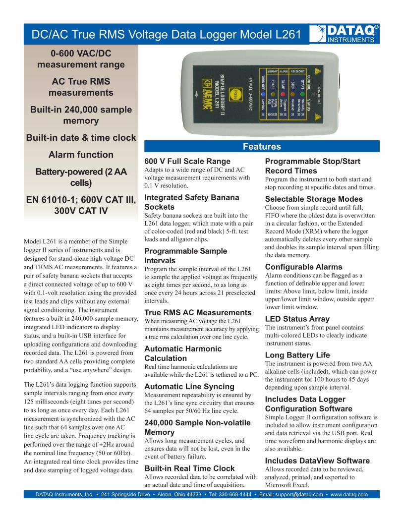
0-600 VAC/DC measurement range AC True RMS measurements Built-in 240,000 sample memory Built-in date & time clock Alarm function Battery-powered (2 AA cells) EN 61010-1; 600V CAT III, 300V CAT IV DC/AC True RMS Voltage Data Logger Model L261 DATAQ Instruments, Inc. • 241 Springside Drive • Akron, Ohio 44333 • Tel: 330-668-1444 • Email: [email protected]m • www.dataq.com Model L261 is a member of the Simple logger II series of instruments and is designed for stand-alone high voltage DC and TRMS AC measurements. It features a pair of safety banana sockets that accepts a direct connected voltage of up to 600 V with 0.1-volt resolution using the provided test leads and clips without any external signal conditioning. The instrument features a built in 240,000-sample memory, integrated LED indicators to display status, and a built-in USB interface for uploading configurations and downloading recorded data. The L261 is powered from two standard AA cells providing complete portability, and a “use anywhere” design. The L261’s data logging function supports sample intervals ranging from once every 125 milliseconds (eight times per second) to as long as once every day. Each L261 measurement is synchronized with the AC line such that 64 samples over one AC line cycle are taken. Frequency tracking is performed over the range of ±2Hz around the nominal line frequency (50 or 60Hz). An integrated real time clock provides time and date stamping of logged voltage data. 600 V Full Scale Range Adapts to a wide range of DC and AC voltage measurement requirements with 0.1 V resolution. Integrated Safety Banana Sockets Safety banana sockets are built into the L261 data logger, which mate with a pair of color-coded (red and black) 5-ft. test leads and alligator clips. Programmable Sample Intervals Program the sample interval of the L261 to sample the applied voltage as frequently as eight times per second, to as long as once every 24 hours across 21 preselected intervals. True RMS AC Measurements When measuring AC voltage the L261 maintains measurement accuracy by applying a true rms calculation over one line cycle. Automatic Harmonic Calculation Real time harmonic calculations are available while the L261 is tethered to a PC. Automatic Line Syncing Measurement repeatability is ensured by the L261’s line sync circuitry that ensures 64 samples per 50/60 Hz line cycle. 240,000 Sample Non-volatile Memory Allows long measurement cycles, and ensures data will not be lost, even in the event of battery failure. Built-in Real Time Clock Allows recorded data to be correlated with an actual date and time of acquisition. Features Programmable Stop/Start Record Times Program the instrument to both start and stop recording at specific dates and times. Selectable Storage Modes Choose from simple record until full, FIFO where the oldest data is overwritten in a circular fashion, or the Extended Record Mode (XRM) where the logger automatically deletes every other sample and doubles its sample interval upon filling the data memory. Configurable Alarms Alarm conditions can be flagged as a function of definable upper and lower limits: Above limit, below limit, inside upper/lower limit window, outside upper/ lower limit window. LED Status Array The instrument’s front panel contains multi-colored LEDs to clearly indicate instrument status. Long Battery Life The instrument is powered from two AA alkaline cells (included), which can power the instrument for 100 hours to 45 days depending upon sample interval. Includes Data Logger Configuration Software Simple Logger II configuration software is included to allow instrument configuration and data retrieval via the USB port. Real time waveform and harmonic displays are also available. Includes DataView Software Allows recorded data to be reviewed, analyzed, printed, and exported to Microsoft Excel.
Transcript of DC/AC True RMS Voltage Data Logger Model L261 · Title: DC/AC True RMS Voltage Data Logger Model...
0-600 VAC/DC measurement range
AC True RMS measurements
Built-in 240,000 sample memory
Built-in date & time clock
Alarm function
Battery-powered (2 AA cells)
EN 61010-1; 600V CAT III, 300V CAT IV
DC/AC True RMS Voltage Data Logger Model L261
DATAQ Instruments, Inc. • 241 Springside Drive • Akron, Ohio 44333 • Tel: 330-668-1444 • Email: [email protected] • www.dataq.com
Model L261 is a member of the Simple logger II series of instruments and is designed for stand-alone high voltage DC and TRMS AC measurements. It features a pair of safety banana sockets that accepts a direct connected voltage of up to 600 V with 0.1-volt resolution using the provided test leads and clips without any external signal conditioning. The instrument features a built in 240,000-sample memory, integrated LED indicators to display status, and a built-in USB interface for uploading configurations and downloading recorded data. The L261 is powered from two standard AA cells providing complete portability, and a “use anywhere” design.
The L261’s data logging function supports sample intervals ranging from once every 125 milliseconds (eight times per second) to as long as once every day. Each L261 measurement is synchronized with the AC line such that 64 samples over one AC line cycle are taken. Frequency tracking is performed over the range of ±2Hz around the nominal line frequency (50 or 60Hz). An integrated real time clock provides time and date stamping of logged voltage data.
600 V Full Scale RangeAdapts to a wide range of DC and AC voltage measurement requirements with 0.1 V resolution.
Integrated Safety Banana SocketsSafety banana sockets are built into the L261 data logger, which mate with a pair of color-coded (red and black) 5-ft. test leads and alligator clips.
Programmable Sample IntervalsProgram the sample interval of the L261 to sample the applied voltage as frequently as eight times per second, to as long as once every 24 hours across 21 preselected intervals.
True RMS AC MeasurementsWhen measuring AC voltage the L261 maintains measurement accuracy by applying a true rms calculation over one line cycle.
Automatic Harmonic CalculationReal time harmonic calculations are available while the L261 is tethered to a PC.
Automatic Line Syncing Measurement repeatability is ensured by the L261’s line sync circuitry that ensures 64 samples per 50/60 Hz line cycle.
240,000 Sample Non-volatile MemoryAllows long measurement cycles, and ensures data will not be lost, even in the event of battery failure.
Built-in Real Time ClockAllows recorded data to be correlated with an actual date and time of acquisition.
FeaturesProgrammable Stop/Start Record TimesProgram the instrument to both start and stop recording at specific dates and times.
Selectable Storage ModesChoose from simple record until full, FIFO where the oldest data is overwritten in a circular fashion, or the Extended Record Mode (XRM) where the logger automatically deletes every other sample and doubles its sample interval upon filling the data memory.
Configurable AlarmsAlarm conditions can be flagged as a function of definable upper and lower limits: Above limit, below limit, inside upper/lower limit window, outside upper/lower limit window.
LED Status ArrayThe instrument’s front panel contains multi-colored LEDs to clearly indicate instrument status.
Long Battery LifeThe instrument is powered from two AA alkaline cells (included), which can power the instrument for 100 hours to 45 days depending upon sample interval.
Includes Data Logger Configuration SoftwareSimple Logger II configuration software is included to allow instrument configuration and data retrieval via the USB port. Real time waveform and harmonic displays are also available.
Includes DataView SoftwareAllows recorded data to be reviewed, analyzed, printed, and exported to Microsoft Excel.
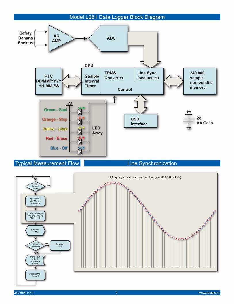
Model L261 Data Logger Block Diagram
330-668-1444 2 www.dataq.com
Typical Measurement Flow Line Synchronization
64 equally-spaced samples per line cycle (50/60 Hz ±2 Hz)
NoSampleInterval
Timeout?
Synchronizewith AC LineFrequency
Acquire 64 Samplesover one 50/60 Hz
AC line cycle
CalculateTRMS
AlarmCondition?
Yes Set AlarmState
Store TRMSValue to
Non-volatileMemory
Reset SampleInterval
SampleIntervalTimer
TRMSConverter
Line Sync(see insert)
Control
CPU
RTCDD/MM/YYYY
HH:MM:SS
USBInterface
240,000samplenon-volatilememory
2xAA Cells
ADCACAMP
+V
LEDArray
Green - Start
Orange - Stop
Yellow - Clear
Red - Erase
Blue - Off
+V
SafetyBananaSockets
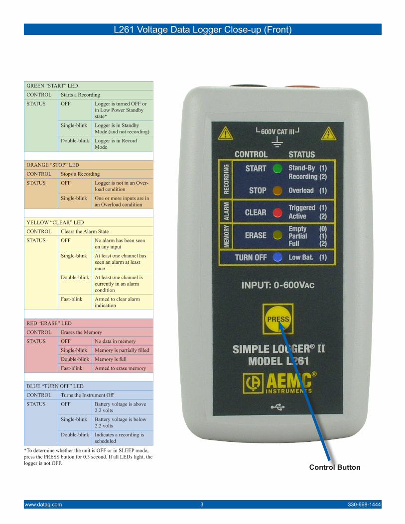
L261 Voltage Data Logger Close-up (Front)
www.dataq.com 3 330-668-1444
Control Button
GREEN “START” LED
CONTROL Starts a Recording
STATUS OFF Logger is turned OFF or in Low Power Standby state*
Single-blink Logger is in Standby Mode (and not recording)
Double-blink Logger is in Record Mode
ORANGE “STOP” LED
CONTROL Stops a Recording
STATUS OFF Logger is not in an Over-load condition
Single-blink One or more inputs are in an Overload condition
YELLOW “CLEAR” LED
CONTROL Clears the Alarm State
STATUS OFF No alarm has been seen on any input
Single-blink At least one channel has seen an alarm at least once
Double-blink At least one channel is currently in an alarm condition
Fast-blink Armed to clear alarm indication
RED “ERASE” LED
CONTROL Erases the Memory
STATUS OFF No data in memory
Single-blink Memory is partially filled
Double-blink Memory is full
Fast-blink Armed to erase memory
BLUE “TURN OFF” LED
CONTROL Turns the Instrument Off
STATUS OFF Battery voltage is above 2.2 volts
Single-blink Battery voltage is below 2.2 volts
Double-blink Indicates a recording is scheduled
*To determine whether the unit is OFF or in SLEEP mode, press the PRESS button for 0.5 second. If all LEDs light, the logger is not OFF.
330-668-1444 4 www.dataq.com
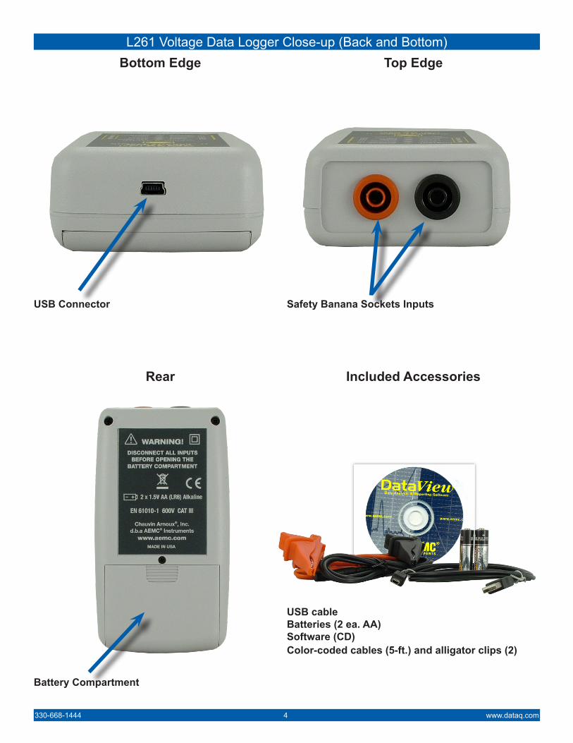
L261 Voltage Data Logger Close-up (Back and Bottom)
USB cableBatteries (2 ea. AA)Software (CD)Color-coded cables (5-ft.) and alligator clips (2)
Bottom Edge
USB Connector
Rear
Battery Compartment
Top Edge
Safety Banana Sockets Inputs
Included Accessories
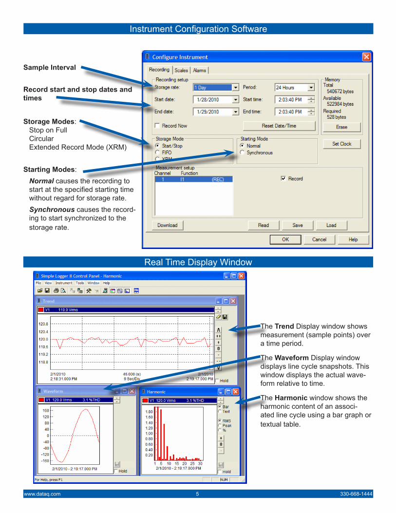
Instrument Configuration Software
www.dataq.com 5 330-668-1444
Real Time Display Window
Sample Interval
Record start and stop dates and times
Storage Modes:Stop on FullCircularExtended Record Mode (XRM)
Starting Modes:Normal causes the recording to start at the specified starting time without regard for storage rate.Synchronous causes the record-ing to start synchronized to the storage rate.
The Trend Display window shows measurement (sample points) over a time period.
The Waveform Display window displays line cycle snapshots. This window displays the actual wave-form relative to time.
The Harmonic window shows the harmonic content of an associ-ated line cycle using a bar graph or textual table.
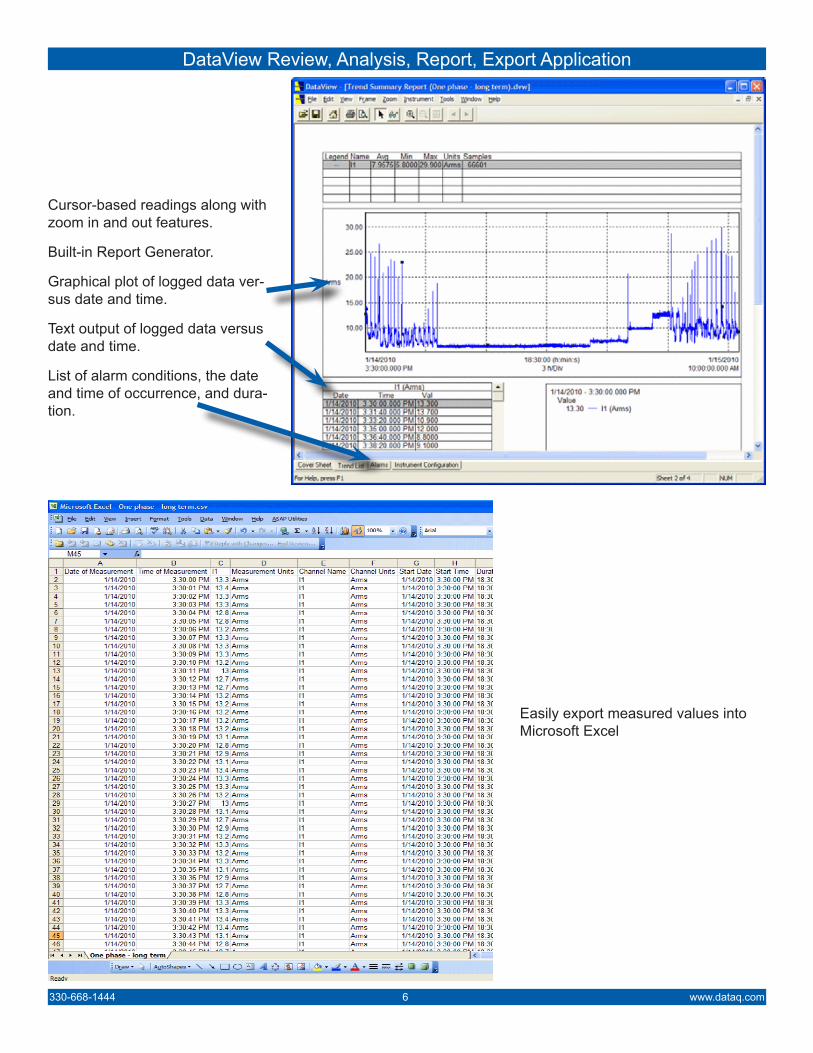
DataView Review, Analysis, Report, Export Application
330-668-1444 6 www.dataq.com
Cursor-based readings along with zoom in and out features.
Built-in Report Generator.
Graphical plot of logged data ver-sus date and time.
Text output of logged data versus date and time.
List of alarm conditions, the date and time of occurrence, and dura-tion.
Easily export measured values into Microsoft Excel
241 Springside DriveAkron, Ohio 44333
Phone: 330-668-1444Fax: 330-666-5434
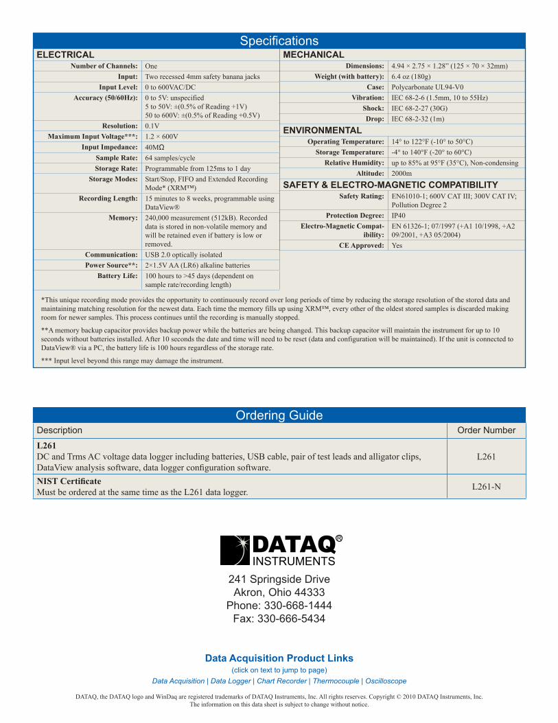
Specifications
Description Order Number
L261DC and Trms AC voltage data logger including batteries, USB cable, pair of test leads and alligator clips, DataView analysis software, data logger configuration software.
L261
NIST CertificateMust be ordered at the same time as the L261 data logger. L261-N
Ordering Guide
Data Acquisition Product Links(click on text to jump to page)
Data Acquisition | Data Logger | Chart Recorder | Thermocouple | Oscilloscope
DATAQ, the DATAQ logo and WinDaq are registered trademarks of DATAQ Instruments, Inc. All rights reserves. Copyright © 2010 DATAQ Instruments, Inc.The information on this data sheet is subject to change without notice.
ELECTRICALNumber of Channels: One
Input: Two recessed 4mm safety banana jacksInput Level: 0 to 600VAC/DC
Accuracy (50/60Hz): 0 to 5V: unspecified5 to 50V: ±(0.5% of Reading +1V)50 to 600V: ±(0.5% of Reading +0.5V)
Resolution: 0.1VMaximum Input Voltage***: 1.2 × 600V
Input Impedance: 40MΩSample Rate: 64 samples/cycleStorage Rate: Programmable from 125ms to 1 day
Storage Modes: Start/Stop, FIFO and Extended Recording Mode* (XRM™)
Recording Length: 15 minutes to 8 weeks, programmable using DataView®
Memory: 240,000 measurement (512kB). Recorded data is stored in non-volatile memory and will be retained even if battery is low or removed.
Communication: USB 2.0 optically isolatedPower Source**: 2×1.5V AA (LR6) alkaline batteries
Battery Life: 100 hours to >45 days (dependent on sample rate/recording length)
MECHANICALDimensions: 4.94 × 2.75 × 1.28” (125 × 70 × 32mm)
Weight (with battery): 6.4 oz (180g)Case: Polycarbonate UL94-V0
Vibration: IEC 68-2-6 (1.5mm, 10 to 55Hz)Shock: IEC 68-2-27 (30G)Drop: IEC 68-2-32 (1m)
ENVIRONMENTALOperating Temperature: 14° to 122°F (-10° to 50°C)
Storage Temperature: -4° to 140°F (-20° to 60°C)Relative Humidity: up to 85% at 95°F (35°C), Non-condensing
Altitude: 2000m
SAFETY & ELECTRO-MAGNETIC COMPATIBILITYSafety Rating: EN61010-1; 600V CAT III; 300V CAT IV;
Pollution Degree 2Protection Degree: IP40
Electro-Magnetic Compat-ibility:
EN 61326-1; 07/1997 (+A1 10/1998, +A2 09/2001, +A3 05/2004)
CE Approved: Yes
*This unique recording mode provides the opportunity to continuously record over long periods of time by reducing the storage resolution of the stored data and maintaining matching resolution for the newest data. Each time the memory fills up using XRM™, every other of the oldest stored samples is discarded making room for newer samples. This process continues until the recording is manually stopped.
**A memory backup capacitor provides backup power while the batteries are being changed. This backup capacitor will maintain the instrument for up to 10 seconds without batteries installed. After 10 seconds the date and time will need to be reset (data and configuration will be maintained). If the unit is connected to DataView® via a PC, the battery life is 100 hours regardless of the storage rate.
*** Input level beyond this range may damage the instrument.