dc Power Supply Options for PIC Projects - Suny...
14
Laboratory 15 Self-designed device. 1 Laboratory 15 Practical Advice for Microcontroller-based Design Projects (modified from lab text by Alciatore) The project for the course is described in detail on the course website. A rich source of information about other projects is available here: www.engr.colostate.edu/~dga/mech307/project.html The purpose for this "laboratory" is to summarize many useful practical resources, considerations, and suggestions that might be helpful to you in designing and implementing your project. Please read this material and apply the suggestions in your design. dc Power Supply Options for PIC Projects There are a number of ways to provide the dc power required by the PIC and any ancillary digital integrated circuits. Actuators may also be powered by the same dc supply if their drive voltage match that of the digital circuitry, and if the current demands do not exceed the supply's capacity. We begin by assuming that TTL digital ICs are used in the project, requiring a closely regulated 5 V dc source. If CMOS is used exclusively, there are fewer restrictions on the regulation of the dc voltage. Figure 15.1 shows various low cost options for powering systems requiring a 5V supply. The options include: 1. a 6 V, 9 V, or 12 V wall transformer with a 5 V regulator 2. a potted power supply with ac input and 5 V regulated output 3. four AA batteries (6 V) in series with a 5 V regulator 4. a 9 V battery with a 5 V regulator 5. a rechargeable battery (or batteries in series) with a 5 V regulator 6. a full featured instrumentation power supply Other alternatives for powering projects include a computer power supply, or large batteries (e.g., car or motorcycle lead-acid batteries), especially if you have high current demands.
Transcript of dc Power Supply Options for PIC Projects - Suny...

Laboratory 15 Self-designed device.
1
Laboratory 15
Practical Advice for Microcontroller-based Design Projects (modified from lab text
by Alciatore)
The project for the course is described in detail on the course website. A rich source of information
about other projects is available here:
www.engr.colostate.edu/~dga/mech307/project.html
The purpose for this "laboratory" is to summarize many useful practical resources, considerations, and
suggestions that might be helpful to you in designing and implementing your project. Please read this material
and apply the suggestions in your design.
dc Power Supply Options for PIC Projects There are a number of ways to provide the dc power required by the PIC and any ancillary digital integrated
circuits. Actuators may also be powered by the same dc supply if their drive voltage match that of the
digital circuitry, and if the current demands do not exceed the supply's capacity. We begin by assuming that TTL
digital ICs are used in the project, requiring a closely regulated 5 V dc source. If CMOS is used exclusively, there are
fewer restrictions on the regulation of the dc voltage.
Figure 15.1 shows various low cost options for powering systems requiring a 5V supply. The options
include:
1. a 6 V, 9 V, or 12 V wall transformer with a 5 V regulator
2. a potted power supply with ac input and 5 V regulated output
3. four AA batteries (6 V) in series with a 5 V regulator
4. a 9 V battery with a 5 V regulator
5. a rechargeable battery (or batteries in series) with a 5 V regulator
6. a full featured instrumentation power supply
Other alternatives for powering projects include a computer power supply, or large batteries (e.g., car or
motorcycle lead-acid batteries), especially if you have high current demands.

Laboratory 15 Self-designed device.
2
Figure 15.1 Low cost power supply options.
A wall transformer (6 V, 9 V, or 12 V) will provide current at its rating, and must be used with a 5 V regulator to control the level of the output voltage. Be sure that the current rating of the wall transformer exceeds the maximum current your circuit and actuators will draw. A potted power supply also has ac inputs and may provide one or more regulated dc outputs at its rated current. No voltage regulator is required if a 5 V output is provided. Four AA batteries may be connected in series with the 6 V output regulated down to 5 V with a voltage regulator. A 9 V battery must also be connected to a 5 V regulator. The battery options provide portability for your design but may not be able to supply enough current. Section 15.2 presents more information on different types of batteries and their characteristics. Generally, actuators such as motors and solenoids as well as LED's can draw substantial current, and batteries should be tested before assuming that they will provide sufficient current. Digital circuitry, on the other hand, usually draws very little current.
Figure 15.2 shows an example of a full-featured instrumentation power supply. This particular model (HP
6235A) is a triple-output power supply, with 3 adjustable voltage outputs, each independently current
rated. A full featured instrumentation power supply provides the easiest solution, but is expensive,
heavy, and generally is not portable.

Laboratory 15 Self-designed device.
3
Figure 15.2 An example of a full-featured instrumental power supply.
Except for the 5 V potted supply and the adjustable instrumentation power supply, voltage regulators are
required to convert the output voltage down to the 5 V level. If your system is entirely CMOS, the
regulation of the dc voltage is not required. Figure 15.3 illustrates a standard 7805 5 V voltage regulator
and shows how it is properly connected to your unregulated power supply output and your system.
There must be a common ground from the power supply to your system. The mounting hole on the heat
sink allows you to easily connect to the common ground.
Figure 14.3 7805 Voltage regulator connections.
Laboratory 15 Self-designed device.
4
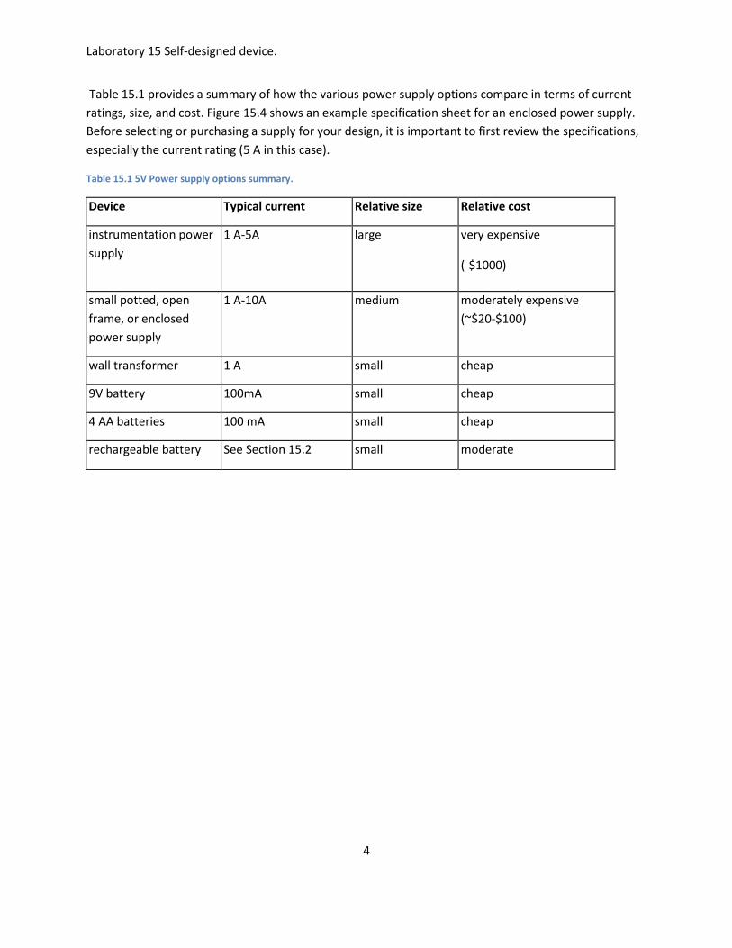
Table 15.1 provides a summary of how the various power supply options compare in terms of current
ratings, size, and cost. Figure 15.4 shows an example specification sheet for an enclosed power supply.
Before selecting or purchasing a supply for your design, it is important to first review the specifications,
especially the current rating (5 A in this case).
Table 15.1 5V Power supply options summary.
Device Typical current Relative size Relative cost
instrumentation power
supply
1 A-5A large very expensive
(-$1000)
but many features small potted, open
frame, or enclosed
power supply
1 A-10A medium moderately expensive
(~$20-$100)
wall transformer 1 A small cheap
9V battery 100mA small cheap
4 AA batteries 100 mA small cheap
rechargeable battery See Section 15.2 small moderate

Laboratory 15 Self-designed device.
5
Figure 15.4 Specifications for an example closed frame power supply from Jameco.
Laboratory 15 Self-designed device.
6
Battery Characteristics Many mechatronic designs will require dc voltage sources of some sort, usually tightly regulated, and
often with high current capacities if actuators such as dc motors or solenoids are used. Here we present
some of the important terms, considerations, and specifications in the proper selection of a battery as a
power source.
The most important specification for a battery (besides its rated voltage) is the amp-hour capacity. It is
defined as the current a battery can provide for one hour before it reaches its end-of-life point. The
current that a battery can deliver is limited by its equivalent series resistance, which is the internal
resistance that is in series with the "ideal voltage source" that is inside the battery. Batteries are
composed of cells, the electro-chemical device that supplies the voltage and current. Cells may be
combined in series or parallel within a battery for larger current and voltage capacities. The voltage of a
cell will differ among the types of batteries due to their chemistry.
Primary cells
Primanry cells are not rechargeable and are meant for one-time-use. Devices that are used infrequently
or that require very low drain currents are good candidates for primary cells.
Secondary cells
Secondary cells are rechargeable, and their effectiveness may be replenished many times. Devices that
require daily use with higher drain currents are good candidates for secondary cells.
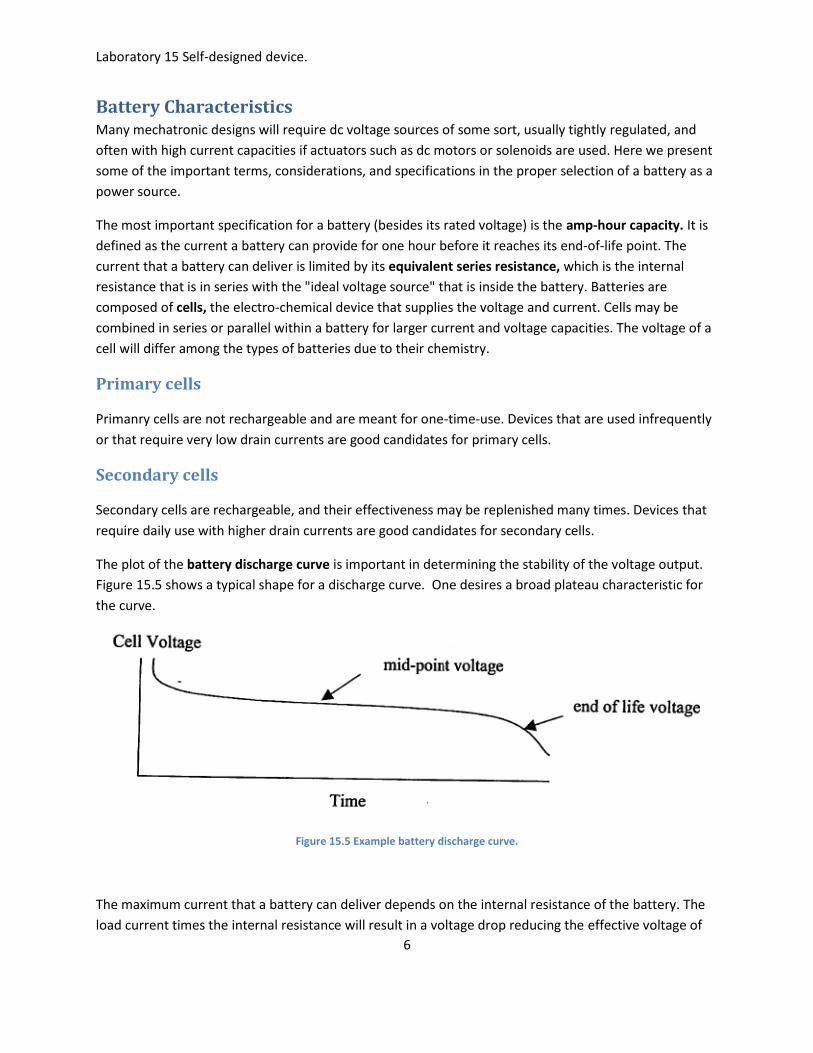
The plot of the battery discharge curve is important in determining the stability of the voltage output.
Figure 15.5 shows a typical shape for a discharge curve. One desires a broad plateau characteristic for
the curve.
Figure 15.5 Example battery discharge curve.
The maximum current that a battery can deliver depends on the internal resistance of the battery. The
load current times the internal resistance will result in a voltage drop reducing the effective voltage of

Laboratory 15 Self-designed device.
7
the battery. Furthermore, there will be power dissipated by the internal resistance that, at high
currents, may result in considerable heat production. The salient factors a designer must consider in the
selection of a power source for a mechatronic design are:
voltage required by the load
current required by the load
duty cycle of the system
cost
size and weight (specific energy)
need for rechargeability
As shown in Table 15.2, the chemistry of the cell will determine its open circuit voltage. High drain rate devices are good candidates for lead-acid and NiCd batteries. If a device is in storage most of the time, alkaline batteries are appropriate. Since batteries may be the heaviest component of a mechatronic design, the very light Li-ion and lithium-polymer chemistries may be good candidates. Lithium chemistries provide the highest energy per unit weight (specific energy) and per volume (energy density) of all types of batteries.
Rechargeable batteries will function well even after hundreds of cycles. Rechargeable batteries are significantly more expensive than primary cell batteries. Ni-MH batteries should be deep discharged several times when put into service for best performance. Ni-Cd batteries can suffer from an effect called "memory" where the battery capacity can diminish over time. It is caused by shallow charge cycles where the battery is only partially discharged and then fully charged repeatedly. You should give the battery a deep discharge from time to time for best performance.

Laboratory 15 Self-designed device.
8
Table 15.2 Characteristics for various types of batteries.
Type Voltage
(open
circuit)
circuit)
Type Typical Ah
Capacity
R internal
(Q)
9V (heavy duty) 9V primary 0.30 @1 mA
0.15@10mA
35
9V alkaline 9 V primary 0.60 @ 25 mA 2
9V lithium 9V primary 1.0 @ 25 mA
0.95 @ 80 mA
18
alkaline D 1.5 V primary 17.1 @25mA 0.1
alkaline C 1.5 V primary 7.9 @ 25 mA 0.2
alkaline AA 1.5 V primary 2.7 @ 25 mA 0.4
alkaline AAA 1.5 V primary 1.2@25mA 0.6
BR-C PCMF-Li 3 V primary 5.0 @ 5 mA
CR-V3 Mn-Li 3 V primary 3.0 @ 100 mA
Ni-Cd D 1.3 V secondary 4.0 @ 800 mA
3.5 @4 A
0.009
Ni-Cd 9V 8.1 V secondary 0.1 @10mA 0.84
Lead-acid D 2.0 V secondary 2.5 @ 25 mA
2.0 @ 1 A
0.006
Ni-MH AAA 1.2V secondary 0.55 @ 200 mA
Ni-MH AA 1.2 V secondary 1.3 @ 200 mA
Ni-MH C 1.2 V secondary 3.5 @ 200 mA
Ni-MH D 1.2 V secondary 7.0 @ 200 mA
Ni-MH 9V 8.4 V secondary 0.13 @ 200 mA
ML2430 Mn-Li 3 V secondary 0.12 @ 300 mA
Lithium Ion 3.7 V secondary 0.76 @ 200 mA

Laboratory 15 Self-designed device.
9
Relays and Power Transistors Actuators often require large currents at voltages different from the control circuit. Control signals are
interfaced to actuator and other large current devices using relays or power transistors.
When a circuit must be completely on or off with minimal on-state voltage drop, the electromagnetic
(EMR) is the only suitable choice. Solid state relays (SSRs) are the most durable and reliable but are
never completely on or off and can have substantial on-state voltage drops with associated heat
generation. Relays can switch dc or ac power.
Power transistors switch currents extremely fast and with less electromagnetic interference than EMRs.
Power bipolar junction transistors (BJTs) and field effect transistors (FETs) can be used to switch dc
power. FETs are easier to implement in a design because they do not require voltage biasing at the
input, ac power cannot be switched with BJTs or FETs. Silicon controlled rectifiers (SCRs) and TRIACS are
solid state devices that can switch ac power. Voltage and current capacities are important criteria when
selecting any of these devices.
Here is a summary of the pros and cons of relays and transistors:
Transistors:
can switch much faster than relays.
produce less electromagnetic interference.
last longer than most relays.
can be used as current amplifiers where the output current varies with the input voltage.
Relays:
provide electrical isolation between the signal circuit and power circuit so the control circuitry is
unaffected by the power circuit.
can switch larger currents in general.
do not require voltage biasing at the input.
have minimal on-state resistance and maximum off-state resistance.
can switch dc or ac power.

Laboratory 15 Self-designed device.
10
Soldering Once a prototype circuit has been tested on a breadboard, a permanent prototype can be created by
soldering components and connections using a protoboard (also called a perf board, perforated board,
or vector board). These boards are manufactured with a regular square matrix of holes spaced 0.1 in
apart as with the insertion points in a breadboard. Unlike with the breadboard, there are no pre-wired
connections between the holes. All connections must be completed with external wire and solder joints.
The result is a prototype that is more robust, and that can be used in a prototype mechatronic system.
You should consider this method for your class project.
For multiple versions of a prototype or production version of a circuit, a printed circuit
board (PCB) is manufactured. Here, components are inserted and soldered to perforations in the
board and all connections between the components are "printed" with a conducting medium. We do
not support facilities to produce PCBs, but they are common in manufacturing environments.
Solder is a metallic alloy of tin, lead and other elements that has a low melting point (approximately
375°F). The solder usually is supplied in wire form often with a flux core, that facilitates melting and
wetting of metallic surfaces. The solder is applied to wire and electronic components using a soldering
iron consisting of a heated tip and support handle (see Figure 15.6). Sometimes you can also select the
temperature of the tip using a rheostat. When using the soldering iron, be sure the tip is securely
installed. Then after heating be sure the tip is clean and shiny. If not briefly wipe it on a wet sponge.
Figure 15.6 Soldering iron.
Steps in creating a good solder connection:
1. Before soldering, assemble your materials: a hot soldering iron, solder, components, wire,
protoboard or perforated board, wet sponge and magnifying glass.
2. Clean any surfaces that are to be joined. You may use fine emery paper or a metal brush to remove
oxide layers and dirt so that the solder may easily wet the surface. Rosin core (flux) solder will
enhance the wetting process.
3. Make a mechanical contact between elements to be joined, either by bending or twisting, and ensure
that they are secure so that they will not move when you apply the iron. Figure 15.7 illustrates two
wires twisted together and a component inserted in a protoboard in preparation for soldering.

Laboratory 15 Self-designed device.
11
4. Heating the elements to be joined is necessary so that "the solder properly wets both elements
and a strong bond results. When using electronic components, practice in heating is necessary
so that the process is swift enough not to thermally damage the silicon device. Soldering irons with
sharper tips are convenient for joining small electronic components, since they can deliver the heat
very locally.
Figure 15.7 Preparing a soldered joint.
5. When the work has been heated momentarily, apply the solder to the work (not the soldering iron) and
it should flow fluidly over the surfaces. Feed enough solder to provide a robust but not blobby joint.
(If the solder balls up on the iron the work is not hot enough.) Smoothly remove the iron and
allow the joint to solidify momentarily. You should see a slight change in surface texture of the
solder when it solidifies. If the joint is ragged or dull you may have a cold joint, one where the solder has
not properly wetted the elements. Such a joint will create problems in conductivity and must be
repaired by resoldering. Figure 15.8 illustrates a successful solder joint where the solder has wet both
surfaces, in this case a component lead in a metal hole perforated board.
Figure 15.8 A successful solder joint.
6. If flux solvent is available, wipe the joint clean.
7. Inspect your work with a magnifying glass to see that the joint has been properly made.

Laboratory 15 Self-designed device.
12
Often you may have a small component or integrated circuit (IC) that you do not want to heat excessively.
To avoid excessive heat with a small component, you may use a heat sink. A heat sink is a piece of metal
like an alligator clip connected to the wire between the component and the connection to help absorb
some of the heat that would be conducted to the component. However if the heat sink is too close to the
connection it will be hard to heat the wires. When using an IC, a socket can be soldered into the protoboard
first, and then the IC inserted, thereby avoiding any thermal stress on the IC.
When using hook-up wire, be sure to use solid wire on a protoboard since it will be easy to manipulate and
join. Wire must be stripped of its insulating cover before soldering. When using hook-up wire in a circuit,
tinning the wire first (covering the end with a thin layer of solder) facilitates the joining process.
Often you may make mistakes in attaching components and need to remove one or more soldered
joints. A solder sucker makes this a lot easier. To use a solder sucker (see Figure 15.9), cock it first, heat
the joint with the soldering iron, then trigger the solder sucker to remove the molten solder. Then the
components can easily be removed since very little solder will be left to hold them.
Figure 15.9 Removing a solder joint.
Laboratory 15 Self-designed device.
13
Other Practical Considerations For basic prototype circuit assembly and troubleshooting advice, see the trouble shooting and debugging
sections of labs 10 (digital circuits in general) and 13 (PIC microcontrollers in particular).
Here are some other practical suggestions for microcontroller-based designs:
General Electrical Design Suggestions When ordering ICs, make sure you specify DIP (dual in-line packages) and not surface mount
packages (e.g., SOP). DIP chips are well suited to use in breadboards and protoboards. Surface
mount ICs require printed circuit boards (PCBs) and special soldering equipment.
Make sure your power supply can provide adequate current for the entire design. If necessary,
use separate power supplies for your signal and power circuits.
Use breadboards with caution and care because connections can be unreliable, and the base plate
adds capacitance to your circuits. Hard-wired and soldered protoboards or printed circuit boards
(PCBs) can be much more reliable. See previous section for advice on how to solder properly. Be
sure to use sockets for all ICs to prevent damage during soldering and to allow easy replacement
of the ICs. Also, if you have a working breadboard circuit, it is advisable to use duplicate
components (where possible) for the soldered board (i.e., don't cannibalize components from a
working prototype circuit in case something goes wrong or gets damaged when soldering your
board).
Use a storage capacitor (e.g., 100 F) across the main power and ground lines of a power supply
that does not have built in output capacitance (e.g., batteries, wall transformers, and regulated
voltages) to minimize voltage swings during output current spikes. Also, use bypass capacitors
(e.g., 0.1 F) across the power and grounds lines of all individual ICs to suppress any current and
voltage spikes.
Make sure all components and sources have a common ground unless using relays, wireless
interfaces, or opto-isolators, in which case you should keep the independent power supply
grounds separate.
Avoid grounding problems and electromagnetic interference (EMI). Section 2.10 in the
textbook presents various methods to reduce EMI, specifically using opto-isolators, single point
grounding, ground planes, coaxial or twisted pair cables, and bypass capacitors.
Don't leave IC pins floating (especially with CMOS devices). In other words, connect all used and
functional pins to signals or power or ground. As an example, do not assume that leaving a
microcontroller's reset pin disconnected will keep a microcontroller from resetting itself. You
should connect the reset pin to 5V for an active-low reset or ground for an active-high reset, and
not leave the pin floating where its state can be uncertain.
Be aware of possible switch bounce in your digital circuits and add debounce circuits or software
to eliminate the debounce.
Use flyback diodes on motors, solenoids, and other high inductance devices that are being
switched.

Laboratory 15 Self-designed device.
14
Use buffers, line drivers, and inverters where current demand is large for a digital output.
Use Schmitt -triggers on all noisy digital sensor outputs (e.g., a Hall-effect proximity sensor or photo-
interrupter).
Use a common-emitter configuration with transistors (i.e., put the load on the high side) to avoid
voltage biasing difficulties.
Be careful to identify and properly interface any open-collector or open-drain outputs on digital
ICs (e.g., pin RA4 on the PIC).
For reversible dc motors, use "off-the-shelf commercially available H-bridge drivers (e.g.,
National Semiconductor's LMD 18200) instead of building your own.
PIC-related Suggestions (see more in trouble shooting section of Lab 13) Follow the microcontroller design procedure in Section 7.9 of the textbook.
Modularize your software and independently develop and test each module (i.e., don't write the entire
program at once expecting it to work).
Use LEDs to indicate status and location within your program when it is running, and to indicate
input and output states.
Be aware of the different characteristics of the I/O pins on the PIC. Refer to Figures 7.15 and 7.16 in
the textbook to see how to properly interface to the different pins for different purposes.
Be aware that the PIC is totally occupied while running commands (e.g., the line after a command is
not reached or processed until the current command has terminated).
Refer to Design Example 7.1 in the textbook for ideas on how to interface to 7-segment digital displays
with a minimum number of pins.
When prototyping with a soldered protoboard or printed circuit board, use IC sockets to allow easy
installation and removal of the PICs without damaging pins. Also, always use a "chip puller" tool to
remove ICs (e.g., PICs) from breadboards or soldered IC sockets.