DC overvoltage protection - Siemens AG · The SICROWBAR DC overvoltage protection is a symmetric...
76
Edition Operating Instructions 02/2014 SICROWBAR DC DC overvoltage protection Answers for industry.
Transcript of DC overvoltage protection - Siemens AG · The SICROWBAR DC overvoltage protection is a symmetric...

Edition
Operating Instructions
02/2014
SICROWBAR DCDC overvoltage protection
Answers for industry.

DC overvoltage protection
___________________
___________________
___________________
___________________
___________________
___________________
___________________
___________________
___________________
___________________
___________________
___________________
___________________
___________________
___________________
SICROWBAR DC
DC overvoltage protection
Operating Instructions
A5E34279422A
Introduction 1
Safety information 2
Description 3
Preparations for use 4
Installation 5
Electrical connection 6
Commissioning 7
Operation 8
Maintenance 9
Spare parts 10
Disposal 11
Service and Support A
Technical specifications and drawings
B
Appendix C C
Additional documents D
Siemens AG Industry Sector Postfach 48 48 90026 NÜRNBERG GERMANY
Order number: A5E34279422A 05/2014 Subject to change
Copyright © Siemens AG 2014. All rights reserved
Legal information Warning notice system
This manual contains notices you have to observe in order to ensure your personal safety, as well as to prevent damage to property. The notices referring to your personal safety are highlighted in the manual by a safety alert symbol, notices referring only to property damage have no safety alert symbol. These notices shown below are graded according to the degree of danger.
DANGER indicates that death or severe personal injury will result if proper precautions are not taken.
WARNING indicates that death or severe personal injury may result if proper precautions are not taken.
CAUTION indicates that minor personal injury can result if proper precautions are not taken.
NOTICE indicates that property damage can result if proper precautions are not taken.
If more than one degree of danger is present, the warning notice representing the highest degree of danger will be used. A notice warning of injury to persons with a safety alert symbol may also include a warning relating to property damage.
Qualified Personnel The product/system described in this documentation may be operated only by personnel qualified for the specific task in accordance with the relevant documentation, in particular its warning notices and safety instructions. Qualified personnel are those who, based on their training and experience, are capable of identifying risks and avoiding potential hazards when working with these products/systems.
Proper use of Siemens products Note the following:
WARNING Siemens products may only be used for the applications described in the catalog and in the relevant technical documentation. If products and components from other manufacturers are used, these must be recommended or approved by Siemens. Proper transport, storage, installation, assembly, commissioning, operation and maintenance are required to ensure that the products operate safely and without any problems. The permissible ambient conditions must be complied with. The information in the relevant documentation must be observed.
Trademarks All names identified by ® are registered trademarks of Siemens AG. The remaining trademarks in this publication may be trademarks whose use by third parties for their own purposes could violate the rights of the owner.
Disclaimer of Liability We have reviewed the contents of this publication to ensure consistency with the hardware and software described. Since variance cannot be precluded entirely, we cannot guarantee full consistency. However, the information in this publication is reviewed regularly and any necessary corrections are included in subsequent editions.
DC overvoltage protection Operating Instructions, , A5E34279422A 5
Table of contents
1 Introduction ............................................................................................................................................. 7
2 Safety information ................................................................................................................................... 9
2.1 Safety information .......................................................................................................................... 9
2.2 ESD-sensitive components .......................................................................................................... 11
3 Description ............................................................................................................................................ 13
3.1 Overview ...................................................................................................................................... 14
3.2 Type spectrum ............................................................................................................................. 15 3.2.1 Device order numbers .................................................................................................................. 15 3.2.2 Type plate .................................................................................................................................... 17 3.2.3 Packaging label ............................................................................................................................ 17
3.3 Functions ...................................................................................................................................... 18 3.3.1 Monitoring functions ..................................................................................................................... 18 3.3.1.1 Voltage measurement for de-energization/discharge resistor ..................................................... 18 3.3.1.2 Wire break in supply line XEW1................................................................................................... 18 3.3.1.3 Overload at de-energization/discharge resistor ........................................................................... 19 3.3.1.4 Switching on and failure of the electronic power supply .............................................................. 19 3.3.2 Fast de-energization option ......................................................................................................... 20
3.4 Selecting the appropriate SICROWBAR and design notes (including options) ........................... 21 3.4.1 Selection according to operate voltage ........................................................................................ 21 3.4.1.1 Selection when using Siemens power converters (SINAMICS DCM, SIMOREG DC-
MASTER) ..................................................................................................................................... 21 3.4.1.2 Selection when using different power converters ........................................................................ 21 3.4.2 Selection according to maximum current ..................................................................................... 23 3.4.2.1 Without option G11 ...................................................................................................................... 23 3.4.2.2 With option G11 ........................................................................................................................... 23 3.4.2.3 Operation in a voltage DC link with a capacitor ........................................................................... 24
3.5 Modules ........................................................................................................................................ 24 3.5.1 Voltage measurement .................................................................................................................. 24 3.5.1.1 Switching thresholds and series resistors of the "current flow" monitoring function .................... 24 3.5.1.2 Threshold values for wire break ................................................................................................... 25 3.5.2 Fast de-energization option ......................................................................................................... 25
3.6 Applicable standards .................................................................................................................... 25
3.7 Abbreviations, terminology ........................................................................................................... 26
4 Preparations for use .............................................................................................................................. 27
4.1 Transport, unpacking ................................................................................................................... 27
4.2 Storage ......................................................................................................................................... 27
5 Installation ............................................................................................................................................ 29
6 Electrical connection ............................................................................................................................. 31
Table of contents
DC overvoltage protection 6 Operating Instructions, , A5E34279422A
6.1 Connection suggestions .............................................................................................................. 32
6.2 Arrangement of terminals ............................................................................................................ 33
6.3 Terminal description .................................................................................................................... 34 6.3.1 Terminals 3 and 4 ....................................................................................................................... 34 6.3.2 Two-tier terminal 30 to 47 ........................................................................................................... 35 6.3.3 Terminals 50 to 64 (relays 1 to 5) ............................................................................................... 36 6.3.4 Settings for switch S6 for linking the inverse current flow to wire break ..................................... 37 6.3.5 Settings for switches S1 to S5 for "current flow" pulse stretching .............................................. 38
6.4 Power connections and terminals ............................................................................................... 39 6.4.1 Power connections ...................................................................................................................... 39 6.4.2 PE terminal .................................................................................................................................. 40 6.4.3 Terminals..................................................................................................................................... 40 6.4.4 Connecting the signal lines ......................................................................................................... 42
7 Commissioning ..................................................................................................................................... 43
8 Operation .............................................................................................................................................. 45
9 Maintenance ......................................................................................................................................... 47
9.1 Replacing components ................................................................................................................ 48
10 Spare parts ........................................................................................................................................... 53
11 Disposal ................................................................................................................................................ 55
A Service and Support ............................................................................................................................. 59
A.1 Service ........................................................................................................................................ 59
A.2 Technical Support ....................................................................................................................... 59
A.3 Service calls ................................................................................................................................ 60
B Technical specifications and drawings ................................................................................................... 61
B.1 Technical data ............................................................................................................................. 61
B.2 Typical load current characteristic for the three device power stages ........................................ 65
B.3 Restart time (recovery time) ........................................................................................................ 65
B.4 Dimension drawings .................................................................................................................... 67
B.5 Circuit diagram ............................................................................................................................ 68
C Appendix C ........................................................................................................................................... 69
D Additional documents ............................................................................................................................ 71
D.1 De-energization/discharge resistor and thermostatic switch ...................................................... 71
D.2 External DC power supply ........................................................................................................... 74
DC overvoltage protection Operating Instructions, , A5E34279422A 7
Introduction 1
These Operating Instructions contain all information relating to:
Ordering, assembly, connection, commissioning, maintenance, functional description
and service.

Introduction
DC overvoltage protection 8 Operating Instructions, , A5E34279422A
DC overvoltage protection Operating Instructions, , A5E34279422A 9
Safety information 2 2.1 Safety information
Note
In the interests of clarity, these Operating Instructions do not contain full details of all information for all product types and cannot take into account every possible aspect of installation, operation, or maintenance.
If you require further information, or particular problems arise which these Operating Instructions do not cover in enough detail, please contact your local Siemens office.
We also draw your attention to the fact that the contents of these Operating Instructions are not part of and do not modify any prior or existing agreement, commitment, or legal relationship. Any obligations on the part of Siemens arise from the respective contract of sale, which also contains the solely valid warranty conditions in full. Any statements contained in these Operating Instructions neither expand nor restrict the scope of these contractual warranty conditions.
WARNING
Dangerous voltages
The unit is at a hazardous voltage. Failure to comply with these Operating Instructions can lead to death, serious physical injury, and material damage.
Only qualified personnel who are familiar with all the safety instructions provided in these Operating Instructions, as well as the assembly, operating, and maintenance instructions, should carry out work on this unit.
WARNING
Connections with electrical separation
There is electrical separation according to the requirements for protection against electric shock according to EN61800-5-1 at all customer connections with input/output voltages in the range up to 60 V DC (DVC A).
This is the reason that only components whose inputs/output voltages lie in this range and which also have electrical separation can be connected at these connections.
Safety information 2.1 Safety information
DC overvoltage protection 10 Operating Instructions, , A5E34279422A
WARNING
Installation and operation to be carried out by trained personnel only
When this unit is operated, it is inevitable that certain components will be subject to dangerous electrical voltage levels. Touching these components may lead to serious physical injury or even death. The following precautions must be taken in order to reduce the risk to life and limb: 1. Only qualified personnel who are familiar with this unit and the information supplied with
it should be charged with work on the unit involving installation, operation, troubleshooting and fault correction, or repair.
2. The unit must be installed in accordance with safety regulations (e.g. EN, DIN, or VDE) as well as all other applicable national or local regulations. Grounding, conductor dimensioning, and the relevant short-circuit protection work must be carried out correctly in order to ensure operational safety.
3. The unit must be operated with all covers supplied. The fixing screws for the front cover of the SICROWBAR must be tight. When required, additional covers should be provided in the control cabinet.
4. Before carrying out maintenance work, it must be ensured that the unit is disconnected from all power supplies, disabled, and grounded. Before they are shut down, both the converter unit and the excitation winding are subject to dangerous voltage levels; A hazardous voltage is present even if the converter device contactor is open.
5. If measurements need to be taken while the power supply is switched on, do not under any circumstances touch the electrical connection points. Remove all jewelry from wrists and fingers. Make sure that the measuring and test equipment is in good condition and is safe to operate.
6. When working on a unit that is switched on and on an insulated surface, make sure that no grounding has been put in place.
7. Follow these Operating Instructions faithfully and observe all information concerning hazards, warnings, or areas where caution is required.
8. This list is not exhaustive and as such cannot outline all the measures required in order to operate the unit safely. Should you require further information or encounter specific problems which have not been handled in enough detail for the purposes of the buyer, please contact your local Siemens office.
Safety information 2.2 ESD-sensitive components
DC overvoltage protection Operating Instructions, , A5E34279422A 11
2.2 ESD-sensitive components
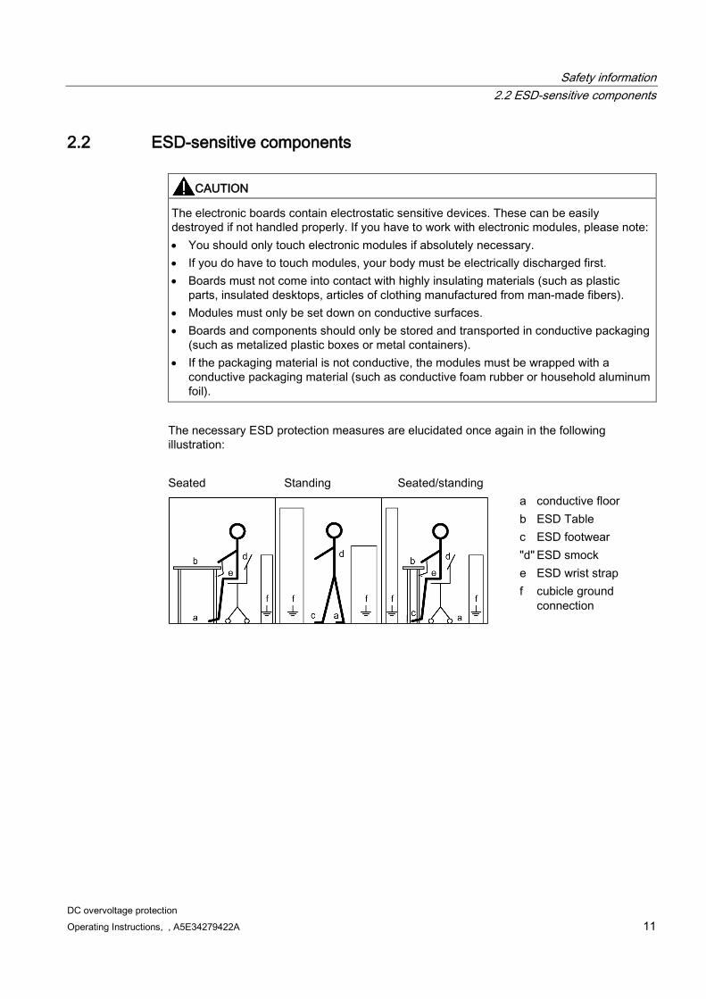
CAUTION
The electronic boards contain electrostatic sensitive devices. These can be easily destroyed if not handled properly. If you have to work with electronic modules, please note: • You should only touch electronic modules if absolutely necessary. • If you do have to touch modules, your body must be electrically discharged first. • Boards must not come into contact with highly insulating materials (such as plastic
parts, insulated desktops, articles of clothing manufactured from man-made fibers). • Modules must only be set down on conductive surfaces. • Boards and components should only be stored and transported in conductive packaging
(such as metalized plastic boxes or metal containers). • If the packaging material is not conductive, the modules must be wrapped with a
conductive packaging material (such as conductive foam rubber or household aluminum foil).
The necessary ESD protection measures are elucidated once again in the following illustration:
Seated Standing Seated/standing
a conductive floor b ESD Table c ESD footwear "d" ESD smock e ESD wrist strap f cubicle ground
connection

Safety information 2.2 ESD-sensitive components
DC overvoltage protection 12 Operating Instructions, , A5E34279422A
DC overvoltage protection Operating Instructions, , A5E34279422A 13
Description 3
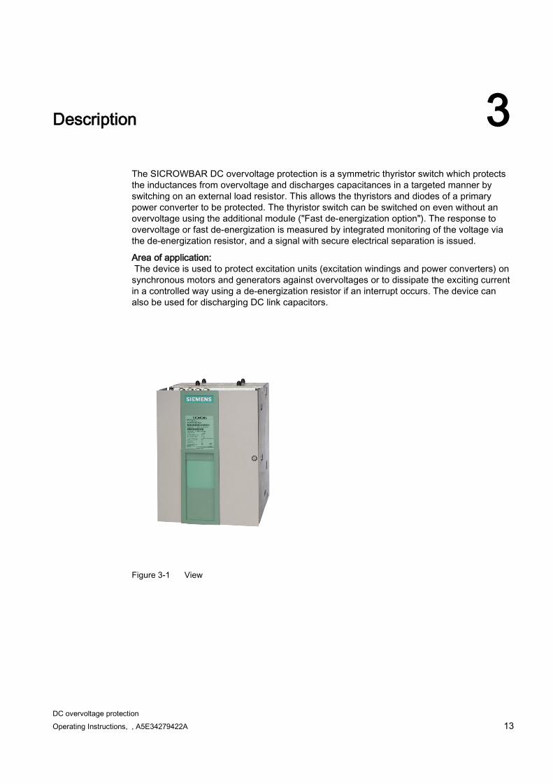
The SICROWBAR DC overvoltage protection is a symmetric thyristor switch which protects the inductances from overvoltage and discharges capacitances in a targeted manner by switching on an external load resistor. This allows the thyristors and diodes of a primary power converter to be protected. The thyristor switch can be switched on even without an overvoltage using the additional module ("Fast de-energization option"). The response to overvoltage or fast de-energization is measured by integrated monitoring of the voltage via the de-energization resistor, and a signal with secure electrical separation is issued.
Area of application: The device is used to protect excitation units (excitation windings and power converters) on synchronous motors and generators against overvoltages or to dissipate the exciting current in a controlled way using a de-energization resistor if an interrupt occurs. The device can also be used for discharging DC link capacitors.
Figure 3-1 View

Description 3.1 Overview
DC overvoltage protection 14 Operating Instructions, , A5E34279422A
3.1 Overview
Figure 3-2 Schematic circuit diagram
Method of operation SICROWBAR DC overvoltage protection monitors the voltage at terminals C and D of the power converter or the excitation winding. Once the operate voltage has been reached, the de-energization resistor is connected in parallel to the excitation winding by a thyristor. This means that the energy in the excitation winding can be safely dissipated in the excitation unit even if an interrupt occurs.
Repeating the switching operation is only permitted after a sufficient cooling time has elapsed. See Chapter Restart time (recovery time) (Page 65). The current flow in the thyristor is measured via the voltage at the de-energization resistor and is signaled with secure electrical separation. The recommended thermostatic switch measures any overheating of the de-energization resistor. The additional fast de-energization option makes it possible to trigger ignition even if there is no overvoltage.
Design The components of the device are:
Power connections (copper bars) C, D
Two thyristors V1, V2 connected antiparallel
Firing module which ignites the thyristor in the relevant blocking direction at the operate voltage (800 V, 1,200 V, 1,600 V, 1,900 V, 2,200 V, 2,600 V, and 3,000 V).
Description 3.2 Type spectrum
DC overvoltage protection Operating Instructions, , A5E34279422A 15
Voltage measurement for de-energization/discharge resistor and thermostatic switch
Terminal XEW1 (connection to the voltage measurement brought out via series resistor R12)
Series resistors R11 and R12: 2 × 15 kΩ (up to 1,200-V devices), 2 × 30 kΩ (from 1,600-V devices)
OPTION G11: The fast de-energization module makes it possible to ignite the thyristors via three relays which can be selected independently.
For the mechanical design, see Chapter Dimension drawings (Page 67).
3.2 Type spectrum
3.2.1 Device order numbers
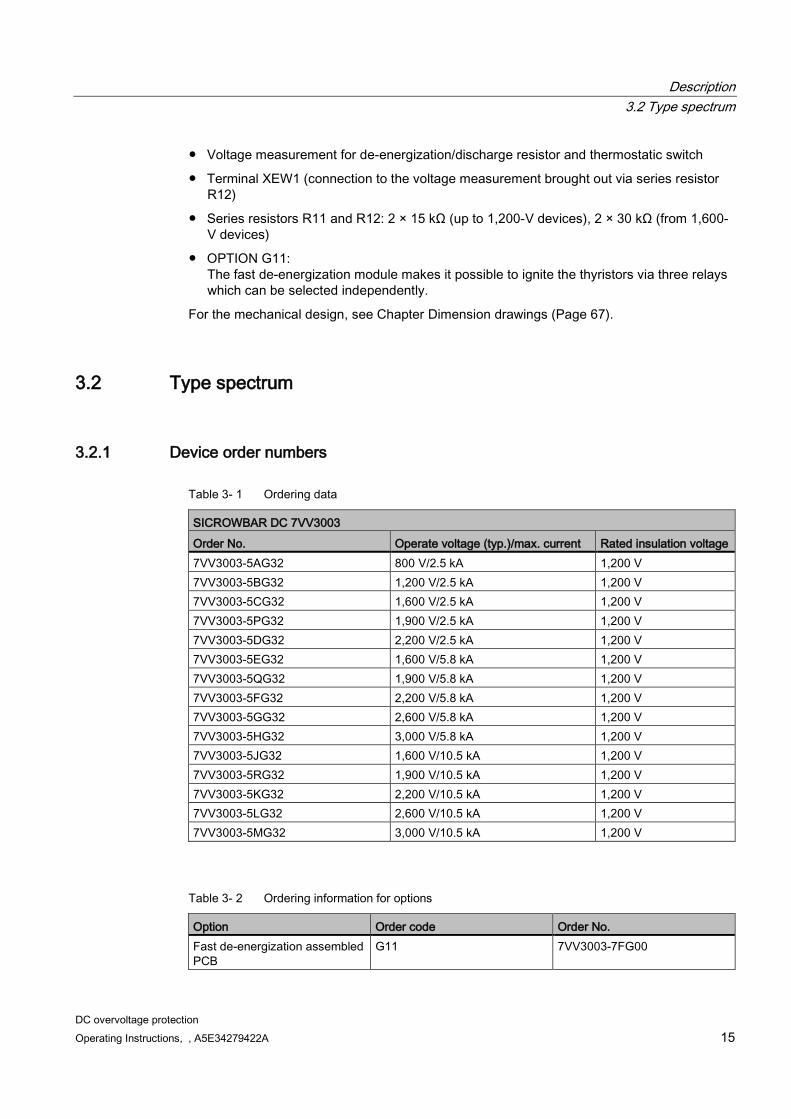
Table 3- 1 Ordering data
SICROWBAR DC 7VV3003 Order No. Operate voltage (typ.)/max. current Rated insulation voltage 7VV3003-5AG32 800 V/2.5 kA 1,200 V 7VV3003-5BG32 1,200 V/2.5 kA 1,200 V 7VV3003-5CG32 1,600 V/2.5 kA 1,200 V 7VV3003-5PG32 1,900 V/2.5 kA 1,200 V 7VV3003-5DG32 2,200 V/2.5 kA 1,200 V 7VV3003-5EG32 1,600 V/5.8 kA 1,200 V 7VV3003-5QG32 1,900 V/5.8 kA 1,200 V 7VV3003-5FG32 2,200 V/5.8 kA 1,200 V 7VV3003-5GG32 2,600 V/5.8 kA 1,200 V 7VV3003-5HG32 3,000 V/5.8 kA 1,200 V 7VV3003-5JG32 1,600 V/10.5 kA 1,200 V 7VV3003-5RG32 1,900 V/10.5 kA 1,200 V 7VV3003-5KG32 2,200 V/10.5 kA 1,200 V 7VV3003-5LG32 2,600 V/10.5 kA 1,200 V 7VV3003-5MG32 3,000 V/10.5 kA 1,200 V
Table 3- 2 Ordering information for options
Option Order code Order No. Fast de-energization assembled PCB
G11 7VV3003-7FG00

Description 3.2 Type spectrum
DC overvoltage protection 16 Operating Instructions, , A5E34279422A
Order number without option 7VV3003-5..32
Order number with option 7VV3003-5..32-Z G11
Note:
See also Selecting the appropriate SICROWBAR and design notes (including options) (Page 21).
Scope of delivery Device
DVD (Operating Instructions, replacement instructions, safety instructions)
Not part of the scope of delivery: External de-energization/discharge resistor
External thermostatic switch
Mounting bracket for external thermostatic switch
Junction terminal for external thermostatic switch
Rear panel fixing screws
Electric power cable fixing screws
Electric power cable
Description 3.2 Type spectrum
DC overvoltage protection Operating Instructions, , A5E34279422A 17
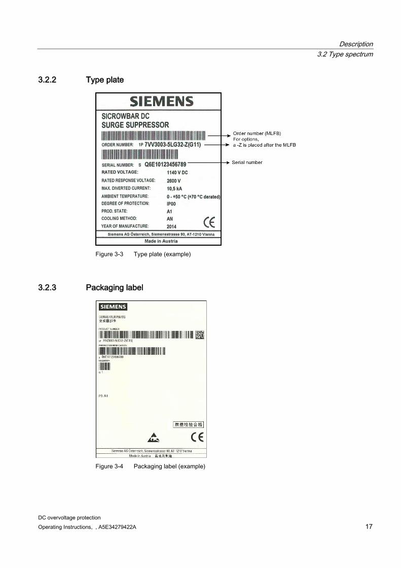
3.2.2 Type plate
Figure 3-3 Type plate (example)
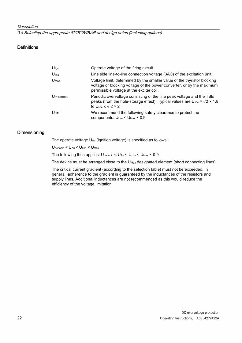
3.2.3 Packaging label
Figure 3-4 Packaging label (example)

Description 3.3 Functions
DC overvoltage protection 18 Operating Instructions, , A5E34279422A
3.3 Functions
3.3.1 Monitoring functions
3.3.1.1 Voltage measurement for de-energization/discharge resistor The voltage measurement module is connected to busbar C via series resistors (R11, R12) and to the external de-energization/discharge resistor via terminal XEM1.
The following signal states are generated by querying the voltage between busbar C and terminal XEW1:
Current flow (terminal 35, 42) LOW= voltage below the threshold (no current flow) HIGH= voltage is above the threshold (current flow) See Two-tier terminal 30 to 47 (Page 35).
Inverse current flow (terminal 34, 40) Terminal 35, 42 inverted
Relays K1 to K3: drop out when current is flowing For the position of the contacts, see the relay contacts table
These signals are used to deactivate the power converter after it responds or to set the current to zero.
For details on the switching thresholds, see Table 3-5 Switching thresholds and series resistors of the "current flow" monitoring function (Page 24).
When the "current flow" signal stops being displayed, this does not mean that the electric circuit is actually current free. Restarting with capacitor DC links is only permitted once current=0. It is possible to delay the disappearance of the "current flow" signal using adjustable pulse stretching to bridge the wait time.
See Chapter Settings for switches S1 to S5 for "current flow" pulse stretching (Page 38).
3.3.1.2 Wire break in supply line XEW1 The interrupt (wire break) in external line XEW1 to the de-energization/discharge resistor is reported in 3 ways.
Open-circuit detection terminal 44: LOW= wire break HIGH= no wire break See Two-tier terminal 30 to 47 (Page 35).
Relay K4: drops out if wire breaks For the position of the contacts, see Terminals 50 to 64 (relays 1 to 5) (Page 36).
Both these signals can be used as an alarm in the higher-level control.

Description 3.3 Functions
DC overvoltage protection Operating Instructions, , A5E34279422A 19
Detecting the wire break via the "current flow" signal status See chapter Settings for switch S6 for linking the inverse current flow to wire break (Page 37). If switch S6 is closed, the "current flow" signal is set to HIGH and the "inverse current flow" signal to LOW if a wire breaks.
The response time for the "wire break" signal is <3 s.
3.3.1.3 Overload at de-energization/discharge resistor The thermostatic switch (connectors 3 and 4) responds to overheating of the de-energization/discharge resistor.
The signal occurs as follows:
Terminal 46 becomes LOW
Relay K5 drops out. The connection between terminals 63 and 64 is interrupted.
Connector 3 +4 has secure electrical separation to electronics and ground for line voltage up to 1,200 V. For details, see Chapter Terminals 3 and 4 (Page 34)
3.3.1.4 Switching on and failure of the electronic power supply When the electronic power supply is switched on, all outputs are switched off for around 1.5 s (high impedance) and all normally open contacts of the relays are open. If the voltage drops below 18 V, the same status is produced.
Note for the configuration:
We recommend using the outputs as follows to ensure safety against the wire breaking:
Table 3- 3 Outputs of the voltage measurement module
Output Description Recommendation K1 to K5 Relay contacts Only use normally open contact 34, 40 Inverse current flow As active enabling signal 44 Inverse wire break As active enabling signal 46 Inverse overload As active enabling signal 35, 42 Current flow Relay coil from 24 V
Using the normally closed contacts of the relay is not recommended.
The use (of one or more signals) as recommended (the right-hand column of the table above) ensures that the power converter or the higher-level control of the system is switched off when a wire breaks in a signal line.

Description 3.3 Functions
DC overvoltage protection 20 Operating Instructions, , A5E34279422A
3.3.2 Fast de-energization option The fast de-energization option is an assembled PCB which is built into the device.
It makes it possible to trip the device at any time, even without overvoltage present on terminals C, D. The function is tripped by activating at least one of the 3 terminals XSE1, XSE2, and XSE3. Safe ignition is possible if at least 5 to 10% of the operate voltage is present at connections C, D.
Figure 3-5 XSE1 to XSE3

Description 3.4 Selecting the appropriate SICROWBAR and design notes (including options)
DC overvoltage protection Operating Instructions, , A5E34279422A 21
3.4 Selecting the appropriate SICROWBAR and design notes (including options)
The following system parameters that are used to select the device must be determined:
Operate voltage
Maximum current
3.4.1 Selection according to operate voltage
3.4.1.1 Selection when using Siemens power converters (SINAMICS DCM, SIMOREG DC-MASTER)
Table 3- 4 Selecting the SICROWBAR when using Siemens power converters
SIMOREG DC-MASTER SINAMICS DCM
SICROWBAR DC Peak voltage with TSE Uperiodic
Rated supply voltage Usupply
Operate voltage UAn
Uline × √2 × 1.8 Uline × √2 × 2
400 V 1,200 V 1,018 V 1,131 V 480 V 1,200 V 1,222 V 1,358 V 575 V 1,600 V 1,464 V 1,626 V 690 V 1,900 V 1,756 V 1,952 V 830 V 2,200 V 2,113 V 2,348 V 950 V 2,600 V 2,418 V 2,687 V 1,150 V 3,000 V 2,927 V 3,253 V *) Uline: Device rated line-side voltage magnet armature (3AC) of the SINAMICS DCM (r50071)
Up to 3 devices with different currents are available for each operate voltage.
3.4.1.2 Selection when using different power converters If a SIMOREG DC-MASTER/SINAMICS DCM is not used, the values of the selected thyristors and the exciter coil must be taken into account.
Description 3.4 Selecting the appropriate SICROWBAR and design notes (including options)
DC overvoltage protection 22 Operating Instructions, , A5E34279422A
Definitions
UAN Operate voltage of the firing circuit. Uline Line side line-to-line connection voltage (3AC) of the excitation unit. UMAX Voltage limit, determined by the smaller value of the thyristor blocking
voltage or blocking voltage of the power converter, or by the maximum permissible voltage at the exciter coil.
UPERIODIC Periodic overvoltage consisting of the line peak voltage and the TSE peaks (from the hole-storage effect). Typical values are Uline × √2 × 1.8 to Uline x √ 2 × 2
ULIM We recommend the following safety clearance to protect the components: ULim < UMax × 0.9
Dimensioning The operate voltage UAn (ignition voltage) is specified as follows:
Uperiodic < UAn < ULim < UMax
The following thus applies: Uperiodic < UAn < ULim < UMax × 0.9
The device must be arranged close to the UMax designated element (short connecting lines).
The critical current gradient (according to the selection table) must not be exceeded. In general, adherence to the gradient is guaranteed by the inductances of the resistors and supply lines. Additional inductances are not recommended as this would reduce the efficiency of the voltage limitation.

Description 3.4 Selecting the appropriate SICROWBAR and design notes (including options)
DC overvoltage protection Operating Instructions, , A5E34279422A 23
3.4.2 Selection according to maximum current The complete arrangement comprises a SICROWBAR DC overvoltage protection and de-energization/discharge resistor. The dimensioning of this resistor in relation to current carrying capacity is not described in detail here, but two basic conditions must be taken into account:
The resistance value must be so low that even at the highest load current, the voltage is still under the destruction limit of the supplying power converter and the excitation winding (operate voltage of the SICROWBAR).
The resistance value must be high enough that the maximum current is not reached by
the thyristor (see Table 3-1 Ordering data (Page 15)). The arrangement of fuses on the power converter must also be taken into consideration.
The design notes from standard IEEE 421.6 (draft) must also be applied for protecting the excitation winding of synchronous generators.
A distinction is made between two cases:
Without option G11: The device is only used for surge suppression.
With option G11: The device is also used for fast de-energization.
(Option G11 = assembled fast de-energization PCB)
3.4.2.1 Without option G11 If the device is used for surge suppression, the selection of the device and the dimensioning of the de-energization resistor must be considered together.
The device must be selected so that its maximum pulse current based on the dimensions of the resistor is not exceeded. See Chapter Typical load current characteristic for the three device power stages (Page 65).
3.4.2.2 With option G11 If the device is used for fast de-energization of synchronous generators,
the maximum current which occurs in the excitation circuit lmax can be calculated as follows:
IE,N is the nominal excitation current. For simplicity, it is also calculated with 3 • IE,N The chronological sequence of the current through the SICROWBAR DC corresponds to that
Description 3.5 Modules
DC overvoltage protection 24 Operating Instructions, , A5E34279422A
described in Chapter Typical load current characteristic for the three device power stages (Page 65). The calculated lmax must be smaller than the maximum permissible pulse current of the device. See also Device order numbers (Page 15).
3.4.2.3 Operation in a voltage DC link with a capacitor For connection suggestion, see also Figure 6-2 DC link discharge connection suggestion (Page 32).
The device can also be used for discharging DC link capacitors.
The operate voltage must be far enough above the maximum working voltage of the voltage DC link. The SICROWBAR DC is generally ignited specifically via the fast de-energization option to discharge the DC link. It is only possible to remove the thyristors once the holding current has been undercut by around 0.5 A. This means that it is necessary to allow for a short operation interrupt.
3.5 Modules
3.5.1 Voltage measurement
3.5.1.1 Switching thresholds and series resistors of the "current flow" monitoring function The voltage measurement for the de-energization/discharge resistor is connected to busbar C via the series resistors (R11, R12) and to the external de-energization/discharge resistor via terminal XEM1. This means that the voltage between the ends of the resistor is monitored and output as the "current flow" signal. Above a certain voltage between C and XEW1 (for details, see the device data), the output at terminal 34 (inverse current flow) switches from HIGH to LOW, the output at terminal 35 (current flow) switches from LOW to HIGH, and the relay contacts K1 to K3 drop out.
Table 3- 5 Switching thresholds and series resistors of the "current flow" monitoring function
Device (order number) 7VV3003-...
R11, R12 (in device)
Switching thresholds at 25 °C Voltage at de-energization resistor
No voltage at de-energization resistor
Devices up to 1,200 V 5AG32, 5BG32
2 × 15 kΩ ± 27 VDC
± 23 VDC
Devices from 1,600 V 5CG32, 5PG32, 5DG32, 5EG32, 5QG32, 5FG32, 5GG32, 5HG32, 5JG32, 5RG32, 5KG32, 5LG32, 5MG32
2 × 30 kΩ ± 42 VDC
± 35 VDC
The tolerances of these thresholds are ±10%. At a high temperature, the switching thresholds are lower according to the amount, and at a low temperature they are higher.

Description 3.6 Applicable standards
DC overvoltage protection Operating Instructions, , A5E34279422A 25
The pulse delay at the start of the signal is generally 0.6 to 1 ms.
For a description of pulse stretching for the "current flow" signal, see Settings for switches S1 to S5 for "current flow" pulse stretching (Page 38)
3.5.1.2 Threshold values for wire break The threshold value for detecting the wire break has a hysteresis and is to be taken from the following table:
Table 3- 6 Threshold values for wire break
Device (order number) 7VV3003-... Reports wire break Reports OK Devices up to 1,200 V 5AG32, 5BG32
150 kΩ 56 kΩ
Devices from 1,600 V 5CG32, 5PG32, 5DG32, 5EG32, 5QG32, 5FG32, 5GG32, 5HG32, 5JG32, 5RG32, 5KG32, 5LG32, 5MG32
120 kΩ 30 kΩ
For a description of the "wire break" monitoring function, see Wire break in supply line XEW1 (Page 18)
3.5.2 Fast de-energization option
Table 3- 7 Inputs
Terminals XSE1, XSE2, XSE3 Connected loads Activation power
Function
220-240 220 V... 240 VDC +10/-20% 3 W Tripping the fast de-energization (input)
110-125 110 V... 125 VDC +10/-20% 2 W 24 24 VDC, +10/-20% 1 W 0 Reference potential -
3.6 Applicable standards EN 61800-5-1 Adjustable speed electrical power drive systems -
Part 5-1: Requirements regarding safety, electrical, thermal, and energy requirements
EN 61800-3 Adjustable speed electrical power drive systems - Part 3: EMC product standard including specific test methods, second environment/category C3
EP standard no. 1 Specifications on Environmentally Compatible Product and System Design (previously SN 36350-1/2/3/5)

Description 3.7 Abbreviations, terminology
DC overvoltage protection 26 Operating Instructions, , A5E34279422A
3.7 Abbreviations, terminology MLFB Machine-readable product designation (order number) n.c. not connected EMC Electromagnetic compatibility ESD Electrostatic sensitive devices APCB Assembled PCB MTTR Mean Time To Repair
DC overvoltage protection Operating Instructions, , A5E34279422A 27
Preparations for use 4 4.1 Transport, unpacking
The units are packaged in the manufacturer's factory in accordance with the order specification. A product packaging label is attached to the cardboard box.
Avoid heavy vibrations and severe shocks during transportation, e.g. when lowering the unit into position.
Follow the instructions on the packaging concerning transportation, storage, and proper handling.
The unit can be installed once it has been unpacked, and you have checked that the delivery is complete and the unit is intact and has not been damaged.
The packaging materials consist of a cardboard box and corrugated cardboard, and can be disposed of in accordance with local regulations for cardboard packaging materials.
If you discover any damage that has occurred in transit, please inform your shipping agent immediately.
4.2 Storage Only store devices in their original packaging.
The devices must be stored in clean, dry rooms. For storage conditions, see Table B-2 General technical specifications (Page 61).

Preparations for use 4.2 Storage
DC overvoltage protection 28 Operating Instructions, , A5E34279422A

DC overvoltage protection Operating Instructions, , A5E34279422A 29
Installation 5
CAUTION
Failure to lift the unit properly can lead to physical injury or material damage
The unit should only be lifted with suitable equipment (work gloves should be used) and by appropriately qualified personnel.
The user is responsible for installing the device in accordance with the safety regulations (e.g. EN, DIN, VDE) as well as all other applicable national or local regulations regarding conductor dimensioning and protection, grounding, disconnector switches, overcurrent protection, etc. The unit must be installed in accordance with the safety regulations (e.g. EN, DIN, or VDE) as well as all other applicable national or local regulations. Grounding, conductor dimensioning, and the relevant short-circuit protection measures must be carried out correctly in order to ensure operational safety.
On-site requirements The operating areas must be dry and free of dust. The air supplied must not contain any electrically conductive gas, vapors, or dust, which could impair operation. Dusty air must be filtered.
For environmental requirements, see Table B-2 General technical specifications (Page 61). The device must be installed on a level, vertical mounting surface with sufficient load carrying capacity.
Due to the IP00 degree of protection, the devices are only intended for installation in control cabinets.
There are 4 recesses for M6 screws for installing the device. The screws are not included in the scope of delivery. The device is designed for upright installation. Installation according to dimension drawing. See Chapter Dimension drawings (Page 67).

Installation
DC overvoltage protection 30 Operating Instructions, , A5E34279422A
DC overvoltage protection Operating Instructions, , A5E34279422A 31
Electrical connection 6
WARNING
The devices are operated with high voltages
All connection work must be carried out when the cabinet is de-energized.
Only qualified personnel who are familiar with all the safety instructions in these Operating Instructions, as well as the assembly, installation, operating, and maintenance instructions, may carry out work on these units.
Death, serious injury, or substantial material damage can result if these warnings are not taken into account.
Connecting the device incorrectly can lead to it being damaged or destroyed.
Even when the motor is stationary, power terminals and control terminals can still be at a certain voltage.
The device must only be operated with the front covers provided by the factory in place.
The operator is responsible for ensuring that the SICROWBAR DC overvoltage protection and other devices are installed and connected in accordance with recognized engineering practice in the country of installation and in compliance with applicable regional regulations. Special attention should be paid to cable dimensioning, fuses, grounding, shutdown, disconnection, and overcurrent protection.
Perfect, safe, and reliable operation of the devices is conditional upon them having been transported, stored, mounted, and installed correctly, as well as carefully operated and serviced.

Electrical connection 6.1 Connection suggestions
DC overvoltage protection 32 Operating Instructions, , A5E34279422A
6.1 Connection suggestions
Figure 6-1 Overvoltage protection, excitation unit connection suggestion
Figure 6-2 DC link discharge connection suggestion
Electrical connection 6.2 Arrangement of terminals
DC overvoltage protection Operating Instructions, , A5E34279422A 33
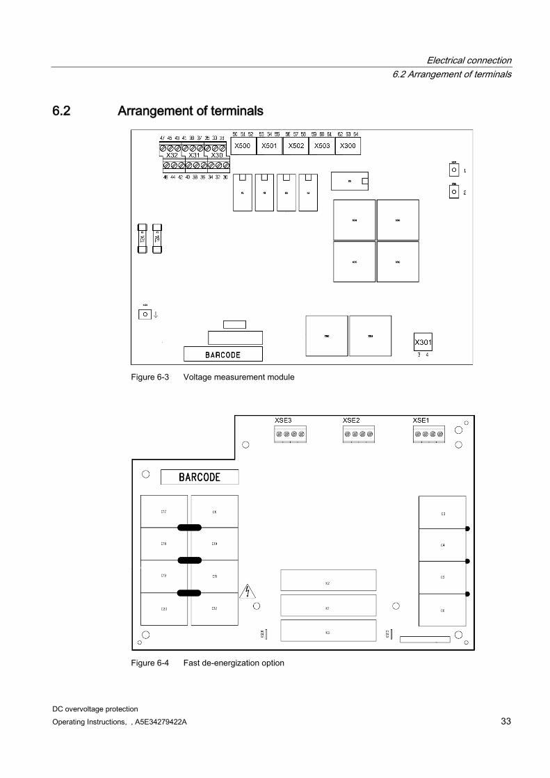
6.2 Arrangement of terminals
Figure 6-3 Voltage measurement module
Figure 6-4 Fast de-energization option
Electrical connection 6.3 Terminal description
DC overvoltage protection 34 Operating Instructions, , A5E34279422A
6.3 Terminal description
6.3.1 Terminals 3 and 4 No. Polarity Description 3 Minus Connections for external thermostatic switch
The "overload" signal is issued if this connection is interrupted. Terminal 46 switches to LOW.
4 Plus
This input is configured for secure electrical separation with a rated insulation voltage of up to 1,200 V. See Technical data (Page 61)
For a description of overload at de-energization/discharge resistor, see Monitoring functions (Page 18).
An external thermostatic switch (or several in series) can be connected to this clamp-type terminal. This provides secondary protection against overloading the resistor and must be configured for the temperature conditions.
For details on the thermostatic switch, see De-energization/discharge resistor and thermostatic switch (Page 71).
Electrical connection 6.3 Terminal description
DC overvoltage protection Operating Instructions, , A5E34279422A 35
6.3.2 Two-tier terminal 30 to 47
Table 6- 1 Power supply, status signals
No. Output name Description 47 M Electronics ground 46 UEB_INV inverse overload LOW in the event of overload, normally HIGH 45 M Electronics ground 44 DB_INV inverse wire break LOW in the event of wire break, normally HIGH 43 M Electronics ground 42 STR current flow HIGH if current flowing, normally LOW 41 M Electronics ground 40 STR_INV inverse current flow LOW if current flowing, normally HIGH 39 P_24_2 Second redundant 24 V power supply 38 M Electronics ground 37 P_24_1 First redundant 24 V power supply 36 M Electronics ground 35 STR current flow HIGH if current flowing, normally LOW 34 STR INV inverse current flow LOW if current flowing, normally HIGH 33 M Electronics ground 32 M Electronics ground 31 Housing/ground Internally connected to housing
Intended for shield grounding. 30 Housing/ground
HIGH = with feed of 24 V = 19.8 - 23.5 V, resilient up to 80 mA, short-circuit proof to electronics ground. LOW = 0 - 1 V, resilient up to 400 mA, short-circuit proof to +24 V.
The lines (terminal numbers 32 to 47) are "DVC-A (safety extra-low voltage)" and must be laid with secure electrical separation from all lines which carry line voltage.
These must be laid so that they are as separate from the electric power cables as possible. The maximum line length that can be connected is 30 m.
The device is grounded via the protective conductor connection, see Chapter PE terminal (Page 40).
Note for the configuration:
Because up to 3.2 V can drop out at internal protective elements of the outputs at 80 mA, the required operating voltage must be present across terminals 34, 40, 44, and 46 to ensure that external relays can be activated safely. We recommend activating external relays via terminals 35 and 42 as they are LOW active and the relay coils are directly connected to the P24 supply. See also Arrangement of terminals (Page 33).
Electrical connection 6.3 Terminal description
DC overvoltage protection 36 Operating Instructions, , A5E34279422A
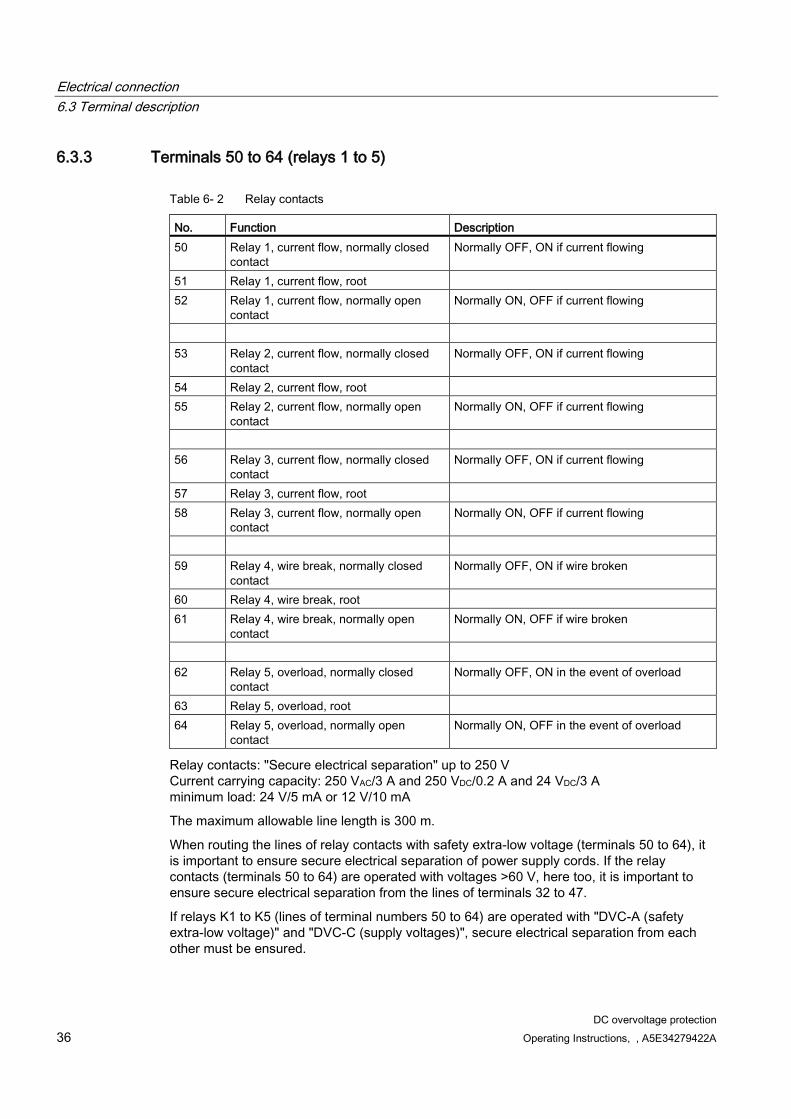
6.3.3 Terminals 50 to 64 (relays 1 to 5)
Table 6- 2 Relay contacts
No. Function Description 50 Relay 1, current flow, normally closed
contact Normally OFF, ON if current flowing
51 Relay 1, current flow, root 52 Relay 1, current flow, normally open
contact Normally ON, OFF if current flowing
53 Relay 2, current flow, normally closed
contact Normally OFF, ON if current flowing
54 Relay 2, current flow, root 55 Relay 2, current flow, normally open
contact Normally ON, OFF if current flowing
56 Relay 3, current flow, normally closed
contact Normally OFF, ON if current flowing
57 Relay 3, current flow, root 58 Relay 3, current flow, normally open
contact Normally ON, OFF if current flowing
59 Relay 4, wire break, normally closed
contact Normally OFF, ON if wire broken
60 Relay 4, wire break, root 61 Relay 4, wire break, normally open
contact Normally ON, OFF if wire broken
62 Relay 5, overload, normally closed
contact Normally OFF, ON in the event of overload
63 Relay 5, overload, root 64 Relay 5, overload, normally open
contact Normally ON, OFF in the event of overload
Relay contacts: "Secure electrical separation" up to 250 V Current carrying capacity: 250 VAC/3 A and 250 VDC/0.2 A and 24 VDC/3 A minimum load: 24 V/5 mA or 12 V/10 mA
The maximum allowable line length is 300 m.
When routing the lines of relay contacts with safety extra-low voltage (terminals 50 to 64), it is important to ensure secure electrical separation of power supply cords. If the relay contacts (terminals 50 to 64) are operated with voltages >60 V, here too, it is important to ensure secure electrical separation from the lines of terminals 32 to 47.
If relays K1 to K5 (lines of terminal numbers 50 to 64) are operated with "DVC-A (safety extra-low voltage)" and "DVC-C (supply voltages)", secure electrical separation from each other must be ensured.

Electrical connection 6.3 Terminal description
DC overvoltage protection Operating Instructions, , A5E34279422A 37
6.3.4 Settings for switch S6 for linking the inverse current flow to wire break Switch S6 must only be operated when the power unit is switched off. Closing switch S6 can link the "current flow" and "inverse current flow" signals to the "wire break" signal so that if a wire break occurs (in the wiring to the de-energization resistor) "STR current flow" is signaled. We recommend this for all systems in which a separate evaluation of the "inverse wire break" signal (relay 4 "wire break") does not take place. This does not change the logical statuses at the "inverse wire break" and "inverse overload" outputs.
Factory delivery status = switch S6 open. Always solder closed contacts.
Example for switching positions S1 to S6
Open Closed
S6
The following signal states occur at the outputs:
Table 6- 3 Signal states
Output name Physical status Switch open Switch closed Terminal no.
Signal name/ output name
Physical current flow
Physical wire break
Output not linked
Output linked
34, 40 STR INV/ inverse current flow
NO NO HIGH HIGH NO YES HIGH LOW YES NO LOW LOW YES YES LOW LOW
35, 42 STR/ current flow
NO NO LOW LOW NO YES LOW HIGH YES NO HIGH HIGH YES YES HIGH HIGH
44 DB INV/ inverse wire break
NO NO HIGH HIGH NO YES LOW LOW YES NO HIGH HIGH YES YES LOW LOW
For LOW and HIGH, see Chapter Two-tier terminal 30 to 47 (Page 35).

Electrical connection 6.3 Terminal description
DC overvoltage protection 38 Operating Instructions, , A5E34279422A
Alternative option for linking the "wire break" signal to the "current flow" signal If the relay contacts are connected as follows, the enabling circuit will be interrupted if a wire break occurs. K1, K2, K3 = current flow K4 = wire break The function at the "current flow" and "wire break" relay outputs is not changed
6.3.5 Settings for switches S1 to S5 for "current flow" pulse stretching Switches S1 to S5 may only be actuated when the power unit is switched off. Closing switches S1 to S5 can extend the active status of the "current flow" and "inverse current flow" signals. Times ranging from 1 mm to 1,500 ms can be set.
Pulse stretching table, depending on switches S1 to S5:
Table 6- 4 Pulse stretching
Switch closed Pulse stretching setpoint None *) 2 ms S1 16 ms S2 50 ms S3 100 ms S2 + S3 150 ms S4 500 ms S5 1,000 ms S4 + S5 1,500 ms *) Factory delivery status, switches S1 to S5 open
Tolerance: ± 20%
The ON time of the signal is 0.6 to 1 ms and cannot be adjusted.
For open and closed, see Figure S6 (Page 37).
Solder contacts.
Electrical connection 6.4 Power connections and terminals
DC overvoltage protection Operating Instructions, , A5E34279422A 39
6.4 Power connections and terminals
NOTICE
Connecting the unit incorrectly can lead to it being damaged or destroyed.
Power cables or busbars must be mounted or held mechanically outside of the device, and consideration must be given to the maximum short-circuit current forces that occur.
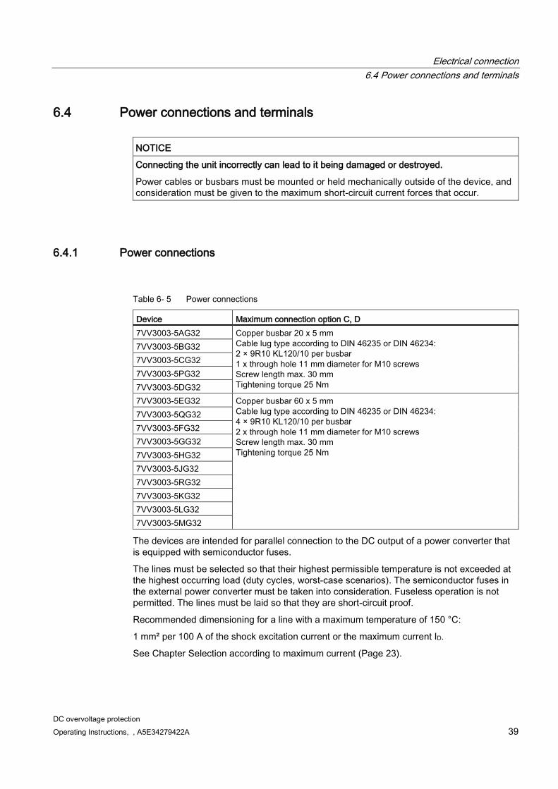
6.4.1 Power connections
Table 6- 5 Power connections
Device Maximum connection option C, D 7VV3003-5AG32 Copper busbar 20 x 5 mm
Cable lug type according to DIN 46235 or DIN 46234: 2 × 9R10 KL120/10 per busbar 1 x through hole 11 mm diameter for M10 screws Screw length max. 30 mm Tightening torque 25 Nm
7VV3003-5BG32 7VV3003-5CG32 7VV3003-5PG32 7VV3003-5DG32 7VV3003-5EG32 Copper busbar 60 x 5 mm
Cable lug type according to DIN 46235 or DIN 46234: 4 × 9R10 KL120/10 per busbar 2 x through hole 11 mm diameter for M10 screws Screw length max. 30 mm Tightening torque 25 Nm
7VV3003-5QG32 7VV3003-5FG32 7VV3003-5GG32 7VV3003-5HG32 7VV3003-5JG32 7VV3003-5RG32 7VV3003-5KG32 7VV3003-5LG32 7VV3003-5MG32
The devices are intended for parallel connection to the DC output of a power converter that is equipped with semiconductor fuses.
The lines must be selected so that their highest permissible temperature is not exceeded at the highest occurring load (duty cycles, worst-case scenarios). The semiconductor fuses in the external power converter must be taken into consideration. Fuseless operation is not permitted. The lines must be laid so that they are short-circuit proof.
Recommended dimensioning for a line with a maximum temperature of 150 °C:
1 mm² per 100 A of the shock excitation current or the maximum current ID.
See Chapter Selection according to maximum current (Page 23).
Electrical connection 6.4 Power connections and terminals
DC overvoltage protection 40 Operating Instructions, , A5E34279422A
6.4.2 PE terminal
NOTICE
The protective conductor must be installed professionally.
Ensure that the grounding conforms to standards.
For grounding, the same conductor cross-section as for power connections C, D is required. We also recommend installation on a grounded rear panel.
The connection option for grounding is at the right on the bottom edge of the device with two through holes 11 mm in diameter for M10 screws.
For connection option, see Chapter Installation (Page 29)
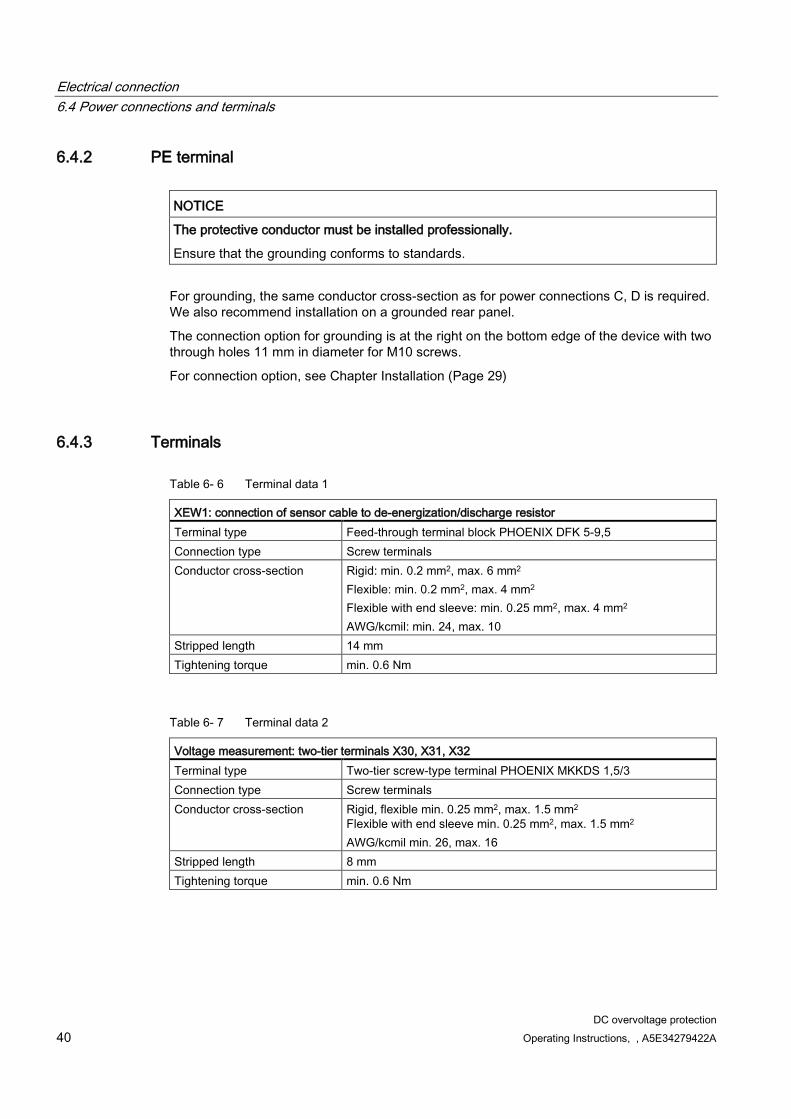
6.4.3 Terminals
Table 6- 6 Terminal data 1
XEW1: connection of sensor cable to de-energization/discharge resistor Terminal type Feed-through terminal block PHOENIX DFK 5-9,5 Connection type Screw terminals Conductor cross-section Rigid: min. 0.2 mm2, max. 6 mm2
Flexible: min. 0.2 mm2, max. 4 mm2 Flexible with end sleeve: min. 0.25 mm2, max. 4 mm2 AWG/kcmil: min. 24, max. 10
Stripped length 14 mm Tightening torque min. 0.6 Nm
Table 6- 7 Terminal data 2
Voltage measurement: two-tier terminals X30, X31, X32 Terminal type Two-tier screw-type terminal PHOENIX MKKDS 1,5/3 Connection type Screw terminals Conductor cross-section Rigid, flexible min. 0.25 mm2, max. 1.5 mm2
Flexible with end sleeve min. 0.25 mm2, max. 1.5 mm2 AWG/kcmil min. 26, max. 16
Stripped length 8 mm Tightening torque min. 0.6 Nm
Electrical connection 6.4 Power connections and terminals
DC overvoltage protection Operating Instructions, , A5E34279422A 41
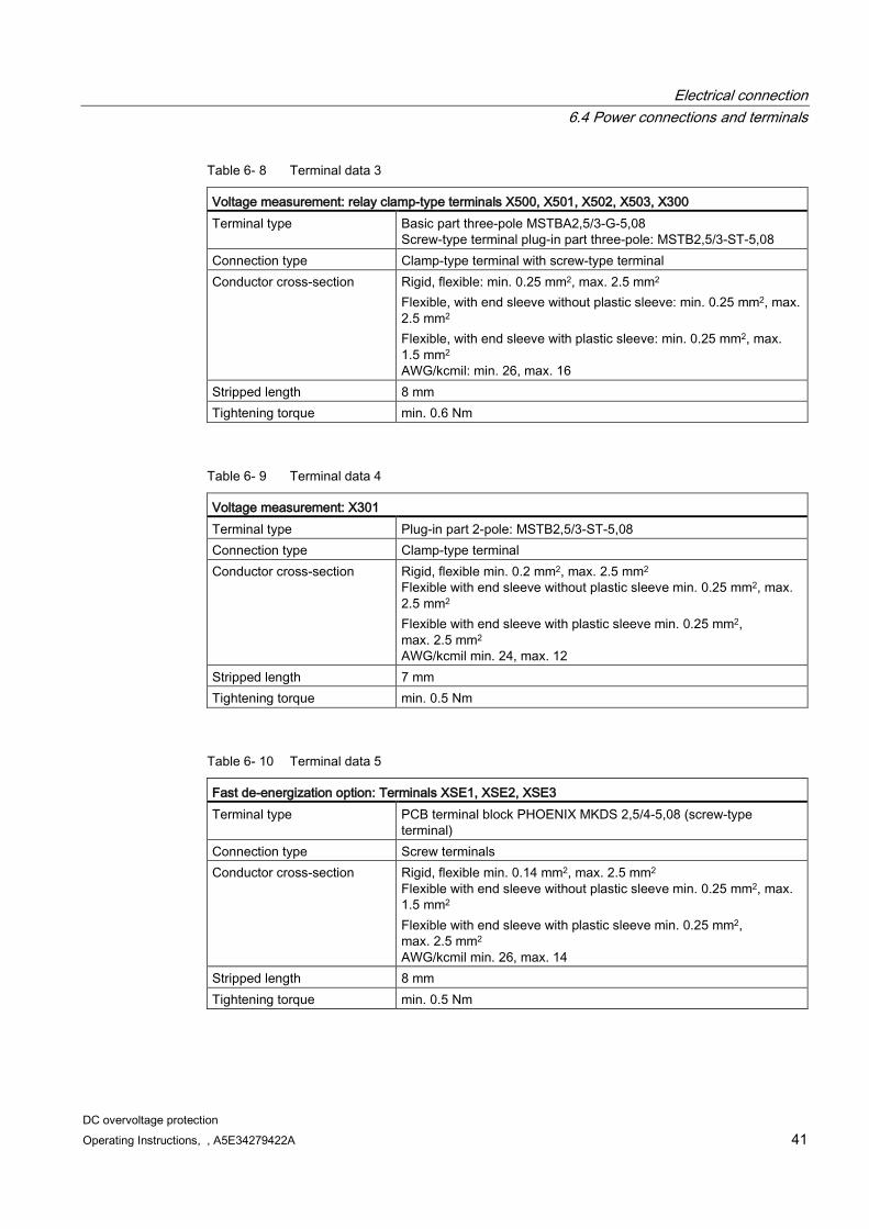
Table 6- 8 Terminal data 3
Voltage measurement: relay clamp-type terminals X500, X501, X502, X503, X300 Terminal type Basic part three-pole MSTBA2,5/3-G-5,08
Screw-type terminal plug-in part three-pole: MSTB2,5/3-ST-5,08 Connection type Clamp-type terminal with screw-type terminal Conductor cross-section Rigid, flexible: min. 0.25 mm2, max. 2.5 mm2
Flexible, with end sleeve without plastic sleeve: min. 0.25 mm2, max. 2.5 mm2 Flexible, with end sleeve with plastic sleeve: min. 0.25 mm2, max. 1.5 mm2 AWG/kcmil: min. 26, max. 16
Stripped length 8 mm Tightening torque min. 0.6 Nm
Table 6- 9 Terminal data 4
Voltage measurement: X301 Terminal type Plug-in part 2-pole: MSTB2,5/3-ST-5,08 Connection type Clamp-type terminal Conductor cross-section Rigid, flexible min. 0.2 mm2, max. 2.5 mm2
Flexible with end sleeve without plastic sleeve min. 0.25 mm2, max. 2.5 mm2 Flexible with end sleeve with plastic sleeve min. 0.25 mm2, max. 2.5 mm2 AWG/kcmil min. 24, max. 12
Stripped length 7 mm Tightening torque min. 0.5 Nm
Table 6- 10 Terminal data 5
Fast de-energization option: Terminals XSE1, XSE2, XSE3 Terminal type PCB terminal block PHOENIX MKDS 2,5/4-5,08 (screw-type
terminal) Connection type Screw terminals Conductor cross-section Rigid, flexible min. 0.14 mm2, max. 2.5 mm2
Flexible with end sleeve without plastic sleeve min. 0.25 mm2, max. 1.5 mm2 Flexible with end sleeve with plastic sleeve min. 0.25 mm2, max. 2.5 mm2 AWG/kcmil min. 26, max. 14
Stripped length 8 mm Tightening torque min. 0.5 Nm
Electrical connection 6.4 Power connections and terminals
DC overvoltage protection 42 Operating Instructions, , A5E34279422A
6.4.4 Connecting the signal lines
NOTICE
Electrostatic sensitive devices
The modules contain electrostatic sensitive devices. These components can easily be destroyed by improper handling. See also ESD precautions in Chapter Safety information (Page 9).
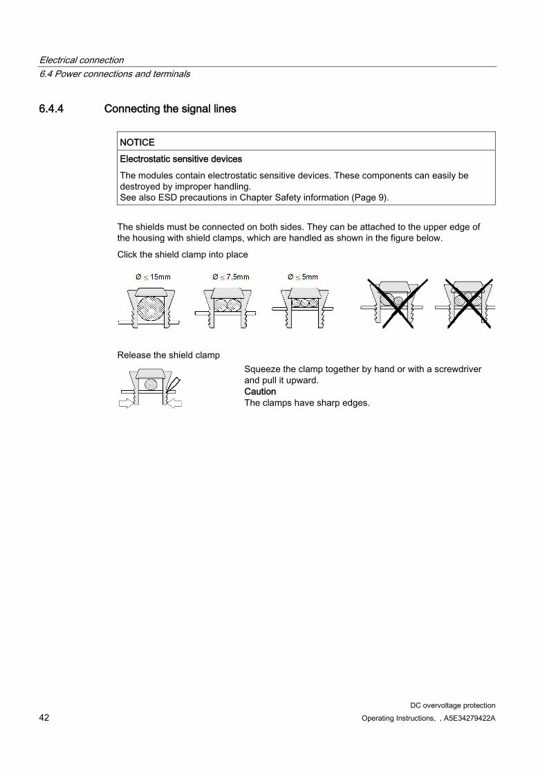
The shields must be connected on both sides. They can be attached to the upper edge of the housing with shield clamps, which are handled as shown in the figure below.
Click the shield clamp into place
Release the shield clamp
Squeeze the clamp together by hand or with a screwdriver and pull it upward. Caution The clamps have sharp edges.

DC overvoltage protection Operating Instructions, , A5E34279422A 43
Commissioning 7
NOTICE
This device contains electrostatic sensitive devices.
Before coming into contact with modules the operator must be electrostatically discharged in order to protect electronic components against high voltages that are produced by electrostatic charging. The easiest way to do this is to touch a conductive, grounded object immediately beforehand (for example, the bare metal part of a control cabinet).
Modules must not come into contact with highly insulating materials (such as plastic sheets, insulated desktops, or articles of clothing manufactured from man-made fibers).
Modules may be placed only on conductive surfaces.
WARNING
Dangerous voltages.
The device is at a hazardous voltage. Failure to comply with these Operating Instructions can lead to death, serious injury, and material damage. Only qualified personnel who are familiar with all the safety instructions in this description, as well as the installation, operating, and maintenance instructions, should carry out work on this device. Perfect, safe, and reliable operation of the device is conditional upon it having been transported, stored, mounted, and installed correctly, as well as carefully operated and serviced. The device is at a hazardous voltage even when the line contactor of the power converter device is open. Before starting maintenance or servicing work, shut down and lock all current sources for the power converter feed. These instructions are not exhaustive and as such cannot outline all the measures required in order to operate the device safely. Where necessary, additional information or instructions may be required for special applications. If particular problems arise which these Operating Instructions do not cover in enough detail, please contact your local Siemens office. The use of parts which have not been approved for repairing this device or the handling of the device by unqualified personnel can lead to dangerous conditions, death, serious injury, or substantial damage to the equipment. All safety measures listed in these Operating Instructions, as well as all warning signs attached to the device, must be followed. Observe all warnings in Chapter Safety information (Page 9) of these Operating Instructions.
Commissioning
DC overvoltage protection 44 Operating Instructions, , A5E34279422A
Commissioning:
If errors are output at the "current flow" and "inverse current flow" signals when a wire break occurs, close switch S6. See Settings for switch S6 for linking the inverse current flow to wire break (Page 37).
Connect the terminals of the output signals to the power converter. Engineering information: If current is flowing in the de-energization resistor, the power converter must be switched off at least temporarily (20 ms).
Test the "wire break" signal by interrupting the line at XEW1. The response to the "wire break" signal can last up to 3 s.
Test the "overload" signal by interrupting the lines to the thermostatic switch (if one is fitted) at terminals 3 and 4.
Set pulse stretching using S1 to S5 if necessary. See Settings for switches S1 to S5 for "current flow" pulse stretching (Page 38).
Test the behavior in the event of an electronic power supply failure. See Switching on and failure of the electronic power supply (Page 19).
The device does not have any software and there are therefore no parameters to set.
DC overvoltage protection Operating Instructions, , A5E34279422A 45
Operation 8
The DC overvoltage protection does not contain any operator controls which must be actuated during operation.
Please note the following during operation:
Cooling times after de-energization processes must be observed. See Restart time (recovery time) (Page 65).
For behavior in the event of an electronic power supply failure, see Chapter Switching on and failure of the electronic power supply (Page 19).

Operation
DC overvoltage protection 46 Operating Instructions, , A5E34279422A
DC overvoltage protection Operating Instructions, , A5E34279422A 47
Maintenance 9
WARNING
Dangerous voltages.
When operating electrical devices, it is inevitable that certain components will carry dangerous voltages.
Dangerous voltage levels may be present at the signaling relays at the customer's site.
Therefore, failure to handle the units properly can result in death or serious physical injury as well as extensive property damage.
When performing maintenance on this unit, you should therefore observe all information provided in this chapter as well as any notices attached to the product itself.
Only qualified personnel who are familiar with all the safety instructions in this description, as well as the assembly, operating, and maintenance instructions, should carry out maintenance work on this unit.
Before carrying out maintenance work, it must be ensured that the unit is disconnected from all power supplies, disabled, and grounded. Before they are shut down, both the converter unit and the excitation winding are subject to dangerous voltage levels; A hazardous voltage is present even if the converter device contactor is open.
The capacitors of the primary power converter or DC power converter connected in parallel can continue to carry a dangerous voltage for up to a minute after disconnection. Opening the device is therefore only permitted after an appropriate wait time.
Ensure safe isolation from the supply before commencing work. See Safety information (Page 9).
Use authorized spare parts only.
The device must be provided with extensive protection measures against contamination in order to prevent voltage flashovers and, therefore, destruction. Dust and foreign bodies, which are brought in by the cooling-air flow in particular, must be thoroughly removed at certain intervals; this depends on the rate of accumulation of dirt, but should be carried out at least every 12 months. The device must be blown out with dry compressed air at a maximum of 1 bar, or cleaned using a vacuum cleaner. The screw connections (also the protective conductor connections) must be retightened each time that maintenance work is carried out.
Maintenance 9.1 Replacing components
DC overvoltage protection 48 Operating Instructions, , A5E34279422A
9.1 Replacing components
WARNING
The device is at a hazardous voltage.
Modules must only be replaced by qualified personnel.
Modules must not be inserted or withdrawn under voltage.
Death, serious injury, or substantial material damage can result if these warnings are not taken into account.
The 5 safety regulations must be taken into consideration before replacement is carried out.
NOTICE
Electrostatic sensitive devices.
The modules contain electrostatic sensitive devices. Discharge yourself before touching any electronic modules. The easiest way to do this is to touch a conductive, grounded object immediately beforehand (for example, bare metal parts of control cabinet).
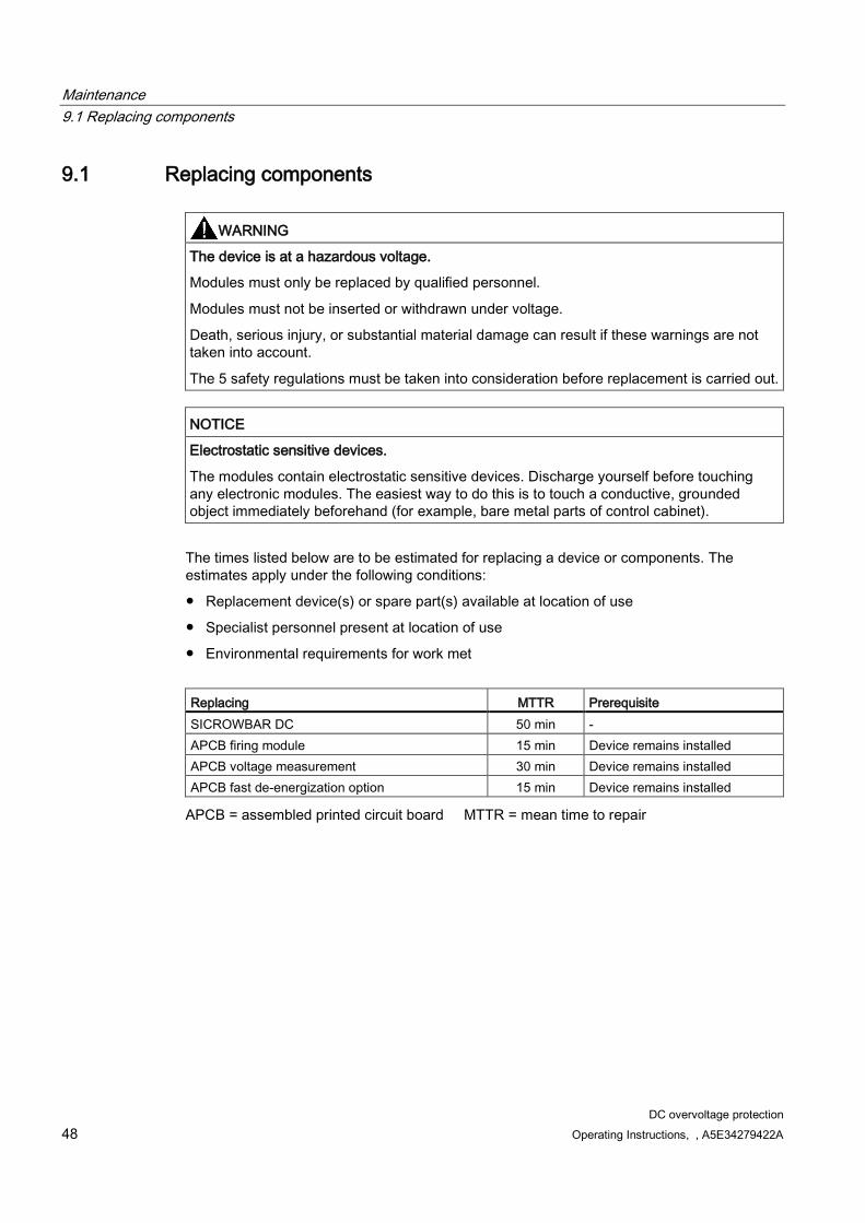
The times listed below are to be estimated for replacing a device or components. The estimates apply under the following conditions:
Replacement device(s) or spare part(s) available at location of use
Specialist personnel present at location of use
Environmental requirements for work met
Replacing MTTR Prerequisite SICROWBAR DC 50 min - APCB firing module 15 min Device remains installed APCB voltage measurement 30 min Device remains installed APCB fast de-energization option 15 min Device remains installed
APCB = assembled printed circuit board MTTR = mean time to repair

Maintenance 9.1 Replacing components
DC overvoltage protection Operating Instructions, , A5E34279422A 49
Replacing the firing module
Figure 9-1 Replacing the firing module
Carry out the following steps:
1. Record and pull out all Faston plugs (1)
2. Undo both fixing screws (2)
3. Undo both plastic spacer bolts (3)
4. Replace the assembled PCB
5. Tighten both plastic spacer bolts (3) by hand
6. Tighten both fixing screws (2) by hand
7. Attach all Faston plugs (1)
Note:
Ensure that the replacement module has the same order number (MLFB) as the original module.
Maintenance 9.1 Replacing components
DC overvoltage protection 50 Operating Instructions, , A5E34279422A
Replacing the fast de-energization option
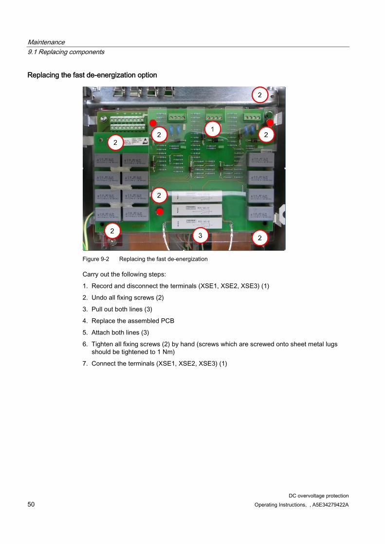
Figure 9-2 Replacing the fast de-energization
Carry out the following steps:
1. Record and disconnect the terminals (XSE1, XSE2, XSE3) (1)
2. Undo all fixing screws (2)
3. Pull out both lines (3)
4. Replace the assembled PCB
5. Attach both lines (3)
6. Tighten all fixing screws (2) by hand (screws which are screwed onto sheet metal lugs should be tightened to 1 Nm)
7. Connect the terminals (XSE1, XSE2, XSE3) (1)
Maintenance 9.1 Replacing components
DC overvoltage protection Operating Instructions, , A5E34279422A 51
Replacing the voltage measurement
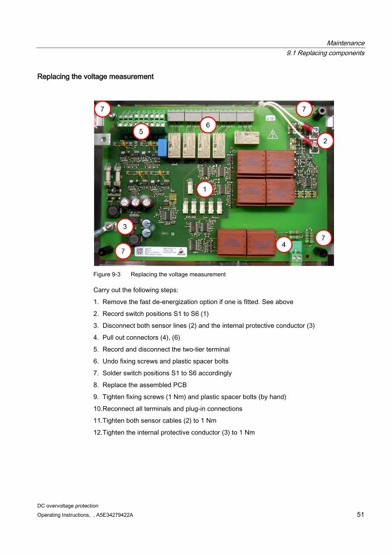
Figure 9-3 Replacing the voltage measurement
Carry out the following steps:
1. Remove the fast de-energization option if one is fitted. See above
2. Record switch positions S1 to S6 (1)
3. Disconnect both sensor lines (2) and the internal protective conductor (3)
4. Pull out connectors (4), (6)
5. Record and disconnect the two-tier terminal
6. Undo fixing screws and plastic spacer bolts
7. Solder switch positions S1 to S6 accordingly
8. Replace the assembled PCB
9. Tighten fixing screws (1 Nm) and plastic spacer bolts (by hand)
10.Reconnect all terminals and plug-in connections
11.Tighten both sensor cables (2) to 1 Nm
12.Tighten the internal protective conductor (3) to 1 Nm

Maintenance 9.1 Replacing components
DC overvoltage protection 52 Operating Instructions, , A5E34279422A

DC overvoltage protection Operating Instructions, , A5E34279422A 53
Spare parts 10
Identifier
Dimensions L×W×H (mm)
Weight (kg)
Order number (MLFB)
Used in 7VV3003-..
APCB firing circuit 800 V 160×100×25 0.1 7VV3003-7FA00 ..5AG32 APCB firing circuit 1,200 V 160×100×25 0.1 7VV3003-7FB00 ..5BG32 APCB firing circuit 1,600 V
160×100×25 0.1 7VV3003-7FC00 ..5CG32 ..5EG32 ..5JG32
APCB firing circuit 1,900 V
160×100×25 0.1 7VV3003-7FH00 ...5PG32 ...5QG32 ...5RG32
APCB firing circuit 2,200 V
160×100×25 0.1 7VV3003-7FD00 ..5DG32 ..5FG32 ..5KG32
APCB firing circuit 2,600 V
160×100×25 0.1 7VV3003-7FE00 ..5GG32 ..5LG32
APCB firing circuit 3,000 V
160×100×25 0.1 7VV3003-7FF00 ..5HG32 ..5MG32
APCB voltage measurement
233×160×30 0.4 7VV3003-7VS00 All types
Option G11 APCB fast de-energization option
233×160×40 0.5 7VV3003-7FG00 All types

Spare parts
DC overvoltage protection 54 Operating Instructions, , A5E34279422A
DC overvoltage protection Operating Instructions, , A5E34279422A 55
Disposal 11
Environmental aspects during development
The use of highly-integrated components has enabled the number of parts to be kept to a minimum, with energy being used as efficiently as possible during production as a result.
Particular attention has been paid to reducing the volume, mass, and type variety of metal and plastic parts.
Front parts: PC + ABS Cycoloy GE-Plastics ABS Novodur Bayer Plastic parts in the unit:
PC Lexan 141-R
PA 6.6 SE1-GFN1 Noryl Insulation materials: PC (FR) fl Makrolon or
Lexan
Rating plate: Polyester film
Materials free of hazardous substances have been used for all of the essential parts. No flame retardants containing halogen or insulation materials containing silicon have been used.
Environmental compatibility was a key criterion in selecting supplier parts.
Environmental aspects during production
The majority of supplier parts are transported in reusable packaging. The packing material itself is recyclable, and consists mainly of cardboard.
With the exception of the enclosure, no surface coatings have been used.
The production processes do not produce any emissions.
Environmental aspects during disposal
The device features screw-in and snap-in connections that can be easily released in order to separate it into different mechanical components for recycling purposes. The assembled PCBs must be disposed of in accordance with local regulations.

Disposal
DC overvoltage protection 56 Operating Instructions, , A5E34279422A
Certificates:
The products listed in this document are manufactured and sold according to the following certificates:
Environmental management: ISO 14001:2004
Quality management: ISO 9001:2008
Security management: BS OHSAS 18001:2007

Disposal
DC overvoltage protection Operating Instructions, , A5E34279422A 57

DC overvoltage protection Operating Instructions, , A5E34279422A 59
Service and Support A A.1 Service
Note We would be grateful if you could specify the following unit data when you have any queries: • Device order number and serial number • Execution status of the modules • MLFB of the APCBs
Siemens supplies intensively tested, high-quality products and systems. We offer comprehensive services to ensure maximum availability of our products and systems in your facility.
You can find information on our services and regional contact persons on the Internet at:
(http://www.siemens.de/automation/csi_de/service)
A.2 Technical Support Our customer support service can provide you with technical assistance for products, systems, and solutions. This service is available in German and in English.
Europe and Africa time zone: 7:00 to 17:00 (CET)
Tel.: +49 911 895 7222 Fax: +49 911 895 7223 mailto: ([email protected])
America time zone: 8:00 to 17:00 (local time: Eastern Standard Time) Tel.: +1 423 262 2960 24-hour hotline: +1 800 333 7421 Fax: +1423 262 2200 mailto: ([email protected])
Asia/Australia time zone: 7:30 to 17:30 (local time: Beijing) Tel.: +86 1064 757575 Fax: +86 1064 747474 mailto: ([email protected])

Service and Support A.3 Service calls
DC overvoltage protection 60 Operating Instructions, , A5E34279422A
A.3 Service calls Qualified personnel can perform repair work on your units and offer services that ensure their availability. For service calls, contact your regional contact person.
DC overvoltage protection Operating Instructions, , A5E34279422A 61
Technical specifications and drawings B B.1 Technical data
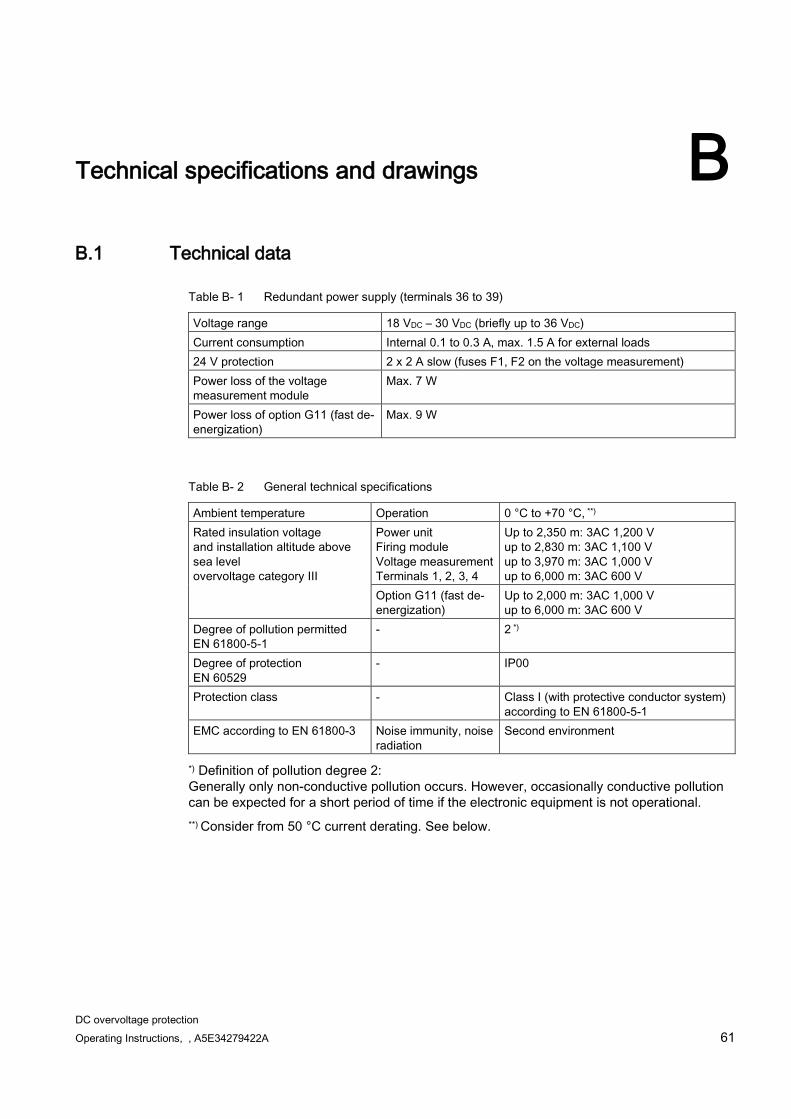
Table B- 1 Redundant power supply (terminals 36 to 39)
Voltage range 18 VDC – 30 VDC (briefly up to 36 VDC) Current consumption Internal 0.1 to 0.3 A, max. 1.5 A for external loads 24 V protection 2 x 2 A slow (fuses F1, F2 on the voltage measurement) Power loss of the voltage measurement module
Max. 7 W
Power loss of option G11 (fast de-energization)
Max. 9 W
Table B- 2 General technical specifications
Ambient temperature Operation 0 °C to +70 °C, **) Rated insulation voltage and installation altitude above sea level overvoltage category III
Power unit Firing module Voltage measurement Terminals 1, 2, 3, 4
Up to 2,350 m: 3AC 1,200 V up to 2,830 m: 3AC 1,100 V up to 3,970 m: 3AC 1,000 V up to 6,000 m: 3AC 600 V
Option G11 (fast de-energization)
Up to 2,000 m: 3AC 1,000 V up to 6,000 m: 3AC 600 V
Degree of pollution permitted EN 61800-5-1
- 2 *)
Degree of protection EN 60529
- IP00
Protection class - Class I (with protective conductor system) according to EN 61800-5-1
EMC according to EN 61800-3 Noise immunity, noise radiation
Second environment
*) Definition of pollution degree 2: Generally only non-conductive pollution occurs. However, occasionally conductive pollution can be expected for a short period of time if the electronic equipment is not operational. **) Consider from 50 °C current derating. See below.

Technical specifications and drawings B.1 Technical data
DC overvoltage protection 62 Operating Instructions, , A5E34279422A
Table B- 3 Environmental classes according to EN 60721-3
Application
Environmental conditions
Environmental class
Remarks
Operation Mechanical stability See remark • Vibratory load (testing and measuring procedure according to EN 60068-2-6, Fc): Constant deflection = 0.075 mm at 10...58 Hz Constant acceleration = 10 m/s2 at 58...200 Hz
• Shock load (testing and measuring procedure according to EN 60068-2-27, Ea): Acceleration = 150 m/s2 at 11 ms
Climatic influences 3K3 Air temperature range up to +70 °C is permitted Biological influences 3B1 - Hazardous chemicals 3C1 - Mechanically hazardous materials
3S2 -
Transport Mechanical stability 2M2 Tipping is not permitted Climatic influences 2K2 Air temperature range from -40 °C to +70 °C is
permitted ***) Biological influences 2B1 - Hazardous chemicals 2C1 - Mechanically hazardous materials
2S1 -
Storage Mechanical stability 1M2 Tipping is not permitted Climatic influences 1K3 Air temperature range from 40 °C to +70 °C is
permitted ***) Biological influences 1B1 - Hazardous chemicals 1C1 - Mechanically hazardous materials
1S1 -
***) Only applies when product is in its original packing
Table B- 4 Current derating as a function of the air intake temperature
Air intake temperature Current derating *) 50 °C 0% 60 °C -8% 70 °C -16%
*) Affects the maximum pulse current according to: Technical specifications of the power unit (1-3) and Figure B-1 Load current characteristic (Page 65).
Technical specifications and drawings B.1 Technical data
DC overvoltage protection Operating Instructions, , A5E34279422A 63
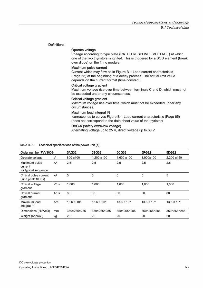
Definitions Operate voltage
Voltage according to type plate (RATED RESPONSE VOLTAGE) at which one of the two thyristors is ignited. This is triggered by a BOD element (break over diode) on the firing module.
Maximum pulse current Current which may flow as in Figure B-1 Load current characteristic (Page 65) at the beginning of a decay process. The actual limit value depends on the current format (time constant).
Critical voltage gradient Maximum voltage rise over time between terminals C and D, which must not be exceeded under any circumstances.
Critical voltage gradient Maximum voltage rise over time, which must not be exceeded under any circumstances.
Maximum load integral I2t corresponds to curves Figure B-1 Load current characteristic (Page 65) (does not correspond to the data sheet value of the thyristor)
DVC-A (safety extra-low voltage) Alternating voltage up to 25 V, direct voltage up to 60 V
Table B- 5 Technical specifications of the power unit (1)
Order number 7VV3003- 5AG32 5BG32 5CG32 5PG32 5DG32 Operate voltage V 800 ±100 1,200 ±100 1,600 ±100 1,900±100 2,200 ±150 Maximum pulse current for typical sequence
kA 2.5 2.5 2.5 2.5 2.5
Critical pulse current (sine peak 10 ms)
kA 5 5 5 5 5
Critical voltage gradient
V/µs 1,000 1,000 1,000 1,000 1,000
Critical current gradient
A/µs 80 80 80 80 80
Maximum load integral I2t
A2s 13.6 × 10⁶ 13.6 × 10⁶ 13.6 × 10⁶ 13.6 × 10⁶ 13.6 × 10⁶
Dimensions (HxWxD) mm 350×265×285 350×265×285 350×265×285 350×265×285 350×265×285 Weight (approx.) kg 20 20 20 20 20

Technical specifications and drawings B.1 Technical data
DC overvoltage protection 64 Operating Instructions, , A5E34279422A
Table B- 6 Technical specifications of the power unit (2)
Order number 7VV3003- 5EG32 5QG32 5FG32 5GG32 5HG32 Operate voltage V 1,600 ±100 1,900 ±100 2,200 ±150 2,600 ±150 3,000 ±150 Maximum pulse current for typical sequence
kA 5.8 5.8 5.8 5.8 5.8
Critical pulse current (sine peak 10 ms)
kA 11.6 11.6 11.6 11.6 11.6
Critical voltage gradient
V/µs 1,000 1,000 1,000 1,000 1,000
Critical current gradient
A/µs 300 300 300 300 300
Maximum load integral I2t
A2s 73 × 106 73 × 106 73 × 106 73 × 106 73 × 106
Dimensions (HxWxD) mm 350×265×285 350×265×285 350×265×285 350×265×285 350×265×285 Weight (approx.) kg 23 23 23 23 23
Table B- 7 Technical specifications of the power unit (3)
Order number 7VV3003- 5JG32 5RG32 5KG32 5LG32 5MG32 Operate voltage V 1,600 ±100 1,900±100 2,200 ±150 2,600 ±150 3,000 ±150 Maximum pulse current for typical sequence
kA 10.5 10.5 10.5 10.5 10.5
Critical pulse current (sine peak 10 ms)
kA 21 21 21 21 21
Critical voltage gradient
V/µs 1,000 1,000 1,000 1,000 1,000
Critical current gradient
A/µs 300 300 300 300 300
Maximum load integral I2t
A2s 239 × 106 239 × 106 239 × 106 239 × 106 239 × 106
Dimensions (HxWxD) mm 350×265×285 350×265×285 350×265×285 350×265×285 350×265×285 Weight (approx.) kg 24 24 24 24 24

Technical specifications and drawings B.2 Typical load current characteristic for the three device power stages
DC overvoltage protection Operating Instructions, , A5E34279422A 65
B.2 Typical load current characteristic for the three device power stages
Figure B-1 Load current characteristic
B.3 Restart time (recovery time)
Single tripping is periodically possible after 30 min wait time.
After being triggered twice in a time period <30 min, a recovery time of 300 min is required.
* = Tripping the SICROWBAR DC overvoltage protection
There are multiple cases in which current flows through the SICROWBAR and thus causes the external resistor to heat up:
Technical specifications and drawings B.3 Restart time (recovery time)
DC overvoltage protection 66 Operating Instructions, , A5E34279422A
1. De-energization according to e-potency in fast de-energization if it is not possible to feed back via the power converter.
2. Generator slips: The generator is disconnected from the line supply system after 200 ms for mechanical reasons. A current of 11 kA can flow at this time. The resistor should be thermally configured for 2 x 200 ms.
3. Ignited by the overvoltage pulse on the line. The power converter consequently feeds to the de-energization resistor. Significant and sustained power loss occurs depending on the load point. This operation should be avoided by immediately limiting the power converter to remove the thyristor in SICROWBAR.
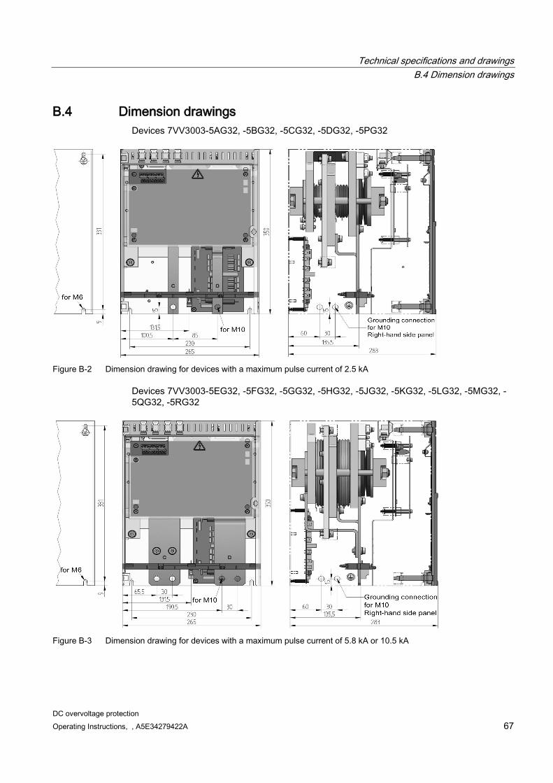
Technical specifications and drawings B.4 Dimension drawings
DC overvoltage protection Operating Instructions, , A5E34279422A 67
B.4 Dimension drawings Devices 7VV3003-5AG32, -5BG32, -5CG32, -5DG32, -5PG32
Figure B-2 Dimension drawing for devices with a maximum pulse current of 2.5 kA
Devices 7VV3003-5EG32, -5FG32, -5GG32, -5HG32, -5JG32, -5KG32, -5LG32, -5MG32, -5QG32, -5RG32
Figure B-3 Dimension drawing for devices with a maximum pulse current of 5.8 kA or 10.5 kA
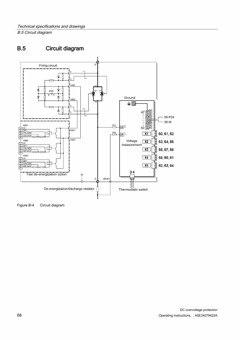
Technical specifications and drawings B.5 Circuit diagram
DC overvoltage protection 68 Operating Instructions, , A5E34279422A
B.5 Circuit diagram
Figure B-4 Circuit diagram

DC overvoltage protection Operating Instructions, , A5E34279422A 69
Appendix C C
Empty chapter.

Appendix C
DC overvoltage protection 70 Operating Instructions, , A5E34279422A

DC overvoltage protection Operating Instructions, , A5E34279422A 71
Additional documents D D.1 De-energization/discharge resistor and thermostatic switch
The following components are described as examples:
Discharge resistor Company: GINO Type: 3PR3001-1K-1R17 (1.17 Ω) Other types: 3PR3001-1M 2R3, 3PR3801-1B 0R24, 3PR3401-1F 0R6
Thermostatic switch: Company: Microtherm Type: R28-160 05 J Ö TR/STD 52N121934
Selecting the de-energization resistor After determining the resistance value according to Chapter Selection according to maximum current (Page 23), the size (frame size) of the resistor must be selected so that the highest permissible temperature of the cast iron elements (approx. 300 °C) is not exceeded at the highest load that occurs (duty cycle, worst-case scenarios).
Selecting the thermostatic switch The connection lines of the thermostatic switch must be configured for short-term heating to 300 °C. The lines must be laid so that they are in hot air currents as little as possible. The switching threshold of the thermostatic switch must be set so as to prevent damage (crack formation) to the cast iron elements.
Recommended thermostatic switch with 160 °C from Microtherm
Order key: R28-160 05 J Ö TR/STD 52N121934
Microtherm type: R28
Temperature: 160
Tolerance: 05
NC contact: NC reset temperature (standard): TR/STD
Design type (ceramic): 52N
Base plate with mounting: 121
Plug connection: 934, contacts
Crossbar (P for low voltage)
Hysteresis: "Normal"
Additional information
Additional documents D.1 De-energization/discharge resistor and thermostatic switch
DC overvoltage protection 72 Operating Instructions, , A5E34279422A
The connections are made using Faston tabs (6.3 mm).
Lines for making connections with Faston plugs: Nickel wire 1.5 mm², NiMoGi/ m type, flexible, white
Installing the thermostatic switch The de-energization resistor and the thermostatic switch must be installed correctly so that the rising temperature can be correctly detected and to ensure that the thermostatic switch functions. The lines must be laid in parallel.
The thermostatic switch is mounted on a mounting bracket in the center of the upper crossbar. The vertical distance from the cast iron elements must be at least 19 mm. This gives an air clearance for double/enforced insulation for 1,200 V for an installation altitude of up to 2,775 m. The heat-resistant lines from the thermostatic switch are laid to a junction terminal.
The lines must be laid from the junction terminal to the APCB with one of the following:
NYM-J (sheathed cable 300 V)
H07R (line 750 V)
If multiple de-energization resistors are to be connected in parallel, we recommend installing a thermostatic switch on each resistor and connecting them in series. The cumulative resistance of the external thermostatic switches and lines connected in series must not exceed 100 Ω.
Additional notes:
The bracket must be reinforced in the corners so that it is not easy to bend out of shape either after or during installation.
A second mounting bracket must also be installed for fastening the line.
A complete package can be ordered from GINO AG using the order number 132501. It contains the following components:
Thermostatic switch 160 °C
Mounting bracket for thermostatic switch
Mounting bracket for line
Cable 300 °C
Ceramic junction terminal

Additional documents D.1 De-energization/discharge resistor and thermostatic switch
DC overvoltage protection Operating Instructions, , A5E34279422A 73
Figure D-1 Installing the thermostatic switch
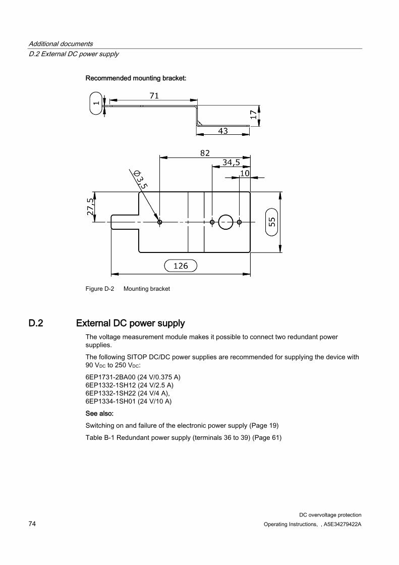
Additional documents D.2 External DC power supply
DC overvoltage protection 74 Operating Instructions, , A5E34279422A
Recommended mounting bracket:
Figure D-2 Mounting bracket
D.2 External DC power supply The voltage measurement module makes it possible to connect two redundant power supplies.
The following SITOP DC/DC power supplies are recommended for supplying the device with 90 VDC to 250 VDC:
6EP1731-2BA00 (24 V/0.375 A) 6EP1332-1SH12 (24 V/2.5 A) 6EP1332-1SH22 (24 V/4 A), 6EP1334-1SH01 (24 V/10 A)
See also:
Switching on and failure of the electronic power supply (Page 19)
Table B-1 Redundant power supply (terminals 36 to 39) (Page 61)


Siemens AGIndustry SectorPostfach 48 4890026 NÜRNBERGDEUTSCHLAND
Subject to change without prior notice© Siemens AG 2014
DC overvoltage protectionSICROWBAR DC
www.siemens.com/automation