DC Main Circuit Protection - the fuses and circuit ... Htmls/pdf/Switches/Blue Sea/DC_Main_2... ·...
11
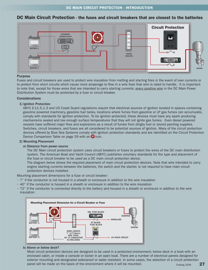
DC MAIN CIRCUIT PROTECTION - INTRODUCTION Purpose Fuses and circuit breakers are used to protect wire insulation from melting and starting fires in the event of over currents or to protect from short circuits which cause more amperage to flow in a wire than that wire is rated to handle. It is important to note that, except for those wires that are intended to carry starting currents, every positive wire in the DC Main Power Distribution System must be protected by a fuse or circuit breaker. Considerations 1) Ignition Protection ABYC E-11.5.1.3 and US Coast Guard regulations require that electrical sources of ignition located in spaces containing gasoline powered machinery, gasoline fuel tanks, locations where fumes from gasoline or LP gas fumes can accumulate, comply with standards for ignition protection. To be ignition protected, these devices must have any spark producing mechanisms sealed and low enough surface temperatures that they will not ignite gas fumes. Even diesel powered vessels have suffered major fires and explosions as a result of fumes from dinghy fuel or stored painting supplies. Switches, circuit breakers, and fuses are all considered to be potential sources of ignition. Many of the circuit protection devices offered by Blue Sea Systems comply with ignition protection standards and are identified on the Circuit Protection Device Comparison Table on page 29 with an icon. 2) Mounting Placement a) Distance from power source The DC Main circuit protection system uses circuit breakers or fuses to protect the wires of the DC main distribution system. The American Boat and Yacht Council (ABYC) publishes voluntary standards for the type and placement of the fuse or circuit breaker to be used as a DC main circuit protection device. The diagram below shows the required placement of main circuit protection devices. Note that wire intended to carry engine starting currents between the batteries, the switch and the starter, is not required to have main circuit protection devices installed. Mounting placement dimensions for a fuse or circuit breaker: • 7” if the conductor is not housed in a sheath or enclosure in addition to the wire insulation • 40” if the conductor is housed in a sheath or enclosure in addition to the wire insulation • 72” if the conductor is connected directly to the battery and housed in a sheath or enclosure in addition to the wire insulation b) Above or below deck? Most circuit protection devices are designed to be used in a protected environment; below deck in a boat with an enclosed cabin, or inside a console or locker in an open boat. There are a number of electrical panels designed for exterior mounting and designated waterproof or water resistant. In some cases, the selection of a circuit protection panel will be made on the basis of the environment where it will be mounted. Catalog 2006 27 Mounting Placement Dimension for a Circuit Breaker or Fuse BATTERY 1 BATTERY 2 ANL FUSE BLOCK ST BLADE FUSE BLOCK WINDLASS 24 HOUR CIRCUIT STARTER ENGINE WIRE LENGTH 7” (177.8mm) MAY TOTAL 40” IF CONDUCTOR IS ENCLOSED DC Main Circuit Protection - the fuses and circuit breakers that are closest to the batteries AUTOMATIC CHARGE RELAY BATTERY 1 BATTERY 2 HOUSE CIRCUITS ENGINE Circuit Protection
Transcript of DC Main Circuit Protection - the fuses and circuit ... Htmls/pdf/Switches/Blue Sea/DC_Main_2... ·...
DC MAIN CIRCUIT PROTECTION - INTRODUCTION
PurposeFuses and circuit breakers are used to protect wire insulation from melting and starting fi res in the event of over currents or to protect from short circuits which cause more amperage to fl ow in a wire than that wire is rated to handle. It is important to note that, except for those wires that are intended to carry starting currents, every positive wire in the DC Main Power Distribution System must be protected by a fuse or circuit breaker. Considerations 1) Ignition Protection ABYC E-11.5.1.3 and US Coast Guard regulations require that electrical sources of ignition located in spaces containing gasoline powered machinery, gasoline fuel tanks, locations where fumes from gasoline or LP gas fumes can accumulate, comply with standards for ignition protection. To be ignition protected, these devices must have any spark producing mechanisms sealed and low enough surface temperatures that they will not ignite gas fumes. Even diesel powered vessels have suffered major fi res and explosions as a result of fumes from dinghy fuel or stored painting supplies. Switches, circuit breakers, and fuses are all considered to be potential sources of ignition. Many of the circuit protection devices offered by Blue Sea Systems comply with ignition protection standards and are identifi ed on the Circuit Protection Device Comparison Table on page 29 with an icon. 2) Mounting Placement a) Distance from power source The DC Main circuit protection system uses circuit breakers or fuses to protect the wires of the DC main distribution system. The American Boat and Yacht Council (ABYC) publishes voluntary standards for the type and placement of the fuse or circuit breaker to be used as a DC main circuit protection device.
The diagram below shows the required placement of main circuit protection devices. Note that wire intended to carry engine starting currents between the batteries, the switch and the starter, is not required to have main circuit protection devices installed.
Mounting placement dimensions for a fuse or circuit breaker: • 7” if the conductor is not housed in a sheath or enclosure in addition to the wire insulation• 40” if the conductor is housed in a sheath or enclosure in addition to the wire insulation• 72” if the conductor is connected directly to the battery and housed in a sheath or enclosure in addition to the wire insulation
b) Above or below deck? Most circuit protection devices are designed to be used in a protected environment; below deck in a boat with an enclosed cabin, or inside a console or locker in an open boat. There are a number of electrical panels designed for exterior mounting and designated waterproof or water resistant. In some cases, the selection of a circuit protection panel will be made on the basis of the environment where it will be mounted. Catalog 2006 27
Mounting Placement Dimension for a Circuit Breaker or Fuse
BATTERY 1
BATTERY 2
ANL FUSE BLOCK
ST BLADE FUSE BLOCK
WINDLASS
24 HOUR CIRCUIT
STARTER
ENGINE
WIRE LENGTH7” (177.8mm)
MAY TOTAL40” IF CONDUCTOR
IS ENCLOSED
DC Main Circuit Protection - the fuses and circuit breakers that are closest to the batteries
AUTOMATIC CHARGE RELAY
BATTERY 1
BATTERY 2
HOUSECIRCUITS
ENGINE
Circuit Protection

DC MAIN CIRCUIT PROTECTION - INTRODUCTION
28 Blue Sea Systems
Selecting DC Main Circuit Protection DC Main Circuit Protection Devices are characterized by one principal attribute, their Ampere Interrupt Capacity (AIC) rating. Specifi cations listed in the ABYC standards determine the AIC a Main Circuit Protection Device must have. The total Cold Cranking Amperes (CCA) of the batteries installed that can be connected to the circuit to be protected determine the required AIC rating. See the tables on the following page, for the required AIC ratings.
Allowable amperage of conductors under 50 Volts with 105°C insulation
AWGWire Size
Metric(Sq mm)
AWGCM Area
SAECM Area
Ohms/1000ft
Ampacity Engine Space
Outside Inside
18 0.8 1,600 1,537 6.385 20 17
16 1 2,600 2,336 4.016 25 21
14 2 4,100 3,702 2.525 35 29
12 3 6,500 5,833 1.588 45 38
10 5 10,500 9,343 0.9989 60 51
8 8 16,800 14,810 0.6282 80 68
6 13 26,600 24,538 0.3951 120 102
4 19 42,000 37,360 0.2485 160 136
2 32 66,500 62,450 0.1563 210 178
1 40 83,690 77,790 0.1239 245 208
0 50 105,600 98,980 0.09827 285 242
2/0 62 133,100 125,100 0.07793 330 280
3/0 81 167,800 158,600 0.06180 385 327
4/0 103 211,600 205,500 0.04901 445 378
Questions to answer when selecting the type and size of fuse or circuit breaker: 1) Do I need a fuse or circuit breaker? Fuse advantages: Circuit Breaker advantages: • Generally lower cost • Re-settable after opening • Available in higher amperage ratings • Can be used as a switch • Available in higher interrupt ratings • Available in vaporproof or waterproof models • Available in greater size ranges • A wide range of opening speed characteristics are available
If the application requires the circuit protection device to be in an explosive area, as in a, b, or c below, then an ignition protected circuit breaker or fuse is required: a) Gasoline engine room or other area susceptible to gasoline fumes b) Battery compartments c) Propane lockers 2) What Interrupt Rating or Ampere Interrupt Capacity (AIC) is required? See the ABYC Interrupt Rating Table on the following page. Limit the selection to a fuse or circuit breaker type that meets the AIC of each. 3) What type of circuit protection device meets the AIC rating requirements from step 2? See the Circuit Protection Device Comparison Table on the following page. 4) Does the circuit protection device need to be ignition protected? See the icon on the Circuit Protection Comparison Table on following page. 5) What should the appropriate Amperage rating be for the circuit protection device? a) The rating must be lower than the ampacity of the smallest wire in the circuit. See the ABYC Ampacity Rating Table below. b) The rating must be higher than the maximum continuous current that will fl ow in the circuit.
* Special considerations should be made for electrical systems that exceed 32 Volts** There are other issues that may be considered by reading ABYC E-11.12 circuit protection
* Thermally limited amperage capacity
c) Wire Installation Most circuit protection devices suitable for marine use are designed to have wires connected using ring terminals, but a few are designed to accept push-on connectors. Because large wire sizes may be chosen to minimize voltage drop in low voltage DC systems, the wire choice may make one circuit protection device more suitable than another. If large conductors are used, you may want to choose protective devices that can accommodate and support larger wire. In some cases the wire may be so large that it is necessary to place a power post or wire connection point near the circuit protection device and transition from the large wire to a smaller wire to connect to the protection device.
ABYC Ampacity* Rating Table
Specifi cations subject to change. See www.bluesea.com for current information. Catalog 2006 29
DC MAIN CIRCUIT PROTECTION - INTRODUCTION
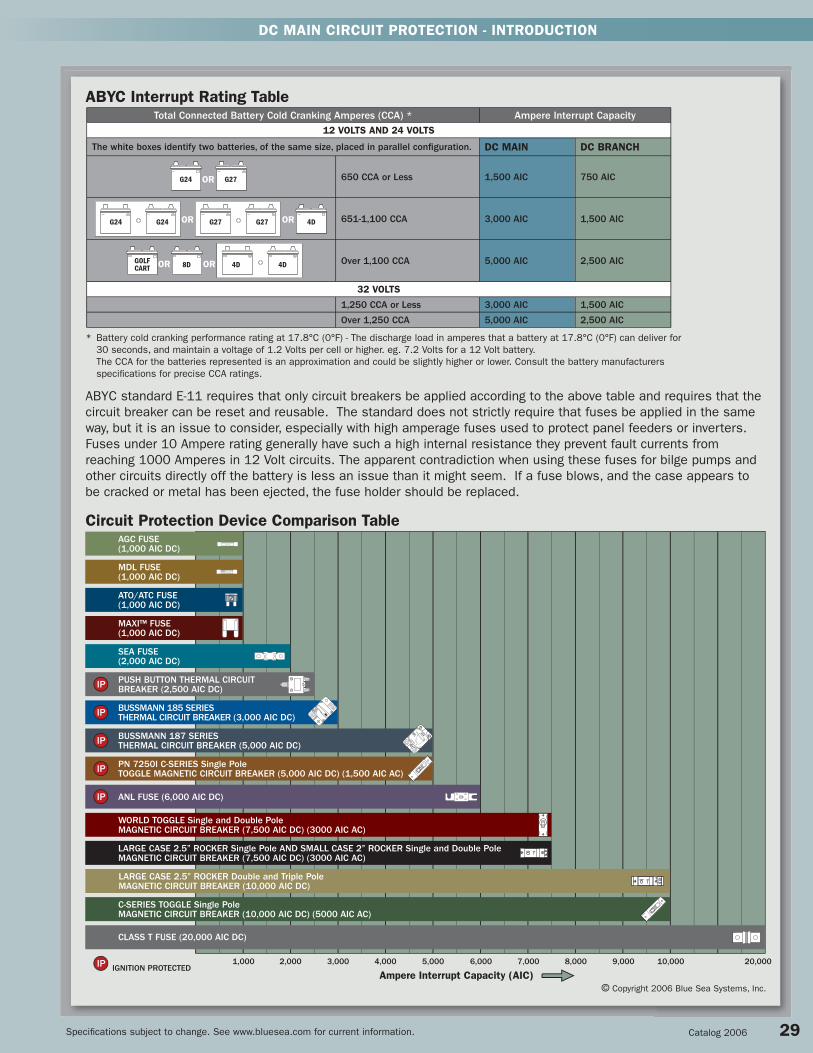
Circuit Protection Device Comparison Table
Ampere Interrupt Capacity (AIC)
IGNITION PROTECTED1,000 2,000 3,000 4,000 5,000 6,000 7,000 8,000 9,000 10,000 20,000
© Copyright 2006 Blue Sea Systems, Inc.
MDL FUSE(1,000 AIC DC)
AGC FUSE(1,000 AIC DC)
ATO/ATC FUSE(1,000 AIC DC)
SEA FUSE(2,000 AIC DC)
CLASS T FUSE (20,000 AIC DC)
ANL FUSE (6,000 AIC DC)
PUSH BUTTON THERMAL CIRCUIT BREAKER (2,500 AIC DC)
LARGE CASE 2.5” ROCKER Single Pole AND SMALL CASE 2” ROCKER Single and Double Pole MAGNETIC CIRCUIT BREAKER (7,500 AIC DC) (3000 AIC AC)
WORLD TOGGLE Single and Double PoleMAGNETIC CIRCUIT BREAKER (7,500 AIC DC) (3000 AIC AC)
BUSSMANN 187 SERIES THERMAL CIRCUIT BREAKER (5,000 AIC DC)
BUSSMANN 185 SERIES THERMAL CIRCUIT BREAKER (3,000 AIC DC)
C-SERIES TOGGLE Single Pole MAGNETIC CIRCUIT BREAKER (10,000 AIC DC) (5000 AIC AC)
PN 7250I C-SERIES Single PoleTOGGLE MAGNETIC CIRCUIT BREAKER (5,000 AIC DC) (1,500 AIC AC)
MAXI™ FUSE(1,000 AIC DC)
* Battery cold cranking performance rating at 17.8°C (0°F) - The discharge load in amperes that a battery at 17.8°C (0°F) can deliver for 30 seconds, and maintain a voltage of 1.2 Volts per cell or higher. eg. 7.2 Volts for a 12 Volt battery. The CCA for the batteries represented is an approximation and could be slightly higher or lower. Consult the battery manufacturers
specifi cations for precise CCA ratings.
Total Connected Battery Cold Cranking Amperes (CCA) * Ampere Interrupt Capacity12 VOLTS AND 24 VOLTS
The white boxes identify two batteries, of the same size, placed in parallel confi guration. DC MAIN DC BRANCH
650 CCA or Less 1,500 AIC 750 AIC
651-1,100 CCA 3,000 AIC 1,500 AIC
Over 1,100 CCA 5,000 AIC 2,500 AIC
32 VOLTS
1,250 CCA or Less 3,000 AIC 1,500 AIC
Over 1,250 CCA 5,000 AIC 2,500 AIC
G24 G27OR
OR ORGOLFCART 8D 4D 4D
OR ORG24 G24 G27 G27 4D
ABYC standard E-11 requires that only circuit breakers be applied according to the above table and requires that the circuit breaker can be reset and reusable. The standard does not strictly require that fuses be applied in the same way, but it is an issue to consider, especially with high amperage fuses used to protect panel feeders or inverters. Fuses under 10 Ampere rating generally have such a high internal resistance they prevent fault currents from reaching 1000 Amperes in 12 Volt circuits. The apparent contradiction when using these fuses for bilge pumps and other circuits directly off the battery is less an issue than it might seem. If a fuse blows, and the case appears to be cracked or metal has been ejected, the fuse holder should be replaced.
LARGE CASE 2.5” ROCKER Double and Triple PoleMAGNETIC CIRCUIT BREAKER (10,000 AIC DC)
ABYC Interrupt Rating Table

DC
MA
IN B
ATTE
RY
MA
NA
GEM
ENT
Bussmann Series 185 Circuit Breakers• Ignition protected - Safe for installation aboard gasoline powered boats• All components meet SAE J1171 external ignition protection requirements• Waterproof• Combines switching and circuit breaker function into one unit • “Trip Free” - cannot be held closed after trip
SpecificationsInterrupt Capacity 3,000 Amperes DCCircuit Breaker Type ThermalCase Material PhenolicMaximum Voltage 42 Volts DCDelay See www.bluesea.comE marked
Surface Mount PN Amperage Weight Lb (Kg)
7108 25A 0.30 (0.14)
7109 30A 0.30 (0.14)
7110 35A 0.30 (0.14)
7105 40A 0.30 (0.14)
7100 50A 0.30 (0.14)
7111 60A 0.30 (0.14)
7112 70A 0.30 (0.14)
Panel Mount PN Amperage Weight Lb (Kg)
7008 25A 0.24 (0.11)
7009 30A 0.24 (0.11)
7010 35A 0.24 (0.11)
7005 40A 0.24 (0.11)
7000 50A 0.24 (0.11)
7011 60A 0.24 (0.11)
7012 70A 0.24 (0.11)
Specifi cations subject to change. See www.bluesea.com for current information.
DC THERMAL CIRCUIT BREAKERS AND ACCESSORIES
Bussmann Series 185 Thermal Circuit Breaker Panel Mount Dimensions
Bussmann Series 185 Thermal Circuit Breaker Surface Mount Dimensions
IGNITION PROTECTED
See page 29 for ABYC Interrupt Rating Requirements.
30 Blue Sea Systems
7110 Surface Mount7010 Panel Mount
7198
7199
PN Description Height in” (mm) Width in” (mm) Weight Lb (Kg)
7198 Trim Bezel 3.34 (84.71) 2.44 (61.90) 0.04 (0.02)
7199 Mounting Panel 4.00 (101.60) 3.00 (76.20) 0.12 (0.05)
Bussmann Series 185 Circuit Breaker Mounting Options• Used with Bussmann Series 185 Panel Mount Circuit Breakers • 7199 Heavy 1/8” aluminum 5052 Alloy• 7199 Two-part polyurethane slate gray finish• 7198 Self trimming molded rubber bezel
Panel Mount PN Amperage Weight Lb (Kg)
7014 80A 0.24 (0.11)
7006 90A 0.24 (0.11)
7002 100A 0.24 (0.11)
7007 110A 0.24 (0.11)
7013 120A 0.24 (0.11)
7015 135A 0.24 (0.11)
7004 150A 0.24 (0.11)
Surface Mount PN Amperage Weight Lb (Kg)
7114 80A 0.30 (0.14)
7106 90A 0.30 (0.14)
7102 100A 0.30 (0.14)
7107 110A 0.30 (0.14)
7113 120A 0.30 (0.14)
7115 135A 0.30 (0.14)
7104 150A 0.30 (0.14)

DC
MA
IN C
IRC
UIT P
RO
TECTIO
N
Specifi cations subject to change. See www.bluesea.com for current information.
DC THERMAL CIRCUIT BREAKERS
Bussmann Series 187 MRCB Marine Rated Circuit Breakers• Combines switching and circuit protection into a single device• Clear, single lever operation• “Trip Free” design cannot be held “ON” during fault current condition• Vaporproof• Weatherproof• Recessed mounting holes for clean appearance• Large clearance around terminal studs accept heavy gauge wire lugs• Robust 5/16” M8 terminals provide high torque connections• Large lever with vertical/horizontal orientation provides indication of trip status· Ignition protected - Safe for installation aboard gasoline powered boats
SpecificationsCircuit Breaker Class Type III - Switchable/Manual Reset - Trip FreeType Thermally Responsive Bi-Metal BladeCase Material Thermoset PolyesterAvailable Amperage 25-150 Amperes Voltage Rating 48 Volts DC MaximumDelay See www.bluesea.comInterrupt Rating: 5,000 Amperes@12 Volts DC 3,000 Amperes@24 Volts DC 1,500 Amperes@42 Volts DCAgency Specifications• All components meet SAE J1171 external ignition protection requirementsE marked
Panel MountPN Amperage Weight Lb (Kg)
7035 25A 0.50 (0.23)
7036 30A 0.50 (0.23)
7037 35A 0.50 (0.23)
7038 40A 0.50 (0.23)
7039 50A 0.50 (0.23)
7040 60A 0.50 (0.23)
7041 70A 0.50 (0.23)
7042 80A 0.50 (0.23)
7043 90A 0.50 (0.23)
7044 100A 0.50 (0.23)
7045 110A 0.50 (0.23)
7046 120A 0.50 (0.23)
7047 135A 0.50 (0.23)
7048 150A 0.50 (0.23)
Surface Mount PN Amperage Weight Lb (Kg)
7135 25A 0.58 (0.26)
7136 30A 0.58 (0.26)
7137 35A 0.58 (0.26)
7138 40A 0.58 (0.26)
7139 50A 0.58 (0.26)
7140 60A 0.58 (0.26)
7141 70A 0.58 (0.26)
7142 80A 0.58 (0.26)
7143 90A 0.58 (0.26)
7144 100A 0.58 (0.26)
7145 110A 0.58 (0.26)
7146 120A 0.58 (0.26)
7147 135A 0.58 (0.26)
7148 150A 0.58 (0.26)
Bussmann Series 187 MRCB Panel Mount Dimensions
Important Information about the Bussmann 187 Series Circuit BreakerThe Cooper Bussmann 187 Series Thermal Circuit Breaker is based on the T-1 Thermal Circuit Breaker that was designed and developed by Blue Sea Systems engineers in 1999. In 2003 Cooper Bussmann purchased the T-1 tooling and patents from Blue Sea Systems. In 2005 Cooper Bussmann introduced the 187 Series Thermal Circuit Breaker based in part on the T-1 design. Using their long experience in thermal circuit breaker design, Cooper Bussmann enhanced the original T-1 internal mechanism & current path via several design changes. The 187 Series retains all the features that made the T-1 so popular – robust construction, easy mounting, large terminal studs and attractive styling.
Cooper Bussmann has certifi ed that the 187 Series Thermal Circuit Breaker meets SAE J1171 for ignition protection and has a 5,000 Ampere interrupt capacity per ABYC E-11 at 12 Volts DC. The yellow handle and text of 187 Thermal Circuit Breaker clearly distinguish it from the T-1 Circuit Breaker’s red handle. Please visit our website at www.bluesea.com for information on the T-1 recall initiated in 2003.
IGNITION PROTECTED
Robust 5/16” terminals provide high torque connections
Large clearance around terminal stud accepts heavy gauge wire lugs
7139Surface Mount
7039Panel Mount
Bussmann Series 187 MRCB Surface Mount Dimensions
See page 29 for ABYC Interrupt Rating Requirements.
Catalog 2006 31
Self-trimming case eliminates need for mounting panels or trim bezels
Round case for easy installation with standard sized hole saw

DC
MA
IN C
IRC
UIT
PR
OTE
CTI
ON
PN Panel PN Circuit Breaker Installed Poles Amperage Weight Lb (Kg)
7262 7267 2 150A 0.95 (0.45)
7263 7268 2 175A 0.95 (0.45)
7264 7269 2 200A 0.95 (0.45)
7265 7270 3 250A 1.21 (0.59)
7266 7271 3 300A 1.21 (0.59)
C-Series Magnetic Circuit Breaker Panels• Heavy 1/8” aluminum 5052 Alloy• Two-part polyurethane slate gray finish• LED indicates power “ON”
SpecificationsLED Amperage 5 Milliwatts
C-Series Toggle Circuit Breakers5 to 300 Ampere DC range provides overcurrent protection previously only available in fuses for inverters, bow thrusters, and windlasses.• Combines switching and circuit protection into a single device• “Trip Free”- cannot be held closed after trip• 7250I Ignition protected - Safe for installation aboard gasoline powered boats• 7250I All components meet UL 1500 and ISO 8846 external ignition protection requirements
SpecificationsCircuit Breaker Type MagneticBody Material PhenolicMaximum Voltage See Interrupt Ratings table belowRated Switch Cycles 10,000 @ rated amperage and voltageDelay See www.bluesea.com
PN Color Poles Amperage Weight Lb (Kg)
7350 White 1* 5A 0.28 (0.13)
7351 White 1* 10A 0.28 (0.13)
7352 White 1* 15A 0.28 (0.13)
7353 White 1* 20A 0.28 (0.13)
7354 White 1* 25A 0.28 (0.13)
7355 White 1* 30A 0.28 (0.13)
7244 White 1* 50A 0.36 (0.17)
7246 White 1* 60A 0.36 (0.17)
7248 White 1* 80A 0.36 (0.17)
7250 White 1* 100A 0.36 (0.17)
7250I Red 1* 100A 0.36 (0.17)
7267 White 2 150A 0.64 (0.31)
7268 White 2 175A 0.64 (0.31)
7269 White 2 200A 0.64 (0.31)
7270 White 3 250A 0.93 (0.46)
7271 White 3 300A 0.93 (0.46)
* Single pole circuit breakers are AC/DC rated
C-Series Circuit Breaker Dimensions
IGNITION PROTECTED
See page 33 for Magnetic Circuit Breaker Mounting Panels.
** Multiple pole versions have 5/16” terminal on bus
7266
72707267
7250
1 UL Recognized2 No Agency Approvals
Interrupt Ratings (see ABYC Interrupt Rating Requirements page 29)
C-Series Circuit Breakers - Single Pole
UL 1077 - UL/CSA(US/Canada)1
EN60934 - TUV (Europe)
Voltage Current Interrupt Ratings Interrupt Ratings80V DC 5-100A 10,000A 5,000A
125V AC 5-100A 5,000A 5,000A250V AC 5-100A 5,000A 5,000A
C-Series Circuit Breakers - Double and Triple Pole
Voltage Current Interrupt Ratings Interrupt Ratings65V DC 150-300A 5,000A2 -
Panel Cutout Detail
7250I
Specifi cations subject to change. See www.bluesea.com for current information. 32 Blue Sea Systems
DC MAGNETIC CIRCUIT BREAKERS AND ACCESSORIES
**
C-Series Circuit Breakers - 7250I Single Pole (Ignition Protected)
UL 1077 - UL/CSA(US/Canada)1
EN60934 - TUV (Europe)
Voltage Current Interrupt Ratings Interrupt Ratings48V DC 5-100A 5,000A 5,000A
125V AC 5-100A 1,500A 1,500A

DC
MA
IN C
IRC
UIT P
RO
TECTIO
N
Specifi cations subject to change. See www.bluesea.com for current information. Catalog 2006 33
DC MAGNETIC CIRCUIT BREAKER ACCESSORIES
80878088
Magnetic Circuit Breaker Mounting Panels• Designed for C-Series Magnetic Circuit Breakers• Heavy 1/8” aluminum 5052 Alloy• Two-part polyurethane slate gray finish• Accepts standard Blue Sea Systems backlightable labels• Accepts standard Blue Sea Systems “ON” indicating LEDs• Industry standard height and width• Optional panel plugs can be inserted to fill blank positions• Optional Panel Plug Kit 8089 includes Circuit Breaker Mounting Screws,
panel plug, LED plug, and blank label
PN Description Width in” (mm) Height in” (mm) Weight Lb (Kg)
8087 8 Position 5.25 (133.35) 7.50 (190.50) 0.40 (0.18)8088 3 Position 5.25 (133.35) 3.75 (95.25) 0.28 (0.13)
8089 Panel Plug Kit - - 0.10 (0.04)
Large Case 2.5” Rocker Circuit Breakers• Color actuator indicates “OFF” position• “Trip Free” design cannot be held “ON” during fault current condition• Flat actuator protects against accidental switching Specifications Circuit Breaker Type Magnetic Hydraulic - Trip freeMaximum Amperage See table belowMaximum Voltage See table belowRated Switch Cycles 10,000@rated amperage and voltageDelay See www.bluesea.comMounting screw #6-32 SS - Recommended torque 6-8 in-lbTerminal stud 1/4”-20 x 0.545” SS - Recommended torque 40-45 in-lbE marked
NEW PRODUCT
Rocker Panel Cutout DetailLarge Case 2.5” Rocker
Circuit Breaker Dimensions
250
1 UL Recognized 2 UL Listed
CELBX Rocker Circuit Breakers - Double and Triple Pole
UL 489A - UL/CSA(US/Canada)2
EN60934 - VDE(Europe)
Voltage Current Interrupt Ratings Interrupt Ratings80V DC 150-250A 10,000A 2,000A
Interrupt Ratings (see ABYC Interrupt rating Requirements page 29)
IELBX Rocker Circuit Breakers - Single Pole
UL 1077 - UL/CSA(US/Canada)1
EN60934 - VDE(Europe)
Voltage Current Interrupt Ratings Interrupt Ratings65V DC 60-100A 7,500A -65V DC 60A - 4,000A125V AC 60-100A 3,000A -250V AC 60-100A - 2,000A
7475
7450
See page 32 for C-Series Magnetic Circuit Breakers.
See page 42 for more details
NEW PRODUCT
PN Actuator Poles Amperage
7450 Flat 1 60A
7451 Flat 1 80A
7452 Flat 1 100A
7475 Flat 2* 150A
7476 Flat 2* 200A
7477 Flat 3* 250A
4110 Panel Plug Kit - -
* Paralleled Poles
7477
Available January, 2006

DC
MA
IN C
IRC
UIT
PR
OTE
CTI
ON
SEA Fuses• Most economical fuse for 100-300 Ampere circuit protection
SpecificationsInterrupt Capacity 2,000 Amperes DCMaximum Voltage 48 Volts DCDelay See www.bluesea.com
PN Amperage Weight Lb (Kg)
5101 100A 0.06 (0.03)
5102 125A 0.06 (0.03)
5103 150A 0.06 (0.03)
5104 175A 0.06 (0.03)
5105 200A 0.06 (0.03)
5106 225A 0.06 (0.03)
5107 250A 0.06 (0.03)
5108 300A 0.06 (0.03)
SEA Fuse Block
PN Description Amperage Weight Lb (Kg)
5000 Fuse Block without Cover 100-300A 0.17 (0.07)
5001 Fuse Block with Cover 100-300A 0.20 (0.09)
5106
PN 5160 Dimensions
(SEA Fuse not included)
Specifi cations subject to change. See www.bluesea.com for current information. 34 Blue Sea Systems
DC FUSE BLOCKS AND FUSES
5001
UPDATED PRODUCT
UPDATED PRODUCTPN 5001 Dimensions
• The most economical system for 100-300 Ampere fusing• Insulating cover satisfy ABYC/USCG requirements• For use on systems up to 48 Volts DC• Large stud terminals accept 5/16” or M8 ring terminals up to 2/0 AWG
SpecificationsBase Material Black Thermoplastic Cover Material Clear ThermoplasticSEA Fuses available 100-300 Amperes DCMaximum Amperage 300 Amperes DCMaximum Voltage 48 Volts DC
Clear insulating cover - protects conductive components
Insert molded stud ensures secure fuse mounting
Stainless steel stud and fasteners prevent corrosion
UL 94-V0 base resists high heat
180 degree access with cover on for14-2/0 AWG wire
Update Available January, 2006

DC
MA
IN C
IRC
UIT P
RO
TECTIO
N
Specifi cations subject to change. See www.bluesea.com for current information. Catalog 2006 35
DC FUSE BLOCKS AND FUSES
PN Description Amperage Weight Lb (Kg)
5004 Fuse Block without Cover 35-300A 0.18 (0.08)
5005 Fuse Block with Cover 35-300A 0.21 (0.09)
• Insulating cover satisfies ABYC/USCG requirements • For use on systems up to 48 Volts DC• Large 5/16” M8 studs accept 5/16” or M8 ring terminals up to 14-2/0 AWG
Specifications Base Material Black Thermoplastic Cover Material Clear ThermoplasticMaximum Amperage 300 Amperes DCMaximum Voltage 48 Volts DC
35-300 Ampere ANL Fuses • Ignition protected (conforming to SAE J1171) - Safe for installation aboard gasoline powered boats (35-300 Amperes only)• Silver-plated connector blades for corrosion resistance• Visible indication of blown fuse condition• 6,000 Ampere Interrupt Capacity (AIC) satisfies ABYC requirements for main DC circuit protection on large battery banks
SpecificationsInterrupt Capacity 6,000 Amperes DCMaximum Voltage 48 Volts DCDelay See www.bluesea.com
Agency Specifications • 35-500 Ampere Fuses meet the requirements of ISO 8846, SAE J1171, ABYC, USCG Title 33 CFR 183.410(a) and UL 1500
ANL Fuse
ANL Fuse Dimensions
PN 5005 Dimensions
PN Amperage Weight Lb (Kg)
5164 35A 0.05 (0.02)
5165 40A 0.05 (0.02)
5122 50A 0.05 (0.02)
5123 60A 0.05 (0.02)
5124 80A 0.05 (0.02)
5125 100A 0.05 (0.02)
5126 130A 0.05 (0.02)
IGNITION PROTECTED
ANL Light Fuse Block
5005(ANL Fuse not included)
Clear insulating cover - protects conductive components
Insert molded stud ensures secure fuse mounting
Stainless steel stud and fasteners prevent corrosion
UL 94-V0 base resists high heat
180 degree access with cover on for14-2/0 AWG wire
Swing out design allows replacement of fuse without removing fasteners
PN Amperage Weight Lb (Kg)
5127 150A 0.06 (0.03)
5128 175A 0.06 (0.03)
5129 200A 0.06 (0.03)
5130 225A 0.06 (0.03)
5131 250A 0.07 (0.03)
5132 275A 0.07 (0.03)
5133 300A 0.07 (0.03)
See page 36 for high amperage ANL Fuses.
UPDATED PRODUCT
UPDATED PRODUCT
Update Available January, 2006

DC
MA
IN C
IRC
UIT
PR
OTE
CTI
ON
PN Amperage Weight Lb (Kg)
5003 35-750A 1.55 (0.70)
ANL Fuse Block
5003 Features• 750 Ampere rating achieved with large heat dissipating tin-plated
copper mounting blocks• Clear insulating cover satisfies ABYC/USCG requirements• For use on systems up to 48 Volts DC• Large terminals accept 5/16” or M8 ring terminals up to 4/0 AWG
Specifications Base Material Black Reinforced Polycarbonate Cover Material Clear Reinforced Polycarbonate Maximum Amperage 750 Amperes DC Maximum Voltage 48 Volts DC Fuse Mounting Blocks Tin-Plated Copper
35-750 Ampere ANL Fuses• Ignition protected (conforming to SAE J1171) - Safe for installation aboard gasoline powered boats (35-500 Amperes only)• Silver-plated connector blades for corrosion resistance• Visible indication of blown condition• 6,000 Ampere Interrupt Capacity (AIC) satisfies ABYC requirements for main DC circuit protection on large battery banks
SpecificationsInterrupt Capacity 6,000 Amperes DCMaximum Voltage 48 Volts DCDelay See www.bluesea.com
Agency Specifications • 35-500 Ampere Fuses meet the requirements of ISO 8846, SAE J1171, ABYC, USCG Title 33 CFR 183.410(a) and UL 1500
ANL Fuse
PN Amperage Weight Lb (Kg)
5164 35A 0.05 (0.02)
5165 40A 0.05 (0.02)
5122 50A 0.05 (0.02)
5123 60A 0.05 (0.02)
5124 80A 0.05 (0.02)
5125 100A 0.05 (0.02)
5126 130A 0.05 (0.02)
5127 150A 0.06 (0.03)
5128 175A 0.06 (0.03)
5129 200A 0.06 (0.03)
5130 225A 0.06 (0.03)
5131 250A 0.07 (0.03)
5132 275A 0.07 (0.03)
5133 300A 0.07 (0.03)
5134 325A 0.07 (0.03)
5135 350A 0.07 (0.03)
5136 400A 0.08 (0.04)
5137 500A 0.08 (0.04)
5161 - 600A 0.08 (0.04)
5162 - 675A 0.08 (0.04)
5163 - 750A 0.08 (0.04)
DC FUSE BLOCKS AND FUSES
Specifi cations subject to change. See www.bluesea.com for current information.
ANL Fuse Dimensions
PN 5003 Dimensions
(ANL Fuse not included)
IGNITION PROTECTED
36 Blue Sea Systems
5003

DC
MA
IN C
IRC
UIT P
RO
TECTIO
N
DC FUSE BLOCKS AND FUSES
Specifi cations subject to change. See www.bluesea.com for current information.
5112
PN Amperage Weight Lb (Kg)
5112 110A 0.19 (0.09)
5113 125A 0.19 (0.09)
5114 150A 0.19 (0.09)
5115 175A 0.19 (0.09)
5116 200A 0.19 (0.09)
5117 225A 0.29 (0.13)
5118 250A 0.29 (0.13)
5119 300A 0.29 (0.13)
5120 350A 0.29 (0.13)
5121 400A 0.29 (0.13)
Class T Fuses• Extremely fast short-circuit response• 20,000 Ampere Interrupt Capacity (AIC)• UL listed to standard 248-15• DC tested to UL standard 198L
SpecificationsInterrupt Capacity 20,000 Amperes DCMaximum Voltage 160 Volts DCDelay See www.bluesea.com
Class T Fuse Blocks The fuse system recommended by most inverter manufacturers for high speed response to short circuits.• Clear insulating cover, satisfies ABYC/USCG requirements• For use on systems up to 160 Volts DC• Large stud terminals (3/8” on 5002, 5/16” on 5007) accept ring terminals for wire up to 4/0 AWG• Large heat dissipating tin-plated copper mounting blocks• Two #8 accessory terminals located on each end
SpecificationsBase Material Black Reinforced PolycarbonateCover Material Clear Reinforced PolycarbonateClass T Fuses available 110-400 Amperes DCMaximum Amperage 400 Amperes DCMaximum Voltage 160 Volts DCFuse Mounting Blocks Tin-Plated Copper
PN Amperage Weight Lb (Kg) Accepts Fuse PN
5007 110-200A 1.40 (0.64) 5112, 5113, 5114, 5115, 5116
5002 225-400A 1.55 (0.70) 5117, 5118, 5119, 5120, 5121
5007
110 to 200 Amperes Dimensions 225 to 400 Amperes Dimensions
ANL Fuses vs. Class T FusesWhat is the difference between an ANL and a Class T fuse?These two fuses are the most common high amperage fuses used in marine applications and there are signifi cant differences between the two:
ANL Fuse Advantages:• Lower cost than Class T fuses• Available in a wider amperage range (35A - 750A) than Class T Fuses • Single mounting hole dimension allows all ANL Fuses to be used with the same fuse block• Fusible link window gives visual indication of fuse being blown• Ignition protected - Safe for installation aboard gasoline powered boats
Class T Fuse Advantages:• The only UL 248-15L listed fuse commonly available in the marine industry• Fast response to short circuits protects high amperage electronic equipment such as inverters
PN 5002 and PN 5007 Dimensions
(Class T Fuse not included)
Catalog 2006 37