DC Inverter wall Split unit manual - Columbus...
58
Page 1 of 58 DC Inverter Split type Service Manual
Transcript of DC Inverter wall Split unit manual - Columbus...

Page 1 of 58
DC Inverter Split type
Service Manual

Page 2 of 58
Table of Contents
I. Installation…………………………….…………..…….…...…...…….…….…………..3 II. Operation principle…………………………………...…..……....…….…….………13 III. The specifications on common software functions for inverter AC….……..14 IV. Failure display……………………………………….…...…………..……….……....35
V. Reference of the fault code and detecting methods for inverter………………39 VI. User’s Manual for Split Wall-Mounted Air Conditioner…..….….……..……….48

Page 3 of 58
1. Safe Codes 1)The service supplier shall urge its service people to take effective human safety measures during
operation. 2)The service people shall select an installation position that is solid, unlikely shocked and able to support
the weight of machines. 3)To avoid fire, the installation position shall be away from the place where flammable gas exists. 4)When the outdoor unit is installed or relocated on the 2nd floor of a building or at a height over 2m, the
service people must use the rope with adequate strength to fasten the outdoor unit securely (or take other safety measures) to prevent the machine from falling down.
5)For working on height, anti-fall measures shall be taken for the tools and materials used outside the building.
6) After completion, the installation people must carry out electrical safety inspection. The electrical wiring must be in conformance to the national or local safety standards to ensure no leakage.
7)If it is needed to refit the power supply during installation, approval must be obtained from the user and the operation must be carried out by the people qualified for electrical safety. The result must be in conformance to the national or local standards on electrical safety.
8)The service people must check each position of the casing during test run. In case of electric leakage, immediately stop the machine and check it. If it is the problem of installation, solve it and test again. Ensure the air conditioner works normally. If it is the problem of air conditioner, report it to the vendor.
9)During installation, if the service people find that the user’s power supply has the potential safety problem, they must notify the user and record the details on the warranty card for confirmation, or take corrective actions.
10)Before completion of the installation or during removal or installation of the machine, it is prohibited to switch on the power and start the machine, in order to avoid safety accidents.
11)The service people must follow the national or local safety rules when using the welding tools. The welding must be performed by the people with safe operation qualification.
12)HD has the right to supervise the service supplier for its work safety. The accidents due to the service supplier’s fault shall be the service supplier’s responsibility.
13)During installation, the service people shall take care to avoid skid, cutting, scratch, burn, electric shock or fall. Take care to protect the eyes during welding.
14) After installation, ensure that the people or objects are away from the machine before you connect the power supply. Do not switch on the power or test the machine until the power supply is correctly connected.
2. Preparation of installation tools Table: Configuration of Installation Tools
1. Impact drill, with Ø70mm bit 1 pc 2. Bit, Ø10mm or Ø12mm 1 pc 3. Slotted screwdriver and cross screwdriver, 1 pc for each (mini slotted screwdriver)
Slotted: 100 or 120mm; Cross: 120 or 145mm
4. Torque wrench (2 pcs), spanner (3 pcs) Spanner: 8×10, 10×12, 12×14mm 5. Hammer (1 pc) 0.5Kg
Tool
6. Electrical knife (1 pc)
I .Installation

Page 4 of 58
7. Wire stripper (1 pc) 8. Sharp nose pliers and cutting pliers (1 pc for each)
Cutting pliers: 150mm
9. Pipe bender (1 set)
10. Pipe expander (1 set) For the expanding the opening of the added pipe
11. Pipe cutter (1 pc) For cutting the excess copper tube) 12. Reamer (1 pc) For deburring the copper tube 13. File (1 pc) 150 or 200mm 14. Multimeter (1 set) Level 5.0
15. Leakage detector or soap / sponge (1 pc) For detecting if there is leakage at the connection
16. Thermometer or digital temperature meter (1 pc)
For measuring the temperature of the intake and outlet air of the air conditioner
17. Pressure gauge For measuring the working pressure of the air conditioner system
18. Level gauge or plummet (1 pc) 19. Putty scraper (1 pc) 20. Hex wrench (1 set) 21. Electric probe 22. Safety belt 23. Rope (acc. to weight-bearing requirements) 24. Laying cloth, cover cloth, shoe covers, wiping cloth
25. Ladder and other requisite tools
Other auxiliary materials (depending on the site conditions)
1. Fixing support for outdoor unit GB/T5059GB/T5213 2. Expansion bolt 10mm (4 pcs) 3. Anchoring bolt (Ø10mm) (with spring washer) (4 pcs)
4. Concrete nail 5. Heat insulation strap 6. Insulation tape 7. Gypsum powder (1 bag) 8. Copper tube and power cable 9.PVC pipe (optional)
10. Square channel (optional) For fixing the connection pipes and wires
Materials
11. Others

Page 5 of 58
3.Check the machine (whether the appearance is in good condition, and whether the accessories are
complete)
Machine Inspection
Focus on checking the single cooling, double temperature and cooling capacity whether conform to the specifications, in terms of the indoor and outdoor units are compatible, and the style of indoor unit conforms to the requirements. Look through the observation hole, and check whether the connection pipes, remote controller, Product Warranty Card and other accessories are complete. If not, do not open the package but contacting the vendor.
4. Check the user’s power supply (kilowatt-meter capacity, wire diameter, electric leakage protection
switch, ground wire and voltage)
Use the multimeter to measure the power voltage, which shall be within +/-10% of the rated voltage. Use special line for the power supply of air conditioners, and ensuring that the capacity of entire supply line (branch line, power line, kilowatt-meter, air switch, etc) is higher than the maximum rated current of air conditioner. The power configuration and cable distribution must meet the local requirements for electrical safety.
Check the power supply
Advise the user to apply special air switch, electric leakage protector and other necessary protection devices for air conditioners. Their capacity shall meet the needs of air conditioner. For the line with fuse, it is prohibited to use copper wire to replace the fuse.
Table: The Requirements of Different Models for Power Supply
Table 1 (220V-240V)
Item
Model Section Area of
Power Cable (mm2)Circuit Switch
(A)
Split Wall-Mounting Series
12k; 18k
24k
1,5
4,0 20
109k
2,5 16
Regulation of wire size and circuit breaker differs from each locality, please refer in accordance ●with local rules.

Page 6 of 58
5 .Selection of Installation Position (Indoor / outdoor lens sequence needs adjustment)
The installation shall be operated at the place which is solid, unlikely subject to shock and able to bear the weight of machine. The outdoor unit shall be installed at the place which with good ventilation, and unlikely subject to rain or direct sunshine. Ensuring that the air conditioner can be easily accessed for maintenance and repair. Keep the indoor and outdoor units as close as possible. The connection pipe shall be short as it might be. To facilitate the air flow, keep adequate space around the indoor and outdoor unit, and avoid flammable or corrosive gas nearby. The drainage shall not affect the constructions of dwellers underneath or the user himself. The machine shall be kept 2m or more away from the electric appliances and heat source. Avoid TV set, sound box, computer and other deluxe home appliances below the indoor unit. The indoor unit shall be able to blow the cold and hot air evenly to everywhere of the room.
Requirements for
Installation Position
According to the power supply mode (powered by indoor or outdoor unit) and the length of power cable, select the position which close to the power supply, in order to facilitate the connection of power line. Moreover, ensuring that it is not needed to extend the power cable and selecting a position beyond reach of children.
Determination of
Installation Position
Select the final position of indoor and outdoor unit according to the requirements above (Mark properly if needed).
6 .Execution of Installation
Installation of Wall-mounted indoor unit
Unpack the machine and take out the accessories, wall-mounting plate and remote controller. Mount the bundled batteries into the remote controller and observe for abnormality. Before installation, make sure to energize the indoor unit and test it by using the remote controller. Observe the fan and swing louver for their working conditions. If any abnormality occurs, adjust immediately and install again.

Page 7 of 58
Fix the wall-mounting plate according to the selected position of indoor unit and the route of the pipe. Firstly, use a steel nail to fix the wall-mounting plate onto the wall. Level it with the level gauge and then fix tightly.
Note: When installing the models with additional functions (purification device), we shall take the position of this device into consideration for the distance to the ceiling. Select the position of wall-cross hole according to the position of wall-mounting plate. Selection of piping mode: Try not to choose the mode of right exit-pipe so as to ensure the orderliness and smoothness of the pipe. 1. Route the pipe directly along the right side of the machine body. 2. Route the pipe directly on the rear. When bending the pipe, please support the elbow with your right hand and then use your left hand to rotate slightly for 90° before stop. 3. Route the pipe along the left side. This step is the same as the above step. The only difference is that the bending angle is higher than that in the previous step, that is, it should be bent to 180°. Take care to rotate this angle slightly and slowly; Otherwise the pipe would be flattened easily . Then, drill a hole (shuld be a little larger than the outer diameter of the wall-cross tube so as to ensure the wall-cross rube can be inserted through). Caution: For easy drainage of the water out of the internal unit, the indoor unit shall be mounted slightly higher than the wall-cross hole. Meanwhile, the wall-cross hole must be inclined outward down.
Ceiling
Left Right
Wall-mounting Plate
Over 15cm Over 15cm
Over 15cm
Attach with adhesive tape
5-10mm lower
Wall-cross pipe Wall
(Interior) (Exterior)

Page 8 of 58
Make sure to take dustproof measures when drilling holes with the impact drill.
Hang the indoor unit onto the clamp of the wall-mounting plate. Move the body of indoor unit left and right, and check if it is fixed tight.
When multiple indoor units are to be installed in one room (e.g. guest hall, meeting room, restaurant, etc.), full consideration should be made to the integral appearance and working performance. They should be installed on the same level (with the upper as the benchmark) and keep a certain distance, thus to ensure that the working performance of each indoor unit will not be affected.
Installation of Outdoor Unit
1. To install the outdoor unit onto the wall, use the bit of fixed depth to drill holes according to the selected position, but take care to avoid the wall clearance. Firstly, mount an expansion bolt 10x100 (mm). Then, use the rope to move the support outdoors and make a simple fixing. Calibrate the level with level gauge and mark out the other positioning holes. Then, remove the support and use the impact drill with fixed depth bit to drill the other fixing holes of the support. Finally, fix the support onto the exterior wall. 6 pcs required for model 61 or lower, and 8 pcs required for the model over 61. Note: The expansion tube of the expansion screw must be fully punched into the wall.
Required distance of the space around the outdoor unit (unit: mm)
1. With obstacle above Over 300
Ove
r 600
2. With front side (outlet port) open
Ove
r 300
Over 300
Over 600
3. With obstacles only on front side (outlet port)
Ove
r 200
Repair space Keep repair space on the front side of the unit, as shown below.
Over 300
Over 500
Ove
r
500
Repair space 4. With obstacle on both front side and back side O
ver 3
00
Ove
r 200
0
5. With obstacles on four sides Though the upper side is open but there are obstacles on four sides, the machine cannot be installed there.
Keep two sides open at least.

Page 9 of 58
1. Move the outdoor unit out of the room and put it onto the support with care. Fix with 4 bolts Ø10mm. (Note: The installation people working on the 2nd floor or higher must wear safety belt. The outdoor unit must be tied securely with rope before it can be put outdoors. Take anti-fall measures to avoid accident. ) 2. The outdoor unit is directly onto the ground (e.g. balcony, roof platform, outdoor ground of the 1st floor, and other platforms that can accommodate the outdoor unit adequately). According to the size of chassis mounting hole, select proper expansion screws to fix tightly. The height difference between indoor and outdoor unit shall not be higher than 5m; otherwise it might cause difficulty to oil return and affect the service performance.
Installation Requirements for Multiple Units 1. To install multiple units on the same wall or on the same direction of a building, all the machines on one floor should be installed on the same level (based on the level of machine leg), and the transverse spacing shall be kept at least 60cm or more, as long as the machine performance will not be affected. 2. If there are multiple units on different floors on the same wall or the same direction of the building, they should be preferably installed on the same vertical line (based on the left side of the body streamline). To avoid air return or mutual interference at the outlet, the longitudinal spacing shall be kept at least 65cm or more.
Requirements for outdoor guardrail (optional): If the user is to install guardrail for the outdoor unit, the spacing to the machine body must be kept 0.5m or more.
Bundle the connection wire to the connection pipe and drainage pipe. (The connection wire may also be inserted through PVC pipe)
Insert through Pipe
To insert through the pipe, protective measures should be taken to prevent the expanded bell mouth from damage and prevent the sand from entering the connection pipe. Take a connection pipe with expanded mouth, coat frozen oil evenly onto the connector of the 2-way / 3-way valve and the expanded mouth .
Connect to Machine
Put the expanded mouth and connector on the same straight line and rotate the nut to its end with hands, and tighten it with spanner.
Indoor unit
Outdoor unit

Page 10 of 58
Remove the end cover and clip of outdoor connection wire. Then, connect the wire to position according to color or mark indicated in the wiring diagram. When the exposed section is fully inserted, use the screw to press it tightly. Do not cut the round connector at the connection wire end into Y-shape. Fix the wire with clamp and then fix the end cover of the wire.
Vacuumming
After connecting the pipe between indoor and outdoor unit, it should be vacuumed with vacuum pump. Operate as follows: Loosen the nut on low-pressure valve element and filling portal, connect the vacuum pump to the filling portal by hose with pin, and then start the vacuum pump. When the indicator gauge points to 15Pa, stop vacuumming and hold for approx. 30s. Pay attention to the vacuum level. If decreased, be sure to eliminate the leakage. Repeat the above procedures. When the vacuumming process is completed, close the vacuum valve and open the high-pressure valve element for 1/4 turn to fill the refrigerant to the low-pressure section. Remove the connection hose. Fully open the high-pressure and low-pressure valves . Tighten the nuts on the valves. Use a sponge soaked with soap water or a leakage detector to check the connectors and access-valves on indoor and outdoor units. Keep testing for no less than 3 minutes at each position. When the leakage detection is completed, do wash away the residual soap water. (Notes: In summer, leakage detection should be done under stop state. In winter, it should be done under heating mode). )
Position Most Likely to Leak
Besides four connectors connecting outdoor pipes, nuts at high-pressure / low-pressure valve core and filling portal are most likely to leak but often neglected. Therefore, when installing the machine, make sure to fully open the valve core to dead position and tighten every nut and check for leakage.
Leakage Detection
The connector with leakage problem should be reinstalled.
Sort the pipeline in good order. Pipe Wrapping and Wall Hole
Blocking Use pipe bender when bend the pipe with 90°. To avoid flattening or cracking the pipe without pipe bender, do bend it with a radius as large as possible.
Nut for high/low pressure valve element
Nut for access door

Page 11 of 58
Table: Standard of piping torque:
1. Nut torque of connecting pipe (R410a、R407c) Outer diameter of copper pipe Torque
mm inch Kg.f/m φ6.00 1/4 1.8 φ9.52 3/8 4.2 φ12.7 1/2 5.5 φ15.88 5/8 6.6 φ19.05 3/4 6.6
2. Nut torque of connecting pipe (R22) Outer diameter of steel pipe Fastening torque Reinforced
fastening torque mm inch Kgf/m Kgf/inch Kgf/m Kgf/inch ∮ 6.00 1/4″ 1.6 6.3 2.0 7.9 ∮ 9.52 3/8″ 3.0 11.8 3.5 13.8 ∮ 12.7 1/2″ 5.0 19.7 5.5 21.6 ∮ 15.88 5/8″ 7.5 29.5 8.0 31.5 ∮ 19.05 3/4″ 12.0 47.2 14 55.1
Wrap the connection pipe and machine-connection wires together, water pipe shall be placed under the connection pipe and shall not be wounded and intersected, and it shall be wrapped from outdoor unit to indoor unit in case rainwater entered and had bad influence on temperature and insulation.
Heat insulation measures shall be adopted separately for the pipeline joint of the indoor unit. When the pipeline was wrapped, it shall be fixed on the wall by pipe clamps for every 1m distance.
Pipeline wrapping and
wall-hole blocking
Block the wall-hole with plaster or putty with the machine, in case the rainwater and the wind entered. Meanwhile, make the blockage match the wall as possible.
Connection wire
Connection pipe
Wall-cross pipe
Drainage pipe

Page 12 of 58
Check if the internal wires of the unit are connected. It needs to be noted particularly that the wires shall be connected correspondingly; the grounding shall be reliable; and all the naked wires shall be pressed tightly. When the power was off, the insulating electric-resistance of the null line, the live wire and the ground wire of the plug shall be more than 2 megohm.
Inspect whether the indoor and outdoor units are installed firmly.
Inspection before
machine testing
Make sure that all people or objectives are away from the machine, do check it’s safe before turn the power on.
Before installation and safety inspection, electrification is strictly forbidden. Power supply
connection Power connection shall be in accordance to the region or country’s safety requirments, and make sure that wires were firmly connected. When the power is on, turn on the machine by remote controller, and press every buttom to see if the machine responds. If the machine is a floor standing one, testing it with control panel is required. Inspect noise and vibration of the machine, if there are any abnormal phenomena, they shall be debugged or maintained. Inspect the drainage of the indoor unit. Pour a cup of water on the indoor unit evaporator and check the draining situation. Use remote controller (control panel when floor standing machine) to adjust the indoor fan to carry out switching of high, medium and low air speed, inspect whether the air swinging is flexible.
Inspection for machine test
Record the data of working voltage, current, system pressure, temperature, differences of inlet and outlet air etc. under modes of cooling and heating. In case of abnormal conditions such as smell, scorched flavor, smoking and so on, do stop the machine for inspection and solving it immediately. If problems caused by anything from the user, advices shall be given to improve.
. 7 .Introduction of usage and maintenance knowledge
After start, setting cooling or heating mode according to the temperature.
The installation personnel shall introduce the usage of the remote controller in detail to the user, including the function of every button, and how to judge the battery shall be changed and how to change. The power shall be cut and the battery of remote controller shall be taken out when the machine is not used for a long time. Test of testing
machine Introduce the method of disassembling and cleaning the filter net (replacing the air filter) to the user, and instruct them to operate until they are skillful. The outdoor unit shall be ventilated, so as to prevent sundries from blocking the condenser and influencing the heat dissipation. Users can inspect and clean the condenser and remove sundries when they can guarantee their safety, or they shall ask professionals for help.

Page 13 of 58
8. Ending (clear the site, collect tools, fill the warranty card and say goodbye to the user)
Hand over the instruction manual and accessories to the user.
Collect the installation tools and do not ignore anything. End of work
Clean installation site, return the displaced articles and electric appliances.
II. Refrigerant cycle diagram 1 .Cooling only
2.Heat pump mode

Page 14 of 58
III、The specifications on common software functions for inverter AC
1. Hardware requirements
1.1.Universal basic requirement
The power voltage's sphere of application:Alternating current..50/60Hz are compatible,
to permit the voltage wave range:165V~265V or 100~130V。
The ambient temperature and humidity of using the PCB:-20℃~85℃,ϕ=30%~95%;
1.2.Displaying lamp panel
(1) The displaying lamp panel schematic diagram and PCB size are determined by the
different styles 。You can make reference to appendix 2 about the display screen and
introductions.
(2) The models append function within double 8 nixietube:except turning off the units,
the display screen will show brightness when the mainboard receives the correct remote
controller's signal。If not receive the relevant signal after 30 seconds,the display screen’s
brightness will reduce to 30%;certainly, the models haven’t the reducing brightness function
without double 8 nixietube。
(3) The displaying lamp panel demands to use 2618/2668 driving motion,the hardware
interface should be universal 6 bit port.
1.3.Controlling mainboard
(1) The PCB illustrative diagram is decided by the model style and the relevant internal
kernel.
(2) The communication circuit of the indoor and outdoor should demand to adopt
JG/SJ 12-2008《 HD frequency conversion air-condi tioner indoor and outdoor controller
communication rules》。
2. Software function
2.1.The symbol and wind speed’s definitions
(1) The symbol definition
Ts:the setting temp.
Tr:the indoor temp.
Tp:the indoor coil pipe temp.
(2) The wind speed definition
The indoor fan(PG motor)wind speed definition. Please refer to the following form 2-1.

Page 15 of 58
Form 2-1
model mode Super high winds High winds Mid winds Low winds Slightly winds
cooling FS5 FS4 FS3 FS2 FS1 Any
model heating FS10 FS9 FS8 FS7 FS6
NOTE :(1)The FS1~FS10 are programmable dates,and they are in the EEPROM; (2)The motor rotate-speed should refer to the motor parameter, if the indoor motor
uses the tapped control.
2.2 basic mode
2.2.1 The automatic mode
1、the models with the universal remote controller
(1) the setting temperature is 25℃,and it is unadjustable 。
(2) If press the "emergency switch" button on standby or use the remote controller to set the
automatic mode ,the air-conditioner will enter the automatic operating mode,and its default
setting temperature is 25℃。.
(3) when enter the automatic mode,the system will decide the corresponding running mode
according to the indoor ambient temperature,please refer to form 2-3:
Form 2-3
Indoor temp. Tr<21℃ 21 ≤Tr≤26℃ ℃ 26℃<Tr
Running mode heating ventilation cooling
(4) once the running mode is confirmed:
a) the mode doesn’t automatically change any more with the indoor temperature’s vary。
b) when the user makes remote controller or emergency switch turn off the unit, and enter
the automatic mote again,the indoor software will judge the running mode once
more 。
c) if different modes switching brings about the compressor’s stop,but 3 min protect is
still effective.
(5) working condition of the compressor:it is determined by the entering running mode。
(6) working condition of the four-way valve:it is determined by the entering running mode。
(7) working condition of the outdoor fan:it is determined by the entering running mode。
2. meanwhile the indoor electronic control has the function that discriminates HD Two
kinds of universal remote controller yards,after receiving remote controller signal, the indoor
electronic control can confirm and adopt the relevant function according to identification

Page 16 of 58
marks in remote control signal 。
2.2.2 cooling mode
1、the setting temperature’s range:16℃-32℃。
2、working condition of the compressor:
In the cooling mode, the controller carries out the Fuzzy reasoning according to the
deviation of current indoor environment temperature and setting temperature ,and indoor
temperature’s vary rate and so on. Thus it can decide the compressor’s running condition and
indoor fan’s wind speed in order to achieve use requirement。
3、the compressor’s starting frequency,running frequency’s going up and down,running
condition and the outdoor fan’s working condition refer to the instructions of outdoor
software function。
4、the processing of turning on and turning off the unit:
In cooling mode,the following chart 2-1 is the compressor’s processing curve of turning
on and turning off the unit:
Chart 2-1
5、working condition of the indoor fan motor:
The indoor fan’s speed can be chosen in automatic,high,mid,low condition;and runs
at super high wind, high wind, mid wind or low wind speed.
when choose the automatic wind,the indoor fan’s work is shown as the following chart
2-2:
Chart 2-2
6、Blow remain cold function:when turning off the unit with the remote controller or
emergency switch ,the indoor fan is at low wind speed ,and be turned off after time lag 30
seconds;the indoor wind swing times lag 35 seconds and be turned off,thus that can blowout

Page 17 of 58
the remaining cold energy and ensure the indoor unit dry。
7、working condition of the four-way valve: the four-way valve is closed all the time in
cooling mode。
8、working condition of the external air flap in cooling:
(1) confirm the air flap’s full open position is Pch1,and the
full closed position is Pch2。
(a)when the unit is electrified,firstly,the air flap opens to
Pch1 position and then back to Pch2 position。
(b)turning on the unit, firstly,the air flap opens to Pch1
position and then back to Pch2 position。
(c)turning off the unit, firstly,the air flap opens to Pch1
position and then normally runs。
(2) working condition of the fixed wind in cooling:
(a)if the unit is electrified at the first, the condition is set fixed wind when turning on
the unit,and firstly, the air flap opened to Pch1,and then stop to Pc2 position of the fixed
wind。
(b)in the swing wind or natural wind, if it is transformed to fixed wind , the air flap
will directly stop the current running position,and memories this position;next time the
user starts the unit at the fixed wind,the wind pendulum is in last memory position
(3) operating condition of the swing wind in cooling:
(a)when it is swing wind, the air flap’s starting point position is Pc1。
(b) the air flap firstly back to full open position Pch1 and then work at the swing wind
way from the fixed wind or natural wind to swing wind。
(c) The air flap swings to go back and forth between Pc1 and Pc3 in swing wind
condition.
(4) the natural wind is achieved when the wind pendulum swings two circles and stops
30 seconds in the swing wind condition。
The definition of the external air flap’s position is showed below table 2-4:
Table 2-4
Full open Full close Fixed wind Starting point to swing wind Destination to swing wind
Pc1 Pch2 Pc2 Pc1 Pc3
NOTE: Pch1、Pch2、Pc1~Pc3 are programmable dates that be stored in EEPROM。
9、when the units operate in cooling mode ,the units have the relevant outdoor ambient
Pch2
Pch1 Pc1
Pc2
Pc3
Chart 2-3

Page 18 of 58
temperature’s limiting and protection,the protection to the indoor coil pipe preventing
frostbite,the outdoor exhaust temperature overheating protection,overcurrent protection,
low-voltage protection,the compressor overheating protection,indoor fan fault protection,
sensor fault protection,system fault protection,IPM fault protection,communications fault
protection,3 minutes time lag protection of the compressor and so on。
2.2.3 Dehumidification mode
1、the range to the setting temperature:it is tolerated 25℃ and is unadjustable.
2、working condition of the compressor:
the compressor chooses the relevant running way according to the indoor temperature in
the dehumidification mode。
3、working condition of outdoor fan: the outdoor is the synchronous operation with
compressor in the dehumidification mode。
4、working condition of indoor fan: the indoor fan’s wind speed is FS11 and is not adjustable
in the dehumidification mode(FS11 is programmable date,and stored in the indoor
EEPROM)。
5、working condition of the four-way valve:the four-way valve is closed all the time in the
dehumidification mode。
6、working condition of the external air flap :the external air flap is in the anti condensation
position (P1) and can be not adjusted in the dehumidification mode。
NOTE:P1 is programmable date,and stored in the indoor EEPROM。
7、there are not the TURBO/ECONOMY functions in the dehumidification mode。
8、the indoor heat exchanger anti freezing function is still effective in the dehumidification
mode。
9、when turn off the unit in the dehumidification mode ,the indoor fan and the wind
pendulum’s running are the same as that in the cooling mode。
2.2.4 heating mode
1、the range to the setting temperature:16℃-32℃
2、working condition of the compressor:
In the heating mode, the controller carries out the Fuzzy reasoning according to the
deviation of current indoor environment temperature and setting temperature ,and indoor
temperature’s vary rate and so on. Thus it can decide the compressor’s running condition and
indoor fan’s wind speed in order to achieve use requirement。
3、the compressor’s starting frequency,running frequency’s going up and down,running

Page 19 of 58
condition refer to the instructions of outdoor software function。
4、the processing of turning on and turning off the unit:
In the heating mode , indoor ambient temperature increases 3℃ temperature
compensation。that is: when ΔT is less than 2℃,the compressor starts (ΔT= Tr-Ts);when
ΔT is greater than or equal to 4℃,the compressor is turned off。
Chart 2-4
5、working condition of indoor fan:
The indoor fan’s speed can be chosen in automatic,high,mid,low condition;and runs
at super high wind, high wind, mid wind or low wind speed.
⑴ you could set the high wind, mid wind, low wind and automatic wind to run in the
heating mode.
⑵ in the heating mode,the relation curve about the indoor fan and the indoor coil pipe
temperature (Tp) as follows:
Chart 2-5
NOTE:①when Tp is less than 30℃ and the external air flap is in the anti cold wind angle,the indoor fan blows Slightly wind 。
a) Indoor coil temperature rise from 25 ℃to 30 ℃ process, the indoor fan blows
tiny wind.
NO
OFF
0(Ts) 2 4 Tr(℃)

Page 20 of 58
b) Indoor coil temperature reduces from 30 ℃to 25 ℃ process, the indoor fan
blows low wind.。 c) when Tp is greater than or equal to 30℃,the indoor fan blows low wind and quit the anti cold wind state,this moment, the external air flap returns to the condition before the anti cold wind。 ② when Tp is less than 25℃,the indoor fan stops running;when Tp is greater than
or equal to 25℃,the air flap enters the anti cold condition,,until Tp is greater than
or equal to 30℃,quits the anti cold wind state。
③ when the compressor stops running,the air flap is in the anti cold condition,the
indoor fan blows tiny wind,satisfy ②。
⑶ the indoor fan’s operation of curve as follows when set to automatic wind in the heating
mode:
Chart 2-6
NOTE:Until conditions (2) meets the conditions (3) can run by the above curve。
6、 anti cold wind function:the heating mode light flashes by 1 Hz way in anti cold wind
mode 。if this style has not the heating mode icon, the running light will flash at 1 Hz way.
7、blow the remaining heat function:turn off the unit with remote controller or emergency
switch button,the indoor fan will time lag 30 seconds to turn off, meanwhile the remaining
heat is blowed to the room。The indoor pendulum do time lag 35 seconds to shut down。
8、working condition of the outdoor fan:except that it runs at defrost in defrost mode,others
are the same with the cooling mode。
9、working condition of the four-way valve:
(1)the four-way is open at all the time in the defrosting condition.
(2)when the unit enters the defrosting condition,the four-way valve satisfies the defrosting
work requirements。
(3) when heating mode conversion to cooling ,dehumidification or ventilation mode,or the
unit turns off in the heating mode , until the compressor shuts down for 2 minutes , the

Page 21 of 58
four-way turns off, except defrosting mode.
10、operating condition of the air flap:
(1)confirm the air flap’s full open position is
Pch1,and the full closed position is Pch2。
(a) when the unit is electrified,firstly,the air flap
opens to Pch1 position and then back to Pch2 position。
(b)turning off the unit, firstly,the air flap opens to
Pch1 position and then back to Pch2 position。
(c)turning on the unit, firstly,the air flap returns to
Pch1 position and then normally runs。
(2)when the compressor stops in heating mode,and the
unit is in the anti cold wing or defrosting condition ,the air flap is in the position Ph4。When
the system quits the anti cold wind condition ,the air flap returns to the position before
preventing cold wind。
(3)working condition on fixed wind in heating mode:
(a)if the unit is electrified at the first, the condition is set fixed wind when turning on
the unit,and firstly, the air flap opened to Pch1,and then stop to Ph2 position of the fixed
wind。If no electrified at the first, the air flap stops the last memory position.
(b)in the swing wind or natural wind, if it is transformed to fixed wind , the air flap
will directly stop the current running position。
(4)working condition of the swinging wind in heating mode:
(a) the air flap’s starting point position is Ph1 in the swinging wind condition。
(b) the air flap firstly back to full open position Pch1 and then work at the swing wind
way from the fixed wind or natural wind to swing wind。
(c) The air flap swings to go back and forth between Ph1 and Ph3 in swing wind
condition.
(5)the natural wind is achieved when the wind pendulum swings two circles and stops
30 seconds in the swing wind condition,at the moment the air flap stops the starting
position。
the external air flap’s position is defined as follow table 2-5:
Table 2-5
Chart 2-7
Ph1
Ph2
Pch1
Ph3Ph4
Pch2Ph2

Page 22 of 58
Full open Full close Fixed wind Swing wind starting point Swing wind
destination
Anti cold wind
Pch1 Pch2 Ph2 Ph1 Ph3 Ph4
NOTE:(1) Pch1、Pch2、Ph1~Ph4 are programmable dates that are stored in indoor EEPROM。 (2) broken line“Ph2” is the position where the M kernel fixed wind。
11、when the units operate in heating mode ,the units have the relevant protection to the
indoor coil pipe preventing frostbite , the outdoor exhaust temperature overheating
protection,overcurrent protection,low-voltage protection,the compressor overheating
protection,indoor fan fault protection,sensor fault protection,system fault protection,IPM
fault protection,communications fault protection,3 minutes time lag protection of the
compressor and so on,please see details in Indoor general protection function and outdoor
software functions and specifications。
12、defrosting function:please see the outdoor software functions specifications。
2.2.5 ventilation mode
1、the range to setting temperature:16℃-32℃
2、working condition of the compressor:
Compressor is closed all the time in the ventilation mode。
3、outdoor fan working condition:
Outdoor fan is closed all the time in the ventilation mode。
4、working condition of indoor fan:
In ventilation mode,indoor fan running is the same with that in cooling。
5、working condition of the four-way valve:
The four-way valve is closed all the time in the ventilation mode。
6、working condition of the external air flap:
In ventilation mode,the external air flap runs at the same with that in cooling。
7、there aren’t the blowing remain cool and heat functions in the ventilation mode。The indoor
fan directly turned off when the unit is turned off,so does the wind pendulum。

Page 23 of 58
2.3 The basic function
2.3.2 sleeping function
1、press button of "sleep", air-conditioners will in the state of sleep. Fan of indoor is running
with low winds, then click "sleep" button, and then will cancel “sleep”, resume previous
running state .close unit if press "on / off" button, at the same time cancel the sleep settings.
2、after setting sleep by remote 5s, display screen only display logo of “sleep” or the light of
running and sleep is light, other logo is close. That is the sleep close screen.
(1) For multicolored screen only logo of sleep is light when in the state of sleep;
(2) For Nixie tube and LED light: the light of running and sleep is light, other logo is close.
Note: during the sleep operation, if the unit receives the timing time that has been adjusted,
the twinkling of the 8LED on the display screen means that the status is being revised, if the
unit receives that the set temperature has been adjusted, the 8LED will be directly lighten, the
air conditioning will be adjusted to the operation status the same as the status before the sleep
during the changing status, it will be closed if there is not any change in five seconds.
3、When the sleep is set at the refrigerating mode, the temperature is Ts+1℃ after one hour,
Te+2℃ after two hours, and then retain constant after this.。
4、When the sleep is set at the heating mode, the temperature is Ts-1℃ after one hour, Ts-3
℃ after two hours, Ts-5℃ after three hours, and then retain constant after this.。
5、When the sleep is set at the dehumidification mode, it still operates as the
dehumidification mode; only the sleeping screen off is carried out.。
6、When the sleep is set at the ventilation mode, the temperature setting is not adjusted;
only the sleeping screen off is carried out.。
7、When the sleep is set at the auto mode, the sleep function runs at the time of the sleep is
set according to the corresponding mode which the auto mode enters into。
8、Under the sleep mode, the default of the indoor fan speed is low wind, but it can be
Page 24 of 58
adjusted according to the remote control signal of the users (except the dehumidification
mode)。
9、sleeping function and turbo function can’t run at the same time,namely when turbo
function runs, the sleeping function can’t run,vice versa。
2.3.3 high-efficiency mode (economy) optional
(1)when press the “ECONO” button on the remote controller,the system enters
high-efficiency mode,the indoor will run at high winds , and the wind speed is adjustable;
press “ECONO” button again, the system can exit the high-efficiency mode;
(2)Compressor objective frequency is intermediate frequency test frequency of the
corresponding modes, all various protections are effective under high-efficiency mode;
(3)the system doesn’t run this function in starting default status,After conversion mode ,
automatically cancelled this function。
2.3.4 Three-dimensional air function (support the style with tridimensional air pendulum)
(1) Three-dimensional air: the internal air door swings the wind from up to down and from
right to left in the start-up condition matching with the external air door.。
(2) Operation condition of the internal air door: the working angle range of the air flap is
defined between 0°and 120° as one cycle。
(3) When power on for the first time, the internal air flap will swing to one side firstly and
return back the middle position。
(4) During start-up, the original air flap is set in the middle position。
(5) Pressing the “wind direction” button, the internal air door will switch in the method of
swing --- stop.。
(6) The air flap works repeatedly between α1 and α2 during swing。
(7) Under the swing condition, pressing the “wind direction”, the internal air door will stop
directly at current position.。
remark:α1 is the swing wind starting point angle of internal air flap ,α2 is the swing wind
destination angle of internal air flap,and they are stored in indoor EEPROM。
2.3.5 Turbo function
The turbo function is only applicable in the cooling and heating modes, when the remote
control enters into the turbo, the indoor fan is super high wind, and the compressor is
operating at the maximum frequency at present;

Page 25 of 58
(1) When pressing the “turbo” button of the remote controller, the remote controller will
switch circularly as “turbo” → “cancel” → “turbo”; when receiving the signal of the turbo
button on the remote controller, the indoor “turbo lamp” will lighted immediately (when there
is the “turbo lamp” on the display lamp board)。
(2) During the turbo operation, the compressor will operate at the current allowable
maximum frequency point; the wind speed of the air conditioner is set at the “super high
wind”, at this moment, the wind speed on the remote controller although can be set, but it is
ineffective for the air conditioner.;
(3) During the turbo operation, the user can set the operating status with pressing other
buttons (except on/off and modes), the air conditioner will not refresh the turbo operating
time any more when receiving the turbo code;
(4) Ending conditions of the turbo operation:
a) When the operating time is longer than 20 minutes, the turbo operation will be cancelled
automatically.。
b) Cancel with the turbo button of the remote controller。
(5) It will operate according to the corresponding work frequency of cooling/heating when
the turbo is automatically cancelled, while it will operate according to the setting mode of the
remote controller when cancelled in the method of remote control。
(6) The turbo operation can be set under the status of timing turn-on, when it is the time of
the fixed time, the turbo method will start running.。
(7) During the turbo operation, all conditions of limitation and protection will act。
2.4 Auxiliary function
2.4.1 Self- check function
(1) the indoor unit possesses self-checking function。firstly press the emergency switch
button ,and then switch on the power supply,thus enter the self-check state,all the delivery
outlets output the relevant information in turn:
Model code(0.5S)-the running lamp brighten(0.5S)-the timing lamp brighten(0.5S)
-the turbo lamp brighten(0.5S)-the economical operation lamp brighten(0.5S)-the high
bit of the digital tubes all brighten(0.5S)-the low bit of the digital tubes all brighten(0.5S)
-the indoor fan starts (time lag 0.5s)- power supply outputs(outdoor relay electrifies for
0.5S)-the buzzer sends 1 sound like “di”(time lag 0.5S)-the buzzer sends the second

Page 26 of 58
sound and shows to end all the exports。 Remark: different types vary due to the difference between display lamp boards; the LED lamps and digital tubes will be lightened according to corresponding display.
(2) in self-check status ,the external air flap runs at closing motion, and the internal air flap
operates at swing wind way。
(3) when the indoor fan starts,“the running lamp ”indicates the indoor fan’s feedback
condition。If the running lamp flickers, it shows the feedback signal ,or else absence of
feedback;quick twinkle shows the indoor fan runs at quick speed, or else low speed。
(4) model code: “25” stands for 25GW,“35” stands for 35GW,the rest may be deduced
by analogy。
2.4.3 power-off memory function
EEPROM stores the running parameter before the air conditioner is shut down ,after
power on again ,the air condition will return to the running status before power down。
(1) when the unit receives the correct remote control code in the starting up or standby
status, The effective control code and data validation are checked and wrote in the
designated unit EEPROM.。
(2) when turn on or turn off the unit with the emergency switch button,or press any
buttons to set the air conditioner the relevant condition,thus the operation results will be key
to control code written into the specified unit of EEPROM .
(3) timing time is renovated and stored in EEPROM every one hour,electrify again after
power cut,the unit will run according to the timing time stored before power cut。
(4) because the sleeping function has not the operation timing turning off the unit , when
have set the sleeping function,electrify again after power cut,the system will choose to turn
on the unit , meanwhile doesn’t memory sleeping function any more;shut down the unit
because of malfunction,electrify again after power cut,the system will select turning on the
unit 。
(5) power-off memory only memories the operating mode , but don’t remember these
auxiliary functions like turbo , highly efficiency, sleeping function and so on 。
2.4.4 Emergency switch function
Press the emergency switch button in the starting condition,the unit is shut down;vice
versa,and its setting temp. is permitted to be 25℃。Press the emergency switch button every
time, the buzzer sends one time sound。

Page 27 of 58
2.4.5 Sound,light prompt function
(1) the controller possesses the buzzer。When it receives the order of the remote controller,
and the system electrifies or shut down in the starting condition , the buzzer will send one
“di” sound。
(2) when the system appears the malfunction,the nixietube or LED indicate the relevant
fault or protection code。
2.4.6 display shutting screen function (support the model with this function)optional
(1)when the air conditioner is starting,pressing the “LAMP” button on remote controller
enter the display shutting screen function condition,shut all the indicator on the display lamp
panel;press it again can exit the display shutting screen function,the display lamp panel
display original status。
(2)when the unit receives the remote controller signal in the display shutting screen
condition,the display lamp panel will show at the setting requirement,and then all the
display lamp are shut after 10s。
(3)the system doesn’t run this function in starting default status,After conversion mode
automatically cancelled this function。
2.4.7 outdoor defrosting electrical heat tape function (support the model with this
function)optional
When the ambient temperature is less 0℃,the system will start the outdoor defrosting
electrical heat tape function。
3 indoor common malfunction / protection function
3.1 sensor malfunction protection
1、when indoor ambient temp. sensor and outdoor temp. sensor are short circuit or open
circuit,the unit displays malfunction code,the total units stop running; 2、when inlet and outlet temp. sensor of indoor evaporator appears malfunction for DC
inverter single-split series,the unit runs with fault and sends the middle part of indoor coil temperature to outdoor unit;
3、when inlet and outlet temp. sensor of indoor evaporator appears malfunction for DC

Page 28 of 58
Inverter Multi-Split Air-Conditioner Unit,the current indoor unit will shut down and display the relevant malfunction code。
3.2 communication error protection
If the communication is abnormal for continuous 3min,the system will stop the
compressor and display the relevant malfunction code。When the communication is normal
and fault code disappears for 1 minute , the system will automatically start。
3.3 PG motor protection function
If the system checks the PG motor has not the feedback signal for continuous 20
seconds in the PG motor running,the PG motor will enter the running within fault;if the
system checks the speed of PG motor is lower than 200rpm for continuous 60 seconds,thus
the system considers PG motor faulty ,and then the total units stop running and report the
relevant malfunction code。
The following is the setting motor speed during operation within fault:
(1) the system will break-over controlled silicon after zero passage 1mS in the high wind;
(2) the system will break-over controlled silicon after zero passage 2mS in the mid wind;
(3) the system will break-over controlled silicon after zero passage 2.5mS in the low wind;
(4) the system will break-over controlled silicon after zero passage 3mS in the slightly wind;
if the feedback signal returns to be normal during PG motor operation within fault,the PG motor still
runs within fault,until the system starts again next time。
remark: there is not PG motor protection function in producing self-check。
3.4 indoor coil pipe antifreeze protection in cooling
(1) when indoor coil pipe temperature is less than 6℃ in cooling,the compressor
doesn’t run。
(2) when indoor coil pipe temperature is less than 1℃,the system stops compressor and
displays indoor coil pipe overcooling/overheating protecting code;
(3) when indoor coil pipe temperature is less than 3℃,the compressor’s frequency will
drop,until lowest running frequency,thus the compressor stops running and the system
displays indoor coil pipe overcooling/ overheating protecting code ;
(4) when indoor coil pipe temperature is greater than or equal to 3℃, but is less than
6℃,compressor frequency forbids rising;
(5) when indoor coil pipe temperature is greater than or equal to 6℃,the system runs
normally;
(7)after this protection code appears for 1 minute,the system could start automatically。

Page 29 of 58
3.5 indoor coil pipe overheating protection in heating
(1) when indoor coil pipe temperature is greater than or equal to 48℃ in heating,the
compressor doesn’t run;
(2) when indoor coil pipe temperature is greater than or equal to 73℃,the compressor
stops running and the system displays indoor coil pipe overcooling/overheating protecting
code;
(3) when indoor coil pipe temperature is greater than or equal to 63℃,the compressor’s
frequency will drop,until lowest running frequency,thus the compressor stops running and
the system displays indoor coil pipe overcooling/ overheating protecting code ;
(4) when indoor coil pipe temperature is greater than or equal to 52℃, but is less than
63℃,compressor frequency forbids rising;
(5) when indoor coil pipe temperature is less than 52℃,the system runs normally;
(6) after this protection code appears for 1 minute,the system could start automatically。
3.6 system lacking refrigerant or 4-way valve fault
(1) during cooling: After the compressor has operated for five minutes (which has been set in the EEPROM), if the temperature of the indoor coil can not be 5℃ lower than the room temperature, the indoor fan will automatically turns to the breeze operation, 13 minutes later, if above requirements can not been met with, the compressor will be stopped to display the fault code; it can only operate again after switching off.。
(2) during heating:
When the temperature of the indoor coil is lower than 20℃ (which is set in the
EEPROM) for 20 minutes, the compressor will be stopped to display the fault code; it can
only operate again after switching off.。
The system fault can only be determined within 20 minutes after the compressor is
switched on, after that the faults will not be determined. After stopping in remote controlling
or emergency or power off, the system fault should be determined within 20 minutes after
starting on again. After the system fault occurs, the indoor fan will not work, and the flap will
not be closed.。
Page 30 of 58
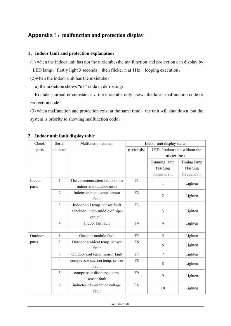
AppendixⅠ:malfunction and protection display
1.Indoor fault and protection explanation
(1) when the indoor unit has not the nixietube,the malfunction and protection can display by
LED lamp:firstly light 3 seconds,then flicker n at 1Hz,looping execution;
(2)when the indoor unit has the nixietube:
a) the nixietube shows “dF” code in defrosting;
b) under normal circumstances,the nixietube only shows the latest malfunction code or
protection code;
(3) when malfunction and protection exist at the same time, the unit will shut down .but the
system is priority to showing malfunction code。
2.Indoor unit fault display table Indoor unit display status
LED(indoor unit without the nixietube)
Check parts
Serial number
Malfunction content nixietube
Running lamp Flashing
frequency n
Timing lampFlashing
frequency n 1 The communication faults in the
indoor and outdoor units F1
1 Lighten
2 Indoor ambient temp. sensor fault
F2 2 Lighten
3
Indoor coil temp. sensor fault (include:inlet、middle of pipe、
outlet)
F3 3 Lighten
4 Indoor fan fault F4 4 Lighten
Indoor parts
1 Outdoor module fault F5 5 Lighten 2 Outdoor ambient temp. sensor
fault F6
6 Lighten
3 Outdoor coil temp. sensor fault F7 7 Lighten 4 compressor suction temp. sensor
fault F8
8 Lighten
5 compressor discharge temp. sensor fault
F9 9 Lighten
Outdoor parts
6 inductor of current or voltage fault
FA 10 Lighten

Page 31 of 58
7 compressor drive abnormal fault FC 11 Lighten 8 Power supply phase lacking or
phase sequence fault FD
12 Lighten
9 Return-air sensor abnormal (include these roads A、B、C、
D)
FE 13 Lighten
10 Others fault FF 14 Lighten 11 Outdoor DC fan fault FH 15 Lighten
3.Indoor unit protection display table
Indoor unit display status LED(indoor unit without the nixietube)
Check parts
Serial number
Protection content nixietube
Running lamp Flashing frequency n
Timing lampFlashing frequency n
1 Evaporator temp. protection
P1 Lighten 1
Indoor parts
1 overheat, over current
protection of inverter module
P2 Lighten 2
2 over current protection P3 Lighten 3 3 Compressor discharging
temp.protection P4 Lighten 4
4 over heat of compressor top protection
P5 Lighten 5
5 suction temp. of compressor protection
P6 Lighten 6
6 power supply overcurrent / overvoltage protection
P7 Lighten 7
7 low presser of gas return protection
P8 Lighten 8
8 high pressure of discharge protection
P9 Lighten 9
9 high temp. of condenser protection
PA Lighten 10
10 high temp. of outdoor ambient protection
PC Lighten 11
Outdoor parts
11 system lacking fluorine or reversing valve protection
PH Lighten 12

Page 32 of 58
12 Other protection PF Lighten 13
AppendixⅡ: display lamp panel
Note:when the system electrifies at first time,all the patterns on display lamp panel and
LED lamp all lighten,and extinguish after 2s.
Display modes of two LED-indicating lamps and double-8-LED
(1) Running lamp: Lightened when starting-up with power on, extinguished when turning
off, flash at the frequency of one time /one second in the mode of anti-cooling air.。
(2) Timing lamp: lightened during timing condition, extinguishing in other conditions.。
(3) Display of the digital tube:
a) The digital tube displays the set temperature of the air conditioner under the normal
condition.;
b) When the user has set the timed turning on or off, the digital tube will display the time of
the timed turning on or off, after the time has been set, it will return back to display the set
temperature after the set time flashes for five seconds.;
c) Only the remaining time is displayed at the time of timed turn on.;
d) Only the “dF” is displayed during defrosting.;
e) The faults or protection codes are displayed at the time of the faults or protection.。
IV、Failure display
LED
running
lamp(flicker
times)
timer
lamp(flicker
times)
Fault content The reason of fault and solution
F1 1 light communication fault 1、Check whether the connection of the outdoor

Page 33 of 58
unit and indoor unit is one to one, otherwise connect the L, N and communication line of the indoor unit and outdoor unit one to one.
2、Measure whether the voltage between the zero line and the communication line is 18V-30AC half-wave signal, check whether the communication circuit on the indoor and outdoor electric control board has been damaged, otherwise replace it.
3、Check whether the LED on the outdoor power board has been on, otherwise replace the electric control board.
4、Check whether the unit is abnormal caused by the external interference, if it is, then find the interfering source, and removes it.
F2 2 light The indoor ambient
temp. sensor fault
1、Check whether the resistance of sensor is normal, otherwise replace it.
2、Check whether the sensor wire is short circuit or open circuit, and whether the plug is well contacted, whether there is welding off or rosin joint on the electric control board, repair it if there is any above.
3、When the 1 and 2 are both normal, then the components or integrated circuit is damaged, the electric control board should be replaced.
F3 3 light
The coil pipe temp.
sensor of indoor unit
fault(include :inlet,
middle, outlet)
1、Check whether the resistance of sensor is normal, otherwise replace it.
2、Check whether the sensor wire is short circuit or open circuit, and whether the plug is well contacted, whether there is welding off or rosin joint on the electric control board, repair it if there is any above.
3、When the 1 and 2 are both normal, then the components or integrated circuit is damaged, the electric control board should be replaced.
F4 4 light indoor fan fault
1、 Check whether the contact of the plug of the motor wire and socket is well, making sure well contact.
2、Check whether the indoor motor has damaged, the motor should be replaced when it is damaged.
3、Check whether the controllable silicon and other components on the electric control

Page 34 of 58
board have damaged, replace the controllable silicon or electric control board when they are damaged.
F5
5
light
module of outdoor unit
fault
1、Check whether the connection of the
compressor is reliable, otherwise connect firmly again.
2、Check whether the fixation between the IPM module and the radiator is firm.
3、 Check whether the compressor is well, otherwise replace it.
4、 Check whether the IPM module is abnormal, otherwise replace it.
F6 6 light The outdoor ambient
temp. sensor fault
1、Check whether the resistance of sensor is normal, otherwise replace it.
2、Check whether the sensor wire is short circuit or open circuit, and whether the plug is well contacted, whether there is welding off or rosin joint on the electric control board, repair it if there is any above.
3、When the 1 and 2 are both normal, then the components or integrated circuit is damaged, the electric control board should be replaced.
F7 7 light The outdoor unit coil
pipe temp. sensor fault
1、Check whether the resistance of sensor is normal, otherwise replace it.
2、Check whether the sensor wire is short circuit or open circuit, and whether the plug is well contacted, whether there is welding off or rosin joint on the electric control board, repair it if there is any above.
3、When the 1 and 2 are both normal, then the components or integrated circuit is damaged, the electric control board should be replaced.
F8 8 light The compressor suction
temp. sensor fault
1、Check whether the resistance of sensor is normal, otherwise replace it.
2、Check whether the sensor wire is short circuit or open circuit, and whether the plug is well contacted, whether there is welding off or rosin joint on the electric control board, repair it if there is any above.
3、When the 1 and 2 are both normal, then the components or integrated circuit is damaged, the electric control board should

Page 35 of 58
be replaced.
F9 9 light
The compressor
discharge temp. sensor
fault
1、Check whether the resistance of sensor is normal, otherwise replace it.
2、Check whether the sensor wire is short circuit or open circuit, and whether the plug is well contacted, whether there is welding off or rosin joint on the electric control board, repair it if there is any above.
3、When the 1 and 2 are both normal, then the components or integrated circuit is damaged, the electric control board should be replaced.
FA 10 light inductor of current or
voltage fault
1、Check whether inductor of current or
voltage have been damaged, they should be
replaced if they are fault.
FC 11 light compressor drive fault
1、Power on again, and check the operation of the compressor is normal.
2、Check whether the connection of the compressor is reliable, otherwise repair.
3、Check whether the components on the electric control board have been damaged, if they are damaged, the components or the electric control board should be replaced.
FE 13 light
gas return sensor
fault(include :
A,B,C,D pipe road)
1、Check whether the resistance of sensor is normal, otherwise replace it.
2、Check whether the sensor wire is short circuit or open circuit, and whether the plug is well contacted, whether there is welding off or rosin joint on the electric control board, repair it if there is any above.
3、 When the 1 and 2 are both normal, then the components or integrated circuit is damaged, the electric control board should be replaced.
FF 14 light other fault
1 check whether the system pressure is normal,
whether to have the broken tube result in the
leakage of refrigerant.
2 check whether the indoor coil temperature
sensor is installed in place.
3 check whether the four-way valve runs
abnormally.
P1
light
1
The evaporator temp.
1、Check whether the filter of indoor unit is too

Page 36 of 58
protection dirty, and it should be cleaned when it is too dirty. 2、Check whether it has barrier around
indoor unit, it should be remove if it
has.
3、Check whether the indoor motor is damaged, it should be replaced motor or electrical control board when it is damaged.
P2 light 2
overheat, over current
protection of inverter
module
1、Check whether the fixation between the IPM module and the radiator is firm.
2、Check whether the compressor is well, otherwise replace it.
3、 Check whether the IPM module is abnormal, otherwise replace it.
P3 light 3
AC input current over
large protection
1、Check whether the ambient temperature exceeds the operation range for the air conditioner
2、Check whether the current detection circuit is abnormal, the electric control should be replaced when it is abnormal.
P4 light 4 The discharge temp. of
compressor protection
1、Check whether the air condition system and pressure are normal.
2、Check whether the sensor, connecting wire of the sensor and the detection circuit are abnormal.
P6 light 6 The suction temp. of
compressor protection
1、 Check whether the air condition system and pressure are normal.
2、 Check whether the sensor, connecting wire of the sensor and the detection circuit are abnormal.
P7 light 7 low or high voltage
protection
1、Check whether the supply voltage is out of rang from 150 to 270V
2、Check the voltage detection circuit of the IPM base board is abnormal, if it is abnormal, the IPM base board or the electric control board should be replaced.
P8 light 8 low presser of gas
return protection
1、Check whether the pressure is normal when the unit is running, if it is abnormal, should detect the leakage and welding、 add refrigerant.
P9 light 9 high pressure of
discharge protection
1、 Check whether the pressure is normal when the unit is running, if it is abnormal, should detect the leakage and welding、 add refrigerant.

Page 37 of 58
PA light 10 The evaporator coil
high temp. protection
1、Check whether the condenser of outdoor unit is too dirty, and it should be cleaned when it is too dirty. 2、 Check whether it is running at bad
condition long time.
3、Check whether senor and wire are normal.
PC light 11 The outdoor ambient
high temp. protection
1、Check the outdoor ambient temperature is too high or there is heat source around the outdoor unit.
2、 Check whether the sensor and sensor wire are normal.
PH light 12
Lack the refrigerant or
reversal valve
protection
1 、 check whether the system pressure is
normal, whether to have the broken tube result
in the leakage of refrigerant.
2、 check whether the reversal valve runs
abnormally.
V、Reference of the fault code and detecting methods for inverter Please note: this operation guidance is for maintenance reference only, it can be different from the units you order. A、F1 (Communication fault) the possible reasons and detecting measures:
1. First, check whether the wires of the indoor and outdoor terminal boards are wrong connection or poor connection.
2. Check whether the alternating current of the outdoor PCB is normal, or whether the fuse is loosened or blew out.
(the input voltage of the outdoor terminal) (the input voltage of the Bridge rectifier)

Page 38 of 58
(the fuse can be gotten through under the normal situation. Change the fuse if it is open circuit.)
3. Check whether the voltage of the DC PN is normal. The normal voltage should be around 300V.
(the output voltage of the Bridge rectifier) (the output voltage of the PN)
4. Check whether the input power cord or the output power cord is mistakenly connected in the
controller board.
5. Check whether the communication voltage between the N and S is normal. Use the AC voltage gear to measure the voltage. If it changes from several volts to scores of volts, it means the communication voltage is normal.
6. Check whether the bridge rectifiers are damaged

Page 39 of 58
(The forward resistance of every diode in the bridge rectifiers should be around 500Ω)
7. Check whether the electrolytic capacitor is convex or burned out.
8. Check whether the IGBT is damaged
(remove one terminal when measuring the output resistance of the bridge rectifiers
(the AC input resistance of the bridge rectifier should be infinite)
Cracking and Convex

Page 40 of 58
; 9. Check whether the relative electronic components are burned out or loose weld by eyeballing.
10. Check whether the external environment exists the source of the strong electromagnetism, which may cause disturb.
11. If the above procedures cannot solve the problem, please change the outdoor whole
set of the electric control boards.
B.F2(Room Temperature sensor fault) F3(Indoor coil exit temperature sensor
fault,Indoor coil entry temperature sensor fault or Indoor coil mid point
temperature sensor fault)
1. Measure the resistance of the temperature sensor and check it referring to the
resistance table. Check if the resistance has a serious deviation to the table.
(the environment temperature is about 32 degrees
centigrade)
2. Check whether the inserter or the wires of the sensor are damage by eyeballing.
3. Check whether the sensor’s circuit in the electronic control board is loss weld
or damaged.
4. If the above procedures cannot solve the problem, please change the indoor electric
board.
C、F4: fault of PG fan motor
1、 Check whether the contacted terminal of the fan motor is loose.
2、 Check whether the startup winding and running winding of the fan motor is broken
(open circuit or short circuit)

Page 41 of 58
3、 Check whether the fan motor or the blade of it is blocked.
4、 Check whether the indoor PCB is faulty (no signal output of the fan motor)
D、F6 fault of the outdoor sensor
1、Measure the resistance of the sensor and check up with the temperature-resistance
table, and see if there is a great departure with the resistance.
2、Check whether the contactor and the circuitry is well
3、Check whether there is loose weld or damage of the sensor circuit part, situation
like rupture which the finger points at in the following picture:
4、 If the above procedures cannot solve the problem, please change the indoor PCB.
rupture which the finger points at

Page 42 of 58
E、FC fault of the outdoor drive and failure of the compressor startup 1、Drive module burns out, that is short circuit between P、U、V、W、N terminal.
(Normal forward resistance between P terminal and U,V,W,N terminal should be 380-450
Ω)
(Normal voltage between U terminal and V,W terminal should be 170-270V)
2、Check whether the U,V,W terminals is contacted well
3、Check whether the compressor winding is burnt out.
(Normal resistance of the three windings should be the same and probably equal to
1Ω)
5、Check whether the compressor is blocked. If blocked, please try to beat the compressor
with rubber stick slightly.
F、dI mode conflict or not allowed We suggest you reset the running mode (cold or heat), and make sure all the indoor units are
running in the same mode. G、 dF: defrost
1、Under the heat mode, it’s a normal display of defrosting. 2、Under other mode except heat, if there is a dF code, perhaps the anti-jamming capacity of the

Page 43 of 58
inductance is too weak which leads to a misinformed faulty code. Please check whether there is a magnetic ring on the connecting pipe of the indoor and outdoor units.
H、 P2:fault of the outdoor inverter module protection
1、Check whether the connection of the compressor is reliable. If not, please make it firmly enough. 2、Check whether the fixation between the IPM module and the radiator is firm. 3、Check whether the compressor is well. If not, please replace it. 4、Check whether the IPM module is normal. If not, please replace it.
I、P3 ac current input of the outdoor unit is too large
1、Check whether the ambient temperature exceeds the operation range of the air conditioner 2、Check whether the current detection circuit is abnormal. The electric control should be replaced if it is abnormal. 3、Check whether the outdoor fan motor is broken or not, following is the test method of ac outdoor motor:
4、 If the above procedures cannot solve the problem, we suggest changing the
inductance.
J、 P4 discharge temperature of the outdoor compressor is too high, the outdoor ambient temperature is too high, temperature switch of compressor shell is breaking, the module is over temperature 1、Check whether the pressure is normal when the unit is running. If abnormal, should detect the
leakage and welding, and then add refrigerant. 2、 Check whether outdoor ambient temp. is too high or too low, when the temp. is
more than -20 degree and less than 55 degree, it can disappear automatically.
3、Communicate interference. Earth wire and communicate wire can’t put in one cable. 4、Check whether temp. switch of compressor is damage, it should be replace if it’s

Page 44 of 58
damaged.
K、 P7 dc generatrix voltage of outdoor unit is abnormal 1、Check whether the power supply voltage is out of rang from 150 to 270V 2.、Check the voltage detection circuit of the IPM base board is abnormal, if abnormal, the IPM base
board or the electric control board should be replaced. L、 P8: gas leakage or fault of the selector valve
1、Check whether the high and low pressure valves have been opened. If not, please open the valves. 2、Check whether the indoor coil pipe temperature sensor is normal. If abnormal, the sensor should
be replaced. 3、Check the system pressure is normal. If abnormal, should detect leakage repairing, welding and
add the refrigerant
4、Check whether the coil resistance of the electric expansion is normal and the valve body is open
completely.
5、Check and listen if the sound of 4-way selector valve is crisp.
The high pressure pipe defrosts, which indicates gas leakage or electric expansion valves is not open completely.

Page 45 of 58
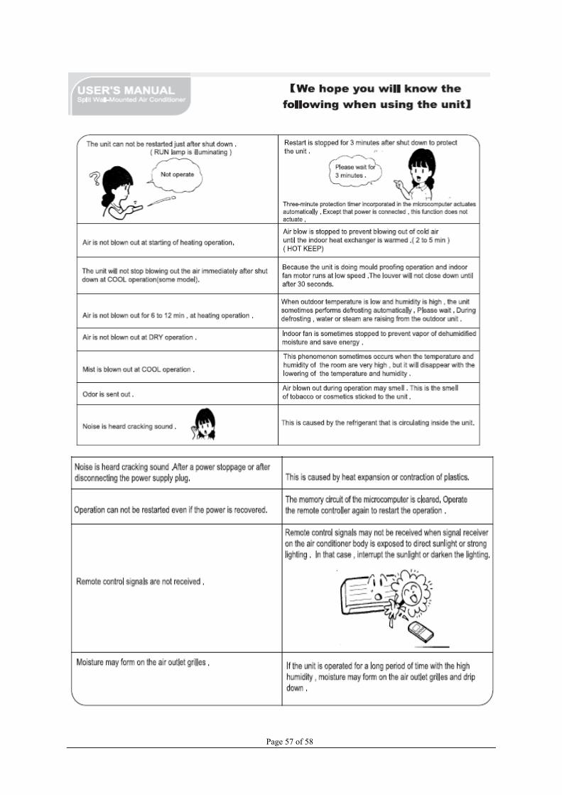
VI .User’s Manual For Split Wall-Mounted Air Conditioner
Please read the user’s manual carefully before using the product
Instructions to users

Page 46 of 58

Page 47 of 58

Page 48 of 58
The name of each part and its function

Page 49 of 58

Page 50 of 58
Indications of unit
Remote controller

Page 51 of 58

Page 52 of 58
Use of remote controller
Operating machine in selected modes

Page 53 of 58

Page 54 of 58
Basic principles and performances
Features of Heating Operations

Page 55 of 58
Methods of maintenance

Page 56 of 58
Page 57 of 58

Page 58 of 58