
DBS3 Cor DBS5 Core
48
PRODUCT INFORMATION DBS36 Core / DBS50 Core THE MULTI-FIT INCREMENTAL ENCODER Inremental encoders
Transcript of DBS3 Cor DBS5 Core

PR
OD
UC
T I
NF
OR
MA
TIO
N
DBS36 Core / DBS50 CoreTHE MULTI-FIT INCREMENTAL ENCODER
Inremental encoders

E n c o d E r s | s I c K 8015321/2020-11-032Subject to change without notice
dBs36 core Incremental encoderS
Product descriptionthe dBS36 core incremental encoder features impressively high mechanical flexibility, excellent technical properties, and a number of variations. a blind hollow shaft with a shaft diameter of up to 8 mm and a face mount flange with 6 mm and 1/4” solid shaft are avail-able. The design with face mount flange offers 2 different flanges with 6 different
mounting hole patterns and a servo groove for mounting with servo clamps. the hollow shaft design has a universal stator coupling that can be used for multiple typical mounting hole circles. all models have compact dimensions and a universal cable connection that allows for cables to run in an axial or radial direction.
at a glance• Universal cable connection• designs with blind hollow shaft or
face mount flange with solid shaft• Face mount flange with 6 mounting
hole patterns and servo groove
• communication interfaces: ttl/rS-422, HTL/push pull, Open Collector
• number of lines from 10 to 2,500 possible
• Temperature range: –20 °C ... +85 °C• Enclosure rating: IP65
Your benefits• the universal cable connection
enables the device to be used in tight spaces and provides cable routing flexibility
• Different flanges and the universal stator coupling provides mounting without adapting the application
• Shafts in metric and US design en-able worldwide use
• The high flexibility of the mechan-ical interface of the encoder and the available accessories allow for the use of a single design in many applications
• long-term and reliable operation thanks to a high enclosure rating, temperature resistance and bearing lifetime
EncodersIncremental encoderSdBs36 core
Subject to change without notice
.
THE MULTIFIT INCREMENTAL ENCODER
additional information
Fields of application . . . . . . . . . . . . . . .3
detailed technical data . . . . . . . . . . . .3
type code . . . . . . . . . . . . . . . . . . . . . . .6
dimensional drawings . . . . . . . . . . . . .8
Attachment specifications . . . . . . . . .10
PIn assignment. . . . . . . . . . . . . . . . . .10
Signal outputs. . . . . . . . . . . . . . . . . . 11
accessories. . . . . . . . . . . . . . . . . . . . 12
- www.sick.com/dBs36_coreFor more information, simply enter the link or scan the QR code and get direct access to technical data, CAD design models, operating instructions, software, application examples, and much more.
ABCDEF
HIJKLMNOPQRST

E n c o d E r s | s I c K8015321/2020-11-03Subject to change without notice
3
Incremental encoderS dBs36 core
Fields of applicationthere are numerous application possibilities for positioning and speed measurement, such as in the textile industry,
propulsion technology, storage and conveyor, packaging ma-chines, printing presses, glass industry, and elevators
detailed technical data
Performance
Pulses per revolution 0 … 2,500
Measuring step 90° electric/pulses per revolution
Measuring step deviation ± 18° / pulses per revolution
Error limits ± 54° / pulses per revolution
duty cycle ≤ 0.5 ± 5 %
Interfaces
communication interface Incremental
communication Interface detail TTL / RS-422HTL / Push pullopen collector(depending on type)
number of signal channels
TTL / RS-422 6-channel
HTL / Push pull 6-channel / 3 channel (depending on type)
open collector 3 channel
Initialization time < 3 ms
output frequency ≤ 300 kHz
4.5 V… 5.5 V, TTL/rs-422
load current ≤ 30 mA
operating current ≤ 50 mA (without load)
4.5 V ... 5.5 V, open collector
load current ≤ 30 mA
operating current ≤ 50 mA (without load)
TTL/rs-422
load current ≤ 30 mA
Power consumption ≤ 0.5 W (without load)
HTL/Push pull
load current ≤ 30 mA
Power consumption ≤ 0.5 W (without load)
open collector
load current ≤ 30 mA
Power consumption ≤ 0.5 W (without load)
ABCDEF
HIJKLMNOPQRST

E n c o d E r s | s I c K 8015321/2020-11-034Subject to change without notice
dBs36 core Incremental encoderS
electrical data
connection type Cable, 8-wire, universal, 0.5 mCable, 8-wire, universal, 1.5 mCable, 8-wire, universal, 3 mCable, 8-wire, universal, 5 mCable, 8-wire, universal, 10 mCable, 5-wire, universal, 0.5 mCable, 5-wire, universal, 1.5 mCable, 5-wire, universal, 3 mCable, 5-wire, universal, 5 mCable, 5-wire, universal, 10 mCable, 8-wire, with male connector, M12, 8-pin, universal, 0.5 mCable, 8-wire, with male connector, M23, 12-pin, universal, 0.5 m 1)
(depending on type)
supply voltage 4.5 ... 5.5 V
7 ... 30 V
7 ... 27 V
4.5 ... 30 V
(depending on type)
reference signal, number 1
reference signal, position 90°, electric, logically gated with A and B
reverse polarity protection l
short-circuit protection of the outputs l 2)
MTTFd: mean time to dangerous failure 600 years (en ISo 13849-1) 3)
1) M23 male connector for central mounting.2) the short-circuit rating is only given if Us and Gnd are connected correctly.3) This product is a standard product and does not constitute a safety component as defined in the Machinery Directive. Calculation based on nominal load of com-
ponents, average ambient temperature 40°C, frequency of use 8760 h/a. All electronic failures are considered hazardous. For more information, see document no. 8015532.
mechanical data
solid shaft Blind hollow shaft
Mechanical design Solid shaft, face mount flange Blind hollow shaft
shaft diameter 1/4”6 mm(depending on type)
6 mm8 mm 1)
(depending on type)
shaft length
Solid shaft, face mount flange 15.5 mm12 mm(depending on type)
–
Weight + 150 g (with connecting cable)
shaft material Stainless steel
Flange material aluminum
Housing material aluminum
Material, cable PVC
start up torque + 0.5 Ncm (+20 °C)
operating torque 0.4 Ncm (+20 °C)
Permissible shaft movement, axial static/dynamic
– ± 0.5 mm / ± 0.2 mm 2)
Permissible shaft movement, radial static/dynamic
– ± 0.3 mm / ± 0.1 mm 2)
ABCDEF
HIJKLMNOPQRST

E n c o d E r s | s I c K8015321/2020-11-03Subject to change without notice
5
Incremental encoderS dBs36 core
solid shaft Blind hollow shaft
Permissible shaft loading radial/axial 40 n (radial) 2)
20 N (axial)–
operating speed 6,000 min-1 3) 6,000 min-1 4)
Maximum operating speed ≤ 8,000 min-1 5)
Moment of inertia of the rotor 0.6 gcm² 0.8 gcm²
Bearing lifetime 2 x 10^9 revolutions
Angular acceleration ≤ 500,000 rad/s²1) Collets for 5 mm and 6 mm and 1/4” as accessories, separate order item.2) Higher values are possible using limited bearing life.3) Allow for self-heating of 3.3 K per 1,000 rpm when designing the operating temperature range.4) Self warming of 4.7 K per 1000 revolutions/min when applying note working temperature range.5) No permanent operation. Decreasing signal quality.
ambient data
EMc According to EN 61000-6-2 and EN 61000-6-3 (class A)
Enclosure rating IP65
Permissible relative humidity 90 % (condensation of the optical scanning not permitted)
operating temperature range
4.5 V ... 5.5 V, TTL, RS-422 –20 °C ... +85 °C, –35 °C ... +95 °C on request
7 V ... 30 V, TTL, RS-422 –20 °C ... +85 °C, –35 °C ... +95 °C on request
7 V ... 30 V, HTL, Push pull –20 °C ... +85 °C, –35 °C ... +95 °C on request
7 V ... 27 V, HTL, Push pull –20 °C ... +70 °C
4.5 V ... 5.5 V, Open Collector –20 °C ... +85 °C, –35 °C ... +95 °C on request
4.5 V ... 30 V, Open Collector –20 °C ... +85 °C, –35 °C ... +95 °C on request
storage temperature range –40 °C ... +100 °C, without package
resistance to shocks 100 g, 6 ms (EN 60068-2-27)
resistance to vibration 20 g, 10 Hz ... 2,000 Hz (EN 60068-2-6)
ABCDEF
HIJKLMNOPQRST

E n c o d E r s | s I c K 8015321/2020-11-036Subject to change without notice
dBs36 core Incremental encoderS
type code
Solid shaft
Typee eco
Mechanical designS 3 Solid shaft, face mount flange, 6 mm x 12 mmS 8 Solid shaft, face mount flange, 1/4” x 15.5 mm
communication interfacea 4.5 V ... 5.5 V, TTL/RS-422c 7 V ... 30 V, TTL/RS-422e 7 V… 30 V, HTL/push pullG 7 V ... 27 V, HTL/push pullP 4.5 V ... 5.5 V, open collectorr 7 V ... 30 V, open collector
connection typeJ Cable, 5-wire, universal, 0.5 m 1)
J Cable, 8-wire, universal, 0.5 m 2)
K Cable, 5-wire, universal, 1.5 m 1)
K Cable, 8-wire, universal, 1.5 m 2)
l Cable, 5-wire, universal, 3 m 1)
l Cable, 8-wire, universal, 3 m 2)
m Cable, 5-wire, universal, 5 m 1)
m Cable, 8-wire, universal, 5 m 2)
n Cable, 5-wire, universal, 10 m 1)
V Cable, 8-wire, universal, 10 m 2)
P Cable, 8-wire, with male connector, M12, 8-pin, universal, 0.5 mQ Cable, 8-wire, with male connector, M23, 12-pin, universal, 0.5 m
Flange design0 Face mount flange, standard hole patterna Face mount flange, hole pattern A 3)
resolution0001 … 2,500 Pulses per revolution 4) 5)
d B S 3 6 -
1) Only for G, P and R communication interface.2) Only for A, C and E communication interface.3) only for mechanical version S3.4) See “Pulses per revolution” table.5) Other pulses upon request.
Pulses per revolution (other pulses upon request)dBs36
010 0250 0600
020 0256 1000
050 0300 1024
0100 0360 1200
0120 0400 2000
0125 0500 2048
0200 0512 2500
ABCDEF
HIJKLMNOPQRST

E n c o d E r s | s I c K8015321/2020-11-03Subject to change without notice
7
Incremental encoderS dBs36 core
Hollow shaft
Typee eco
Mechanical designB a Blind hollow shaft, 6 mmB B Blind hollow shaft, 8 mm 1)
communication interfacea 4.5 V ... 5.5 V, TTL/RS-422c 7 V ... 30 V, TTL/RS-422e 7 V… 30 V, HTL/push pullG 7 V ... 27 V, HTL/push pullP 4.5 V ... 5.5 V, open collectorr 7 V ... 30 V, open collector
connection typeJ Cable, 5-wire, universal, 0.5 m 2)
J Cable, 8-wire, universal, 0.5 m 3)
K Cable, 5-wire, universal, 1.5 m 2)
K Cable, 8-wire, universal, 1.5 m 3)
l Cable, 5-wire, universal, 3 m 2)
l Cable, 8-wire, universal, 3 m 3)
m Cable, 5-wire, universal, 5 m 2)
m Cable, 8-wire, universal, 5 m 3)
n Cable, 5-wire, universal, 10 m 2)
V Cable, 8-wire, universal, 10 m 3)
P Cable, 8-wire, with male connector, M12, 8-pin, universal, 0.5 mQ Cable, 8-wire, with male connector, M23, 12-pin, universal, 0.5 m
Flange design0 Face mount flange, standard hole pattern
resolution0001 … 2,500 Pulses per revolution 4) 5)
d B S 3 6 -
1) Collets for 5 mm and 6 mm and 1/4” as accessories, separate order item.2) Only for G, P and R communication interface.3) Only for A, C and E communication interface.4) See “Pulses per revolution” table.5) Other pulses upon request.
Pulses per revolution (other pulses upon request)dBs36
010 0250 0600
020 0256 1000
050 0300 1024
0100 0360 1200
0120 0400 2000
0125 0500 2048
0200 0512 2500
ABCDEF
HIJKLMNOPQRST

E n c o d E r s | s I c K 8015321/2020-11-038Subject to change without notice
dBs36 core Incremental encoderS
dimensional drawings (dimensions in mm (inch))
Solid shaft, face mount flange, shaft 1/4” x 15.5 mm
Ø 37
(1.4
6)
2.5(0.10)
6(0.24)
2.1(0.08)
Ø 33
.8(1
.33)
Ø 20
f8(0
.79)
Ø 36
.7(1
.44)
Ø 6.
35(0
.25)
-0.0
05-0
.020
10(0.39)
15.5(0.61)
3(0.12)
35.5(1.40)
0.5(0.02)
3x M3 depth 7 mm (0.28)
3x 120° @ 30 mm (1.18) PCD
3x M
3 de
pth
7 m
m (0
.28)
3x 1
20°
@ 2
8 m
m (1
.10)
PCD
4x M3 depth 7 mm (0.28)
4x 90° @ 30 mm (1.18) PCD
Solid shaft, face mount flange, shaft 6 mm x 12 mm, type 0 flange design hole pattern
35.5(1.40)
0.5(0.02)
3(1.12)
2.5(0.10) 2.1
(0.08)
Ø 36
.7(1
.44)
Ø 20
f8(0
.79)
Ø 6
f7(0
.24)
Ø 33
.8(1
.33)
Ø 37
(1.4
6)
5.6
(0.2
2)
12(0.47)
8.5(0.33)
6(0.24)
Ø 44.5(1.75)
3 x 1
20°
4x M3 depth 7 mm (0.28)4x 90° @ 30 mm (1.18) PCD
3x M3 depht 7 mm (0.28)3x 120° @ 28 mm (1.10) PCD
3x M3 depht 7 mm (0.28)3x 120° @ 30 mm (1.18) PCD
ABCDEF
HIJKLMNOPQRST

E n c o d E r s | s I c K8015321/2020-11-03Subject to change without notice
9
Incremental encoderS dBs36 core
Solid shaft, face mount flange, shaft 6 mm x 12 mm, type A flange design hole pattern
35,5
0,53
2,52,1
Ø 36
,7
Ø 20
f8
Ø 6
f7
Ø 33
,8Ø
37
5,6
12
8,5
6
Ø 44,5
3 x 1
20°
3x M3 tiefe 5 mm3x 120° @ 26 mm PCD
4x M3 tiefe 5 mm4x 90° @ 26 mm PCD
2x M3 tiefe 7 mm2x 180° @ 28 mm PCD
Blind hollow shaft, cable outlet
45.4(1.79)
0.5(0.02)
(7.7)(0.30)
1(0.04)
2x M3 set screwHexagon socket screw size 1,5
4x M2.5 screw@ 30 mm (1.18) PCD
3.2
(0.1
3)
20°
Ø 42(1
.65)
Ø 46(1.81)
21.5(0.85)
Ø 8
F7(0
.31)
Ø 37
(1.4
6)
ABCDEF
HIJKLMNOPQRST

E n c o d E r s | s I c K 8015321/2020-11-031 0Subject to change without notice
dBs36 core Incremental encoderS
Attachment specifications
min. 6
max. 21
Ø X–
0.01
50
Encoder
6 mm dBS36e-Ba 2056390Premounted
5 mm
dBS36e-BB
2066991
6 mm 2056390
1/4″ On request
8 mm Not required
PIn assignment
View of M12 / M23 male device connector on cable / housing
Wire colors (cable connection)
Male connector M12, 8-pin
Male connector M23, 12-pin
HTL/oc 3-channel signal
TTL/HTL 6-channel signal
Explanation
Brown 1 6 n.c. a- Signal wire
White 2 5 a a Signal wire
Black 3 1 n.c. B- Signal wire
Pink 4 8 B B Signal wire
Yellow 5 4 n.c. Z- Signal wire
Purple 6 3 Z Z Signal wire
Blue 7 10 Gnd Gnd Ground connection
red 8 12 US US Supply voltage
- - 9 n.c. n.c. not assigned
- - 2 n.c. n.c. not assigned
- - 11 n.c. n.c. not assigned
ABCDEF
HIJKLMNOPQRST

E n c o d E r s | s I c K8015321/2020-11-03Subject to change without notice
1 1
Incremental encoderS dBs36 core
Signal outputsSignal outputs for electrical interfaces TTL and HTL
Measuring step
Cw with view on the encoder shaft in direction “A”, compare dimensional drawing.1 Interfaces G, P, R only for channels A, B, Z.
supply voltage output
4.5 V...5.5 V TTL/RS422
7 V...30 V TTL/RS422
7 V...30 V HTL/Push Pull
7 V...27 V HTL/push pull, 3 channel
4.5 V...5.5 V Open Collector NPN, 3 channel
4.5 V...30 V Open Collector NPN, 3 channel
ABCDEF
HIJKLMNOPQRST

E n c o d E r s | s I c K 8015321/2020-11-031 2Subject to change without notice
dBs36 core Incremental encoderS
accessories
mounting systems
Flanges
Flange plates
Figure Brief description Type Part no.
Flange adapter, adapts face mount flange with 20 mm centering collar to 33 mm servo flange, Aluminum BEF-FA-020-033 2066312
dimensional drawings g page 16
mounting brackets and plates
mounting brackets
Figure Brief description Type Part no.
Mounting bracket for encoder with centering hub 20 mm, including mounting kit for face mount flange, mounting kit for face mount flange included BEF-WF-20 2066393
dimensional drawings g page 16
other mounting accessories
measuring wheels and measuring wheel systems
Figure Brief description Type Part no.
Aluminium measuring wheel with O-ring (NBR70) for 6 mm solid shaft, circumference 200 mm BEF-MR006020R 2055222
Measuring wheel with O-ring (NBR70) for 6 mm solid shaft, circumference 300 mm BeF-mr006030r 2055634
Aluminium measuring wheel with O-ring (NBR70) for 6 mm solid shaft, circumference 500 mm BEF-MR006050R 2055225
Aluminum measuring wheel with cross-knurled surface for 6 mm solid shaft, circum-ference 200 mm BEF-MR06200AK 4084745
Aluminum measuring wheel with smooth polyurethane surface for 6 mm solid shaft, circumference 200 mm BEF-MR06200AP 4084746
Aluminum measuring wheel with ridged polyurethane surface for 6 mm solid shaft, circumference 200 mm BEF-MR06200APG 4084748
Aluminum measuring wheel with studded polyurethane surface for 6 mm solid shaft, circumference 200 mm BEF-MR06200APN 4084747
O-ring for measuring wheels (circumference 200 mm) BEF-OR-053-040 2064061
o-ring for measuring wheels (circumference 300 mm) BEF-OR-083-050 2064076
O-ring for measuring wheels (circumference 500 mm) BEF-OR-145-050 2064074
dimensional drawings g page 16
others
Figure Brief description Type Part no.
Two-sided stator coupling, screw hole diameter 42 to 46 mm, slot width 3.2 mm BeF-dS-dBS36 2066301
dimensional drawings g page 17
ABCDEF
HIJKLMNOPQRST

E n c o d E r s | s I c K8015321/2020-11-03Subject to change without notice
1 3
Incremental encoderS dBs36 core
Shaft adaptation
collets and clamping rings
Figure Brief description Type Part no.
Collet for blind hollow shaft, shaft diameter 5 mm, external diameter 8 mm SPZ-005-AD-A 2066991
Collet for blind hollow shaft, shaft diameter 6 mm, outer diameter 8 mm SPZ-006-dd36-a 2056390
dimensional drawings g page 17
Shaft couplings
Figure Brief description Type Part no.
Bellows coupling, shaft diameter 6 mm / 6 mm, maximum shaft offset: radial ± 0.25 mm, axial ± 0.4 mm, angular +/- 4°; max. speed 10,000 rpm, –30 °C to +120 °C, max. torque 80 Ncm; material: stainless steel bellows, aluminum hub
KUP-0606-B 5312981
Bar coupling, shaft diameter 6 mm / 6 mm, maximum shaft offset: radial ± 0.3 mm, axial ± 0.2 mm, angle ± 3°; max. speed 10,000 rpm, –10° to +80 °C, max. torque 80 Ncm; material: fiber-glass reinforced polyamide, aluminum hub
KUP-0606-S 2056406
Bar coupling, shaft diameter 6 mm /8 mm, maximum shaft offset radial ± 0.3 mm, axial ± 0.2 mm, angle ± 3°, max. speed 10,000 rpm, torsion spring rigidity 38 Nm/wheel; material: fiber-glass reinforced polyamide, aluminum hub
KUP-0608-S 5314179
Bellows coupling, shaft diameter 6 mm / 10 mm, maximum shaft offset: radial ± 0.25 mm, axial ± 0.4 mm, angular +/- 4°; max. speed 10,000 rpm, –30 °C to +120 °C, max. torque 80 Ncm; material: stainless steel bellows, aluminum hub
KUP-0610-B 5312982
Double loop coupling, shaft diameter 6 mm / 10 mm, max. shaft offset: radially +/- 2,5 mm, axially +/-3 mm, angle +/- 10 degrees;max. speed 3.000 rpm, –30 to +80 degrees Celsius, torsional spring stiffness of 25 Nm/rad
KUP-0610-d 5326697
Spring washer coupling, shaft diameter 6 mm / 10 mm, Maximum shaft offset: radial +/- 0.3 mm, axial +/- 0.4 mm, angular +/- 2.5°; max. speed 12,000 rpm, –10° to +80 °C, max. torque 60 Ncm; material: aluminum flange, glass fiber-reinforced polyamide membrane and hardened steel coupling pin
KUP-0610-F 5312985
Bar coupling, shaft diameter 6 mm / 10 mm, max. shaft offset: radial ± 0,3 mm, axial ± 0,3 mm, angular ± 3°; max. speed 10.000 rpm, –10° to +80 °C, max. torque: 80 Ncm, material: fiber-glass reinforced polyamide, aluminum hub
KUP-0610-S 2056407
dimensional drawings g page 17
connection systems
Plug connectors and cables
cables (ready to assemble)
Figure Brief description Type Part no.
Head A: cableHead B: Flying leadsCable: SSI, Incremental, HIPERFACE®, PUR, halogen-free, shielded, 4 x 2 x 0.15 mm², 5.6 mm
LTG-2308-MWENC 6027529
Head A: cableHead B: Flying leadsCable: SSI, PUR, shielded, 4 x 2 x 0.25 mm2 + 2 x 0.5 mm2 + 1 x 0.14 mm², 7.5 mm
LTG-2411-MW 6027530
Head A: cableHead B: Flying leadsCable: SSI, PUR, halogen-free, shielded, 4 x 2 x 0.25 mm² + 2 x 0.5 mm² + 2 x 0.14 mm², 7.8 mm
LTG-2512-MW 6027531
Head A: cableHead B: Flying leadsCable: SSI, TTL, HTL, PUR, halogen-free, shielded, 4 x 2 x 0.25 mm² + 2 x 0.5 mm² + 2 x 0.14 mm², 7.8 mm, UV and saltwater-resistant
LTG-2612-MW 6028516
ABCDEF
HIJKLMNOPQRST

E n c o d E r s | s I c K 8015321/2020-11-031 4Subject to change without notice
dBs36 core Incremental encoderS
connecting cables
Figure Brief description Length of cable Type Part no.
Head A: female connector, M12, 5-pin, angled, A-codedHead B: Flying leadsCable: Sensor/actuator cable, Power, PUR, halogen-free, shielded, 5 x 0.34 mm², 5.3 mm
1.5 m DOL-1205-W1M5ACSCO 6049455
Head A: female connector, M12, 8-pin, straightHead B: Flying leadsCable: PUR, halogen-free, shielded, 4 x 2 x 0.25 mm², 7 mm
2 m DOL-1208-G02MAC1 6032866
5 m DOL-1208-G05MAC1 6032867
10 m DOL-1208-G10MAC1 6032868
20 m DOL-1208-G20MAC1 6032869
25 m DOL-1208-G25MAC1 6067859
Head A: female connector, M23, 12-pin, straightHead B: Flying leadsCable: Incremental, PUR, shielded, 4 x 2 x 0.25 mm2 + 2 x 0.5 mm2 + 1 x 0.14 mm², 7.5 mm
2 m DOL-2312-G02MLA3 2030682
Head A: female connector, M23, 12-pin, straightHead B: Flying leadsCable: Incremental, PUR, halogen-free, shielded, 4 x 2 x 0.25 mm² + 2 x 0.5 mm² + 2 x 0.14 mm², 7.8 mm
3 m DOL-2312-G03M-ma3 2029213
5 m DOL-2312-G05M-ma3 2029214
Head A: female connector, M23, 12-pin, straightHead B: Flying leadsCable: Incremental, PUR, shielded, 4 x 2 x 0.25 mm2 + 2 x 0.5 mm2 + 1 x 0.14 mm², 7.5 mm
7 m DOL-2312-G07MLA3 2030685
10 m DOL-2312-G10MLA3 2030688
Head A: female connector, M23, 12-pin, straightHead B: Flying leadsCable: Incremental, PUR, halogen-free, shielded, 4 x 2 x 0.25 mm² + 2 x 0.5 mm² + 2 x 0.14 mm², 7.8 mm
10 m DOL-2312-G10MMA3 2029215
Head A: female connector, M23, 12-pin, straightHead B: Flying leadsCable: Incremental, PUR, shielded, 4 x 2 x 0.25 mm2 + 2 x 0.5 mm2 + 1 x 0.14 mm², 7.5 mm
15 m DOL-2312-G15MLA3 2030692
Head A: female connector, M23, 12-pin, straightHead B: Flying leadsCable: Incremental, PUR, halogen-free, shielded, 4 x 2 x 0.25 mm² + 2 x 0.5 mm² + 2 x 0.14 mm², 7.8 mm
1.5 m DOL-2312-G1M5MA3 2029212
Head A: female connector, M23, 12-pin, straightHead B: Flying leadsCable: Incremental, PUR, shielded, 4 x 2 x 0.25 mm2 + 2 x 0.5 mm2 + 1 x 0.14 mm², 7.5 mm
20 m DOL-2312-G20MLA3 2030695
Head A: female connector, M23, 12-pin, straightHead B: Flying leadsCable: Incremental, PUR, halogen-free, shielded, 4 x 2 x 0.25 mm² + 2 x 0.5 mm² + 2 x 0.14 mm², 7.8 mm
20 m DOL-2312-G20M-ma3 2029216
ABCDEF
HIJKLMNOPQRST

E n c o d E r s | s I c K8015321/2020-11-03Subject to change without notice
1 5
Incremental encoderS dBs36 core
Figure Brief description Length of cable Type Part no.
Head A: female connector, M23, 12-pin, straightHead B: Flying leadsCable: Incremental, PUR, shielded, 4 x 2 x 0.25 mm2 + 2 x 0.5 mm2 + 1 x 0.14 mm², 7.5 mm
25 m DOL-2312-G25MLA3 2030699
30 m DOL-2312-G30MLA3 2030702
Head A: female connector, M23, 12-pin, straightHead B: Flying leadsCable: Incremental, PUR, halogen-free, shielded, 4 x 2 x 0.25 mm² + 2 x 0.5 mm² + 2 x 0.14 mm², 7.8 mm
30 m DOL-2312-G30M-ma3 2029217
Head A: female connector, M23, 12-pin, straightHead B: male connector, M23, 12-pin, straightCable: Incremental, PUR, halogen-free, shielded, 4 x 2 x 0.25 mm² + 2 x 0.5 mm² + 2 x 0.14 mm², 7.8 mm
3 m DSL-M2312-G03M-ma3 2118590
5 m DSL-M2312-G05M-ma3 2118591
Head A: female connector, M23, 12-pin, straightHead B: male connector, M23, 12-pin, straightCable: Incremental, PUR, halogen-free, shielded, 4 x 2 x 0.25 mm² + 2 x 0.5 mm² + 2 x 0.14 mm², Ø 7.8 mm
1.5 m DSL-M2312-G1M-5MA3 2118589
Head A: female connector, M23, 12-pin, straightHead B: male connector, M12, 12-pin, straightCable: Incremental, PUR, halogen-free, shielded, 4 x 2 x 0.25 mm² + 2 x 0.5 mm² + 2 x 0.14 mm², 7.8 mm
30 m DSL-M2312-G30M-ma3 2118592
dimensional drawings g page 18
Field-attachable connectors
Figure Brief description Type Part no.
Head A: female connector, M12, 8-pin, straight, A-codedHead B: -Cable: Incremental, SSI, shielded, CAT5, CAT5e
DOS-1208-GA01 6045001
Head A: female connector, M23, 12-pin, straightHead B: -Cable: HIPERFACE®, SSI, Incremental, shielded
DOS-2312-G 6027538
DOS-2312-G02 2077057
Head A: female connector, M23, 12-pin, angledHead B: -Cable: HIPERFACE®, SSI, Incremental, shielded
DOS-2312-W01 2072580
Head A: male connector, M12, 8-pin, straight, A-codedHead B: -Cable: Incremental, shielded, CAT5, CAT5e
STE-1208-GA01 6044892
Head A: male connector, M23, 12-pin, straightHead B: -Cable: HIPERFACE®, SSI, Incremental, RS-422, shielded
STE-2312-G 6027537
Head A: male connector, M23, 12-pin, straightHead B: -Cable: HIPERFACE®, SSI, Incremental, shielded
STE-2312-G01 2077273
STE-2312-GX 6028548
dimensional drawings g page 18
ABCDEF
HIJKLMNOPQRST

E n c o d E r s | s I c K 8015321/2020-11-031 6Subject to change without notice
dBs36 core Incremental encoderS
dimensional drawings for accessories (dimensions in mm (inch))
FlangesBEF-FA-020-033
Ø 28
120°
0,03 A
A 2+0,1
3
Ø 33–0,025 h7
Ø 20+0,005+0,015
0,3 x 45°5
Ø 3,
2±0,
1
mounting brackets and platesBEF-WF-20
3 x 120°
Ø 30
±0.0
5(1
.18)
20±0
.1(0
.79)
65 (2.56)55±0.1 (2.17)
3 x
2(0
.08)
3 x Ø 3.4(0.13)
3 x 90°
Ø 20
+0.1
(0.7
9)+0.2
45 (1
.77)
70 (2
.76)
4 x Ø 4.5(0.18)
5(0
.20)
22(0.87)
50 (1.97)
other mounting accessoriesBEF-MR006020R
Ø 63
.66
(2.5
1)
Ø XH
7
M5
17 (0.67)
8 (0.31)
4 (0.16)
BeF-mr006030r
Ø 95
.7 (3
.77) Ø
XH7
M5
17 (0.67)
9 (0.35)
5 (0.20)
BEF-MR006050R
Ø 15
9.2
(7.6
8) Ø XH
7
M5
5 (0.20)
9 (0.35)17 (0.67)
ABCDEF
HIJKLMNOPQRST

E n c o d E r s | s I c K8015321/2020-11-03Subject to change without notice
1 7
Incremental encoderS dBs36 core
BEF-MR06200AK BEF-MR06200AP BEF-MR06200APG BEF-MR06200APN
BeF-dS-dBS36
Ø 24
(0.9
4)
35.9
(1.4
1)
4x Ø 2.6 (4x 0.10)4x 90° @ Ø 30 (1.18) PCD
7.9 (0.31)
Ø 36 (1.42)
2x 3
.2 (0
.13)
7.9 (0.31)
0.5 (0.02)
0.3 ±0.02(0.02)
0.5 (0.02)
42 (1
.65)
46 (1
.81)
21.8
(0.8
6)10°
10°
Shaft adaptationSPZ-005-AD-A
0.02 A
A
1(0.04)
Ø 5 F7(0.24)
Ø 8 h7(0.31)
21.5 (0.85)
SPZ-006-dd36-a
0.02 A
A
1(0.04)
Ø 6 F7(0.24)
Ø 8 h7(0.31)
21.5 (0.85)
ABCDEF
HIJKLMNOPQRST

E n c o d E r s | s I c K 8015321/2020-11-031 8Subject to change without notice
dBs36 core Incremental encoderS
KUP-06xx-B
Cheese-head screwM2.5 x 8, DIN 912 A2
21±1 (0.83) 29±1 (1.14)Ø
d1 H
8
Ø d2
H8
KUP-06xx-S
22 (0.87) 24 (0.94)
Ø d1
H8
Ø d2
H8
KUP-0608-S
EF8
KUP-0610-d
Ø d1
H8
Ø d2
H8
35±2 (1.38)120°
Ø 38±1 (1.50)
KUP-0610-F
Ø d2
H8
Ø d1
H8
22 (0.87)
Ø 30
(1.1
8)
Plug connectors and cablesDOL-1205-W1M5ACSCO
43
2 1
5
Ø 14.8(0.58)
M12
28 (1.1
0)
Ø 12
(0.4
7)
36.3(1.43)
female connector M 12 x 1, angled, screened
1 Brown2 White3 Blue4 Black5 Gray
DOL-1208-GxxMAC1
All dimensions in mm (inch)
1/brn2/wht
3/blk
4/pnk5/yel
6/vio
7/blu
8/red
ABCDEF
HIJKLMNOPQRST

E n c o d E r s | s I c K8015321/2020-11-03Subject to change without notice
1 9
Incremental encoderS dBs36 core
DOL-2312-G02MLA3
1 Black2 Gray3 Purple4 Yellow5 White6 Brown8 Pink9 Screenß Blueà Greená red
DOL-2312-G03MMA3
1 Black2 Gray3 Purple4 Yellow5 White6 Brown8 Pink9 Screenß Blueà Greená red
DOL-2312-G05MMA3
1 Black2 Gray3 Purple4 Yellow5 White6 Brown8 Pink9 Screenß Blueà Greená red
DOL-2312-G07MLA3
1 Black2 Gray3 Purple4 Yellow5 White6 Brown8 Pink9 Screenß Blueà Greená red
ABCDEF
HIJKLMNOPQRST

E n c o d E r s | s I c K 8015321/2020-11-032 0Subject to change without notice
dBs36 core Incremental encoderS
DOL-2312-G10MLA3
1 Black2 Gray3 Purple4 Yellow5 White6 Brown8 Pink9 Screenß Blueà Greená red
DOL-2312-G10MMA3
1 Black2 Gray3 Purple4 Yellow5 White6 Brown8 Pink9 Screenß Blueà Greená red
DOL-2312-G15MLA3
1 Black2 Gray3 Purple4 Yellow5 White6 Brown8 Pink9 Screenß Blueà Greená red
DOL-2312-G1M5MA3
1 Black2 Gray3 Purple4 Yellow5 White6 Brown8 Pink9 Screenß Blueà Greená red
ABCDEF
HIJKLMNOPQRST

E n c o d E r s | s I c K8015321/2020-11-03Subject to change without notice
2 1
Incremental encoderS dBs36 core
DOL-2312-G20MLA3
1 Black2 Gray3 Purple4 Yellow5 White6 Brown8 Pink9 Screenß Blueà Greená red
DOL-2312-G20MMA3
1 Black2 Gray3 Purple4 Yellow5 White6 Brown8 Pink9 Screenß Blueà Greená red
DOL-2312-G25MLA3
1 Black2 Gray3 Purple4 Yellow5 White6 Brown8 Pink9 Screenß Blueà Greená red
DOL-2312-G30MLA3
1 Black2 Gray3 Purple4 Yellow5 White6 Brown8 Pink9 Screenß Blueà Greená red
ABCDEF
HIJKLMNOPQRST

E n c o d E r s | s I c K 8015321/2020-11-032 2Subject to change without notice
dBs36 core Incremental encoderS
DOL-2312-G30MMA3
1 Black2 Gray3 Purple4 Yellow5 White6 Brown8 Pink9 Screenß Blueà Greená red
DOL-2312-G30MMA3
1
1
2
L ±20 (0.79)
1 Screen, folded2 length of cable
DOS-1208-GA01 DOS-2312-G
1 Blue2 White3 Yellow4 Gray5 Green6 Pink7 Black8 red9 orangeß Brownà Purpleá orange/black
ABCDEF
HIJKLMNOPQRST

E n c o d E r s | s I c K8015321/2020-11-03Subject to change without notice
2 3
Incremental encoderS dBs36 core
DOS-2312-G02
1
210127
8 9
11 365 4
64.7(2.55)
Ø 27
.2(1
.02)
Plug insert 12 pin
(plug-in face)
SW 24SW 24
DOS-2312-W01
EE 11
2233
445566
77
88 99
1100
1111
1122
Contact arrangementMating view
Main dimensionsPlug
81 (3.19)
58 (2
.28)
SW 25
Ø 26 (1.02)
Rotating area tothe left 124°
Rotating area tothe right 200°
SW 27
Ø 27
.2 (1
.07)
STE-1208-GA01 STE-2312-G
STE-2312-G01
8
712102
1 9
11 634 5
66.7(2.63)
Ø 26
.5(1
.04) M
23 x
1
Pin insert 12 pin
(plug-in face)
SW 24SW 24
ABCDEF
HIJKLMNOPQRST

E n c o d E r s | s I c K 8015321/2020-11-032 4Subject to change without notice
dBs36 core Incremental encoderS
STE-2312-GX
110
2
3
411 5
6
12
7
89
1 x
M23
Max. 9 (0.35) 4
57 (2.24)
31 (1.22)
3.5(0.14)
1.5
x M
25
1
2
3
528 (1.10)
P
1 Fixed stop position2 Vibration protection3 Fixing nut SW304 Max. wall thickness5 SW23
ABCDEF
HIJKLMNOPQRST

E n c o d E r s | s I c K8015321/2020-11-03Subject to change without notice
2 5
noteS
ABCDEF
HIJKLMNOPQRST

8015321/2020-11-032 6Subject to change without notice
E N C O D E R S | S I C K
DBS50 Core INCREMENTAL ENCODERS
Product descriptionThe DBS50 Core incremental encoder features impressively high mechanical flexibility, excellent technical proper-ties, and a number of variations. The DBS50E has a 50 mm diameter face mount flange and an 8 mm diameter solid shaft. The housing, which mea-sures 37 mm in diameter and less than 36 mm in length, is extremely compact
and saves valuable installation space. The DBS50E offers a comprehensive range of mounting options thanks to its numerous mounting hole patterns, servo clamps, servo grooves, and triangular servo clamps. The encoder has com-pact dimensions and a universal cable connection that allows for cables to run in an axial or radial direction.
At a glance• Universal cable connection• Face mount flange with 8 mm solid
shaft• Face mount flange with 2 mounting
hole patterns, servo clamps with ser-vo grooves or triangular servo clamps
• Communication interfaces: TTL/RS-422, HTL/push pull, Open Collector
• Number of lines from 10 to 2,500 possible
• Temperature range: –20 °C ... +85 °C• Enclosure rating: IP65
Your benefits• The universal cable connection
enables the device to be used in tight spaces and provides cable routing flexibility
• The different flanges allow the device to be mounted with servo clamps, or mounted at the front or rear side. This enables the device to be replaced without modifying the application
• The high flexibility of the mechan-ical interface of the encoder and the available accessories allow for the use of a single design in many applications
• The compact housing diameter saves valuable space
• Long-term and reliable operation thanks to a high enclosure rating, temperature resistance and bearing lifetime
DBS50 Core
THE MULTIFIT INCREMENTAL ENCODER
Additional information
Fields of application . . . . . . . . . . . . . .27
Detailed technical data . . . . . . . . . . .27
Type code . . . . . . . . . . . . . . . . . . . . . 30
Dimensional drawings . . . . . . . . . . . .31
PIN assignment. . . . . . . . . . . . . . . . . 32
Signal outputs. . . . . . . . . . . . . . . . . . 33
Accessories . . . . . . . . . . . . . . . . . . . . 34
- www.sick.com/DBS50_CoreFor more information, simply enter the link or scan the QR code and get direct access to technical data, CAD design models, operating instructions, software, application examples, and much more.
ABCDEF
HIJKLMNOPQRST

8015321/2020-11-03 2 7Subject to change without notice
E N C O D E R S | S I C K
INCREMENTAL ENCODERS DBS50 Core
Fields of applicationThere are numerous application possibilities for positioning and speed measurement, such as in the textile industry,
propulsion technology, storage and conveyor, packaging ma-chines, printing presses, glass industry, and elevators
Detailed technical data
Performance
Pulses per revolution 0 … 2,500
Measuring step 90° electric/pulses per revolution
Measuring step deviation ± 18° / pulses per revolution
Error limits ± 54° / pulses per revolution
Duty cycle ≤ 0.5 ± 5 %
Interfaces
Communication interface Incremental
Communication Interface detail TTL / RS-422HTL / Push pullOpen Collector(depending on type)
Number of signal channels
TTL / RS-422 6-channel
HTL / Push pull 6-channel / 3 channel (depending on type)
Open Collector 3 channel
Initialization time < 3 ms
Output frequency ≤ 300 kHz
4.5 V… 5.5 V, TTL/RS-422
Load current ≤ 30 mA
Operating current ≤ 50 mA (without load)
4.5 V ... 5.5 V, Open Collector
Load current ≤ 30 mA
Operating current ≤ 50 mA (without load)
TTL/RS-422
Load current ≤ 30 mA
Power consumption < 0.5 W (without load)
HTL/Push pull
Load current ≤ 30 mA
Power consumption < 0.5 W (without load)
Open Collector
Load current ≤ 30 mA
Power consumption < 0.5 W (without load)
ABCDEF
HIJKLMNOPQRST

8015321/2020-11-032 8Subject to change without notice
E N C O D E R S | S I C K
DBS50 Core INCREMENTAL ENCODERS
Electrical data
Connection type Cable, 8-wire, universal, 0.5 mCable, 8-wire, universal, 1.5 mCable, 8-wire, universal, 3 mCable, 8-wire, universal, 5 mCable, 8-wire, universal, 10 mCable, 5-wire, universal, 0.5 mCable, 5-wire, universal, 1.5 mCable, 5-wire, universal, 3 mCable, 5-wire, universal, 5 mCable, 5-wire, universal, 10 mCable, 8-wire, with male connector, M12, 8-pin, universal, 0.5 mCable, 8-wire, with male connector, M23, 12-pin, universal, 0.5 m 1)
(depending on type)
Supply voltage 4.5 ... 5.5 V
7 ... 30 V
7 ... 27 V
4.5 ... 30 V
(depending on type)
Reference signal, number 1
Reference signal, position 90°, electric, logically gated with A and B
Reverse polarity protection l
Short-circuit protection of the outputs l 2)
MTTFd: mean time to dangerous failure 600 years (EN ISO 13849-1) 3)
1) M23 male connector for central mounting.2) The short-circuit rating is only given if Us and GND are connected correctly.3) This product is a standard product and does not constitute a safety component as defined in the Machinery Directive. Calculation based on nominal load of com-
ponents, average ambient temperature 40°C, frequency of use 8760 h/a. All electronic failures are considered hazardous. For more information, see document no. 8015532.
Mechanical data
Mechanical design Solid shaft, face mount flangeSolid shaft, face mount flange 3xM4(depending on type)
Shaft diameter 8 mm
Shaft length
Solid shaft, face mount flange 15.5 mm
Solid shaft, face mount flange 3xM4 13 mm
Weight + 180 g (with connecting cable)
Shaft material Stainless steel
Flange material Aluminum
Housing material Aluminum
Material, cable PVC
Start up torque + 0.9 Ncm (+20 °C)
Operating torque 0.6 Ncm (+20 °C)
Permissible shaft loading radial/axial 30 N (axial)50 N (radial)
Operating speed 6,000 min-1 1)
Maximum operating speed 8,000 min-1 2)
Moment of inertia of the rotor 0.65 gcm²
ABCDEF
HIJKLMNOPQRST

8015321/2020-11-03 2 9Subject to change without notice
E N C O D E R S | S I C K
INCREMENTAL ENCODERS DBS50 Core
Bearing lifetime 2 x 10^9 revolutions
Angular acceleration ≤ 500,000 rad/s²1) Allow for self-heating of 3.3 K per 1,000 rpm when designing the operating temperature range.2) No permanent operation. Decreasing signal quality.
Ambient data
EMC According to EN 61000-6-2 and EN 61000-6-3 (class A)
Enclosure rating IP65
Permissible relative humidity 90 % (condensation of the optical scanning not permitted)
Operating temperature range
4.5 V ... 5.5 V, TTL, RS-422 –20 °C ... +85 °C, –35 °C ... +95 °C on request
7 V ... 30 V, TTL, RS-422 –20 °C ... +85 °C, –35 °C ... +95 °C on request
7 V ... 30 V, HTL, Push pull –20 °C ... +85 °C, –35 °C ... +95 °C on request
7 V ... 27 V, HTL, Push pull –20 °C ... +70 °C
4.5 V ... 5.5 V, Open Collector –20 °C ... +85 °C, –35 °C ... +95 °C on request
4.5 V ... 30 V, Open Collector –20 °C ... +85 °C, –35 °C ... +95 °C on request
Storage temperature range –40 °C ... +100 °C, without package
Resistance to shocks 100 g, 6 ms (EN 60068-2-27)
Resistance to vibration 20 g, 10 Hz ... 2,000 Hz (EN 60068-2-6)
ABCDEF
HIJKLMNOPQRST

8015321/2020-11-033 0Subject to change without notice
E N C O D E R S | S I C K
DBS50 Core INCREMENTAL ENCODERS
Type code
TypeE Eco
Mechanical designS 5 Solid shaft, face mount flange, 8 mm x 15.5 mmS K Solid shaft, face mount flange 3xM4, 8 mm x 13 mm
Communication interfaceA 4.5 V ... 5.5 V, TTL/RS-422C 7 V ... 30 V, TTL/RS-422E 7 V ... 30 V, HTL/push pullG 7 V ... 27 V, HTL/push pullP 4.5 V ... 5.5 V, open collectorR 7 V ... 30 V, open collector
Connection typeJ Cable, 5-wire, universal, 0.5 m 1)
J Cable, 8-wire, universal, 0.5 m 2)
K Cable, 5-wire, universal, 1.5 m 1)
K Cable, 8-wire, universal, 1.5 m 2)
L Cable, 5-wire, universal, 3 m 1)
L Cable, 8-wire, universal, 3 m 2)
M Cable, 5-wire, universal, 5 m 1)
M Cable, 8-wire, universal, 5 m 2)
N Cable, 5-wire, universal, 5 m 1)
N Cable, 8-wire, universal, 5 m 2)
P Cable, 8-wire, with male connector, M12, 8-pin, universal, 0.5 mQ Cable, 8-wire, with male connector, M23, 12-pin, universal, 0.5 m
Stator coupling0 Face mount flange, standard hole pattern
Resolution0001 ... 2,500 Pulses per revolution 3) 4)
D B S 5 0 -
1) Only for G, P and R communication interface.2) Only for A, C and E communication interface.3) See “Pulses per revolution” table.4) Other pulses upon request.
Pulses per revolution (other pulses upon request)DBS50E
0010 0250 0600
0020 0256 1000
0050 0300 1024
0100 0360 1200
0120 0400 2000
0125 0500 2048
0200 0512 2500
ABCDEF
HIJKLMNOPQRST

8015321/2020-11-03 3 1Subject to change without notice
E N C O D E R S | S I C K
INCREMENTAL ENCODERS DBS50 Core
Dimensional drawings (Dimensions in mm (inch))
Face mount flange
35.5(1.40)
0.5(0.02)
4.5(0.18)
Ø 45
.5(1
.79)
Ø 50
(1.9
7)
Ø 30
f8(1
.18)
7.5
(0.3
0)
2.5(0.10) 6
(0.24)
Ø 8
f7(0
.31)
15.5(0.61)
Ø 37
(1.4
6)
10(0.39)
Ø 58(2.28)
3 x M4 (6-depth)
3 x 120° @ 40 mm (1.57) PCD3 x M
3 (6-depth)
3 x 120° @
40 mm (1
.57) PCD
Face mount flange 3xM4
Ø 50 (1.97) 37.2 (1.46)
8 (0.31)
8 (0.31) 13 (0.51)
4 (0.16)Ø 33.5 (1.32)
3x M4
-0.0
1Ø
8 (0
.31)
f7 -0
.03
-0.0
2Ø
25 (0
.98)
f7 -0
.04
Ø 40
(1.5
7)
Ø 37
(1.4
6)
7.5 (0.30)
R 20(0.79)
3x 4.2 (0.17)3x 8 (0.31)
27.5 (1.08)
3x 30°
3x 120°
ABCDEF
HIJKLMNOPQRST

8015321/2020-11-033 2Subject to change without notice
E N C O D E R S | S I C K
DBS50 Core INCREMENTAL ENCODERS
PIN assignment
View of M12 / M23 male device connector on cable / housing
Wire colors (cable connection)
Male connector M12, 8-pin
Male connector M23, 12-pin
HTL/OC 3-channel signal
TTL/HTL 6-channel signal
Explanation
Brown 1 6 N.C. A- Signal wire
White 2 5 A A Signal wire
Black 3 1 N.C. B- Signal wire
Pink 4 8 B B Signal wire
Yellow 5 4 N.C. Z- Signal wire
Purple 6 3 Z Z Signal wire
Blue 7 10 GND GND Ground connection
Red 8 12 US US Supply voltage
- - 9 N.C. N.C. Not assigned
- - 2 N.C. N.C. Not assigned
- - 11 N.C. N.C. Not assigned
- - 7 N.C. N.C. Not assigned
Screen Screen Screen Screen Screen Screen connected to encoder housing
ABCDEF
HIJKLMNOPQRST

8015321/2020-11-03 3 3Subject to change without notice
E N C O D E R S | S I C K
INCREMENTAL ENCODERS DBS50 Core
Signal outputsSignal outputs for electrical interfaces TTL and HTL
Measuring step
Cw with view on the encoder shaft in direction “A”, compare dimensional drawing.1 Interfaces G, P, R only for channels A, B, Z.
Supply voltage Output
4.5 V...5.5 V TTL/RS422
7 V...30 V TTL/RS422
7 V...30 V HTL/Push Pull
7 V...27 V HTL/push pull, 3 channel
4.5 V...5.5 V Open Collector NPN, 3 channel
4.5 V...30 V Open Collector NPN, 3 channel
ABCDEF
HIJKLMNOPQRST

8015321/2020-11-033 4Subject to change without notice
E N C O D E R S | S I C K
DBS50 Core INCREMENTAL ENCODERS
Accessories
Mounting systems
Flanges
Flange plates
Figure Brief description Type Part no.
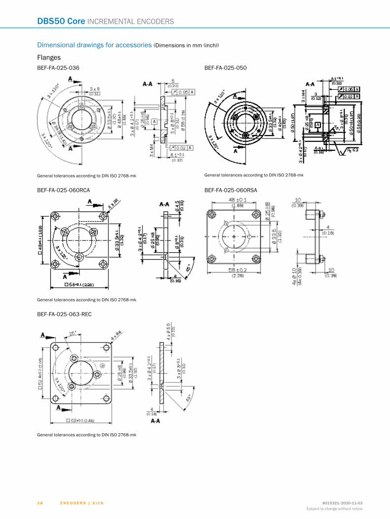
Flange adapter, adaption of 25 mm spigot face mount flange to 60s face mount flange with 36 mm centering collar, Aluminum BEF-FA-025-036 2034226
Flange adapter, adaption of 25 mm spigot face mount flange to 50 mm servo flange, Aluminum BEF-FA-025-050 2032622
Flange adapter, adaption of 25 mm spigot face mount flange to 60 mm square installa-tion plate, Aluminum BEF-FA-025-060RCA 2032623
Flange adapter, adaption of 25 mm spigot face mount flange to 60 mm square installa-tion plate with shock-absorber, Aluminum BEF-FA-025-060RSA 2032624
Flange adapter, adapts face mount flange with 25 mm centering collar to 63 mm square mounting plate, Aluminum
BEF-FA-025-063-REC 2033631
Dimensional drawings g page 38
Mounting brackets and plates
Mounting brackets
Figure Brief description Type Part no.
Mounting brackets for encoders with a centering spigot 25 mm, mounting kit for face mount flange included BEF-WF-25 2032621
Dimensional drawings g page 39
Other mounting accessories
Measuring wheels and measuring wheel systems
Figure Brief description Type Part no.
Aluminum measuring wheel with cross-knurled surface for 8 mm solid shaft, circum-ference 200 mm BEF-MR08200AK 4084741
Aluminum measuring wheel with smooth polyurethane surface for 8 mm solid shaft, circumference 200 mm BEF-MR08200AP 4084742
Aluminum measuring wheel, ground PUR ring covering for greater circumference accu-racy, spare parts package consisting of 10 measuring wheels, circumference 200 mm +/-0.2 mm; for shaft with Ø 8 mm
BEF-MR08200APA 2109902
Aluminum measuring wheel with ridged polyurethane surface for 8 mm solid shaft, circumference 200 mm BEF-MR08200APG 4084744
Aluminum measuring wheel with studded polyurethane surface for 8 mm solid shaft, circumference 200 mm BEF-MR08200APN 4084743
Aluminum measuring wheel with cross-knurled surface for 10 mm solid shaft, circum-ference 300 mm BEF-MR10300AK 2115703
Dimensional drawings g page 39
ABCDEF
HIJKLMNOPQRST

8015321/2020-11-03 3 5Subject to change without notice
E N C O D E R S | S I C K
INCREMENTAL ENCODERS DBS50 Core
Modular measuring wheel system
Figure Brief description Type Part no.
SICK modular measuring wheel system for DBS50E-S5; spare part for DBV50, Measur-ing wheel for 8 series shaft Spring arm M6 serrated lock washer M6 counter nut 3 M4x10 screws Positioning disc
BEF-MRS-08-U 2087085
Shaft adaptation
Shaft couplings
Figure Brief description Type Part no.
Bar coupling, shaft diameter 6 mm /8 mm, maximum shaft offset radial ± 0.3 mm, axi-al ± 0.2 mm, angle ± 3°, max. speed 10,000 rpm, torsion spring rigidity 38 Nm/wheel; material: fiber-glass reinforced polyamide, aluminum hub
KUP-0608-S 5314179
Bar coupling, shaft diameter 8 mm /8 mm, maximum shaft offset radial ± 0.3 mm, axial ± 0.2 mm, angle ± 3°; max. speed 10,000 rpm, torsion spring rigidity 38 Nm/wheel; material: fiber-glass reinforced polyamide, aluminum hub
KUP-0808-S 5314177
Double loop coupling, shaft diameter 8 mm / 10 mm, max. shaft offset: radially +/- 0,25 mm, axially +/-0,4 mm, angle +/- 4 degrees;max. speed 10.000 rpm, –30 to +120 degrees Celsius, torsional spring stiffness of 150 Nm/rad
KUP-0810-D 5326704
Bar coupling, shaft diameter 8 mm / 10 mm, max. shaft offset: radial ± 0,3 mm, axial ± 0,3 mm, angular ± 3°; max. speed 10.000 rpm, –10° to +80 °C, max. torque: 80 Ncm, material: fiber-glass reinforced polyamide, aluminum hub
KUP-0810-S 5314178
Dimensional drawings g page 40
Connection systems
Plug connectors and cables
Cables (ready to assemble)
Figure Brief description Type Part no.
Head A: cableHead B: Flying leadsCable: SSI, Incremental, HIPERFACE®, PUR, halogen-free, shielded, 4 x 2 x 0.15 mm², 5.6 mm
LTG-2308-MWENC 6027529
Head A: cableHead B: Flying leadsCable: SSI, Incremental, PUR, shielded, 4 x 2 x 0.25 mm2 + 2 x 0.5 mm2 + 1 x 0.14 mm², 7.5 mm
LTG-2411-MW 6027530
Head A: cableHead B: Flying leadsCable: SSI, Incremental, PUR, halogen-free, shielded, 4 x 2 x 0.25 mm² + 2 x 0.5 mm² + 2 x 0.14 mm², 7.8 mm
LTG-2512-MW 6027531
Head A: cableHead B: Flying leadsCable: SSI, TTL, HTL, Incremental, PUR, halogen-free, shielded, 4 x 2 x 0.25 mm² + 2 x 0.5 mm² + 2 x 0.14 mm², 7.8 mm, UV and saltwater-resistant
LTG-2612-MW 6028516
Connecting cables
Figure Brief description Length of cable Type Part no.
Head A: female connector, M12, 8-pin, straightHead B: Flying leadsCable: PUR, halogen-free, shielded, 4 x 2 x 0.25 mm², 7 mm
2 m DOL-1208-G02MAC1 6032866
5 m DOL-1208-G05MAC1 6032867
10 m DOL-1208-G10MAC1 6032868
20 m DOL-1208-G20MAC1 6032869
25 m DOL-1208-G25MAC1 6067859
ABCDEF
HIJKLMNOPQRST

8015321/2020-11-033 6Subject to change without notice
E N C O D E R S | S I C K
DBS50 Core INCREMENTAL ENCODERS
Figure Brief description Length of cable Type Part no.
Head A: female connector, M23, 12-pin, straightHead B: Flying leadsCable: Incremental, PUR, shielded, 4 x 2 x 0.25 mm2 + 2 x 0.5 mm2 + 1 x 0.14 mm², 7.5 mm
2 m DOL-2312-G02MLA3 2030682
Head A: female connector, M23, 12-pin, straightHead B: Flying leadsCable: Incremental, PUR, halogen-free, shielded, 4 x 2 x 0.25 mm² + 2 x 0.5 mm² + 2 x 0.14 mm², 7.8 mm
3 m DOL-2312-G03M-MA3 2029213
5 m DOL-2312-G05M-MA3 2029214
Head A: female connector, M23, 12-pin, straightHead B: Flying leadsCable: Incremental, PUR, shielded, 4 x 2 x 0.25 mm2 + 2 x 0.5 mm2 + 1 x 0.14 mm², 7.5 mm
7 m DOL-2312-G07MLA3 2030685
10 m DOL-2312-G10MLA3 2030688
Head A: female connector, M23, 12-pin, straightHead B: Flying leadsCable: Incremental, PUR, halogen-free, shielded, 4 x 2 x 0.25 mm² + 2 x 0.5 mm² + 2 x 0.14 mm², 7.8 mm
10 m DOL-2312-G10MMA3 2029215
Head A: female connector, M23, 12-pin, straightHead B: Flying leadsCable: Incremental, PUR, shielded, 4 x 2 x 0.25 mm2 + 2 x 0.5 mm2 + 1 x 0.14 mm², 7.5 mm
15 m DOL-2312-G15MLA3 2030692
Head A: female connector, M23, 12-pin, straightHead B: Flying leadsCable: Incremental, PUR, halogen-free, shielded, 4 x 2 x 0.25 mm² + 2 x 0.5 mm² + 2 x 0.14 mm², 7.8 mm
1.5 m DOL-2312-G1M5MA3 2029212
Head A: female connector, M23, 12-pin, straightHead B: Flying leadsCable: Incremental, PUR, shielded, 4 x 2 x 0.25 mm2 + 2 x 0.5 mm2 + 1 x 0.14 mm², 7.5 mm
20 m DOL-2312-G20MLA3 2030695
Head A: female connector, M23, 12-pin, straightHead B: Flying leadsCable: Incremental, PUR, halogen-free, shielded, 4 x 2 x 0.25 mm² + 2 x 0.5 mm² + 2 x 0.14 mm², 7.8 mm
20 m DOL-2312-G20M-MA3 2029216
Head A: female connector, M23, 12-pin, straightHead B: Flying leadsCable: Incremental, PUR, shielded, 4 x 2 x 0.25 mm2 + 2 x 0.5 mm2 + 1 x 0.14 mm², 7.5 mm
25 m DOL-2312-G25MLA3 2030699
30 m DOL-2312-G30MLA3 2030702
Head A: female connector, M23, 12-pin, straightHead B: Flying leadsCable: Incremental, PUR, halogen-free, shielded, 4 x 2 x 0.25 mm² + 2 x 0.5 mm² + 2 x 0.14 mm², 7.8 mm
30 m DOL-2312-G30M-MA3 2029217
ABCDEF
HIJKLMNOPQRST

8015321/2020-11-03 3 7Subject to change without notice
E N C O D E R S | S I C K
INCREMENTAL ENCODERS DBS50 Core
Figure Brief description Length of cable Type Part no.
Head A: female connector, M23, 12-pin, straightHead B: male connector, M23, 12-pin, straightCable: Incremental, PUR, halogen-free, shielded, 4 x 2 x 0.25 mm² + 2 x 0.5 mm² + 2 x 0.14 mm², 7.8 mm
3 m DSL-M2312-G03M-MA3 2118590
5 m DSL-M2312-G05M-MA3 2118591
Head A: female connector, M23, 12-pin, straightHead B: male connector, M23, 12-pin, straightCable: Incremental, PUR, halogen-free, shielded, 4 x 2 x 0.25 mm² + 2 x 0.5 mm² + 2 x 0.14 mm², Ø 7.8 mm
1.5 m DSL-M2312-G1M-5MA3 2118589
Head A: female connector, M23, 12-pin, straightHead B: male connector, M12, 12-pin, straightCable: Incremental, PUR, halogen-free, shielded, 4 x 2 x 0.25 mm² + 2 x 0.5 mm² + 2 x 0.14 mm², 7.8 mm
30 m DSL-M2312-G30M-MA3 2118592
Dimensional drawings g page 41
Field-attachable connectors
Figure Brief description Type Part no.
Head A: female connector, M12, 8-pin, straight, A-codedHead B: -Cable: Incremental, SSI, shielded, CAT5, CAT5e
DOS-1208-GA01 6045001
Head A: female connector, M23, 12-pin, straightHead B: -Cable: HIPERFACE®, SSI, Incremental, shielded
DOS-2312-G 6027538
DOS-2312-G02 2077057
Head A: female connector, M23, 12-pin, angledHead B: -Cable: HIPERFACE®, SSI, Incremental, shielded
DOS-2312-W01 2072580
Head A: male connector, M12, 8-pin, straight, A-codedHead B: -Cable: Incremental, shielded, CAT5, CAT5e
STE-1208-GA01 6044892
Head A: male connector, M23, 12-pin, straightHead B: -Cable: HIPERFACE®, SSI, Incremental, RS-422, shielded
STE-2312-G 6027537
Head A: male connector, M23, 12-pin, straightHead B: -Cable: HIPERFACE®, SSI, Incremental, shielded
STE-2312-G01 2077273
STE-2312-GX 6028548
Dimensional drawings g page 41
ABCDEF
HIJKLMNOPQRST
8015321/2020-11-033 8Subject to change without notice
E N C O D E R S | S I C K
DBS50 Core INCREMENTAL ENCODERS
Dimensional drawings for accessories (Dimensions in mm (inch))
FlangesBEF-FA-025-036
General tolerances according to DIN ISO 2768-mk
BEF-FA-025-050
General tolerances according to DIN ISO 2768-mk
BEF-FA-025-060RCA
General tolerances according to DIN ISO 2768-mk
BEF-FA-025-060RSA
BEF-FA-025-063-REC
General tolerances according to DIN ISO 2768-mk
ABCDEF
HIJKLMNOPQRST

8015321/2020-11-03 3 9Subject to change without notice
E N C O D E R S | S I C K
INCREMENTAL ENCODERS DBS50 Core
Mounting brackets and platesBEF-WF-25
Other mounting accessoriesBEF-MR08200AK BEF-MR08200AP BEF-MR08200APG BEF-MR08200APN
ABCDEF
HIJKLMNOPQRST

8015321/2020-11-034 0Subject to change without notice
E N C O D E R S | S I C K
DBS50 Core INCREMENTAL ENCODERS
BEF-MR08200APA
Shaft adaptationKUP-0xxx-S KUP-0810-D
ABCDEF
HIJKLMNOPQRST

8015321/2020-11-03 4 1Subject to change without notice
E N C O D E R S | S I C K
INCREMENTAL ENCODERS DBS50 Core
Plug connectors and cablesDOL-1208-GxxMAC1 DOL-2312-G02MLA3
1 Black2 Gray3 Purple4 Yellow5 White6 Brown8 Pink9 Screenß Blueà Greená Red
DOL-2312-G03MMA3
1 Black2 Gray3 Purple4 Yellow5 White6 Brown8 Pink9 Screenß Blueà Greená Red
DOL-2312-G05MMA3
1 Black2 Gray3 Purple4 Yellow5 White6 Brown8 Pink9 Screenß Blueà Greená Red
ABCDEF
HIJKLMNOPQRST

8015321/2020-11-034 2Subject to change without notice
E N C O D E R S | S I C K
DBS50 Core INCREMENTAL ENCODERS
DOL-2312-G07MLA3
1 Black2 Gray3 Purple4 Yellow5 White6 Brown8 Pink9 Screenß Blueà Greená Red
DOL-2312-G10MLA3
1 Black2 Gray3 Purple4 Yellow5 White6 Brown8 Pink9 Screenß Blueà Greená Red
DOL-2312-G10MMA3
1 Black2 Gray3 Purple4 Yellow5 White6 Brown8 Pink9 Screenß Blueà Greená Red
DOL-2312-G15MLA3
1 Black2 Gray3 Purple4 Yellow5 White6 Brown8 Pink9 Screenß Blueà Greená Red
ABCDEF
HIJKLMNOPQRST

8015321/2020-11-03 4 3Subject to change without notice
E N C O D E R S | S I C K
INCREMENTAL ENCODERS DBS50 Core
DOL-2312-G1M5MA3
1 Black2 Gray3 Purple4 Yellow5 White6 Brown8 Pink9 Screenß Blueà Greená Red
DOL-2312-G20MLA3
1 Black2 Gray3 Purple4 Yellow5 White6 Brown8 Pink9 Screenß Blueà Greená Red
DOL-2312-G20MMA3
1 Black2 Gray3 Purple4 Yellow5 White6 Brown8 Pink9 Screenß Blueà Greená Red
DOL-2312-G25MLA3
1 Black2 Gray3 Purple4 Yellow5 White6 Brown8 Pink9 Screenß Blueà Greená Red
ABCDEF
HIJKLMNOPQRST

8015321/2020-11-034 4Subject to change without notice
E N C O D E R S | S I C K
DBS50 Core INCREMENTAL ENCODERS
DOL-2312-G30MLA3
1 Black2 Gray3 Purple4 Yellow5 White6 Brown8 Pink9 Screenß Blueà Greená Red
DOL-2312-G30MMA3
1 Black2 Gray3 Purple4 Yellow5 White6 Brown8 Pink9 Screenß Blueà Greená Red
DSL-M2312-GxxxMA3
1 Screen, folded2 Length of cable
DOS-1208-GA01 DOS-2312-G
1 Blue2 White3 Yellow4 Gray5 Green6 Pink7 Black8 Red9 Orangeß Brownà Purpleá Orange/black
ABCDEF
HIJKLMNOPQRST

8015321/2020-11-03 4 5Subject to change without notice
E N C O D E R S | S I C K
INCREMENTAL ENCODERS DBS50 Core
DOS-2312-G02 DOS-2312-W01
STE-1208-GA01 STE-2312-G
STE-2312-G01
ABCDEF
HIJKLMNOPQRST

8015321/2020-11-034 6Subject to change without notice
E N C O D E R S | S I C K
DBS50 Core INCREMENTAL ENCODERS
STE-2312-GX
1 Fixed stop position2 Vibration protection3 Fixing nut SW304 Max. wall thickness5 SW23
ABCDEF
HIJKLMNOPQRST

SERVICES FOR MACHINES AND PLANTS: SICK LifeTime ServicesOur comprehensive and versatile LifeTime Services are the perfect addition to the comprehensive range of products from SICK. The services range from product-independent consulting to traditional product services.
Training and educationPractical, focused, and professional
Upgrade and retrofitsEasy, safe, and economical
Consulting and designSafe and professional
Verification and optimizationSafe and regularly inspected
Product and system supportReliable, fast, and on-site
SERVICES
REGISTER AT WWW.SICK.COM TO TAKE ADVANTAGE OF OUR FOLLOWING SERVICES FOR YOU
Access information on net prices and individual discounts.
Easily order online and track your delivery.
Check your history of all your orders and quotes.
Create, save, and share as many wish lists as you want.
Use the direct order to quickly order a big amount of products.
Check the status of your orders and quotes and get information on status changes by e-mail.
Save time by using past orders.
Easily export orders and quotes, suited to your systems.
m
m
m
m
m
m
m
m
E n c o d E r s | s I c K8015321/2020-11-03Subject to change without notice
4 7

SICK AG | Waldkirch | Germany | www.sick.com
SICK AT A GLANCESICK is a leading manufacturer of intelligent sensors and sensor solutions for industrial applications. With more than 10,000 employees and over 50 subsidiaries and equity investments as well as numerous agencies worldwide, SICK is always close to its customers. A unique range of products and services creates the perfect basis for controlling processes securely and efficiently, protecting individuals from accidents, and preventing damage to the environment.
SICK has extensive experience in various industries and understands their processes and requirements. With intelligent sensors, SICK delivers exactly what the customers need. In application centers in Europe, Asia, and North America, system solutions are tested and optimized in accordance with customer specifica-tions. All this makes SICK a reliable supplier and development partner.
Comprehensive services round out the offering: SICK LifeTime Services provide support throughout the machine life cycle and ensure safety and productivity.
That is “Sensor Intelligence.”
Worldwide presence:
Australia, Austria, Belgium, Brazil, Canada, Chile, China, Czech Republic, Denmark, Finland, France, Germany, Great Britain, Hungary, Hong Kong, India, Israel, Italy, Japan, Malaysia, Mexico, Netherlands, New Zealand, Norway, Poland, Romania, Russia, Singapore, Slovakia, Slovenia, South Africa, South Korea, Spain, Sweden, Switzerland, Taiwan, Thailand, Turkey, United Arab Emirates, USA, Vietnam.
Detailed addresses and further locations - www.sick.com
8015
321/
2020
-11-
03 ∙
LF_0
7 ∙ P
re U
Smod
en5
0


![Object Oriented Programming · strcpy(cor .name,”Cor ‘de boon’ Boonstra”); cor .sofi_no = 74365235; cor .name[8] = ‘B’; /* set the 9th index of cor.name */ taxp ->balance](https://static.fdocuments.in/doc/165x107/612a25c821562d768847824e/object-oriented-strcpycor-nameacor-ade-boona-boonstraa-cor-sofino.jpg)