DBM01-S 2.4-GHz Low Energy Bluetooth 4.0 Module V1
21
DBM01 Revision 2.11 Page of 21 April. 2014 1 Declaration The firmware of DBM01 was updated on Dec 23, 2013. Comparing to the old version, some new functions are added: ● AT commands are added. ● Central/peripheral mode can be switched in the same board ● Power-saving modes are introduced The modules were purchased before Dec 24, 2013 from DORJI or resellers / distributors use the datasheet of Version 1.02
Transcript of DBM01-S 2.4-GHz Low Energy Bluetooth 4.0 Module V1

DBM01
Revision 2.11 Page of 21 April. 2014
1
Declaration
The firmware of DBM01 was updated on Dec 23, 2013. Comparing to the old version, some new functions are added: ● AT commands are added. ● Central/peripheral mode can be switched in the same board ● Power-saving modes are introduced The modules were purchased before Dec 24, 2013 from DORJI or resellers / distributors use the datasheet of Version 1.02
DBM01
Revision 2.11 Page of 21 April. 2014
2
DBM01 2.4-GHz Low Energy Bluetooth 4.0 Module V2.11
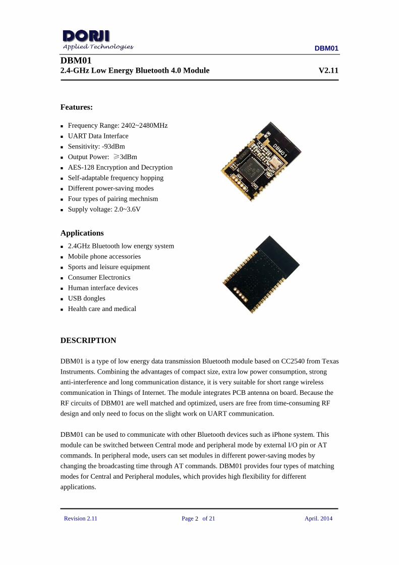
Features:
Frequency Range: 2402~2480MHz
UART Data Interface
Sensitivity: -93dBm
Output Power: ≥3dBm
AES-128 Encryption and Decryption
Self-adaptable frequency hopping
Different power-saving modes
Four types of pairing mechnism
Supply voltage: 2.0~3.6V
Applications
2.4GHz Bluetooth low energy system
Mobile phone accessories
Sports and leisure equipment
Consumer Electronics
Human interface devices
USB dongles
Health care and medical
DESCRIPTION DBM01 is a type of low energy data transmission Bluetooth module based on CC2540 from Texas
Instruments. Combining the advantages of compact size, extra low power consumption, strong
anti-interference and long communication distance, it is very suitable for short range wireless
communication in Things of Internet. The module integrates PCB antenna on board. Because the
RF circuits of DBM01 are well matched and optimized, users are free from time-consuming RF
design and only need to focus on the slight work on UART communication.
DBM01 can be used to communicate with other Bluetooth devices such as iPhone system. This
module can be switched between Central mode and peripheral mode by external I/O pin or AT
commands. In peripheral mode, users can set modules in different power-saving modes by
changing the broadcasting time through AT commands. DBM01 provides four types of matching
modes for Central and Peripheral modules, which provides high flexibility for different
applications.

DBM01
Revision 2.11 Page of 21 April. 2014
3
PIN FUNCTIONS
ANT
GND
3.3V
P2.2
P2.1
P2.0
P1.7/RX
P1.6/TX
DP
DM
P1.5
P1.4
P1.3/SLEEP
GND
RST
P0.0/ROLE
P0.1/PAIRK
P0.2
P0.3
P0.4
P0.5
P0.6/CTRL
P0.7/FACT
P1.0
P1.1
P1.2/CIND
GND3.3VP2.2 P2.1 RST
DBM01
Figure 1: DBM01 Pin Layout
PIN Name Function Description
1 ANT ANT port Optional; DBM01 has antenna on board so it should be floated
2 GND Ground Ground (0V)
3 VCC Power +2.0~3.6V
4~6 P2.2~P2.0 Digital I/O Digital Input/Output pin
7 RX/P1.7 UART port UART interface; RX pin
8 TX/P1.6 UART port UART interface; TX pin
9 DP USB port USB positive +, no function
10 DM USB port USB positive -, no function
11~12 P1.5~P1.4 Digital I/O Digital Input/Output pin
13 SLEEP/P1.3 Digital I Low- effective, the module will be forced to enter into sleep
mode even there is data flow at UART interface. The module
will quit sleep mode when there is a low-to-high pulse on it
14 CIND/P1.2 Digital O Connection indication, Low- unconnected, High-connected
15~16 P1.1~P1.0 Digital I/O Digital Input/Output pin
17 FACT/P0.7 Digital I Low-effective at start-up, default UART data format will be
loaded but flash is not overlapped.
18 CTRL/P0.6 Digital I This pin is used to configure the UART interface to command
mode or transparent data mode. Low- command mode,
High- transparent data mode. When the level of this pin is
changed, users need to wait for 200ms at least before using
DBM01
Revision 2.11 Page of 21 April. 2014
4
UART interface
19~22 P0.5~P0.2 Digital I/O Digital Input/Output pin
23 PAIRK/P0.1 Digital I Matching key port. Low- effective only when PAIRM is 1 and
FORCEK is 0.
24 ROLE/P0.0 Digital I Central/peripheral mode selection, only effective at start-up.
Low Central module, High-Peripheral module
25 RST Input Reset pin; Low effective
26 GND Ground Ground (0V)
Table 1: DBM01 Pin Functions
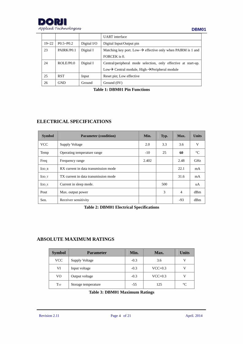
ELECTRICAL SPECIFICATIONS
Symbol Parameter (condition) Min. Typ. Max. Units
VCC Supply Voltage 2.0 3.3 3.6 V
Temp Operating temperature range -10 25 60 °C
Freq Frequency range 2.402 2.48 GHz
IDD_R RX current in data transmission mode 22.1 mA
IDD_T TX current in data transmission mode 31.6 mA
IDD_S Current in sleep mode. 500 uA
Pout Max. output power 3 4 dBm
Sen. Receiver sensitivity -93 dBm
Table 2: DBM01 Electrical Specifications
ABSOLUTE MAXIMUM RATINGS
Symbol Parameter Min. Max. Units
VCC Supply Voltage -0.3 3.6 V
VI Input voltage -0.3 VCC+0.3 V
VO Output voltage -0.3 VCC+0.3 V
TST Storage temperature -55 125 °C
Table 3: DBM01 Maximum Ratings
DBM01
Revision 2.11 Page of 21 April. 2014
5
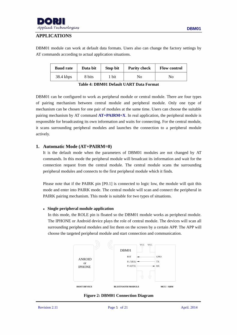
APPLICATIONS DBM01 module can work at default data formats. Users also can change the factory settings by
AT commands according to actual application situations.
Baud rate Data bit Stop bit Parity check Flow control
38.4 kbps 8 bits 1 bit No No
Table 4: DBM01 Default UART Data Format
DBM01 can be configured to work as peripheral module or central module. There are four types
of pairing mechanism between central module and peripheral module. Only one type of
mechanism can be chosen for one pair of modules at the same time. Users can choose the suitable
pairing mechanism by AT command AT+PAIRM=X. In real application, the peripheral module is
responsible for broadcasting its own information and waits for connecting. For the central module,
it scans surrounding peripheral modules and launches the connection to a peripheral module
actively.
1. Automatic Mode (AT+PAIRM=0)
It is the default mode when the parameters of DBM01 modules are not changed by AT
commands. In this mode the peripheral module will broadcast its information and wait for the
connection request from the central module. The central module scans the surrounding
peripheral modules and connects to the first peripheral module which it finds.
Please note that if the PAIRK pin [P0.1] is connected to logic low, the module will quit this
mode and enter into PAIRK mode. The central module will scan and connect the peripheral in
PAIRK pairing mechanism. This mode is suitable for two types of situations.
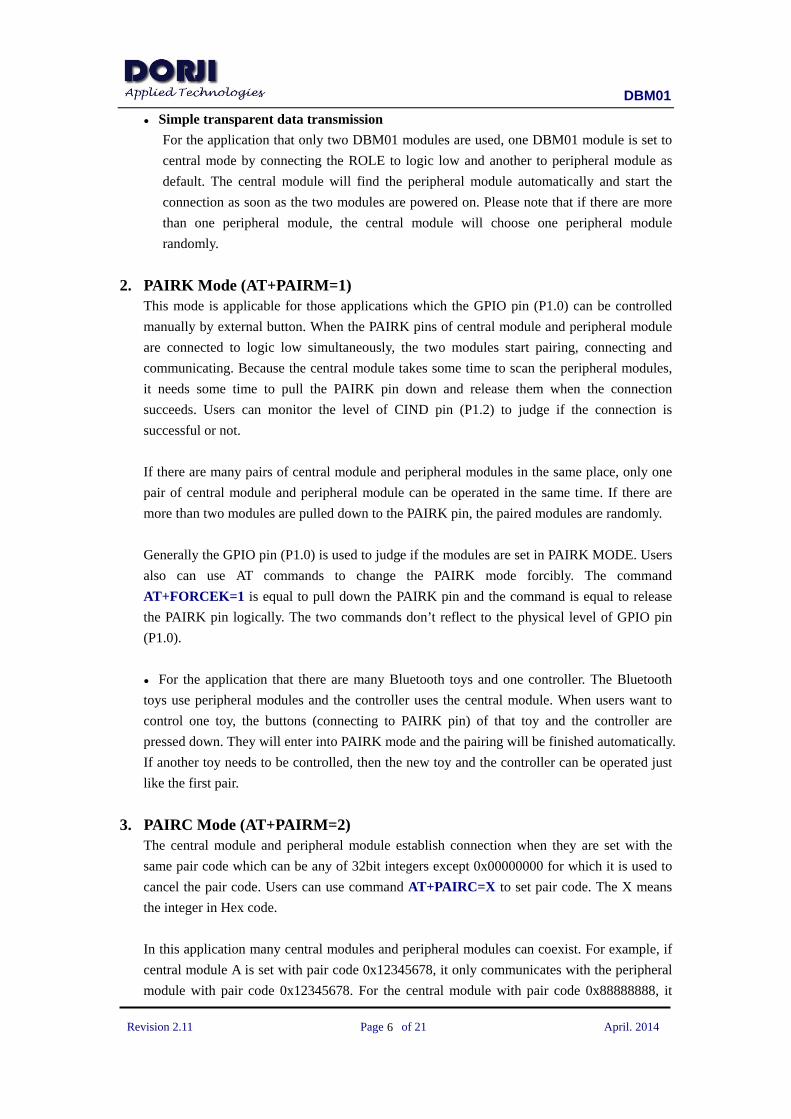
● Single peripheral module application
In this mode, the ROLE pin is floated so the DBM01 module works as peripheral module.
The IPHONE or Android device plays the role of central module. The devices will scan all
surrounding peripheral modules and list them on the screen by a certain APP. The APP will
choose the targeted peripheral module and start connection and communication.
VCCVCC
HOST DEVICE
ANROID orIPHONE
DBM01
BLUETOOTH MODULE MCU / ARM
P1.7(RX)
P1.6(TX)
TX
RX
GPIORST
Figure 2: DBM01 Connection Diagram
DBM01
Revision 2.11 Page of 21 April. 2014
6
● Simple transparent data transmission
For the application that only two DBM01 modules are used, one DBM01 module is set to
central mode by connecting the ROLE to logic low and another to peripheral module as
default. The central module will find the peripheral module automatically and start the
connection as soon as the two modules are powered on. Please note that if there are more
than one peripheral module, the central module will choose one peripheral module
randomly.
2. PAIRK Mode (AT+PAIRM=1) This mode is applicable for those applications which the GPIO pin (P1.0) can be controlled
manually by external button. When the PAIRK pins of central module and peripheral module
are connected to logic low simultaneously, the two modules start pairing, connecting and
communicating. Because the central module takes some time to scan the peripheral modules,
it needs some time to pull the PAIRK pin down and release them when the connection
succeeds. Users can monitor the level of CIND pin (P1.2) to judge if the connection is
successful or not.
If there are many pairs of central module and peripheral modules in the same place, only one
pair of central module and peripheral module can be operated in the same time. If there are
more than two modules are pulled down to the PAIRK pin, the paired modules are randomly.
Generally the GPIO pin (P1.0) is used to judge if the modules are set in PAIRK MODE. Users
also can use AT commands to change the PAIRK mode forcibly. The command
AT+FORCEK=1 is equal to pull down the PAIRK pin and the command is equal to release
the PAIRK pin logically. The two commands don’t reflect to the physical level of GPIO pin
(P1.0).
● For the application that there are many Bluetooth toys and one controller. The Bluetooth
toys use peripheral modules and the controller uses the central module. When users want to
control one toy, the buttons (connecting to PAIRK pin) of that toy and the controller are
pressed down. They will enter into PAIRK mode and the pairing will be finished automatically.
If another toy needs to be controlled, then the new toy and the controller can be operated just
like the first pair.
3. PAIRC Mode (AT+PAIRM=2) The central module and peripheral module establish connection when they are set with the
same pair code which can be any of 32bit integers except 0x00000000 for which it is used to
cancel the pair code. Users can use command AT+PAIRC=X to set pair code. The X means
the integer in Hex code.
In this application many central modules and peripheral modules can coexist. For example, if
central module A is set with pair code 0x12345678, it only communicates with the peripheral
module with pair code 0x12345678. For the central module with pair code 0x88888888, it

DBM01
Revision 2.11 Page of 21 April. 2014
7
only connects to the peripheral module with pair code 0x88888888. If there are more than two
modules set with the same pair code, the central module pairs with one peripheral module
randomly so users should avoid such configuration in the application.
● In wireless LED control based on DBM01 modules, one controller and one LED lamp are
set with the same pair code. Other controllers will not connect the targeted LED lamp and
avoid mal-operation.
● In the production room there are many worktables. Each worktable is equipped with a
peripheral module with an unique pair code which can be labeled on the worktable. The
scanner is equipped with a central module. When the scanner needs to read the data from one
worktable, it can change the pair code of central module to the same as the code on the
worktable and establish communication between the targeted worktable and it.
4. PAIRA Mode (AT+PAIRM=3) This mode refers to the address matching between two Bluetooth modules. Because each
module has an unique address, it can avoid random pairing. Users can use AT command
AT+ADDR to get the Bluetooth module’s address of its own. For example, users can use
AT+ADDR command to get the address of central module X and peripheral module Y. Users
then set the PAIRA of central module to Y by command AT+ADDR=Y and the PAIRA of
peripheral module to X by command AT+ADDR=X. Then users save the change by command
AT+SAVE and reset the module by command AT+RESET to activate PAIRA mode. In this
mode, the two modules only can establish connection when they store the PAIRA of each
other. If IPHONE or other mobile systems scan the peripheral module in this mode, the
system can’t connect the peripheral module.
● This mode is suitable for the applications which the PAIRA of targeted modules are not
needed to change frequently. In parking system, the scanning device in the entrance can be
equipped with one DBM01 module and the Bluetooth module will send the plate number of
cars to the central console equipped with another module. Because the two modules work in
PAIRA mode, they will deny the connection requests from other irrelated Bluetooth devices
automatically.
AT COMMAND SET DBM01 module provides rich AT commands for users to manipulate the modules. Some
commands of DBM01 module come into effect after executing AT+SAVE command but for other
commands they need to execute another command AT+RESET after using command AT+SAVE
in order to reset the module and let it work in new parameters.

DBM01
Revision 2.11 Page of 21 April. 2014
8
COMMAND SET DESCRIPTION
AT+E 、 AT+FORCEK 、 AT+FORCEC 、 AT+AUTOSCAN 、
AT+NOTIFY、AT+TXPOWER、AT+ADVERT、AT+BTPARAM、
AT+BTPARAM2、AT+SLEEP
Users need to execute command
AT+SAVE after using these
commands in the left
AT+NAME 、 AT+UART 、 AT+FLOW 、 AT+ROLE 、
AT+PAIRM、AT+PAIRC、AT+PAIRA
Users need to execute command
AT+SAVE and AT+RESET after
using these commands in the left
Table 5: DBM01 Command Sets
When users send commands to DBM01 for the first time after powering on the module, the CTRL
pin (P0.6) of module should be connect to logic low so the module can enter into command mode
and start to receive AT commands. Please note if the module is in sleep mode, it might not respond
to the AT commands. Please check the SLEEP MODE section for how to quit sleep mode.
1. Testing command
Command Type Response Description
AT OK Testing command
2. Inquiry command
AT+HELP Commands:
E
HELP
SEND
CFG
SAVE
LOAD
LOADDEFT
NAME
UART
FLOW
ROLE
PAIRM
PAIRC
PAIRA
FORCEK
FORCEC
CONN
DISC
SCAN
DEVLIST
This command is used to list all the
supported commands by DBM01
module
DBM01
Revision 2.11 Page of 21 April. 2014
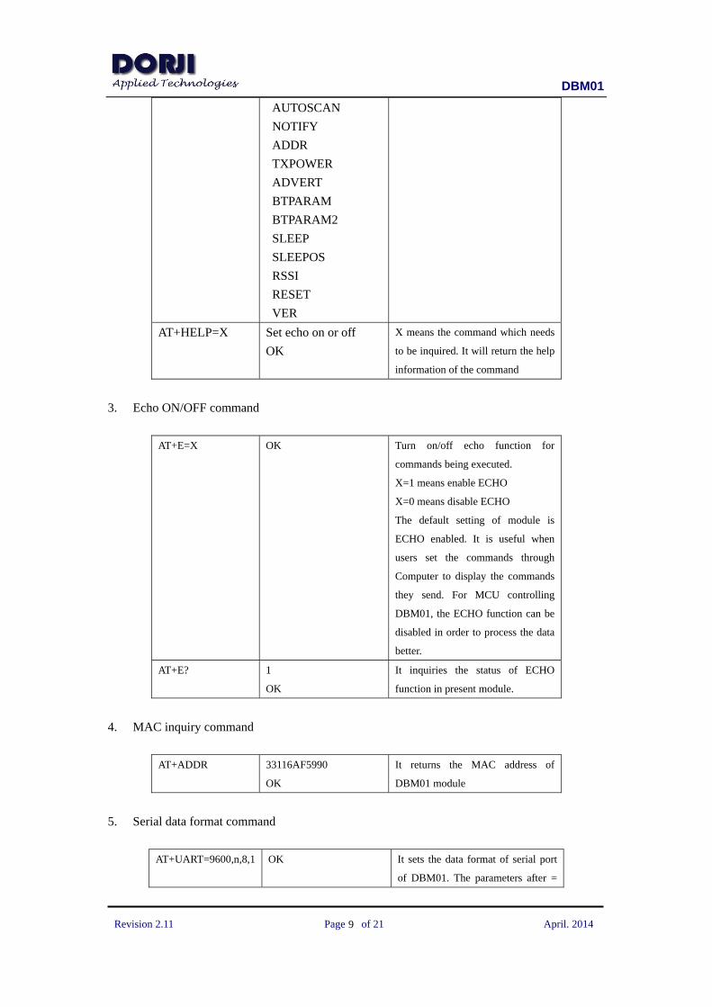
9
AUTOSCAN
NOTIFY
ADDR
TXPOWER
ADVERT
BTPARAM
BTPARAM2
SLEEP
SLEEPOS
RSSI
RESET
VER
AT+HELP=X Set echo on or off
OK
X means the command which needs
to be inquired. It will return the help
information of the command
3. Echo ON/OFF command
AT+E=X OK Turn on/off echo function for
commands being executed.
X=1 means enable ECHO
X=0 means disable ECHO
The default setting of module is
ECHO enabled. It is useful when
users set the commands through
Computer to display the commands
they send. For MCU controlling
DBM01, the ECHO function can be
disabled in order to process the data
better.
AT+E? 1
OK
It inquiries the status of ECHO
function in present module.
4. MAC inquiry command
AT+ADDR 33116AF5990
OK
It returns the MAC address of
DBM01 module
5. Serial data format command
AT+UART=9600,n,8,1 OK It sets the data format of serial port
of DBM01. The parameters after =
DBM01
Revision 2.11 Page of 21 April. 2014
10
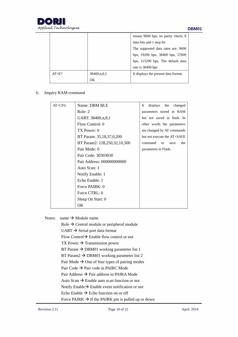
means 9600 bps, no parity check, 8
data bits and 1 stop bit
The supported data rates are: 9600
bps, 19200 bps, 38400 bps, 57600
bps, 115200 bps. The default data
rate is 38400 bps
AT+E? 38400,n,8,1
OK
It displays the present data format
6. Inquiry RAM command
AT+CFG Name: DBM BLE
Role: 2
UART: 38400,n,8,1
Flow Control: 0
TX Power: 0
BT Param: 35,18,37,0,200
BT Param2: 128,250,32,10,500
Pair Mode: 0
Pair Code: 30303030
Pair Address: 000000000000
Auto Scan: 1
Notify Enable: 1
Echo Enable: 1
Force PAIRK: 0
Force CTRL: 0
Sleep On Start: 0
OK
It displays the changed
parameters stored in RAM
but not saved in flash. In
other words the parameters
are changed by AT commands
but not execute the AT+SAVE
command to save the
parameters in Flash.
Notes: name Module name
Role Central module or peripheral module
UART Serial port data format
Flow Control Enable flow control or not
TX Power Transmission power
BT Param DBM01 working parameter list 1
BT Param2 DBM01 working parameter list 2
Pair Mode One of four types of pairing modes
Pair Code Pair code in PAIRC Mode
Pair Address Pair address in PAIRA Mode
Auto Scan Enable auto scan function or not
Notify Enable Enable event notification or not
Echo Enable Echo function on or off
Force PAIRK If the PAIRK pin is pulled up or down
DBM01
Revision 2.11 Page of 21 April. 2014
11
Force CTRL If the CTRL pin is pulled up or down
Sleep On Start If the module enters into sleep mode when start-up.
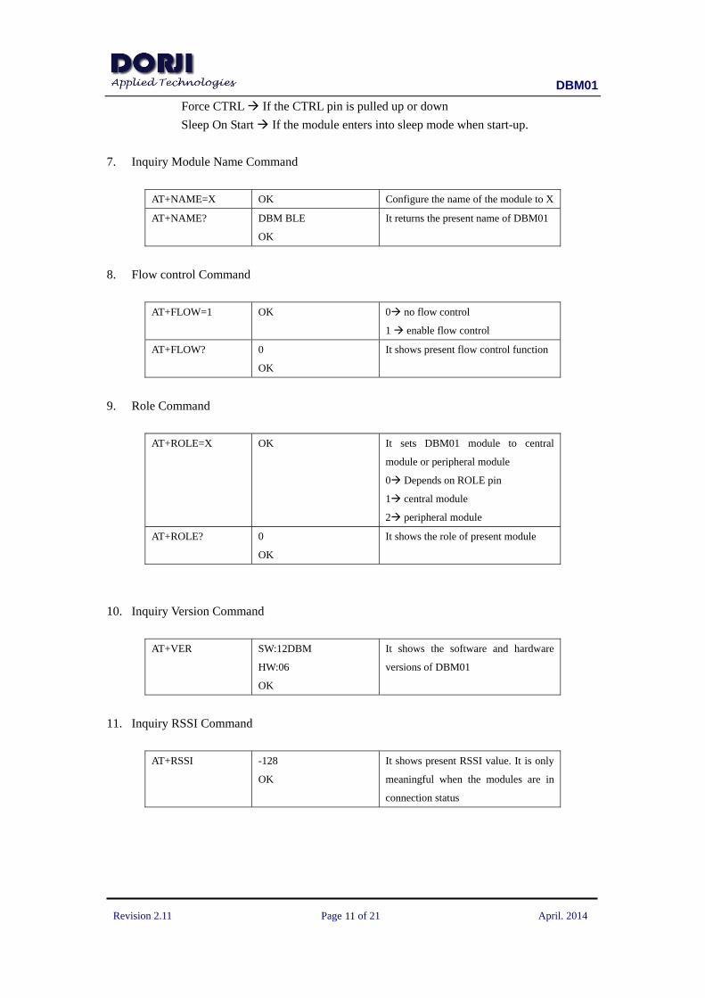
7. Inquiry Module Name Command
AT+NAME=X OK Configure the name of the module to X
AT+NAME? DBM BLE
OK
It returns the present name of DBM01
8. Flow control Command
AT+FLOW=1 OK 0 no flow control
1 enable flow control
AT+FLOW? 0
OK
It shows present flow control function
9. Role Command
AT+ROLE=X OK It sets DBM01 module to central
module or peripheral module
0 Depends on ROLE pin
1 central module
2 peripheral module
AT+ROLE? 0
OK
It shows the role of present module
10. Inquiry Version Command
AT+VER SW:12DBM
HW:06
OK
It shows the software and hardware
versions of DBM01
11. Inquiry RSSI Command
AT+RSSI -128
OK
It shows present RSSI value. It is only
meaningful when the modules are in
connection status
DBM01
Revision 2.11 Page of 21 April. 2014
12
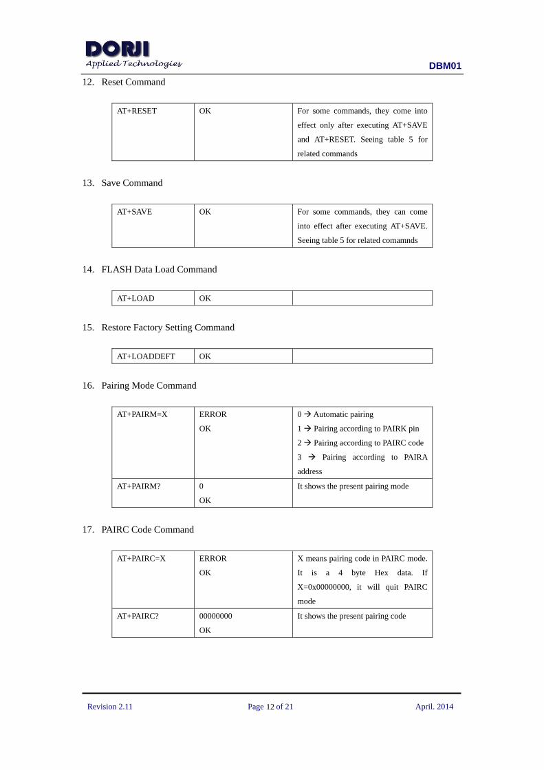
12. Reset Command
AT+RESET OK For some commands, they come into
effect only after executing AT+SAVE
and AT+RESET. Seeing table 5 for
related commands
13. Save Command
AT+SAVE OK For some commands, they can come
into effect after executing AT+SAVE.
Seeing table 5 for related comamnds
14. FLASH Data Load Command
AT+LOAD OK
15. Restore Factory Setting Command
AT+LOADDEFT OK
16. Pairing Mode Command
AT+PAIRM=X ERROR
OK
0 Automatic pairing
1 Pairing according to PAIRK pin
2 Pairing according to PAIRC code
3 Pairing according to PAIRA
address
AT+PAIRM? 0
OK
It shows the present pairing mode
17. PAIRC Code Command
AT+PAIRC=X ERROR
OK
X means pairing code in PAIRC mode.
It is a 4 byte Hex data. If
X=0x00000000, it will quit PAIRC
mode
AT+PAIRC? 00000000
OK
It shows the present pairing code

DBM01
Revision 2.11 Page of 21 April. 2014
13
18. PAIRA Address Command
AT+PAIRA=X OK X means the address of the paired
DBM01 module
AT+PAIRA? 9059AF1624AB
OK
It shows the present pairing code
19. PAIRK Pin Control Command
AT+FORCEK=X OK 0 No process
1 Virtually pull down the PAIRK
AT+ FORCEK? 0
OK
20. CTRL Pin Control Command
AT+FORCEC=X OK 0 No process
1 Virtually pull down the CTRL
AT+ FORCEC? 0
OK
21. Connecting Targeted Peripheral Device Command
AT+CONN=X OK This command is only available for
central module. X means the sequence
number of the peripheral devices
scanned by central module. X=0 means
the first peripheral device being found.
This command is to let the central
module connect the X peripheral
module.
22. Disconnect Command
AT+DISC OK Disconnect the present link
23. Send Data Command
AT+SEND=X N bytes sent
OK
X refers to the data needing to be sent.
The data is in HEX coding and the
length of data package should not
exceed 20 bytes. N means the number

DBM01
Revision 2.11 Page of 21 April. 2014
14
of bytes rendered to buffer area and not
indicate the data is sent out
successfully by wireless
24. Scan Command (central module only)
AT+SCAN OK
+DEVS: 0 found
+DEVE
It triggers the central module to scan
surrounding peripheral modules. The
result will be transferred to the host at
the form of events such as +DEVS.
25. Automatic Scan Command (central module only)
AT+AUTOSCAN=X 1
OK
0 Disable autoscan
1 Enable autoscan
When this function is enabled, DBM01 will
start scanning automatically in the situations
of module start-up, scanning failure,
disconnecting, etc.
AT+ AUTOSCAN? 1
OK
26. Broadcast Command (peripheral module only)
AT+ADVERT=X OK 0 Stop broadcasting
1 Start broadcasting
AT+ ADVERT? 1
OK
27. List Peripheral Module Command (central module only)
AT+DEVLIST +DEVS: 1 found
+DEV:
0, 0x9059AF1624AB, 0,
00000000
+DEVE
OK
This command will list the information
of all the peripheral modules being
scanned. +DEVS: shows the number of
peripheral devices.
Among the parameters following
+DEV, 0 refers to the index of the
peripheral module, 0x9059AF1624AB
means the address of DBM01 module,
the second 0 refers to the pairing mode
and the last digits refers to the PAIRC
code.
DBM01
Revision 2.11 Page of 21 April. 2014
15
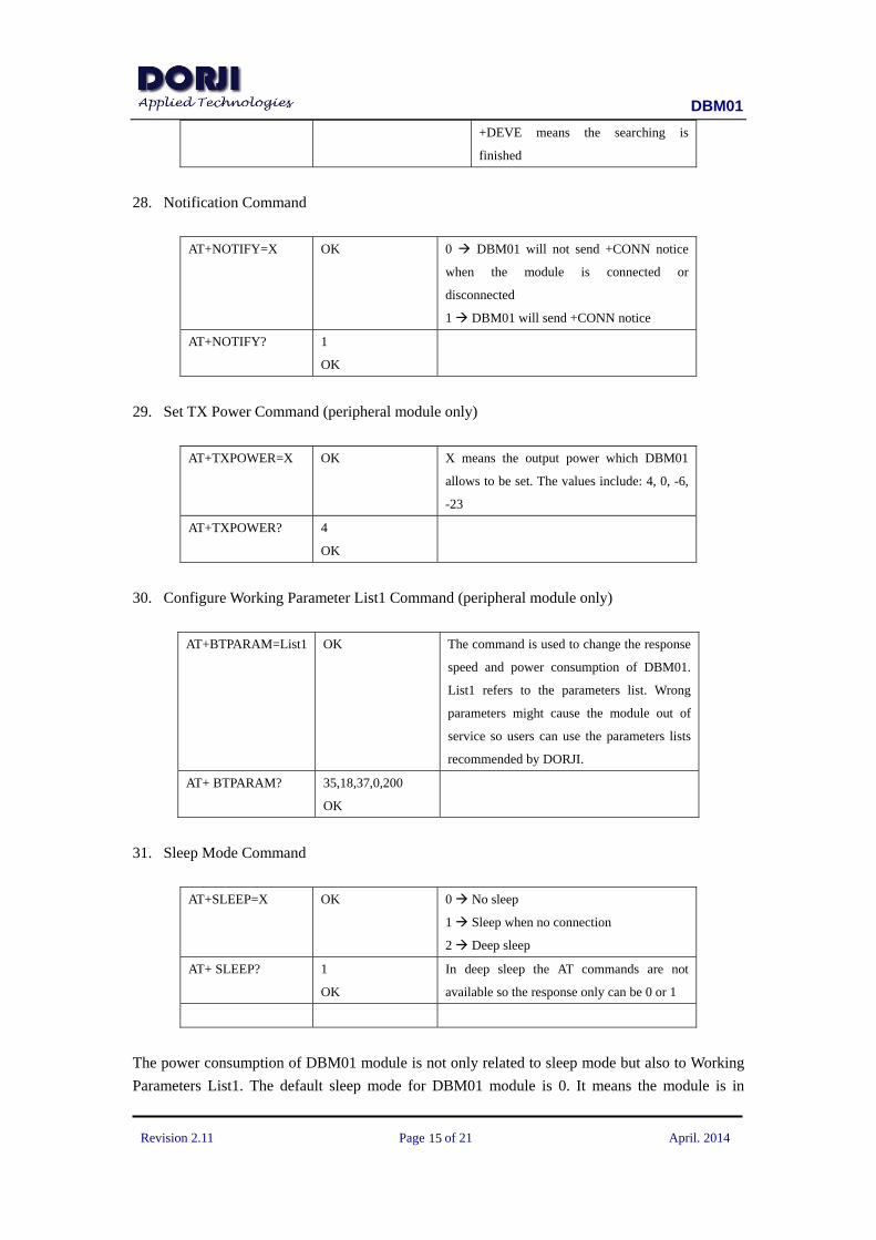
+DEVE means the searching is
finished
28. Notification Command
AT+NOTIFY=X OK 0 DBM01 will not send +CONN notice
when the module is connected or
disconnected
1 DBM01 will send +CONN notice
AT+NOTIFY? 1
OK
29. Set TX Power Command (peripheral module only)
AT+TXPOWER=X OK X means the output power which DBM01
allows to be set. The values include: 4, 0, -6,
-23
AT+TXPOWER? 4
OK
30. Configure Working Parameter List1 Command (peripheral module only)
AT+BTPARAM=List1 OK The command is used to change the response
speed and power consumption of DBM01.
List1 refers to the parameters list. Wrong
parameters might cause the module out of
service so users can use the parameters lists
recommended by DORJI.
AT+ BTPARAM? 35,18,37,0,200
OK
31. Sleep Mode Command
AT+SLEEP=X OK 0 No sleep
1 Sleep when no connection
2 Deep sleep
AT+ SLEEP? 1
OK
In deep sleep the AT commands are not
available so the response only can be 0 or 1
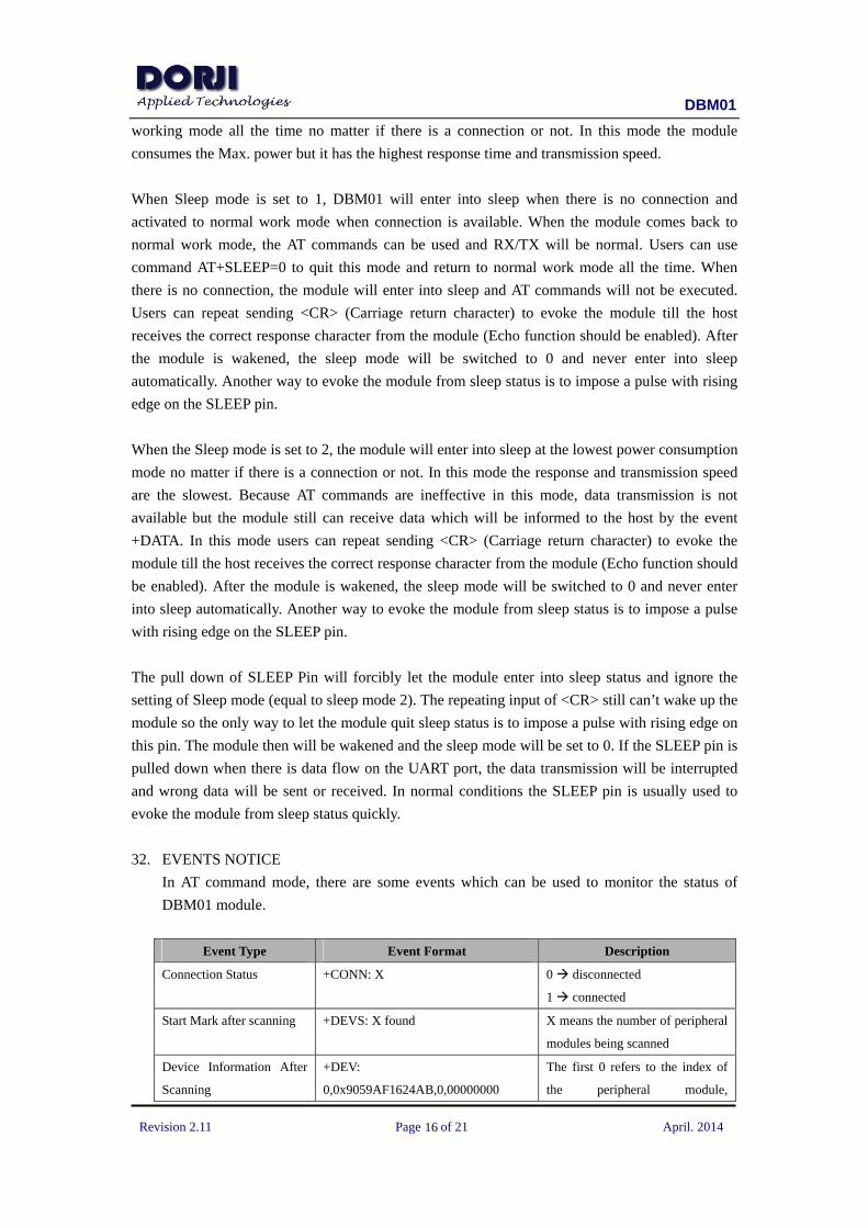
The power consumption of DBM01 module is not only related to sleep mode but also to Working
Parameters List1. The default sleep mode for DBM01 module is 0. It means the module is in
DBM01
Revision 2.11 Page of 21 April. 2014
16
working mode all the time no matter if there is a connection or not. In this mode the module
consumes the Max. power but it has the highest response time and transmission speed.
When Sleep mode is set to 1, DBM01 will enter into sleep when there is no connection and
activated to normal work mode when connection is available. When the module comes back to
normal work mode, the AT commands can be used and RX/TX will be normal. Users can use
command AT+SLEEP=0 to quit this mode and return to normal work mode all the time. When
there is no connection, the module will enter into sleep and AT commands will not be executed.
Users can repeat sending <CR> (Carriage return character) to evoke the module till the host
receives the correct response character from the module (Echo function should be enabled). After
the module is wakened, the sleep mode will be switched to 0 and never enter into sleep
automatically. Another way to evoke the module from sleep status is to impose a pulse with rising
edge on the SLEEP pin.
When the Sleep mode is set to 2, the module will enter into sleep at the lowest power consumption
mode no matter if there is a connection or not. In this mode the response and transmission speed
are the slowest. Because AT commands are ineffective in this mode, data transmission is not
available but the module still can receive data which will be informed to the host by the event
+DATA. In this mode users can repeat sending <CR> (Carriage return character) to evoke the
module till the host receives the correct response character from the module (Echo function should
be enabled). After the module is wakened, the sleep mode will be switched to 0 and never enter
into sleep automatically. Another way to evoke the module from sleep status is to impose a pulse
with rising edge on the SLEEP pin.
The pull down of SLEEP Pin will forcibly let the module enter into sleep status and ignore the
setting of Sleep mode (equal to sleep mode 2). The repeating input of <CR> still can’t wake up the
module so the only way to let the module quit sleep status is to impose a pulse with rising edge on
this pin. The module then will be wakened and the sleep mode will be set to 0. If the SLEEP pin is
pulled down when there is data flow on the UART port, the data transmission will be interrupted
and wrong data will be sent or received. In normal conditions the SLEEP pin is usually used to
evoke the module from sleep status quickly.
32. EVENTS NOTICE
In AT command mode, there are some events which can be used to monitor the status of
DBM01 module.
Event Type Event Format Description
Connection Status +CONN: X 0 disconnected
1 connected
Start Mark after scanning +DEVS: X found X means the number of peripheral
modules being scanned
Device Information After
Scanning
+DEV:
0,0x9059AF1624AB,0,00000000
The first 0 refers to the index of
the peripheral module,

DBM01
Revision 2.11 Page of 21 April. 2014
17
0x9059AF1624AB means the
address of DBM01 module, the
second 0 refers to the pairing
mode and the last digits refers to
the PAIRC code.
End Mark After Scanning +DEVE
Data Received notice +DATA: x X refers to the received data in
Hex format. When the data
package is too large, the package
will be split and produce multiple
+DATA notices
POWER CONSUMPTION
The actual power consumption of DBM01 is not only determined by the sleep modes but also
depends on the broadcasting frequency, scanning frequency, TX power, response speed and the
connection status of GPIO pins. In order to let the modules work with the best performance, users
need to choose the right working parameters list1 according to the applications. The default
factory parameters for DBM01 module is speed priority so the power consumption is the
maximum.
All of the GPIO pins are internally pull-up. When they are connected with GND, there will be leak
current so it will be better to keep the unused GPIO pins floated in order to reduce power
consumption. What’s more the function of some GPIO pins can be realized by AT commands. For
example, the command AT+ROLE=1 is equal to the pull-down of ROLE and AT+FORCEC=1 is
equal to the pull-down of PAIRK.
When peripheral module is not connected, it will broadcast frequently. It will reduce the power
consumption by lowering down the broadcasting frequency. The broadcasting function of
peripheral module can be cancelled by AT command AT+ADVERT=0 but it will not be scanned
by the central module. AT command AT+BTPARAM=List1 can be used to adjust the broadcasting
frequency of peripheral module.
If the central module doesn’t connect with a peripheral module, it will scan the surrounding
devices frequently, which makes great contribution to the power consumption Users also can use
AT command AT+AUTOSCAN=0 to turn off the auto-scan function. It will lower down the power
consumption of central module in unconnected status.
When the peripheral module is connected with a central, the working parameters list is determined
by the peripheral module so the power consumption of central module will be decided by the
connected peripheral module.
DBM01
Revision 2.11 Page of 21 April. 2014
18
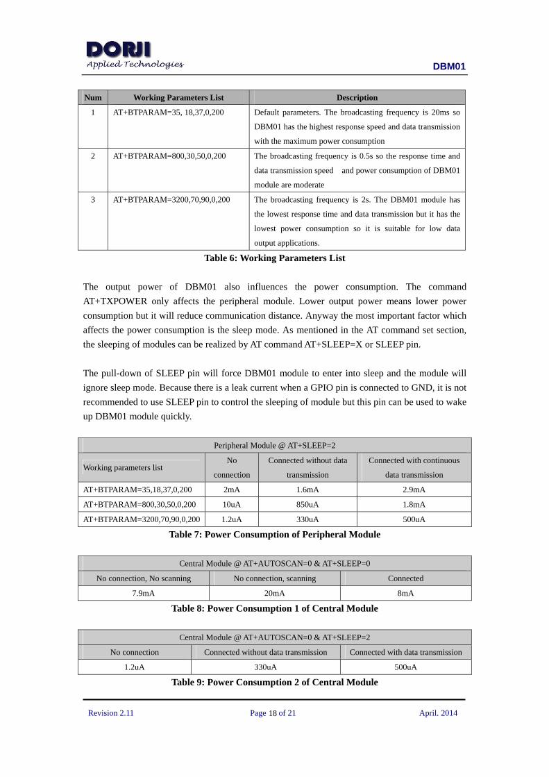
Num Working Parameters List Description
1 AT+BTPARAM=35, 18,37,0,200 Default parameters. The broadcasting frequency is 20ms so
DBM01 has the highest response speed and data transmission
with the maximum power consumption
2 AT+BTPARAM=800,30,50,0,200 The broadcasting frequency is 0.5s so the response time and
data transmission speed and power consumption of DBM01
module are moderate
3 AT+BTPARAM=3200,70,90,0,200 The broadcasting frequency is 2s. The DBM01 module has
the lowest response time and data transmission but it has the
lowest power consumption so it is suitable for low data
output applications.
Table 6: Working Parameters List
The output power of DBM01 also influences the power consumption. The command
AT+TXPOWER only affects the peripheral module. Lower output power means lower power
consumption but it will reduce communication distance. Anyway the most important factor which
affects the power consumption is the sleep mode. As mentioned in the AT command set section,
the sleeping of modules can be realized by AT command AT+SLEEP=X or SLEEP pin.
The pull-down of SLEEP pin will force DBM01 module to enter into sleep and the module will
ignore sleep mode. Because there is a leak current when a GPIO pin is connected to GND, it is not
recommended to use SLEEP pin to control the sleeping of module but this pin can be used to wake
up DBM01 module quickly.
Peripheral Module @ AT+SLEEP=2
Working parameters list No
connection
Connected without data
transmission
Connected with continuous
data transmission
AT+BTPARAM=35,18,37,0,200 2mA 1.6mA 2.9mA
AT+BTPARAM=800,30,50,0,200 10uA 850uA 1.8mA
AT+BTPARAM=3200,70,90,0,200 1.2uA 330uA 500uA
Table 7: Power Consumption of Peripheral Module
Central Module @ AT+AUTOSCAN=0 & AT+SLEEP=0
No connection, No scanning No connection, scanning Connected
7.9mA 20mA 8mA
Table 8: Power Consumption 1 of Central Module
Central Module @ AT+AUTOSCAN=0 & AT+SLEEP=2
No connection Connected without data transmission Connected with data transmission
1.2uA 330uA 500uA
Table 9: Power Consumption 2 of Central Module
DBM01
Revision 2.11 Page of 21 April. 2014
19
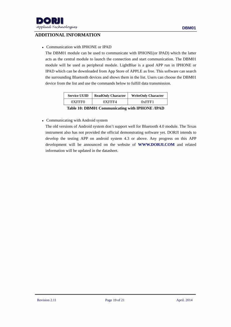
ADDITIONAL INFORMATION
● Communication with IPHONE or IPAD
The DBM01 module can be used to communicate with IPHONE(or IPAD) which the latter
acts as the central module to launch the connection and start communication. The DBM01
module will be used as peripheral module. LightBlue is a good APP run in IPHONE or
IPAD which can be downloaded from App Store of APPLE as free. This software can search
the surrounding Bluetooth devices and shows them in the list. Users can choose the DBM01
device from the list and use the commands below to fulfill data transmission.
Service UUID ReadOnly Character WriteOnly Character
0XFFF0 0XFFF4 0xFFF1
Table 10: DBM01 Communicating with IPHONE /IPAD
● Communicating with Android system
The old versions of Android system don’t support well for Bluetooth 4.0 module. The Texas
instrument also has not provided the official demonstrating software yet. DORJI intends to
develop the testing APP on android system 4.3 or above. Any progress on this APP
development will be announced on the website of WWW.DORJI.COM and related
information will be updated in the datasheet.
DBM01
Revision 2.11 Page of 21 April. 2014
20
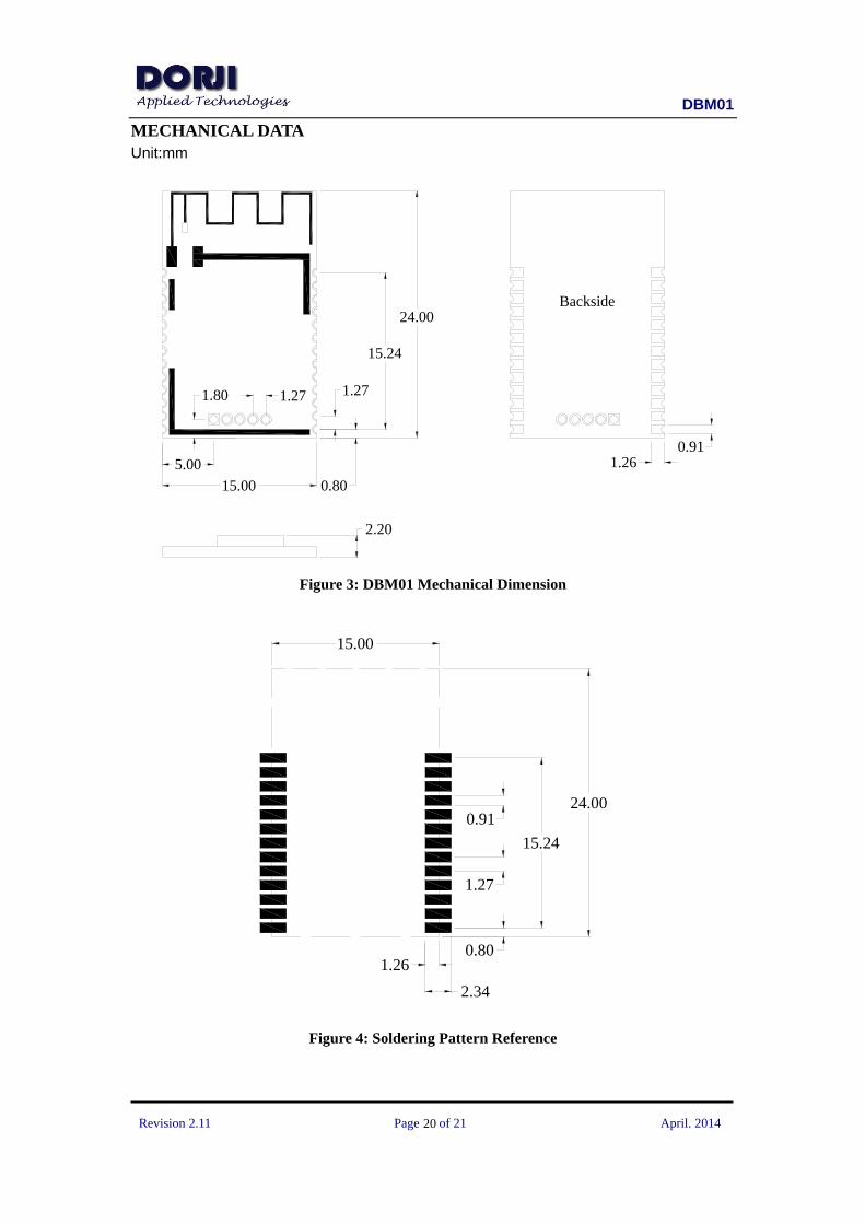
MECHANICAL DATA Unit:mm
15.24
1.27
0.80
24.00
15.00
0.911.26
1.80 1.27
5.00
Backside
2.20
Figure 3: DBM01 Mechanical Dimension
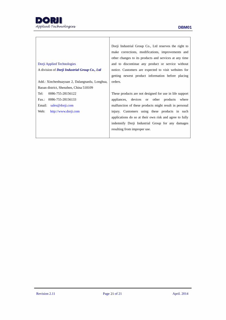
1.26
2.34
0.91
1.27
15.24
0.80
15.00
24.00
Figure 4: Soldering Pattern Reference
DBM01
Revision 2.11 Page of 21 April. 2014
21
Dorji Applied Technologies
A division of Dorji Industrial Group Co., Ltd
Add.: Xinchenhuayuan 2, Dalangnanlu, Longhua,
Baoan district, Shenzhen, China 518109
Tel: 0086-755-28156122
Fax.: 0086-755-28156133
Email: [email protected]
Web: http://www.dorji.com
Dorji Industrial Group Co., Ltd reserves the right to
make corrections, modifications, improvements and
other changes to its products and services at any time
and to discontinue any product or service without
notice. Customers are expected to visit websites for
getting newest product information before placing
orders.
These products are not designed for use in life support
appliances, devices or other products where
malfunction of these products might result in personal
injury. Customers using these products in such
applications do so at their own risk and agree to fully
indemnify Dorji Industrial Group for any damages
resulting from improper use.