Day1 Modelling of Power Electronic Converters for ... · DigSILENT Modelling of Power Electronic...
24
DigSILENT Modelling of Power Electronic Converters for Distributed Generation Networks Roozbeh Kabiri Prof. Grahame Holmes Dr. Brendan McGrath
Transcript of Day1 Modelling of Power Electronic Converters for ... · DigSILENT Modelling of Power Electronic...

DigSILENT Modelling of Power Electronic Converters for Distributed Generation
Networks
Roozbeh Kabiri
Prof. Grahame Holmes
Dr. Brendan McGrath

Outline
– Introduction
– Distributed Generation Unit Modelling
– Implementation in DigSILENT
– Simulation Models and Results– Distributed Generation Unit
– Microgrid
– Recommendations for DigSILENT
RMIT University©2013 School of Electrical and Computer Engineering 2
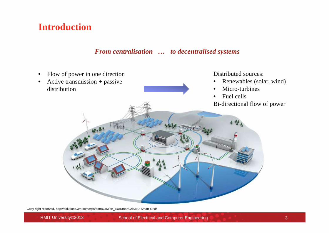
Introduction
From centralisation … to decentralised systems
RMIT University©2013 School of Electrical and Computer Engineering 3
• Flow of power in one direction• Active transmission + passive
distribution
Distributed sources:• Renewables (solar, wind)• Micro-turbines• Fuel cellsBi-directional flow of power
Copy right reserved, http://solutions.3m.com/wps/portal/3M/en_EU/SmartGrid/EU-Smart-Grid/
Introduction
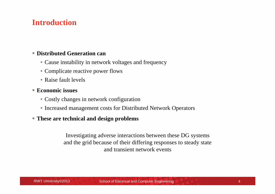
� Distributed Generation can
• Cause instability in network voltages and frequency
• Complicate reactive power flows
• Raise fault levels
� Economic issues
• Costly changes in network configuration
• Increased management costs for Distributed Network Operators
� These are technical and design problems
RMIT University©2013 School of Electrical and Computer Engineering 4
Investigating adverse interactions between these DG systems and the grid because of their differing responses to steady state
and transient network events
Introduction
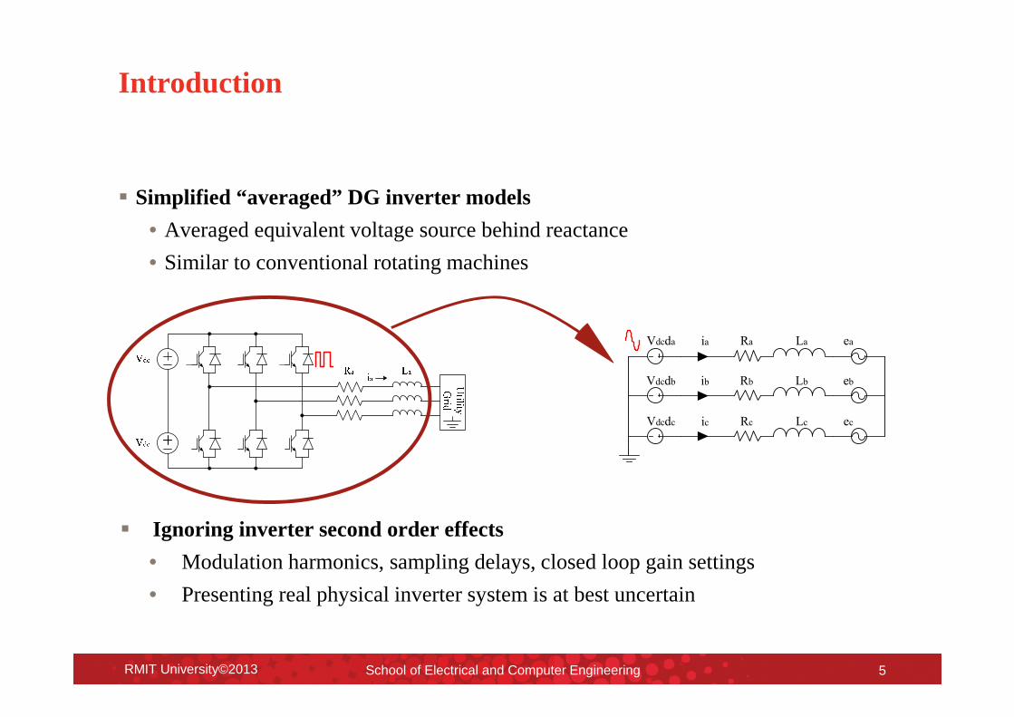
� Simplified “averaged” DG inverter models
• Averaged equivalent voltage source behind reactance
• Similar to conventional rotating machines
� Ignoring inverter second order effects
• Modulation harmonics, sampling delays, closed loop gain settings
• Presenting real physical inverter system is at best uncertain
RMIT University©2013 School of Electrical and Computer Engineering 5
Ra
Rb
Rc
La
Lc
Lb
ea
ec
eb
Vdcda
Vdcdc
Vdcdb
ia
ib
ic

Outline
– Introduction
– Distributed Generation Unit Modelling
– Implementation in DigSILENT
– Simulation Models and Results– Distributed Generation Unit
– Microgrid
– Recommendations for DigSILENT
RMIT University©2013 School of Electrical and Computer Engineering 6

Distributed Generation Unit Modelling
RMIT University©2013 School of Electrical and Computer Engineering 7
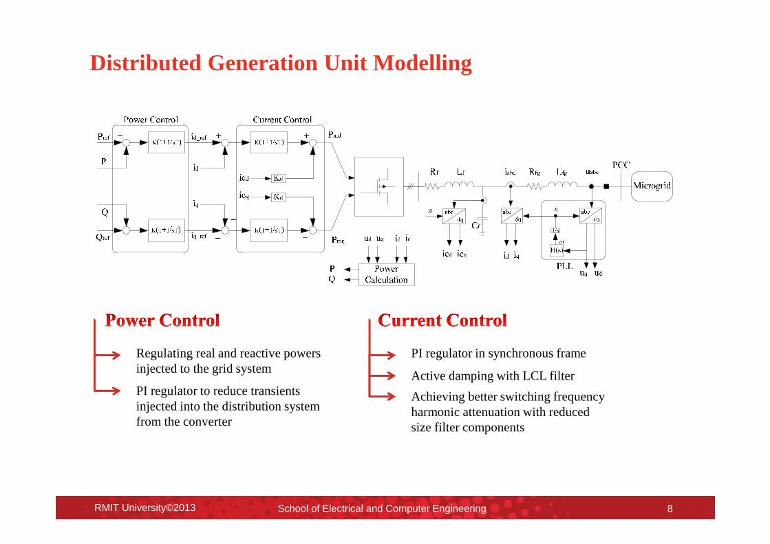
Distributed Generation Unit Modelling
RMIT University©2013 School of Electrical and Computer Engineering 8
Regulating real and reactive powers injected to the grid system
PI regulator to reduce transients injected into the distribution system from the converter
PI regulator in synchronous frame
Active damping with LCL filter
Achieving better switching frequency harmonic attenuation with reduced size filter components
Outline
– Introduction
– Distributed Generation Unit Modelling
– Implementation in DigSILENT
– Simulation Models and Results– Distributed Generation Unit
– Microgrid
– Recommendations for DigSILENT
RMIT University©2013 School of Electrical and Computer Engineering 9

Implementation in DigSILENT
• Inverter modelling based on the “PWM converter” model with two DC connections
• DC source to represent the primary source of power
• Using two “Common Impedances” for inverter-side and grid-side inductors, and a “Shunt/Filter C” located in between these inductances for filter capacitance
RMIT University©2013 School of Electrical and Computer Engineering 10

Implementation in DigSILENT
• Controller Frame
RMIT University©2013 School of Electrical and Computer Engineering 11

Implementation in DigSILENT
• Sampling and Clock Generation
RMIT University©2013 School of Electrical and Computer Engineering 12

Implementation in DigSILENT
RMIT University©2013 School of Electrical and Computer Engineering 13
Calculating the actual real and reactive power for the converter
Higher level of control generates the power setpoints (���� & ����)
Capacitor currents added as additional feedback signals after the PI regulators, with a damping gain of ��
� = ���� + ����� = ���� − ����
Final outputs ��_��� & ��_���Final outputs The commanded dq frame
voltages, required to be produced by the converter power stage
→
→
State of the art closed loop current regulator [1] �� ≈ ��(�� + ���)��� �� = 10 ��⁄
[1] D. G. Holmes, T. A. Lipo, B. P. McGrath, and W. Y. Kong, "Optimized Design of Stationary Frame Three Phase AC Current Regulators," Power Electronics, IEEE Transactions on, vol. 24, pp. 2417-2426, 2009.

Outline
– Introduction
– Distributed Generation Unit Modelling
– Implementation in DigSILENT
– Simulation Models and Results– Distributed Generation Unit
– Microgrid
– Recommendations for DigSILENT
RMIT University©2013 School of Electrical and Computer Engineering 14

Simulation Models and Results
Distributed Generation Unit
RMIT University©2013 School of Electrical and Computer Engineering 15
Parameters Value
Filter (��) 12.7 (mH)
Grid-side Filter (���) 1.27 (mH)
Shunt ( �) 15 (!")
Sampling frequency 10 (kHz)
Switching frequency 5 (kHz)
DC Source 1000 (V)
Grid voltage (RMS) 400 (V)
Grid frequency 50 (Hz)
Power rating 10 (kW)

Simulation Models and Results
Distributed Generation Unit
RMIT University©2013 School of Electrical and Computer Engineering 16
DigSILENT PSIM

Simulation Models and Results
Distributed Generation Unit
RMIT University©2013 School of Electrical and Computer Engineering 17

Simulation Models and Results
Microgrid
RMIT University©2013 School of Electrical and Computer Engineering 18
DG Parameters Value
Number of DG units 20
Switching frequency 5 – 6 kHz
Total installed load 200 kW – 150kVar
DG penetration 40 % (max)
SG Data Value
Rated power 850 kVA
Voltage rating 400/231 V
Rated power factor 0.8

Simulation Models and Results
Microgrid
RMIT University©2013 School of Electrical and Computer Engineering 19

Simulation Models and Results
Microgrid
RMIT University©2013 School of Electrical and Computer Engineering 20
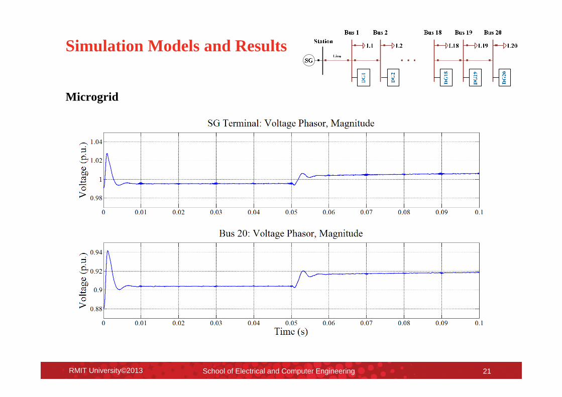
Simulation Models and Results
Microgrid
RMIT University©2013 School of Electrical and Computer Engineering 21

Outline
– Introduction
– Distributed Generation Unit Modelling
– Implementation in DigSILENT
– Simulation Models and Results– Distributed Generation Unit
– Microgrid
– Recommendations for DigSILENT
RMIT University©2013 School of Electrical and Computer Engineering 22

Recommendations for DigSILENT
� New power elements
• Single-phase PWM converter,
• 4-leg PWM converter
� Iteration removal
� Increased numerical stability
RMIT University©2013 School of Electrical and Computer Engineering 23

Thank you