Day 3 course - ITSO
82
Day 3 course Network Planning and Link Budget Analysis 1
Transcript of Day 3 course - ITSO

Day 3 course
Network Planning and Link Budget Analysis
1

1- Satellite Network Topology
Topologies Satellites networks have various topologies. We can enumerate the following :
• Star Networks
• Mesh Networks
• SCPC
• DVB
• Cellular backhaul
2

1- Satellite Network Topology
Star Network This is how a star data, TDM/TDMA VSAT network works using a hub station, usually six metres or more in size and small VSAT antennas (between 75 centimetres and 2.4 metres). All the channels are shared and the remote terminals are online, offering fast response times. Historically, TDM/TDMA systems competed with terrestrial X.25 or frame relay connections, but as VSAT transmit data rates have risen to 2 Mbps or more and receive rates begin approaching 100 Mbps DSL and MPLS services have become the main competitors in most markets.
3

1- Satellite Network Topology
Star Network
4

1- Satellite Network Topology
Mesh Network However, mesh networks which use capacity on a demand assigned multiple access (DAMA) basis take a different approach. The master control station merely acts as a controller and facilitator rather than a hub through which traffic passes as in a star network. However, these connections take a little time to set-up and thus, mesh/DAMA systems are often equated to a terrestrial dial-up connection.
5

1- Satellite Network Topology
Mesh Network
6
1- Satellite Network Topology
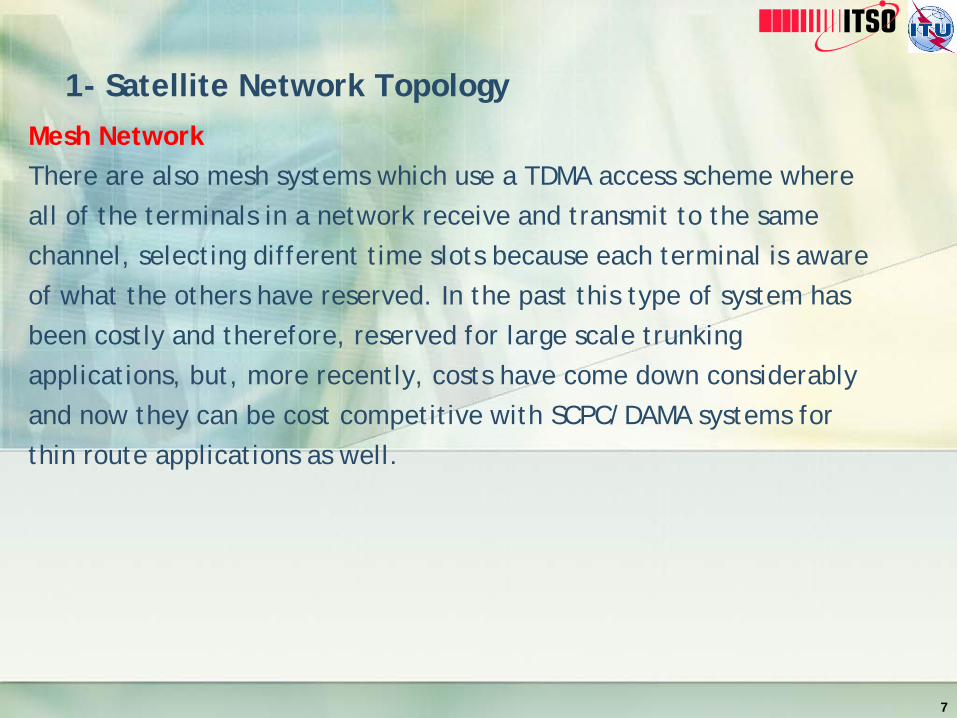
Mesh Network There are also mesh systems which use a TDMA access scheme where all of the terminals in a network receive and transmit to the same channel, selecting different time slots because each terminal is aware of what the others have reserved. In the past this type of system has been costly and therefore, reserved for large scale trunking applications, but, more recently, costs have come down considerably and now they can be cost competitive with SCPC/DAMA systems for thin route applications as well.
7

1- Satellite Network Topology
SCPC Network Point-to-point SCPC (single channel per carrier) links are the satellite equivalent of a terrestrial leased line connection. They are usually set-up on a permanent, 24 hour basis and are thus more costly in satellite capacity and less efficient if not used all the time. However, they do support dedicated high bandwidth links without any sharing or contention. Typically we only classify terminals running rates from 9.6 kbps to 2 Mbps as VSATs (any ) and can easily be used to carry data, voice and even video traffic.
8

1- Satellite Network Topology
SCPCNetwork
9

1- Satellite Network Topology
Other Networks
All other systems are usually a variation on one of the themes described above, either in a star, mesh or hybrid (star and mesh) configuration. Most of the TDM/TDMA manufacturers also offer a mesh product which can be deployed in a hybrid-ised configuration, sharing common components such as antennas and RF units, at a remote site.
10

2- Accessing schemes
The primary objective of the VSAT networks is to maximize the use of common satellite and other resources amongst all VSAT sites.
The methods by which these networks optimize the use of satellite capacity, and spectrum utilization in a flexible and cost-effective manner are referred to as satellite access schemes.
Each of the above topologies is associated with an appropriate satellite access scheme. Good network efficiency depends very much on the multiple accessing schemes.
There are many different access techniques tailored to match customer applications.
11

2- Accessing schemes
12
SCPC Dedicated satellite communications via SCPC networks are an integral part of large business, ISP, and enterprise network operations worldwide. This is because advanced reliability, security, and flexibility enable SCPC (single channel per carrier) satellite service to provide vital, private communications links over VSATnetworks in a variety of operating configurations. The effectiveness of dedicated satellite communications networks enable them to serve as a primary communications tool or as a secure backup connection. This ensures a real-time link between data and operations centers even in the most remote regions of the world.

2- Accessing schemes
SCPC
SCPC satellite backbone connectivity provides constant dedicated communications to deliver one way, full duplex or asymetrical service in point to point, point to multi-point, star, mesh, or hybrid network configurations. In these designs, an SCPC network can deliver high bandwidth to easily support the most demanding service applications, such as, video-conferencing, voice communications, and data transmission. Dedicated bandwidth connectivity is offered on SCPC, iSCPC, DVB and DVP-S2 platforms.
13

2- Accessing schemes
SCPC
Important Satellite SCPC features
• Supports true multimedia capabilities - voice,video,data
• Replacement of terrestrial circuits
• Backup circuits for redundancy or diversity
• Remote access where high-speed terrestrial connectivity isn't available
Potential SCPC applications
• High-speed access to IP networks
• Replacement of terrestrial circuits
• Credit authorizations and inventory management
• Corporate operations and account management
• WAN connectivity 14

2- Accessing schemes
SCPC
Point-To-Point Dedicated
Satellite Communications
provide a direct link between two sites that are located on the same satellite footprint. Depending upon the satellite and provider, some links can deliver high bandwidth speeds of up to 155Mbps which is comparable to a terrestrial leased line connection.
15

2- Accessing schemes
SCPC
These networks easily support voice, video, and data transmissions utilizing a standard data/voice multiplexer, an SCPC satellite modem, and a VSAT terminal at each site. This is a very simple approach for point-to-point networks as communications are only between the two sites. Similarly, Point-To-MultiPoint satellite connectivity is a network configuration composed of multiple Point-To-Point SCPC connections.
There is no connectivity to the teleport which requires the satellite signal to make a double hop. More important, the quality of real time applications is not affected.
There are no costs associated with the usage of a teleport or backhaul which makes this a less expensive solution!
16

2- Accessing schemes
TDMA
With TDMA networks, numerous remote sites communicate with one central hub – a design that is similar to packet-switched networks.
Remote sites in a TDMA network compete with one another for access to the central hub, restricting the maximum band.
In a TDMA network, all VSATs share satellite resource on a time-slot basis. Remote VSATs use TDMA channels or inroutes for communicating with the hub. There could be several inroutes associated with one outroute. Several VSATs share one inroute hence sharing the bandwidth. Typical inroutes operate at 64 or 128 Kbit/s. Generally systems with star topology use a TDMA transmission technique. Critical to all TDMA schemes is the function of clock synchronization what is performed by the TDMA hub or master earth station.
17

2- Accessing schemes
TDMA
18

2- Accessing schemes
FDMA
It is the oldest and still one of the most common methods for channel allocation. In this scheme, the available satellite channel bandwidth is broken into frequency bands for different earth stations. This means that guard bands are needed to provide separation between the bands. Also, the earth stations must be carefully power-controlled to prevent the microwave power spilling into the bands for the other channels. Here, all VSATs share the satellite resource on the frequency domain only. Typically implemented in a mesh or single satellite hop topology, FDMA has the following variants:
• PAMA (Pre-Assigned Multiple Access)
• DAMA (Demand Assigned Multiple Access)
• CDMA (Code Multiple Access)
19

2- Accessing schemes
PAMA
It implies that the VSATs are pre-allocated a designated frequency. Equivalent of the terrestrial leased line solutions, PAMA solutions use the satellite resources constantly. Consequently, there is no call-up delay what makes them most suited for interactive data applications or high traffic volumes. As such, PAMA connects high data traffic sites within an organization.
SCPC (Single Channel Per Carrier) refers to the usage of a single satellite carrier for carrying a single channel of user traffic. The frequency is allocated on a pre-assigned basis in case of SCPC VSAT which is also synonymously known as PAMA VSAT.
20

2- Accessing schemes
DAMA
The network uses a pool of satellite channels, which are available for use by any station in that network. On demand, a pair of available channels is assigned so that a call can be established. Once the call is completed, the channels are returned to the pool for an assignment to another call. Since the satellite resource is used only in pro-portion to the active circuits and their holding times, this is ideally suited for voice traffic and data traffic in batch mode.
DAMA offers point-to-point voice, fax, and data requirements and supports video-conferencing.
DAMA systems allow the number of channels at any time be less than the number of potential users. Satellite connections are established and dropped only when traffic demands them.
21

3- Accessing schemes
CDMA
Under this, a central network monitoring system allocates a unique code to each of the VSATs enabling multiple VSATs to transmit simultaneously and share a common frequency band. The data signal is combined with a high bit rate code signal which is independent of the data. Reception at the end of the link is accomplished by mixing the incoming composite data/code signal with a locally generated and correctly synchronized replica of the code. Since this network requires that the central network management system co-ordinates code management and clock synchronization of all remote VSATs, star topology is, by default, the best one. Although this is best applicable for very large networks with low data requirements, there are practical restrictions in the use of spread spectrum. It is employed mainly for interference rejection or for security reasons in military systems.
22

2- Accessing schemes
23

3- C Band vs. Ku Band
C Band The C band is a name given to certain portions of the electromagnetic spectrum, as well as a range of wavelengths of microwaves that are used for long-distance radio telecommunications. The IEEE C-band - and its slight variations - contains frequency ranges that are used for many satellite communications transmissions; by some Wi-Fi devices; by some cordless telephones; and by some weather radar systems. For satellite communications, the microwave frequencies of the C-band perform better in comparison with Ku band (11.2 GHz to 14.5 GHz) microwave frequencies, under adverse weather conditions, which are used by another large set of communication satellites. The adverse weather conditions all have to do with moisture in the air, such as during rainfalls, thunderstorms, sleet storms, and snowstorms.
• Downlink: 3.7 – 4.2 GHz
• Uplink: 5.9 – 6.4 GHz
24

3- C Band vs. Ku Band
C Band
25
C-Band Variations Around The World
Band Transmit Frequency (GHz)
Receive Frequency (GHz)
Extended C-Band 5.850–6.425 3.625–4.200
Super Extended C-Band 5.850–6.725 3.400–4.200
INSAT C-Band 6.725–7.025 4.500–4.800
Russian C-Band 5.975–6.475 3.650–4.150
LMI C-Band 5.7250–6.025 3.700–4.000

3- C Band vs. Ku Band
Ku Band The Ku band is a portion of the electromagnetic spectrum in the microwave range of frequencies. This symbol refers to "K-under" (in the original German, "Kurz-unten", with the same meaning)—in other words, the band directly below the K-band. In radar applications, it ranges from 12 to 18 GHz according to the formal definition of radar frequency band nomenclature in IEEE Standard 521-2002.
• Downlink: 11.7 – 12.2 GHz
• Uplink: 14.0 – 14.5 GHz
26

3- C Band vs. Ku Band
Comparison between C Band and Ku Band
27
Advantages Disadvantages
C Band Less disturbance from heavy rain fade
Cheaper Bandwidth
Needs a larger satellite dish (diameters of minimum 2-3m)
Powerful (=expensive) RF unit More expensive hardware Possible Interference from
microwave links
Ku Band No interference from microwave links and other technologies
Operates with a smaller satellite dish (diameters from 0.9m) -> cheaper and more easy installation
Needs less power -> cheaper RF unit
More expensive capacity Sensitive to heavy rain fade
(significant attenuation of the signal) / possibly can be managed by appropriate dish size or transmitter power.

3- C Band vs Ku Band
Other frequency bands
28
L band 1 to 2 GHz
S band 2 to 4 GHz
C band 4 to 8 GHz
X band 8 to 12 GHz
Ku band 12 to 18 GHz
K band 18 to 26.5 GHz
Ka band 26.5 to 40 GHz
Q band 30 to 50 GHz
U band 40 to 60 GHz
V band 50 to 75 GHz
E band 60 to 90 GHz
W band 75 to 110 GHz
F band 90 to 140 GHz
D band 110 to 170 GHz

4- Baseband Signals
VSAT networks are composed of low-cost Earth stations for use in a wide variety of telecommunications applications.
Unlike the point-to-multipoint systems VSATs are two-way communications installations designed to achieve interactivity over the satellite
Interconnection with various terrestrial networks is also a feature.
Internet has taken over the role of the common structure for integrating data communications for the majority of applications in information technology (IT).
This has rationalized the field to the point that a single protocol and interface standard provide almost all of what an organization needs.
29

4- Baseband Signals
The same approach works equally well for individuals and the small office/home office (SOHO) environment.
Satellite communications technology has adapted to this new world as well.
Oddly, it was not until the early 1980s that satellite systems found a direct place in this expanding field.
The overriding principle of the VSAT is that it is a small bidirectional Earth station that delivers integrated data, voice, and video services within a package that is often cost justified when compared to terrestrial alternatives.
30

4- Baseband Signals
Today, terrestrial copper, fiber lines, data routing and switching in conjunction with VSATs provide a fast and effective mix to advance the competitive strategy of many medium to large businesses.
VSAT networks also address the needs of small businesses and individuals.
The three classic architectures for IT networks are host-based processing (utilizing centralized large-scale computers like mainframes), peer-to-peer networks (usually employing minicomputers or large servers that are deployed at different locations to serve local requirements), and client/server networks (which tie together personal computers, servers, and peripherals using LANs and WANs).
31

4- Baseband Signals
The three classic architectures for IT networks are: • Host-based processing (utilizing centralized large-
scale computers like mainframes), • Peer-to-peer networks (usually employing
minicomputers or large servers that are deployed at different locations to serve local requirements), and
• Client/Server networks (which tie together personal computers, servers, and peripherals using LANs and WANs).
VSAT networks now address the needs of small businesses and individuals in all these areas.
32

5- Digital Communications techniques Protocols supported by VSAT Networks
A summary of the protocols in general use and their support over typical VSAT networks is provided in Table 8.2.
When first introduced in the 1980s, VSATs played heavily on the traditional IBM proprietary protocol, Systems Network Architecture (SNA), which followed the same centralized approach as the VSAT star network.
While still in existence in some legacy environments, it has been replaced with the more open Internet Protocol suite (TCP/IP).
TCP/IP has its shortcomings, which are being addressed by standards bodies and major vendors like Cisco.
Employing TCP/IP in a private network is very straightforward and is well within the means of any organization or individual.
33

5- Digital Communications techniques Protocols supported by VSAT Networks
34

5- Digital Communications techniques Protocols supported by VSAT Networks
However, the complexity comes when an organization wishes to interconnect with the global Internet and with other organizations.
This is due to the somewhat complex nature of routing protocols like the Border Gateway Protocol (BGP) and a new scheme called Multi Protocol Label Switching (MPLS).
Frame Relay has been popular in WANs for more than a decade, thanks to its ease of interface at the router and availability in (and between) major countries.
It is capable of near-real-time transfer and can support voice services. With access speeds generally available at 2 Mbps or less.
Satellite provision of Frame Relay has been limited to point-to-point circuits as the protocol is not directly supported in VSATs currently on the market.
The best approach would be to use TCP/IP in lieu of Frame Relay when VSAT links are interfaced at the router.
35

5- Digital Communications techniques
Modern data communications theory and practice is literally built upon the concept of protocol layering, where the most basic transmission requirement is at the bottom and more complex and sophisticated features are added one on top of each other.
While this concept is abstract, it is important to understanding how the data in a network is assembled, processed, and reliably transferred between sender and receiver.
36

5- Digital Communications techniques
It has evolved over decades of telecommunications development, beginning with the most simple voice radiotelephone network, through networks that support national air defense, applied in business for large-scale data processing, and evolved into the pervasive structure of the Internet.
The layering concept is embodied in the Open Systems Interconnection (OSI) model shown in Figure 8.1 and contained in relevant standards of the International Standards Organization (ISO) and the ITU-Telecommunication Sector (ITU-T).
37

OSI and TCP/IP (DARPA) Model
38

5- Digital Communications techniques IP Networks
TCP/IP Protocol
The immense influence of the Internet caused its communications protocol to become the world standard. Almost all networks, except for the circuit-switched networks of the telephone companies, have migrated to TCP/IP. TCP/IP is a robust and proven technology that was first tested in the early 1980s on ARPAnet, the U.S. military's Advanced Research Projects Agency network, the world's first packet-switched network. TCP/IP was designed as an open protocol that would enable all types of computers to transmit data to each other via a common communications language.
39

5- Digital Communications techniques IP Networks
Multiple Layers TCP/IP is a layered protocol, which means that after an application initiates the communications, the message (data) to be transmitted is passed through a number of software stages, or layers, until it actually moves out onto the wire, or if wireless, into the air. The data are packaged with a different header at each layer. At the receiving end, the corresponding software at each protocol layer unpackages the data, moving it "back up the stack" to the receiving application. TCP and IP TCP/IP is composed of two parts: TCP (Transmission Control Protocol) and IP (Internet Protocol). TCP is a connection-oriented protocol that passes its data to IP, which is connectionless. TCP sets up a connection at both ends and guarantees reliable delivery of the full message sent. TCP tests for errors and requests retransmission if necessary, because IP does not. 40

5- Digital Communications techniques IP Networks
UDP An alternative protocol to TCP within the TCP/IP suite is UDP (User Datagram Protocol), which does not guarantee delivery. Like IP, UDP is also connectionless, but very useful for transmitting audio and video that is immediately heard or viewed at the other end. If packets are lost in a UDP transmission (they can be dropped at any router junction due to congestion), there is neither time nor a need to retransmit them. A momentary blip in a voice or video transmission is not critical.
41

5- Digital Communications techniques IP Networks
Upper Layers
Layers 7 through 4 comprise the upper layers of the OSI protocol stack. They are more geared to the type of application than the lower layers, which are designed to move packets, no matter what they contain, from one place to another.
42

5- Digital Communications techniques IP Networks
Application Layer 7 This top layer defines the language and syntax that programs use to communicate with other programs. The application layer represents the purpose of communicating in the first place. For example, a program in a client workstation uses commands to request data from a program in the server. Common functions at this layer are opening, closing, reading and writing files, transferring files and e-mail messages, executing remote jobs and obtaining directory information about network resources.
43

5- Digital Communications techniques IP Networks
Presentation Layer 6 When data are transmitted between different types of computer systems, the presentation layer negotiates and manages the way data are represented and encoded. For example, it provides a common denominator between ASCII and EBCDIC machines as well as between different floating point and binary formats. Sun's XDR and OSI's ASN.1 are two protocols used for this purpose. This layer is also used for encryption and decryption.
44

5- Digital Communications techniques IP Networks
Session Layer 5 Provides coordination of the communications in an orderly manner. It determines one-way or two-way communications and manages the dialog between both parties; for example, making sure that the previous request has been fulfilled before the next one is sent. It also marks significant parts of the transmitted data with checkpoints to allow for fast recovery in the event of a connection failure.
In practice, this layer is often not used or services within this layer are sometimes incorporated into the transport layer.
45

5- Digital Communications techniques IP Networks
Transport Layer 4 This layer is responsible for overall end-to-end validity and integrity of the transmission. The lower layers may drop packets, but the transport layer performs a sequence check on the data and ensures that if a 12MB file is sent, the full 12MB is received. "OSI transport services" include layers 1 through 4, collectively responsible for delivering a complete message or file from sending to receiving station without error.
46

5- Digital Communications techniques IP Networks
Lower Layers
Layers 3 through 1 are responsible for moving packets from the sending station to the receiving station.
Network Layer 3 The network layer establishes the route between the sender and receiver across switching points, which are typically routers. The most ubiquitous example of this layer is the IP protocol in TCP/IP. IPX, SNA and AppleTalk are other examples of routable protocols, which means that they include a network address and a station address in their addressing system. This layer is also the switching function of the dial-up telephone system. If all stations are contained within a single network segment, then the routing capability in this layer is not required.
47

5- Digital Communications techniques IP Networks
Data Link Layer 2 The data link is responsible for node to node validity and integrity of the transmission. The transmitted bits are divided into frames; for example, an Ethernet, Token Ring or FDDI frame in local area networks (LANs). Frame relay and ATM are also at Layer 2. Layers 1 and 2 are required for every type of communications.
48
5- Digital Communications techniques IP Networks
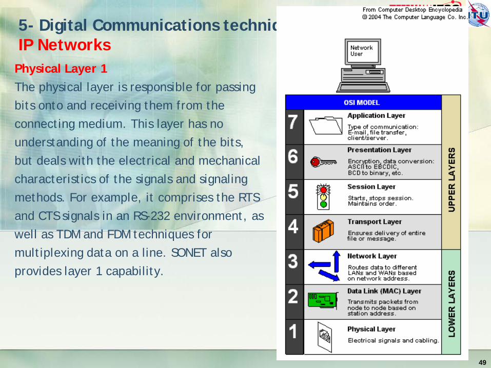
Physical Layer 1 The physical layer is responsible for passing bits onto and receiving them from the connecting medium. This layer has no understanding of the meaning of the bits, but deals with the electrical and mechanical characteristics of the signals and signaling methods. For example, it comprises the RTS and CTS signals in an RS-232 environment, as well as TDM and FDM techniques for multiplexing data on a line. SONET also provides layer 1 capability.
49

5- Digital Communications techniques IP Networks
The Protocol Stack
Using TCP/IP as a model, the sending application hands data to the transport layer, which breaks it up into the packets required by the network. It stores the sequence number and other data in its header. The network layer adds source and destination data in its header, and the data link layer adds station data in its header. On the other side, the corresponding layer reads and processes the headers and discards them.
50

5- Digital Communications techniques Compression
Analog Video Compression
In communications, data compression is helpful because it enables devices to store or transmit the same amount of data in fewer bits, thus making the transmission of the data faster.
A hardware circuit that converts analog video (NTSC, PAL, SECAM) into digital code and vice versa. The term may refer to only the A/D and D/A conversion, or it may include the compression technique for further reducing the signal
51

5- Digital Communications techniques Compression
Digital Video Compression
Hardware and/or software that compresses and decompresses a digital video signal. MPEG, Windows Media Video (WMV), H.264, VC-1 and
QuickTime are examples of codecs that compress and decompress digital video.
52

5- Digital Communications techniques VoiP
Definition
Referring to voice communications over the public Internet or any packet network employing the TCP/IP protocol suite. Specifically, VoIP operates in datagram mode, employing the Internet Protocol (IP) for addressing and routing, the User Datagram Protocol (UDP) for host-to-host data transfer between application programs, and the Real Time Transport Protocol (RTP) for end-to-end delivery services.
VoIP also typically employs sophisticated predictive compression algorithms, such as low delay code excited linear prediction (LD-CELP), to mitigate issues of latency and jitter over a packet-switched network.
53

5- Digital Communications techniques VoiP
Softphone based
VoIP providers may be entirely softphone based, which requires a computer, phone software and microphone and speakers (or headset) to make and receive calls. Usually free of cost if both sides are on the same service, softphones let users call any phone in the world from their laptops and an Internet connection. Per-minute charges apply to call a regular phone number, but calls from a regular phone may not be possible
54

5- Digital Communications techniques VoiP
Handset based
Regular phones can be used with many VoIP services by plugging them into an analog telephone adapter (ATA) provided by the VoIP provider or purchased from a third party. The ATA converts the phone to IP packets. IP phones can also be used that have built-in IP packet support.
55

5- Digital Communications techniques VoiP
IP Phone Built in VoIP
IP Phones can be directly connected to the IP network.
56

6- Modulation
In telecommunications, modulation is the process of conveying a message signal, for example a digital bit stream or an analog audio signal, inside another signal that can be physically transmitted. Modulation of a sine waveform is used to transform a baseband message signal to a passband signal, for example a radio-frequency signal (RF signal). In radio communications, cable TV systems or the public switched telephone network for instance, electrical signals can only be transferred over a limited passband frequency spectrum, with specific (non-zero) lower and upper cutoff frequencies.
57

6- Modulation
The three basic types of modulation are :
• Amplitude Shift Keying (ASK)
• Frequency Shift Keying (FSK)
• Phase Shift Keying (PSK)
All of these techniques varies a parameter of a sinusoid to represent the information which we wish to send. A sinusoid has 3 different parameters that can be varied. These are amplitude, phase and frequency
58

6- Modulation
Amplitude Modulation (AM)
Varying the voltage of a carrier or a direct current in order to transmit analog or digital data. Amplitude modulation (AM) is the oldest method of transmitting human voice electronically. In an analog telephone conversation, the voice waves on both sides are modulating the voltage of the direct current loop connected to them by the telephone company.
AM is also used for digital data. In quadrature amplitude modulation (QAM), both amplitude and phase modulation are used to create different binary states for transmission
59

6- Modulation
Amplitude Modulation (AM)
Vary the Amplitude
In AM modulation, the voltage (amplitude) of the carrier is varied by the incoming signal. In this example, the modulating wave implies an analog signal.
60

6- Modulation
Digital Amplitude Shift Keying (ASK)
For digital signals, amplitude shift keying (ASK) uses two voltage levels for 0 and 1 as in this example.
61

6- Modulation
Phase Shift Keying (PSK)
For digital signals, phase shift keying (PSK) uses two phases for 0 and 1 as in this example.
62

6- Modulation
Quadrature Phase Shift Keying (QPSK)
QPSK uses four phase angles to represent each two bits of input; however, the amplitude remains constant.
63

6- Modulation
Frequency Shift Keying (FSK)
FSK is a simple technique that uses two frequencies to represent 0 and 1.
64
6- Modulation
Digital 8QAM
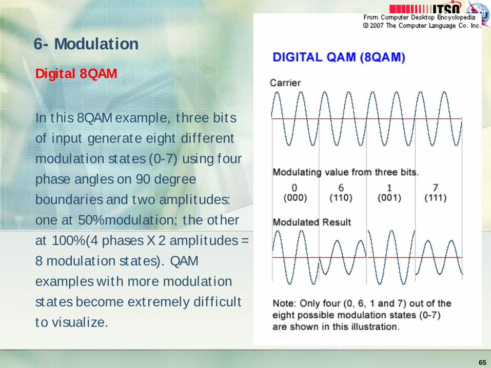
In this 8QAM example, three bits of input generate eight different modulation states (0-7) using four phase angles on 90 degree boundaries and two amplitudes: one at 50% modulation; the other at 100% (4 phases X 2 amplitudes = 8 modulation states). QAM examples with more modulation states become extremely difficult to visualize.
65

6- Modulation
Popular Modulation schemes used in satellite
Popular modulation types being used for satellite communications:
• Binary phase shift keying (BPSK);
• Quadrature phase shift keying (QPSK);
• 8PSK;
• Quadrature amplitude modulation (QAM), especially 16QAM.
66

7- Link Budget Analysis and Design
Satellite link budget objective
The first step in designing a satellite network is performance of a satellite link budget analysis. The link budget will determine what size antenna to use, SSPA or TWTA PA power requirements, link availability and bit error rate, and in general, the overall customer satisfaction with your work.
67

7- Link Budget Analysis and Design
Sample
68

7- Link Budget Analysis and Design
Understand Link budget
A satellite link budget is a listing of all the gains and losses that will affect the signal as it travels from the spacecraft to the ground station. There will be a similar list of gains and losses for the link from the ground station to the satellite. Link budgets are used by the system engineers to determine the specifications necessary to obtain the desired level of system performance. After the system has been built, the link budget is invaluable to the maintenance personnel for isolating the cause of degraded system performance.
69

7- Link Budget Analysis and Design
Understand Link budget
None of the components of a link is fixed, but instead will have some variation. The link budget must account for this. Typically the variables will be listed with a maximum and minimum value or with a nominal value plus a tolerance. The design engineer will allocate signal power to each variable so that the variations don't result in unacceptable signal fade. It is usually too expensive to build a system that will work with the worst case scenario for all variables, so it is the engineer's job to find an acceptable balance between cost and link availability. The maintenance engineer must also be aware of the variations so that he can properly differentiate between expected link degradation and a link failure.
70

7- Link Budget Analysis and Design
Understand Link budget
The satellite link is composed of many variables and it's important to understand when specific variables need to be included and when they can be ignored. In this tutorial we will discuss the most common variables and provide guidelines to help determine when they can be ignored.
The first variable in our link budget will be the spacecraft EIRP. This is the power output from the spacecraft. All other variables will be gains or losses that will be added or subtracted from the EIRP. Variations in the EIRP are normally pretty small and can be ignored by the maintenance engineer once the nominal EIRP is known. There may be small variations due to temperature and a larger change can be expected if the spacecraft configuration is changed, such as switching to a backup HPA.
71

7- Link Budget Analysis and Design
Understand Link budget
Path loss (Lpath) is the amount of signal attenuation due to the distance between the satellite and the ground station. This is the largest loss in the link. For example, the path loss for an S band signal from a geosyncronous satellite will be about 192 dB. Path loss varies with distance and frequency. The greater the distance, the greater the path loss. Higher frequencies suffer more loss than lower frequencies. Thus the path loss will be greater for a Ku band signal than for an S band signal at the same distance. For a geosyncronous satellite, the distance between the satellite and the ground station varies slightly over a 24 hour period. This variation may be important to the design engineer, but the maintenance engineer can usually work with a fixed average value for the path loss. For a low earth orbit (LEO) satellite the distance between the satellite and ground station is constantly changing. The maximum and minimum path loss will be important to both the design engineer and the maintenance engineer.
72

7- Link Budget Analysis and Design
Understand Link budget
The next loss we'll consider is the polarization loss (Lpol). The transmitting and receiving antennas are usually polarized to permit frequency reuse. Satellite links usually employ circular polarization, although linear polarization is occasionally used. In the case of circular polarization, the design engineer will use the axial ratio of the transmit and receive antennas to determine the maximum and minimum polarization loss. The maximum loss is usually small enough (0.3 dB typically) to be ignored by the maintenance engineer. There are, however, a couple of special cases that the maintenance engineer will need to keep in mind. If the ground antenna is capable of being configured for either LHCP or RHCP, a misconfiguration of the polarization will result in a significant loss, on the order of 20 dB or more. Also, polarization is affected by atmospheric conditions. If there is rain in the area, polarization loss may increase. More information on this is provided in the discussion of rain fade.
73

7- Link Budget Analysis and Design
Understand Link budget
Pointing loss (Lpoint) is the amount of signal loss due to inaccurate pointing of the antennas. To determine the expected amount of pointing loss, the design engineer will consider such things as antenna position encoder accuracy, resolution of position commands, and autotrack accuracy. The pointing accuracy of both the spacecraft antenna and the ground station antenna must be considered, although they may both be combined into one entry in the link budget. Pointing loss will usually be small, on the order of a few tenths of a dB. This is small enough for the maintenance engineer to ignore under normal circumstances. However, pointing loss is one of the most common causes of link failure. This is usually due to inaccurate commanded position of the antenna, but can also be caused by a faulty position encoder.
74

7- Link Budget Analysis and Design
Understand Link budget
Atmospheric loss (Latmos) is the amount of signal that is absorbed by the atmosphere as the signal travels from the satellite to the ground station. It varies with signal frequency and the signal path length through the atmosphere, which is related to the elevation angle between the ground station and the spacecraft. Theoretically, the amount of signal absorbed by rain could also be considered an atmospheric loss, but because rain fade can be quite large and unpredictable, it is given its own variable in the link budget. In general, atmospheric loss can be assumed to be less than 1 dB as long as the look angle elevation from the ground station is greater than 20 degrees.
75

7- Link Budget Analysis and Design
Understand Link budget
Rain fade is a unique entry in the link budget because it is derived from the system specification instead of being dependent on the natural elements of the link. The actual rain fade on a link can be quite large and unpredictable. It probably isn't practical to attempt to design a link that will perform to specifications under worst case rain conditions. Instead, the system specification might specify the amount of rain fade that the system must be able to tolerate and still meet the performance specifications. Specified rain fade is typically in the range of 6 dB. Therefore the link budget will list a maximum rain fade of 6 dB and a minimum of 0 dB. If the link is designed to this budget, it will have an additional 6 dB of link margin to compensate for a rain fade
76
7- Link Budget Analysis and Design
Understand Link budget
The variables we've discussed so far (EIRP, path loss, polarization loss, pointing loss, atmospheric loss, rain fade) are sufficient to define the signal power level at the ground station. The power would be shown by:
Power Level = EIRP - Lpath - Lpol - Lpoint - Latmos - rain fade
77

7- Link Budget Analysis and Design
Understand Link budget
The last two items we're going to include in our link budget are the ground station antenna and LNA. These two items aren't really variables, but are constants that the design engineer will select. Based on the power level indicated by the link budget and the carrier to noise requirement indicated by the system specs, the engineer will select an antenna/LNA pair that will amplify the signal sufficiently for further processing without adding more noise than the system spec allows. The antenna gain and the LNA noise will be combined into a single parameter called the "gain over noise temperature", or G/T . This will be the final entry in our link budget.
78

7- Link Budget Analysis and Design
Understand Link budget
The carrier to noise ratio C/N0 for the link can now be calculated as:
C/N0 = EIRP - Lpath - Lpol - Lpoint - Latmos - rain fade + G/T - Boltzmann's Constant
This completes the link budget for the space to ground link. A link budget for the ground to space link would be composed of the same variables. The variables would need to be updated for the uplink frequencies, the G/T would be the spacecraft G/T, and the ground station design engineer would then select the ground station EIRP required to meet system specs.
79

7- Link Budget Analysis and Design
Understand Link budget
Boltzmann's Constant (k) Amount of noise power contributed by 1 degree of temperature, kelvin.
k = 1.38 * 10^(-23) Watt-second/K
or
-228.6 dBw/Hz
80

7- Link Budget Analysis and Design
81

End of Day 3 course
82
Network Planning and Link Budget Analysis