Dax Router
356
Common Manual for DXMP Routers USER GUIDE
description
Common Manual for DXMP Routers USER GUIDE5HYLVLRQ 1LO 'DWHG 2FWREHU· Version: 1.0 Date: October’20031Dear Dax User, Congratulations!! You are now a proud owner of this DAX DXMP ROUTER. We are sure you will be delighted with the features and performance of your new product. And, the Dax support, if you need it. This DAX DXMP ROUTER has unique user-friendly features and benefits. And, is designed to increase the reliability and efficiency of your network. We at Dax have offered th
Transcript of Dax Router
Common Manual for DXMP Routers
USER GUIDE

1
Version: 1.0
Date: October’2003
5HYLVLRQ1LO�'DWHG�2FWREHU·�����
2
Dear Dax User, Congratulations!! You are now a proud owner of this DAX DXMP ROUTER. We are sure you will be delighted with the features and performance of your new product. And, the Dax support, if you need it. This DAX DXMP ROUTER has unique user-friendly features and benefits. And, is designed to increase the reliability and efficiency of your network. We at Dax have offered the highest level of pre/post sales support in India for 15 years and are committed to providing you with International quality, Indian market savvy products. This DAX DXMP ROUTER is a reflection of that commitment. It is with this confidence that we promise you a 3 Years Carry-in warranty of which Instant Replacement Anywhere is provided during the first year of warranty. Please contact me (or any Dax Office) if and when you need us, we will endeavor to win your confidence too. “Happy Daxing”
Sujit Country Manager - Dax
3
FCC Warning This equipment has been tested and found to comply with the limits of a Class B computing device, pursuant to Part 15 of the FCC rules. These limits are designed to provide reasonable protection against harmful interference in a residential installation. This equipment generates, uses and can radiate radio frequency energy and, if not installed and used in accordance with the instructions, may cause harmful interference to radio communications. If you suspect this product is causing interference, turn your computer ON and OFF while your radio or TV is showing interference. If the interference disappears when you turn the computer OFF and reappears when you turn the computer ON, then something in the computer is causing interference. You can try to correct the interference by one or more of the following measures: 1. Reorient/Relocate the receiving antenna.
2. Increase the separation between the equipment and receiver.
3. Connect the equipment into an outlet on a circuit difference from that to which the receiver is connected.
4. Ensure that all expansion slots (on the back or side of the computer) are covered. Also ensure that all metal retaining brackets are tightly attached to the computer.
CE Marking Warning
This is a Class A product. In a domestic environment this product may cause radio interference in which case the user may be required to take adequate measures.
4
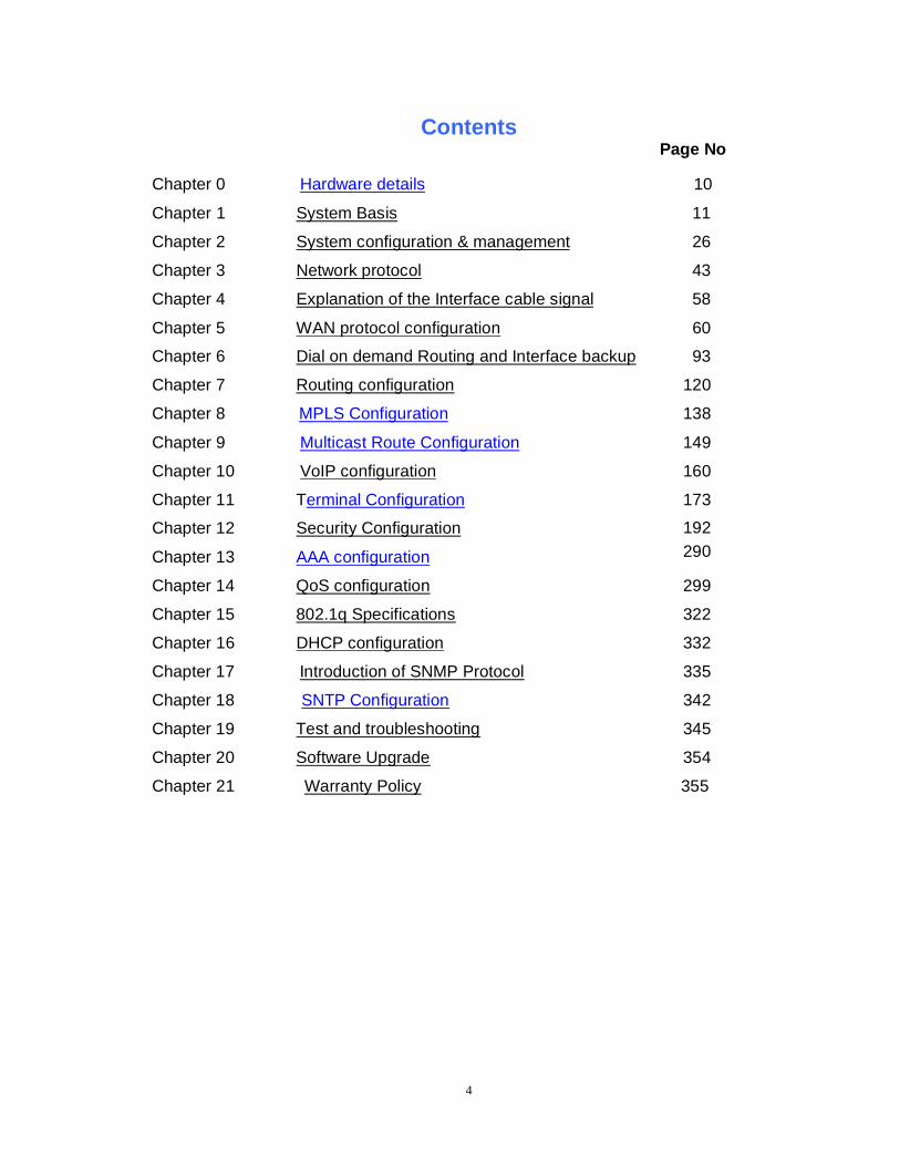
Contents Page No
Chapter 0 Hardware details 10
Chapter 1 System Basis 11
Chapter 2 System configuration & management 26
Chapter 3 Network protocol 43
Chapter 4 Explanation of the Interface cable signal 58
Chapter 5 WAN protocol configuration 60
Chapter 6 Dial on demand Routing and Interface backup 93
Chapter 7 Routing configuration 120
138 Chapter 8 MPLS Configuration
Chapter 9 Multicast Route Configuration
Chapter 10 VoIP configuration
149
160
Chapter 11
Chapter 12
Chapter 13
Terminal Configuration
Security Configuration
AAA configuration
173
192 290
Chapter 14 QoS configuration 299
Chapter 15 802.1q Specifications 322
Chapter 16 DHCP configuration 332
335 Chapter 17 Introduction of SNMP Protocol
Chapter 18 SNTP Configuration 342
Chapter 19 Test and troubleshooting 345
Chapter 20 Software Upgrade 354
Chapter 21 Warranty Policy 355
5
1. Introduction DAX-MAIPU modular router series intends to provide a set of cost-effective networking solutions to meet the users’ need for versatility, integration and high performance. DAX-MAIPU router supports applications as follows:
• Computer network interconnection • Multiservice data integration • Dialing-up and dial-up at branch offices • Access to Internet and Extranet
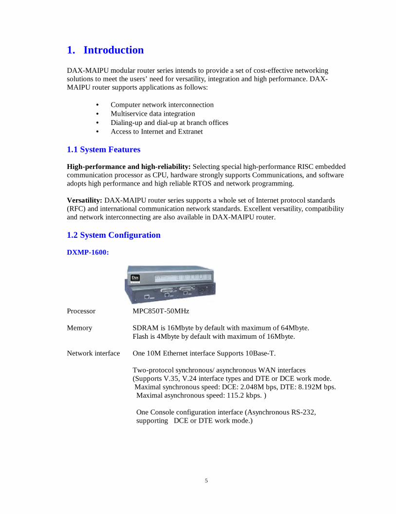
1.1 System Features High-performance and high-reliability: Selecting special high-performance RISC embedded communication processor as CPU, hardware strongly supports Communications, and software adopts high performance and high reliable RTOS and network programming. Versatility: DAX-MAIPU router series supports a whole set of Internet protocol standards (RFC) and international communication network standards. Excellent versatility, compatibility and network interconnecting are also available in DAX-MAIPU router. 1.2 System Configuration DXMP-1600: Processor MPC850T-50MHz Memory SDRAM is 16Mbyte by default with maximum of 64Mbyte.
Flash is 4Mbyte by default with maximum of 16Mbyte.
Network interface One 10M Ethernet interface Supports 10Base-T. Two-protocol synchronous/ asynchronous WAN interfaces (Supports V.35, V.24 interface types and DTE or DCE work mode. Maximal synchronous speed: DCE: 2.048M bps, DTE: 8.192M bps.
Maximal asynchronous speed: 115.2 kbps. )
One Console configuration interface (Asynchronous RS-232, supporting DCE or DTE work mode.)
6
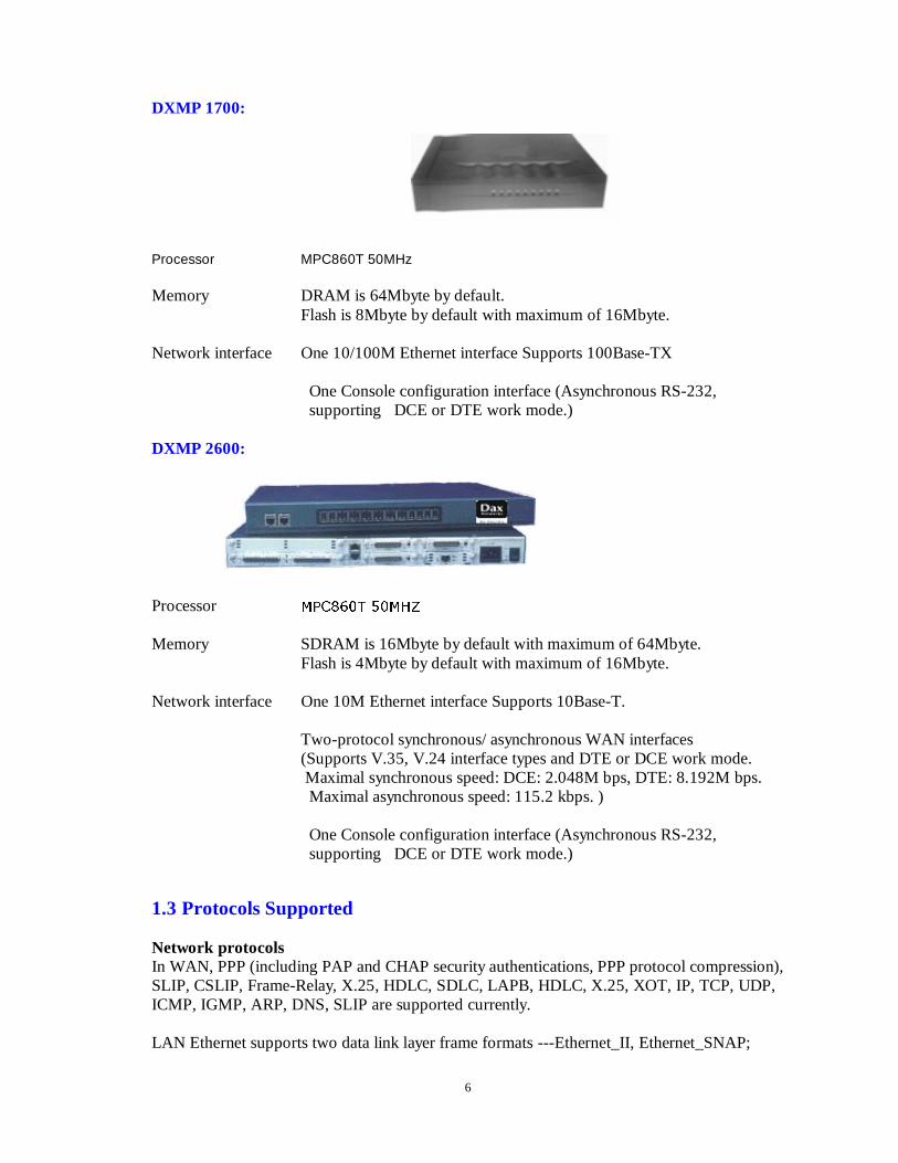
DXMP 1700:
Processor MPC860T 50MHz
Memory DRAM is 64Mbyte by default. Flash is 8Mbyte by default with maximum of 16Mbyte.
Network interface One 10/100M Ethernet interface Supports 100Base-TX
One Console configuration interface (Asynchronous RS-232, supporting DCE or DTE work mode.)
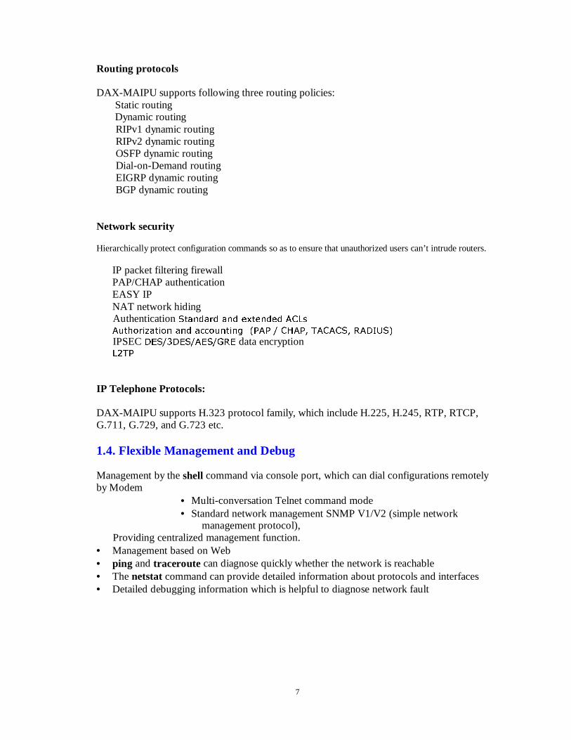
DXMP 2600:
Processor 03&���7 ��0+=
Memory SDRAM is 16Mbyte by default with maximum of 64Mbyte. Flash is 4Mbyte by default with maximum of 16Mbyte.
Network interface One 10M Ethernet interface Supports 10Base-T. Two-protocol synchronous/ asynchronous WAN interfaces (Supports V.35, V.24 interface types and DTE or DCE work mode. Maximal synchronous speed: DCE: 2.048M bps, DTE: 8.192M bps.
Maximal asynchronous speed: 115.2 kbps. )
One Console configuration interface (Asynchronous RS-232, supporting DCE or DTE work mode.)
1.3 Protocols Supported Network protocols In WAN, PPP (including PAP and CHAP security authentications, PPP protocol compression), SLIP, CSLIP, Frame-Relay, X.25, HDLC, SDLC, LAPB, HDLC, X.25, XOT, IP, TCP, UDP, ICMP, IGMP, ARP, DNS, SLIP are supported currently. LAN Ethernet supports two data link layer frame formats ---Ethernet_II, Ethernet_SNAP;
7
Routing protocols DAX-MAIPU supports following three routing policies:
Static routing Dynamic routing
RIPv1 dynamic routing RIPv2 dynamic routing OSFP dynamic routing Dial-on-Demand routing EIGRP dynamic routing BGP dynamic routing
Network security Hierarchically protect configuration commands so as to ensure that unauthorized users can’t intrude routers.
IP packet filtering firewall PAP/CHAP authentication EASY IP NAT network hiding
Authentication 6WDQGDUG DQG H[WHQGHG $&/V
$XWKRUL]DWLRQ DQG DFFRXQWLQJ �3$3 � &+$3� 7$&$&6� 5$',86�
IPSEC '(6��'(6�$(6�*5( data encryption /�73
IP Telephone Protocols: DAX-MAIPU supports H.323 protocol family, which include H.225, H.245, RTP, RTCP, G.711, G.729, and G.723 etc.
1.4. Flexible Management and Debug Management by the shell command via console port, which can dial configurations remotely by Modem
• Multi-conversation Telnet command mode • Standard network management SNMP V1/V2 (simple network
management protocol), Providing centralized management function. • Management based on Web • ping and traceroute can diagnose quickly whether the network is reachable • The netstat command can provide detailed information about protocols and interfaces • Detailed debugging information which is helpful to diagnose network fault
8
2. System Installation 2.1 Installation Preparation Requirement of Power Supply
Power input: 180~240V, 50/60Hz
3Rwer consumption: 20W±10%
DAX-MAIPU routers must be used indoors; the requirement of environment indoors is as follows:
· Temperature range: 0 ~ 40 degree C · Humidity: 10 ~90% non-condensing.
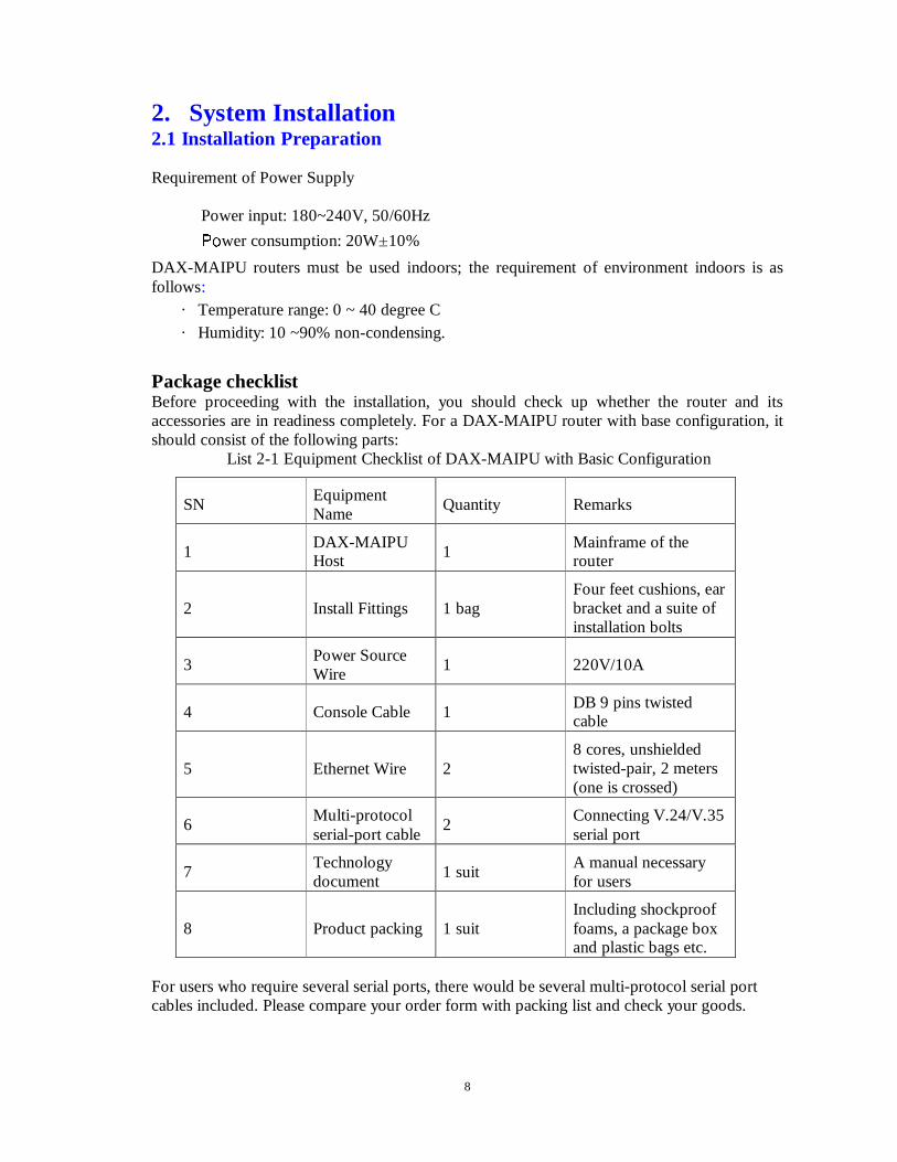
Package checklist Before proceeding with the installation, you should check up whether the router and its accessories are in readiness completely. For a DAX-MAIPU router with base configuration, it should consist of the following parts:
List 2-1 Equipment Checklist of DAX-MAIPU with Basic Configuration
SN Equipment Name
Quantity Remarks
1 DAX-MAIPU Host 1
Mainframe of the router
2 Install Fittings 1 bag Four feet cushions, ear bracket and a suite of installation bolts
3 Power Source Wire
1 220V/10A
4 Console Cable 1 DB 9 pins twisted cable
5 Ethernet Wire 2 8 cores, unshielded twisted-pair, 2 meters (one is crossed)
6 Multi-protocol serial-port cable
2 Connecting V.24/V.35 serial port
7 Technology document
1 suit A manual necessary for users
8 Product packing 1 suit Including shockproof foams, a package box and plastic bags etc.
For users who require several serial ports, there would be several multi-protocol serial port cables included. Please compare your order form with packing list and check your goods.
9
2.2 Hardware Installation 2.2.1 Illustration of Interfaces The sketch of rear panel interface of DAX-MAIPU, in which there are: SERIAL (The actual interface modules depend on the interfacing modes)
CONSOLE (RJ45) ¦¦ Console Port
ETHERNET 0 (RJ45)¦¦ 10M Ethernet
AC 220V ¦¦ Alternating input current (220V)
ON/OFF ¦¦ Power switch
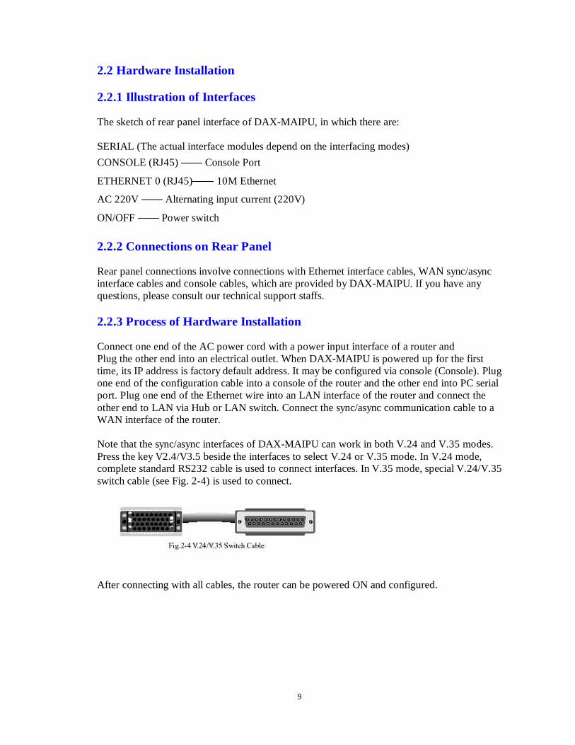
2.2.2 Connections on Rear Panel Rear panel connections involve connections with Ethernet interface cables, WAN sync/async interface cables and console cables, which are provided by DAX-MAIPU. If you have any questions, please consult our technical support staffs. 2.2.3 Process of Hardware Installation Connect one end of the AC power cord with a power input interface of a router and Plug the other end into an electrical outlet. When DAX-MAIPU is powered up for the first time, its IP address is factory default address. It may be configured via console (Console). Plug one end of the configuration cable into a console of the router and the other end into PC serial port. Plug one end of the Ethernet wire into an LAN interface of the router and connect the other end to LAN via Hub or LAN switch. Connect the sync/async communication cable to a WAN interface of the router. Note that the sync/async interfaces of DAX-MAIPU can work in both V.24 and V.35 modes. Press the key V2.4/V3.5 beside the interfaces to select V.24 or V.35 mode. In V.24 mode, complete standard RS232 cable is used to connect interfaces. In V.35 mode, special V.24/V.35 switch cable (see Fig. 2-4) is used to connect.
After connecting with all cables, the router can be powered ON and configured.
10
Chapter 1 System Basis This chapter mainly describes the basic concepts of InfoExpress IOS system in the Dax-Maipu router, such as the InfoExpress system mode, the preparation of configuration environment, a command line interface and so on. Main contents of this chapter are as follows:
�5RXWHU &RQILJXUDWLRQ PRGH �&RPPDQG UXQ PRGH �&RQVWUXFWLQJ WKH FRQILJXUDWLRQ HQYLURQPHQW �&RPPDQG OLQH LQWHUIDFH
Section 1 Router Configuration Mode
Dax-Maipu router provides users with four typical configuration modes: � Use the command shell to configure through the console interface; � Configure through Telnet and remote login;
� Configure through SNMP network management system.
Section 2 Command line Mode InfoExpress IOS of DAX-MAIPU router specially provides a subsystem dealing with commands for management and execution of system commands, which is called shell . The main functions of shell are as follows: � Register of system commands � User edit of system configuring commands � 6\QWD[ SDUVLQJ RI FRPPDQGV LQSXW E\ XVHUV �WKURXJK LQWHUIDFH console or Telnet link) � ([HFXWLRQ RI V\VWHP &RPPDQG When a user configures router through the command shell , the system provides many kinds of run modes for the execution of the command. Each command mode respectively supports the special InfoExpress IOS configuring command. Accordingly this attains the aim of hierarchy protection of system, and ensures there be no unauthorized access to the system.
The Shell subsystem presently provides the following modes for running the configuring commands, and each different mode is corresponding with a different system prompt that is employed to tell users in which mode he is presently. These modes are as follows:
� Common user mode (User EXEC) � 3ULYLOHJHG XVHU PRGH (Privileged EXEC) � Global configuration mode (Global configuration) � Interface configuration mode (Interface configuration) � Route configuration mode (route configuration) � File system configuration mode (file system configuration)
� Access list configuration mode (access list configuration) � Voice-port configuration mode (voice-port configuration) � Dial-peer configuration mode (dial-peer configuring) � Encryption transform configuration mode (crypto transform-set configuration) � Encryption mapping configuration mode(crypto map configuration) � IKE policy configuration mode (isakmp configuration) � Pub key chain configuration mode (pubkey-chain configuration) � Pub key configuration mode (pubkey-key configuration) � DHCP configuration mode (dhcp configuration)
Other configuration modes will be introduced in relevant chapters.
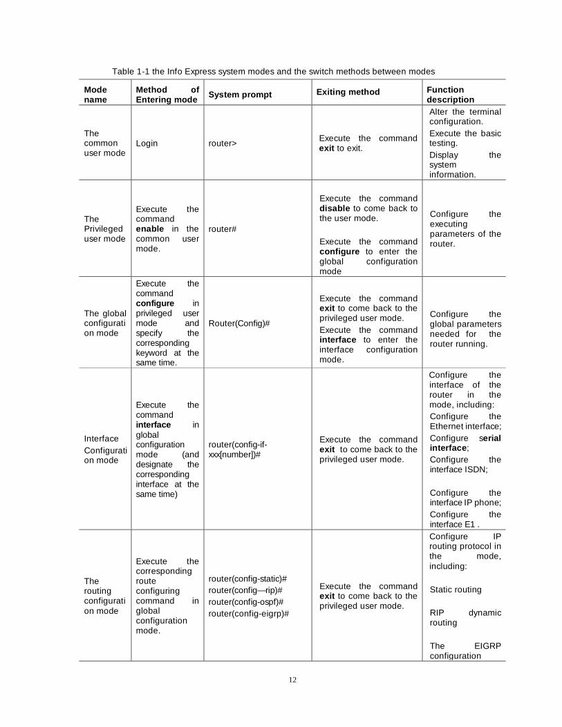
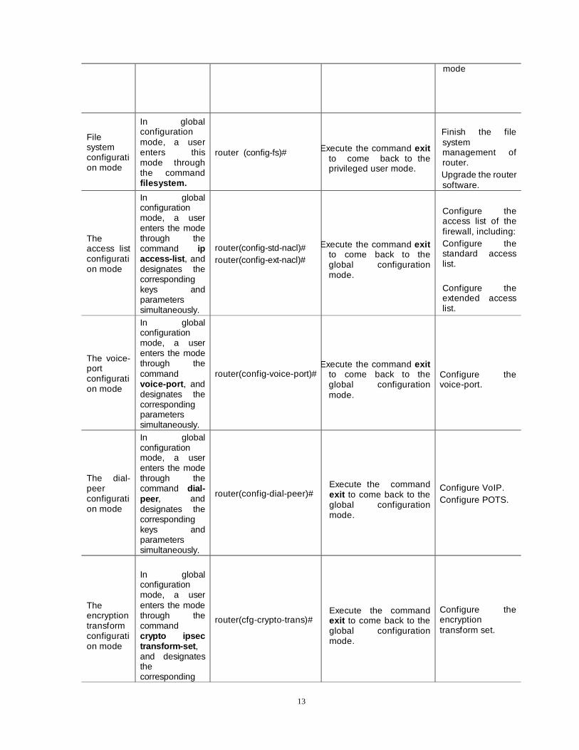
Table 1-1 describes methods of entering different command modes and the switch between different modes.

11
12
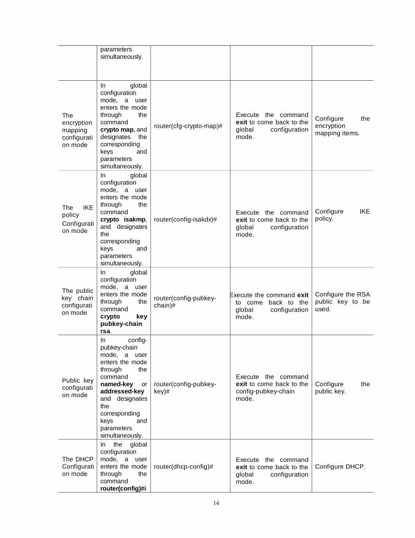
Table 1-1 the Info Express system modes and the switch methods between modes
Mode name
Method of Entering mode System prompt Exiting method Function
description
The common user mode
Login router> Execute the command exit to exit.
Alter the terminal configuration. Execute the basic testing. Display the system information.
The Privileged user mode
Execute the command enable in the common user mode.
router#
Execute the command disable to come back to the user mode.
Execute the command configure to enter the global configuration mode
Configure the executing parameters of the router.
The global configuration mode
Execute the command configure in privileged user mode and specify the corresponding keyword at the same time.
Router(Config)#
Execute the command exit to come back to the privileged user mode. Execute the command interface to enter the interface configuration mode.
Configure the global parameters needed for the router running.
Interface Configuration mode
Execute the command interface in global configuration mode (and designate the corresponding interface at the same time)
router(config-if-xxx[number])#
Execute the command exit to come back to the privileged user mode.
Configure the interface of the router in the mode, including: Configure the Ethernet interface; Configure serial interface ; Configure the interface ISDN;
Configure the interface IP phone; Configure the interface E1 .
The routing configuration mode
Execute the corresponding route configuring command in global configuration mode.
router(config-static)# router(config—rip)# router(config-ospf)# router(config-eigrp)#
Execute the command exit to come back to the privileged user mode.
Configure IP routing protocol in the mode, including:
Static routing
RIP dynamic routing
The EIGRP configuration
13
mode
File system configuration mode
In global configuration mode, a user enters this mode through the command filesystem.
router (config-fs)# Execute the command exit to come back to the privileged user mode.
Finish the file system management of router.
Upgrade the router software.
The access list configuration mode
In global configuration mode, a user enters the mode through the command ip access-list , and designates the corresponding keys and parameters simultaneously.
router(config-std-nacl)# router(config-ext-nacl)#
Execute the command exit to come back to the global configuration mode.
Configure the access list of the firewall, including: Configure the standard access list. Configure the extended access list.
The voice-port configuration mode
In global configuration mode, a user enters the mode through the command voice-port , and designates the corresponding parameters simultaneously.
router(config-voice-port)# Execute the command exit
to come back to the global configuration mode.
Configure the voice-port.
The dial-peer configuration mode
In global configuration mode, a user enters the mode through the command dial-peer, and designates the corresponding keys and parameters simultaneously.
router(config-dial-peer)# Execute the command exit to come back to the global configuration mode.
Configure VoIP. Configure POTS.
The encryption transform configuration mode
In global configuration mode, a user enters the mode through the command crypto ipsec transform-set , and designates the corresponding
router(cfg-crypto-trans)# Execute the command exit to come back to the global configuration mode.
Configure the encryption transform set.
14
parameters simultaneously.
The encryption mapping configuration mode
In global configuration mode, a user enters the mode through the command crypto map , and designates the corresponding keys and parameters simultaneously.
router(cfg-crypto-map)#
Execute the command exit to come back to the global configuration mode.
Configure the encryption mapping items.
The IKE policy Configuration mode
In global configuration mode, a user enters the mode through the command crypto isakmp , and designates the corresponding keys and parameters simultaneously.
router(config-isakdx)# Execute the command exit to come back to the global configuration mode.
Configure IKE policy.
The public key chain configuration mode
In global configuration mode, a user enters the mode through the command crypto key pubkey-chain rsa .
router(config-pubkey-chain)#
Execute the command exit to come back to the global configuration mode.
Configure the RSA public key to be used.
Public key configuration mode
In config-pubkey-chain mode, a user enters the mode through the command named-key or addressed-key and designates the corresponding keys and parameters simultaneously.
router(config-pubkey-key)#
Execute the command exit to come back to the config-pubkey-chain mode.
Configure the public key.
The DHCP Configuration mode
In the global configuration mode, a user enters the mode through the command router(config)#i
router(dhcp-config)# Execute the command exit to come back to the global configuration mode.
Configure DHCP.
15
p dhcp pool, and designates the corresponding key words and parameters simultaneously.
Note:
The word router is the default system name of a router when it leaves factory. Users can rename the system name by executing the command hostname in the global configuration mode, and the alteration can go into effect instantly.
Section 3 Constructing the Configuration Environment Users can use the command line provided by a router by means of four approaches. These approaches are introduced respectively as follows:
1. Configuring a Router through the configuration interface (Console) It needs the following steps to connect with a terminal and configure the router through the port Console : Choosing a terminal The terminal can be a standard one with RS-232 serial port or a common PC, and the later is used more frequently. If making configuration from the remote end, you need two more modems. When it can be affirmed that at least one of the router and the terminal be shut down
ÚÚÚÚÚÚÚÚÚÚÚÚÚÚÚÚÚÚÚÚÚÚÚÚÚÚÚÚÚÚÚÚÚÚÚÚÚÚÚÚÚÚÚÚÚ
, it is through the configuration of the cable that the serial port RS-232 can be connected with the port Console of the router.
Power the terminal, configure the communicating parameters of the terminal: 9600bps Baud rate, 8 data bits, no parity, 1 stop bit, and no flow control, choose VT100 as the type of terminal. If it is a PC, which runs Win95/98/2000/NT operating system, then runs Hyper Terminal program, and the serial port parameters of HyperTerminal program is set according to above parameters. It can be interpreted by the following example of the HyperTerminal program running in Windows NT:
The example of configuring communication parameters of HyperTerminal program:
Creating a connection
Choosing a name for the connection --- DXMP ROUTER
Or choosing an arbitrary name Choosing a windows icon for the created connection
Choosing serial communication port Choosing COM1 or COM2 according to the connected serial port
Configuring parameters of serial communication port (Figure 1-5)
Baud ratio --- 9600bps
Data bit --- 8 bits
parity checking ---no Stop bit----1 bit
Flow control---no
16
Power the router, and press the key enters on the terminal, then a prompt “router> ”will be displayed on the terminal and the router can be configured.
2. Making configuration through the LINE port of 56/336modem module If the 56/336modem module has been configured in the router, the DIP dial-up switch of the module can be used to configure the working mode of the port LINE .The usage of the switch DIP can be shown in the table 1-2:
Configuring the DIP switch Choosing mode
1 2
Interpretation
1. 56/336MODEM mode OFF OFF LINE port is used as the interface of the inside 56/336MODEM.
2. Console port mode ON OFF The LINE port is used as a CONSOLE port, and the router can be configured through the remote dial-up login.
Table 1-2 Usages of DIP dial-up switch in the 56/336modem module 3. Configuring a Router through Telnet
If the IP address of each interface in the router has been configured right, then Telnet can be used to log in the router through LAN or WAN and the router can be configured.
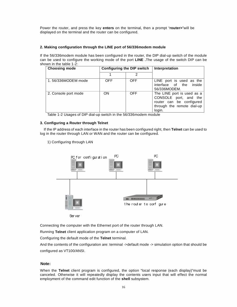
1) Configuring through LAN
3& I RU FRQI L JXU DW L RQ 3& 3&
6HU YHU
W KH U RXW HU W R FRQI L JXU H
Connecting the computer with the Ethernet port of the router through LAN.
Running Telnet client application program on a computer of LAN.
Configuring the default mode of the Telnet terminal.
And the contents of the configuration are: terminal ->default mode -> simulation option that should be
configured as VT100/ANSI.
Note:
When the Telnet client program is configured, the option “local response (each display)”must be canceled. Otherwise it will repeatedly display the contents users input that will effect the normal employment of the command edit function of the shell subsystem.
17
Keying in the IP address of the router, and establishing Telnet connection with the router; Setting the host name as the IP address of the router: 128.255.255.1 Configuring port as Telnet (23);
Configuring the type of terminal as ANSI;
The other operations are the same as the configuration through the console interface.
2) Configuring through WAN:
Connecting the computer for configuration with remote router to configure through LAN
Running Telnet client program application program on the local computer for configuration
The following steps are the same as that of configuration through LAN
/RFDO
U RXW HU
/$1
5RXW HU ZDL W L QJ I RU
FRQI L JXU DW L RQ
6HU YHU
6\QFKU RQRXV�
DV\QFKU RQRXV SRU W 6\QFKU RQRXV�
DV\QFKU RQRXV SRU W
:$1
/$1
3& 3& 3&
3& I RU
FRQI L JXU DW L RQ
&RQI L JXU L QJ W KH U HPRW H U RXW HU
W KU RXJK 3& I RU FRQI L JXU DW L RQ L Q /$1
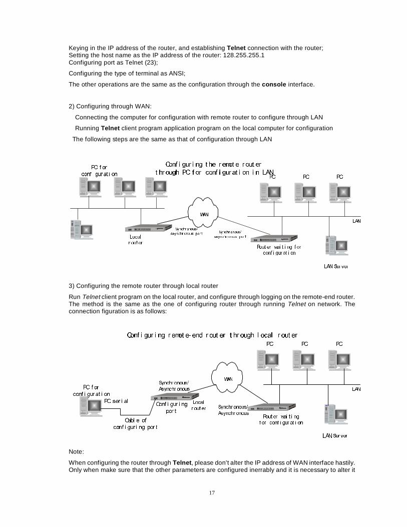
3) Configuring the remote router through local router
Run Telnet client program on the local router, and configure through logging on the remote-end router. The method is the same as the one of configuring router through running Telnet on network. The connection figuration is as follows:
/RFDO
U RXW HU
/$1
5RXW HU ZDL W L QJ
I RU FRQI L JXU DW L RQ
6HU YHU
6\QFKU RQRXV�
$V\QFKU RQRXV
6\QFKU RQRXV�
$V\QFKU RQRXV
:$1
/$1
3& 3& 3&
3& I RU
FRQI L JXUDW L RQ
3& VHU L DO
&DEO H RI
FRQI L JXU L QJ SRU W
&RQI L JXU L QJ
SRU W
&RQI L JXU L QJ U HPRW H� HQG U RXW HU W KU RXJK O RFDO U RXW HU
Note:
When configuring the router through Telnet , please don’t alter the IP address of WAN interface hastily. Only when make sure that the other parameters are configured inerrably and it is necessary to alter it
18
can you do. After the address is altered, Telnet may interrupt the connection. So the connection must be established again after the new IP address is input.
If users log in Dax-Maipu through Linux, then the configuration should be made as follows: Firstly, input the user name and password and enter Linux system;
Run telnet client program in shell environment of Linux system to log in the router. And the command is as follows:
telnet 128.255.255.1
After the command is executed, the output is as follows:
Trying 128.255.255.1...
Connected to 128.255.255.1
Escape character is '^]'.
Display the system prompt of the router:
router>
Press the combination key ^] to come back to the prompt of telnet program:
telnet>
Execute the command to cancel the local binary mode
telnet> unset binary
Already in network ascii mode with remote host.
router>
Only through the above operations, can the shell system command edit environment of the router work normally.
If users log in the router through other type of Telnet client program, and the command edit environment works abnormally, please configure the Telnet client program according to the above specification. Section 4 Command Line Interfaces
The command line interface is an interactive people-computer interface provided by the shell subsystem for users to configure and use the router. Users can input and edit commands to finish the corresponding configuration tasks through the command line interface. At the same time, they can also examine the system information and see the running status of the system through the interface.
The command line interface provides users with the following functions:
Manage the help information of system;
Input and edit of system commands;
Manage history commands of the interface;
Manage the terminal displaying system.
1. The on-line help of command line
The command line provide the following kinds of on-line helps:
help
full help
partial help
19
By means of the above help methods, users can get various kinds of help information, and different kinds of examples are as follows:
1) In any kind of command mode, you can get simple description about the help system after keying in help .
router>help
Help may be requested at any point in a command by entering
a question mark '?'. If nothing matches, the help list will be empty and you must backup until entering a '?' shows the available options.
Two styles of help are provided:
1. Full help is available when you are ready to enter a
command argument (e.g. 'show ?') and describes each possible argument.
2. Partial help is provided when an abbreviated argument is entered and you want to know what arguments match the input
(e.g. 'show pr?'.)
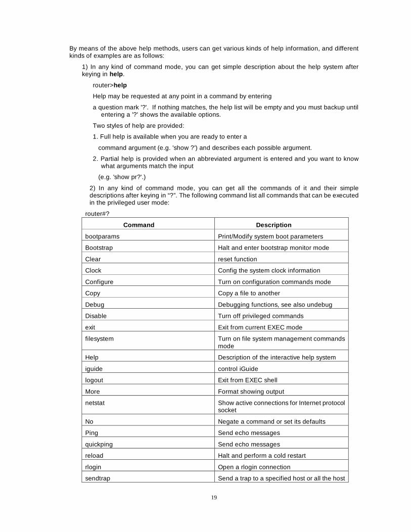
2) In any kind of command mode, you can get all the commands of it and their simple descriptions after keying in “?”. The following command list all commands that can be executed in the privileged user mode:
router#?
Command Description
bootparams Print/Modify system boot parameters
Bootstrap Halt and enter bootstrap monitor mode
Clear reset function
Clock Config the system clock information
Configure Turn on configuration commands mode
Copy Copy a file to another
Debug Debugging functions, see also undebug
Disable Turn off privileged commands
exit Exit from current EXEC mode
filesystem Turn on file system management commands mode
Help Description of the interactive help system
iguide control iGuide
logout Exit from EXEC shell
More Format showing output
netstat Show active connections for Internet protocol socket
No Negate a command or set its defaults
Ping Send echo messages
quickping Send echo messages
reload Halt and perform a cold restart
rlogin Open a rlogin connection
sendtrap Send a trap to a specified host or all the host
20
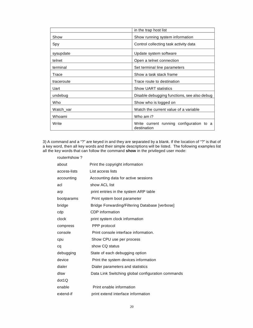
in the trap host list
Show Show running system information
Spy Control collecting task activity data
sysupdate Update system software
telnet Open a telnet connection
terminal Set terminal line parameters
Trace Show a task stack frame
traceroute Trace route to destination
Uart Show UART statistics
undebug Disable debugging functions, see also debug
Who Show who is logged on
Watch_var Watch the current value of a variable
Whoami Who am i?
Write Write current running configuration to a destination
3) A command and a “?” are keyed in and they are separated by a blank. If the location of “?” is that of a key word, then all key words and their simple descriptions will be listed. The following examples list all the key words that can follow the command show in the privileged user mode:
router#show ?
about Print the copyright information
access-lists List access lists
accounting Accounting data for active sessions
acl show ACL list
arp print entries in the system ARP table
bootparams Print system boot parameter
bridge Bridge Forwarding/Filtering Database [verbose]
cdp CDP information
clock print system clock information
compress PPP protocol
console Print console interface information.
cpu Show CPU use per process
cq show CQ status
debugging State of each debugging option
device Print the system devices information
dialer Dialer parameters and statistics
dlsw Data Link Switching global configuration commands
dot1Q
enable Print enable information
extend-if print extend interface information
21
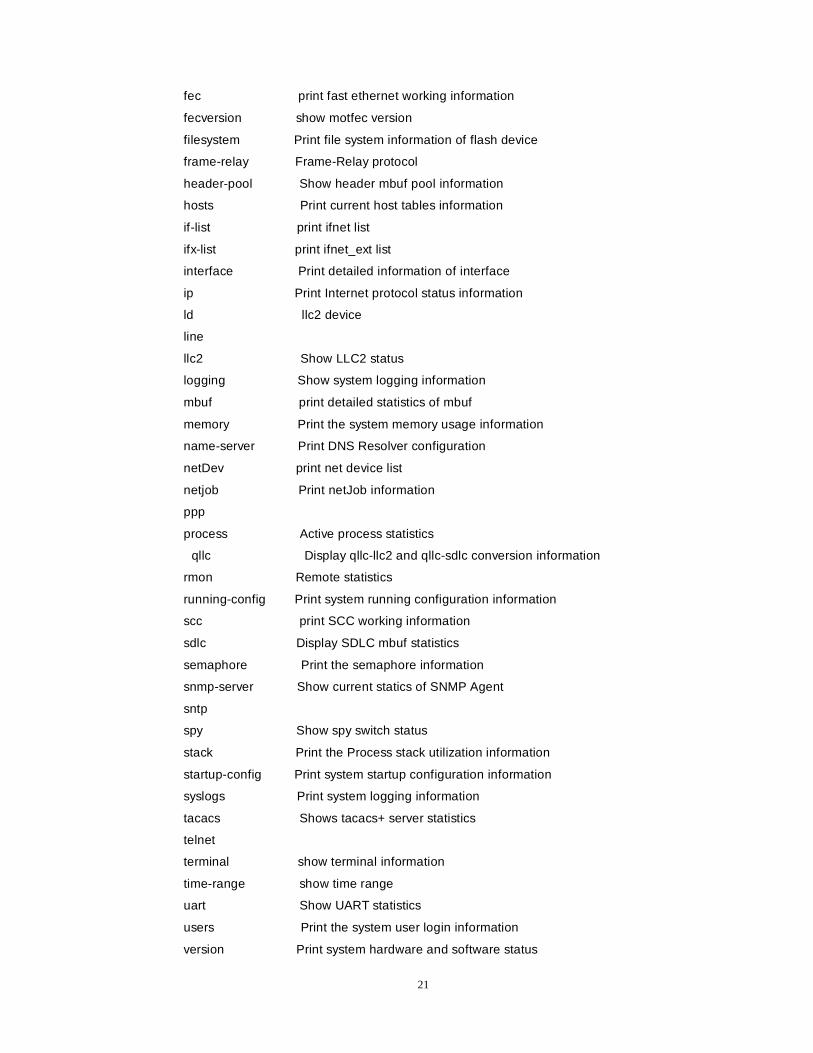
fec print fast ethernet working information
fecversion show motfec version
filesystem Print file system information of flash device
frame-relay Frame-Relay protocol
header-pool Show header mbuf pool information
hosts Print current host tables information
if-list print ifnet list
ifx-list print ifnet_ext list
interface Print detailed information of interface
ip Print Internet protocol status information
ld llc2 device
line
llc2 Show LLC2 status
logging Show system logging information
mbuf print detailed statistics of mbuf
memory Print the system memory usage information
name-server Print DNS Resolver configuration
netDev print net device list
netjob Print netJob information
ppp
process Active process statistics
qllc Display qllc-llc2 and qllc-sdlc conversion information
rmon Remote statistics
running-config Print system running configuration information
scc print SCC working information
sdlc Display SDLC mbuf statistics
semaphore Print the semaphore information
snmp-server Show current statics of SNMP Agent
sntp
spy Show spy switch status
stack Print the Process stack utilization information
startup-config Print system startup configuration information
syslogs Print system logging information
tacacs Shows tacacs+ server statistics
telnet
terminal show terminal information
time-range show time range
uart Show UART statistics
users Print the system user login information
version Print system hardware and software status
22
wfq show WFQ status
x25 X.25 information
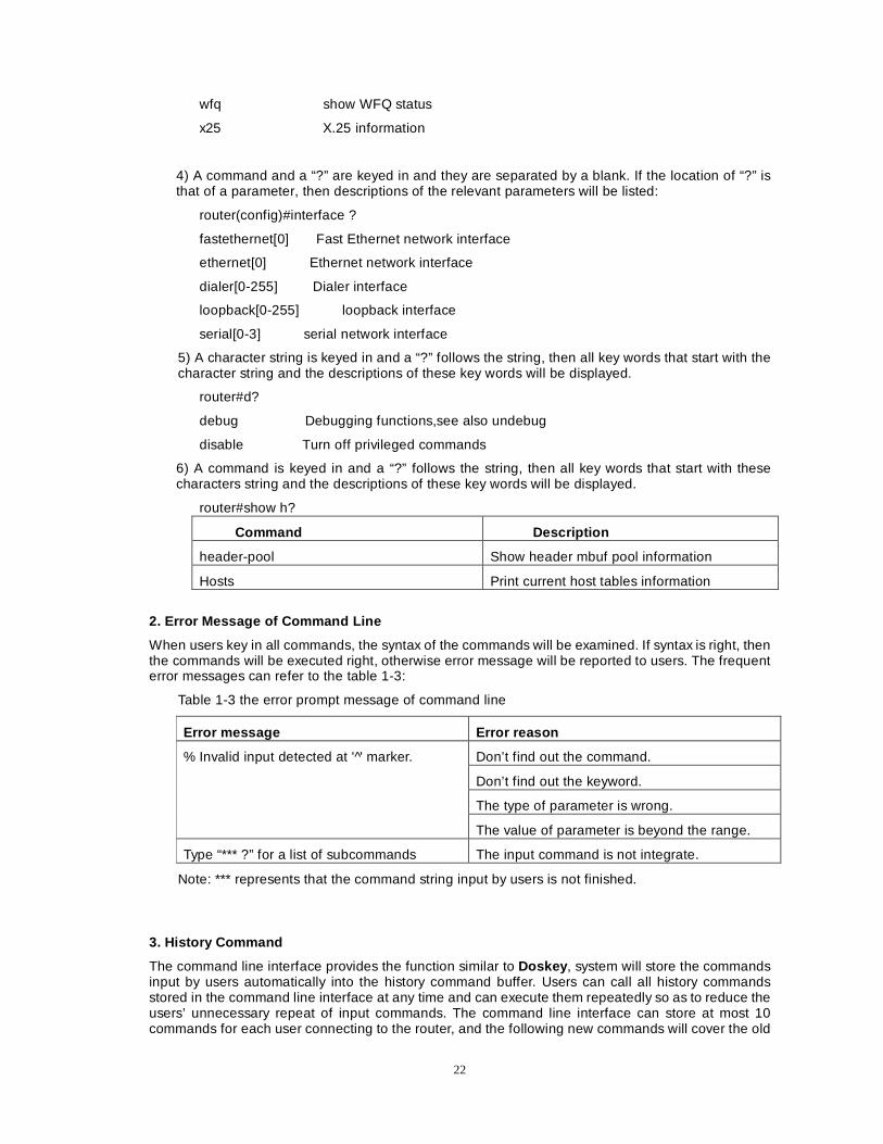
4) A command and a “?” are keyed in and they are separated by a blank. If the location of “?” is that of a parameter, then descriptions of the relevant parameters will be listed:
router(config)#interface ?
fastethernet[0] Fast Ethernet network interface
ethernet[0] Ethernet network interface
dialer[0-255] Dialer interface
loopback[0-255] loopback interface
serial[0-3] serial network interface
5) A character string is keyed in and a “?” follows the string, then all key words that start with the character string and the descriptions of these key words will be displayed.
router#d?
debug Debugging functions,see also undebug
disable Turn off privileged commands
6) A command is keyed in and a “?” follows the string, then all key words that start with these characters string and the descriptions of these key words will be displayed.
router#show h?
Command Description
header-pool Show header mbuf pool information
Hosts Print current host tables information
2. Error Message of Command Line
When users key in all commands, the syntax of the commands will be examined. If syntax is right, then the commands will be executed right, otherwise error message will be reported to users. The frequent error messages can refer to the table 1-3:
Table 1-3 the error prompt message of command line
Error message Error reason
Don’t find out the command.
Don’t find out the keyword.
The type of parameter is wrong.
% Invalid input detected at ' '̂ marker.
The value of parameter is beyond the range.
Type “*** ?” for a list of subcommands The input command is not integrate.
Note: *** represents that the command string input by users is not finished.
3. History Command
The command line interface provides the function similar to Doskey , system will store the commands input by users automatically into the history command buffer. Users can call all history commands stored in the command line interface at any time and can execute them repeatedly so as to reduce the users’ unnecessary repeat of input commands. The command line interface can store at most 10 commands for each user connecting to the router, and the following new commands will cover the old

23
ones:
Accessing the history commands:
Table 1-4 accessing the history commands of the command line interface
Operation The key pressed Results of Execution
Accessing the last history command
Up-cursor key or Ctrl+p If there are some earlier history commands, then they are taken out; or else ,the system alarms.
Accessing the next history command
Down-cursor key or Ctrl+n If there are some later history commands, then they are taken out; or else, the system clears the command line and alarms.
Note: When the cursor key is used to access the history commands and telnet runs in Windows98/NT system to log in the router, the option “terminal->premier option->simulation option” should be configured as type VT-100/ANSI. 4. Edit Features
The command line interface provides the basic command edit functions, supports multiple lines edit; and each command can at most have 256 characters. Table 1-5 lists the basic edit function provided for the command line interface by the subsystem shell .
Table 1-5 a table of basic edit functions
Key pressed Functions
Common key If the edit buffer is not full, then the key is inserted at the location of the cursor and the cursor shifts right; otherwise the system alarms with bell.
Backspace key
Delete the character before the cursor location. If the cursor has arrived at the beginning of the command, the system alarms with bell.
Delete key Delete the character on the cursor location. If the cursor has arrived at the end of the command, the system alarms with bell.
Left cursor key 8�A% Left shift the cursor one character location. If the cursor has arrived at the beginning of the command, the system alarms with the bell.
Right cursor key :�A) Right shift the cursor one character location. If the cursor has arrived at the end of the command, the system alarms with the bell.
Up or down cursor key 9; Display the history commands.
^A Shift the cursor to the beginning of the command line
^E Shifting the cursor to the end of the command line
^U Delete all the characters on the left of the cursor until the cursor arrives at the beginning of the command line.
^K Delete all the characters on the right of the cursor until the cursor arrives at the end of the command line.
24
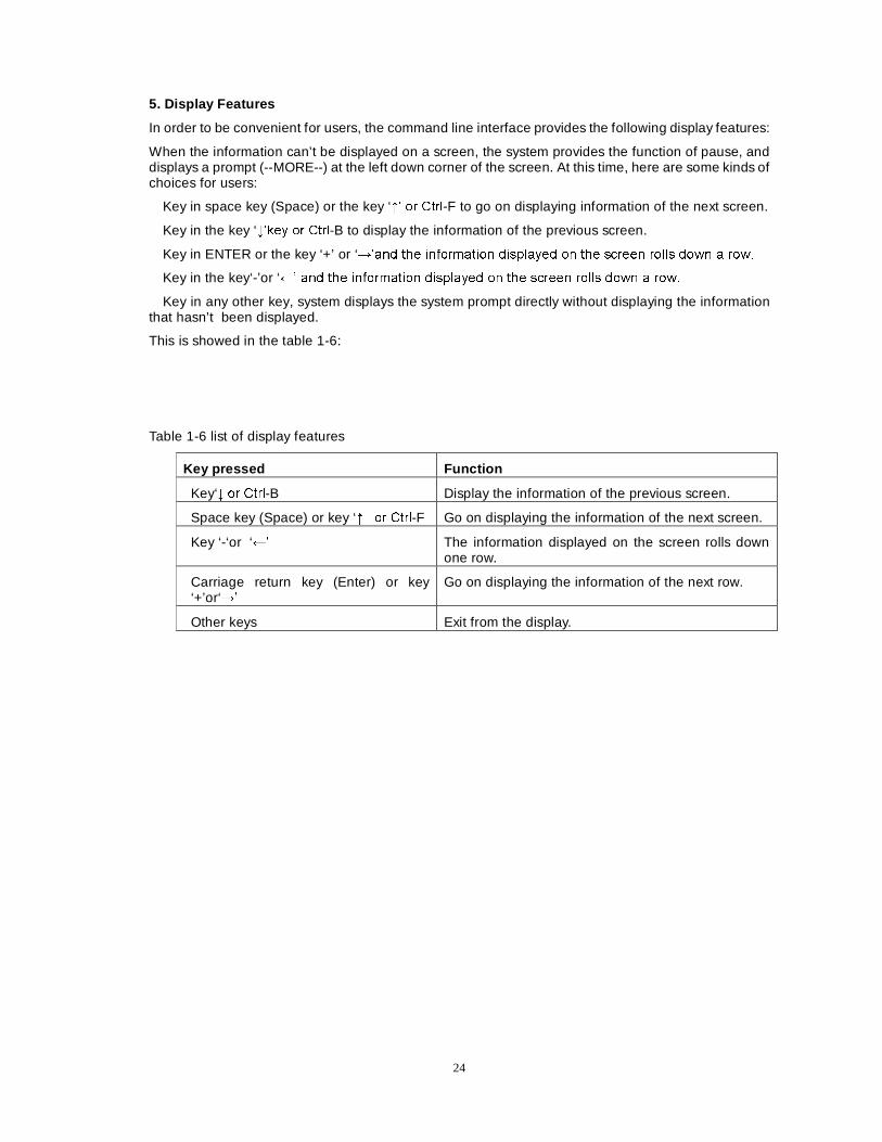
5. Display Features
In order to be convenient for users, the command line interface provides the following display features:
When the information can’t be displayed on a screen, the system provides the function of pause, and displays a prompt (--MORE--) at the left down corner of the screen. At this time, here are some kinds of choices for users:
Key in space key (Space) or the key ‘9¶ RU &WUO-F to go on displaying information of the next screen.
Key in the key ‘;¶NH\ RU &WUO-B to display the information of the previous screen.
Key in ENTER or the key ‘+’ or ‘:¶DQG WKH LQIRUPDWLRQ GLVSOD\HG RQ WKH VFUHHQ UROOV GRZQ D URZ�
Key in the key‘-’or ‘8¶ DQG WKH LQIRUPDWLRQ GLVSOD\HG RQ WKH VFUHHQ UROOV GRZQ D URZ�
Key in any other key, system displays the system prompt directly without displaying the information that hasn’t been displayed.
This is showed in the table 1-6:
Table 1-6 list of display features
Key pressed Function
Key‘;¶RU &WUO-B Display the information of the previous screen.
Space key (Space) or key ‘9¶ RU &WUO-F Go on displaying the information of the next screen.
Key ‘-‘or ‘8¶ The information displayed on the screen rolls down one row.
Carriage return key (Enter) or key ‘+’or‘:
Go on displaying the information of the next row.
Other keys Exit from the display.
25
Chapter 2 System Configuration and Management
This chapter mainly describes the basic configuration and management of Dax-Maipu, including system configuring commands, user and password management, configuration of environment parameters, file management and examination of system information etc.
The main contents of this chapter are as follow:
System configuration
System management
System tools Section 1 System Configuration
In the Dax-Maipu, the main tasks of system configuration are as follows:
�&RQILJXULQJ V\VWHP QDPH
�&RQILJXULQJ V\VWHP FORFN� ZKLFK LQFOXGHV�
Configuring the calendar system of the router: year (1970-9999), month, date, hour, minute, and second
�&RQILJXULQJ V\VWHP XVHUV
�&RQILJXULQJ WKH ERRW SDUDPHWHUV RI V\VWHP
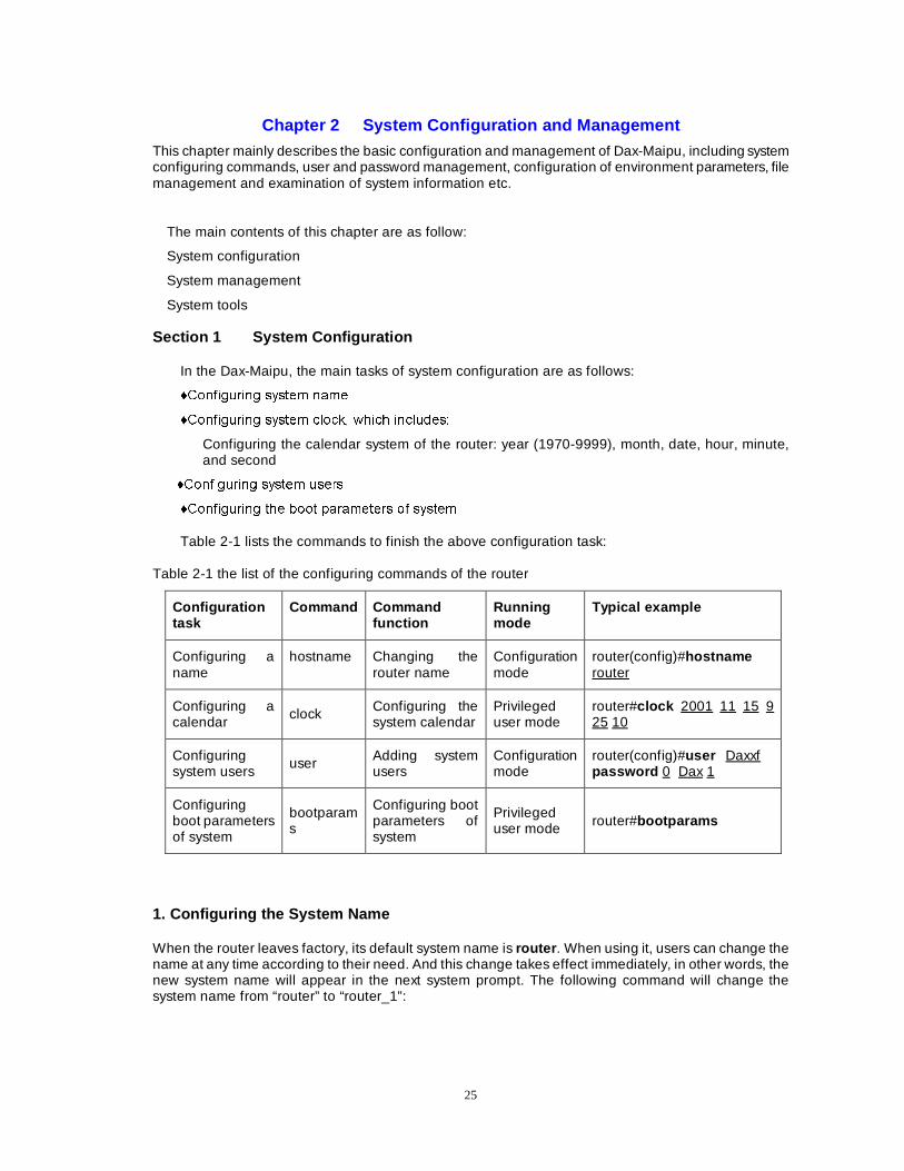
Table 2-1 lists the commands to finish the above configuration task:
Table 2-1 the list of the configuring commands of the router
Configuration task
Command Command function
Running mode
Typical example
Configuring a name
hostname Changing the router name
Configuration mode
router(config)#hostname router
Configuring a calendar
clock Configuring the system calendar
Privileged user mode
router#clock 2001 11 15 9 25 10
Configuring system users
user Adding system users
Configuration mode
router(config)#user Daxxf password 0 Dax 1
Configuring boot parameters of system
bootparams
Configuring boot parameters of system
Privileged user mode router#bootparams
1. Configuring the System Name
When the router leaves factory, its default system name is router . When using it, users can change the name at any time according to their need. And this change takes effect immediately, in other words, the new system name will appear in the next system prompt. The following command will change the system name from “router” to “router_1”:
26
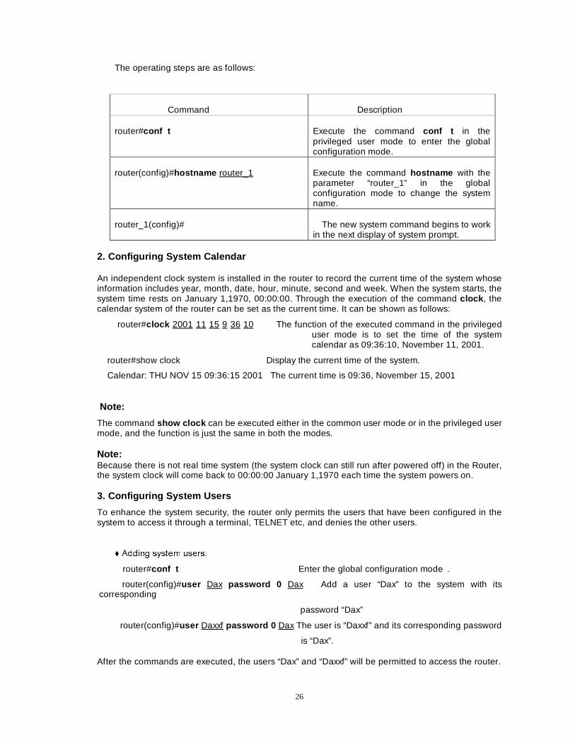
The operating steps are as follows:
Command Description
router#conf t Execute the command conf t in the privileged user mode to enter the global configuration mode.
router(config)#hostname router_1 Execute the command hostname with the parameter “router_1” in the global configuration mode to change the system name.
router_1(config)# The new system command begins to work in the next display of system prompt.
2. Configuring System Calendar
An independent clock system is installed in the router to record the current time of the system whose information includes year, month, date, hour, minute, second and week. When the system starts, the system time rests on January 1,1970, 00:00:00. Through the execution of the command clock , the calendar system of the router can be set as the current time. It can be shown as follows:
router#clock 2001 11 15 9 36 10 The function of the executed command in the privileged user mode is to set the time of the system calendar as 09:36:10, November 11, 2001.
router#show clock Display the current time of the system.
Calendar: THU NOV 15 09:36:15 2001 The current time is 09:36, November 15, 2001
Note:
The command show clock can be executed either in the common user mode or in the privileged user mode, and the function is just the same in both the modes.
Note: Because there is not real time system (the system clock can still run after powered off) in the Router, the system clock will come back to 00:00:00 January 1,1970 each time the system powers on.
3. Configuring System Users
To enhance the system security, the router only permits the users that have been configured in the system to access it through a terminal, TELNET etc, and denies the other users.
� $GGLQJ V\VWHP XVHUV�
router#conf t Enter the global configuration mode .
router(config)#user Dax password 0 Dax Add a user “Dax” to the system with its corresponding
password “Dax”
router(config)#user Daxxf password 0 Dax The user is “Daxxf” and its corresponding password
is “Dax”.
After the commands are executed, the users “Dax” and “Daxxf” will be permitted to access the router.
27
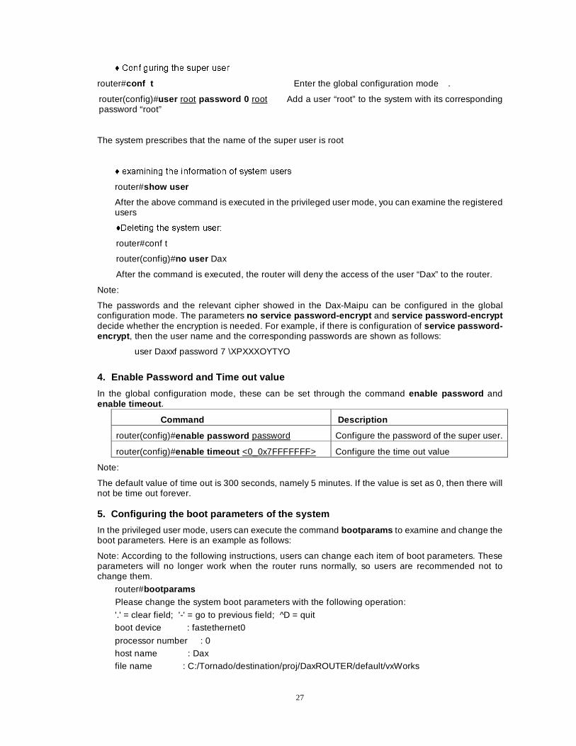
� &RQILJXULQJ WKH VXSHU XVHU
router#conf t Enter the global configuration mode .
router(config)#user root password 0 root Add a user “root” to the system with its corresponding password “root”
The system prescribes that the name of the super user is root
� H[DPLQLQJ WKH LQIRUPDWLRQ RI V\VWHP XVHUV
router#show user
After the above command is executed in the privileged user mode, you can examine the registered users
�'HOHWLQJ WKH V\VWHP XVHU�
router#conf t
router(config)#no user Dax
After the command is executed, the router will deny the access of the user “Dax” to the router.
Note:
The passwords and the relevant cipher showed in the Dax-Maipu can be configured in the global configuration mode. The parameters no service password-encrypt and service password-encrypt decide whether the encryption is needed. For example, if there is configuration of service password-encrypt , then the user name and the corresponding passwords are shown as follows:
user Daxxf password 7 \XPXXXOYTYO
4. Enable Password and Time out value
In the global configuration mode, these can be set through the command enable password and enable timeout .
Command Description
router(config)#enable password password Configure the password of the super user.
router(config)#enable timeout <0_0x7FFFFFFF> Configure the time out value
Note:
The default value of time out is 300 seconds, namely 5 minutes. If the value is set as 0, then there will not be time out forever. 5. Configuring the boot parameters of the system
In the privileged user mode, users can execute the command bootparams to examine and change the boot parameters. Here is an example as follows:
Note: According to the following instructions, users can change each item of boot parameters. These parameters will no longer work when the router runs normally, so users are recommended not to change them.
router#bootparams
Please change the system boot parameters with the following operation:
'.' = clear field; '-' = go to previous field; ^D = quit boot device : fastethernet0
processor number : 0 host name : Dax file name : C:/Tornado/destination/proj/DaxROUTER/default/vxWorks
28
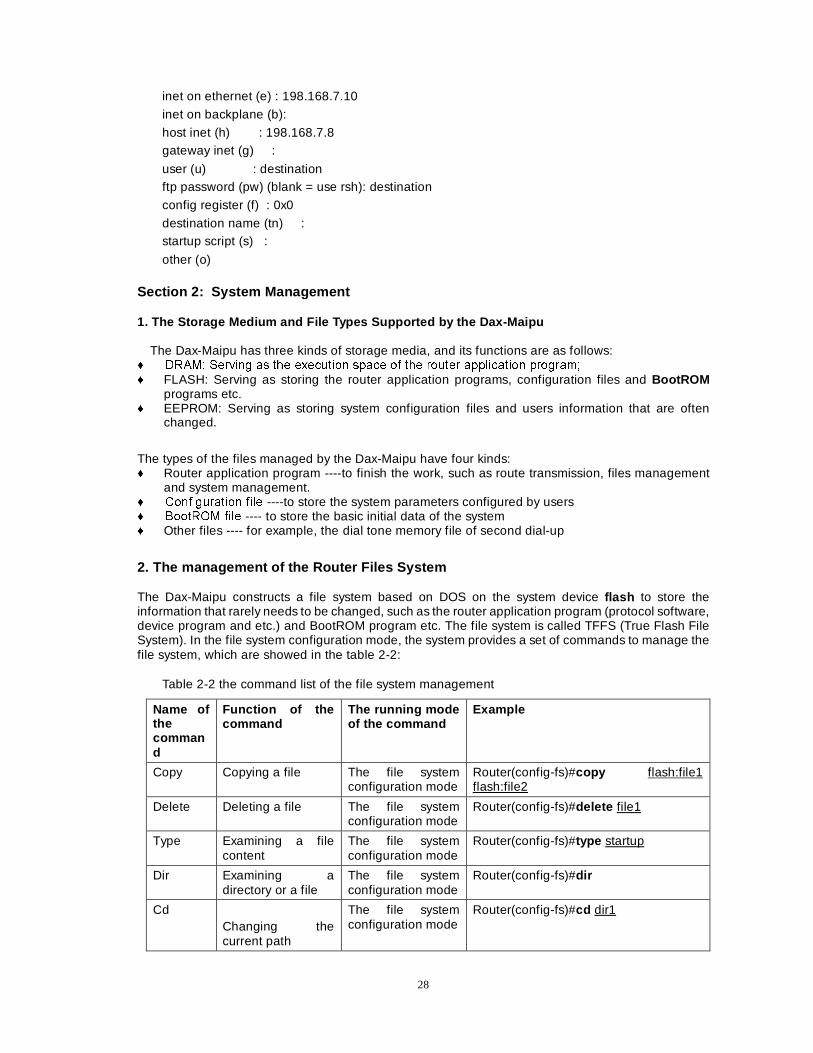
inet on ethernet (e) : 198.168.7.10
inet on backplane (b):
host inet (h) : 198.168.7.8 gateway inet (g) :
user (u) : destination ftp password (pw) (blank = use rsh): destination
config register (f) : 0x0
destination name (tn) : startup script (s) :
other (o)
Section 2: System Management 1. The Storage Medium and File Types Supported by the Dax-Maipu
The Dax-Maipu has three kinds of storage media, and its functions are as follows: � '5$0� 6HUYLQJ DV WKH H[HFXWLRQ VSDFH RI WKH URXWHU DSSOLFDWLRQ SURJUDP� � FLASH: Serving as storing the router application programs, configuration files and BootROM
programs etc. � EEPROM: Serving as storing system configuration files and users information that are often
changed.
The types of the files managed by the Dax-Maipu have four kinds: � Router application program ----to finish the work, such as route transmission, files management
and system management. � &RQILJXUDWLRQ ILOH ----to store the system parameters configured by users � %RRW520 ILOH ---- to store the basic initial data of the system � Other files ---- for example, the dial tone memory file of second dial-up
2. The management of the Router Files System The Dax-Maipu constructs a file system based on DOS on the system device flash to store the information that rarely needs to be changed, such as the router application program (protocol software, device program and etc.) and BootROM program etc. The file system is called TFFS (True Flash File System). In the file system configuration mode, the system provides a set of commands to manage the file system, which are showed in the table 2-2:
Table 2-2 the command list of the file system management
Name of the command
Function of the command
The running mode of the command
Example
Copy Copying a file The file system configuration mode
Router(config-fs)#copy flash:file1 flash:file2
Delete Deleting a file The file system configuration mode
Router(config-fs)#delete file1
Type Examining a file content
The file system configuration mode
Router(config-fs)#type startup
Dir Examining a directory or a file
The file system configuration mode
Router(config-fs)#dir
Cd Changing the current path
The file system configuration mode
Router(config-fs)#cd dir1
29
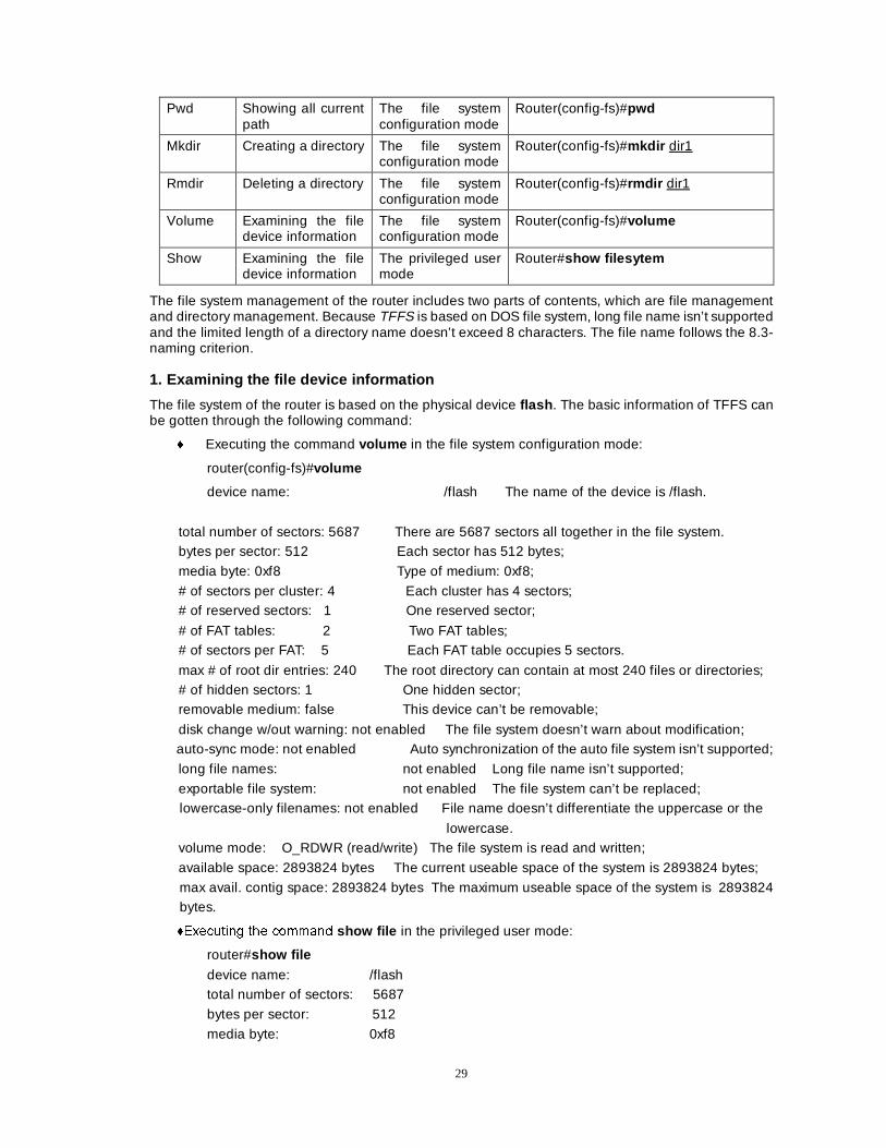
Pwd Showing all current path
The file system configuration mode
Router(config-fs)#pwd
Mkdir Creating a directory The file system configuration mode
Router(config-fs)#mkdir dir1
Rmdir Deleting a directory The file system configuration mode
Router(config-fs)#rmdir dir1
Volume Examining the file device information
The file system configuration mode
Router(config-fs)#volume
Show Examining the file device information
The privileged user mode
Router#show filesytem
The file system management of the router includes two parts of contents, which are file management and directory management. Because TFFS is based on DOS file system, long file name isn’t supported and the limited length of a directory name doesn’t exceed 8 characters. The file name follows the 8.3-naming criterion. 1. Examining the file device information
The file system of the router is based on the physical device flash . The basic information of TFFS can be gotten through the following command:
� Executing the command volume in the file system configuration mode:
router(config-fs)#volume
device name: /flash The name of the device is /flash.
total number of sectors: 5687 There are 5687 sectors all together in the file system. bytes per sector: 512 Each sector has 512 bytes;
media byte: 0xf8 Type of medium: 0xf8;
# of sectors per cluster: 4 Each cluster has 4 sectors; # of reserved sectors: 1 One reserved sector;
# of FAT tables: 2 Two FAT tables; # of sectors per FAT: 5 Each FAT table occupies 5 sectors.
max # of root dir entries: 240 The root directory can contain at most 240 files or directories; # of hidden sectors: 1 One hidden sector; removable medium: false This device can’t be removable;
disk change w/out warning: not enabled The file system doesn’t warn about modification; auto-sync mode: not enabled Auto synchronization of the auto file system isn’t supported;
long file names: not enabled Long file name isn’t supported;
exportable file system: not enabled The file system can’t be replaced; lowercase-only filenames: not enabled File name doesn’t differentiate the uppercase or the
lowercase. volume mode: O_RDWR (read/write) The file system is read and written;
available space: 2893824 bytes The current useable space of the system is 2893824 bytes;
max avail. contig space: 2893824 bytes The maximum useable space of the system is 2893824 bytes.
�([HFXWLQJ WKH FRPPDQG show file in the privileged user mode:
router#show file device name: /flash total number of sectors: 5687
bytes per sector: 512
media byte: 0xf8
30
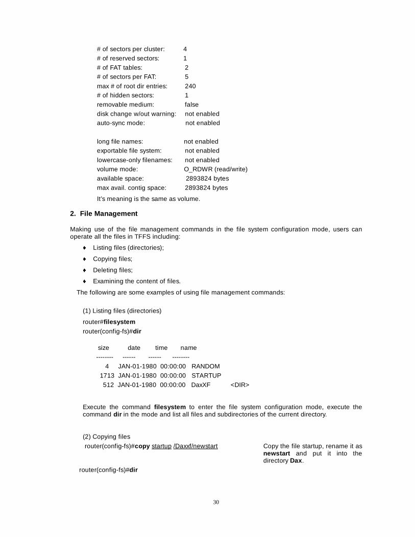
# of sectors per cluster: 4
# of reserved sectors: 1
# of FAT tables: 2 # of sectors per FAT: 5
max # of root dir entries: 240 # of hidden sectors: 1
removable medium: false
disk change w/out warning: not enabled auto-sync mode: not enabled
long file names: not enabled exportable file system: not enabled
lowercase-only filenames: not enabled volume mode: O_RDWR (read/write)
available space: 2893824 bytes
max avail. contig space: 2893824 bytes
It’s meaning is the same as volume. 2. File Management
Making use of the file management commands in the file system configuration mode, users can operate all the files in TFFS including:
� Listing files (directories);
� Copying files;
� Deleting files;
� Examining the content of files.
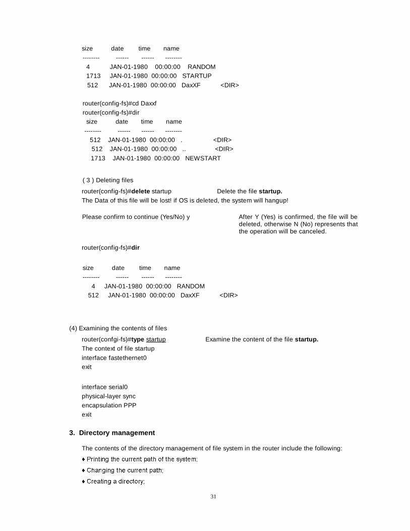
The following are some examples of using file management commands:
(1) Listing files (directories)
router#filesystem router(config-fs)#dir
size date time name
-------- ------ ------ --------
4 JAN-01-1980 00:00:00 RANDOM
1713 JAN-01-1980 00:00:00 STARTUP
512 JAN-01-1980 00:00:00 DaxXF <DIR>
Execute the command filesystem to enter the file system configuration mode, execute the command dir in the mode and list all files and subdirectories of the current directory.
(2) Copying files
router(config-fs)#copy startup /Daxxf/newstart Copy the file startup, rename it as newstart and put it into the directory Dax .
router(config-fs)#dir
31
size date time name
-------- ------ ------ --------
4 JAN-01-1980 00:00:00 RANDOM 1713 JAN-01-1980 00:00:00 STARTUP
512 JAN-01-1980 00:00:00 DaxXF <DIR>
router(config-fs)#cd Daxxf
router(config-fs)#dir size date time name
-------- ------ ------ -------- 512 JAN-01-1980 00:00:00 . <DIR> 512 JAN-01-1980 00:00:00 .. <DIR>
1713 JAN-01-1980 00:00:00 NEWSTART
( 3 ) Deleting files
router(config-fs)#delete startup Delete the file startup. The Data of this file will be lost! if OS is deleted, the system will hangup!
Please confirm to continue (Yes/No) y After Y (Yes) is confirmed, the file will be deleted, otherwise N (No) represents that the operation will be canceled.
router(config-fs)#dir
size date time name
-------- ------ ------ --------
4 JAN-01-1980 00:00:00 RANDOM 512 JAN-01-1980 00:00:00 DaxXF <DIR>
(4) Examining the contents of files
router(confgi-fs)#type startup Examine the content of the file startup. The context of file startup
interface fastethernet0 exit
interface serial0
physical-layer sync
encapsulation PPP
exit
3. Directory management
The contents of the directory management of file system in the router include the following:
� 3ULQWLQJ WKH FXUUHQW SDWK RI WKH V\VWHP�
� &KDQJLQJ WKH FXUUHQW SDWK�
� &UHDWLQJ D GLUHFWRU\�
32
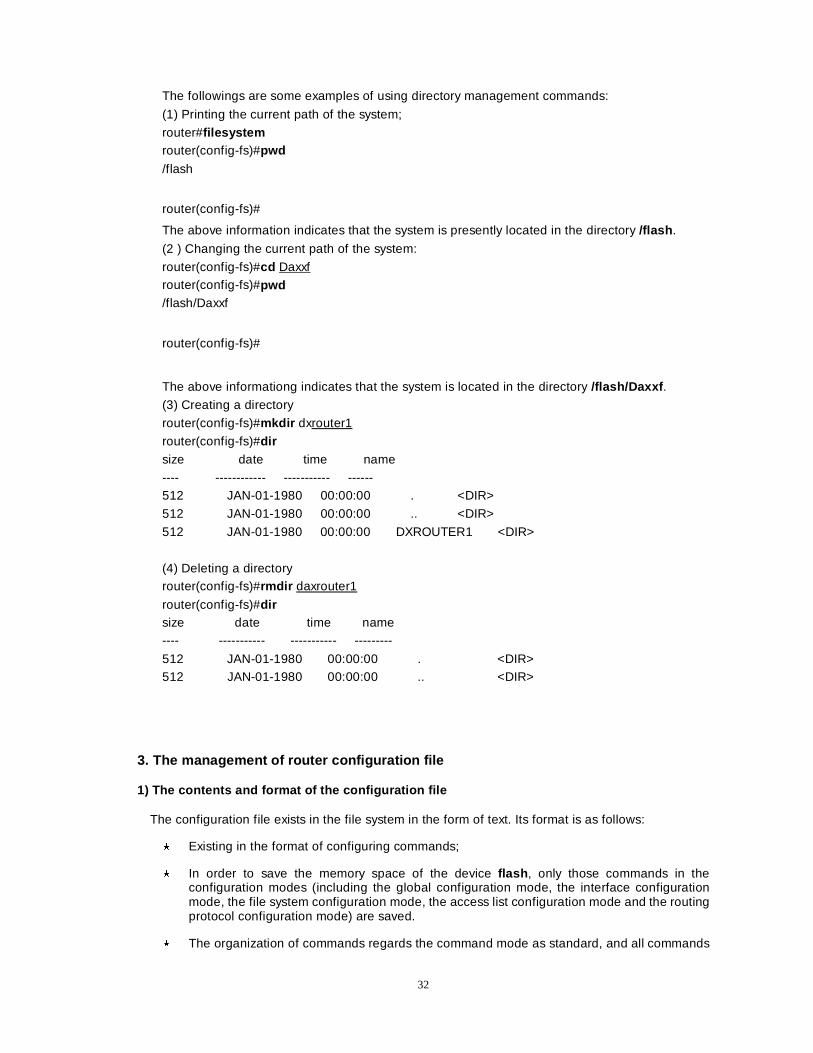
The followings are some examples of using directory management commands:
(1) Printing the current path of the system;
router#filesystem router(config-fs)#pwd /flash
router(config-fs)#
The above information indicates that the system is presently located in the directory /flash .
(2 ) Changing the current path of the system:
router(config-fs)#cd Daxxf router(config-fs)#pwd /flash/Daxxf
router(config-fs)#
The above informationg indicates that the system is located in the directory /flash/Daxxf .
(3) Creating a directory
router(config-fs)#mkdir dxrouter1
router(config-fs)#dir size date time name
---- ------------ ----------- ------ 512 JAN-01-1980 00:00:00 . <DIR>
512 JAN-01-1980 00:00:00 .. <DIR>
512 JAN-01-1980 00:00:00 DXROUTER1 <DIR>
(4) Deleting a directory router(config-fs)#rmdir daxrouter1
router(config-fs)#dir size date time name ---- ----------- ----------- ---------
512 JAN-01-1980 00:00:00 . <DIR> 512 JAN-01-1980 00:00:00 .. <DIR>
3. The management of router configuration file 1) The contents and format of the configuration file
The configuration file exists in the file system in the form of text. Its format is as follows:
� Existing in the format of configuring commands;
� In order to save the memory space of the device flash , only those commands in the configuration modes (including the global configuration mode, the interface configuration mode, the file system configuration mode, the access list configuration mode and the routing protocol configuration mode) are saved.
� The organization of commands regards the command mode as standard, and all commands
33
in the same mode are organized together to form a paragraph.
� Paragraphs are arranged in terms of specified rules: the global configuration mode, the interface configuration mode and the routing configuration mode.
� Sort the commands according to the relation among them, the relevant commands are grouped together and a blank line is used to separate groups.
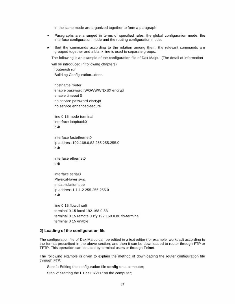
The following is an example of the configuration file of Dax-Maipu: (The detail of information
will be introduced in following chapters)
router#sh run
Building Configuration...done
hostname router
enable password [WOWWWNXSX encrypt enable timeout 0
no service password-encrypt no service enhanced-secure
line 0 15 mode terminal interface loopback0
exit
interface fastethernet0
ip address 192.168.0.83 255.255.255.0 exit
interface ethernet0
exit
interface serial3
Physical-layer sync
encapsulation ppp
ip address 1.1.1.2 255.255.255.0 exit
line 0 15 flowctl soft
terminal 0 15 local 192.168.0.83
terminal 0 15 remote 0 zfy 192.168.0.80 fix-terminal terminal 0 15 enable
2) Loading of the configuration file
The configuration file of Dax-Maipu can be edited in a text editor (for example, workpad) according to the format prescribed in the above section, and then it can be downloaded to router through FTP or TFTP. This operation can be used by terminal users or through Telnet .
The following example is given to explain the method of downloading the router configuration file through FTP:
Step 1: Editing the configuration file config on a computer;
Step 2: Starting the FTP SERVER on the computer;
34
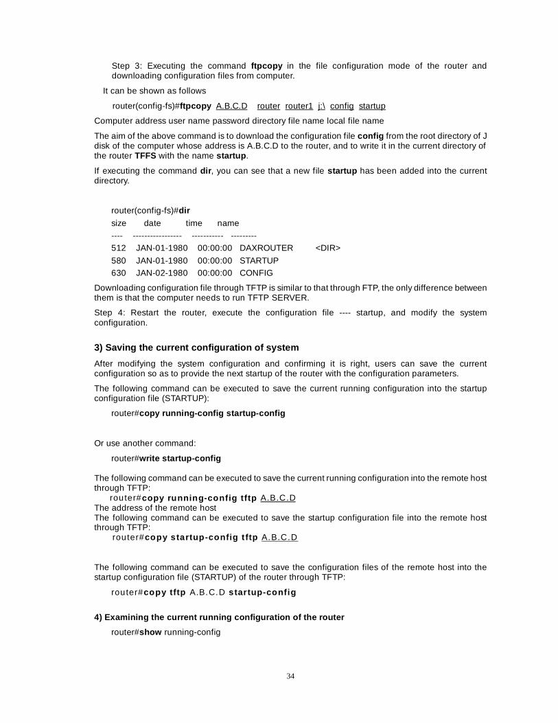
Step 3: Executing the command ftpcopy in the file configuration mode of the router and downloading configuration files from computer.
It can be shown as follows
router(config-fs)#ftpcopy A.B.C.D router router1 j:\ config startup
Computer address user name password directory file name local file name
The aim of the above command is to download the configuration file config from the root directory of J disk of the computer whose address is A.B.C.D to the router, and to write it in the current directory of the router TFFS with the name startup .
If executing the command dir , you can see that a new file startup has been added into the current directory.
router(config-fs)#dir
size date time name
---- ----------------- ----------- --------- 512 JAN-01-1980 00:00:00 DAXROUTER <DIR>
580 JAN-01-1980 00:00:00 STARTUP 630 JAN-02-1980 00:00:00 CONFIG
Downloading configuration file through TFTP is similar to that through FTP, the only difference between them is that the computer needs to run TFTP SERVER.
Step 4: Restart the router, execute the configuration file ---- startup, and modify the system configuration.
3) Saving the current configuration of system
After modifying the system configuration and confirming it is right, users can save the current configuration so as to provide the next startup of the router with the configuration parameters.
The following command can be executed to save the current running configuration into the startup configuration file (STARTUP):
router#copy running-config startup-config
Or use another command:
router#write startup-config
The following command can be executed to save the current running configuration into the remote host through TFTP:
router#copy running-config tftp A.B.C.D The address of the remote host The following command can be executed to save the startup configuration file into the remote host through TFTP:
router#copy startup-config t ftp A.B.C.D
The following command can be executed to save the configuration files of the remote host into the startup configuration file (STARTUP) of the router through TFTP:
router#copy tftp A.B.C.D s tartup-config
4) Examining the current running configuration of the router
router#show running-config
35
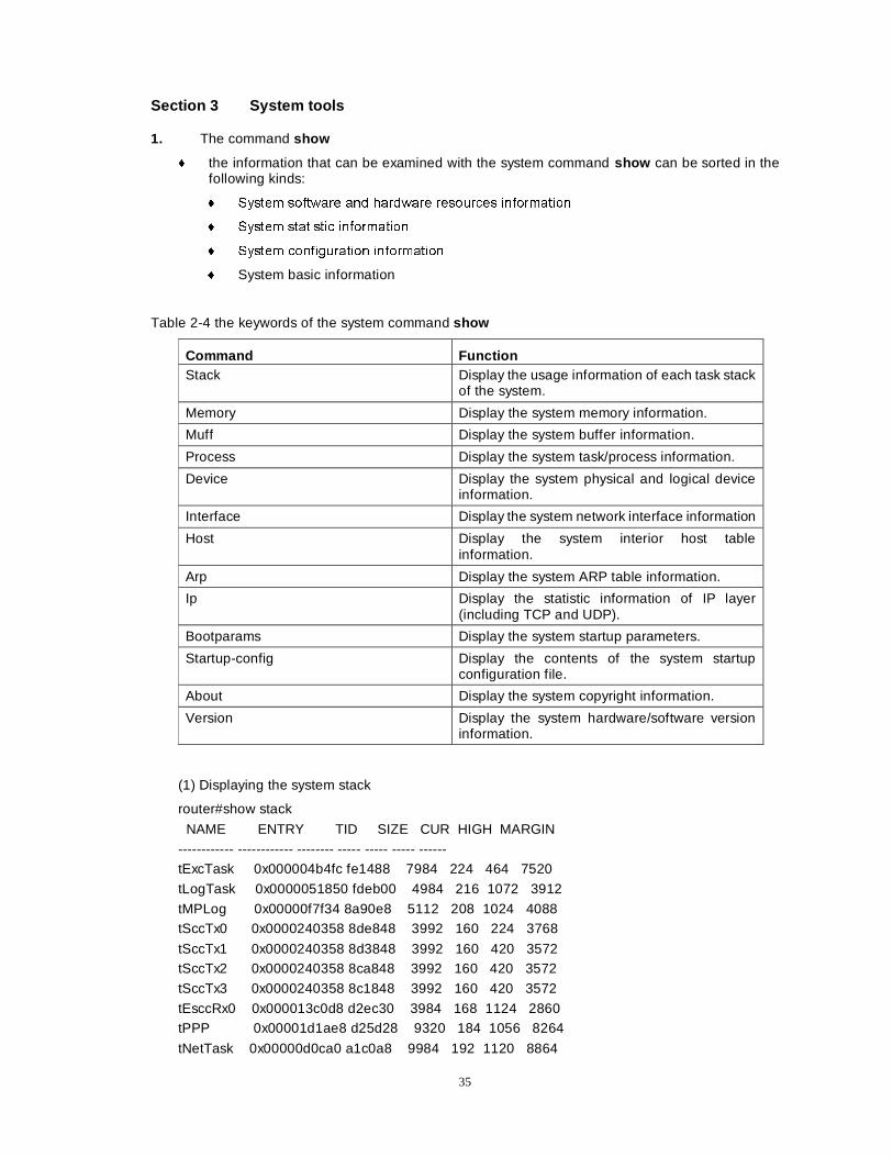
Section 3 System tools 1. The command show
� the information that can be examined with the system command show can be sorted in the following kinds:
� 6\VWHP VRIWZDUH DQG KDUGZDUH UHVRXUFHV LQIRUPDWLRQ
� 6\VWHP VWDWLVWLF LQIRUPDWLRQ
� 6\VWHP FRQILJXUDWLRQ LQIRUPDWLRQ
� System basic information
Table 2-4 the keywords of the system command show
Command Function Stack Display the usage information of each task stack
of the system.
Memory Display the system memory information.
Muff Display the system buffer information.
Process Display the system task/process information.
Device Display the system physical and logical device information.
Interface Display the system network interface information
Host Display the system interior host table information.
Arp Display the system ARP table information.
Ip Display the statistic information of IP layer (including TCP and UDP).
Bootparams Display the system startup parameters.
Startup-config Display the contents of the system startup configuration file.
About Display the system copyright information.
Version Display the system hardware/software version information.
(1) Displaying the system stack
router#show stack NAME ENTRY TID SIZE CUR HIGH MARGIN
------------ ------------ -------- ----- ----- ----- ------ tExcTask 0x000004b4fc fe1488 7984 224 464 7520
tLogTask 0x0000051850 fdeb00 4984 216 1072 3912
tMPLog 0x00000f7f34 8a90e8 5112 208 1024 4088 tSccTx0 0x0000240358 8de848 3992 160 224 3768
tSccTx1 0x0000240358 8d3848 3992 160 420 3572 tSccTx2 0x0000240358 8ca848 3992 160 420 3572
tSccTx3 0x0000240358 8c1848 3992 160 420 3572
tEsccRx0 0x000013c0d8 d2ec30 3984 168 1124 2860 tPPP 0x00001d1ae8 d25d28 9320 184 1056 8264
tNetTask 0x00000d0ca0 a1c0a8 9984 192 1120 8864
36
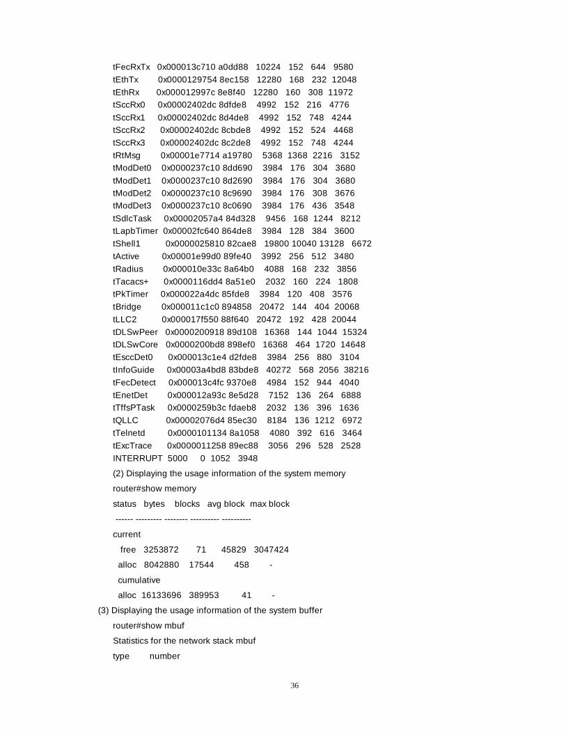
tFecRxTx 0x000013c710 a0dd88 10224 152 644 9580
tEthTx 0x0000129754 8ec158 12280 168 232 12048
tEthRx 0x000012997c 8e8f40 12280 160 308 11972 tSccRx0 0x00002402dc 8dfde8 4992 152 216 4776
tSccRx1 0x00002402dc 8d4de8 4992 152 748 4244 tSccRx2 0x00002402dc 8cbde8 4992 152 524 4468
tSccRx3 0x00002402dc 8c2de8 4992 152 748 4244
tRtMsg 0x00001e7714 a19780 5368 1368 2216 3152 tModDet0 0x0000237c10 8dd690 3984 176 304 3680
tModDet1 0x0000237c10 8d2690 3984 176 304 3680 tModDet2 0x0000237c10 8c9690 3984 176 308 3676 tModDet3 0x0000237c10 8c0690 3984 176 436 3548
tSdlcTask 0x00002057a4 84d328 9456 168 1244 8212 tLapbTimer 0x00002fc640 864de8 3984 128 384 3600
tShell1 0x0000025810 82cae8 19800 10040 13128 6672
tActive 0x00001e99d0 89fe40 3992 256 512 3480
tRadius 0x000010e33c 8a64b0 4088 168 232 3856
tTacacs+ 0x0000116dd4 8a51e0 2032 160 224 1808 tPkTimer 0x000022a4dc 85fde8 3984 120 408 3576
tBridge 0x000011c1c0 894858 20472 144 404 20068
tLLC2 0x000017f550 88f640 20472 192 428 20044
tDLSwPeer 0x0000200918 89d108 16368 144 1044 15324 tDLSwCore 0x0000200bd8 898ef0 16368 464 1720 14648
tEsccDet0 0x000013c1e4 d2fde8 3984 256 880 3104
tInfoGuide 0x00003a4bd8 83bde8 40272 568 2056 38216
tFecDetect 0x000013c4fc 9370e8 4984 152 944 4040
tEnetDet 0x000012a93c 8e5d28 7152 136 264 6888 tTffsPTask 0x0000259b3c fdaeb8 2032 136 396 1636
tQLLC 0x00002076d4 85ec30 8184 136 1212 6972
tTelnetd 0x0000101134 8a1058 4080 392 616 3464
tExcTrace 0x0000011258 89ec88 3056 296 528 2528
INTERRUPT 5000 0 1052 3948
(2) Displaying the usage information of the system memory
router#show memory
status bytes blocks avg block max block
------ --------- -------- ---------- ----------
current
free 3253872 71 45829 3047424
alloc 8042880 17544 458 -
cumulative
alloc 16133696 389953 41 -
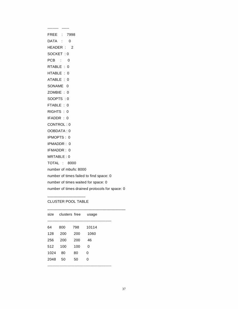
(3) Displaying the usage information of the system buffer
router#show mbuf
Statistics for the network stack mbuf
type number
37
--------- ------
FREE : 7998
DATA : 0
HEADER : 2
SOCKET : 0
PCB : 0
RTABLE : 0
HTABLE : 0
ATABLE : 0
SONAME 0
ZOMBIE : 0
SOOPTS : 0
FTABLE : 0
RIGHTS : 0
IFADDR : 0
CONTROL : 0
OOBDATA : 0
IPMOPTS : 0
IPMADDR : 0
IFMADDR : 0
MRTABLE : 0
TOTAL : 8000
number of mbufs: 8000
number of times failed to find space: 0
number of times waited for space: 0
number of times drained protocols for space: 0
__________________
CLUSTER POOL TABLE
_____________________________________
size clusters free usage
----------------------------------------------------
64 800 798 10114
128 200 200 1060
256 200 200 46
512 100 100 0
1024 80 80 0
2048 50 50 0
----------------------------------------------------
38
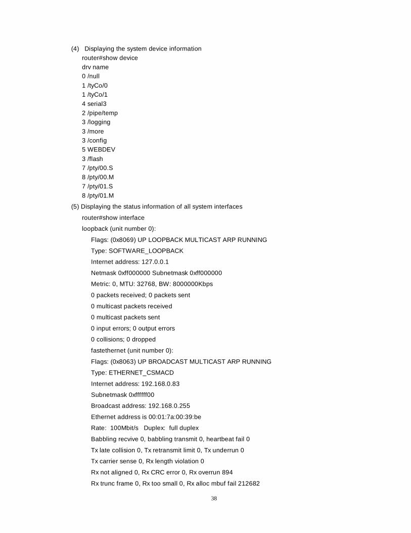
(4) Displaying the system device information
router#show device
drv name 0 /null
1 /tyCo/0 1 /tyCo/1
4 serial3
2 /pipe/temp 3 /logging
3 /more 3 /config 5 WEBDEV
3 /flash 7 /pty/00.S
8 /pty/00.M
7 /pty/01.S
8 /pty/01.M
(5) Displaying the status information of all system interfaces
router#show interface
loopback (unit number 0):
Flags: (0x8069) UP LOOPBACK MULTICAST ARP RUNNING
Type: SOFTWARE_LOOPBACK
Internet address: 127.0.0.1
Netmask 0xff000000 Subnetmask 0xff000000
Metric: 0, MTU: 32768, BW: 8000000Kbps
0 packets received; 0 packets sent
0 multicast packets received
0 multicast packets sent
0 input errors; 0 output errors
0 collisions; 0 dropped
fastethernet (unit number 0):
Flags: (0x8063) UP BROADCAST MULTICAST ARP RUNNING
Type: ETHERNET_CSMACD
Internet address: 192.168.0.83
Subnetmask 0xffffff00
Broadcast address: 192.168.0.255
Ethernet address is 00:01:7a:00:39:be
Rate: 100Mbit/s Duplex: full duplex
Babbling recvive 0, babbling transmit 0, heartbeat fail 0
Tx late collision 0, Tx retransmit limit 0, Tx underrun 0
Tx carrier sense 0, Rx length violation 0
Rx not aligned 0, Rx CRC error 0, Rx overrun 894
Rx trunc frame 0, Rx too small 0, Rx alloc mbuf fail 212682
39
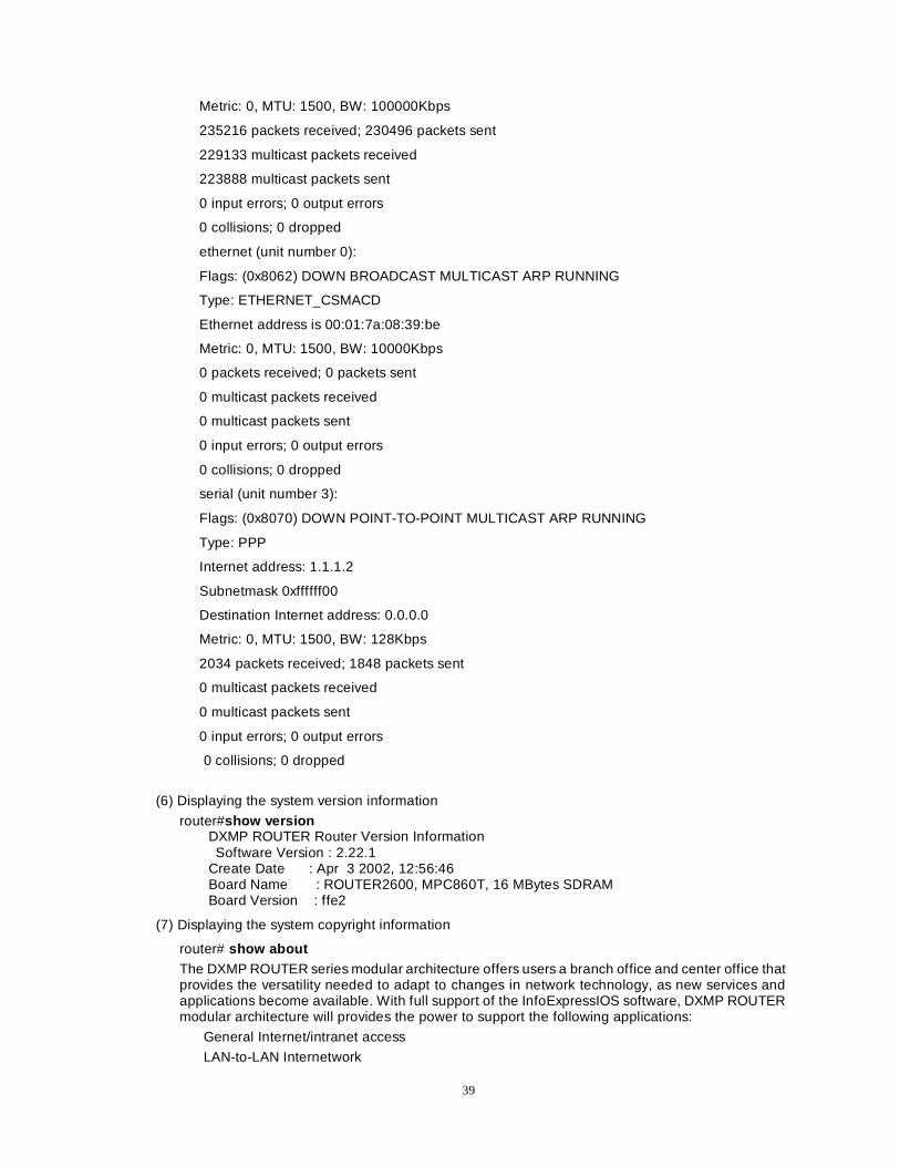
Metric: 0, MTU: 1500, BW: 100000Kbps
235216 packets received; 230496 packets sent
229133 multicast packets received
223888 multicast packets sent
0 input errors; 0 output errors
0 collisions; 0 dropped
ethernet (unit number 0):
Flags: (0x8062) DOWN BROADCAST MULTICAST ARP RUNNING
Type: ETHERNET_CSMACD
Ethernet address is 00:01:7a:08:39:be
Metric: 0, MTU: 1500, BW: 10000Kbps
0 packets received; 0 packets sent
0 multicast packets received
0 multicast packets sent
0 input errors; 0 output errors
0 collisions; 0 dropped
serial (unit number 3):
Flags: (0x8070) DOWN POINT-TO-POINT MULTICAST ARP RUNNING
Type: PPP
Internet address: 1.1.1.2
Subnetmask 0xffffff00
Destination Internet address: 0.0.0.0
Metric: 0, MTU: 1500, BW: 128Kbps
2034 packets received; 1848 packets sent
0 multicast packets received
0 multicast packets sent
0 input errors; 0 output errors
0 collisions; 0 dropped
(6) Displaying the system version information
router#show version DXMP ROUTER Router Version Information
Software Version : 2.22.1 Create Date : Apr 3 2002, 12:56:46 Board Name : ROUTER2600, MPC860T, 16 MBytes SDRAM Board Version : ffe2
(7) Displaying the system copyright information
router# show about
The DXMP ROUTER series modular architecture offers users a branch office and center office that provides the versatility needed to adapt to changes in network technology, as new services and applications become available. With full support of the InfoExpressIOS software, DXMP ROUTER modular architecture will provides the power to support the following applications:
General Internet/intranet access
LAN-to-LAN Internetwork
40
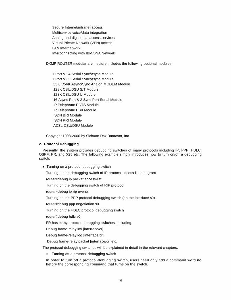
Secure Internet/intranet access
Multiservice voice/data integration
Analog and digital dial access services Virtual Private Network (VPN) access
LAN Internetwork Interconnecting with IBM SNA Network
DXMP ROUTER modular architecture includes the following optional modules:
1 Port V.24 Serial Sync/Async Module 1 Port V.35 Serial Sync/Async Module
33.6K/56K Async/Sync Analog MODEM Module
128K CSU/DSU S/T Module 128K CSU/DSU U Module
16 Async Port & 2 Sync Port Serial Module
IP Telephone POTS Module
IP Telephone PBX Module
ISDN BRI Module ISDN PRI Module
ADSL CSU/DSU Module
Copyright 1998-2000 by Sichuan Dax Datacom, Inc 2. Protocol Debugging
Presently, the system provides debugging switches of many protocols including IP, PPP, HDLC, OSPF, FR, and X25 etc. The following example simply introduces how to turn on/off a debugging switch:
� 7XUQLQJ RQ D SURWRFRO-debugging switch
Turning on the debugging switch of IP protocol access-list datagram
router#debug ip packet access-list
Turning on the debugging switch of RIP protocol
router#debug ip rip events
Turning on the PPP protocol debugging switch (on the interface s0)
router#debug ppp negotiation s0
Turning on the HDLC protocol debugging switch
router#debug hdlc s0
FR has many protocol debugging switches, including
Debug frame-relay lmi [interface/cr]
Debug frame-relay log [interface/cr]
Debug frame-relay packet [interface/cr] etc.
The protocol-debugging switches will be explained in detail in the relevant chapters.
� Turning off a protocol-debugging switch
In order to turn off a protocol-debugging switch, users need only add a command word no before the corresponding command that turns on the switch.

41
3. Network Troubleshooting tools
This will be explained in detail in chapter “Network Debugging and Fault Diagnosis”.
Section 4 System software update This will be explained in detail in chapter “Software Update”.
42
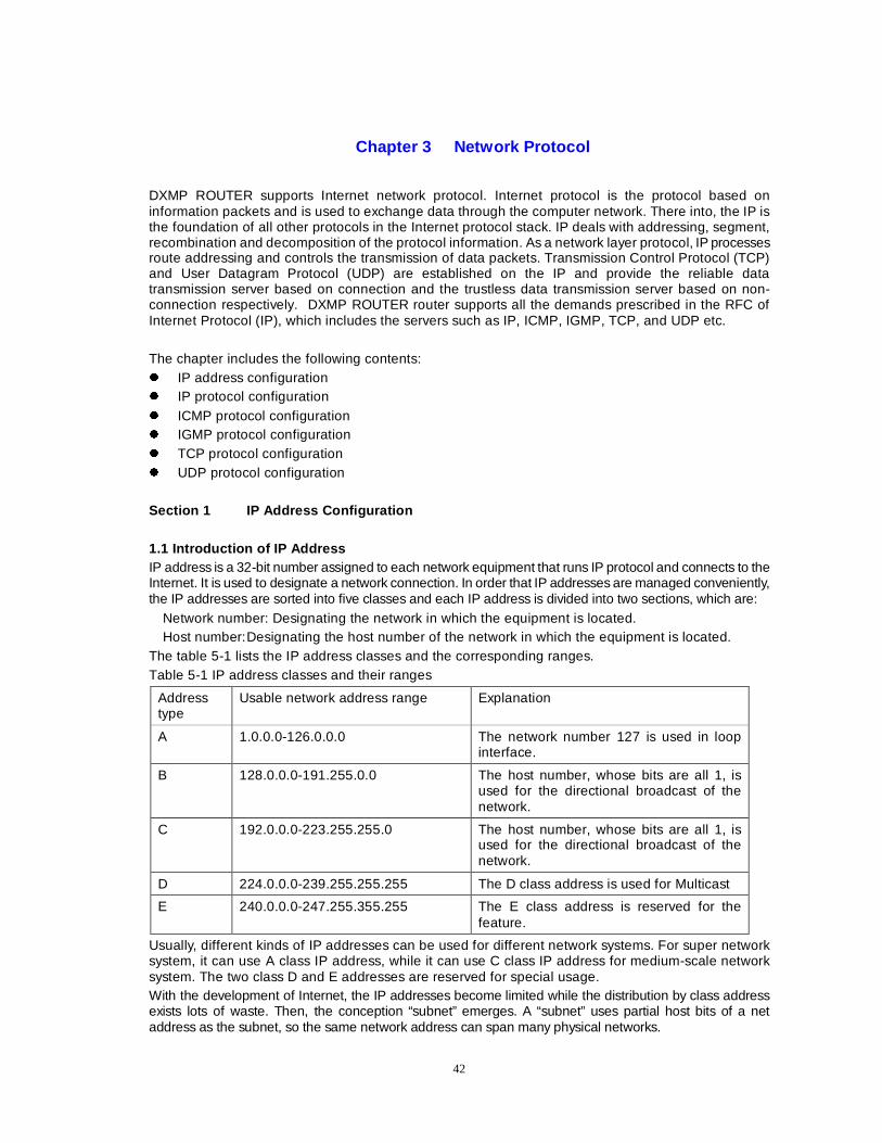
Chapter 3 Network Protocol
DXMP ROUTER supports Internet network protocol. Internet protocol is the protocol based on information packets and is used to exchange data through the computer network. There into, the IP is the foundation of all other protocols in the Internet protocol stack. IP deals with addressing, segment, recombination and decomposition of the protocol information. As a network layer protocol, IP processes route addressing and controls the transmission of data packets. Transmission Control Protocol (TCP) and User Datagram Protocol (UDP) are established on the IP and provide the reliable data transmission server based on connection and the trustless data transmission server based on non-connection respectively. DXMP ROUTER router supports all the demands prescribed in the RFC of Internet Protocol (IP), which includes the servers such as IP, ICMP, IGMP, TCP, and UDP etc. The chapter includes the following contents: z IP address configuration z IP protocol configuration z ICMP protocol configuration z IGMP protocol configuration z TCP protocol configuration z UDP protocol configuration Section 1 IP Address Configuration 1.1 Introduction of IP Address IP address is a 32-bit number assigned to each network equipment that runs IP protocol and connects to the Internet. It is used to designate a network connection. In order that IP addresses are managed conveniently, the IP addresses are sorted into five classes and each IP address is divided into two sections, which are:
Network number: Designating the network in which the equipment is located. Host number: Designating the host number of the network in which the equipment is located.
The table 5-1 lists the IP address classes and the corresponding ranges. Table 5-1 IP address classes and their ranges
Address type
Usable network address range Explanation
A 1.0.0.0-126.0.0.0 The network number 127 is used in loop interface.
B 128.0.0.0-191.255.0.0 The host number, whose bits are all 1, is used for the directional broadcast of the network.
C 192.0.0.0-223.255.255.0 The host number, whose bits are all 1, is used for the directional broadcast of the network.
D 224.0.0.0-239.255.255.255 The D class address is used for Multicast
E 240.0.0.0-247.255.355.255 The E class address is reserved for the feature.
Usually, different kinds of IP addresses can be used for different network systems. For super network system, it can use A class IP address, while it can use C class IP address for medium-scale network system. The two class D and E addresses are reserved for special usage. With the development of Internet, the IP addresses become limited while the distribution by class address exists lots of waste. Then, the conception “subnet” emerges. A “subnet” uses partial host bits of a net address as the subnet, so the same network address can span many physical networks.
43
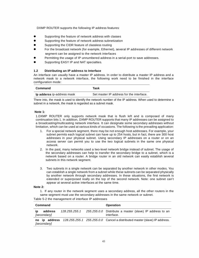
DXMP ROUTER supports the following IP address features:
z Supporting the feature of network address with classes z Supporting the feature of network address subnetization z Supporting the CIDR feature of classless routing z For the broadcast network (for example, Ethernet), several IP addresses of different network segment can be assigned to the network interfaces z Permitting the usage of IP unnumbered address in a serial-port to save addresses. z Supporting EASY IP and NAT specialties. 1.2 Distributing an IP address to Interface An interface can usually have a master IP address. In order to distribute a master IP address and a network mask to a network interface, the following work need to be finished in the interface configuration mode:
Command Task
Ip adderss ip-address mask Set master IP address for the interface.
There into, the mask is used to identify the network number of the IP address. When used to determine a subnet in a network, the mask is regarded as a subnet mask. Note 1:
1.DXMP ROUTER only supports network mask that is flush left and is composed of many continuation bits 1. In addition, DXMP ROUTER supports that many IP addresses can be assigned to a broadcasting/multicasting network interface. It can designate some secondary addresses without limitation, which can be used at various kinds of occasions. The following is the prevailing application:
1. For a special network segment, there may be not enough host addresses. For example, your subnet permits each logical subnet can have up to 254 hosts, but in fact, there are 300 host addresses in your physical subnet. Using secondary IP addresses on a router or on an access server can permit you to use the two logical subnets in the same one physical network.
2. In the past, many networks used a two-level network bridge instead of subnet. The usage of the secondary addresses can help to transfer the secondary bridge to a subnet, which is a network based on a router. A bridge router in an old network can easily establish several subnets in this network segment.
3. Two subnets in a single network can be separated by another network in other modes. You
can establish a single network from a subnet while these subnets can be separated physically by another network through secondary addresses. In these situations, the first network is extended or superposed really on the top of the second network. Note: one subnet can’t appear at several active interfaces at the same time.
Note 2: 1. If any router in the network segment uses a secondary address, all the other routers in the same segment must use the secondary addresses in the same network or subnet.
Table 5-2 the management of interface IP addresses
Command Operation
ip address 128.255.255.1 255.255.0.0 [secondary]
Distribute a master (slave) IP address to an interface.
no ip address 128.255.255.1 255.255.0.0 [secondary]
Cancel a distributed master (slave) IP address.
44
Example: The following example distributes a master IP address and two secondary IP addresses for the interface Fastethernet0(serial0):
DXMP ROUTER#conf t DXMP ROUTER(config)#interface Fastethernet0 DXMP ROUTER(config-if-fastethernet0)#ip address 128.255.255.1 255.255.0.0 DXMP ROUTER(config-if-fastethernet0)#ip address 128.254.255.1 255.255.0.0 secondary DXMP ROUTER(config-if-fastethernet0)#ip address 128.253.255.1 255.255.0.0 secondary
Noticeable points: z Several slave IP addresses configured for the same interface have a successive relation
according to the configuration time. At the same time, for the convenience of data packets routing transmission of the router, every interface IP address must be in the different network segment (AnIP address has different network parts).
1.3 Enabling the Unnumbered Process Valid on a Serial Port The IP unnumbered process is a method to save IP addresses in Internet networks. You can make IP unnumbered process effective on a serial-port, instead of distributing an obvious IP address to the interface. Whenever an unnumbered interface produces a packet (for example, updating a routing), it will use the interface address designated by you as the source address of IP packet. It also uses the designated interface address to determine which route process is sending the updated content to the unnumbered interface. There are some following limitations: · Serial-port presently supports Point-to-Point Protocol (PPP) and High-Level Data Link Control (HDLC). And it will soon provide supports to Link Access Process Balance (LAPB), Serial Line Internet Protocol (SLIP) and Tunnel interface. · The command ping EXEC cannot be used to test and connect the interface for it hasn’t IP address.
But the Simple Network Management Protocol (SNMP) can be used to remote monitor the interface status.
· Unnumbered serial interface cannot be used to perform network guiding for a mapping that can run. · IP security option cannot be supported on a unnumbered interface. This is described in the RFC 1195; IP address is not indispensable for every interface. Noticeable points:
z It should be careful when an unnumbered serial-cable is used between the different main networks. In each connection end, if some different main networks are distributed to the interface that you designate as unnumbered, any router protocol running through a serial line will be configured as one that cannot publish subnet information.
In order to enable an IP process valid on an unnumbered serial port, the following task should be finished in the interface configuration mode:
Command Task
Ip unnumbered <reference interface> Enable IP unnumbered management valid on a serial port, and don’t distribute an obvious IP address to the interface.
The interface must be a name of another interface in a router with an IP address, instead of another unnumbered interface. The designated interface must also effective. 1.4 Setting IP Address Negotiation Property of an Interface For the data link layer protocol PPP supporting the address negotiation, the negotiation property of an interface IP address can be set without configuring the interface IP address. It’s typical that the PPP protocol runs on serial circuitries to connect ISP to access Internet. The commands listed in the table 5-3 set the IP address negotiation of the local serial interface, and permit the local interface to receive the address distributed to the interface of the opposite terminal.
45
Table 5-3 setting the negotiation property of interface IP address
Command Operation
Ip address negotiated Configure the IP address negotiation of the interface.
No ip address negotiated Cancel the IP address negotiation of the interface
1.5 Examining IP Address Configuration After configuring the interface IP address, users can use the command show interface to examine the information of the IP address configured for the interface.
router79#sh int f0 fastethernet (unit number 0):
Flags: (0x8063) UP BROADCAST MULTICAST ARP RUNNING Type: ETHERNET_CSMACD Internet address: 192.168.0.79 IP address 192.168.0.79 Netmask 0xffffff00 Subnetmask 0xffffff00 24 bits network mask, 24 bits subnet mask Broadcast address: 192.168.0.255 the local network directional broadcasting address 192.168.0.255
Ethernet address is 00:01:7a:01:1c:0b Rate: 100Mbit/s Duplex: full duplex Babbling recvive 0, babbling transmit 0, heartbeat fail 0 Tx late collision 0, Tx retransmit limit 0, Tx inrun 0 Section 2 Address Resolutions
DXMP ROUTER permits you to designate IP process through address resolution and naming service.
2.1 Establishing Address Resolution (ARP) In IP, an equipment has a data link (MAC) address (exclusively identifying an interface in LAN), and it can also has a network address (identifying host number and the network in which the equipment is located). In order to communicate with equipment in the Ethernet, for example, DXMP ROUTER must decide the 48 bits MAC address firstly. The process to decide a local data link MAC address from an IP address is called address resolution. The other process to decide an IP address from a local data link MAC address is called reverse address resolution (RAR). DXMP ROUTER supports the Ethernet Address Resolution Protocol (ARP). ARP is used to associate an address with a MAC address. An IP address is seen as input, and ARP decides the relative MAC address. Once a MAC address is decided, the IP address/MAC address association is stored into the ARP cache so as to be searched high-speedily. Then, IP datagram is encapsulated in the frame of the data link layer and sent in the network.
Definition ---- static ARP cache Between the IP address and the MAC medium address, ARP provides a dynamic mapping. Because most hosts support dynamical address resolution, it needn’t, generally, to designate the option of static ARP cache. If users need to define them, they can define them globally ---- load a permanent option into the ARP cache. DXMP ROUTER software uses this option to translate the 32 bits address into 48 bits address. Execute the following commands in the global configuration mode:
Arp ip-address ethernet-address Defining a static ARP cache No arp ip-address ethernet-address Deleting a static ARP cache
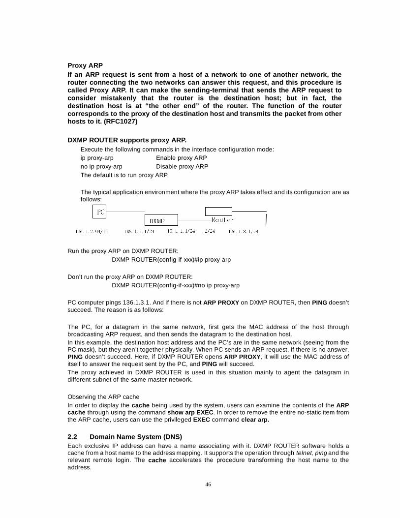
46
Proxy ARP If an ARP request is sent from a host of a network to one of another network, the router connecting the two networks can answer this request, and this procedure is called Proxy ARP. It can make the sending-terminal that sends the ARP request to consider mistakenly that the router is the destination host; but in fact, the destination host is at “the other end” of the router. The function of the router corresponds to the proxy of the destination host and transmits the packet from other hosts to it. (RFC1027) DXMP ROUTER supports proxy ARP.
Execute the following commands in the interface configuration mode: ip proxy-arp Enable proxy ARP no ip proxy-arp Disable proxy ARP The default is to run proxy ARP.
The typical application environment where the proxy ARP takes effect and its configuration are as follows:
Run the proxy ARP on DXMP ROUTER: DXMP ROUTER(config-if-xxx)#ip proxy-arp Don’t run the proxy ARP on DXMP ROUTER: DXMP ROUTER(config-if-xxx)#no ip proxy-arp PC computer pings 136.1.3.1. And if there is not ARP PROXY on DXMP ROUTER, then PING doesn’t succeed. The reason is as follows:
The PC, for a datagram in the same network, first gets the MAC address of the host through broadcasting ARP request, and then sends the datagram to the destination host. In this example, the destination host address and the PC’s are in the same network (seeing from the PC mask), but they aren’t together physically. When PC sends an ARP request, if there is no answer, PING doesn’t succeed. Here, if DXMP ROUTER opens ARP PROXY, it will use the MAC address of itself to answer the request sent by the PC, and PING will succeed. The proxy achieved in DXMP ROUTER is used in this situation mainly to agent the datagram in different subnet of the same master network. Observing the ARP cache In order to display the cache being used by the system, users can examine the contents of the ARP cache through using the command show arp EXEC . In order to remove the entire no-static item from the ARP cache, users can use the privileged EXEC command clear arp. 2.2 Domain Name System (DNS) Each exclusive IP address can have a name associating with it. DXMP ROUTER software holds a cache from a host name to the address mapping. It supports the operation through telnet, ping and the relevant remote login. The cache accelerates the procedure transforming the host name to the address.
';03 5RXWHU 3&
������������� ������������ ����������� ����� ������������
47
IP defines a naming method that permits an equipment can be identified by its location in IP. This is a method that provides hierarchical naming for domains. In order to keep on tracking the domain name, IP defines the conception of Domain Name System (DNS) whose work is to keep a buffer (or database) that maps domain names to IP addresses. In order to map domain names to IP addresses, you must identify the host name firstly, and then designate the domain name server to enable Domain Naming System to become effective. This is the global naming scheme for Internet to identify network equipment exclusively.
Mapping IP addresses to host names DXMP ROUTER holds a table that saves host names and their corresponding addresses. The table is also called the mapping table. Advanced protocols, such as the remote login, use host names to identify network equipments (hosts). Routers and other network equipments must realize the association of IP addresses with static or dynamic tools. When the dynamic mapping cannot be used, addresses can be distributed to host names manually. Distribute host names to addresses, and execute the following tasks in the global configuration mode:
host host_name Ip_Address Defining a mapping of host names and IP addresses no host host_name Ip_Address Deleting a mapping of host names and IP addresses
Designating a domain name You can designate a default domain name for a router. The domain name will be used by the system to finish the domain name request. You can designate either a single domain name or a series of domain names. It’s up to you do designate the domain before an IP host name that doesn’t include a domain name is added into the host table. In order to designate a domain name or a name, execute any task of the following in the global configuration mode:
domain-name name Define a default domain name. no domain-name name Cancel a default domain name.
Designating a domain name server One or more hosts (at most 6 hosts) can be designated as the domain name server(s) to provide DNS with name information service. Execute the following tasks in the global configuration mode:
name-server server-address Define a domain name server no name-server server-address Cancel a domain name server.
Designating the order used by domain name service When a system uses the name service to finish name resolution, firstly, it uses the default local name Cache , then, uses DNS service to finish name resolutions. But users can also designate that the system only uses DNS service to finish name resolutions (in this way, users can map an IP addresses to a host name non-manually)
Executing the following tasks in the global configuration mode: name-order {dns-first|dns-only|local-first}
48
Section 3: IP protocol
3.1 Permitting/ Prohibiting IP Routing Transmission The default setting of DXMP ROUTER router permits IP routing transmission. But in some special situations, users can prohibit the routing function, which can be finished through the following operations: In the global configuration mode, users can prohibit IP routing transmission through the command no ip routing . In the global configuration mode, users can permit IP routing transmission through the command ip routing .
3.2 Permitting/ Prohibiting IP Sending Redirection Message The default setting of DXMP ROUTER router permits the router to send IP redirection. But in some special situations, users can prohibit the function to send IP redirection, which can be finished through the following operations: Executing the following commands in the global configuration mode:
ip redirect Enable IP redirect no ip redirect Enable IP redirect
The default setting is to permit. In the global configuration mode, users can prohibit IP of all interfaces from sending IP redirection through the command no ip redirect ; In the global configuration mode, users can permit IP of all interfaces to send IP redirection through the command ip redirec t. Executing the following commands in the interface configuration mode:
ip redirects Enable sending ICMP Redirect messages no ip redirects Disable sending ICMP Redirect messages
The default setting is to permit. In the interface configuration mode, users can prohibit this interface IP from sending IP redirection through the command no ip redirect ; In the interface configuration mode, users can permit this interface IP to send IP redirection through the command ip redirect.
3.3 Permitting/Prohibiting IP Receiving Redirection Message The redirection packet icmp can result in the update of the routing table. The default setting of DXMP ROUTER is not to update route after the router receives the redirection packet icmp . But users can select the route update.
Executing the following commands in global configuration mode:
icmp redirect-route Enable to add icmp redirect route no icmp redirect-route Disable to add icmp redirect route The default setting is to prohibit the routing update.
49
3.4 IP Fast Transmission The IP fast transmission is realized through route cache mechanism. The aim of route cache is to reduce the repeated search of routing table and to accelerate the packets sending speed through using the search result, which is gotten when sending packets before, of the routing table. But in some special situation, users can choose prohibiting/permitting the following two cases to process route cache. 1) Fast transmitting route cache. Many routes can be stored in cache to transmit packets directly if
the cache conditions are met before the packets received by an interface are sent to IP layer to deal with. Executing the following commands in the interface configuration mode: ip route-cache Enable fast-switching cache for outgoing packets no ip route-cache Disable fast-switching cache for outgoing packets The default setting is to permit.
2) When there are packets sent down from the user layer, if the destination is the same each time
and the route is UP, the route in cache can be used without searching. Only one route, which is the result of recently searching the routing table, needs to be stored in cache. Executing the following commands in the global configuration mode: ip upper-cache Enable using upper route cache no ip upper-cache Disable using upper route cache The default setting is to permit.
3.5 Opening/Closing IP Source Address Examination The default setting of DXMP ROUTER router is to open the IP source address examination (RFC1812). But in some special situations, users can prohibit the function to examine source address, and this can be finished through the following operations: Executing the following commands in the global configuration mode: ip source-check Check source address if reasonable no ip source-check Not check source address if reasonable The default setting is to permit.
3.6 Configuring IP Protocol Properties DXMP ROUTER can configure the following UDP properties:
z Configuring the depth of the IP protocol input queue z Configuring the default Time-To-Live (TTL) of sending IP datagram z Configuring the default Time-To-Live (TTL) of sending the fragmented IP datagram z Configuring the examination of IP receiving datagram checksum (recv-checksum) z Configuring the generation of IP sending datagram checksum (recv-checksum)
The table 5-5 lists the commands to configure the UDP properties:
50
Table 5-5 UDP properties configuration
Command Operation
ip option default-ttl [1-255] Configure the Time-To-Live of IP.
ip option fragment-ttl [1-255] Configure the Time-To-Live of IP fragment.
ip option queue-length [300-600] Configuring the length of the IP receive-buffer.
ip option recv-checksum Configuring receiving datagram checksum (recv-checksum).
ip option send-checksum Configure sending datagram checksum (recv-checksum).
3.7 Observing IP Statistic Data
DXMP ROUTER#show ip statistics
Statistics for the IP protocol
total 1356 ---The number of the total received/sent packets
badsum 0 ---The number of the packets checked to be wrong
tooshort 0 ---The number of the packets that are too short
toosmall 0 ---The number of the packets that are too small
badhlen 0 ---The times of the errors of the head length domain
badlen 0 ---The times of the information length errors
infragments 0 ---The number of the received fragment packets
fragdropped 0 ---The number of the discarded fragment packets
fragtimeout 0 ---The number of packets that are fragmented overtime
forward 0 ---The number of the transmitted packets
cantforward 1312 ---The number of packets unable to transmit
redirectsent 0 ---The sending times of redirection
unknownprotocol 16 ---The number of packets with unknown protocols
nobuffers 0 ---The times of no buffers
reassembled 0 ---The number of datagram reassembly
outfragments 0 ---The number of the sent fragments
noroute 0 ---The times of without routing
51
Section 4 ICMP protocol In the Internet protocol stack, the Internet Control Message Protocol (ICMP) provides other protocols with services such as control, error report and network testing. DXMP ROUTER supports RFC792, RFC950 and RFC1122.
4.1 Configuring ICMP Options The default configuration of ICMP supports the option of subnet mask request and acknowledge. But users can sometimes close this option.
No Ip mask-reply Close the option of subnet request and acknowledge. Ip mask-reply Enable the option of subnet request and acknowledge.
4.2 Observing ICMP Statistic Information
router#sh ip icmp
Statistics for ICMP protocol
16 calls to icmp error ---The times for system to call ICMP to send error messages
0 error not generated because old message was icmp
---The times of errors caused by the overtime ICMP packets
Output histogram: ---The sending situation
Destination unreachable: 16 ---The times of the unreachable destination
0 message with bad code fields ---The number of packets with wrong code domain
0 message < minimum length>
0 bad checksum ---The times of the received check errors
0 message with bad length ---The times of the received packet length errors
Input histogram: ---The receiving situation
Destination unreachable: 16 ---The times of unreachable destination
0 message response generated ---The number of the generated messages response
Section 5 IGMP protocol In the Internet protocol stack, the Internet Group Management Protocol (IGMP) assists IP to provide other application programs with multicast service. DXMP ROUTER supports RFC1122. The command Show ip igmp can be executed to observe the working situation of the IGMP protocol.
DXMP ROUTER#show ip igmp
Statistics for the IGMP protocol
0 invalid queries received ----The query times of the invalid group members
0 invalid reports received ---- The report times of the invalid group members
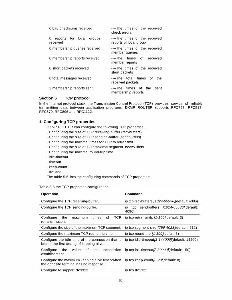
52
0 bad checksums received ----The times of the received check errors.
0 reports for local groups received
----The times of the received reports of local group
0 membership queries received ----The times of the received member queries
0 membership reports received ----The times of received member reports
0 short packets received ----The times of the received short packets
0 total messages received ----The total times of the received packets
2 membership reports sent ----The times of the sent membership reports
Section 6 TCP protocol In the Internet protocol stack, the Transmission Control Protocol (TCP) provides service of reliably transmitting data between application programs. DXMP ROUTER supports RFC793, RFC813, RFC879, RFC896 and RFC1122.
1. Configuring TCP properties
DXMP ROUTER can configure the following TCP properties: · Configuring the size of TCP receiving-buffer (recvbuffers) · Configuring the size of TCP sending-buffer (sendbuffers) · Configuring the maximal times for TCP to retransmit · Configuring the size of TCP maximal segment�UHFYEXIIHUV� · Configuring the maximal round-trip time · idle-timeout · timeout · keep-count · rfc1323 The table 5-6 lists the configuring commands of TCP properties:
Table 5-6 the TCP properties configuration
Operation Command
Configure the TCP receiving-buffer. ip tcp recvbuffers [1024-65536](default: 4096)
Configure the TCP sending-buffer. ip tcp sendbuffers [1024-65536](default: 4096)
Configure the maximum times of TCP retransmission.
ip tcp retransmits [1-100](default: 3)
Configure the size of the maximum TCP segment. ip tcp segment-size [256-4028](default: 512)
Configure the maximum TCP round trip time. ip tcp round-trip [1-100](defult: 3)
Configure the idle time of the connection that is before the first testing of keeping alive.
ip tcp idle-timeout[3-144000](default: 14400)
Configure the value of the connection establishment.
ip tcp init-timeout[2-30000](default: 150)
Configure the maximum keeping alive times when the opposite terminal has no response.
ip tcp keep-count[3-20](default: 8)
Configure to support rfc1323 . ip tcp rfc1323
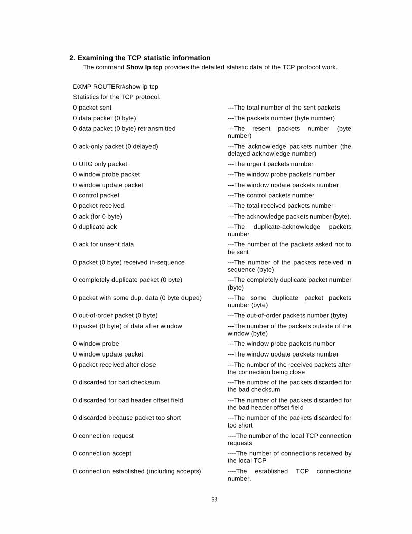
53
2. Examining the TCP statistic information The command Show Ip tcp provides the detailed statistic data of the TCP protocol work.
DXMP ROUTERr#show ip tcp
Statistics for the TCP protocol:
0 packet sent ---The total number of the sent packets
0 data packet (0 byte) ---The packets number (byte number)
0 data packet (0 byte) retransmitted ---The resent packets number (byte number)
0 ack-only packet (0 delayed) ---The acknowledge packets number (the delayed acknowledge number)
0 URG only packet ---The urgent packets number
0 window probe packet ---The window probe packets number
0 window update packet ---The window update packets number
0 control packet ---The control packets number
0 packet received ---The total received packets number
0 ack (for 0 byte) ---The acknowledge packets number (byte).
0 duplicate ack ---The duplicate-acknowledge packets number
0 ack for unsent data ---The number of the packets asked not to be sent
0 packet (0 byte) received in-sequence ---The number of the packets received in sequence (byte)
0 completely duplicate packet (0 byte) ---The completely duplicate packet number (byte)
0 packet with some dup. data (0 byte duped) ---The some duplicate packet packets number (byte)
0 out-of-order packet (0 byte) ---The out-of-order packets number (byte)
0 packet (0 byte) of data after window ---The number of the packets outside of the window (byte)
0 window probe ---The window probe packets number
0 window update packet ---The window update packets number
0 packet received after close ---The number of the received packets after the connection being close
0 discarded for bad checksum ---The number of the packets discarded for the bad checksum
0 discarded for bad header offset field ---The number of the packets discarded for the bad header offset field
0 discarded because packet too short ---The number of the packets discarded for too short
0 connection request ----The number of the local TCP connection requests
0 connection accept ----The number of connections received by the local TCP
0 connection established (including accepts) ----The established TCP connections number.
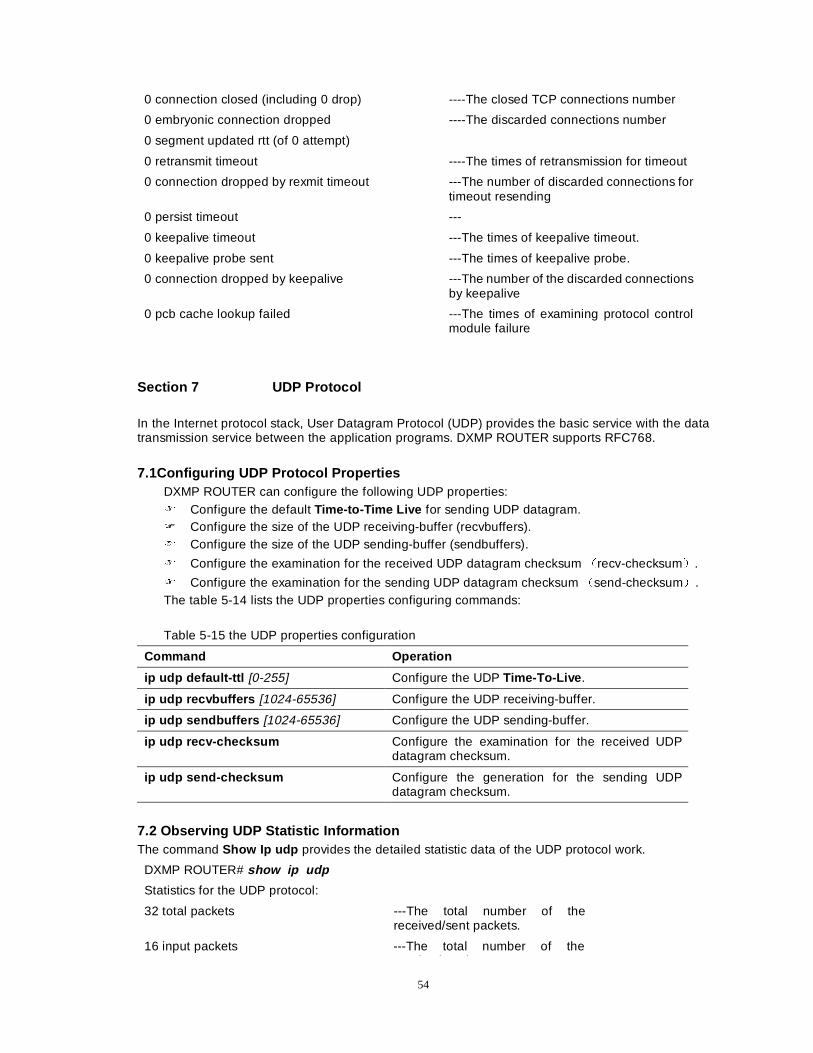
54
0 connection closed (including 0 drop) ----The closed TCP connections number
0 embryonic connection dropped ----The discarded connections number
0 segment updated rtt (of 0 attempt)
0 retransmit timeout ----The times of retransmission for timeout
0 connection dropped by rexmit timeout ---The number of discarded connections for timeout resending
0 persist timeout ---
0 keepalive timeout ---The times of keepalive timeout.
0 keepalive probe sent ---The times of keepalive probe.
0 connection dropped by keepalive ---The number of the discarded connections by keepalive
0 pcb cache lookup failed ---The times of examining protocol control module failure
Section 7 UDP Protocol In the Internet protocol stack, User Datagram Protocol (UDP) provides the basic service with the data transmission service between the application programs. DXMP ROUTER supports RFC768. 7.1Configuring UDP Protocol Properties
DXMP ROUTER can configure the following UDP properties: ) Configure the default Time-to-Time Live for sending UDP datagram. ) Configure the size of the UDP receiving-buffer (recvbuffers). ) Configure the size of the UDP sending-buffer (sendbuffers).
) Configure the examination for the received UDP datagram checksum Ärecv-checksumÅ.
) Configure the examination for the sending UDP datagram checksum Äsend-checksumÅ. The table 5-14 lists the UDP properties configuring commands: Table 5-15 the UDP properties configuration
Command Operation
ip udp default-ttl [0-255] Configure the UDP Time-To-Live .
ip udp recvbuffers [1024-65536] Configure the UDP receiving-buffer.
ip udp sendbuffers [1024-65536] Configure the UDP sending-buffer.
ip udp recv-checksum Configure the examination for the received UDP datagram checksum.
ip udp send-checksum Configure the generation for the sending UDP datagram checksum.
7.2 Observing UDP Statistic Information The command Show Ip udp provides the detailed statistic data of the UDP protocol work.
DXMP ROUTER# show ip udp
Statistics for the UDP protocol:
32 total packets ---The total number of the received/sent packets.
16 input packets ---The total number of the i d k t
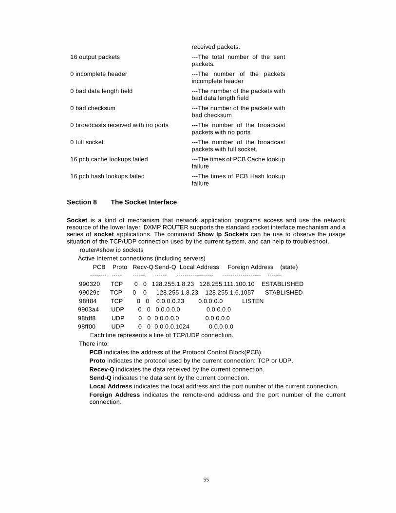
55
received packets.
16 output packets ---The total number of the sent packets.
0 incomplete header ---The number of the packets incomplete header
0 bad data length field ---The number of the packets with bad data length field
0 bad checksum ---The number of the packets with bad checksum
0 broadcasts received with no ports ---The number of the broadcast packets with no ports
0 full socket ---The number of the broadcast packets with full socket.
16 pcb cache lookups failed ---The times of PCB Cache lookup failure
16 pcb hash lookups failed ---The times of PCB Hash lookup failure
Section 8 The Socket Interface Socket is a kind of mechanism that network application programs access and use the network resource of the lower layer. DXMP ROUTER supports the standard socket interface mechanism and a series of socket applications. The command Show Ip Sockets can be use to observe the usage situation of the TCP/UDP connection used by the current system, and can help to troubleshoot.
router#show ip sockets Active Internet connections (including servers)
PCB Proto Recv-Q Send-Q Local Address Foreign Address (state) -------- ----- ------ ------ ------------------ ------------------- -------
990320 TCP 0 0 128.255.1.8.23 128.255.111.100.10 ESTABLISHED 99029c TCP 0 0 128.255.1.8.23 128.255.1.6.1057 STABLISHED 98ff84 TCP 0 0 0.0.0.0.23 0.0.0.0.0 LISTEN 9903a4 UDP 0 0 0.0.0.0.0 0.0.0.0.0 98fdf8 UDP 0 0 0.0.0.0.0 0.0.0.0.0 98ff00 UDP 0 0 0.0.0.0.1024 0.0.0.0.0
Each line represents a line of TCP/UDP connection. There into:
PCB indicates the address of the Protocol Control Block(PCB). Proto indicates the protocol used by the current connection: TCP or UDP. Recev-Q indicates the data received by the current connection. Send-Q indicates the data sent by the current connection. Local Address indicates the local address and the port number of the current connection. Foreign Address indicates the remote-end address and the port number of the current connection.
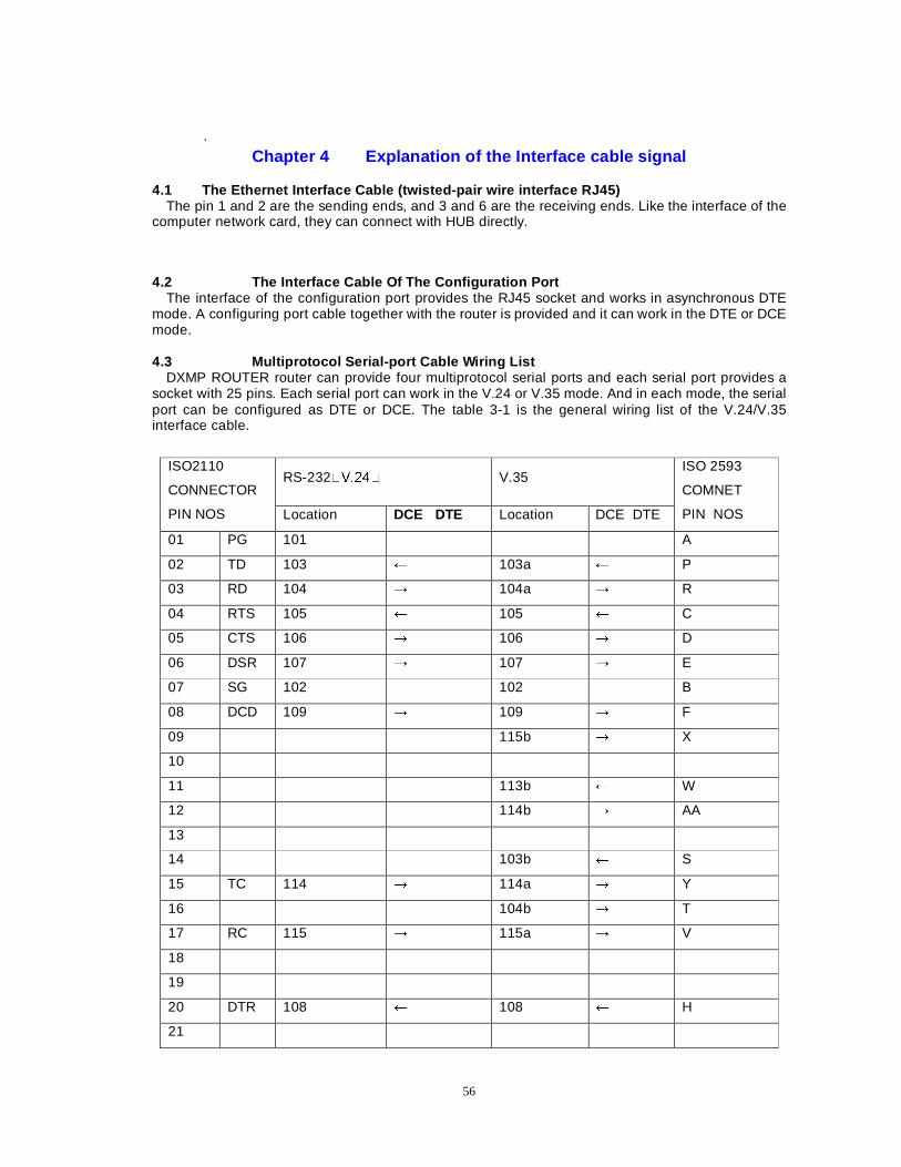
56
.
Chapter 4 Explanation of the Interface cable signal 4.1 The Ethernet Interface Cable (twisted-pair wire interface RJ45)
The pin 1 and 2 are the sending ends, and 3 and 6 are the receiving ends. Like the interface of the computer network card, they can connect with HUB directly.
4.2 The Interface Cable Of The Configuration Port The interface of the configuration port provides the RJ45 socket and works in asynchronous DTE
mode. A configuring port cable together with the router is provided and it can work in the DTE or DCE mode. 4.3 Multiprotocol Serial-port Cable Wiring List
DXMP ROUTER router can provide four multiprotocol serial ports and each serial port provides a socket with 25 pins. Each serial port can work in the V.24 or V.35 mode. And in each mode, the serial port can be configured as DTE or DCE. The table 3-1 is the general wiring list of the V.24/V.35 interface cable.
RS-232�9���� V.35 ISO2110
CONNECTOR
PIN NOS Location DCE DTE Location DCE DTE
ISO 2593
COMNET
PIN NOS
01 PG 101 A
02 TD 103 8 103a 8 P
03 RD 104 : 104a : R
04 RTS 105 8 105 8 C
05 CTS 106 : 106 : D
06 DSR 107 : 107 : E
07 SG 102 102 B
08 DCD 109 : 109 : F
09 115b : X
10
11 113b 8 W
12 114b : AA
13
14 103b 8 S
15 TC 114 : 114a : Y
16 104b : T
17 RC 115 : 115a : V
18
19
20 DTR 108 8 108 8 H
21

57
22
23
24 EXC 113 8 113a 8 U
25
Table 4-1 the general wiring list of the V.24/V.35 interface cable
58
Chapter 5 WAN Protocols Configuration Dax-Maipu supports the following familiar WAN protocols: PPP, HDLC, X.25, LAPB, X.25, frame relay, SLIP, ISDN and dial-up connection. This chapter mainly describes how to configure Dax-Maipu to connect with WAN (ISDN and dial-up connection can refer to Chapter 6). The main contents of this chapter are as follows: zz PPP protocol zz HDLC protocol zz SLIP protocol zz TCP/IP header compression zz X.25 protocol zz Frame Relay protocol
Section 1 PPP Protocol The main contents of this section are as follows: zz Brief Introduction of PPP zz Description of basic PPP instructions zz PPP configuration examples zz Configuring PPP authentication zz Monitor and debug PPP information zz PPP address pool zz PPP multilink zz PPP realiable-link zz PPP data compression 1.1 Brief Introduction of PPP
PPP protocol is a kind of data link layer protocol to transmit network layer packets on the connection from point to point. PPP includes Link Control Protocol (LCP), Network Control Protocol (NCP), Authentication Protocol (PAP and CHAP), and it can support synchronous/asynchronous line. PPP be applicable to serial systems with different properties to transmit many kinds of network layer protocol data. It’s a universal method to connect various kinds of hosts, bridges and routers.
PPP is mainly composed of the following three components: The method to encapsulate many kinds of network protocol datagrams; The Link Control Protocol (LCP) used to establish, configure and test the data link connection; A group of Network Control Protocols (NCP) used to establish and configure different network layer protocols.
1.2 Description of basic PPP instructions 1) Interface commands: router1(config-if-XXX)#ppp ?
Command Description
ppp ac PPP frame address and compression of control field ppp accounting Configure the accounting method of PPP
connection. ppp authentication Configure the authentication method (CHAP/PAP)
of PPP connection. ppp callback ------ppp callback accept ------ppp callback request
Configure the callback operation. Configure it as the receiving side. Configured it as the originate side.
ppp chap hostname Configure CHAP authentiction parameters. ppp multilink Configure the multilink binding of interface. ppp compression PPP compression protocol (predictor/stacker)
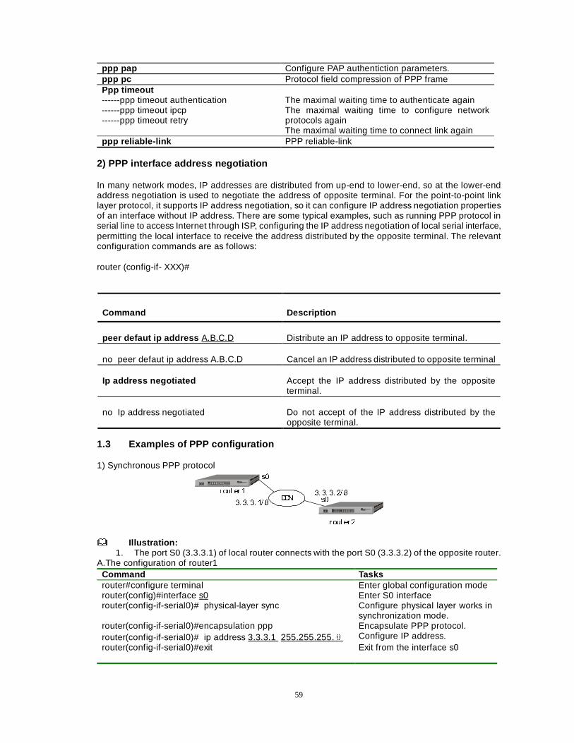
59
ppp pap Configure PAP authentiction parameters. ppp pc Protocol field compression of PPP frame Ppp timeout ------ppp timeout authentication ------ppp timeout ipcp ------ppp timeout retry
The maximal waiting time to authenticate again The maximal waiting time to configure network protocols again The maximal waiting time to connect link again
ppp reliable-link PPP reliable-link
2) PPP interface address negotiation
In many network modes, IP addresses are distributed from up-end to lower-end, so at the lower-end address negotiation is used to negotiate the address of opposite terminal. For the point-to-point link layer protocol, it supports IP address negotiation, so it can configure IP address negotiation properties of an interface without IP address. There are some typical examples, such as running PPP protocol in serial line to access Internet through ISP, configuring the IP address negotiation of local serial interface, permitting the local interface to receive the address distributed by the opposite terminal. The relevant configuration commands are as follows:
router (config-if- XXX)#
Command Description
peer defaut ip address A.B.C.D Distribute an IP address to opposite terminal.
no peer defaut ip address A.B.C.D Cancel an IP address distributed to opposite terminal
Ip address negotiated Accept the IP address distributed by the opposite terminal.
no Ip address negotiated Do not accept of the IP address distributed by the opposite terminal.
1.3 Examples of PPP configuration 1) Synchronous PPP protocol
''1
URXW HU �
U RXW HU �
V�
V��� �� �� �� �
�� �� �� �� �
Illustration:
1. The port S0 (3.3.3.1) of local router connects with the port S0 (3.3.3.2) of the opposite router. A.The configuration of router1
Command Tasks router#configure terminal router(config)#interface s0
Enter global configuration mode Enter S0 interface
router(config-if-serial0)# physical-layer sync Configure physical layer works in synchronization mode.
router(config-if-serial0)#encapsulation ppp Encapsulate PPP protocol. router(config-if-serial0)# ip address 3.3.3.1 255.255.255.Ì Configure IP address. router(config-if-serial0)#exit Exit from the interface s0
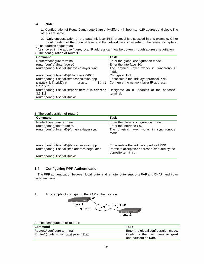
60
Note:
1. Configuration of Router2 and router1 are only different in host name,IP address and clock. The others are same.
2. Only encapsulation of the data link layer PPP protocol is discussed in this example. Other configuration of the physical layer and the network layers can refer to the relevant chapters.
2) The address negotiation As showed in the above figure, local IP address can now be gotten through address negotiation.
A. The configuration of router1: Command Task Router#configure terminal Enter the global configuration mode. router(config)#interface s0 Enter the interface S0. router(config-if-serial0)#physical-layer sync The physical layer works in synchronous
mode. router(config-if-serial0)#clock rate 64000 Configure clock. router(config-if-serial0)#encapsulation ppp Encapsulate the link layer protocol PPP. rou ter(con f ig-if-serial0 )# ip address 3 .3.3 .1 255.255 .255 .0
Configure the network layer IP address.
router(config-if-serial0)#peer defaut ip address 3.3.3.2
Designate an IP address of the opposite terminal.
router(config-if-serial0)#exit
B. The configuration of router2: Command Task Router#configure terminal Enter the global configuration mode. router(config)#interface s0 Enter the interface S0. router(config-if-serial0)#physical-layer sync The physical layer works in synchronous
mode.
router(config-if-serial0)#encapsulation ppp Encapsulate the link layer protocol PPP. router(config-if-serial0)#ip address negotiated Permit to accept the address distributed by the
opposite terminal. router(config-if-serial0)#exit
1.4 Configuring PPP Authentication
The PPP authentication between local router and remote router supports PAP and CHAP, and it can be bidirectional.
1. An example of configuring the PAP authentication
''1
URXWHU�
URXWHU�
V�
V����������
���������
A. The configuration of router1: Command Task Router1#configure terminal Enter the global configuration mode. Router1(config)#user goat pass 0 Dax Configure the user name as goat
and passord as Dax.
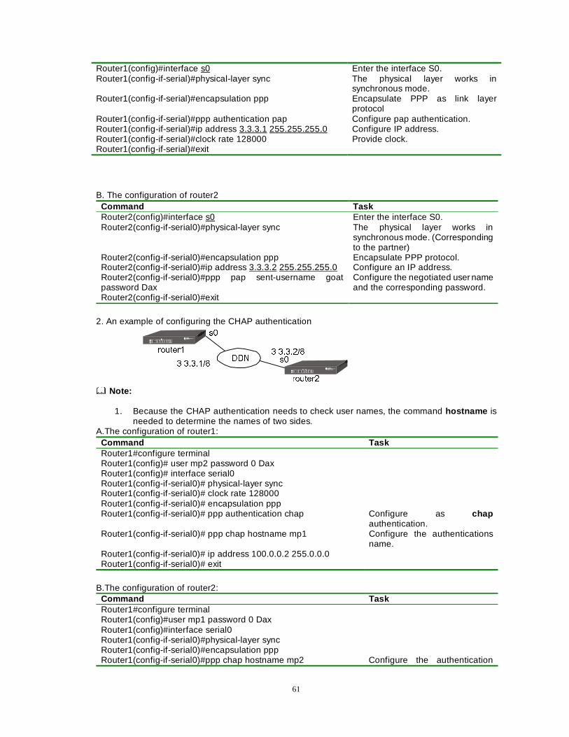
61
Router1(config)#interface s0 Enter the interface S0. Router1(config-if-serial)#physical-layer sync The physical layer works in
synchronous mode. Router1(config-if-serial)#encapsulation ppp Encapsulate PPP as link layer
protocol Router1(config-if-serial)#ppp authentication pap Configure pap authentication. Router1(config-if-serial)#ip address 3.3.3.1 255.255.255.0 Configure IP address. Router1(config-if-serial)#clock rate 128000 Provide clock. Router1(config-if-serial)#exit
B. The configuration of router2 Command Task Router2(config)#interface s0 Enter the interface S0. Router2(config-if-serial0)#physical-layer sync The physical layer works in
synchronous mode. (Corresponding to the partner)
Router2(config-if-serial0)#encapsulation ppp Encapsulate PPP protocol. Router2(config-if-serial0)#ip address 3.3.3.2 255.255.255.0 Configure an IP address. Router2(config-if-serial0)#ppp pap sent-username goat password Dax
Configure the negotiated user name and the corresponding password.
Router2(config-if-serial0)#exit
2. An example of configuring the CHAP authentication
''1
URXWHU�
URXWHU�
V�
V����������
���������
Note:
1. Because the CHAP authentication needs to check user names, the command hostname is
needed to determine the names of two sides. A.The configuration of router1:
Command Task Router1#configure terminal Router1(config)# user mp2 password 0 Dax Router1(config)# interface serial0 Router1(config-if-serial0)# physical-layer sync Router1(config-if-serial0)# clock rate 128000 Router1(config-if-serial0)# encapsulation ppp Router1(config-if-serial0)# ppp authentication chap Configure as chap
authentication. Router1(config-if-serial0)# ppp chap hostname mp1 Configure the authentications
name. Router1(config-if-serial0)# ip address 100.0.0.2 255.0.0.0 Router1(config-if-serial0)# exit
B.The configuration of router2: Command Task Router1#configure terminal Router1(config)#user mp1 password 0 Dax Router1(config)#interface serial0 Router1(config-if-serial0)#physical-layer sync Router1(config-if-serial0)#encapsulation ppp Router1(config-if-serial0)#ppp chap hostname mp2 Configure the authentication
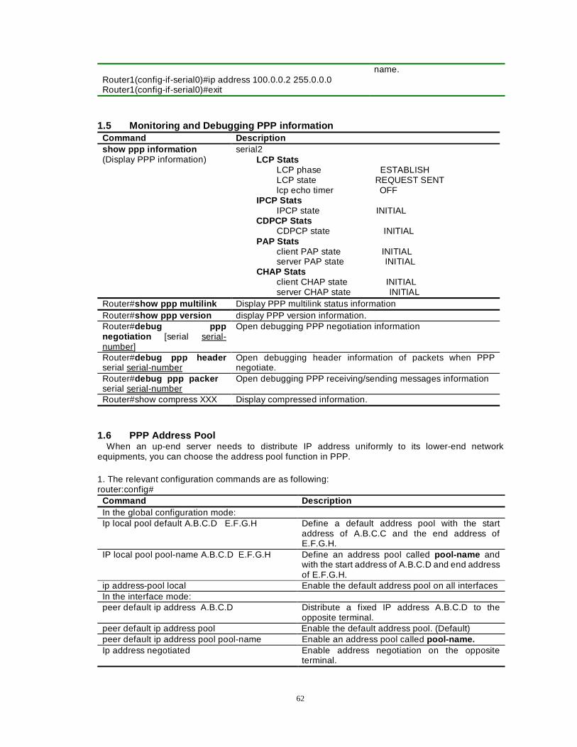
62
name. Router1(config-if-serial0)#ip address 100.0.0.2 255.0.0.0 Router1(config-if-serial0)#exit
1.5 Monitoring and Debugging PPP information Command Description show ppp information (Display PPP information)
serial2 LCP Stats LCP phase ESTABLISH LCP state REQUEST SENT lcp echo timer OFF IPCP Stats IPCP state INITIAL CDPCP Stats CDPCP state INITIAL PAP Stats client PAP state INITIAL server PAP state INITIAL CHAP Stats client CHAP state INITIAL server CHAP state INITIAL
Router#show ppp multilink Display PPP multilink status information Router#show ppp version display PPP version information. Router#debug ppp negotiation [serial serial-number]
Open debugging PPP negotiation information
Router#debug ppp header serial serial-number
Open debugging header information of packets when PPP negotiate.
Router#debug ppp packer serial serial-number
Open debugging PPP receiving/sending messages information
Router#show compress XXX Display compressed information.
1.6 PPP Address Pool When an up-end server needs to distribute IP address uniformly to its lower-end network
equipments, you can choose the address pool function in PPP.
1. The relevant configuration commands are as following: router:config#
Command Description In the global configuration mode: Ip local pool default A.B.C.D E.F.G.H Define a default address pool with the start
address of A.B.C.C and the end address of E.F.G.H.
IP local pool pool-name A.B.C.D E.F.G.H Define an address pool called pool-name and with the start address of A.B.C.D and end address of E.F.G.H.
ip address-pool local Enable the default address pool on all interfaces In the interface mode: peer default ip address A.B.C.D Distribute a fixed IP address A.B.C.D to the
opposite terminal. peer default ip address pool Enable the default address pool. (Default) peer default ip address pool pool-name Enable an address pool called pool-name. Ip address negotiated Enable address negotiation on the opposite
terminal.
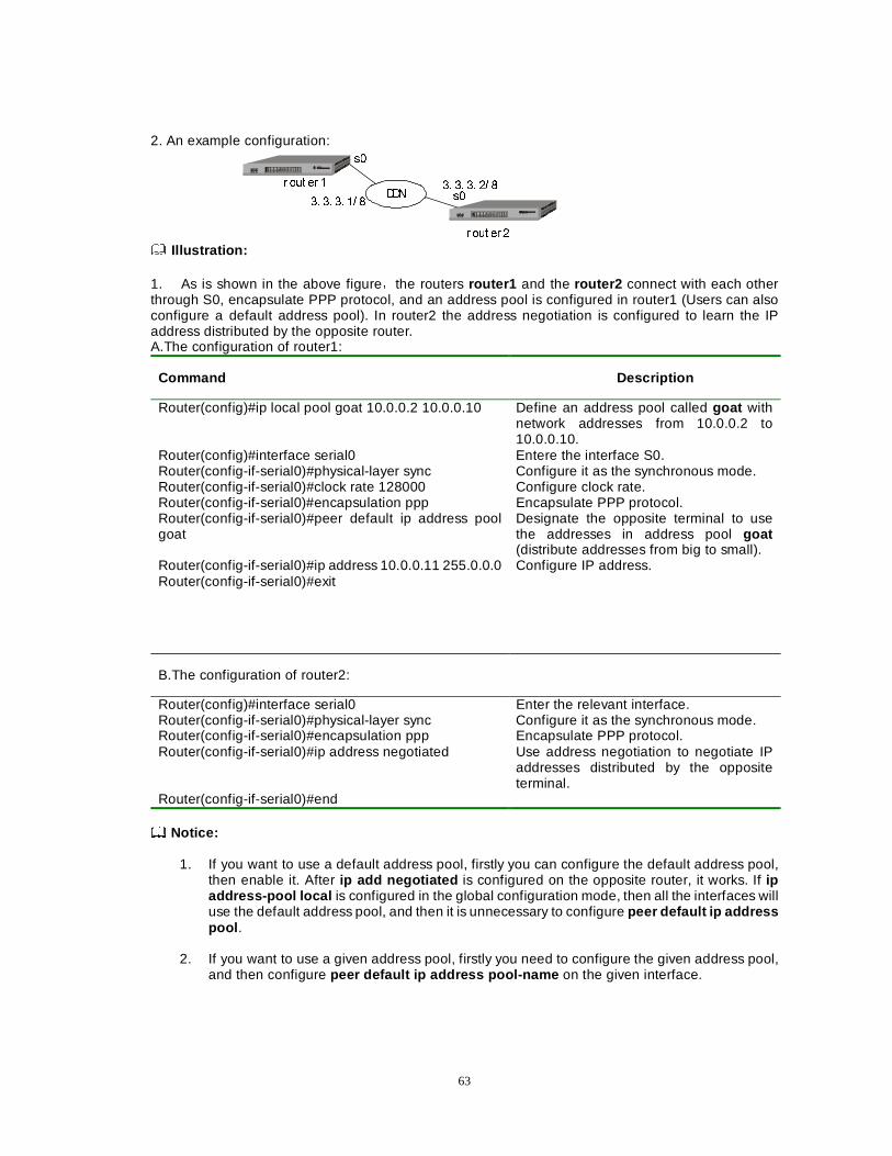
63
2. An example configuration:
''1
URXW HU �
U RXW HU �
V�
V��� �� �� �� �
�� �� �� �� �
Illustration:
1. As is shown in the above figureÈthe routers router1 and the router2 connect with each other through S0, encapsulate PPP protocol, and an address pool is configured in router1 (Users can also configure a default address pool). In router2 the address negotiation is configured to learn the IP address distributed by the opposite router. A.The configuration of router1:
Command Description
Router(config)#ip local pool goat 10.0.0.2 10.0.0.10 Define an address pool called goat with network addresses from 10.0.0.2 to 10.0.0.10.
Router(config)#interface serial0 Entere the interface S0. Router(config-if-serial0)#physical-layer sync Configure it as the synchronous mode. Router(config-if-serial0)#clock rate 128000 Configure clock rate. Router(config-if-serial0)#encapsulation ppp Encapsulate PPP protocol. Router(config-if-serial0)#peer default ip address pool goat
Designate the opposite terminal to use the addresses in address pool goat (distribute addresses from big to small).
Router(config-if-serial0)#ip address 10.0.0.11 255.0.0.0 Router(config-if-serial0)#exit
Configure IP address.
B.The configuration of router2:
Router(config)#interface serial0 Enter the relevant interface. Router(config-if-serial0)#physical-layer sync Configure it as the synchronous mode. Router(config-if-serial0)#encapsulation ppp Encapsulate PPP protocol. Router(config-if-serial0)#ip address negotiated Use address negotiation to negotiate IP
addresses distributed by the opposite terminal.
Router(config-if-serial0)#end Notice:
1. If you want to use a default address pool, firstly you can configure the default address pool,
then enable it. After ip add negotiated is configured on the opposite router, it works. If ip address-pool local is configured in the global configuration mode, then all the interfaces will use the default address pool, and then it is unnecessary to configure peer default ip address pool .
2. If you want to use a given address pool, firstly you need to configure the given address pool,
and then configure peer default ip address pool-name on the given interface.
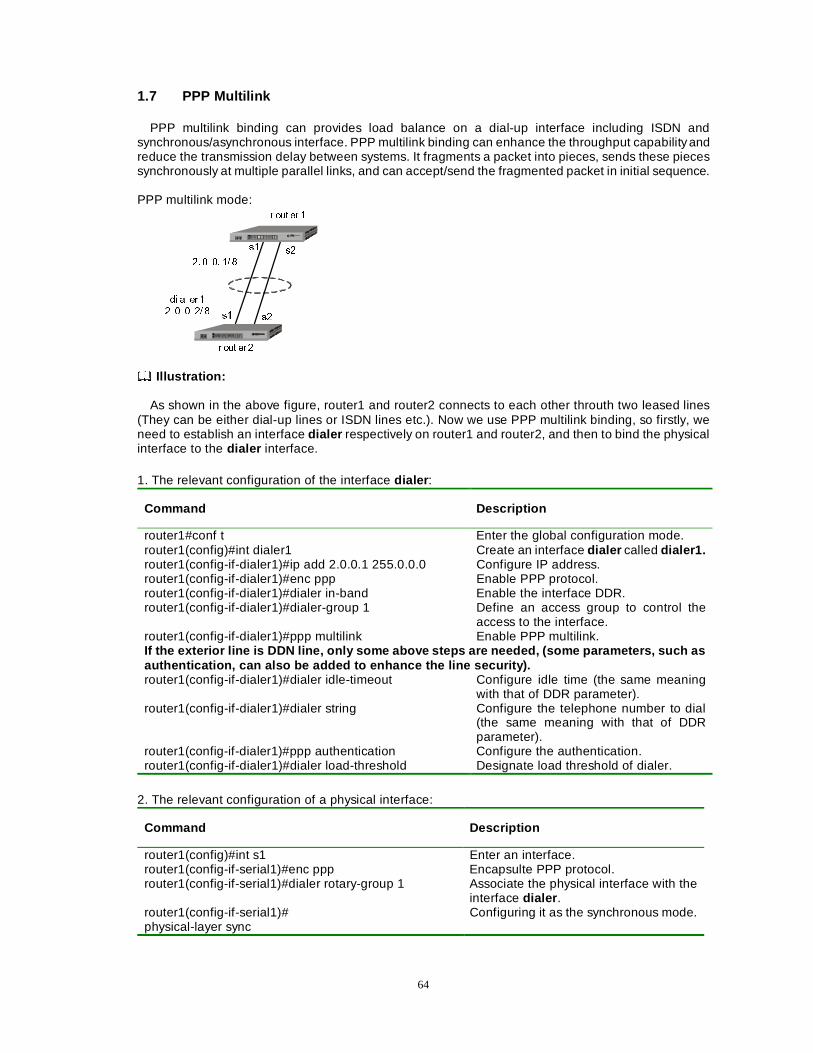
64
1.7 PPP Multilink
PPP multilink binding can provides load balance on a dial-up interface including ISDN and synchronous/asynchronous interface. PPP multilink binding can enhance the throughput capability and reduce the transmission delay between systems. It fragments a packet into pieces, sends these pieces synchronously at multiple parallel links, and can accept/send the fragmented packet in initial sequence. PPP multilink mode:
U RXW HU �
U RXW HU �
V�
V�V�
V�
�� �� �� �� �
GL DO HU �
�� �� �� �� �
Illustration:
As shown in the above figure, router1 and router2 connects to each other throuth two leased lines
(They can be either dial-up lines or ISDN lines etc.). Now we use PPP multilink binding, so firstly, we need to establish an interface dialer respectively on router1 and router2, and then to bind the physical interface to the dialer interface.
1. The relevant configuration of the interface dialer :
Command Description
router1#conf t Enter the global configuration mode. router1(config)#int dialer1 Create an interface dialer called dialer1. router1(config-if-dialer1)#ip add 2.0.0.1 255.0.0.0 Configure IP address. router1(config-if-dialer1)#enc ppp Enable PPP protocol. router1(config-if-dialer1)#dialer in-band Enable the interface DDR. router1(config-if-dialer1)#dialer-group 1 Define an access group to control the
access to the interface. router1(config-if-dialer1)#ppp multilink Enable PPP multilink. If the exterior line is DDN line, only some above steps are needed, (some parameters, such as authentication, can also be added to enhance the line security). router1(config-if-dialer1)#dialer idle-timeout Configure idle time (the same meaning
with that of DDR parameter). router1(config-if-dialer1)#dialer string Configure the telephone number to dial
(the same meaning with that of DDR parameter).
router1(config-if-dialer1)#ppp authentication Configure the authentication. router1(config-if-dialer1)#dialer load-threshold Designate load threshold of dialer.
2. The relevant configuration of a physical interface:
Command Description
router1(config)#int s1 Enter an interface. router1(config-if-serial1)#enc ppp Encapsulte PPP protocol. router1(config-if-serial1)#dialer rotary-group 1 Associate the physical interface with the
interface dialer . router1(config-if-serial1)# physical-layer sync
Configuring it as the synchronous mode.
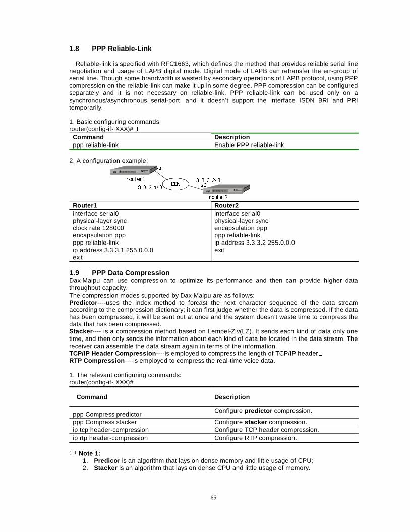
65
1.8 PPP Reliable-Link
Reliable-link is specified with RFC1663, which defines the method that provides reliable serial line negotiation and usage of LAPB digital mode. Digital mode of LAPB can retransfer the err-group of serial line. Though some brandwidth is wasted by secondary operations of LAPB protocol, using PPP compression on the reliable-link can make it up in some degree. PPP compression can be configured separately and it is not necessary on reliable-link. PPP reliable-link can be used only on a synchronous/asynchronous serial-port, and it doesn’t support the interface ISDN BRI and PRI temporarily. 1. Basic configuring commands router(config-if- XXX)#�
Command Description ppp reliable-link Enable PPP reliable-link.
2. A configuration example:
''1
U RXW HU �
U RXW HU �
V�
V��� �� �� �� �
�� �� �� �� �
Router1 Router2 interface serial0 physical-layer sync clock rate 128000 encapsulation ppp ppp reliable-link ip address 3.3.3.1 255.0.0.0 exit
interface serial0 physical-layer sync encapsulation ppp ppp reliable-link ip address 3.3.3.2 255.0.0.0 exit
1.9 PPP Data Compression Dax-Maipu can use compression to optimize its performance and then can provide higher data throughput capacity. The compression modes supported by Dax-Maipu are as follows: Predictor ----uses the index method to forcast the next character sequence of the data stream according to the compression dictionary; it can first judge whether the data is compressed. If the data has been compressed, it will be sent out at once and the system doesn’t waste time to compress the data that has been compressed. Stacker ---- is a compression method based on Lempel-Ziv(LZ). It sends each kind of data only one time, and then only sends the information about each kind of data be located in the data stream. The receiver can assemble the data stream again in terms of the information. TCP/IP Header Compression ----is employed to compress the length of TCP/IP header� RTP Compression ----is employed to compress the real-time voice data. 1. The relevant configuring commands: router(config-if- XXX)#
Command Description
ppp Compress predictor Configure predictor compression.
ppp Compress stacker Configure stacker compression. ip tcp header-compression Configure TCP header compression. ip rtp header-compression Configure RTP compression.
Note 1:
1. Predicor is an algorithm that lays on dense memory and little usage of CPU; 2. Stacker is an algorithm that lays on dense CPU and little usage of memory.
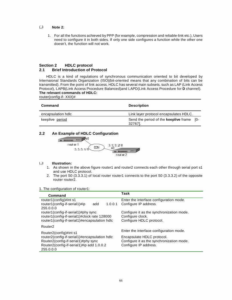
66
Note 2: 1. For all the functions achieved by PPP (for example, compression and reliable-link etc.), Users
need to configure it in both sides. If only one side configures a function while the other one doesn’t, the function will not work.
Section 2 HDLC protocol 2.1 Brief Introduction of Protocol
HDLC is a kind of regulations of synchronous communication oriented to bit developed by Internaional Standards Organization (ISO)(bit-oriented means that any combination of bits can be transmitted). From the point of link access, HDLC has several main subsets, such as LAP (Link Access Protocol), LAPB(Link Access Procedure Balanced)and LAPD(Link Access Procedure for D channel). The relevant commands of HDLC: router(config-if- XXX)#
Command Description
encapsulation hdlc Link layer protocol encapsulates HDLC.
keeplive period Send the period of the keeplive frame [0-32767].
2.2 An Example of HDLC Configuration
''1
U RXW HU �
U RXW HU �
V�
V��� �� �� �� �
�� �� �� �� �
Illustration:
1. As shown in the above figure router1 and router2 connects each other through serial port s1 and use HDLC protocol.
2. The port S0 (3.3.3.1) of local router router1 connects to the port S0 (3.3.3.2) of the opposite router router2.
1. The configuration of router1:
Command Task
router1(config)#int s1 Enter the interface configuration mode. router1(config-if-serial1)#ip add 1.0.0.1 255.0.0.0
Configure IP address.
router1(config-if-serial1)#phy sync Configure it as the synchronization mode. router1(config-if-serial1)#clock rate 128000 Configure clock. router1(config-if-serial1)#encapsulation hdlc Configure HDLC protocol.
Router2
Router2(config)#int s1 Enter the interface configuration mode.
router2(config-if-serial1)#encapsulation hdlc Encapsulate HDLC protocol. Router2(config-if-serial1)#phy sync Configure it as the synchronization mode. Router2(config-if-serial1)#ip add 1.0.0.2 255.0.0.0
Configure IP address.
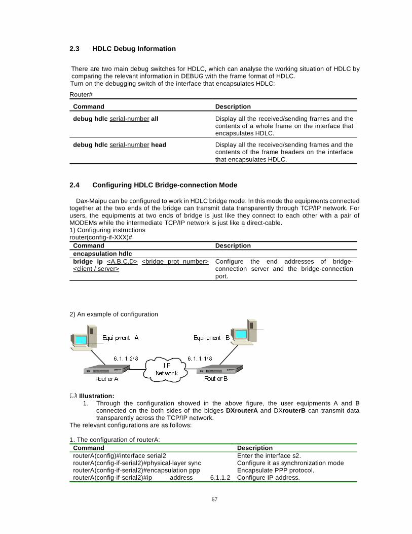
67
2.3 HDLC Debug Information
There are two main debug switches for HDLC, which can analyse the working situation of HDLC by comparing the relevant information in DEBUG with the frame format of HDLC. Turn on the debugging switch of the interface that encapsulates HDLC:
Router#
Command Description
debug hdlc serial-number all Display all the received/sending frames and the contents of a whole frame on the interface that encapsulates HDLC.
debug hdlc serial-number head Display all the received/sending frames and the contents of the frame headers on the interface that encapsulates HDLC.
2.4 Configuring HDLC Bridge-connection Mode
Dax-Maipu can be configured to work in HDLC bridge mode. In this mode the equipments connected together at the two ends of the bridge can transmit data transparently through TCP/IP network. For users, the equipments at two ends of bridge is just like they connect to each other with a pair of MODEMs while the intermediate TCP/IP network is just like a direct-cable. 1) Configuring instructions router(config-if-XXX)#
Command Description encapsulation hdlc bridge ip <A.B.C.D> <bridge prot number> <client / server>
Configure the end addresses of bridge-connection server and the bridge-connection port.
2) An example of configuration
�� �� �� �� � �� �� �� �� �
, 3
1HW ZRU N
(TXL SPHQW $ (TXL SPHQW %
5RXW HU $ 5RXW HU %
Illustration:
1. Through the configuration showed in the above figure, the user equipments A and B connected on the both sides of the bidges DXrouterA and DXrouterB can transmit data transparently across the TCP/IP network.
The relevant configurations are as follows: 1. The configuration of routerA:
Command Description routerA(config)#interface serial2 Enter the interface s2. routerA(config-if-serial2)#physical-layer sync Configure it as synchronization mode routerA(config-if-serial2)#encapsulation ppp Encapsulate PPP protocol. routerA(config-if-serial2)#ip address 6.1.1.2 Configure IP address.
68
255.255.255.252 routerA(config-if-serial2)#exit Go back to global configuration mode. routerA(config)#interface serial3 Enter the interface s3. routerA(config-if-serial3)#physical-layer sync Encapsulate the synchronization mode. routerA(config-if-serial3)#clock rate 128000 Configure the clock as 128K. routerA(config-if-serial3)#encapsulation hdlc Encapsulate HDLC protocol. routerA(config-if-serial3)#bridge ip 6.1.1.1 5000 client The IP of the bridge-connection server,
the port number 5000, the client end routerA(config-if-serial3)#exit Finish the configuration.
2. The configuration of routerB
Command Description routerB(config)#interface serial2 routerB(config-if-serial2)# physical-layer sync Configure it as the synchronization
mode. routerB(config-if-serial2)#clock rate 128000 Configure the clock as 128K. routerB(config-if-serial2)#encapsulation ppp Encapsulate PPP protocol. routerB(config-if-serial2)#ip address 6.1.1.1 255.255.255.252
Configure IP address.
routerB(config-if-serial2)#exit Exit from the interface mode. routerB(config)#interface serial0 Enter the port s0 mode. routerB(config-if-serial0)#physical-layer sync Configure it as synchronization mode. routerB(config-if-serial0)#encapsulation hdlc Configure HDLC encapsulation. routerB(config-if-serial0)#bridge ip 6.1.1.1 5000 server Configure the server with a port 5000. routerB(config-if-serial0)#exit Finish configuration.
Note:
1. In the above configuration, the dxrouterA is used as the client end while the dxrouterB is used as the server end; both of the bridge port numbers are set as 5000. The s2 port of dxrouterA and the s2 port of dxrouterB connect to the TCP/IP network respectively. The port s3 and port s0 are used as the interface of bridge-connection to connect user equipments, and then they enable the user equipments to transmit data transparently through TCP/IP network.
3) Displaying Information
Through the command “show interface” provided by the router, users could examine the current connection status of the bridge. For example: dxrouteA#show interface serial3 serial (unit number 3): Flags: (0x80f0) DOWN POINT-TO-POINT MULTICAST RUNNING Type: HDLC Metric is 0 Maximum Transfer Unit size is 1500 0 packets received; 0 packets sent 0 multicast packets received 0 multicast packets sent 5 input errors; 0 output errors 0 collisions; 0 dropped hdlc version: v1.27
hdlc bridge client: 6.1.1.1,5000, connect The bridge is at the status of connected. rxFrames 1744, rxChars 74436 txFrames 1738, txChars 74410 rxNoOctet 0, rxAbtErrs 0, rxCrcErrs 0 rxOverrun 0, rxLenErrs 0, txUnderrun 0 DCD=up DSR=up DTR=up RTS=up CTS=up TxC=up
rate=128000 bps
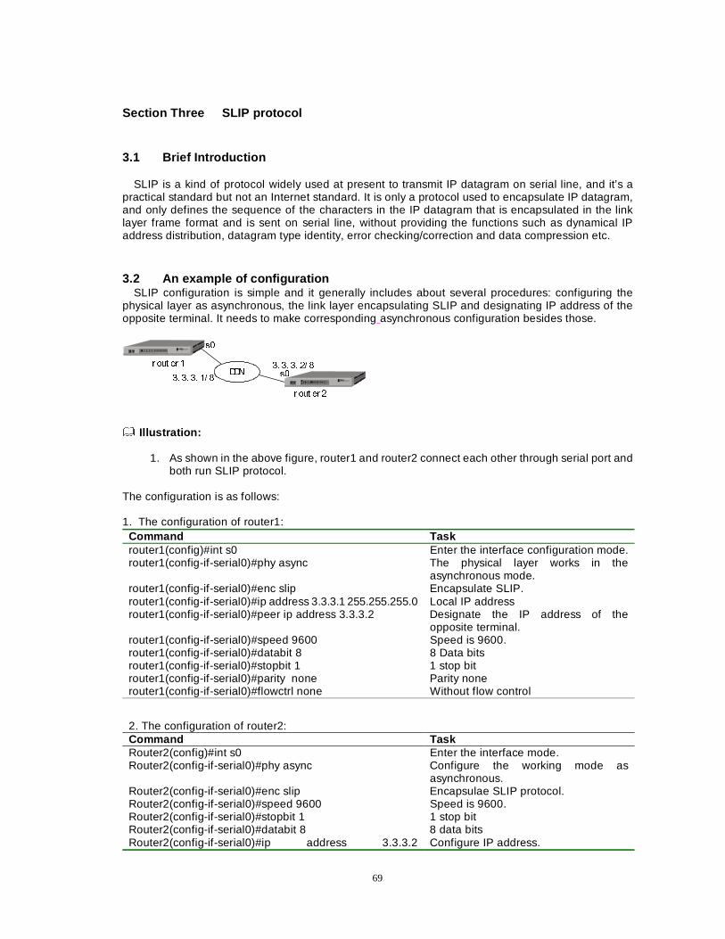
69
Section Three SLIP protocol
3.1 Brief Introduction SLIP is a kind of protocol widely used at present to transmit IP datagram on serial line, and it’s a
practical standard but not an Internet standard. It is only a protocol used to encapsulate IP datagram, and only defines the sequence of the characters in the IP datagram that is encapsulated in the link layer frame format and is sent on serial line, without providing the functions such as dynamical IP address distribution, datagram type identity, error checking/correction and data compression etc.
3.2 An example of configuration SLIP configuration is simple and it generally includes about several procedures: configuring the
physical layer as asynchronous, the link layer encapsulating SLIP and designating IP address of the opposite terminal. It needs to make corresponding asynchronous configuration besides those.
''1
URXW HU �
U RXW HU �
V�
V��� �� �� �� �
�� �� �� �� �
Illustration:
1. As shown in the above figure, router1 and router2 connect each other through serial port and
both run SLIP protocol. The configuration is as follows: 1. The configuration of router1:
Command Task router1(config)#int s0 Enter the interface configuration mode. router1(config-if-serial0)#phy async The physical layer works in the
asynchronous mode. router1(config-if-serial0)#enc slip Encapsulate SLIP. router1(config-if-serial0)#ip address 3.3.3.1 255.255.255.0 Local IP address router1(config-if-serial0)#peer ip address 3.3.3.2 Designate the IP address of the
opposite terminal. router1(config-if-serial0)#speed 9600 Speed is 9600. router1(config-if-serial0)#databit 8 8 Data bits router1(config-if-serial0)#stopbit 1 1 stop bit router1(config-if-serial0)#parity none Parity none router1(config-if-serial0)#flowctrl none Without flow control
2. The configuration of router2:
Command Task Router2(config)#int s0 Enter the interface mode. Router2(config-if-serial0)#phy async Configure the working mode as
asynchronous. Router2(config-if-serial0)#enc slip Encapsulae SLIP protocol. Router2(config-if-serial0)#speed 9600 Speed is 9600. Router2(config-if-serial0)#stopbit 1 1 stop bit Router2(config-if-serial0)#databit 8 8 data bits Router2(config-if-serial0)#ip address 3.3.3.2 Configure IP address.
70
255.255.255.0 Router2(config-if-serial0)#peer ip address 3.3.3.1 Designate the IP address of the
opposite terminal. Router2(config-if-serial0)#parity none Parity none Router2(config-if-serial0)#flowctrl none Without flow control
Note:
1. Peer ip add A.B.C.D is used to designate the IP address of the opposite side.
Section 4 TCP/IP Packet Header Compression TCP packet header compression uses the algorithm van Jacobson , which is defined in the RFC 1144. It’s suitable for TCP/IP data stream with small packets (for example, the telnet session packet). TCP/IP packet header compression reduces additional cost because of transferring big TCP/IP packet header in WAN. TCP/IP packet header compression aims at protocols and it only compresses TCP/IP packet header. So the frame header of the second layer will not be changed. The data frame whose TCP/IP packet header has been compressed will be transmitted on the WAN link. In other words, TCP/IP packet header compression is more useful with the minitype packets that only have several bytes (such as a telnet packet). The packet header compression protocols supported by Dax-Maipu are as follows: X25 protocol, Frame-relay protocol, PPP protocol and HDLC protocol. This kind of packet can also be applied to the dial-up WAN link protocol. Because data compression wll bring additional process, packet header compression is usually used on the low-speed link, for example, the 64Kb/S link. The configurition commands are as follows: router (config-if-XXX)#
Command Description
enc ppp Encapsulate ppp. (DXMP ROUTER supports the TCP packet-header compression of x25.frame-relay.hdlc.ppp )
ip tcp header-compression Encapsulate TCP packet header compressionÄ Ip tcp header-compression passive The function of the keyword “passive”is that the TCP
packets will be compressed if received packets of the interface are compressed. If the parameter “passive” isn’t designated, router will compress all the data streams.
Section 5 X.25 Protocol This section mainly introduces how to configure X.25 protocol on Dax-Maipu and how to run various X25 parameters so as to achieve the application of Dax-Maipu in X.25 network.
The main contents of this section are as follows: zz Brief introduction of X.25 zz Description of basic X.25 configurition zz The typical examples of X.25 configurition zz Debugging/monitoring X.25 zz The X.25 sub-interface zz Examples of X.25 sub-interface configurition
71
5.1 Brief Introduction of X.25
When DXMP ROUTER router is used to connect with X.25 network or another router encapsulating X.25 through the leased line, the X.25 protocol and LAPB protocol need be configured on the WAN port of router.
5.2 Description of basic X.25 configuration A. The configuring commands of X.25 router(config-if-XXX)#x25 ?
Command Description
Address <X.121 address> Configure the X.121 address of the interface.
Dce Work in X.25 DCE mode
Dte Work in X.25 DTE mode
hold-queue <number> Configure the hold-queue length of virtual circuit group.
htc <Virtual Circuit number> Configure the highest bidirectional virtual circuit.
idle <Minutes> Configure the idle time of encapsulated virtual circuit.
ips < bytes (power of 2)> Configure the size of the maximal input group.
ltc <virtual circuit number> Configure the lowest-bidirectional virtual circuit.
map ip/ compressedtcp < A.B.C.D> <X.121 Addr>< broadcast/ negotiate-disable/ <CR> >
Establish the mapping from IP address to X.121 address.
modulo <128/8> Configure modulo value (numbering mode).
nvc < SVCs> Configure the permitted number of virtual circuit. The maximum of the number is 8.
ops <bytes (power of 2)> Configure the size of the maximal output group.
pvc <circuit number> ip /compressedtcp <A.B.C.D><X.121 address><broadcast/ <CR> >
Create a permanent virtual circuit.
t20 <seconds> Configure the delay value of the DTE/DCE-restart timer.
t21 <seconds> Configure the delay value of DTE/DCE call regulation timer.
t22 <seconds> Configure the delay value of DTE/DCE recover regulation timer.
t23 <seconds> Configure the delay value of DTE/DCE clear regulation timer.
win <packets> Configure the size of input window.
wout <packets> Configure the size of output window.
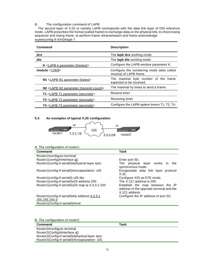
72
B. The configuration command of LAPB The second layer of X.25 or namely LAPB corresponds with the data link layer of OSI reference
mode. LAPB prescribes the format (called frame) to exchange data on the physical link, to check losing sequence and losing frame, to perform frame retransmission and frame acknowledge router(config-if-XXX)#lapb ?
Command Description
dce The lapb dce working mode
dte The lapb dte working mode
K <LAPB k parameter (frames)> Configure the LAPB window parameter K.
modulo <128/8> Configure the numbering mode (also called moulus) of LAPB frame.
N1 <LAPB N1 parameter (bytes)> The maximal byte number of the frame expected to be received.
N2 <LAPB N2 parameter (transmit count)> The maximal try times to send a frame.
T1 <LAPB T1 parameter (seconds)> Resend timer
T2 <LAPB T2 parameter (seconds)> Receiving timer
T4 <LAPB T4 parameter (seconds)> Configure the LAPB system timers T1, T2, T4.
5.3 An examples of typical X.25 configuration
;��
URXWHU�
V� V�
URXWHU����������
���������
A. The configuration of router1:
Command Task Router1#configure terminal Router1(config)#interface s0 Enter port S0. Router1(config-if-serial0)#physical-layer sync The physical layer works in the
synchronous mode. Router1(config-if-serial0)#encapsulation x25 Encapsulate data link layer protocol
X.25. Router1(config-if-serial0) x25 dte Configure X25 as DTE mode. Router1(config-if-serial0)x25 address 200 The X.121 address is 200 Router1(config-if-serial0)x25 map ip 3.3.3.2 100 Establish the map between the IP
address of the opposite terminal and the X.121 address.
Router1(config-if-serial0)#ip address 3.3.3.1 255.255.255.0
Configure the IP address of port S0.
Router1(Config-if-serial0)#end
B. The configuration of router2: Command Task Router2#configure terminal Router2(Config)#interface s0 Router2(Config-if-serial0)#physical-layer sync Router2(Config-if-serial0)#encapsulation x25
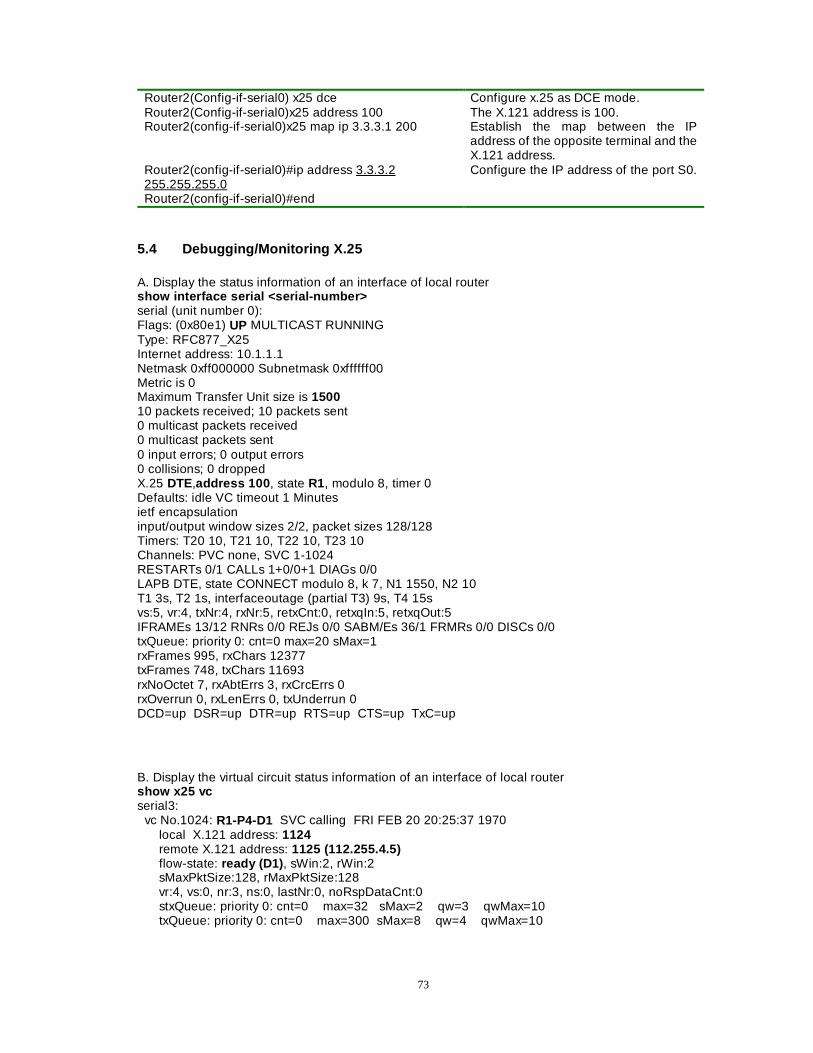
73
Router2(Config-if-serial0) x25 dce Configure x.25 as DCE mode. Router2(Config-if-serial0)x25 address 100 The X.121 address is 100. Router2(config-if-serial0)x25 map ip 3.3.3.1 200 Establish the map between the IP
address of the opposite terminal and the X.121 address.
Router2(config-if-serial0)#ip address 3.3.3.2 255.255.255.0
Configure the IP address of the port S0.
Router2(config-if-serial0)#end
5.4 Debugging/Monitoring X.25
A. Display the status information of an interface of local router show interface serial <serial-number> serial (unit number 0): Flags: (0x80e1) UP MULTICAST RUNNING Type: RFC877_X25 Internet address: 10.1.1.1 Netmask 0xff000000 Subnetmask 0xffffff00 Metric is 0 Maximum Transfer Unit size is 1500 10 packets received; 10 packets sent 0 multicast packets received 0 multicast packets sent 0 input errors; 0 output errors 0 collisions; 0 dropped X.25 DTE,address 100 , state R1, modulo 8, timer 0 Defaults: idle VC timeout 1 Minutes ietf encapsulation input/output window sizes 2/2, packet sizes 128/128 Timers: T20 10, T21 10, T22 10, T23 10 Channels: PVC none, SVC 1-1024 RESTARTs 0/1 CALLs 1+0/0+1 DIAGs 0/0 LAPB DTE, state CONNECT modulo 8, k 7, N1 1550, N2 10 T1 3s, T2 1s, interfaceoutage (partial T3) 9s, T4 15s vs:5, vr:4, txNr:4, rxNr:5, retxCnt:0, retxqIn:5, retxqOut:5 IFRAMEs 13/12 RNRs 0/0 REJs 0/0 SABM/Es 36/1 FRMRs 0/0 DISCs 0/0 txQueue: priority 0: cnt=0 max=20 sMax=1 rxFrames 995, rxChars 12377 txFrames 748, txChars 11693 rxNoOctet 7, rxAbtErrs 3, rxCrcErrs 0 rxOverrun 0, rxLenErrs 0, txUnderrun 0 DCD=up DSR=up DTR=up RTS=up CTS=up TxC=up
B. Display the virtual circuit status information of an interface of local router show x25 vc serial3: vc No.1024: R1-P4-D1 SVC calling FRI FEB 20 20:25:37 1970 local X.121 address: 1124 remote X.121 address: 1125 (112.255.4.5) flow-state: ready (D1) , sWin:2, rWin:2 sMaxPktSize:128, rMaxPktSize:128 vr:4, vs:0, nr:3, ns:0, lastNr:0, noRspDataCnt:0 stxQueue: priority 0: cnt=0 max=32 sMax=2 qw=3 qwMax=10 txQueue: priority 0: cnt=0 max=300 sMax=8 qw=4 qwMax=10
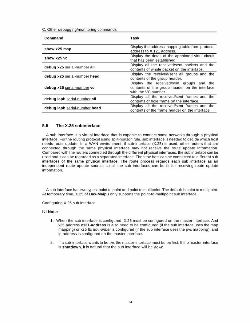
74
C. Other debugging/monitoring commands
Command Task
show x25 map Display the address mapping table from protocol address to X.121 address.
show x25 vc Display the detail of the appointed virtul circuit that has been established.
debug x25 serial-number all Display all the received/sent packets and the contents of whole packet on the interface.
debug x25 serial-number head Display the received/sent all groups and the contents of the group header.
debug x25 serial-number vc Display the received/sent groups and the contents of the group header on the interface with the VC number
debug lapb serial-number all Display all the received/sent frames and the contents of hole frame on the interface.
debug lapb serial-number head Display all the received/sent frames and the contents of the frame header on the interface
5.5 The X.25 subinterface
A sub interface is a virtual interface that is capable to connect some networks through a physical interface. For the routing protocol using split-horizon rule, sub interface is needed to decide which host needs route update. In a WAN environment, if sub-interface (X.25) is used, other routers that are connected through the same physical interface may not receive the route update information. Compared with the routers connected through the different physical interfaces, the sub interface can be used and it can be regarded as a separated interface. Then the host can be connected to different sub interfaces of the same physical interface. The route process regards each sub interface as an independent route update source; so all the sub interfaces can be fit for receiving route update information.
A sub interface has two types: point to point and point to multipoint. The default is point to multipoint. At temporary time, X.25 of Dax-Maipu only supports the point-to-multipoint sub interface. Configuring X.25 sub interface Note:
1. When the sub interface is configured, X.25 must be configured on the master-interface. And
x25 address x121-address is also need to be configured (if the sub interface uses the map mapping) or x25 ltc ltc-nunber is configured (if the sub interface uses the pvc mapping), and ip-address is configured on the master interface.
2. If a sub-interface wants to be up, the master-interface must be up first. If the master-interface
is shutdown , it is natural that the sub interface will be down.
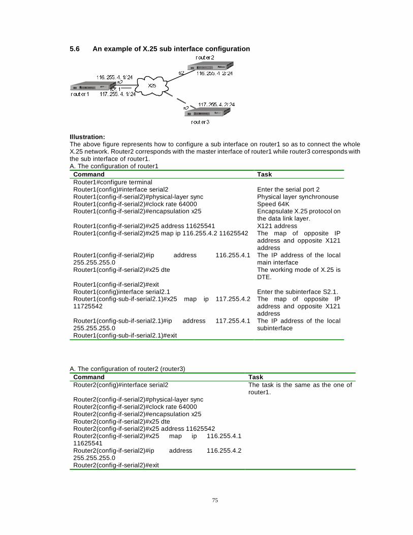
75
5.6 An example of X.25 sub interface configuration
;��
U RXW HU �
U RXW HU �
U RXW HU �
���� ���� �� �� ��
���� ���� �� �� ��
���� ���� �� �� ��
���� ���� �� �� ��
V�
V�� �
V�
V�
Illustration: The above figure represents how to configure a sub interface on router1 so as to connect the whole X.25 network. Router2 corresponds with the master interface of router1 while router3 corresponds with the sub interface of router1. A. The configuration of router1
Command Task Router1#configure terminal Router1(config)#interface serial2 Enter the serial port 2 Router1(config-if-serial2)#physical-layer sync Physical layer synchronouse Router1(config-if-serial2)#clock rate 64000 Speed 64K Router1(config-if-serial2)#encapsulation x25 Encapsulate X.25 protocol on
the data link layer. Router1(config-if-serial2)#x25 address 11625541 X121 address Router1(config-if-serial2)#x25 map ip 116.255.4.2 11625542 The map of opposite IP
address and opposite X121 address
Router1(config-if-serial2)#ip address 116.255.4.1 255.255.255.0
The IP address of the local main interface
Router1(config-if-serial2)#x25 dte The working mode of X.25 is DTE.
Router1(config-if-serial2)#exit Router1(config)interface serial2.1 Enter the subinterface S2.1. Router1(config-sub-if-serial2.1)#x25 map ip 117.255.4.2 11725542
The map of opposite IP address and opposite X121 address
Router1(config-sub-if-serial2.1)#ip address 117.255.4.1 255.255.255.0 Router1(config-sub-if-serial2.1)#exit
The IP address of the local subinterface
A. The configuration of router2 (router3) Command Task Router2(config)#interface serial2 The task is the same as the one of
router1. Router2(config-if-serial2)#physical-layer sync Router2(config-if-serial2)#clock rate 64000 Router2(config-if-serial2)#encapsulation x25 Router2(config-if-serial2)#x25 dte Router2(config-if-serial2)#x25 address 11625542 Router2(config-if-serial2)#x25 map ip 116.255.4.1 11625541
Router2(config-if-serial2)#ip address 116.255.4.2 255.255.255.0
Router2(config-if-serial2)#exit
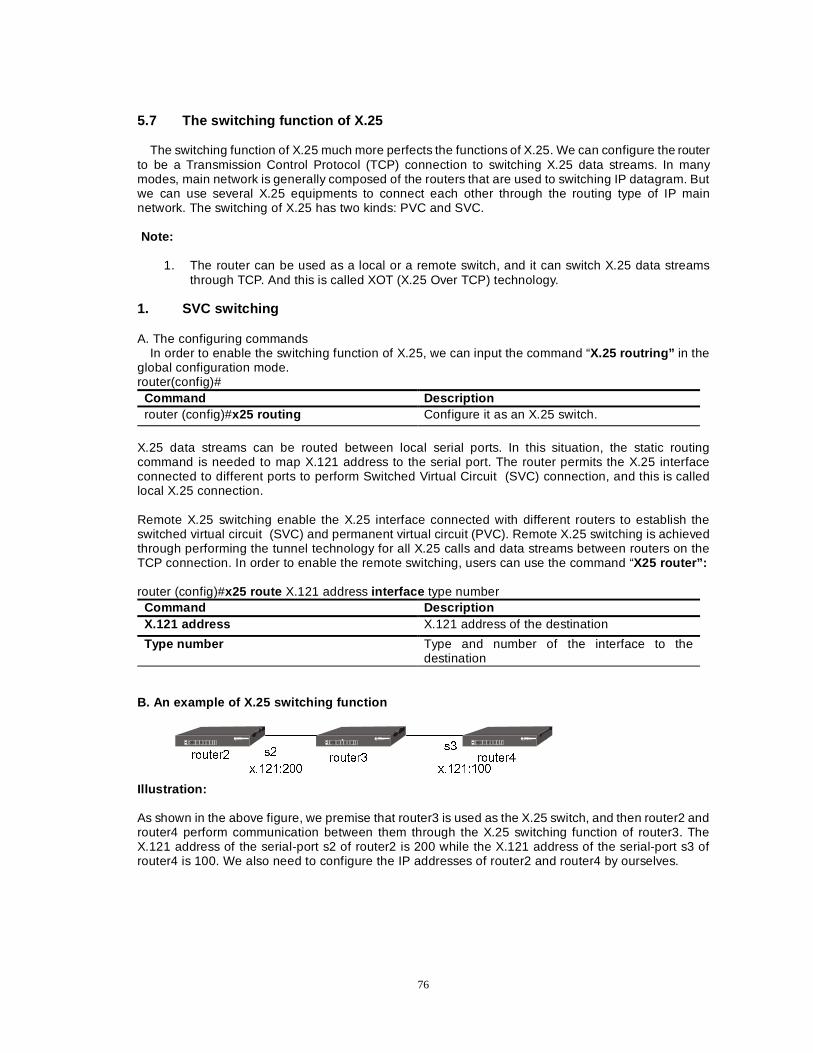
76
5.7 The switching function of X.25
The switching function of X.25 much more perfects the functions of X.25. We can configure the router to be a Transmission Control Protocol (TCP) connection to switching X.25 data streams. In many modes, main network is generally composed of the routers that are used to switching IP datagram. But we can use several X.25 equipments to connect each other through the routing type of IP main network. The switching of X.25 has two kinds: PVC and SVC. Note:
1. The router can be used as a local or a remote switch, and it can switch X.25 data streams
through TCP. And this is called XOT (X.25 Over TCP) technology. 1. SVC switching A. The configuring commands
In order to enable the switching function of X.25, we can input the command “X.25 routring” in the global configuration mode. router(config)#
Command Description router (config)#x25 routing Configure it as an X.25 switch.
X.25 data streams can be routed between local serial ports. In this situation, the static routing command is needed to map X.121 address to the serial port. The router permits the X.25 interface connected to different ports to perform Switched Virtual Circuit (SVC) connection, and this is called local X.25 connection. Remote X.25 switching enable the X.25 interface connected with different routers to establish the switched virtual circuit (SVC) and permanent virtual circuit (PVC). Remote X.25 switching is achieved through performing the tunnel technology for all X.25 calls and data streams between routers on the TCP connection. In order to enable the remote switching, users can use the command “X25 router”: router (config)#x25 route X.121 address interface type number
Command Description X.121 address X.121 address of the destination
Type number Type and number of the interface to the destination
B. An example of X.25 switching function
URXWHU� URXWHU� URXWHU�
[�������� [��������
V�V�
Illustration:
As shown in the above figure, we premise that router3 is used as the X.25 switch, and then router2 and router4 perform communication between them through the X.25 switching function of router3. The X.121 address of the serial-port s2 of router2 is 200 while the X.121 address of the serial-port s3 of router4 is 100. We also need to configure the IP addresses of router2 and router4 by ourselves.
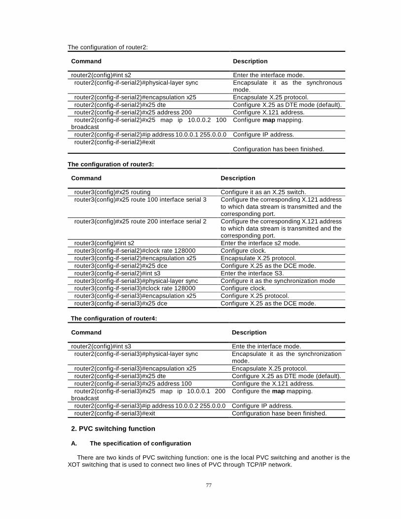
77
The configuration of router2:
Command Description
router2(config)#int s2 Enter the interface mode. router2(config-if-serial2)#physical-layer sync Encapsulate it as the synchronous
mode. router2(config-if-serial2)#encapsulation x25 Encapsulate X.25 protocol. router2(config-if-serial2)#x25 dte Configure X.25 as DTE mode (default). router2(config-if-serial2)#x25 address 200 Configure X.121 address. router2(config-if-serial2)#x25 map ip 10.0.0.2 100
broadcast Configure map mapping.
router2(config-if-serial2)#ip address 10.0.0.1 255.0.0.0 Configure IP address. router2(config-if-serial2)#exit
Configuration has been finished. The configuration of router3:
Command Description
router3(config)#x25 routing Configure it as an X.25 switch. router3(config)#x25 route 100 interface serial 3 Configure the corresponding X.121 address
to which data stream is transmitted and the corresponding port.
router3(config)#x25 route 200 interface serial 2 Configure the corresponding X.121 address to which data stream is transmitted and the corresponding port.
router3(config)#int s2 Enter the interface s2 mode. router3(config-if-serial2)#clock rate 128000 Configure clock. router3(config-if-serial2)#encapsulation x25 Encapsulate X.25 protocol. router3(config-if-serial2)#x25 dce Configure X.25 as the DCE mode. router3(config-if-serial2)#int s3 Enter the interface S3. router3(config-if-serial3)#physical-layer sync Configure it as the synchronization mode router3(config-if-serial3)#clock rate 128000 Configure clock. router3(config-if-serial3)#encapsulation x25 Configure X.25 protocol. router3(config-if-serial3)#x25 dce Configure X.25 as the DCE mode.
The configuration of router4:
Command Description
router2(config)#int s3 Ente the interface mode. router2(config-if-serial3)#physical-layer sync Encapsulate it as the synchronization
mode. router2(config-if-serial3)#encapsulation x25 Encapsulate X.25 protocol. router2(config-if-serial3)#x25 dte Configure X.25 as DTE mode (default). router2(config-if-serial3)#x25 address 100 Configure the X.121 address. router2(config-if-serial3)#x25 map ip 10.0.0.1 200
broadcast Configure the map mapping.
router2(config-if-serial3)#ip address 10.0.0.2 255.0.0.0 Configure IP address. router2(config-if-serial3)#exit Configuration hase been finished.
2. PVC switching function A. The specification of configuration
There are two kinds of PVC switching function: one is the local PVC switching and another is the XOT switching that is used to connect two lines of PVC through TCP/IP network.
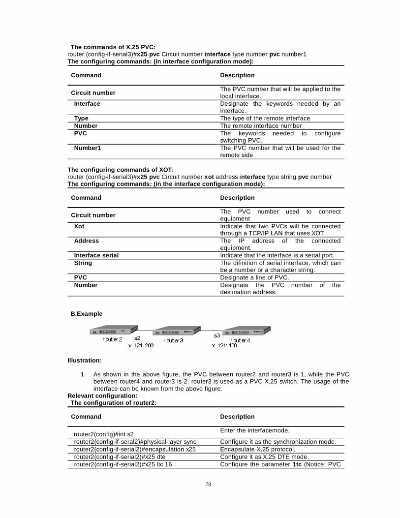
78
The commands of X.25 PVC: router (config-if-serial3)#x25 pvc Circuit number interface type number pvc number1 The configuring commands: (in interface configuration mode):
Command Description
Circuit number The PVC number that will be applied to the local interface.
Interface Designate the keywords needed by an interface.
Type The type of the remote interface Number The remote interface number PVC The keywords needed to configure
switching PVC. Number1 The PVC number that will be used for the
remote side The configuring commands of XOT: router (config-if-serial3)#x25 pvc Circuit number xot address interface type string pvc number The configuring commands: (in the interface configuration mode):
Command Description
Circuit number The PVC number used to connect equipment
Xot Indicate that two PVCs will be connected through a TCP/IP LAN that uses XOT.
Address The IP address of the connected equipment.
Interface serial Indicate that the interface is a serial port. String The difinition of serial interface, which can
be a number or a character string. PVC Designate a line of PVC. Number Designate the PVC number of the
destination address. B.Example
U RXW HU� U RXW HU� U RXW HU�
[� ���� ��� [� ���� ���
V�V�
Illustration:
1. As shown in the above figure, the PVC between router2 and router3 is 1, while the PVC
between router4 and router3 is 2. router3 is used as a PVC X.25 switch. The usage of the interface can be known from the above figure.
Relevant configuration: The configuration of router2:
Command Description
router2(config)#int s2 Enter the interfacemode.
router2(config-if-seral2)#physical-layer sync Configure it as the synchronization mode. router2(config-if-serial2)#encapsulation x25 Encapsulate X.25 protocol. router2(config-if-serial2)#x25 dte Configure it as X.25 DTE mode. router2(config-if-serial2)#x25 ltc 16 Configure the parameter 1tc (Notice: PVC
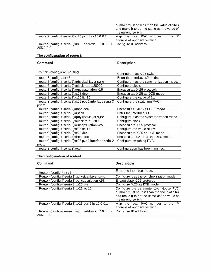
79
number must be less than the value of 1tc. ) and make it to be the same as the value of the up-end switch.
router2(config-if-serial2)#x25 pvc 1 ip 10.0.0.2 Map the local PVC number to the IP address of opposite terminal.
router2(config-if-serial2)#ip address 10.0.0.1 255.0.0.0
Configure IP address.
The configuration of router3:
Command Description
router3(config)#x25 routing Configure it as X.25 switch.
router3(config)#int s2 Enter the interface s2 mode. router3(config-if-serial2)#physical-layer sync Configure it as the synchronization mode. router3(config-if-serial2)#clock rate 128000 Configure clock. router3(config-if-serial2)#encapsulation x25 Encapsulate X.25 protocol. router3(config-if-serial2)#x25 dce Encapsulate X.25 as DCE mode. router3(config-if-serial2)#x25 ltc 16 Configure the value of 1tc. router3(config-if-serial2)#x25 pvc 1 interface serial 3
pvc 2 Configure the switching PVC.
router3(config-if-serial2)#lapb dce Encapsulae LAPB as DEC mode. router3(config-if-serial2)#int s3 Enter the interface s3. router3(config-if-serial3)#physical-layer sync Configure it as the synchronization mode. router3(config-if-serial3)#clock rate 128000 Configure clock. router3(config-if-serial3)#encapsulation x25 Encapsulate X.25 protocol. router3(config-if-serial3)#x25 ltc 16 Configure the value of 1tc. router3(config-if-serial3)#x25 dce Encapsulate X.25 as DCE mode. router3(config-if-serial3)#lapb dce Encapsulate LAPB as the DEC mode. router3(config-if-serial3)#x25 pvc 2 interface serial 2
pvc 1 Configure switching PVC.
router3(config-if-serial3)#exit Configuration has been finished. The configuration of router4:
Command Description
Router4(config)#int s3 Enter the interface mode.
Router4(config-if-serial3)#physical-layer sync Configure it as the synchronization mode. Router4(config-if-serial3)#encapsulation x25 Encapsulate X.25 protocol. Router4(config-if-serial3)#x25 dte Configure X.25 as DTE mode. Router4(config-if-serial3)#x25 ltc 16 Configure the parameter 1tc (Notice PVC
number must be less than the value of 1tc ) and make it to be the same as the value of the up-end switch.
Router4(config-if-serial3)#x25 pvc 2 ip 10.0.0.1 Map the local PVC number to the IP address of opposite terminal.
Router4(config-if-serial3)#ip address 10.0.0.2 255.0.0.0
Configure IP address.
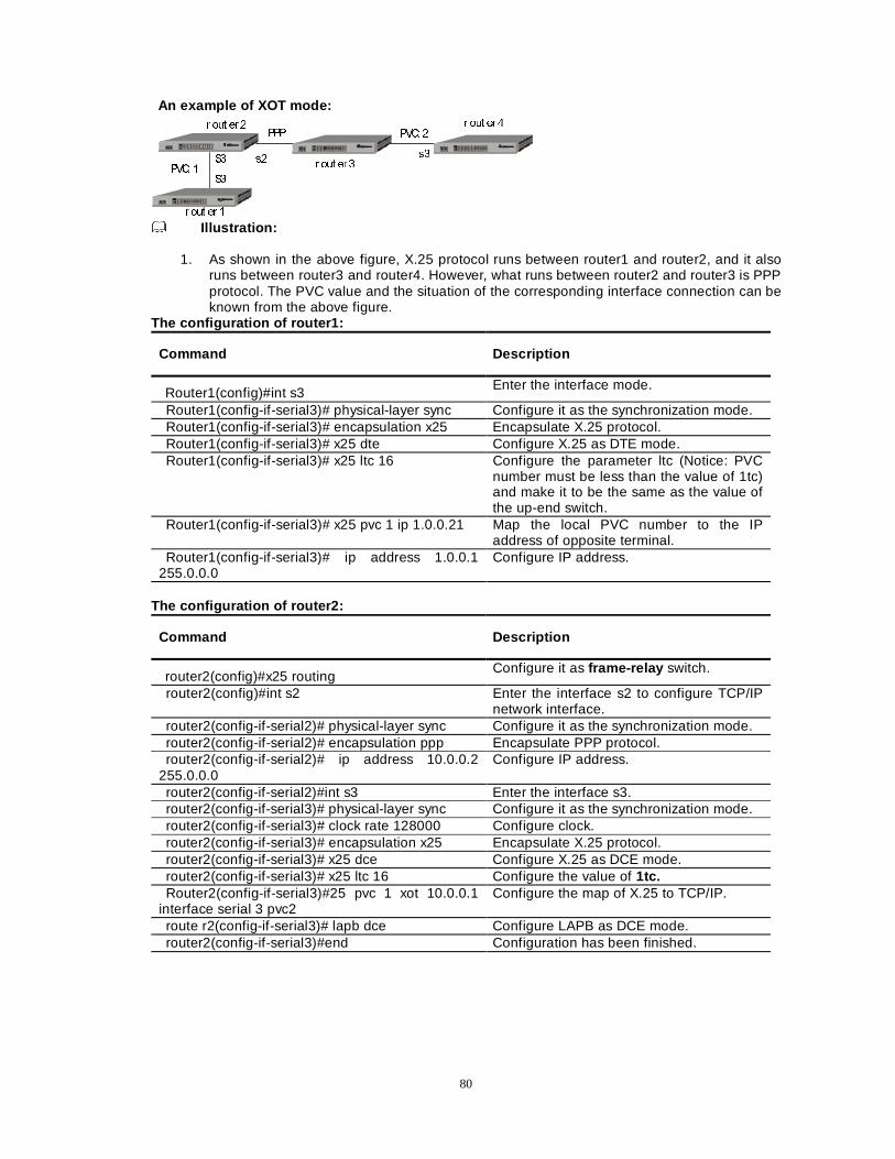
80
An example of XOT mode: U RXW HU �
U RXW HU �
U RXW HU �
V�V�
U RXW HU �
39&� �
39&� �333
6�
6�
Illustration:
1. As shown in the above figure, X.25 protocol runs between router1 and router2, and it also
runs between router3 and router4. However, what runs between router2 and router3 is PPP protocol. The PVC value and the situation of the corresponding interface connection can be known from the above figure.
The configuration of router1:
Command Description
Router1(config)#int s3 Enter the interface mode.
Router1(config-if-serial3)# physical-layer sync Configure it as the synchronization mode. Router1(config-if-serial3)# encapsulation x25 Encapsulate X.25 protocol. Router1(config-if-serial3)# x25 dte Configure X.25 as DTE mode. Router1(config-if-serial3)# x25 ltc 16 Configure the parameter ltc (Notice: PVC
number must be less than the value of 1tc) and make it to be the same as the value of the up-end switch.
Router1(config-if-serial3)# x25 pvc 1 ip 1.0.0.21 Map the local PVC number to the IP address of opposite terminal.
Router1(config-if-serial3)# ip address 1.0.0.1 255.0.0.0
Configure IP address.
The configuration of router2:
Command Description
router2(config)#x25 routing Configure it as frame-relay switch.
router2(config)#int s2 Enter the interface s2 to configure TCP/IP network interface.
router2(config-if-serial2)# physical-layer sync Configure it as the synchronization mode. router2(config-if-serial2)# encapsulation ppp Encapsulate PPP protocol. router2(config-if-serial2)# ip address 10.0.0.2
255.0.0.0 Configure IP address.
router2(config-if-serial2)#int s3 Enter the interface s3. router2(config-if-serial3)# physical-layer sync Configure it as the synchronization mode. router2(config-if-serial3)# clock rate 128000 Configure clock. router2(config-if-serial3)# encapsulation x25 Encapsulate X.25 protocol. router2(config-if-serial3)# x25 dce Configure X.25 as DCE mode. router2(config-if-serial3)# x25 ltc 16 Configure the value of 1tc. Router2(config-if-serial3)#25 pvc 1 xot 10.0.0.1
interface serial 3 pvc2 Configure the map of X.25 to TCP/IP.
route r2(config-if-serial3)# lapb dce Configure LAPB as DCE mode. router2(config-if-serial3)#end Configuration has been finished.
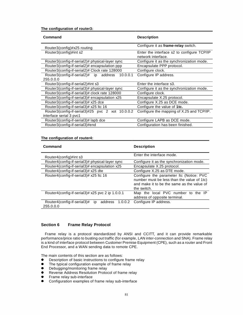
81
The configuration of router3:
Command Description
Router3(config)#x25 routing Configure it as frame-relay switch.
Router3(config)#int s2 Enter the interface s2 to configure TCP/IP network interface.
Router3(config-if-serial2)# physical-layer sync Configure it as the synchronization mode. Router3(config-if-serial2)# encapsulation ppp Encapsulate PPP protocol. Router3(config-if-serial2)# Clock rate 128000 Configure clock. Router3(config-if-serial2)# ip address 10.0.0.1
255.0.0.0 Configure IP address.
Router3(config-if-serial2)#int s3 Enter the interface s3. Router3(config-if-serial3)# physical-layer sync Configure it as the synchronization mode. Router3(config-if-serial3)# clock rate 128000 Configure clock. Router3(config-if-serial3)# encapsulation x25 Encapsulate X.25 protocol. Router3(config-if-serial3)# x25 dce Configure X.25 as DCE mode. Router3(config-if-serial3)# x25 ltc 16 Configure the value of 1tc. Router3(config-if-serial3)#25 pvc 2 xot 10.0.0.2
interface serial 3 pvc1 Configure the mapping of X.25 and TCP/IP.
Router3(config-if-serial3)# lapb dce Configure LAPB as DCE mode. Router3(config-if-serial3)#end Configuration has been finished.
The configuration of router4:
Command Description
Router4(config)#int s3 Enter the interface mode.
Router4(config-if-serial3)# physical-layer sync Configure it as the synchronization mode. Router4(config-if-serial3)# encapsulation x25 Encapsulate X.25 protocol. Router4(config-if-serial3)# x25 dte Configure X.25 as DTE mode. Router4(config-if-serial3)# x25 ltc 16 Configure the parameter ltc (Notice: PVC
number must be less than the value of 1tc) and make it to be the same as the value of the switch.
Router4(config-if-serial3)# x25 pvc 2 ip 1.0.0.1 Map the local PVC number to the IP address of opposite terminal.
Router4(config-if-serial3)# ip address 1.0.0.2 255.0.0.0
Configure IP address.
Section 6 Frame Relay Protocol
Frame relay is a protocol standardized by ANSI and CCITT, and it can provide remarkable performance/price ratio to busting out traffic (for example, LAN inter-connection and SNA). Frame relay is a kind of interface protocol between Customer Premise Equipment (CPE), such as a router and Front End Processor, and a WAN sending data to remote CPE. The main contents of this section are as follows: z Description of basic instructions to configure frame relay z The typical configuration example of frame relay z Debugging/monitoring frame relay z Reverse Address Resolution Protocol of frame relay z Frame relay sub-interface z Configuration examples of frame relay sub-interface
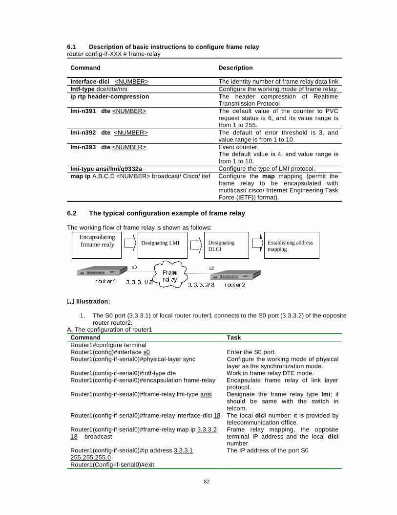
82
6.1 Description of basic instructions to configure frame relay router config-if-XXX # frame-relay
Command Description
Interface-dlci <NUMBER> The identity number of frame relay data link Intf-type dce/dte/nni Configure the working mode of frame relay. ip rtp header-compression The header compression of Realtime
Transmission Protocol lmi-n391 dte <NUMBER> The default value of the counter to PVC
request status is 6, and its value range is from 1 to 255.
lmi-n392 dte <NUMBER> The default of error threshold is 3, and value range is from 1 to 10.
lmi-n393 dte <NUMBER> Event counter. The default value is 4, and value range is from 1 to 10.
lmi-type ansi /lmi /q9332a Configure the type of LMI protocol. map ip A.B.C.D <NUMBER> broadcast/ Cisco/ itef Configure the map mapping (permit the
frame relay to be encapsulated with mutlticast/ cisco/ Internet Engineering Task Force (IETF)) format).
6.2 The typical configuration example of frame relay The working flow of frame relay is shown as follows:
)U DPH
U HO D\U RXW HU �
V� V�
U RXW HU ��� �� �� �� �
�� �� �� �� �
Illustration:
1. The S0 port (3.3.3.1) of local router router1 connects to the S0 port (3.3.3.2) of the opposite
router router2. A. The configuration of router1
Command Task Router1#configure terminal Router1(config)#interface s0 Enter the S0 port. Router1(config-if-serial0)#physical-layer sync Configure the working mode of physical
layer as the synchronization mode. Router1(config-if-serial0)#intf-type dte Work in frame relay DTE mode. Router1(config-if-serial0)#encapsulation frame-relay Encapsulate frame relay of link layer
protocol. Router1(config-if-serial0)#frame-relay lmi-type ansi Designate the frame relay type lmi : it
should be same with the switch in telcom.
Router1(config-if-serial0)#frame-relay interface-dlci 18 The local dlci number: it is provided by telecommunication office.
Router1(config-if-serial0)#frame-relay map ip 3.3.3.2 18 broadcast
Frame relay mapping, the opposite terminal IP address and the local dlci number
Router1(config-if-serial0)#ip address 3.3.3.1 255.255.255.0
The IP address of the port S0
Router1(Config-if-serial0)#exit
Encapsulating frmame realy
Designating LMI
Designating DLCI
Establishing address mapping
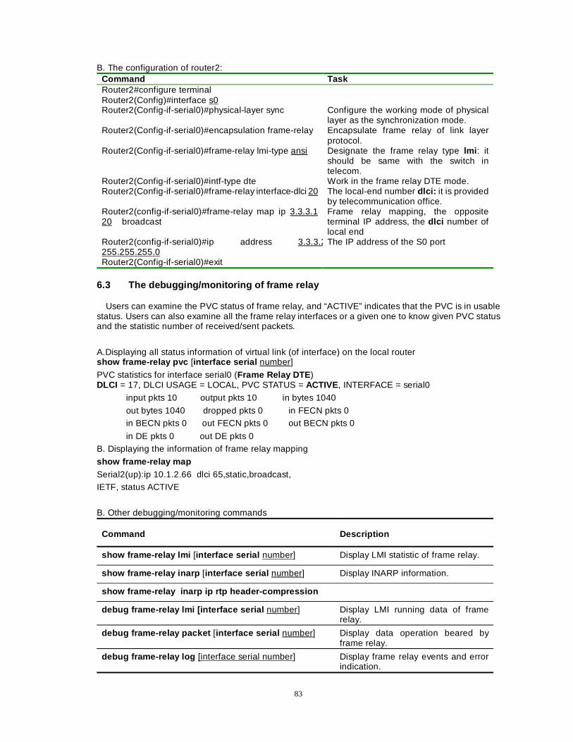
83
B. The configuration of router2: Command Task Router2#configure terminal Router2(Config)#interface s0 Router2(Config-if-serial0)#physical-layer sync Configure the working mode of physical
layer as the synchronization mode. Router2(Config-if-serial0)#encapsulation frame-relay Encapsulate frame relay of link layer
protocol. Router2(Config-if-serial0)#frame-relay lmi-type ansi Designate the frame relay type lmi : it
should be same with the switch in telecom.
Router2(Config-if-serial0)#intf-type dte Work in the frame relay DTE mode. Router2(Config-if-serial0)#frame-relay interface-dlci 20 The local-end number dlci: it is provided
by telecommunication office. Router2(config-if-serial0)#frame-relay map ip 3.3.3.1 20 broadcast
Frame relay mapping, the opposite terminal IP address, the dlci number of local end
Router2(config-if-serial0)#ip address 3.3.3.2255.255.255.0
The IP address of the S0 port
Router2(Config-if-serial0)#exit 6.3 The debugging/monitoring of frame relay
Users can examine the PVC status of frame relay, and “ACTIVE” indicates that the PVC is in usable status. Users can also examine all the frame relay interfaces or a given one to know given PVC status and the statistic number of received/sent packets.
A.Displaying all status information of virtual link (of interface) on the local router show frame-relay pvc [interface serial number]
PVC statistics for interface serial0 (Frame Relay DTE ) DLCI = 17, DLCI USAGE = LOCAL, PVC STATUS = ACTIVE, INTERFACE = serial0
input pkts 10 output pkts 10 in bytes 1040
out bytes 1040 dropped pkts 0 in FECN pkts 0 in BECN pkts 0 out FECN pkts 0 out BECN pkts 0
in DE pkts 0 out DE pkts 0 B. Displaying the information of frame relay mapping show frame-relay map
Serial2(up):ip 10.1.2.66 dlci 65,static,broadcast, IETF, status ACTIVE
B. Other debugging/monitoring commands
Command Description
show frame-relay lmi [interface serial number] Display LMI statistic of frame relay.
show frame-relay inarp [interface serial number] Display INARP information.
show frame-relay inarp ip rtp header-compression
debug frame-relay lmi [interface serial number] Display LMI running data of frame relay.
debug frame-relay packet [interface serial number] Display data operation beared by frame relay.
debug frame-relay log [interface serial number] Display frame relay events and error indication.
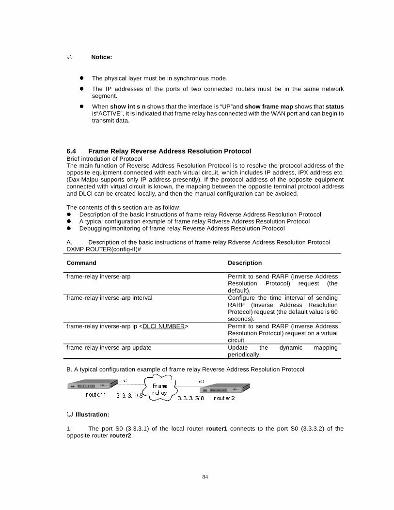
84
� Notice:
z The physical layer must be in synchronous mode.
z The IP addresses of the ports of two connected routers must be in the same network segment.
z When show int s n shows that the interface is “UP”and show frame map shows that status is“ACTIVE”, it is indicated that frame relay has connected with the WAN port and can begin to transmit data.
6.4 Frame Relay Reverse Address Resolution Protocol Brief introdution of Protocol The main function of Reverse Address Resolution Protocol is to resolve the protocol address of the opposite equipment connected with each virtual circuit, which includes IP address, IPX address etc. (Dax-Maipu supports only IP address presently). If the protocol address of the opposite equipment connected with virtual circuit is known, the mapping between the opposite terminal protocol address and DLCI can be created locally, and then the manual configuration can be avoided. The contents of this section are as follow: z Description of the basic instructions of frame relay Rdverse Address Resolution Protocol z A typical configuration example of frame relay Rdverse Address Resolution Protocol z Debugging/monitoring of frame relay Reverse Address Resolution Protocol A. Description of the basic instructions of frame relay Rdverse Address Resolution Protocol DXMP ROUTER(config-if)#
Command Description
frame-relay inverse-arp Permit to send RARP (Inverse Address Resolution Protocol) request (the default).
frame-relay inverse-arp interval Configure the time interval of sending RARP (Inverse Address Resolution Protocol) request (the default value is 60 seconds).
frame-relay inverse-arp ip <DLCI NUMBER> Permit to send RARP (Inverse Address Resolution Protocol) request on a virtual circuit.
frame-relay inverse-arp update Update the dynamic mapping periodically.
B. A typical configuration example of frame relay Reverse Address Resolution Protocol
)U DPH
U HO D\U RXW HU �
V� V�
U RXW HU ��� �� �� �� �
�� �� �� �� �
Illustration: 1. The port S0 (3.3.3.1) of the local router router1 connects to the port S0 (3.3.3.2) of the opposite router router2 .
85
The configuration of router1 Router1(config-if-serial0)# encapsulation frame-relay Router1(config-if-serial0)# frame-relay lmi-type ansi The type of LMI Router1(config-if-serial0)# frame-relay inverse-arp Permit to send frame relay RARP (the
default). Router1(config-if-serial0)#ip address 3.3.3.1 255.0.0.0 Local-end IP address. Router1(config-if-serial0)#frame-relay inverse-arp update
Update the dynamic mapping periodically.
Router1(config-if-serial0)#frame-relay interface-dlci 16 Configure DLCI number. The configuration of router2
Router2(config-if-serial0)# encapsulation frame-relay Router2(config-if-serial0)# frame-relay lmi-type ansi The type LMI. Router2(config-if)# frame-relay inverse-arp Permit to send frame relay RARP (the
default) Router2(config-if-serial0)#ip address 3.3.3.2 255.0.0.0 Local IP address. Router2(config-if-serial0)#frame-relay inverse-arp update
Update the dynamic mapping periodically.
Router2(config-if-serial0)#frame-relay interface-dlci 16 Configure DLCI number. C. Debugging/monitoring of frame relay Reverse Address Resolution Protocol (RARP) Displaying packets receiving/sending status of frame relay Rdverse Address Resolution Protocol show frame-relay inarp
Frame Relay Inarp statistics for interface serial2: InARP requests sent 5, InARP replies sent 0 InARP request recvd 0, InARP replies recvd 4
Displaying the information of frame relay mapping show frame-relay map
serial0 (up): ip 3.3.3.2, dlci 16, dynamic , IETF, status ACTIVE Note: 1. The word dynamic among the above information indicates that the mapping is established
dynamically through the Reverse Address Resolution Protocol (RARP).
6.5 Frame relay sub-interface The configuration process of a frame relay sub-interface:
A subinterface inherits the properties of a masterinterface, so before the subinterface is configured, the frame relay must be encapsulated on the main interface. [LMI] A. The configuration of frame relay point-to-point interface DXMP ROUTER(config)#
Command Description
interface Serial <serialnumber.subnumber> point-to-point Configure the subinterface as the point-to-point mode.
frame-relay interface-dlci number Configure the number of the data link connection identifier (DLCI).
Frame relay is encapsulated on
the masterinterface.
Designate the type of sub-interface: Point-to-
Point/Point-to-multipoint.
Frame relay is configured on the subinterface. configures
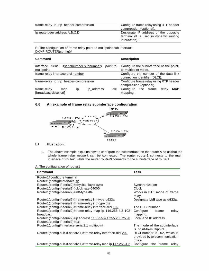
86
frame-relay ip rtp header-compression Configure frame relay using RTP header compression (optional).
Ip route peer-address A.B.C.D Designate IP address of the opposite terminal (It is used in dynamic routing interaction).
B. The configurition of frame relay point-to-multipoint sub-interface DXMP ROUTER(config)#
Command Description
interface Serial <serialnumber.subnumber> point-to-multipoint
Configure the subinterface as the point-to-multipoint mode.
frame-relay interface-dlci number Configure the number of the data link connection identifier (DLCI).
frame-relay ip rtp header-compression Configure frame relay using RTP header compression (optional).
frame-relay map ip ip_address dlci [broadcast|cisco|ietf]
Configure the frame relay MAP mapping.
6.6 An example of frame relay subinterface configuration
U RXW HU �
U RXW HU �
U RXW HU �
���� ���� �� �� ��
���� ���� �� �� ��
���� ���� �� �� ��
���� ���� �� �� ��
V�
V�� �
V�
V�
)U DPH U HO D\
Illustration:
1. The above example explains how to configure the subinterface on the router A so as that the
whole frame relay network can be connected. The router router2 connects to the main interface of router1 while the router router3 connects to the subinterface of router1.
A. The configuration of router1
Command Task
Router1#configure terminal Router1(config)#interface s2 Router1(config-if-serial2)#physical-layer sync Synchronization Router1(config-if-serial2)#clock rate 64000 Clock Router1(config-if-serial2)#intf-type dte Works in DTE mode of frame
relay. Router1(config-if-serial2)#frame-relay lmi-type q933a Designate LMI type as q933a. Router1(config-if-serial2)#frame-relay intf-type dte Router1(config-if-serial2)#frame-relay interface-dlci 102 The DLCI number Router1(config-if-serial2)#frame-relay map ip 116.255.4.2 102 broadcast
Configure frame relay mapping.
Router1(config-if-serial2)#ip address 116.255.4.1 255.255.255.0 Local-end IP address Router1(config-if-serial2)#exit Router1(config)#interface serial2.1 multipoint The mode of the subinterface
is point-to-multipoint. Router1(config-sub-if-serial2.1)#frame-relay interface-dlci 202 DLCI number is 202, which is
provided by telecommunication office.
Router1(config-sub-if-serial2.1)#frame-relay map ip 117.255.4.2 Configure the frame relay
87
202 broadcast mapping of the subinterface. Router1(config-sub-if-serial2.1)#ip address 117.255.4.1 255.255.255.0
IP address of the subinterface.
Router1(config-sub-if)#end
B. The configuration of router2 (router3) Command Task Router2# con t Router2(config )#interface serial2
Router2(config-if-serial2)#physical-layer sync Router2(config-if-serial2)#clock rate 64000 Router2(config-if-serial2)#encapsulation frame-relay Encapsulate frame relay. Router2(config-if-serial2)#frame-relay lmi-type q933a Designate LMI type as q933a. Router2(config-if-serial2)#frame-relay interface-dlci 101 The DLCI number is 101. Router2(config-if-serial2)#frame-relay map ip 116.255.4.1 101 broadcast
Configure the frame relay mapping.
Router2(config-if-serial2)#ip address 116.255.4.2 255.255.255.0
IP address
Router2(config-if-serial2)#exit
6.7 Frame Relay Switch 1. Brief introdution of commands Dax-Maipu supports the function of frame relay switch. Frame relay switch makes the router be able to encapsulate the data frame of frame relay into IP datagram router(config)#frame-relay switching A. Configuring it as a frame relay switch router(config)#
Command Task
Frame-relay switching Configure it as a frame relay switch.
Configure the router, through the command frame-relay switching, to execute the switch function in frame relay network. When the router runs as a Router(config)#frame-relay switching switch, data stream can be exchanged between two serial ports of the router through the command frame-relay . The router executes PVC data exchange between two serial ports.
router(config-if-XXX)#frame-relay route in-dlci out-interface out-dlci B. The command frame-relay switching Router(config-if-XXX)#
Command Task
In-dlci The DLCI number of packets received by the interface
Out-interface The interface used by the router to transmit packets
Out-dlci The DLCI number used by the router to transmit packets through the designated outward interface
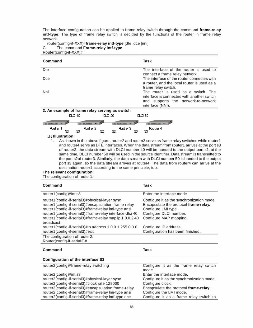
88
The interface configuration can be applied to frame relay switch through the command frame-relay intf-type . The type of frame relay switch is decided by the functions of the router in frame relay network. router(config-if-XXX)#frame-relay intf-type [dte |dce |nni] C. The command Frame-relay intf-type Router(config-if-XXX)#
Command Task
Dte The interface of the router is used to connect a frame relay network.
Dce The interface of the router connectes with a router, and the local router is used as a frame relay switch.
Nni The router is used as a switch. The interface is connected with another switch and supports the network-to-network interface (NNI).
2. An example of frame relay serving as switch '/&, �� '/&, �� '/&, ��
5RXW HU � 5RXW HU � 5RXW HU � 5RXW HU �6� 6� 6�6�6� 6�
Illustration: 1. As shown in the above figure, router2 and router3 serve as frame relay switches while router1
and router4 serve as DTE interfaces. When the data stream from router1 arrives at the port s3 of router2, the data stream with DLCI number 40 will be handed to the output port s2; at the same time, DLCI number 50 will be used in the source identifier. Data stream is transmitted to the port s2of router3. Similarly, the data stream with DLCI number 50 is handed to the output port s3 again, so the data stream arrives at router4. The data from router4 can arrive at the destination router1 according to the same principle, too.
The relevant configuration: The configuration of router1:
Command Task
router1(config)#int s3 Enter the interface mode.
router1(config-if-serial3)#physical-layer sync Configure it as the synchronization mode. router1(config-if-serial3)#encapsulation frame-relay Encapsulate the protocol frame-relay. router1(config-if-serial3)#frame-relay lmi-type ansi Configure LMI type. router1(config-if-serial3)#frame-relay interface-dlci 40 Configure DLCI number. router1(config-if-serial3)#frame-relay map ip 1.0.0.2 40 broadcast
Configure MAP mapping.
router1(config-if-serial3)#ip address 1.0.0.1 255.0.0.0 Configure IP address. router1(config-if-serial3)#exit Configuration has been finished. The configuration of router2: Router(config-if-serial2)#
Command Task
Configuration of the interface S3
router2(config)#frame-relay switching Configure it as the frame relay switch mode.
router2(config)#int s3 Enter the interface mode. router2(config-if-serial3)#physical-layer sync Configure it as the synchronization mode. router2(config-if-serial3)#clock rate 128000 Configure clock. router2(config-if-serial3)#encapsulation frame-relay Encapsulate the protocol frame-relay . router2(config-if-serial3)#frame-relay lmi-type ansi Configure the LMI mode. router2(config-if-serial3)#frame-relay intf-type dce Configure it as a frame relay switch to
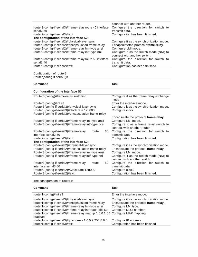
89
connect with another router. router2(config-if-serial3)#frame-relay route 40 interface serial2 50
Configure the direction for switch to transmit data.
router2(config-if-serial3)#exit Configuration has been finished. The configuration of the interface S2: router2(config-if-serial2)#physical-layer sync Configure it as the synchronization mode. router2(config-if-serial2)#encapsulation frame-relay Encapsulatethe protocol frame-relay. router2(config-if-serial2)#frame-relay lmi-type ansi Configure LMI mode. router2(config-if-serial2)#frame-relay intf-type nni Configure it as the switch mode (NNI) to
connect with another switch. router2(config-if-serial2)#frame-relay route 50 interface serial3 40
Configure the direction for switch to transmit data.
router2(config-if-serial2)#exit Configuration has been finished. Configuration of router3: Router(config-if-serial2)#
Command Task
Configuration of the interface S3
Router3(config)#frame-relay switching Configure it as the frame relay exchange mode.
Router3(config)#int s3 Enter the interface mode. Router3(config-if-serial3)#physical-layer sync Configure it as the synchronization mode. Router3(config-if-serial3)#clock rate 128000 Configure clock. Router3(config-if-serial3)#encapsulation frame-relay
Encapsulate the protocol frame-relay . Router3(config-if-serial3)#frame-relay lmi-type ansi Configure LMI mode. Router3(config-if-serial3)#frame-relay intf-type dce Configure it as a frame relay switch to
connect with another router. Router3(config-if-serial3)#frame-relay route 60 interface serial2 50
Configure the direction for switch to transmit data.
router2(config-if-serial3)#exit Configuration has been finished. The configuration of the interface S2: Router3(config-if-serial2)#physical-layer sync Configure it as the synchronization mode. Router3(config-if-serial2)#encapsulation frame-relay Encapsulate the protocol frame-relay . Router3(config-if-serial2)#frame-relay lmi-type ansi Configure LMI mode. Router3(config-if-serial2)#frame-relay intf-type nni Configure it as the switch mode (NNI) to
connect with another switch. Router3(config-if-serial2)#frame-relay route 50 interface serial3 60
Configure the direction for switch to transmit data.
Router3(config-if-serial2)#Clock rate 128000 Configure clock. Router3(config-if-serial2)#exit Configuration has been finished. The configuration of router4:
Command Task
router1(config)#int s3 Enter the interface mode.
router1(config-if-serial3)#physical-layer sync Configure it as the synchronization mode. router1(config-if-serial3)#encapsulation frame-relay Encapsulate the protocol frame-relay . router1(config-if-serial3)#frame-relay lmi-type ansi Configure LMI type. router1(config-if-serial3)#frame-relay interface-dlci 60 Configure DLCI number. router1(config-if-serial3)#frame-relay map ip 1.0.0.1 60roadcast
Configure MAP mapping.
router1(config-if-serial3)#ip address 1.0.0.2 255.0.0.0 Configure IP address. router1(config-if-serial3)#exit Configuration has been finished

90
Note: 1. The DLCI numbers between switches needn’t be configured in ports. 2. In fact, different LMI types can be configured on different ports and the same LMI type is
unnecessary. But the LMI between two routers must be the same. 3. Examine whether the function of switch works well through the command show frame-relay
route . If S2 and S3 are showed as active , this indicates that the function of switch wroks well.
91
Chapter 6 DDR and Interface Backup
This chapter mainly describes how to configure DXMP ROUTER to perform the remote dialer access through PSTN and ISDN (Integrated Services Digital Network). The main contents of this chapter are as follows: 1 Dialer backup
z Built-in frequency-band MODEM configuration z Dialer script z Interface backup z The typical case of dialer backup
2 The configuration of DDR dialer
z The DDR configuration in PSTN network z Dialer call back z ISDN configuration
3 Dialer prototype
� Dialer interface � Dialer map-class � Dialer pool � Physical interface � Examples of Configuration
Section 1 Dialer Backup 1.1 The Configuration of a Built-in Frequency-band MODEM A built-in frequency-band modem of Dax-Maipu supports several dialer modes, such as synchronism, asynchronism, dialer line, and leased line etc. This section mainly describes how to configure the built-in frequency-band modem of Dax-Maipu to perform the remote dialer. 1) The relevant commands A. Configuring modem parameters
router(config-if-XXX)#modem ?
Command Explanation
async-mode Configure it as the asynchronous mode, including buffer asynchronism, direct asynchronism and error asynchronism. (If you add a “?” behind the command modem async-mode , you can see the prompt of the next step. Of course, you can get help of all the configuration through using “?”)
clock-mode In the synchronous mode, internal clock, external clock and slave clock can be configured. In the asynchronous mode, it is unnecessary to configure the clock.
clock-rate In the synchronous mode, modem circuitry rate is configured. (In the asynchronous mode, the command speed is used to configure interface rate)
outer The command is used to configure an outer modem, while it isn’t used to configure a built-in modem.
party The command is used to configure modem as originator or answer.
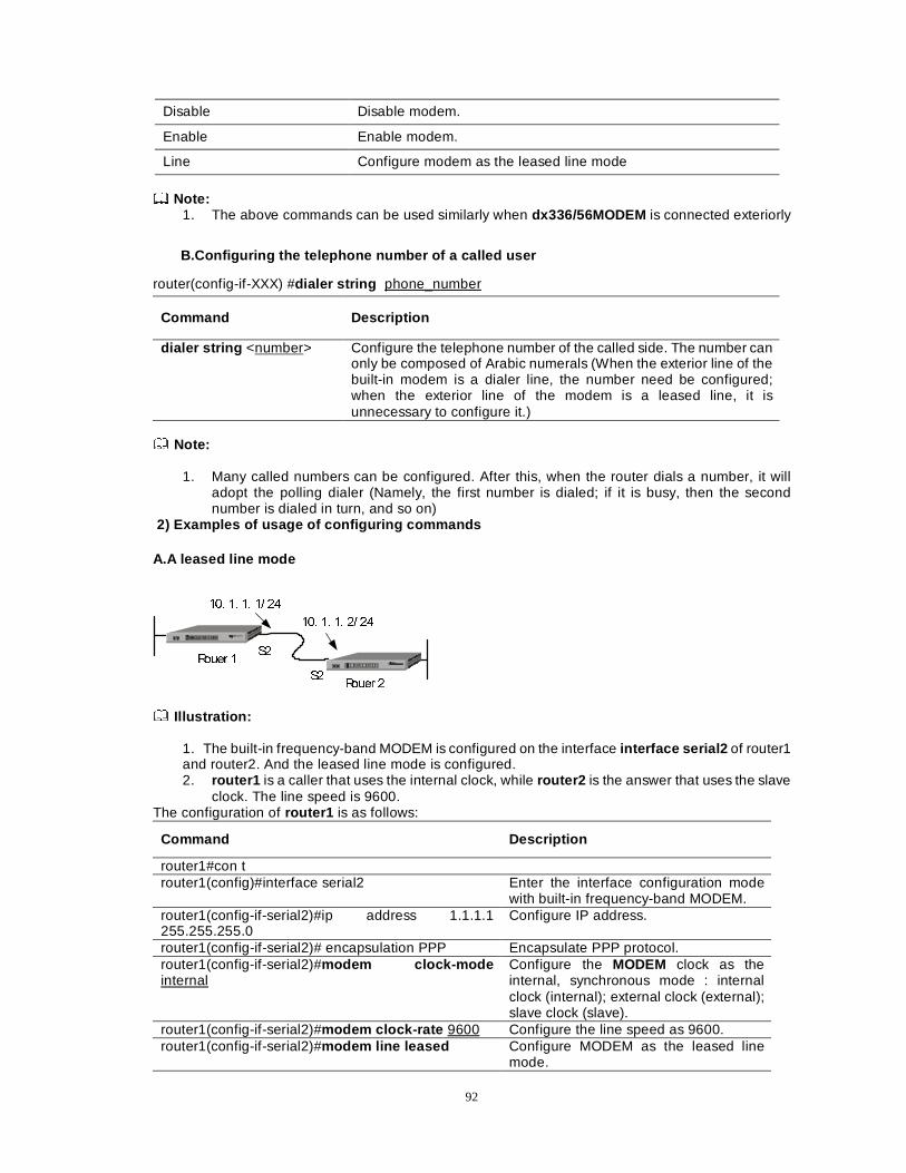
92
Disable Disable modem.
Enable Enable modem.
Line Configure modem as the leased line mode
Note:
1. The above commands can be used similarly when dx336/56MODEM is connected exteriorly
B.Configuring the telephone number of a called user
router(config-if-XXX) #dialer string phone_number
Command Description
dialer string <number> Configure the telephone number of the called side. The number can only be composed of Arabic numerals (When the exterior line of the built-in modem is a dialer line, the number need be configured; when the exterior line of the modem is a leased line, it is unnecessary to configure it.)
Note:
1. Many called numbers can be configured. After this, when the router dials a number, it will
adopt the polling dialer (Namely, the first number is dialed; if it is busy, then the second number is dialed in turn, and so on)
2) Examples of usage of configuring commands
A.A leased line mode
5RXHU �
5RXHU �
6�
6�
��� �� �� �� ��
��� �� �� �� ��
Illustration:
1. The built-in frequency-band MODEM is configured on the interface interface serial2 of router1 and router2. And the leased line mode is configured. 2. router1 is a caller that uses the internal clock, while router2 is the answer that uses the slave
clock. The line speed is 9600. The configuration of router1 is as follows:
Command Description
router1#con t router1(config)#interface serial2 Enter the interface configuration mode
with built-in frequency-band MODEM. router1(config-if-serial2)#ip address 1.1.1.1 255.255.255.0
Configure IP address.
router1(config-if-serial2)# encapsulation PPP Encapsulate PPP protocol. router1(config-if-serial2)#modem clock-mode internal
Configure the MODEM clock as the internal, synchronous mode : internal clock (internal); external clock (external); slave clock (slave).
router1(config-if-serial2)#modem clock-rate 9600 Configure the line speed as 9600. router1(config-if-serial2)#modem line leased Configure MODEM as the leased line
mode.
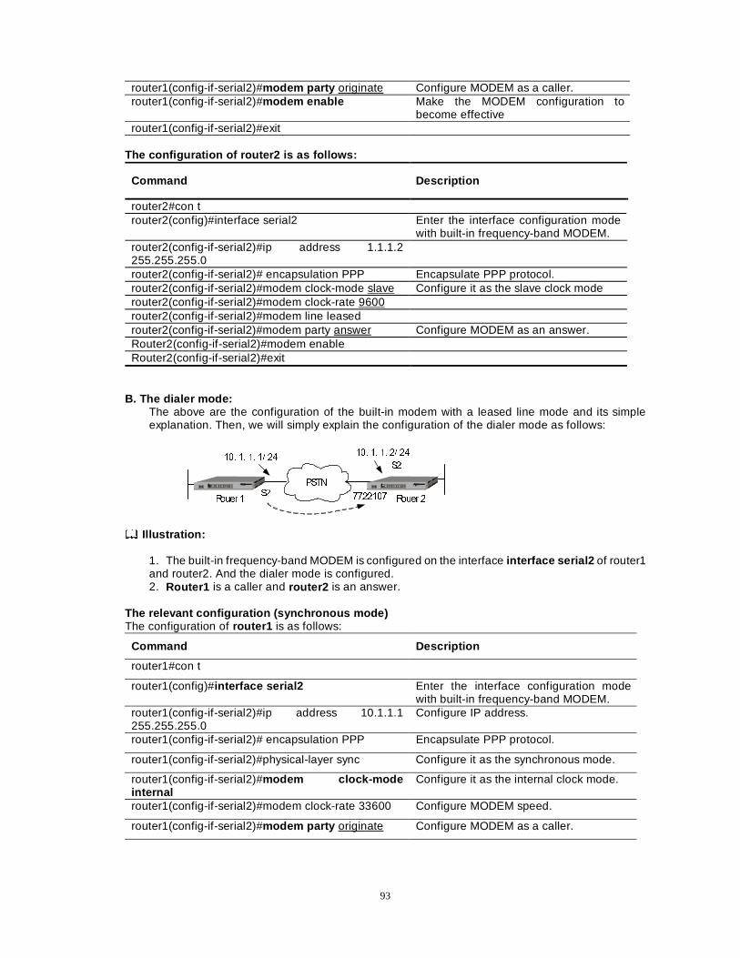
93
router1(config-if-serial2)#modem party originate Configure MODEM as a caller. router1(config-if-serial2)#modem enable Make the MODEM configuration to
become effective router1(config-if-serial2)#exit
The configuration of router2 is as follows:
Command Description
router2#con t router2(config)#interface serial2 Enter the interface configuration mode
with built-in frequency-band MODEM. router2(config-if-serial2)#ip address 1.1.1.2 255.255.255.0
router2(config-if-serial2)# encapsulation PPP Encapsulate PPP protocol. router2(config-if-serial2)#modem clock-mode slave Configure it as the slave clock mode router2(config-if-serial2)#modem clock-rate 9600 router2(config-if-serial2)#modem line leased router2(config-if-serial2)#modem party answer Configure MODEM as an answer. Router2(config-if-serial2)#modem enable Router2(config-if-serial2)#exit
B. The dialer mode:
The above are the configuration of the built-in modem with a leased line mode and its simple explanation. Then, we will simply explain the configuration of the dialer mode as follows:
5RXHU � 5RXHU �6�
6���� �� �� �� ��
��� �� �� �� ��
3671
�������
Illustration:
1. The built-in frequency-band MODEM is configured on the interface interface serial2 of router1 and router2. And the dialer mode is configured. 2. Router1 is a caller and router2 is an answer.
The relevant configuration (synchronous mode) The configuration of router1 is as follows:
Command Description
router1#con t
router1(config)#interface serial2 Enter the interface configuration mode with built-in frequency-band MODEM.
router1(config-if-serial2)#ip address 10.1.1.1 255.255.255.0
Configure IP address.
router1(config-if-serial2)# encapsulation PPP Encapsulate PPP protocol.
router1(config-if-serial2)#physical-layer sync Configure it as the synchronous mode.
router1(config-if-serial2)#modem clock-mode internal
Configure it as the internal clock mode.
router1(config-if-serial2)#modem clock-rate 33600 Configure MODEM speed.
router1(config-if-serial2)#modem party originate Configure MODEM as a caller.
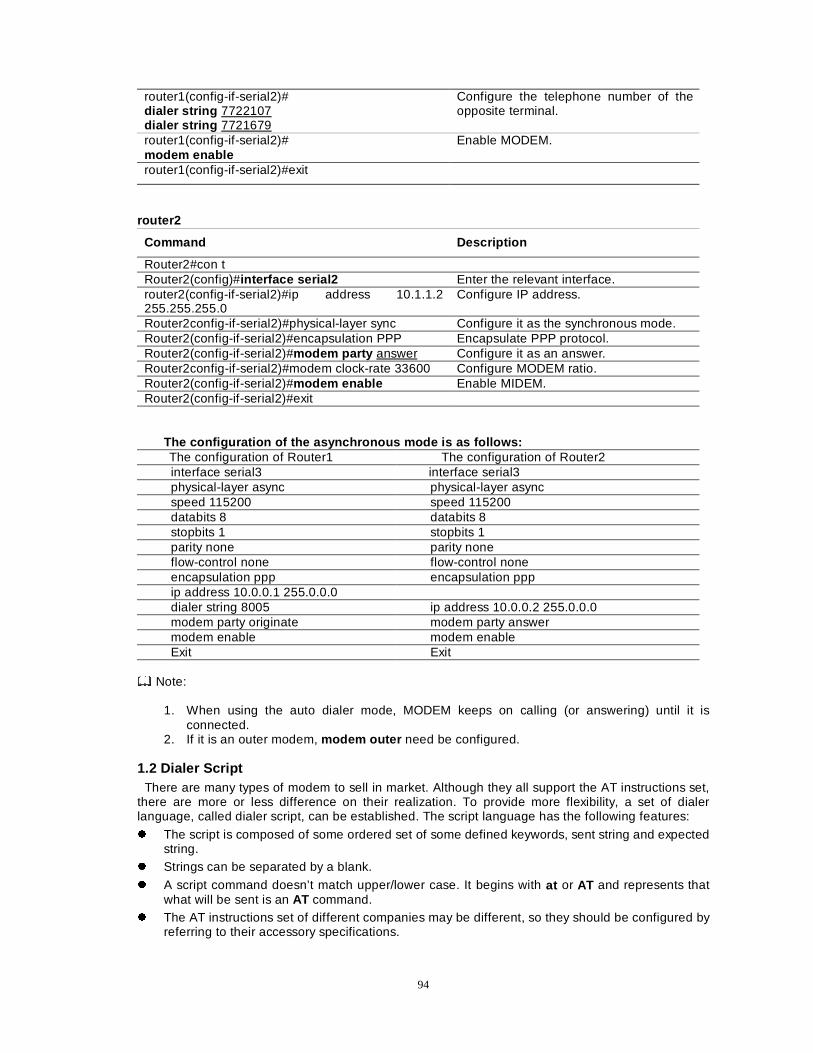
94
router1(config-if-serial2)# dialer string 7722107 dialer string 7721679
Configure the telephone number of the opposite terminal.
router1(config-if-serial2)# modem enable
Enable MODEM.
router1(config-if-serial2)#exit
router2
Command Description
Router2#con t Router2(config)#interface serial2 Enter the relevant interface. router2(config-if-serial2)#ip address 10.1.1.2 255.255.255.0
Configure IP address.
Router2config-if-serial2)#physical-layer sync Configure it as the synchronous mode. Router2(config-if-serial2)#encapsulation PPP Encapsulate PPP protocol. Router2(config-if-serial2)#modem party answer Configure it as an answer. Router2config-if-serial2)#modem clock-rate 33600 Configure MODEM ratio. Router2(config-if-serial2)#modem enable Enable MIDEM. Router2(config-if-serial2)#exit
The configuration of the asynchronous mode is as follows: The configuration of Router1 The configuration of Router2 interface serial3 interface serial3 physical-layer async physical-layer async speed 115200 speed 115200 databits 8 databits 8 stopbits 1 stopbits 1 parity none parity none flow-control none flow-control none encapsulation ppp encapsulation ppp ip address 10.0.0.1 255.0.0.0 dialer string 8005 ip address 10.0.0.2 255.0.0.0 modem party originate modem party answer modem enable modem enable Exit Exit
Note:
1. When using the auto dialer mode, MODEM keeps on calling (or answering) until it is
connected. 2. If it is an outer modem, modem outer need be configured.
1.2 Dialer Script There are many types of modem to sell in market. Although they all support the AT instructions set, there are more or less difference on their realization. To provide more flexibility, a set of dialer language, called dialer script, can be established. The script language has the following features:
z The script is composed of some ordered set of some defined keywords, sent string and expected string.
z Strings can be separated by a blank.
z A script command doesn’t match upper/lower case. It begins with at or AT and represents that what will be sent is an AT command.
z The AT instructions set of different companies may be different, so they should be configured by referring to their accessory specifications.
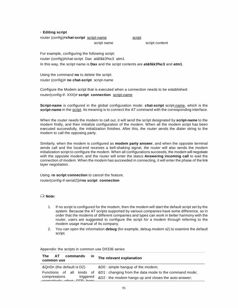
95
· Editing script router (config)#chat-script script-name script
script name script content
For example, configuring the following script: router (config)#chat-script Dax at&f&k3%c3 atm1
In this way, the script name is Dax and the script contents are at&f&k3%c3 and atm1 .
Using the command no to delete the script:
router (config)# no chat-script script-name Configure the Modem script that is executed when a connection needs to be established:
router(config-if- XXX)# script connection script-name
Script-name is configured in the global configuration mode: chat-script script-name, which is the script-name in the script. Its meaning is to connect the AT command with the corresponding interface.
When the router needs the modem to call out, it will send the script designated by script-name to the modem firstly, and then initialize configuration of the modem. When all the modem script has been executed successfully, the initialization finishes. After this, the router sends the dialer string to the modem to call the opposing party.
Similarly, when the modem is configured as modem party answer , and when the opposite terminal sends call and the local-end receives a bell-shaking signal, the router will also sends the modem initialization script to configure the modem. When all configurations succeeds, the modem will negotiate with the opposite modem, and the router will enter the status Answering incoming call to wait the connection of modem. When the modem has succeeded in connecting, it will enter the phase of the link layer negotiation.
Using no script connection to cancel the feature.
router(config-if-serial2))#no script connection
Note:
1. If no script is configured for the modem, then the modem will start the default script set by the system. Because the AT scripts supported by various companies have some difference, so in order that the modems of different companies and types can work in better harmony with the router, users are suggested to configure the script for a modem through referring to the modem usage manual of its company.
2. You can open the information debug (for example, debug modem s2) to examine the default script.
Appendix: the scripts in common use DX336 series
The AT commands in common use
The relevant explanation
&QnDn (the default is D2)
Functions of all kinds of compressions triggered respectively when DTR hops
&D0 : simple hangup of the modem;
&D1 : changing from the data mode to the command mode;
&D2 : the modem hangs up and closes the auto-answer;
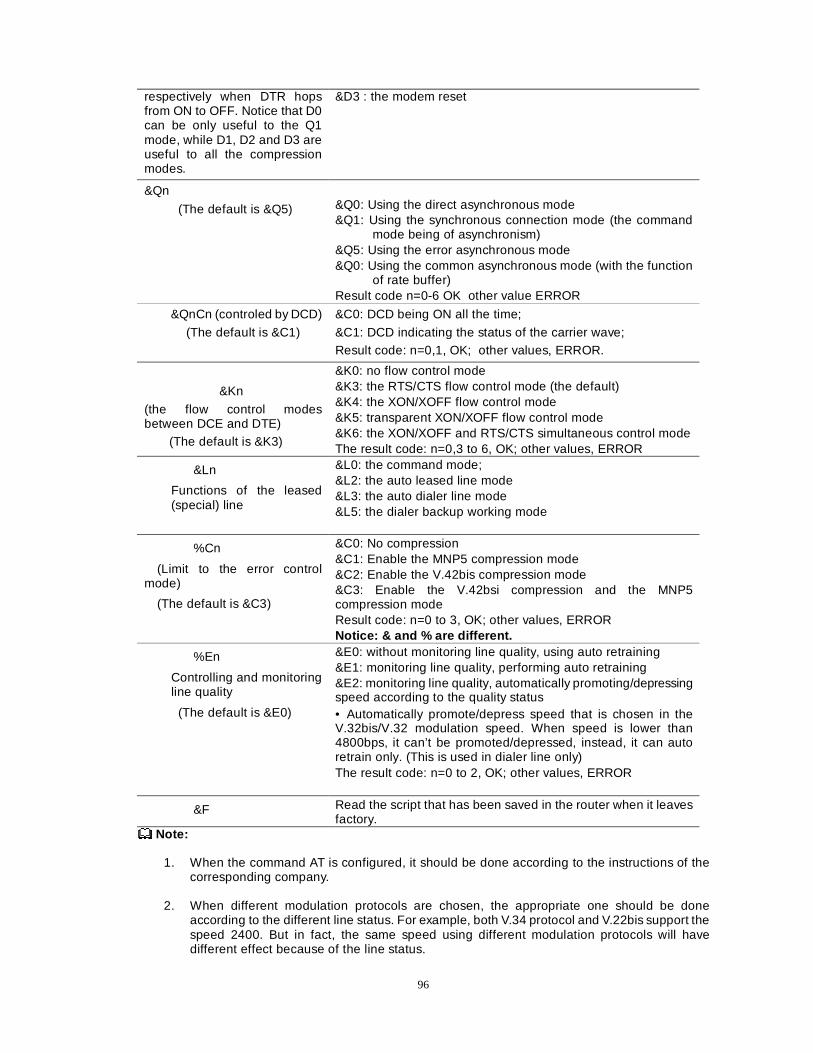
96
respectively when DTR hops from ON to OFF. Notice that D0 can be only useful to the Q1 mode, while D1, D2 and D3 are useful to all the compression modes.
&D3 : the modem reset
&Qn
(The default is &Q5)
&Q0: Using the direct asynchronous mode &Q1: Using the synchronous connection mode (the command
mode being of asynchronism) &Q5: Using the error asynchronous mode &Q0: Using the common asynchronous mode (with the function
of rate buffer) Result code n=0-6 OK other value ERROR
&QnCn (controled by DCD)
(The default is &C1)
&C0: DCD being ON all the time;
&C1: DCD indicating the status of the carrier wave; Result code: n=0,1, OK; other values, ERROR.
&Kn
(the flow control modes between DCE and DTE)
(The default is &K3)
&K0: no flow control mode &K3: the RTS/CTS flow control mode (the default) &K4: the XON/XOFF flow control mode &K5: transparent XON/XOFF flow control mode &K6: the XON/XOFF and RTS/CTS simultaneous control mode The result code: n=0,3 to 6, OK; other values, ERROR
&Ln
Functions of the leased (special) line
&L0: the command mode; &L2: the auto leased line mode &L3: the auto dialer line mode &L5: the dialer backup working mode
%Cn
(Limit to the error control mode)
(The default is &C3)
&C0: No compression &C1: Enable the MNP5 compression mode &C2: Enable the V.42bis compression mode &C3: Enable the V.42bsi compression and the MNP5 compression mode Result code: n=0 to 3, OK; other values, ERROR Notice: & and % are different.
%En
Controlling and monitoring line quality
(The default is &E0)
&E0: without monitoring line quality, using auto retraining &E1: monitoring line quality, performing auto retraining &E2: monitoring line quality, automatically promoting/depressing speed according to the quality status • Automatically promote/depress speed that is chosen in the V.32bis/V.32 modulation speed. When speed is lower than 4800bps, it can’t be promoted/depressed, instead, it can auto retrain only. (This is used in dialer line only) The result code: n=0 to 2, OK; other values, ERROR
&F Read the script that has been saved in the router when it leaves factory.
Note: 1. When the command AT is configured, it should be done according to the instructions of the
corresponding company. 2. When different modulation protocols are chosen, the appropriate one should be done
according to the different line status. For example, both V.34 protocol and V.22bis support the speed 2400. But in fact, the same speed using different modulation protocols will have different effect because of the line status.
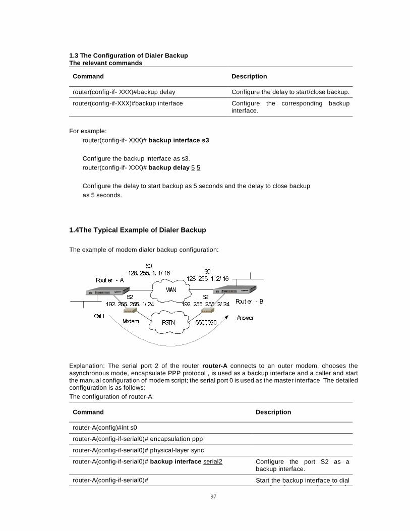
97
1.3 The Configuration of Dialer Backup The relevant commands
Command Description
router(config-if- XXX)#backup delay Configure the delay to start/close backup.
router(config-if-XXX)#backup interface Configure the corresponding backup interface.
For example:
router(config-if- XXX)# backup interface s3
Configure the backup interface as s3. router(config-if- XXX)# backup delay 5 5
Configure the delay to start backup as 5 seconds and the delay to close backup
as 5 seconds.
1.4The Typical Example of Dialer Backup
The example of modem dialer backup configuration:
:$1
3671
5RXW HUÎ$
5RXW HUÎ%
0RGHP
6�
���� ���� �� �� �� 6�
���� ���� �� �� ��
6�
���� ���� ���� �� ��
6�
���� ���� ���� �� ��
�������
&DO O $QVZHU
Explanation: The serial port 2 of the router router-A connects to an outer modem, chooses the asynchronous mode, encapsulate PPP protocol , is used as a backup interface and a caller and start the manual configuration of modem script; the serial port 0 is used as the master interface. The detailed configuration is as follows: The configuration of router-A:
Command Description
router-A(config)#int s0
router-A(config-if-serial0)# encapsulation ppp
router-A(config-if-serial0)# physical-layer sync
router-A(config-if-serial0)# backup interface serial2 Configure the port S2 as a backup interface.
router-A(config-if-serial0)# Start the backup interface to dial ft th t i t f i
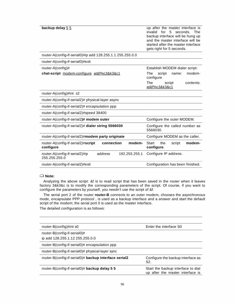
98
backup delay 5 5 up after the master interface is invalid for 5 seconds. The backup interface will be hung up and the master interface will be started after the master interface gets right for 5 seconds.
router-A(config-if-serial0)#ip add 128.255.1.1 255.255.0.0
router-A(config-if-serial0)#exit
router-A(config)#
chat-script modem-configure at&f%c3&k3&c1
Establish MODEM dialer script:
The script name: modem-configure
The script contents: at&f%c3&k3&c1
router-A(config)#int s2
router-A(config-if-serial2)# physical-layer async
router-A(config-if-serial2)# encapsulation ppp
router-A(config-if-serial2)#speed 38400
router-A(config-if-serial2)# modem outer Configure the outer MODEM.
router-A(config-if-serial2)# dialer string 5566030 Configure the called number as 5566030.
router-A(config-if-serial2)#modem party originate Configure MODEM as the caller.
router-A(config-if-serial2)#script connection modem-configure
Start the script modem-configure .
router-A(config-if-serial2)#ip address 192.255.255.1 255.255.255.0
Configure IP address.
router-A(config-if-serial2)#exit Configuration has been finished.
Note: Analyzing the above script: &f is to read script that has been saved in the router when it leaves
factory 3&k3&c is to modify the corresponding parameters of the script. Of course, if you want to configure the parameters by yourself, you needn’t use the script of &f.
The serial port 2 of the router router-B connects to an outer modem, chooses the asynchronous mode, encapsulate PPP protocol , is used as a backup interface and a answer and start the default script of the modem; the serial port 0 is used as the master interface.
The detailed configuration is as follows:
router-B(config)#int s0 Enter the interface S0
router-B(config-if-serial0)# ip add 128.255.1.12 255.255.0.0
router-B(config-if-serial0)# encapsulation ppp
router-B(config-if-serial0)# physical-layer sync
router-B(config-if-serial0)# backup interface serial2 Configure the backup interface as S2.
router-B(config-if-serial0)# backup delay 5 5 Start the backup interface to dial up after the master interface is
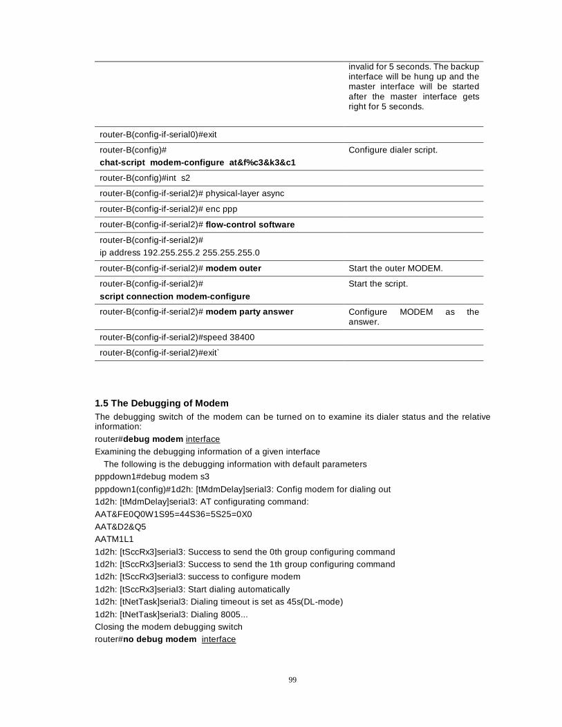
99
invalid for 5 seconds. The backup interface will be hung up and the master interface will be started after the master interface gets right for 5 seconds.
router-B(config-if-serial0)#exit
router-B(config)#
chat-script modem-configure at&f%c3&k3&c1
Configure dialer script.
router-B(config)#int s2
router-B(config-if-serial2)# physical-layer async
router-B(config-if-serial2)# enc ppp
router-B(config-if-serial2)# flow-control software
router-B(config-if-serial2)#
ip address 192.255.255.2 255.255.255.0
router-B(config-if-serial2)# modem outer Start the outer MODEM.
router-B(config-if-serial2)#
script connection modem-configure
Start the script.
router-B(config-if-serial2)# modem party answer Configure MODEM as the answer.
router-B(config-if-serial2)#speed 38400
router-B(config-if-serial2)#exit`
1.5 The Debugging of Modem The debugging switch of the modem can be turned on to examine its dialer status and the relative information:
router#debug modem interface
Examining the debugging information of a given interface
The following is the debugging information with default parameters pppdown1#debug modem s3
pppdown1(config)#1d2h: [tMdmDelay]serial3: Config modem for dialing out 1d2h: [tMdmDelay]serial3: AT configurating command:
AAT&FE0Q0W1S95=44S36=5S25=0X0
AAT&D2&Q5 AATM1L1
1d2h: [tSccRx3]serial3: Success to send the 0th group configuring command 1d2h: [tSccRx3]serial3: Success to send the 1th group configuring command 1d2h: [tSccRx3]serial3: success to configure modem
1d2h: [tSccRx3]serial3: Start dialing automatically 1d2h: [tNetTask]serial3: Dialing timeout is set as 45s(DL-mode)
1d2h: [tNetTask]serial3: Dialing 8005... Closing the modem debugging switch router#no debug modem interface
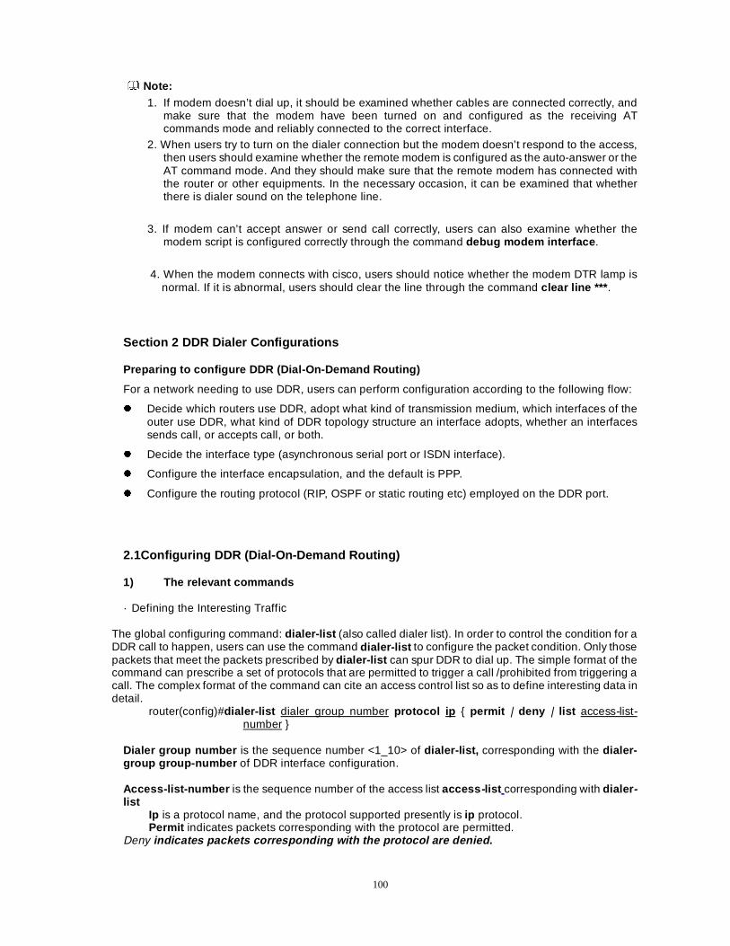
100
Note: 1. If modem doesn’t dial up, it should be examined whether cables are connected correctly, and
make sure that the modem have been turned on and configured as the receiving AT commands mode and reliably connected to the correct interface.
2. When users try to turn on the dialer connection but the modem doesn’t respond to the access, then users should examine whether the remote modem is configured as the auto-answer or the AT command mode. And they should make sure that the remote modem has connected with the router or other equipments. In the necessary occasion, it can be examined that whether there is dialer sound on the telephone line.
3. If modem can’t accept answer or send call correctly, users can also examine whether the modem script is configured correctly through the command debug modem interface .
4. When the modem connects with cisco, users should notice whether the modem DTR lamp is
normal. If it is abnormal, users should clear the line through the command clear line *** .
Section 2 DDR Dialer Configurations Preparing to configure DDR (Dial-On-Demand Routing)
For a network needing to use DDR, users can perform configuration according to the following flow:
z Decide which routers use DDR, adopt what kind of transmission medium, which interfaces of the outer use DDR, what kind of DDR topology structure an interface adopts, whether an interfaces sends call, or accepts call, or both.
z Decide the interface type (asynchronous serial port or ISDN interface).
z Configure the interface encapsulation, and the default is PPP.
z Configure the routing protocol (RIP, OSPF or static routing etc) employed on the DDR port.
2.1Configuring DDR (Dial-On-Demand Routing) 1) The relevant commands
· Defining the Interesting Traffic
The global configuring command: dialer-list (also called dialer list). In order to control the condition for a DDR call to happen, users can use the command dialer-list to configure the packet condition. Only those packets that meet the packets prescribed by dialer-list can spur DDR to dial up. The simple format of the command can prescribe a set of protocols that are permitted to trigger a call /prohibited from triggering a call. The complex format of the command can cite an access control list so as to define interesting data in detail.
router(config)#dialer-list dialer group number protocol ip { permit | deny | list access-list-number }
Dialer group number is the sequence number <1_10> of dialer-list, corresponding with the dialer-group group-number of DDR interface configuration. Access-list-number is the sequence number of the access list access -list corresponding with dialer -list
Ip is a protocol name, and the protocol supported presently is ip protocol. Permit indicates packets corresponding with the protocol are permitted.
Deny indicates packets corresponding with the protocol are denied.
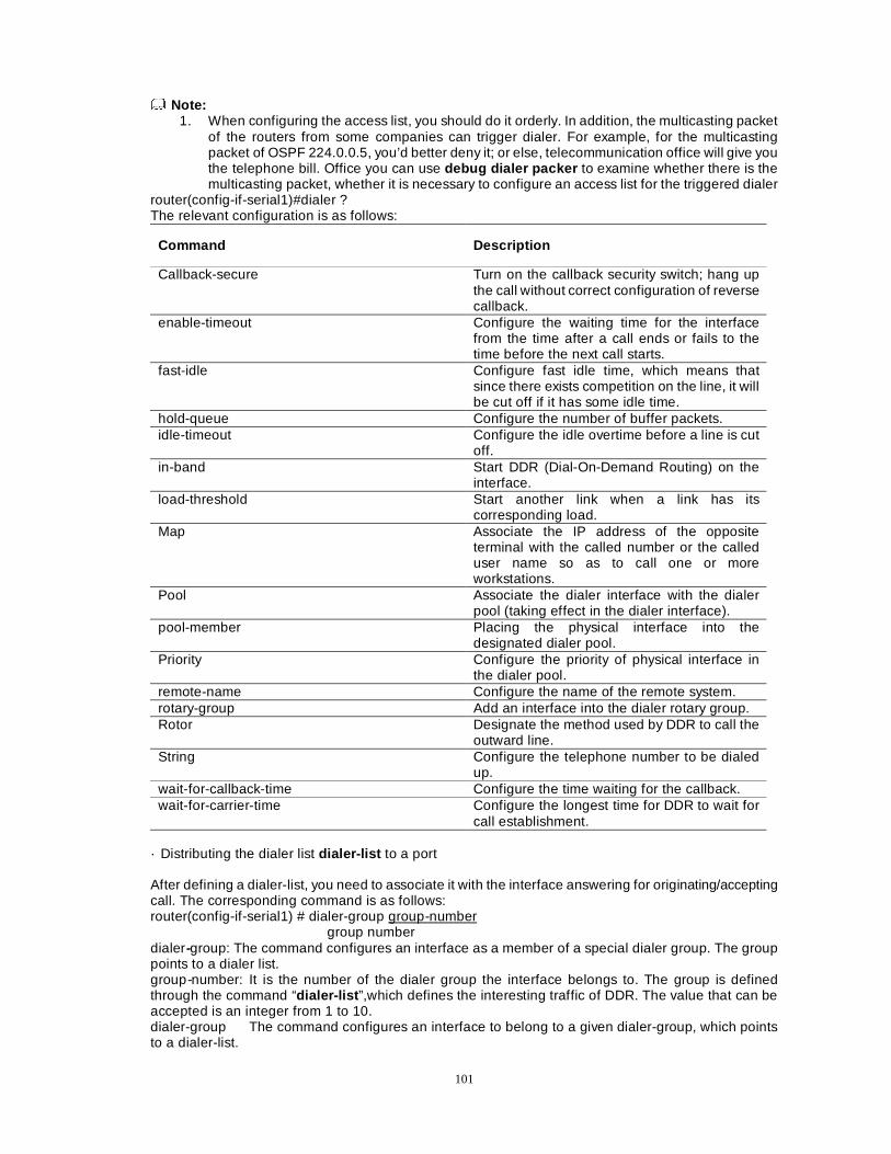
101
Note: 1. When configuring the access list, you should do it orderly. In addition, the multicasting packet
of the routers from some companies can trigger dialer. For example, for the multicasting packet of OSPF 224.0.0.5, you’d better deny it; or else, telecommunication office will give you the telephone bill. Office you can use debug dialer packer to examine whether there is the multicasting packet, whether it is necessary to configure an access list for the triggered dialer
router(config-if-serial1)#dialer ? The relevant configuration is as follows:
Command Description
Callback-secure Turn on the callback security switch; hang up the call without correct configuration of reverse callback.
enable-timeout Configure the waiting time for the interface from the time after a call ends or fails to the time before the next call starts.
fast-idle Configure fast idle time, which means that since there exists competition on the line, it will be cut off if it has some idle time.
hold-queue Configure the number of buffer packets. idle-timeout Configure the idle overtime before a line is cut
off. in-band Start DDR (Dial-On-Demand Routing) on the
interface. load-threshold Start another link when a link has its
corresponding load. Map Associate the IP address of the opposite
terminal with the called number or the called user name so as to call one or more workstations.
Pool Associate the dialer interface with the dialer pool (taking effect in the dialer interface).
pool-member Placing the physical interface into the designated dialer pool.
Priority Configure the priority of physical interface in the dialer pool.
remote-name Configure the name of the remote system. rotary-group Add an interface into the dialer rotary group. Rotor Designate the method used by DDR to call the
outward line. String Configure the telephone number to be dialed
up. wait-for-callback-time Configure the time waiting for the callback. wait-for-carrier-time Configure the longest time for DDR to wait for
call establishment. · Distributing the dialer list dialer-list to a port After defining a dialer-list, you need to associate it with the interface answering for originating/accepting call. The corresponding command is as follows: router(config-if-serial1) # dialer-group group-number
group number dialer-group: The command configures an interface as a member of a special dialer group. The group points to a dialer list. group-number: It is the number of the dialer group the interface belongs to. The group is defined through the command “dialer-list ”,which defines the interesting traffic of DDR. The value that can be accepted is an integer from 1 to 10. dialer-group The command configures an interface to belong to a given dialer-group, which points to a dialer-list.
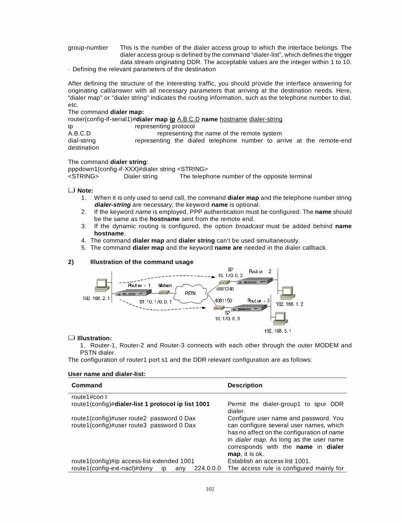
102
group-number This is the number of the dialer access group to which the interface belongs. The dialer access group is defined by the command “dialer-list”, which defines the trigger data stream originating DDR. The acceptable values are the integer within 1 to 10.
· Defining the relevant parameters of the destination After defining the structure of the interesting traffic, you should provide the interface answering for originating call/answer with all necessary parameters that arriving at the destination needs. Here, “dialer map” or “dialer string” indicates the routing information, such as the telephone number to dial, etc. The command dialer map: router(config-if-serial1)#dialer map ip A.B.C.D name hostname dialer-string ip representing protocol A.B.C.D representing the name of the remote system dial-string representing the dialed telephone number to arrive at the remote-end destination The command dialer string : pppdown1(config-if-XXX)#dialer string <STRING> <STRING> Dialer string The telephone number of the opposite terminal Note:
1. When it is only used to send call, the command dialer map and the telephone number string dialer-string are necessary; the keyword name is optional.
2. If the keyword name is employed, PPP authentication must be configured. The name should be the same as the hostname sent from the remote end.
3. If the dynamic routing is configured, the option broadcast must be added behind name hostname .
4. The command dialer map and dialer string can’t be used simultaneously. 5. The command dialer map and the keyword name are needed in the dialer callback.
2) Illustration of the command usage
3671
0RGHP5RXW HU�
5RXW HU�
5RXW HU��������
�������
6�� ��� ���� �� �
6�
��� ���� �� �
6�
��� ���� �� �
���� ���� �� �
���� ���� �� �
���� ���� �� �
Illustration:
1. Router-1, Router-2 and Router-3 connects with each other through the outer MODEM and PSTN dialer.
The configuration of router1 port s1 and the DDR relevant configuration are as follows: User name and dialer-list:
Command Description
route1#con t route1(config)#dialer-list 1 protocol ip list 1001 Permit the dialer-group1 to spur DDR
dialer. route1(config)#user route2 password 0 Dax route1(config)#user route3 password 0 Dax
Configure user name and password. You can configure several user names, which has no affect on the configuration of name in dialer map. As long as the user name corresponds with the name in dialer map , it is ok.
route1(config)#ip access-list extended 1001 Establish an access list 1001. route1(config-ext-nacl)#deny ip any 224.0.0.0 The access rule is configured mainly for
103
0.255.255.255 route1(config-ext-nacl)#permit ip any any
that some multicasting packets that can trigger DDR dialer.
The configuration of the interface:
Command Description
route1(config)#interface serial1 Enter the interface s1. route1(config-if-serial1)#physical-layer async Configure it as the asynchronous mode route1(config-if-serial1)#speed 115200 Speed is 115200. route1(config-if-serial1)#databits 8 8 data bits route1(config-if-serial1)#stopbits 1 1 stop bit route1(config-if-serial1)#parity none The parity bit is NULL. route1(config-if-serial1)#flow-control none Configure the flow control as NULL. route1(config-if-serial1)#encapsulation ppp Encapsulate PPP protocol. route1(config-if-serial1)#ip address 10.170.0.1 255.0.0.0
Configure IP address.
route1(config-if-serial1)#modem outer Enable the outer MODEM to be effective. route1(config-if-serial1)#dialer in-band Start DDR on the interface route1(config-if-serial1)# dialer idle-timeout 100
DDR hangs up link when no data stream passes through the link within 100 seconds after a call is created.
route1(config-if-serial1)# dialer fast-idle 30
After the current call has been idle for 30 seconds, the call gives place to another one that is waiting.
route1(config-if-serial1)# dialer map ip 10.170.0.2 name route2 4081240
Send the call with telephone number 4031240 to router2 with the address 10.170.0.2.
route1(config-if-serial1)# dialer map ip 10.170.0.3 name route3 4081150
Send the call with telephone number 4081150 to router3 with the address 10.170.0.3.
route1(config-if-serial1)#dialer-group 1 The interface s1 belongs to the dialer
group 1 (Dial up only when the data stream according with the dialer-group1 is triggered.)
route1(config-if-serial1)#ppp authentication chap Configure chap authentication, Configure the command as the chap originator.
route1(config-if-serial1)#ppp chap hostname route1 Configure the authenticated name corresponding with the name in the opposite terminal dialer map.
route1(config-if-serial1)#exit Configuring dialer triggering route : route1(config)#ip route 192.168.3.0 255.255.255.0 10.170.0.3 route1(config)#ip route 192.168.1.0 255.255.255.0 10.170.0.2 Note:
1.The above two routes are used to trigger the different telephone numbers that the different directions of data stream trigger.
2.During the course, after the route1 dials on the outer modem of the route2 and constructs an access to the route2, if there is no data sent through the port s1 within 100 seconds (namely exceeding the value of idle-timeout ), the router1 will trigger modem1 to automatically disconnect the connection with the modem2 of the route2. Within the idle time, if the route1 receives the data stream to trigger calling the route3, the timer fast-idle will start. Within the 30 seconds the timer fast-idle times, if there is no data sent to the route2 through the port s1, the route1 will disconnect the connection with the route2 and call the route3. 3.For the answer, it should be configured as the authentication originator. At the moment of callback, two same names can’t be configured in dialer map on the side of callbacker. Besides the above, of
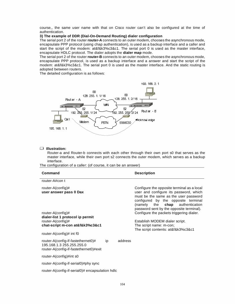
104
course,, the same user name with that on Cisco router can’t also be configured at the time of authentication. 3) The example of DDR (Dial-On-Demand Routing) dialer configuration The serial port 2 of the router router-A connects to an outer modem, chooses the asynchronous mode, encapsulate PPP protocol (using chap authentication), is used as a backup interface and a caller and start the script of the modem: at&f&k3%c3&c1. The serial port 0 is used as the master interface, encapsulate HDLC protocol. The dialer adopts the dialer map mode. The serial port 2 of the router router-B connects to an outer modem, chooses the asynchronous mode, encapsulate PPP protocol, is used as a backup interface and a answer and start the script of the modem: at&f&k3%c3&c1. The serial port 0 is used as the master interface. And the static routing is adopted between routers. The detailed configuration is as follows:
:$1
3671
5RXW HUÎ$
5RXW HUÎ%
0RGHP
6�
���� ���� �� �� �� 6�
���� ���� �� �� ��
6�
���� ���� ���� �� ��
6�
���� ���� ���� �� ��
�������&DO O $FNQRZO HGJH
���� ���� �� �
���� ���� �� �
Illustration:
Router-a and Router-b connects with each other through their own port s0 that serves as the master interface, while their own port s2 connects the outer modem, which serves as a backup interface.
The configuration of a caller: (of course, it can be an answer)
Command Description
router-A#con t
router-A(config)# user answer pass 0 Dax
Configure the opposite terminal as a local user and configure its password, which must be the same as the user password configured by the opposite terminal (namely the chap authentication password sent by the opposite terminal).
router-A(config)# dialer-list 1 protocol ip permit
Configure the packets triggering dialer.
router-A(config)# chat-script m-con at&f&k3%c3&c1
Establish MODEM dialer script. The script name: m-con; The script contents: at&f&k3%c3&c1
router-A(config)# int f0
router-A(config-if-fastethernet0)# ip address 195.168.1.3 255.255.255.0
router-A(config-if-fastethernet0)#exit
router-A(config)#int s0
router-A(config-if-serial0)#phy sync
router-A(config-if-serial0)# encapsulation hdlc
105
router-A(config-if-serial0)# ip address 128.255.1.1 255.255.0.0
router-A(config-if-serial0)# backup interface serial2
Use the serial port S2 as the backup port.
router-A(config-if-serial0)# backup delay 5 20
It represents that when the master interface is invalid, the backup interface will active after 5 seconds; when the master interface line gets right, the backup interface will hang up after 20 seconds and then the master interface will active.
router-A(config-if-serial0)#exit
router-A(config)#int s2
router-A(config-if-serial2)# physical-layer async
router-A(config-if-serial2)# encapsulation ppp
router-A(config-if-serial2)# ppp authentication chap
router-A(config-if-serial2)# ppp chap hostname caller
router-A(config-if-serial2)# ip address 192.255.255.1 255.255.255.0
router-A(config-if-serial2)# modem outer
Configure the outer modem.
router-A(config-if-serial2)# dialer in-band
Enable DDR configuration effective on the interface.
router-A(config-if-serial2)# dialer map ip 192.255.255.2 name answer 5148120
Configure a dialer association. IP address of the opposite terminal is 192.255.255.2, the authentication user name is answer and the telephone number to dial is 5148120. If the dynamic routing is employed, don’t forget to add a word broadcast behind the telephone number.
router-A(config-if-serial2)# script connection m-con
Configure MODEM script.
router-A(config-if-serial2)# dialer-group 1
Define the interesting traffic that triggers DDR.
router-A(config-if-serial2)#exit
router-A(config)# ip route 193.168.0.0 255.255.0.0 serial0 router-A(config)# ip route 193.168.0.0 255.255.0.0 serial2 200
Add the static route.
Note:
1. When the static routing is adopted, ip unnumber is applied to some interface and a route
triggers dialer, a host route or a more concrete route should be added to enable packets to send out from the dial-port to trigger dialer.
106
Command Description
router-B#con t
router-B(config)#user caller password 0 Dax
Configure the opposite terminal as a local user and configure its password, which must be the same as the user password configured by the opposite terminal (namely the chap authentication password sent by the opposite terminal).
router-B(config)#dialer-list 1 protocol ip permit Configure the packets triggering dialer.
router-B(config)# chat-script m-con at&f&k3%c3&c1
Establish MODEM dialer script; The script name: m-con The script contents: at&f&k3%c3&c1
router-B Config # int f0
router-B(config-if-fastethernet0)# ip address 193.168.2.3 255.255.255.0
router-B(config-if-fastethernet0)#exit
router-B(config)#int s0
router-B(config-if-serial0)#phy sync
router-B(config-if-serial0)#encapsulation hdlc
router-B(config-if-serial0)#clock rate 64000
router-B(config-if-serial0)#ip address 128.255.1.2 255.255.0.0
router-B(config-if-serial0)#backup interface serial2 Use the serial port S2 as the backup port.
router-A(config-if-serial0)# backup delay 5 20
It represents that when the master interface is invalid, the backup interface will activet after 5 seconds; when the master interface line gets right, the backup interface will hang up after 20 seconds and then the master interface will active.
router-B(config-if-serial0)#exit
router-B(config)#int s2
router-B(config-if-serial2)# physical-layer async
router-B(config-if-serial2)# encapsulation ppp
router-B(config-if-serial2)# ppp authentication chap Configure chap authentication.
router-B(config-if-serial2)# ppp chap hostname answer Configure the name of chap authentication.
router-B(config-if-serial2)# dialer map ip 192.255.255.1 name caller( 5148343)
Of course, if this side serves only as an answer, it will be not necessary to configure the telephone number to dial.
router-B(config-if-serial2)# ip address 192.255.255.1 255.255.255.0
router-B(config-if-serial2)#modem outer Configure the outer modem.
107
router-B(config-if-serial2)# dialer in-band
Enable DDR configuration effective on the interface.
router-B(config-if-serial2)#script connection m-con Configure MODEM script.
router-B(config-if-serial2)#dialer-group 1 Define the interesting traffic that triggers DDR.
router-B(config-if-serial2)#exit
router-B(config)#ip route 195.168.0.0 255.255.0.0 serial0 router-B(config)#ip route 195.168.0.0 255.255.0.0 serial2
Add the static route
� Noticeable points:
z If modem doesn’t dial up, users should examine whether cables are connected correctly, should make sure that modem has been turned on, it has been configured as the mode the modem can accept the AT commands and it has reliably connects with the correct interface.
z When users try to open dialer connection but modem has no response to the access, users should examine whether the remote modem is configured as auto-answer or the AT command mode. They should make sure that the remote modem has connected with the router or other equipments. At the necessary occasion, they can also examine whether there is dialer sound on the telephone line.
z If modem can’t accept answer or send call correctly, users can also examine whether the modem script is configured correctly through the command debug modem interface .
z When dialer backup interface doesn’t dial up, then dcd is down , but its flag Flags is often in the status of up (spoofing) . However, at the moment, the port isn’t up really. Only when the master interface is down and there is data to trigger, then the dialer backup interface can dial. When it is connected correctly, the flags will be in the status of up .
2.2 Dialer Callback PPP reverse callback provides a kind of client/server relation between the two ends connected in terms of the point-to-point mode. The function of PPP reverse callback permits the router to ask the opposite terminal router connected by dialer to call back. The feature can be used to control access and save the charge of the remote call between routers The operation and procedure of reverse callback: 1. The reverse callback client originates a call. In the LCP negotiation phase of PPP, a client can
use the reverse callback option to request the reverse callback
2. The reverse callback server determines the reverse callback request and examines the configuration of itself to validate whether the reverse callback is employed.
3. The reverse callback client and server process the authentication through CHAP or PAP. A user name is used to distinguish the dialer string used by the callback.
4. After the success of the first authentication, the router used as the reverse callback server will distinguish the dialer string used by the reverse callback. The reverse callback server compares user names with the host names in the dialer-mapping list.
5. If “dialer callback-secure” is not started, the reverse callback server will maintain the initial call when the reverse callback isn’t configured for the authenticated user name; or else, the reverse callback server will hang up the initial call.
6. The reverse callback server uses dialer string to originate a reverse callback. If it fails, it will not try
to call again. During the course of returning a call back, the reverse callback doesn’t process LCP
negotiation of PPP
7. Process to call.
8. Keep on connecting.
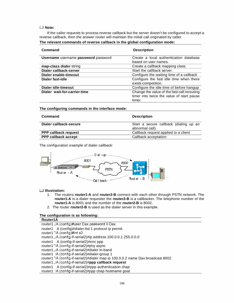
108
Note: If the caller requests to process reverse callback but the server doesn’t be configured to accept a
reverse callback, then the answer router will maintain the initial call originated by caller. The relevant commands of reverse callback in the global configuration mode:
Command Description
Username username password password Create a local authentication database based on user names.
map-class dialer string Create a callback mapping class. Dialer callback-server Start the callback server. Dialer enable-timeout Configure the waiting time of a callback Dialer fast-idle Configure the fast idle time when there
exists competition. Dialer idle-timeout Configure the idle time of before hangup Dialer wait-for-carrier-time Change the value of the fast call rerouting
timer into twice the value of start pause timer.
The configuring commands in the interface mode:
Command Description
Dialer callback-secure Start a secure callback (dialing up an abnormal call).
PPP callback request Callback request applied to a client PPP callback accept Callback acceptation
The configuration example of dialer callback:
5RXW HUÎ$
5RXW HUÎ%
3671
��������
'L DO � XS
&DO O EDFN
Illustration:
1. The routers router1-A and router2-B connect with each other through PSTN network. The router1-A is a dialer requester the router2-B is a callbacker. The telephone number of the router1-A is 8001 and the number of the router2-B is 8002.
2. The router router2-B is used as the dialer server in this example.
The configuration is as following: Router1A router1�$ �FRQILJ��XVHU 'D[ SDVVZRUG � 'D[ router1ÉA (config)#dialer-list 1 protocol ip permit router1�$ �FRQILJ��LQW V� router1�$ �FRQILJ-if-serial2)#ip address 100.0.0.1 255.0.0.0 router1ÉA (config-if-serial2)#enc ppp router1�$ �FRQILJ-if-serial2)#phy async router1�$ �FRQILJ-if-serial2)#dialer in-band router1�$ �FRQILJ-if-serial2)#dialer-group 1 router1�$ �FRQILJ-if-serial2)#dialer map ip 100.0.0.2 name Dax broadcast 8002 router1�$ �FRQILJ-if-serial2)#ppp callback request router1ÉA (config-if-serial2)#ppp authentication chap router1�$ �FRQILJ-if-serial2)#ppp chap hostname goat
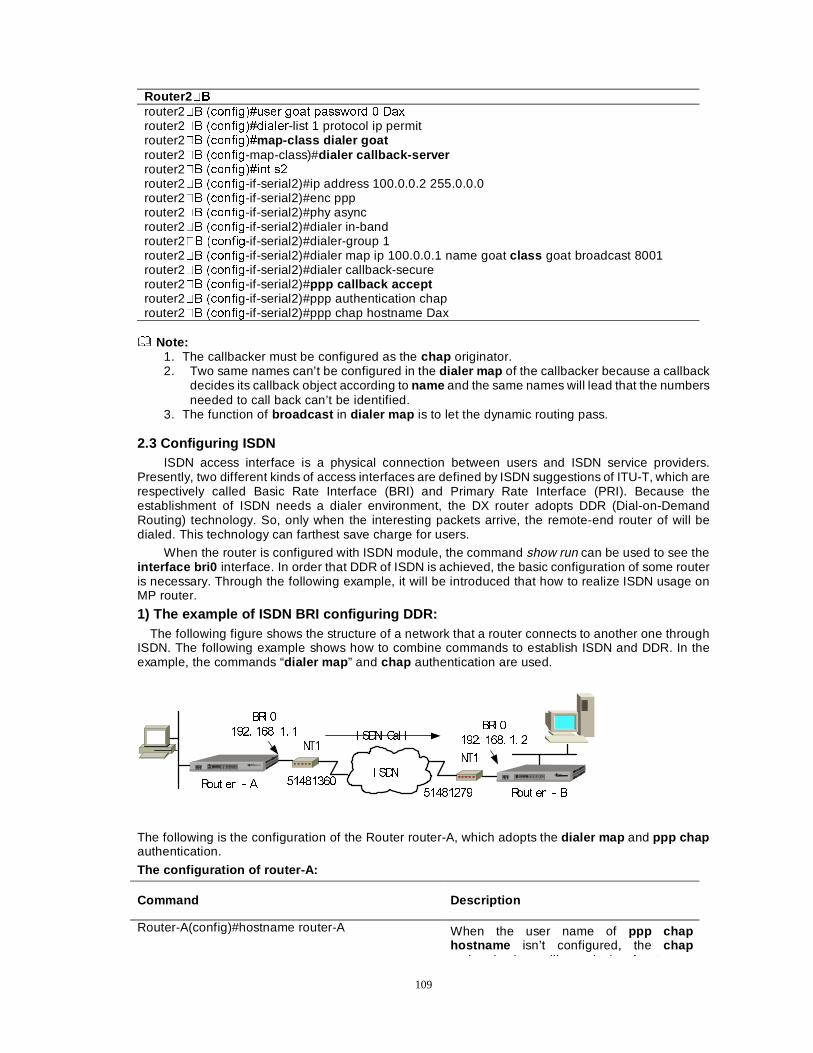
109
Router2 �% router2�% �FRQILJ��XVHU JRDW SDVVZRUG � 'D[ router2�% �FRQILJ��GLDOHU-list 1 protocol ip permit router2�% �FRQILJ��map-class dialer goat router2�% �FRQILJ-map-class)#dialer callback-server router2�% �FRQILJ��LQW V� router2�% �FRQILJ-if-serial2)#ip address 100.0.0.2 255.0.0.0 router2�% �FRQILJ-if-serial2)#enc ppp router2�% �FRQILJ-if-serial2)#phy async router2�% �FRQILJ-if-serial2)#dialer in-band router2�% �FRQILJ-if-serial2)#dialer-group 1 router2�% �FRQILJ-if-serial2)#dialer map ip 100.0.0.1 name goat class goat broadcast 8001 router2�% �FRQILJ-if-serial2)#dialer callback-secure router2�% �FRQILJ-if-serial2)#ppp callback accept router2�% �FRQILg-if-serial2)#ppp authentication chap router2�% �FRQILJ-if-serial2)#ppp chap hostname Dax
Note:
1. The callbacker must be configured as the chap originator. 2. Two same names can’t be configured in the dialer map of the callbacker because a callback
decides its callback object according to name and the same names will lead that the numbers needed to call back can’t be identified.
3. The function of broadcast in dialer map is to let the dynamic routing pass. 2.3 Configuring ISDN
ISDN access interface is a physical connection between users and ISDN service providers. Presently, two different kinds of access interfaces are defined by ISDN suggestions of ITU-T, which are respectively called Basic Rate Interface (BRI) and Primary Rate Interface (PRI). Because the establishment of ISDN needs a dialer environment, the DX router adopts DDR (Dial-on-Demand Routing) technology. So, only when the interesting packets arrive, the remote-end router of will be dialed. This technology can farthest save charge for users.
When the router is configured with ISDN module, the command show run can be used to see the interface bri0 interface. In order that DDR of ISDN is achieved, the basic configuration of some router is necessary. Through the following example, it will be introduced that how to realize ISDN usage on MP router.
1) The example of ISDN BRI configuring DDR: The following figure shows the structure of a network that a router connects to another one through
ISDN. The following example shows how to combine commands to establish ISDN and DDR. In the example, the commands “dialer map ” and chap authentication are used.
5RXW HUÎ$5RXW HUÎ%
, 6'1��������
��������
17�
17�
%5, �
���� ���� �� �%5, �
���� ���� �� �, 6'1 &DO O
The following is the configuration of the Router router-A, which adopts the dialer map and ppp chap authentication.
The configuration of router-A:
Command Description
Router-A(config)#hostname router-A
When the user name of ppp chap hostname isn’t configured, the chap
th ti ti ill d th h t
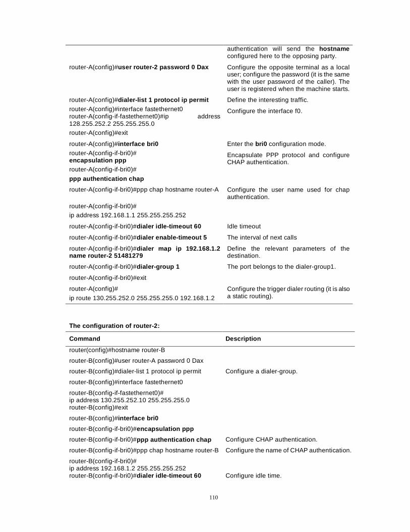
110
authentication will send the hostname configured here to the opposing party.
router-A(config)#user router-2 password 0 Dax Configure the opposite terminal as a local user; configure the password (it is the same with the user password of the caller). The user is registered when the machine starts.
router-A(config)#dialer-list 1 protocol ip permit Define the interesting traffic.
router-A(config)#interface fastethernet0 router-A(config-if-fastethernet0)#ip address 128.255.252.2 255.255.255.0 router-A(config)#exit
Configure the interface f0.
router-A(config)#interface bri0 Enter the bri0 configuration mode.
router-A(config-if-bri0)# encapsulation ppp router-A(config-if-bri0)#
ppp authentication chap
Encapsulate PPP protocol and configure CHAP authentication.
router-A(config-if-bri0)#ppp chap hostname router-A Configure the user name used for chap authentication.
router-A(config-if-bri0)# ip address 192.168.1.1 255.255.255.252
router-A(config-if-bri0)#dialer idle-timeout 60 Idle timeout
router-A(config-if-bri0)#dialer enable-timeout 5 The interval of next calls
router-A(config-if-bri0)#dialer map ip 192.168.1.2 name router-2 51481279
Define the relevant parameters of the destination.
router-A(config-if-bri0)#dialer-group 1 The port belongs to the dialer-group1.
router-A(config-if-bri0)#exit
router-A(config)#
ip route 130.255.252.0 255.255.255.0 192.168.1.2
Configure the trigger dialer routing (it is also a static routing).
The configuration of router-2:
Command Description
router(config)#hostname router-B
router-B(config)#user router-A password 0 Dax
router-B(config)#dialer-list 1 protocol ip permit Configure a dialer-group.
router-B(config)#interface fastethernet0
router-B(config-if-fastethernet0)# ip address 130.255.252.10 255.255.255.0
router-B(config)#exit
router-B(config)#interface bri0
router-B(config-if-bri0)#encapsulation ppp
router-B(config-if-bri0)#ppp authentication chap Configure CHAP authentication.
router-B(config-if-bri0)#ppp chap hostname router-B Configure the name of CHAP authentication.
router-B(config-if-bri0)# ip address 192.168.1.2 255.255.255.252
router-B(config-if-bri0)#dialer idle-timeout 60 Configure idle time.
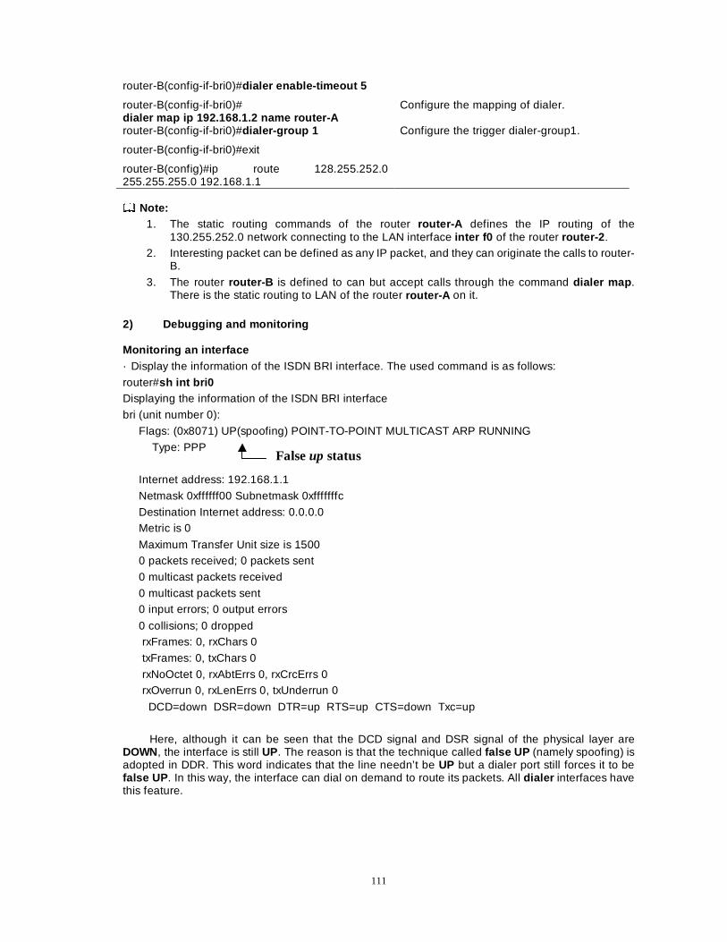
111
router-B(config-if-bri0)#dialer enable-timeout 5
router-B(config-if-bri0)# dialer map ip 192.168.1.2 name router-A
Configure the mapping of dialer.
router-B(config-if-bri0)#dialer-group 1 Configure the trigger dialer-group1.
router-B(config-if-bri0)#exit
router-B(config)#ip route 128.255.252.0 255.255.255.0 192.168.1.1
Note:
1. The static routing commands of the router router-A defines the IP routing of the 130.255.252.0 network connecting to the LAN interface inter f0 of the router router-2 .
2. Interesting packet can be defined as any IP packet, and they can originate the calls to router-B.
3. The router router-B is defined to can but accept calls through the command dialer map . There is the static routing to LAN of the router router-A on it.
2) Debugging and monitoring Monitoring an interface · Display the information of the ISDN BRI interface. The used command is as follows:
router#sh int bri0 Displaying the information of the ISDN BRI interface
bri (unit number 0):
Flags: (0x8071) UP(spoofing) POINT-TO-POINT MULTICAST ARP RUNNING
Type: PPP
Internet address: 192.168.1.1
Netmask 0xffffff00 Subnetmask 0xfffffffc
Destination Internet address: 0.0.0.0 Metric is 0
Maximum Transfer Unit size is 1500 0 packets received; 0 packets sent
0 multicast packets received
0 multicast packets sent 0 input errors; 0 output errors
0 collisions; 0 dropped rxFrames: 0, rxChars 0
txFrames: 0, txChars 0
rxNoOctet 0, rxAbtErrs 0, rxCrcErrs 0 rxOverrun 0, rxLenErrs 0, txUnderrun 0
DCD=down DSR=down DTR=up RTS=up CTS=down Txc=up
Here, although it can be seen that the DCD signal and DSR signal of the physical layer are DOWN, the interface is still UP. The reason is that the technique called false UP (namely spoofing) is adopted in DDR. This word indicates that the line needn’t be UP but a dialer port still forces it to be false UP . In this way, the interface can dial on demand to route its packets. All dialer interfaces have this feature.
False up status
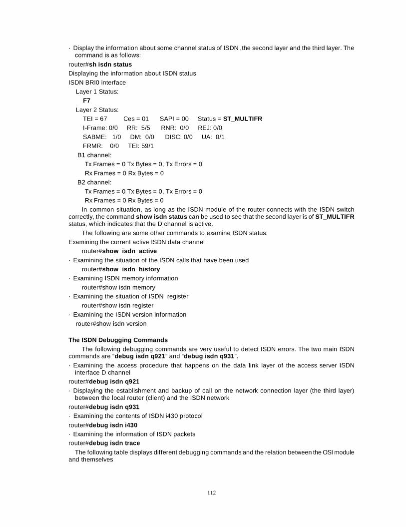
112
· Display the information about some channel status of ISDN ,the second layer and the third layer. The command is as follows:
router#sh isdn status Displaying the information about ISDN status
ISDN BRI0 interface
Layer 1 Status: F7 Layer 2 Status: TEI = 67 Ces = 01 SAPI = 00 Status = ST_MULTIFR
I-Frame: 0/0 RR: 5/5 RNR: 0/0 REJ: 0/0
SABME: 1/0 DM: 0/0 DISC: 0/0 UA: 0/1 FRMR: 0/0 TEI: 59/1
B1 channel: Tx Frames = 0 Tx Bytes = 0, Tx Errors = 0
Rx Frames = 0 Rx Bytes = 0
B2 channel:
Tx Frames = 0 Tx Bytes = 0, Tx Errors = 0 Rx Frames = 0 Rx Bytes = 0
In common situation, as long as the ISDN module of the router connects with the ISDN switch correctly, the command show isdn status can be used to see that the second layer is of ST_MULTIFR status, which indicates that the D channel is active.
The following are some other commands to examine ISDN status:
Examining the current active ISDN data channel router#show isdn active
· Examining the situation of the ISDN calls that have been used router#show isdn history
· Examining ISDN memory information
router#show isdn memory · Examining the situation of ISDN register
router#show isdn register
· Examining the ISDN version information
router#show isdn version
The ISDN Debugging Commands
The following debugging commands are very useful to detect ISDN errors. The two main ISDN commands are “debug isdn q921 ” and “debug isdn q931 ”.
· Examining the access procedure that happens on the data link layer of the access server ISDN interface D channel
router#debug isdn q921
· Displaying the establishment and backup of call on the network connection layer (the third layer) between the local router (client) and the ISDN network
router#debug isdn q931 · Examining the contents of ISDN i430 protocol
router#debug isdn i430 · Examining the information of ISDN packets router#debug isdn trace
The following table displays different debugging commands and the relation between the OSI module and themselves
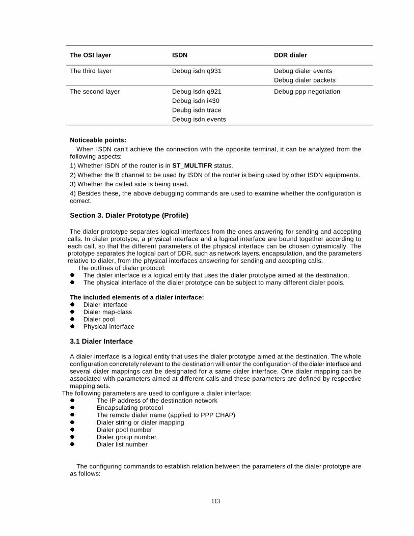
113
The OSI layer ISDN DDR dialer
The third layer Debug isdn q931 Debug dialer events
Debug dialer packets
The second layer Debug isdn q921
Debug isdn i430
Deubg isdn trace
Debug isdn events
Debug ppp negotiation
Noticeable points: When ISDN can’t achieve the connection with the opposite terminal, it can be analyzed from the
following aspects: 1) Whether ISDN of the router is in ST_MULTIFR status.
2) Whether the B channel to be used by ISDN of the router is being used by other ISDN equipments. 3) Whether the called side is being used.
4) Besides these, the above debugging commands are used to examine whether the configuration is correct. Section 3. Dialer Prototype (Profile)
The dialer prototype separates logical interfaces from the ones answering for sending and accepting
calls. In dialer prototype, a physical interface and a logical interface are bound together according to each call, so that the different parameters of the physical interface can be chosen dynamically. The prototype separates the logical part of DDR, such as network layers, encapsulation, and the parameters relative to dialer, from the physical interfaces answering for sending and accepting calls.
The outlines of dialer protocol: z The dialer interface is a logical entity that uses the dialer prototype aimed at the destination. z The physical interface of the dialer prototype can be subject to many different dialer pools. The included elements of a dialer interface: z Dialer interface z Dialer map-class z Dialer pool z Physical interface 3.1 Dialer Interface A dialer interface is a logical entity that uses the dialer prototype aimed at the destination. The whole configuration concretely relevant to the destination will enter the configuration of the dialer interface and several dialer mappings can be designated for a same dialer interface. One dialer mapping can be associated with parameters aimed at different calls and these parameters are defined by respective mapping sets.
The following parameters are used to configure a dialer interface: z The IP address of the destination network z Encapsulating protocol z The remote dialer name (applied to PPP CHAP) z Dialer string or dialer mapping z Dialer pool number z Dialer group number z Dialer list number
The configuring commands to establish relation between the parameters of the dialer prototype are
as follows:
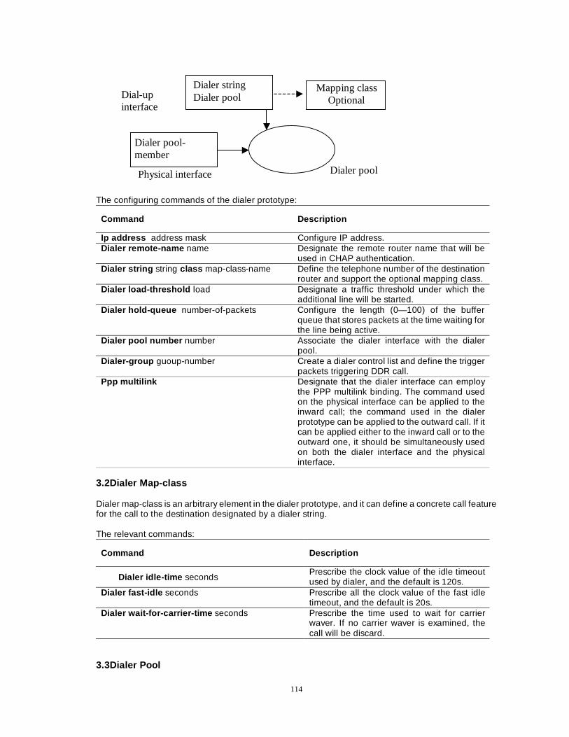
114
The configuring commands of the dialer prototype:
Command Description
Ip address address mask Configure IP address. Dialer remote-name name Designate the remote router name that will be
used in CHAP authentication. Dialer string string class map-class-name Define the telephone number of the destination
router and support the optional mapping class. Dialer load-threshold load Designate a traffic threshold under which the
additional line will be started. Dialer hold-queue number-of-packets Configure the length (0—100) of the buffer
queue that stores packets at the time waiting for the line being active.
Dialer pool number number Associate the dialer interface with the dialer pool.
Dialer-group guoup-number Create a dialer control list and define the trigger packets triggering DDR call.
Ppp multilink Designate that the dialer interface can employ the PPP multilink binding. The command used on the physical interface can be applied to the inward call; the command used in the dialer prototype can be applied to the outward call. If it can be applied either to the inward call or to the outward one, it should be simultaneously used on both the dialer interface and the physical interface.
3.2Dialer Map-class Dialer map-class is an arbitrary element in the dialer prototype, and it can define a concrete call feature for the call to the destination designated by a dialer string. The relevant commands:
Command Description
Dialer idle-time seconds Prescribe the clock value of the idle timeout used by dialer, and the default is 120s.
Dialer fast-idle seconds Prescribe all the clock value of the fast idle timeout, and the default is 20s.
Dialer wait-for-carrier-time seconds Prescribe the time used to wait for carrier waver. If no carrier waver is examined, the call will be discard.
3.3Dialer Pool
Dial-up interface
Dialer string Dialer pool
Mapping class Optional
Physical interface
Dialer pool-member
Dialer pool
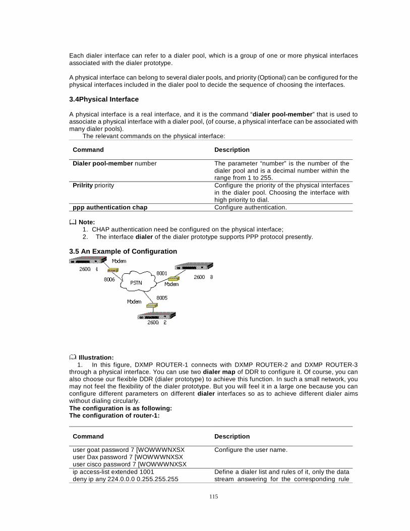
115
Each dialer interface can refer to a dialer pool, which is a group of one or more physical interfaces associated with the dialer prototype. A physical interface can belong to several dialer pools, and priority (Optional) can be configured for the physical interfaces included in the dialer pool to decide the sequence of choosing the interfaces. 3.4Physical Interface A physical interface is a real interface, and it is the command “dialer pool-member ” that is used to associate a physical interface with a dialer pool, (of course, a physical interface can be associated with many dialer pools).
The relevant commands on the physical interface:
Command Description
Dialer pool-member number The parameter “number” is the number of the dialer pool and is a decimal number within the range from 1 to 255.
Prilrity priority Configure the priority of the physical interfaces in the dialer pool. Choosing the interface with high priority to dial.
ppp authentication chap Configure authentication. Note:
1. CHAP authentication need be configured on the physical interface; 2. The interface dialer of the dialer prototype supports PPP protocol presently.
3.5 An Example of Configuration
Illustration:
1. In this figure, DXMP ROUTER-1 connects with DXMP ROUTER-2 and DXMP ROUTER-3 through a physical interface. You can use two dialer map of DDR to configure it. Of course, you can also choose our flexible DDR (dialer prototype) to achieve this function. In such a small network, you may not feel the flexibility of the dialer prototype. But you will feel it in a large one because you can configure different parameters on different dialer interfaces so as to achieve different dialer aims without dialing circularly. The configuration is as following: The configuration of router-1:
Command Description
user goat password 7 [WOWWWNXSX user Dax password 7 [WOWWWNXSX user cisco password 7 [WOWWWNXSX
Configure the user name.
ip access-list extended 1001 deny ip any 224.0.0.0 0.255.255.255
Define a dialer list and rules of it, only the data stream answering for the corresponding rule
116
permit ip any any exit dialer-list 1 protocol ip list 1001
can dial.
interface dialer1 ip address 10.0.0.2 255.0.0.0 dialer remote-name Dax dialer pool 1 dialer-group 1 encapsulation ppp dialer string 8005 exit
Define a dialer interface: the remote-end authentication name is Dax; the dialer pool is 1, and the dialed telephone number of the opposite end is 8005.
interface dialer2 ip address 20.0.0.2 255.0.0.0 dialer remote-name cisco dialer pool 2 dialer-group 1 encapsulation ppp dialer string 8001 exit
Define a dialer interface: the remote-end authentication name is cisco ; the dialer pool is 2, and the dialed telephone number of the opposite end is 8001.
interface serial3 physical-layer async speed 115200 databits 8 stopbits 1 parity none flow-control none dialer pool-member 1 dialer pool-member 2 ecapsulation ppp ppp authentication chap ppp chap hostname goat modem outer exit
Define a physical interface that is associated with two dialer pools. The parameters of dialer pool 1 or 2 can be called, namely calling the parameters of dialer1 port or dialer2 port that are associated with the dialer pools.
The configuration of DXMP ROUTER-2 and DXMP ROUTER-3:
DXMP ROUTER-2 DXMP ROUTER-3
user goat password 7 [WOWWWNXSX ip access-list extended 1001 deny ip any 224.0.0.0 0.255.255.255 permit ip any any exit dialer-list 1 protocol ip list 1001 Define a dialer interface interface dialer1 ip address 10.0.0.1 255.0.0.0 dialer remote-name goat dialer pool 1 dialer-group 1 encapsulation ppp dialer string 8006 exit Associating the physical interface with the dialer interface interface serial3 physical-layer async
user goat password 7 [WOWWWNXSX ip access-list extended 1001 deny ip any 224.0.0.0 0.255.255.255 permit ip any any exit dialer-list 1 protocol ip list 1001 Define a dialer interface. interface dialer1 ip address 20.0.0.1 255.0.0.0 dialer remote-name goat dialer pool 1 dialer-group 1 encapsulation ppp dialer string 8006 exit Associating the physical interface with the dialer interface interface serial3 physical-layer async
117
speed 115200 databits 8 stopbits 1 parity none flow-control none dialer pool-member 1 encapsulation ppp ppp authentication chap ppp chap hostname Dax modem outer exit
speed 115200 databits 8 stopbits 1 parity none flow-control none dialer pool-member 1 encapsulation ppp ppp authentication chap ppp chap hostname cisco modem outer exit
Note:
1. In a large dialer network, you can use the dialer prototype to configure many dialer interfaces (dialer interface).
2. The ISDN network also supports the dialer prototype, and it can employ PPP multilink to bind many ISDN interfaces.
118
Chapter 7 Routing Configuration
This chapter mainly introduces routing mechanism and how to apply many kinds of mainstream routing protocols, such as Routing Information Protocol (RIP), Enhanced Interior Gateway Routing Protocol (EIGRP), Open Shortest Path first (OSPT), to configure DXMP ROUTER router to achieve the network interconnection. The main contents of this chapter: z Introduction of routing z Configuring static route/default route z Configuring RIP dynamic route z Configuring OSPF dynamic route z Configuring EIGRP static route z Configuring ODR route z Load balance
Section 1 Brief Introduction of Routing
Internet protocol is a kind of network protocol being capable of routing, in which a router executes the route addressing function. Each router has a routing table, which is the key to transmit packets. A routing table is created manually by network managers or created dynamically through exchanging route message with other routers. A routing table includes network address, network mask, routing metrics of path, the used interfaces and the IP address of the next routers in the path toward the destination (if the next station is needed). It is this table that the router searches to determine a best path to reach the destination, and then transmit packets along the network path.
DXMP ROUTER router supports many kinds of routing methods, which will be introduced one by one in the following sections: the configuration and usage method of dynamic route/default route, RIPv1/v2 dynamic route, OSPF dynamic route, and homo-EIGRP dynamic route.
Section 2 Configuring Static Route/Default Route
The static route is the route defined by user, and it can enable the transmission between the source and the destination to adopt the path designated by the user.
This section describes how to configure the static route protocol of Dax-Maipu to interconnect networks.
The main contents of this section are as follows:
z Configuring the static route z Configuring the dynamic route
2.1 CONFIGURING STATIC ROUTE
The configuration of the static route mainly includes:
a. Adding/deleting configuration of static route
b. The configuration of the static route administrative distance
The detailed configuring commands are as follows:
A. The relevant commands to configure static route
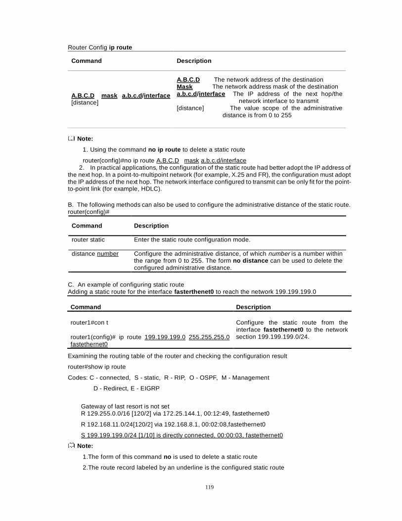
119
Router Config ip route
Command Description
A.B.C.D mask a.b.c.d /interface [distance]
A.B.C.D The network address of the destination Mask The network address mask of the destination a.b.c.d /interface The IP address of the next hop/the
network interface to transmit [distance] The value scope of the administrative
distance is from 0 to 255
Note:
1. Using the command no ip route to delete a static route
router(config)#no ip route A.B.C.D mask a.b.c.d/interface 2. In practical applications, the configuration of the static route had better adopt the IP address of
the next hop. In a point-to-multipoint network (for example, X.25 and FR), the configuration must adopt the IP address of the next hop. The network interface configured to transmit can be only fit for the point-to-point link (for example, HDLC).
B. The following methods can also be used to configure the administrative distance of the static route. router(config)#
Command Description
router static Enter the static route configuration mode.
distance number Configure the administrative distance, of which number is a number within the range from 0 to 255. The form no distance can be used to delete the configured administrative distance.
C. An example of configuring static route Adding a static route for the interface fasterthenet0 to reach the network 199.199.199.0
Command Description
router1#con t
router1(config)# ip route 199.199.199.0 255.255.255.0 fastethernet0
Configure the static route from the interface fastethernet0 to the network section 199.199.199.0/24.
Examining the routing table of the router and checking the configuration result
router#show ip route
Codes: C - connected, S - static, R - RIP, O - OSPF, M - Management
D - Redirect, E - EIGRP
Gateway of last resort is not set R 129.255.0.0/16 [120/2] via 172.25.144.1, 00:12:49, fastethernet0
R 192.168.11.0/24[120/2] via 192.168.8.1, 00:02:08,fastethernet0
S 199.199.199.0/24 [1/10] is directly connected, 00:00:03, fastethernet0
Note:
1.The form of this command no is used to delete a static route
2.The route record labeled by an underline is the configured static route
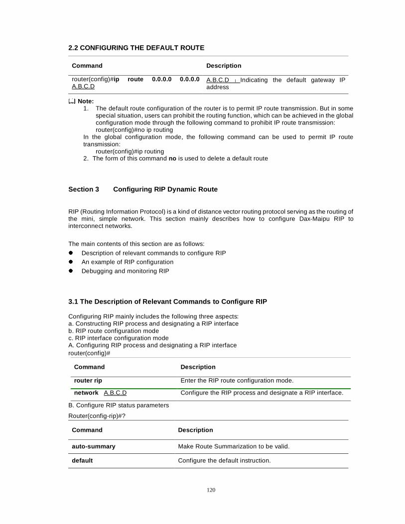
120
2.2 CONFIGURING THE DEFAULT ROUTE
Command Description
router(config)#ip route 0.0.0.0 0.0.0.0 A.B.C.D
A.B.C.D ÖIndicating the default gateway IP address
Note: 1. The default route configuration of the router is to permit IP route transmission. But in some
special situation, users can prohibit the routing function, which can be achieved in the global configuration mode through the following command to prohibit IP route transmission: router(config)#no ip routing
In the global configuration mode, the following command can be used to permit IP route transmission:
router(config)#ip routing 2. The form of this command no is used to delete a default route
Section 3 Configuring RIP Dynamic Route
RIP (Routing Information Protocol) is a kind of distance vector routing protocol serving as the routing of the mini, simple network. This section mainly describes how to configure Dax-Maipu RIP to interconnect networks.
The main contents of this section are as follows:
z Description of relevant commands to configure RIP z An example of RIP configuration
z Debugging and monitoring RIP
3.1 The Description of Relevant Commands to Configure RIP Configuring RIP mainly includes the following three aspects: a. Constructing RIP process and designating a RIP interface b. RIP route configuration mode c. RIP interface configuration mode A. Configuring RIP process and designating a RIP interface router(config)#
Command Description
router rip Enter the RIP route configuration mode.
network A.B.C.D Configure the RIP process and designate a RIP interface.
B. Configure RIP status parameters
Router(config-rip)#?
Command Description
auto-summary Make Route Summarization to be valid.
default Configure the default instruction.
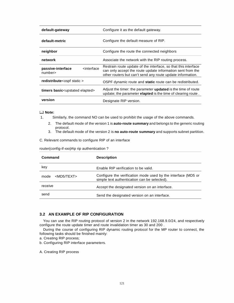
121
default-gateway Configure it as the default gateway.
default-metric Configure the default measure of RIP.
neighbor Configure the route the connected neighbors
network Associate the network with the RIP routing process.
passive-interface <interface number>
Restrain route update of the interface, so that this interface can only accept the route update information sent from the other routers but can’t send any route update information.
redistribute <ospf static > OSPF dynamic route and static route can be redistributed.
timers basic <upstated elapted> Adjust the timer: the parameter updated is the time of route update; the parameter elapted is the time of clearing route .
version Designate RIP version.
Note: 1. Similarly, the command NO can be used to prohibit the usage of the above commands.
2. The default mode of the version 1 is auto-route summary and belongs to the generic routing protocol.
3. The default mode of the version 2 is no auto-route summary and supports subnet partition.
C. Relevant commands to configure RIP of an interface
router(config-if-xxx)#ip rip authentication ?
Command Description
key Enable RIP verification to be valid.
mode <MD5/TEXT> Configure the verification mode used by the interface (MD5 or simple text authentication can be selected).
receive Accept the designated version on an interface.
send Send the designated version on an interface.
3.2 AN EXAMPLE OF RIP CONFIGURATION
You can use the RIP routing protocol of version 2 in the network 192.168.9.0/24, and respectively configure the route update timer and route invalidation timer as 30 and 200 .
During the course of configuring RIP dynamic routing protocol for the MP router to connect, the following tasks should be finished mainly: a. Creating RIP process; b. Configuring RIP interface parameters.
A. Creating RIP process
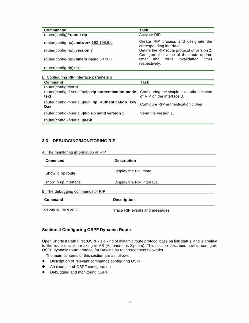
122
B. Configuring RIP interface parameters
Command Task router(config)#int s0 router(config-if-serial0)#ip rip authentication mode text
Configuring the simple text authentication of RIP on the interface 0.
router(config-if-serial0)#ip rip authentication key Dax
Configure RIP authentication cipher.
router(config-if-serial0)#ip rip send version 1 Send the version 1.
router(confgi-if-serial0)#exit
3.3 DEBUGGING/MONITORING RIP
A. The monitoring information of RIP
Command Description
Show ip rip route
Display the RIP route.
show ip rip interface Display the RIP interface.
B. The debugging commands of RIP
Command Description
debug ip rip event Trace RIP events and messages.
Section 4 Configuring OSPF Dynamic Route
Open Shortest Path First (OSPF) is a kind of dynamic route protocol base on link status, and is applied to the route decision-making in AS (Autonomous System). This section describes how to configure OSPF dynamic route protocol for Dax-Maipu to interconnect networks.
The main contents of this section are as follows:
z Description of relevant commands configuring OSPF
z An example of OSPF configuration z Debugging and monitoring OSPF
Commmand Task router(config)#router rip Activate RIP.
router(config-rip)#network 192.168.9.0 Create RIP process and designate the corresponding interface.
router(config-rip)#version 2 Define the RIP route protocol of version 2.
router(config-rip)#timers basic 30 200 Configure the value of the route update timer and route invalidation timer respectively.
router(config-rip)#exit
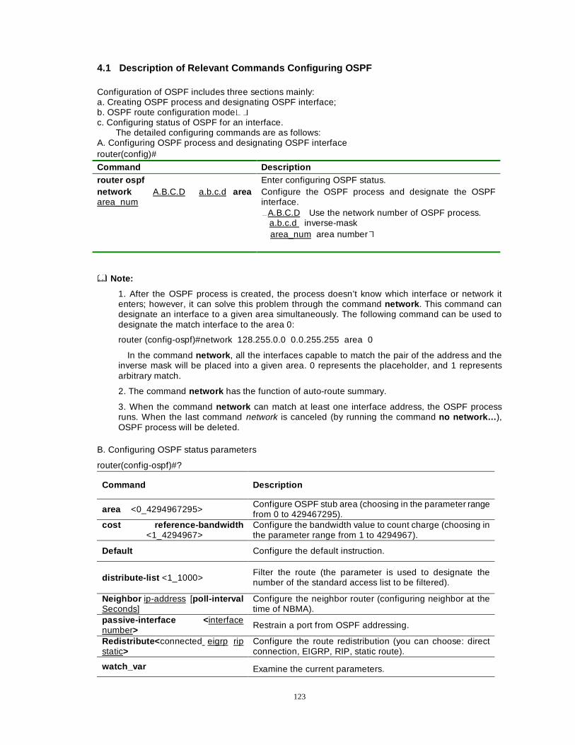
123
4.1 Description of Relevant Commands Configuring OSPF Configuration of OSPF includes three sections mainly: a. Creating OSPF process and designating OSPF interface; b. OSPF route configuration mode�� c. Configuring status of OSPF for an interface.
The detailed configuring commands are as follows: A. Configuring OSPF process and designating OSPF interface router(config)#
Command Description
router ospf Enter configuring OSPF status. network A.B.C.D a.b.c.d area area_num
Configure the OSPF process and designate the OSPF interface. �A.B.C.D Use the network number of OSPF process.
a.b.c.d inverse-mask area_num area number�
Note:
1. After the OSPF process is created, the process doesn’t know which interface or network it enters; however, it can solve this problem through the command network . This command can designate an interface to a given area simultaneously. The following command can be used to designate the match interface to the area 0:
router (config-ospf)#network 128.255.0.0 0.0.255.255 area 0
In the command network , all the interfaces capable to match the pair of the address and the inverse mask will be placed into a given area. 0 represents the placeholder, and 1 represents arbitrary match.
2. The command network has the function of auto-route summary.
3. When the command network can match at least one interface address, the OSPF process runs. When the last command network is canceled (by running the command no network… ), OSPF process will be deleted.
B. Configuring OSPF status parameters
router(config-ospf)#?
Command Description
area <0_4294967295> Configure OSPF stub area (choosing in the parameter range from 0 to 429467295).
cost reference-bandwidth <1_4294967>
Configure the bandwidth value to count charge (choosing in the parameter range from 1 to 4294967).
Default Configure the default instruction.
distribute-list <1_1000> Filter the route (the parameter is used to designate the number of the standard access list to be filtered).
Neighbor ip-address [poll-interval Seconds]
Configure the neighbor router (configuring neighbor at the time of NBMA).
passive-interface < interface number> Restrain a port from OSPF addressing.
Redistribute< connected eigrp rip static>
Configure the route redistribution (you can choose: direct connection, EIGRP, RIP, static route).
watch_var Examine the current parameters.
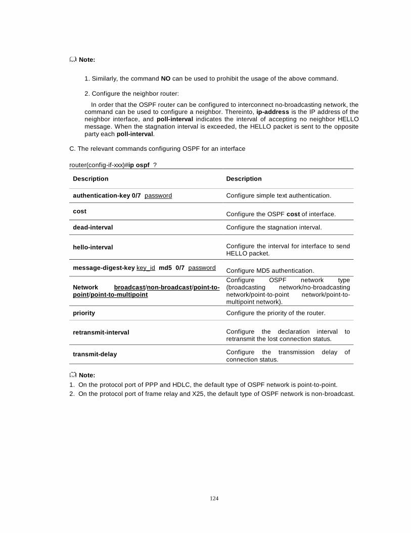
124
Note:
1. Similarly, the command NO can be used to prohibit the usage of the above command.
2. Configure the neighbor router:
In order that the OSPF router can be configured to interconnect no-broadcasting network, the command can be used to configure a neighbor. Thereinto, ip-address is the IP address of the neighbor interface, and poll-interval indicates the interval of accepting no neighbor HELLO message. When the stagnation interval is exceeded, the HELLO packet is sent to the opposite party each poll-interval .
C. The relevant commands configuring OSPF for an interface router(config-if-xxx)#ip ospf ?
Description Description
authentication-key 0/7 password Configure simple text authentication.
cost Configure the OSPF cost of interface.
dead-interval Configure the stagnation interval.
hello-interval Configure the interval for interface to send HELLO packet.
message-digest-key key_id md5 0/7 password Configure MD5 authentication.
Network broadcast /non-broadcast /point-to-point /point-to-multipoint
Configure OSPF network type (broadcasting network/no-broadcasting network/point-to-point network/point-to-multipoint network).
priority Configure the priority of the router.
retransmit-interval Configure the declaration interval to retransmit the lost connection status.
transmit-delay Configure the transmission delay of connection status.
Note:
1. On the protocol port of PPP and HDLC, the default type of OSPF network is point-to-point. 2. On the protocol port of frame relay and X25, the default type of OSPF network is non-broadcast.
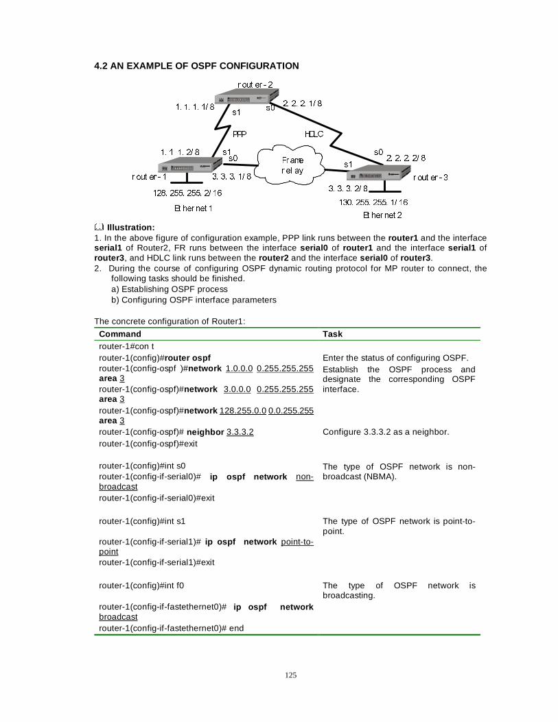
125
4.2 AN EXAMPLE OF OSPF CONFIGURATION
)UDPH
U HO D\
333 +'/&
�� �� �� �� �
�� �� �� �� �
U RXW HU � � U RXW HU � �
U RXW HU � �
�� �� �� �� �
�� �� �� �� �
�� �� �� �� �
�� �� �� �� ����� ���� ���� �� ��
���� ���� ���� �� ��(W KHU QHW �
(W KHU QHW �
V�
V�V�
V�
V�V�
Illustration: 1. In the above figure of configuration example, PPP link runs between the router1 and the interface serial1 of Router2, FR runs between the interface serial0 of router1 and the interface serial1 of router3 , and HDLC link runs between the router2 and the interface serial0 of router3 . 2. During the course of configuring OSPF dynamic routing protocol for MP router to connect, the
following tasks should be finished. a) Establishing OSPF process b) Configuring OSPF interface parameters The concrete configuration of Router1:
Command Task router-1#con t router-1(config)#router ospf Enter the status of configuring OSPF. router-1(config-ospf )#network 1.0.0.0 0.255.255.255 area 3 router-1(config-ospf)#network 3.0.0.0 0.255.255.255 area 3
Establish the OSPF process and designate the corresponding OSPF interface.
router-1(config-ospf)#network 128.255.0.0 0.0.255.255 area 3
router-1(config-ospf)# neighbor 3.3.3.2 Configure 3.3.3.2 as a neighbor. router-1(config-ospf)#exit router-1(config)#int s0 router-1(config-if-serial0)# ip ospf network non-broadcast
The type of OSPF network is non-broadcast (NBMA).
router-1(config-if-serial0)#exit router-1(config)#int s1 The type of OSPF network is point-to-
point. router-1(config-if-serial1)# ip ospf network point-to-point router-1(config-if-serial1)#exit
router-1(config)#int f0 The type of OSPF network is
broadcasting. router-1(config-if-fastethernet0)# ip ospf network broadcast
router-1(config-if-fastethernet0)# end
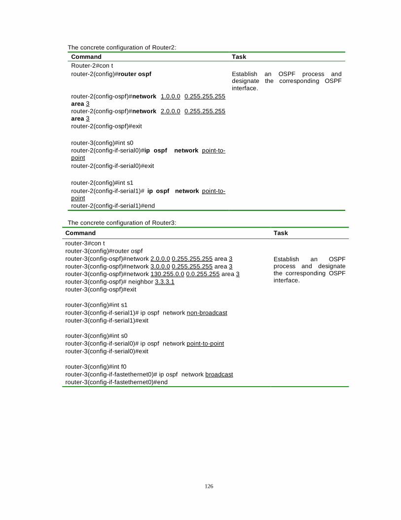
126
The concrete configuration of Router2:
Command Task Router-2#con t router-2(config)#router ospf Establish an OSPF process and
designate the corresponding OSPF interface.
router-2(config-ospf)#network 1.0.0.0 0.255.255.255 area 3 router-2(config-ospf)#network 2.0.0.0 0.255.255.255 area 3 router-2(config-ospf)#exit
router-3(config)#int s0 router-2(config-if-serial0)#ip ospf network point-to-point
router-2(config-if-serial0)#exit router-2(config)#int s1 router-2(config-if-serial1)# ip ospf network point-to-point router-2(config-if-serial1)#end
The concrete configuration of Router3:
Command Task
router-3#con t router-3(config)#router ospf router-3(config-ospf)#network 2.0.0.0 0.255.255.255 area 3 router-3(config-ospf)#network 3.0.0.0 0.255.255.255 area 3 router-3(config-ospf)#network 130.255.0.0 0.0.255.255 area 3 router-3(config-ospf)# neighbor 3.3.3.1 router-3(config-ospf)#exit
Establish an OSPF process and designate the corresponding OSPF interface.
router-3(config)#int s1 router-3(config-if-serial1)# ip ospf network non-broadcast router-3(config-if-serial1)#exit
router-3(config)#int s0 router-3(config-if-serial0)# ip ospf network point-to-point router-3(config-if-serial0)#exit
router-3(config)#int f0 router-3(config-if-fastethernet0)# ip ospf network broadcast router-3(config-if-fastethernet0)#end
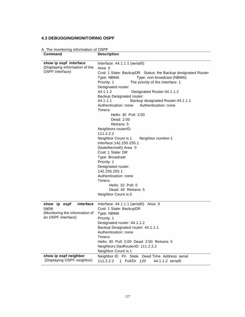
127
4.3 DEBUGGING/MONITORING OSPF
A. The monitoring information of OSPF
Command Description
show ip ospf interface (Displaying information of the OSPF interface)
Interface: 44.1.1.1 (serial0) Area 0 Cost: 1 State: BackupDR Status: the Backup designated Router Type: NBMA Type: non-broadcast (NBMA) Priority: 1 The priority of the interface: 1 Designated router: 44.1.1.2 Designated Router:44.1.1.2 Backup Designated router: 44.1.1.1 Backup designated Router:44.1.1.1 Authentication: none Authentication: none Timers:
Hello: 30 Poll: 2:00 Dead: 2:00 Retrans: 5
Neighbors routerID: 111.2.2.2 Neighbor Count is 1 Neighbor number:1 Interface:142.255.255.1 (fastethernet0) Area 0 Cost: 1 State: DR Type: Broadcast Priority: 1 Designated router: 142.255.255.1 Authentication: none Timers:
Hello: 10 Poll: 0 Dead: 40 Retrans: 5
Neighbor Count is 0
show ip ospf interface name (Monitoring the information of an OSPF interface)
Interface: 44.1.1.1 (serial0) Area 0 Cost: 1 State: BackupDR Type: NBMA Priority: 1 Designated router: 44.1.1.2 Backup Designated router: 44.1.1.1 Authentication: none Timers: Hello: 30 Poll: 2:00 Dead: 2:00 Retrans: 5 Neighbors DaxRouterID: 111.2.2.2 Neighbor Count is 1
show ip ospf neighbor (Displaying OSPF neighbor)
Neighbor ID Pri State Dead Time Address serial 111.2.2.2 1 Full/Dr 120 44.1.1.2 serial0
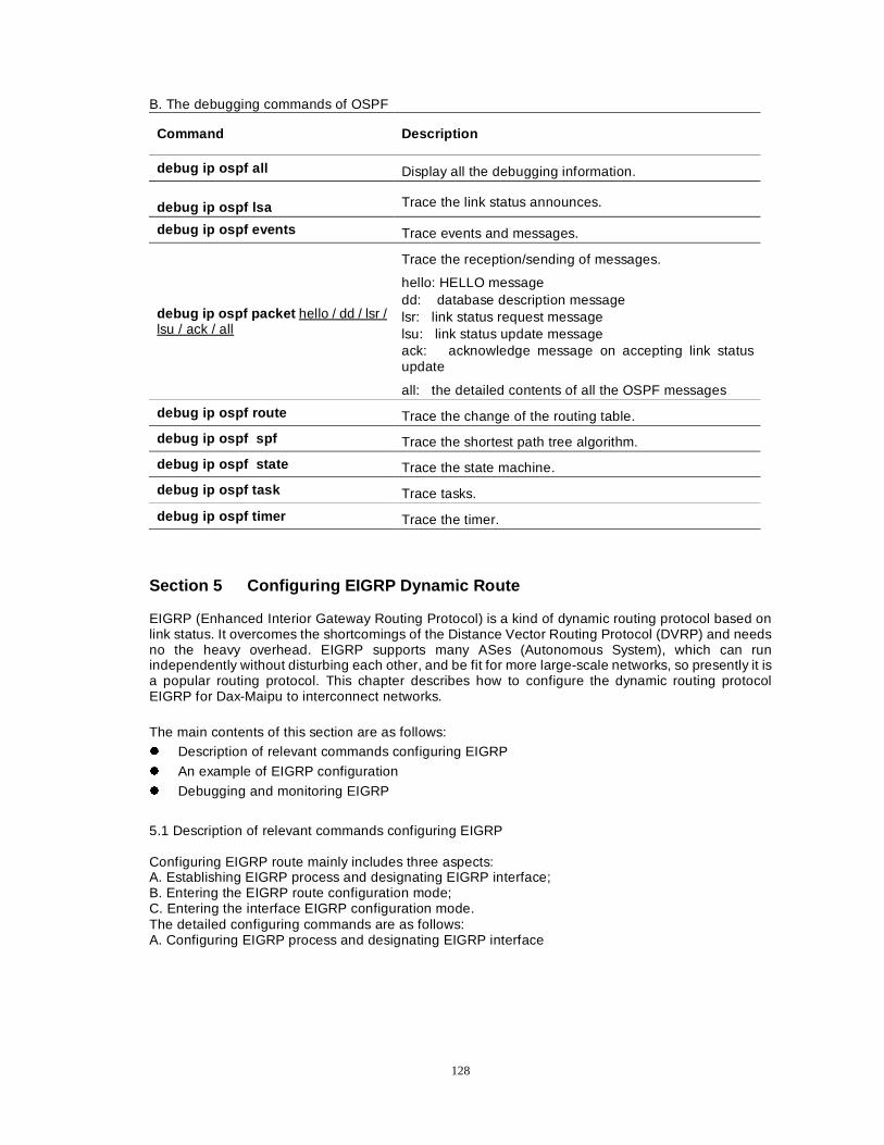
128
B. The debugging commands of OSPF
Command Description
debug ip ospf all Display all the debugging information.
debug ip ospf lsa Trace the link status announces.
debug ip ospf events Trace events and messages.
debug ip ospf packet hello / dd / lsr / lsu / ack / all
Trace the reception/sending of messages.
hello: HELLO message dd: database description message lsr: link status request message lsu: link status update message ack: acknowledge message on accepting link status update
all: the detailed contents of all the OSPF messages
debug ip ospf route Trace the change of the routing table.
debug ip ospf spf Trace the shortest path tree algorithm.
debug ip ospf state Trace the state machine.
debug ip ospf task Trace tasks.
debug ip ospf timer Trace the timer.
Section 5 Configuring EIGRP Dynamic Route
EIGRP (Enhanced Interior Gateway Routing Protocol) is a kind of dynamic routing protocol based on link status. It overcomes the shortcomings of the Distance Vector Routing Protocol (DVRP) and needs no the heavy overhead. EIGRP supports many ASes (Autonomous System), which can run independently without disturbing each other, and be fit for more large-scale networks, so presently it is a popular routing protocol. This chapter describes how to configure the dynamic routing protocol EIGRP for Dax-Maipu to interconnect networks.
The main contents of this section are as follows: z Description of relevant commands configuring EIGRP
z An example of EIGRP configuration
z Debugging and monitoring EIGRP
5.1 Description of relevant commands configuring EIGRP Configuring EIGRP route mainly includes three aspects: A. Establishing EIGRP process and designating EIGRP interface; B. Entering the EIGRP route configuration mode; C. Entering the interface EIGRP configuration mode. The detailed configuring commands are as follows: A. Configuring EIGRP process and designating EIGRP interface
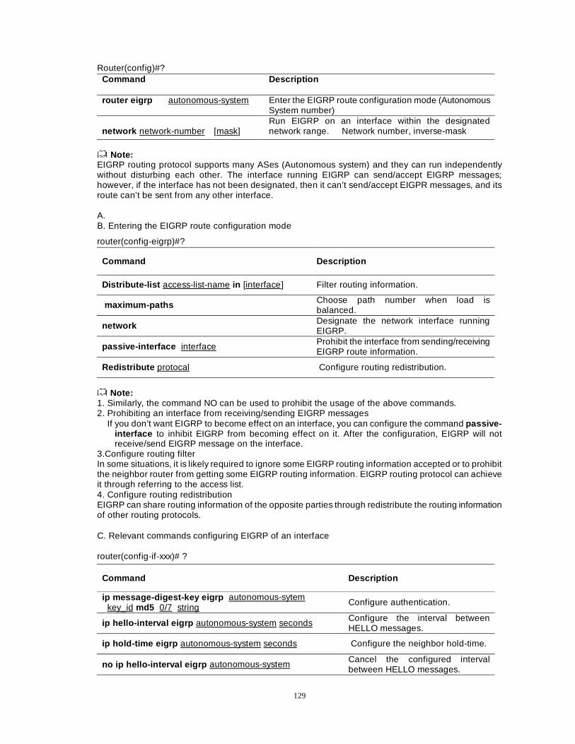
129
Router(config)#? Command Description
router eigrp autonomous-system Enter the EIGRP route configuration mode (Autonomous System number)
network network-number [mask]
Run EIGRP on an interface within the designated network range. Network number, inverse-mask
Note: EIGRP routing protocol supports many ASes (Autonomous system) and they can run independently without disturbing each other. The interface running EIGRP can send/accept EIGRP messages; however, if the interface has not been designated, then it can’t send/accept EIGPR messages, and its route can’t be sent from any other interface. A. B. Entering the EIGRP route configuration mode
router(config-eigrp)#?
Command Description
Distribute-list access-list-name in [interface] Filter routing information.
maximum-paths Choose path number when load is balanced.
network Designate the network interface running EIGRP.
passive-interface interface Prohibit the interface from sending/receiving EIGRP route information.
Redistribute protocal Configure routing redistribution.
Note: 1. Similarly, the command NO can be used to prohibit the usage of the above commands. 2. Prohibiting an interface from receiving/sending EIGRP messages If you don’t want EIGRP to become effect on an interface, you can configure the command passive-
interface to inhibit EIGRP from becoming effect on it. After the configuration, EIGRP will not receive/send EIGRP message on the interface.
3.Configure routing filter In some situations, it is likely required to ignore some EIGRP routing information accepted or to prohibit the neighbor router from getting some EIGRP routing information. EIGRP routing protocol can achieve it through referring to the access list. 4. Configure routing redistribution EIGRP can share routing information of the opposite parties through redistribute the routing information of other routing protocols.
C. Relevant commands configuring EIGRP of an interface
router(config-if-xxx)# ?
Command Description
ip message-digest-key eigrp autonomous-sytem key_id md5 0/7 string Configure authentication.
ip hello-interval eigrp autonomous-system seconds Configure the interval between HELLO messages.
ip hold-time eigrp autonomous-system seconds Configure the neighbor hold-time.
no ip hello-interval eigrp autonomous-system Cancel the configured interval between HELLO messages.
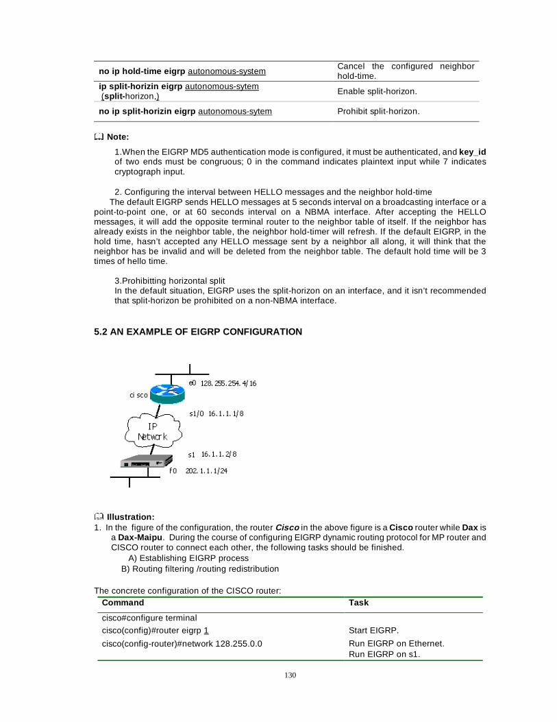
130
no ip hold-time eigrp autonomous-system Cancel the configured neighbor hold-time.
ip split-horizin eigrp autonomous-sytem (split- horizon,) Enable split-horizon.
no ip split-horizin eigrp autonomous-sytem Prohibit split-horizon.
Note:
1.When the EIGRP MD5 authentication mode is configured, it must be authenticated, and key_id of two ends must be congruous; 0 in the command indicates plaintext input while 7 indicates cryptograph input. 2. Configuring the interval between HELLO messages and the neighbor hold-time
The default EIGRP sends HELLO messages at 5 seconds interval on a broadcasting interface or a point-to-point one, or at 60 seconds interval on a NBMA interface. After accepting the HELLO messages, it will add the opposite terminal router to the neighbor table of itself. If the neighbor has already exists in the neighbor table, the neighbor hold-timer will refresh. If the default EIGRP, in the hold time, hasn’t accepted any HELLO message sent by a neighbor all along, it will think that the neighbor has be invalid and will be deleted from the neighbor table. The default hold time will be 3 times of hello time.
3.Prohibitting horizontal split In the default situation, EIGRP uses the split-horizon on an interface, and it isn’t recommended that split-horizon be prohibited on a non-NBMA interface.
5.2 AN EXAMPLE OF EIGRP CONFIGURATION
Illustration: 1. In the figure of the configuration, the router Cisco in the above figure is a Cisco router while Dax is
a Dax-Maipu . During the course of configuring EIGRP dynamic routing protocol for MP router and CISCO router to connect each other, the following tasks should be finished.
A) Establishing EIGRP process B) Routing filtering /routing redistribution
The concrete configuration of the CISCO router: Command Task
cisco#configure terminal
cisco(config)#router eigrp 1 Start EIGRP.
cisco(config-router)#network 128.255.0.0
Run EIGRP on Ethernet. Run EIGRP on s1.
131
cisco(config-router)#network 16.0.0.0 cisco(config-router)#end
The concrete configuration of the Dax-Maipu
Command Task
Dax#configure terminal Dax(config)#router eigrp 1 Start EIGRP. Dax(config-eigrp)#network 202.1.1.0 Dax(config-eigrp)#network 16.0.0.0 Dax(config-eigrp)#end
Run EIGRP on Ethernet. Run EIGRP on s1.
Filtering all routes on the Dax-Maipu
Command Task Dax#configure terminal
Dax(config)#access-list 9 deny any Create an access list (Rules can defined according to requestion).
Dax(config)#router eigrp 1 Dax(config-eigrp)#distribute-list 9 in Apply the access list to EIGRP. Dax(config-eigrp)#end
Redistributing static route
Command Task Dax#configure terminal Dax(config)#router eigrp 1
Dax(config-eigrp)#redistribute static Redistribute static routing into EIGRP.
Dax(config-eigrp)#end
5.3 DEBUGGING/MONITORING EIGRP
A. The monitoring information of EIGRP
Command Description
show ip eigrp interface [interface] Display the interface information of current EIGRP.
show ip eigrp neighbor [autonomous-system / detail / interface]
Display the neighbor information of current EIGRP.
show ip eigrp topology [active / summary / network]
Display the routing information of current EIGRP.
B. Debugging commands of EIGRP
Command Description debug ip eigrp events Display the debug information of EIGRP
events. debug ip eigrp route Display the debug information of EIGRP
route. debug ip eigrp timer Display the EIGRP timer. debug ip eigrp packets [hello / terse ] Display the debug information of EIGRP
messages. debug ip eigrp all Display the debug information of all the
EIGRP.
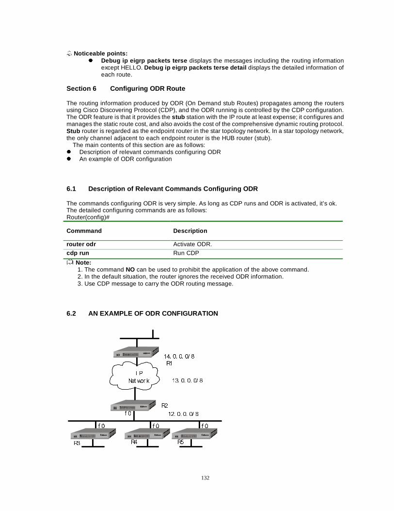
132
� Noticeable points:
z Debug ip eigrp packets terse displays the messages including the routing information except HELLO. Debug ip eigrp packets terse detail displays the detailed information of each route.
Section 6 Configuring ODR Route
The routing information produced by ODR (On Demand stub Routes) propagates among the routers using Cisco Discovering Protocol (CDP), and the ODR running is controlled by the CDP configuration. The ODR feature is that it provides the stub station with the IP route at least expense; it configures and manages the static route cost, and also avoids the cost of the comprehensive dynamic routing protocol. Stub router is regarded as the endpoint router in the star topology network. In a star topology network, the only channel adjacent to each endpoint router is the HUB router (stub).
The main contents of this section are as follows: z Description of relevant commands configuring ODR z An example of ODR configuration
6.1 Description of Relevant Commands Configuring ODR The commands configuring ODR is very simple. As long as CDP runs and ODR is activated, it’s ok. The detailed configuring commands are as follows: Router(config)#
Commmand Description
router odr Activate ODR.
cdp run Run CDP
Note: 1. The command NO can be used to prohibit the application of the above command. 2. In the default situation, the router ignores the received ODR information. 3. Use CDP message to carry the ODR routing message.
6.2 AN EXAMPLE OF ODR CONFIGURATION
5�
5�
5� 5� 5�
��� �� �� �� �I �
I � I � I �
, 3
1HW ZRU N ��� �� �� �� �
��� �� �� �� �
133
Illustration: 1. The router R2 serves as a stub router. It is configured with ODR and EIGRP routing
protocols, and executes CDP. 2. The down-end routers, R3, R4 and R5 run CDP and they are configured with the default
route without the dynamic route. 3. EIGRP redistributes the ODR route on the route R2.
A. The configuration of the Dax-Maipu R2:
Command Task
R2#configure terminal R2(config)#router odr Run ODR. R2(config)#cdp run Run CDP. R2(config)#router eigrp 1 R2(config-eigrp)#netw 13.0.0.0 R2(config-eigrp)#redistribute odr EIGRP redistributes ODR. R2(config-eigrp)#end
B. The configuration of the Dax-Maipu R3 (the configuration of R4 or R5 is the same as that of R3)
Command Task
R3#configure terminal R3(config)#cdp run Run CDP. R3(config)#ip route 0.0.0.0 0.0.0.0 fastethernet0 Configure the default route. R3(config)#end
Section 7 Load Balance Dax-Maipu supports the routing load balance now, namely, if there exist many routes to a destination, the router will add these routes into the route table. When the data is transferred, the data load can be transmitted through this interface link in a certain proportion.
The main contents of this section are as follows: z Description of relevant commands supporting load balance z An example of load balance configuration z Monitoring and debugging load balance
7.1 DESCRIPTION OF RELEVANT COMMANDS SUPPORTING LOAD BALANCE
When data is transferred, it need generally close two caches in order that the data load can pass through the interface link in a certain proportion. The concrete configuring commands are as follows:
A.Router(config)#
Command Description
no ip upper-cache Close the upper cache.
B.Router(config-if-xxx)#
Command Description
no ip route-cache Close the route cache.
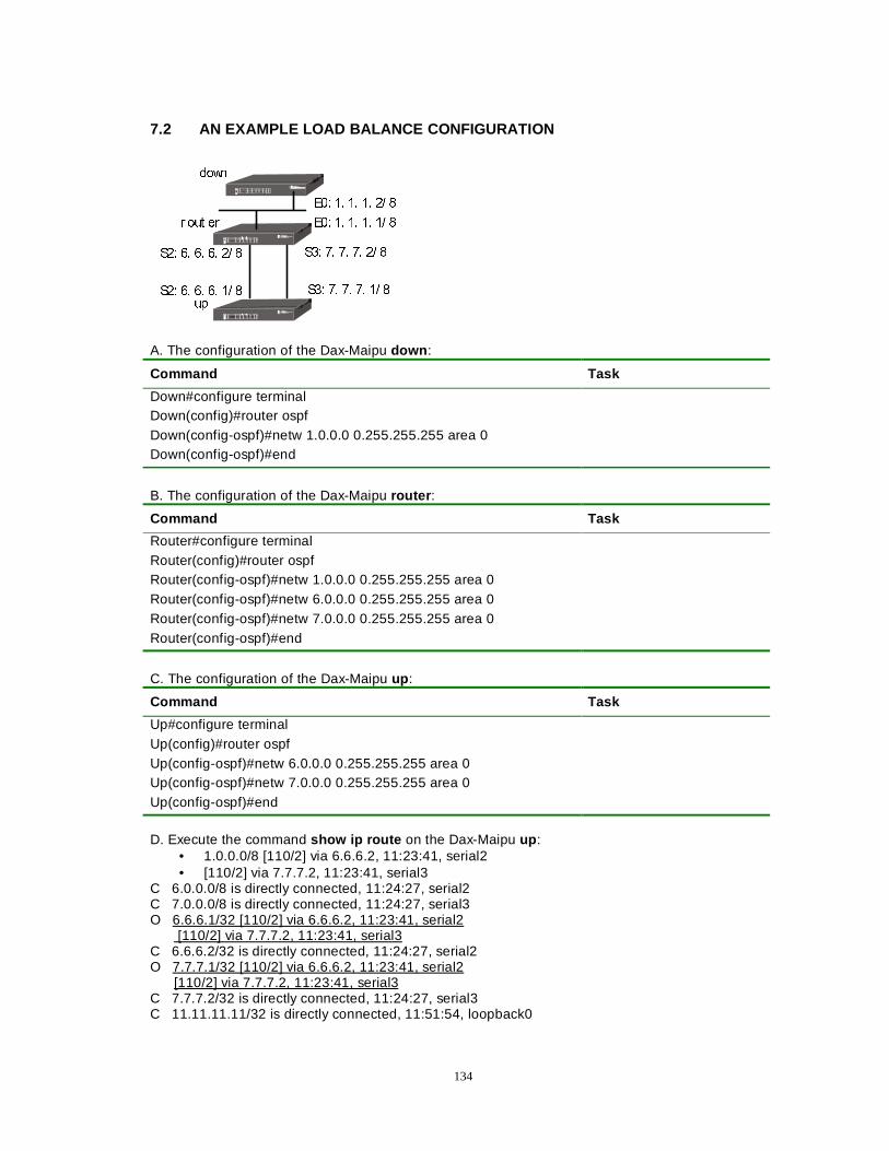
134
7.2 AN EXAMPLE LOAD BALANCE CONFIGURATION
GRZQ
URXW HU
XS
(�� �� �� �� �� �
(�� �� �� �� �� �
6�� �� �� �� �� �
6�� �� �� �� �� �
6�� �� �� �� �� �
6�� �� �� �� �� �
A. The configuration of the Dax-Maipu down :
Command Task
Down#configure terminal Down(config)#router ospf Down(config-ospf)#netw 1.0.0.0 0.255.255.255 area 0 Down(config-ospf)#end
B. The configuration of the Dax-Maipu router :
Command Task
Router#configure terminal Router(config)#router ospf Router(config-ospf)#netw 1.0.0.0 0.255.255.255 area 0 Router(config-ospf)#netw 6.0.0.0 0.255.255.255 area 0 Router(config-ospf)#netw 7.0.0.0 0.255.255.255 area 0 Router(config-ospf)#end
C. The configuration of the Dax-Maipu up :
Command Task
Up#configure terminal Up(config)#router ospf Up(config-ospf)#netw 6.0.0.0 0.255.255.255 area 0 Up(config-ospf)#netw 7.0.0.0 0.255.255.255 area 0 Up(config-ospf)#end
D. Execute the command show ip route on the Dax-Maipu up :
• 1.0.0.0/8 [110/2] via 6.6.6.2, 11:23:41, serial2 • [110/2] via 7.7.7.2, 11:23:41, serial3
C 6.0.0.0/8 is directly connected, 11:24:27, serial2 C 7.0.0.0/8 is directly connected, 11:24:27, serial3 O 6.6.6.1/32 [110/2] via 6.6.6.2, 11:23:41, serial2 [110/2] via 7.7.7.2, 11:23:41, serial3 C 6.6.6.2/32 is directly connected, 11:24:27, serial2 O 7.7.7.1/32 [110/2] via 6.6.6.2, 11:23:41, serial2 [110/2] via 7.7.7.2, 11:23:41, serial3 C 7.7.7.2/32 is directly connected, 11:24:27, serial3 C 11.11.11.11/32 is directly connected, 11:51:54, loopback0
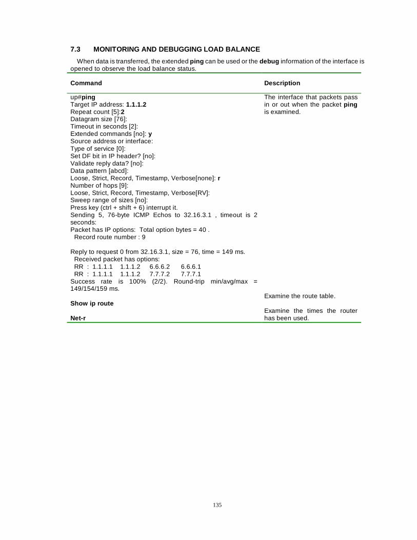
135
7.3 MONITORING AND DEBUGGING LOAD BALANCE
When data is transferred, the extended ping can be used or the debug information of the interface is opened to observe the load balance status.
Command Description
up#ping Target IP address: 1.1.1.2 Repeat count [5]:2 Datagram size [76]: Timeout in seconds [2]: Extended commands [no]: y Source address or interface: Type of service [0]: Set DF bit in IP header? [no]: Validate reply data? [no]: Data pattern [abcd]: Loose, Strict, Record, Timestamp, Verbose[none]: r Number of hops [9]: Loose, Strict, Record, Timestamp, Verbose[RV]: Sweep range of sizes [no]: Press key (ctrl + shift + 6) interrupt it. Sending 5, 76-byte ICMP Echos to 32.16.3.1 , timeout is 2 seconds: Packet has IP options: Total option bytes = 40 . Record route number : 9 Reply to request 0 from 32.16.3.1, size = 76, time = 149 ms. Received packet has options: RR : 1.1.1.1 1.1.1.2 6.6.6.2 6.6.6.1 RR : 1.1.1.1 1.1.1.2 7.7.7.2 7.7.7.1 Success rate is 100% (2/2). Round-trip min/avg/max = 149/154/159 ms.
The interface that packets pass in or out when the packet ping is examined.
Show ip route Net-r
Examine the route table. Examine the times the router has been used.
136
Chapter 8 MPLS Configuration
MPLS (Multiprotocol Label Switching) is a label-based packet forwarding technology, with advantages of both the packet forwarding technology of layer-2 switch and the routing technology of layer-3, simplifying segment-by-segment data forwarding and enhancing the packet forwarding capacity.
The main contents of this chapter are as follows:
zz Brief introduction to MPLS
zz Descriptions of commands to configure MPLS
zz An example of MPLS configuration
8.1 Brief Introduction to MPLS
For the traditional IP packet forwarding, the router in each relay segment of the network analyses the destination IP address independently and executes the network routing algorithm so as to make the independent forwarding decision and determine the next hot for the packet. However, MPLS divides all packets that enter the network into different FECs (Forwarding Equivalence Class) and assigns a label to each FEC, so each packet carries a short label with fixed length. The routers in the network determine how to forward a packet according to its label. In the whole MPLS area, the packet forwarding is operated according to the label, without operating anything to the IP header.
MPLS consists of two sections. One is the label packet forwarding, implementing the forwarding of the received IP packets or label packets. Its main operations include:
1) If the received packet is an IP packet, then search the label forwarding list according to its destination address; if there exists the output label (namely, the next hop supports the label forwarding) of the destination address, then insert this output label into the IP header, subsequently, forward this packet to the next hop.
2) If the received packet is a label packet, then search the label forwarding list according to the input label on the stack top; if it succeeds in finding out the corresponding output label, then replace the input label with the output label, subsequently, forward this packet; if it fails in finding out the corresponding output label, then pop the input label, subsequently, forward this packet in the form of IP packet.
The other section is LDP (Label Distribution Protocol), used to switch the label binding information with the neighbor routers. Through sending Hello packets periodically, LDP finds and maintains a LDP peer. When finding out a new LDP neighbor, LDP creates a TCP connection with it. Then, through this TCP connection, it uses the information switch label that LDP defines to bind the information, create and maintain a label-forwarding list.
8.2 Descriptions of commands to configure MPLS � mpls ip
To enable mpls on the router, you can do nothing but configure the command under the global configuration mode and the interface configuration mode. The form no of this command is used to disable mpls.
mpls ip
no mpls ip
�Command mode�The global configuration mode and the interface configuration mode.
137
Note:
To use mpls , you must simultaneously configure the command mpls ip under both the global configuration mode and the interface configuration mode. Configuring the command mpls ip under the global configuration mode is used to enable mpls , while configuring the command under the interface configuration mode is used to specify which interface to use mpls packet forwarding. You can configure the command mpls ip on multiple interfaces.
If the link layer protocol is PPP, then it needs to configure the command ppp mpls on the interface.
z mpls ldp router-id
When mpls is enabled, you need select a router-id (namely, an IP address) to serve as the ldp ID, which is used to identify a specific LSR label space. The form no of this command is used to reset the default value of route id .
mpls ldp router-id A,B,C,D
no mpls ldp router-id
Syntax Descriptions
A.B.C.D This is an IP address serving as the ldp ID.
Default: When mpls starts, it automatically selects an interface address to serve as router-id.
Command mode:The global configuration mode.
Note:
By default, mpls automatically selects an interface address to serve as router-id when starting. And it can select the address of a loopback interface. Under the situation that no router-id is configured, if the selected interface address that serves as the router-id is changed, all current ldp connections are deleted, and the ldp can update the router-id, subsequently, a new connection is rebuilt.
z mpls ldp label-distribution
This command is used to set the ldp label distribution mode. The form no of this command is used to reset the default setting of the label distribution mode.
mpls ldp label-distribution <dod/du>
no mpls ldp label-distribution
Syntax Descriptions
dod/du Label distribution is on demand or unsolicited for downstream.
Default-The DU (downstream unsolicited) label distribution mode.
Command mode-The interface configuration mode.
Note:
When using the downstream-unsolicited label distribution mode, for a specific FEC, an LSR (label switched router) can assign and distribute a label immediately without getting a label request message from the upstream; however, when using the downstream-on-demand label distribution mode, for a specific FEC, only after receiving the upstream label request message from the upstream can an LSR (label switched router) assign and distribute a label.
This command is configured under the interface mode, and different label distribution modes can be configured for different interfaces.
z mpls ldp label-control
This command is used to configure the ldp label control mode. The form no of this command is used to reset the default setting of the ldp label control mode.
138
mpls ldp label-control <independent/ordered>
no mpls ldp label-control
Syntax Descriptions
independent/ordered The independent control mode or the ordered control mode.
Default-The independent control mode.
Command mode-The global configuration mode.
Note:
When using the independent label control mode, each LSR can announce the label mapping to the LSR (label switch router) that connects with it at any time; however, when using the ordered control mode, only after the LSR receives the FEC label mapping message of the specific FEC net hop or when the LSR is the LSP out-bound node, can the LSR send label mapping messages to the upstream.
z mpls ldp label-retention
This command is used to set the ldp label retention mode. The form no of this command is used to reset the default setting of the ldp label hold mode.
mpls ldp label-retention <conservative/liberal>
no mpls ldp label-control
Syntax Descriptions
conservative/liberal The conservative hold mode or the liberal retention mode.
Default:The liberal retention mode.
Command mode:The global configuration mode.
Note:
For a specific FEC, suppose that the upstream has received the label binding that comes from the downstream, then, when the downstream router is no longer the next hop of this FEC, if the upstream still preserves this binding, the mode used by the upstream is called the liberal label retention mode; if the upstream discards this binding, then the mode used by the upstream is called the conservative label retention mode.
There are various combinations between three label assignment parameters (label distribution mode, label control mode and label retention mode). However, the default parameters are downstream-unsolicited distribution, independent control and liberal retention.
z mpls ldp hello-interval
This command is used to set the interval (by second) for LSR to send a Hello message periodically. The form no of this command is used to reset the default setting of interval of the Hello message.
mpls ldp hello-interval <1-60>
no mpls hello-interval
Syntax Descriptions
1-60 The interval to send a Hello message.
�Default�5 seconds.
�Command mode�The interface configuration mode.
139
Note:
Through sending the Hello packet periodically, LSR finds or maintains a Hello neighbor.
z mpls ldp hello-hold-interval
This command is used to set the hold time of ldp hello. The hold time specifies the maximum hold time (by second) for the LSR to keep the previous Hello message before sending the next Hello message to its peer. LSRs can, through respectively putting forward its own Hello hold time firstly, negotiate the Hello hold time with each other and then adopt the minimum value of them. The form no of this command is used to reset the default value of the Hello hold time.
mpls ldp hello-hold-interval <1-60>
no mpls ldp hello-hold-interval
Syntax Descriptions
1-60 Hello hold time.
Default-15 seconds.
Command mode-The interface configuration mode.
Note:
LSR maintains a Hello hold timer for each Hello neighbor peer. When an LSR receives a Hello message from a specific Hello neighbor, the corresponding Hello hold timer will be restarted. If the LSR hasn’t still received the next Hello message from the specific Hello neighbor when the Hello hold timer expires, then LSR deletes this Hello neighbor, and sends the corresponding announcement message; subsequently, closes the TCP connection and ends the LDP session.
Hello hold time being 0 indicates the default value. For a link Hello message (connecting with the neighbor directly), the default value is 15s; while for a destination Hello message (not connecting with the neighbor directly), the default value is 45s.
z mpls ldp keepalive-interval
This command is used to set the interval (by second) for LSR to send a Keepalive message periodically. The form no of this command is used to reset the default setting of the Keepalive message.
mpls ldp keepalive-interval <1-60>
no mpls keepalive-interval
Syntax Descriptions
1-60 The interval for LSR to send a Keepalive message periodically.
Default-15 seconds.
Command mode-The interface configuration mode.
Note:
An LSR must ensure that the LDP peer can receive at least one LDP message (any LDP message is effective) in the keepalive-interval. But if there is no other LDP message for LSR to send, then LSR must send a session hold message.
z mpls ldp keepalive-hold-interval
This command is used to set the ldp session hold interval. LSRs can, through putting forward its own session hold interval respectively, negotiate the session hold interval with each other, and then adopts the minimum value of them. The form no of this command is used to reset the default value of the session hold interval.
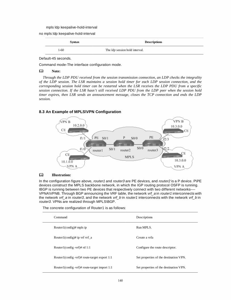
140
mpls ldp keepalive-hold-interval
no mpls ldp keepalive-hold-interval
Syntax Descriptions
1-60 The ldp session hold interval.
Default-45 seconds.
Command mode-The interface configuration mode.
Note:
Through the LDP PDU received from the session transmission connection, an LDP checks the integrality of the LDP session. The LSR maintains a session hold timer for each LDP session connection, and the corresponding session hold timer can be restarted when the LSR receives the LDP PDU from a specific session connection. If the LSR hasn’t still received LDP PDU from the LDP peer when the session hold timer expires, then LSR sends an announcement message, closes the TCP connection and ends the LDP session.
8.3 An Example of MPLS\VPN Configuration
Illustration:
In the configuration figure above, router1 and router3 are PE devices, and router2 is a P device. P\PE devices construct the MPLS backbone network, in which the IGP routing protocol OSFP is running. IBGP is running between two PE devices that respectively connect with two different networks----VPNA\VPNB. Through BGP announcing the VRF table, the network vrf_a in router1 interconnects with the network vrf_a in router3, and the network vrf_b in router1 interconnects with the network vrf_b in router3. VPNs are realized through MPLS\BGP.
The concrete configuration of Router1 is as follows:
Command Descriptions
Router1(config)# mpls ip Run MPLS.
Router1(config)# ip vrf vrf_a Create a vrfa
Router1(config -vrf)# rd 1:1 Configure the route descriptor.
Router1(config -vrf)# route-target export 1:1 Set properties of the destination VPN.
Router1(config -vrf)# route-target import 1:1 Set properties of the destination VPN.
141
Router1(config -vrf)#exit
Router1(config)# ip vrf vrf_b Create a vrfb.
Router1(config -vrf)# rd 2:2 Configure the route descriptor.
Router1(config -vrf)# route-target export 2:2 Set properties of the destination VPN.
Router1(config -vrf)# route-target import 2:2 Set properties of the destination VPN.
Router1(config -vrf)#exit
Router1(config)# interface loopback0 Configure the loopback address with 12.12.12.12.
Router1 (config-if-loopback0)# ip address 12.12.12.12 255.255.255.255
Router1 (config-if-loopback0)# interface fastethernet 1/0
Router1 (config-if-fastethernet1/0)# ip vrf forwarding vrf_a
Add the interface into the vrfa.
Router1 (config-if-fastethernet1/0)# ip address 10.1.1.1 255.255.0.0
Configure the IP address.
Router1 (config-if- fastethernet1/0)# interface fastethernet 1/1
Router1 (config-if-fastethernet1/1)# ip vrf forwarding vrf_b
Add the interface into the vrfb.
Router1 (config-if-fastethernet1/1)# ip address 10.2.1.1 255.255.0.0
Configure the IP address.
Router1 (config-if-fastethernet1/1)#interface serial0/1
Router1 (config -if-serial0/1)# encapsulation ppp Encapsulate PPP.
Router1 (config -if-serial0/1)# ppp mpls Use MPLS on the interface (when the link layer protocol is PPP).
Router1 (config -if-serial0/1)# ip address 21.2.1.1 255.255.0.0
Router1 (config -if-serial0/1)# mpls ip Use MPLS on the interface.
Router1 (config -if-serial0/1)# exit
Router1 (config)# router ospf 1 Configure IGP (OSPF).

142
Router1 (config-ospf)# network 12.12.12.12 0.0.0.0 area 0
Router1 (config-ospf)# network 21.2.0.0 0.0.255.255 area 0
Router1 (config-ospf)#exit
Router1 (config)#router bgp 100 Configure BGP, and the AS number is 100.
Router1 (config -bgp)# no synchronization Set the asynchronous mode between BGP and IGP.
Router1 (config -bgp)# neighbor 14.14.14.14 remote-as 100
Specify the AS number of the BGP peer.
Router1 (config -bgp)# neighbor 14.14.14.14 update-source loopback0
Specify TCP connection port.
Router1 (config-bgp)# address-family ipv4 vrf vrf_a Configure the vrf_a address family.
Router1(config-bgp-af)# no synchronization Set the asynchronous mode between BGP and IGP
Router1 (config-bgp-af)# redistribute connected Redistribute direct routes.
Router1 (config-bgp-af)exit
Router1 (config –bgp)# address-family ipv4 vrf vrf_b Configure the vrf_b address family.
Router1 (config-bgp-af)# no synchronization Set the asynchronous mode between BGP and IGP.
Router1 (config-bgp-af)# redistribute connected Redistribute direct routes.
Router1 (config-bgp-af)#exit
Router1 (config-bgp)# address-family vpnv4 Configure the VPN address family.
Router1 (config-bgp-af)# neighbor 14.14.14.14 activate
Router1 (config-bgp-af)# neighbor 14.14.14.14 next-hop-self
Router1 (config-bgp-af)# neighbor 14.14.14.14 send-community extended
Send properties of the expanded community to the peer.
Router1 (config-bgp-af)#exit
Router1 (config-bgp)#exit
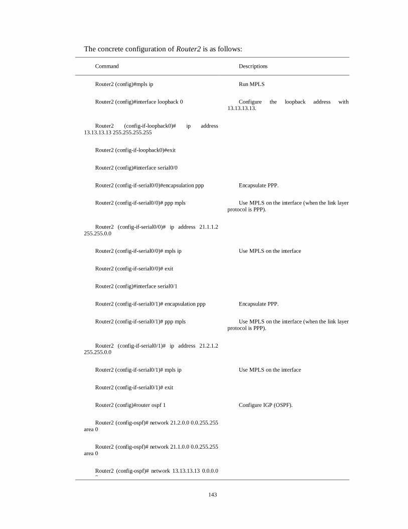
143
The concrete configuration of Router2 is as follows:
Command Descriptions
Router2 (config)#mpls ip Run MPLS
Router2 (config)#interface loopback 0 Configure the loopback address with 13.13.13.13.
Router2 (config-if-loopback0)# ip address 13.13.13.13 255.255.255.255
Router2 (config-if-loopback0)#exit
Router2 (config)#interface serial0/0
Router2 (config-if-serial0/0)#encapsulation ppp Encapsulate PPP.
Router2 (config-if-serial0/0)# ppp mpls Use MPLS on the interface (when the link layer protocol is PPP).
Router2 (config-if-serial0/0)# ip address 21.1.1.2 255.255.0.0
Router2 (config-if-serial0/0)# mpls ip Use MPLS on the interface
Router2 (config-if-serial0/0)# exit
Router2 (config)#interface serial0/1
Router2 (config-if-serial0/1)# encapsulation ppp Encapsulate PPP.
Router2 (config-if-serial0/1)# ppp mpls Use MPLS on the interface (when the link layer protocol is PPP).
Router2 (config-if-serial0/1)# ip address 21.2.1.2 255.255.0.0
Router2 (config-if-serial0/1)# mpls ip Use MPLS on the interface
Router2 (config-if-serial0/1)# exit
Router2 (config)#router ospf 1 Configure IGP (OSPF).
Router2 (config-ospf)# network 21.2.0.0 0.0.255.255 area 0
Router2 (config-ospf)# network 21.1.0.0 0.0.255.255 area 0
Router2 (config-ospf)# network 13.13.13.13 0.0.0.0 0
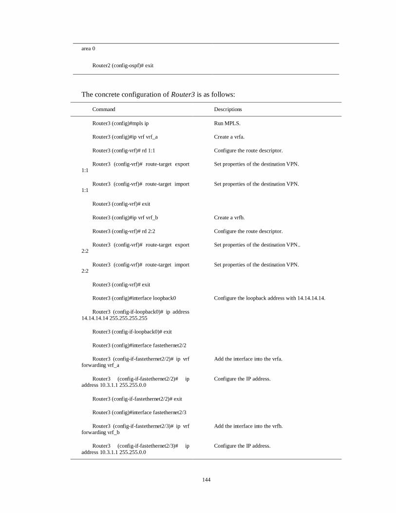
144
area 0
Router2 (config-ospf)# exit
The concrete configuration of Router3 is as follows:
Command Descriptions
Router3 (config)#mpls ip Run MPLS.
Router3 (config)#ip vrf vrf_a Create a vrfa.
Router3 (config-vrf)# rd 1:1 Configure the route descriptor.
Router3 (config-vrf)# route-target export 1:1
Set properties of the destination VPN.
Router3 (config-vrf)# route-target import 1:1
Set properties of the destination VPN.
Router3 (config-vrf)# exit
Router3 (config)#ip vrf vrf_b Create a vrfb.
Router3 (config-vrf)# rd 2:2 Configure the route descriptor.
Router3 (config-vrf)# route-target export 2:2
Set properties of the destination VPN..
Router3 (config-vrf)# route-target import 2:2
Set properties of the destination VPN.
Router3 (config-vrf)# exit
Router3 (config)#interface loopback0 Configure the loopback address with 14.14.14.14.
Router3 (config-if-loopback0)# ip address 14.14.14.14 255.255.255.255
Router3 (config-if-loopback0)# exit
Router3 (config)#interface fastethernet2/2
Router3 (config-if-fastethernet2/2)# ip vrf forwarding vrf_a
Add the interface into the vrfa.
Router3 (config-if-fastethernet2/2)# ip address 10.3.1.1 255.255.0.0
Configure the IP address.
Router3 (config-if-fastethernet2/2)# exit
Router3 (config)#interface fastethernet2/3
Router3 (config-if-fastethernet2/3)# ip vrf forwarding vrf_b
Add the interface into the vrfb.
Router3 (config-if-fastethernet2/3)# ip address 10.3.1.1 255.255.0.0
Configure the IP address.
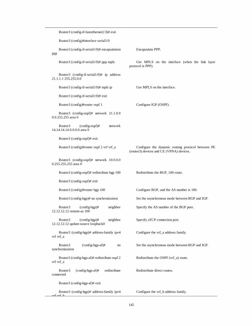
145
Router3 (config-if-fastethernet2/3)# exit
Router3 (config)#interface serial1/0
Router3 (config-if-serial1/0)# encapsulation ppp
Encapsulate PPP.
Router3 (config-if-serial1/0)# ppp mpls Use MPLS on the interface (when the link layer protocol is PPP).
Router3 (config-if-serial1/0)# ip address 21.1.1.1 255.255.0.0
Router3 (config-if-serial1/0)# mpls ip Use MPLS on the interface.
Router3 (config-if-serial1/0)# exit
Router3 (config)#router ospf 1 Configure IGP (OSPF).
Router3 (config-ospf)# network 21.1.0.0 0.0.255.255 area 0
Router3 (config-ospf)# network 14.14.14.14 0.0.0.0 area 0
Router3 (config-ospf)# exit
Router3 (config)#router ospf 2 vrf vrf_a Configure the dynamic routing protocol between PE (router3) devices and CE (VPNA) devices.
Router3 (config-ospf)# network 10.0.0.0 0.255.255.255 area 0
Router3 (config-ospf)# redistribute bgp 100 Redistribute the BGP_100 route.
Router3 (config-ospf)# exit
Router3 (config)#router bgp 100 Configure BGP, and the AS number is 100.
Router3 (config-bgp)# no synchronization Set the asynchronous mode between BGP and IGP.
Router3 (config-bgp)# neighbor 12.12.12.12 remote-as 100
Specify the AS number of the BGP peer.
Router3 (config-bgp)# neighbor 12.12.12.12 update-source loopback0
Specify aTCP connection port.
Router3 (config-bgp)# address-family ipv4 vrf vrf_a
Configure the vrf_a address family.
Router3 (config-bgp-af)# no synchronization
Set the asynchronous mode between BGP and IGP.
Router3 (config-bgp-af)# redistribute ospf 2 vrf vrf_a
Redistribute the OSPF (vrf_a) route.
Router3 (config-bgp-af)# redistribute connected
Redistribute direct routes.
Router3 (config-bgp-af)# exit
Router3 (config-bgp)# address-family ipv4 vrf vrf b
Configure the vrf_b address family.

146
vrf vrf_b
Router3 (config-bgp-af)# no synchronization
Set the asynchronous mode between BGP and IGP.
Router3 (config-bgp-af)# redistribute connected
Redistribute direct routes.
Router3 (config-bgp-af)# exit
Router3 (config-bgp)# address-family vpnv4
Configure the vpn address family.
Router3 (config-bgp-af)# neighbor 12.12.12.12 activate
Router3 (config-bgp-af)# neighbor 12.12.12.12 next-hop-self
Router3 (config-bgp-af)# neighbor 12.12.12.12 send-community extended
Send the properties of the expanded community to the peer.
Router3 (config-bgp-af)# exit
Router3 (config-bgp)# exit
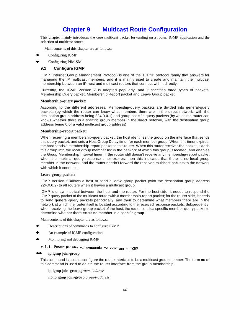
147
Chapter 9 Multicast Route Configuration This chapter mainly introduces the core multicast packet forwarding on a router, IGMP application and the selection of multicast routes.
Main contents of this chapter are as follows:
z Configuring IGMP
z Configuring PIM-SM
9.1 Configure IGMP
IGMP (Internet Group Management Protocol) is one of the TCP/IP protocol family that answers for managing the IP multicast members, and it is mainly used to create and maintain the multicast membership between an IP host and multicast routers that connect with it directly.
Currently, the IGMP Version 2 is adopted popularly, and it specifies three types of packets: Membership Query packet, Membership Report packet and Leave Group packet.
Membership-query packet:
According to the different addresses, Membership-query packets are divided into general-query packets (by which the router can know what members there are in the direct network, with the destination group address being 224.0.0.1) and group-specific-query packets (by which the router can knows whether there is a specific group member in the direct network, with the destination group address being 0 or a valid multicast group address).
Membership-report packet:
When receiving a membership-query packet, the host identifies the group on the interface that sends this query packet, and sets a Host Group Delay timer for each member group. When this timer expires, the host sends a membership-report packet to this router. When this router receives the packet, it adds this group into the local group member list in the network at which this group is located, and enables the Group Membership Interval timer. If the router still doesn’t receive any membership-report packet when the maximal query response timer expires, then this indicates that there is no local group member in the network, and the router needn’t forward the received multicast packets to the network with which it connects.
Leave-group packet:
IGMP Version 2 allows a host to send a leave-group packet (with the destination group address 224.0.0.2) to all routers when it leaves a multicast group.
IGMP is unsymmetrical between the host and the router. For the host side, it needs to respond the IGMP query packet of the multicast router with a membership-report packet; for the router side, it needs to send general-query packets periodically, and then to determine what members there are in the network at which the router itself is located according to the received response packets. Subsequently, when receiving the leave-group packet of the host, the router sends a specific-member-query packet to determine whether there exists no member in a specific group.
Main contents of this chapter are as follows:
z Descriptions of commands to configure IGMP
z An example of IGMP configuration
z Monitoring and debugging IGMP
���������� ''HHVFVFUULSLSWWLRLRQQV RV RII FFRRPPPPDDQGQGVV WWRR FFRRQIQILLJXJXUUH ,H ,**0303
zz ip igmp join-group
This command is used to configure the router interface to be a multicast group member. The form no of this command is used to delete the router interface from the group membership.
ip igmp join-group groups-address
no ip igmp join-group groups-address
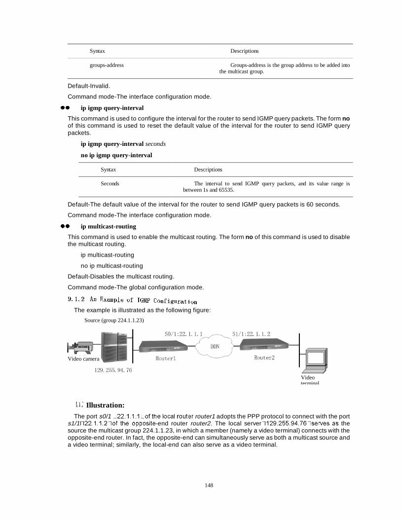
148
Syntax Descriptions
groups-address Groups-address is the group address to be added into the multicast group.
Default-Invalid.
Command mode-The interface configuration mode.
zz ip igmp query-interval
This command is used to configure the interval for the router to send IGMP query packets. The form no of this command is used to reset the default value of the interval for the router to send IGMP query packets.
ip igmp query-interval seconds
no ip igmp query-interval
Syntax Descriptions
Seconds The interval to send IGMP query packets, and its value range is between 1s and 65535.
Default-The default value of the interval for the router to send IGMP query packets is 60 seconds.
Command mode-The interface configuration mode.
zz ip multicast-routing
This command is used to enable the multicast routing. The form no of this command is used to disable the multicast routing.
ip multicast-routing
no ip multicast-routing
Default-Disables the multicast routing.
Command mode-The global configuration mode.
���������� $$QQ (([[DPDPSSOH RIOH RI ,,*0*033 &&RRQIQILLJXJXUUDWDWLLRQRQ
The example is illustrated as the following figure:
Illustration:
The port s0/1 ����������RI WKH ORFDO URXWHU router1 adopts the PPP protocol to connect with the port s1/1����������RI WKH RSSRVLWH-end router router2. The local server���������������VHUYHV DV the source the multicast group 224.1.1.23, in which a member (namely a video terminal) connects with the opposite-end router. In fact, the opposite-end can simultaneously serve as both a multicast source and a video terminal; similarly, the local-end can also serve as a video terminal.
Video camera
Video terminal
Source (group 224.1.1.23)
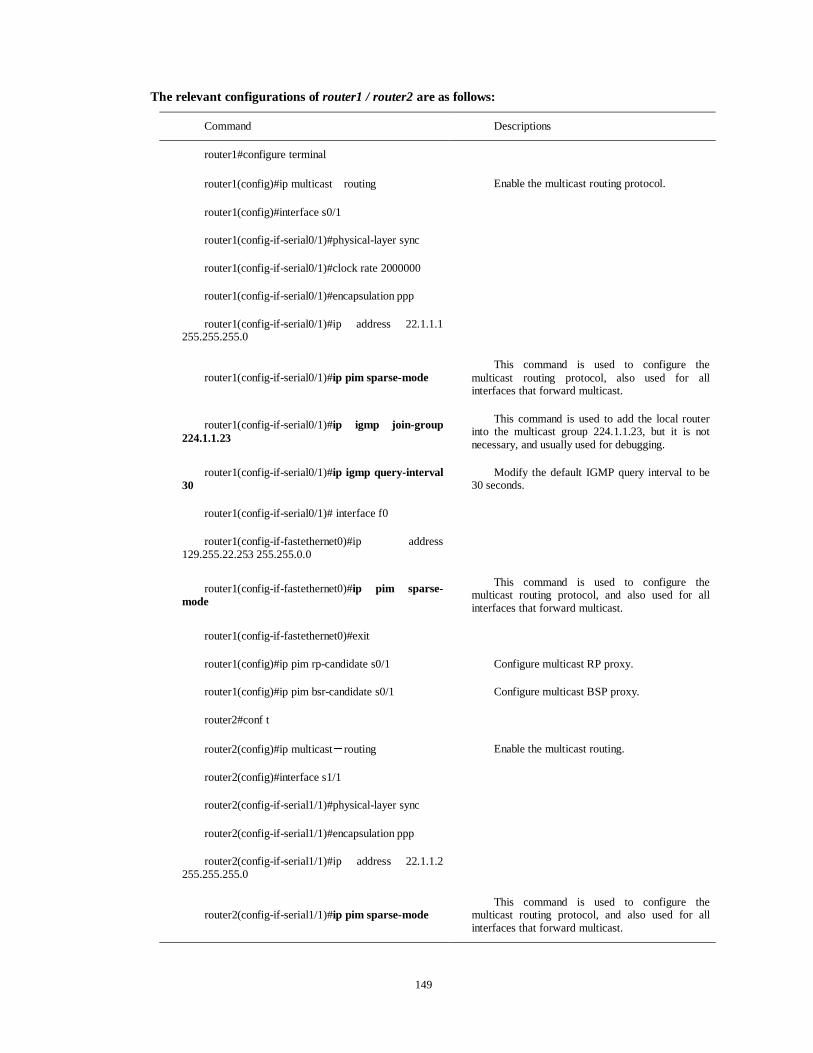
149
The relevant configurations of router1 / router2 are as follows:
Command Descriptions
router1#configure terminal
router1(config)#ip multicastÉrouting Enable the multicast routing protocol.
router1(config)#interface s0/1
router1(config-if-serial0/1)#physical-layer sync
router1(config-if-serial0/1)#clock rate 2000000
router1(config-if-serial0/1)#encapsulation ppp
router1(config-if-serial0/1)#ip address 22.1.1.1 255.255.255.0
router1(config-if-serial0/1)#ip pim sparse-mode This command is used to configure the
multicast routing protocol, also used for all interfaces that forward multicast.
router1(config-if-serial0/1)#ip igmp join-group 224.1.1.23
This command is used to add the local router into the multicast group 224.1.1.23, but it is not necessary, and usually used for debugging.
router1(config-if-serial0/1)#ip igmp query-interval 30
Modify the default IGMP query interval to be 30 seconds.
router1(config-if-serial0/1)# interface f0
router1(config-if-fastethernet0)#ip address 129.255.22.253 255.255.0.0
router1(config-if-fastethernet0)#ip pim sparse-mode
This command is used to configure the multicast routing protocol, and also used for all interfaces that forward multicast.
router1(config-if-fastethernet0)#exit
router1(config)#ip pim rp-candidate s0/1 Configure multicast RP proxy.
router1(config)#ip pim bsr-candidate s0/1 Configure multicast BSP proxy.
router2#conf t
router2(config)#ip multicastÉrouting Enable the multicast routing.
router2(config)#interface s1/1
router2(config-if-serial1/1)#physical-layer sync
router2(config-if-serial1/1)#encapsulation ppp
router2(config-if-serial1/1)#ip address 22.1.1.2 255.255.255.0
router2(config-if-serial1/1)#ip pim sparse-mode This command is used to configure the
multicast routing protocol, and also used for all interfaces that forward multicast.
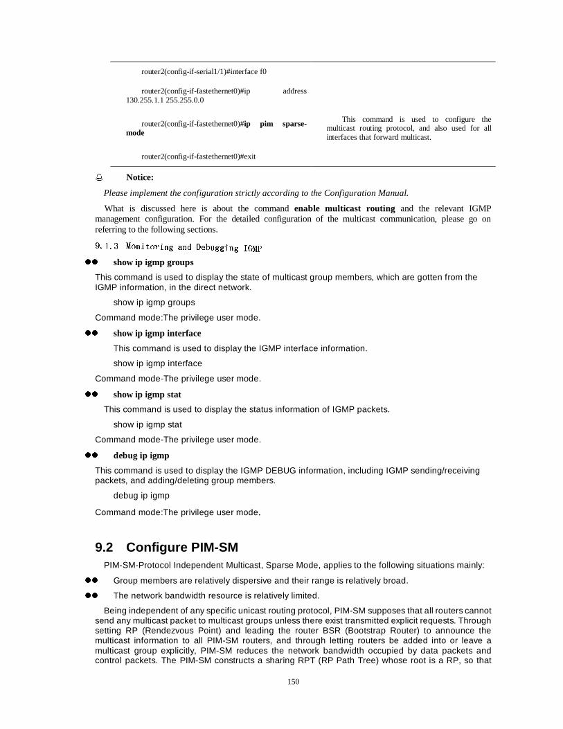
150
router2(config-if-serial1/1)#interface f0
router2(config-if-fastethernet0)#ip address 130.255.1.1 255.255.0.0
router2(config-if-fastethernet0)#ip pim sparse-mode
This command is used to configure the multicast routing protocol, and also used for all interfaces that forward multicast.
router2(config-if-fastethernet0)#exit
�� Notice:
Please implement the configuration strictly according to the Configuration Manual.
What is discussed here is about the command enable multicast routing and the relevant IGMP management configuration. For the detailed configuration of the multicast communication, please go on referring to the following sections.
���������� 00RRQLQLWWRURULLQJ DQG 'HQJ DQG 'HEEXJXJJJLQLQJJ ,,**0303
zz show ip igmp groups
This command is used to display the state of multicast group members, which are gotten from the IGMP information, in the direct network.
show ip igmp groups
Command mode:The privilege user mode.
zz show ip igmp interface
This command is used to display the IGMP interface information.
show ip igmp interface
Command mode-The privilege user mode.
zz show ip igmp stat
This command is used to display the status information of IGMP packets.
show ip igmp stat
Command mode-The privilege user mode.
zz debug ip igmp
This command is used to display the IGMP DEBUG information, including IGMP sending/receiving packets, and adding/deleting group members.
debug ip igmp
Command mode:The privilege user mode.
9.2 Configure PIM-SM PIM-SM-Protocol Independent Multicast, Sparse Mode, applies to the following situations mainly:
zz Group members are relatively dispersive and their range is relatively broad.
zz The network bandwidth resource is relatively limited.
Being independent of any specific unicast routing protocol, PIM-SM supposes that all routers cannot send any multicast packet to multicast groups unless there exist transmitted explicit requests. Through setting RP (Rendezvous Point) and leading the router BSR (Bootstrap Router) to announce the multicast information to all PIM-SM routers, and through letting routers be added into or leave a multicast group explicitly, PIM-SM reduces the network bandwidth occupied by data packets and control packets. The PIM-SM constructs a sharing RPT (RP Path Tree) whose root is a RP, so that
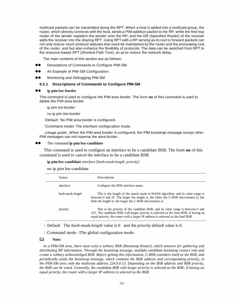
151
multicast packets can be transmitted along the RPT. When a host is added into a multicast group, the router, which directly connects with the host, sends a PIM-addition packet to the RP; while the first hop router of the sender registers the sender onto the RP; and the DR (Specified Router) of the receiver adds the receiver into the sharing RPT. Using RPT with a RP serving as its root to forward packets can not only reduce much protocol statuses that need be maintained by the router and the processing cost of the router, and but also enhance the flexibility of protocols. The data can be switched from RPT to the resource-based SPT (Shortest Path Tree), so as to reduce the network delay.
The main contents of this section are as follows:
zz Descriptions of Commands to Configure PIM-SM
zz An Example of PIM-SM Configuration
zz Monitoring and Debugging PIM-SM
9.2.1 Descriptions of Commands to Configure PIM-SM
zz ip pim bsr-border
This command is used to configure the PIM area border. The form no of this command is used to delete the PIM area border.
ip pim bsr-border
no ip pim bsr-border
�Default�No PIM area border is configured.
�Command mode�The interface configuration mode.
�Usage guide�When the PIM area border is configured, the PIM bootstrap message except other PIM messages can not traverse the area border.
zz The command ip pim bsr-candidate
This command is used to configure an interface to be a candidate BSR. The form no of this command is used to cancel the interface to be a candidate BSR.
ip pim bsr-candidate interface [hash-mask-length priority]
no ip pim bsr-candidate
Syntax Descriptions
interface Configure the BSR interface name.
hash-mask-length This is the length of the match mask in HASH algorithm, and its value range is between 0 and 32. The larger the length is, the littler the C-BSR discreteness is; the little the length is, the larger the C-BSR discreteness is.
priority This is the priority of the candidate BSR, and its value range is between 0 and 255. The candidate BSR with larger priority is selected as the final BSR; if having an equal priority, the router with a larger IP address is selected as the final BSR.
�Default�The hash-mask-length value is 0�DQG the priority default value is 0.
�Command mode�The global configuration mode.
Note:
In a PIM-SM area, there must exist a solitary BSR (Bootstrap Router), which answers for gathering and distributing RP information. Through the bootstrap message, multiple candidate bootstrap routers vote and create a solitary acknowledged BSR. Before getting this information, C-BSR considers itself as the BSR, and periodically sends the bootstrap message, which contains the BSR address and corresponding priority, in the PIM-SM area with the multicast address 224.0.0.13. Depending on the BSR address and BSR priority, the BSR can be voted. Generally, the candidate BSR with larger priority is selected as the BSR; if having an equal priority, the router with a larger IP address is selected as the BSR.
152
zz ip pim query-interval
This command is used to configure the interval for the interface to send a PIM Hello packet. The form no of this command is used to reset the default value of the interval for the interface to send a PIM Hello packet.
ip pim query-interval seconds
no ip pim query-interval
Syntax Descriptions
seconds This is the interval for the interface to send PIM Hello packet, and its value range is between 1s and 65535s.
�Default�The interval is 30 seconds.
�Command mode�The interface configuration mode.
zz ip pim rp-candidate
This command is used to configure an interface to be a candidate RP. The form no of this command is used to cancel the interface to be a candidate RP.
ip pim rp-candidate interface [group-list access-list-number]
no ip pim rp-candidate interface
Syntax Descriptions
interface This is the interface that is configured as a candidate RP.
access-list-number This is the standard IP access list number, and its value range is between 1 and 1000. And the range is also the service range of the announced RP.
�Default�If this command is not followed by the parameter group-list, then it indicates that this RP is the candidate RP for all groups.
�Command mode�The global configuration mode.
Note:
In PIM-SM protocol, the sharing RPT (RP Path Tree) that is created by the route multicast data contains one root (one rendezvous point) and multiple leaves (multiple group members). The RP is voted through BSR selection. After the BSR is generated, all C-RPs (Candidate RP) unicasts C-RP messages to the BSR periodically,, and then the BSR diffuse these messages to the entire PIM area.
It is suggested that the C-RP of the corresponding multicast group should be as close to the corresponding multicast source as possible when it is configured.
zz ip pim sparse-mode
This command is used to enable PIM-SM protocol on the interface, simultaneously, to enable IGMP protocol (of the router version) on the interface if it is not enabled yet. The form no of this command is used to disable PIM-SM protocol on the interface.
ip pim sparse-mode
no ip pim sparse-mode
�Default� PIM-SM is disabled on an interface.
�Command mode�The interface configuration mode.
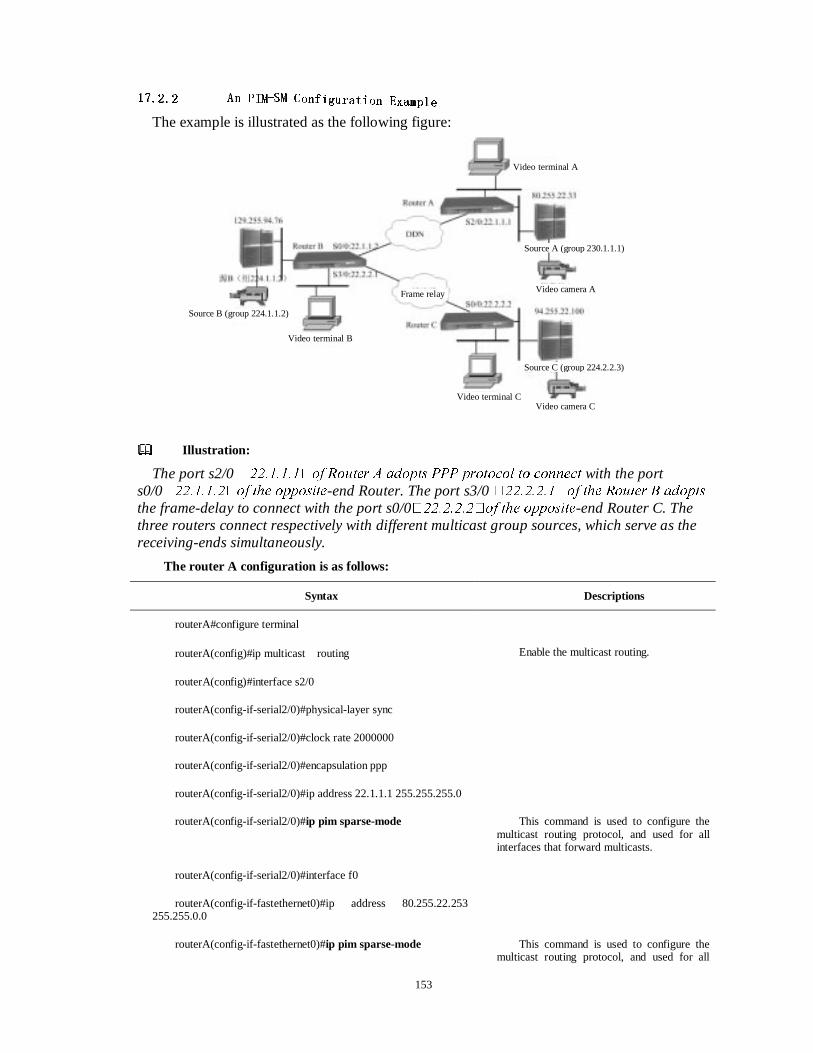
153
������������ $$QQ 33,,00��6600 &&RRQIQILLJXJXUUDWLDWLRRQQ (([D[DPPSOSOHH
The example is illustrated as the following figure:
Illustration:
The port s2/0 ����������RI 5RXWHU $ DGRSWV 333 SURWRFRO WR FRQQHFW with the port s0/0����������RI WKH RSSRVLWH-end Router. The port s3/0 ����������RI WKH 5RXWHU % DGRSWV
the frame-delay to connect with the port s0/0����������RI WKH RSSRVLWH-end Router C. The three routers connect respectively with different multicast group sources, which serve as the receiving-ends simultaneously.
The router A configuration is as follows:
Syntax Descriptions
routerA#configure terminal
routerA(config)#ip multicastÉrouting Enable the multicast routing.
routerA(config)#interface s2/0
routerA(config-if-serial2/0)#physical-layer sync
routerA(config-if-serial2/0)#clock rate 2000000
routerA(config-if-serial2/0)#encapsulation ppp
routerA(config-if-serial2/0)#ip address 22.1.1.1 255.255.255.0
routerA(config-if-serial2/0)#ip pim sparse-mode This command is used to configure the multicast routing protocol, and used for all interfaces that forward multicasts.
routerA(config-if-serial2/0)#interface f0
routerA(config-if-fastethernet0)#ip address 80.255.22.253 255.255.0.0
routerA(config-if-fastethernet0)#ip pim sparse-mode This command is used to configure the multicast routing protocol, and used for all
Video camera A
Video camera C
Frame relay
Video terminal B
Video terminal C
Video terminal A
Source A (group 230.1.1.1)
Source C (group 224.2.2.3)
Source B (group 224.1.1.2)
154
interfaces that forward multicasts.
routerA(config-if-fastethernet0)#exit
routerA(config)#ip access-list standard 1 Configure the standard access list.
routerA(config-std-nacl)#permit host 230.1.1.1 Configure the usage range of the access list.
routerA(config-std-nacl)#exit
routerA(config)#ip pim rp-candidate fastethernet0 group-list 1 Configure the RP proxy of the specified group.
routerA(config)#ip pim bsr-candidate s2/0 Configure the multicast BSR proxy.
routerA(config)#router ospf
routerA(config-ospf)#network 22.1.1.0 0.0.0.255 area 5
routerA(config-ospf)#network 80.255.0 0.0.255.255 area 5
The router B configuration is as follows:
Syntax Descriptions
routerB(config)# configure terminal
routerB(config)#ip multicastÉrouting Enable the multicast routing.
routerB(config)#frame-relay switching
routerB(config)#interface s0/0
routerB(config-if-serial0/0)#physical-layer sync sync
routerB(config-if-serial0/0)#encapsulation ppp
routerB(config-if-serial0/0)#ip address 22.1.1.2 255.255.255.0
routerB(config-if-serial0/0)#ip pim sparse-mode This command is used configure the multicast routing protocol, and used for all interfaces that forward multicasts.
routerB(config-if-serial0/0)#interface f0
routerB(config-if-fastethernet0)#ip address 129.255.22.253 255.255.0.0
routerB(config-if-fastethernet0)#ip pim sparse-mode This command is used to configure the multicast routing protocol, and used for all interfaces that forward multicasts.
routerB(config-if-fastethernet0)#interface serial3/0
routerB(config-if-serial3/0)#clock rate 2000000
routerB(config-if-serial3/0)#ip address 22.2.2.1 255.255.255.0
routerB(config-if-serial3/0)#ip pim sparse-mode
155
routerB(config-if-serial3/0)#encapsulation frame-relay
routerB(config-if-serial3/0)#frame-relay intf-type dce
routerB(config-if-serial3/0)#frame-relay interface-dlci 100
routerB(config-if-serial3/0)#frame-relay map ip 22.2.2.2 100 broadcast
routerB(config-if-serial3/0)#exit
routerB(config)#ip access-list standard 1 Configure the standard access list.
routerB(config-std-nacl)#permit host 224.1.1.2 Configure the usage range of the access list.
routerB(config-std-nacl)#exit
routerB(config)#ip pim rp-candidate fastethernet0 group-list 1
Configure the RP proxy of a specific group.
routerB(config)#router ospf
routerB(config-ospf)#network 22.0.0.0 0.255.255.255 area 5
Enable the OSFP on ports s0/0 and s3/0..
routerB(config-ospf)#network 129.255.0.0 0.0.255.255.255 area 5
Enable the OSFP on the port f0.
The Router C is configured as follows:
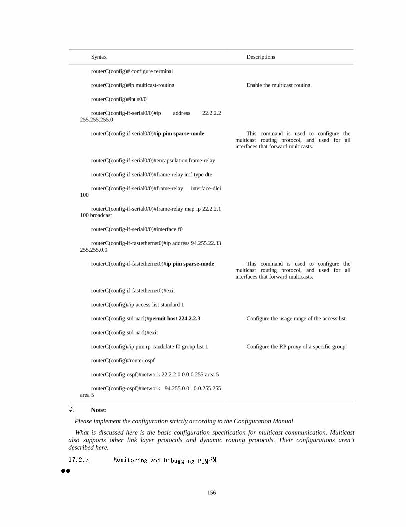
156
�� Note:
Please implement the configuration strictly according to the Configuration Manual.
What is discussed here is the basic configuration specification for multicast communication. Multicast also supports other link layer protocols and dynamic routing protocols. Their configurations aren’t described here.
������������ 00RRQLQLWWRURULLQJ DQG 'HQJ DQG 'HEEXJXJJJLQLQJJ 33,,00��6600
zz
Syntax Descriptions
routerC(config)# configure terminal
routerC(config)#ip multicast-routing Enable the multicast routing.
routerC(config)#int s0/0
routerC(config-if-serial0/0)#ip address 22.2.2.2 255.255.255.0
routerC(config-if-serial0/0)#ip pim sparse-mode This command is used to configure the multicast routing protocol, and used for all interfaces that forward multicasts.
routerC(config-if-serial0/0)#encapsulation frame-relay
routerC(config-if-serial0/0)#frame-relay intf-type dte
routerC(config-if-serial0/0)#frame-relay interface-dlci 100
routerC(config-if-serial0/0)#frame-relay map ip 22.2.2.1 100 broadcast
routerC(config-if-serial0/0)#interface f0
routerC(config-if-fastethernet0)#ip address 94.255.22.33 255.255.0.0
routerC(config-if-fastethernet0)#ip pim sparse-mode This command is used to configure the multicast routing protocol, and used for all interfaces that forward multicasts.
routerC(config-if-fastethernet0)#exit
routerC(config)#ip access-list standard 1
routerC(config-std-nacl)#permit host 224.2.2.3 Configure the usage range of the access list.
routerC(config-std-nacl)#exit
routerC(config)#ip pim rp-candidate f0 group-list 1 Configure the RP proxy of a specific group.
routerC(config)#router ospf
routerC(config-ospf)#network 22.2.2.0 0.0.0.255 area 5
routerC(config-ospf)#network 94.255.0.0 0.0.255.255 area 5
157
zz show ip mcache
This command is used to display the cache information of the core multicast route.
show ip mcache
�Command mode�The privilege user mode.
zz show ip mroute
This command is used to display the information about a PIM multicast route list.
show ip mroute
�Command mode�The privilege user mode.
zz show ip pim bsr
This command is used to display the information about the PIM bootstrap router.
show ip pim bsr
�Command mode�The privilege user mode.
zz show ip pim interface
This command is used to display the information about the PIM interface.
show ip pim interface
�Command mode�The privilege user mode.
zz show ip pim neighbor
This command is used to display the information about PIM neighbors.
show ip pim neighbor
�Command mode�The privilege user mode.
zz show ip pim rp
This command is used to display the information about the PIM RP (Rendezvous Point).
show ip pim rp
�Command mode�The privilege user mode.
158
Chapter 10 IP Telephone Configuration IP telephone configuration generally refers to the system that processes voice communication on the IP network. IP telephone system has been integrated into Dax-Maipu. And users can use the IP telephone module provided by the router to process voice communication. Presently, Dax-Maipu supports the H.323 protocols family, the mainstream protocols of the IP telephone system. H.323 protocols family mainly includes H.225-Call Control Protocol, H.245-Multimedia Control Protocol, and RTP/RTCP --Realtime Transmission Protocol/Realtime Transmission Control Protocol. This chapter mainly describes how to configure Dax voice card, including how the FXS card accesses PSTN/PBX through the FXO card, how the FXS cards intercommunicate between them, how to configure Dax-Maipu as the H.323 voice gateway, and some optional extended configuration. The main contents of this chapter are as follows: Configuring the voice card interface Configuring voip Configuring Dax-Maipu as the H.323 voice gateway The debugging switch of IP telephone Section 1 Configure Voice Card Interface Dax-Maipu series supports two kinds of voice cards: FXS Foreign eXchange Station interface card, is used to connect general telephone or the exterior line of mini PBX. FXOForeign eXchange Office interface card, is used to connect PSTN telephone line or the interior line of PBX. The main contents of this section are as follows: The relevant commands A simple example of configuration 1.1 The Relevant Commands The command to enter the voice port in the global configuration mode: Router-config voice-port
Command Description
<STRING> This is the voice card interface.
Note: 1. If there is an IP telephone module of old version router, the voice card interface is a single number, for example, 0, 1 etc. 2. If there is an IP telephone module of new version router, the voice card interface is the format of x/y, of which x is the WAN port number while y is the voice port number. For example, inserting the module in the WAN port s3 and using channel 1, then the voice port number is 3/1. 3. The number of a concrete interface can be examined through the command show run . After entering the voice port: Router-config--voice-port 0 Router-config-voice-port#
Command Description
Codec <g723 / g729 / g711a> This command is used to configure voice-coding type. There are G.711a, G.723 and G.729 to be selected, which correspond to different codings and compression algorithms. And the typical ones are G.729 and G.723. If a kind of voice codeing is selected, the router will negotiate it firstly.
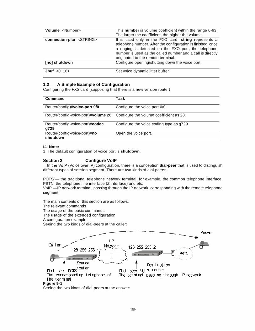
159
Volume <Number> This number is volume coefficient within the range 0-63. The larger the coefficient, the higher the volume.
connection-plar <STRING> It is used only in the FXO card; string represents a telephone number. After the configuration is finished, once a ringing is detected on the FXO port, the telephone number is used as the called number and a call is directly originated to the remote terminal.
[no] shutdown Configure opening/shutting down the voice port.
Jbuf <0_16> Set voice dynamic jitter buffer
1.2 A Simple Example of Configuration Configuring the FXS card (supposing that there is a new version router)
Command Task
Router(config)#voice-port 0/0 Configure the voice port 0/0.
Router(config-voice-port)#volume 28 Configure the volume coefficient as 28.
Router(config-voice-port)#codec g729
Configure the voice coding type as g729
Router(config-voice-port)#no shutdown
Open the voice port.
Note: 1. The default configuration of voice port is shutdown . Section 2 Configure VoIP
In the VoIP (Voice over IP) configuration, there is a conception dial-peer that is used to distinguish different types of session segment. There are two kinds of dial-peers: POTS — the traditional telephone network terminal, for example, the common telephone interface, PSTN, the telephone line interface (Z interface) and etc. VoIP — IP network terminal, passing through the IP network, corresponding with the remote telephone segment. The main contents of this section are as follows: The relevant commands The usage of the basic commands The usage of the extended configuration A configuration example Seeing the two kinds of dial-peers at the caller:
, 3
1HW ZRU N
3671
6RXU FH
U RXW HU'HVW L QDW L RQ
U RXW HU'L DO SHHU 9R, 37KH W HUPL QDO SDVVL QJ W KU RXJK , 3 QHW ZRU N
'L DO SHHU 32767KH FRU U HVSRQGL QJ W HO HSKRQH RIW KH W HUPL QDO
��� ��� ��� ���� ��� ��� �
&DO O HU
$QVZHU
Figure 9-1 Seeing the two kinds of dial-peers at the answer:
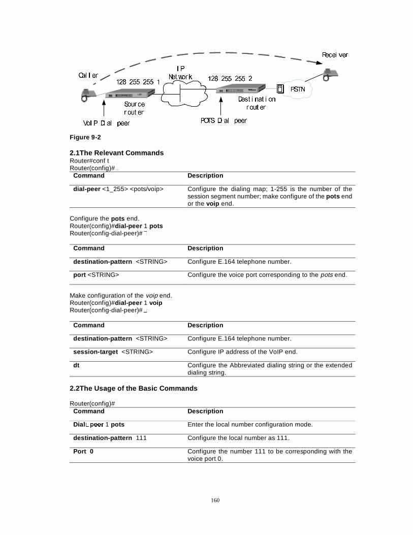
160
, 3
1HW ZRU N
3671
6RXU FH
U RXW HU
'HVW L QDW L RQ
U RXW HU
3276 'L DO SHHU9R, 3 'L DO SHHU
��� ��� ��� ���� ��� ��� �
&DO O HU
5HFHL YHU
Figure 9-2 2.1The Relevant Commands Router#conf t Router(config)#�
Command Description
dial-peer <1_255> <pots/voip> Configure the dialing map; 1-255 is the number of the session segment number; make configure of the pots end or the voip end.
Configure the pots end. Router(config)#dial-peer 1 pots Router(config-dial-peer)#�
Command Description
destination-pattern <STRING> Configure E.164 telephone number.
port <STRING> Configure the voice port corresponding to the pots end.
Make configuration of the voip end. Router(config)#dial-peer 1 voip Router(config-dial-peer)#�
Command Description
destination-pattern <STRING> Configure E.164 telephone number.
session-target <STRING> Configure IP address of the VoIP end.
dt Configure the Abbreviated dialing string or the extended dialing string.
2.2The Usage of the Basic Commands Router(config)#
Command Description
Dial�SHHU 1 pots Enter the local number configuration mode.
destination-pattern 111 Configure the local number as 111.
Port 0 Configure the number 111 to be corresponding with the voice port 0.
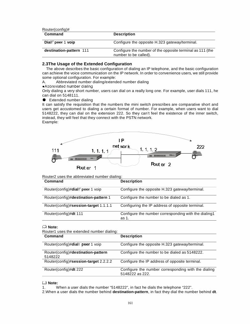
161
Router(config)# Command Description
Dial�SHHU 1 voip Configure the opposite H.323 gateway/terminal.
destination-pattern 111 Configure the number of the opposite terminal as 111 (the number to be called).
2.3The Usage of the Extended Configuration
The above describes the basic configuration of dialing an IP telephone, and the basic configuration can achieve the voice communication on the IP network. In order to convenience users, we still provide some optional configuration. For example: A. Abbreviated number dialing/extended number dialing �$EEUHYLDWHG QXPEHU GLDOLQJ Only dialing a very short number, users can dial on a really long one. For example, user dials 111, he can dial on 5148111. ½ Extended number dialing It can satisfy the requisition that the numbers the mini switch prescribes are comparative short and users get accustomed to dialing a certain format of number. For example, when users want to dial 5148222, they can dial on the extension 222. So they can’t feel the existence of the inner switch, instead, they will feel that they connect with the PSTN network. Example:
,, 33
QQHHWW ZZRRUU NN
55RRXXWW HHUU ��55RRXXWW HHUU ��
���� ���� ���� ������ ���� ���� ��������
������
Router2 uses the abbreviated number dialing:
Command Description
Router(config)#dial�SHHU 1 voip Configure the opposite H.323 gateway/terminal.
Router(config)#destination-pattern 1 Configure the number to be dialed as 1.
Router(config)#session-target 1.1.1.1 Configuring the IP address of opposite terminal.
Router(config)#dt 111 Configure the number corresponding with the dialing1 as 1.
Note: Router1 uses the extended number dialing:
Command Description
Router(config)#dial �SHHU 1 voip Configure the opposite H.323 gateway/terminal.
Router(config)#destination-pattern 5148222
Configure the number to be dialed as 5148222.
Router(config)#session-target 2.2.2.2 Configure the IP address of opposite terminal.
Router(config)#dt 222 Configure the number corresponding with the dialing 5148222 as 222.
Note: 1. When a user dials the number “5148222”, in fact he dials the telephone “222”. 2.When a user dials the number behind destination-pattern , in fact they dial the number behind dt .
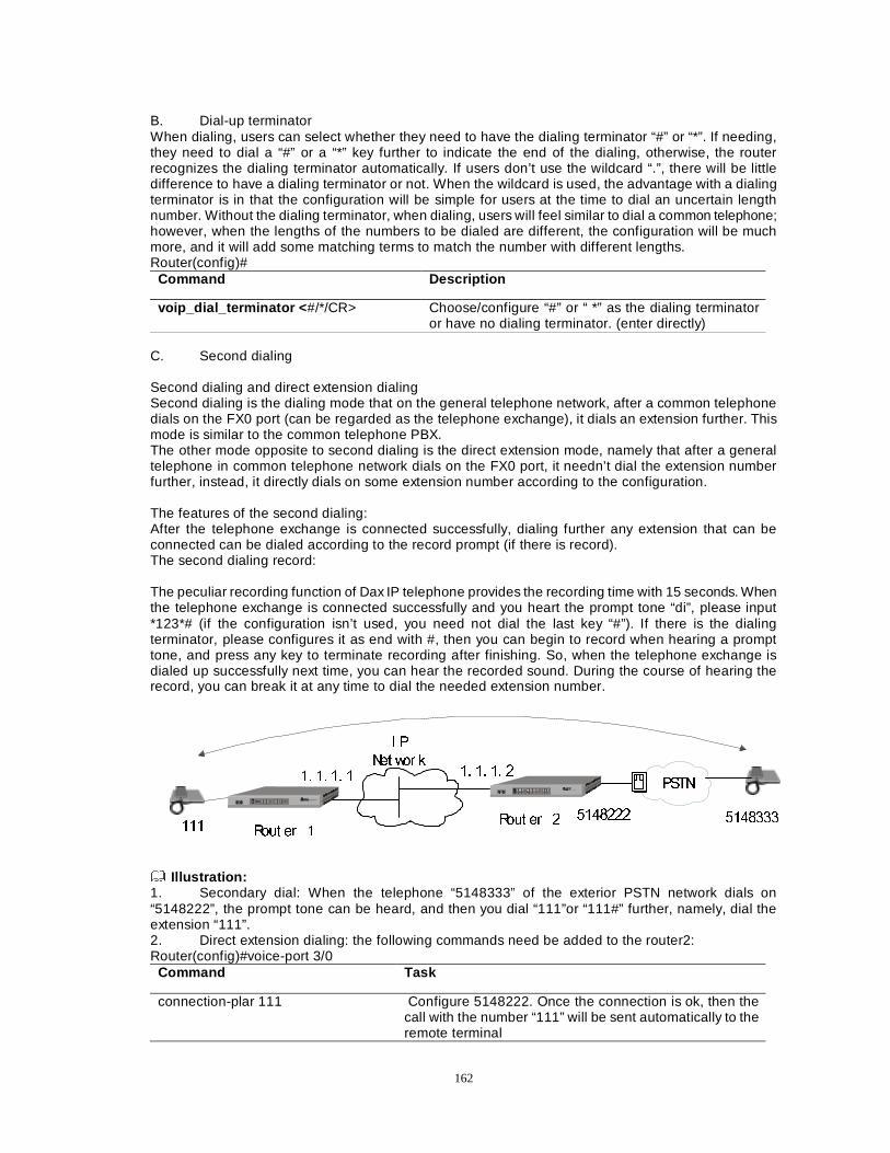
162
B. Dial-up terminator When dialing, users can select whether they need to have the dialing terminator “#” or “*”. If needing, they need to dial a “#” or a “*” key further to indicate the end of the dialing, otherwise, the router recognizes the dialing terminator automatically. If users don’t use the wildcard “.”, there will be little difference to have a dialing terminator or not. When the wildcard is used, the advantage with a dialing terminator is in that the configuration will be simple for users at the time to dial an uncertain length number. Without the dialing terminator, when dialing, users will feel similar to dial a common telephone; however, when the lengths of the numbers to be dialed are different, the configuration will be much more, and it will add some matching terms to match the number with different lengths. Router(config)#
Command Description
voip_dial_terminator < #/*/CR> Choose/configure “#” or “ *” as the dialing terminator or have no dialing terminator. (enter directly)
C. Second dialing Second dialing and direct extension dialing Second dialing is the dialing mode that on the general telephone network, after a common telephone dials on the FX0 port (can be regarded as the telephone exchange), it dials an extension further. This mode is similar to the common telephone PBX. The other mode opposite to second dialing is the direct extension mode, namely that after a general telephone in common telephone network dials on the FX0 port, it needn’t dial the extension number further, instead, it directly dials on some extension number according to the configuration. The features of the second dialing: After the telephone exchange is connected successfully, dialing further any extension that can be connected can be dialed according to the record prompt (if there is record). The second dialing record: The peculiar recording function of Dax IP telephone provides the recording time with 15 seconds. When the telephone exchange is connected successfully and you heart the prompt tone “di”, please input *123*# (if the configuration isn’t used, you need not dial the last key “#”). If there is the dialing terminator, please configures it as end with #, then you can begin to record when hearing a prompt tone, and press any key to terminate recording after finishing. So, when the telephone exchange is dialed up successfully next time, you can hear the recorded sound. During the course of hearing the record, you can break it at any time to dial the needed extension number.
, 3
1HW ZRU N
5RXW HU �5RXW HU �
�� �� �� � �� �� �� �
����������
3671
�������
Illustration: 1. Secondary dial: When the telephone “5148333” of the exterior PSTN network dials on “5148222”, the prompt tone can be heard, and then you dial “111”or “111#” further, namely, dial the extension “111”. 2. Direct extension dialing: the following commands need be added to the router2: Router(config)#voice-port 3/0
Command Task
connection-plar 111 Configure 5148222. Once the connection is ok, then the call with the number “111” will be sent automatically to the remote terminal
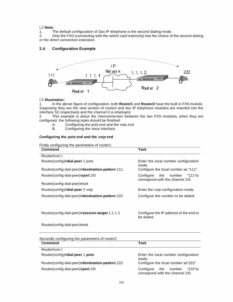
163
Note: 1. The default configuration of Dax IP telephone is the second dialing mode. 2. Only the FXO (connecting with the switch card exteriorly) has the choice of the second dialing or the direct connection extension. 2.4 Configuration Example
, 3
1HW ZRU N
5RXW HU �5RXW HU �
�� �� �� ��� �� �� �
������
Illustration: 1. In the above figure of configuration, both Router1 and Router2 have the built-in FXS module. Supposing they are the new version of routers and two IP telephone modules are inserted into the interface S2 respectively and the channel 0 is employed. 2. This example is about the interconnection between the two FXS modules, when they are configured, the following tasks should be finished: A. Configuring the pots end and the voip end B. Configuring the voice interface Configuring the pots end and the voip end Firstly configuring the parameters of router1:
Command Task
Router#con t
Router(config)#dial-peer 1 pots Enter the local number configuration mode.
Router(config-dial-peer)#destination-pattern 111 Configure the local number as “111”.
Router(config-dial-peer)#port 2/0 Configure the number “111”to correspond with the channel 2/0.
Router(config-dial-peer)#exit
Router(config)#dial-peer 2 voip Enter the voip configuration mode.
Router(config-dial-peer)#destination-pattern 222 Configure the number to be dialed.
Router(config-dial-peer)#session-target 1.1.1.2 Configure the IP address of the end to be dialed.
Router(config-dial-peer)#exit
Secondly configuring the parameters of router2:
Command Task
Router#con t
Router(config)#dial-peer 1 pots Enter the local number configuration mode.
Router(config-dial-peer)#destination-pattern 222 Configure the local number as“222”.
Router(config-dial-peer)#port 2/0 Configure the number “222”to correspond with the channel 2/0.
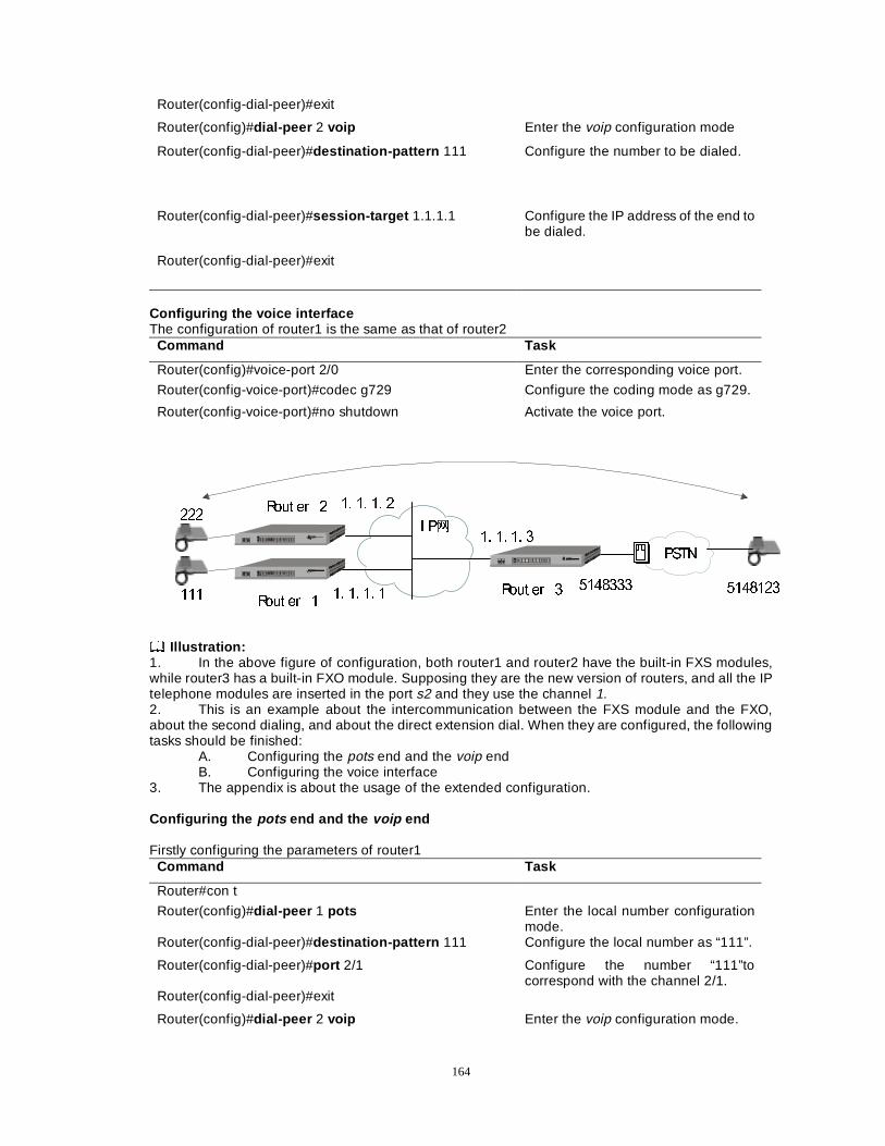
164
Router(config-dial-peer)#exit
Router(config)#dial-peer 2 voip Enter the voip configuration mode
Router(config-dial-peer)#destination-pattern 111
Configure the number to be dialed.
Router(config-dial-peer)#session-target 1.1.1.1 Configure the IP address of the end to be dialed.
Router(config-dial-peer)#exit
Configuring the voice interface The configuration of router1 is the same as that of router2
Command Task
Router(config)#voice-port 2/0 Enter the corresponding voice port.
Router(config-voice-port)#codec g729 Configure the coding mode as g729.
Router(config-voice-port)#no shutdown Activate the voice port.
, 3×
5RXW HU �5RXW HU ��� �� �� �
�� �� �� �
����������
3671
�������
�� �� �� ����
5RXW HU �
Illustration: 1. In the above figure of configuration, both router1 and router2 have the built-in FXS modules, while router3 has a built-in FXO module. Supposing they are the new version of routers, and all the IP telephone modules are inserted in the port s2 and they use the channel 1. 2. This is an example about the intercommunication between the FXS module and the FXO, about the second dialing, and about the direct extension dial. When they are configured, the following tasks should be finished: A. Configuring the pots end and the voip end B. Configuring the voice interface 3. The appendix is about the usage of the extended configuration. Configuring the pots end and the voip end Firstly configuring the parameters of router1
Command Task
Router#con t
Router(config)#dial-peer 1 pots Enter the local number configuration mode.
Router(config-dial-peer)#destination-pattern 111 Configure the local number as “111”.
Router(config-dial-peer)#port 2/1 Configure the number “111”to correspond with the channel 2/1.
Router(config-dial-peer)#exit
Router(config)#dial-peer 2 voip Enter the voip configuration mode.
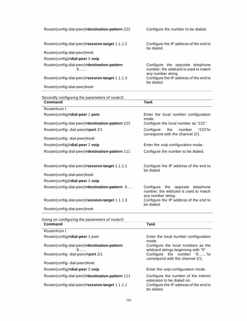
165
Router(config-dial-peer)#destination-pattern 222 Configure the number to be dialed.
Router(config-dial-peer)#session-target 1.1.1.2 Configure the IP address of the end to be dialed.
Router(config-dial-peer)#exit
Router(config)#dial-peer 3 voip
Router(config-dial-peer)#destination-pattern 9.......
Configure the opposite telephone number; the wildcard is used to match any number string.
Router(config-dial-peer)#session-target 1.1.1.3 Configure the IP address of the end to be dialed.
Router(config-dial-peer)#exit
Secondly configuring the parameters of router2:
Command Task
Router#con t
Router(config)#dial-peer 1 pots Enter the local number configuration mode.
Router(config-dial-peer)#destination-pattern 222 Configure the local number as “222”.
Router(config- dial-peer)#port 2/1 Configure the number “222”to correspond with the channel 2/1.
Router(config- dial-peer)#exit
Router(config)#dial-peer 2 voip Enter the voip configuration mode.
Router(config-dial-peer)#destination-pattern 111 Configure the number to be dialed.
Router(config-dial-peer)#session-target 1.1.1.1 Configure the IP address of the end to be dialed.
Router(config-dial-peer)#exit
Router(config)#dial-peer 3 voip
Router(config-dial-peer)#destination-pattern 9..... Configure the opposite telephone number; the wildcard is used to match any number string.
Router(config-dial-peer)#session-target 1.1.1.3 Configure the IP address of the end to be dialed.
Router(config-dial-peer)#exit
Going on configuring the parameters of router3:
Command Task
Router#con t
Router(config)#dial-peer 1 pots Enter the local number configuration mode.
Router(config-dial-peer)#destination-pattern 9.......
Configure the local numbers as the wildcard strings beginning with “9”.
Router(config- dial-peer)#port 2/1 Configure the number “9.......”to correspond with the channel 2/1.
Router(config- dial-peer)#exit
Router(config)#dial-peer 2 voip Enter the voip configuration mode.
Router(config-dial-peer)#destination-pattern 111 Configure the number of the interior extension to be dialed on.
Router(config-dial-peer)#session-target 1.1.1.1 Configure the IP address of the end to be dialed.
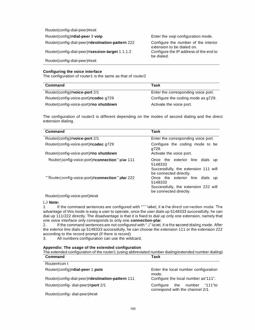
166
Router(config-dial-peer)#exit
Router(config)#dial-peer 3 voip Enter the voip configuration mode.
Router(config-dial-peer)#destination-pattern 222 Configure the number of the interior extension to be dialed on.
Router(config-dial-peer)#session-target 1.1.1.2 Configure the IP address of the end to be dialed.
Router(config-dial-peer)#exit
Configuring the voice interface The configuration of router1 is the same as that of router2
Command Task
Router(config)#voice-port 2/1 Enter the corresponding voice port.
Router(config-voice-port)#codec g729 Configure the coding mode as g729.
Router(config-voice-port)#no shutdown Activate the voice port.
The configuration of router3 is different depending on the modes of second dialing and the direct extension dialing.
Command Task
Router(config)#voice-port 2/1 Enter the corresponding voice port.
Router(config-voice-port)#codec g729 Configure the coding mode to be g729.
Router(config-voice-port)#no shutdown Activate the voice port.
�5RXWHU�FRQILJ-voice-port)#connection �SODU 111 Once the exterior line dials up 5148333 Successfully, the extension 111 will be connected directly.
�5RXWHU�FRQILJ-voice-port)#connection �Slar 222 Once the exterior line dials up 5148333 Successfully, the extension 222 will be connected directly.
Router(config-voice-port)#exit
Note: 1. If the command sentences are configured with “�´ ODEHO� LW LV WKH GLUHFW FRQQHFWLRQ PRGH� 7KH
advantage of this mode is easy a user to operate, once the user dials up 5148333 successfully, he can dial up 111/222 directly. The disadvantage is that it is fixed to dial up only one extension, namely that one voice interface only corresponds to only one connection-plar . 2. If the command sentences are not configured with “�´ ODEHO� LW LV WKH VHFRQG GLDOLQJ PRGH� $IWHU
the exterior line dials up 5148333 successfully, he can choose the extension 111 or the extension 222 according to the record prompt (if there is record) 3. All numbers configuration can use the wildcard. Appendix: The usage of the extended configuration The extended configuration of the router1 (using abbreviated number dialing/extended number dialing)
Command Task
Router#con t
Router(config)#dial-peer 1 pots Enter the local number configuration mode.
Router(config-dial-peer)#destination-pattern 111 Configure the local number as“111”.
Router(config- dial-peer)#port 2/1 Configure the number “111”to correspond with the channel 2/1.
Router(config- dial-peer)#exit
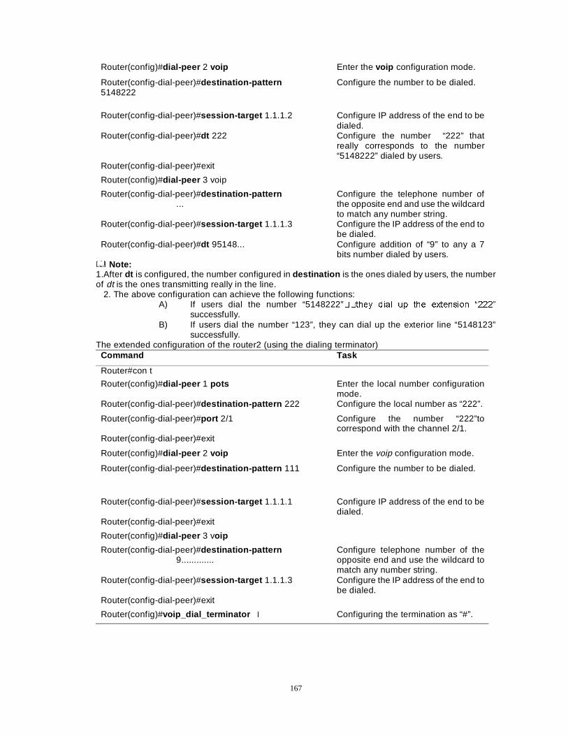
167
Router(config)#dial-peer 2 voip Enter the voip configuration mode.
Router(config-dial-peer)#destination-pattern 5148222
Configure the number to be dialed.
Router(config-dial-peer)#session-target 1.1.1.2 Configure IP address of the end to be dialed.
Router(config-dial-peer)#dt 222 Configure the number “222” that really corresponds to the number “5148222” dialed by users.
Router(config-dial-peer)#exit
Router(config)#dial-peer 3 voip
Router(config-dial-peer)#destination-pattern ...
Configure the telephone number of the opposite end and use the wildcard to match any number string.
Router(config-dial-peer)#session-target 1.1.1.3 Configure the IP address of the end to be dialed.
Router(config-dial-peer)#dt 95148... Configure addition of “9” to any a 7 bits number dialed by users.
Note: 1.After dt is configured, the number configured in destination is the ones dialed by users, the number of dt is the ones transmitting really in the line. 2. The above configuration can achieve the following functions:
A) If users dial the number “5148222”��WKH\ GLDO XS WKH H[WHQVLRQ ³���´
successfully. B) If users dial the number “123”, they can dial up the exterior line “5148123”
successfully. The extended configuration of the router2 (using the dialing terminator)
Command Task
Router#con t
Router(config)#dial-peer 1 pots Enter the local number configuration mode.
Router(config-dial-peer)#destination-pattern 222 Configure the local number as “222”.
Router(config-dial-peer)#port 2/1 Configure the number “222”to correspond with the channel 2/1.
Router(config-dial-peer)#exit
Router(config)#dial-peer 2 voip Enter the voip configuration mode.
Router(config-dial-peer)#destination-pattern 111 Configure the number to be dialed.
Router(config-dial-peer)#session-target 1.1.1.1 Configure IP address of the end to be dialed.
Router(config-dial-peer)#exit
Router(config)#dial-peer 3 voip
Router(config-dial-peer)#destination-pattern 9.............
Configure telephone number of the opposite end and use the wildcard to match any number string.
Router(config-dial-peer)#session-target 1.1.1.3 Configure the IP address of the end to be dialed.
Router(config-dial-peer)#exit
Router(config)#voip_dial_terminator � Configuring the termination as “#”.
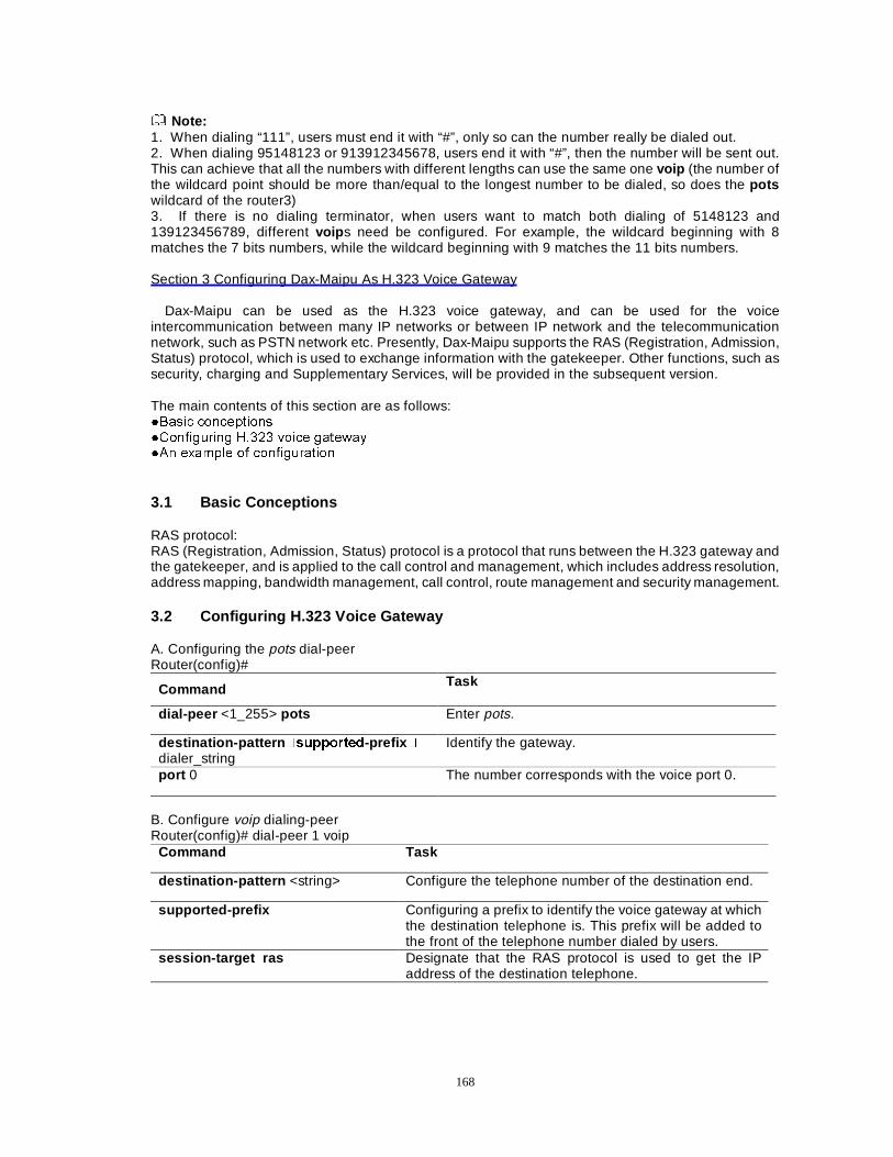
168
Note: 1. When dialing “111”, users must end it with “#”, only so can the number really be dialed out. 2. When dialing 95148123 or 913912345678, users end it with “#”, then the number will be sent out. This can achieve that all the numbers with different lengths can use the same one voip (the number of the wildcard point should be more than/equal to the longest number to be dialed, so does the pots wildcard of the router3) 3. If there is no dialing terminator, when users want to match both dialing of 5148123 and 139123456789, different voip s need be configured. For example, the wildcard beginning with 8 matches the 7 bits numbers, while the wildcard beginning with 9 matches the 11 bits numbers. Section 3 Configuring Dax-Maipu As H.323 Voice Gateway
Dax-Maipu can be used as the H.323 voice gateway, and can be used for the voice intercommunication between many IP networks or between IP network and the telecommunication network, such as PSTN network etc. Presently, Dax-Maipu supports the RAS (Registration, Admission, Status) protocol, which is used to exchange information with the gatekeeper. Other functions, such as security, charging and Supplementary Services, will be provided in the subsequent version. The main contents of this section are as follows: �%DVLF FRQFHSWLRQV �&RQILJXULQJ +���� YRLFH JDWHZD\ �$Q H[DPSOH RI FRQILJXUDWLRQ 3.1 Basic Conceptions RAS protocol: RAS (Registration, Admission, Status) protocol is a protocol that runs between the H.323 gateway and the gatekeeper, and is applied to the call control and management, which includes address resolution, address mapping, bandwidth management, call control, route management and security management. 3.2 Configuring H.323 Voice Gateway A. Configuring the pots dial-peer Router(config)#
Command Task
dial-peer <1_255> pots Enter pots.
destination-pattern �VXSSRUWHG-prefix �
dialer_string Identify the gateway.
port 0 The number corresponds with the voice port 0.
B. Configure voip dialing-peer Router(config)# dial-peer 1 voip
Command Task
destination-pattern <string> Configure the telephone number of the destination end.
supported-prefix Configuring a prefix to identify the voice gateway at which the destination telephone is. This prefix will be added to the front of the telephone number dialed by users.
session-target ras Designate that the RAS protocol is used to get the IP address of the destination telephone.
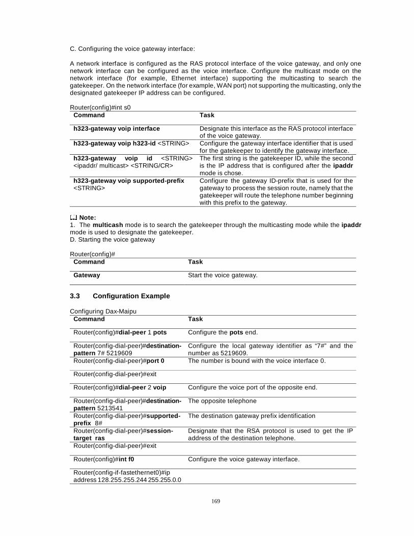
169
C. Configuring the voice gateway interface: A network interface is configured as the RAS protocol interface of the voice gateway, and only one network interface can be configured as the voice interface. Configure the multicast mode on the network interface (for example, Ethernet interface) supporting the multicasting to search the gatekeeper. On the network interface (for example, WAN port) not supporting the multicasting, only the designated gatekeeper IP address can be configured. Router(config)#int s0
Command Task
h323-gateway voip interface Designate this interface as the RAS protocol interface of the voice gateway.
h323-gateway voip h323-id <STRING> Configure the gateway interface identifier that is used for the gatekeeper to identify the gateway interface.
h323-gateway voip id <STRING> <ipaddr/ multicast> <STRING/CR>
The first string is the gatekeeper ID, while the second is the IP address that is configured after the ipaddr mode is chose.
h323-gateway voip supported-prefix <STRING>
Configure the gateway ID-prefix that is used for the gateway to process the session route, namely that the gatekeeper will route the telephone number beginning with this prefix to the gateway.
Note: 1. The multicash mode is to search the gatekeeper through the multicasting mode while the ipaddr mode is used to designate the gatekeeper. D. Starting the voice gateway Router(config)#
Command Task
Gateway Start the voice gateway.
3.3 Configuration Example Configuring Dax-Maipu
Command Task
Router(config)#dial-peer 1 pots Configure the pots end.
Router(config-dial-peer)#destination-pattern 7# 5219609
Configure the local gateway identifier as “7#” and the number as 5219609.
Router(config-dial-peer)#port 0 The number is bound with the voice interface 0.
Router(config-dial-peer)#exit
Router(config)#dial-peer 2 voip Configure the voice port of the opposite end.
Router(config-dial-peer)#destination-pattern 5213541
The opposite telephone
Router(config-dial-peer)#supported-prefix 8#
The destination gateway prefix identification
Router(config-dial-peer)#session-target ras
Designate that the RSA protocol is used to get the IP address of the destination telephone.
Router(config-dial-peer)#exit
Router(config)#int f0 Configure the voice gateway interface.
Router(config-if-fastethernet0)#ip address 128.255.255.244 255.255.0.0
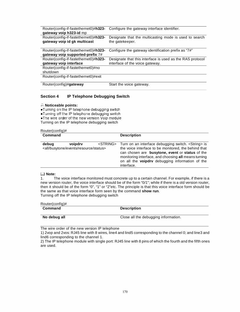
170
Router(config-if-fastethernet0)#h323-gateway voip h323-id mp
Configure the gateway interface identifier.
Router(config-if-fastethernet0)#h323-gateway voip id gk multicast
Designate that the multicasting mode is used to search the gatekeeper.
Router(config-if-fastethernet0)#h323-gateway voip supported-prefix 7#
Configure the gateway identification prefix as “7#”
Router(config-if-fastethernet0)#h323-gateway voip interface
Designate that this interface is used as the RAS protocol interface of the voice gateway.
Router(config-if-fastethernet0)#no shutdown
Router(config-if-fastethernet0)#exit
Router(config)#gateway Start the voice gateway.
Section 4 IP Telephone Debugging Switch � Noticeable points: �7XUQLQJ RQ WKH ,3 WHOHSKRQH GHEXJJLQJ VZLWFK �7XUQLQJ RII WKH ,3 WHOHSKRQH GHEXJJLQJ VZLWFK �7KH ZLUH RUGHU RI WKH QHZ YHUVLRQ 9RLS PRGXOH Turning on the IP telephone debugging switch Router(config)#
Command Description
debug voipdrv <STRING> <all/busytone/events/resource/status>
Turn on an interface debugging switch. <String> is the voice interface to be monitored, the behind that can chosen are busytone, event or status of the monitoring interface, and choosing all means turning on all the voipdrv debugging information of the interface.
Note: 1. The voice interface monitored must concrete up to a certain channel. For example, if there is a new version router, the voice interface should be of the form “0/1”; while if there is a old version router, then it should be of the form “0”, “1” or “2”etc. The principle is that this voice interface form should be the same as that voice interface form seen by the command show run . Turning off the IP telephone debugging switch Router(config)#
Command Description
No debug all Close all the debugging information.
The wire order of the new version IP telephone 1) 2vop and 2vos: RJ45 line with 8 wires, line4 and lind5 corresponding to the channel 0; and line3 and lind6 corresponding to the channel 1. 2) The IP telephone module with single port: RJ45 line with 8 pins of which the fourth and the fifth ones are used.
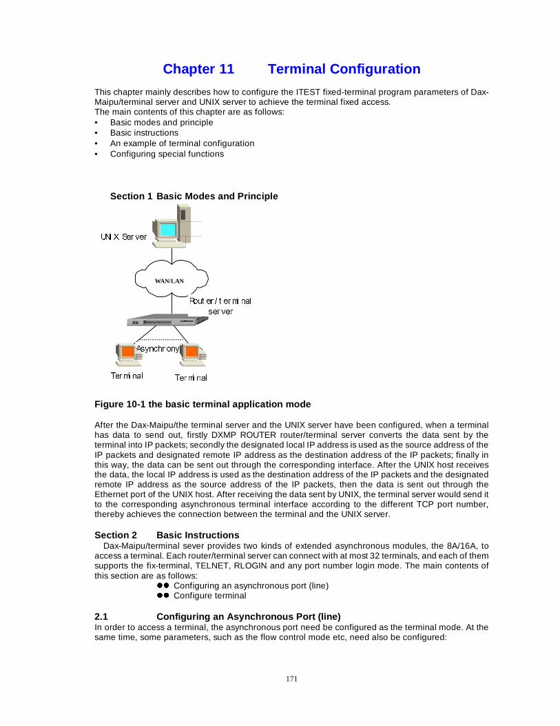
171
Chapter 11 Terminal Configuration This chapter mainly describes how to configure the ITEST fixed-terminal program parameters of Dax-Maipu/terminal server and UNIX server to achieve the terminal fixed access. The main contents of this chapter are as follows: • Basic modes and principle • Basic instructions • An example of terminal configuration • Configuring special functions
Section 1 Basic Modes and Principle
WAN/LAN
81, ; 6HU YHU
5RXW HU � W HUPL QDO
VHU YHU
7HUPL QDO 7HUPL QDO
$V\QFKU RQ\
Figure 10-1 the basic terminal application mode After the Dax-Maipu/the terminal server and the UNIX server have been configured, when a terminal has data to send out, firstly DXMP ROUTER router/terminal server converts the data sent by the terminal into IP packets; secondly the designated local IP address is used as the source address of the IP packets and designated remote IP address as the destination address of the IP packets; finally in this way, the data can be sent out through the corresponding interface. After the UNIX host receives the data, the local IP address is used as the destination address of the IP packets and the designated remote IP address as the source address of the IP packets, then the data is sent out through the Ethernet port of the UNIX host. After receiving the data sent by UNIX, the terminal server would send it to the corresponding asynchronous terminal interface according to the different TCP port number, thereby achieves the connection between the terminal and the UNIX server. Section 2 Basic Instructions
Dax-Maipu/terminal sever provides two kinds of extended asynchronous modules, the 8A/16A, to access a terminal. Each router/terminal server can connect with at most 32 terminals, and each of them supports the fix-terminal, TELNET, RLOGIN and any port number login mode. The main contents of this section are as follows:
zz Configuring an asynchronous port (line) zz Configure terminal
2.1 Configuring an Asynchronous Port (line) In order to access a terminal, the asynchronous port need be configured as the terminal mode. At the same time, some parameters, such as the flow control mode etc, need also be configured:
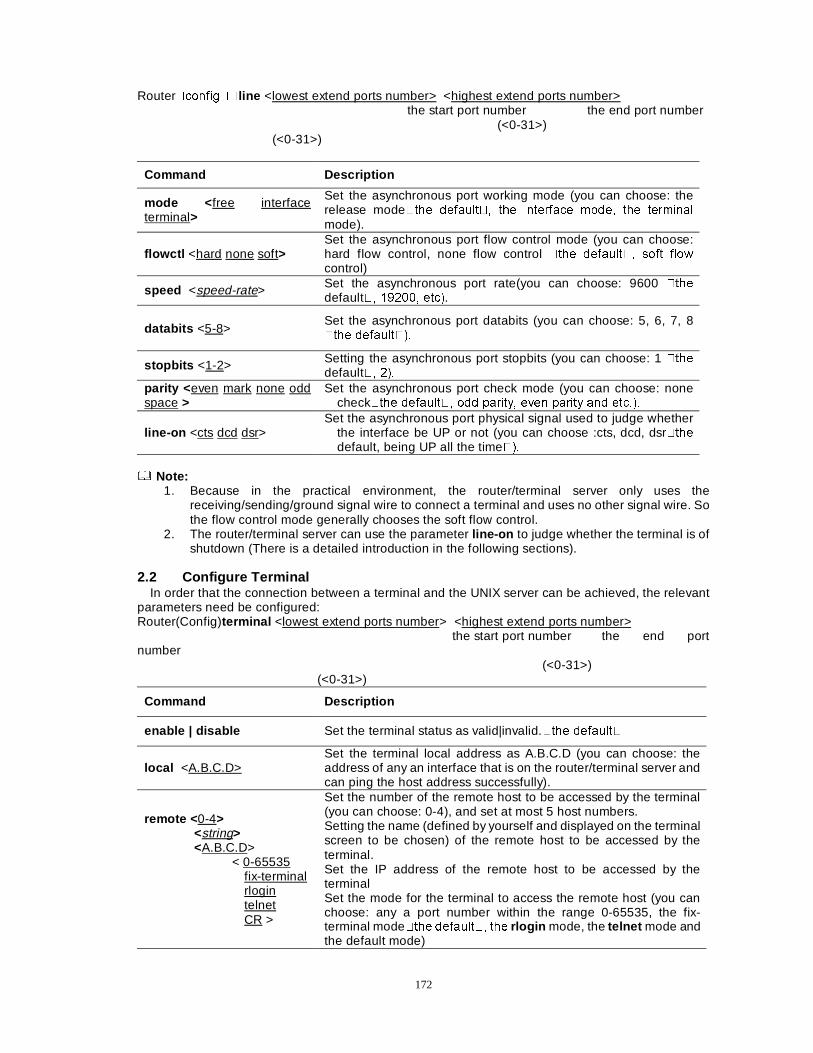
172
Router�FRQILJ��line <lowest extend ports number> <highest extend ports number> the start port number the end port number (<0-31>) (<0-31>)
Command Description
mode < free interface terminal>
Set the asynchronous port working mode (you can choose: the release mode�WKH GHIDXOW�� WKH LQWHUIDFH PRGH� WKH WHUPLQDO
mode).
flowctl <hard none soft> Set the asynchronous port flow control mode (you can choose: hard flow control, none flow control �WKH GHIDXOW�� VRIW IORZ
control)
speed <speed-rate> Set the asynchronous port rate(you can choose: 9600 �WKH
default�� ������ HWF�.
databits <5-8> Set the asynchronous port databits (you can choose: 5, 6, 7, 8 �WKH GHIDXOW���
stopbits <1-2> Setting the asynchronous port stopbits (you can choose: 1 �WKH
default�� ��� parity < even mark none odd space >
Set the asynchronous port check mode (you can choose: none check�WKH GHIDXOW�� RGG SDULW\� HYHQ SDULW\ DQG HWF���
line-on <cts dcd dsr> Set the asynchronous port physical signal used to judge whether
the interface be UP or not (you can choose :cts, dcd, dsr�WKH
default, being UP all the time��� Note:
1. Because in the practical environment, the router/terminal server only uses the receiving/sending/ground signal wire to connect a terminal and uses no other signal wire. So the flow control mode generally chooses the soft flow control.
2. The router/terminal server can use the parameter line-on to judge whether the terminal is of shutdown (There is a detailed introduction in the following sections).
2.2 Configure Terminal
In order that the connection between a terminal and the UNIX server can be achieved, the relevant parameters need be configured: Router(Config)terminal <lowest extend ports number> <highest extend ports number> the start port number the end port number (<0-31>) (<0-31>)
Command Description
enable | disable Set the terminal status as valid|invalid.�WKH GHIDXOW�
local <A.B.C.D> Set the terminal local address as A.B.C.D (you can choose: the address of any an interface that is on the router/terminal server and can ping the host address successfully).
remote < 0-4> <string> <A.B.C.D>
< 0-65535 fix-terminal rlogin telnet CR >
Set the number of the remote host to be accessed by the terminal (you can choose: 0-4), and set at most 5 host numbers. Setting the name (defined by yourself and displayed on the terminal screen to be chosen) of the remote host to be accessed by the terminal. Set the IP address of the remote host to be accessed by the terminal Set the mode for the terminal to access the remote host (you can choose: any a port number within the range 0-65535, the fix-terminal mode�WKH GHIDXOW�� WKH rlogin mode, the telnet mode and the default mode)
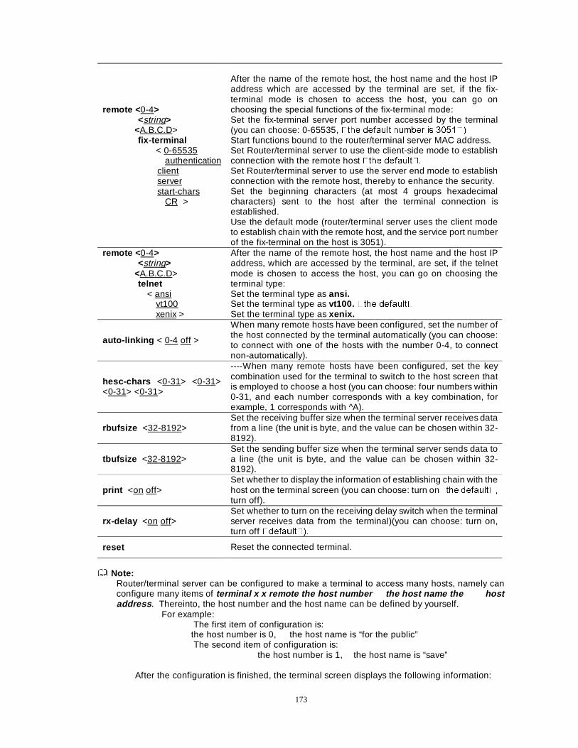
173
remote < 0-4> <string>
<A.B.C.D> fix-terminal
< 0-65535 authentication
client server start-chars
CR >
After the name of the remote host, the host name and the host IP address which are accessed by the terminal are set, if the fix-terminal mode is chosen to access the host, you can go on choosing the special functions of the fix-terminal mode: Set the fix-terminal server port number accessed by the terminal (you can choose: 0-65535, �WKH GHIDXOW QXPEHU LV ������ Start functions bound to the router/terminal server MAC address. Set Router/terminal server to use the client-side mode to establish connection with the remote host �WKH GHIDXOW�� Set Router/terminal server to use the server end mode to establish connection with the remote host, thereby to enhance the security. Set the beginning characters (at most 4 groups hexadecimal characters) sent to the host after the terminal connection is established. Use the default mode (router/terminal server uses the client mode to establish chain with the remote host, and the service port number of the fix-terminal on the host is 3051).
remote < 0-4> <string>
<A.B.C.D> telnet
< ansi vt100 xenix >
After the name of the remote host, the host name and the host IP address, which are accessed by the terminal, are set, if the telnet mode is chosen to access the host, you can go on choosing the terminal type: Set the terminal type as ansi. Set the terminal type as vt100. �WKH GHIDXOW� Set the terminal type as xenix.
auto-linking < 0-4 off >
When many remote hosts have been configured, set the number of the host connected by the terminal automatically (you can choose: to connect with one of the hosts with the number 0-4, to connect non-automatically).
hesc-chars <0-31> <0-31> <0-31> <0-31>
----When many remote hosts have been configured, set the key combination used for the terminal to switch to the host screen that is employed to choose a host (you can choose: four numbers within 0-31, and each number corresponds with a key combination, for example, 1 corresponds with ^A).
rbufsize <32-8192> Set the receiving buffer size when the terminal server receives data from a line (the unit is byte, and the value can be chosen within 32-8192).
tbufsize <32-8192> Set the sending buffer size when the terminal server sends data to a line (the unit is byte, and the value can be chosen within 32-8192).
print <on off> Set whether to display the information of establishing chain with the host on the terminal screen (you can choose: turn on�WKH GHIDXOW��
turn off).
rx-delay <on off> Set whether to turn on the receiving delay switch when the terminal server receives data from the terminal)(you can choose: turn on, turn off �GHIDXOW���
reset Reset the connected terminal.
Note:
Router/terminal server can be configured to make a terminal to access many hosts, namely can configure many items of terminal x x remote the host number the host name the host address . Thereinto, the host number and the host name can be defined by yourself.
For example: The first item of configuration is:
the host number is 0, the host name is “for the public” The second item of configuration is: the host number is 1, the host name is “save”
After the configuration is finished, the terminal screen displays the following information:
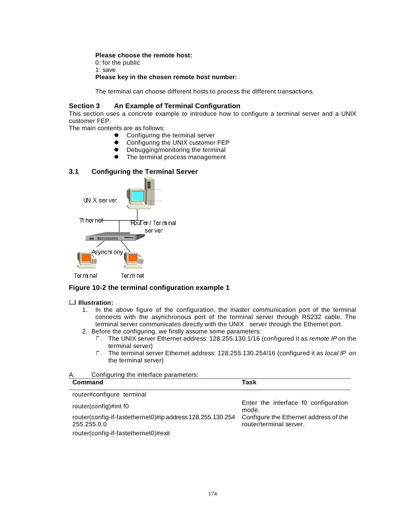
174
Please choose the remote host: 0: for the public 1: save Please key in the chosen remote host number: The terminal can choose different hosts to process the different transactions.
Section 3 An Example of Terminal Configuration This section uses a concrete example to introduce how to configure a terminal server and a UNIX customer FEP. The main contents are as follows:
z Configuring the terminal server z Configuring the UNIX customer FEP z Debugging/monitoring the terminal z The terminal process management
3.1 Configuring the Terminal Server
81, ; VHU YHU
5RXW HU � 7HUPL QDO
VHU YHU
7HUPL QDO 7HUPL QDO
$V\QFKU RQ\
7W KHU QHW
Figure 10-2 the terminal configuration example 1 Illustration:
1. In the above figure of the configuration, the master communication port of the terminal connects with the asynchronous port of the terminal server through RS232 cable. The terminal server communicates directly with the UNIX server through the Ethernet port.
2. Before the configuring, we firstly assume some parameters: �� The UNIX server Ethernet address: 128.255.130.1/16 (configured it as remote IP on the
terminal server) �� The terminal server Ethernet address: 128.255.130.254/16 (configured it as local IP on
the terminal server) A. Configuring the interface parameters:
Command Task
router#configure terminal
router(config)#int f0 Enter the interface f0 configuration mode.
router(config-if-fastethernet0)#ip address 128.255.130.254 255.255.0.0
Configure the Ethernet address of the router/terminal server.
router(config-if-fastethernet0)#exit
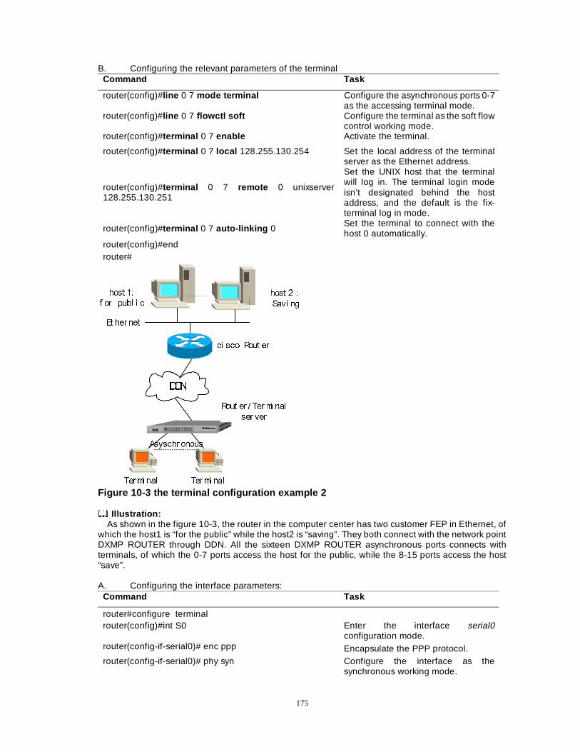
175
B. Configuring the relevant parameters of the terminal Command Task
router(config)#line 0 7 mode terminal Configure the asynchronous ports 0-7 as the accessing terminal mode.
router(config)#line 0 7 flowctl soft Configure the terminal as the soft flow control working mode.
router(config)#terminal 0 7 enable Activate the terminal.
router(config)#terminal 0 7 local 128.255.130.254 Set the local address of the terminal server as the Ethernet address.
router(config)#terminal 0 7 remote 0 unixserver 128.255.130.251
Set the UNIX host that the terminal will log in. The terminal login mode isn’t designated behind the host address, and the default is the fix-terminal log in mode.
router(config)#terminal 0 7 auto-linking 0 Set the terminal to connect with the host 0 automatically.
router(config)#end router#
$V\VFKU RQRXV
''1
KRVW ��
I RU SXEO L F
7HUPL QDO
5RXW HU � 7HUPL QDO
VHU YHU
7HUPL QDO
KRVW �Û
6DYL QJ
FL VFR 5RXW HU
(W KHU QHW
Figure 10-3 the terminal configuration example 2 Illustration:
As shown in the figure 10-3, the router in the computer center has two customer FEP in Ethernet, of which the host1 is “for the public” while the host2 is “saving”. They both connect with the network point DXMP ROUTER through DDN. All the sixteen DXMP ROUTER asynchronous ports connects with terminals, of which the 0-7 ports access the host for the public, while the 8-15 ports access the host “save”.
A. Configuring the interface parameters:
Command Task
router#configure terminal router(config)#int S0 Enter the interface serial0
configuration mode. router(config-if-serial0)# enc ppp Encapsulate the PPP protocol. router(config-if-serial0)# phy syn Configure the interface as the
synchronous working mode.
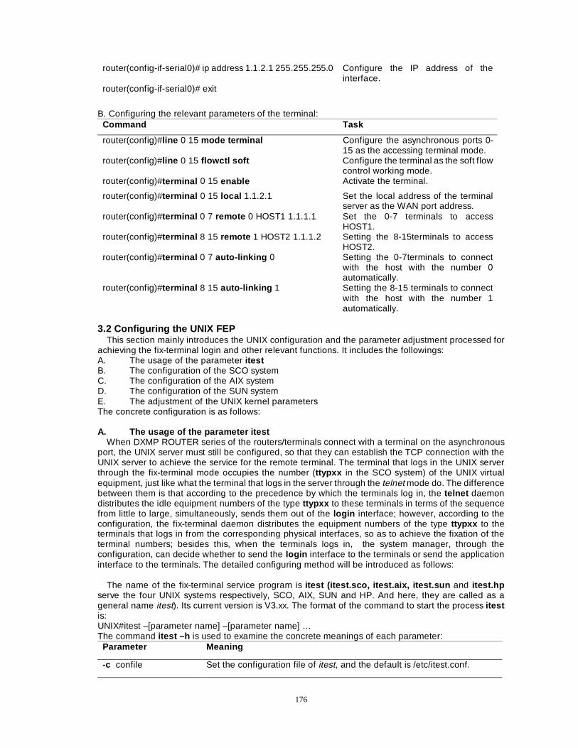
176
router(config-if-serial0)# ip address 1.1.2.1 255.255.255.0 Configure the IP address of the interface.
router(config-if-serial0)# exit B. Configuring the relevant parameters of the terminal:
Command Task
router(config)#line 0 15 mode terminal Configure the asynchronous ports 0-15 as the accessing terminal mode.
router(config)#line 0 15 flowctl soft Configure the terminal as the soft flow control working mode.
router(config)#terminal 0 15 enable Activate the terminal.
router(config)#terminal 0 15 local 1.1.2.1 Set the local address of the terminal server as the WAN port address.
router(config)#terminal 0 7 remote 0 HOST1 1.1.1.1 Set the 0-7 terminals to access HOST1.
router(config)#terminal 8 15 remote 1 HOST2 1.1.1.2 Setting the 8-15terminals to access HOST2.
router(config)#terminal 0 7 auto-linking 0 Setting the 0-7terminals to connect with the host with the number 0 automatically.
router(config)#terminal 8 15 auto-linking 1 Setting the 8-15 terminals to connect with the host with the number 1 automatically.
3.2 Configuring the UNIX FEP
This section mainly introduces the UNIX configuration and the parameter adjustment processed for achieving the fix-terminal login and other relevant functions. It includes the followings: A. The usage of the parameter itest B. The configuration of the SCO system C. The configuration of the AIX system D. The configuration of the SUN system E. The adjustment of the UNIX kernel parameters The concrete configuration is as follows: A. The usage of the parameter itest
When DXMP ROUTER series of the routers/terminals connect with a terminal on the asynchronous port, the UNIX server must still be configured, so that they can establish the TCP connection with the UNIX server to achieve the service for the remote terminal. The terminal that logs in the UNIX server through the fix-terminal mode occupies the number (ttypxx in the SCO system) of the UNIX virtual equipment, just like what the terminal that logs in the server through the telnet mode do. The difference between them is that according to the precedence by which the terminals log in, the telnet daemon distributes the idle equipment numbers of the type ttypxx to these terminals in terms of the sequence from little to large, simultaneously, sends them out of the login interface; however, according to the configuration, the fix-terminal daemon distributes the equipment numbers of the type ttypxx to the terminals that logs in from the corresponding physical interfaces, so as to achieve the fixation of the terminal numbers; besides this, when the terminals logs in, the system manager, through the configuration, can decide whether to send the login interface to the terminals or send the application interface to the terminals. The detailed configuring method will be introduced as follows:
The name of the fix-terminal service program is itest (itest.sco, itest.aix, itest.sun and itest.hp serve the four UNIX systems respectively, SCO, AIX, SUN and HP. And here, they are called as a general name itest). Its current version is V3.xx. The format of the command to start the process itest is: UNIX#itest –[parameter name] –[parameter name] … The command itest –h is used to examine the concrete meanings of each parameter:
Parameter Meaning
-c confile Set the configuration file of itest, and the default is /etc/itest.conf.
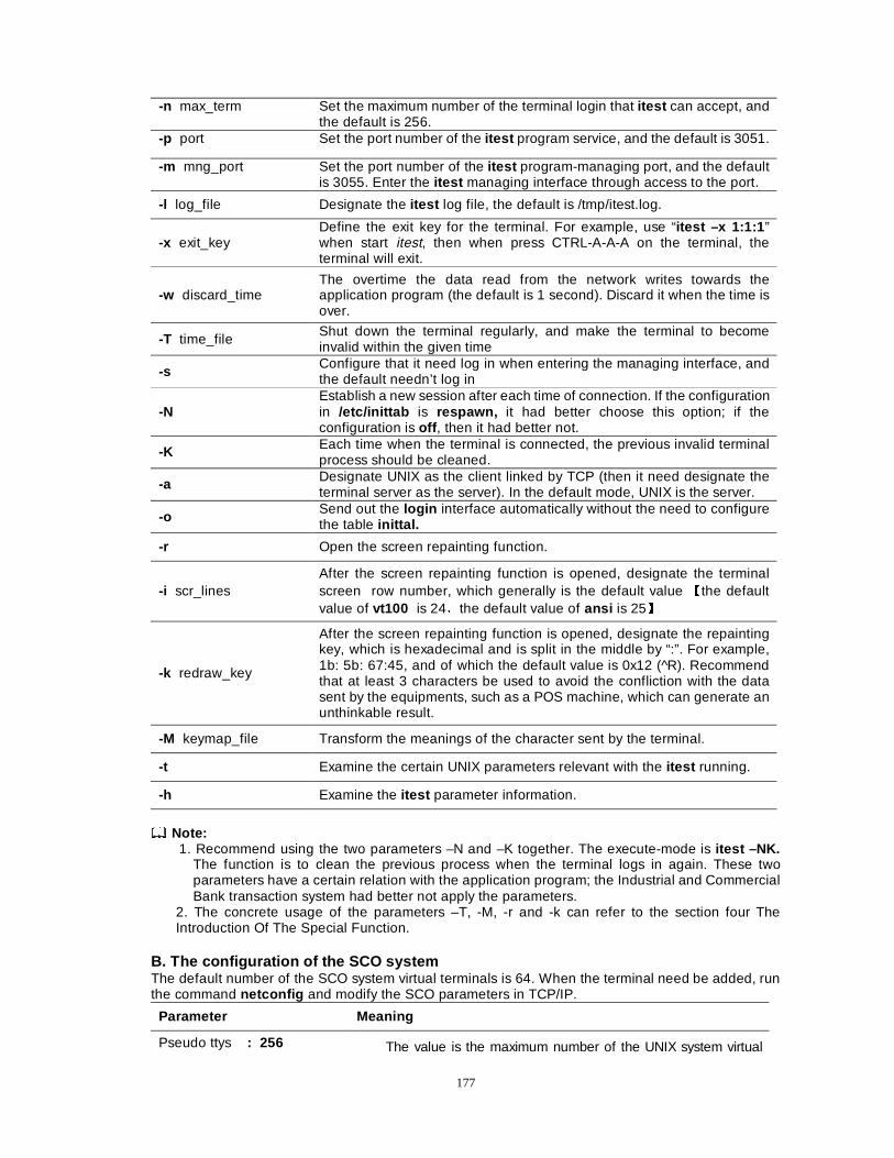
177
-n max_term Set the maximum number of the terminal login that itest can accept, and the default is 256.
-p port Set the port number of the itest program service, and the default is 3051.
-m mng_port Set the port number of the itest program-managing port, and the default is 3055. Enter the itest managing interface through access to the port.
-l log_file Designate the itest log file, the default is /tmp/itest.log.
-x exit_key Define the exit key for the terminal. For example, use “itest –x 1:1:1 ” when start itest, then when press CTRL-A-A-A on the terminal, the terminal will exit.
-w discard_time The overtime the data read from the network writes towards the application program (the default is 1 second). Discard it when the time is over.
-T time_file Shut down the terminal regularly, and make the terminal to become invalid within the given time
-s Configure that it need log in when entering the managing interface, and the default needn’t log in
-N Establish a new session after each time of connection. If the configuration in /etc/inittab is respawn, it had better choose this option; if the configuration is off , then it had better not.
-K Each time when the terminal is connected, the previous invalid terminal process should be cleaned.
-a Designate UNIX as the client linked by TCP (then it need designate the terminal server as the server). In the default mode, UNIX is the server.
-o Send out the login interface automatically without the need to configure the table inittal.
-r Open the screen repainting function.
-i scr_lines After the screen repainting function is opened, designate the terminal screen row number, which generally is the default value Ïthe default value of vt100 is 24Èthe default value of ansi is 25Ð
-k redraw_key
After the screen repainting function is opened, designate the repainting key, which is hexadecimal and is split in the middle by “:”. For example, 1b: 5b: 67:45, and of which the default value is 0x12 (^R). Recommend that at least 3 characters be used to avoid the confliction with the data sent by the equipments, such as a POS machine, which can generate an unthinkable result.
-M keymap_file Transform the meanings of the character sent by the terminal.
-t Examine the certain UNIX parameters relevant with the itest running.
-h Examine the itest parameter information.
Note:
1. Recommend using the two parameters –N and –K together. The execute-mode is itest –NK. The function is to clean the previous process when the terminal logs in again. These two parameters have a certain relation with the application program; the Industrial and Commercial Bank transaction system had better not apply the parameters.
2. The concrete usage of the parameters –T, -M, -r and -k can refer to the section four The Introduction Of The Special Function.
B. The configuration of the SCO system The default number of the SCO system virtual terminals is 64. When the terminal need be added, run the command netconfig and modify the SCO parameters in TCP/IP.
Parameter Meaning
Pseudo ttys : 256 The value is the maximum number of the UNIX system virtual
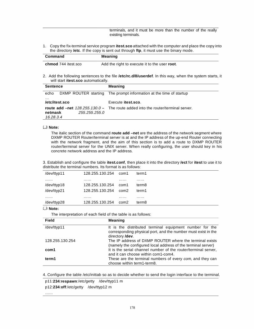
178
terminals, and it must be more than the number of the really existing terminals.
1. Copy the fix-terminal service program itest.sco attached with the computer and place the copy into the directory /etc . If the copy is sent out through ftp , it must use the binary mode.
Command Meaning
chmod 744 itest.sco Add the right to execute it to the user root .
2. Add the following sentences to the file /etc/rc.d/8/userdef . In this way, when the system starts, it
will start itest.sco automatically.
Sentence Meaning
echo DXMP ROUTER starting …
The prompt information at the time of startup
/etc/itest.sco Execute itest.sco .
route add –net 128.255.130.0 –netmask 255.255.255.0 16.28.3.4
The route added into the router/terminal server.
Note:
The italic section of the command route add –net are the address of the network segment where DXMP ROUTER Router/terminal server is at and the IP address of the up-end Router connecting with the network fragment, and the aim of this section is to add a route to DXMP ROUTER router/terminal server for the UNIX server. When really configuring, the user should key in his concrete network address and the IP address.
3. Establish and configure the table itest.conf , then place it into the directory /ect for itest to use it to distribute the terminal numbers. Its format is as follows:
/dev/ttyp11 128.255.130.254 com1 term1
…… …… …… ……
/dev/ttyp18 128.255.130.254 com1 term8
/dev/ttyp21 128.255.130.254 com2 term1
…… …… …… ……
/dev/ttyp28 128.255.130.254 com2 term8
Note: The interpretation of each field of the table is as follows:
Field Meaning
/dev/ttyp11 It is the distributed terminal equipment number for the corresponding physical port, and the number must exist in the directory /dev .
128.255.130.254 The IP address of DXMP ROUTER where the terminal exists (namely the configured local address of the terminal server)
com1 It is the serial channel number of the router/terminal server, and it can choose within com1-com4.
term1 These are the terminal numbers of every com, and they can choose within term1-term8.
4. Configure the table /etc/inittab so as to decide whether to send the login interface to the terminal.
p11:234:respawn :/etc/getty /dev/ttyp11 m p12:234:off :/etc/getty /dev/ttyp12 m
……
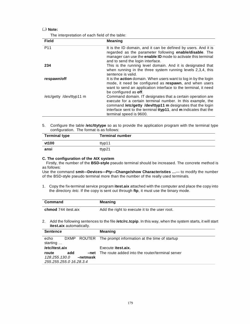
179
Note:
The interpretation of each field of the table:
Field Meaning
P11 It is the ID domain, and it can be defined by users. And it is regarded as the parameter following enable/disable . The manager can use the enable ID mode to activate this terminal and to send the login interface.
234 This is the running level domain. And it is designated that when running in the three system running levels 2,3,4, this sentence is valid.
respawn/off It is the action domain. When users want to log in by the login mode, it need be configured as respawn , and when users want to send an application interface to the terminal, it need be configured as off .
/etc/getty /dev/ttyp11 m Command domain. IT designates that a certain operation are execute for a certain terminal number. In this example, the command /etc/getty /dev/ttyp11 m designates that the login interface sent to the terminal ttyp11 , and m indicates that the terminal speed is 9600.
5. Configure the table /etc/ttytype so as to provide the application program with the terminal type configuration. The format is as follows:
Terminal type Terminal number
vt100 ttyp11
ansi ttyp21 C. The configuration of the AIX system
Firstly, the number of the BSD-style pseudo terminal should be increased. The concrete method is as follows: Use the command smit—Devices—Pty—Change/show Characteristies … — to modify the number of the BSD-style pseudo terminal more than the number of the really used terminals.
1. Copy the fix-terminal service program itest.aix attached with the computer and place the copy into the directory /etc. If the copy is sent out through ftp , it must use the binary mode.
Command Meaning
chmod 744 itest.aix Add the right to execute it to the user root.
2. Add the following sentences to the file /etc/rc.tcpip . In this way, when the system starts, it will start itest.aix automatically.
Sentence Meaning
echo DXMP ROUTER starting …
The prompt information at the time of startup
/etc/itest.aix Execute itest.aix. route add –net 128.255.130.0 –netmask 255.255.255.0 16.28.3.4
The route added into the router/terminal server
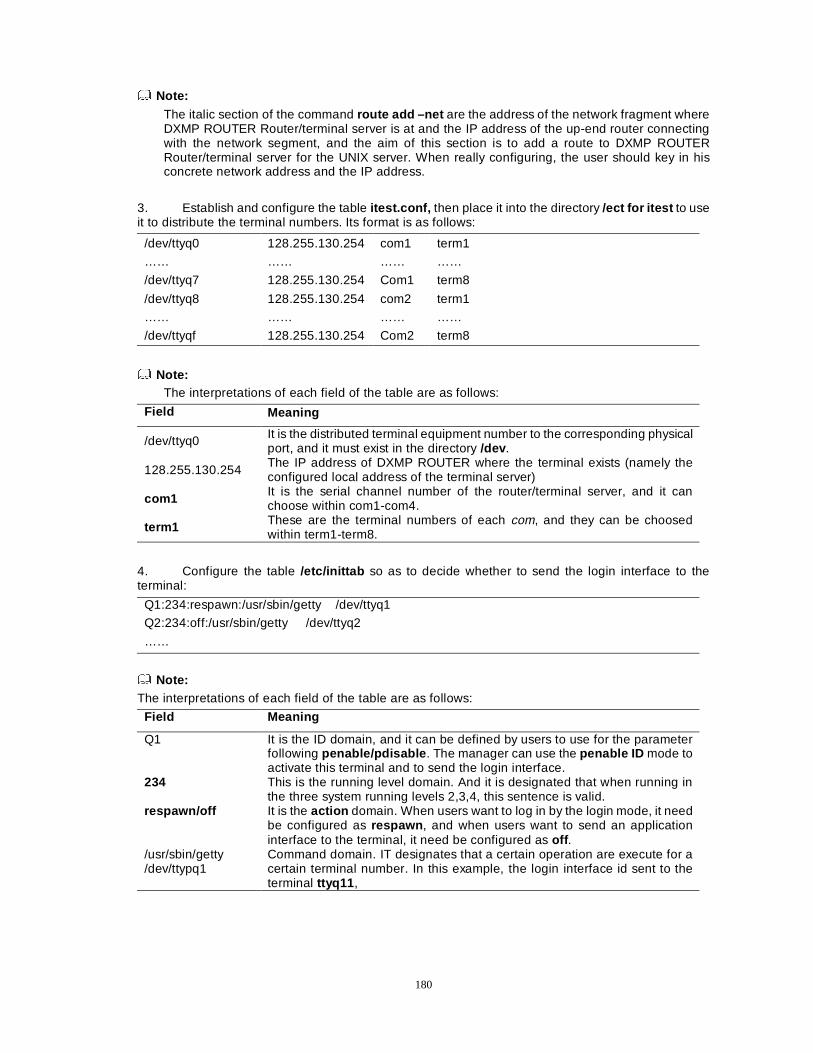
180
Note: The italic section of the command route add –net are the address of the network fragment where DXMP ROUTER Router/terminal server is at and the IP address of the up-end router connecting with the network segment, and the aim of this section is to add a route to DXMP ROUTER Router/terminal server for the UNIX server. When really configuring, the user should key in his concrete network address and the IP address.
3. Establish and configure the table itest.conf, then place it into the directory /ect for itest to use it to distribute the terminal numbers. Its format is as follows:
/dev/ttyq0 128.255.130.254 com1 term1
…… …… …… ……
/dev/ttyq7 128.255.130.254 Com1 term8
/dev/ttyq8 128.255.130.254 com2 term1
…… …… …… ……
/dev/ttyqf 128.255.130.254 Com2 term8
Note: The interpretations of each field of the table are as follows:
Field Meaning
/dev/ttyq0 It is the distributed terminal equipment number to the corresponding physical port, and it must exist in the directory /dev .
128.255.130.254 The IP address of DXMP ROUTER where the terminal exists (namely the configured local address of the terminal server)
com1 It is the serial channel number of the router/terminal server, and it can choose within com1-com4.
term1 These are the terminal numbers of each com, and they can be choosed within term1-term8.
4. Configure the table /etc/inittab so as to decide whether to send the login interface to the terminal:
Q1:234:respawn:/usr/sbin/getty /dev/ttyq1
Q2:234:off:/usr/sbin/getty /dev/ttyq2
……
Note:
The interpretations of each field of the table are as follows:
Field Meaning
Q1 It is the ID domain, and it can be defined by users to use for the parameter following penable/pdisable . The manager can use the penable ID mode to activate this terminal and to send the login interface.
234 This is the running level domain. And it is designated that when running in the three system running levels 2,3,4, this sentence is valid.
respawn/off It is the action domain. When users want to log in by the login mode, it need be configured as respawn , and when users want to send an application interface to the terminal, it need be configured as off .
/usr/sbin/getty /dev/ttypq1
Command domain. IT designates that a certain operation are execute for a certain terminal number. In this example, the login interface id sent to the terminal ttyq11 ,
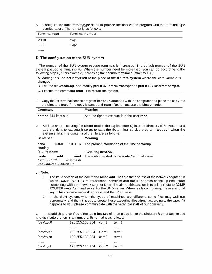
181
5. Configure the table /etc/ttytype so as to provide the application program with the terminal type configuration. The format is as follows:
Terminal type Terminal number
vt100 ttyq1
ansi ttyq2
……
D. The configuration of the SUN system
The number of the SUN system pseudo terminals is increased. The default number of the SUN system pseudo terminals is 48. When the number need be increased, you can do according to the following steps (in this example, increasing the pseudo terminal number to 128):
A. Adding this line set npty=128 at the place of the file /etc/system where the core variable is changed. B. Edit the file /etc/iu.ap , and modify ptsl 0 47 ldterm ttcompat as ptsl 0 127 ldterm ttcompat.
C. Execute the command boot –r to restart the system.
1. Copy the fix-terminal service program itest.sun attached with the computer and place the copy into the directory /etc . If the copy is sent out through ftp , it must use the binary mode.
Command Meaning
chmod 744 itest.sun Add the right to execute it to the user root .
2. Add a startup executing file Sitest (notice the capital letter S) into the directory of /etc/rc3.d, and add the right to execute it so as to start the fix-terminal service program itest.sun when the system starts. The contents of the file are as follows:
Sentense Meaning
echo DXMP ROUTER starting …
The prompt information at the time of startup
/etc/itest.sun Executing itest.aix. route add –net 128.255.130.0 –netmask 255.255.255.0 16.28.3.4
The routing added to the router/terminal server
Note:
1. The italic section of the command route add –net are the address of the network segment in which DXMP ROUTER router/terminal server is and the IP address of the up-end router connecting with the network segment, and the aim of this section is to add a route to DXMP ROUTER router/terminal server for the UNIX server. When really configuring, the user should key in his concrete network address and the IP address.
2. In the SUN system, when the types of machines are different, some files may well run abnormally, and then it needs to create these executing files afresh according to the type. If it happens to you, please communicate with the technical staff of our company.
3. Establish and configure the table itest.conf , then place it into the directory /ect for itest to use it to distribute the terminal numbers. Its format is as follows:
/dev/ttyq0 128.255.130.254 com1 term1
…… …… …… ……
/dev/ttyq7 128.255.130.254 Com1 term8
/dev/ttyq8 128.255.130.254 com2 term1
…… …… …… ……
/dev/ttyqf 128.255.130.254 Com2 term8
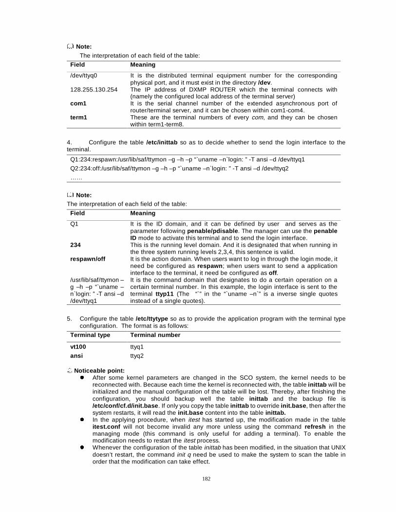
182
Note: The interpretation of each field of the table:
Field Meaning
/dev/ttyq0 It is the distributed terminal equipment number for the corresponding physical port, and it must exist in the directory /dev .
128.255.130.254 The IP address of DXMP ROUTER which the terminal connects with (namely the configured local address of the terminal server)
com1 It is the serial channel number of the extended asynchronous port of router/terminal server, and it can be chosen within com1-com4.
term1 These are the terminal numbers of every com, and they can be chosen within term1-term8.
4. Configure the table /etc/inittab so as to decide whether to send the login interface to the terminal.
Q1:234:respawn:/usr/lib/saf/ttymon –g –h –p “`uname –n`login: ” -T ansi –d /dev/ttyq1 Q2:234:off:/usr/lib/saf/ttymon –g –h –p “`uname –n`login: ” -T ansi –d /dev/ttyq2
……
Note:
The interpretation of each field of the table:
Field Meaning
Q1 It is the ID domain, and it can be defined by user and serves as the parameter following penable/pdisable . The manager can use the penable ID mode to activate this terminal and to send the login interface.
234 This is the running level domain. And it is designated that when running in the three system running levels 2,3,4, this sentence is valid.
respawn/off It is the action domain. When users want to log in through the login mode, it need be configured as respawn ; when users want to send a application interface to the terminal, it need be configured as off .
/usr/lib/saf/ttymon –g –h –p “`uname –n`login: ” -T ansi –d /dev/ttyq1
It is the command domain that designates to do a certain operation on a certain terminal number. In this example, the login interface is sent to the terminal ttyp11 (The “`” in the “`uname –n`” is a inverse single quotes instead of a single quotes).
5. Configure the table /etc/ttytype so as to provide the application program with the terminal type configuration. The format is as follows:
Terminal type Terminal number
vt100 ttyq1
ansi ttyq2 � Noticeable point:
z After some kernel parameters are changed in the SCO system, the kernel needs to be reconnected with. Because each time the kernel is reconnected with, the table inittab will be initialized and the manual configuration of the table will be lost. Thereby, after finishing the configuration, you should backup well the table inittab and the backup file is /etc/conf/cf.d/init.base . If only you copy the table inittab to override init.base , then after the system restarts, it will read the init.base content into the table inittab.
z In the applying procedure, when itest has started up, the modification made in the table itest.conf will not become invalid any more unless using the command refresh in the managing mode (this command is only useful for adding a terminal). To enable the modification needs to restart the itest process.
z Whenever the configuration of the table inittab has been modified, in the situation that UNIX doesn’t restart, the command init q need be used to make the system to scan the table in order that the modification can take effect.
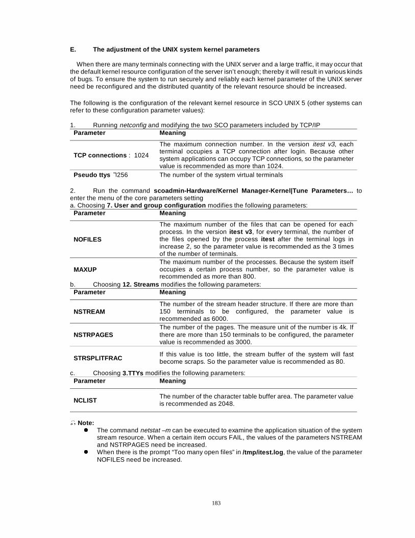
183
E. The adjustment of the UNIX system kernel parameters
When there are many terminals connecting with the UNIX server and a large traffic, it may occur that the default kernel resource configuration of the server isn’t enough; thereby it will result in various kinds of bugs. To ensure the system to run securely and reliably each kernel parameter of the UNIX server need be reconfigured and the distributed quantity of the relevant resource should be increased.
The following is the configuration of the relevant kernel resource in SCO UNIX 5 (other systems can refer to these configuration parameter values): 1. Running netconfig and modifying the two SCO parameters included by TCP/IP
Parameter Meaning
TCP connections : 1024
The maximum connection number. In the version itest v3, each terminal occupies a TCP connection after login. Because other system applications can occupy TCP connections, so the parameter value is recommended as more than 1024.
Pseudo ttys �256 The number of the system virtual terminals 2. Run the command scoadmin-Hardware/Kernel Manager-Kernel|Tune Parameters… to enter the menu of the core parameters setting a. Choosing 7. User and group configuration modifies the following parameters:
Parameter Meaning
NOFILES
The maximum number of the files that can be opened for each process. In the version itest v3 , for every terminal, the number of the files opened by the process itest after the terminal logs in increase 2, so the parameter value is recommended as the 3 times of the number of terminals.
MAXUP The maximum number of the processes. Because the system itself occupies a certain process number, so the parameter value is recommended as more than 800.
b. Choosing 12. Streams modifies the following parameters: Parameter Meaning
NSTREAM The number of the stream header structure. If there are more than 150 terminals to be configured, the parameter value is recommended as 6000.
NSTRPAGES The number of the pages. The measure unit of the number is 4k. If there are more than 150 terminals to be configured, the parameter value is recommended as 3000.
STRSPLITFRAC If this value is too little, the stream buffer of the system will fast become scraps. So the parameter value is recommended as 80.
c. Choosing 3.TTYs modifies the following parameters: Parameter Meaning
NCLIST The number of the character table buffer area. The parameter value is recommended as 2048.
� Note:
z The command netstat –m can be executed to examine the application situation of the system stream resource. When a certain item occurs FAIL, the values of the parameters NSTREAM and NSTRPAGES need be increased.
z When there is the prompt “Too many open files” in /tmp/itest.log , the value of the parameter NOFILES need be increased.

184
3.3 Monitoring, Debugging and Management of a Terminal This section includes the following aspects: a. The terminal information monitoring command b. The terminal information examining command c. The terminal management
A. The terminal information monitoring command
Router#debug terminal <terminal port numbe> Terminal number���-31>�
Command Description
socket < read rw write CR >
Examine the information read/written from the socket direction (the line) on the asynchronous port (you can choose: read information, read/write information�WKH GHIDXOW�� WKH ZULWH LQIRUPDWLRQ DQG XVe the default parameter).
terminal < read rw write CR >
Examine the information read/written from the socket direction (the line) on the asynchronous port (you can choose: read information, read/write information�WKH GHIDXOW�� WKH ZULWH LQIRUPDWLRQ DQG XVH the default parameter).
B. The terminal information examining command Router#show
Command Description
terminal <0-31> Examine the terminal speed, the receiving/sending buffer, the local address and the remote-end address, etc. (you can choose: the number 0-31 terminal).
uart < 0-1> <0-15> Examine the UART physical information corresponding with the terminal (you can choose: the number 0-15 terminal on the number 0-1 extended board).
ip sockets Examine the TCP connection status of the terminal. For example: 1. router#show terminal 0
Dax Terminal Server Version 1.26 line0: terminal - enable speed:9600 dataBits:8 stopBits:1 parity:none flowctl:none line-on:dsr rxBuf:128 txBuf:128 print:on, auto-linking:off, rx-delay:off host escape charaters: ^G ^D local host: 1.1.2.1 remote host: 0: HOST1 1.1.1.1 3051 fix-terminal client dis-connect statistics information:
tx bytes:0 rx bytes:0 Note:
The command examines the relevant parameters of the interface corresponding with the terminal, receiving/sending buffer size and the configuration of the remote host, etc.
2. router#show uart 0 0
UART 0/0: speed: 9600bps rx-FIFO-triger: 8 flow control: no flow control status: Allow-Self-Tx, Allow-Peer-Tx xoff_timeout: 180 (unit: 1/60 second)
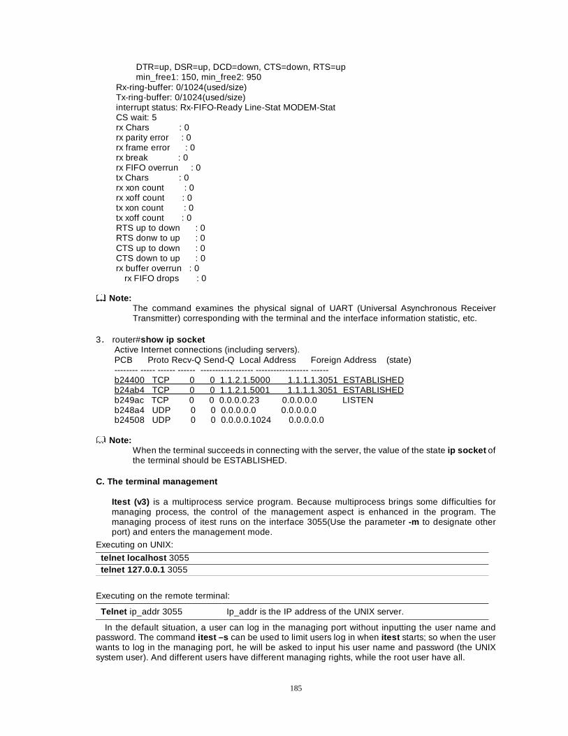
185
DTR=up, DSR=up, DCD=down, CTS=down, RTS=up min_free1: 150, min_free2: 950 Rx-ring-buffer: 0/1024(used/size) Tx-ring-buffer: 0/1024(used/size) interrupt status: Rx-FIFO-Ready Line-Stat MODEM-Stat CS wait: 5 rx Chars : 0 rx parity error : 0 rx frame error : 0 rx break : 0 rx FIFO overrun : 0 tx Chars : 0 rx xon count : 0 rx xoff count : 0 tx xon count : 0 tx xoff count : 0 RTS up to down : 0 RTS donw to up : 0 CTS up to down : 0 CTS down to up : 0 rx buffer overrun : 0
rx FIFO drops : 0 Note:
The command examines the physical signal of UART (Universal Asynchronous Receiver Transmitter) corresponding with the terminal and the interface information statistic, etc.
3Ê router#show ip socket Active Internet connections (including servers). PCB Proto Recv-Q Send-Q Local Address Foreign Address (state) -------- ----- ------ ------ ------------------ ------------------ ------ b24400 TCP 0 0 1.1.2.1.5000 1.1.1.1.3051 ESTABLISHED b24ab4 TCP 0 0 1.1.2.1.5001 1.1.1.1.3051 ESTABLISHED b249ac TCP 0 0 0.0.0.0.23 0.0.0.0.0 LISTEN b248a4 UDP 0 0 0.0.0.0.0 0.0.0.0.0 b24508 UDP 0 0 0.0.0.0.1024 0.0.0.0.0
Note:
When the terminal succeeds in connecting with the server, the value of the state ip socket of the terminal should be ESTABLISHED.
C. The terminal management
Itest (v3) is a multiprocess service program. Because multiprocess brings some difficulties for managing process, the control of the management aspect is enhanced in the program. The managing process of itest runs on the interface 3055(Use the parameter -m to designate other port) and enters the management mode.
Executing on UNIX:
telnet localhost 3055 telnet 127.0.0.1 3055
Executing on the remote terminal:
Telnet ip_addr 3055 Ip_addr is the IP address of the UNIX server.
In the default situation, a user can log in the managing port without inputting the user name and password. The command itest –s can be used to limit users log in when itest starts; so when the user wants to log in the managing port, he will be asked to input his user name and password (the UNIX system user). And different users have different managing rights, while the root user have all.
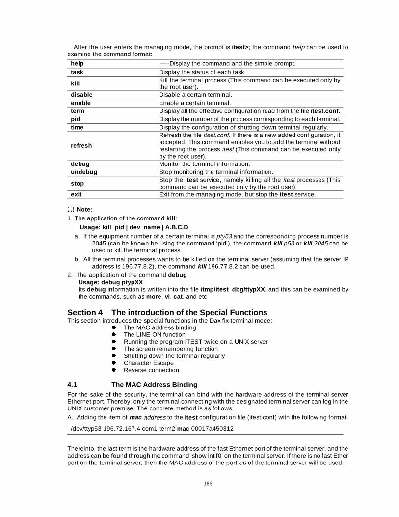
186
After the user enters the managing mode, the prompt is itest> ; the command help can be used to examine the command format:
help -----Display the command and the simple prompt. task Display the status of each task.
kill Kill the terminal process (This command can be executed only by the root user).
disable Disable a certain terminal. enable Enable a certain terminal. term Display all the effective configuration read from the file itest.conf. pid Display the number of the process corresponding to each terminal. time Display the configuration of shutting down terminal regularly.
refresh
Refresh the file itest.conf. If there is a new added configuration, it accepted. This command enables you to add the terminal without restarting the process itest (This command can be executed only by the root user).
debug Monitor the terminal information. undebug Stop monitoring the terminal information.
stop Stop the itest service, namely killing all the itest processes (This command can be executed only by the root user).
exit Exit from the managing mode, but stop the itest service. Note: 1. The application of the command kill :
Usage: kill pid | dev_name | A.B.C.D
a. If the equipment number of a certain terminal is pty53 and the corresponding process number is 2045 (can be known be using the command ‘pid’), the command kill p53 or kill 2045 can be used to kill the terminal process.
b. All the terminal processes wants to be killed on the terminal server (assuming that the server IP address is 196.77.8.2), the command kill 196.77.8.2 can be used.
2. The application of the command debug Usage: debug ptypXX Its debug information is written into the file /tmp/itest_dbg/ttypXX , and this can be examined by the commands, such as more , vi , cat , and etc.
Section 4 The introduction of the Special Functions This section introduces the special functions in the Dax fix-terminal mode:
z The MAC address binding z The LINE-ON function z Running the program ITEST twice on a UNIX server z The screen remembering function z Shutting down the terminal regularly z Character Escape z Reverse connection
4.1 The MAC Address Binding For the sake of the security, the terminal can bind with the hardware address of the terminal server Ethernet port. Thereby, only the terminal connecting with the designated terminal server can log in the UNIX customer premise. The concrete method is as follows:
A. Adding the item of mac address to the itest configuration file (itest.conf) with the following format:
/dev/ttyp53 196.72.167.4 com1 term2 mac 00017a450312
Thereinto, the last term is the hardware address of the fast Ethernet port of the terminal server, and the address can be found through the command ‘show int f0’ on the terminal server. If there is no fast Ether port on the terminal server, then the MAC address of the port e0 of the terminal server will be used.
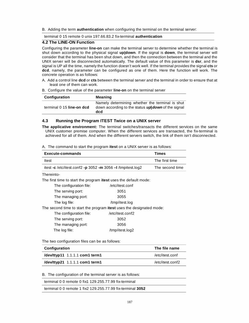
187
B. Adding the term authentication when configuring the terminal on the terminal server:
terminal 0 15 remote 0 unix 197.66.83.2 fix-terminal authentication
4.2 The LINE-ON Function Configuring the parameter line-on can make the terminal server to determine whether the terminal is shut down according to the physical signal up|down . If the signal is down , the terminal server will consider that the terminal has been shut down, and then the connection between the terminal and the UNIX server will be disconnected automatically. The default value of this parameter is dsr , and the signal is UP all the time, namely the function doesn’t work well. If the terminal provides the signal cts or dcd , namely, the parameter can be configured as one of them. Here the function will work. The concrete operation is as follows:
A. Add a control line dcd or cts between the terminal server and the terminal in order to ensure that at least one of them can work.
B. Configure the value of the parameter line-on on the terminal server
Configuration Meaning
terminal 0 15 line-on dcd Namely determining whether the terminal is shut down according to the status up|down of the signal dcd
4.3 Running the Program ITEST Twice on a UNIX server The applicative environment: The terminal switches/transacts the different services on the same
UNIX customer premise computer. When the different services are transacted, the fix-terminal is achieved for all of them. And when the different servers switch, the link of them isn’t disconnected.
A. The command to start the program itest on a UNIX server is as follows:
Execute-commands Times
Itest The first time
itest -c /etc/itest.conf2 -p 3052 -m 3056 –l /tmpitest.log2 The second time
Thereinto-
The first time to start the program itest uses the default mode: The configuration file: /etc/itest.conf
The serving port: 3051 The managing port: 3055
The log file: /tmp/itest.log The second time to start the program itest uses the designated mode:
The configuration file: /etc/itest.conf2
The serving port: 3052 The managing port: 3056
The log file: /tmp/itest.log2
The two configuration files can be as follows:
Configuration The file name
/dev/ttyp11 1.1.1.1 com1 term1 /etc/itest.conf
/dev/ttyp21 1.1.1.1 com1 term1 /etc/itest.conf2
B. The configuration of the terminal server is as follows:
terminal 0 0 remote 0 fix1 129.255.77.99 fix-terminal
terminal 0 0 remote 1 fix2 129.255.77.99 fix-terminal 3052
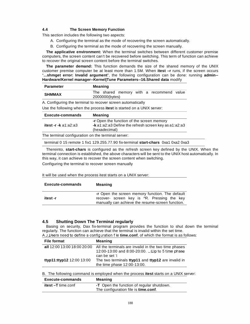
188
4.4 The Screen Memory Function This section includes the following two aspects:
A. Configuring the terminal as the mode of recovering the screen automatically.
B. Configuring the terminal as the mode of recovering the screen manually.
The applicative environment: When the terminal switches between different customer premise computers, the screen content can’t be recovered before switching. This term of function can achieve to recover the original screen content before the terminal switches.
The parameter demand: This function demands the size of the shared memory of the UNIX customer premise computer be at least more than 1.5M. When itest –r runs, if the screen occurs “...shmget error: Invalid argument ”, the following configuration can be done: running admin--Hardware/Kernel manager--Kernel|Tune Parameters--16.Shared data modify
Parameter Meaning
SHMMAX The shared memory with a recommend value 2000000(bytes)
A. Configuring the terminal to recover screen automatically
Use the following when the process itest is started on a UNIX server:
Execute-commands Meaning
itest -r -k a1:a2:a3 -r Open the function of the screen memory -k a1:a2:a3 Define the refresh screen key as a1:a2:a3 (hexadecimal)
The terminal configuration on the terminal server:
terminal 0 15 remote 1 fix1 129.255.77.90 fix-terminal start-chars 0xa1 0xa2 0xa3
Thereinto, start-chars is configured as the refresh screen key defined by the UNIX. When the terminal connection is established, the above characters will be sent to the UNIX host automatically. In this way, it can achieve to recover the screen content when switching.
Configuring the terminal to recover screen manually
It will be used when the process itest starts on a UNIX server:
Execute-commands Meaning
itest -r -r Open the screen memory function. The default recover- screen key is ^R. Pressing the key manually can achieve the resume-screen function.
4.5 Shutting Down The Terminal regularly Basing on security, Dax fix-terminal program provides the function to shut down the terminal
regularly. The function can achieve that the terminal is invalid within the set time. A��8VHUV QHHG WR GHILQH D FRQILJXUDWLRQ ILOH time.conf , of which the format is as follows:
File format Meaning
all 12:00 13:00 18:00 20:00 All the terminals are invalid in the two time phases 12:00-13:00 and 8:00-20:00. ��8S WR � WLPH SKDVH
can be set� ttyp11:ttyp12 12:00 13:00 The two terminals ttyp11 and ttyp12 are invalid in
the time phase 12:00-13:00. B. The following command is employed when the process itest starts on a UNIX server:
Execute-commands Meaning
itest –T time.conf -T Open the function of regular shutdown. The configuration file is time.conf .
189
4.6 Character Escape For the request of some application programs, the characters sent by the terminal can be
transformed into other characters according to the configuration. A. Users need to define a configuration file keymap.conf. The format of the file is as follows:
The file format Meaning
4f:50 1b:4f:50 Transform the character 4f:50 into 1b:4f:50.
4f:51 1b:4f:51 Transform the character 4f:51 into 1b:4f:51.
B. When the process itest runs on a UNIX server, the following command is used:
Execute-commands Meaning
itest –M keymap.conf -M Open the character escape function. The configuration file is keymap.conf.
4.7 Reverse Connection
In the default login mode of fix-terminal, UNIX, regarded as the server, opens the server interface 3051; and the terminal server, regarded as the client, originates the request to establish the link; and the interface number can be random. In order that the hidden trouble of opening the interface 3051 can be eliminated, UNIX can be regarded as the client and the terminal server as the server, and the TCP connection will be established. In this way, the number of the interface opened in UNIX is random, and the number of the interface opened in the terminal server is 3051. The detailed method is as follows: A. When the process itest start on a UNIX server, the following command is employed:
Execute-commands Meaning
itest –a UNIX is designated as the client and originates the request to establish the TCP link
A. B. When the terminal is configured, it is designated as the server working mode:
terminal 0 15 remote 1 fix1 129.255.77.90 fix-terminal server
190
Chapter 12 Security Configuration
Dax-Maipu has a comprehensive network security scheme on the reliability, circuitry security, access control and information concealment, data encryption and security management .It mainly includes:
1. PPP protocol supports PAP and CHAP, which effectively prevents the unauthorized connection; 2. Callback technology; 3. IP protocol layer provides the firewall function, which can filter data packet and prevent
unauthorized data packet from coming in/out of the router. 4. NAT can hide interior network and avoid attacks from exterior network. 5. ACL, in terms of actual need, can sort the terminal users into up to 15 classes, can register
different classes of commands for the corresponding users, and insure users with different rights can only use the corresponding commands.
6. Encryption and key exchange technologies
This chapter mainly describes how to make security configuration of DXMP ROUTER Router. The contents of the chapter are: � )LUHZDOO FRQILJXUDWLRQ � 1$7 �1HWZRUN $GGUHVV 7UDQVODWLRQ� FRQILJXUDWLRQ � (DV\ ,3 FRQILJXUDWLRQ � ,36HF QHWZRUN VHcurity configuration � &RQILJXUDWLRQ RI $&/�$FFHVV &RQWURO /LVWV� XVHUV JURXS FRQWURO � Usage of encryption module � ,.( FRQILJXUDWLRQ
Section one Configuring Firewall
� ,QWURGXFWLRQ RI ILUHZDOO � $FFHVV OLVW � Correlative configuration of firewall � $SSOication of access lists to an interface � 0RQLWRU DQG PDLQWHQDQFH RI D ILUHZDOO � $FFHVV FKDQQHO � 1RWLFHDEOH SRLQWV RQ ILUHZDOO FRQILJXUDWLRQ
1.1 Introduction Firewall A firewall is a system that is used to perform security defense mechanism between the interior network and the exterior network. And it is an access control mechanism used to control what interior/exterior services can be accessed.
The firewall is an effective network security mechanism. Its functions are as follows: � WR UHVWULFW DFFHVVLQJ the points controlled strictly; � WR SUHYHQW DWWDFNHUV IURP IXUWKHU DSSURDFKLQJ RWKHU GHIHQVLYH HTXLSPHQWV�
The basic guidelines of the firewall are as follows:
1) All unallowable actions are denied. Based on the guideline, it is a very applied method for the firewall to close off all information streams, and then open the corresponding services that are expected to be provided one by one.
2) All not denied are allowable. Based on the guideline, the firewall should transmit all information streams, and then screen off all deleterious services. This method constructs a more flexible application environment and can provide users with more services. The disadvantage of this method is that the increasing network services add great amount of maintenance to network managers. Especially when the scope of the protected network is extended, it is very difficult for network managers to provide users with reliable security protection. The basic types of firewall are as follows:
1) Packet filtering firewall: the packet filtering is installed in a router. Packet filtering rules are based on the information of IP packet, and filter IP source address, IP destination address, protocol type and the fields of protocols (such as port number of TCP and UDP, type and code of ICMP, type of IGMP).
2) Proxy service firewall 3) Hybrid firewall 4) Others
191
Dax-Maipu series adopt the packet filtering firewall. The firewall configuration task list includes:
1) Creating a standard access list, 2) Creating an extended access list, 3) Deleting an access list, 4) Configuring the relative items of the firewall, 5) Applying an access list to an interface.
When configuration is finished, the packet filtering firewall works as the following mode:
1) The packet header is analyzed by every rule in the list bound to the interface when the packet arrives at the interface (The fields of packet header of IP, TCP, UDP, ICMP, and IGMP can be examined);
2) The definition order of each rule is consistent with application order of each rule; 3) The packet is not permitted if one rule denies the packet passing/being received. 4) The packet is processed successively when it is permitted by one rule. And if the packet doesn’t
meet any rule, it is processed by the default rule(s). 1.2 An Access List
The following contents of an access list will be introduced: � %DVLF LQWURGXFWLRQ RI DQ DFFHVV OLVW� � (GLW D VWDQGDUG DFFHVV OLVW� � (GLW DQ H[WHQGHG DFFHVV OLVW�
A. Introduction of an Access List Even as an access list’s name means, its original idea is to permit or to deny packet coming in, flowing out or passing through a router. The access list is a strong tool, and its basic functions can be sorted into three classes: security filtering, traffic control, and packet identity. The access list filtering is a processing procedure from the top down. A packet can be executed if it is permitted or denied, or else it will be matched by the next rule of the stack. the matching principles are applied to each filtering rule. If a matching happens and the specified action rules match unsuccessfully, the default rule goes on. The logical-stream figure of packet matching a rule of the access list is shown as follows: Note :
The default rule is: all packets that cannot be matched successfully will be denied.
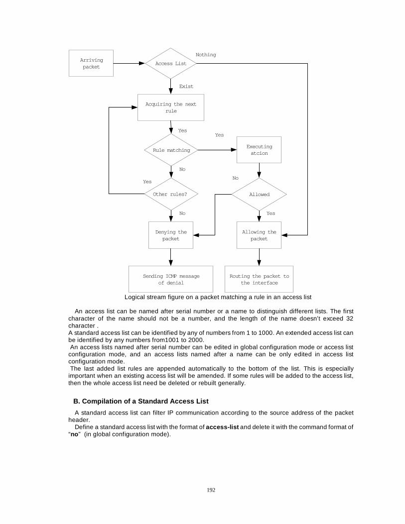
192
Arrivingpacket
Access List
Acquiring the nextrule
Rule matching
Other rules?
Denying thepacket
Sending ICMP messageof denial
Executingatcion
Allowed
Allowing thepacket
Routing the packet tothe interface
Nothing
Exist
Yes
No
Yes
No
Yes
No
Yes
Logical stream figure on a packet matching a rule in an access list
An access list can be named after serial number or a name to distinguish different lists. The first
character of the name should not be a number, and the length of the name doesn’t exceed 32 character . A standard access list can be identified by any of numbers from 1 to 1000. An extended access list can be identified by any numbers from1001 to 2000. An access lists named after serial number can be edited in global configuration mode or access list configuration mode, and an access lists named after a name can be only edited in access list configuration mode. The last added list rules are appended automatically to the bottom of the list. This is especially important when an existing access list will be amended. If some rules will be added to the access list, then the whole access list need be deleted or rebuilt generally.
B. Compilation of a Standard Access List
A standard access list can filter IP communication according to the source address of the packet header.
Define a standard access list with the format of access-list and delete it with the command format of “no ” (in global configuration mode).
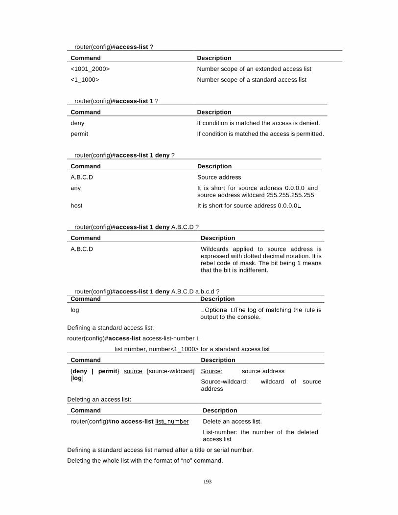
193
router(config)#access-list ?
Command Description
<1001_2000> Number scope of an extended access list
<1_1000> Number scope of a standard access list
router(config)#access-list 1 ?
Command Description
deny If condition is matched the access is denied.
permit If condition is matched the access is permitted.
router(config)#access-list 1 deny ?
Command Description
A.B.C.D Source address
any It is short for source address 0.0.0.0 and source address wildcard 255.255.255.255
host It is short for source address 0.0.0.0�
router(config)#access-list 1 deny A.B.C.D ?
Command Description
A.B.C.D Wildcards applied to source address is expressed with dotted decimal notation. It is rebel code of mask. The bit being 1 means that the bit is indifferent.
router(config)#access-list 1 deny A.B.C.D a.b.c.d ? Command Description
log �2SWLRQDO �7KH ORJ RI PDWFKLQJ WKH UXOH LV
output to the console.
Defining a standard access list:
router(config)#access-list access-list-number �
list number, number<1_1000> for a standard access list
Command Description
{deny | permit } source [source-wildcard] [log ]
Source: source address
Source-wildcard: wildcard of source address
Deleting an access list:
Command Description
router(config)#no access-list list�QXPEHU
Delete an access list.
List-number: the number of the deleted access list
Defining a standard access list named after a title or serial number.
Deleting the whole list with the format of “no” command.
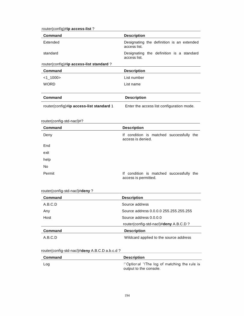
194
router(config)#ip access-list ?
Command Description
Extended Designating the definition is an extended access list.
standard Designating the definition is a standard access list.
router(config)#ip access-list standard ?
Command Description
<1_1000> List number
WORD List name
Command Description
router(config)#ip access-list standard 1 Enter the access list configuration mode.
router(config-std-nacl)#?
Command Description
Deny If condition is matched successfully the access is denied.
End
exit
help
No
Permit If condition is matched successfully the access is permitted.
router(config-std-nacl)#deny ?
Command Description
A.B.C.D Source address
Any Source address 0.0.0.0 255.255.255.255
Host Source address 0.0.0.0
router(config-std-nacl)#deny A.B.C.D ?
Command Description
A.B.C.D Wildcard applied to the source address
router(config-std-nacl)#deny A.B.C.D a.b.c.d ?
Command Description
Log �2SWLRQDO �7KH ORJ RI PDWFKLQJ WKH UXOH LV
output to the console.
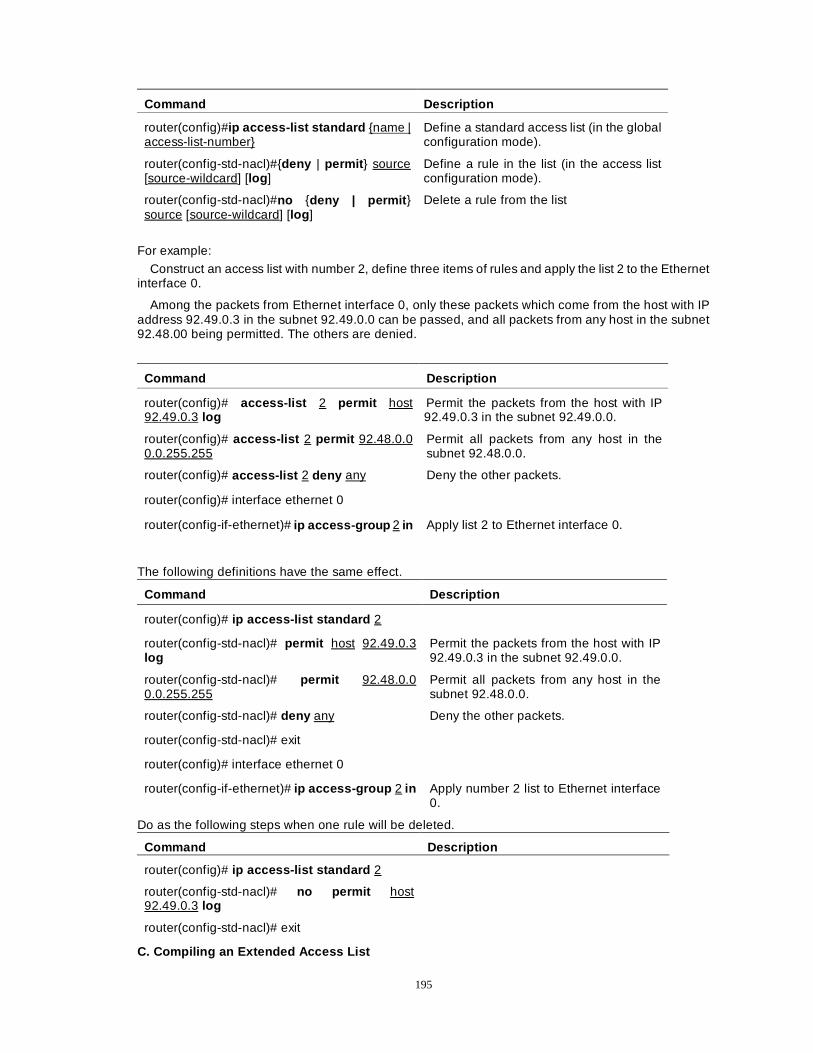
195
Command Description
router(config)#ip access-list standard {name | access-list-number}
Define a standard access list (in the global configuration mode).
router(config-std-nacl)#{deny | permit } source [source-wildcard] [log ]
Define a rule in the list (in the access list configuration mode).
router(config-std-nacl)#no {deny | permit } source [source-wildcard] [log ]
Delete a rule from the list
For example:
Construct an access list with number 2, define three items of rules and apply the list 2 to the Ethernet interface 0.
Among the packets from Ethernet interface 0, only these packets which come from the host with IP address 92.49.0.3 in the subnet 92.49.0.0 can be passed, and all packets from any host in the subnet 92.48.00 being permitted. The others are denied.
Command Description
router(config)# access-list 2 permit host 92.49.0.3 log
Permit the packets from the host with IP 92.49.0.3 in the subnet 92.49.0.0.
router(config)# access-list 2 permit 92.48.0.0 0.0.255.255
Permit all packets from any host in the subnet 92.48.0.0.
router(config)# access-list 2 deny any Deny the other packets.
router(config)# interface ethernet 0
router(config-if-ethernet)# ip access-group 2 in Apply list 2 to Ethernet interface 0.
The following definitions have the same effect.
Command Description
router(config)# ip access-list standard 2
router(config-std-nacl)# permit host 92.49.0.3 log
Permit the packets from the host with IP 92.49.0.3 in the subnet 92.49.0.0.
router(config-std-nacl)# permit 92.48.0.0 0.0.255.255
Permit all packets from any host in the subnet 92.48.0.0.
router(config-std-nacl)# deny any Deny the other packets.
router(config-std-nacl)# exit
router(config)# interface ethernet 0
router(config-if-ethernet)# ip access-group 2 in Apply number 2 list to Ethernet interface 0.
Do as the following steps when one rule will be deleted.
Command Description
router(config)# ip access-list standard 2
router(config-std-nacl)# no permit host 92.49.0.3 log
router(config-std-nacl)# exit
C. Compiling an Extended Access List

196
An extended access list can used to filter IP communication not only according to the source address and the destination address of the IP packet header, but also according to the fields included into the packet header of IP, UDP, TCP, ICMP and IGMP.
router71(config)#access-list 1001 ? 1001-2000 indicates it is an extended access list
Command Description
deny If condition is matched the access is denied.
permit If condition is matched the access is permitted.
router(config)#access-list 1001 deny ?
Command Description
<0_255> Number of ALL kinds of protocols
icmp Internet Control Message Protocol (ICMP)
igmp Internet Group Management Protocol (IGMP)
ip All Internet Protocols
tcp Transmission Control Protocol (TCP)
udp User Data Protocol(UDP)
Define an extended access list named after a number with the extended format of access-list and delete the list with the command of no (in the global configuration mode).
access-list access-list-number {deny | permit } protocol source source-wildcard [operator port [port]] ] destination destination-wildcard [icmp-type] [igmp-type] [operator port [port]] [ack / fin / established / psh / rst / syn / urg] [precedence precedence] [tos tos] [log ]
Parameter Description
access-list-number List number
Protocol Protocol
Source Packet source address
source-wildcard Wildcard of source address
Destination Packet destination address
destination-wildcard Wildcard of destination address
Precedence Priority
tos Service type
log Log
icmp-type Message type of ICMP
igmp-type Message type of IGMP
Operator Port comparison
port Port
port Port number
ack / fin / established / psh / rst / syn / urg TCP flag bit
Define an extended access list named after a name or a number according to the following steps and delete the whole list with the command format of no (in the global configuration mode).
ip access-list extended {access-list-number/name}
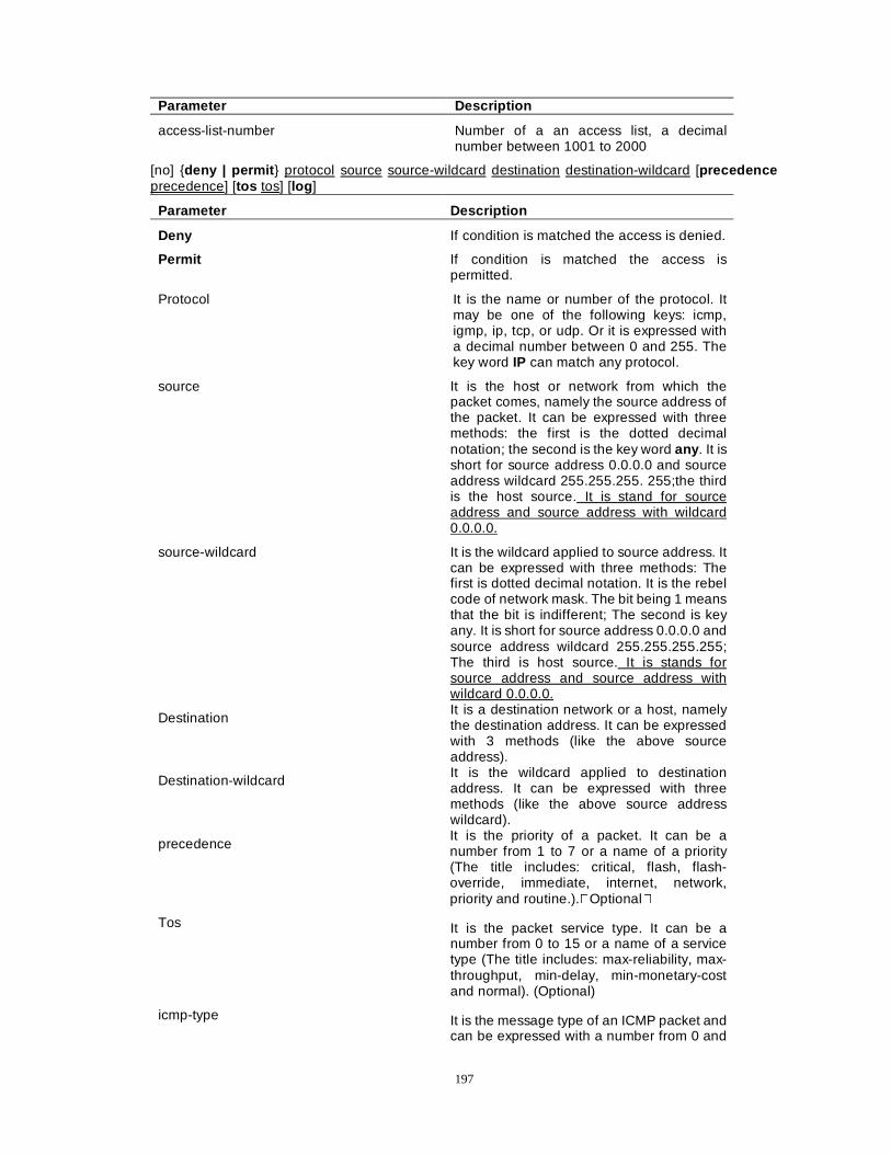
197
Parameter Description
access-list-number Number of a an access list, a decimal number between 1001 to 2000
[no] {deny | permit } protocol source source-wildcard destination destination-wildcard [precedence precedence] [tos tos] [log ]
Parameter Description
Deny If condition is matched the access is denied.
Permit If condition is matched the access is permitted.
Protocol It is the name or number of the protocol. It may be one of the following keys: icmp, igmp, ip, tcp, or udp. Or it is expressed with a decimal number between 0 and 255. The key word IP can match any protocol.
source It is the host or network from which the packet comes, namely the source address of the packet. It can be expressed with three methods: the first is the dotted decimal notation; the second is the key word any . It is short for source address 0.0.0.0 and source address wildcard 255.255.255. 255;the third is the host source. It is stand for source address and source address with wildcard 0.0.0.0.
source-wildcard It is the wildcard applied to source address. It can be expressed with three methods: The first is dotted decimal notation. It is the rebel code of network mask. The bit being 1 means that the bit is indifferent; The second is key any. It is short for source address 0.0.0.0 and source address wildcard 255.255.255.255; The third is host source. It is stands for source address and source address with wildcard 0.0.0.0.
Destination It is a destination network or a host, namely the destination address. It can be expressed with 3 methods (like the above source address).
Destination-wildcard It is the wildcard applied to destination address. It can be expressed with three methods (like the above source address wildcard).
precedence It is the priority of a packet. It can be a number from 1 to 7 or a name of a priority (The title includes: critical, flash, flash-override, immediate, internet, network, priority and routine.).�Optional�
Tos It is the packet service type. It can be a number from 0 to 15 or a name of a service type (The title includes: max-reliability, max-throughput, min-delay, min-monetary-cost and normal). (Optional)
icmp-type It is the message type of an ICMP packet and can be expressed with a number from 0 and
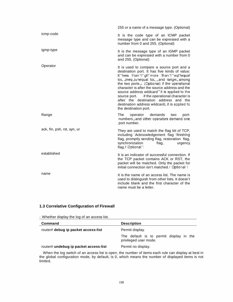
198
255 or a name of a message type. (Optional)
icmp-code It is the code type of an ICMP packet message type and can be expressed with a number from 0 and 255. (Optional)
igmp-type It is the message type of an IGMP packet and can be expressed with a number from 0 and 255. (Optional)
Operator It is used to compare a source port and a destination port. It has five kinds of value: lt�OHVV WKDQ��JW�PRUH WKDQ��HT�HTXDO
to��QHT�XQHTXDO WR��DQG UDQJH�DPRQJ
the two ports�� �2SWLRQDO� ,I WKH RSHUDWLRQDO
character is after the source address and the source address wildcard�LW LV DSSOLHG WR WKH
source port. if the operational character is after the destination address and the destination address wildcard�LW LV DSSOLHG WR
the destination port.
Range The operator demands two port-numbers�DQG RWKHU RSHUDWRUV GHPDQG RQH
port number.
ack, fin, psh, rst, syn, ur They are used to match the flag bit of TCP, including�Acknowledgement flag�ILQLVKLQJ
flag, promptly sending flag, restoration flag, synchronization flag, urgency flag.�2SWLRQDO�
established It is an indicator of successful connection. If the TCP packet contains ACK or RST, the packet will be matched. Only the packet for initial connection isn’t matched.�2SWLRQDO�
name It is the name of an access list. The name is used to distinguish from other lists. It doesn’t include blank and the first character of the name must be a letter.
1.3 Correlative Configuration of Firewall
· Whether display the log of an access list.
Command Description
router# debug ip packet access-list Permit display.
The default is to permit display in the privileged user mode.
router# undebug ip packet access-list Permit no display.
When the log switch of an access list is open, the number of items each rule can display at best in the global configuration mode, by default, is 0, which means the number of displayed items is not limited.
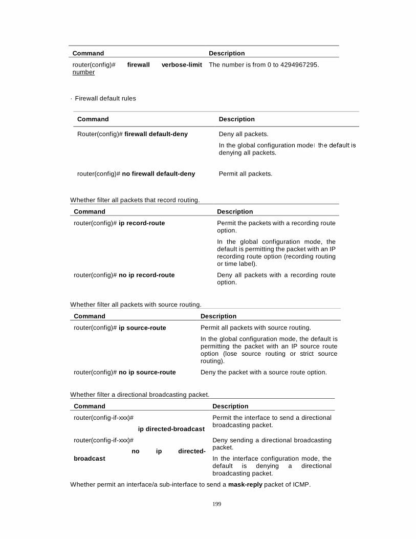
199
Command Description
router(config)# firewall verbose-limit number
The number is from 0 to 4294967295.
· Firewall default rules
Whether filter all packets that record routing.
Command Description
router(config)# ip record-route Permit the packets with a recording route option.
In the global configuration mode, the default is permitting the packet with an IP recording route option (recording routing or time label).
router(config)# no ip record-route Deny all packets with a recording route option.
Whether filter all packets with source routing.
Command Description
router(config)# ip source-route Permit all packets with source routing.
In the global configuration mode, the default is permitting the packet with an IP source route option (lose source routing or strict source routing).
router(config)# no ip source-route Deny the packet with a source route option.
Whether filter a directional broadcasting packet.
Command Description
router(config-if-xxx)#
ip directed-broadcast
Permit the interface to send a directional broadcasting packet.
router(config-if-xxx)#
no ip directed-broadcast
Deny sending a directional broadcasting packet.
In the interface configuration mode, the default is denying a directional broadcasting packet.
Whether permit an interface/a sub-interface to send a mask-reply packet of ICMP.
Command Description
Router(config)# firewall default-deny Deny all packets.
In the global configuration mode�WKH GHIDXOW LV
denying all packets.
router(config)# no firewall default-deny Permit all packets.
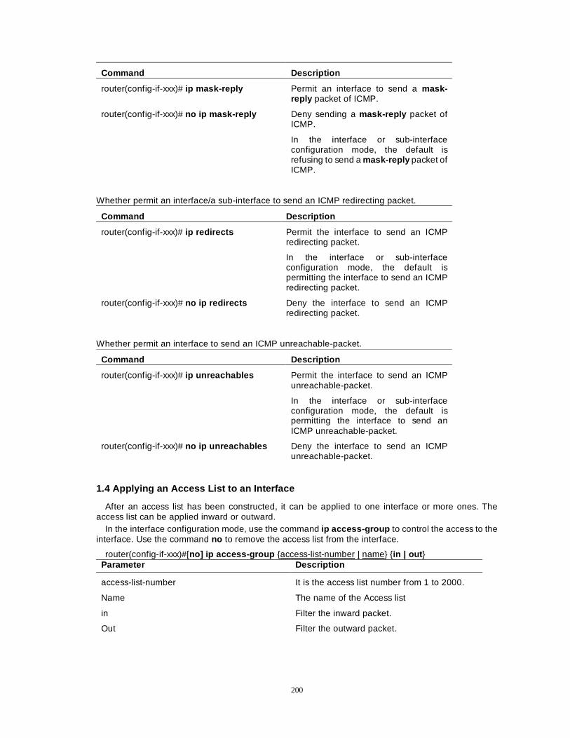
200
Command Description
router(config-if-xxx)# ip mask-reply Permit an interface to send a mask-reply packet of ICMP.
router(config-if-xxx)# no ip mask-reply Deny sending a mask-reply packet of ICMP.
In the interface or sub-interface configuration mode, the default is refusing to send a mask-reply packet of ICMP.
Whether permit an interface/a sub-interface to send an ICMP redirecting packet.
Command Description
router(config-if-xxx)# ip redirects Permit the interface to send an ICMP redirecting packet.
In the interface or sub-interface configuration mode, the default is permitting the interface to send an ICMP redirecting packet.
router(config-if-xxx)# no ip redirects Deny the interface to send an ICMP redirecting packet.
Whether permit an interface to send an ICMP unreachable-packet.
Command Description
router(config-if-xxx)# ip unreachables Permit the interface to send an ICMP unreachable-packet.
In the interface or sub-interface configuration mode, the default is permitting the interface to send an ICMP unreachable-packet.
router(config-if-xxx)# no ip unreachables Deny the interface to send an ICMP unreachable-packet.
1.4 Applying an Access List to an Interface
After an access list has been constructed, it can be applied to one interface or more ones. The access list can be applied inward or outward.
In the interface configuration mode, use the command ip access-group to control the access to the interface. Use the command no to remove the access list from the interface.
router(config-if-xxx)#[no] ip access-group {access-list-number | name} {in | out } Parameter Description
access-list-number It is the access list number from 1 to 2000.
Name The name of the Access list
in Filter the inward packet.
Out Filter the outward packet.
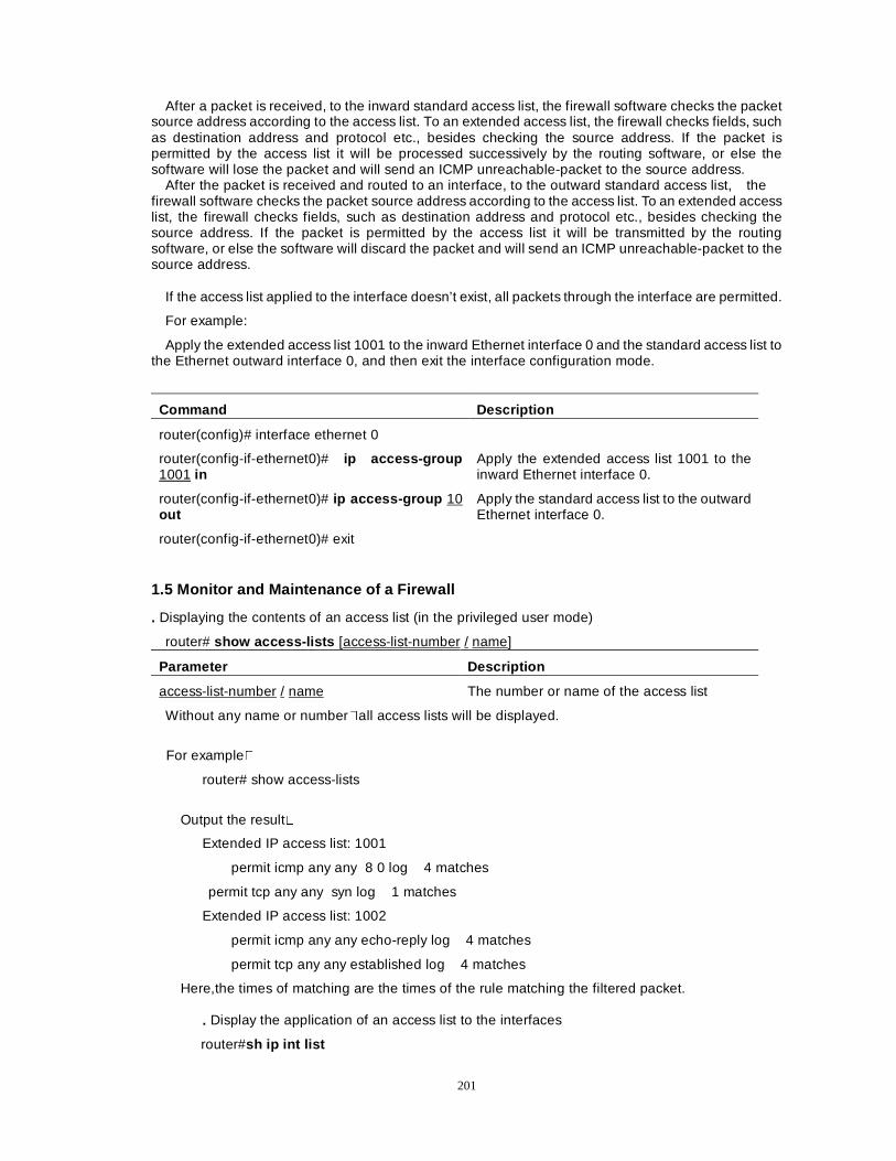
201
After a packet is received, to the inward standard access list, the firewall software checks the packet source address according to the access list. To an extended access list, the firewall checks fields, such as destination address and protocol etc., besides checking the source address. If the packet is permitted by the access list it will be processed successively by the routing software, or else the software will lose the packet and will send an ICMP unreachable-packet to the source address.
After the packet is received and routed to an interface, to the outward standard access list, the firewall software checks the packet source address according to the access list. To an extended access list, the firewall checks fields, such as destination address and protocol etc., besides checking the source address. If the packet is permitted by the access list it will be transmitted by the routing software, or else the software will discard the packet and will send an ICMP unreachable-packet to the source address.
If the access list applied to the interface doesn’t exist, all packets through the interface are permitted.
For example:
Apply the extended access list 1001 to the inward Ethernet interface 0 and the standard access list to the Ethernet outward interface 0, and then exit the interface configuration mode.
Command Description
router(config)# interface ethernet 0
router(config-if-ethernet0)# ip access-group 1001 in
Apply the extended access list 1001 to the inward Ethernet interface 0.
router(config-if-ethernet0)# ip access-group 10 out
Apply the standard access list to the outward Ethernet interface 0.
router(config-if-ethernet0)# exit
1.5 Monitor and Maintenance of a Firewall
. Displaying the contents of an access list (in the privileged user mode)
router# show access-lists [access-list-number / name]
Parameter Description
access-list-number / name The number or name of the access list
Without any name or number�all access lists will be displayed.
For example�
router# show access-lists
Output the result�
Extended IP access list: 1001
permit icmp any any 8 0 log 4 matches
permit tcp any any syn log 1 matches
Extended IP access list: 1002
permit icmp any any echo-reply log 4 matches
permit tcp any any established log 4 matches
Here,the times of matching are the times of the rule matching the filtered packet. . Display the application of an access list to the interfaces
router#sh ip int list
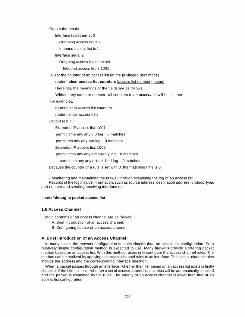
202
Output the result�
Interface fastethernet 0
Outgoing access list is 2
Inbound access list is 1
Interface serial 2
Outgoing access list is not set
Inbound access list is 1001
. Clear the counter of an access list (in the privileged user mode)
router# clear access-list counters [access-list-number | name]
Thereinto, the meanings of the fields are as follows�
Without any name or number�DOO FRXQWHUV RI DQ DFFHVV OLVW ZLOO EH FOHDUHG�
For example�
router# clear access-list counters
router# show access-lists
Output result�
Extended IP access list: 1001
permit icmp any any 8 0 log 0 matches
permit tcp any any syn log 0 matches
Extended IP access list: 1002
permit icmp any any echo-reply log 0 matches
permit tcp any any established log 0 matches
Because the counter of a rule is set with 0, the matching time is 0.
· Monitoring and maintaining the firewall through examining the log of an access list Records of the log include information, such as source address, destination address, protocol type,
port number and sending/receiving interface etc.
router#debug ip packet access-list
1.6 Access Channel
Main contents of an access channel are as follows� A. Brief introduction of an access channel, B. Configuring course of an access channel.
A. Brief Introduction of an Access Channel: In many cases, the network configuration is much simpler than an access list configuration. So a
relatively simple configuration method is expected to use. Many firewalls provide a filtering packet method based on an access list. With this method, users only configure the access channel rules. The method can be realized by applying the access channel rules to an interface. The access channel rules include the address and the corresponding interface direction.
When a packet passes through an interface, whether the filter based on an access list exists is firstly checked. If the filter isn’t set, whether a set of access channel rules exists will be automatically checked and the packet is examined by the rules. The priority of an access channel is lower than that of an access list configuration.
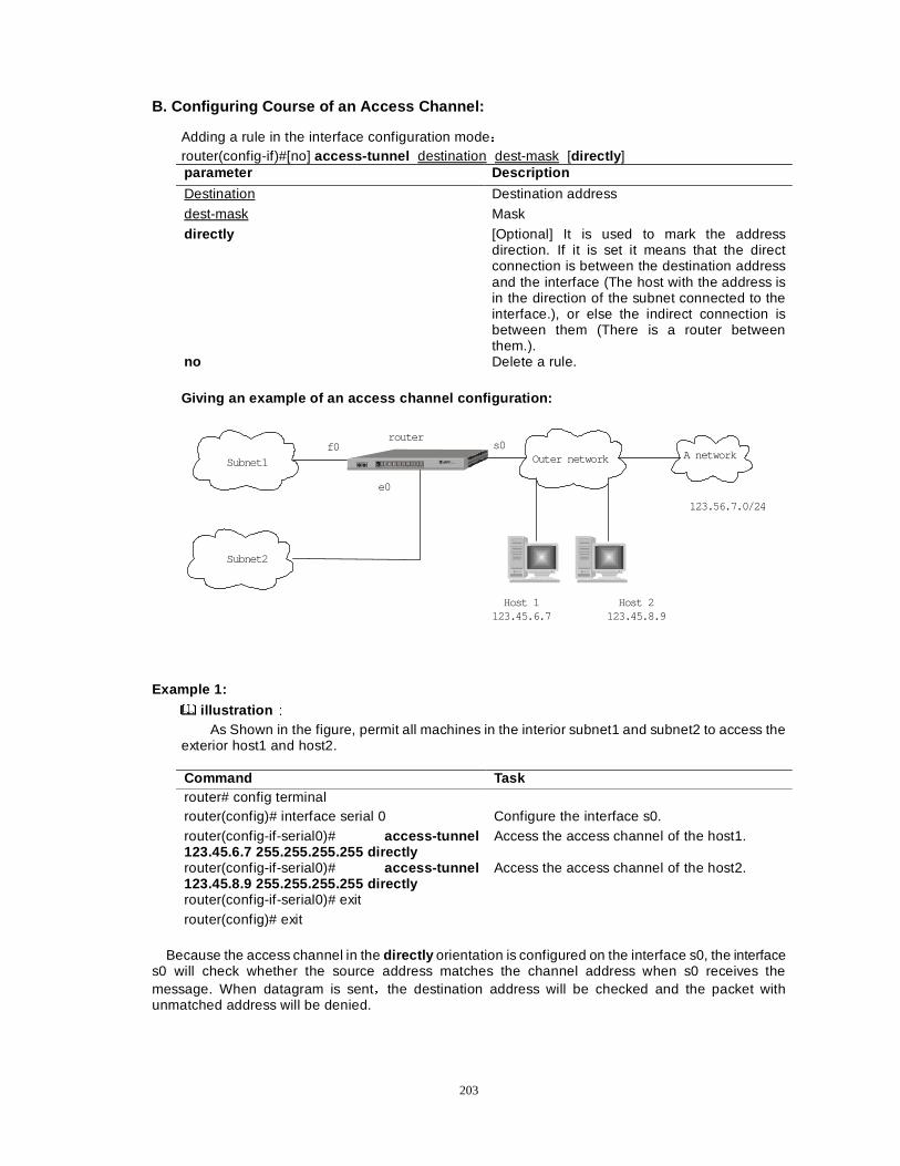
203
B. Configuring Course of an Access Channel:
Adding a rule in the interface configuration modeÖ router(config-if)#[no] access-tunnel destination dest-mask [directly ] parameter Description
Destination Destination address
dest-mask Mask
directly [Optional] It is used to mark the address direction. If it is set it means that the direct connection is between the destination address and the interface (The host with the address is in the direction of the subnet connected to the interface.), or else the indirect connection is between them (There is a router between them.).
no Delete a rule.
Giving an example of an access channel configuration:
Host 1123.45.6.7
Host 2123.45.8.9
123.56.7.0/24
f0
e0
s0router
Outer network A networkSubnet1
Subnet2
Example 1:
illustration ÛÛ As Shown in the figure, permit all machines in the interior subnet1 and subnet2 to access the
exterior host1 and host2.
Command Task router# config terminal router(config)# interface serial 0 Configure the interface s0. router(config-if-serial0)# access-tunnel 123.45.6.7 255.255.255.255 directly
Access the access channel of the host1.
router(config-if-serial0)# access-tunnel 123.45.8.9 255.255.255.255 directly
Access the access channel of the host2.
router(config-if-serial0)# exit router(config)# exit
Because the access channel in the directly orientation is configured on the interface s0, the interface
s0 will check whether the source address matches the channel address when s0 receives the message. When datagram is sentÈthe destination address will be checked and the packet with unmatched address will be denied.
204
Example 2:
illustration ÛÛ In the above figure, the subnet1 is permitted to access host 1, host 2 and the exterior subnet
123.56.7.0/24; the subnet 2 is not restricted: The access channel can’t be set on the exterior interface s0 and it should be set on the interface f0
connected to the subnet1.
Command Task router# config terminal router(config)# interface f0 Configure the interface f0. router(config-if-fastethernet0)# acce 123.45.6.7 255.255.255.255
Access the access channel of the host1.
router(config-if-fastethernet0)# acce 123.45.8.9 255.255.255.255
Accessing the access channel of the host2.
router(config-if-fastethernet0)# acce 123.56.7.0 255.255.255.0
Access the access channel of the network 123.56.7.0.
router(config-if-fastethernet0)# exit router(config)# exit
NoteÛÛ
1) Many channel rules on an interface are configured in a directionÜ 2) Try to avoid many interfaces being simultaneously configured with channel rules. If a datagram passes through two interfaces both configured with channel rules, it can’t be permitted until it passes both examinations. 3) Please do not configure a firewall and an access channel on the router simultaneously. Or else it will result in some baffling phenomena because of the priority. 4) An access channel only adapts to some quite simple situations. To some complex
situationsÍplease configure a firewall based on access list.
1.7 Packet Filtering Based on Time Limit
Users often have some similar demands Only in the working time of every workday except all festivals, can all machines in a network fragment can access a server On a Saturday afternoon, all machines are permitted to connect to Internet. All the similar demands based on time can be met through defining a time range and realizing the security mechanism of binding a time range to packet filtering. 1.Time Range
A time range is a set of time segments. A time range can include many time segments. The time scope of a time range is a disjunction of every time segment.
Definition: defining a time range in the configuration mode or the interface mode Command Description
Dax26(config)# time-range time_range_name This command enters the time range configuration mode. If the time range with the same name doesn’t exist, a new one will be created.
Dax26(config)# no time-range time_range_name Delete a time range with the command “no ”
There are two kinds of time segments: a relative time segment and an absolute time segment. The
former refers to a week; the latter refers to a certain date (x moth x day, x year).
205
A relative time segment: Defining a relative time segment in the time segment configuration mode Command Description periodic [days-of-the-week] [hh:mm] to [days-of-the-week] [hh:mm]
Check whether an equivalent structure has existed before a segment is added. If the segment doesn’t exist, it will be created. Delete a segment with the command “no ”. The default of date is daily and the default of time is 0Ö00 and 24Ö00 respectively.
An example:
Command Task periodic 8:00 to 17:30êperiodic daily 8:00 to 17:30
From 8Ö00 to 17:30
periodic weekday Saturday 8:00 to 17:00 Workdays (from Monday to Friday) and from 8:00 to 17:00 on Saturday
periodic Friday 17:30 to Monday 8:00 From 17:30 on Friday to 8:00ap on the next Monday
Absolute time segment: The command format is as follows and Delete a segment with command “no ”:
Command Description absolute [start time date ] [end time date] Any of the start clause and end clause can be
omitted. Omitting any clause means “do not stop until…” or “start when…”.
An exampleÖ Command Task absolute start 8:00 31 january 1999 end 8:00 15 february 2001
absolute start 0:00 1 october end 24:00 3 The holiday of National Day in every year 2. An application of a time range
Display the status of a time range: No matter which level (filtering rule or access list) a time range is bound to, whether the time range
works depends on the current status. There are two kinds of statusÖ ON and OFF. And the status of the time range depends on the respective current statuses of all time segments of which the time range is composed.
Refreshing status: The default refreshing cycle of a time range is one minute. Because the automatic refreshing depends on the current time of the system, the refreshing status, compared with the system time, may be delayed 0-60 seconds. 3.Compared with Cisco configuration
Cisco permits a piece of absolute segment rule in a time range and Dax can permit many pieces The absolute time in Cisco is a kind of a genuinely absolute time and the date must be in a rigorous format: day, month and year. But the time in Dax is a kind of relatively absolute time, and month and year can be omitted. 4.Dealing with the time judgment:
Binding a time range to a packet filtering Binding a time range to a packet filtering means that the packet filtering can work only when the
status of the time range is on . The command format is consistent with Cisco ’sÈfor exampleÖ
Command Description permit any log time-range t_r_name1 access-list 1001 deny tcp any any time-range t_r_name2
206
Namely add “time range name of time-range ” to the bottom of filtering rules. Its syntax position is after the position of log, which is same with Cisco’s. There is no special command to cancel the binding relationship. The method to cancel the binding is firstly deleting the filtering rule and then re-adding a same filtering rule without time limit.
Explain: When filtering rules are compared (The action can be performed in adding/deleting a rules.) the term trange does not participate in matching-namely two filtering rules(one of them is bound to a time range) are treated as a same rule because there is no need for distinguishing them. Just think if there are two such filtering rules in a access list, then the rule with the time limit does not work. Dealing with filtering: Whether the filtering rule bound to a time range works depends on the current status of the time range; when a packet is filtered, each filtering rule in the certain access list is matched one by one. If some filtering rule is bound to a time range and the status of the time range is off , then the rule is skipped and the next filtering rule is matched. It seems that the filtering rule does not exist. Notice - if the current status of the time range is OFF(Please refer to Function 5: environment parameters) all bound time ranges do not work. All filtering rules, no matter whether they are bound to time ranges, will participate in the filtering procedure.
5. Binding a time range to an access list Binding a time range to an access list is equivalent to binding the same time range to each filtering rule in the access list. The command of the operation is: ip time-range time-range-name access-list a-l-name| a-l-number Remove the binding with the command “no ”. Filtering : When a packet is filtered by some access list, whether the time limit is bound to the access list and the statue of the time range are firstly judged should be judged firstly. If the status of the bound time range is OFF, all filtering rules are ignored and the access list is equivalent to an empty list. 6.Configuring time range environment parameters The default refreshing frequency of timelive time inverse accumulated counter is one minute. The configuring command is as follows:
Command Description set time-range frequency number Number is the time difference between two
times refreshing, and unit of the time difference is minute. The time difference is stored at the global variable “range-frequency”.
The time difference between the counter time and system time is by default 100 seconds. The configuring command is as follows:
Command Description set time-range max-offset number Once the difference time is overstepped,
the status of every time range will be judged again, timelive being computed and the accumulated time of the counter being updated. The max difference time is stored at the global variable: time_max_offset.
7.Time range enabling switch The default value of the switch is ON and every bound entity has time limit. If the status of the
switch is OFF, every bound time range does not work. All clauses with the name “time-range”, to the filtering rule, will be ignored. To the access list, the binding relationship doesn’t exist. The status value of the switch is stored at the global variable: trange_enable. Command :
Command Description set time-range disable [OFF]: Once the switch is OFF, the background
process in charge of the time range refreshing will be stopped.
set time-range enable [ON]
207
1.8 Packet Filtering Based on MAC Address
The filtering based on MAC address can filter the source address of datagram at the interface level. Main contents of packet filtering based on MAC address are:
. The configuration of an access list;
. Commands to add filter rules; (
. Binding to an interface.
A. Setting an access list: An access list can be added in the configuring state, and there are two adding mode:
Command Description mac access-list standard 2001-3000 | name This mode can locate the special access list and
can enter the configuration mode of the access list. If the access list does not exist, a new access list will be created. In the access list configuration mode, a filtering rule of the access list can be configured.
access-list number permit deny ……. This mode can add a filtering rule to a specified access list directly in the configuration mode. If the access list doesn’t exist, a new one will be created and the mode doesn’t change.
no mac access-list standard number|name Delete the access list. no access-list number Delete the access list.
B. The format of command to add a filtering rule is as follows
Command Description permit|deny any | host macaddress | macaddress macmask
The command can be executed in the access list configuration mode. And delete a rule with the “no” format of the command.
Note
The second format of the above can be used to add a filtering rule (The command can be used in Cisco to add an access list and a filtering rule. But Cisco only provides a command to delete an access list and doesn’t provide a command to delete a filtering rule. ). For example:
Command Task
router(config)#mac access-list standard 2002
router(config-std-mac-nacl)#permit host 1.1.1
router(config-std-mac-nacl)#permit 2.2.2 0.0.ffff
router(config-std-mac-nacl)#deny any C. Binding an interface: Command -The binding can be configured in the interface mode. And use the “no” format of the command to remove the binding
Command Description mac access-group number|name in|out
1.9 Noticeable Points on Configuring Firewall
Main contents of noticeable points on configuring firewall are as follows� a. Preventing dummy address cheat, b. Applying an access list, c. Location of a packet filter.
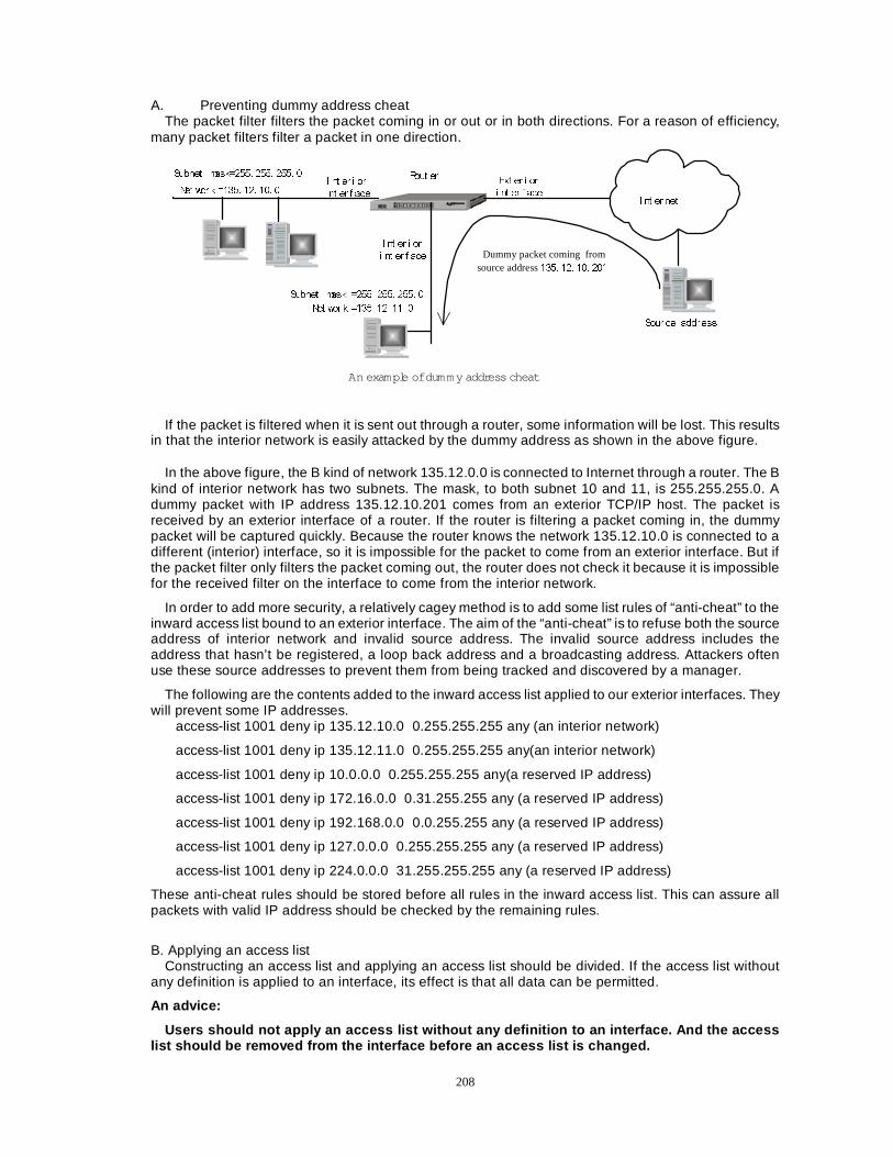
208
A. Preventing dummy address cheat The packet filter filters the packet coming in or out or in both directions. For a reason of efficiency,
many packet filters filter a packet in one direction.
, QW HUQHW
6XEQHW PDVN ���� ���� ���� �
1HW ZRU N ���� ��� ��� �
6XEQHW PDVN ���� ���� ���� �
1HW ZRU N ���� ��� ��� �
5RXW HU, QW HU L RU
L QW HU I DFH
([W HU L RU
L QW HU I DFH
6RXU FH DGGUHVV
Dummy packet coming fromsource address ���� ��� ��� ���
An example of dum m y addr ess cheat
, QW HU L RU
L QW HU I DFH
If the packet is filtered when it is sent out through a router, some information will be lost. This results in that the interior network is easily attacked by the dummy address as shown in the above figure.
In the above figure, the B kind of network 135.12.0.0 is connected to Internet through a router. The B kind of interior network has two subnets. The mask, to both subnet 10 and 11, is 255.255.255.0. A dummy packet with IP address 135.12.10.201 comes from an exterior TCP/IP host. The packet is received by an exterior interface of a router. If the router is filtering a packet coming in, the dummy packet will be captured quickly. Because the router knows the network 135.12.10.0 is connected to a different (interior) interface, so it is impossible for the packet to come from an exterior interface. But if the packet filter only filters the packet coming out, the router does not check it because it is impossible for the received filter on the interface to come from the interior network.
In order to add more security, a relatively cagey method is to add some list rules of “anti-cheat” to the inward access list bound to an exterior interface. The aim of the “anti-cheat” is to refuse both the source address of interior network and invalid source address. The invalid source address includes the address that hasn’t be registered, a loop back address and a broadcasting address. Attackers often use these source addresses to prevent them from being tracked and discovered by a manager.
The following are the contents added to the inward access list applied to our exterior interfaces. They will prevent some IP addresses.
access-list 1001 deny ip 135.12.10.0 0.255.255.255 any (an interior network)
access-list 1001 deny ip 135.12.11.0 0.255.255.255 any(an interior network)
access-list 1001 deny ip 10.0.0.0 0.255.255.255 any(a reserved IP address)
access-list 1001 deny ip 172.16.0.0 0.31.255.255 any (a reserved IP address)
access-list 1001 deny ip 192.168.0.0 0.0.255.255 any (a reserved IP address)
access-list 1001 deny ip 127.0.0.0 0.255.255.255 any (a reserved IP address)
access-list 1001 deny ip 224.0.0.0 31.255.255.255 any (a reserved IP address)
These anti-cheat rules should be stored before all rules in the inward access list. This can assure all packets with valid IP address should be checked by the remaining rules.
B. Applying an access list
Constructing an access list and applying an access list should be divided. If the access list without any definition is applied to an interface, its effect is that all data can be permitted.
An advice:
Users should not apply an access list without any definition to an interface. And the access list should be removed from the interface before an access list is changed.
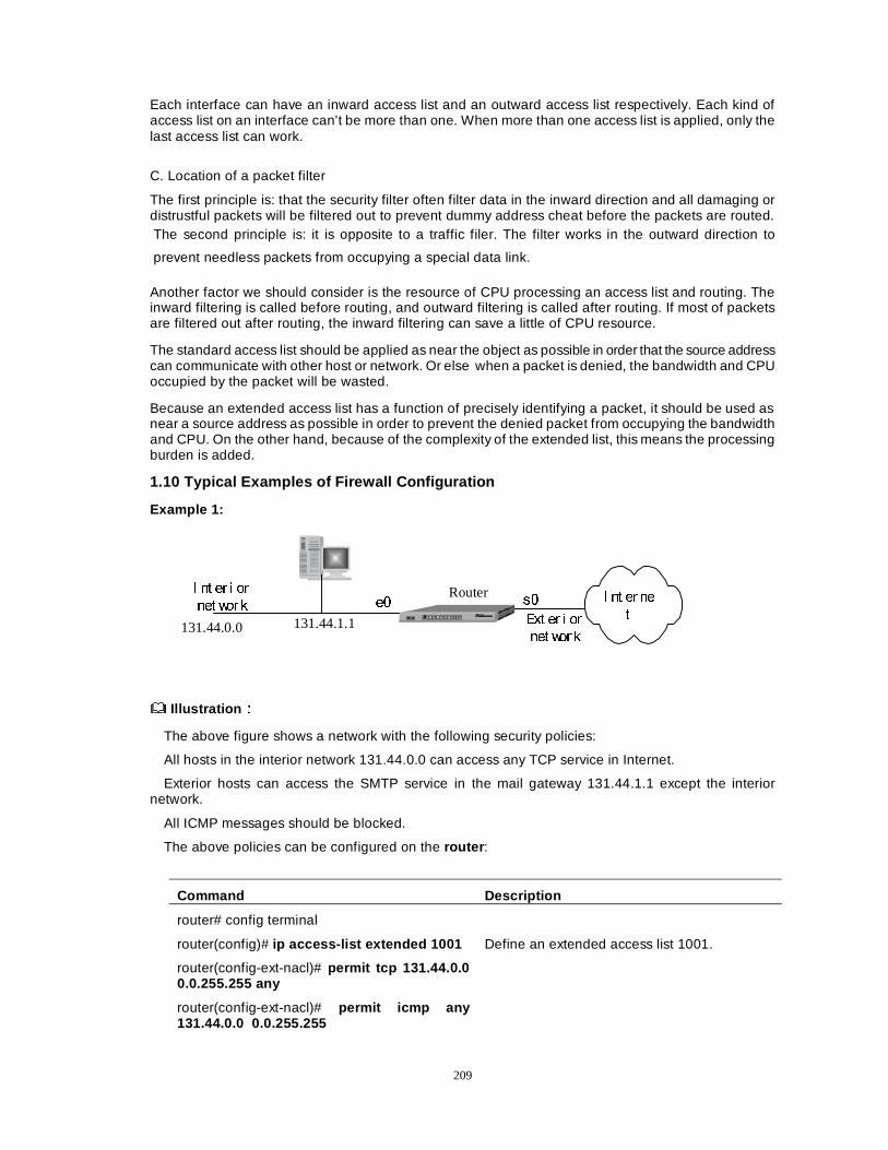
209
Each interface can have an inward access list and an outward access list respectively. Each kind of access list on an interface can’t be more than one. When more than one access list is applied, only the last access list can work.
C. Location of a packet filter
The first principle is: that the security filter often filter data in the inward direction and all damaging or distrustful packets will be filtered out to prevent dummy address cheat before the packets are routed. The second principle is: it is opposite to a traffic filer. The filter works in the outward direction to
prevent needless packets from occupying a special data link.
Another factor we should consider is the resource of CPU processing an access list and routing. The inward filtering is called before routing, and outward filtering is called after routing. If most of packets are filtered out after routing, the inward filtering can save a little of CPU resource.
The standard access list should be applied as near the object as possible in order that the source address can communicate with other host or network. Or else when a packet is denied, the bandwidth and CPU occupied by the packet will be wasted.
Because an extended access list has a function of precisely identifying a packet, it should be used as near a source address as possible in order to prevent the denied packet from occupying the bandwidth and CPU. On the other hand, because of the complexity of the extended list, this means the processing burden is added.
1.10 Typical Examples of Firewall Configuration
Example 1:
, QW HU QH
W([W HU L RU
QHW ZRU N
, QW HU L RU
QHW ZRU N
131.44.0.0 131.44.1.1
RouterH� V�
Illustration ÛÛ
The above figure shows a network with the following security policies:
All hosts in the interior network 131.44.0.0 can access any TCP service in Internet.
Exterior hosts can access the SMTP service in the mail gateway 131.44.1.1 except the interior network.
All ICMP messages should be blocked.
The above policies can be configured on the router :
Command Description
router# config terminal
router(config)# ip access-list extended 1001 Define an extended access list 1001.
router(config-ext-nacl)# permit tcp 131.44.0.0 0.0.255.255 any
router(config-ext-nacl)# permit icmp any 131.44.0.0 0.0.255.255
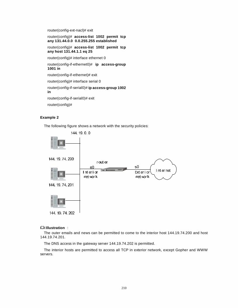
210
router(config-ext-nacl)# exit
router(config)# access-list 1002 permit tcp any 131.44.0.0 0.0.255.255 established
router(config)# access-list 1002 permit tcp any host 131.44.1.1 eq 25
router(config)# interface ethernet 0
router(config-if-ethernet0)# ip access-group 1001 in
router(config-if-ethernet)# exit
router(config)# interface serial 0
router(config-if-serial0)# ip access-group 1002 in
router(config-if-serial0)# exit
router(config)#
Example 2
The following figure shows a network with the security policies:
, QW HU QHW
U RXW HU
���� ��� �� �
���� ��� ��� ���
���� ��� ��� ���
���� ��� ��� ���
, QW HU L RU
QHW ZRU N
([W HU L RU
QHW ZRU N
H� V�
Illustration ÛÛ The outer emails and news can be permitted to come to the interior host 144.19.74.200 and host
144.19.74.201.
The DNS access in the gateway server 144.19.74.202 is permitted.
The interior hosts are permitted to access all TCP in exterior network, except Gopher and WWW servers.
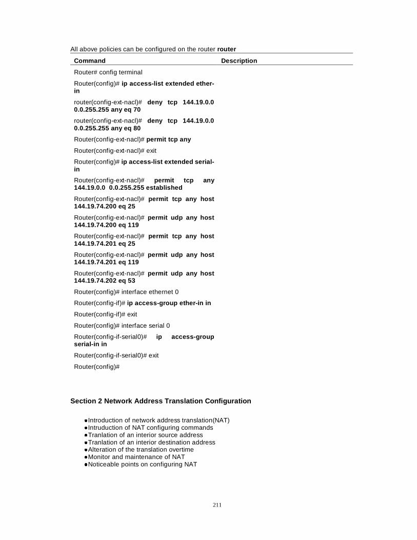
211
All above policies can be configured on the router router �
Command Description
Router# config terminal
Router(config)# ip access-list extended ether-in
router(config-ext-nacl)# deny tcp 144.19.0.0 0.0.255.255 any eq 70
router(config-ext-nacl)# deny tcp 144.19.0.0 0.0.255.255 any eq 80
Router(config-ext-nacl)# permit tcp any
Router(config-ext-nacl)# exit
Router(config)# ip access-list extended serial-in
Router(config-ext-nacl)# permit tcp any 144.19.0.0 0.0.255.255 established
Router(config-ext-nacl)# permit tcp any host 144.19.74.200 eq 25
Router(config-ext-nacl)# permit udp any host 144.19.74.200 eq 119
Router(config-ext-nacl)# permit tcp any host 144.19.74.201 eq 25
Router(config-ext-nacl)# permit udp any host 144.19.74.201 eq 119
Router(config-ext-nacl)# permit udp any host 144.19.74.202 eq 53
Router(config)# interface ethernet 0
Router(config-if)# ip access-group ether-in in
Router(config-if)# exit
Router(config)# interface serial 0
Router(config-if-serial0)# ip access-group serial-in in
Router(config-if-serial0)# exit
Router(config)#
Section 2 Network Address Translation Configuration
�Introduction of network address translation(NAT) �Intruduction of NAT configuring commands �Tranlation of an interior source address �Tranlation of an interior destination address �Alteration of the translation overtime �Monitor and maintenance of NAT �Noticeable points on configuring NAT
212
2.1 Intruduction of NAT
Network address translation (NAT) is mainly used to finish the translation between the local address and the global address. NAT has resolved the problem of Internet addresses exhaustion. The interior network of an enterprise only needs such a few of global addresses as to connect to Internet. NAT has also resolved TCP load assignment, which enhances the system performance.
A noticeable merit of NAT is that configuring NAT only needs to change a few of routers, which are used to configure NAT, and other hosts or routers don’t need to be altered.
NAT permits a special interior network whose IP address has not be registered to connect with Internet. NAT is configured on an edge router between an interior network and an exterior network like Internet. NAT translates the local address into an exclusive address in the world before a packet is sent out to an exterior network.
In order that NAT configuration can be understood better, some relative terms are defined firstly. Interior local address—It is an IP address in an interior network, and the address may not be a legal IP address provided by Network Information Center (NIC) or Internet Service Provider (ISP). Interior global address—It is a legal IP address (provided by NIC or ISP). It is used to represent one or more interior local IP address.
2.2 Introduction of NAT Configuring Commands
router (config)#ip nat ?
Command Description
frequency NAT translation overtime
inside Interior address translation
pool Define an IP address pool.
redirect-enable Open NAT redirection function.
translation Alter NAT translation overtime.
Define an IP address pool with the global configuring command ip nat pool.
Delete the pool with the command format: no ip nat poo l.
router(config)#ip nat pool name start-ip end-ip {netmask netmask | prefix-length prefix-length} [type rotary ]
Parameter Description
Name The name of the pool
start-ip The start address
end-ip The end address
Netmask Network mask
prefix-length The digits of the network mask that specifies the network mask to which all addresses in the pool belong.
type rotary It indicates that the address scope in the pool is true hosts addresses. A TCP load will be assigned on these hosts. (Optional) This type of address pool is only applied to NAT configuration of the interior destination address.
Command Description
router(config)#no ip nat pool name Delete the address pool.
213
NoteÛÛ A same address pool cannot be referred to by two different NAT configurations. If it is necessary, two
NAT definitions must be incorporated together, namely altering the corresponding access list rules. A same address cannot be defined in two different pools in order to avoid some unpredictable errors.
· Start an interior source address NAT with the global configuring command ip nat inside source .
Delete a static or dynamic translation with the command format no . Construct a basic static translation with the key static .
router(config)#ip nat inside source list {access-list-number | name} pool name [overload ]
Parameter Description
access-list-number The name/number of an access list
name The name of an address pool
overload Enable the router to use a global address for many local addresses. When the overload is configured, the port number of TCP or UDP in each interior host is used to distinguish between many sessions which use a same local IP address.�2SWLRQDO�
router(config)#ip nat inside source static {tcp | udp} local-ip local-port global-ip global-port
Parameter Description
local-ip The interior local address
global-ip The interior global address
tcp | udp Protocol
local-port The interior local port number
global-port The interior global port number
Start using NAT of the interior destination address with the global configuring command ip nat inside destination . Delete a dynamic translation with the command format “no”.
NAT of the interior destination address is used to share in TCP load.
router(config)#ip nat inside destination list {access-list-number | name} pool name
Parameter Description
Pool name It is the pool name. The pool contains a local address assigned in the dynamic translation. The pool type is ROTARY, and the address of the pool is a true interior address of local host.
Designate an interior/exterior interface of NAT with the interface configuring command ip nat . Remove the NAT function of the interface with the command format “no”.
Notice : An interface can’t be an interior interface and exterior interface at the same time.
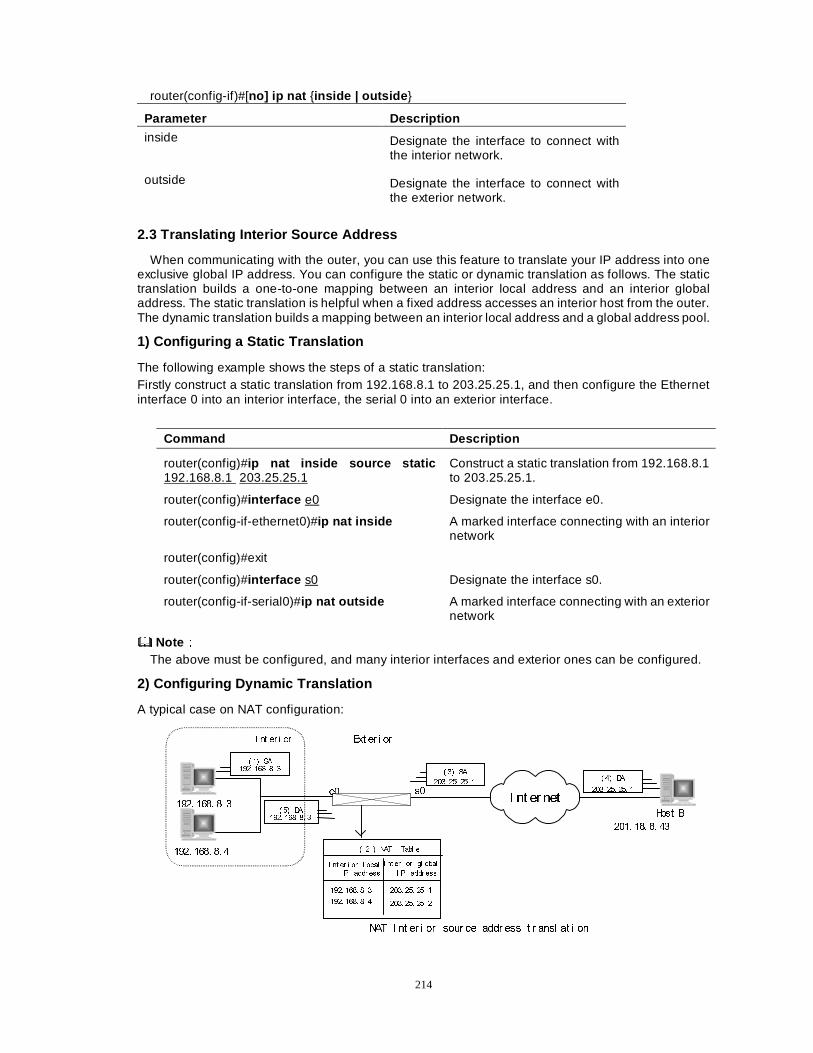
214
router(config-if)#[no] ip nat {inside | outside }
Parameter Description
inside Designate the interface to connect with the interior network.
outside Designate the interface to connect with the exterior network.
2.3 Translating Interior Source Address
When communicating with the outer, you can use this feature to translate your IP address into one exclusive global IP address. You can configure the static or dynamic translation as follows. The static translation builds a one-to-one mapping between an interior local address and an interior global address. The static translation is helpful when a fixed address accesses an interior host from the outer. The dynamic translation builds a mapping between an interior local address and a global address pool.
1) Configuring a Static Translation
The following example shows the steps of a static translation: Firstly construct a static translation from 192.168.8.1 to 203.25.25.1, and then configure the Ethernet interface 0 into an interior interface, the serial 0 into an exterior interface.
Command Description
router(config)#ip nat inside source static 192.168.8.1 203.25.25.1
Construct a static translation from 192.168.8.1 to 203.25.25.1.
router(config)#interface e0 Designate the interface e0.
router(config-if-ethernet0)#ip nat inside A marked interface connecting with an interior network
router(config)#exit
router(config)#interface s0 Designate the interface s0.
router(config-if-serial0)#ip nat outside A marked interface connecting with an exterior network
NoteÛÛ The above must be configured, and many interior interfaces and exterior ones can be configured.
2) Configuring Dynamic Translation
A typical case on NAT configuration:
, QW HU QHW���� ���� �� �
+RVW %
���� ��� �� ��
���� ���� �� �
, QW HU L RU ([W HU L RU
V�
� �� 6$
���� ��� ��� �
H�
� �� '$���� ���� �� �
� �� '$
���� ��� ��� �
1$7 , QW HU L RU VRXU FH DGGU HVV W U DQVO DW L RQ
� �� 6$���� ���� �� �
É�Ê 1$7 7DEO H
, QW HU L RU O RFDO, 3 DGGU HVV
, QW HU L RU JO REDO
, 3 DGGU HVV
���� ���� �� �
���� ���� �� �
���� ��� ��� �
���� ��� ��� �
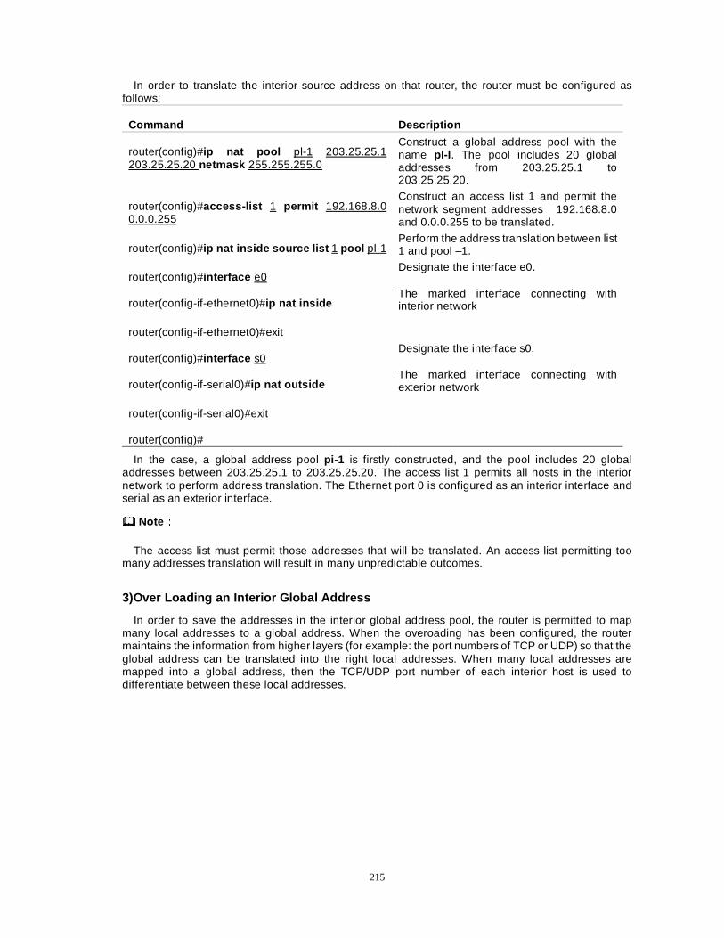
215
In order to translate the interior source address on that router, the router must be configured as follows:
Command Description
router(config)#ip nat pool pl-1 203.25.25.1 203.25.25.20 netmask 255.255.255.0
Construct a global address pool with the name pl-l . The pool includes 20 global addresses from 203.25.25.1 to 203.25.25.20.
router(config)#access-list 1 permit 192.168.8.0 0.0.0.255
Construct an access list 1 and permit the network segment addresses 192.168.8.0 and 0.0.0.255 to be translated.
router(config)#ip nat inside source list 1 pool pl-1 Perform the address translation between list 1 and pool –1.
router(config)#interface e0 Designate the interface e0.
router(config-if-ethernet0)#ip nat inside The marked interface connecting with interior network
router(config-if-ethernet0)#exit
router(config)#interface s0 Designate the interface s0.
router(config-if-serial0)#ip nat outside The marked interface connecting with exterior network
router(config-if-serial0)#exit
router(config)#
In the case, a global address pool pi-1 is firstly constructed, and the pool includes 20 global addresses between 203.25.25.1 to 203.25.25.20. The access list 1 permits all hosts in the interior network to perform address translation. The Ethernet port 0 is configured as an interior interface and serial as an exterior interface.
NoteÛÛ
The access list must permit those addresses that will be translated. An access list permitting too many addresses translation will result in many unpredictable outcomes.
3)Over Loading an Interior Global Address
In order to save the addresses in the interior global address pool, the router is permitted to map many local addresses to a global address. When the overoading has been configured, the router maintains the information from higher layers (for example: the port numbers of TCP or UDP) so that the global address can be translated into the right local addresses. When many local addresses are mapped into a global address, then the TCP/UDP port number of each interior host is used to differentiate between these local addresses.
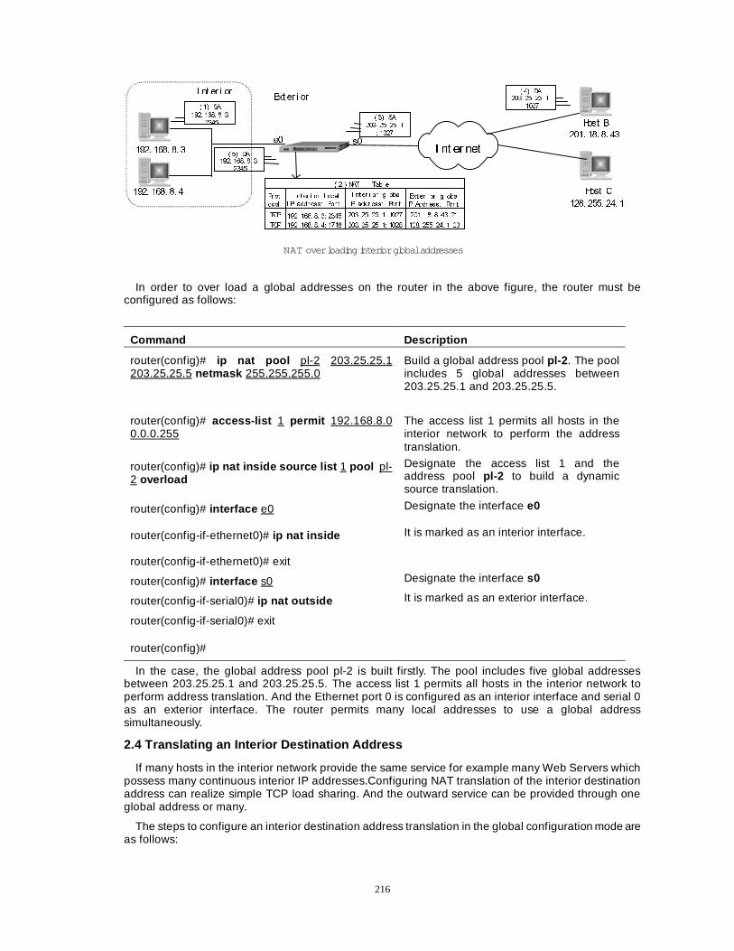
216
, QW HU QHW���� ���� �� �
+RVW %
���� ��� �� ��
���� ���� �� �
, QW HU L RU([W HU L RU
V�
� �� 6$���� ��� ��� �
� ����H�
� �� '$���� ���� �� �
� ����
� �� '$���� ��� ��� �
� ����
É�Ê1$7 7DEO H
, QW HU L RU O RFDO
, 3 DGGU HVV� 3RU W
, QW HU L RU JO REDO
, 3 DGGU HVV� 3RU W
���� ���� �� �� ����
���� ���� �� �� ����
���� ��� ��� �� ����
���� ��� ��� �� ����
NAT over loading inter ior global addresses
+RVW &
���� ���� ��� �([W HU L RU JO REDO
, 3 $GGU HVV� 3RU W
���� ��� �� ��� ��
���� ���� ��� �� ��
3U RW
RFRO
7&3
7&3
� �� 6$
���� ���� �� �� ����
In order to over load a global addresses on the router in the above figure, the router must be configured as follows:
Command Description
router(config)# ip nat pool pl-2 203.25.25.1 203.25.25.5 netmask 255.255.255.0
Build a global address pool pl-2 . The pool includes 5 global addresses between 203.25.25.1 and 203.25.25.5.
router(config)# access-list 1 permit 192.168.8.0 0.0.0.255
The access list 1 permits all hosts in the interior network to perform the address translation.
router(config)# ip nat inside source list 1 pool pl-2 overload
Designate the access list 1 and the address pool pl-2 to build a dynamic source translation.
router(config)# interface e0 Designate the interface e0
router(config-if-ethernet0)# ip nat inside It is marked as an interior interface.
router(config-if-ethernet0)# exit
router(config)# interface s0 Designate the interface s0
router(config-if-serial0)# ip nat outside It is marked as an exterior interface.
router(config-if-serial0)# exit
router(config)#
In the case, the global address pool pl-2 is built firstly. The pool includes five global addresses between 203.25.25.1 and 203.25.25.5. The access list 1 permits all hosts in the interior network to perform address translation. And the Ethernet port 0 is configured as an interior interface and serial 0 as an exterior interface. The router permits many local addresses to use a global address simultaneously.
2.4 Translating an Interior Destination Address
If many hosts in the interior network provide the same service for example many Web Servers which possess many continuous interior IP addresses.Configuring NAT translation of the interior destination address can realize simple TCP load sharing. And the outward service can be provided through one global address or many.
The steps to configure an interior destination address translation in the global configuration mode are as follows:
217
A. Define a rotary type of an IP address pool that can be assigned when needed. The addresses in the pool are the interior host addresses used to share in TCP load.
router(config)#ip nat pool name start-ip end-ip {netmask netmask | prefix-length prefix-length} type rotary
Parameter Description
Name The pool name
start-ip The start address
end-ip The end address
netmask Network mask
prefix-length The bit number of the mask
type rotary Express it is a true host.
B. Define an access list and permit these addresses to be translated.
router (config)#access-list access-list-number permit source source-wildcard access-list access-list-number permit protocol source source-wildcard destination destination-wildcard [precedence precedence] [tos tos] [log]
The above are the definitions of both a standard access list and an extension access list. The concrete syntax can be referred to in the instructions of firewall configuration. Generally, this can be defined as an extension access list so as to limit the destination address of received datagram. Only when the destination address of the datagram the exterior interface received is opened, can the datagram be translated.
C. Construct an interior destination translation through the access list and the address pool the above steps specified.
Command Description
ip nat inside destination list access-list-number pool name
D. Designate an interior interface.
Command Description
interface type number
E. Mark the interface to connect with the interior.
Command Description
ip nat inside
F. Designate an exterior interface.
Command Description
interface type number
G. Mark the interface to connect with the exterior.
Command Description
ip nat outside
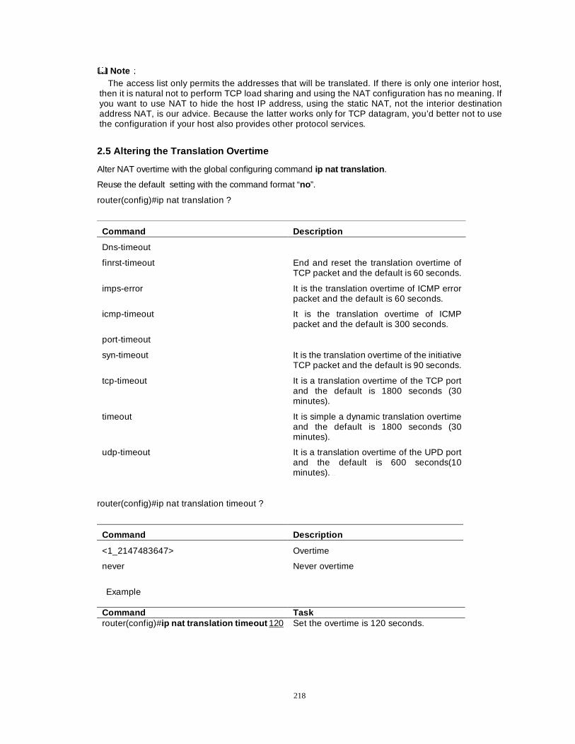
218
NoteÛÛ The access list only permits the addresses that will be translated. If there is only one interior host,
then it is natural not to perform TCP load sharing and using the NAT configuration has no meaning. If you want to use NAT to hide the host IP address, using the static NAT, not the interior destination address NAT, is our advice. Because the latter works only for TCP datagram, you’d better not to use the configuration if your host also provides other protocol services.
2.5 Altering the Translation Overtime
Alter NAT overtime with the global configuring command ip nat translation .
Reuse the default setting with the command format “no”.
router(config)#ip nat translation ?
Command Description
Dns-timeout
finrst-timeout End and reset the translation overtime of TCP packet and the default is 60 seconds.
imps-error It is the translation overtime of ICMP error packet and the default is 60 seconds.
icmp-timeout It is the translation overtime of ICMP packet and the default is 300 seconds.
port-timeout
syn-timeout It is the translation overtime of the initiative TCP packet and the default is 90 seconds.
tcp-timeout It is a translation overtime of the TCP port and the default is 1800 seconds (30 minutes).
timeout It is simple a dynamic translation overtime and the default is 1800 seconds (30 minutes).
udp-timeout It is a translation overtime of the UPD port and the default is 600 seconds(10 minutes).�
router(config)#ip nat translation timeout ?
Command Description
<1_2147483647> Overtime
never Never overtime
Example
Command Task router(config)#ip nat translation timeout 120 Set the overtime is 120 seconds.
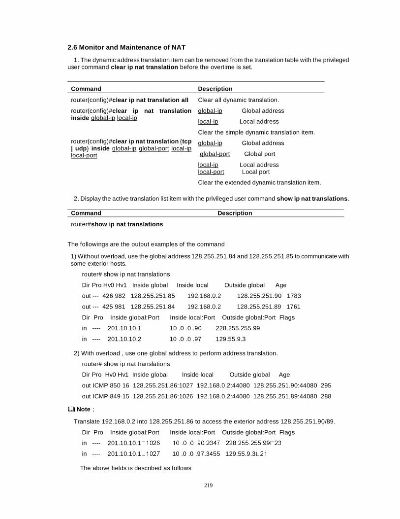
219
2.6 Monitor and Maintenance of NAT
1. The dynamic address translation item can be removed from the translation table with the privileged user command clear ip nat translation before the overtime is set.
Command Description
router(config)#clear ip nat translation all Clear all dynamic translation.
router(config)#clear ip nat translation inside global-ip local-ip
global-ip Global address
local-ip Local address
Clear the simple dynamic translation item.
router(config)#clear ip nat translation {tcp | udp } inside global-ip global-port local-ip local-port
global-ip Global address
global-port Global port
local-ip Local address local-port Local port
Clear the extended dynamic translation item.
2. Display the active translation list item with the privileged user command show ip nat translations .
Command Description
router#show ip nat translations
The followings are the output examples of the commandÛ
1) Without overload, use the global address 128.255.251.84 and 128.255.251.85 to communicate with some exterior hosts.
router# show ip nat translations
Dir Pro Hv0 Hv1 Inside global Inside local Outside global Age
out --- 426 982 128.255.251.85 192.168.0.2 128.255.251.90 1783
out --- 425 981 128.255.251.84 192.168.0.2 128.255.251.89 1761
Dir Pro Inside global:Port Inside local:Port Outside global:Port Flags
in ---- 201.10.10.1 10 .0 .0 .90 228.255.255.99
in ---- 201.10.10.2 10 .0 .0 .97 129.55.9.3
2) With overload , use one global address to perform address translation.
router# show ip nat translations
Dir Pro Hv0 Hv1 Inside global Inside local Outside global Age
out ICMP 850 16 128.255.251.86:1027 192.168.0.2:44080 128.255.251.90:44080 295
out ICMP 849 15 128.255.251.86:1026 192.168.0.2:44080 128.255.251.89:44080 288
NoteÛÛ
Translate 192.168.0.2 into 128.255.251.86 to access the exterior address 128.255.251.90/89.
Dir Pro Inside global:Port Inside local:Port Outside global:Port Flags
in ---- 201.10.10.1����� �� �� �� �������� �����������������
in ---- 201.10.10.1����� 10 .0 .0 .97.3455 129.55.9.3���
The above fields is described as follows
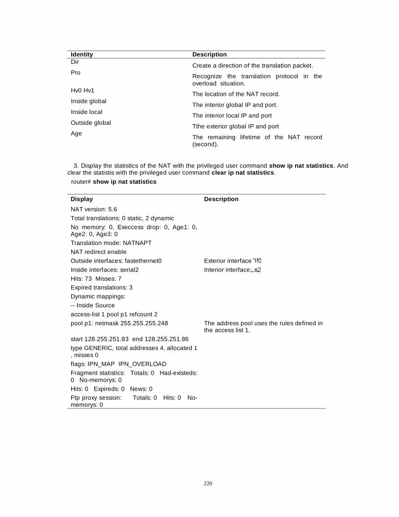
220
Identity Description Dir
Create a direction of the translation packet. Pro
Recognize the translation protocol in the overload situation.
Hv0 Hv1 The location of the NAT record.
Inside global The interior global IP and port.
Inside local The interior local IP and port
Outside global Tthe exterior global IP and port
Age The remaining lifetime of the NAT record (second).
3. Display the statistics of the NAT with the privileged user command show ip nat statistics . And clear the statistis with the privileged user command clear ip nat statistics .
router# show ip nat statistics Display Description
NAT version: 5.6
Total translations: 0 static, 2 dynamic
No memory: 0, Execcess drop: 0, Age1: 0, Age2: 0, Age3: 0
Translation mode: NATNAPT
NAT redirect enable
Outside interfaces: fastethernet0 Exterior interface�I�
Inside interfaces: serial2 Interior interface�V�
Hits: 73 Misses: 7 Expired translations: 3
Dynamic mappings:
-- Inside Source
access-list 1 pool p1 refcount 2
pool p1: netmask 255.255.255.248 The address pool uses the rules defined in the access list 1.
start 128.255.251.83 end 128.255.251.86
type GENERIC, total addresses 4, allocated 1 , misses 0
flags: IPN_MAP IPN_OVERLOAD
Fragment statistics: Totals: 0 Had-existeds: 0 No-memorys: 0
Hits: 0 Expireds: 0 News: 0 Ftp proxy session: Totals: 0 Hits: 0 No-memorys: 0
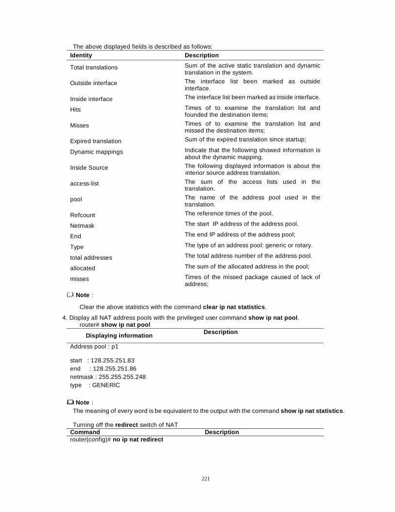
221
The above displayed fields is described as follows: Identity Description
Total translations Sum of the active static translation and dynamic translation in the system.
Outside interface The interface list been marked as outside interface.
Inside interface The interface list been marked as inside interface.
Hits Times of to examine the translation list and founded the destination items;
Misses Times of to examine the translation list and missed the destination items;
Expired translation Sum of the expired translation since startup;
Dynamic mappings Indicate that the following showed information is about the dynamic mapping.
Inside Source The following displayed information is about the interior source address translation.
access-list The sum of the access lists used in the translation.
pool The name of the address pool used in the translation.
Refcount The reference times of the pool.
Netmask The start IP address of the address pool.
End The end IP address of the address pool;
Type The type of an address pool: generic or rotary.
total addresses The total address number of the address pool.
allocated The sum of the allocated address in the pool;
misses Times of the missed package caused of lack of address;
NoteÛÛ
Clear the above statistics with the command clear ip nat statistics .
4. Display all NAT address pools with the privileged user command show ip nat pool . router# show ip nat pool
Displaying information Description
Address pool : p1
start : 128.255.251.83 end : 128.255.251.86 netmask : 255.255.255.248 type : GENERIC
NoteÛÛ The meaning of every word is be equivalent to the output with the command show ip nat statistics .
Turning off the redirect switch of NAT
Command Description router(config)# no ip nat redirect
222
NoteÛÛ The switch redirect is a switch specially set by NAT for OICQ application. The particularity of the
OICQ application results in the users between the interior network and exterior network can’t communicate with each other directly. The transference of the OICQ server can resolve the problem. NAT of an ROUTER provides the special switch function based on the application to realize the direct communication between users.
The default configuration of the switch is ON. If you don’t need the function, you can turn off the
switch. Open the switch again with the following command: Command Description
router(config)# ip nat redirect
2.7 Noticeable Points on Configuring NAT
1. The global IP address and the local IP address cannot be overlapped. Three kinds of local addresses are recommended:
Kind Description
A class-10.0.0.0 / 8 1 A class IP address
B class-172.16.0.0 / 12 16 B class IP addresses
C class-192.168.0.0 / 16 256 C class IP addresses
2.The static address and the address of the dynamic address pool cannot be overlapped.
3. As a solution for the connection problem, NAT is practical when quite a few of hosts communicate with the exterior simultaneously. In this case, only quite a few subset of the address scope must be translated to an exclusive address in the world when the communication with the exterior is necessary. When these addresses arent’s used any morer, these addresses can be reused.
4. When an IP address or a port is embedded in an application program, NAT, to users of the opposing ends, isn’t transparent. So NAT can’t be used in the case.
5. The router that has utilized NAT doesn’t support IPSEC because the security of point to point can’t be guaranteed.
6. The routing information broadcasts only inward direction, not outward direction.
7. The static routing configuration between NAT and ISP router need to be set;
8. IP OPTION doesn’t be supported normally.
9. When many interfaces exist, the same NAT list should be used.
223
Section 3 Easy IP Configuration
� Introduction of Easy IP � Easy IP configuration
3.1 Introduction of Easy IP
The speciality of Easy IP is to combine network address translation (NAT) and PPP/PCP together. This makes the router to negotiate automatically with the center server on the registered IP address of the WAN interface and all remote hosts can use the single registered IP address to access Internet. Because Easy IP has applied the multiple-utilization NAT at the port level, the IP address in the remote LAN is invisible in Internet.
Applying Easy IP has the following benefits:
IP address being assigned dynamically cuts the cost of access Internet. Router configuration and IP address management been simplified. Assign IP address to remote workstation dynamically. Secreted the remote LAN IP address.
NoteÛÛ
In order to make Easy IP works normally, the static routing from LAN to WAN should also be configured.
3.2 Easy IP Configuration
Main contents of Easy IP are: A. Configuration task list of Easy IP; B. Easy IP configuration case Task list configuration of Easy IP:
1) Define a NAT pool, 2) Configure LAN interface, 3) Define NAT for a LAN interface, 4) Configure WAN interface, 5) Define NAT for WAN interface.
Easy IP configuration case The following configuration can make many hosts in the interior network to use only one negotiated IP address to access Internet.
Command Description
router(config)# access-list 1 permit 192.168.12.0 0.0.0.255
Define access list 1 and enable it to permit the addresses in the network segment can be translated.
router(config)# ip nat inside source list 1 interface serial0 overload
The dynamic source address translation is built between the access list 1 and the port s0.
router(config)# interface e0 Designate a LAN interface e0.
router(config-if-ethernet0)# ip address 192.168.12.1 255.255.255.0
router(config-if-ethernet0)# ip nat inside Define NAT for LAN interface.
router(config-if-ethernet)# exit
router(config)# interface s0 Designate WAN interface s0.
router(config-if-serial0)# physical-layer async
router(config-if-serial0)# speed 38400
router(config-if-serial0)# flow-control hardware
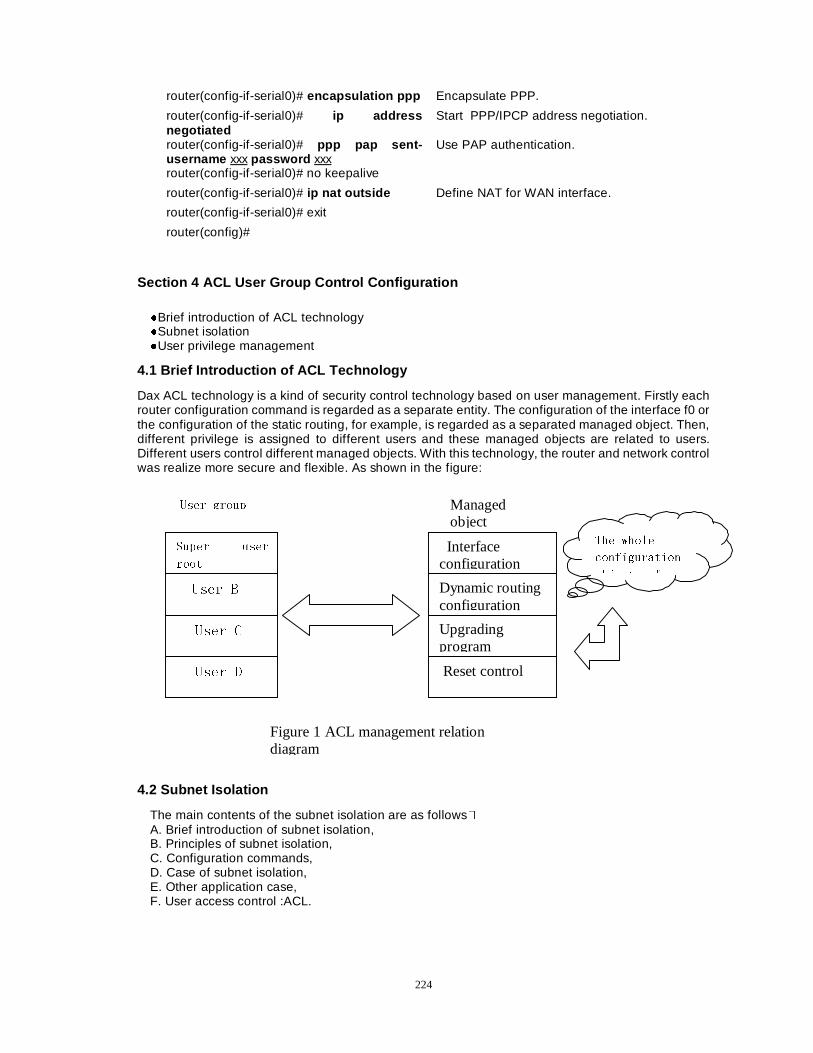
224
router(config-if-serial0)# encapsulation ppp Encapsulate PPP.
router(config-if-serial0)# ip address negotiated
Start PPP/IPCP address negotiation.
router(config-if-serial0)# ppp pap sent-username xxx password xxx
Use PAP authentication.
router(config-if-serial0)# no keepalive
router(config-if-serial0)# ip nat outside Define NAT for WAN interface.
router(config-if-serial0)# exit
router(config)#
Section 4 ACL User Group Control Configuration
�Brief introduction of ACL technology �Subnet isolation �User privilege management
4.1 Brief Introduction of ACL Technology
Dax ACL technology is a kind of security control technology based on user management. Firstly each router configuration command is regarded as a separate entity. The configuration of the interface f0 or the configuration of the static routing, for example, is regarded as a separated managed object. Then, different privilege is assigned to different users and these managed objects are related to users. Different users control different managed objects. With this technology, the router and network control was realize more secure and flexible. As shown in the figure:
4.2 Subnet Isolation
The main contents of the subnet isolation are as follows� A. Brief introduction of subnet isolation, B. Principles of subnet isolation, C. Configuration commands, D. Case of subnet isolation, E. Other application case, F. User access control :ACL.
6XSHU XVHU
URRW
8VHU %
8VHU &
8VHU '
8VHU JURXS
Interface configuration
Dynamic routing configuration
Upgrading program
Reset control
Managed object
7KH ZKROH
FRQILJXUDWLRQ
REMHFWV RI
Figure 1 ACL management relation diagram
225
A. Brief Introduction of Subnet Isolation
With the advent of the sub-interface technology, it becomes possible to constitute and retain multiple logical links on a single physical interface. ACL network security technology of Dax-Maipu provides a favorable measure on subnet security. Different access areas are partitioned and these access areas can’t communicate with each other. This ensures the security of data stream on the same sharing physical link.
B. Principles of Subnet Isolation
Different access areas are divided and these access areas can’t communicate each other. The access area is based on an interface. Through partitioning different access area, the function of subnet isolation can perform filtering on the interface. So the dummy source address attack can be prevented physically. Those access areas that can communicate with each other can be partitioned as a same access area. Users and datagram in other access areas can’t access this area. This can accomplish the different service isolation on the same sharing physical link.
C. Configuring Commands
Command Description
router (config)#acl-group number interface interface number
number <1����! Realize the binding of service area.ÄDefine an access group and an interface the group can access.Å
router (config)#acl-group number user user names
Accomplish the binding between a user and a local area. (Define a user of access group.�
routerA(config)#user root password 0 password
Set the super user.
router (config)#user usernames password 0 password
Set the common user.
NoteÛÛ The accounts of the super user can but are root.
zzOpening the function of user classification management
Command Description router (config)# service password-encryption
Open the service of password encryption.
router (config)# service enhanced-secure
Open the service of enhanced encryption.
NoteÛÛ After the command has been used, all passwords configured previously are shown in cipher text. So
make sure to remember the password of the super user root.
zzConfiguring local login authentication
Command Description
router (config)# aaa new-model Open the AAA function. router (config)# aaa authentication login default local
setup the local authentication mode.
NoteÛÛ
NoticeÛAfter the above commands are configured, the configured user name must be input for you to enter a common user mode again when you have exited from the common user mode. If the user root logs in, he can freely alter the router configuration If a common user logs in, he will be managed by corresponding grade.
226
zzForbidding second login of common user
Command Description
router (config)#no enable acl telnet-twice
NoteÛÛ
After the command has been configuredÍuser login again is forbidden when he has logged in a router.
zzGrant the common user partial right router (config)#acl username
Command Description
acl_ifgrp Permit setting acl right�Configure acl group and all ports of the group�
acl_usergrp Permit setting acl right�Configure acl group and all users of the group�
del_startup Assign the right to delete a configuration file.
interface Assign the right to operate ports.
line Assign the right to operate the asynchronous ports.
Reload Assign the right to reset.
sif_maker Assign the right to set sub-interface.
st_route Assign the right to set the static routing.
Sysupdate Assign the right to upgrade system.
NoteÛÛ Before the above commands are used, common users are prohibited to operate it. But after these
commands are used, they can be read/ written (only read or written, or both is optional).
D. An Example of Subnet Isolation
The figure illustrates a network with the following security policies:
Illustration ÛÛ After X25 is configured between the router B and the router C, we can accomplish the followings:
1. The user DaxA can’t access any interface and other equipment in the access area B, such as the server B.
2. The user DaxB can’t access any interface and other equipment in the access area A, such as the interface S1 in the router c .
3. That the user DaxA tries to log in to a router from the netB will be denied.
4. Users except the super user cannot telnet after they have telneted to a routerÉIt is optional
and it can prevent second loginÊ
The dataflow, which is based on port number or MAC address of a PC NIC(Network Interface Card), can be prohibited. For example�Iirstly use arp to bind the MAC address of a PC network card to an IP address, then define the dataflow of the IP address through a access list. In this way, This way to realized that except only one fixed PC can access the network segment, no any other PC can make it, even their IP address been modified.
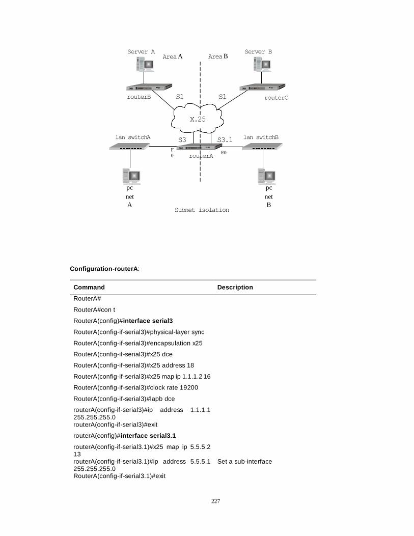
227
Area BArea A
netA
netB
F0
E0
Subnet isolation
pcpc
Server BServer A
routerA
routerB
lan switchA lan switchB
routerC
S3 S3.1
S1S1
X.25
Configuration-routerA :
Command Description
RouterA#
RouterA#con t
RouterA(config)#interface serial3
RouterA(config-if-serial3)#physical-layer sync
RouterA(config-if-serial3)#encapsulation x25
RouterA(config-if-serial3)#x25 dce
RouterA(config-if-serial3)#x25 address 18
RouterA(config-if-serial3)#x25 map ip 1.1.1.2 16
RouterA(config-if-serial3)#clock rate 19200
RouterA(config-if-serial3)#lapb dce
routerA(config-if-serial3)#ip address 1.1.1.1 255.255.255.0
routerA(config-if-serial3)#exit
routerA(config)#interface serial3.1
routerA(config-if-serial3.1)#x25 map ip 5.5.5.2 13
routerA(config-if-serial3.1)#ip address 5.5.5.1 255.255.255.0
Set a sub-interface
RouterA(config-if-serial3.1)#exit
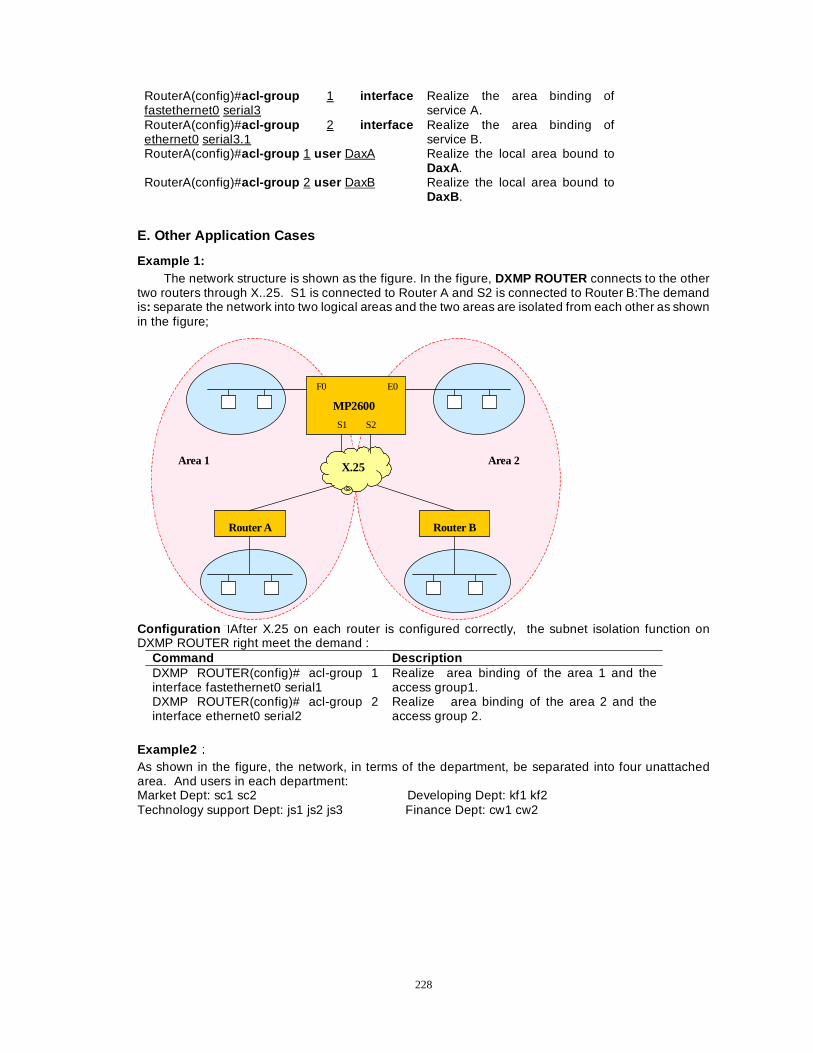
228
RouterA(config)#acl-group 1 interface fastethernet0 serial3
Realize the area binding of service A.
RouterA(config)#acl-group 2 interface ethernet0 serial3.1
Realize the area binding of service B.
RouterA(config)#acl-group 1 user DaxA Realize the local area bound to DaxA.
RouterA(config)#acl-group 2 user DaxB Realize the local area bound to DaxB .
E. Other Application Cases
Example 1: The network structure is shown as the figure. In the figure, DXMP ROUTER connects to the other
two routers through X..25. S1 is connected to Router A and S2 is connected to Router B:The demand is: separate the network into two logical areas and the two areas are isolated from each other as shown in the figure;
F0 E0
MP2600
S1 S2
Area 2 Area 1 X.25
Router B Router A
Configuration �After X.25 on each router is configured correctly, the subnet isolation function on DXMP ROUTER right meet the demand :
Command Description DXMP ROUTER(config)# acl-group 1 interface fastethernet0 serial1
Realize area binding of the area 1 and the access group1.
DXMP ROUTER(config)# acl-group 2 interface ethernet0 serial2
Realize area binding of the area 2 and the access group 2.
Example2ÛÛ As shown in the figure, the network, in terms of the department, be separated into four unattached area. And users in each department: Market Dept: sc1 sc2 Developing Dept: kf1 kf2 Technology support Dept: js1 js2 js3 Finance Dept: cw1 cw2
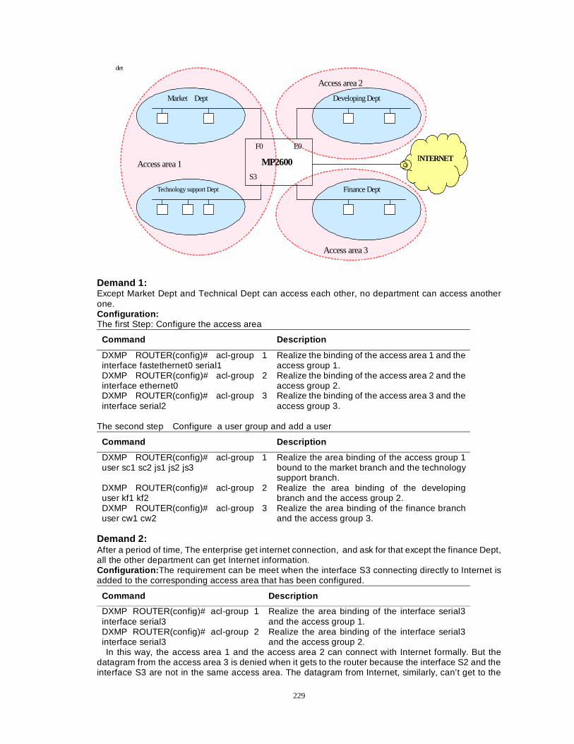
229
det
F0 E0
MP2600
S3
Market Dept
Technology support Dept
Developing Dept
Finance Dept
Access area 2
Access area 1
Access area 3
INTERNET
Demand 1: Except Market Dept and Technical Dept can access each other, no department can access another one. Configuration: The first Step: Configure the access area
Command Description
DXMP ROUTER(config)# acl-group 1 interface fastethernet0 serial1
Realize the binding of the access area 1 and the access group 1.
DXMP ROUTER(config)# acl-group 2 interface ethernet0
Realize the binding of the access area 2 and the access group 2.
DXMP ROUTER(config)# acl-group 3 interface serial2
Realize the binding of the access area 3 and the access group 3.
The second step �Configure a user group and add a user
Command Description
DXMP ROUTER(config)# acl-group 1 user sc1 sc2 js1 js2 js3
Realize the area binding of the access group 1 bound to the market branch and the technology support branch.
DXMP ROUTER(config)# acl-group 2 user kf1 kf2
Realize the area binding of the developing branch and the access group 2.
DXMP ROUTER(config)# acl-group 3 user cw1 cw2
Realize the area binding of the finance branch and the access group 3.
Demand 2: After a period of time, The enterprise get internet connection, and ask for that except the finance Dept, all the other department can get Internet information. Configuration: The requirement can be meet when the interface S3 connecting directly to Internet is added to the corresponding access area that has been configured.
Command Description
DXMP ROUTER(config)# acl-group 1 interface serial3
Realize the area binding of the interface serial3 and the access group 1.
DXMP ROUTER(config)# acl-group 2 interface serial3
Realize the area binding of the interface serial3 and the access group 2.
In this way, the access area 1 and the access area 2 can connect with Internet formally. But the datagram from the access area 3 is denied when it gets to the router because the interface S2 and the interface S3 are not in the same access area. The datagram from Internet, similarly, can’t get to the
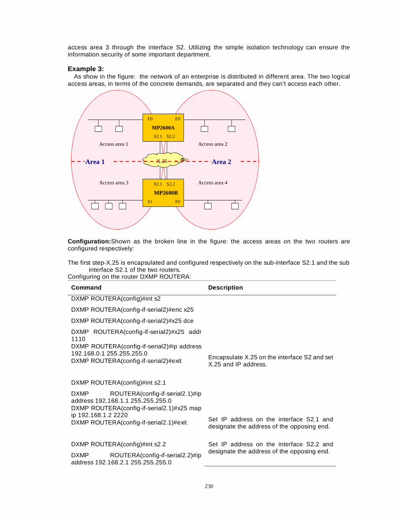
230
access area 3 through the interface S2. Utilizing the simple isolation technology can ensure the information security of some important department.
Example 3:
As show in the figure: the network of an enterprise is distributed in different area. The two logical access areas, in terms of the concrete demands, are separated and they can’t access each other.
F0 E0
MP2600A
S2.1 S2.2
Access area 2 Access area 1
S2.1 S2.2
MP2600B
S1 F0
X.25
Access area 3 Access area 4
Area 1 Area 2
Configuration: Shown as the broken line in the figure: the access areas on the two routers are configured respectively: The first step-X.25 is encapsulated and configured respectively on the sub-interface S2.1 and the sub
interface S2.1 of the two routers. Configuring on the router DXMP ROUTERA:
Command Description
DXMP ROUTERA(config)#int s2
DXMP ROUTERA(config-if-serial2)#enc x25
DXMP ROUTERA(config-if-serial2)#x25 dce
DXMP ROUTERA(config-if-serial2)#x25 addr 1110 DXMP ROUTERA(config-if-serial2)#ip address 192.168.0.1 255.255.255.0 DXMP ROUTERA(config-if-serial2)#exit
Encapsulate X.25 on the interface S2 and set X.25 and IP address.
DXMP ROUTERA(config)#int s2.1
DXMP ROUTERA(config-if-serial2.1)#ip address 192.168.1.1 255.255.255.0 DXMP ROUTERA(config-if-serial2.1)#x25 map ip 192.168.1.2 2220 DXMP ROUTERA(config-if-serial2.1)#exit Set IP address on the interface S2.1 and
designate the address of the opposing end.
DXMP ROUTERA(config)#int s2.2
DXMP ROUTERA(config-if-serial2.2)#ip address 192.168.2.1 255.255.255.0
Set IP address on the interface S2.2 and designate the address of the opposing end.
231
DXMP ROUTERA(config-if-serial2.2)#x25 map ip 192.168.2.2 2220 DXMP ROUTERA(config-if-serial2.2)#exit
Configuring on the router DXMP ROUTERB�
Command Description
DXMP ROUTERB(config)#int s2
DXMP ROUTERB(config-if-serial2)#enc x25
DXMP ROUTERB(config-if-serial2)#x25 dce
DXMP ROUTERB(config-if-serial2)#x25 addr 2220 DXMP ROUTERB(config-if-serial2)#ip address 192.168.0.2 255.255.255.0 DXMP ROUTERB(config-if-serial2)#exit
Encapsulate X.25 on the interface S2 and set X.25 and IP address.
DXMP ROUTERB(config)#int s2.1
DXMP ROUTERB(config-if-serial2.1)#ip address 192.168.1.2 255.255.255.0 DXMP ROUTERB(config-if-serial2.1)#x25 map ip 192.168.1.1 1110 DXMP ROUTERB(config-if-serial2.1)#exit Set IP address on the interface S2.1 and
designate the address of the opposing end.
DXMP ROUTERB(config)#int s2.2
DXMP ROUTERB(config-if-serial2.2)#ip address 192.168.2.2 255.255.255.0 DXMP ROUTERB(config-if-serial2.2)#x25 map ip 192.168.2.1 1110 DXMP ROUTERB(config-if-serial2.2)#exit Set IP address on the interface S2.1 and
designate the address of the opposing end. The second step �Setting an access area�
Command Description
DXMP ROUTERA(config)# acl-group 1 interface fastethernet0 serial2.1
Realize the area binding of the area 1 and the access group 1.
DXMP ROUTERA(config)# acl-group 2 interface ethernet0 serial2.2
Realize the area binding of the area 2 and the access group2.
DXMP ROUTERB(config)# acl-group 3 interface serial1 serial2.1
Realize the area binding of the area 3 and the access group 3.
DXMP ROUTERB(config)# acl-group 4 interface fastethernet0 serial2.2
Realize the area binding of the area 4 and the access group 4.
The third step�Adding a user to the user group in the corresponding access area.
Like case 2, add a user to the corresponding group: the users in the area 1 should be added to the group 1 and group 3, and the users in the area 2 to the group 2 and the group 4 (The details of the commands are omitted.
F. User Right Control ACL
You can configure whether a user is permitted to execute the Telnet two times on the router. The command is as follows:
232
Command Description
DXMP ROUTER(config)# enable acl telnet-twice Permit two time of Telnet
DXMP ROUTER(config)# no enable acl telnet-twice
Do not permit two times of Telnet
The system default is to permit. If you perform a configuration to permit two times of Telnet that can’t be permitted to execute twice, there are the following results: If the subnet isolation is configured in the system, the operation is permitted; If the user is Root the operation is permitted, or else it is prohibited.
4.3 User Rights Management
Managers at the different levels can have the responding rights, through the setup of user management rights. This can ensure the router run normally and be easy to maintain. The graded rights and the corresponding setup are shown as follows:
Command Description
router(config)user root password 0 router Set the super user and its account can only be root .
router(config)exit
router#exit
router>exit
Login:root
password:Dax “Dax” is not displayed
router>en
router#config terminal
router(config)user Dax password 0 Dax Add a new user and its password is Dax.
router(config)service password-encryption
router(config)service enhanced-secure Open the function of user grade management.
If root doesn’t perform any operation, Dax can only examine the configuration of the router and perform other operations that have no effect on the router operation.
router(config)# acl Dax :
Command Description
acl_ifgrp Assign the right to allow setting up acl .
acl_usergrp Assign the right to allow setting up acl .
address_set Assign the right to allow configuring an interface.
del_startup Assign the right to allow deleting configuration file.
reload Assign the right to allow reloading the system files.
sif_maker Assign the right to allow setting up the sub-interface.
st_route Assign the right to allow adding a static routing.
sysupdate Assign the right to allow upgrading system.
telnet_twice Assign the right to allow setting up second login.
Example:
Command Task
router(config)#acl Dax reload This command grants the user Dax the right to reset a router.
233
NoteÛÛ At first, only the user root can perform the operation acl and can alter the configuration freely on the router. So please fix the password of root in your mind.
Section 5 IPSec Network Security Configuration
Main contents of this sections: �Summary; �Configure IPSEC; �Monitor and debug IPSEC; �IPSEC configuration case .
5.1 Summary
The main contents of the summary are as follows� A. The security services provided by IPSEC B. The standard supported by IPSEC in software implementation C. Limitation
The detailed contents are as follows: A. The security services provided by IPSEC:
Data confidentiality ——The packet will be encrypted before IPSec sender transmits the packet through the network.
Data integrality——IPSec receiver will authenticate the packet from the sender to ensure the data packet should not be altered during the course of data transmission.
Data source authentication——IPSec receiver authenticates the source address of the IPSec packet. This service is based on the service of data integrality.
Anti-replay——IPSec receiver can check and reject the replayed packet. B. The following standards are supported by IPSec in software practice:
AH——Authentication header, a kind of protocol to provide data authentication service and an optional anti-replayed service. AH is embedded in the data that needs protection (a kind of an automatic addressing packet).
ESP——Encapsulating Security Payload, a kind of security protocol to provide data security service, an optional data authentication service and an anti-replay service. ESP will encapsulate the data that needs protection. The old versions of RFC 1829 ESP and the edited ESP have been realized.
C. Limitation So far, IPSEC can only used to work in Point to Point mode. . If NAT (Network Address Translation) is used, then NAT translation must be performed before the router encapsulates a packet. And IPSec should use the global address.
5.2 Configure IPSEC
Manual configuration of IPSec needs to finish the following configuration task on each IPSec peer that participates in communication. An IPSec configuring task list is introduced:A, IPSEC control configuration:B, creating an Encryption Access List:C, defining an encryption transform set; D, creating the encryption mapping item:E, configuring local lifetime:F, applying the encryption mapping item to an interface; G, deleting and rebuilding IPSec security association. The concrete contents are as follows:
NoteÛÛ
In order to ensure the access list be compatible with IPSec:IPSec ESP and AH protocol use the protocol number 50 and 51 respectively. Create an Encryption Access List.

234
A. IPSec Control Configuration
router(config)#crypto ?
Command Description
config-bynet Set some means to perform the remote configuration, such as telnet.
Ikemode Set the ike mode.
Ipsec Set IPSec configuring command
isakmp Set the security association key management.
Key Set the security key.
Map Configure the encrypted mapping item.
pubkey-chain RSA public key link
router(config)#crypto ipsec ?
Command Description
Enable Open the security association and enable it to be in effect.
replay-reject Deny replaying an IPSEC IP packet.
security-association Set the attributes of the security association.
spd Define a security policy database.
Transform-set Define a set of encryption methods.
IPSec switch : uses the following command in the global configuration mode.
Command Description
router(config)#crypto ipsec enable Open the IPSEC function.
router(config)#no crpto ipsec enable Close the IPSEC function.
Note: 1:IPSec doesn’t go into effect until IPSec switch is open. The default is open.
2:When IPSec is close, the all operations to IPSec are invalid until the command open is used again.
3:If IPSec on one terminal is closed, then IPSec on the other terminals must be closed in order to communicate formally. 1. Ignoring IPSec SA Using the command in the global configuration mode
Command Description
router(config)#crypto ipsec spd ignore Set the datagram-processing manner when there are policies but the corresponding SA. Datagram transmits straight round IPSec. This is also the default status.
router(config)#no crypto ipsec spd ignore Discard the datagram when there isn’t the corresponding SA processing the message.
2. Forbidding users to configure remotely by means of telnet etc.
Command Description
router(config)#crypto config-bynet permit Permit configuring remotely(Default)
router(config)#no crpto config-bynet permit Forbid configuring remotely
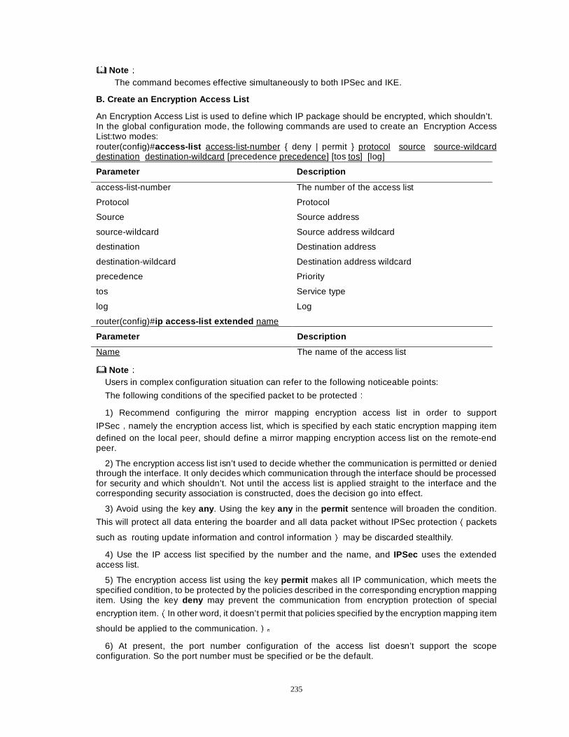
235
NoteÛÛ The command becomes effective simultaneously to both IPSec and IKE.
B. Create an Encryption Access List
An Encryption Access List is used to define which IP package should be encrypted, which shouldn’t. In the global configuration mode, the following commands are used to create an Encryption Access List:two modes: router(config)#access-list access-list-number { deny | permit } protocol source source-wildcard destination destination-wildcard [precedence precedence] [tos tos] [log]
Parameter Description
access-list-number The number of the access list
Protocol Protocol
Source Source address
source-wildcard Source address wildcard
destination Destination address
destination-wildcard Destination address wildcard
precedence Priority
tos Service type
log Log
router(config)#ip access-list extended name
Parameter Description
Name The name of the access list
NoteÛÛ Users in complex configuration situation can refer to the following noticeable points:
The following conditions of the specified packet to be protectedÛ
1) Recommend configuring the mirror mapping encryption access list in order to support
IPSecÍnamely the encryption access list, which is specified by each static encryption mapping item defined on the local peer, should define a mirror mapping encryption access list on the remote-end peer.
2) The encryption access list isn’t used to decide whether the communication is permitted or denied through the interface. It only decides which communication through the interface should be processed for security and which shouldn’t. Not until the access list is applied straight to the interface and the corresponding security association is constructed, does the decision go into effect.
3) Avoid using the key any . Using the key any in the permit sentence will broaden the condition.
This will protect all data entering the boarder and all data packet without IPSec protectionÉpackets
such as routing update information and control informationÊ may be discarded stealthily.
4) Use the IP access list specified by the number and the name, and IPSec uses the extended access list.
5) The encryption access list using the key permit makes all IP communication, which meets the specified condition, to be protected by the policies described in the corresponding encryption mapping item. Using the key deny may prevent the communication from encryption protection of special
encryption item.ÉIn other word, it doesn’t permit that policies specified by the encryption mapping item
should be applied to the communication.Ê>
6) At present, the port number configuration of the access list doesn’t support the scope configuration. So the port number must be specified or be the default.
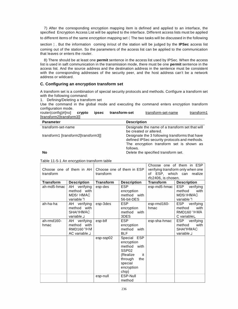
236
7) After the corresponding encryption mapping item is defined and applied to an interface, the specified Encryption Access List will be applied to the interface. Different access lists must be applied
to different items of the same encryption mapping setÉThe two tasks will be discussed in the following
sectionÊ. But the information coming in/out of the station will be judged by the IPSec access list coming out of the station. So the parameters of the access list can be applied to the communication that leaves or enters the router.
8) There should be at least one permit sentence in the access list used by IPSec. When the access list is used in saft communication in the transmission mode, there must be one permit sentence in the access list. And the source address and the destination address in the sentence must be consistent with the corresponding addresses of the security peer, and the host address can’t be a network address or wildcard.
C. Configuring an encryption transform set
A transform set is a combination of special security protocols and methods. Configure a transform set with the following command: 1. Defining/Deleting a transform set Use the command in the global mode and executing the command enters encryption transform configuration mode. router(config)#[no] crypto ipsec transform-set transform-set-name transform1 [transform2[transform3]]
Parameter Description transform-set-name Designate the name of a transform set that will
be created or altered. transform1 [transform2[transform3]] Designate the 3 following transforms that have
defined IPSec security protocols and methods. The encryption transform set is shown as follows.
No Delete the specified transform set. Table 11-5-1 An encryption transform table
Choose one of them in AH transform
Choose one of them in ESP transform
Choose one of them in ESP verifying transform only when one of ESP, which can realize rfc2406, is chosen.
Transform Description Transform Description Transform Description ah-md5-hmac AH verifying
method with MD5�+0$&variable�
esp-des ESP encryption method with 56-bit-DES
esp-md5-hmac ESP verifying method with MD5�+0$&variable�
ah-ha-ha AH verifying method with SHA�+0$&variable�
esp-3des ESP encryption method with 3DES
esp-rmd160-hmac
ESP verifying method with RMD160�+0$C variable�
ah-rmd160-hmac
AH verifying method with RMD160�+0AC variable�
esp-blf ESP encryption method with BLF
esp-sha-hmac ESP verifying method with SHA�+0$&variable�
esp-ssp02 Special ESP encryption method with SSP02 (Realize it through the special encryption chip)
esp-null ESP-Null method
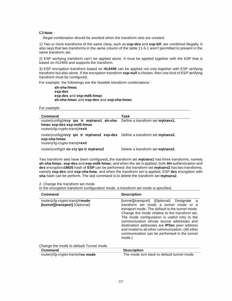
237
NoteÛÛ Illegal combination should be avoided when the transform sets are created.
1) Two or more transforms of the same class, such as esp-des and esp-blf , are combined illegally. It also says that two transforms in the same column of the table 11-5-1 aren’t permitted to present in the same transform set.
2) ESP verifying transform can’t be applied alone. It must be applied together with the ESP that is based on rfc2406 and supports the transform.
3) ESP encryption transform based on rfc2406 can be applied not only together with ESP verifying transform but also alone. If the encryption transform esp-null is chosen, then one kind of ESP verifying transform must be configured.
For example: the followings are the feasible transform combinationsÛ ah-sha-hmac esp-des esp-des and esp-md5-hmac ah-sha-hmac and esp-des and esp-sha-hmac
For example:
Command Task router(config)#cry ips tr mytrans1 ah-sha-hmac esp-des esp-md5-hmac
Define a transform set mytrans1.
router(cfg-crypto-trans)#exit
router(config)#cry ips tr mytrans2 esp-des esp-sha-hmac
Define a transform set mytrans2.
router(cfg-crypto-trans)#exit
router(config)# no cry ips tr mytrans2 Delete a transform set mytrans2.
Two transform sets have been configured�the transform set mytrans1 has three transforms, namely ah-sha-hmac , esp-des and esp-md5-hmac ; and when the set is applied, both AH authentication and des encryption&MD5 hash of ESP can be performed; the transform set mytrans2 has two transforms, namely esp-des and esp-sha-hma , and when the transform set is applied, ESP des encryption with sha hash can be perform. The last command is to delete the transform set mytrans2 . 2. Change the transform set mode In the encryption transform configuration mode, a transform set mode is specified.
Command Description
router(cfg-crypto-trans)#mode [tunnel][transport] (Optional)
[tunnel][transport] (Optional) Designate a transform set mode a tunnel mode or a transport mode. The default is the tunnel mode. Change the mode relative to the transform set. The mode configuration is useful only to the communication whose source addresses and destination addresses are IPSec peer address and invalid to all other communication. (All other communication can be performed in the tunnel mode.)
Change the mode to default Tunnel mode
Command Description router(cfg-crypto-trans)#no mode The mode turn back to default tunnel mode.
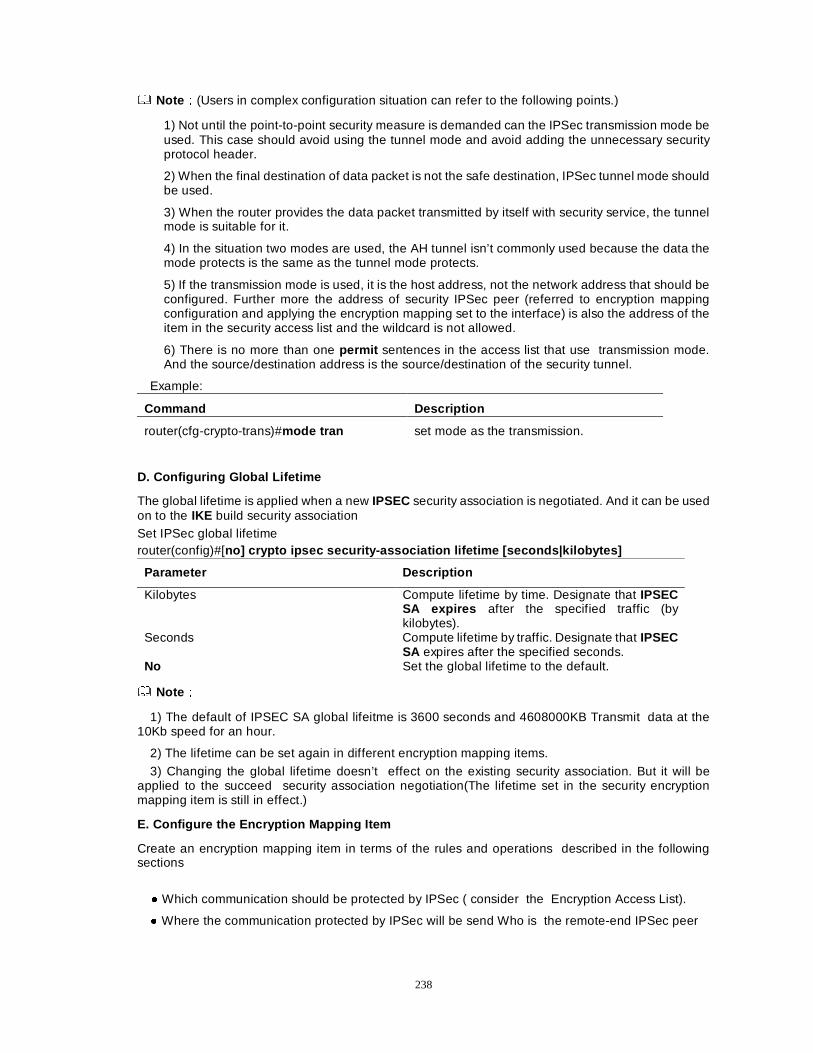
238
NoteÛÛ(Users in complex configuration situation can refer to the following points.)
1) Not until the point-to-point security measure is demanded can the IPSec transmission mode be used. This case should avoid using the tunnel mode and avoid adding the unnecessary security protocol header.
2) When the final destination of data packet is not the safe destination, IPSec tunnel mode should be used.
3) When the router provides the data packet transmitted by itself with security service, the tunnel mode is suitable for it.
4) In the situation two modes are used, the AH tunnel isn’t commonly used because the data the mode protects is the same as the tunnel mode protects.
5) If the transmission mode is used, it is the host address, not the network address that should be configured. Further more the address of security IPSec peer (referred to encryption mapping configuration and applying the encryption mapping set to the interface) is also the address of the item in the security access list and the wildcard is not allowed.
6) There is no more than one permit sentences in the access list that use transmission mode. And the source/destination address is the source/destination of the security tunnel.
Example:
Command Description
router(cfg-crypto-trans)#mode tran set mode as the transmission.
D. Configuring Global Lifetime
The global lifetime is applied when a new IPSEC security association is negotiated. And it can be used on to the IKE build security association Set IPSec global lifetime router(config)#[no] crypto ipsec security-association lifetime [seconds|kilobytes]
Parameter Description
Kilobytes Compute lifetime by time. Designate that IPSEC SA expires after the specified traffic (by kilobytes).
Seconds Compute lifetime by traffic. Designate that IPSEC SA expires after the specified seconds.
No Set the global lifetime to the default.
NoteÛÛ
1) The default of IPSEC SA global lifeitme is 3600 seconds and 4608000KB Transmit data at the 10Kb speed for an hour.
2) The lifetime can be set again in different encryption mapping items.
3) Changing the global lifetime doesn’t effect on the existing security association. But it will be applied to the succeed security association negotiation(The lifetime set in the security encryption mapping item is still in effect.)
E. Configure the Encryption Mapping Item
Create an encryption mapping item in terms of the rules and operations described in the following sections
� Which communication should be protected by IPSec ( consider the Encryption Access List).
� Where the communication protected by IPSec will be send Who is the remote-end IPSec peer
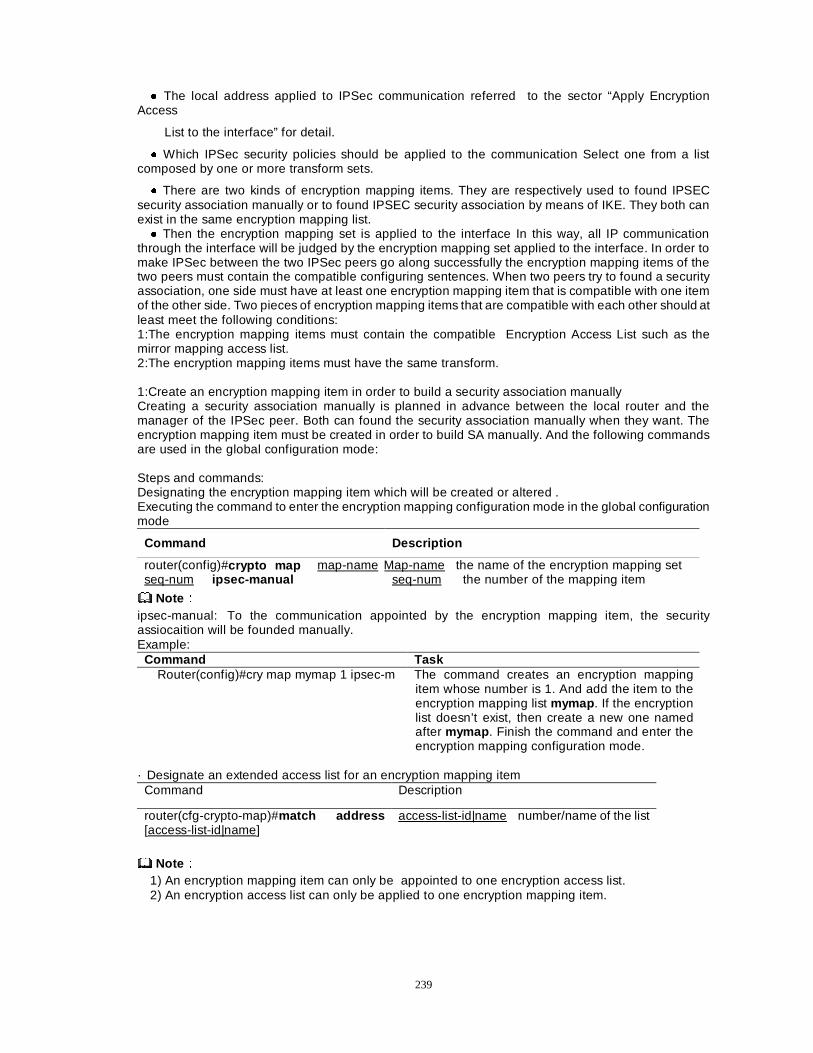
239
� The local address applied to IPSec communication referred to the sector “Apply Encryption Access
List to the interface” for detail.
� Which IPSec security policies should be applied to the communication Select one from a list composed by one or more transform sets.
� There are two kinds of encryption mapping items. They are respectively used to found IPSEC security association manually or to found IPSEC security association by means of IKE. They both can exist in the same encryption mapping list. � Then the encryption mapping set is applied to the interface In this way, all IP communication
through the interface will be judged by the encryption mapping set applied to the interface. In order to make IPSec between the two IPSec peers go along successfully the encryption mapping items of the two peers must contain the compatible configuring sentences. When two peers try to found a security association, one side must have at least one encryption mapping item that is compatible with one item of the other side. Two pieces of encryption mapping items that are compatible with each other should at least meet the following conditions: 1:The encryption mapping items must contain the compatible Encryption Access List such as the mirror mapping access list. 2:The encryption mapping items must have the same transform. 1:Create an encryption mapping item in order to build a security association manually Creating a security association manually is planned in advance between the local router and the manager of the IPSec peer. Both can found the security association manually when they want. The encryption mapping item must be created in order to build SA manually. And the following commands are used in the global configuration mode: Steps and commands: Designating the encryption mapping item which will be created or altered . Executing the command to enter the encryption mapping configuration mode in the global configuration mode
Command Description
router(config)#crypto map map-name seq-num ipsec-manual
Map-name the name of the encryption mapping set seq-num the number of the mapping item
NoteÛÛ ipsec-manual: To the communication appointed by the encryption mapping item, the security assiocaition will be founded manually. Example:
Command Task Router(config)#cry map mymap 1 ipsec-m The command creates an encryption mapping
item whose number is 1. And add the item to the encryption mapping list mymap . If the encryption list doesn’t exist, then create a new one named after mymap . Finish the command and enter the encryption mapping configuration mode.
· Designate an extended access list for an encryption mapping item
Command Description
router(cfg-crypto-map)#match address [access-list-id|name]
access-list-id|name number/name of the list
NoteÛÛ 1) An encryption mapping item can only be appointed to one encryption access list. 2) An encryption access list can only be applied to one encryption mapping item.
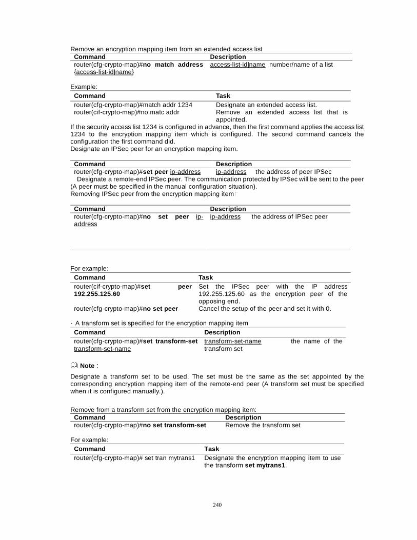
240
Remove an encryption mapping item from an extended access list Command Description router(cfg-crypto-map)#no match address {access-list-id|name}
access-list-id|name number/name of a list
Example:
Command Task router(cfg-crypto-map)#match addr 1234 Designate an extended access list. router(cif-crypto-map)#no matc addr Remove an extended access list that is
appointed. If the security access list 1234 is configured in advance, then the first command applies the access list 1234 to the encryption mapping item which is configured. The second command cancels the configuration the first command did. Designate an IPSec peer for an encryption mapping item.
Command Description router(cfg-crypto-map)#set peer ip-address ip-address the address of peer IPSec Designate a remote-end IPSec peer. The communication protected by IPSec will be sent to the peer
(A peer must be specified in the manual configuration situation). Removing IPSec peer from the encryption mapping item�
Command Description router(cfg-crypto-map)#no set peer ip-address
ip-address the address of IPSec peer
For example:
Command Task router(cif-crypto-map)#set peer 192.255.125.60
Set the IPSec peer with the IP address 192.255.125.60 as the encryption peer of the opposing end.
router(cfg-crypto-map)#no set peer Cancel the setup of the peer and set it with 0. · A transform set is specified for the encryption mapping item
Command Description router(cfg-crypto-map)#set transform-set transform-set-name
transform-set-name the name of the transform set
NoteÛÛ
Designate a transform set to be used. The set must be the same as the set appointed by the corresponding encryption mapping item of the remote-end peer (A transform set must be specified when it is configured manually.).
Remove from a transform set from the encryption mapping item: Command Description router(cfg-crypto-map)#no set transform-set Remove the transform set
For example:
Command Task router(cfg-crypto-map)# set tran mytrans1 Designate the encryption mapping item to use
the transform set mytrans1 .
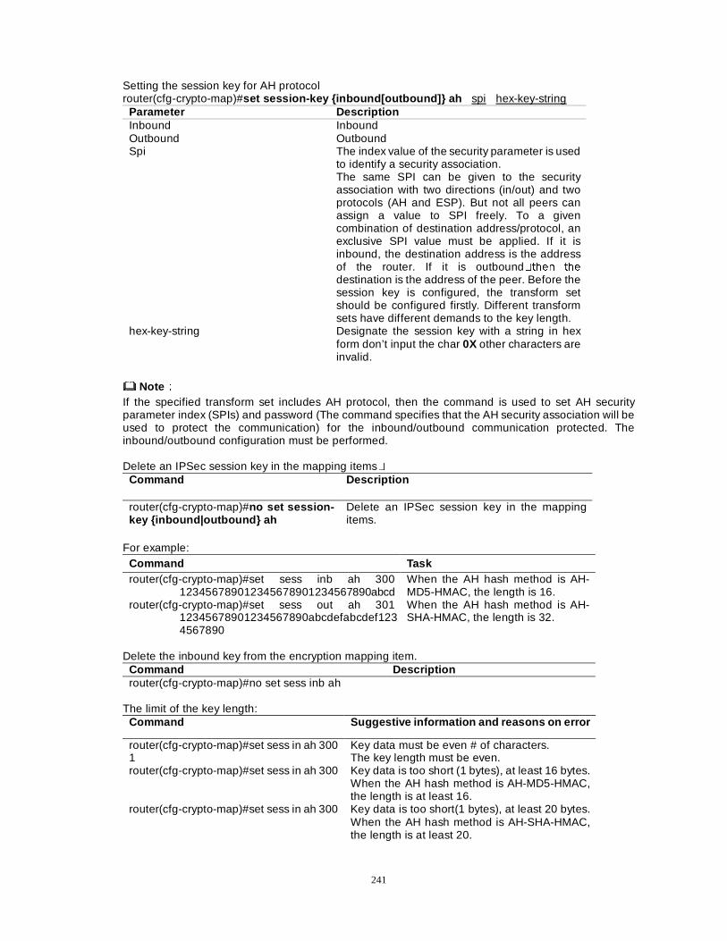
241
Setting the session key for AH protocol router(cfg-crypto-map)#set session-key {inbound[outbound]} ah spi hex-key-string
Parameter Description Inbound Inbound Outbound Outbound Spi The index value of the security parameter is used
to identify a security association. The same SPI can be given to the security association with two directions (in/out) and two protocols (AH and ESP). But not all peers can assign a value to SPI freely. To a given combination of destination address/protocol, an exclusive SPI value must be applied. If it is inbound, the destination address is the address of the router. If it is outbound�WKHQ WKH
destination is the address of the peer. Before the session key is configured, the transform set should be configured firstly. Different transform sets have different demands to the key length.
hex-key-string Designate the session key with a string in hex form don’t input the char 0X other characters are invalid.
NoteÛÛ If the specified transform set includes AH protocol, then the command is used to set AH security parameter index (SPIs) and password (The command specifies that the AH security association will be used to protect the communication) for the inbound/outbound communication protected. The inbound/outbound configuration must be performed. Delete an IPSec session key in the mapping items�
Command Description
router(cfg-crypto-map)#no set session-key {inbound|outbound} ah
Delete an IPSec session key in the mapping items.
For example:
Command Task router(cfg-crypto-map)#set sess inb ah 300
123456789012345678901234567890abcd When the AH hash method is AH-MD5-HMAC, the length is 16.
router(cfg-crypto-map)#set sess out ah 301 12345678901234567890abcdefabcdef1234567890
When the AH hash method is AH-SHA-HMAC, the length is 32.
Delete the inbound key from the encryption mapping item.
Command Description router(cfg-crypto-map)#no set sess inb ah
The limit of the key length:
Command Suggestive information and reasons on error
router(cfg-crypto-map)#set sess in ah 300 1
Key data must be even # of characters. The key length must be even.
router(cfg-crypto-map)#set sess in ah 300 Key data is too short (1 bytes), at least 16 bytes. When the AH hash method is AH-MD5-HMAC, the length is at least 16.
router(cfg-crypto-map)#set sess in ah 300 Key data is too short(1 bytes), at least 20 bytes. When the AH hash method is AH-SHA-HMAC, the length is at least 20.
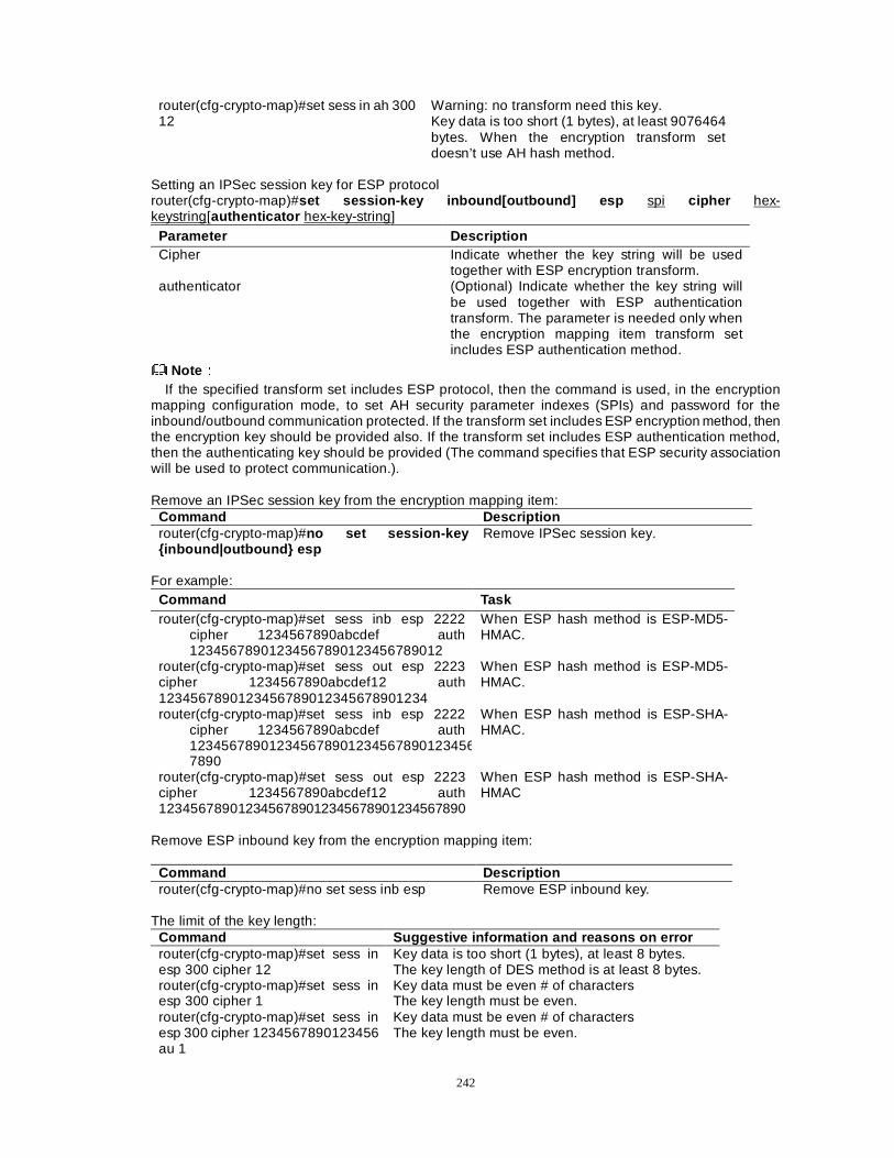
242
router(cfg-crypto-map)#set sess in ah 300 12
Warning: no transform need this key. Key data is too short (1 bytes), at least 9076464 bytes. When the encryption transform set doesn’t use AH hash method.
Setting an IPSec session key for ESP protocol router(cfg-crypto-map)#set session-key inbound[outbound] esp spi cipher hex-keystring[authenticator hex-key-string]
Parameter Description Cipher Indicate whether the key string will be used
together with ESP encryption transform. authenticator (Optional) Indicate whether the key string will
be used together with ESP authentication transform. The parameter is needed only when the encryption mapping item transform set includes ESP authentication method.
NoteÛÛ If the specified transform set includes ESP protocol, then the command is used, in the encryption
mapping configuration mode, to set AH security parameter indexes (SPIs) and password for the inbound/outbound communication protected. If the transform set includes ESP encryption method, then the encryption key should be provided also. If the transform set includes ESP authentication method, then the authenticating key should be provided (The command specifies that ESP security association will be used to protect communication.).
Remove an IPSec session key from the encryption mapping item:
Command Description router(cfg-crypto-map)#no set session-key {inbound|outbound} esp
Remove IPSec session key.
For example:
Command Task router(cfg-crypto-map)#set sess inb esp 2222
cipher 1234567890abcdef auth 12345678901234567890123456789012
When ESP hash method is ESP-MD5-HMAC.
router(cfg-crypto-map)#set sess out esp 2223 cipher 1234567890abcdef12 auth 1234567890123456789012345678901234
When ESP hash method is ESP-MD5-HMAC.
router(cfg-crypto-map)#set sess inb esp 2222 cipher 1234567890abcdef auth 1234567890123456789012345678901234567890
When ESP hash method is ESP-SHA-HMAC.
router(cfg-crypto-map)#set sess out esp 2223 cipher 1234567890abcdef12 auth 1234567890123456789012345678901234567890
When ESP hash method is ESP-SHA-HMAC
Remove ESP inbound key from the encryption mapping item:
Command Description router(cfg-crypto-map)#no set sess inb esp Remove ESP inbound key.
The limit of the key length:
Command Suggestive information and reasons on error router(cfg-crypto-map)#set sess in esp 300 cipher 12
Key data is too short (1 bytes), at least 8 bytes. The key length of DES method is at least 8 bytes.
router(cfg-crypto-map)#set sess in esp 300 cipher 1
Key data must be even # of characters The key length must be even.
router(cfg-crypto-map)#set sess in esp 300 cipher 1234567890123456 au 1
Key data must be even # of characters The key length must be even.
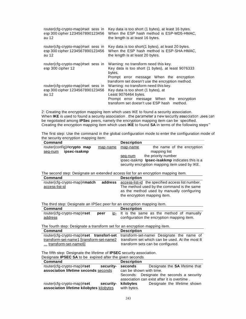
243
router(cfg-crypto-map)#set sess in esp 300 cipher 1234567890123456 au 12
Key data is too short (1 bytes), at least 16 bytes. When the ESP hash method is ESP-MD5-HMAC, the length is at least 16 bytes.
router(cfg-crypto-map)#set sess in esp 300 cipher 1234567890123456 au 12
Key data is too short(1 bytes), at least 20 bytes. When the ESP hash method is ESP-SHA-HMAC, the length is at least 20 bytes.
router(cfg-crypto-map)#set sess in esp 300 cipher 12
Warning: no transform need this key. Key data is too short (1 bytes), at least 9076333 bytes. Prompt error message When the encryption transform set doesn’t use the encryption method.
router(cfg-crypto-map)#set sess in esp 300 cipher 1234567890123456 au 12
Warning: no transform need this key. Key data is too short (1 bytes), at Least 9076464 bytes. Prompt error message When the encryption transform set doesn’t use ESP hash method.
2: Creating the encryption mapping item which uses IKE to found a security association. When IKE is used to found a security association��WKH SDUDPHWHU D QHZ VHFXULW\ DVVRFLDWLRQ XVHV FDQ
be negotiated among IPSec peers, namely the encryption mapping item can be specified. Creating the encryption mapping item which uses IKE to found SA in terms of the following steps� The first step: Use the command in the global configuration mode to enter the configuration mode of the security encryption mapping item:
Command Description router(config)#crypto map map-name seq-num ipsec-isakmp
map-name the name of the encryption mapping list
seq-num the priority number ipsec-isakmp Ipsec-isakkmp indicates this is a security encryption mapping item used by IKE.
The second step: Designate an extended access list for an encryption mapping item.
Command Description router(cfg-crypto-map)#match address access-list-id
access-list-id the specified access list number. The method used by the command is the same as the method used by manually configuring the encryption mapping item.
The third step: Designate an IPSec peer for an encryption mapping item.
Command Description router(cfg-crypto-map)#set peer ip-address
It is the same as the method of manually configuration the encryption mapping item.
The fourth step: Designate a transform set for an encryption mapping item.
Command Description router(cfg-crypto-map)#set transforl-set transform-set-name1 [transform-set-name2 … transform-set-name6]
transform-set-namei Designate the name of transform set which can be used. At the most 8 transform sets can be configured.
The fifth step: Designate the lifetime of IPSEC security association. Designate IPSEC SA to be expired after the given seconds
Command Description router(cfg-crypto-map)#set security-association lifetime seconds seconds
seconds Designate the SA lifetime that can be shown with time. Seconds: Designate the seconds a security association can exist after it is overtime .
router(cfg-crypto-map)#set security-association lifetime kilobytes kilobytes
kilobytes Designate the lifetime shown with bytes.
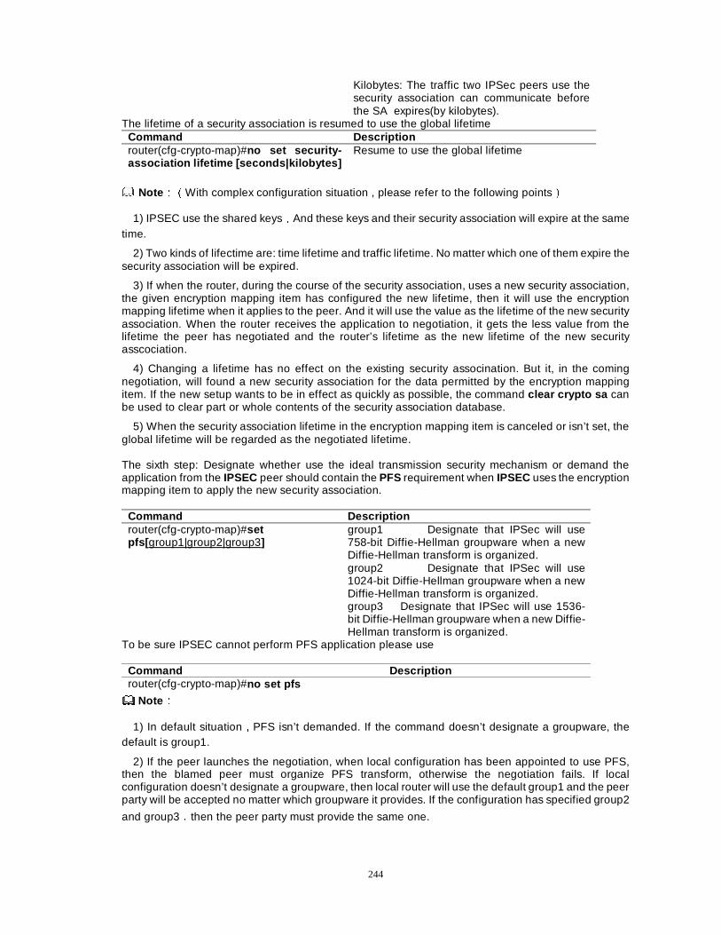
244
Kilobytes: The traffic two IPSec peers use the security association can communicate before the SA expires(by kilobytes).
The lifetime of a security association is resumed to use the global lifetime Command Description router(cfg-crypto-map)#no set security-association lifetime [seconds|kilobytes]
Resume to use the global lifetime
NoteÛÛÉWith complex configuration situation , please refer to the following pointsÊ
1) IPSEC use the shared keysÍAnd these keys and their security association will expire at the same time.
2) Two kinds of lifectime are: time lifetime and traffic lifetime. No matter which one of them expire the security association will be expired.
3) If when the router, during the course of the security association, uses a new security association, the given encryption mapping item has configured the new lifetime, then it will use the encryption mapping lifetime when it applies to the peer. And it will use the value as the lifetime of the new security association. When the router receives the application to negotiation, it gets the less value from the lifetime the peer has negotiated and the router’s lifetime as the new lifetime of the new security asscociation.
4) Changing a lifetime has no effect on the existing security assocination. But it, in the coming negotiation, will found a new security association for the data permitted by the encryption mapping item. If the new setup wants to be in effect as quickly as possible, the command clear crypto sa can be used to clear part or whole contents of the security association database.
5) When the security association lifetime in the encryption mapping item is canceled or isn’t set, the global lifetime will be regarded as the negotiated lifetime. The sixth step: Designate whether use the ideal transmission security mechanism or demand the application from the IPSEC peer should contain the PFS requirement when IPSEC uses the encryption mapping item to apply the new security association.
Command Description router(cfg-crypto-map)#set pfs[ group1|group2|group3]
group1 Designate that IPSec will use 758-bit Diffie-Hellman groupware when a new Diffie-Hellman transform is organized. group2 Designate that IPSec will use 1024-bit Diffie-Hellman groupware when a new Diffie-Hellman transform is organized. group3 Designate that IPSec will use 1536-bit Diffie-Hellman groupware when a new Diffie-Hellman transform is organized.
To be sure IPSEC cannot perform PFS application please use
Command Description router(cfg-crypto-map)#no set pfs
NoteÛÛ
1) In default situationÍPFS isn’t demanded. If the command doesn’t designate a groupware, the default is group1.
2) If the peer launches the negotiation, when local configuration has been appointed to use PFS, then the blamed peer must organize PFS transform, otherwise the negotiation fails. If local configuration doesn’t designate a groupware, then local router will use the default group1 and the peer party will be accepted no matter which groupware it provides. If the configuration has specified group2
and group3Íthen the peer party must provide the same one.
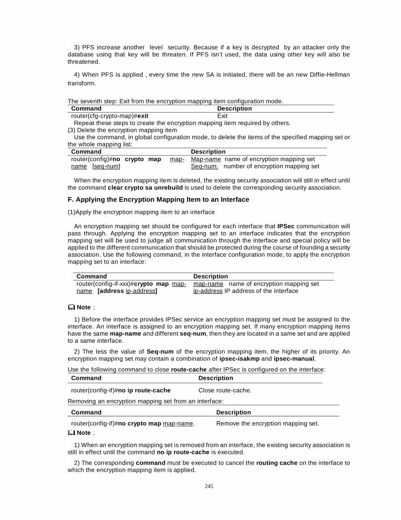
245
3) PFS increase another level security. Because if a key is decrypted by an attacker only the database using that key will be threaten. If PFS isn’t used, the data using other key will also be threatened.
4) When PFS is appliedÍevery time the new SA is initiated, there will be an new Diffie-Hellman transform.
The seventh step: Exit from the encryption mapping item configuration mode.
Command Description router(cfg-crypto-map)#exit Exit Repeat these steps to create the encryption mapping item required by others.
(3) Delete the encryption mapping item Use the command, in global configuration mode, to delete the items of the specified mapping set or
the whole mapping list: Command Description router(config)#no crypto map map-name [seq-num]
Map-name name of encryption mapping set Seq-num: number of encryption mapping set
When the encryption mapping item is deleted, the existing security association will still in effect until
the command clear crypto sa unrebuild is used to delete the corresponding security association.
F. Applying the Encryption Mapping Item to an Interface
(1)Apply the encryption mapping item to an interface
An encryption mapping set should be configured for each interface that IPSec communication will pass through. Applying the encryption mapping set to an interface indicates that the encryption mapping set will be used to judge all communication through the interface and special policy will be applied to the different communication that should be protected during the course of founding a security association. Use the following command, in the interface configuration mode, to apply the encryption mapping set to an interface:
Command Description router(config-if-xxx)#crypto map map-name [address ip-address]
map-name name of encryption mapping set ip-address IP address of the interface
NoteÛÛ
1) Before the interface provides IPSec service an encryption mapping set must be assigned to the interface. An interface is assigned to an encryption mapping set. If many encryption mapping items have the same map-name and different seq-num , then they are located in a same set and are applied to a same interface.
2) The less the value of Seq-num of the encryption mapping item, the higher of its priority. An encryption mapping set may contain a combination of ipsec-isakmp and ipsec-manual .
Use the following command to close route-cache after IPSec is configured on the interface: Command Description
router(config-if)#no ip route-cache Close route-cache.
Removing an encryption mapping set from an interface:
Command Description
router(config-if)#no crypto map map-name. Remove the encryption mapping set.
NoteÛÛ
1) When an encryption mapping set is removed from an interface, the existing security association is still in effect until the command no ip route-cache is executed.
2) The corresponding command must be executed to cancel the routing cache on the interface to which the encryption mapping item is applied.
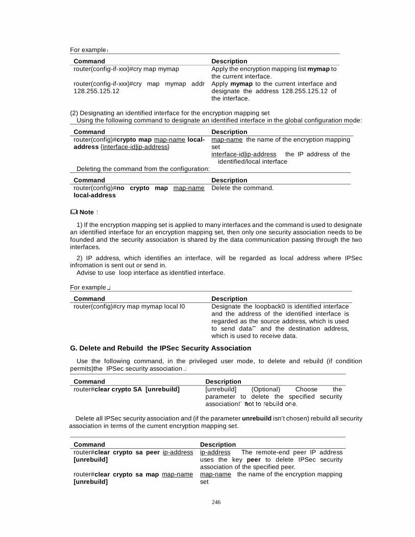
246
For exampleÖ
Command Description router(config-if-xxx)#cry map mymap Apply the encryption mapping list mymap to
the current interface. router(config-if-xxx)#cry map mymap addr 128.255.125.12
Apply mymap to the current interface and designate the address 128.255.125.12 of the interface.
(2) Designating an identified interface for the encryption mapping set
Using the following command to designate an identified interface in the global configuration mode:
Command Description router(config)#crypto map map-name local-address {interface-id|ip-address}
map-name the name of the encryption mapping set interface-id|ip-address the IP address of the
identified/local interface Deleting the command from the configuration:
Command Description router(config)#no crypto map map-name local-address
Delete the command.
NoteÛÛ
1) If the encryption mapping set is applied to many interfaces and the command is used to designate an identified interface for an encryption mapping set, then only one security association needs to be founded and the security association is shared by the data communication passing through the two interfaces.
2) IP address, which identifies an interface, will be regarded as local address where IPSec infromation is sent out or send in.
Advise to use loop interface as identified interface. For example�
Command Description router(config)#cry map mymap local l0 Designate the loopback0 is identified interface
and the address of the identified interface is regarded as the source address, which is used to send data� and the destination address, which is used to receive data.
G. Delete and Rebuild the IPSec Security Association
Use the following command, in the privileged user mode, to delete and rebuild (if condition permits)the IPSec security association�
Command Description router#clear crypto SA [unrebuild] [unrebuild] (Optional) Choose the
parameter to delete the specified security association��QRW WR UHEXLOG RQH�
Delete all IPSec security association and (if the parameter unrebuild isn’t chosen) rebuild all security
association in terms of the current encryption mapping set.
Command Description router#clear crypto sa peer ip-address [unrebuild]
ip-address The remote-end peer IP address uses the key peer to delete IPSec security association of the specified peer.
router#clear crypto sa map map-name [unrebuild]
map-name the name of the encryption mapping set
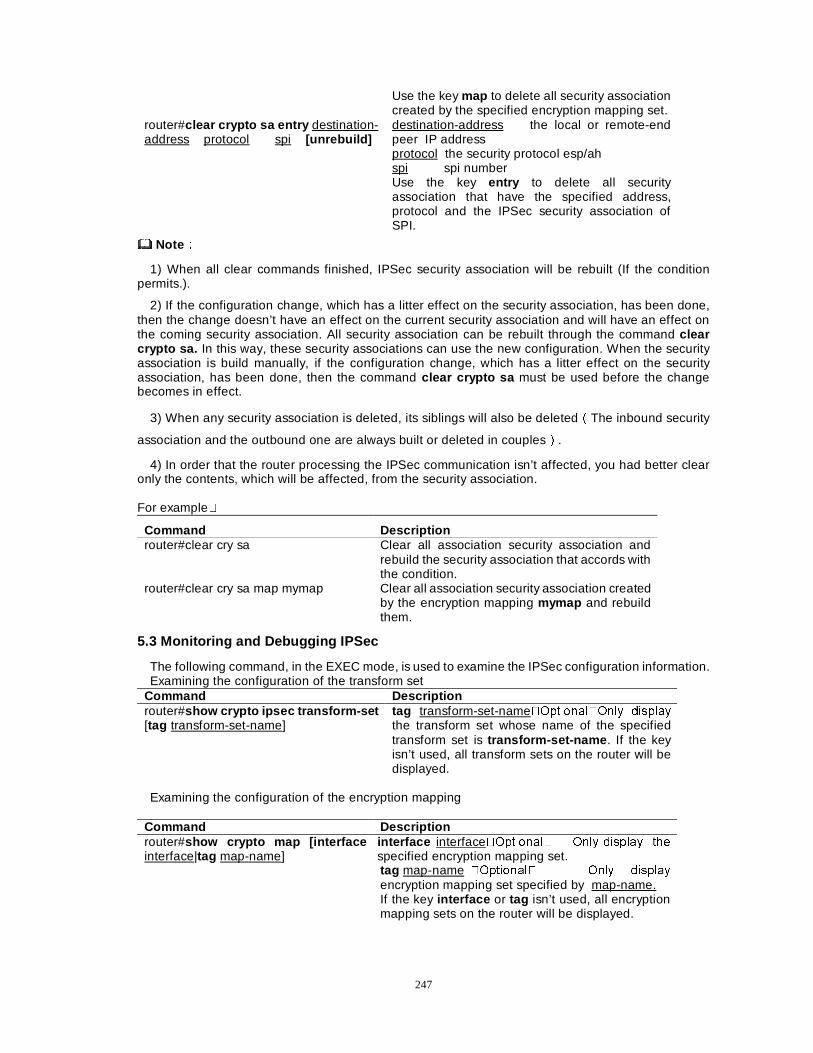
247
Use the key map to delete all security association created by the specified encryption mapping set.
router#clear crypto sa entry destination-address protocol spi [unrebuild]
destination-address the local or remote-end peer IP address protocol the security protocol esp/ah spi spi number Use the key entry to delete all security association that have the specified address, protocol and the IPSec security association of SPI.
NoteÛÛ
1) When all clear commands finished, IPSec security association will be rebuilt (If the condition permits.).
2) If the configuration change, which has a litter effect on the security association, has been done, then the change doesn’t have an effect on the current security association and will have an effect on the coming security association. All security association can be rebuilt through the command clear crypto sa. In this way, these security associations can use the new configuration. When the security association is build manually, if the configuration change, which has a litter effect on the security association, has been done, then the command clear crypto sa must be used before the change becomes in effect.
3) When any security association is deleted, its siblings will also be deletedÉThe inbound security
association and the outbound one are always built or deleted in couplesÊ.
4) In order that the router processing the IPSec communication isn’t affected, you had better clear only the contents, which will be affected, from the security association. For example�
Command Description router#clear cry sa Clear all association security association and
rebuild the security association that accords with the condition.
router#clear cry sa map mymap Clear all association security association created by the encryption mapping mymap and rebuild them.
5.3 Monitoring and Debugging IPSec
The following command, in the EXEC mode, is used to examine the IPSec configuration information. Examining the configuration of the transform set
Command Description router#show crypto ipsec transform-set [tag transform-set-name]
tag transform-set-name�2SWLRQDO�2QO\ GLVSOD\
the transform set whose name of the specified transform set is transform-set-name . If the key isn’t used, all transform sets on the router will be displayed.
Examining the configuration of the encryption mapping
Command Description router#show crypto map [interface interface|tag map-name]
interface interface�2SWLRQDO� 2QO\ GLVSOD\ WKH
specified encryption mapping set. tag map-name �2SWLRQDO� 2QO\ GLVSOD\
encryption mapping set specified by map-name. If the key interface or tag isn’t used, all encryption mapping sets on the router will be displayed.
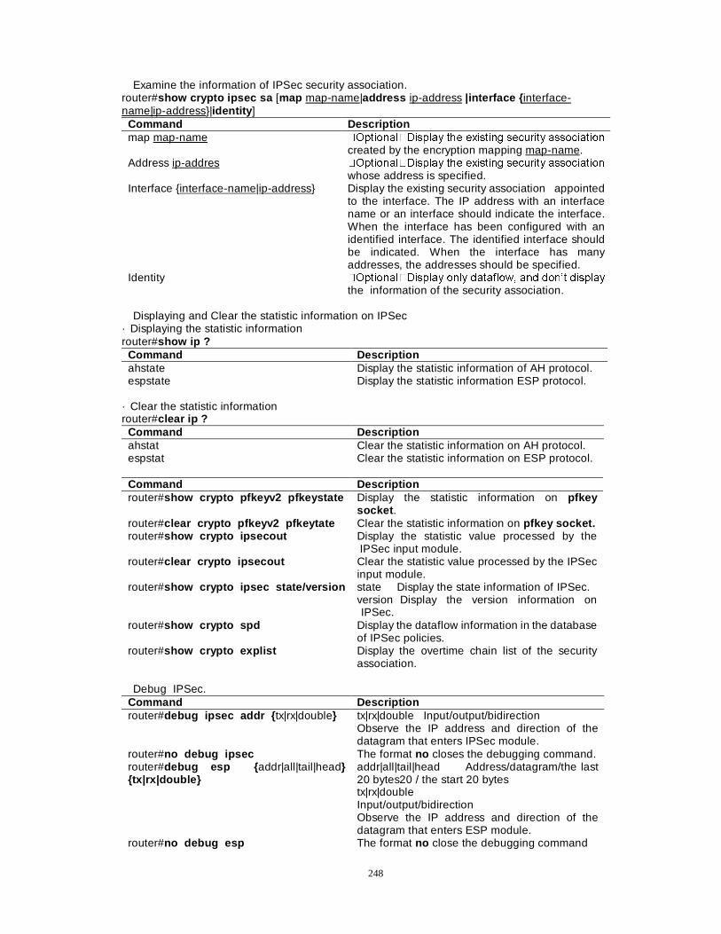
248
Examine the information of IPSec security association. router#show crypto ipsec sa [map map-name|address ip-address |interface { interface- name|ip-address}|identity ]
Command Description map map-name �2SWLRQDO�'LVSOD\ WKH H[LVWLQJ VHFXULW\ DVVRFLDWLRQ
created by the encryption mapping map-name. Address ip-addres �2SWLRQDO�'LVSOD\ WKH H[LVWLQJ VHFXULW\ DVVRFLDWLRQ
whose address is specified. Interface {interface-name|ip-address} Display the existing security association appointed
to the interface. The IP address with an interface name or an interface should indicate the interface. When the interface has been configured with an identified interface. The identified interface should be indicated. When the interface has many addresses, the addresses should be specified.
Identity �2SWLRQDO�'LVSOD\ RQO\ GDWDIORZ� DQG GRQ¶W GLVSOD\
the information of the security association.
Displaying and Clear the statistic information on IPSec · Displaying the statistic information router#show ip ?
Command Description ahstate Display the statistic information of AH protocol. espstate Display the statistic information ESP protocol.
· Clear the statistic information router#clear ip ?
Command Description ahstat Clear the statistic information on AH protocol. espstat Clear the statistic information on ESP protocol.
Command Description router#show crypto pfkeyv2 pfkeystate Display the statistic information on pfkey
socket . router#clear crypto pfkeyv2 pfkeytate Clear the statistic information on pfkey socket. router#show crypto ipsecout Display the statistic value processed by the
IPSec input module. router#clear crypto ipsecout Clear the statistic value processed by the IPSec
input module. router#show crypto ipsec state/version state Display the state information of IPSec.
version Display the version information on IPSec.
router#show crypto spd Display the dataflow information in the database of IPSec policies.
router#show crypto explist Display the overtime chain list of the security association.
Debug IPSec.
Command Description router#debug ipsec addr { tx|rx|double} tx|rx|double Input/output/bidirection
Observe the IP address and direction of the datagram that enters IPSec module.
router#no debug ipsec The format no closes the debugging command. router#debug esp { addr|all|tail|head} {tx|rx|double}
addr|all|tail|head Address/datagram/the last 20 bytes20 / the start 20 bytes tx|rx|double Input/output/bidirection Observe the IP address and direction of the datagram that enters ESP module.
router#no debug esp The format no close the debugging command
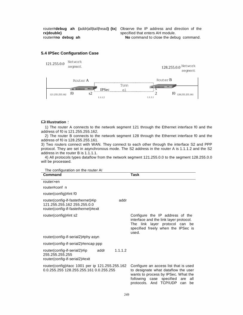
249
router#debug ah { addr|all|tail|head} {tx| rx|double}
Observe the IP address and direction of the specified that enters AH module.
router#no debug ah No command to close the debug command.
5.4 IPSec Configuration Case
Router A
f0
Router B
s2 f0
IPSecTunnel
121.255.255.1621.1.1.2 1.1.1.1
128.255.255.161
121.255.0.0 Networksegment 128.255.0.0Network
segment
s2
Illustration ÛÛ
1) The router A connects to the network segment 121 through the Ethernet interface f0 and the address of f0 is 121.255.255.162.
2) The router B connects to the network segment 128 through the Ethernet interface f0 and the address of f0 is 128.255.255.161. 3) Two routers connect with WAN. They connect to each other through the interface S2 and PPP protocol. They are set in asynchronous mode. The S2 address in the router A is 1.1.1.2 and the S2 address in the router B is 1.1.1.1.
4) All protocols types dataflow from the network segment 121.255.0.0 to the segment 128.255.0.0 will be processed.
The configuration on the router A�
Command Task
router>en
router#conf n
router(config)#int f0
router(config-if-fastethernet)#ip addr 121.255.255.162 255.255.0.0
router(config-if-fastethernet)#exit
router(config)#int s2 Configure the IP address of the interface and the link layer protocol. The link layer protocol can be specified freely when the IPSec is used.
router(config-if-serial2)#phy asyn
router(config-if-serial2)#encap ppp
router(config-if-serial2)#ip addr 1.1.1.2 255.255.255.255
router(config-if-serial2)#exit
router(config)#acc 1001 per ip 121.255.255.162 0.0.255.255 128.255.255.161 0.0.255.255
Configure an access list that is used to designate what dataflow the user wants to process by IPSec. What the following case specified are all protocols. And TCP/UDP can be
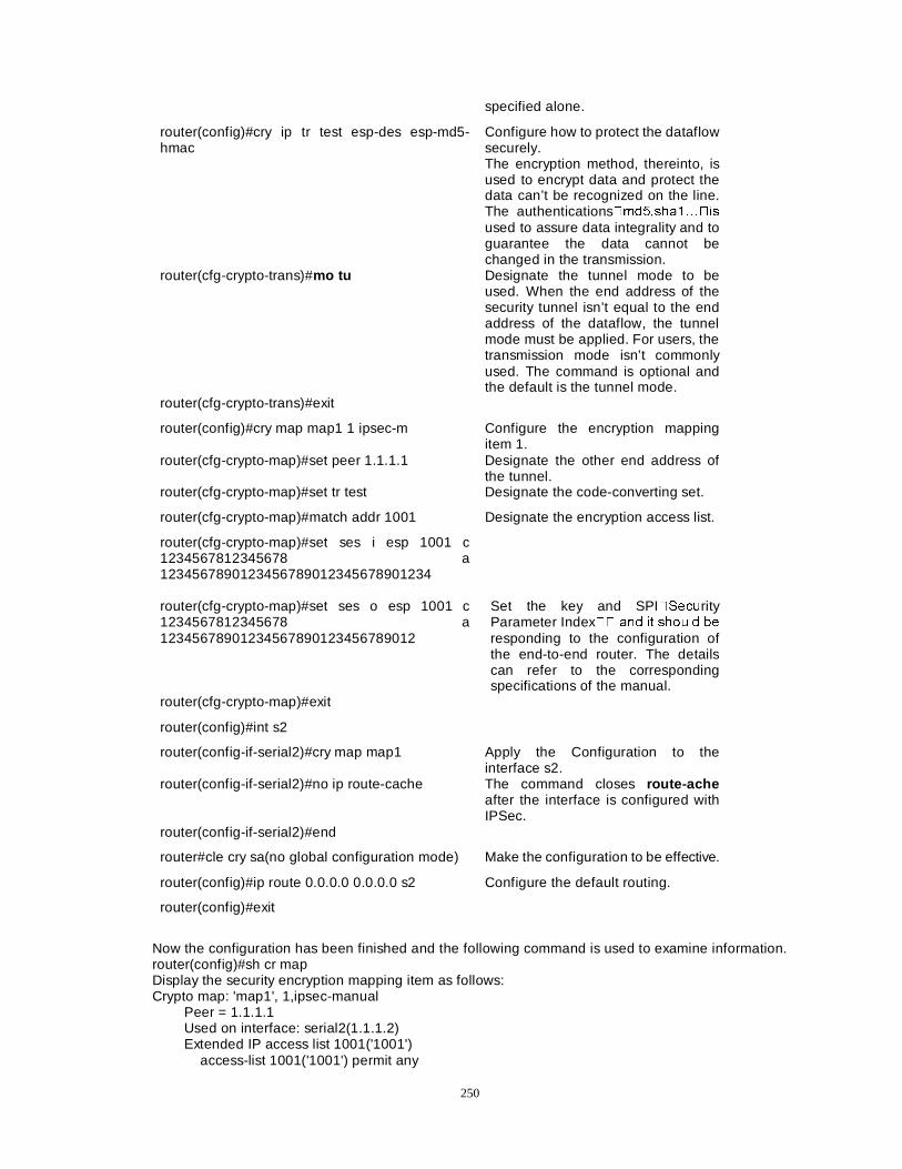
250
specified alone.
router(config)#cry ip tr test esp-des esp-md5-hmac
Configure how to protect the dataflow securely. The encryption method, thereinto, is used to encrypt data and protect the data can’t be recognized on the line. The authentications�PG��VKD�«�LV
used to assure data integrality and to guarantee the data cannot be changed in the transmission.
router(cfg-crypto-trans)#mo tu Designate the tunnel mode to be used. When the end address of the security tunnel isn’t equal to the end address of the dataflow, the tunnel mode must be applied. For users, the transmission mode isn’t commonly used. The command is optional and the default is the tunnel mode.
router(cfg-crypto-trans)#exit
router(config)#cry map map1 1 ipsec-m Configure the encryption mapping item 1.
router(cfg-crypto-map)#set peer 1.1.1.1 Designate the other end address of the tunnel.
router(cfg-crypto-map)#set tr test Designate the code-converting set.
router(cfg-crypto-map)#match addr 1001 Designate the encryption access list.
router(cfg-crypto-map)#set ses i esp 1001 c 1234567812345678 a 1234567890123456789012345678901234
router(cfg-crypto-map)#set ses o esp 1001 c 1234567812345678 a 12345678901234567890123456789012
Set the key and SPI�6HFXrity Parameter Index�� DQG LW VKRXOG EH
responding to the configuration of the end-to-end router. The details can refer to the corresponding specifications of the manual.
router(cfg-crypto-map)#exit
router(config)#int s2
router(config-if-serial2)#cry map map1 Apply the Configuration to the interface s2.
router(config-if-serial2)#no ip route-cache The command closes route-ache after the interface is configured with IPSec.
router(config-if-serial2)#end
router#cle cry sa(no global configuration mode) Make the configuration to be effective.
router(config)#ip route 0.0.0.0 0.0.0.0 s2 Configure the default routing.
router(config)#exit
Now the configuration has been finished and the following command is used to examine information. router(config)#sh cr map Display the security encryption mapping item as follows: Crypto map: 'map1', 1,ipsec-manual Peer = 1.1.1.1 Used on interface: serial2(1.1.1.2) Extended IP access list 1001('1001') access-list 1001('1001') permit any
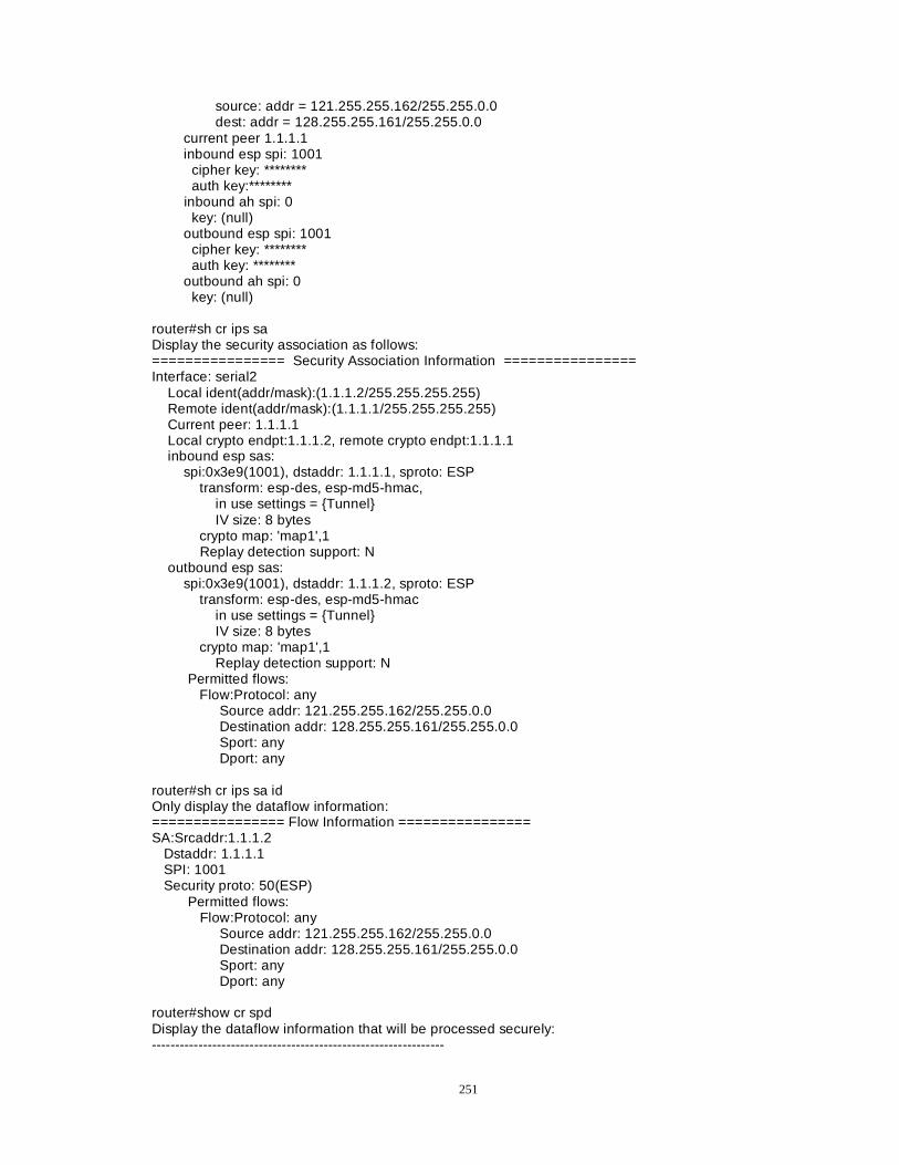
251
source: addr = 121.255.255.162/255.255.0.0 dest: addr = 128.255.255.161/255.255.0.0 current peer 1.1.1.1 inbound esp spi: 1001 cipher key: ******** auth key:******** inbound ah spi: 0 key: (null) outbound esp spi: 1001 cipher key: ******** auth key: ******** outbound ah spi: 0 key: (null) router#sh cr ips sa Display the security association as follows: ================ Security Association Information ================ Interface: serial2 Local ident(addr/mask):(1.1.1.2/255.255.255.255) Remote ident(addr/mask):(1.1.1.1/255.255.255.255) Current peer: 1.1.1.1 Local crypto endpt:1.1.1.2, remote crypto endpt:1.1.1.1 inbound esp sas: spi:0x3e9(1001), dstaddr: 1.1.1.1, sproto: ESP transform: esp-des, esp-md5-hmac, in use settings = {Tunnel} IV size: 8 bytes crypto map: 'map1',1 Replay detection support: N outbound esp sas: spi:0x3e9(1001), dstaddr: 1.1.1.2, sproto: ESP transform: esp-des, esp-md5-hmac in use settings = {Tunnel} IV size: 8 bytes crypto map: 'map1',1 Replay detection support: N Permitted flows: Flow:Protocol: any Source addr: 121.255.255.162/255.255.0.0 Destination addr: 128.255.255.161/255.255.0.0 Sport: any Dport: any router#sh cr ips sa id Only display the dataflow information: ================ Flow Information ================ SA:Srcaddr:1.1.1.2 Dstaddr: 1.1.1.1 SPI: 1001 Security proto: 50(ESP) Permitted flows: Flow:Protocol: any Source addr: 121.255.255.162/255.255.0.0 Destination addr: 128.255.255.161/255.255.0.0 Sport: any Dport: any router#show cr spd Display the dataflow information that will be processed securely: ---------------------------------------------------------------
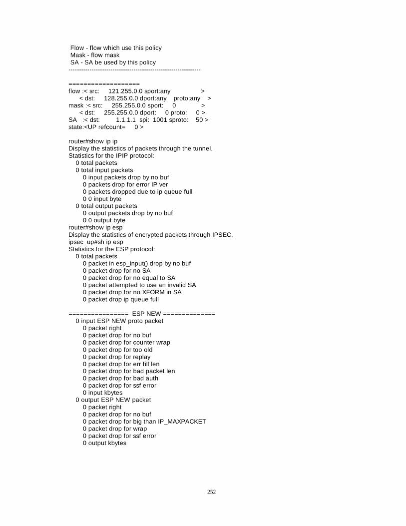
252
Flow - flow which use this policy Mask - flow mask SA - SA be used by this policy --------------------------------------------------------------- =================== flow :< src: 121.255.0.0 sport:any > < dst: 128.255.0.0 dport:any proto:any > mask :< src: 255.255.0.0 sport: 0 > < dst: 255.255.0.0 dport: 0 proto: 0 > SA :< dst: 1.1.1.1 spi: 1001 sproto: 50 > state:<UP refcount= 0 > router#show ip ip Display the statistics of packets through the tunnel. Statistics for the IPIP protocol: 0 total packets 0 total input packets 0 input packets drop by no buf 0 packets drop for error IP ver 0 packets dropped due to ip queue full 0 0 input byte 0 total output packets 0 output packets drop by no buf 0 0 output byte router#show ip esp Display the statistics of encrypted packets through IPSEC. ipsec_up#sh ip esp Statistics for the ESP protocol: 0 total packets 0 packet in esp_input() drop by no buf 0 packet drop for no SA 0 packet drop for no equal to SA 0 packet attempted to use an invalid SA 0 packet drop for no XFORM in SA 0 packet drop ip queue full ================ ESP NEW ============== 0 input ESP NEW proto packet 0 packet right 0 packet drop for no buf 0 packet drop for counter wrap 0 packet drop for too old 0 packet drop for replay 0 packet drop for err fill len 0 packet drop for bad packet len 0 packet drop for bad auth 0 packet drop for ssf error 0 input kbytes 0 output ESP NEW packet 0 packet right 0 packet drop for no buf 0 packet drop for big than IP_MAXPACKET 0 packet drop for wrap 0 packet drop for ssf error 0 output kbytes
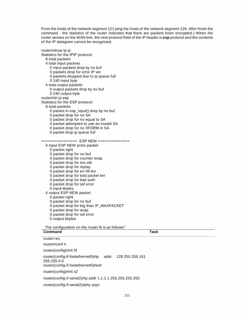
253
From the hosts of the network segment 121 ping the hosts of the network segment 128. After finish the command - the statistics of the router indicates that there are packets been encrypted.) When the router senses on the WAN line, the next protocol field of the IP header is esp protocol and the contents of the IP datagram cannot be recognized. router#show ip ip Statistics for the IPIP protocol: 8 total packets 4 total input packets 0 input packets drop by no buf 0 packets drop for error IP ver 0 packets dropped due to ip queue full 0 240 input byte 4 total output packets 0 output packets drop by no buf 0 240 output byte router#sh ip esp Statistics for the ESP protocol: 8 total packets 0 packet in esp_input() drop by no buf 0 packet drop for no SA 0 packet drop for no equal to SA 0 packet attempted to use an invalid SA 0 packet drop for no XFORM in SA 0 packet drop ip queue full ================ ESP NEW ============== 4 input ESP NEW proto packet 0 packet right 0 packet drop for no buf 0 packet drop for counter wrap 0 packet drop for too old 0 packet drop for replay 0 packet drop for err fill len 0 packet drop for bad packet len 0 packet drop for bad auth 0 packet drop for ssf error 0 input kbytes 4 output ESP NEW packet 0 packet right 0 packet drop for no buf 0 packet drop for big than IP_MAXPACKET 0 packet drop for wrap 0 packet drop for ssf error 0 output kbytes
The configuration on the router B is as follows� Command Task
router>en
router#conf n
router(config)#int f0
router(config-if-fastethernet0)#ip addr 128.255.255.161 255.255.0.0
router(config-if-fastethernet0)#exit
router(config)#int s2
router(config-if-serial2)#ip addr 1.1.1.1 255.255.255.255
router(config-if-serial2)#phy asyn
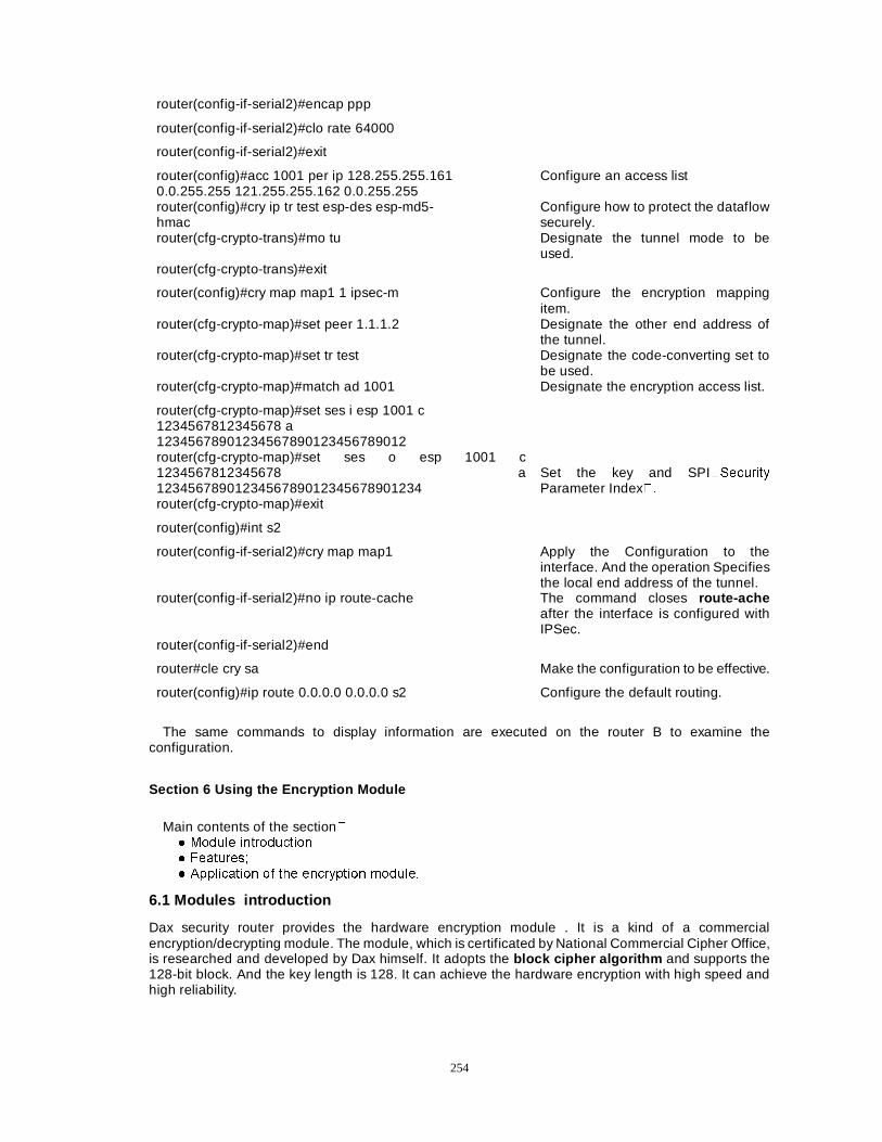
254
router(config-if-serial2)#encap ppp
router(config-if-serial2)#clo rate 64000
router(config-if-serial2)#exit
router(config)#acc 1001 per ip 128.255.255.161 0.0.255.255 121.255.255.162 0.0.255.255
Configure an access list
router(config)#cry ip tr test esp-des esp-md5- hmac
Configure how to protect the dataflow securely.
router(cfg-crypto-trans)#mo tu Designate the tunnel mode to be used.
router(cfg-crypto-trans)#exit
router(config)#cry map map1 1 ipsec-m Configure the encryption mapping item.
router(cfg-crypto-map)#set peer 1.1.1.2 Designate the other end address of the tunnel.
router(cfg-crypto-map)#set tr test Designate the code-converting set to be used.
router(cfg-crypto-map)#match ad 1001 Designate the encryption access list.
router(cfg-crypto-map)#set ses i esp 1001 c 1234567812345678 a 12345678901234567890123456789012
router(cfg-crypto-map)#set ses o esp 1001 c 1234567812345678 a 1234567890123456789012345678901234
Set the key and SPI�6HFXULW\Parameter Index��
router(cfg-crypto-map)#exit
router(config)#int s2
router(config-if-serial2)#cry map map1 Apply the Configuration to the interface. And the operation Specifies the local end address of the tunnel.
router(config-if-serial2)#no ip route-cache The command closes route-ache after the interface is configured with IPSec.
router(config-if-serial2)#end
router#cle cry sa Make the configuration to be effective.
router(config)#ip route 0.0.0.0 0.0.0.0 s2 Configure the default routing.
The same commands to display information are executed on the router B to examine the
configuration.
Section 6 Using the Encryption Module
Main contents of the section� � 0RGXOH LQWURGXFWLRQ � )HDWXUHV� � $SSOLFDWLRQ RI WKH HQFU\SWLRQ PRGXOH�
6.1 Modules introduction
Dax security router provides the hardware encryption module . It is a kind of a commercial encryption/decrypting module. The module, which is certificated by National Commercial Cipher Office, is researched and developed by Dax himself. It adopts the block cipher algorithm and supports the 128-bit block. And the key length is 128. It can achieve the hardware encryption with high speed and high reliability.
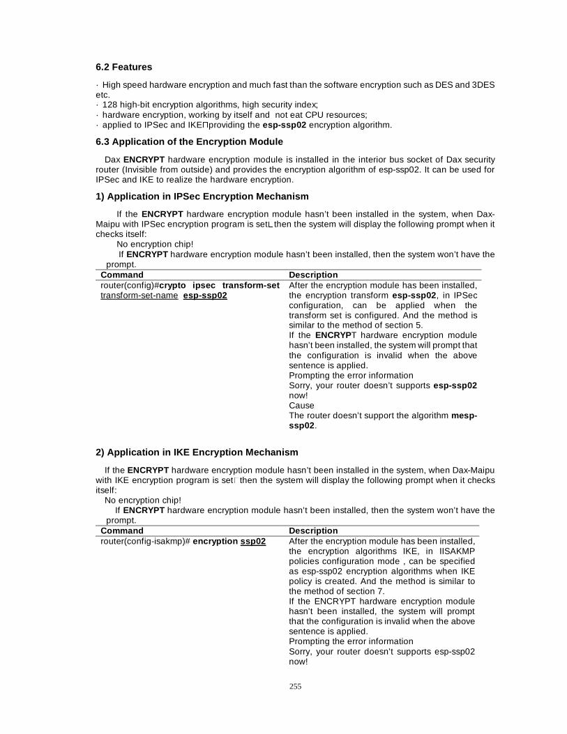
255
6.2 Features
· High speed hardware encryption and much fast than the software encryption such as DES and 3DES etc. · 128 high-bit encryption algorithms, high security index; · hardware encryption, working by itself and not eat CPU resources; · applied to IPSec and IKE�providing the esp-ssp02 encryption algorithm.
6.3 Application of the Encryption Module
Dax ENCRYPT hardware encryption module is installed in the interior bus socket of Dax security router (Invisible from outside) and provides the encryption algorithm of esp-ssp02. It can be used for IPSec and IKE to realize the hardware encryption.
1) Application in IPSec Encryption Mechanism
If the ENCRYPT hardware encryption module hasn’t been installed in the system, when Dax-Maipu with IPSec encryption program is set�then the system will display the following prompt when it checks itself:
No encryption chip! If ENCRYPT hardware encryption module hasn’t been installed, then the system won’t have the
prompt. Command Description router(config)#crypto ipsec transform-set transform-set-name esp-ssp02
After the encryption module has been installed, the encryption transform esp-ssp02 , in IPSec configuration, can be applied when the transform set is configured. And the method is similar to the method of section 5. If the ENCRYPT hardware encryption module hasn’t been installed, the system will prompt that the configuration is invalid when the above sentence is applied. Prompting the error information Sorry, your router doesn’t supports esp-ssp02 now! Cause The router doesn’t support the algorithm mesp-ssp02 .
2) Application in IKE Encryption Mechanism
If the ENCRYPT hardware encryption module hasn’t been installed in the system, when Dax-Maipu with IKE encryption program is set�then the system will display the following prompt when it checks itself:
No encryption chip! If ENCRYPT hardware encryption module hasn’t been installed, then the system won’t have the
prompt. Command Description router(config-isakmp)# encryption ssp02 After the encryption module has been installed,
the encryption algorithms IKE, in IISAKMP policies configuration mode , can be specified as esp-ssp02 encryption algorithms when IKE policy is created. And the method is similar to the method of section 7. If the ENCRYPT hardware encryption module hasn’t been installed, the system will prompt that the configuration is invalid when the above sentence is applied. Prompting the error information Sorry, your router doesn’t supports esp-ssp02 now!
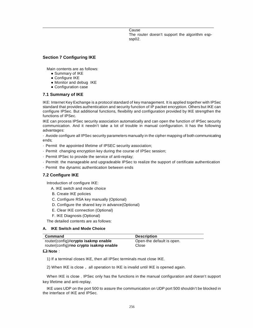
256
Cause The router doesn’t support the algorithm esp-ssp02.
Section 7 Configuring IKE
Main contents are as follows: � Summary of IKE � Configure IKE � Monitor and debug IKE � Configuration case
7.1 Summary of IKE
IKE: Internet Key Exchange is a protocol standard of key management. It is applied together with IPSec standard that provides authentication and security function of IP packet encryption. Others but IKE can configure IPSec. But additional functions, flexibility and configuration provided by IKE strengthen the functions of IPSec. IKE can process IPSec security association automatically and can open the function of IPSec security communication. And it needn’t take a lot of trouble in manual configuration. It has the following advantages: · Avoide configure all IPSec security parameters manually in the cipher mapping of both communicating ends; · Permit the appointed lifetime of IPSEC security association; · Permit changing encryption key during the course of IPSec session; · Permit IPSec to provide the service of anti-replay; · Permitt the manageable and upgradeable IPSec to realize the support of certificate authentication · Permit the dynamic authentication between ends
7.2 Configure IKE
Introduction of configure IKE: A. IKE switch and mode choice B. Create IKE policies C. Configure RSA key manually (Optional) D. Configure the shared key in advance(Optional) E. Clear IKE connection (Optional) F. IKE Diagnosis (Optional)
The detailed contents are as follows:
A. IKE Switch and Mode Choice
Command Description router(config)#crypto isakmp enable Open-the default is open. router(config)#no crypto isakmp enable Close
NoteÛÛ
1) If a terminal closes IKE, then all IPSec terminals must close IKE.
2) When IKE is closeÍ all operation to IKE is invalid until IKE is opened again.
When IKE is closeÍIPSec only has the functions in the manual configuration and doesn’t support key lifetime and anti-replay.
IKE uses UDP on the port 500 to assure the communication on UDP port 500 shouldn’t be blocked in the interface of IKE and IPSec.

257
IKE mode choice
Command Description
router(config)#crypto ikemode {standard|mpike}
Standard The standard IKE negotiation procedure is the default.
mpike the mended and strengthened IKE negotiation procedure
In the manner, the whole negotiation procedure of IKE adopts the security protection. (�������� �����
B. Create IKE Policies
IKE policies describes which security parameters are applied to protect subsequent IKE negotiation. After two terminals agree on a policy with each other, the security parameters of the policy are identified by the security association (SA) of each terminal. During the course of the negotiation, the security association is applied to the subsequent IKE communication. Each IKE policy has the following parameters:
· Encryption arithmetic · Hash arithmetic · Authenticating method · Diffie-Hellman groupware identification · Lifetime of IKE security association
The following commands are executed as the following steps to configure the security policy�
The first step: The command is used in the global mode to enter ISAKMP policy configuration (config-isakmp) mode.
Command Description router(config)#crypto isakmp policy priority
Priority Priority�1—10000�IKE policy identity�The default is least.
router(config)#no crypto isakmp policy [priority]
Cancel an IKE policy.
Example:
Command Task router(config)# crypto isa po 123 Create an IKE policy with the priority 123 and
enter config-isakmp configuration mode. The second step: Use the command to designate IKE encryption method in ISAKMP policy configuration mode:
Command Description router(config-isakmp)# encryption des|3des|blowfish|ssp02
des Designate the encryption method des to be used. 3des Designate the encryption method 3des to be used. blowfish Designate the encryption method blowfish to be used. ssp02 Designate the encryption method ssp02 to be used(using a hardware encryption module).
router(config-isakmp)# no encryption Renew IKE encryption method back to the default arithmetic (des ).
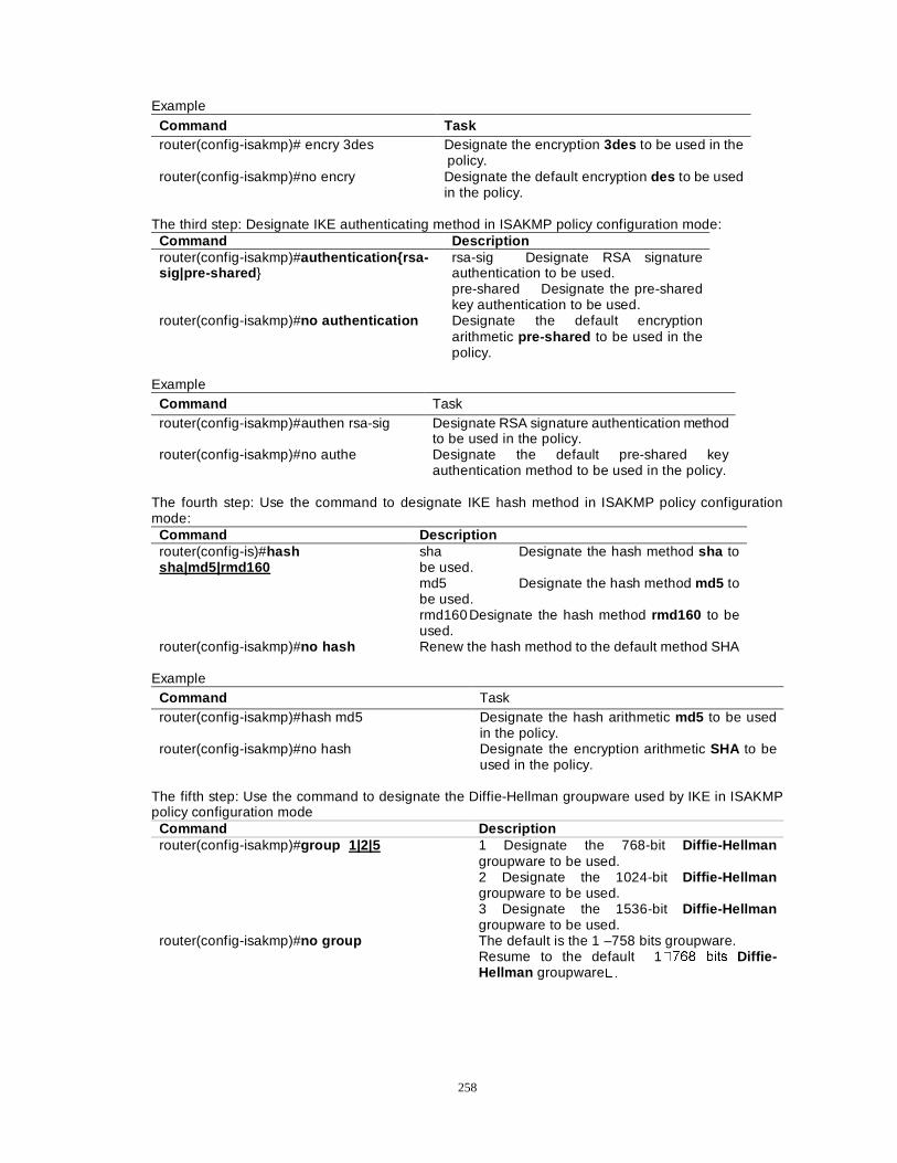
258
Example Command Task router(config-isakmp)# encry 3des Designate the encryption 3des to be used in the
policy. router(config-isakmp)#no encry Designate the default encryption des to be used
in the policy. The third step: Designate IKE authenticating method in ISAKMP policy configuration mode:
Command Description router(config-isakmp)#authentication{rsa-sig|pre-shared }
rsa-sig Designate RSA signature authentication to be used. pre-shared Designate the pre-shared key authentication to be used.
router(config-isakmp)#no authentication Designate the default encryption arithmetic pre-shared to be used in the policy.
Example
Command Task router(config-isakmp)#authen rsa-sig Designate RSA signature authentication method
to be used in the policy. router(config-isakmp)#no authe Designate the default pre-shared key
authentication method to be used in the policy. The fourth step: Use the command to designate IKE hash method in ISAKMP policy configuration mode:
Command Description router(config-is)#hash sha|md5|rmd160
sha Designate the hash method sha to be used. md5 Designate the hash method md5 to be used. rmd160 Designate the hash method rmd160 to be used.
router(config-isakmp)#no hash Renew the hash method to the default method SHA Example
Command Task router(config-isakmp)#hash md5 Designate the hash arithmetic md5 to be used
in the policy. router(config-isakmp)#no hash Designate the encryption arithmetic SHA to be
used in the policy. The fifth step: Use the command to designate the Diffie-Hellman groupware used by IKE in ISAKMP policy configuration mode
Command Description router(config-isakmp)#group 1|2|5 1 Designate the 768-bit Diffie-Hellman
groupware to be used. 2 Designate the 1024-bit Diffie-Hellman groupware to be used. 3 Designate the 1536-bit Diffie-Hellman groupware to be used.
router(config-isakmp)#no group The default is the 1 –758 bits groupware. Resume to the default 1���� ELWV Diffie-Hellman groupware��
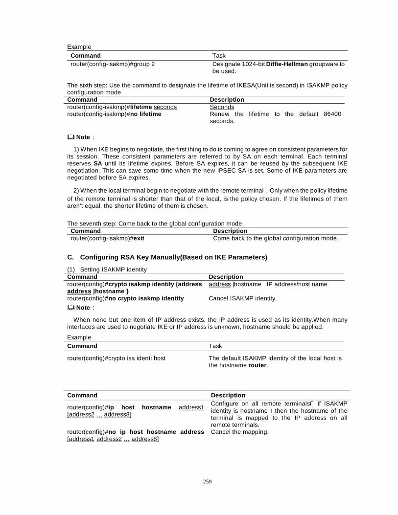
259
Example Command Task router(config-isakmp)#group 2
Designate 1024-bit Diffie-Hellman groupware to be used.
The sixth step: Use the command to designate the lifetime of IKESA(Unit is second) in ISAKMP policy configuration mode Command Description router(config-isakmp)#lifetime seconds Seconds router(config-isakmp)#no lifetime Renew the lifetime to the default 86400
seconds.
NoteÛÛ
1) When IKE begins to negotiate, the first thing to do is coming to agree on consistent parameters for its session. These consistent parameters are referred to by SA on each terminal. Each terminal reserves SA until its lifetime expires. Before SA expires, it can be reused by the subsequent IKE negotiation. This can save some time when the new IPSEC SA is set. Some of IKE parameters are negotiated before SA expires.
2) When the local terminal begin to negotiate with the remote terminalÍOnly when the policy lifetime of the remote terminal is shorter than that of the local, is the policy chosen. If the lifetimes of them aren’t equal, the shorter lifetime of them is chosen.
The seventh step: Come back to the global configuration mode
Command Description router(config-isakmp)#exit Come back to the global configuration mode.
C. Configuring RSA Key Manually(Based on IKE Parameters)
(1) Setting ISAKMP identity Command Description router(config)#crypto isakmp identity {address address |hostname }
address |hostname IP address/host name
router(config)#no crypto isakmp identity Cancel ISAKMP identity.
NoteÛÛ
When none but one item of IP address exists, the IP address is used as its identity.When many interfaces are used to negotiate IKE or IP address is unknown, hostname should be applied.
Example Command Task
router(config)#crypto isa identi host The default ISAKMP identity of the local host is the hostname router .
Command Description
router(config)#ip host hostname address1 [address2 … address8]
Configure on all remote terminals� if ISAKMP identity is hostname� then the hostname of the terminal is mapped to the IP address on all remote terminals.
router(config)#no ip host hostname address [address1 address2 … address8]
Cancel the mapping.
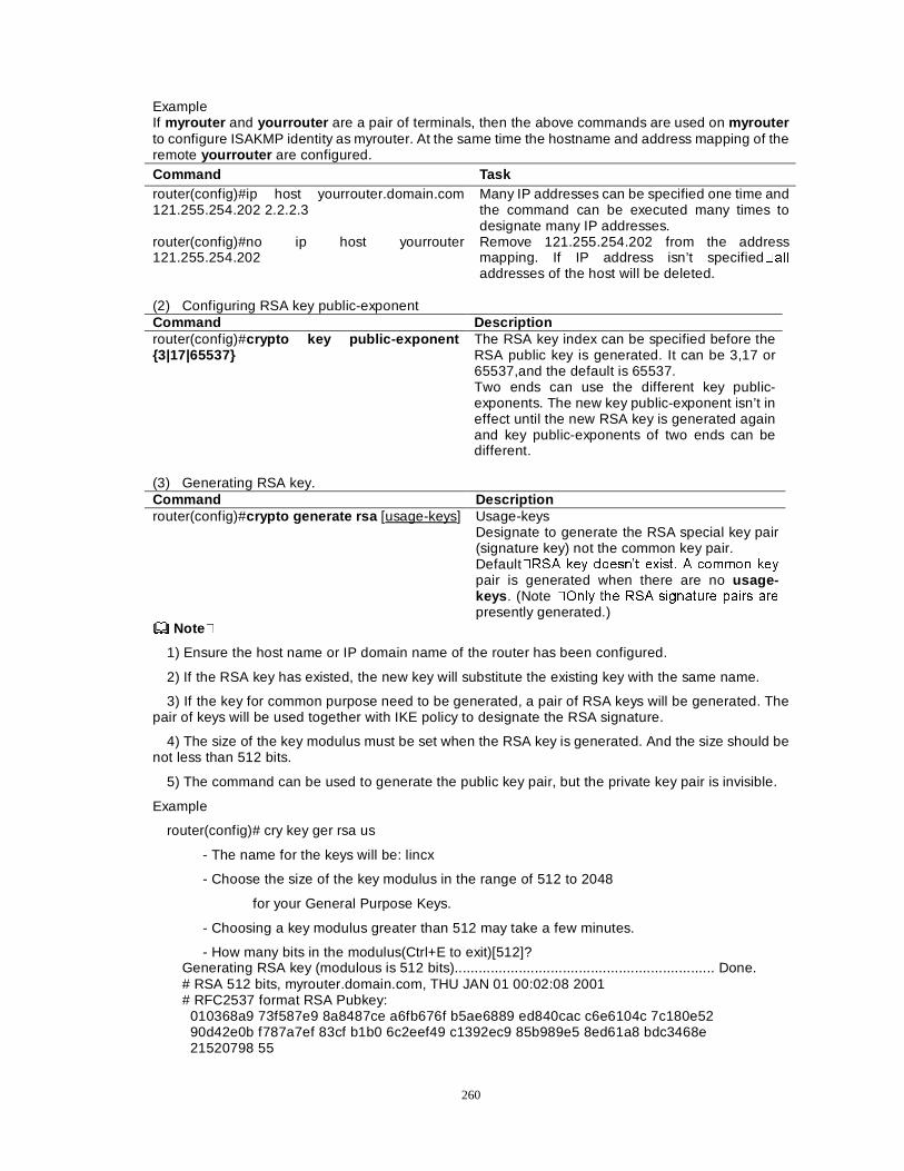
260
Example If myrouter and yourrouter are a pair of terminals, then the above commands are used on myrouter to configure ISAKMP identity as myrouter. At the same time the hostname and address mapping of the remote yourrouter are configured. Command Task router(config)#ip host yourrouter.domain.com 121.255.254.202 2.2.2.3
Many IP addresses can be specified one time and the command can be executed many times to designate many IP addresses.
router(config)#no ip host yourrouter 121.255.254.202
Remove 121.255.254.202 from the address mapping. If IP address isn’t specified�DOOaddresses of the host will be deleted.
(2) Configuring RSA key public-exponent Command Description router(config)#crypto key public-exponent {3|17|65537}
The RSA key index can be specified before the RSA public key is generated. It can be 3,17 or 65537,and the default is 65537. Two ends can use the different key public-exponents. The new key public-exponent isn’t in effect until the new RSA key is generated again and key public-exponents of two ends can be different.
(3) Generating RSA key. Command Description router(config)#crypto generate rsa [usage-keys] Usage-keys
Designate to generate the RSA special key pair (signature key) not the common key pair. Default�56$ NH\ GRHVQ¶W H[LVW� $ FRPPRQ NH\
pair is generated when there are no usage-keys . (Note �2QO\ WKH 56$ VLJQDWXUH SDLUV DUH
presently generated.) Note�
1) Ensure the host name or IP domain name of the router has been configured.
2) If the RSA key has existed, the new key will substitute the existing key with the same name.
3) If the key for common purpose need to be generated, a pair of RSA keys will be generated. The pair of keys will be used together with IKE policy to designate the RSA signature.
4) The size of the key modulus must be set when the RSA key is generated. And the size should be not less than 512 bits.
5) The command can be used to generate the public key pair, but the private key pair is invisible.
Example
router(config)# cry key ger rsa us
- The name for the keys will be: lincx
- Choose the size of the key modulus in the range of 512 to 2048
for your General Purpose Keys.
- Choosing a key modulus greater than 512 may take a few minutes.
- How many bits in the modulus(Ctrl+E to exit)[512]? Generating RSA key (modulous is 512 bits)................................................................. Done. # RSA 512 bits, myrouter.domain.com, THU JAN 01 00:02:08 2001 # RFC2537 format RSA Pubkey: 010368a9 73f587e9 8a8487ce a6fb676f b5ae6889 ed840cac c6e6104c 7c180e52 90d42e0b f787a7ef 83cf b1b0 6c2eef49 c1392ec9 85b989e5 8ed61a8 bdc3468e 21520798 55
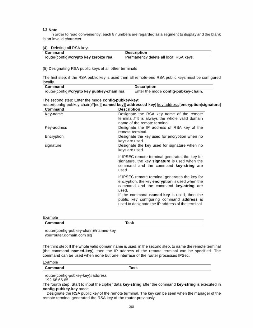
261
Note In order to read conveniently, each 8 numbers are regarded as a segment to display and the blank
is an invalid character.
(4) Deleting all RSA keys Command Description router(config)#crypto key zeroize rsa Permanently delete all local RSA keys.
(5) Designating RSA public keys of all other terminals The first step: if the RSA public key is used then all remote-end RSA public keys must be configured locally.
Command Description router(config)#crypto key pubkey-chain rsa Enter the mode config-pubkey-chain.
The second step: Enter the mode config-pubkey-key : router(config-pubkey-chain)#[no][ named -key][ addressed -key] key-address [encryption |signature ]
Command Description Key-name Designate the RSA key name of the remote
terminal.�It is always the whole valid domain name of the remote terminal.�
Key-address Designate the IP address of RSA key of the remote terminal.
Encryption Designate the key used for encryption when no keys are used.
signature Designate the key used for signature when no keys are used.
If IPSEC remote terminal generates the key for signature, the key signature is used when the command and the command key-string are used.
If IPSEC remote terminal generates the key for encryption, the key encryption is used when the command and the command key-string are used. If the command named-key is used, then the public key configuring command address is used to designate the IP address of the terminal.
Example Command Task
router(config-pubkey-chain)#named-key yourrouter.domain.com sig
The third step: If the whole valid domain name is used, in the second step, to name the remote terminal (the command named-key ), then the IP address of the remote terminal can be specified. The command can be used when none but one interface of the router processes IPSec.
Example Command Task
router(config-pubkey-key)#address 192.68.66.65
The fourth step: Start to input the cipher data key-string after the command key-string is executed in config-pubkey-key mode.
Designate the RSA public key of the remote terminal. The key can be seen when the manager of the remote terminal generated the RSA key of the router previously.
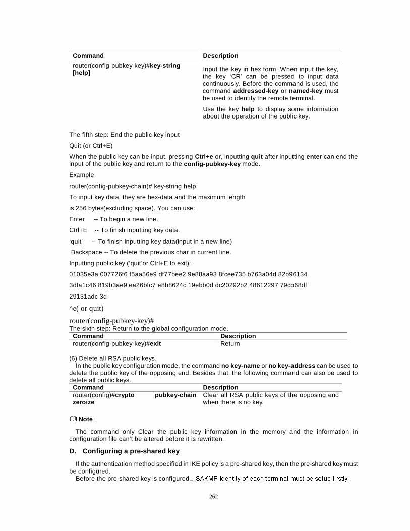
262
Command Description
router(config-pubkey-key)#key-string [help] Input the key in hex form. When input the key,
the key ‘CR’ can be pressed to input data continuously. Before the command is used, the command addressed-key or named-key must be used to identify the remote terminal.
Use the key help to display some information about the operation of the public key.
The fifth step: End the public key input
Quit (or Ctrl+E)
When the public key can be input, pressing Ctrl+e or, inputting quit after inputting enter can end the input of the public key and return to the config-pubkey-key mode.
Example
router(config-pubkey-chain)# key-string help
To input key data, they are hex-data and the maximum length
is 256 bytes(excluding space). You can use:
Enter -- To begin a new line.
Ctrl+E -- To finish inputting key data.
‘quit’ -- To finish inputting key data(input in a new line)
Backspace -- To delete the previous char in current line.
Inputting public key (‘quit’or Ctrl+E to exit):
01035e3a 007726f6 f5aa56e9 df77bee2 9e88aa93 8fcee735 b763a04d 82b96134
3dfa1c46 819b3ae9 ea26bfc7 e8b8624c 19ebb0d dc20292b2 48612297 79cb68df
29131adc 3d
^e( or quit)
router(config-pubkey-key)# The sixth step: Return to the global configuration mode.
Command Description router(config-pubkey-key)#exit Return
(6) Delete all RSA public keys.
In the public key configuration mode, the command no key-name or no key-address can be used to delete the public key of the opposing end. Besides that, the following command can also be used to delete all public keys.
Command Description router(config)#crypto pubkey-chain zeroize
Clear all RSA public keys of the opposing end when there is no key.
NoteÛÛ
The command only Clear the public key information in the memory and the information in configuration file can’t be altered before it is rewritten.
D. Configuring a pre-shared key
If the authentication method specified in IKE policy is a pre-shared key, then the pre-shared key must be configured.
Before the pre-shared key is configured�,6$.03 LGHQWLW\ RI HDFK WHUPLQDO PXVW EH VHWXS ILUVWO\�
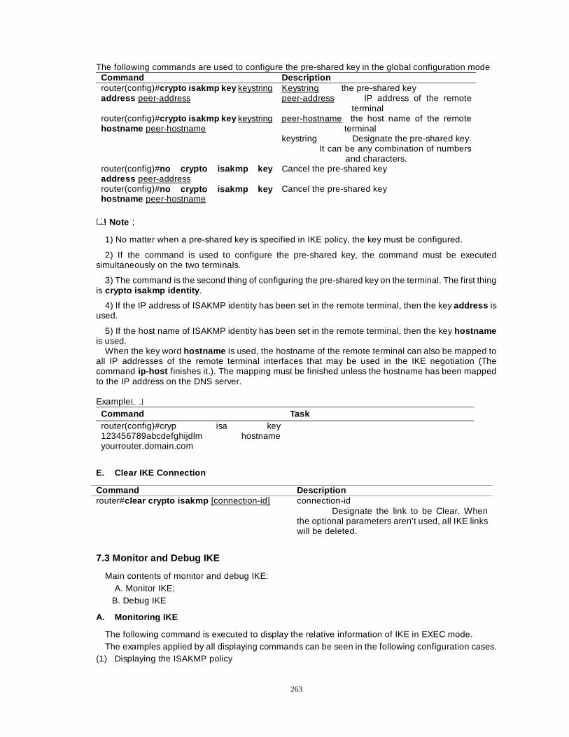
263
The following commands are used to configure the pre-shared key in the global configuration mode� Command Description router(config)#crypto isakmp key keystring address peer-address
Keystring the pre-shared key peer-address IP address of the remote
terminal router(config)#crypto isakmp key keystring hostname peer-hostname
peer-hostname the host name of the remote terminal
keystring Designate the pre-shared key. It can be any combination of numbers
and characters. router(config)#no crypto isakmp key address peer-address
Cancel the pre-shared key
router(config)#no crypto isakmp key hostname peer-hostname
Cancel the pre-shared key
NoteÛÛ
1) No matter when a pre-shared key is specified in IKE policy, the key must be configured.
2) If the command is used to configure the pre-shared key, the command must be executed simultaneously on the two terminals.
3) The command is the second thing of configuring the pre-shared key on the terminal. The first thing is crypto isakmp identity .
4) If the IP address of ISAKMP identity has been set in the remote terminal, then the key address is used.
5) If the host name of ISAKMP identity has been set in the remote terminal, then the key hostname is used.
When the key word hostname is used, the hostname of the remote terminal can also be mapped to all IP addresses of the remote terminal interfaces that may be used in the IKE negotiation (The command ip-host finishes it.). The mapping must be finished unless the hostname has been mapped to the IP address on the DNS server. Example��
Command Task router(config)#cryp isa key 123456789abcdefghijdlm hostname yourrouter.domain.com
E. Clear IKE Connection
Command Description router#clear crypto isakmp [connection-id] connection-id
Designate the link to be Clear. When the optional parameters aren’t used, all IKE links will be deleted.
7.3 Monitor and Debug IKE
Main contents of monitor and debug IKE: A. Monitor IKE;
B. Debug IKE
A. Monitoring IKE
The following command is executed to display the relative information of IKE in EXEC mode. The examples applied by all displaying commands can be seen in the following configuration cases.
(1) Displaying the ISAKMP policy
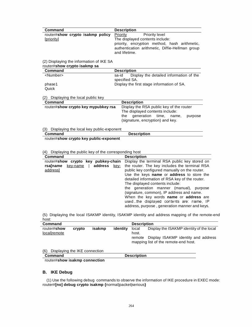
264
Command Description router#show crypto isakmp policy [priority]
Priority Priority level The displayed contents include: priority, encryption method, hash arithmetic, authentication arithmetic, Diffie-Hellman group and lifetime.
(2) Displaying the information of IKE SA router#show crypto isakmp sa
Command Description <Number> sa-id Display the detailed information of the
specified SA. phase1 Display the first stage information of SA. Quick
(2) Displaying the local public key
Command Description router#show crypto key mypubkey rsa Display the RSA public key of the router
The displayed contents include: the generation time, name, purpose (signature, encryption) and key.
(3) Displaying the local key public-exponent
Command Description router#show crypto key public-exponent
(4) Displaying the public key of the corresponding host
Command Description router#show crypto key pubkey-chain rsa[name key-name | address key-address]
Display the terminal RSA public key stored on the router. The key includes the terminal RSA public key configured manually on the router. Use the keys name or address to store the detailed information of RSA key of the router. The displayed contents include: the generation manner (manual), purpose (signature, common), IP address and name. When the key words name or address are used�WKH GLVSOD\HG FRQWHQWV DUH� QDPH� ,3
address, purpose , generation manner and keys. (5) Displaying the local ISAKMP identity, ISAKMP identity and address mapping of the remote-end host: Command Description router#show crypto isakmp identity local|remote
local Display the ISAKMP identity of the local host. remote Display ISAKMP identity and address mapping list of the remote-end host.
(6) Displaying the IKE connection
Command Description router#show isakmp connection
B. IKE Debug
(1) Use the following debug commands to observe the information of IKE procedure in EXEC mode: router#[no] debug crypto isakmp { normal|packet|serious}
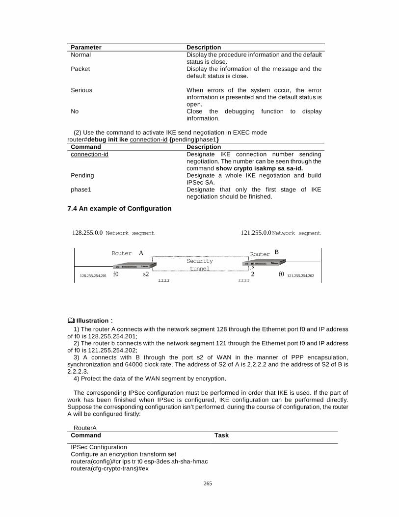
265
Parameter Description Normal Display the procedure information and the default
status is close. Packet Display the information of the message and the
default status is close.
Serious When errors of the system occur, the error information is presented and the default status is open.
No Close the debugging function to display information.
(2) Use the command to activate IKE send negotiation in EXEC mode
router#debug init ike connection-id {pending|phase1} Command Description connection-id Designate IKE connection number sending
negotiation. The number can be seen through the command show crypto isakmp sa sa-id.
Pending Designate a whole IKE negotiation and build IPSec SA.
phase1 Designate that only the first stage of IKE negotiation should be finished.
7.4 An example of Configuration
Router A
f0
B
s2 f0
Securitytunnel
128.255.254.2012.2.2.2 2.2.2.3
121.255.254.202
128.255.0.0Network segment 121.255.0.0
s2
Network segment
Router
Illustration ÛÛ
1) The router A connects with the network segment 128 through the Ethernet port f0 and IP address of f0 is 128.255.254.201;
2) The router b connects with the network segment 121 through the Ethernet port f0 and IP address of f0 is 121.255.254.202;
3) A connects with B through the port s2 of WAN in the manner of PPP encapsulation, synchronization and 64000 clock rate. The address of S2 of A is 2.2.2.2 and the address of S2 of B is 2.2.2.3.
4) Protect the data of the WAN segment by encryption.
The corresponding IPSec configuration must be performed in order that IKE is used. If the part of work has been finished when IPSec is configured, IKE configuration can be performed directly. Suppose the corresponding configuration isn’t performed, during the course of configuration, the router A will be configured firstly:
RouterA
Command Task
IPSec Configuration Configure an encryption transform set routera(config)#cr ips tr t0 esp-3des ah-sha-hmac routera(cfg-crypto-trans)#ex
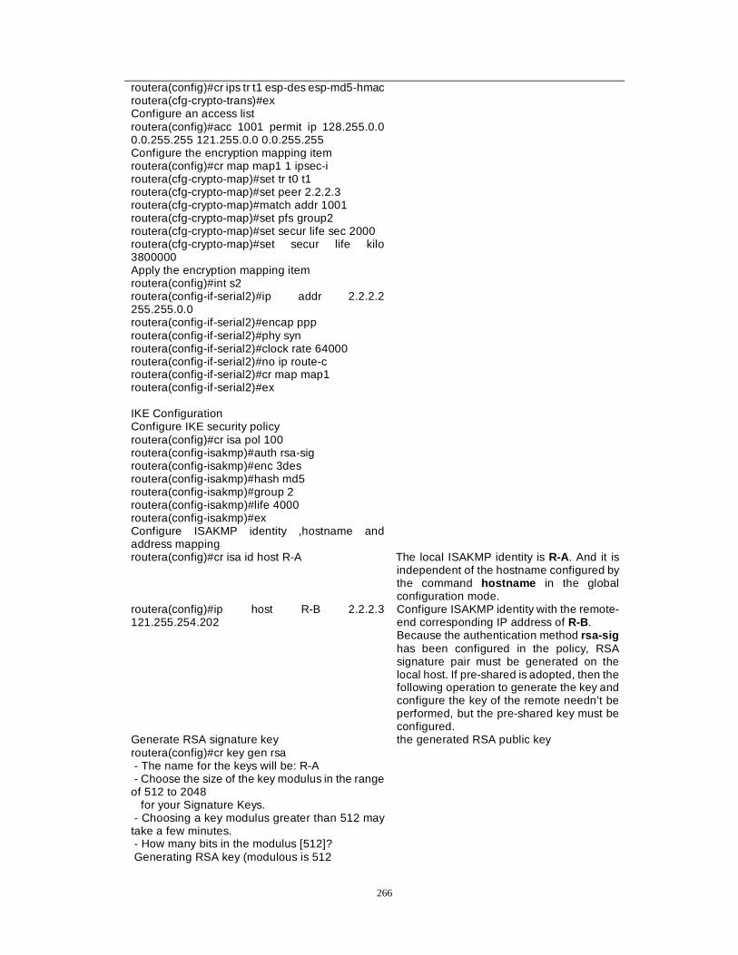
266
routera(config)#cr ips tr t1 esp-des esp-md5-hmac routera(cfg-crypto-trans)#ex Configure an access list routera(config)#acc 1001 permit ip 128.255.0.0 0.0.255.255 121.255.0.0 0.0.255.255 Configure the encryption mapping item routera(config)#cr map map1 1 ipsec-i routera(cfg-crypto-map)#set tr t0 t1 routera(cfg-crypto-map)#set peer 2.2.2.3 routera(cfg-crypto-map)#match addr 1001 routera(cfg-crypto-map)#set pfs group2 routera(cfg-crypto-map)#set secur life sec 2000 routera(cfg-crypto-map)#set secur life kilo 3800000 Apply the encryption mapping item routera(config)#int s2 routera(config-if-serial2)#ip addr 2.2.2.2 255.255.0.0 routera(config-if-serial2)#encap ppp routera(config-if-serial2)#phy syn routera(config-if-serial2)#clock rate 64000 routera(config-if-serial2)#no ip route-c routera(config-if-serial2)#cr map map1 routera(config-if-serial2)#ex IKE Configuration Configure IKE security policy routera(config)#cr isa pol 100 routera(config-isakmp)#auth rsa-sig routera(config-isakmp)#enc 3des routera(config-isakmp)#hash md5 routera(config-isakmp)#group 2 routera(config-isakmp)#life 4000 routera(config-isakmp)#ex
Configure ISAKMP identity ,hostname and address mapping
routera(config)#cr isa id host R-A The local ISAKMP identity is R-A. And it is independent of the hostname configured by the command hostname in the global configuration mode.
routera(config)#ip host R-B 2.2.2.3 121.255.254.202
Configure ISAKMP identity with the remote-end corresponding IP address of R-B. Because the authentication method rsa-sig has been configured in the policy, RSA signature pair must be generated on the local host. If pre-shared is adopted, then the following operation to generate the key and configure the key of the remote needn’t be performed, but the pre-shared key must be configured.
Generate RSA signature key routera(config)#cr key gen rsa - The name for the keys will be: R-A - Choose the size of the key modulus in the range of 512 to 2048 for your Signature Keys. - Choosing a key modulus greater than 512 may take a few minutes. - How many bits in the modulus [512]? Generating RSA key (modulous is 512
the generated RSA public key
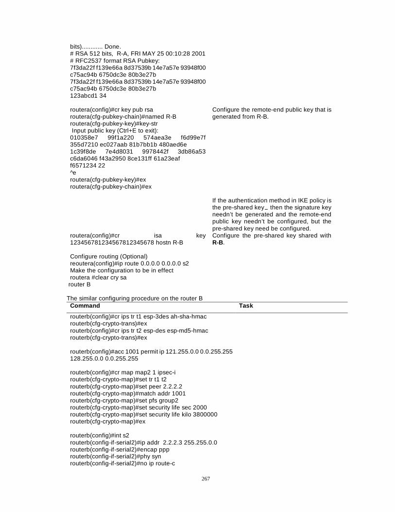
267
bits)............ Done. # RSA 512 bits, R-A, FRI MAY 25 00:10:28 2001 # RFC2537 format RSA Pubkey: 7f3da22f f139e66a 8d37539b 14e7a57e 93948f00 c75ac94b 6750dc3e 80b3e27b 7f3da22f f139e66a 8d37539b 14e7a57e 93948f00 c75ac94b 6750dc3e 80b3e27b 123abcd1 34 routera(config)#cr key pub rsa routera(cfg-pubkey-chain)#named R-B routera(cfg-pubkey-key)#key-str Input public key (Ctrl+E to exit): 010358e7 99f1a220 574aea3e f6d99e7f 355d7210 ec027aab 81b7bb1b 480aed6e 1c39f8de 7e4d8031 9978442f 3db86a53 c6da6046 f43a2950 8ce131ff 61a23eaf f6571234 22 ^e routera(cfg-pubkey-key)#ex routera(cfg-pubkey-chain)#ex
Configure the remote-end public key that is generated from R-B.
If the authentication method in IKE policy is the pre-shared key� then the signature key needn’t be generated and the remote-end public key needn’t be configured, but the pre-shared key need be configured.
routera(config)#cr isa key 123456781234567812345678 hostn R-B
Configure the pre-shared key shared with R-B.
Configure routing (Optional) reoutera(config)#ip route 0.0.0.0 0.0.0.0 s2 Make the configuration to be in effect routera #clear cry sa
router B The similar configuring procedure on the router B
Command Task
routerb(config)#cr ips tr t1 esp-3des ah-sha-hmac routerb(cfg-crypto-trans)#ex routerb(config)#cr ips tr t2 esp-des esp-md5-hmac routerb(cfg-crypto-trans)#ex routerb(config)#acc 1001 permit ip 121.255.0.0 0.0.255.255 128.255.0.0 0.0.255.255 routerb(config)#cr map map2 1 ipsec-i routerb(cfg-crypto-map)#set tr t1 t2 routerb(cfg-crypto-map)#set peer 2.2.2.2 routerb(cfg-crypto-map)#match addr 1001 routerb(cfg-crypto-map)#set pfs group2 routerb(cfg-crypto-map)#set security life sec 2000 routerb(cfg-crypto-map)#set security life kilo 3800000 routerb(cfg-crypto-map)#ex routerb(config)#int s2 routerb(config-if-serial2)#ip addr 2.2.2.3 255.255.0.0 routerb(config-if-serial2)#encap ppp routerb(config-if-serial2)#phy syn routerb(config-if-serial2)#no ip route-c
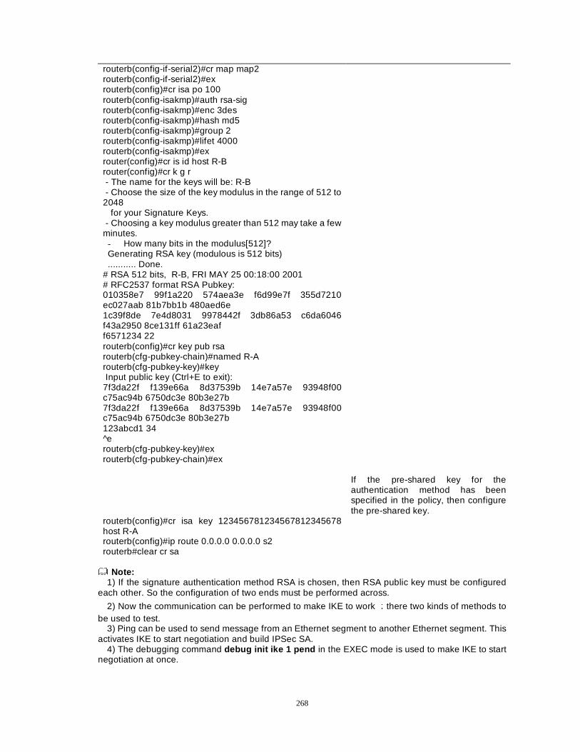
268
routerb(config-if-serial2)#cr map map2 routerb(config-if-serial2)#ex routerb(config)#cr isa po 100 routerb(config-isakmp)#auth rsa-sig routerb(config-isakmp)#enc 3des routerb(config-isakmp)#hash md5 routerb(config-isakmp)#group 2 routerb(config-isakmp)#lifet 4000 routerb(config-isakmp)#ex router(config)#cr is id host R-B router(config)#cr k g r - The name for the keys will be: R-B - Choose the size of the key modulus in the range of 512 to 2048 for your Signature Keys. - Choosing a key modulus greater than 512 may take a few minutes. - How many bits in the modulus[512]? Generating RSA key (modulous is 512 bits) ........... Done.
# RSA 512 bits, R-B, FRI MAY 25 00:18:00 2001 # RFC2537 format RSA Pubkey: 010358e7 99f1a220 574aea3e f6d99e7f 355d7210 ec027aab 81b7bb1b 480aed6e 1c39f8de 7e4d8031 9978442f 3db86a53 c6da6046 f43a2950 8ce131ff 61a23eaf f6571234 22 routerb(config)#cr key pub rsa routerb(cfg-pubkey-chain)#named R-A routerb(cfg-pubkey-key)#key Input public key (Ctrl+E to exit): 7f3da22f f139e66a 8d37539b 14e7a57e 93948f00 c75ac94b 6750dc3e 80b3e27b 7f3da22f f139e66a 8d37539b 14e7a57e 93948f00 c75ac94b 6750dc3e 80b3e27b 123abcd1 34 ^e routerb(cfg-pubkey-key)#ex routerb(cfg-pubkey-chain)#ex If the pre-shared key for the
authentication method has been specified in the policy, then configure the pre-shared key.
routerb(config)#cr isa key 123456781234567812345678 host R-A routerb(config)#ip route 0.0.0.0 0.0.0.0 s2 routerb#clear cr sa
Note:
1) If the signature authentication method RSA is chosen, then RSA public key must be configured each other. So the configuration of two ends must be performed across.
2) Now the communication can be performed to make IKE to work Ûthere two kinds of methods to be used to test.
3) Ping can be used to send message from an Ethernet segment to another Ethernet segment. This activates IKE to start negotiation and build IPSec SA.
4) The debugging command debug init ike 1 pend in the EXEC mode is used to make IKE to start negotiation at once.
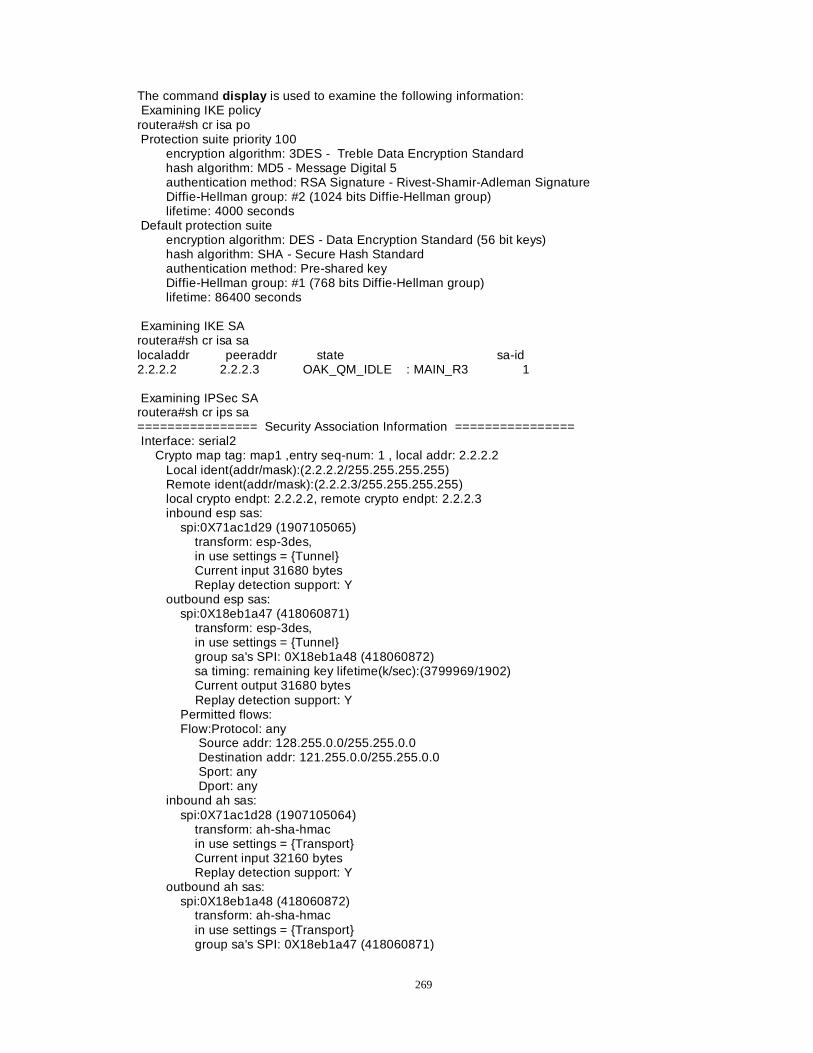
269
The command display is used to examine the following information: Examining IKE policy routera#sh cr isa po Protection suite priority 100 encryption algorithm: 3DES - Treble Data Encryption Standard hash algorithm: MD5 - Message Digital 5 authentication method: RSA Signature - Rivest-Shamir-Adleman Signature Diffie-Hellman group: #2 (1024 bits Diffie-Hellman group) lifetime: 4000 seconds Default protection suite encryption algorithm: DES - Data Encryption Standard (56 bit keys) hash algorithm: SHA - Secure Hash Standard authentication method: Pre-shared key Diffie-Hellman group: #1 (768 bits Diffie-Hellman group) lifetime: 86400 seconds Examining IKE SA routera#sh cr isa sa localaddr peeraddr state sa-id 2.2.2.2 2.2.2.3 OAK_QM_IDLE : MAIN_R3 1 Examining IPSec SA routera#sh cr ips sa ================ Security Association Information ================ Interface: serial2 Crypto map tag: map1 ,entry seq-num: 1 , local addr: 2.2.2.2 Local ident(addr/mask):(2.2.2.2/255.255.255.255) Remote ident(addr/mask):(2.2.2.3/255.255.255.255) local crypto endpt: 2.2.2.2, remote crypto endpt: 2.2.2.3 inbound esp sas: spi:0X71ac1d29 (1907105065) transform: esp-3des, in use settings = {Tunnel} Current input 31680 bytes Replay detection support: Y outbound esp sas: spi:0X18eb1a47 (418060871) transform: esp-3des, in use settings = {Tunnel} group sa's SPI: 0X18eb1a48 (418060872) sa timing: remaining key lifetime(k/sec):(3799969/1902) Current output 31680 bytes Replay detection support: Y Permitted flows: Flow:Protocol: any Source addr: 128.255.0.0/255.255.0.0 Destination addr: 121.255.0.0/255.255.0.0 Sport: any Dport: any inbound ah sas: spi:0X71ac1d28 (1907105064) transform: ah-sha-hmac in use settings = {Transport} Current input 32160 bytes Replay detection support: Y outbound ah sas: spi:0X18eb1a48 (418060872) transform: ah-sha-hmac in use settings = {Transport} group sa's SPI: 0X18eb1a47 (418060871)
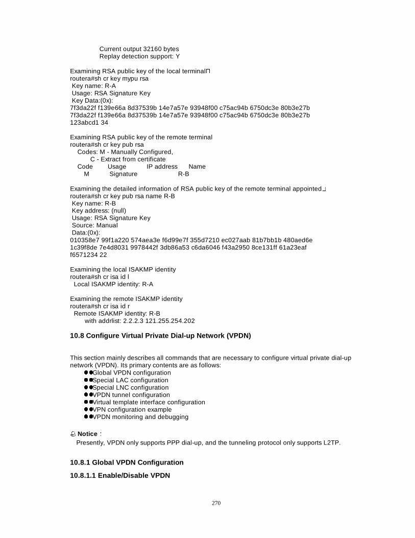
270
Current output 32160 bytes Replay detection support: Y Examining RSA public key of the local terminal� routera#sh cr key mypu rsa Key name: R-A Usage: RSA Signature Key Key Data:(0x): 7f3da22f f139e66a 8d37539b 14e7a57e 93948f00 c75ac94b 6750dc3e 80b3e27b 7f3da22f f139e66a 8d37539b 14e7a57e 93948f00 c75ac94b 6750dc3e 80b3e27b 123abcd1 34 Examining RSA public key of the remote terminal routera#sh cr key pub rsa Codes: M - Manually Configured, C - Extract from certificate Code Usage IP address Name
M Signature R-B Examining the detailed information of RSA public key of the remote terminal appointed� routera#sh cr key pub rsa name R-B Key name: R-B Key address: (null) Usage: RSA Signature Key Source: Manual Data:(0x): 010358e7 99f1a220 574aea3e f6d99e7f 355d7210 ec027aab 81b7bb1b 480aed6e 1c39f8de 7e4d8031 9978442f 3db86a53 c6da6046 f43a2950 8ce131ff 61a23eaf f6571234 22 Examining the local ISAKMP identity routera#sh cr isa id l Local ISAKMP identity: R-A Examining the remote ISAKMP identity routera#sh cr isa id r Remote ISAKMP identity: R-B with addrlist: 2.2.2.3 121.255.254.202 10.8 Configure Virtual Private Dial-up Network (VPDN)
This section mainly describes all commands that are necessary to configure virtual private dial-up network (VPDN). Its primary contents are as follows:
zzGlobal VPDN configuration zzSpecial LAC configuration zzSpecial LNC configuration zzVPDN tunnel configuration zzVirtual template interface configuration zzVPN configuration example zzVPDN monitoring and debugging
�� NoticeÛÛ Presently, VPDN only supports PPP dial-up, and the tunneling protocol only supports L2TP.
10.8.1 Global VPDN Configuration
10.8.1.1 Enable/Disable VPDN
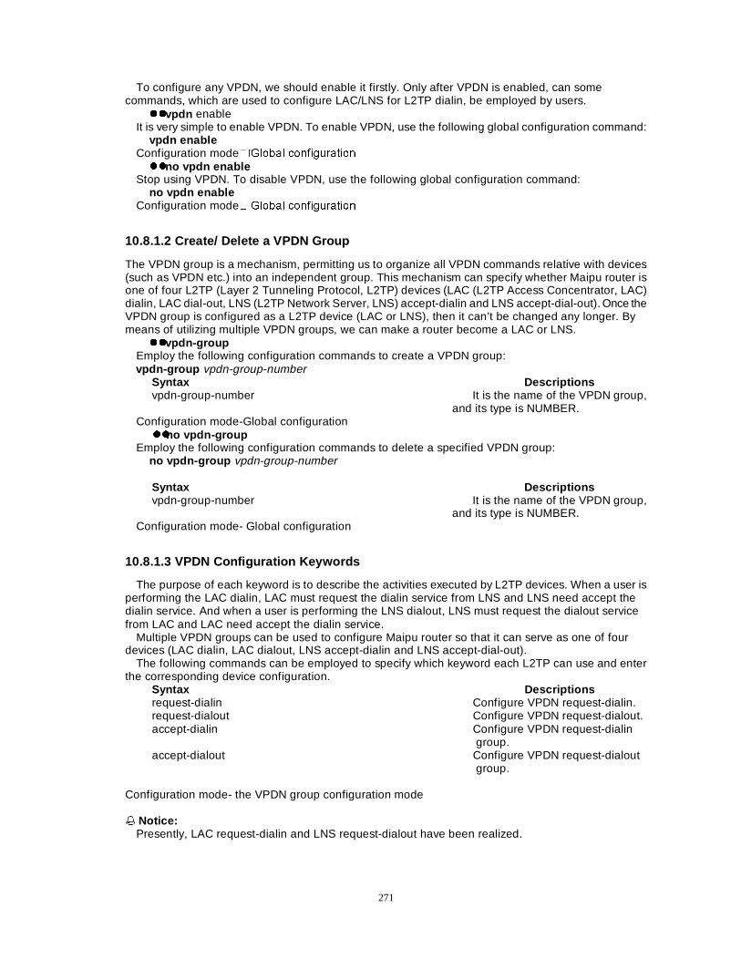
271
To configure any VPDN, we should enable it firstly. Only after VPDN is enabled, can some commands, which are used to configure LAC/LNS for L2TP dialin, be employed by users.
zzvpdn enable It is very simple to enable VPDN. To enable VPDN, use the following global configuration command:
vpdn enable Configuration mode��*OREDO FRQILJXUDWLRQ zzno vpdn enable
Stop using VPDN. To disable VPDN, use the following global configuration command: no vpdn enable
Configuration mode� *OREDO FRQILJXUDWLRQ
10.8.1.2 Create/ Delete a VPDN Group
The VPDN group is a mechanism, permitting us to organize all VPDN commands relative with devices (such as VPDN etc.) into an independent group. This mechanism can specify whether Maipu router is one of four L2TP (Layer 2 Tunneling Protocol, L2TP) devices (LAC (L2TP Access Concentrator, LAC) dialin, LAC dial-out, LNS (L2TP Network Server, LNS) accept-dialin and LNS accept-dial-out). Once the VPDN group is configured as a L2TP device (LAC or LNS), then it can’t be changed any longer. By means of utilizing multiple VPDN groups, we can make a router become a LAC or LNS.
zzvpdn-group Employ the following configuration commands to create a VPDN group: vpdn-group vpdn-group-number
Syntax Descriptions vpdn-group-number It is the name of the VPDN group,
and its type is NUMBER. Configuration mode-Global configuration zzno vpdn-group
Employ the following configuration commands to delete a specified VPDN group: no vpdn-group vpdn-group-number Syntax Descriptions vpdn-group-number It is the name of the VPDN group,
and its type is NUMBER. Configuration mode- Global configuration
10.8.1.3 VPDN Configuration Keywords
The purpose of each keyword is to describe the activities executed by L2TP devices. When a user is performing the LAC dialin, LAC must request the dialin service from LNS and LNS need accept the dialin service. And when a user is performing the LNS dialout, LNS must request the dialout service from LAC and LAC need accept the dialin service.
Multiple VPDN groups can be used to configure Maipu router so that it can serve as one of four devices (LAC dialin, LAC dialout, LNS accept-dialin and LNS accept-dial-out).
The following commands can be employed to specify which keyword each L2TP can use and enter the corresponding device configuration.
Syntax Descriptions request-dialin Configure VPDN request-dialin. request-dialout Configure VPDN request-dialout. accept-dialin Configure VPDN request-dialin
group. accept-dialout Configure VPDN request-dialout
group.
Configuration mode- the VPDN group configuration mode �� Notice:
Presently, LAC request-dialin and LNS request-dialout have been realized.
272
10.8.2 Special LAC configuration
Enter the special LAC configuration mode when the VPDN group selects the keyword request-dialin for the L2TP device.
10.8.2.1 Specify the IP Address of the corresponding LNS
To make LAC find LNS according to VPDN group configuration information, employ the following command to specify the IP address:
initiate-to ip ip-address Syntax Descriptions ip-address It is the IP address of LNS and its
type is regular IP address. Configuration mode-the LAC request-dialin configuration mode
10.8.2.2 Identify LAC
To establish a tunnel, LAC and LNS need be identified by each other. According to LAC identification, LNS can find the corresponding VPDN-GROUP from its configuration and send back its own identification so that LAC can apply the identification to the command show . For LAC, the identification, which LNS adopts during the course of establishing a tunnel, isn’t important, but LAC must correctly identified itself, or else, LNS has no way to find the VPDN group related with LAC. Employ the following command to configure the identification:
local name lac-host-name Syntax Descriptions lac-host-name It is the name LAC uses to identify himself to
LNS, and its type is STRING. Configuration mode-the LAC request-dialin configuration mode
10.8.2.3 Specify VPDN Protocol for a VPDN Group
After a VPDN-GROUP is created, the VPDN protocol need be specified for it. Presently, L2TP (Lay 2 transport protocol) is a practical protocol. Employ the following command to specify the protocol for a VPDN-GROUP: protocol vpdn-protocol
Syntax Descriptions vpdn-protocol The VPDN group employs the L2TP protocol.
Presently, only the protocol can be used. Configuration mode- the LAC request-dialin configuration mode
10.8.2.4 Specify a Method for LAC to Identify L2TP Users
When a user dials in a LAC, LAC needs a method to identify his domain name. The L2TP user can add one domain name to the username (for example, maipu.com is the domain name of [email protected]) so that the mapping between the user and LNS can be established. Employ the following command to configure the identification: domain domain-name
Syntax Descriptions domain-name It is the domain name employed to relate the
user with LNS, and its type is STRING. Configuration mode- the LAC request-dialin configuration mode
10.8.3 Special LNS Configuration
Enter the special LNS configuration mode when the VPDN group selects the keyword accept-dialin for the L2TP device.
273
10.8.3.1 Specify the Name to Identify LNS
To establish a tunnel, LAC and LNS need be identified by each other. According to LAC identification, LNS can find the corresponding VPDN-GROUP from its configuration and send back its own identification so that LAC can apply the identification to the command show . For LAC, the identification, which LNS adopts during the course of establishing a tunnel, isn’t important, but LAC must correctly identified itself, or else, LNS has no way to find the VPDN group related with LAC. Employ the following command to configure the identification: local name lns-host-name
Command Descriptions lns-host-name It is the name of LNS provides to LAC, and
its type is STRING. Configuration mode - the LNS accept-dialin configuration mode.
10.8.3.2 Specify the Name to identify LAC:
When LAC need establish a LNS tunnel, LAC sends its identification to LNS, then, LNS finds the corresponding VPDN group to perform the identification. Employ the following command to configure the identification of LAC: terminate-from hostname lac-host-name
Command Descriptions lac-host-name It is the name of LAC provides to LNS, and
its type is STRING. Configuration mode - the LNS accept-dialin configuration mode
10.8.3.3 Specify the Virtual Template Interface
TO stop the existing L2TP session, there must be an interface to stop the session. In fact, a L2TP packet is a PPP packet with an additional data header. Once the header is removed, the PPP packet can work. To make the PPP packet take effective, a virtual access interface that can understand the data of PPP packet head is dynamically established by a virtual template interface specified in VPDN-GROUP. Once a virtual template interface is specified, the virtual access interface should be generated and configured correctly so that it can understand the data of PPP packet. Employ the following command to specify which virtual template interface in VPDN-GROUP is used to create a virtual access interface in VPDN-GROUP during the course of session establishment:
virtual-template virtual-template-number Command Descriptions virtual-template-number Specify the virtual template number that is used
during the course of session establishment, and its range is from <1-25>.
Configuration mode - the LNS accept-dialin configuration mode
10.8.3.4 Specify the VPDN Protocol in a VPDN Group
After a VPDN-GROUP is created, the VPDN protocol to be used can be configured. Presently, only L2TP (Layer 2 Tunneling protocol) is the practical protocol that has been realized.
Employ the following command: protocol vpdn-protocol
Command Descriptions vpdn-protocol The VPDN group employs the L2TP protocol.
Presently, only the protocol can be used. Configuration mode - the LNS accept-dialin configuration mode
10.8.4 Configure VPDN Tunnel
10.8.4.1 Specify the Share Password of Tunnel
To establish a tunnel successfully, LAC and LNS must employ the share password to identify each other. The share password is configured in the corresponding VPDN-GROUP. You can employ the
274
following VPDN-GROUP configuration command to configure the share password that is employed during the course of identifying the tunnel. Use the following command to specify the share password: l2tp tunnel password password
Command Descriptions password It is the share password of a tunnel, and its type
is STRING. Configuration mode- the VPDN group configuration mode
10.8.4.2 Specify the receive-window-size of a tunnel
The receive-window-size of a tunnel can be specified through the following command in the VPDN group configuration: l2tp tunnel receive-window receive-window-size
Command Descriptions receive-window-size It is the receive-window-size, and its range is
<4-300>. Configuration mode- the VPDN group configuration mode
10.8.5 Configure the Virtual Template Interface
Once the virtual template interface number is specified on LNS, its corresponding virtual template need be created on LNS so that the virtual template interface can clone a virtual access interface dynamically during the course of establishing a tunnel and a session. A virtual template interface is a logical entity----the configuration of a serial-port, instead of being related with a physical interface. This logical entity can be dynamically applied on demand. A virtual access interface is a virtual interface, can be dynamically created and configured.
10.8.5.1 Creating a Virtual Template Interface
To create a virtual template interface and enter the interface configuration mode, use the following command in the global configuration mode:
interface virtual-template virtual-template-number Command Descriptions Virtual-template-number It is the virtual template number and its range
is <0-255>. Configuration mode- the Global configuration mode
10.8.5.2 Configure Other Relative Properties
A virtual template configuration can be added through PPP configuration commands, such as, encapsulation ppp�SSS DXWKHQWLFDWLRQ FKDS� DQG VR RQ� 7KH FRQFUHWH FRQILJXUDWLRQ FDQ UHIHU WR ³:$1
Protocol Configuration Manual”. Besides commands shutdown and dialer, all other commands that can be acceptable for the serial interface can also be used for the virtual template interface.
Configuration mode- the Interface configuration mode
��NoticeÛÛ Be sure to perform the configuration strictly according to the configuration manual.
10.8.6 Example of VPDN Configuration
The example is shown as the following figure:
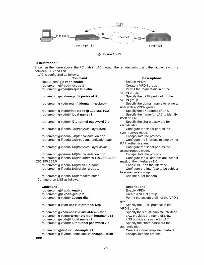
275
✆✆ Figure 10-15
Illustration ÛÛ Shown as the figure above, the PC dials in LAC through the remote dial-up, and the middle network is between LAC and LNS.
LAC is configured as follows: Command Descriptions
Router(config)# vpdn enable Enable VPDN. router(config)# vpdn-group 1 Create a VPDN group router(config-vpdn)#request-dialin Permit the request-dialin of the
VPDN group. router(config-vpdn-req-in)# protocol l2tp Specify the L2TP protocol for the
VPDN group. router(config-vpdn-req-in)#domain mp-2.com Specify the domain name to relate a
user with a VPDN group. router(config-vpdn)#initiate-to ip 192.168.10.2 Specify the IP address of LNS. router(config-vpdn)# local name r3 Specify the name for LAC to identify
itself on LNS. router(config-vpdn)# l2tp tunnel password 7 a Specify the share password for
identification. router(config-if-serial0/0)#physical-layer sync Configure the serial-port as the
synchronous mode. router(config-if-serial0/0)#encapsulation ppp Encapsulate the protocol. router(config-if-serial0/0)#ppp authentication pap Configure the interface to employ the
PAP authentication. router(config-if-serial1/0)#physical-layer async Configure the serial-port as the
asynchronous mode. router(config-if-serial1/0)#encapsulation ppp Encapsulate the protocol. router(config-if-serial1/0)#ip address 129.255.14.66
255.255.255.0 Configure the IP address and subnet
mask of the interface s1/0. router(config-if-serial1/0)#dialer in-band Enable DDR on the interface. router(config-if-serial1/0)#dialer-group 1 Configure the interface to be subject
to some dialer-group. router(config-if-serial1/0)# modem outer Use the outer modem.
Configure on LNS as follows: Command Descriptions router(config)# vpdn enable Enable VPDN. router(config)# vpdn-group 2 Create a VPDN group. router(config-vpdn)# accept-dialin Permit the accept-dialin of the VPDN
group. router(config-vpdn-acc-in)# protocol l2tp Specify the L2TP protocol in the
VPDN group. router(config-vpdn-acc-in)#virtual-template 1 Specify the virtual template interface. router(config-vpdn)#terminate-from hostname r3 LAC provides the name of LNS. router(config-vpdn)# local name r2 LNS provides its name to LAC. router(config-vpdn)# l2tp tunnel password 7 a Specify the share password for
authentication. router(config)#int virtual-template1 Create a virtual template interface. router(config-if-virtual-template1)# encapsulation
ppp Encapsulate the protocol.
PPP dial-up
ISP, L2TP LAC L2TP LNS
276
router(config-if-virtual-template1)# ppp authentication pap
Adopt the PAP as the authentication protocol.
router(config-if-virtual-template1)#ip unnumber loopback1
Enable the IP un-number on the interface.
router(config-if-virtual-template1)# peer default ip address pool vpdn-pool
Specify the opposite-end IP address of the interface.
router(config)# user [email protected] password 0 a
Configure the username and password for the dialin user.
router(config)# ip local pool vpdn-pool 172.16.20.10 172.16.20.100
Configure the address pool.
router(config-if-loopback1)# ip address 172.16.20.1 255.255.255.0
Configure the IP address of L1.
router(config-if-serial2/0)#physical-layer sync Configure the serial interface as the synchronous mode.
router(config-if-serial2/0)#clock rate 9600 Configure the clock. router(config-if-serial2/0)# encapsulation ppp Encapsulate the protocol. router(config-if-serial2/0)# ip address 192.168.10.2
255.255.255.0 Configure the IP address.
10.8.7 VPDN Monitoring and Debugging
zz show vpdn Display the configuration of Tunnel. �&RPPDQG PRGH�WKH SULYLOHJH XVHU PRGH� zzdebug l2tp data
Trace the information related with messages. no debug l2tp data �&RPPDQG PRGH�WKH SULYLOHJH XVHU PRGH� zzdebug l2tp event
Trace the sending and receiving of messages. no debug l2tp event �&RPPDQG PRGH�the privilege user mode. zzdebug l2tp detail
Trace the relative detail. no debug l2tp detail �&RPPDQG PRGH�WKH SULYLOHJH XVHU PRGH�
10.9 Configure GRE
GRE: short for Generic Routing Encapsulation��FDQ HQFDSVXODWH WKH GDWDJUDP RI VRPH QHWZRUN OD\HU
protocols (for example, IP) so that the encapsulated datagram can be transported over other network layer protocols (for example, IP). GRE adopts a tunnel technology between protocol layers. Tunnel is a virtual point-point interface that provides one channel over which the encapsulated datagram can be transported and encapsulates/decapsulates the datagram on both sides of the Tunnel interface.
Main contents of this section are described as follows: zzRelative command to configure GRE; zzExample of GRE configuration; zzGRE checking and debugging
10.9.1 Relative Commands to Configure GRE
zzinterface tunnel Use the Description following command to create a virtual Tunnel interface and enter the tunnel
configuration mode. The form no of the command is used to delete a specified tunnel. interface tunnel tunnel-number no interface tunnel tunnel-number
Syntax Descriptions tunnel-number Specify the tunnel-number, and its
range is 0-65535.
277
Default-No Tunnel interface is created. Command Mode-the Global configuration mode
zztunnel checksum Configure two sides of the tunnel to perform the checksum verification so as to check the correctness
of messages. The form no of the command is used to disable the checksum checking of the Tunnel interface.
tunnel checksum no tunnel checksum Default-Perform no checksum verification. Command-the Tunnel interface configuration mode.
NoticeÛÛ Different verification can be configured on two sides of the Tunnel interface, which has no effect on
its connectivity. zztunnel destination Configure the IP address of the opposite end of the Tunnel interface. The form no of the command is
used to delete the IP address of the opposite end of the Tunnel interface. tunnel destination ip-address no tunnel destination ip-address Syntax Descriptions ip-address Specify that the opposite end employs the IP address
of the factual physical port of the Tunnel interface. Default-Specify no IP address of the opposite end of the Tunnel interface. Command mode-the Tunnel interface configuration mode.
NoteÛÛ 1) Ip-address must be consistent with the physical port of the opposite end and assure the port is
reachable. 2) The destination address of local Tunnel interface must keep consistent with the source address of
the opposite-end Tunnel interface. zztunnel key Specify the identification key-number of the tunnel. And the form no of the command is used to
cancel the identification key of the tunnel. tunnel key key-number no tunnel key key-number
Syntax Descriptions key-number Specify the identification key-number of the tunnel.
And its value range is 0-4294967295. Default-Specify no identification key-number of the tunnel. Command mode-the Tunnel interface configuration mode.
NoteÛÛ Key-numbers of both sides of the tunnel must be consistent. zztunnel sequence-datagrams Configure two sides of the tunnel to verify the sequence-number of datagrams. This configuration can
be used to discard disordered datagrams. The form no of the command is employed to disable the verification of the sequence-number of datagrams.
tunnel sequence-datagrams no tunnel sequence-datagrams Default-Don’t verify the sequence-number of datagrams. Command Mode-the Tunnel interface configuration mode.
NoteÛÛ Different verification can be configured on the tunnel interface, without any effect on its connectivity.
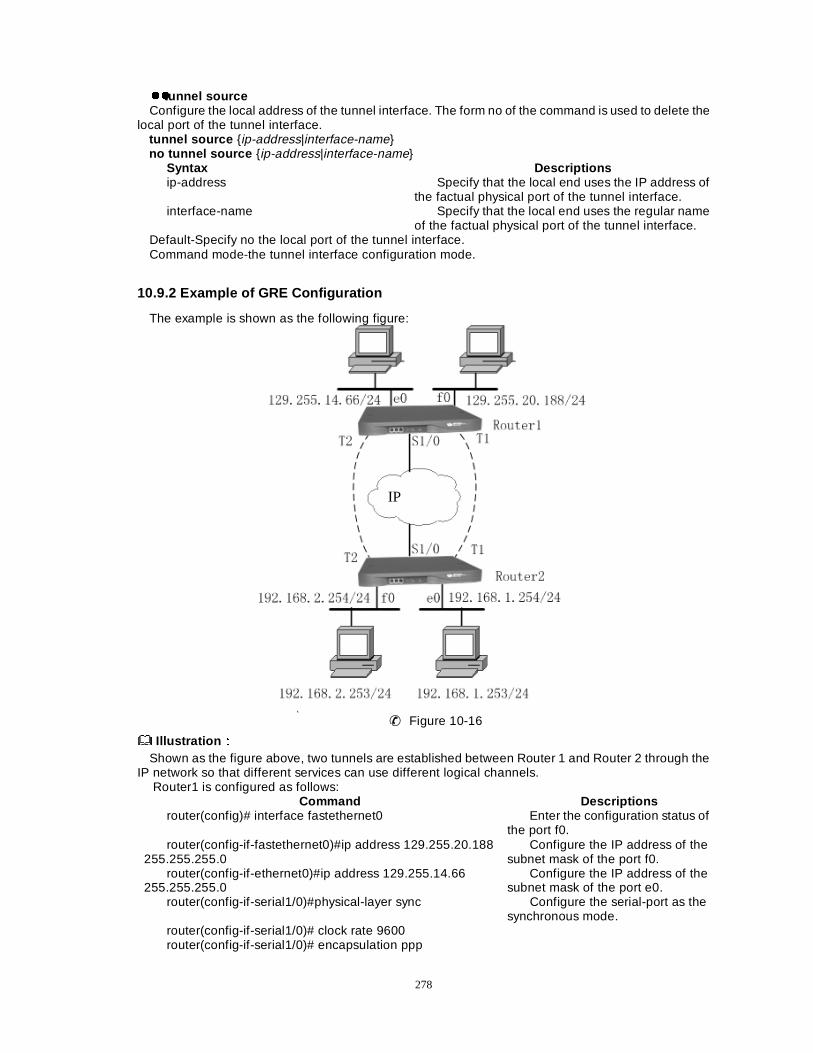
278
zztunnel source Configure the local address of the tunnel interface. The form no of the command is used to delete the
local port of the tunnel interface. tunnel source {ip-address|interface-name} no tunnel source {ip-address|interface-name}
Syntax Descriptions ip-address Specify that the local end uses the IP address of
the factual physical port of the tunnel interface. interface-name Specify that the local end uses the regular name
of the factual physical port of the tunnel interface. Default-Specify no the local port of the tunnel interface. Command mode-the tunnel interface configuration mode.
10.9.2 Example of GRE Configuration
The example is shown as the following figure:
✆✆ Figure 10-16
Illustration ÛÛ Shown as the figure above, two tunnels are established between Router 1 and Router 2 through the
IP network so that different services can use different logical channels. Router1 is configured as follows:
Command Descriptions router(config)# interface fastethernet0 Enter the configuration status of
the port f0. router(config-if-fastethernet0)#ip address 129.255.20.188
255.255.255.0 Configure the IP address of the
subnet mask of the port f0. router(config-if-ethernet0)#ip address 129.255.14.66
255.255.255.0 Configure the IP address of the
subnet mask of the port e0. router(config-if-serial1/0)#physical-layer sync Configure the serial-port as the
synchronous mode. router(config-if-serial1/0)# clock rate 9600 router(config-if-serial1/0)# encapsulation ppp
IP

279
router(config-if-serial1/0)# ip address 20.1.1.1 255.255.255.0
Configure the IP address of the subnet mask of the port s1/0.
router(config-if-serial1/0)# ip address 20.1.2.1 255.255.255.0 secondary
Distribute a secondary address to the s1/0.
router(config-if-serial1/0)#intface tunnel1 router(config-if-tunnel1)# ip address 1.1.1.1
255.255.255.0 Configure the IP address of the
subnet mask of the tunnel1. router(config-if-tunnel1)#tunnel source 20.1.1.1 The local end uses the IP
address of the factual physical port of the tunnel interface.
router(config-if-tunnel1)#tunnel destination 30.1.1.2 The opposite end uses the IP address of the factual physical port of the tunnel interface.
router(config-if-tunnel1)#ip route peer-address 1.1.1.2 Specify the IP address of opposite end of the tunnel 1 in the dynamic route.
router(config-if-tunnel1)#intface tunnel2 router(config-if-tunnel2)#ip address 2.1.1.1 255.255.255.0 Configure the IP address of the
subnet mask of the port tunnel2. router(config-if-tunnel2)# tunnel source 20.1.2.1 The local end uses the IP
address of the factual physical port of the tunnel interface.
router(config-if-tunnel2)#tunnel destination 30.1.2.2 The opposite end uses the IP address of the factual physical port of the tunnel interface.
router(config-if-tunnel2)#ip route peer-address 2.1.1.2 Specify the IP address of opposite end of the tunnel 2 in the dynamic route.
router(config-ospf)#network 129.255.20.0 0.0.0.255 area 0 Configure the relative dynamic routing protocol.
router(config-ospf)#network 1.1.1.0 0.0.0.255 area 0 router(config-ospf)#network 2.1.1.0 0.0.0.255 area 1 router(config-ospf)#network 129.255.14.0 0.0.0.255 area 1 router(config)# ip route 30.1.1.0 255.255.255.0 20.1.1.2 Configure the relative static
routing protocol for the middle channel.
router(config)# ip route.30.1.2.0 255.255.255.0 20.1.2.2 Route2 is configured as follows:
Command Descriptions router(config)# interface fastethernet0 Enter the configuration status of the
port f0. router(config-if-fastethernet0)#ip address 192.168.2.254 255.255.255.0 Configure the IP address of
the subnet mask of the port f0.
router(config-if-ethernet0)#ip address 192.168.1.254 255.255.255.0 Configure the IP address of the subnet mask of the port e0.
router(config-if-serial1/0)# physical-layer sync Configure the serial-port as the synchronous mode.
router(config-if-serial1/0)# clock rate 9600 Configure the clock router(config-if-serial1/0)# encapsulation ppp Encapsulate the protocol router(config-if-serial1/0)# ip address 30.1.1.2 255.255.255.0 Configure the IP address of the
subnet mask of the port s1/0. router(config-if-serial1/0)# ip address 30.1.2.2 255.255.255.0 secondary Distribute a secondary
address to the s1/0. router(config-if-serial1/0)#intface tunnel1 router(config-if-tunnel1)# ip address 1.1.1.2 255.255.255.0 Configure the IP address of the
subnet mask of the tunnel1. router(config-if-tunnel1)#tunnel source 30.1.1.2 The local end uses the IP address of
280
the factual physical port of the tunnel interface.
router(config-if-tunnel1)#tunnel destination 20.1.1.1 The opposite end uses the IP address of the factual physical port of the tunnel interface.
router(config-if-tunnel1)#ip route peer-address 1.1.1.1 Specify the IP address of opposite end of the tunnel 1 in the dynamic route.
router(config-if-tunnel1)#intface tunnel2 router(config-if-tunnel2)#ip address 2.1.1.2 255.255.255.0 Configure the IP address of the
subnet mask of the port tunnel2.
router(config-if-tunnel2)#tunnel source 30.1.2.2 The local end uses the IP address of the factual physical port of the tunnel interface.
router(config-if-tunnel2)#tunnel destination 20.1.2.1 The opposite-end uses the IP address of the factual physical port of the tunnel interface.
router(config-if-tunnel2)#ip route peer-address 2.1.1.1 Specify the IP address of opposite end of the tunnel 2 in the dynamic route.
router(config-ospf)#network 192.168.1.0 0.0.0.255 area 0 Configure the relative dynamic routing protocol.
router(config-ospf)#network 1.1.1.0 0.0.0.255 area 0 router(config-ospf)# network 2.1.1.0 0.0.0.255 area 1 router(config-ospf)# network 192.168.2.0 0.0.0.255 area 1
router(config)#ip route 20.1.1.0 255.255.255.0 30.1.1.1 Configure the relative static route of the middle physical line.
router(config)# ip route 20.1.2.0 255.255.255.0 30.1.2.1 �� Notice: zz This is an application of the network isolation. And usually, it can work in with NIA/URA to
realize the isolation of user authentication.
10.9.3 GRE Checking and Debugging
zzshow tunnel-chain zz Display all Tunnel configurations. show tunnel-chain
zz LCommand modeMthe privilege user mode. zzshow gre statistics zz Display the gre statistics. show gre statistics
zz LCommand modeMthe privilege user mode. zzdebug tunnel data zz Enable the information debugging switch. The form no of the command is used to disable the
tunnel debugging switch. debug tunnel data no debug tunnel data zz LCommand modeMthe privilege user mode.
10.10 Configuration of Digital Certificate
In this section, we mainly narrate the terminologies, principles and characteristics of Digital Certificate as well as relative debugging commands and information.

281
Main contents are as followsÖ zz Terminologies involved in Digital Certificate; zz Introduction to Digital Certificate; zz Debugging commands and debugging information.
10.10.1 Parsing of Terminologies Relative with Digital Certificate
Asymmetric Cryptography: In Asymmetric Cryptography systems, there exists a certain relation between cipher key and decryption key, but they are entirely different, that one of them can be made public and never mind that someone can calculate or deduce the other. So, the asymmetric key is also called public key. Certificate: A certificate, as a special form of digital marking sentence, provides a mechanism to confirm the relationship between public key and entities that hold private key, signed and delivered by the certificate authority (holding other pair of private key and public key). Generally, a certificate also contains other information relating to subject public key, such as the identification information of an entity that has the right to use private key. So when a certificate is delivered, the certificate authority should prove the correctness of the binding between the subject public key and the subject identification information. CA----Certification Authority- Simply speaking, it is an entity or service that delivers certificates. CA acts as the role of a guarantor that is bound between the subject public key and the subject identification information that are all included in the delivered certificate. IKE needs the support from CA Certification Center when negotiating by certificate.
10.10.2 Introduction to digital certificate
Both PKI and digital certificate technology bind the identification of individual or entity with a public key, and certificates are delivered uniformly by a certification delivery organization to ensure the validity and security of the certificate entity. In IPSec, the certificate authentication mode adopted by IKE can provide the following benefits:
1) To avoid the complications of manual configuration of IKE pre-share key or RSA key; 2) To increase the security of IKE negotiation; 3) To prevent the security problems as a result of the leak of cipher key through Certificate
Revocation List; 4) To achieve the restriction of validity period and prevention of the overdue usage of key; 5) To refresh certificates automatically; 6) To achieve the unified control of trusted domain by certificates; 7) To backup and restore keys; 8) To locate the person responsible easily when leak of key or unauthorized access arises.
10.10.3 Configuration of Certificate
10.10.3.1 Configure a CA Trusted Point and Set Trust Policy
A CA trusted point represents a set of CA trusted domains, by which one can set local certificate trust policy and management policies. Every CA trusted point’s configuration parameters and configuration policies include:
1) The URL address of a certificate Server 2) The CRL verification policies
3) The CRL automatic update policies 4) The CRL default update period 5) The time verification policies
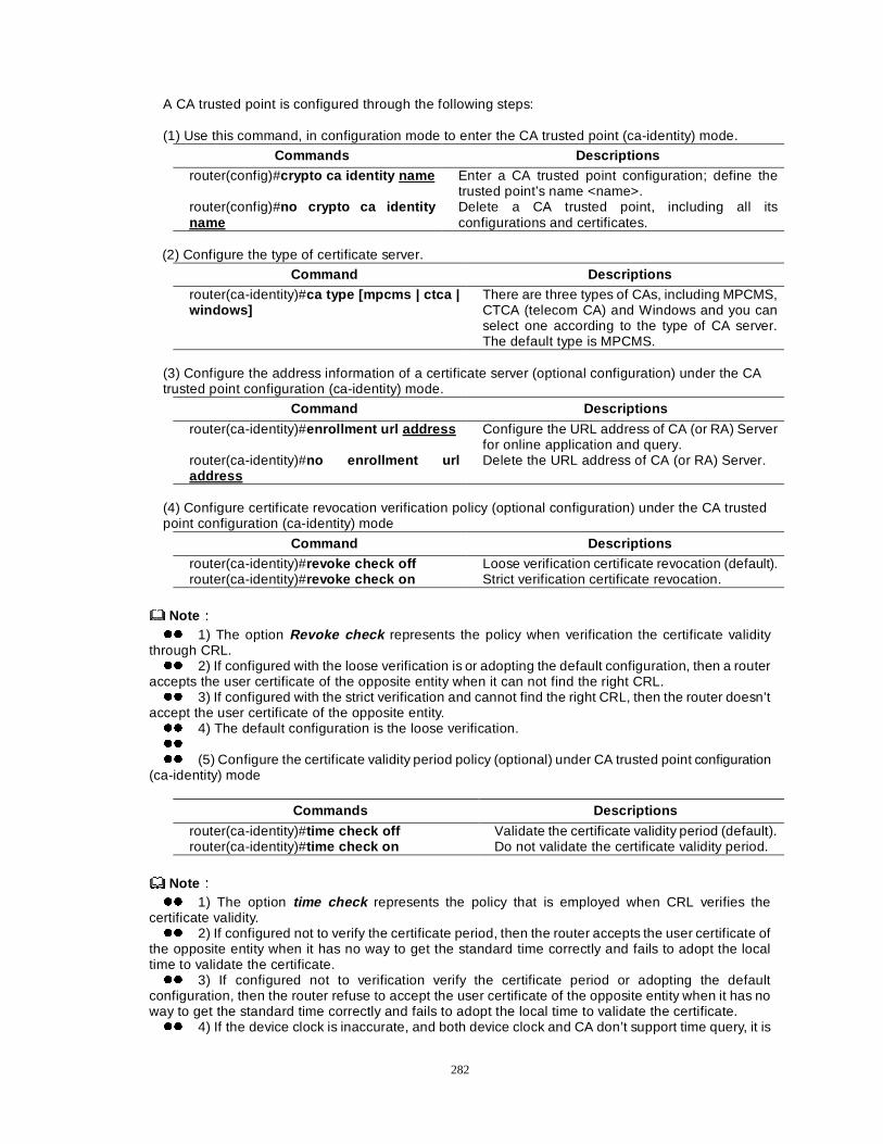
282
A CA trusted point is configured through the following steps: (1) Use this command, in configuration mode to enter the CA trusted point (ca-identity) mode.
Commands Descriptions router(config)#crypto ca identity name Enter a CA trusted point configuration; define the
trusted point’s name <name>. router(config)#no crypto ca identity name
Delete a CA trusted point, including all its configurations and certificates.
(2) Configure the type of certificate server.
Command Descriptions router(ca-identity)#ca type [mpcms | ctca | windows]
There are three types of CAs, including MPCMS, CTCA (telecom CA) and Windows and you can select one according to the type of CA server. The default type is MPCMS.
(3) Configure the address information of a certificate server (optional configuration) under the CA trusted point configuration (ca-identity) mode.
Command Descriptions
router(ca-identity)#enrollment url address Configure the URL address of CA (or RA) Server for online application and query.
router(ca-identity)#no enrollment url address
Delete the URL address of CA (or RA) Server.
(4) Configure certificate revocation verification policy (optional configuration) under the CA trusted point configuration (ca-identity) mode
Command Descriptions router(ca-identity)#revoke check off Loose verification certificate revocation (default). router(ca-identity)#revoke check on Strict verification certificate revocation.
NoteÛÛ zz 1) The option Revoke check represents the policy when verification the certificate validity
through CRL. zz 2) If configured with the loose verification is or adopting the default configuration, then a router
accepts the user certificate of the opposite entity when it can not find the right CRL. zz 3) If configured with the strict verification and cannot find the right CRL, then the router doesn’t
accept the user certificate of the opposite entity. zz 4) The default configuration is the loose verification. zz zz (5) Configure the certificate validity period policy (optional) under CA trusted point configuration
(ca-identity) mode
Commands Descriptions
router(ca-identity)#time check off Validate the certificate validity period (default). router(ca-identity)#time check on Do not validate the certificate validity period.
NoteÛÛ zz 1) The option time check represents the policy that is employed when CRL verifies the
certificate validity. zz 2) If configured not to verify the certificate period, then the router accepts the user certificate of
the opposite entity when it has no way to get the standard time correctly and fails to adopt the local time to validate the certificate. zz 3) If configured not to verification verify the certificate period or adopting the default
configuration, then the router refuse to accept the user certificate of the opposite entity when it has no way to get the standard time correctly and fails to adopt the local time to validate the certificate. zz 4) If the device clock is inaccurate, and both device clock and CA don’t support time query, it is
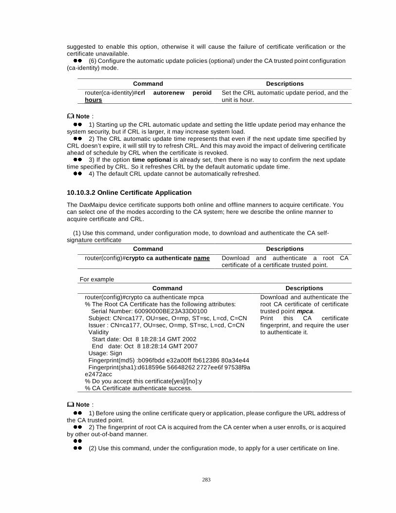
283
suggested to enable this option, otherwise it will cause the failure of certificate verification or the certificate unavailable. zz (6) Configure the automatic update policies (optional) under the CA trusted point configuration
(ca-identity) mode.
Command Descriptions router(ca-identity)#crl autorenew peroid hours
Set the CRL automatic update period, and the unit is hour.
NoteÛÛ zz 1) Starting up the CRL automatic update and setting the little update period may enhance the
system security, but if CRL is larger, it may increase system load. zz 2) The CRL automatic update time represents that even if the next update time specified by
CRL doesn’t expire, it will still try to refresh CRL. And this may avoid the impact of delivering certificate ahead of schedule by CRL when the certificate is revoked. zz 3) If the option time optional is already set, then there is no way to confirm the next update
time specified by CRL. So it refreshes CRL by the default automatic update time. zz 4) The default CRL update cannot be automatically refreshed.
10.10.3.2 Online Certificate Application
The DaxMaipu device certificate supports both online and offline manners to acquire certificate. You can select one of the modes according to the CA system; here we describe the online manner to acquire certificate and CRL.
(1) Use this command, under configuration mode, to download and authenticate the CA self-
signature certificate
Command Descriptions
router(config)#crypto ca authenticate name Download and authenticate a root CA certificate of a certificate trusted point.
For example
Command Descriptions router(config)#crypto ca authenticate mpca % The Root CA Certificate has the following attributes:
Serial Number: 60090000BE23A33D0100 Subject: CN=ca177, OU=sec, O=mp, ST=sc, L=cd, C=CN Issuer : CN=ca177, OU=sec, O=mp, ST=sc, L=cd, C=CN Validity Start date: Oct 8 18:28:14 GMT 2002 End date: Oct 8 18:28:14 GMT 2007 Usage: Sign Fingerprint(md5) :b096fbdd e32a00ff fb612386 80a34e44 Fingerprint(sha1):d618596e 56648262 2727ee6f 97538f9a e2472acc % Do you accept this certificate[yes]/[no]:y % CA Certificate authenticate success.
Download and authenticate the root CA certificate of certificate trusted point mpca . Print this CA certificate fingerprint, and require the user to authenticate it.
NoteÛÛ zz 1) Before using the online certificate query or application, please configure the URL address of
the CA trusted point. zz 2) The fingerprint of root CA is acquired from the CA center when a user enrolls, or is acquired
by other out-of-band manner. zz zz (2) Use this command, under the configuration mode, to apply for a user certificate on line.
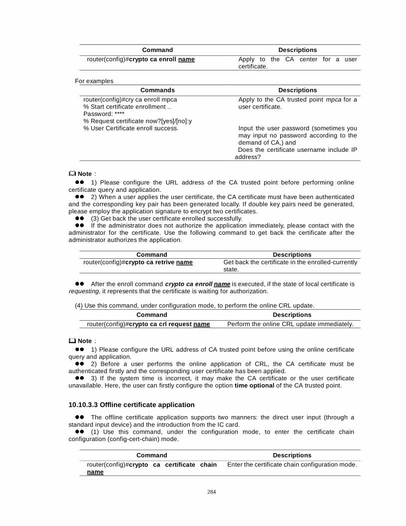
284
Command Descriptions router(config)#crypto ca enroll name Apply to the CA center for a user
certificate. For examples
Commands Descriptions
router(config)#cry ca enroll mpca % Start certificate enrollment .. Password: **** % Request certificate now?[yes]/[no]:y % User Certificate enroll success.
Apply to the CA trusted point mpca for a user certificate. Input the user password (sometimes you may input no password according to the demand of CA,) and Does the certificate username include IP
address?
NoteÛÛ zz 1) Please configure the URL address of the CA trusted point before performing online
certificate query and application. zz 2) When a user applies the user certificate, the CA certificate must have been authenticated
and the corresponding key pair has been generated locally. If double key pairs need be generated, please employ the application signature to encrypt two certificates. zz (3) Get back the user certificate enrolled successfully. zz If the administrator does not authorize the application immediately, please contact with the
administrator for the certificate. Use the following command to get back the certificate after the administrator authorizes the application.
Command Descriptions router(config)#crypto ca retrive name Get back the certificate in the enrolled-currently
state. zz After the enroll command crypto ca enroll name is executed, if the state of local certificate is
requesting, it represents that the certificate is waiting for authorization. (4) Use this command, under configuration mode, to perform the online CRL update.
Command Descriptions router(config)#crypto ca crl request name Perform the online CRL update immediately.
NoteÛÛ zz 1) Please configure the URL address of CA trusted point before using the online certificate
query and application. zz 2) Before a user performs the online application of CRL, the CA certificate must be
authenticated firstly and the corresponding user certificate has been applied. zz 3) If the system time is incorrect, it may make the CA certificate or the user certificate
unavailable. Here, the user can firstly configure the option time optional of the CA trusted point.
10.10.3.3 Offline certificate application
zz The offline certificate application supports two manners: the direct user input (through a standard input device) and the introduction from the IC card. zz (1) Use this command, under the configuration mode, to enter the certificate chain
configuration (config-cert-chain) mode.
Command Descriptions router(config)#crypto ca certificate chain name
Enter the certificate chain configuration mode.
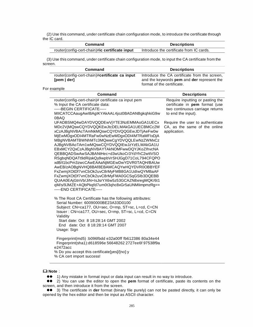
285
(2) Use this command, under certificate chain configuration mode, to introduce the certificate through
the IC card.
Command Descriptions router(config-cert-chain)#ic certificate input Introduce the certificate from IC cards.
(3) Use this command, under certificate chain configuration mode, to input the CA certificate from the
screen.
Command Descriptions router(config-cert-chain)#certificate ca input [pem | der]
Introduce the CA certificate from the screen, and the keywords pem and der represent the format of the certificate.
For example
Command Descriptions router(config-cert-chain)# certificate ca input pem % Input the CA certificate data: -----BEGIN CERTIFICATE----- MIICATCCAaugAwIBAgIKYAkAAL4joz0BADANBgkqhkiG9w0BAQ UFADBSMQ4wDAYDVQQDEwVjYTE3NzEMMAoGA1UECxMDc2VjMQswCQYDVQQKEwJtcDELMAkGA1UECBMCc2MxCzAJBgNVBAcTAmNkMQswCQYDVQQGEwJDTjAeFw0wMjEwMDgxODI4MTRaFw0wNzEwMDgxODI4MTRaMFIxDjAMBgNVBAMTBWNhMTc3MQwwCgYDVQQLEwNzZWMxCzAJBgNVBAoTAm1wMQswCQYDVQQIEwJzYzELMAkGA1UEBxMCY2QxCzAJBgNVBAYTAkNOMFwwDQYJKoZIhvcNAQEBBQADSwAwSAJBANtHec+d3wUkoCr3YdYhC2wttVSORSgbqNDQATt9dRijskQy9wpbVrSHJGgD71CoL794CFQPOxdB/t1bcPm3zwcCAwEAAaNjMGEwDwYDVR0TAQH/BAUwAwEB/zAOBgNVHQ8BAf8EBAMCAQYwHQYDVR0OBBYEFFxZwmjXOtDf7vnCbOk2uvC8rMyFMB8GA1UdIwQYMBaAFFxZwmjXOtDf7vnCbOk2uvC8rMyFMA0GCSqGSIb3DQEBBQUAA0EAjGtnVb/JiN+IsJsrYX6w5z53GCAZN8xregMQK/6t1qM/s/9JMZE+AQbPkqfd7um0t3qhc8xGr5aUNMIimpmzRg== -----END CERTIFICATE----- % The Root CA Certificate has the following attributes: Serial Number: 60090000BE23A33D0100 Subject: CN=ca177, OU=sec, O=mp, ST=sc, L=cd, C=CN Issuer : CN=ca177, OU=sec, O=mp, ST=sc, L=cd, C=CN Validity Start date: Oct 8 18:28:14 GMT 2002 End date: Oct 8 18:28:14 GMT 2007 Usage: Sign Fingerprint(md5) :b096fbdd e32a00ff fb612386 80a34e44 Fingerprint(sha1):d618596e 56648262 2727ee6f 97538f9a e2472acc % Do you accept this certificate[yes]/[no]:y % CA cert import success!
Require inputting or pasting the certificate in pem format (use two continuous carriage returns to end the input).
Require the user to authenticate CA, as the same of the online application.
NoteÛÛ zz 1) Any mistake in format input or data input can result in no way to introduce. zz 2) You can use the editor to open the pem format of certificate, paste its contents on the
screen, and then introduce it from the screen. zz 3) The certificate in der format (binary file purely) can not be pasted directly, it can only be
opened by the hex editor and then be input as ASCII character.
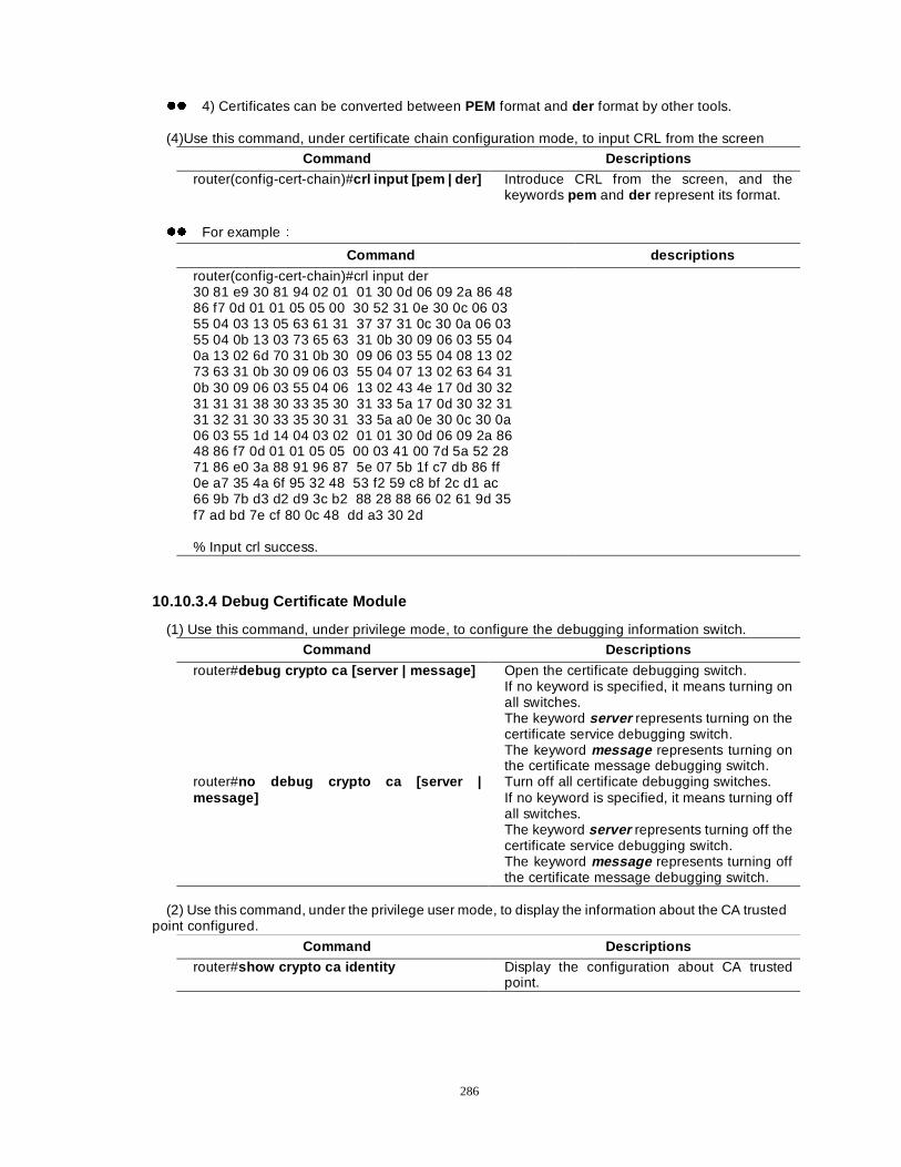
286
zz 4) Certificates can be converted between PEM format and der format by other tools. (4)Use this command, under certificate chain configuration mode, to input CRL from the screen
Command Descriptions
router(config-cert-chain)#crl input [pem | der] Introduce CRL from the screen, and the keywords pem and der represent its format.
zz For exampleÛ
Command descriptions
router(config-cert-chain)#crl input der 30 81 e9 30 81 94 02 01 01 30 0d 06 09 2a 86 48 86 f7 0d 01 01 05 05 00 30 52 31 0e 30 0c 06 03 55 04 03 13 05 63 61 31 37 37 31 0c 30 0a 06 03 55 04 0b 13 03 73 65 63 31 0b 30 09 06 03 55 04 0a 13 02 6d 70 31 0b 30 09 06 03 55 04 08 13 02 73 63 31 0b 30 09 06 03 55 04 07 13 02 63 64 31 0b 30 09 06 03 55 04 06 13 02 43 4e 17 0d 30 32 31 31 31 38 30 33 35 30 31 33 5a 17 0d 30 32 31 31 32 31 30 33 35 30 31 33 5a a0 0e 30 0c 30 0a 06 03 55 1d 14 04 03 02 01 01 30 0d 06 09 2a 86 48 86 f7 0d 01 01 05 05 00 03 41 00 7d 5a 52 28 71 86 e0 3a 88 91 96 87 5e 07 5b 1f c7 db 86 ff 0e a7 35 4a 6f 95 32 48 53 f2 59 c8 bf 2c d1 ac 66 9b 7b d3 d2 d9 3c b2 88 28 88 66 02 61 9d 35 f7 ad bd 7e cf 80 0c 48 dd a3 30 2d % Input crl success.
10.10.3.4 Debug Certificate Module
(1) Use this command, under privilege mode, to configure the debugging information switch.
Command Descriptions
router#debug crypto ca [server | message] Open the certificate debugging switch. If no keyword is specified, it means turning on all switches. The keyword server represents turning on the certificate service debugging switch. The keyword message represents turning on the certificate message debugging switch.
router#no debug crypto ca [server | message]
Turn off all certificate debugging switches. If no keyword is specified, it means turning off all switches. The keyword server represents turning off the certificate service debugging switch. The keyword message represents turning off the certificate message debugging switch.
(2) Use this command, under the privilege user mode, to display the information about the CA trusted
point configured.
Command Descriptions router#show crypto ca identity Display the configuration about CA trusted
point.
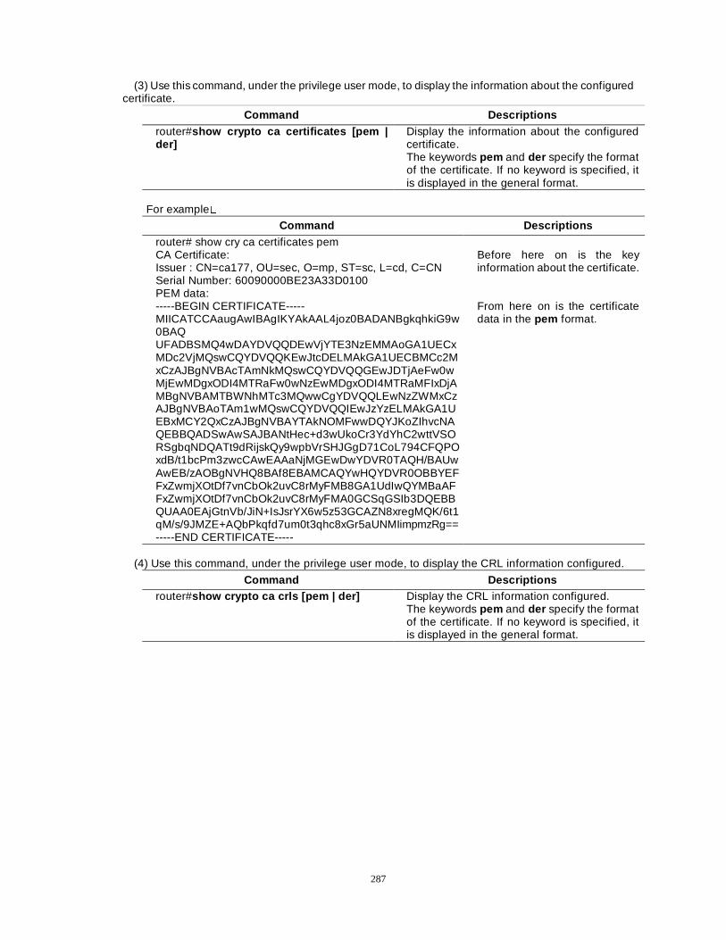
287
(3) Use this command, under the privilege user mode, to display the information about the configured certificate.
Command Descriptions router#show crypto ca certificates [pem | der]
Display the information about the configured certificate. The keywords pem and der specify the format of the certificate. If no keyword is specified, it is displayed in the general format.
For example�
Command Descriptions router# show cry ca certificates pem CA Certificate: Issuer : CN=ca177, OU=sec, O=mp, ST=sc, L=cd, C=CN Serial Number: 60090000BE23A33D0100 PEM data: -----BEGIN CERTIFICATE----- MIICATCCAaugAwIBAgIKYAkAAL4joz0BADANBgkqhkiG9w0BAQ UFADBSMQ4wDAYDVQQDEwVjYTE3NzEMMAoGA1UECxMDc2VjMQswCQYDVQQKEwJtcDELMAkGA1UECBMCc2MxCzAJBgNVBAcTAmNkMQswCQYDVQQGEwJDTjAeFw0wMjEwMDgxODI4MTRaFw0wNzEwMDgxODI4MTRaMFIxDjAMBgNVBAMTBWNhMTc3MQwwCgYDVQQLEwNzZWMxCzAJBgNVBAoTAm1wMQswCQYDVQQIEwJzYzELMAkGA1UEBxMCY2QxCzAJBgNVBAYTAkNOMFwwDQYJKoZIhvcNAQEBBQADSwAwSAJBANtHec+d3wUkoCr3YdYhC2wttVSORSgbqNDQATt9dRijskQy9wpbVrSHJGgD71CoL794CFQPOxdB/t1bcPm3zwcCAwEAAaNjMGEwDwYDVR0TAQH/BAUwAwEB/zAOBgNVHQ8BAf8EBAMCAQYwHQYDVR0OBBYEFFxZwmjXOtDf7vnCbOk2uvC8rMyFMB8GA1UdIwQYMBaAFFxZwmjXOtDf7vnCbOk2uvC8rMyFMA0GCSqGSIb3DQEBBQUAA0EAjGtnVb/JiN+IsJsrYX6w5z53GCAZN8xregMQK/6t1qM/s/9JMZE+AQbPkqfd7um0t3qhc8xGr5aUNMIimpmzRg== -----END CERTIFICATE-----
Before here on is the key information about the certificate. From here on is the certificate data in the pem format.
(4) Use this command, under the privilege user mode, to display the CRL information configured.
Command Descriptions router#show crypto ca crls [pem | der] Display the CRL information configured.
The keywords pem and der specify the format of the certificate. If no keyword is specified, it is displayed in the general format.
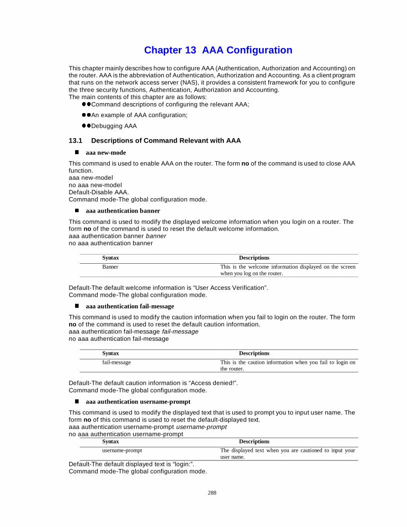
288
Chapter 13 AAA Configuration This chapter mainly describes how to configure AAA (Authentication, Authorization and Accounting) on the router. AAA is the abbreviation of Authentication, Authorization and Accounting. As a client program that runs on the network access server (NAS), it provides a consistent framework for you to configure the three security functions, Authentication, Authorization and Accounting. The main contents of this chapter are as follows:
zzCommand descriptions of configuring the relevant AAA;
zzAn example of AAA configuration;
zzDebugging AAA
13.1 Descriptions of Command Relevant with AAA
� aaa new-mode
This command is used to enable AAA on the router. The form no of the command is used to close AAA function. aaa new-model no aaa new-model Default-Disable AAA. Command mode-The global configuration mode.
� aaa authentication banner
This command is used to modify the displayed welcome information when you login on a router. The form no of the command is used to reset the default welcome information. aaa authentication banner banner no aaa authentication banner
Syntax Descriptions
Banner This is the welcome information displayed on the screen when you log on the router.
Default-The default welcome information is “User Access Verification”. Command mode-The global configuration mode.
� aaa authentication fail-message
This command is used to modify the caution information when you fail to login on the router. The form no of the command is used to reset the default caution information. aaa authentication fail-message fail-message no aaa authentication fail-message
Syntax Descriptions
fail-message This is the caution information when you fail to login on the router.
Default-The default caution information is “Access denied!”. Command mode-The global configuration mode.
� aaa authentication username-prompt
This command is used to modify the displayed text that is used to prompt you to input user name. The form no of this command is used to reset the default-displayed text. aaa authentication username-prompt username-prompt no aaa authentication username-prompt
Syntax Descriptions
username-prompt The displayed text when you are cautioned to input your user name.
Default-The default displayed text is “login:”. Command mode-The global configuration mode.
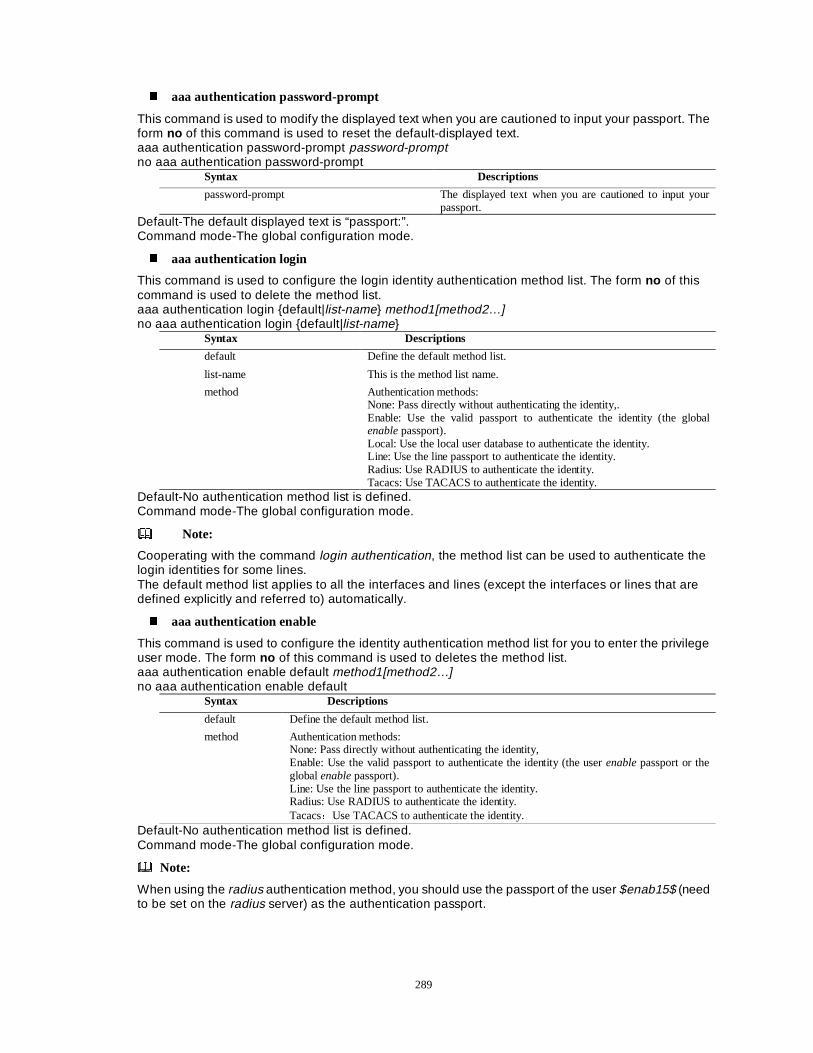
289
� aaa authentication password-prompt
This command is used to modify the displayed text when you are cautioned to input your passport. The form no of this command is used to reset the default-displayed text. aaa authentication password-prompt password-prompt no aaa authentication password-prompt
Syntax Descriptions
password-prompt The displayed text when you are cautioned to input your passport.
Default-The default displayed text is “passport:”. Command mode-The global configuration mode.
� aaa authentication login
This command is used to configure the login identity authentication method list. The form no of this command is used to delete the method list. aaa authentication login {default|list-name} method1[method2…] no aaa authentication login {default|list-name}
Syntax Descriptions
default Define the default method list.
list-name This is the method list name.
method Authentication methods: None: Pass directly without authenticating the identity,. Enable: Use the valid passport to authenticate the identity (the global enable passport). Local: Use the local user database to authenticate the identity. Line: Use the line passport to authenticate the identity. Radius: Use RADIUS to authenticate the identity. Tacacs: Use TACACS to authenticate the identity.
Default-No authentication method list is defined. Command mode-The global configuration mode.
Note:
Cooperating with the command login authentication, the method list can be used to authenticate the login identities for some lines. The default method list applies to all the interfaces and lines (except the interfaces or lines that are defined explicitly and referred to) automatically.
� aaa authentication enable
This command is used to configure the identity authentication method list for you to enter the privilege user mode. The form no of this command is used to deletes the method list. aaa authentication enable default method1[method2…] no aaa authentication enable default
Syntax Descriptions
default Define the default method list.
method Authentication methods: None: Pass directly without authenticating the identity, Enable: Use the valid passport to authenticate the identity (the user enable passport or the global enable passport). Line: Use the line passport to authenticate the identity. Radius: Use RADIUS to authenticate the identity. TacacsÖUse TACACS to authenticate the identity.
Default-No authentication method list is defined. Command mode-The global configuration mode.
Note:
When using the radius authentication method, you should use the passport of the user $enab15$ (need to be set on the radius server) as the authentication passport.
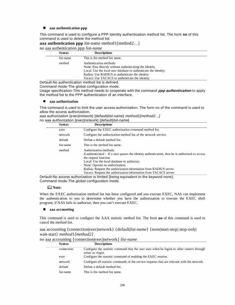
290
� aaa authentication ppp
This command is used to configure a PPP identity authentication method list. The form no of this command is used to delete the method list. aaa authentication ppp list-name method1[method2…] no aaa authentication ppp list-name
Syntax Descriptions
list-name This is the method list name.
method Authentication methods: None: Pass directly without authenticating the identity. Local: Use the local user database to authenticate the identity. Radius: Use RADIUS to authenticate the identity. Tacacs: Use TACACS to authenticate the identity.
Default-No authentication method list is defined. Command mode-The global configuration mode. Usage specification-This method needs to cooperate with the command ppp authentication to apply the method list to the PPP authentication of an interface.
� aaa authorization
This command is used to limit the user access authorization. The form no of the command is used to allow the access authorization. aaa authorization {exec|network} {default|list-name} method1[method2…] no aaa authorization {exec|network} {default|list-name}
Syntax Descriptions
exec Configure the EXEC authorization command method list.
network Configure the authorization method list of the network service.
default Define a default method list.
list-name This is the method list name.
method Authorization methods: if-authenticated : If a user passes the identity authentication, then he is authorized to access the request function. Local: Use the local database to authorize. None: Operate no authorization. Radius: Request the authorization information from RADIUS server. Tacacs: Request the authorization information from TACACS server.
Default-No access authorization is limited (being equivalent to the keyword none). Command mode-The global configuration mode.
Note:
When the EXEC authorization method list has been configured and you execute EXEC, NAS can implement the authentication to you to determine whether you have the authorization to execute the EXEC shell program; if NAS fails to authorize, then you can’t execute EXEC.
� aaa accounting
This command is used to configure the AAA statistic method list. The form no of this command is used to cancel the method list.
aaa accounting {connection|exec|network} {default|list-name} {none|start-stop| stop-only| wait-start} method1[method2] no aaa accounting {connection|exec|network} list-name
Syntax Descriptions
connection Configure the statistic command that the user uses when he logins to other routers through telnet or rlogin.
exec Configure the statistic command of enabling the EXEC session.
network Configure all statistic commands of the service requests that are relevant with the network.
default Define a default method list.
list-name This is the method list name.
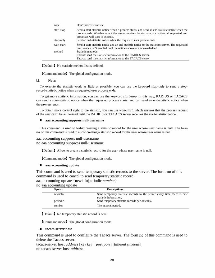
291
none Don’t process statistic.
start-stop Send a start-statistic notice when a process starts, and send an end-statistic notice when the process ends. Whether or not the server receives the start-statistic notice, all requested user processes will start to execute.
stop-only Send an end-statistic notice when the requested user process ends.
wait-start Send a start-statistic notice and an end-statistic notice to the statistics server. The requested user service isn’t enabled until the notices above are acknowledged.
method Statistic methods: Radius: send the statistic information to the RADIUS server. Tacacs: send the statistic information to the TACACS server.
LDefaultMNo statistic method list is defined.
LCommand modeMThe global configuration mode.
Note:
To execute the statistic work as little as possible, you can use the keyword stop-only to send a stop-record-statistic notice when a requested user process ends.
To get more statistic information, you can use the keyword start-stop. In this way, RADIUS or TACACS can send a start-statistic notice when the requested process starts, and can send an end-statistic notice when the process ends.
To obtain more control right to the statistic, you can use wait-start, which ensures that the process request of the user can’t be authorized until the RADIUS or TACACS server receives the start-statistic notice.
� aaa accounting suppress null-username
This command is used to forbid creating a statistic record for the user whose user name is null. The form no of this command is used to allow creating a statistic record for the user whose user name is null.
aaa accounting suppress null-username no aaa accounting suppress null-username
LDefaultMAllow to create a statistic record for the user whose user name is null.
LCommand modeMThe global configuration mode.
� aaa accounting update
This command is used to send temporary statistic records to the server. The form no of this command is used to cancel to send temporary statistic record. aaa accounting update {newinfo|periodic number} no aaa accounting update
Syntax Descriptions
newinfo Send temporary statistic records to the server every time there is new statistic information.
periodic Send temporary statistic records periodically.
number The interval period.
LDefaultMNo temporary statistic record is sent.
LCommand modeMThe global configuration mode.
� tacacs-server host
This command is used to configure the Tacacs server. The form no of this command is used to delete the Tacacs server. tacacs-server host address [key key] [port port] [timeout timeout] no tacacs-server host address
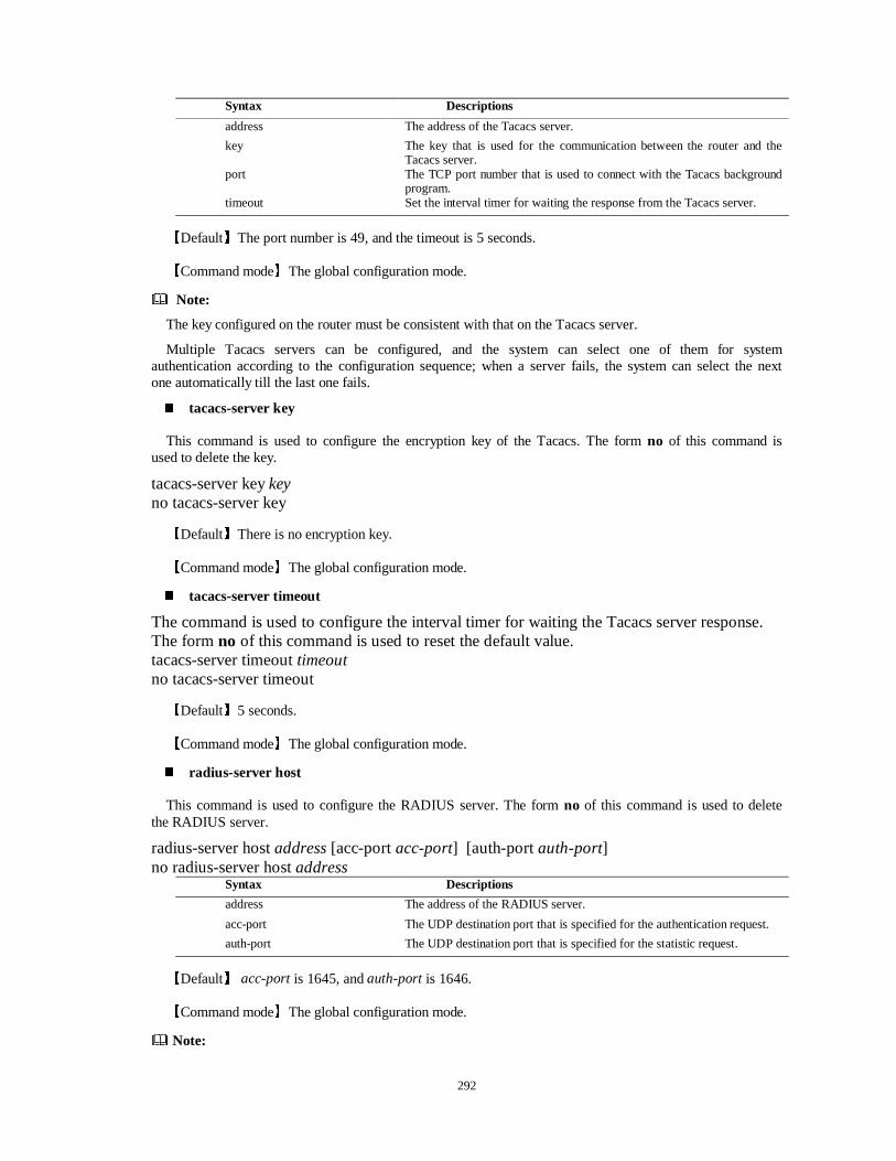
292
Syntax Descriptions
address The address of the Tacacs server.
key The key that is used for the communication between the router and the Tacacs server.
port The TCP port number that is used to connect with the Tacacs background program.
timeout Set the interval timer for waiting the response from the Tacacs server.
LDefaultMThe port number is 49, and the timeout is 5 seconds.
LCommand modeMThe global configuration mode.
Note:
The key configured on the router must be consistent with that on the Tacacs server.
Multiple Tacacs servers can be configured, and the system can select one of them for system authentication according to the configuration sequence; when a server fails, the system can select the next one automatically till the last one fails.
� tacacs-server key
This command is used to configure the encryption key of the Tacacs. The form no of this command is used to delete the key.
tacacs-server key key no tacacs-server key
LDefaultMThere is no encryption key.
LCommand modeMThe global configuration mode.
� tacacs-server timeout
The command is used to configure the interval timer for waiting the Tacacs server response. The form no of this command is used to reset the default value. tacacs-server timeout timeout no tacacs-server timeout
LDefaultM5 seconds.
LCommand modeMThe global configuration mode.
� radius-server host
This command is used to configure the RADIUS server. The form no of this command is used to delete the RADIUS server.
radius-server host address [acc-port acc-port] [auth-port auth-port] no radius-server host address
Syntax Descriptions
address The address of the RADIUS server.
acc-port The UDP destination port that is specified for the authentication request.
auth-port The UDP destination port that is specified for the statistic request.
LDefaultM acc-port is 1645, and auth-port is 1646.
LCommand modeMThe global configuration mode.
Note:
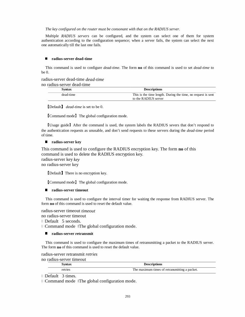
293
The key configured on the router must be consonant with that on the RADIUS server.
Multiple RADIUS servers can be configured, and the system can select one of them for system authentication according to the configuration sequence; when a server fails, the system can select the next one automatically till the last one fails.
� radius-server dead-time
This command is used to configure dead-time. The form no of this command is used to set dead-time to be 0.
radius-server dead-time dead-time no radius-server dead-time
Syntax Descriptions
dead-time This is the time length. During the time, no request is sent to the RADIUS server
LDefaultM dead-time is set to be 0.
LCommand modeMThe global configuration mode.
LUsage guideMAfter the command is used, the system labels the RADIUS severs that don’t respond to the authentication requests as unusable, and don’t send requests to these servers during the dead-time period of time.
� radius-server key
This command is used to configure the RADIUS encryption key. The form no of this command is used to delete the RADIUS encryption key. radius-server key key no radius-server key
LDefaultMThere is no encryption key.
LCommand modeMThe global configuration mode.
� radius-server timeout
This command is used to configure the interval timer for waiting the response from RADIUS server. The form no of this command is used to reset the default value.
radius-server timeout timeout no radius-server timeout �Default�5 seconds. �Command mode�The global configuration mode.
� radius-server retransmit
This command is used to configure the maximum times of retransmitting a packet to the RADIUS server. The form no of this command is used to reset the default value.
radius-server retransmit retries no radius-server timeout
Syntax Descriptions
retries The maximum times of retransmitting a packet.
�Default�3 times. �Command mode�The global configuration mode.
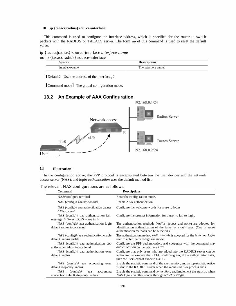
294
� ip {tacacs|radius} source-interface
This command is used to configure the interface address, which is specified for the router to switch packets with the RADIUS or TACACS server. The form no of this command is used to reset the default value.
ip {tacacs|radius} source-interface interface-name no ip {tacacs|radius} source-interface
Syntax Descriptions
interface-name The interface name.
LDefaultM Use the address of the interface f0.
LCommand modeMThe global configuration mode.
13.2 An Example of AAA Configuration
Illustration:
In the configuration above, the PPP protocol is encapsulated between the user devices and the network access server (NAS), and login authentication uses the default method list.
The relevant NAS configurations are as follows: Command Descriptions NAS#configure terminal Enter the configuration mode.
NAS (config)# aaa new-model Enable AAA authentication.
NAS (config)# aaa authentication banner ^ Welcome ^
Configure the welcome words for a use to login.
NAS (config)# aaa authentication fail-message ^ Sorry, Don’t come in ^
Configure the prompt information for a user to fail to login.
NAS (config)# aaa authentication login default radius tacacs none
The authentication methods (radius, tacacs and none) are adopted for identification authentication of the telnet or rlogin user. (One or more authentication methods can be selected.)
NAS (config)# aaa authentication enable default radius enable
The authentication method radius enable is adopted for the telnet or rlogin user to enter the privilege use mode.
NAS (config)# aaa authentication ppp auth-name radius tacacs local
Configure the PPP authentication, and cooperate with the command ppp authentication on the interface s1/0.
NAS (config)# aaa authorization exec default radius
Configure that only users who are added into the RADIUS server can be authorized to execute the EXEC shell program; if the authorization fails, then the users cannot execute EXEC.
NAS (config)# aaa accounting exec default stop-only radius
Enable the statistic command of the exec session, and a stop-statistic notice is sent to the RADIUS server when the requested user process ends.
NAS (config)# aaa accounting connection default stop-only radius
Enable the statistic command connection, and implement the statistic when NAS logins on other router through telnet or rlogin.
Network access
User
295
NAS (config)# aaa accounting network list stop-only radius
Enable the statistic command (list) that the PPP service requests. (Because the PPP protocol is encapsulated between the user devices and the NAS.)
NAS (config)# radius-server host 192.168.0.1
Configure the address of the RADIUS server.
NAS (config)# radius-server key maipu Configure the key of the RADIUS server, and the key must be the same as that of the NAS server on the RADIUS server.
NAS (config)# tacacs-server host 192.168.0.2 key mp
Configure the address and key of the TACACS server, and the key must be the same as that of the NAS server on the RADIUS server.
NAS (config)#interface s1/0 Enter the interface mode.
NAS(config-if-serial1/0)#ppp accounting list
Enable the PPP authentication statistic on the interface. Its name is list, which is the same as that following aaa accounting network.
Illustration:
In the configuration above, PPP protocol is encapsulated between user devices and the network access server, while login authentication uses the self-named method list named and applies this method list to the line.
The network access server is configured as follows:
Command Descriptions NAS#conifgure terminal Enter the configuration mode.
NAS (config)# aaa new-model Enable AAA authentication.
NAS (config)# aaa authentication banner ^ Welcome ^
Configure the welcome words for a use to login.
NAS (config)# aaa authentication fail-message ^ Sorry, Don’t come in ^
Configure the prompt information for a user to fail to login.
NAS (config)# aaa authentication login aa radius tacacs none
The authentication methods (radius, tacacs and none) are adopted for identification authentication of the telnet or rlogin user. And the self-defined of the method list is used.
NAS (config)# aaa authentication ppp list radius tacacs local
Configure the PPP authentication, and cooperate with the ppp authentication command (list) on the interface s1/0.
NAS (config)# aaa authorization exec default radius
Configure that only the users who are added into the RADIUS server can be authorized to execute the EXEC shell program; if the authorization fails, then the users cannot execute EXEC.
NAS (config)# aaa accounting exec default stop-only radius
Enable the statistic command of the exec session, and a stop-statistic notice is sent to the RADIUS server when the requested user process ends.
NAS (config)# aaa accounting connection default stop-only radius
Enable the statistic command connection, and implement the statistic when NAS logins on other router through telnet or rlogin.
NAS (config)# radius-server host 192.168.0.1
Configure the address of the RADIUS server.
NAS (config)# radius-server key maipu Configure the key of RADIUS server, and the key must be the same with that of NAS server on the RADIUS server.
NAS (config)# tacacs-server host 192.168.0.2 key mp
Configure the address and key of the TACACS server, and the key must be the same as that of NAS server on the RADIUS server.
NAS(config)#line vty 0 0 Only one user device is allowed to pass authentication; if multiple user devices are allowed to do so, then line vty 0 15.
NAS(config-line)#login authentication aa
Enable the key checking.
Note:
Please implement the configuration strictly according to the Configuration Manual.
During the course of adopting the configured method list to authenticate a user, only when the previous method doesn’t response can the router try the next method. If the identity authentication fails at any point of the period, namely, the security server or the local user name database response in the form of denying the user to access, then the identity authentication process will end and no other identity authentication method will be tried.
296
13.3 Checking and Debugging AAA � show accounting
This command is used to display the AAA statistic information. show accounting �Command mode�The privilege user mode.
� debug aaa authentication
This command is used to open the switch of AAA authentication debugging information. The form no of this command is used to close the switch. debug aaa authentication no debug aaa authentication �Command mode�The privilege user mode.
� debug aaa authorization
This command is used to open the switch of AAA authorization debugging information. The form no of this command is used to close the switch. debug aaa authorization no debug aaa authorization �Command mode�The privilege user mode.
� debug aaa accounting
This command is used to open the switch of AAA statistic debugging information. The form no of this command is used to close the switch. debug aaa accounting no debug aaa accounting �Command mode�The privilege user mode.
� debug tacacs
This command is used to open the switch of TACACS debugging information. The form no of this command is used to close the switch. debug tacacs no debug tacacs �Command mode�The privilege user mode.
� debug radius
This command is used to open the switch for RADIUS debugging information. The form no of this command is used to close the switch of RADIUS debugging information. debug radius [in-plain] no debug radius
Syntax Descriptions
in-plain Display the RADIUS packet information in the form of plaintext.
�Command mode�The privilege user mode.
297
Chapter 14 QoS Configuration
This chapter mainly describes the QoS technology of the IP network.
In the traditional IP network, all packets are treated equally, and each router adopts FIFO (first-in, first-out) policy to handle these packets, trying its best to send the packets to the destination. But it cannot provide with any guarantee for the packet transmission performances (such as the reliability and transmission delay etc.).
With the development of the IP network technologies, the traditional best-effort service cannot meet the new requirements to the QoS of the IP network, especially can’t distinguish various flows in the IP network at all. Therefore it cannot provide any application communication with priority or assurance and has no way to carry the communication that has some specific requirements to the network resources and service.
IP QoS applies itself to solving this problem. Through classification, labeling, communication speed management, resource allocation and congestion avoidance, it provides the priority service for the designated packets or data flow.
z The main contents of this section are as follows:
z 1) IntServ (Integrated Services):
z This involves the RSVP (Resource Reservation Protocol) section mainly.
z 2) DiffServ (Differentiated Services):
z According to technology features of the differentiated services, it is divided into three sections: the bandwidth management (for example, CAR etc.), the congestion management (mainly adopting the queuing mechanism) and the congestion avoidance (for example, RED and WRED etc.)
14.1 IntServ (Integrated Services) At present, Resource Reservation Protocol (RSVP), which delivers the QoS requests of applications
to transmission equipments (such as routers), is most used by the signaling transmission in the integrated services, and can provide two types of services:
· Guaranteed Service. It provides reliable bandwidth, delay limit to meet the requirements of applications.
· Controlled-Load Service. It provides the QoS guarantee, which is similar to that under the situation of no overload, for applications when the network is of overload. That is, it provides low delay and high-pass QoS guarantee when the network is of congestion, especially for applications with high requirements to the real-time, such as VOIP.
14.1.1 RSVP (Resource Reservation Protocol)
RSVP (Resource Reservation Protocol), as a standard signaling protocol, is used to ensure the point-to-point network bandwidth for the IP network. It adopts basic route allocation protocols to determine where to transmit the reserved request. When the route allocation changes paths to accommodate to the change of the topology structure, RSVP can make its reserved request accommodate to the new paths. This working mode doesn’t incommode other route allocation services. RSVP provides transparent operations through supporting no RSVP router nodes, cooperating with the current queuing mechanism instead of replacing it. RSVP applies for a specific queuing mechanism, but only a specific interface queuing mechanism can realize the reservation function.
� ip rsvp
ip rsvp bandwidth reservable-bandwidth largest-reservable-flow
ip rsvp {burst burst-factor}| {delay time-value}| {neighbor access-list}| signaling {conform | exceed} {dscp value | precedence value }| {udp-multicasts multicast-address}
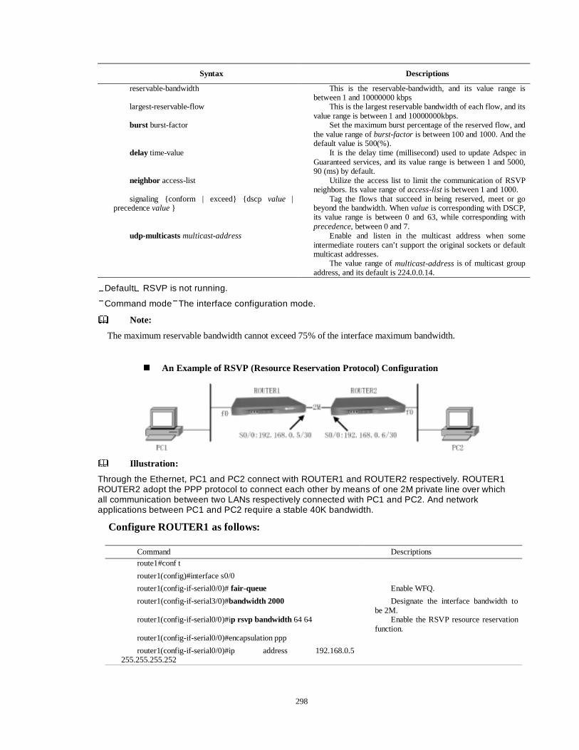
298
Syntax Descriptions
reservable-bandwidth This is the reservable-bandwidth, and its value range is between 1 and 10000000 kbps
largest-reservable-flow This is the largest reservable bandwidth of each flow, and its value range is between 1 and 10000000kbps.
burst burst-factor Set the maximum burst percentage of the reserved flow, and the value range of burst-factor is between 100 and 1000. And the default value is 500(%).
delay time-value It is the delay time (millisecond) used to update Adspec in Guaranteed services, and its value range is between 1 and 5000, 90 (ms) by default.
neighbor access-list Utilize the access list to limit the communication of RSVP neighbors. Its value range of access-list is between 1 and 1000.
signaling {conform | exceed} {dscp value | precedence value }
Tag the flows that succeed in being reserved, meet or go beyond the bandwidth. When value is corresponding with DSCP, its value range is between 0 and 63, while corresponding with precedence, between 0 and 7.
udp-multicasts multicast-address Enable and listen in the multicast address when some intermediate routers can’t support the original sockets or default multicast addresses.
The value range of multicast-address is of multicast group address, and its default is 224.0.0.14.
�Default� RSVP is not running.
�Command mode�The interface configuration mode.
Note:
The maximum reservable bandwidth cannot exceed 75% of the interface maximum bandwidth.
� An Example of RSVP (Resource Reservation Protocol) Configuration
Illustration:
Through the Ethernet, PC1 and PC2 connect with ROUTER1 and ROUTER2 respectively. ROUTER1 ROUTER2 adopt the PPP protocol to connect each other by means of one 2M private line over which all communication between two LANs respectively connected with PC1 and PC2. And network applications between PC1 and PC2 require a stable 40K bandwidth.
Configure ROUTER1 as follows:
Command Descriptions route1#conf t
router1(config)#interface s0/0
router1(config-if-serial0/0)# fair-queue Enable WFQ.
router1(config-if-serial3/0)#bandwidth 2000 Designate the interface bandwidth to be 2M.
router1(config-if-serial0/0)#ip rsvp bandwidth 64 64 Enable the RSVP resource reservation function.
router1(config-if-serial0/0)#encapsulation ppp
router1(config-if-serial0/0)#ip address 192.168.0.5 255.255.255.252
299
Configure ROUTER2 as follows:
� Configure RSVP Proxy
The proxy configuration is used to replace a node that cannot send RSVP messages to send RSVP messages, so that other nodes can realize the RSVP reservation through receiving the RSVP proxy message that the router creates.
ip rsvp
ip rsvp { sender | sender-host | reservation | reservation-host }
�Command mode�The global configuration mode.
Syntax Descriptions Sender Configure the PATH message proxy, of which the followed parameters are as
follows: the destination address reservable-flow, the resource address of reservable-flow, IP
protocol number of reservable-flow, the destination port of reservable-flow, the source port of reservable-flow, the previous hop address of PATH message, the supposed receiving interface of PATH message, the reservable-flow bandwidth, the reservable-flow burst-size.
sender-host Configure the PATH message proxy for the local application. And no receiving interface and previous hop addresses need be configured.
reservation Configure the RESV message proxy, of which the followed parameters are as follows:
the destination address a reservable-flow, the source address of a reservable-flow, IP protocol number of a reservable-flow, the destination port of a reservable-flow, the source port of a reservable-flow, the previous hop address of a RESV message, the supposed receiving interface of RESV message, the reservable share-style, the service that the reservable-flow applies for, the reservable-flow bandwidth, the reservable-flow burst-factor.
reservation-host Configure the RESV message proxy for the local application. No receiving interface and the previous hop address need be configured.
� Monitoring and Debugging RSVP (Resource Reservation Protocol)
show ip rsvp installed
This command is used to display the information about the flows that succeeds in RSVP reserving currently.
show ip rsvp installed
�Command mode�The privilege user mode.
show ip rsvp neighbour
This command is used to display the RSVP neighbor list that switches the RSVP signaling with the local router.
show ip rsvp neighbour
Command Descriptions Route2#conf t
Router2(config)#interface s0/0
Router2(config-if-serial0/0)# fair-queue Enable WFQ.
router2(config-if-serial3/0)#bandwidth 2000 Designate the interface bandwidth to be 2M.
Router2(config-if-serial0/0)#ip rsvp bandwidth 64 64 Enable the RSVP.
Router2(config-if-serial0/0)#encapsulation ppp
Router2(config-if-serial0/0)#ip address 192.168.0.6 255.255.255.252
300
�Command mode�The privilege user mode.
show ip rsvp sender
This command is used to display the list (PSB) of the PATH messages that the local router received.
show ip rsvp sender
�Command mode�The privilege user mode.
show ip rsvp reservation
This command is used to display the list (RSB) of the RESV messages that the local router received.
show ip rsvp reservation
�Command mode�The privilege user mode.
show ip rsvp blockade-state-block
This command is used to display the list (BSB) of the RESV messages that are denied by the previous hop and are received by the local router.
show ip rsvp blockade-state-block
�Command mode�The privilege user mode.
show ip rsvp timer
This command is used to display the list of the timers relevant with each RSVP in the local router.
show ip rsvp timer
�Command mode�The privilege user mode.
debug ip rsvp
This command is used to display the process that creates the RSVP reservation.
debug ip rsvp
�Command mode�The privilege user mode.
14.2 DiffServ (Differentiated Services) Differentiated service (Diffserv) needn’t maintain the status information for each kind of
communication and it can, according to the configured QoS mechanism, distinguish the QoS level of each message and provide services for this message. So, the mechanism that provides differentiated service is also called COS. There are many classification methods according to the priority of an IP message, source and destination address of an IP message, protocol type and message size etc. And the network classifies messages in terms of the information above for traffic management, shaping and queuing so as to implement bandwidth management, congestion management and congestion avoidance.
14.2.1 BwMg (Bandwidth Management)
14.2.1.1 CAR (Committed Access Rate)
CAR (Committed Access Rate) is a policy to manage bandwidth through ensuring the communication able to be transmitted within the designated rate parameter range (discarding the packets that go beyond the receivable range, or configuring their communication classes according to different policies).
� rate-limit
rate-limit { input | output } [access-group access-list-No] CIR conform burst exceed burst conform-action {actions [action val] } exceed-action { actions [action val] }
301
Syntax Descriptions {input | output} Designate whether this rule applies to the output packets or the input ones. access-list-No Use an access list and designate its number to match the packets. If this item
is default, then it matches all input/output packets on the interface. The value range is between 1 and 2000.
CIR Committed information rate, namely the given token rate, with a measure being bit per second, and its value range being between 8000 and100000000.
Conform burst Conform the allowed burst flow, namely the depth of the layer-1 token bucket (Bc) (its unit is by byte), and its value range is between 1500 and 50000000.
Exceed burst Exceed allowed burst flow, i.e. the depth of the layer-2 token bucket (Be) (its unit is by byte), and its value range is between 0 and 100000000.
actions [action val] The handling actions to a conform or exceed the burst flow, with the following options:
continue: Do nothing and make the packet continue to match the next rule. drop: Discard this packet. transmit: Transmit this packet. set-prec-continue: Set the priority of the packet to be action val and
continue. set-prec-transmit: Set the priority of the packet to be action val and transmit. set-dscp-continue: Set DSCP area of the packet to be action val and
continue. set-dscp-transmit: Set DSCP area of the packet to be action val and transmit.
{input | output} Designate whether this rule applies to the input packets or the output ones. access-list-No Use an access list and designate its number to match the packets. If this item
is default, then it matches all input/output packets on the interface. The value range is between 1 and 2000.
�Default� CAR is not executed.
�Command mode�The interface configuration mode.
Note:
1) Maipu series routers don’t support QoS Group, however, they add an action set-dscp-XXX to set DSCP area.
2) CAR of Maipu series routers can support rate-limitation on sub-interfaces. When these sub-interfaces are disabled by the command no, the CAR rules that exist on all sub-interfaces will be removed automatically instead of being reserved.
3) The CAR modules in Maipu series routers don’t support rapid-forwarding currently. If an interface is configured with any CAR rule, its rapid-forwarding function will be disabled automatically, without getting any caution from the system. This disabled rapid-forwarding function will be enabled automatically when all CAR rules on the interface are removed (if the command no ip route-cache is configured in this process, however, the rapid-forwarding function will not be enabled yet).
4) Seen from the point of the token bucket theory, the three parameters that are configured for CAR represent the given token rate, the depth of layer-1 token bucket (Bc) and the depth of layer-1 token bucket (Be) respectively (This is different from that of CISCO. The depth of CISCO layer-1 token bucket is corresponding with the depth sum of both layer-1 and layer-2 token buckets of Maipu series routers, but their functions are identical completely).
5) From the point of value, the recommended value of the conform-burst is equal to 1/320 of the conform bandwidth, and its minimum value is not less that 1/480 of conform bandwidth. If a value less than the minimum is configured, the system will give a caution.
6) The above recommended value and minimum have no measure, but the measure of conform bandwidth is bit per second while that of conform burst is byte. Namely, if the conform bandwidth is configured with the value 480000 (bit per second), then the minimum conform burst should be
480000 è 480 = 1000 (byte).
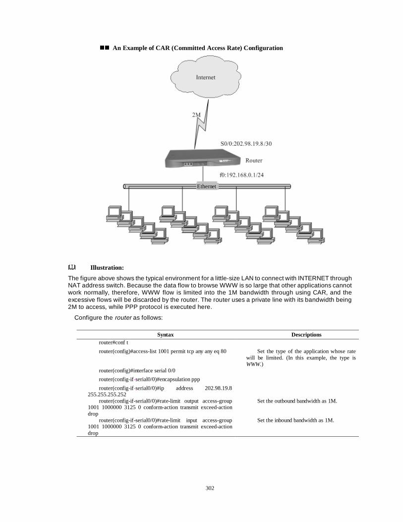
302
�� An Example of CAR (Committed Access Rate) Configuration
Illustration:
The figure above shows the typical environment for a little-size LAN to connect with INTERNET through NAT address switch. Because the data flow to browse WWW is so large that other applications cannot work normally, therefore, WWW flow is limited into the 1M bandwidth through using CAR, and the excessive flows will be discarded by the router. The router uses a private line with its bandwidth being 2M to access, while PPP protocol is executed here.
Configure the router as follows:
Syntax Descriptions router#conf t
router(config)#access-list 1001 permit tcp any any eq 80 Set the type of the application whose rate will be limited. (In this example, the type is WWW.)
router(config)#interface serial 0/0
router(config-if-serial0/0)#encapsulation ppp
router(config-if-serial0/0)#ip address 202.98.19.8 255.255.255.252
router(config-if-serial0/0)#rate-limit output access-group 1001 1000000 3125 0 conform-action transmit exceed-action drop
Set the outbound bandwidth as 1M.
router(config-if-serial0/0)#rate-limit input access-group 1001 1000000 3125 0 conform-action transmit exceed-action drop
Set the inbound bandwidth as 1M.
Ethernet
303
�� Monitoring and Debugging CAR (Committed Access Rate)
show
To display the current working state of CAR, you can use the command show to view the work record of CAR.
show interface interface-name rate-limit [ { input | output} ]
Default�Display nothing.
Command mode�The privilege user mode.
������������ &&JJ0J �&0J �&RRQJQJHHVWLVWLRRQQ 00DQDQDDJHJHPPHQHQWW��
On Dax Maipu series routers, there are several queuing modes, such as FIFO, PQ, CQ, FQ, CBWFQ, and LLQ etc.
Note:
Various queues in Maipu series routers exist in a mutual exclusion relationship. So when a user configures a queue on an interface, the queue that is configured before will be removed.
���������������� )),,))224 �4 �))LULUVVW ,W ,QQ�� ))LLUUVVW 2W 2XW 4XW 4XXHHXXLLQQJ�J�
The router first forwards the packet arriving earliest. This queuing mode is called as First in First out (FIFO). It is not only the basic queuing mode, but also the default queuing of Maipu router.
���������������� 334 �4 �33UULLRRULULWW\ 4\ 4XXHXHXLLQQJJ��
According to the priority queuing, the router sends the packets according to a higher priority. But this happens only when there is the congestion on the output interface or when the packets need to be queued. If there is no congestion, the router will send all packets as soon as possible without reference to their different priorities.
�� priority-list
To enable the priority queue, you should define a priority queue lists firstly, and then select a defined priority queue list on the interface to enable the priority queue. The command priority-list is used for you to define priority queue lists.
priority-list list-no default { high | medium | normal | low }
priority-list list-no drop-type { tailed-dropped | random-detect red-group-name }
Syntax Descriptions interface-name Use interface-name to designate the interface whose work record needs to be
displayed. Input | output Designate to view the input work record or output work record. If this item is
default, then the work record of both directions on the interface will be displayed.
Syntax Descriptions list-no Select the priority queue list that need to be defined from the list numbers,
and the range of value is between 1 and 16. high | normal | medium |
low Designate the priority of the default packet that cannot match the specified
standard.

304
priority-list list-no interface interface-name { high|low|medium|normal}
priority-list list-no queue-limit high-queue-length medium-queue-length normal-queue-length low-queue-length
priority-list list-no protocol ip { high | normal | medium | low } {fragments| gt |lt |list |tcp| udp}
�Default�: No priority-list is configured.
�Command mode�The global configuration mode.
�� priority-group
After defining the priority queue list under the global configuration mode, you can use the command priority-group to enable the priority queue under the interface mode.
priority-group priority-group-no
Syntax Descriptions list-no Select the priority queue list that need to be defined from the list numbers, and
the range of value is between 1 and 16. tailed-dropped Use the traditional tailed-dropped action to handle the packet whose length is
beyond the maximum queue length. random-detect red-group-name
Enable RED (Random Early Detect) for the priority queue on the interface, and determine whether to discard the packet according to the property WRED-GROUP that is configured additionally.
Syntax Descriptions list-no Select the priority queue list that need to be defined from the list numbers,
and the range of value is between 1 and 16. interface-name Be matched by the packets that are input from the interface designated by the
interface-name. high |low |medium |normal Set the priority queue for packets to enter.
Syntax Descriptions list-no Select the priority queue list that need to be defined from the list numbers, and
the range of value is between 1 and 16. high-queue-length Set the maximum length of the priority queue high, and the range of value is
between 0 and 15000. medium-queue-length Set the maximum length of the priority queue medium, and the range of value
is between 0 and 32767. normal-queue-length Set the maximum length of the priority queue normal, and the range of value
is between 0 and 45000. low-queue-length Set the maximum length of the priority queue low, and the range of value is
between 0 and 65535.
Syntax Descriptions list-no Select the priority queue list that need to be defined from the list
numbers, and the range of value is between 1 and 16. high | normal | medium | low Designate the queue that matches the following rules for IP packets to
enter. fragments| gt |lt |list |tcp| udp Fragments: define priority for a packet according to whether it
fragments. gt|lt: define priority for a packet according to whether its size is
large/little than that of data with a given bytes. list: define the priority for a packet according to whether it answers for
the data of the access list. tcp|udp: define the priority for a packet according to the number of the
tcp/udp port from which it exits.
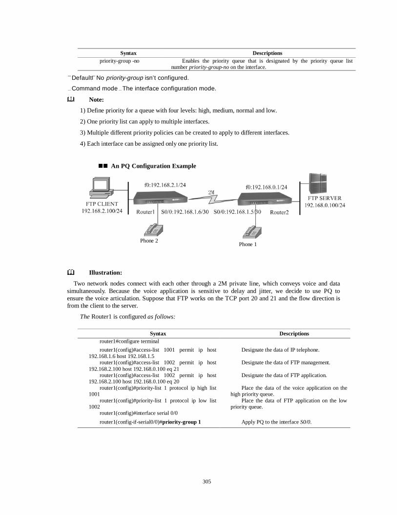
305
�Default�No priority-group isn’t configured.
�Command mode�The interface configuration mode.
Note:
1) Define priority for a queue with four levels: high, medium, normal and low.
2) One priority list can apply to multiple interfaces.
3) Multiple different priority policies can be created to apply to different interfaces.
4) Each interface can be assigned only one priority list.
�� An PQ Configuration Example
Illustration:
Two network nodes connect with each other through a 2M private line, which conveys voice and data simultaneously. Because the voice application is sensitive to delay and jitter, we decide to use PQ to ensure the voice articulation. Suppose that FTP works on the TCP port 20 and 21 and the flow direction is from the client to the server.
The Router1 is configured as follows:
Syntax Descriptions priority-group -no Enables the priority queue that is designated by the priority queue list
number priority-group-no on the interface.
Syntax Descriptions router1#configure terminal
router1(config)#access-list 1001 permit ip host 192.168.1.6 host 192.168.1.5
Designate the data of IP telephone.
router1(config)#access-list 1002 permit ip host 192.168.2.100 host 192.168.0.100 eq 21
Designate the data of FTP management.
router1(config)#access-list 1002 permit ip host 192.168.2.100 host 192.168.0.100 eq 20
Designate the data of FTP application.
router1(config)#priority-list 1 protocol ip high list 1001
Place the data of the voice application on the high priority queue.
router1(config)#priority-list 1 protocol ip low list 1002
Place the data of FTP application on the low priority queue.
router1(config)#interface serial 0/0
router1(config-if-serial0/0)#priority-group 1 Apply PQ to the interface S0/0.
Phone 1 Phone 2
306
�� Monitoring and Debugging PQ
show pq
This command is used to display the statistic information of the current PQ.
show pq
�Command mode�The privilege user mode.
debug pq
This command is used to display the situation of each packet entering the queue.
debug pq
�Command mode�The privilege user mode.
14.2.2.3 CQ (Custom Queuing)
PQ can divide all bandwidth to the key data regardless of data with lower priority. However, CQ can assure the least bandwidth for each class of communication. In the CQ, the system divides the communication into 16 classes, and assigns a queue to each information stream or each kind of information stream. These queues are used to save the packets passing here. For a new packet, the system will class the packet firstly and then put it into the corresponding queue according to the sort. If the corresponding sorting principle isn’t found, then the packet enters the default queue. When dequeuing, the system will do according to queue polling. According to different user configurations each queue possesses, the corresponding account of bytes token from the queues is different. The queue configured with great number of bytes will have more chances to get services.
�� custom-queue-list
Under the global configuration mode, This command is used to a customized queuing rule group, which contains rules that can be adopted when enabling a customized queue on an interface.
custom-queue-list list-number
�Default�No customized queue rule list custom-queue-list is configured.
�Command mode�The global configuration mode.
custom-queue-list list-number fragments min-queue-number max-queue-number
custom-queue-list list-number { gt | lt | et } size-in-byte min-queue-number max-queue-number
Syntax Descriptions list-number It is the serial number of the rule group, and the range of value is between 1
and 16.
Syntax Descriptions Fragments Fragments: set the rule for a packet to enter a queue according to whether a packet is
segmented. min-queue-
number Specify the first queue of the queue group consisting of continuous queues for the
packet matching a rule should enter, and the range of value is between 0 and 16. max-queue-
number Specify the last queue of the queue group consisting of continuous queues for the
packet matching a rule should enter, and the range of value is between 0 and 16.
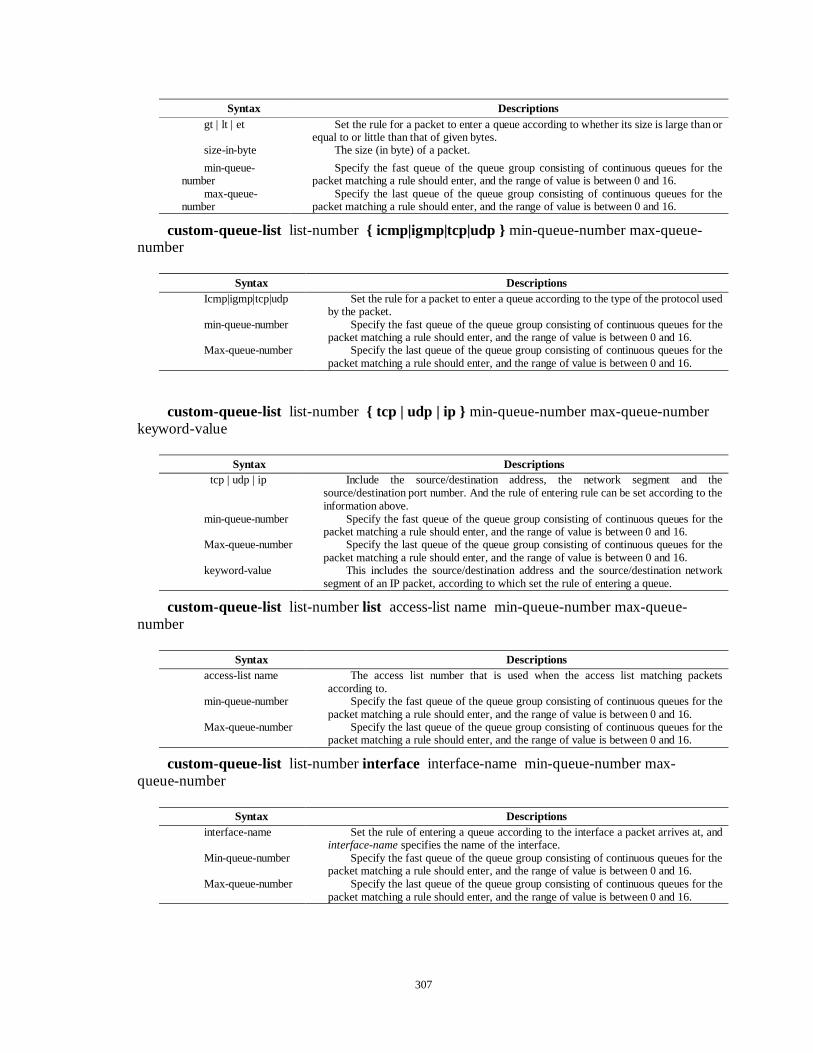
307
custom-queue-list list-number { icmp|igmp|tcp|udp } min-queue-number max-queue-number
custom-queue-list list-number { tcp | udp | ip } min-queue-number max-queue-number keyword-value
custom-queue-list list-number list access-list name min-queue-number max-queue-number
custom-queue-list list-number interface interface-name min-queue-number max-queue-number
Syntax Descriptions gt | lt | et Set the rule for a packet to enter a queue according to whether its size is large than or
equal to or little than that of given bytes. size-in-byte The size (in byte) of a packet.
min-queue-number
Specify the fast queue of the queue group consisting of continuous queues for the packet matching a rule should enter, and the range of value is between 0 and 16.
max-queue-number
Specify the last queue of the queue group consisting of continuous queues for the packet matching a rule should enter, and the range of value is between 0 and 16.
Syntax Descriptions Icmp|igmp|tcp|udp Set the rule for a packet to enter a queue according to the type of the protocol used
by the packet. min-queue-number Specify the fast queue of the queue group consisting of continuous queues for the
packet matching a rule should enter, and the range of value is between 0 and 16. Max-queue-number Specify the last queue of the queue group consisting of continuous queues for the
packet matching a rule should enter, and the range of value is between 0 and 16.
Syntax Descriptions tcp | udp | ip Include the source/destination address, the network segment and the
source/destination port number. And the rule of entering rule can be set according to the information above.
min-queue-number Specify the fast queue of the queue group consisting of continuous queues for the packet matching a rule should enter, and the range of value is between 0 and 16.
Max-queue-number Specify the last queue of the queue group consisting of continuous queues for the packet matching a rule should enter, and the range of value is between 0 and 16.
keyword-value This includes the source/destination address and the source/destination network segment of an IP packet, according to which set the rule of entering a queue.
Syntax Descriptions access-list name The access list number that is used when the access list matching packets
according to. min-queue-number Specify the fast queue of the queue group consisting of continuous queues for the
packet matching a rule should enter, and the range of value is between 0 and 16. Max-queue-number Specify the last queue of the queue group consisting of continuous queues for the
packet matching a rule should enter, and the range of value is between 0 and 16.
Syntax Descriptions interface-name Set the rule of entering a queue according to the interface a packet arrives at, and
interface-name specifies the name of the interface. Min-queue-number Specify the fast queue of the queue group consisting of continuous queues for the
packet matching a rule should enter, and the range of value is between 0 and 16. Max-queue-number Specify the last queue of the queue group consisting of continuous queues for the
packet matching a rule should enter, and the range of value is between 0 and 16.
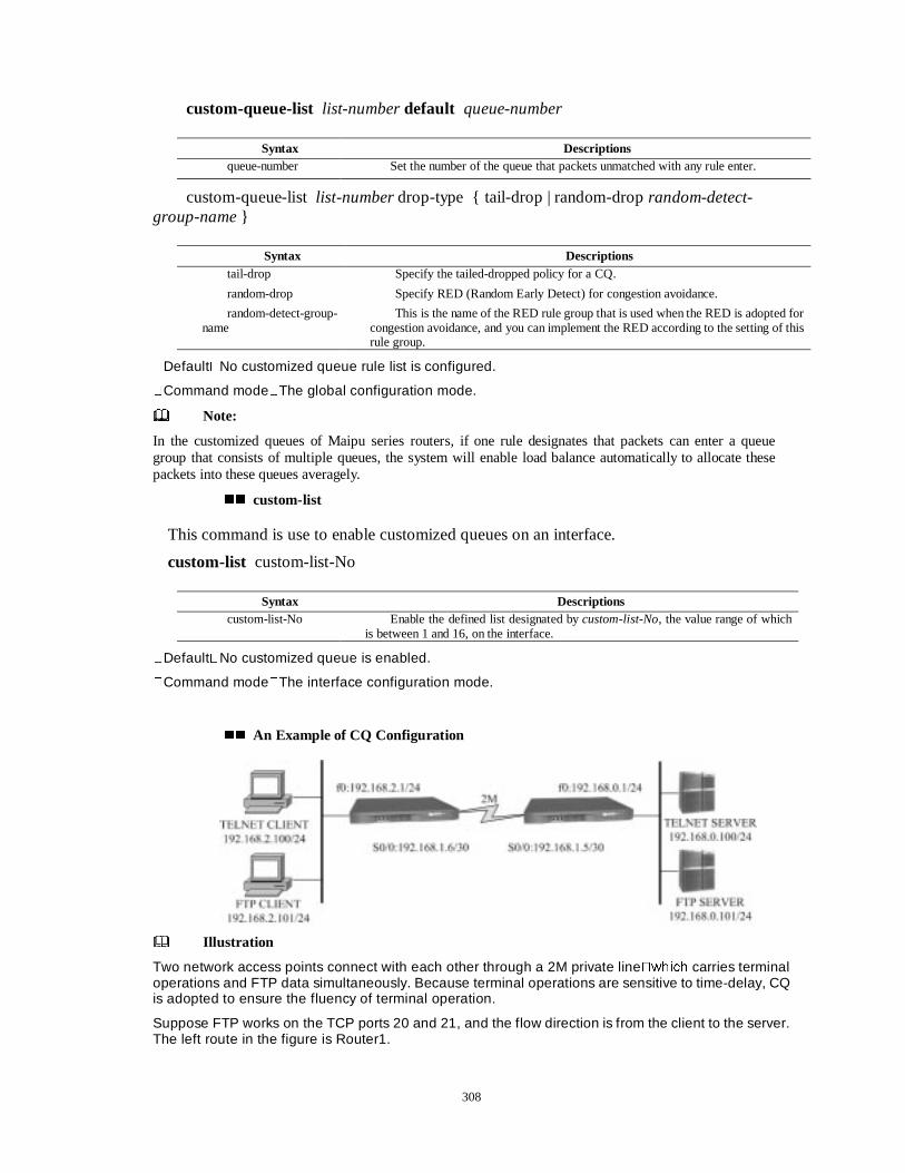
308
custom-queue-list list-number default queue-number
custom-queue-list list-number drop-type { tail-drop | random-drop random-detect-group-name }
�Default�No customized queue rule list is configured.
�Command mode�The global configuration mode.
Note:
In the customized queues of Maipu series routers, if one rule designates that packets can enter a queue group that consists of multiple queues, the system will enable load balance automatically to allocate these packets into these queues averagely.
�� custom-list
This command is use to enable customized queues on an interface.
custom-list custom-list-No
�Default�No customized queue is enabled.
�Command mode�The interface configuration mode.
�� An Example of CQ Configuration
Illustration
Two network access points connect with each other through a 2M private line�ZKLFK carries terminal operations and FTP data simultaneously. Because terminal operations are sensitive to time-delay, CQ is adopted to ensure the fluency of terminal operation.
Suppose FTP works on the TCP ports 20 and 21, and the flow direction is from the client to the server. The left route in the figure is Router1.
Syntax Descriptions queue-number Set the number of the queue that packets unmatched with any rule enter.
Syntax Descriptions tail-drop Specify the tailed-dropped policy for a CQ.
random-drop Specify RED (Random Early Detect) for congestion avoidance.
random-detect-group-name
This is the name of the RED rule group that is used when the RED is adopted for congestion avoidance, and you can implement the RED according to the setting of this rule group.
Syntax Descriptions custom-list-No Enable the defined list designated by custom-list-No, the value range of which
is between 1 and 16, on the interface.
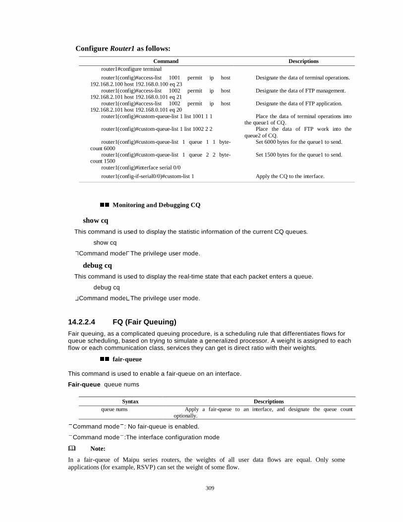
309
Configure Router1 as follows:
Command Descriptions router1#configure terminal
router1(config)#access-list 1001 permit ip host 192.168.2.100 host 192.168.0.100 eq 23
Designate the data of terminal operations.
router1(config)#access-list 1002 permit ip host 192.168.2.101 host 192.168.0.101 eq 21
Designate the data of FTP management.
router1(config)#access-list 1002 permit ip host 192.168.2.101 host 192.168.0.101 eq 20
Designate the data of FTP application.
router1(config)#custom-queue-list 1 list 1001 1 1 Place the data of terminal operations into the queue1 of CQ.
router1(config)#custom-queue-list 1 list 1002 2 2 Place the data of FTP work into the queue2 of CQ.
router1(config)#custom-queue-list 1 queue 1 1 byte-count 6000
Set 6000 bytes for the queue1 to send.
router1(config)#custom-queue-list 1 queue 2 2 byte-count 1500
Set 1500 bytes for the queue1 to send.
router1(config)#interface serial 0/0
router1(config-if-serial0/0)#custom-list 1 Apply the CQ to the interface.
�� Monitoring and Debugging CQ
show cq
This command is used to display the statistic information of the current CQ queues.
show cq
�Command mode�The privilege user mode.
debug cq
This command is used to display the real-time state that each packet enters a queue.
debug cq
�Command mode�The privilege user mode.
14.2.2.4 FQ (Fair Queuing)
Fair queuing, as a complicated queuing procedure, is a scheduling rule that differentiates flows for queue scheduling, based on trying to simulate a generalized processor. A weight is assigned to each flow or each communication class, services they can get is direct ratio with their weights.
�� fair-queue
This command is used to enable a fair-queue on an interface.
Fair-queue queue nums
�Command mode�: No fair-queue is enabled.
�Command mode�:The interface configuration mode
Note:
In a fair-queue of Maipu series routers, the weights of all user data flows are equal. Only some applications (for example, RSVP) can set the weight of some flow.
Syntax Descriptions queue nums Apply a fair-queue to an interface, and designate the queue count
optionally.
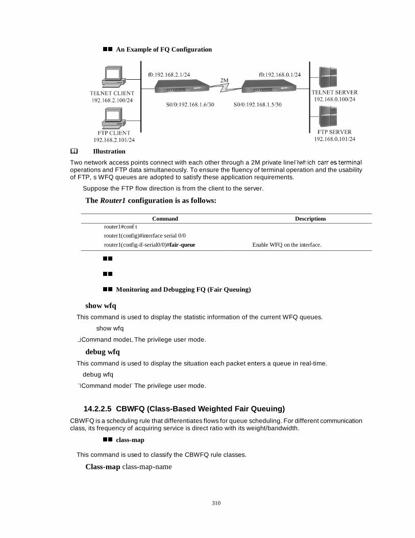
310
�� An Example of FQ Configuration
Illustration
Two network access points connect with each other through a 2M private line�ZKLFK FDUULHV WHUPLQDO
operations and FTP data simultaneously. To ensure the fluency of terminal operation and the usability of FTP, s WFQ queues are adopted to satisfy these application requirements.
Suppose the FTP flow direction is from the client to the server.
The Router1 configuration is as follows:
��
��
�� Monitoring and Debugging FQ (Fair Queuing)
show wfq
This command is used to display the statistic information of the current WFQ queues.
show wfq
�Command mode�The privilege user mode.
debug wfq
This command is used to display the situation each packet enters a queue in real-time.
debug wfq
�Command mode�The privilege user mode.
14.2.2.5 CBWFQ (Class-Based Weighted Fair Queuing)
CBWFQ is a scheduling rule that differentiates flows for queue scheduling. For different communication class, its frequency of acquiring service is direct ratio with its weight/bandwidth.
�� class-map
This command is used to classify the CBWFQ rule classes.
Class-map class-map-name
Command Descriptions router1#conf t
router1(config)#interface serial 0/0
router1(config-if-serial0/0)#fair-queue Enable WFQ on the interface.
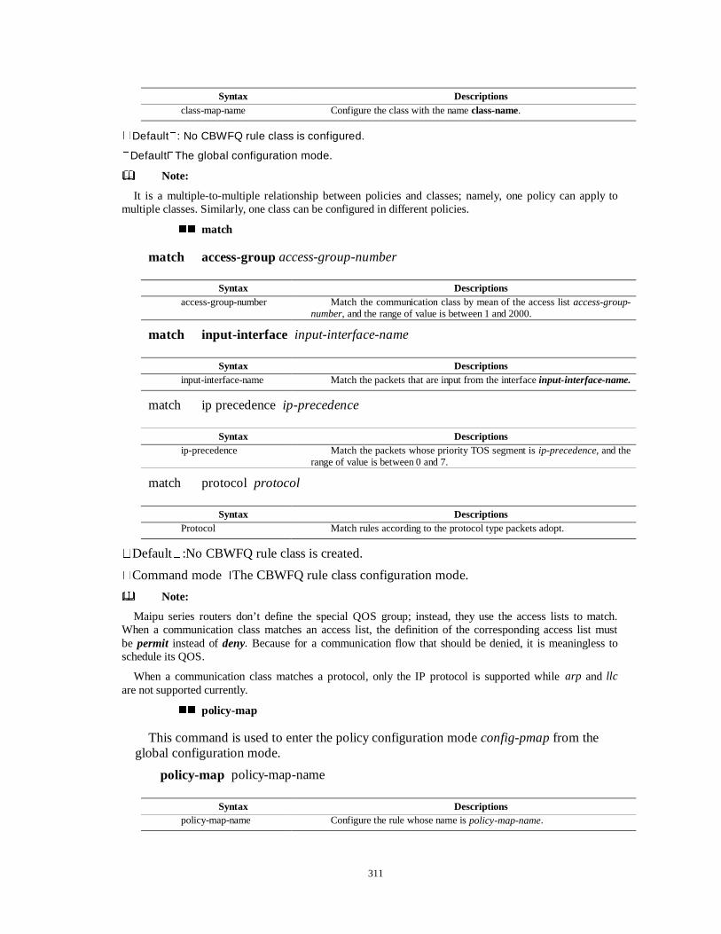
311
�Default�: No CBWFQ rule class is configured.
�Default�The global configuration mode.
Note:
It is a multiple-to-multiple relationship between policies and classes; namely, one policy can apply to multiple classes. Similarly, one class can be configured in different policies.
�� match
match access-group access-group-number
match input-interface input-interface-name
match ip precedence ip-precedence
match protocol protocol
�Default�:No CBWFQ rule class is created.
�Command mode�The CBWFQ rule class configuration mode.
Note:
Maipu series routers don’t define the special QOS group; instead, they use the access lists to match. When a communication class matches an access list, the definition of the corresponding access list must be permit instead of deny. Because for a communication flow that should be denied, it is meaningless to schedule its QOS.
When a communication class matches a protocol, only the IP protocol is supported while arp and llc are not supported currently.
�� policy-map
This command is used to enter the policy configuration mode config-pmap from the global configuration mode.
policy-map policy-map-name
Syntax Descriptions class-map-name Configure the class with the name class-name.
Syntax Descriptions access-group-number Match the communication class by mean of the access list access-group-
number, and the range of value is between 1 and 2000.
Syntax Descriptions input-interface-name Match the packets that are input from the interface input-interface-name.
Syntax Descriptions ip-precedence Match the packets whose priority TOS segment is ip-precedence, and the
range of value is between 0 and 7.
Syntax Descriptions Protocol Match rules according to the protocol type packets adopt.
Syntax Descriptions policy-map-name Configure the rule whose name is policy-map-name.
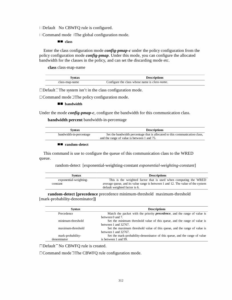
312
�Default�No CBWFQ rule is configured.
�Command mode�The global configuration mode.
�� class
Enter the class configuration mode config-pmap-c under the policy configuration from the policy configuration mode config-pmap. Under this mode, you can configure the allocated bandwidth for the classes in the policy, and can set the discarding mode etc.
class class-map-name
�Default�The system isn’t in the class configuration mode.
�Command mode�The policy configuration mode.
�� bandwidth
Under the mode config-pmap-c, configure the bandwidth for this communication class.
bandwidth percent bandwidth-in-percentage
�� random-detect
This command is use to configure the queue of this communication class to the WRED queue.
random-detect [exponential-weighting-constant exponential-weighting-constant]
random-detect [precedence precedence minimum-threshold maximum-threshold [mark-probability-denominator]]
�Default�No CBWFQ rule is created.
�Command mode�The CBWFQ rule configuration mode.
Syntax Descriptions class-map-name Configure the class whose name is class-name.
Syntax Descriptions bandwidth-in-percentage Set the bandwidth percentage that is allocated to this communication class,
and the range of value is between 1 and 75.
Syntax Descriptions exponential-weighting-
constant This is the weighted factor that is used when computing the WRED
average queue, and its value range is between 1 and 12. The value of the system default weighted factor is 6.
Syntax Descriptions Precedence Match the packet with the priority precedence, and the range of value is
between 0 and 7. minimum-threshold Set the minimum threshold value of this queue, and the range of value is
between 1 and 32767. maximum-threshold Set the maximum threshold value of this queue, and the range of value is
between 1 and 32767. mark-probability-
denominator Set the mark-probability-denominator of this queue, and the range of value
is between 1 and 99.
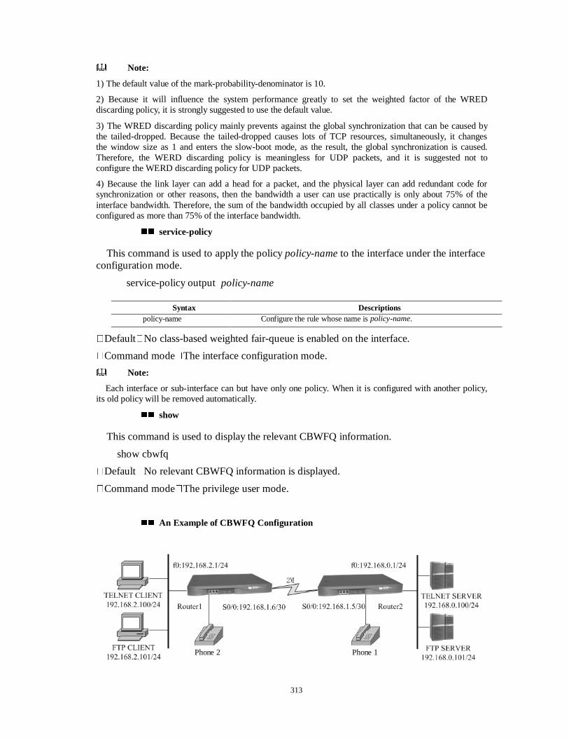
313
Note:
1) The default value of the mark-probability-denominator is 10.
2) Because it will influence the system performance greatly to set the weighted factor of the WRED discarding policy, it is strongly suggested to use the default value.
3) The WRED discarding policy mainly prevents against the global synchronization that can be caused by the tailed-dropped. Because the tailed-dropped causes lots of TCP resources, simultaneously, it changes the window size as 1 and enters the slow-boot mode, as the result, the global synchronization is caused. Therefore, the WERD discarding policy is meaningless for UDP packets, and it is suggested not to configure the WERD discarding policy for UDP packets.
4) Because the link layer can add a head for a packet, and the physical layer can add redundant code for synchronization or other reasons, then the bandwidth a user can use practically is only about 75% of the interface bandwidth. Therefore, the sum of the bandwidth occupied by all classes under a policy cannot be configured as more than 75% of the interface bandwidth.
�� service-policy
This command is used to apply the policy policy-name to the interface under the interface configuration mode.
service-policy output policy-name
�Default�No class-based weighted fair-queue is enabled on the interface.
�Command mode�The interface configuration mode.
Note:
Each interface or sub-interface can but have only one policy. When it is configured with another policy, its old policy will be removed automatically.
�� show
This command is used to display the relevant CBWFQ information.
show cbwfq
�Default�No relevant CBWFQ information is displayed.
�Command mode�The privilege user mode.
�� An Example of CBWFQ Configuration
Syntax Descriptions policy-name Configure the rule whose name is policy-name.
Phone 1 Phone 2
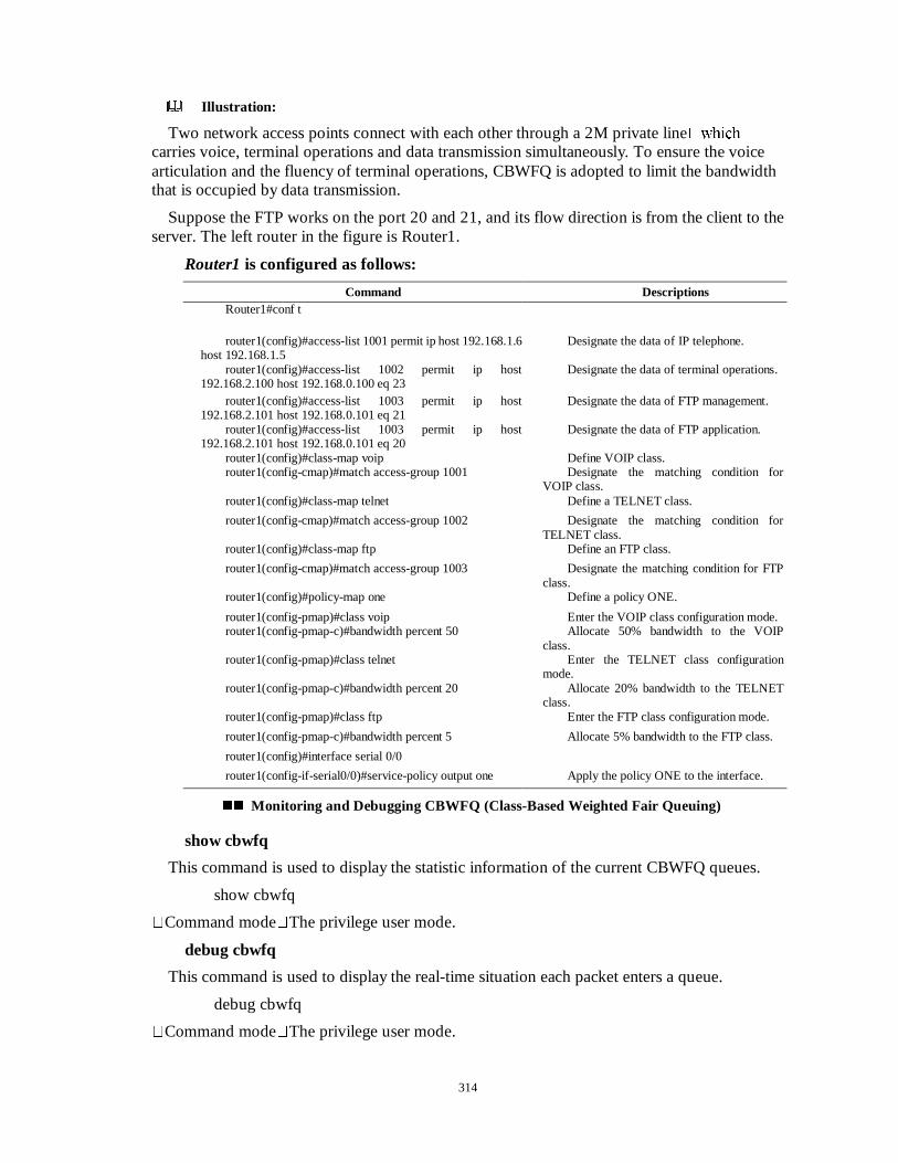
314
Illustration:
Two network access points connect with each other through a 2M private line�ZKLFK
carries voice, terminal operations and data transmission simultaneously. To ensure the voice articulation and the fluency of terminal operations, CBWFQ is adopted to limit the bandwidth that is occupied by data transmission.
Suppose the FTP works on the port 20 and 21, and its flow direction is from the client to the server. The left router in the figure is Router1.
Router1 is configured as follows:
Command Descriptions Router1#conf t
router1(config)#access-list 1001 permit ip host 192.168.1.6 host 192.168.1.5
Designate the data of IP telephone.
router1(config)#access-list 1002 permit ip host 192.168.2.100 host 192.168.0.100 eq 23
Designate the data of terminal operations.
router1(config)#access-list 1003 permit ip host 192.168.2.101 host 192.168.0.101 eq 21
Designate the data of FTP management.
router1(config)#access-list 1003 permit ip host 192.168.2.101 host 192.168.0.101 eq 20
Designate the data of FTP application.
router1(config)#class-map voip Define VOIP class. router1(config-cmap)#match access-group 1001 Designate the matching condition for
VOIP class. router1(config)#class-map telnet Define a TELNET class.
router1(config-cmap)#match access-group 1002 Designate the matching condition for TELNET class.
router1(config)#class-map ftp Define an FTP class.
router1(config-cmap)#match access-group 1003 Designate the matching condition for FTP class.
router1(config)#policy-map one Define a policy ONE.
router1(config-pmap)#class voip Enter the VOIP class configuration mode. router1(config-pmap-c)#bandwidth percent 50 Allocate 50% bandwidth to the VOIP
class. router1(config-pmap)#class telnet Enter the TELNET class configuration
mode. router1(config-pmap-c)#bandwidth percent 20 Allocate 20% bandwidth to the TELNET
class. router1(config-pmap)#class ftp Enter the FTP class configuration mode.
router1(config-pmap-c)#bandwidth percent 5 Allocate 5% bandwidth to the FTP class.
router1(config)#interface serial 0/0
router1(config-if-serial0/0)#service-policy output one Apply the policy ONE to the interface.
�� Monitoring and Debugging CBWFQ (Class-Based Weighted Fair Queuing)
show cbwfq
This command is used to display the statistic information of the current CBWFQ queues.
show cbwfq
�Command mode�The privilege user mode.
debug cbwfq
This command is used to display the real-time situation each packet enters a queue.
debug cbwfq
�Command mode�The privilege user mode.
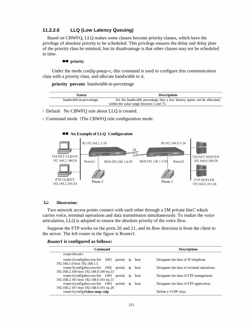
315
11.2.2.6 LLQ (Low Latency Queuing)
Based on CBWFQ, LLQ makes some classes become priority classes, which have the privilege of absolute priority to be scheduled. This privilege ensures the delay and delay jitter of the priority class be minimal, but its disadvantage is that other classes may not be scheduled in time.
�� priority
Under the mode config-pmap-c, this command is used to configure this communication class with a priority class, and allocate bandwidth to it.
priority percent bandwidth-in-percentage
�Default�No CBWFQ rule about LLQ is created.
�Command mode�The CBWFQ rule configuration mode.
�� An Example of LLQ Configuration
Illustration:
Two network access points connect with each other through a 2M private line�ZKLFK
carries voice, terminal operations and data transmission simultaneously. To realize the voice articulation, LLQ is adopted to ensure the absolute priority of the voice flow.
Suppose the FTP works on the ports 20 and 21, and its flow direction is from the client to the server. The left router in the figure is Router1.
Router1 is configured as follows:
Command Descriptions router1#conf t
router1(config)#access-list 1001 permit ip host 192.168.1.6 host 192.168.1.5
Designate the data of IP telephone.
router1(config)#access-list 1002 permit ip host 192.168.2.100 host 192.168.0.100 eq 23
Designate the data of terminal operations.
router1(config)#access-list 1003 permit ip host 192.168.2.101 host 192.168.0.101 eq 21
Designate the data of FTP management.
router1(config)#access-list 1003 permit ip host 192.168.2.101 host 192.168.0.101 eq 20
Designate the data of FTP application.
router1(config)#class-map voip Define a VOIP class.
Syntax Descriptions bandwidth-in-percentage Set the bandwidth percentage that a low latency queue can be allocated,
within the value range between 1 and 75.
Phone 1 Phone 2
316
router1(config-cmap)#match access-group 1001 Designate the matching condition for VOIP class.
router1(config)#class-map telnet Define TELNET class.
router1(config-cmap)#match access-group 1002 Designate the matching condition for TELNET class.
router1(config)#class-map ftp Define an FTP class.
router1(config-cmap)#match access-group 1003 Designate the matching condition for FTP class.
router1(config)#policy-map one Define a policy ONE.
router1(config-pmap)#class voip Enter the VOIP class configuration mode.
router1(config-pmap-c)#priority percent 50 Place VOIP class into LLQ queue.
router1(config-pmap)#class telnet Enter the TELNET class configuration mode.
router1(config-pmap-c)#bandwidth percent 20 Allocate 20% bandwidth to the TELNET class.
router1(config-pmap)#class ftp Enter the FTP class configuration mode.
router1(config-pmap-c)#bandwidth percent 5 Allocate 5% bandwidth to the FTP class.
router1(config)#interface serial 0/0
router1(config-if-serial0/0)#service-policy output one Apply the policy ONE to the interface.
�� Monitoring and Debugging LLQ
show cbwfq
This command is used to display the statistic information of the current CBWFQ queues.
show cbwfq
�Command mode�The privilege user mode.
debug cbwfq
This command is used to display the situation each packet enters a queue in real-time.
debug cbwfq
�Command mode�The privilege user mode.
11.2.3 CgAvD (Congestion Avoidance)
11.2.3.1 RED (Random Early Detect)
RED (Random Early Detect) is a packet discarding policy and a queue management algorithm, and is use to manage the length of the packets and queues in the queuing system. The traditional queue management uses the simple tailed-dropped policy; namely, all arriving packets are discarded when the queue is full. Because the sender may adopt some congestion mechanisms (such as TCP slow-boot), adopting the traditional tailed-dropped can cause the global synchronization of the data source. When the average queue length goes beyond the minimal threshold value, RED employs the reasonable non-zero discarding probability to discard some packets, so as to avoid the global synchronization.
Note:
The details of the configuration command can refer to the section WRED.
11.2.3.2 WRED (Weighted Random Early Detect)
WRED (Weighted Random Early Detect) can designate different RED parameters according to packet priority, so it can ensure the priority of some kinds of communication.
317
Maipu series routers have independent WRED queues, can cooperate with the WERD groups that are used by CQ, PQ and CBWFQ to serve as the discarding policy of several types of queues. The usage of WRED policy in CBWFQ can refers to the section 11.2.2.5.
�� random-detect
When deciding to use WRED as the algorithm for congestion avoidance, you can use this command to enable WRED on an interface, or to configure the enabled WRED parameters on it.
random-detect [ { exponential-weighting-constant exponential-weighting-constant | precedence precedence minimum threshold maximum threshold [mark probability denominator]}]
�Default�:RED isn’t enabled on the interface.
�Command mode�The interface configuration mode.
Note:
The default value of the mark probability denominator is 10.
�� random-detect-group
WRED of Maipu series routers can cooperate with CQ, PQ and CBWFQ to serve as the discarding policy of these queue types. You can, in the global configuration mode, configure RED rule group and use it in other queues. The command random-detect-group can be used to define a RED rule group.
random-detect-group random-detect-group name
�Default�No RED rule group is created.
�Command mode�The global configuration mode.
exponential-weighting-constant weighted-num
precedence precedence minimum-threshold maximu-threshold [mark-probability- denominator]}]
Syntax Descriptions Exponential-weighting-
constant Modify the weighted factor that is used by the average queue
computation of RED on the interface. The default system weighted factor is 6.
Precedence Designate IP priority within the value range being between 0 and 7.
minimum threshold Designate the minimal threshold of the priority queues within the value range being between 1000 and 65535.
maximum threshold Designate the maximal threshold of the priority queues within the value range being between 2000 and 65535.
mark probability denominator
For the optional mark probability denominator, its value range is 1 and 100.
Syntax Descriptions random-detect-group
name Configure a WRED group and designate its name.
Syntax Descriptions weighted-num Configure the weighted factor that is used by the average queue computation
of WRED group. The default system weighted factor is 6.
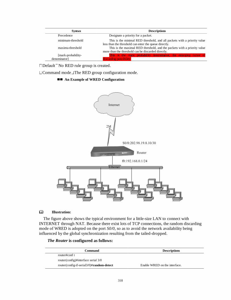
318
�Default�No RED rule group is created.
�Command mode�The RED group configuration mode.
�� An Example of WRED Configuration
Illustration:
The figure above shows the typical environment for a little-size LAN to connect with INTERNET through NAT. Because there exist lots of TCP connections, the random discarding mode of WRED is adopted on the port S0/0, so as to avoid the network availability being influenced by the global synchronization resulting from the tailed-dropped.
The Router is configured as follows:
Syntax Descriptions Precedence Designate a priority for a packet.
minimum-threshold This is the minimal RED threshold, and all packets with a priority value less than the threshold can enter the queue directly.
maximu-threshold This is the maximal RED threshold, and the packets with a priority value more than the threshold can be discarded directly.
[mark-probability-denominator]
This is the mark probability denominator, the enlarging factor of discarding possibility.
Command Descriptions router#conf t
router(config)#interface serial 3/0
router(config-if-serial3/0)#random-detect Enable WRED on the interface.
Ethernet

319
�� Monitoring and Debugging WRED
show wred
This command is used to display the statistic information of the current WRED queue.
show wred
�Command mode�The privilege user mode.
debug wred
This command is used to display the real-time situation each packet enters a queue.
debug wred
�Command mode�The privilege user mode.
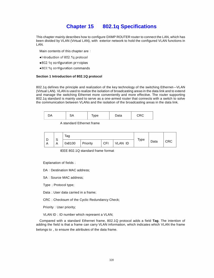
320
Chapter 15 802.1q Specifications
This chapter mainly describes how to configure DXMP ROUTER router to connect the LAN, which has been divided by VLAN (Virtual LAN), with exterior network to hold the configured VLAN functions in LAN.
Main contents of this chapter areÛ
�,QWURGXFWLRQ RI �����T SURWRFRO
������T FRQILJXUDWLRQ SULQFLSOHV
������T FRQILJXUDWion commands
Section 1 Introduction of 802.1Q protocol
802.1q defines the principle and realization of the key technology of the switching Ethernet—VLAN (Virtual LAN). VLAN is used to realize the isolation of broadcasting areas in the data link and to extend and manage the switching Ethernet more conveniently and more effective. The router supporting 802.1q standard is mainly used to serve as a one-armed router that connects with a switch to solve the communication between VLANs and the isolation of the broadcasting areas in the data link.
DA SA Type Data CRC
A standard Ethernet frame
Tag DA
SA 0x8100 Priority CFI VLAN ID
Type Data
CRC
IEEE 802.1Q standard frame format
Explanation of fieldsÛ
DAÛDestination MAC address;
SAÛSource MAC address;
TypeÛProtocol type;
DataÛUser data carried in a frame;
CRCÛChecksum of the Cyclic Redundancy Check;
PriorityÛUser priority;
VLAN IDÛID number which represent a VLAN;
Compared with a standard Ethernet frame, 802.1Q protocol adds a field Tag . The intention of adding the field is that a frame can carry VLAN information, which indicates which VLAN the frame
belongs toÍto ensure the attributes of the data frame.

321
Section 2 802.1Q Configuring Principles
VLAN ID number is added to all equipments in the network by 802.1Q Protocol. The isolating principle of VLAN is that all equipments with the same VLAN ID number of the field Tag in 802.1Q data frame can communicate with each other and other equipments without the same VLAN ID number can’t communicate with each other (If they aren’t included in the same VALN group).
zz VLAN functions
zz Introduction of a one-armed router
• Subnet isolation
2.1 VLAN functions
In the Ethernet supporting 802.1QÍthe Ethernet can be divided into many subnets and each subnet is corresponding to a VLAN(Figure 13-1). When a data frame passes through a switch, the frame is encapsulated again in terms of the frame format defined by 802.1Q standard and the new content called VLAN tag is added to the frame. The tag in the frame describes VLAN the frame belongs to. When the Ethernet interface of the router receives the data frame, the interface judges which VLAN the frame belongs to in terms of its carried tag and compares the VLAN with the corresponding VLAN of the interface. If the receiving interface and the data frame belong to the same VLAN, the interface receives the frame. Or else the frame will be discarded.
When the router sends a data frame, Similarly, the router also encapsulates a tag in the light of 802.1Q standard, The VLAN the tag indicates is the same with the corresponding VLAN of the interface. So the isolation of data frames is realized in the data link layer through the manner of VLAN. Namely, all equipments with the same VLAN can communicate with each other and other equipments without the same VLAN can’t communicate with each other. If communication is needed between VLANs, then it must pass through layer 3 routing. The function should be accomplished by the router.
2.2 One-armed Routing
In order to accomplish the one-armed routing between VLANs, the simplest method is that many links are used between a router and a switch, namely that the Ethernet interface of a router connects with a port of a switch. This kind of connection stands for a VLAN. The method is very simple but it doesn’t make effective use of the interface of the router. So it isn’t an ideal method.
The interface is utilized fully by one-armed routing. The following figure will explain what is one-armed routing.
The switch is configured with two VLANsÛVLAN1 and VLAN2. The port 1 is configured as a relay port. Namely the port 1 belongs to VLAN 1 and VLAN 2. Two sub-interfaces are configured on a fast Ethernet interface of the router. Each sub-interface is assigned to an independent IP subnet and two corresponding VLAN IDs are encapsulated respectively for each sub-interface: VLAN 1 and VLAN 2.
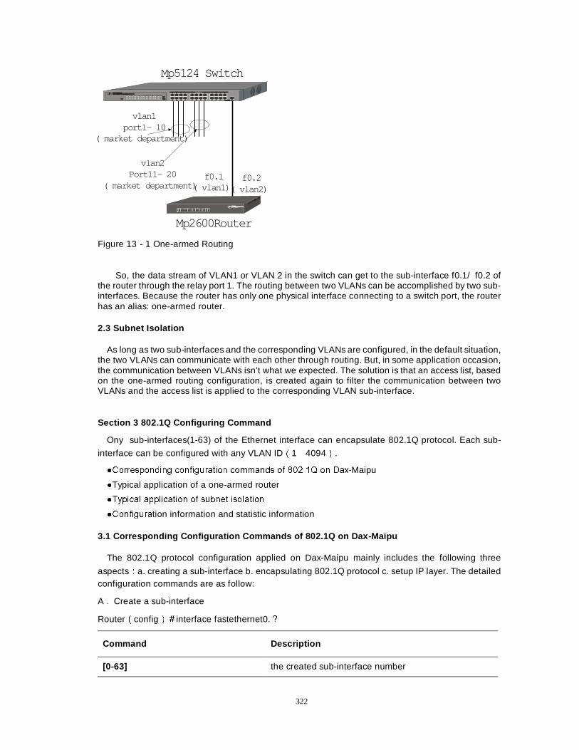
322
vlan2Port11- 20
( market department)
vlan1port1- 10
( market department)
f0.1( vlan1)
f0.2( vlan2)
Mp5124 Switch
Mp2600Router
Figure 13Î1 One-armed Routing
So, the data stream of VLAN1 or VLAN 2 in the switch can get to the sub-interface f0.1/ f0.2 of the router through the relay port 1. The routing between two VLANs can be accomplished by two sub-interfaces. Because the router has only one physical interface connecting to a switch port, the router has an alias: one-armed router.
2.3 Subnet Isolation
As long as two sub-interfaces and the corresponding VLANs are configured, in the default situation, the two VLANs can communicate with each other through routing. But, in some application occasion, the communication between VLANs isn’t what we expected. The solution is that an access list, based on the one-armed routing configuration, is created again to filter the communication between two VLANs and the access list is applied to the corresponding VLAN sub-interface.
Section 3 802.1Q Configuring Command
Ony sub-interfaces(1-63) of the Ethernet interface can encapsulate 802.1Q protocol. Each sub-
interface can be configured with any VLAN IDÉ1Î4094Ê.
�&RUUHVSRQGLQJ FRQILJXUDWLRQ FRPPDQGV RI �����4 RQ 'D[-Maipu
�Typical application of a one-armed router
�7\SLFDO DSSOLFDWLRQ RI VXEQHW LVRODWLRQ
�&RQILJXUDtion information and statistic information
3.1 Corresponding Configuration Commands of 802.1Q on Dax-Maipu
The 802.1Q protocol configuration applied on Dax-Maipu mainly includes the following three
aspectsÛa. creating a sub-interface b. encapsulating 802.1Q protocol c. setup IP layer. The detailed configuration commands are as follow:
AÏ Create a sub-interface
RouterÉconfigÊÄinterface fastethernet0.à
Command Description
[0-63] the created sub-interface number
323
NoteÛÛ
1. The interface fastethernet0.0 is a master interface and can’t encapsulate 802.1Q protocol.
2. Total number of sub-interfaces can’t be more than 63.
BÏ Encapsulating 802.1Q protocol
router(config-if-fastethernet0.1)#
Command Description
encapsulation dot1q < vlan id> Encapsulate 802.1Q protocol on the interface and configure VLAN ID of the interface.
Shutdown Close the interface.
no shutdown Start the interface again.
NoteÛÛ
1) The sub-interface can but only encapsulate 802.1Q protocol. And the protocol has been encapsulated when a sub-interface is created.
2) VLAN ID can only be from 1 to 4094.
CÏ Setup IP layer
router(config-if-fastethernet0.1)# ip ?
Command Description
Address <unicast address> < network mask>
Configure IP address of the sub-interface on the sub-interface.
access-group < IP access list | Access-list name> <in | out>
Apply an access list to the sub-interface.
NoteÛÛ
1) The IP address configured on the sub-interface and IP address of equipments with the same VLAN in LAN should be in the same network segment.
2) If the function of one-armed routing wants to be used, the communication of some equipments must be prohibited and an access list must be applied to the interface.
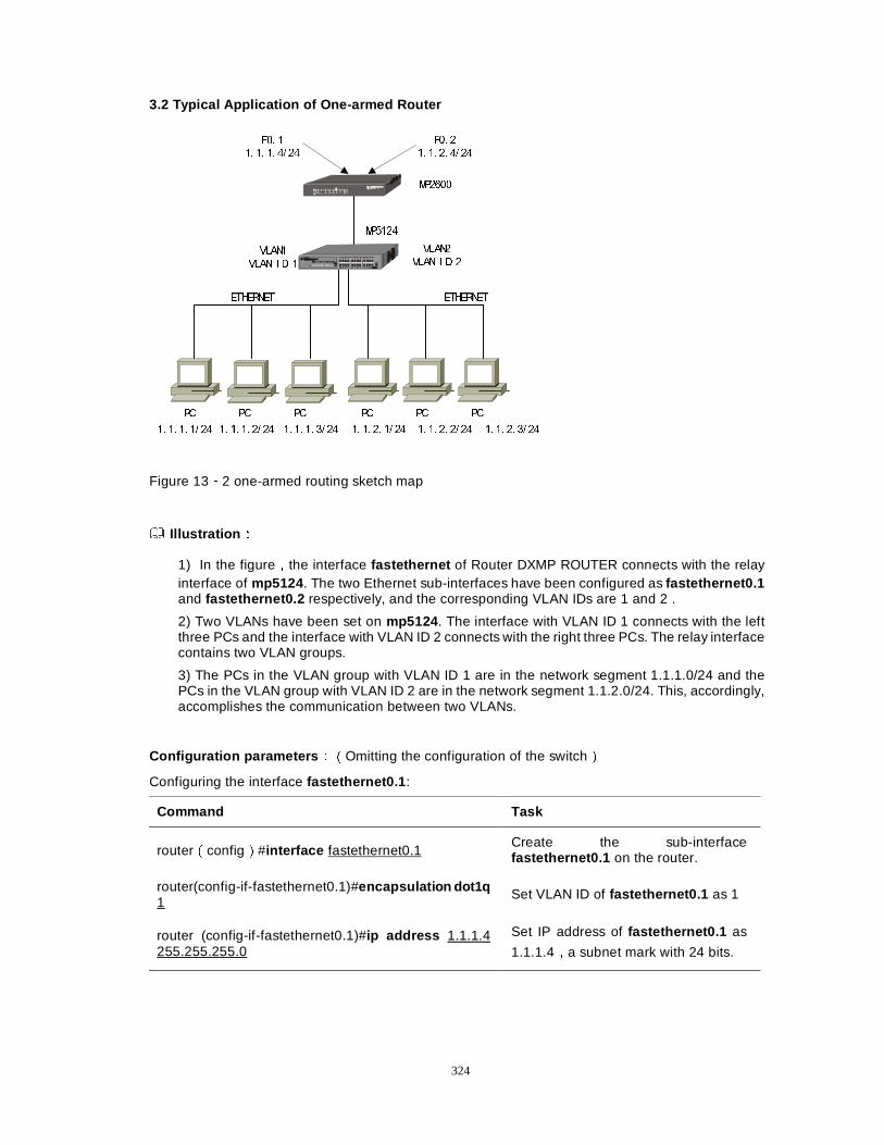
324
3.2 Typical Application of One-armed Router
03����
03����
(7+(51(7 (7+(51(7
3& 3& 3& 3& 3& 3&
9/$1�
9/$1 , ' �
9/$1�
9/$1 , ' �
�� �� �� �� �� �� �� �� �� �� �� �� �� �� ���� �� �� �� �� �� �� �� �� ��
)�� �
�� �� �� �� ��
)�� �
�� �� �� �� ��
�� �� �� �� ��
Figure 13Î2 one-armed routing sketch map
Illustration ÛÛ
1) In the figureÍthe interface fastethernet of Router DXMP ROUTER connects with the relay interface of mp5124 . The two Ethernet sub-interfaces have been configured as fastethernet0.1 and fastethernet0.2 respectively, and the corresponding VLAN IDs are 1 and 2 .
2) Two VLANs have been set on mp5124 . The interface with VLAN ID 1 connects with the left three PCs and the interface with VLAN ID 2 connects with the right three PCs. The relay interface contains two VLAN groups.
3) The PCs in the VLAN group with VLAN ID 1 are in the network segment 1.1.1.0/24 and the PCs in the VLAN group with VLAN ID 2 are in the network segment 1.1.2.0/24. This, accordingly, accomplishes the communication between two VLANs.
Configuration parameters ÛÉOmitting the configuration of the switchÊ
Configuring the interface fastethernet0.1 :
Command Task
routerÉconfigÊ#interface fastethernet0.1 Create the sub-interface fastethernet0.1 on the router.
router(config-if-fastethernet0.1)#encapsulation dot1q 1
Set VLAN ID of fastethernet0.1 as 1
router (config-if-fastethernet0.1)#ip address 1.1.1.4 255.255.255.0
Set IP address of fastethernet0.1 as
1.1.1.4Ía subnet mark with 24 bits.
325
Configuration of the interface fastethernet0.2
Command Task
routerÉconfigÊ#interface fastethernet0.2 Create the sub-interface fastethernet0.2 on the router.
router(config-if-fastethernet0.2)#encapsulation dot1q 2
Set VLAN ID of fastethernet0.2 as 2
router (config-if-fastethernet0.2)#ip address 1.1.2.4 255.255.255.0
Set IP address of fastethernet0.2 as
1.1.2.4Ía subnet mark with 24 bits.
NoteÛÛ
The default gateway of PC in VLAN 1 is set as the IP address (1.1.1.4) of the interface fastethernet0.1 of DXMP ROUTER. And the default gateway of PC in VLAN 2 is set up as the IP address (1.1.2.4) of the interface fastethernet0.2 of DXMP ROUTER.
Configuration result Û
router#show run
Building Configuration...done
hostname router
no service password-encrypt
no service enhanced-secure
interface loopback0
exit
interface fastethernet0
exit
interface fastethernet0.1
ip address 1.1.1.4 255.255.255.0
encapsulation dot1q 1
exit
interface fastethernet0.2
ip address 1.1.2.4 255.255.255.0
encapsulation dot1q 2
exit
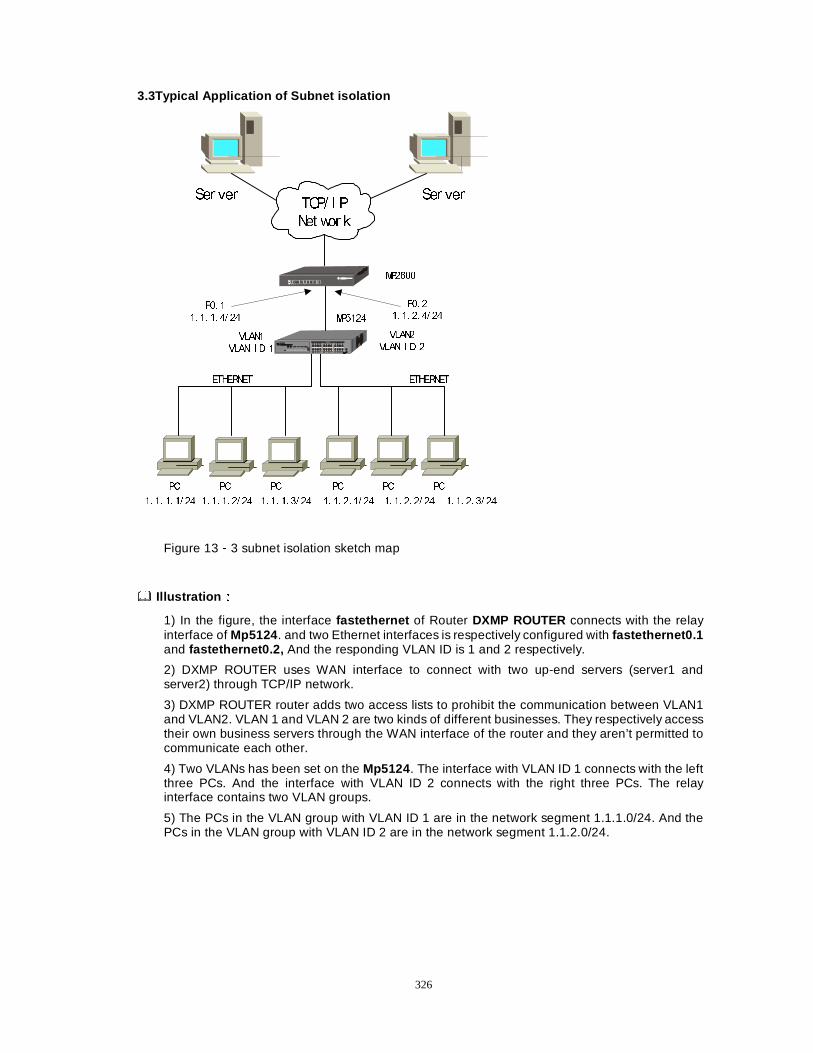
326
3.3Typical Application of Subnet isolation
03����
03����
(7+(51(7 (7+(51(7
3& 3& 3& 3& 3& 3&
9/$1�
9/$1 , ' �
9/$1�
9/$1 , ' �
�� �� �� �� �� �� �� �� �� �� �� �� �� �� ���� �� �� �� �� �� �� �� �� ��
)�� �
�� �� �� �� ��
)�� �
�� �� �� �� ��
�� �� �� �� ��
6HU YHU 6HU YHU7&3� , 3
1HW ZRU N
Figure 13Î3 subnet isolation sketch map
Illustration ÛÛ
1) In the figure, the interface fastethernet of Router DXMP ROUTER connects with the relay interface of Mp5124 . and two Ethernet interfaces is respectively configured with fastethernet0.1 and fastethernet0.2, And the responding VLAN ID is 1 and 2 respectively.
2) DXMP ROUTER uses WAN interface to connect with two up-end servers (server1 and server2) through TCP/IP network.
3) DXMP ROUTER router adds two access lists to prohibit the communication between VLAN1 and VLAN2. VLAN 1 and VLAN 2 are two kinds of different businesses. They respectively access their own business servers through the WAN interface of the router and they aren’t permitted to communicate each other.
4) Two VLANs has been set on the Mp5124 . The interface with VLAN ID 1 connects with the left three PCs. And the interface with VLAN ID 2 connects with the right three PCs. The relay interface contains two VLAN groups.
5) The PCs in the VLAN group with VLAN ID 1 are in the network segment 1.1.1.0/24. And the PCs in the VLAN group with VLAN ID 2 are in the network segment 1.1.2.0/24.
327
Parameter Configuration ÛÉOmitting the configuration of the switchÊ
Configuration of the access list
Command Task
routerÉconfigÊ#ip access-list standard 1 Create a standard access list 1 on the router.
router (config-std-nacl)#deny 1.1.1.0 0.255.255.255 Set the first rule of the access list 1 and prohibit the data from 1.1.1.0/24 from passing through.
router (config-std-nacl)#permit any Set the second rule of the access list 1 and permit any data packet to pass through.
routerÉconfigÊ#ip access-list standard 2 Create a standard access list 2 on the router.
router (config-std-nacl)#deny 1.1.2.0 0.255.255.255 Set the first rule of the access list 2 andprohibit the data from 1.1.2.0/24 frompassing through.
router (config-std-nacl)#permit any Set he second rule of the access list 2 and permit any data packet to pass through.
Configuration of the interface fastethernet0.1
Command Task
routerÉconfigÊ#interface fastethernet0.1 Create the sub-interface fastethernet0.1 on the router.
router (config-if-fastethernet0.1)#encapsulation dot1q 1 Set VLAN ID OF fastethernet0.1 with 1
router (config-if-fastethernet0.1)#ip address 1.1.1.4 255.255.255.0
Set IP address of fastethernet0.1 with 1.1.1.4 and subnet mask with 24 bits.
router (config-if-fastethernet0.1)#ip access-group 2 out Set the data from the interface fastethernet0.1 to be limited by the access list 2.
Configuration of the interface fastethernet0.2
Command Task
ÉconfigÊ#interface fastethernet0.2 Create the sub-interfacefastethernet0.2 on the router.
(config-if-fastethernet0.2)#encapsulation dot1q 2 Set VLAN ID OF fastethernet0.2 with 2
(config-if-fastethernet0.2)#ip address 1.1.2.4 255.255.255.0
Set IP address of fastethernet0.2 with 1.1.2.4 and subnet mask with 24 bits
328
24 bits.
(config-if-fastethernet0.2)#ip access-group 1 out Set the data from the interface fastethernet0.2 and limit it by the access list 1.
Configuration Result Û
router#show run
Building Configuration...done
hostname router hostname router
no service password-encrypt
no service enhanced-secure
ip access-list standard 1 the Standard access control list1
deny 1.1.1.0.0.255.255.255 denying all access from 20.20.0.0
permit any permitting all accesses from other address
exit
ip access-list standard 2 the Standard access control list 2
deny 1.1.2.0 0.0.255.255.255 denying all access from 10.10.0.0
permit any permitting all access from other address
exit
interface loopback0 the loopback address not being defined
exit
interface fastethernet0 the fast Ethernet interface not being defined.
exit
interface fastethernet0.1 Entering the sub-interface f0.1
ip address 1.1.1.4 255.255.255.0 IP address
encapsulation dot1q 1 VLAN ID
ip access-group 2 out SendingÛApplying the access list 2
exit
interface fastethernet0.2 Entering the sub-interface f0.2
ip address 1.1.2.4 255.255.255.0 IP address
encapsulation dot1q 2 VLAN ID
ip access-group 1 out SendingÛApplying the access list 1
exit
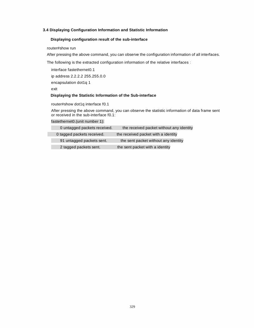
329
3.4 Displaying Configuration Information and Statistic Information
Displaying configuration result of the sub-interface
router#show run
After pressing the above command, you can observe the configuration information of all interfaces.
The following is the extracted configuration information of the relative interfacesÛ
interface fastethernet0.1
ip address 2.2.2.2 255.255.0.0
encapsulation dot1q 1
exit
Displaying the Statistic Information of the Sub-interface
router#show dot1q interface f0.1
After pressing the above command, you can observe the statistic information of data frame sent or received in the sub-interface f0.1:
fastethernet0.(unit number 1):
0 untagged packets received. the received packet without any identity
0 tagged packets received. the received packet with a identity
91 untagged packets sent. the sent packet without any identity
2 tagged packets sent. the sent packet with a identity
330
Chapter 16 Configure DHCP
Section 1 Introduction of DHCP
When a network is too big to control directly by its builder, it is hard to control the network. The frequent problem in the network where IP addresses are assigned manually is IP address conflict. The only method to resolve the problem is to assign IP addresses to customers dynamically. Dynamic Host Configuration Protocol (DHCP) assigns an address from an address pool to the host that requests an address. DHCP also provides other information, such as gateway IP and DNS server. The purpose of designing DHCP is not to provide the diskless workstation with boot information, but to reduce burden of assigning IP addresses manually for a manager. DHCP can accomplish the work of assigning addresses.
Section 2 Configuration of DHC
2.1 DHCP Configuration Task List
�'HILQH DQ DGGUHVV RI DQ DGGUHVV SRRO IRU WKH DVVLJQPHQW RI DGGUHVVHV �&RQILJXUH WKH RSWLRQDO SDUDPHWHUV DVVLJQHG WR D KRVW
2.2The Relative Commands
router#conf t router(config)#ip dhcp ? Command Description
In global mode: Ip dhcp excluded-address Remove addresses from the address pool. Ip dhcp ping Use the parameter ping. Ip dhcp pool Define an address pool for assigning addresses.
Create an HDCPÛÛ
router(config)#ip dhcp pool word Define an address pool and enter DHCP configuration mode. The name of the address pool is the value of word .
router(dhcp-config)# default-router Configure the default gateway of the host. router(dhcp-config)# dns-server Configure DNS server address of the host. router(dhcp-config)# domain-name Configure the server name of the host. router(dhcp-config)# netbios-name-server Configure the address of the server netbios-
name . router(dhcp-config)# network Define the address assigned in the address pool. router(dhcp-config)#exit Exit the interface mode.
2.3Configure DHCP
The first step: Define an address pool applied The first step to star DHCP service is to define an address pool. The addresses in
the address pool will be assigned dynamically to these hosts that use DHCP to request addresses. The following configuration commands should be used on the router:
Command Description router(config)#ip dhcp pool word Define an address pool with the name of word . router(dhcp-config)#network A.B.C.D netmask
Define an address pool for address assignment. And A.B.C.D are network ID and netmask is the network mark.
router(config)#ip dhcp excluded-address Remove the low ip address and high ip address
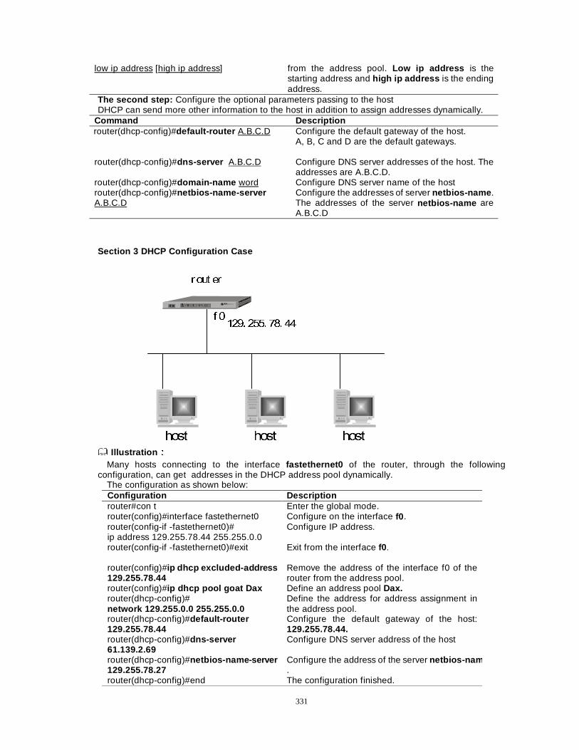
331
low ip address [high ip address]
from the address pool. Low ip address is the starting address and high ip address is the ending address.
The second step: Configure the optional parameters passing to the host DHCP can send more other information to the host in addition to assign addresses dynamically.
Command Description router(dhcp-config)#default-router A.B.C.D Configure the default gateway of the host.
A, B, C and D are the default gateways.
router(dhcp-config)#dns-server A.B.C.D Configure DNS server addresses of the host. The addresses are A.B.C.D.
router(dhcp-config)#domain-name word Configure DNS server name of the host router(dhcp-config)#netbios-name-server A.B.C.D
Configure the addresses of server netbios-name . The addresses of the server netbios-name are A.B.C.D
Section 3 DHCP Configuration Case
I ����� ���� ��� ��
URXW HU
KRVW KRVW KRVW Illustration ÛÛ
Many hosts connecting to the interface fastethernet0 of the router, through the following configuration, can get addresses in the DHCP address pool dynamically.
The configuration as shown below: Configuration Description router#con t Enter the global mode. router(config)#interface fastethernet0 Configure on the interface f0 . router(config-if -fastethernet0)# ip address 129.255.78.44 255.255.0.0
Configure IP address.
router(config-if -fastethernet0)#exit
Exit from the interface f0.
router(config)#ip dhcp excluded-address 129.255.78.44
Remove the address of the interface f0 of the router from the address pool.
router(config)#ip dhcp pool goat Dax Define an address pool Dax. router(dhcp-config)# network 129.255.0.0 255.255.0.0
Define the address for address assignment in the address pool.
router(dhcp-config)#default-router 129.255.78.44
Configure the default gateway of the host: 129.255.78.44.
router(dhcp-config)#dns-server 61.139.2.69
Configure DNS server address of the host
router(dhcp-config)#netbios-name-server 129.255.78.27
Configure the address of the server netbios-na m.
router(dhcp-config)#end The configuration finished.
332
NoteÛÛ The host connecting with the interface fastethernet0 of the router, through the above configuration,
can get the other assigned addresses except 129.255.78.44Éused by the interface fastethernet0 of
the routerÊof the network segment 129.255.0.0. And the host will be configured with the information on DNS server, the default gateway and the server netbios-name .
Section 4 Examine the Status and the Debug
· Examine the host list that currently has been assigned IP address.
ExampleÛ router#show ip dhcp binding Hardware-Address IP-Address Lease Status 0050.ba14.9de5 129.255.0.1 85678 ACKED 0050.ba21.0e6c 129.255.78.2 84765 ACKED
It can be seen from the above information that the two addresses 129.255.0.1 and 129.255.78.2 are respectively assigned to the two hosts with the corresponding MAC address 0050.ba14.9de5 and 0050.ba21.0e6c .
· Trace and debug DHCP information router#debug ip dhcp packet router#debug ip dhcp linkage router#debug ip dhcp events
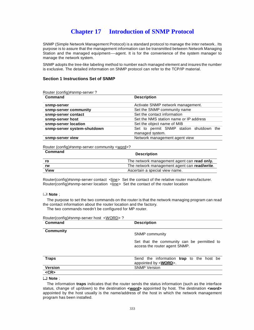
333
Chapter 17 Introduction of SNMP Protocol
SNMP (Simple Network Management Protocol) is a standard protocol to manage the inter network.. Its purpose is to assure that the management information can be transmitted between Network Managing Station and the managed equipment----agent. It is for the convenience of the system manager to manage the network system.
SNMP adopts the tree-like labeling method to number each managed element and insures the number is exclusive. The detailed information on SNMP protocol can refer to the TCP/IP material.
Section 1 Instructions Set of SNMP
Router (config)#snmp-server ? Command Description
snmp-server Activate SNMP network management. snmp-server community Set the SNMP community name snmp-server contact Set the contact information snmp-server host Set the NMS station name or IP address snmp-server location Set the object name of MIB snmp-server system-shutdown Set to permit SNMP station shutdown the
managed system. snmp-server view Network management agent view
Router (config)#snmp-server community <word>?
Command Description
ro The network management agent can read only. rw The network management agent can read/write . View Ascertain a special view name.
Router(config)#snmp-server contact <line> Set the contact of the relative router manufacturer. Router(config)#snmp-server location <line> Set the contact of the router location
NoteÛÛ The purpose to set the two commands on the router is that the network managing program can read
the contact information about the router location and the factory. The two commands needn’t be configured for MP router.
Router(config)#snmp-server host <WORD> ?
Command Description
Community SNMP community
Set that the community can be permitted to access the router agent SNMP.
Traps Send the information trap to the host be
appointed by <WORD>. Version SNMP Version <CR>
NoteÛÛ The information traps indicates that the router sends the status information (such as the interface
status, change of up/down) to the destination <word > appointed by host. The destination <word> appointed by the host usually is the name/address of the host in which the network management program has been installed.
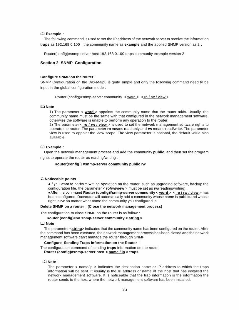
334
ExampleÛÛ The following command is used to set the IP address of the network server to receive the information
traps as 192.168.0.100Íthe community name as example and the applied SNMP version as 2Û Router(config)#snmp-server host 192.168.0.100 traps community example version 2
Section 2 SNMP Configuration
Configure SNMP on the router ÛÛ SNMP Configuration on the Dax-Maipu is quite simple and only the following command need to be
input in the global configuration modeÛ
Router (config)#snmp-server community < word > < ro / rw / view >
NoteÛÛ 1) The parameter < word > appoints the community name that the router adds. Usually, the community name must be the same with that configured in the network management software, otherwise the software is unable to perform any operation to the router. 2) The parameter < ro / rw / view > is used to set the network management software rights to operate the router. The parameter ro means read only and rw means read/write. The parameter view is used to appoint the view scope. The view parameter is optional, the default value also available.
ExampleÛÛ Open the network management process and add the community public , and then set the program
rights to operate the router as reading/writingÛ
Router(config ÊÊ#snmp-server community public rw
� Noticeable points ÛÛ �,I \RX ZDQW WR SHUIRUP ZULWLQJ RSHUation on the router, such as upgrading software, backup the configuration file, the parameter < ro/rw/view > must be set as rw (reading/writing). �$IWHU WKH FRPPDQG Router (config)#snmp-server community < word > < ro / rw / view > has been configured, Daxrouter will automatically add a community whose name is public and whose right is rw no matter what name the community you configured is.
Delete SNMP on a router ÛÛ(Close the network management process)
The configuration to close SNMP on the router is as followÛ Router (config)#no snmp-server community < string >
NoteÛÛ The parameter <string > indicates that the community name has been configured on the router. After
the command has been executed, the network management process has been closed and the network management software can’t manage the router through SNMP.
Configure Sending Traps Information on the Router ÛÛ The configuration command of sending traps information on the route:
Router (config)#snmp-server host < name / ip > traps
NoteÛÛ The parameter < name/ip > indicates the destination name or IP address to which the traps information will be sent. It usually is the IP address or name of the host that has installed the network management software. It is noticeable that the trap information is the information the router sends to the host where the network management software has been installed.
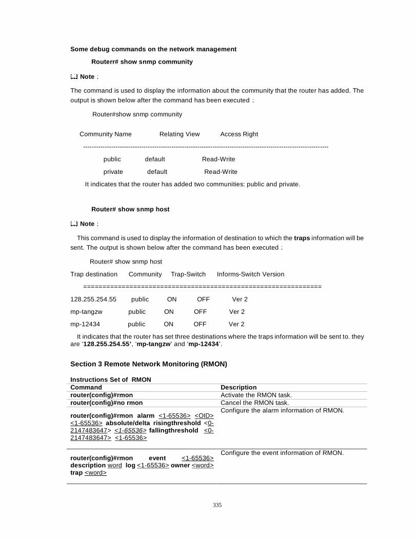
335
Some debug commands on the network management
Routerr# show snmp community
NoteÛÛ
The command is used to display the information about the community that the router has added. The
output is shown below after the command has been executedÛ
Router#show snmp community
Community Name Relating View Access Right
------------------------------------------------------------------------------------------------------------------
public default Read-Write
private default Read-Write
It indicates that the router has added two communities: public and private.
Router# show snmp host
NoteÛÛ
This command is used to display the information of destination to which the traps information will be
sent. The output is shown below after the command has been executedÛ
Router# show snmp host
Trap destination Community Trap-Switch Informs-Switch Version
==============================================================
128.255.254.55 public ON OFF Ver 2
mp-tangzw public ON OFF Ver 2
mp-12434 public ON OFF Ver 2
It indicates that the router has set three destinations where the traps information will be sent to. they are ‘128.255.254.55’, ‘mp-tangzw ’ and ‘mp-12434 ’.
Section 3 Remote Network Monitoring (RMON)
Instructions Set of RMON Command Description router(config)#rmon Activate the RMON task. router(config)#no rmon Cancel the RMON task.
router(config)#rmon alarm <1-65536> <OID> <1-65536> absolute/delta risingthreshold <0-2147483647> <1-65536> fallingthreshold <0-2147483647> <1-65536>
Configure the alarm information of RMON.
router(config)#rmon event <1-65536> description word log <1-65536> owner <word> trap <word>
Configure the event information of RMON.
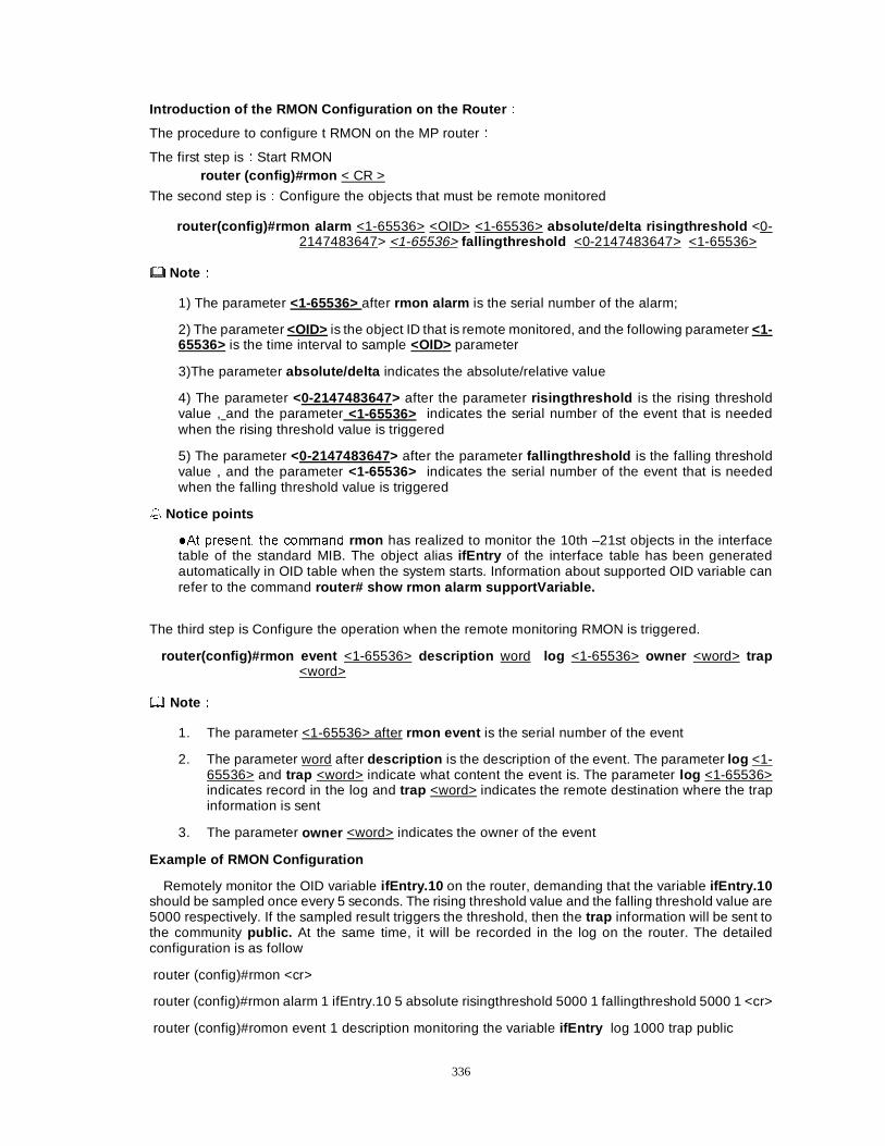
336
Introduction of the RMON Configuration on the Router ÛÛ
The procedure to configure t RMON on the MP routerÛ
The first step isÛStart RMON router (config)#rmon < CR >
The second step isÛConfigure the objects that must be remote monitored
router(config)#rmon alarm <1-65536> <OID> <1-65536> absolute/delta risingthreshold <0-2147483647> <1-65536> fallingthreshold <0-2147483647> <1-65536>
NoteÛÛ
1) The parameter <1-65536> after rmon alarm is the serial number of the alarm;
2) The parameter <OID> is the object ID that is remote monitored, and the following parameter <1-65536> is the time interval to sample <OID> parameter
3)The parameter absolute/delta indicates the absolute/relative value
4) The parameter <0-2147483647> after the parameter risingthreshold is the rising threshold value , and the parameter <1-65536> indicates the serial number of the event that is needed when the rising threshold value is triggered
5) The parameter <0-2147483647> after the parameter fallingthreshold is the falling threshold value , and the parameter <1-65536> indicates the serial number of the event that is needed when the falling threshold value is triggered
� Notice points
�$W SUHVHQW� WKH FRPPDQG rmon has realized to monitor the 10th –21st objects in the interface table of the standard MIB. The object alias ifEntry of the interface table has been generated automatically in OID table when the system starts. Information about supported OID variable can refer to the command router# show rmon alarm supportVariable.
The third step is Configure the operation when the remote monitoring RMON is triggered.
router(config)#rmon event <1-65536> description word log <1-65536> owner <word> trap <word>
NoteÛÛ
1. The parameter <1-65536> after rmon event is the serial number of the event
2. The parameter word after description is the description of the event. The parameter log <1-65536> and trap <word> indicate what content the event is. The parameter log <1-65536> indicates record in the log and trap <word> indicates the remote destination where the trap information is sent
3. The parameter owner <word> indicates the owner of the event
Example of RMON Configuration
Remotely monitor the OID variable ifEntry.10 on the router, demanding that the variable ifEntry.10 should be sampled once every 5 seconds. The rising threshold value and the falling threshold value are 5000 respectively. If the sampled result triggers the threshold, then the trap information will be sent to the community public. At the same time, it will be recorded in the log on the router. The detailed configuration is as follow
router (config)#rmon <cr>
router (config)#rmon alarm 1 ifEntry.10 5 absolute risingthreshold 5000 1 fallingthreshold 5000 1 <cr>
router (config)#romon event 1 description monitoring the variable ifEntry log 1000 trap public
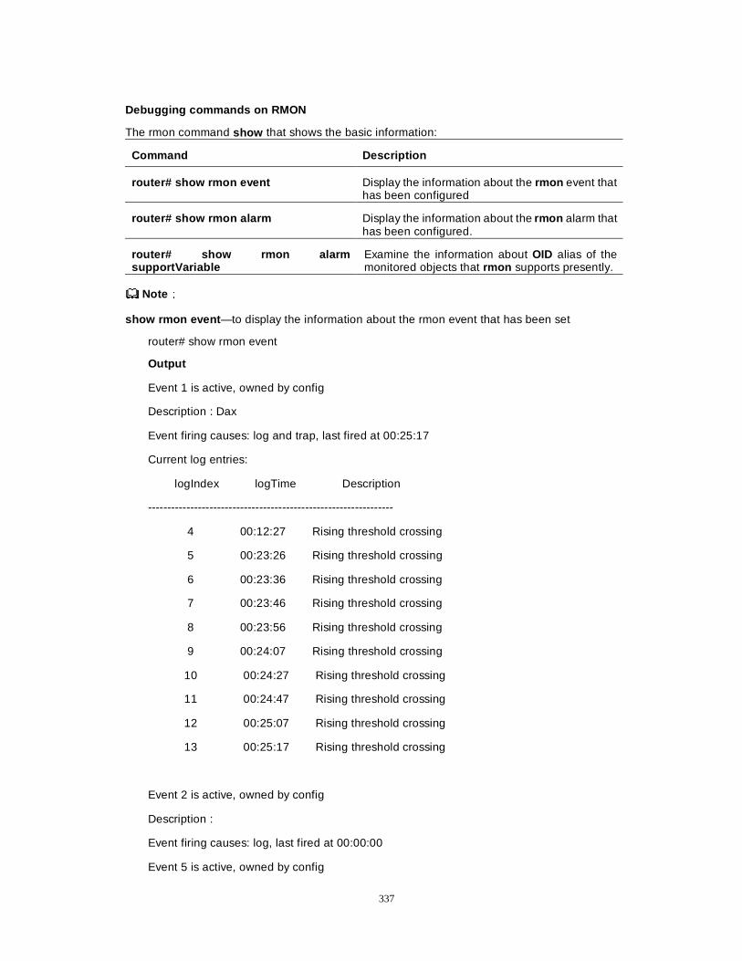
337
Debugging commands on RMON
The rmon command show that shows the basic information:
Command Description
router# show rmon event Display the information about the rmon event that has been configured
router# show rmon alarm Display the information about the rmon alarm that has been configured.
router# show rmon alarm supportVariable
Examine the information about OID alias of the monitored objects that rmon supports presently.
NoteÛÛ
show rmon event —to display the information about the rmon event that has been set
router# show rmon event
Output
Event 1 is active, owned by config
Description : Dax
Event firing causes: log and trap, last fired at 00:25:17
Current log entries:
logIndex logTime Description
----------------------------------------------------------------
4 00:12:27 Rising threshold crossing
5 00:23:26 Rising threshold crossing
6 00:23:36 Rising threshold crossing
7 00:23:46 Rising threshold crossing
8 00:23:56 Rising threshold crossing
9 00:24:07 Rising threshold crossing
10 00:24:27 Rising threshold crossing
11 00:24:47 Rising threshold crossing
12 00:25:07 Rising threshold crossing
13 00:25:17 Rising threshold crossing
Event 2 is active, owned by config
Description :
Event firing causes: log, last fired at 00:00:00
Event 5 is active, owned by config
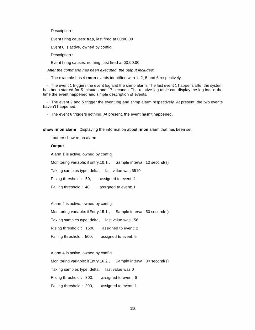
338
Description :
Event firing causes: trap, last fired at 00:00:00
Event 6 is active, owned by config
Description :
Event firing causes: nothing, last fired at 00:00:00
After the command has been executed, the output includes:
· The example has 4 rmon events identified with 1, 2, 5 and 6 respectively.
· The event 1 triggers the event log and the snmp alarm. The last event 1 happens after the system has been started for 5 minutes and 17 seconds. The relative log table can display the log index, the time the event happened and simple description of events.
· The event 2 and 5 trigger the event log and snmp alarm respectively. At present, the two events haven’t happened.
· The event 6 triggers nothing. At present, the event hasn’t happened.
show rmon alarm Displaying the information about rmon alarm that has been set:
router# show rmon alarm
Output
Alarm 1 is active, owned by config
Monitoring variable: ifEntry.10.1 , Sample interval: 10 second(s)
Taking samples type: delta, last value was 6510
Rising threshold : 50, assigned to event: 1
Falling threshold : 40, assigned to event: 1
Alarm 2 is active, owned by config
Monitoring variable: ifEntry.15.1 , Sample interval: 50 second(s)
Taking samples type: delta, last value was 156
Rising threshold : 1500, assigned to event: 2
Falling threshold : 500, assigned to event: 5
Alarm 4 is active, owned by config
Monitoring variable: ifEntry.16.2 , Sample interval: 30 second(s)
Taking samples type: delta, last value was 0
Rising threshold : 300, assigned to event: 6
Falling threshold : 200, assigned to event: 1
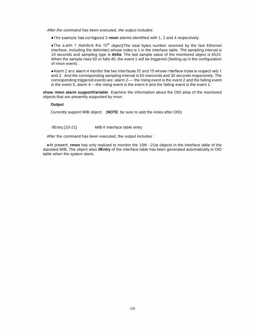
339
After the command has been executed, the output includes:
�7KH H[DPSOH KDV FRQILJXUHG � rmon alarms identified with 1, 2 and 4 respectively.
�7KH DODUP � PRQLWRUV WKH ��th object(The total bytes number received by the fast Ethernet
interface, including the delimiter) whose index is 1 in the interface table. The sampling interval is 10 seconds and sampling type is delta . The last sample value of the monitored object is 6510. When the sample rises 50 or falls 40, the event 1 will be triggered (Setting up in the configuration of rmon event) .
�$ODUP � DQG DODUP � PRQLWRU WKH WZR LQWHUIDFHV �� DQG �� ZKRVH LQWHUIDFH LQGH[ LV UHVSHFWLYHO\ �
and 2. And the corresponding sampling interval is 50 nseconds and 30 seconds respectively. The corresponding triggered events are: alarm 2---- the rising event is the event 2 and the falling event is the event 5, alarm 4----the rising event is the event 6 and the falling event is the event 1.
show rmon alarm supportVariable Examine the information about the OID alias of the monitored objects that are presently supported by rmon.
Output
Currently support MIB object: (NOTE: be sure to add the index after OID)
ifEntry.[10-21] MIB-II interface table entry
After the command has been executed, the output includesÛ
�$W SUHVHQW� rmon has only realized to monitor the 10th –21st objects in the interface table of the standard MIB. The object alias ifEntry of the interface table has been generated automatically in OID table when the system starts.
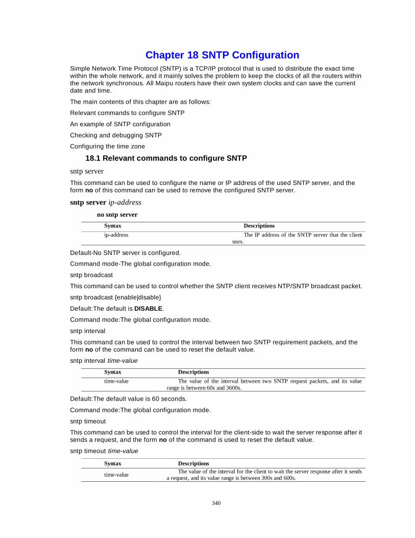
340
Chapter 18 SNTP Configuration Simple Network Time Protocol (SNTP) is a TCP/IP protocol that is used to distribute the exact time within the whole network, and it mainly solves the problem to keep the clocks of all the routers within the network synchronous. All Maipu routers have their own system clocks and can save the current date and time.
The main contents of this chapter are as follows:
Relevant commands to configure SNTP
An example of SNTP configuration
Checking and debugging SNTP
Configuring the time zone
18.1 Relevant commands to configure SNTP
sntp server
This command can be used to configure the name or IP address of the used SNTP server, and the form no of this command can be used to remove the configured SNTP server.
sntp server ip-address
no sntp server
Syntax Descriptions
ip-address The IP address of the SNTP server that the client uses.
Default-No SNTP server is configured.
Command mode-The global configuration mode.
sntp broadcast
This command can be used to control whether the SNTP client receives NTP/SNTP broadcast packet.
sntp broadcast {enable|disable}
Default:The default is DISABLE .
Command mode:The global configuration mode.
sntp interval
This command can be used to control the interval between two SNTP requirement packets, and the form no of the command can be used to reset the default value.
sntp interval time-value
Syntax Descriptions
time-value The value of the interval between two SNTP request packets, and its value range is between 60s and 3600s.
Default:The default value is 60 seconds.
Command mode:The global configuration mode.
sntp timeout
This command can be used to control the interval for the client-side to wait the server response after it sends a request, and the form no of the command is used to reset the default value.
sntp timeout time-value
Syntax Descriptions
time-value The value of the interval for the client to wait the server response after it sends a request, and its value range is between 300s and 600s.
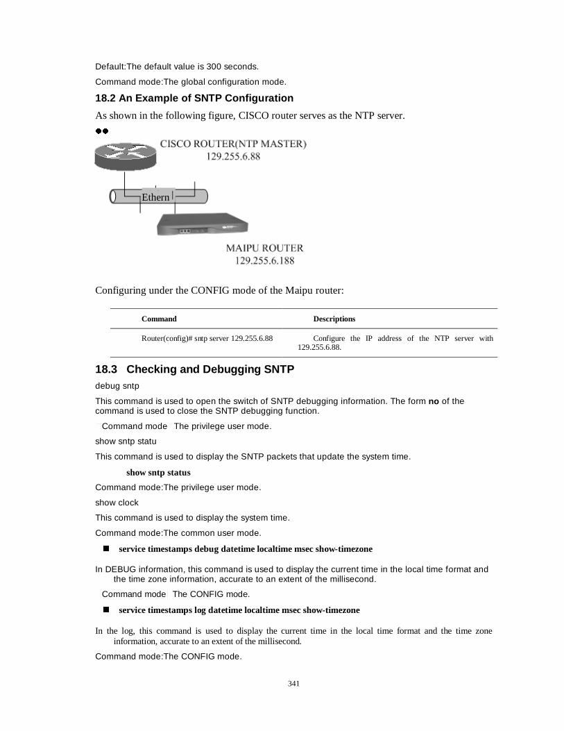
341
Default:The default value is 300 seconds.
Command mode:The global configuration mode.
18.2 An Example of SNTP Configuration
As shown in the following figure, CISCO router serves as the NTP server.
zz
Configuring under the CONFIG mode of the Maipu router:
18.3 Checking and Debugging SNTP debug sntp
This command is used to open the switch of SNTP debugging information. The form no of the command is used to close the SNTP debugging function.
�Command mode�The privilege user mode.
show sntp statu
This command is used to display the SNTP packets that update the system time.
show sntp status
Command mode:The privilege user mode.
show clock
This command is used to display the system time.
Command mode:The common user mode.
� service timestamps debug datetime localtime msec show-timezone
In DEBUG information, this command is used to display the current time in the local time format and the time zone information, accurate to an extent of the millisecond.
�Command mode�The CONFIG mode.
� service timestamps log datetime localtime msec show-timezone
In the log, this command is used to display the current time in the local time format and the time zone information, accurate to an extent of the millisecond.
Command mode:The CONFIG mode.
Command Descriptions
Router(config)# sntp server 129.255.6.88 Configure the IP address of the NTP server with 129.255.6.88.
Ethern
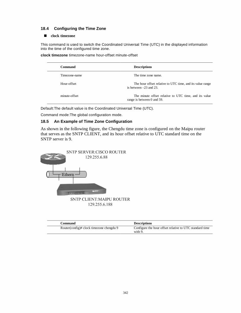
342
18.4 Configuring the Time Zone
� clock timezone
This command is used to switch the Coordinated Universal Time (UTC) in the displayed information into the time of the configured time zone.
clock timezone timezone-name hour-offset minute-offset
Default:The default value is the Coordinated Universal Time (UTC).
Command mode:The global configuration mode.
18.5 An Example of Time Zone Configuration
As shown in the following figure, the Chengdu time zone is configured on the Maipu router that serves as the SNTP CLIENT, and its hour offset relative to UTC standard time on the SNTP server is 9.
Command Descriptions
Timezone-name The time zone name.
Hour-offset The hour offset relative to UTC time, and its value range is between –23 and 23.
minute-offset The minute offset relative to UTC time, and its value range is between 0 and 59.
Command Descriptions Router(config)# clock timezone chengdu 9 Configure the hour offset relative to UTC standard time
with 9.
Ethern
343
Chapter 19 Network Test and Troubleshooting This chapter mainly describes how to use the network test tools of Dax-Maipu and how to diagnose failure.
Main contents of this chapter: �1HWZRUN WHVW WRROV �+RZ to diagnose network failure
Section 1 Network Test Tools
The router provides 4 kinds of test tools in the command status. This section will introduce how to use these tools. Main contents of this section: �&RPPDQG ping ——to test network connectivity and destination reachability �&RPPDQG traceroute ——to test the route information of the data packet �&RPPDQG netstat ——to examine the statuses of network interfaces and detailed statistic information �&RPPDQG show ——to examine the system statistic information and the system statuses
1.1 The Command Ping—to Test Network Connectivity and Destination Reachability
The command ping is mainly used to test the network connectivity and whether the host is reachable. The ping tool currently can only support IP protocol. The command ping can run in the common user mode or in the privileged user mode. Its syntax is as follow:
AÏ In the common user mode Router >ping ?
Command Description
<hostname ipAddress > Set the host name or destination address of ping .
BÏ In the privileged user mode Router #ping ?
Command Description
<hostname ipAddress <CR>> Set the host name or destination address of ping .
NoteÛÛ
1) During the procedure of ping -it can be stopped by the combined keys Ctrl+Shift+6 . 2) After ping command has been executed, the output includes:
A. To each output package, if there is no echo till overtime. Then ‘.’ will be output. Otherwise ‘!’ will be output to show the successful action.
B. The last statistic information includes the number of the sent/received datagram, the percentage of the responded datagram and the minimum/average/maximum value of the responding time.
After the user executes ping <CR>, in the privileged user mode, the optional parameters can be input interactively. The following two cases (in the common user mode and in the privilege user mode) can explain their parameters and its meanings. case 1
In this case, the command ping doesn’t have the extended options. Its format is as follow:
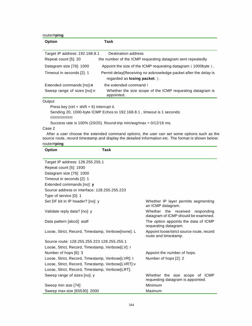
344
router#ping
Option Task
Target IP address: 192.168.8.1 Destination address
Repeat count [5]: 20 the number of the ICMP requesting datagram sent repeatedly
Datagram size [76]: 1000 Appoint the size of the ICMP requesting datagramÉ1000byteÊ.
Timeout in seconds [2]: 1 Permit delay(Receiving no acknowledge packet after the delay is
regarded as losing packet .Ê.
Extended commands [no]:n the extended command � Sweep range of sizes [no]:n Whether the size scope of the ICMP requesting datagram is
appointed.
Output Press key (ctrl + shift + 6) interrupt it. Sending 20, 1000-byte ICMP Echos to 192.168.8.1 , timeout is 1 seconds: !!!!!!!!!!!!!!!!!!!! Success rate is 100% (20/20). Round-trip min/avg/max = 0/12/16 ms.
Case 2 After a user choose the extended command options, the user can set some options such as the
source route, record timestamp and display the detailed information etc. The format is shown below: router#ping
Option Task
Target IP address: 128.255.255.1 Repeat count [5]: 1930
Datagram size [76]: 1000 Timeout in seconds [2]: 1
Extended commands [no]: y
Source address or interface: 128.255.255.223
Type of service [0]: 1 Set DF bit in IP header? [no]: y Whether IP layer permits segmenting
an ICMP datagram.
Validate reply data? [no]: y Whether the received responding datagram of ICMP should be examined.
Data pattern [abcd]: asdf The option appoints the data of ICMP requesting datagram.
Loose, Strict, Record, Timestamp, Verbose[none]: L Appoint loose/strict source route, record route and timestamp.
Source route: 128.255.255.223 128.255.255.1
Loose, Strict, Record, Timestamp, Verbose[LV]: r Number of hops [6]: 3 Appoint the number of hops.
Loose, Strict, Record, Timestamp, Verbose[LVR]: t Number of hops [2]: 2
Loose, Strict, Record, Timestamp, Verbose[LVRT]:v Loose, Strict, Record, Timestamp, Verbose[LRT]:
Sweep range of sizes [no]: y Whether the size scope of ICMP requesting datagram is appointed.
Sweep min size [74]: Minimum
Sweep max size [65530]: 2000 Maxinum
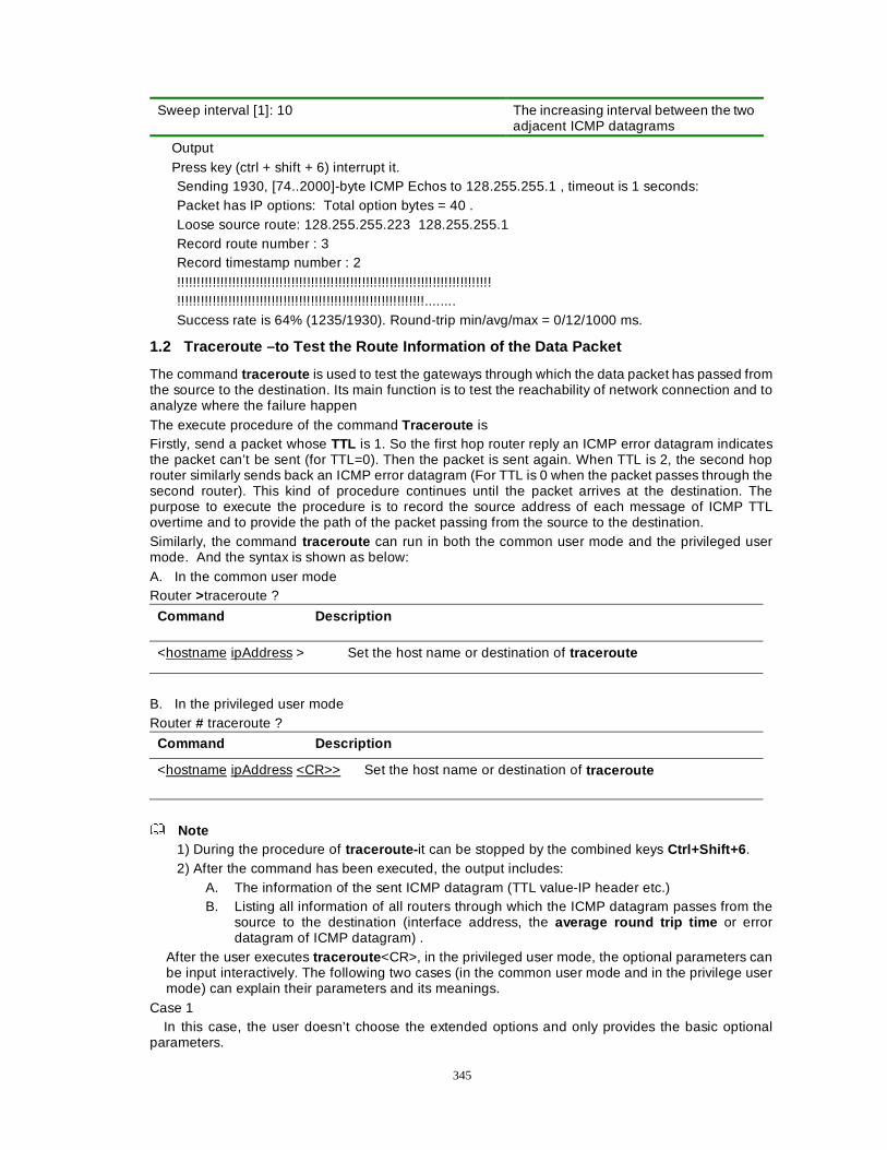
345
Sweep interval [1]: 10 The increasing interval between the two adjacent ICMP datagrams
Output Press key (ctrl + shift + 6) interrupt it. Sending 1930, [74..2000]-byte ICMP Echos to 128.255.255.1 , timeout is 1 seconds: Packet has IP options: Total option bytes = 40 . Loose source route: 128.255.255.223 128.255.255.1 Record route number : 3 Record timestamp number : 2 !!!!!!!!!!!!!!!!!!!!!!!!!!!!!!!!!!!!!!!!!!!!!!!!!!!!!!!!!!!!!!!!!!!!!!!!!!!!!!!! !!!!!!!!!!!!!!!!!!!!!!!!!!!!!!!!!!!!!!!!!!!!!!!!!!!!!!!!!!!!!!!........ Success rate is 64% (1235/1930). Round-trip min/avg/max = 0/12/1000 ms.
1.2 Traceroute –to Test the Route Information of the Data Packet
The command traceroute is used to test the gateways through which the data packet has passed from the source to the destination. Its main function is to test the reachability of network connection and to analyze where the failure happen The execute procedure of the command Traceroute is Firstly, send a packet whose TTL is 1. So the first hop router reply an ICMP error datagram indicates the packet can’t be sent (for TTL=0). Then the packet is sent again. When TTL is 2, the second hop router similarly sends back an ICMP error datagram (For TTL is 0 when the packet passes through the second router). This kind of procedure continues until the packet arrives at the destination. The purpose to execute the procedure is to record the source address of each message of ICMP TTL overtime and to provide the path of the packet passing from the source to the destination. Similarly, the command traceroute can run in both the common user mode and the privileged user mode. And the syntax is shown as below: A. In the common user mode Router >traceroute ?
Command Description
<hostname ipAddress > Set the host name or destination of traceroute
B. In the privileged user mode Router # traceroute ?
Command Description
<hostname ipAddress <CR>> Set the host name or destination of traceroute
Note
1) During the procedure of traceroute- it can be stopped by the combined keys Ctrl+Shift+6 . 2) After the command has been executed, the output includes:
A. The information of the sent ICMP datagram (TTL value-IP header etc.) B. Listing all information of all routers through which the ICMP datagram passes from the
source to the destination (interface address, the average round trip time or error datagram of ICMP datagram) .
After the user executes traceroute <CR>, in the privileged user mode, the optional parameters can be input interactively. The following two cases (in the common user mode and in the privilege user mode) can explain their parameters and its meanings.
Case 1 In this case, the user doesn’t choose the extended options and only provides the basic optional
parameters.
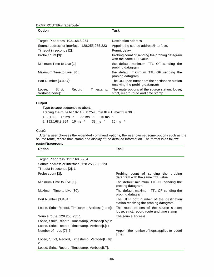
346
DXMP ROUTER#traceroute
Option Task
Target IP address: 192.168.8.254 Destination address
Source address or interface: 128.255.255.223 Appoint the source address/interface. Timeout in seconds [2]: Permit delay.
Probe count [3]: Probing count of sending the probing datagram with the same TTL value
Minimum Time to Live [1]: the default minimum TTL OF sending the probing datagram
Maximum Time to Live [30]: the default maximum TTL OF sending the probing datagram
Port Number [33434]: The UDP port number of the destination station receiving the probing datagram
Loose, Strict, Record, Timestamp, Verbose[none]:
The route options of the source station: loose, strict, record route and time stamp
Output
Type escape sequence to abort. Tracing the route to 192.168.8.254 , min ttl = 1, max ttl = 30 . 1 2.1.1.1 16 ms * 33 ms * 16 ms * 2 192.168.8.254 16 ms * 33 ms * 16 ms *
Case2
After a user chooses the extended command options, the user can set some options such as the source route, record time stamp and display of the detailed information. The format is as follow: router#traceroute
Option Task
Target IP address: 192.168.8.254
Source address or interface: 128.255.255.223 Timeout in seconds [2]: 1
Probe count [3]: Probing count of sending the probing datagram with the same TTL value
Minimum Time to Live [1]: The default minimum TTL OF sending the probing datagram
Maximum Time to Live [30]: The default maximum TTL OF sending the probing datagram
Port Number [33434]: The UDP port number of the destination station receiving the probing datagram
Loose, Strict, Record, Timestamp, Verbose[none]: The route options of the source station: loose, strict, record route and time stamp
Source route: 128.255.255.1 The source address
Loose, Strict, Record, Timestamp, Verbose[LV]: v
Loose, Strict, Record, Timestamp, Verbose[L]: t
Number of hops [7]: 7 Appoint the number of hops applied to record time.
Loose, Strict, Record, Timestamp, Verbose[LTV]: v
Loose, Strict, Record, Timestamp, Verbose[LT]:
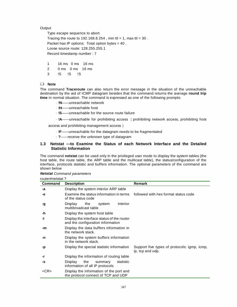
347
Output Type escape sequence to abort. Tracing the route to 192.168.8.254 , min ttl = 1, max ttl = 30 . Packet has IP options: Total option bytes = 40 . Loose source route: 128.255.255.1 Record timestamp number : 7 1 16 ms 0 ms 16 ms 2 0 ms 0 ms 16 ms 3 !S !S !S
Note The command Traceroute can also return the error message in the situation of the unreachable destination by the aid of ICMP datagram besides that the command returns the average round trip time in normal situation. The command is expressed as one of the following prompts:
· !N——unreachable network · !H——unreachable host · !S——unreachable for the source route failure
· !A——unreachable for prohibiting access Éprohibiting network access, prohibiting host
access and prohibiting management accessÊ
· !F——unreachable for the datagram needs to be fragmentated · ?——receive the unknown type of datagram
1.3 Netstat —to Examine the Status of each Network Interface and the Detailed Statistic Information
The command netstat can be used only in the privileged user mode to display the system tables (the host table, the route table, the ARP table and the multicast table), the status/configuration of the interface, protocols statistic and buffers information. The optional parameters of the command are shown below Netstat Command parameters router#netstat ?
Command Description Remark -a Display the system interior ARP table
-e Examine the status information in terms of the status code
followed with hex format status code
-g Display the system interior multibroadcast table
-h Display the system host table
-I Display the interface status of the router and the configuration information
-m Display the data buffers information in the network stack.
-n Display the system buffers information in the network stack.
-p Display the special statistic information Support five types of protocols: igmp, icmp, ip, tcp and udp.
-r Display the information of routing table
-s Display the summary statistic information of all IP protocols
<CR> Display the information of the port and the protocol connect of TCP and UDP
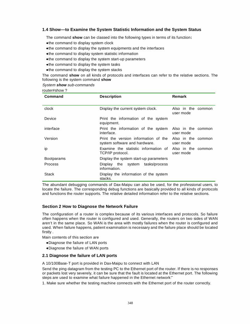
348
1.4 Show—to Examine the System Statistic Information and the System Status
The command show can be classed into the following types in terms of its function: �the command to display system clock �the command to display the system equipments and the interfaces �the command to display system statistic information �the command to display the system start-up parameters �the command to display the system tasks �the command to display the system stacks
The command show on all kinds of protocols and interfaces can refer to the relative sections. The following is the system command show System show sub-commands router#show ?
Command Description Remark
clock Display the current system clock. Also in the common user mode
Device Print the information of the system equipment.
interface Print the information of the system interface.
Also in the common user mode
Version Print the version information of the system software and hardware.
Also in the common user mode
ip Examine the statistic information of TCP/IP protocol.
Also in the common user mode
Bootparams Display the system start-up parameters
Process Display the system tasks/process information.
Stack Display the information of the system stacks.
The abundant debugging commands of Dax-Maipu can also be used, for the professional users, to locate the failure. The corresponding debug functions are basically provided to all kinds of protocols and functions the router supports. The relative detailed information refer to the relative sections.
Section 2 How to Diagnose the Network Failure
The configuration of a router is complex because of its various interfaces and protocols. So failure often happens when the router is configured and used. Generally, the routers on two sides of WAN aren’t in the same place. So WAN is the area with mostly failures when the router is configured and used. When failure happens, patient examination is necessary and the failure place should be located firstly . Main contents of this section are �Diagnose the failure of LAN ports �Diagnose the failure of WAN ports
2.1 Diagnose the failure of LAN ports
A 10/100Base-T port is provided in Dax-Maipu to connect with LAN Send the ping datagram from the testing PC to the Ethernet port of the router. If there is no responses or packets lost very severely, it can be sure that the fault is located at the Ethernet port. The following steps are used to examine what failure happened in the Ethernet network� 1. Make sure whether the testing machine connects with the Ethernet port of the router correctly.
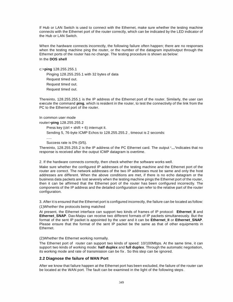
349
If Hub or LAN Switch is used to connect with the Ethernet, make sure whether the testing machine connects with the Ethernet port of the router correctly, which can be indicated by the LED indicator of the Hub or LAN Switch. When the hardware connects incorrectly, the following failure often happen; there are no responses when the testing machine ping the router, or the number of the datagram input/output through the Ethernet ports of the router has no change. The testing procedure is shown as below: In the DOS shell c:>ping 128.255.255.1
Pinging 128.255.255.1 with 32 bytes of data Request timed out. Request timed out. Request timed out.
Thereinto, 128.255.255.1 is the IP address of the Ethernet port of the router. Similarly, the user can execute the command ping , which is resident in the router, to test the connectivity of the link from the PC to the Ethernet port of the router. In common user mode router>ping 128.255.255.2
Press key (ctrl + shift + 6) interrupt it. Sending 5, 76-byte ICMP Echos to 128.255.255.2 , timeout is 2 seconds: ..... Success rate is 0% (0/5).
Thereinto, 128.255.255.2 is the IP address of the PC Ethernet card. The output ‘…’ indicates that no response is received after the output ICMP datagram is overtime. 2. If the hardware connects correctly, then check whether the software works well. Make sure whether the configured IP addresses of the testing machine and the Ethernet port of the router are correct. The network addresses of the two IP addresses must be same and only the host addresses are different. When the above conditions are met, if there is no echo datagram or the business data packets are lost severely when the testing machine pings the Ethernet port of the router, then it can be affirmed that the Ethernet port of the router has been configured incorrectly. The components of the IP address and the detailed configuration can refer to the relative part of the router configuration. 3. After it is ensured that the Ethernet port is configured incorrectly, the failure can be located as follow: (1)Whether the protocols being matched At present, the Ethernet interface can support two kinds of frames of IP protocol: Ethernet_II and Ethernet_SNAP . Dax-Maipu can receive two different formats of IP packets simultaneously. But the format of the sent IP packet is appointed by the user and it can be Ethernet_II or Ethernet_SNAP . Please ensure that the format of the sent IP packet be the same as that of other equipments in Ethernet. (2)Whether the Ethernet working normally. The Ethernet port of router can support two kinds of speed: 10/100Mbps. At the same time, it can support two kinds of working mode: half duplex and full duplex . Through the automatic negotiation, its working mode and rate of transmission can be fix . So this step can be ignored.
2.2 Diagnose the failure of WAN Port
After we know that failure happen at the Ethernet port has been excluded, the failure of the router can be located at the WAN port. The fault can be examined in the light of the following steps�
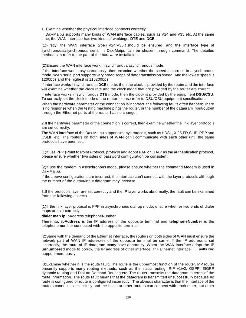
350
1. Examine whether the physical interface connects correctly. Dax-Maipu supports many kinds of WAN interface cables, such as V24 and V35 etc. At the same
time, the WAN interface has two kinds of workings: DTE and DCE.
(1)Firstly, the WAN interface typeÉV24/V35Êshould be ensuredÍand the interface type of synchronous/asynchronous serial in Dax-Maipu can be chosen through command. The detailed method can refer to the part of the hardware installation. (2)Ensure the WAN interface work in synchronous/asynchronous mode. If the interface works asynchronously, then examine whether the speed is correct. In asynchronous mode, WAN serial port supports very broad scope of data transmission speed. And the lowest speed is 1200bps and the highest is 115200bps; If interface works in synchronous DCE mode, then the clock is provided by the router and the interface will examine whether the clock rate and the clock mode that are provided by the router are correct. If interface works in synchronous DTE mode, then the clock is provided by the equipment DSU/CSU. To correctly set the clock mode of the router, please refer to DSU/CSU equipment specifications. When the hardware parameter or the connection is incorrect, the following faults often happen: There is no response when the testing machine pings the router, or the number of the datagram input/output through the Ethernet ports of the router has no change. 2.If the hardware parameter or the connection is correct, then examine whether the link layer protocols are set correctly. The WAN interface of the Dax-Maipu supports many protocols, such as HDSL, X.25,FR,SLIP, PPP and CSLIP etc. The routers on both sides of WAN can‘t communicate with each other until the same protocols have been set. (1)If use PPP (Point to Point Protocol) protocol and adopt PAP or CHAP as the authentication protocol, please ensure whether two sides of password configuration be consistent. (2)If use the modem in asynchronous mode, please ensure whether the command Modem is used in Dax-Maipu. If the above configurations are incorrect, the interface can’t connect with the layer protocols although the number of the output/input datagram may increase. 3.If the protocols layer are set correctly and the IP layer works abnormally, the fault can be examined from the following aspects (1)If the link layer protocol is PPP in asynchronous dial-up mode, ensure whether two ends of dialer maps are set correctly: dialer map ip ipAddress telephoneNumber Thereinto, ipAddress is the IP address of the opposite terminal and telephoneNumber is the telephone number connected with the opposite terminal. (2)Same with the demand of the Ethernet interface, the routers on both sides of WAN must ensure the network part of WAN IP addresses of the opposite terminal be same. If the IP address is set incorrectly, the route of IP datagram many have abnormity. When the WAN interface adopt the IP unnumbered mode to borrow the IP address of other interface�WKH Ethernet interface��)DXOWV FDQ
happen more easily. (3)Examine whether it is the route fault. The route is the uppermost function of the router. MP router presently supports many routing methods, such as the static routing, RIP v1/v2, OSPF, EIGRP dynamic routing and Dial-on-Demand Routing etc. The router transmits the datagram in terms of the route information. The route fault means that the datagram is transmitted unsuccessfully because no route is configured or route is configured incorrectly. The obvious character is that the interface of the routers connects successfully and the hosts or other routers can connect with each other, but other

351
equipments of other network segment can’t be accessed successfully. The method to resolve the problem is: If the static route is adopted, the route must be added manually to the router for the unreachable network segment. If the router adopts RIP, OSPF and EIGRP dynamic route, the router must configure RIP and OSPF route protocol correctly. This makes the router to exchange datagram correctly with the opposite terminal and to update the local routing table.

352
Chapter 20 Software Upgrade The software upgrade of the router includes two aspects of contents. One is the upgrade of ROM
program The relative functions of the program can refer to the chapter 16Ê. The other is the upgrade of the application programs in the router. The following method mainly aims at the upgrade application software.
Dax-Maipu provides two kinds of methods for the software upgrade. These methods can ceaselessly extend functions of the router. The following is to describe the two methods of the software upgrade.
1.The function Hyper Terminal provided by Windows 95/98/NT is used to send the upgrad program to the router through the Console interface (the Upgrade.hex file). The following is the case of the Hyper Terminal program in windows.
Start the Hyper Terminal program and select the corresponding serial (such as com1) and set the attributes: 9600 baud rate, the soft traffic control, eight data bits, no parity and one stop bit. Start the router, press CTRL+C when the start-up information of ROOT shows. And at the same time press the enter key to enter the MONITOR mode.
The command Monitor:>e a is useed to remove the application and its configuration script. After the command is executed, the command Monitor:>speed 115200 is used to set the speed of the Console as 115200bps. At the same time, the speed of the hyper terminal is set as 115200bps (attribute-configuration-baud rate ). Stop the connection in the hyper terminal and start the connection again. Press l <CR> after Monitor:> .
Select the option ‘send the text file ’ in the menu ‘transmit’. After the application program (.hex file) that will be upgraded is chosen, it starts to be transmitted.
After the upgrade ends, set the attributes of the hyper terminal back to the initial setup and restart the router.
NoteÛÛ
1) The purpose to set the baud rate as 115200 is only to advance the transmitting speed and reduce the upgrading time.
2) Use the TFTP mode to upgradeÉ(file name).bin file Ê.
It can be shown in following figure. Open the TFTP server and write the directory in which the upgraded program exists in the column ‘TFTP server root’. PC will be connected to the router through the Ethernet network.
Press sysupdate <IP address of pc > <the file name ((file name).bin ) that will be upgraded > in the privileged user mode of the router. After the file has been transmitted, restart the router and ok.
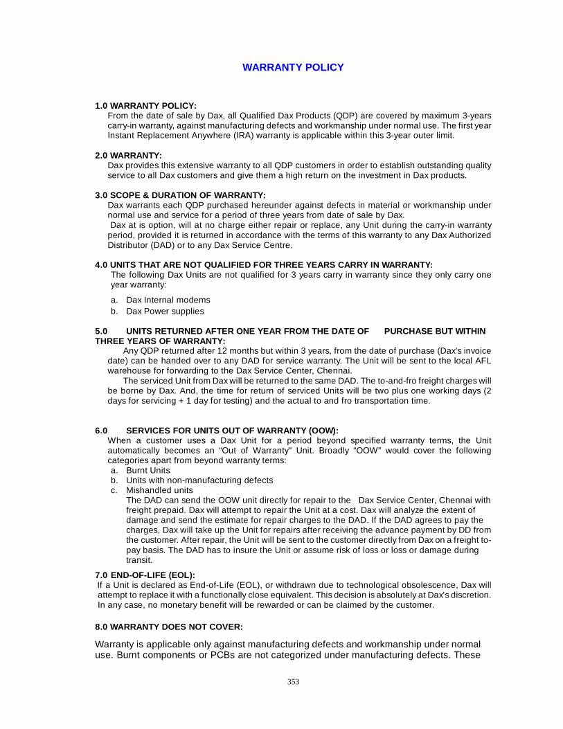
353
WARRANTY POLICY
1.0 WARRANTY POLICY:
From the date of sale by Dax, all Qualified Dax Products (QDP) are covered by maximum 3-years carry-in warranty, against manufacturing defects and workmanship under normal use. The first year Instant Replacement Anywhere (IRA) warranty is applicable within this 3-year outer limit.
2.0 WARRANTY: Dax provides this extensive warranty to all QDP customers in order to establish outstanding quality service to all Dax customers and give them a high return on the investment in Dax products.
3.0 SCOPE & DURATION OF WARRANTY:
Dax warrants each QDP purchased hereunder against defects in material or workmanship under normal use and service for a period of three years from date of sale by Dax. Dax at is option, will at no charge either repair or replace, any Unit during the carry-in warranty period, provided it is returned in accordance with the terms of this warranty to any Dax Authorized Distributor (DAD) or to any Dax Service Centre.
4.0 UNITS THAT ARE NOT QUALIFIED FOR THREE YEARS CARRY IN WARRANTY:
The following Dax Units are not qualified for 3 years carry in warranty since they only carry one year warranty:
a. Dax Internal modems b. Dax Power supplies
5.0 UNITS RETURNED AFTER ONE YEAR FROM THE DATE OF PURCHASE BUT WITHIN THREE YEARS OF WARRANTY:
Any QDP returned after 12 months but within 3 years, from the date of purchase (Dax’s invoice date) can be handed over to any DAD for service warranty. The Unit will be sent to the local AFL warehouse for forwarding to the Dax Service Center, Chennai.
The serviced Unit from Dax will be returned to the same DAD. The to-and-fro freight charges will be borne by Dax. And, the time for return of serviced Units will be two plus one working days (2 days for servicing + 1 day for testing) and the actual to and fro transportation time.
6.0 SERVICES FOR UNITS OUT OF WARRANTY (OOW):
When a customer uses a Dax Unit for a period beyond specified warranty terms, the Unit automatically becomes an “Out of Warranty” Unit. Broadly “OOW” would cover the following categories apart from beyond warranty terms: a. Burnt Units b. Units with non-manufacturing defects c. Mishandled units
The DAD can send the OOW unit directly for repair to the Dax Service Center, Chennai with freight prepaid. Dax will attempt to repair the Unit at a cost. Dax will analyze the extent of damage and send the estimate for repair charges to the DAD. If the DAD agrees to pay the charges, Dax will take up the Unit for repairs after receiving the advance payment by DD from the customer. After repair, the Unit will be sent to the customer directly from Dax on a freight to-pay basis. The DAD has to insure the Unit or assume risk of loss or loss or damage during transit.
7.0 END-OF-LIFE (EOL): If a Unit is declared as End-of-Life (EOL), or withdrawn due to technological obsolescence, Dax will attempt to replace it with a functionally close equivalent. This decision is absolutely at Dax’s discretion. In any case, no monetary benefit will be rewarded or can be claimed by the customer. 8.0 WARRANTY DOES NOT COVER:
Warranty is applicable only against manufacturing defects and workmanship under normal use. Burnt components or PCBs are not categorized under manufacturing defects. These

354
are susceptible to burnouts due to high incoming voltage in telephone lines or in power supplies and also improper Earthing. • Defects or damages to the Units resulting from use of Units in an operating environment
other than as specified in the User Manual. • Defects or damages resulting from accidents, misuse or neglect or any natural
calamities. • Defects or damages from improper testing, operation, maintenance, installation,
alteration, modification or adjustments. • Breakage or damage to the Unit caused due to mishandling. • Units dismantled or attempted to repair. • Units that have had their serial numbers removed or tampered with. • Defects or damages due to spill of food or liquid. • All outer surfaces and all other externally exposed parts that are scratched or damaged
due to customer’s abnormal use. • Units if physically tampered with by unauthorized persons. 9.0 JURISDICTION
Any dispute shall be subject to exclusive jurisdiction of the courts in Chennai.
10.0 CONTACT DETAILS OF DAX NETWORKS LIMITED AND SERVICE CENTRE:
Dax Networks Limited 79, Chamiers Road, Chennai 600 028
Ph. No.: 2432 3557 / 2432 3558 / 2432 3984 FAX NO. 044 – 2435 7267
Service Centre
New No. 21(Old No.11), II Street, R.K. Nagar, Mandaveli, Chennai – 28.
Ph. No.: 2462 0217 / 2462 0218
E-MAIL: [email protected] Contact: Manager – IRA
Co-ordinator – Service Centre Please refer our website www.daxnetworks.com for the current updated address and contact phone
numbers.

355
WARRANTY CARD FOR DXMP Common Router Manual
This DXMP Common Router Manual has been manufactured under the most stringent quality standards by an ISO 9001 Certified Company and is guaranteed to perform. This DXMP Common Router Manual carries a comprehensive 3-year warranty. In the unlikely event of the product malfunctioning due to any manufacturing defect, you can get it exchanged instantly as per our IRA (Instant Replacement Anywhere) policy guidelines within one year of purchase from date of sale by Dax or get it repaired / replaced at free of charge with in the Carry-in warranty period. For replacement or repair, please walk-in with the product to your vendor or any Dax authorized distributor. Just make sure that you produce this card and the serial number of your product along with proof of date of purchase when you require replacement / repair. For any additional support, please contact the Dax Technical Support Department at
DAX NETWORKS LTD., 79, Chamiers Road, Chennai - 600 028. India
Ph: 044 - 2432 3558 Fax: 044 - 2435 7267 Email: [email protected] Website: www.daxnetworks.com
Note: Please refer our website for IRA / Support Centers & Dax Authorized Distributors.