David Sagan Cornell Laboratory for Accelerator-Based ... · 9/19/2014 · David Sagan September...
32
Accelerator & X-ray Modeling Using the Bmad Software Library David Sagan Cornell Laboratory for Accelerator-Based Sciences and Education
Transcript of David Sagan Cornell Laboratory for Accelerator-Based ... · 9/19/2014 · David Sagan September...

Accelerator & X-ray Modeling Using the Bmad Software Library
David Sagan Cornell Laboratory for
Accelerator-Based Sciences and Education

David Sagan September 19, 2014 KEK 2
Talk Outline
• Overview & history • Tao program • Useful features • Bmad ecosystem of programs • Future plans • Conclusion

David Sagan September 19, 2014 KEK 3
Overview
• Bmad is a library toolkit. Not a program • Written in Fortran. • Object oriented from the ground up. • Has structure translation code for interfacing
with C++. • Lattice files use a MAD like syntax. • Documented. • Open Source:
http://www.lepp.cornell.edu/~dcs/bmad/
David Sagan September 19, 2014 KEK 4
In the Beginning…
Brief History: • Born at Cornell in mid 1990’s • Started life as modest project: Just
wanted to calculate Twiss functions and closed orbit. • Initially Bmad used a subset of the
MAD lattice syntax. Hence the name: “Baby MAD” or “Bmad” for short.
Over the years Bmad had evolved…
David Sagan September 19, 2014 KEK 5
And Baby Grows Up...
Currently: • ~100,000 lines of code • ~1,000 routines
And it can do much more: • X-ray simulations • Spin tracking • Tracking with coherent synchrotron radiation • Wakefields and HOMs • Beam breakup simulations in ERLs • Intra-beam scattering (IBS) simulations • Touschek lifetime • Frequency map analysis • Dark current tracking • Etc., etc.

David Sagan September 19, 2014 KEK 6
Bmad Philosophy
Question: Why is Bmad constructed as a library toolkit? Answer: Flexibility!
Advantages of a toolkit: • Cuts down on the time needed to develop
programs. • Cuts down on programming errors. • Standardizes sharing of lattice information
between programs.
Bmad Dynamic Aperture Program
Control System Programs
Lattice Design Program
Etc.
Etc.

David Sagan September 19, 2014 KEK 7
Tao with Bmad gives the flexibility of a library with the convenience of a program.
Tao: Tool for Accelerator Optics
0 20 40 60 80 100 120
10
5
0
-5
-10
10
5
0
-5
-10
10
5
0
-5
-10
Orbit [meas]
Orbit [meas - model]
Orbit [meas - model]
Data
Data - Unfitted Model
Data - Fitted Model
X O
rbit
(mm
)X
Orb
it (m
m)
X O
rbit
(mm
)
140S (m)
JLab FEL Modeling
Problem: Bmad is not a program so it cannot be used “out of the box.” for simple calculations.
Solution: Develop Tao - a general purpose simulation & design program with • Nonlinear optimization. • Twiss and orbit calculations • Etc.
Additionally: Tao’s object oriented coding makes it relatively easy to extend it. • For example: Can add custom commands to interface Tao with a control system.

David Sagan September 19, 2014 KEK 8
Bmad Features
Bmad has a number of features that over the years have proven useful...
David Sagan September 19, 2014 KEK 9
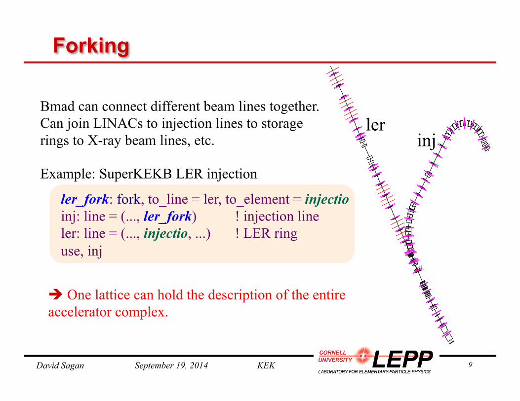
ler_fork: fork, to_line = ler, to_element = injectio inj: line = (..., ler_fork) ! injection line ler: line = (..., injectio, ...) ! LER ring use, inj
Forking
Bmad can connect different beam lines together. Can join LINACs to injection lines to storage rings to X-ray beam lines, etc.
Example: SuperKEKB LER injection
è One lattice can hold the description of the entire accelerator complex.
inj ler

David Sagan September 19, 2014 KEK 10
Multipass Bmad can simulate beam lines having common elements Example: SuperKEKB IR region:
CEBAF
SuperKEKB
sol: line[multipass] = (esle4000, ..., esre4000) pt1_l: patch, ...; pt2_l: patch, ... pt1_h: patch, ...; pt2_h: patch, ... mm: marker fid: fiducial, origin_ele = mm ler: line = (pt2_l, mm, sol, pt1_l, ler_arc) her: line = (pt2_h, --sol, fid, pt1_h, her_arc) use, ler, her
sol
LER ref orbit HER ref orbit
Changes to elements in sol get reflected in both HER and LER lines.
patch patch
David Sagan September 19, 2014 KEK 11
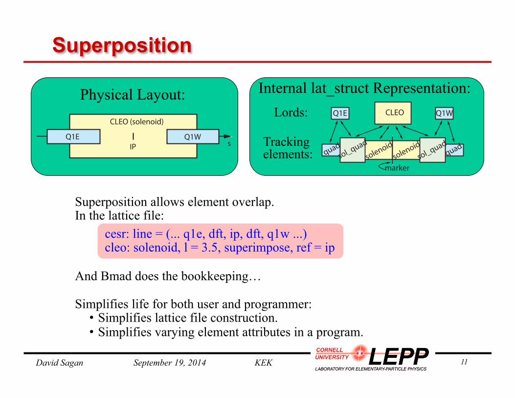
Superposition
CLEOQ1E Q1W
sol_qua
dqua
dsole
noid
marker
quad
sol_qua
dsole
noid
Physical Layout: Internal lat_struct Representation: Lords:
Tracking elements:
Superposition allows element overlap. In the lattice file:
cesr: line = (... q1e, dft, ip, dft, q1w ...) cleo: solenoid, l = 3.5, superimpose, ref = ip
And Bmad does the bookkeeping… Simplifies life for both user and programmer: • Simplifies lattice file construction. • Simplifies varying element attributes in a program.
CLEO (solenoid)
Q1WQ1EIP s

David Sagan September 19, 2014 KEK 12
• bmad_standard Fast, nonsymplectic • symp_lie_ptc Symplectic tracking using PTC • taylor Taylor map (generated via PTC) • linear Linear tracking • custom Tracking with custom code • runge_kutta Track through fields. • etc.
Tracking Method Selection Can set how each element is tracked on an element-by-element basis:
Advantages: • Enables simulation of unique element types • Can compare different tracking methods
Example: inflector: em_field, tracking_method = runge_kutta, field_calc = custom, ...

David Sagan September 19, 2014 KEK 13
Etienne Forest’s FPP/PTC
Integration with Bmad: • Interface routines between Bmad and PTC
allow tracking of individual elements • PTC lattices can be constructed for analysis • In cooperation with Etienne, PTC now can
handle KEKB lattices
Application of PTC_ORBIT for J-PARC Main Ring study
0 200 400 600 800 1000-0.5
0.0
0.5
1.0
1.5
2.0
2.5 NO LCC Global LCC
D99
H_E
mitt
ance
[pi.m
m.m
rad]
Number of Turns
0.6 0.7 0.8 0.9 1
1
2
3
4
5
0.6 0.7 0.8 0.9 1
1
2
3
4
5
Effects of the high order resonances before and after the linear coupling [1,1,43] resonance correction, caused by the machine imperfection and the space charge
This work is supported by the Large Scale Simulation Program No.0806 (FY2008) of High Energy Accelerator Research Organization (KEK).
Spectrum analysis of the high-order coupling coherent mode <X2Y2>, including the alignment errors of the MR magnets and the low energy space charge effects
Before correction
After correction
Frequency
Am
plitu
de
Frequency
Am
plitu
de
99% emittance growth (1.8kW/bunch) at the injection energy of 3GeV before and after the global [1,1,43] resonance correction:
Remained emittance dilution is caused by the effects of high-order resonances [4,0,89], [ 0,4,83] and [2,2,86].
Alexander Molodozhentsev PTC_ORBIT combined code KEK & SNS common activity
Etienne Forest’s FPP/PTC simulation toolkit: • Can construct Taylor series maps to
arbitrary order via symplectic Lee integration through elements.
• Can include spin tracking. • Can do such things as normal form
analysis to extract resonance strengths. • Is used in MAD-X & PTC_ORBIT
David Sagan September 19, 2014 KEK 14
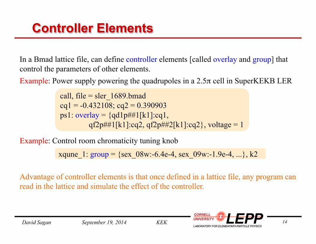
Controller Elements
In a Bmad lattice file, can define controller elements [called overlay and group] that control the parameters of other elements. Example: Power supply powering the quadrupoles in a 2.5π cell in SuperKEKB LER Example: Control room chromaticity tuning knob
Advantage of controller elements is that once defined in a lattice file, any program can read in the lattice and simulate the effect of the controller.
call, file = sler_1689.bmad cq1 = -0.432108; cq2 = 0.390903 ps1: overlay = {qd1p##1[k1]:cq1,
qf2p##1[k1]:cq2, qf2p##2[k1]:cq2}, voltage = 1
xqune_1: group = {sex_08w:-6.4e-4, sex_09w:-1.9e-4, ...}, k2
David Sagan September 19, 2014 KEK 15
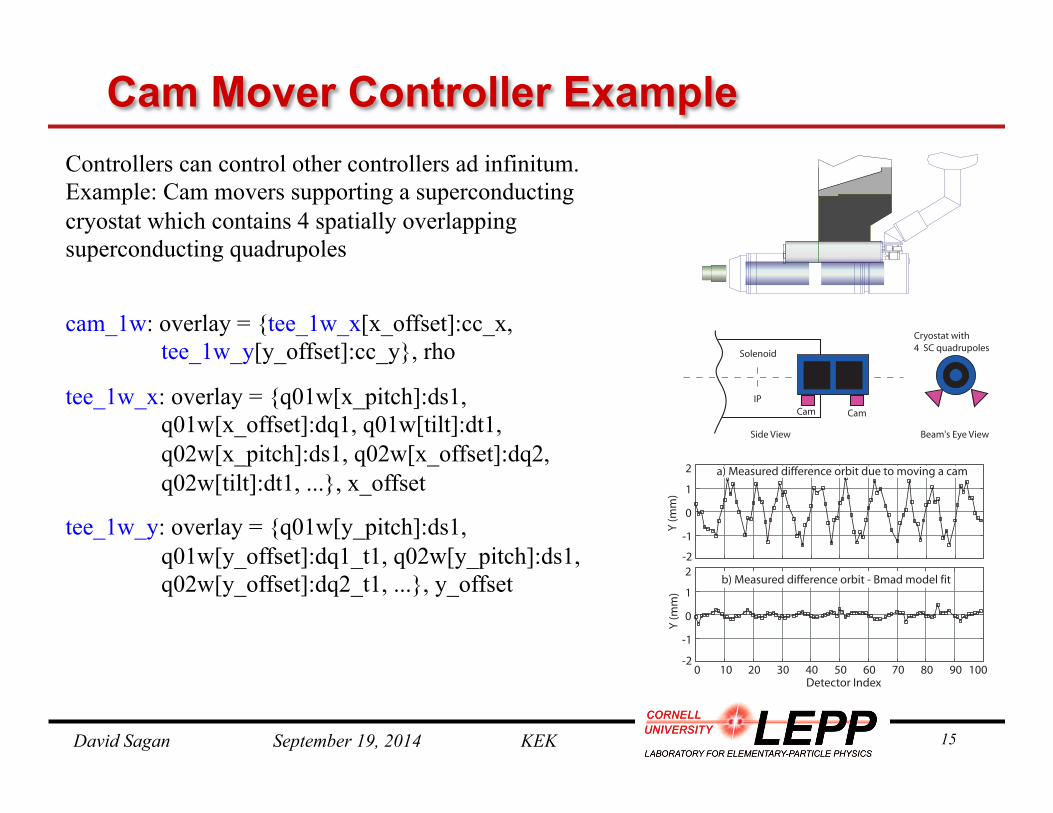
Cam Mover Controller Example Controllers can control other controllers ad infinitum. Example: Cam movers supporting a superconducting cryostat which contains 4 spatially overlapping superconducting quadrupoles cam_1w: overlay = {tee_1w_x[x_offset]:cc_x,
tee_1w_y[y_offset]:cc_y}, rho
tee_1w_x: overlay = {q01w[x_pitch]:ds1, q01w[x_offset]:dq1, q01w[tilt]:dt1,
q02w[x_pitch]:ds1, q02w[x_offset]:dq2, q02w[tilt]:dt1, ...}, x_offset
tee_1w_y: overlay = {q01w[y_pitch]:ds1, q01w[y_offset]:dq1_t1, q02w[y_pitch]:ds1,
q02w[y_offset]:dq2_t1, ...}, y_offset
0 10 20 30 40 50 60 70 80 90 100-2
-1
0
1
2
Y (m
m)
-2
-1
0
1
2
Y (m
m)
Detector Index
a) Measured difference orbit due to moving a cam
b) Measured difference orbit - Bmad model fit
Solenoid
Cryostat with4 SC quadrupoles
IPCam Cam
Beam's Eye ViewSide View

David Sagan September 19, 2014 KEK 16
Bmad, MAD, SAD Lattice Translation MAD-8/MAD-X and Bmad: • ~100% of a MAD lattice can be translated to Bmad. • Not able to translate such things as controller
elements, multipass, etc. from Bmad to MAD. • MAD does not have a wiggler element but a Bmad
wiggler can be approximately converted using a bend-drift-bend model.
SAD and Bmad: • In cooperation with Demin Zhou and Katsunobu
Oide. Translation software from SAD to Bmad has been developed [New 2014!]. • Bmad to SAD translator under development
sher_5764 δ = 0.002
sher_5764 δ = 0.002
[Benchmark run by D. Zhou]
SAD: mult ecsle5 =(l =.01 f1 =.01 fringe =3 sk3=-1.18e-05);
Bmad: ecsle5: sad_mult, f1 = 0.01, fringe_type = sad_full,
l = 0.01, a3 = -1.18e-05 / factorial(3)

David Sagan September 19, 2014 KEK 17
Bmad Ecosystem
Due to its flexibility, Bmad has been used in a number of programs including: • tao General purpose design and simulation. • synrad3d 3D tracking of synch photons,
including reflections, within the beam chamber. • cesrv On-line data taking, simulation, and
machine correction for CESR. • dark_current_tracker Dark current electron
simulation. • freq_map Frequency map analysis. • ibs_sim Analytic intra-beam scattering (IBS)
calculation. • touschek_track Tracking of Touschek particles. • etc...
Code reuse: Modules developed for one program can, via Bmad, be used in other programs.
� �� �� ��
`A`B
XY
Orbit [model]
0
30
60
90
-20
-10
0
10
20
Q00
WQ
01W
Q02
W
SK_Q
03W
Q03
W
SK_Q
04W
Q04
W
SK_Q
05W
Q06
W
Q05
W
SK_Q
06W
� �� �� ��
` A, `
B [m]
Orb
it [m
m]
Beta Function [model]

David Sagan September 19, 2014 KEK 18
Dark Current Tracker Program Problem: Simulate in 3D dark current electrons generated at the walls of the beam chamber. Challenges:
1. Define the beam chamber walls. 2. Be able to track particles that could reverse
direction longitudinally. Solutions: Develop in Bmad
1. X-ray capillary wall code extended for simulating beam chamber walls.
2. Time based tracker module that could handle bi-directional tracking.
Result: A useful program was developed and Bmad gets extended capabilities which have been used in other programs.
Dark current tracks in an RF cavity

David Sagan September 19, 2014 KEK 19
ERL Simulations
One area of current Bmad development is a unified ERL simulation framework. Idea: To be able to simulate • Electrons from the gun cathode to X-ray
generation in wigglers and undulators through to the dump. • X-rays from generation through to the
experimental end stations. x-ray lines
David Sagan September 19, 2014 KEK 20
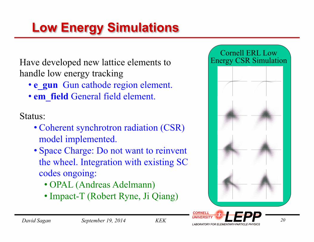
Low Energy Simulations
Have developed new lattice elements to handle low energy tracking • e_gun Gun cathode region element. • em_field General field element.
Status: • Coherent synchrotron radiation (CSR)
model implemented. • Space Charge: Do not want to reinvent
the wheel. Integration with existing SC codes ongoing: • OPAL (Andreas Adelmann) • Impact-T (Robert Ryne, Ji Qiang)
Cornell ERL Low Energy CSR Simulation

David Sagan September 19, 2014 KEK 21
X-Ray Simulation
0 1.0E-4 2.0E-4-2.0E-4-1.0E-40.0
0.5
1.0
-x_pitch (radians)Re
lativ
e In
tens
ity
a) b)
Hns^
FH
^
x_pitch
Photon InPhoton Out
Bragg crystal diffraction simulation
Both incoherent and coherent ray-tracing implemented (but needs more testing). X-ray tracking elements developed: • Crystal ! Bragg & Laue diffraction • Capillary ! Focus X-rays • Mirror • Multilayer Mirror • Diffraction_plate ! Apertures, Zone plates
Status: • Bend, wiggler, and undulator incoherent
X-ray generation implemented. • Coherent X-ray generation from undulators
under development. • First “real world” simulations beginning.
David Sagan September 19, 2014 KEK 22
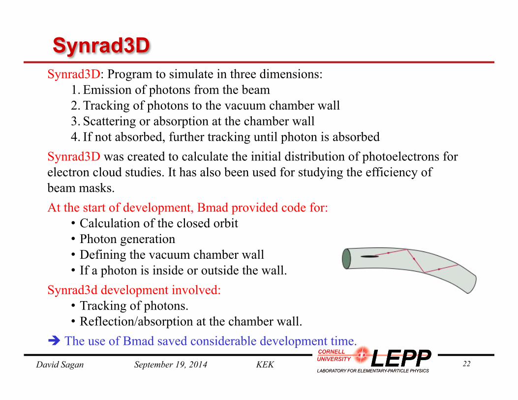
Synrad3D Synrad3D: Program to simulate in three dimensions:
1. Emission of photons from the beam 2. Tracking of photons to the vacuum chamber wall 3. Scattering or absorption at the chamber wall 4. If not absorbed, further tracking until photon is absorbed
Synrad3D was created to calculate the initial distribution of photoelectrons for electron cloud studies. It has also been used for studying the efficiency of beam masks. At the start of development, Bmad provided code for:
• Calculation of the closed orbit • Photon generation • Defining the vacuum chamber wall • If a photon is inside or outside the wall.
Synrad3d development involved: • Tracking of photons. • Reflection/absorption at the chamber wall.
è The use of Bmad saved considerable development time.

David Sagan September 19, 2014 KEK 23
Synrad3d: SuperKEKB Simulation
0
50
100
150
200
250
0 100 200 300 400
EntriesMeanRMS
3599 5.958 3.751
0
50
100
150
200
250
300
350
400
450
0 5 10 15 20
Simulations by Jim Crittenden SuperKEKB wall profile courtesy Takuya Ishibashi
Problem: Photoelectrons can be trapped in the field of a quadrupole. The electrons will react with the beam and if the density is high enough, this can cause problems.
Simulation to determine the number of photons absorbed near a particular quadrupole
EntriesMeanRMS
3521 50.92 75.89
0
100
200
300
400
500
600
700
800
0 200 400
0
25
50
75
100
125
150
175
200
3015.2 3015.3 3015.4 3015.5 3015.6
Photon number
Energy Spectrum # Reflections Angular distribution

David Sagan September 19, 2014 KEK 24
G-2 Experiment
o
pointchamberBeam vacuum
Tangential reference line1.25
Muon orbit
Beam line
Injection
Polarized Muons
Dave Rubin at Cornell has been developing a simulation program to simulate the Muon g-2 experiment at Fermilab Need to simulate:
• Injection line into storage ring. • Three dimensional field of the injection line. • Scattering of muons as they cross the inflector wall • Electrostatic quadrupoles • Muon decay
David Sagan September 19, 2014 KEK 25
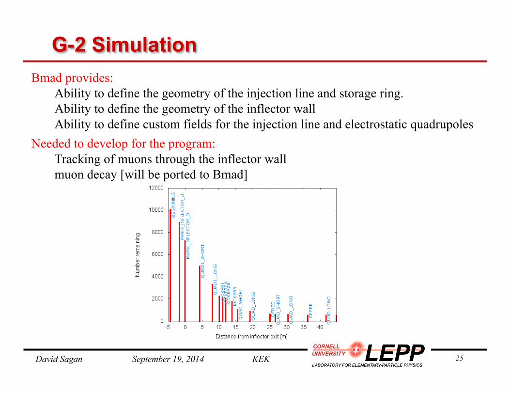
G-2 Simulation Bmad provides:
Ability to define the geometry of the injection line and storage ring. Ability to define the geometry of the inflector wall Ability to define custom fields for the injection line and electrostatic quadrupoles
Needed to develop for the program: Tracking of muons through the inflector wall muon decay [will be ported to Bmad]

David Sagan September 19, 2014 KEK 26
CesrV: Using Bmad in the Control System
CesrV is a online control system program for the e+/e- Cesr ring • Uses Bmad as its calculational engine • Can take orbit, dispersion, betatron phase and coupling measurements • Can correct orbits, dispersion, Twiss parameters, and coupling • Can locate isolated steering, quadrupole, skew quadrupole errors. • Can calibrate steerings, quadrupoles, skew quadrupoles. • Etc. Etc.

David Sagan September 19, 2014 KEK 27
CesrV: Twiss and Coupling Measurement • Shake simultaneously both “a”-mode (horizontal like) and “b”-mode
(vertical like) betatron resonance frequencies. • About 100 detectors in Cesr • Average over 40K turns • Each detector has its own signal processor.
Parallel measurement => Takes about 10 seconds
x
y
Beam response at a detector due to “A”-mode (Horizontal like) shaking
Measurement setup
David Sagan September 19, 2014 KEK 28
In terms of SAD R2: It is convenient to work with Where
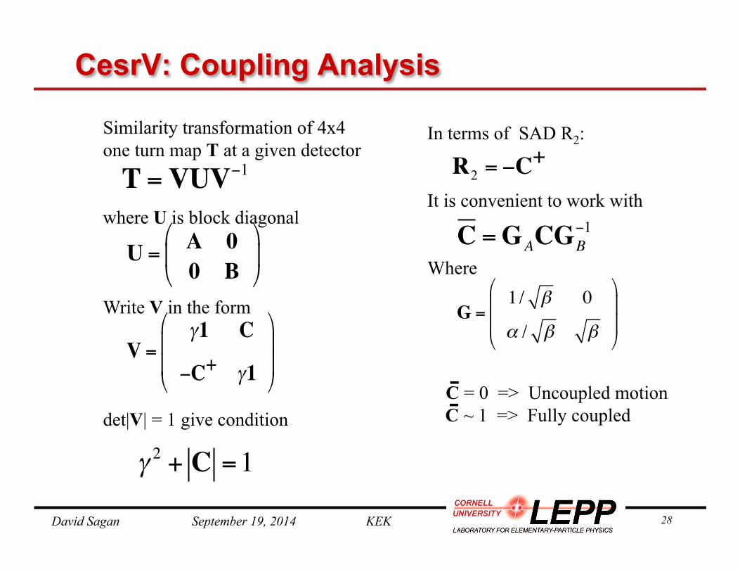
Similarity transformation of 4x4 one turn map T at a given detector where U is block diagonal Write V in the form det|V| = 1 give condition
CesrV: Coupling Analysis
T =VUV−1
U = A 00 B
!
"#
$
%&
V =γ1 C
−C+ γ1
"
#
$$
%
&
''
γ 2 + C =1
C =GACG−1B
G =1/ β 0
α / β β
!
"
##
$
%
&&
C = 0 => Uncoupled motion -
R2 = −C+
C ~ 1 => Fully coupled -

David Sagan September 19, 2014 KEK 29
CesrV: Twiss and Coupling Correction Can measure: βΑ, βΒ, φA, φΒ, C11, C12, and C22 In practice, cleanest is to use: φA, φΒ, C12 Correction calculation takes less than 1 minute
40
0
-40
x (d
eg)
40
0
-40
y (d
eg)
0.2
0
-0.2
160
0
-160
160
0
-160
x/x
(%)
y /
y (%
)C
12
0 20 40 60 80 100
a)
b)
c)
d)
e)
20
0
-20
x (d
eg)
20
0
-20
y (d
eg)
0.1
0
-0.1
20
0
-20
20
0
-20
x/x
(%)
y /
y (%
)C
12
0 20 40 60 80 100
a)
b)
c)
d)
e)
Before correction After correction

David Sagan September 19, 2014 KEK 30
Locating a Skew Quadrupole Error
0 20 40 60 80 100 120 140
0 20 40 60 80 100 120 140
0 20 40 60 80 100 120 140
-0.06
-0.03
0
0.03
0.06
-0.06
-0.03
0
0.03
0.06
-0.06
-0.03
0
0.03
0.06
a)
b)
c)
Detector Index
C12
C12
C12
a region b region
a region
b region

David Sagan September 19, 2014 KEK 31
The Future
Bmad has evolved continually since its birth and shows no sign of slowing down.
Current projects include: • SAD compatibility development. • Further integration with PTC • Undulator coherent X-ray generation. • Testing of partially coherent X-ray tracking. • Nonlinear controllers • ...
David Sagan September 19, 2014 KEK 32
Conclusion
• Bmad has been used successfully at Cornell for a number of years. • With Bmad, new simulation programs can be developed in less time and with less effort. [Caveat: Learning to program with Bmad has a significant learning curve.]
• Bmad is constantly evolving to meet changing needs.
• Collaborations welcome.