Date presented t! L
41
AN ABSTRACT OF THE THESIS OF Oran Lester Albertson for the M. S. in Structural Engineering (Name) (Degree) (Major) Date thesis is presented t! L Title STABILITY OF ELASTICALLY RESTRAINED FRAMED STRUCTURES BY MATRIX ANALYSIS Abstract approved (Major Professor) It has been undertaken here to use the matrix method of structural analysis for the determination of the stability of elastically restrained, simple portal frames. This involves the formulation of the stiffness matrix of the structure in terms of the axial force in the members. The stability criterion, when applied to the stiffness matrix, yields the critical load that may be applied to the structure. The use of this method, when applied to an example frame, yielded results within 0. 1 per cent of a classical approach for the limiting conditions of restraint. These conditions were: (1) no restraint, which produced the side -sway mode of failure and (2) sufficient restraint, which produced the non -sway mode of failure.
Transcript of Date presented t! L

AN ABSTRACT OF THE THESIS OF
Oran Lester Albertson for the M. S. in Structural Engineering (Name) (Degree) (Major)
Date thesis is presented t! L
Title STABILITY OF ELASTICALLY RESTRAINED FRAMED
STRUCTURES BY MATRIX ANALYSIS
Abstract approved (Major Professor)
It has been undertaken here to use the matrix method of
structural analysis for the determination of the stability of elastically
restrained, simple portal frames. This involves the formulation of
the stiffness matrix of the structure in terms of the axial force in the
members. The stability criterion, when applied to the stiffness
matrix, yields the critical load that may be applied to the structure.
The use of this method, when applied to an example frame,
yielded results within 0. 1 per cent of a classical approach for the
limiting conditions of restraint. These conditions were: (1) no
restraint, which produced the side -sway mode of failure and (2)
sufficient restraint, which produced the non -sway mode of failure.

STABILITY OF ELASTICALLY RESTRAINED FRAMED
STRUCTURES BY MATRIX ANALYSIS
by
ORAN LESTER ALBERTSON
A THESIS
submitted to
OREGON STATE UNIVERSITY
in partial fulfillment of
the requirements for the
degree of
MASTER OF SCIENCE
June 1966
APPROVED:
Associate Professor of Civil Engineering
In Charge of Major
Head of Department of Civil Engineering
Dean of Graduate School
Date thesis is presented ii
Typed by Arlene L. Kampe
ACKNOWLEDGMENTS
The author wishes to express appreciation for the assistance
and financial support of the following persons and organizations: The
National Science Foundation for financial support through National
Science Foundation Graduate Engineering Stipend Number 965 and the
staff of the Oregon State University Statistics Computing Laboratory
for their suggestions and assistance on the computer program.
Special thanks to Dr. H. I, Laursen for his suggestions on the
area of study, for his recommendations throughout the investigation,
and for his time and encouragement.
Also special thanks to my wife, Barbara, for her moral
and financial support throughout the year.

TABLE OF CONTENTS
INTRODUCTION
METHOD OF ANALYSIS
1
Notation Used 2
Displacement Transformation Matrix 4
Member Stiffness Matrix 7
Structure Stiffness Matrix 9
Stability Criterion 10
APPLICATION TO ELASTICALLY RESTRAINED STRUCTURE 10
Development of Required Matrices 10
Pinned -Base Frame 10
Fixed -Base Frame 14
Application of Stability Criterion 16
COMPUTER PROGRAM DESCRIPTION 17
Computer Logic 17
Program Generalities 18
RESULTS 19
Presentation 19
Input 19
Output 20
Reliability 20
CONCLUSIONS 22
BIBLIOGRAPHY 23
2
APPENDIX 26
Notation Used
List of Variables Used in Programs
Program Listing
27
29
31

LIST OF FIGURES AND TABLE
Figure Page
1. External Load and Displacement Notation 3
2. Internal Load and Displacement Notation 3
3. Typical Framed Structure 5
4. Notation, Geometry and Loading of Pinned -Base Frame 11
5. Deflected Structure 11
6. Lambda vs.. Spring Constant of the Restraint 21
Table
1. Sample Output Data 20
STABILITY OF ELASTICALLY RESTRAINED FRAMED
STRUCTURES BY MATRIX ANALYSIS
INTRODUCTION
In the design of structures it is necessary to know the load
carrying capability of the structure as governed by its stability.
Since Euler' s development of the column formula, stability has been
a point of concern in structures containing columns.
The critical loads as applied to simple portal frames have
been found, in general, for both the symmetrical (non -sway) mode
of failure and the antisymmetrical (sidesway) mode of failure
(2, p. 251-255, 23, p. 66, 1 49). It is undertaken here to use a
method applicable to a large variety of framed structures (12) to
determine the critical loads of elastically restrained, simple portal
frames. By varying the stiffness of the restraint, the critical
loads will vary from those obtained for the sidesway - permitted
condition to those obtained for the non -sway condition.
The following limitations or assumptions are made in regard
to this investigation:
1. The stresses in the members remain in the elastic
range.
2. Only plane frameworks will be considered.
3. There are no out -of -plane deformations.

4. The moment of inertia is constant along the length of
each member.
5. Each column is initially perfectly straight.
6. Each column is centrally loaded.
7. Placement of the loads will be such that there will be
no primary bending moments.
METHOD OF ANALYSIS
2
The method of analysis to be used is the displacement method
of matrix analysis. The development of this method can be credited
mainly to those engaged in aircraft analysis and design (1, 9, 24).
To analyze the highly redundant structures used in the aircraft
industry by classical methods involves the simultaneous solution of
a large number of linear equations. Matrix notation is ideal in such
a situation because of its concise notation and its ability to be readily
applied to a digital computer.
Notation Used
Figure 1(a) shows the external coordinate system to be used.
External displacements are denoted by D and external loads are
denoted by Q as shown in Figure 1(b). Quantities as shown are
considered to be positive. The circled numbers refer to nodal point
designation. External loads will be applied only at the nodal points.

3
Each member is designated by the number near the center of each
member span.
(a) (b)
Figure 1. External Load and Displacement Notation
Superscripts used on external loads and displacements denote
the particular component as shown in Figure 1(a), Subscripts used
on external loads and displacements refer to the nodal point at which
they occur. For example in Figure 1 (b) , Q2 refers to a clockwise
moment applied at nodal point number two.
Y
(a)
X
(b)
Figure 2. Internal Load and Displacement Notation
(c)
Figure 2(a) shows the member coordinate system. Figure
2(b) shows the internal or member loads where P refers to the
axial load, M refers to the bending moment, and V refers to the
2 D
a D 1
2
i X' ,P T
L
Pt
4
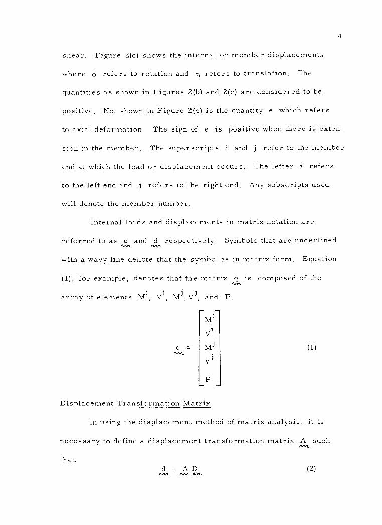
shear. Figure 2(c) shows the internal or member displacements
where 4, refers to rotation and y refers to translation. The
quantities as shown in Figures 2(b) and 2(c) are considered to be
positive. Not shown in Figure 2(c) is the quantity e which refers
to axial deformation. The sign of e is positive when there is exten-
sion in the member. The superscripts i and j refer to the member
end at which the load or displacement occurs. The letter i refers
to the left end and j refers to the right end. Any subscripts used
will denote the member number.
Internal loads and displacements in matrix notation are
referred to as q and d respectively. Symbols that are underlined nnn
with a wavy line denote that the symbol is in matrix form. Equation
(1), for example, denotes that the matrix q is composed of the nnti
array of elements M1, V1, M3, V3, and P.
q =
P
(1)
Displacement Transformation Matrix
In using the displacement method of matrix analysis, it is
necessary to define a displacement transformation matrix A such Nt
that: d = A D
AAA AAA (2)
nn
i M
V
Mi
Vi
.nn.

2 2 D1
3 D2 /D 3
2 1 L ' r 1
D
2
L
L
Figure 3. Typical Framed Structure
For example, in Figure 3, neglecting axial deformations
and noting that D2 D 2
= O. 0 and that D1 = D 2 we may rewrite
equation (2) and get:
1 J
J
r l
i 11 2
11)J 2
2
i
CI) 3
i
rl 3
J
J 113
0
0
0
-1
0
0
0
0
0
0
0
-1
0
0
1
0
1
0
0
0
0
0
0
0
0
0
0
0
0
0
1
0
0
0
1
0
0
0
0
0
0
0
0
0
1
0
0
0
1
= D1
2
D1
D3 2
D3 3
(3)
5
'4)1
43
=
Di

6
Equation (3) may be rewritten in a more usable form by
combining terms and by dividing by L, where needed, to make the
matrix dimensionally homogeneous, If this is done we obtain:
`P'1
`rJ i j
r,l ril
_-
L
4) 2 i j
T12 T12
L
4)3
i 3
i j 113 113
L
o o o o
o 1 o o
1 0 0 0
o 1 o o
o o 1 o
o 0 o o
o 0 0 1
o 0 1 o
1 o o 0
(4)
Di/L=D2/L
D3 1
D3 D 2
D3 3
If axial deformations only were being considered the displace-
ment transformation matrix would be as shown in equation (5).
e
e
1
2
e3
0 1 0 0
-1 0 1 0
0 0 0 1
D1
D2 1
D1 2
D2 2
Such a transformation is used most often in the truss type of
structures.
(5)
1)2

7
Member Stiffness Matrix
The stiffness of a member is defined as the amount of force
required to deflect the member a unit distance. It is usually
expressed by a ratio as in equation (6):
k = P/ e (6)
where k is the stiffness of the member, P is the force applied,
and e is the amount of deflection, Equation (6) can be rearranged
and expressed in our matrix notation as:
q = k, d nnn ,,N-
(7)
where k, is the individual member stiffness matrix. Thus the i AAA..
expression for the axial force on an elastic restraint or spring
become s:
P = k e sp
where k denotes the stiffness of the spring, sp
(8)
Considering axial force P, the differential equation for
bending is:
4 2
EId 4+ P d
2 dx dx = 0
Using the general solution of this differential equation and the
(9)
force and deflection boundary conditions, it can be shown that (12)

where:
M1 k1 k2 k3
Mi EI k2 k1 k3 L
VL k3 k3 k4
(10)
k k (s - c) (11a) 1 2-2c-ks
- s) ( llb)
k2 2-2c- s
k k 2(c - 1) (11c)
3 2-2c- s
3s (11d) k4 2 - 2c - s
s = sink (11e)
c = cos k
2 PL2 EI
(11f)
(11g)
If P is a tensile force the expressions in equations (11)
are replaced by:
k (Ac - s) 1 2-2c+ks
K(s - K) k2 2-2c+Ks
A 2(c - 1)
k3 2-2c+Ks
A 3T
k4 2-2c+Ks
(12a)
(12b)
(12c)
(12d)
8
k
i (1)
J L
(k
k
k
k
=
9
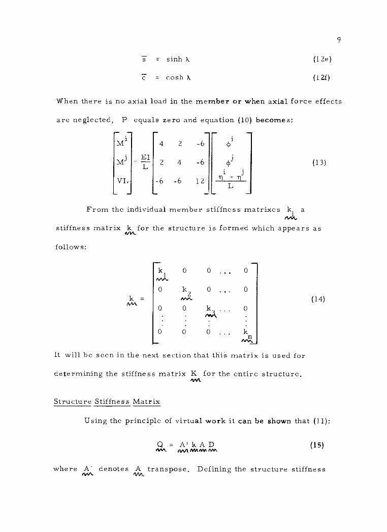
s = sinh (12e)
= cosh k (12f)
When there is no axial load in the member or when axial force effects
are neglected, P equals zero and equation (10) becomes:
i M
Mi
VL
EI L
4
2
-6
2
4
-6
-6
-6
12
i el)
i T1
- j (13)
L
From the individual member stiffness matrixes k. a nniV
stiffness matrix k for the structure is formed which appears as Ann.
follows:
k nM
k1 nnti
0
0
0
0
k2 Anti
0
0
0
0
0 ..,
0
0
kn tvvs.
(14)
It will be seen in the next section that this matrix is used for
determining the stiffness matrix K for the entire structure, nrvt.
Structure Stiffness Matrix
Using the principle of virtual work it can be shown that (11):
Q A' k A D Nv.. (IAA MA AM Nh (15)
where A' denotes A
transpose, Defining the structure stiffness
$
=
=
c
0
4%'

matrix as
Ann - Ann Ann Anti (16)
10
it is seen that the external displacements are related to the external
loads by the expression
Q = K D n nM. nnti (17)
Stability Criterion
When the load applied to a structure reaches the critical
load (that load which will make the structure unstable) its deflection
grows infinitely large with virtually no increase in load, From
equation (17) the only way D can change considerably with no
change in Q is for the determinant of K to go to zero (19, 21), nom. If the determinant of K equals zero, the structure is said to be in
neutral equilibrium and the critical load P may be calculated, cr
APPLICATION TO ELASTICALLY RESTRAINED STRUCTURE
The application of the matrix method to a particular structure
requires that the previously mentioned A and k matrices be MA. AAA-
developed for the structure, From these the K matrix for the AAA,
structure can be determined,
Development of Required Matrices
Pinned -Base Frame, The notation, geometry, and loading of
a pinned -base frame is shown in Figure 4, The lengths and moments
K A
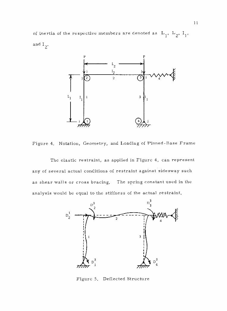
of inertia of the respective members are denoted as L1, L2, I
and I2.
L1
L2
I2
P
1
2
3
11
Figure 4. Notation, Geometry, and Loading of Pinned -Base Frame
The elastic restraint, as applied in Figure 4, can represent
any of several actual conditions of restraint against side sway such
as shear walls or cross bracing. The spring constant used in the
analysis would be equal to the stiffness of the actual restraint.
1 D2
3
D3 D3 2
Figure 5. Deflected Structure
12
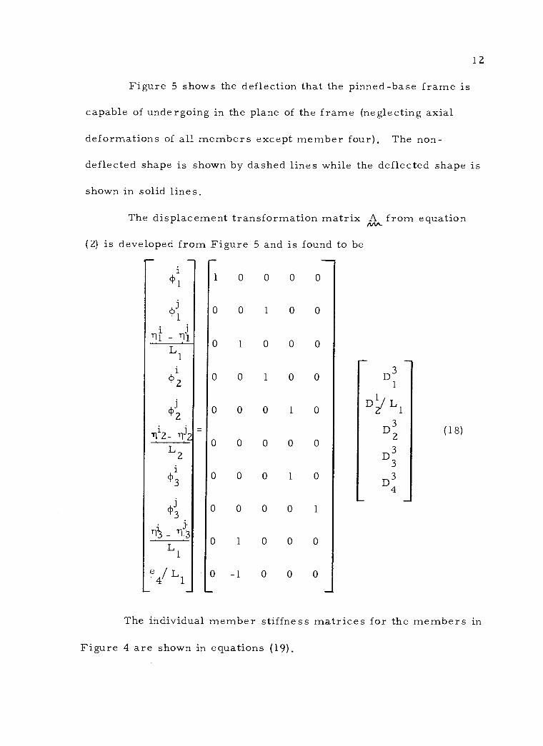
Figure 5 shows the deflection that the pinned -base frame is
capable of undergoing in the plane of the frame (neglecting axial
deformations of all members except member four). The non -
deflected shape is shown by dashed lines while the deflected shape is
shown in solid lines.
The displacement transformation matrix A from equation
(2) is developed from Figure 5 and is found to be
i (1)1
1 0 0 0 0
0 0 1 0 0
0 1 0 0 0
0 0 1 0 0 D3 1
0 0 0 1 0 D L1
0 0 0 0 0
D3 2
(18)
D3 3
0 0 0 1 0 D3
4
0 0 0 0 1
0 1 0 0 0
0 -1 0 0 0
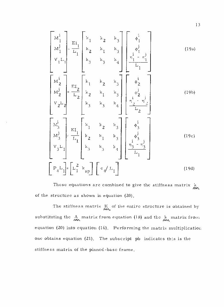
The individual member stiffness matrices for the members in
Figure 4 are shown in equations (19).
TI1-T11 L1
i
<1,2
<Vl 2
T112- r112
L2
$1 3
-03 L
1
e4 L1
13
i M1
j Ml
V i L
L - M1
2
Mi 2
V2 L2
i M3
M3
V3L1 3 1
[P4L}[L2
EI 1
kl
k2
k3
- kl
k2
k3
kl
k2
k3
ksp
k2 k3
kl k3
k3 k4
k2 k3
kl k3
k3 k4
k2 k3
kl k3
k3 k4
[e/Ll
`1)1
- j
l 1
(19a)
(19b)
(19c)
(19d)
EI2
L1
i
1:13' 2
71z
L2
EI 1
L2
'1)3
i j T13 T13
L1
L1 1
These equations are combined to give the stiffness matrix k nnrt
of the structure as shown in equation (20),
The stiffness matrix K of the entire structure is obtained by
substituting the A matrix from equation (18) and the k matrix from N equation (20) into equation (16). Performing the matrix multiplication
one obtains equation (21). The subscript pb indicates this is the
stiffness matrix of the pinned -base frame.
1
2 1
i ¢1
i -
z
_
2
.4)3
Ann_
nnn
1 L1
1 2 3
1
"2

i M1 k1 k2 k3
Ml k2 kl k3
VL1 k3 k,l k4
M2 4 2
M2 EI1 LlI2
2 4 -6 L2I1
V .2L2 L
6 -6 12
I_Mi J
k1 k2 k3
M3 k2 k1 k3
V3L1 k3 k3 k4
P4L1
EI K = 1
AA"- L
1
L3k 1 sp
\
EI1
k 1
k3 k2 0
3
L1ksp k3 2k41 k3 k3
I2Ll I2L1 k2 k3 k1+411L2 2
1 1 2 L
1
0 k3 2I2L1 1+4I2L1 1 2 1 2
0 k3 0 k2
4 /L1
0
k3
0
k2
kl
14
20)
(21)
Fixed -Base Frame. The fixed -base frame considered has the
same form as Figures 4 and 5 except that nodal points one and four
are fixed and cannot, therefore, undergo rotation. The displacement
2
3
1 2
-6 1
1
(i)
i .
- 1 1 L1
i
(1)2
2 i j
- 2 1 2
r-
LZ
3 i
3 -3
L 1
I
2
/
q>3
1

15
transformation matrix in this case is the same as the three middle
columns of the A matrix for the pinned -base frame. ewe.
o 0 0
o 1 0
1 0 0
o 1 0
o 0 1
A =
o 0 0 (22)
o o 1
o o o
1 o o
-1 0 0
The stiffness matrix k of the structure is the same as for .w",
the pinned -base frame. This matrix is given by equation (20).
Performing the necessary matrix operations the stiffness matrix K
for the entire structure becomes
EI K =
nññ. L
1
L3k 1 sp
2k4 + k3 k3
I2L1 I2L1 k3 k1 2 +4
I2L1 I2L1 k3 2 k
I +4
1L2 I1L2
(23)
...".
I1L2 I1L2
1
4 EI1
I
16
The subscript fb denotes this is the stiffness matrix of the fixed-
base frame.
Application of Stability Criterion
As previously mentioned, the criterion for neutral equilibrium
is that the determinant of K is equal to zero. In observing the
composition of the K matrices from equations (21), (23), and (11),
it is seen that the condition for the determinant is best obtained by
a trial and error solution.
The procedure used is as follows: first, a value for A is
assumed; the sines and cosines of ? are then obtained; these are
then substituted into the equations for kl, k2, k3, and k4, which
in turn are substituted into the expression for the determinant of K. A If the determinant of K is zero, the appropriate value of P is
rv+n. cr
calculated from the assumed value of X . If the determinant of K is
positive or negative, a larger or smaller value, respectively, of X.
is assumed and the determinant is recalculated.
This procedure may take a large number of trials before a
value of X. can be found which will make the determinant of K
equal
to zero, A high -speed digital computer can be used very effectively
to perform the required calculations.
iw.
17
COMPUTER PROGRAM DESCRIPTION
The program used was written in the FORTRAN language
for use on an IBM 1410 Data Processing System. The examples were
run at the Oregon State University Statistics Computing Laboratory.
Computer Logic
The program was written in three parts - -the main program
with two subprograms. Complete listings will be found in the
Appendix. The first subprogram (SUBROUTINE MSTFM) simply
assembles the member stiffness matrix of the structure from the
values given it by the main program, This matrix is then returned
to the main program for future calculations,
The second subprogram (FUNCTION DETERM) calculates the
value of the determinant of any square matrix given it by the main
program.
A brief description of the main program logic follows:
1. All necessary input variables, such as frame geometry,
accuracy desired, and the displacement transformation
matrix are input to the computer.
2, An initial value of k is assumed.
3 The SUBROUTINE MSTFM forms the member stiffness
matrix from the given geometry and the assumed value of N..
18
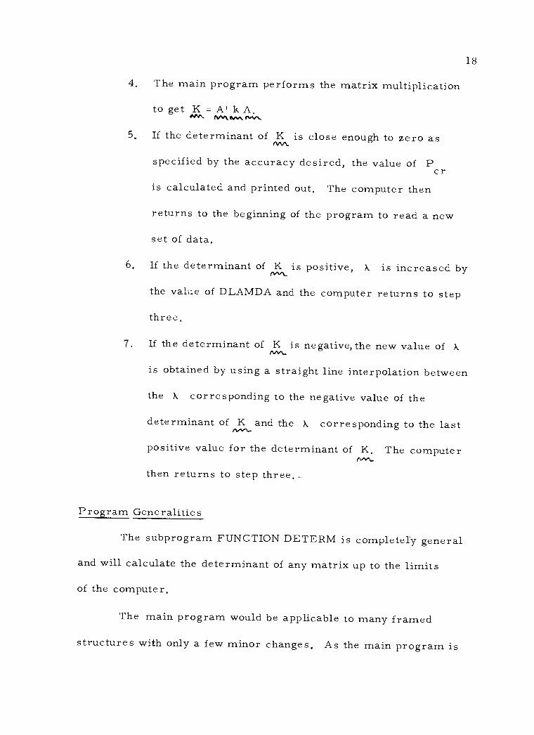
4. The main program performs the matrix multiplication
to get K =A'kA. met aM n"n
5. If the determinant of K is close enough to zero as rw specified by the accuracy desired, the value of P cr is calculated and printed out. The computer then
returns to the beginning of the program to read a new
set of data.
6. If the determinant of K is positive, k is increased by rwL
the value of DLAMDA and the computer returns to step
three,
7. If the determinant of K is negative, the new value of . non_
is obtained by using a straight line interpolation between
the k corresponding to the negative value of the
determinant of K and the k corresponding to the last
positive value for the determinant of K. The computer 1%."\.,
then returns to step three..
Program Generalities
The subprogram FUNCTION DETERM is completely general
and will calculate the determinant of any matrix up to the limits
of the computer.
The main program would be applicable to many framed
structures with only a few minor changes. As the main program is
nM_

19
listed in the Appendix it is limited to a symmetric, three -member,
framed structure with a single elastic restraint.
The subprogram SUBROUTINE MSTFM was written
specifically for the structure configuration used in this work.
RESULTS
Presentation
Input. The examples calculated in this work are based on
both a pinned -base frame and a fixed -base frame. The properties
of the members selected for the calculations, using the notation of
Figure 4, are L1 = 20 feet, L2 = 40 feet, I1 = 1000 in4, and I2 =
500 in4, In each case Young's modulus is equal to 30, 000 kips per
square inch.
The degree of accuracy to which the determinant of K was
to equal zero was dependent upon the magnitude of the determinant of
K for X. equal to zero and also upon the value input to the computer nnr`
as data. The accuracy used was equal to the product of the input
accuracy, equal to unity in all examples calculated, and 0.01 per
cent of the determinant of K for k equal to zero. Hike+..
The value of the increment of X. DLAMDA, was varied
with the stiffness of the restraint to obtain fast convergence of the
determinant of K to zero.
,
20
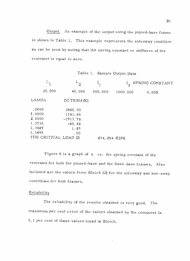
Output. An example of the output using the pinned -base frame
is shown in Table 1. This example represents the sidesway condition
as can be seen by noting that the spring constant or stiffness of the
restraint is equal to zero.
Table 1, Sample Output Data
L1 L2 I1 I2 SPRING CONSTANT
20, 000 40, 000 500. 000 1000, 000 0, 000
LAMDA
.0000
DETERM(K)
2880. 00 1. 0000 1141, 46 2. 0000 -1913. 78 1, 3736 -80. 48 1, 3489 1. 85 1, 3495 . 00 THE CRITICAL LOAD IS 474. 294 KIPS
Figure 6 is a graph of X. vs. the spring constant of the
restraint for both the pinned -base and the fixed -base frames, Also
included are the values from Bleich (2) for the sidesway and non -sway
conditions for both frames,
Reliability
The reliability of the results obtained is very good, The
maximum per cent error of the values obtained by the computer is
0, 1 per cent of those values found in Bleich.

6
5
4
cd 3 p
2
1
0
FIXED -BASE FRAME
HINGED -BASE FRAME >
r
O CALCULATED
4 X FROM BLEICH
A\IY STIFFNESS LARGE ENOUGH TO PREVENT SIDESWAY .i........ 0 10 20 30 50
Spring constant of the restraint, kips /in
Figure 6. Lambda vs. Spring Constant of the Restraint
2 100
C

22
Although there are a large number of calculations involved,
round -off error does not seem to be a problem within the accuracy
desired. This assumption was substantiated by the calculation of one
set of data using double precision arithmetic. This calculation showed
no change in the sixth significant figure.
CONCLUSIONS
The method presented in this work is a method that shows
good accuracy for simple portal frames. The method is versatile
and can be applied to many types of framed structures. Framed
structures with elastic restraints are especially suited for analysis
by the use of this method.

23
BIBLIOGRAPHY
1. Argyris, John Haydie. Energy theorems and structural analysis. London, Butterworths, 1960. 85 p.
2. Bleich, Friedrich. Buckling strength of metal structures. New York, McGraw -Hill, 1952. 508 p.
3 Clough, Ray W. Matrix analysis of beams. Proceedings of the American Society of Civil Engineers 84(EM1): 1 -24. Jan. 1958. (Paper no, 1494)
4. . Use of modern computers in structural analysis. Proceedings of the Society of Civil Engineers 84(ST3): 1 -20, May 1958. (Paper no. 1636)
5. Denke, P. H. A matric method of structural analysis. Pro- ceedings of the Second U.S. National Congress of Applied Mechanics, 1955, pp. 445 -451.
6, Hoff, Nicholas John, The analysis of structures, New York, Wiley, 1956. 493 p,
7, Hunt, P. M. The electronic digital computer in aircraft structural analysis. Aircraft Engineering 28:70 -76, 111 -118, 155 -165, 1956.
8, James, Benjamin Wylie. Principal effects of axial load on moment distribution analysis of rigid structures. National Advisory Committee for Aeronautics, Technical Note no 534. July 1935, 58 p.
9. Langfors, Börje, Analysis of elastic structures by matrix transformation with special regard to semimonocoque structures. Journal of the Aeronautical Sciences 19:451 -458. 1952.
10. . Matrix methods for redundant structures, Journal of the Aeronautical Sciences 20:292 -293. 1953.
11, Laursen, Harold I. Associate Professor of Civil Engineering, Oregon State University. Matrix analysis of structures. Mimeo- graphed lecture notes,

24
12. Laursen, Harold I. Stability and non -linear analysis of frame structures. Berkeley, 1963. 80 numb, leaves. (University of California. Department of Civil Engineering, Structure and Materials Research Report No. 63 -4 on National Science Founda- tion Research Grant G18986).
13. Livesly, R. K. Analysis of rigid frames by an electric digital computer. Engineering 176:230 -233, 277 -278. 1953.
14. et al. Analysis of rigid -jointed plane frame- works. Engineering 177: 239 -241. 1954.
15. Lu, Le -Wu. Stability of frames under primary bending moments. Proceedings of the American Society of Civil Engineers 89(ST3): 35 -62. June 1963. (Paper no. 3547)
16. Lundquist, Eugene E. A method of estimating the critical buckling load for structural members. National Advisory Committee for Aeronautics. Technical Note no, 717. 36 p.
17. . Stability of structural members under axial load. National Advisory Committee for Aeronautics, Technical Note no, 617. Oct. 1937. 29 p.
18. Masur, E. F. , I. C. Chang and L. H. Donnell. Stability of frames in the presence of primary bending moments. Proceed- ings of the American Society of Civil Engineers 87 (EM4): 19 -34. Aug. 1961. (Paper no. 2882)
19. McMinn, S. J. The determination of the critical loads of plane frames. The Structural Engineer 39:221-227. 1961.
20. Niles, Alfred S. and Joseph S. Newell. Airplane structures, 3d ed. Vol. II New York, Wiley, 1943. 439 p.
21, Renton, John D. Stability of space frames by computer analysis. Proceedings of the American Society of Civil Engineers 88(ST4): 81-103. Aug. 1962. (Paper no. 3237)
22. Sokolnikoff, I. S. Mathematical theory of elasticity. 2d ed. New York, McGraw -Hill, 1956. 476 p.
23. Timoshenko, Stephen P. and James M. Gere, Theory of elastic stability. 2d ed, New York, McGraw -Hill, 1961, 541 p.

25
24. Wehle, L. B., Jr. and Warner Lansing. A method for reducing the analysis of complex redundant structures to a routine proce- dure. Journal of the Aeronautical Sciences 19:677-684. 1952.
25. Williams, D. Development in the structural approach to aero- elastic problems, Aircraft Engineering 26:303 -307, 1954,

26
APPENDIX
27
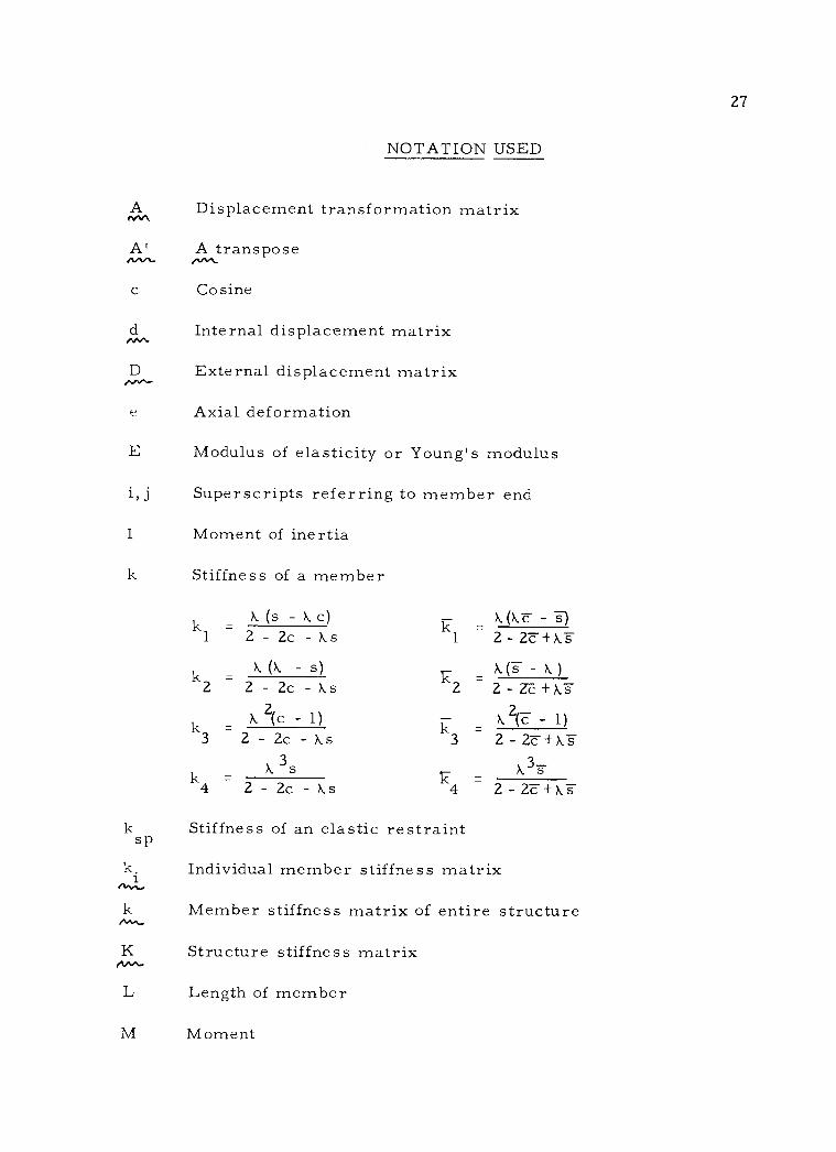
NOTATION USED
A Displacement transformation matrix
A' A transpose
c Cosine
d Internal displacement matrix
D External displacement matrix
e Axial deformation
E Modulus of elasticity or Young's modulus
i, j Superscripts referring to member end
I Moment of inertia
k Stiffness of a member
(s - c) k (1,:c - 1 2 - 2c -ks 1 2-2c+s
., k (X. - s) k (s - A)
Z 2 - 2c - ks 2 2-Zc+X.s
k =k 2(c - 1) k k 2(c - 1)
3 2- 2c - As 3 2- 2c +X.s
k X. k k3s
4 2 - 2c -ks 4 2-2c+X.s
k Stiffness of an elastic restraint sp
k. Individual member stiffness matrix i
k Member stiffness matrix of entire structure nN..
K Structure stiffness matrix nM-
L Length of member
M Moment
.w.- "nn,
rm..
k
3s
A
k
_

P Axial force
P Critical axial force cr
q Internal load matrix
Q External load matrix
s Sine
Shear
x, y Individual member coordinates
11 Translation of end of member
(i)
2 PL2 k EI
Rotation of end of member
28
µ

29 LIST OF VARIABLES USED IN PROGRAMS
Main Program
A Displacement transformation matrix
ACC Accuracy to which determinant of BGK must approach zero. Value input is multiplied by 0.01 per cent of the determinant of BGK for . = 0 to get the actual accuracy.
BGK Structure stiffness matrix
CRDEND Routine to test for last data card
DETERM Subprogram to' evaluate the determinant of BGK
DLAMDA Increment
E Young's modulus in ksi
FI1,FI2 Moment of inertia -- corresponds to I1,I2 in in
FL1, FL2 Length -- corresponds to L1, L2 in feet
M Size of SMK matrix
MSTFM Subroutine to form SMK
N Degrees of freedom
4
NTEST, Temporary values to insure program convergence. NCOUNT If more than 20 increments of A are required, the
program will switch to the next set of data,
PR Value of the determinant of BGK
SMK Member stiffness matrix of the entire structure
SPRK Spring constant or stiffness of restraint in kips/ in
TEMP Temporary storage
TPR, PPR, TVL, PPL Temporary values to speed program convergence
VLAMDA
cf }
t
30
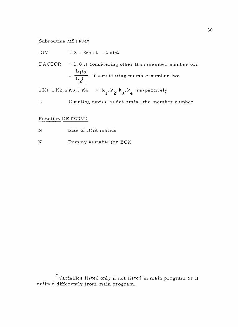
Subroutine MSTFM*
DIV = 2 - 2cos - k sink
FACTOR = 1. 0 if considering other than member number two L1I2
if considering member number two L2I1
FK 1, FK2, FK3, K4 = k1, k2, k3, k4 respectively
L Counting device to determine the member number
Function DE TERM*
N Size of BGK matrix
X Dummy variable for BGK
Variables listed only if not listed in main program or if defined differently from main program.
=
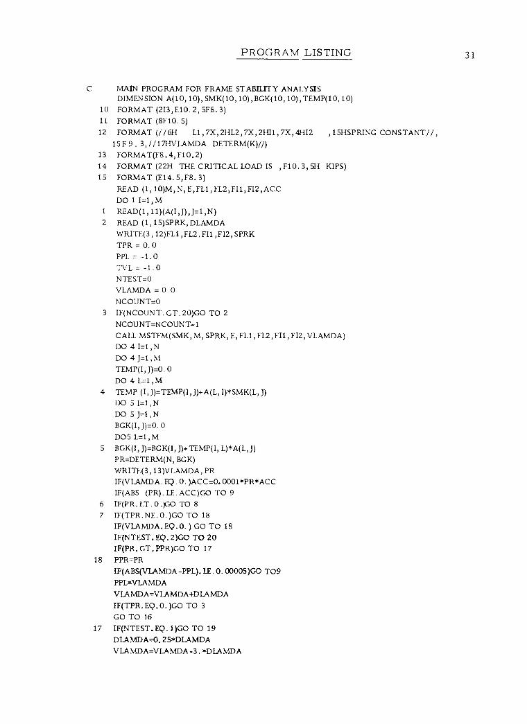
PROGRAM LISTING
C MAIN PROGRAM FOR FRAME STABILITY ANALYSIS DIMENSION A(10, 10), SMK(10, 10),BGK(10, 10) , TEMP(10, 10)
10 FORMAT (2I3,E10.2, SF8. 3)
11 FORMAT (8F10.5) 12 FORMAT (//6H L1 , 7X, 2HL2, 7X, 2HI1, 7X, 4HI2 ,ISHSP RING CONSTANT//,
15F 9 . 3, / / 17HV LAMDA DETERM(K)//) 13 FORMAT(F8.4, F10.2) 14 FORMAT (22H THE CRITICAL LOAD IS , F10.3, 5H KIPS) 15 FORMAT (E14. 5, F8. 3)
READ (1,10)M,N,E,FL1,FL2,FI1,FI2,ACC DO 1 I=1,M
1 READ(1, 11)(A(I,J),J=1,N) 2 READ (1, 15)SPRK, DLAMDA
WRITE(3, 12)FL1,FL2, FI1 , FI2, SPRK
TPR = O. 0
PPL = -1.0 TVL= -1.0 NTEST=O VLAMDA = 0.0 NCOUNT=O
3 IF(NCOUNT. GT.20)GO TO 2
NCOUNT=NCOUNT+1 CALL MSTFM(SMK, M, SPRK, E, FL1, FL2, FI1, FI2, VLAMDA)
DO 4I=1,N DO 4 J=1 , M
TEMP(I, J)=0. 0
DO 4 L=1, M
4 TEMP (I, J)=TEMP(I, J)+A(L, I)*SMK(L, J)
DO 5 I=1 ,N
DO 5 J=1 ,N BGK(I, J)=0. 0
DO5 L=1,M S BGK(I, J)=BGK(I, J)+TEMP(I, L)*A(L, J)
PR=DETERM(N, BGK)
WRITE(3, 13)VLAMDA, PR IF(V LAMDA. EQ . 0. )ACC=O. 0001*PR*ACC IF(ABS (PR). LE. ACC)GO TO 9
6 IF(PR_ LT. 0 .)GO TO 8
7 IF( TPR. NE. O. )GO TO 18
IF(VLAMDA. EQ. O. ) GO TO 18
IF(NTEST, EQ. 2)GO TO 20 IF(PR. GT. PPR)GO TO 17
18 PPR=PR
IF(ABS(VLAMDA -PPL). LE. O. 0000S)GO TO9 PPL=VLAMDA
VLAMDA=VLAMDA+DLAMDA
IF(TPR.EQ.O. )GO TO 3
GOTO16 17 IF(NTEST. EQ. 1)GO TO 19
DLAMDA=0, 25*DLAMDA
VLA MDA=VLAMDA -3. *DLAMDA
31
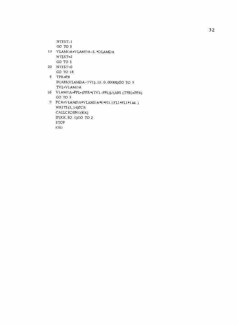
32
NTEST=1 GO TO 3
19 V LAMDA=V LAMDA-5 . *D IAMDA NTEST=2 GO TO 3
20 NTEST=O GO TO 18
8 TPR=PR
IF(ABS(VLAMDA-TVL). LE. 0. 00005)GO TO 9
TV L=V LAMDA 16 VLAMDA=PPL+(PPR*(TVL-PPL))/(ABS (TPR)+PPR)
GO TO 3
9 PCR=VLAMDA*VLAMDA*E*FI1/(FL1*FL1*144. ) WRITE(3, 14)PCR CALLCRDEND(KK)
IF(KK. EQ. 1)GO TO 2
STOP
END

33
SUBROUTINE MSTFM(SMK, M, SPRK, E, FL1 , FL2, FIl , FI2, V LAMDA) DIMENSION SMK(10, 10)
DO 1 I=1, M
DO 1 J=1,M 1 SMK(I, J)=0. 0
7 FK1=4. FK2 = 2. FK3 = -6. FK4=12. L=3
FACTOR=(FL1*FI2)/(FL2*FI1) GOT05
3 IF(V LAMDA. EQ . O. )GO TO 9
8 DIV=2. 0-2. *COS (VLAMDA) -V LAMDA*SIN (VLAMDA) FK1=(VLAMDA*(SIN (VLAMDA)-VLAMDA*COS (VLAMDA)))/DIV FK2=(VLAMDA*(VLAMDA-SIN (VLAMDA)))/DIV FK3=(VLAMDA*VLAMDA*(COS (VLAMDA) -1. 0)) /DIV FK4=(VIAMDA*VLAMDA*VI,AMDA*SIN (VLAMDA))/DIV
9 L=-6 INCL=6
4 FACTOR = 1.0 2 L=L+INC
5 SMK(L+1, L+1 FK1 *FAC TOR SMK(L+1, L+2)4K2*FAC TOR SMK(L+1 , L+30K3*FACTOR SMK(L+2, L+1)4'K2*FACTOR SMK(L+2, L+2)=FK1 *FAC TOR SMK(L+2, L+ 3)=FK3*FAC TOR SMK(L+3, L+1)=-FK3*FACTOR SMK(L+3, L+2)=FK3*FAC TOR SMK(L+3 , L+3)=FK4*FAC TO R IF(L. EQ . 3)GO TO 3
IF(L. LT. 6)GO TO 2
6 SMK(M, M)+(FL1*FL1*FL1*SPRK*1728. )/(E*FI1) RETURN END

34
FUNCTION DETERM(N, X)
DIMENSION X(10, 10)
M=N-1 PR=1. DO15I=1,N XV=X(I, I) IF(I. EQ . N)GOTO20 IF(XV. EQ . 0. )GOTO11
2 PR=PR*XV D0 7J=I , N
7 X(I, J)/XV J)=X(I, 11 DO9L=I,M
XY=X(L+1, I) IF(XY. EQ.O. )GOTO9
10 DOBK=I, N
8 X(L+1, K)=X(L+1 , K) -XY*X(I, K)
9 CONTINUE 15 CONTINUE 20 PR=PR*XV
DETERM = PR
RETURN END