
Date: December 31, 2014 - Dublin, Ohio,...
42
tnxTower Report - version 6.1.4.1 Date: December 31, 2014 Jason Lafollette FDH Engineering, Inc Crown Castle 6521 Merdien Dr 1 City Place Dr. Suite 490 Raleigh, NC 27616 St. Louis, MO 63141 (919) 755-1012 Subject: Structural Modification Report Carrier Designation: Verizon Wireless Co-Locate Carrier Site Number: CLMB-337 Carrier Site Name: Dublin Scioto HS Crown Castle Designation: Crown Castle BU Number: 826150 Crown Castle Site Name: N. Riverside / Dublin HS Crown Castle JDE Job Number: 306719 Crown Castle Work Order Number: 975129 Crown Castle Application Number: 263384 Rev. 1 Engineering Firm Designation: FDH Engineering, Inc Project Number: 146HQV1400 Site Data: 4000 Hard Rd, Dublin, Franklin County, OH Latitude 40° 7' 25.58'', Longitude -83° 5' 48.121'' 150.8 Foot - Monopole Tower Dear Jason Lafollette, FDH Engineering, Inc is pleased to submit this “Structural Modification Report” to determine the structural integrity of the above mentioned tower. This analysis has been performed in accordance with the Crown Castle Structural ‘Statement of Work’ and the terms of Crown Castle Purchase Order Number 735183, in accordance with application 263384, revision 1. The purpose of the analysis is to determine acceptability of the tower stress level. Based on our analysis we have determined the tower stress level for the structure and foundation, under the following load case, to be: LC4.5: Modified Tower w/ Existing + Proposed Equipment Sufficient Capacity Note: See Table I and Table II for the proposed and existing/reserved loading, respectively. The analysis has been performed in accordance with the TIA-222-G standard based upon a wind speed of 90 mph 3-second gust, exposure category C with topographic category 1; as allowed per Section 3108 of the 2011 Ohio Building Code. We at FDH Engineering, Inc. appreciate the opportunity of providing our continuing professional services to you and Crown Castle. If you have any questions or need further assistance on this or any other projects please give us a call. Respectfully submitted by: Reviewed by: Byron K Webb, EI Dennis D. Abel, PE Project Engineer Director of Structural Engineering OH PE License No. E-64798
-
Upload
duongxuyen -
Category
Documents
-
view
219 -
download
2
Transcript of Date: December 31, 2014 - Dublin, Ohio,...

tnxTower Report - version 6.1.4.1
Date: December 31, 2014
Jason Lafollette FDH Engineering, IncCrown Castle 6521 Merdien Dr1 City Place Dr. Suite 490 Raleigh, NC 27616St. Louis, MO 63141 (919) 755-1012
Subject: Structural Modification Report
Carrier Designation: Verizon Wireless Co-LocateCarrier Site Number: CLMB-337Carrier Site Name: Dublin Scioto HS
Crown Castle Designation: Crown Castle BU Number: 826150Crown Castle Site Name: N. Riverside / Dublin HSCrown Castle JDE Job Number: 306719Crown Castle Work Order Number: 975129Crown Castle Application Number: 263384 Rev. 1
Engineering Firm Designation: FDH Engineering, Inc Project Number: 146HQV1400
Site Data: 4000 Hard Rd, Dublin, Franklin County, OHLatitude 40° 7' 25.58'', Longitude -83° 5' 48.121''150.8 Foot - Monopole Tower
Dear Jason Lafollette,
FDH Engineering, Inc is pleased to submit this “Structural Modification Report” to determine the structuralintegrity of the above mentioned tower. This analysis has been performed in accordance with the Crown CastleStructural ‘Statement of Work’ and the terms of Crown Castle Purchase Order Number 735183, in accordancewith application 263384, revision 1.
The purpose of the analysis is to determine acceptability of the tower stress level. Based on our analysis wehave determined the tower stress level for the structure and foundation, under the following load case, to be:
LC4.5: Modified Tower w/ Existing + Proposed Equipment Sufficient CapacityNote: See Table I and Table II for the proposed and existing/reserved loading, respectively.
The analysis has been performed in accordance with the TIA-222-G standard based upon a wind speed of 90mph 3-second gust, exposure category C with topographic category 1; as allowed per Section 3108 of the 2011Ohio Building Code.
We at FDH Engineering, Inc. appreciate the opportunity of providing our continuing professional services to youand Crown Castle. If you have any questions or need further assistance on this or any other projects pleasegive us a call.
Respectfully submitted by: Reviewed by:
Byron K Webb, EI Dennis D. Abel, PEProject Engineer Director of Structural Engineering
OH PE License No. E-64798

December 31, 2014150.8 Ft Monopole Tower Structural Analysis CCI BU No 826150Project Number 146HQV1400, Application 263384, Revision 1 Page 2
tnxTower Report - version 6.1.4.1
TABLE OF CONTENTS
1) INTRODUCTION
2) ANALYSIS CRITERIATable 1 - Proposed Antenna and Cable InformationTable 2 - Existing and Reserved Antenna and Cable InformationTable 3 - Design Antenna and Cable Information
3) ANALYSIS PROCEDURETable 4 - Documents Provided3.1) Analysis Method3.2) Assumptions
4) ANALYSIS RESULTSTable 5 - Section Capacity (Summary)Table 6 – Tower Components vs. Capacity4.1) Recommendations
5) APPENDIX AtnxTower Output
6) APPENDIX BBase Level Drawing
7) APPENDIX CAdditional Calculations
8) APPENDIX DModification Drawings
December 31, 2014150.8 Ft Monopole Tower Structural Analysis CCI BU No 826150Project Number 146HQV1400, Application 263384, Revision 1 Page 3
tnxTower Report - version 6.1.4.1
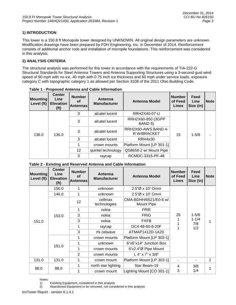
1) INTRODUCTION
This tower is a 150.8 ft Monopole tower designed by UNKNOWN. All original design parameters are unknown.Modification drawings have been prepared by FDH Engineering, Inc. in December of 2014. Reinforcementconsists of additional anchor rods and installation of micropile foundations. This reinforcement was consideredin this analysis.
2) ANALYSIS CRITERIA
The structural analysis was performed for this tower in accordance with the requirements of TIA-222-GStructural Standards for Steel Antenna Towers and Antenna Supporting Structures using a 3-second gust windspeed of 90 mph with no ice, 40 mph with 0.75 inch ice thickness and 60 mph under service loads, exposurecategory C with topographic category 1 as allowed per Section 3108 of the 2011 Ohio Building Code.
Table 1 - Proposed Antenna and Cable Information
MountingLevel (ft)
CenterLine
Elevation(ft)
Numberof
Antennas
AntennaManufacturer
Antenna ModelNumberof FeedLines
FeedLine
Size (in)Note
136.0 136.0
3 alcatel lucent RRH2X40-07-U
15 1-5/8 -
3 alcatel lucentRRH2X60-850 (3GPP
BAND 5)
3 alcatel lucentRRH2X60-AWS BAND 4-
R W/BRACKET
3 alcatel lucent RRH4x30
1 crown mounts Platform Mount [LP 301-1]
12 quintel technology QS8658-2 w/ Mount Pipe
3 raycap RCMDC-3315-PF-48
Table 2 - Existing and Reserved Antenna and Cable Information
MountingLevel (ft)
CenterLine
Elevation(ft)
Numberof
Antennas
AntennaManufacturer
Antenna ModelNumberof FeedLines
FeedLine
Size (in)Note
151.0
156.0 1 unknown 2.5”Ø x 10’ Omni
26111
1-5/81-1/47/81/2
1
146.0 1 unknown 2.5”Ø x 10’ Omni
153.0
12cellmax
technologiesCMA-BDHH/6521/E0-6 w/
Mount Pipe
1 nokia FRIE
3 nokia FRIG
3 nokia FXFB
1 raycap DC4-48-60-8-20F
3 rfs celwave ATMAP1412D-1A20
151.0
1 crown mounts Platform Mount [LP 303-1]
1 unknown 6”x6”x14” Junction Box
1 crown mounts 6’x2.4”Ø Pipe Mount
2 crown mounts L 4” x 7” x 3/8”
131.0 131.0 1 crown mount Platform Mount [LP 303-1] - - 2
88.0 88.01 north star lighting Star Beam-19 4
33/81/4
11 crown mount Lighting Mount [CO 301-1]
Notes:1) Exisiting Equipment, considered in this analysis2) Abandoned Equipment to be removed, not considered in this analysis

December 31, 2014150.8 Ft Monopole Tower Structural Analysis CCI BU No 826150Project Number 146HQV1400, Application 263384, Revision 1 Page 4
tnxTower Report - version 6.1.4.1
Table 3 - Design Antenna and Cable Information
MountingLevel (ft)
CenterLine
Elevation(ft)
Numberof
Antennas
AntennaManufacturer
Antenna ModelNumberof FeedLines
FeedLine
Size (in)
UNKNOWN
3) ANALYSIS PROCEDURE
Table 4 - Documents Provided
Document Remarks Reference Source
4-GEOTECHNICAL REPORTS Tower Engineering Professionals 3486717 CCISITES
4-TOWER FOUNDATIONDRAWINGS/DESIGN/SPECS
Tower Engineering Professionals 3486716 CCISITES
4-TOWER MANUFACTURERDRAWINGS
Tower Engineering Professionals 3773012 CCISITES
4-TOWER STRUCTURALANALYSIS REPORTS
Tower Engineering Professionals 3486718 CCISITES
4-TOWER REINFORCEMENTDESIGN/DATA/DRAWINGS
FDH Engineering, Inc.Project No.
146HQV1400APPENDIX D
3.1) Analysis Method
tnxTower (version 6.1.4.1), a commercially available analysis software package, was used to create athree-dimensional model of the tower and calculate member stresses for various loading cases.Selected output from the analysis is included in Appendix A.
3.2) Assumptions
1) Tower and structures were built in accordance with the manufacturer’s specifications.2) The tower and structures have been maintained in accordance with the manufacturer’s
specification.3) The configuration of antennas, transmission cables, mounts and other appurtenances are as
specified in Tables 1 and 2 and the referenced drawings.4) The existing equipment at elevation 131’ will be removed prior to increase in loading.5) The following material grades were assumed:
a) Pole: ASTM A572 Gr. 65b) Anchor Bolts: ASTM A615-J Gr. 75c) Base Plate: ASTM A572-60d) 0.33%, 60 ksi reinforcement bars in foundation with 3ksi concrete strength
6) The following dimensions were assumed:a) 50.62” Ø B.C for anchor bolts.b) 3” clear cover for foundational steel
7) The reinforcement listed in FDH Engineering, Inc. (Project No. 146HQV1400) ModificationDrawings for a 105.8’ Monopole dated December 31, 2014 must be installed a specified.
This analysis may be affected if any assumptions are not valid or have been made in error. FDHEngineering, Inc. should be notified to determine the effect on the structural integrity of the tower.

December 31, 2014150.8 Ft Monopole Tower Structural Analysis CCI BU No 826150Project Number 146HQV1400, Application 263384, Revision 1 Page 5
tnxTower Report - version 6.1.4.1
4) ANALYSIS RESULTS
Table 5 - Section Capacity (Summary)
SectionNo.
Elevation (ft)Component
TypeSize
CriticalElement
P (K)SF*P_allow
(K)%
CapacityPass / Fail
L1 150.8 - 124.3 Pole TP21.27x14.18x0.188 1 -6.58 884.71 84.6 Pass
L2124.3 -82.551
Pole TP29.77x20.1954x0.313 2 -14.40 2116.1691.4 Pass
L382.551 -40.724
Pole TP37.57x28.3577x0.375 3 -25.05 3206.6791.6 Pass
L4 40.724 - 0 Pole TP43.24x35.8874x0.438 4 -39.96 4420.84 88.9 Pass
Summary
Pole (L4) 91.6 Pass
Rating = 91.6 Pass
Table 6 - Tower Component Stresses vs. Capacity – LC4.5
Notes Component Elevation (ft) % Capacity Pass / Fail
1 Anchor Rods 0 76.4 Pass
1 Base Plate 0 73.5 Pass
1 Base Foundation 0 78.2 Pass
Structure Rating (max from all components) = 91.6%
Notes:1) See additional documentation in “Appendix C – Additional Calculations” for calculations supporting the % capacity
consumed.
4.1) Recommendations
The reinforcement listed in FDH Engineering, Inc. (Project No. 146HQV1400) Modification Drawings fora 105.8’ Monopole dated December 31, 2014 must be installed a specified.

December 31, 2014150.8 Ft Monopole Tower Structural Analysis CCI BU No 826150Project Number 146HQV1400, Application 263384, Revision 1 Page 6
tnxTower Report - version 6.1.4.1
APPENDIX A
TNXTOWER OUTPUT

Tower Analyst
FDH Engineering, Inc6521 Merdien Dr
Raleigh, NC 27616Phone: (919) 755-1012FAX: (919) 755-1031
Job:826150, N. Riverside Dublin
Project: 146HQV1400Client: Crown Castle. Drawn by: Byron K Webb App'd:
Code: TIA-222-G Date: 12/31/14 Scale: NTSPath:
\\FDH-SERVER\Projects\2014 Effective - Client Jobs\CROWNC_Crown Castle USA Inc\OH\826150 - N. Riverside Dublin HS\146HQV1400\Analysis\Passing Tower\826150, N. Riverside Dublin.eri
Dwg No. E-1
150.8 ft
124.3 ft
82.6 ft
40.7 ft
0.0 ft
REACTIONS - 90 mph WINDTORQUE 3 kip-ft
29 KSHEAR
3517 kip-ftMOMENT
40 K
AXIAL
40 mph WIND - 0.7500 in ICETORQUE 1 kip-ft
6 KSHEAR
771 kip-ftMOMENT
66 KAXIAL
ARE FACTOREDALL REACTIONS
Se
ctio
n1
23
4
Le
ng
th(f
t)2
6.5
04
4.3
64
5.4
74
5.3
3
Nu
mb
er
ofS
ide
s1
81
81
81
8
Th
ickn
ess
(in
)0
.18
80
0.3
13
00
.37
50
0.4
38
0
So
cke
tL
en
gth
(ft)
2.6
13
.64
4.6
0
To
pD
ia(i
n)
14
.18
00
20
.19
54
28
.35
77
35
.88
74
Bo
tD
ia(i
n)
21
.27
00
29
.77
00
37
.57
00
43
.24
00
Gra
de
A5
72
-65
We
igh
t(K
)0
.93
.76
.08
.41
9.0
Platform Mount [LP 601-1] 151(4) CMA-BDHH/6521/E0-6 w/ MountPipe
151(4) CMA-BDHH/6521/E0-6 w/ MountPipe
151(4) CMA-BDHH/6521/E0-6 w/ MountPipe
151FRIG 151FRIG 151FRIG 151FXFB 151FXFB 151FXFB 151FRIE 151ATMAP1412D-1A20 151ATMAP1412D-1A20 151ATMAP1412D-1A20 151DC4-48-60-8-20F 151(2) 5' Standoff 1516'x2.4" Pipe Mount 1516"x6"x14" Junction Box 15110'x2.4" Omni 15110'x2.4" Omni 151Lightning Rod 150.8Platform Mount [LP 301-1] 136(4) QS8658-2 w/ Mount Pipe 136(4) QS8658-2 w/ Mount Pipe 136(4) QS8658-2 w/ Mount Pipe 136RRH2X40-07-U 136RRH2X40-07-U 136RRH2X40-07-U 136RRH2X60-850 (3GPP BAND 5) 136RRH2X60-850 (3GPP BAND 5) 136RRH2X60-850 (3GPP BAND 5) 136(2) RCMDC-3315-PF-48 136RCMDC-3315-PF-48 136(3) RRH4x30 136(3) RRH2X60-AWS BAND 4-RW/BRACKET
136Star Beam-19 88DESIGNED APPURTENANCE LOADING
TYPE TYPEELEVATION ELEVATIONPlatform Mount [LP 601-1] 151
(4) CMA-BDHH/6521/E0-6 w/ MountPipe
151
(4) CMA-BDHH/6521/E0-6 w/ MountPipe
151
(4) CMA-BDHH/6521/E0-6 w/ MountPipe
151
FRIG 151
FRIG 151
FRIG 151
FXFB 151
FXFB 151
FXFB 151
FRIE 151
ATMAP1412D-1A20 151
ATMAP1412D-1A20 151
ATMAP1412D-1A20 151
DC4-48-60-8-20F 151
(2) 5' Standoff 151
6'x2.4" Pipe Mount 151
6"x6"x14" Junction Box 151
10'x2.4" Omni 151
10'x2.4" Omni 151
Lightning Rod 150.8
Platform Mount [LP 301-1] 136
(4) QS8658-2 w/ Mount Pipe 136
(4) QS8658-2 w/ Mount Pipe 136
(4) QS8658-2 w/ Mount Pipe 136
RRH2X40-07-U 136
RRH2X40-07-U 136
RRH2X40-07-U 136
RRH2X60-850 (3GPP BAND 5) 136
RRH2X60-850 (3GPP BAND 5) 136
RRH2X60-850 (3GPP BAND 5) 136
(2) RCMDC-3315-PF-48 136
RCMDC-3315-PF-48 136
(3) RRH4x30 136
(3) RRH2X60-AWS BAND 4-RW/BRACKET
136
Star Beam-19 88
MATERIAL STRENGTHGRADE GRADEFy FyFu Fu
A572-65 65 ksi 80 ksi
TOWER DESIGN NOTES1. Tower is located in Franklin County, Ohio.2. Tower designed for Exposure C to the TIA-222-G Standard.3. Tower designed for a 90 mph basic wind in accordance with the TIA-222-G Standard.4. Tower is also designed for a 40 mph basic wind with 0.75 in ice. Ice is considered to
increase in thickness with height.5. Deflections are based upon a 60 mph wind.6. Tower Structure Class II.7. Topographic Category 1 with Crest Height of 0.00 ft8. TOWER RATING: 94.9%

ttnnxxTToowweerrJob
826150, N. Riverside Dublin
Page
1 of 18
FDH Engineering, Inc6521 Merdien Dr
Project
146HQV1400
Date
15:38:12 12/31/14
Raleigh, NC 27616Phone: (919) 755-1012FAX: (919) 755-1031
Client
Crown Castle.Designed by
Byron K Webb
Tower Input Data
There is a pole section.This tower is designed using the TIA-222-G standard.The following design criteria apply:
Tower is located in Franklin County, Ohio.Basic wind speed of 90 mph.Structure Class II.Exposure Category C.Topographic Category 1.Crest Height 0.00 ft.Nominal ice thickness of 0.7500 in.Ice thickness is considered to increase with height.Ice density of 56 pcf.A wind speed of 40 mph is used in combination with ice.Temperature drop of 50 °F.Deflections calculated using a wind speed of 60 mph.A non-linear (P-delta) analysis was used.Pressures are calculated at each section.Stress ratio used in pole design is 1.Local bending stresses due to climbing loads, feed line supports, and appurtenance mounts are not considered.
Options
Consider Moments - Legs Distribute Leg Loads As Uniform Treat Feedline Bundles As CylinderConsider Moments - Horizontals Assume Legs Pinned Use ASCE 10 X-Brace Ly RulesConsider Moments - Diagonals √ Assume Rigid Index Plate Calculate Redundant Bracing ForcesUse Moment Magnification √ Use Clear Spans For Wind Area Ignore Redundant Members in FEA
√ Use Code Stress Ratios Use Clear Spans For KL/r SR Leg Bolts Resist Compression√ Use Code Safety Factors - Guys Retension Guys To Initial Tension All Leg Panels Have Same Allowable
Escalate Ice √ Bypass Mast Stability Checks Offset Girt At FoundationAlways Use Max Kz √ Use Azimuth Dish Coefficients √ Consider Feedline Torque Use Special Wind Profile √ Project Wind Area of Appurt. Include Angle Block Shear CheckInclude Bolts In Member Capacity Autocalc Torque Arm Areas PolesLeg Bolts Are At Top Of Section SR Members Have Cut Ends √ Include Shear-Torsion Interaction Secondary Horizontal Braces Leg √ Sort Capacity Reports By Component Always Use Sub-Critical FlowUse Diamond Inner Bracing (4 Sided) Triangulate Diamond Inner Bracing Use Top Mounted SocketsAdd IBC .6D+W Combination Use TIA-222-G Tension Splice Capacity
Exemption
Tapered Pole Section Geometry
Section Elevation
ft
SectionLength
ft
SpliceLength
ft
Numberof
Sides
TopDiameter
in
BottomDiameter
in
WallThickness
in
BendRadius
in
Pole Grade
L1 150.80-124.30 26.50 2.61 18 14.1800 21.2700 0.1880 0.7520 A572-65(65 ksi)
L2 124.30-82.55 44.36 3.64 18 20.1954 29.7700 0.3130 1.2520 A572-65(65 ksi)

ttnnxxTToowweerrJob
826150, N. Riverside Dublin
Page
2 of 18
FDH Engineering, Inc6521 Merdien Dr
Project
146HQV1400
Date
15:38:12 12/31/14
Raleigh, NC 27616Phone: (919) 755-1012FAX: (919) 755-1031
Client
Crown Castle.Designed by
Byron K Webb
Section Elevation
ft
SectionLength
ft
SpliceLength
ft
Numberof
Sides
TopDiameter
in
BottomDiameter
in
WallThickness
in
BendRadius
in
Pole Grade
L3 82.55-40.72 45.47 4.60 18 28.3577 37.5700 0.3750 1.5000 A572-65(65 ksi)
L4 40.72-0.00 45.33 18 35.8874 43.2400 0.4380 1.7520 A572-65(65 ksi)
Tapered Pole Properties
Section Tip Dia.in
Areain2
Iin4
rin
Cin
I/Cin3
Jin4
It/Qin2
win
w/t
L1 14.3987 8.3492 206.5102 4.9672 7.2034 28.6683 413.2922 4.1754 2.1648 11.51521.5981 12.5799 706.3788 7.4841 10.8052 65.3742 1413.6870 6.2911 3.4126 18.152
L2 21.0792 19.7524 986.5006 7.0583 10.2593 96.1569 1974.2993 9.8781 3.0035 9.59630.2293 29.2644 3208.1470 10.4572 15.1232 212.1347 6420.5153 14.6350 4.6886 14.98
L3 29.5446 33.3064 3294.9181 9.9339 14.4057 228.7230 6594.1718 16.6564 4.3310 11.54938.1496 44.2713 7738.0108 13.2042 19.0856 405.4380 15486.2034 22.1399 5.9523 15.873
L4 37.1992 49.2822 7824.3104 12.5845 18.2308 429.1806 15658.9161 24.6458 5.5453 12.66143.9070 59.5039 13772.4331 15.1947 21.9659 626.9910 27562.9883 29.7576 6.8394 15.615
TowerElevation
ft
GussetArea
(per face)
ft2
GussetThickness
in
Gusset Grade Adjust. FactorAf
Adjust.Factor
Ar
Weight Mult. Double AngleStitch BoltSpacing
Diagonalsin
Double AngleStitch BoltSpacing
Horizontalsin
L1150.80-124.30
1 1 1
L2124.30-82.55
1 1 1
L3 82.55-40.72 1 1 1L4 40.72-0.00 1 1 1
Feed Line/Linear Appurtenances - Entered As Round Or Flat
Description Sector ComponentType
Placement
ft
TotalNumber
NumberPer Row
Start/EndPosition
Width orDiameter
in
Perimeter
in
Weight
klfSafety Line 3/8 C Surface Ar
(CaAa)150.80 - 0.00 1 1 0.000
0.0000.3750 0.00
Feed Line/Linear Appurtenances - Entered As Area
Description Faceor
Leg
AllowShield
ComponentType
Placement
ft
TotalNumber
CAAA
ft2/ft
Weight
klf***
LDF4-50A(1/2'') C No Inside Pole 150.80 - 0.00 1 No Ice1/2'' Ice1'' Ice
0.000.000.00
0.000.000.00
LDF5-50A(7/8'') C No Inside Pole 150.80 - 0.00 1 No Ice1/2'' Ice
0.000.00
0.000.00

ttnnxxTToowweerrJob
826150, N. Riverside Dublin
Page
3 of 18
FDH Engineering, Inc6521 Merdien Dr
Project
146HQV1400
Date
15:38:12 12/31/14
Raleigh, NC 27616Phone: (919) 755-1012FAX: (919) 755-1031
Client
Crown Castle.Designed by
Byron K Webb
Description Faceor
Leg
AllowShield
ComponentType
Placement
ft
TotalNumber
CAAA
ft2/ft
Weight
klf1'' Ice 0.00 0.00
LDF6-50A(1-1/4'') C No Inside Pole 150.80 - 0.00 1 No Ice1/2'' Ice1'' Ice
0.000.000.00
0.000.000.00
LDF7-50A(1-5/8'') C No Inside Pole 150.80 - 0.00 26 No Ice1/2'' Ice1'' Ice
0.000.000.00
0.000.000.00
***LDF7-50A(1-5/8'') C No Inside Pole 136.00 - 0.00 12 No Ice
1/2'' Ice1'' Ice
0.000.000.00
0.000.000.00
HB158-1-08U8-S8J18(1-5/8)
C No Inside Pole 136.00 - 0.00 3 No Ice1/2'' Ice1'' Ice
0.000.000.00
0.000.000.00
***LDF1-50A(1/4'') C No Inside Pole 88.00 - 0.00 3 No Ice
1/2'' Ice1'' Ice
0.000.000.00
0.000.000.00
LDF2-50(3/8'') C No Inside Pole 88.00 - 0.00 4 No Ice1/2'' Ice1'' Ice
0.000.000.00
0.000.000.00
Feed Line/Linear Appurtenances Section Areas
TowerSection
TowerElevation
ft
Face AR
ft2
AF
ft2
CAAA
In Faceft2
CAAA
Out Faceft2
Weight
KL1 150.80-124.30 A
BC
0.0000.0000.000
0.0000.0000.000
0.0000.0000.994
0.0000.0000.000
0.000.000.76
L2 124.30-82.55 ABC
0.0000.0000.000
0.0000.0000.000
0.0000.0001.566
0.0000.0000.000
0.000.001.52
L3 82.55-40.72 ABC
0.0000.0000.000
0.0000.0000.000
0.0000.0001.569
0.0000.0000.000
0.000.001.54
L4 40.72-0.00 ABC
0.0000.0000.000
0.0000.0000.000
0.0000.0001.527
0.0000.0000.000
0.000.001.50
Feed Line/Linear Appurtenances Section Areas - With Ice
TowerSection
TowerElevation
ft
Faceor
Leg
IceThickness
in
AR
ft2
AF
ft2
CAAA
In Faceft2
CAAA
Out Faceft2
Weight
KL1 150.80-124.30 A
BC
1.729 0.0000.0000.000
0.0000.0000.000
0.0000.000
10.158
0.0000.0000.000
0.000.000.88
L2 124.30-82.55 ABC
1.680 0.0000.0000.000
0.0000.0000.000
0.0000.000
16.003
0.0000.0000.000
0.000.001.71
L3 82.55-40.72 ABC
1.595 0.0000.0000.000
0.0000.0000.000
0.0000.000
15.621
0.0000.0000.000
0.000.001.72
L4 40.72-0.00 A 1.431 0.000 0.000 0.000 0.000 0.00

ttnnxxTToowweerrJob
826150, N. Riverside Dublin
Page
4 of 18
FDH Engineering, Inc6521 Merdien Dr
Project
146HQV1400
Date
15:38:12 12/31/14
Raleigh, NC 27616Phone: (919) 755-1012FAX: (919) 755-1031
Client
Crown Castle.Designed by
Byron K Webb
TowerSection
TowerElevation
ft
Faceor
Leg
IceThickness
in
AR
ft2
AF
ft2
CAAA
In Faceft2
CAAA
Out Faceft2
Weight
KBC
0.0000.000
0.0000.000
0.00014.521
0.0000.000
0.001.66
Feed Line Center of Pressure
Section Elevation
ft
CPX
in
CPZ
in
CPX
Icein
CPZ
Icein
L1 150.80-124.30 0.0000 0.0552 0.0000 0.3994L2 124.30-82.55 0.0000 0.0552 0.0000 0.4373L3 82.55-40.72 0.0000 0.0553 0.0000 0.4530L4 40.72-0.00 0.0000 0.0553 0.0000 0.4490
Shielding Factor Ka
TowerSection
Feed LineRecord No.
Description Feed LineSegment Elev.
Ka
No IceKa
IceL1 1 Safety Line 3/8 124.30 -
150.801.0000 1.0000
L2 1 Safety Line 3/8 82.55 - 124.30 1.0000 1.0000L3 1 Safety Line 3/8 40.72 - 82.55 1.0000 1.0000
Discrete Tower Loads
Description Faceor
Leg
OffsetType
Offsets:Horz
LateralVert
ftftft
AzimuthAdjustment
°
Placement
ft
CAAA
Front
ft2
CAAA
Side
ft2
Weight
K
Lightning Rod C From Leg 0.000.002.00
0.0000 150.80 No Ice1/2'' Ice1'' Ice
0.250.660.97
0.250.660.97
0.030.030.04
***Platform Mount [LP 601-1] C None 0.0000 151.00 No Ice
1/2'' Ice1'' Ice
28.4733.5938.71
28.4733.5938.71
1.121.511.91
(4) CMA-BDHH/6521/E0-6w/ Mount Pipe
A From Leg 3.100.002.00
0.0000 151.00 No Ice1/2'' Ice1'' Ice
12.0512.7813.49
6.778.079.18
0.090.170.26
(4) CMA-BDHH/6521/E0-6w/ Mount Pipe
B From Leg 3.100.002.00
0.0000 151.00 No Ice1/2'' Ice1'' Ice
12.0512.7813.49
6.778.079.18
0.090.170.26

ttnnxxTToowweerrJob
826150, N. Riverside Dublin
Page
5 of 18
FDH Engineering, Inc6521 Merdien Dr
Project
146HQV1400
Date
15:38:12 12/31/14
Raleigh, NC 27616Phone: (919) 755-1012FAX: (919) 755-1031
Client
Crown Castle.Designed by
Byron K Webb
Description Faceor
Leg
OffsetType
Offsets:Horz
LateralVert
ftftft
AzimuthAdjustment
°
Placement
ft
CAAA
Front
ft2
CAAA
Side
ft2
Weight
K
(4) CMA-BDHH/6521/E0-6w/ Mount Pipe
C From Leg 3.100.002.00
0.0000 151.00 No Ice1/2'' Ice1'' Ice
12.0512.7813.49
6.778.079.18
0.090.170.26
FRIG A From Leg 3.100.002.00
0.0000 151.00 No Ice1/2'' Ice1'' Ice
2.793.023.25
1.101.271.44
0.060.070.09
FRIG B From Leg 3.100.002.00
0.0000 151.00 No Ice1/2'' Ice1'' Ice
2.793.023.25
1.101.271.44
0.060.070.09
FRIG C From Leg 3.100.002.00
0.0000 151.00 No Ice1/2'' Ice1'' Ice
2.793.023.25
1.101.271.44
0.060.070.09
FXFB A From Leg 3.100.002.00
0.0000 151.00 No Ice1/2'' Ice1'' Ice
3.854.114.39
1.071.251.44
0.060.080.10
FXFB B From Leg 3.100.002.00
0.0000 151.00 No Ice1/2'' Ice1'' Ice
3.854.114.39
1.071.251.44
0.060.080.10
FXFB C From Leg 3.100.002.00
0.0000 151.00 No Ice1/2'' Ice1'' Ice
3.854.114.39
1.071.251.44
0.060.080.10
FRIE A From Leg 3.100.002.00
0.0000 151.00 No Ice1/2'' Ice1'' Ice
3.854.114.39
1.071.251.44
0.060.080.10
ATMAP1412D-1A20 A From Leg 3.100.002.00
0.0000 151.00 No Ice1/2'' Ice1'' Ice
0.470.570.69
1.171.311.47
0.010.020.03
ATMAP1412D-1A20 B From Leg 3.100.002.00
0.0000 151.00 No Ice1/2'' Ice1'' Ice
0.470.570.69
1.171.311.47
0.010.020.03
ATMAP1412D-1A20 C From Leg 3.100.002.00
0.0000 151.00 No Ice1/2'' Ice1'' Ice
0.470.570.69
1.171.311.47
0.010.020.03
DC4-48-60-8-20F C From Leg 3.100.002.00
0.0000 151.00 No Ice1/2'' Ice1'' Ice
1.741.922.11
0.820.951.09
0.010.030.04
(2) 5' Standoff C From Leg 3.100.000.00
0.0000 151.00 No Ice1/2'' Ice1'' Ice
2.332.753.18
0.160.210.28
0.090.110.13
6'x2.4'' Pipe Mount C From Leg 5.600.000.00
0.0000 151.00 No Ice1/2'' Ice1'' Ice
1.441.932.30
1.441.932.30
0.030.040.06
6''x6''x14'' Junction Box C From Leg 5.600.000.00
0.0000 151.00 No Ice1/2'' Ice1'' Ice
0.820.951.09
0.820.951.09
0.020.030.04
10'x2.4'' Omni C From Leg 5.600.005.00
0.0000 151.00 No Ice1/2'' Ice1'' Ice
2.403.434.47
2.403.434.47
0.020.040.06
10'x2.4'' Omni C From Leg 5.600.00-5.00
0.0000 151.00 No Ice1/2'' Ice1'' Ice
2.403.434.47
2.403.434.47
0.020.040.06
***Platform Mount [LP 301-1] C None 0.0000 136.00 No Ice
1/2'' Ice1'' Ice
30.1040.8051.50
30.1040.8051.50
1.592.032.47
(4) QS8658-2 w/ Mount Pipe A From Leg 4.000.00
0.0000 136.00 No Ice1/2'' Ice
11.8112.53
11.1612.67
0.150.24

ttnnxxTToowweerrJob
826150, N. Riverside Dublin
Page
6 of 18
FDH Engineering, Inc6521 Merdien Dr
Project
146HQV1400
Date
15:38:12 12/31/14
Raleigh, NC 27616Phone: (919) 755-1012FAX: (919) 755-1031
Client
Crown Castle.Designed by
Byron K Webb
Description Faceor
Leg
OffsetType
Offsets:Horz
LateralVert
ftftft
AzimuthAdjustment
°
Placement
ft
CAAA
Front
ft2
CAAA
Side
ft2
Weight
K
0.00 1'' Ice 13.25 14.19 0.35(4) QS8658-2 w/ Mount Pipe B From Leg 4.00
0.000.00
0.0000 136.00 No Ice1/2'' Ice1'' Ice
11.8112.5313.25
11.1612.6714.19
0.150.240.35
(4) QS8658-2 w/ Mount Pipe C From Leg 4.000.000.00
0.0000 136.00 No Ice1/2'' Ice1'' Ice
11.8112.5313.25
11.1612.6714.19
0.150.240.35
RRH2X40-07-U A From Leg 4.000.000.00
0.0000 136.00 No Ice1/2'' Ice1'' Ice
2.252.452.66
1.231.391.55
0.050.070.09
RRH2X40-07-U B From Leg 4.000.000.00
0.0000 136.00 No Ice1/2'' Ice1'' Ice
2.252.452.66
1.231.391.55
0.050.070.09
RRH2X40-07-U C From Leg 4.000.000.00
0.0000 136.00 No Ice1/2'' Ice1'' Ice
2.252.452.66
1.231.391.55
0.050.070.09
RRH2X60-850 (3GPP BAND5)
A From Leg 4.000.000.00
0.0000 136.00 No Ice1/2'' Ice1'' Ice
2.122.322.53
1.661.852.04
0.050.070.09
RRH2X60-850 (3GPP BAND5)
B From Leg 4.000.000.00
0.0000 136.00 No Ice1/2'' Ice1'' Ice
2.122.322.53
1.661.852.04
0.050.070.09
RRH2X60-850 (3GPP BAND5)
C From Leg 4.000.000.00
0.0000 136.00 No Ice1/2'' Ice1'' Ice
2.122.322.53
1.661.852.04
0.050.070.09
(2) RCMDC-3315-PF-48 A From Leg 4.000.000.00
0.0000 136.00 No Ice1/2'' Ice1'' Ice
4.334.614.90
2.562.793.04
0.020.050.09
RCMDC-3315-PF-48 B From Leg 4.000.000.00
0.0000 136.00 No Ice1/2'' Ice1'' Ice
4.334.614.90
2.562.793.04
0.020.050.09
(3) RRH4x30 A From Leg 4.000.000.00
0.0000 136.00 No Ice1/2'' Ice1'' Ice
3.964.274.60
1.822.082.36
0.060.080.10
(3) RRH2X60-AWS BAND4-R W/BRACKET
A From Leg 4.000.000.00
0.0000 136.00 No Ice1/2'' Ice1'' Ice
3.784.094.41
2.052.322.61
0.060.080.11
***Star Beam-19 A From Leg 0.00
0.000.00
0.0000 88.00 No Ice1/2'' Ice1'' Ice
65.1478.1791.20
11.4113.7015.98
1.782.132.49
Compression Checks
Pole Design Data

ttnnxxTToowweerrJob
826150, N. Riverside Dublin
Page
7 of 18
FDH Engineering, Inc6521 Merdien Dr
Project
146HQV1400
Date
15:38:12 12/31/14
Raleigh, NC 27616Phone: (919) 755-1012FAX: (919) 755-1031
Client
Crown Castle.Designed by
Byron K Webb
SectionNo.
Elevation
ft
Size L
ft
Lu
ft
Kl/r A
in2
Pu
K
Pn
K
RatioPu
Pn
L1 150.8 -149.543
TP21.27x14.18x0.188 26.50 0.00 0.0 8.5499 -1.63 635.22 0.003
149.543 -148.285
8.7507 -1.71 650.13 0.003
148.285 -147.028
8.9514 -1.80 665.04 0.003
147.028 -145.771
9.1521 -1.88 679.96 0.003
145.771 -144.513
9.3528 -1.97 694.87 0.003
144.513 -143.256
9.5536 -2.07 709.78 0.003
143.256 -141.999
9.7543 -2.16 724.70 0.003
141.999 -140.741
9.9550 -2.26 739.61 0.003
140.741 -139.484
10.1558 -2.36 754.52 0.003
139.484 -138.227
10.3565 -2.46 769.43 0.003
138.227 -136.97
10.5572 -2.51 784.35 0.003
136.97 -135.712
10.7579 -5.65 799.26 0.007
135.712 -134.455
10.9587 -5.77 814.17 0.007
134.455 -133.198
11.1594 -5.90 829.09 0.007
133.198 -131.94
11.3601 -6.04 841.45 0.007
131.94 -130.683
11.5609 -6.18 852.47 0.007
130.683 -129.426
11.7616 -6.32 863.35 0.007
129.426 -128.168
11.9623 -6.42 874.10 0.007
128.168 -126.911
12.1630 -6.57 884.71 0.007
126.911 -124.3
12.5799 -2.70 906.32 0.003
L2 126.911 -124.3
TP29.77x20.1954x0.313 44.36 0.00 0.0 20.3123 -4.32 1509.10 0.003
124.3 -122.183
20.7663 -7.33 1542.83 0.005
122.183 -120.066
21.2202 -7.65 1576.55 0.005
120.066 -117.949
21.6741 -7.98 1610.28 0.005
117.949 -115.832
22.1281 -8.31 1644.01 0.005
115.832 -113.715
22.5820 -8.66 1677.73 0.005
113.715 -111.598
23.0360 -9.00 1711.46 0.005
111.598 -109.481
23.4899 -9.36 1745.18 0.005
109.481 -107.364
23.9438 -9.72 1778.91 0.005
107.364 -105.247
24.3978 -10.08 1812.63 0.006

ttnnxxTToowweerrJob
826150, N. Riverside Dublin
Page
8 of 18
FDH Engineering, Inc6521 Merdien Dr
Project
146HQV1400
Date
15:38:12 12/31/14
Raleigh, NC 27616Phone: (919) 755-1012FAX: (919) 755-1031
Client
Crown Castle.Designed by
Byron K Webb
SectionNo.
Elevation
ft
Size L
ft
Lu
ft
Kl/r A
in2
Pu
K
Pn
K
RatioPu
Pn
105.247 -103.13
24.8517 -10.45 1846.36 0.006
103.13 -101.013
25.3057 -10.82 1880.08 0.006
101.013 -98.896
25.7596 -11.20 1913.81 0.006
98.896 -96.779
26.2135 -11.59 1947.54 0.006
96.779 -94.662
26.6675 -11.98 1981.26 0.006
94.662 -92.545
27.1214 -12.37 2014.99 0.006
92.545 -90.428
27.5754 -12.77 2048.71 0.006
90.428 -88.311
28.0293 -13.17 2082.44 0.006
88.311 -86.194
28.4833 -15.34 2116.16 0.007
86.194 -82.551
29.2644 -7.64 2174.20 0.004
L3 86.194 -82.551
TP37.57x28.3577x0.375 45.47 0.00 0.0 34.1849 -8.85 2539.77 0.003
82.551 -80.483
34.6836 -16.94 2576.82 0.007
80.483 -78.415
35.1823 -17.40 2613.87 0.007
78.415 -76.347
35.6810 -17.87 2650.92 0.007
76.347 -74.279
36.1797 -18.34 2687.97 0.007
74.279 -72.211
36.6784 -18.81 2725.02 0.007
72.211 -70.143
37.1771 -19.29 2762.07 0.007
70.143 -68.075
37.6757 -19.77 2799.12 0.007
68.075 -66.007
38.1744 -20.26 2836.17 0.007
66.007 -63.939
38.6731 -20.75 2873.22 0.007
63.939 -61.871
39.1718 -21.25 2910.27 0.007
61.871 -59.803
39.6705 -21.75 2947.32 0.007
59.803 -57.735
40.1692 -22.25 2984.37 0.007
57.735 -55.667
40.6679 -22.76 3021.42 0.008
55.667 -53.599
41.1666 -23.28 3058.47 0.008
53.599 -51.531
41.6653 -23.80 3095.52 0.008
51.531 -49.463
42.1640 -24.32 3132.57 0.008
49.463 -47.395
42.6627 -24.85 3169.62 0.008
47.395 -45.327
43.1614 -25.38 3206.67 0.008
45.327 -40.724
44.2713 -12.86 3289.14 0.004

ttnnxxTToowweerrJob
826150, N. Riverside Dublin
Page
9 of 18
FDH Engineering, Inc6521 Merdien Dr
Project
146HQV1400
Date
15:38:12 12/31/14
Raleigh, NC 27616Phone: (919) 755-1012FAX: (919) 755-1031
Client
Crown Castle.Designed by
Byron K Webb
SectionNo.
Elevation
ft
Size L
ft
Lu
ft
Kl/r A
in2
Pu
K
Pn
K
RatioPu
Pn
L4 45.327 -40.724
TP43.24x35.8874x0.438 45.33 0.00 0.0 50.3202 -14.55 3738.54 0.004
40.724 -38.5806
50.8036 -28.02 3774.45 0.007
38.5806 -36.4373
51.2869 -28.64 3810.36 0.008
36.4373 -34.2939
51.7703 -29.26 3846.27 0.008
34.2939 -32.1505
52.2536 -29.89 3882.18 0.008
32.1505 -30.0072
52.7370 -30.52 3918.09 0.008
30.0072 -27.8638
53.2203 -31.15 3954.00 0.008
27.8638 -25.7204
53.7037 -31.79 3989.91 0.008
25.7204 -23.5771
54.1870 -32.44 4025.82 0.008
23.5771 -21.4337
54.6704 -33.09 4061.74 0.008
21.4337 -19.2903
55.1537 -33.74 4097.65 0.008
19.2903 -17.1469
55.6371 -34.40 4133.56 0.008
17.1469 -15.0036
56.1204 -35.06 4169.47 0.008
15.0036 -12.8602
56.6038 -35.73 4205.38 0.008
12.8602 -10.7168
57.0871 -36.40 4241.29 0.009
10.7168 -8.57347
57.5705 -37.07 4277.20 0.009
8.57347 -6.43011
58.0538 -37.75 4313.11 0.009
6.43011 -4.28674
58.5372 -38.44 4349.02 0.009
4.28674 -2.14337
59.0205 -39.13 4384.93 0.009
2.14337 - 0 59.5039 -39.82 4420.84 0.009
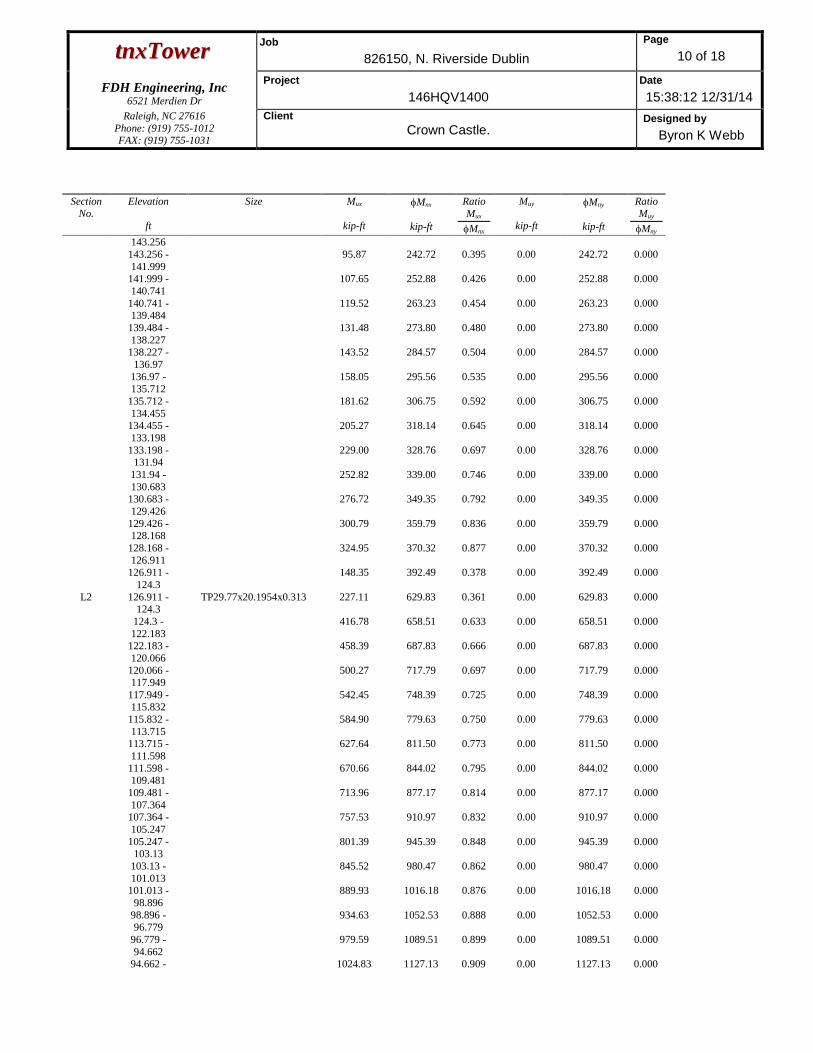
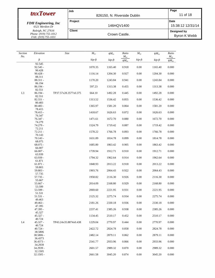
Pole Bending Design Data
SectionNo.
Elevation
ft
Size Mux
kip-ft
Mnx
kip-ft
RatioMux
Mnx
Muy
kip-ft
Mny
kip-ft
RatioMuy
Mny
L1 150.8 -149.543
TP21.27x14.18x0.188 26.96 186.19 0.145 0.00 186.19 0.000
149.543 -148.285
38.23 195.09 0.196 0.00 195.09 0.000
148.285 -147.028
49.59 204.20 0.243 0.00 204.20 0.000
147.028 -145.771
61.03 213.52 0.286 0.00 213.52 0.000
145.771 -144.513
72.56 223.05 0.325 0.00 223.05 0.000
144.513 - 84.17 232.78 0.362 0.00 232.78 0.000
ttnnxxTToowweerrJob
826150, N. Riverside Dublin
Page
10 of 18
FDH Engineering, Inc6521 Merdien Dr
Project
146HQV1400
Date
15:38:12 12/31/14
Raleigh, NC 27616Phone: (919) 755-1012FAX: (919) 755-1031
Client
Crown Castle.Designed by
Byron K Webb
SectionNo.
Elevation
ft
Size Mux
kip-ft
Mnx
kip-ft
RatioMux
Mnx
Muy
kip-ft
Mny
kip-ft
RatioMuy
Mny
143.256143.256 -141.999
95.87 242.72 0.395 0.00 242.72 0.000
141.999 -140.741
107.65 252.88 0.426 0.00 252.88 0.000
140.741 -139.484
119.52 263.23 0.454 0.00 263.23 0.000
139.484 -138.227
131.48 273.80 0.480 0.00 273.80 0.000
138.227 -136.97
143.52 284.57 0.504 0.00 284.57 0.000
136.97 -135.712
158.05 295.56 0.535 0.00 295.56 0.000
135.712 -134.455
181.62 306.75 0.592 0.00 306.75 0.000
134.455 -133.198
205.27 318.14 0.645 0.00 318.14 0.000
133.198 -131.94
229.00 328.76 0.697 0.00 328.76 0.000
131.94 -130.683
252.82 339.00 0.746 0.00 339.00 0.000
130.683 -129.426
276.72 349.35 0.792 0.00 349.35 0.000
129.426 -128.168
300.79 359.79 0.836 0.00 359.79 0.000
128.168 -126.911
324.95 370.32 0.877 0.00 370.32 0.000
126.911 -124.3
148.35 392.49 0.378 0.00 392.49 0.000
L2 126.911 -124.3
TP29.77x20.1954x0.313 227.11 629.83 0.361 0.00 629.83 0.000
124.3 -122.183
416.78 658.51 0.633 0.00 658.51 0.000
122.183 -120.066
458.39 687.83 0.666 0.00 687.83 0.000
120.066 -117.949
500.27 717.79 0.697 0.00 717.79 0.000
117.949 -115.832
542.45 748.39 0.725 0.00 748.39 0.000
115.832 -113.715
584.90 779.63 0.750 0.00 779.63 0.000
113.715 -111.598
627.64 811.50 0.773 0.00 811.50 0.000
111.598 -109.481
670.66 844.02 0.795 0.00 844.02 0.000
109.481 -107.364
713.96 877.17 0.814 0.00 877.17 0.000
107.364 -105.247
757.53 910.97 0.832 0.00 910.97 0.000
105.247 -103.13
801.39 945.39 0.848 0.00 945.39 0.000
103.13 -101.013
845.52 980.47 0.862 0.00 980.47 0.000
101.013 -98.896
889.93 1016.18 0.876 0.00 1016.18 0.000
98.896 -96.779
934.63 1052.53 0.888 0.00 1052.53 0.000
96.779 -94.662
979.59 1089.51 0.899 0.00 1089.51 0.000
94.662 - 1024.83 1127.13 0.909 0.00 1127.13 0.000
ttnnxxTToowweerrJob
826150, N. Riverside Dublin
Page
11 of 18
FDH Engineering, Inc6521 Merdien Dr
Project
146HQV1400
Date
15:38:12 12/31/14
Raleigh, NC 27616Phone: (919) 755-1012FAX: (919) 755-1031
Client
Crown Castle.Designed by
Byron K Webb
SectionNo.
Elevation
ft
Size Mux
kip-ft
Mnx
kip-ft
RatioMux
Mnx
Muy
kip-ft
Mny
kip-ft
RatioMuy
Mny
92.54592.545 -90.428
1070.35 1165.40 0.918 0.00 1165.40 0.000
90.428 -88.311
1116.14 1204.30 0.927 0.00 1204.30 0.000
88.311 -86.194
1170.20 1243.84 0.941 0.00 1243.84 0.000
86.194 -82.551
597.23 1313.38 0.455 0.00 1313.38 0.000
L3 86.194 -82.551
TP37.57x28.3577x0.375 664.10 1492.28 0.445 0.00 1492.28 0.000
82.551 -80.483
1313.52 1536.42 0.855 0.00 1536.42 0.000
80.483 -78.415
1365.97 1581.20 0.864 0.00 1581.20 0.000
78.415 -76.347
1418.67 1626.63 0.872 0.00 1626.63 0.000
76.347 -74.279
1471.61 1672.70 0.880 0.00 1672.70 0.000
74.279 -72.211
1524.79 1719.42 0.887 0.00 1719.42 0.000
72.211 -70.143
1578.22 1766.78 0.893 0.00 1766.78 0.000
70.143 -68.075
1631.89 1814.78 0.899 0.00 1814.78 0.000
68.075 -66.007
1685.80 1863.42 0.905 0.00 1863.42 0.000
66.007 -63.939
1739.94 1912.71 0.910 0.00 1912.71 0.000
63.939 -61.871
1794.32 1962.64 0.914 0.00 1962.64 0.000
61.871 -59.803
1848.93 2013.22 0.918 0.00 2013.22 0.000
59.803 -57.735
1903.76 2064.43 0.922 0.00 2064.43 0.000
57.735 -55.667
1958.82 2116.30 0.926 0.00 2116.30 0.000
55.667 -53.599
2014.09 2168.80 0.929 0.00 2168.80 0.000
53.599 -51.531
2069.60 2221.95 0.931 0.00 2221.95 0.000
51.531 -49.463
2125.32 2275.74 0.934 0.00 2275.74 0.000
49.463 -47.395
2181.26 2330.18 0.936 0.00 2330.18 0.000
47.395 -45.327
2237.41 2385.26 0.938 0.00 2385.26 0.000
45.327 -40.724
1134.45 2510.17 0.452 0.00 2510.17 0.000
L4 45.327 -40.724
TP43.24x35.8874x0.438 1229.04 2770.97 0.444 0.00 2770.97 0.000
40.724 -38.5806
2422.72 2824.78 0.858 0.00 2824.78 0.000
38.5806 -36.4373
2482.14 2879.11 0.862 0.00 2879.11 0.000
36.4373 -34.2939
2541.77 2933.96 0.866 0.00 2933.96 0.000
34.2939 -32.1505
2601.57 2989.32 0.870 0.00 2989.32 0.000
32.1505 - 2661.58 3045.20 0.874 0.00 3045.20 0.000

ttnnxxTToowweerrJob
826150, N. Riverside Dublin
Page
12 of 18
FDH Engineering, Inc6521 Merdien Dr
Project
146HQV1400
Date
15:38:12 12/31/14
Raleigh, NC 27616Phone: (919) 755-1012FAX: (919) 755-1031
Client
Crown Castle.Designed by
Byron K Webb
SectionNo.
Elevation
ft
Size Mux
kip-ft
Mnx
kip-ft
RatioMux
Mnx
Muy
kip-ft
Mny
kip-ft
RatioMuy
Mny
30.007230.0072 -27.8638
2721.76 3101.60 0.878 0.00 3101.60 0.000
27.8638 -25.7204
2782.11 3158.51 0.881 0.00 3158.51 0.000
25.7204 -23.5771
2842.62 3215.94 0.884 0.00 3215.94 0.000
23.5771 -21.4337
2903.29 3273.89 0.887 0.00 3273.89 0.000
21.4337 -19.2903
2964.11 3332.36 0.889 0.00 3332.36 0.000
19.2903 -17.1469
3025.07 3391.35 0.892 0.00 3391.35 0.000
17.1469 -15.0036
3086.17 3450.85 0.894 0.00 3450.85 0.000
15.0036 -12.8602
3147.39 3510.87 0.896 0.00 3510.87 0.000
12.8602 -10.7168
3208.74 3571.41 0.898 0.00 3571.41 0.000
10.7168 -8.57347
3270.20 3632.46 0.900 0.00 3632.46 0.000
8.57347 -6.43011
3331.77 3694.03 0.902 0.00 3694.03 0.000
6.43011 -4.28674
3393.43 3756.13 0.903 0.00 3756.13 0.000
4.28674 -2.14337
3455.19 3818.73 0.905 0.00 3818.73 0.000
2.14337 - 0 3517.04 3881.86 0.906 0.00 3881.86 0.000
Pole Shear Design Data
SectionNo.
Elevation
ft
Size ActualVu
K
Vn
K
RatioVu
Vn
ActualTu
kip-ft
Tn
kip-ft
RatioTu
Tn
L1 150.8 -149.543
TP21.27x14.18x0.188 8.94 317.61 0.028 0.26 372.83 0.001
149.543 -148.285
9.01 325.07 0.028 0.26 390.66 0.001
148.285 -147.028
9.07 332.52 0.027 0.26 408.90 0.001
147.028 -145.771
9.14 339.98 0.027 0.26 427.56 0.001
145.771 -144.513
9.21 347.44 0.026 0.26 446.64 0.001
144.513 -143.256
9.27 354.89 0.026 0.26 466.13 0.001
143.256 -141.999
9.34 362.35 0.026 0.26 486.04 0.001
141.999 -140.741
9.41 369.80 0.025 0.26 506.37 0.001
140.741 -139.484
9.48 377.26 0.025 0.26 527.11 0.000
139.484 -138.227
9.56 384.72 0.025 0.26 548.27 0.000
138.227 -136.97
9.64 392.17 0.025 1.45 569.84 0.003

ttnnxxTToowweerrJob
826150, N. Riverside Dublin
Page
13 of 18
FDH Engineering, Inc6521 Merdien Dr
Project
146HQV1400
Date
15:38:12 12/31/14
Raleigh, NC 27616Phone: (919) 755-1012FAX: (919) 755-1031
Client
Crown Castle.Designed by
Byron K Webb
SectionNo.
Elevation
ft
Size ActualVu
K
Vn
K
RatioVu
Vn
ActualTu
kip-ft
Tn
kip-ft
RatioTu
Tn
136.97 -135.712
18.72 399.63 0.047 2.37 591.84 0.004
135.712 -134.455
18.79 407.09 0.046 2.37 614.24 0.004
134.455 -133.198
18.86 414.54 0.045 2.36 637.07 0.004
133.198 -131.94
18.92 420.73 0.045 2.36 658.32 0.004
131.94 -130.683
18.99 426.23 0.045 2.36 678.83 0.003
130.683 -129.426
19.06 431.67 0.044 2.36 699.55 0.003
129.426 -128.168
19.19 437.05 0.044 1.85 720.46 0.003
128.168 -126.911
19.25 442.35 0.044 1.85 741.55 0.002
126.911 -124.3
7.73 453.16 0.017 0.73 785.94 0.001
L2 126.911 -124.3
TP29.77x20.1954x0.313 11.72 754.55 0.016 1.12 1261.19 0.001
124.3 -122.183
19.60 771.41 0.025 1.85 1318.63 0.001
122.183 -120.066
19.74 788.28 0.025 1.85 1377.34 0.001
120.066 -117.949
19.87 805.14 0.025 1.84 1437.33 0.001
117.949 -115.832
20.01 822.00 0.024 1.84 1498.61 0.001
115.832 -113.715
20.14 838.87 0.024 1.84 1561.16 0.001
113.715 -111.598
20.27 855.73 0.024 1.84 1624.99 0.001
111.598 -109.481
20.41 872.59 0.023 1.84 1690.10 0.001
109.481 -107.364
20.54 889.45 0.023 1.83 1756.49 0.001
107.364 -105.247
20.67 906.32 0.023 1.83 1824.16 0.001
105.247 -103.13
20.80 923.18 0.023 1.83 1893.10 0.001
103.13 -101.013
20.94 940.04 0.022 1.83 1963.33 0.001
101.013 -98.896
21.07 956.90 0.022 1.83 2034.83 0.001
98.896 -96.779
21.20 973.77 0.022 1.82 2107.62 0.001
96.779 -94.662
21.33 990.63 0.022 1.82 2181.68 0.001
94.662 -92.545
21.46 1007.49 0.021 1.82 2257.03 0.001
92.545 -90.428
21.59 1024.36 0.021 1.82 2333.64 0.001
90.428 -88.311
21.72 1041.22 0.021 1.82 2411.54 0.001
88.311 -86.194
24.88 1058.08 0.024 1.82 2490.72 0.001
86.194 -82.551
12.01 1087.10 0.011 0.86 2629.97 0.000
L3 86.194 -82.551
TP37.57x28.3577x0.375 13.20 1269.88 0.010 0.96 2988.20 0.000

ttnnxxTToowweerrJob
826150, N. Riverside Dublin
Page
14 of 18
FDH Engineering, Inc6521 Merdien Dr
Project
146HQV1400
Date
15:38:12 12/31/14
Raleigh, NC 27616Phone: (919) 755-1012FAX: (919) 755-1031
Client
Crown Castle.Designed by
Byron K Webb
SectionNo.
Elevation
ft
Size ActualVu
K
Vn
K
RatioVu
Vn
ActualTu
kip-ft
Tn
kip-ft
RatioTu
Tn
82.551 -80.483
25.33 1288.41 0.020 1.81 3076.59 0.001
80.483 -78.415
25.45 1306.93 0.019 1.81 3166.27 0.001
78.415 -76.347
25.57 1325.46 0.019 1.81 3257.23 0.001
76.347 -74.279
25.69 1343.98 0.019 1.81 3349.49 0.001
74.279 -72.211
25.81 1362.51 0.019 1.81 3443.03 0.001
72.211 -70.143
25.93 1381.03 0.019 1.81 3537.87 0.001
70.143 -68.075
26.05 1399.56 0.019 1.80 3633.99 0.000
68.075 -66.007
26.16 1418.09 0.018 1.80 3731.40 0.000
66.007 -63.939
26.27 1436.61 0.018 1.80 3830.10 0.000
63.939 -61.871
26.39 1455.14 0.018 1.80 3930.08 0.000
61.871 -59.803
26.50 1473.66 0.018 1.80 4031.36 0.000
59.803 -57.735
26.61 1492.19 0.018 1.80 4133.92 0.000
57.735 -55.667
26.72 1510.71 0.018 1.80 4237.77 0.000
55.667 -53.599
26.82 1529.24 0.018 1.80 4342.91 0.000
53.599 -51.531
26.93 1547.76 0.017 1.80 4449.34 0.000
51.531 -49.463
27.04 1566.29 0.017 1.80 4557.06 0.000
49.463 -47.395
27.14 1584.81 0.017 1.79 4666.06 0.000
47.395 -45.327
27.25 1603.34 0.017 1.79 4776.36 0.000
45.327 -40.724
13.35 1644.57 0.008 0.86 5026.48 0.000
L4 45.327 -40.724
TP43.24x35.8874x0.438 14.27 1869.27 0.008 0.93 5548.73 0.000
40.724 -38.5806
27.72 1887.23 0.015 1.79 5656.47 0.000
38.5806 -36.4373
27.82 1905.18 0.015 1.79 5765.27 0.000
36.4373 -34.2939
27.91 1923.14 0.015 1.79 5875.09 0.000
34.2939 -32.1505
28.00 1941.09 0.014 1.79 5985.95 0.000
32.1505 -30.0072
28.08 1959.05 0.014 1.79 6097.85 0.000
30.0072 -27.8638
28.16 1977.00 0.014 1.79 6210.78 0.000
27.8638 -25.7204
28.24 1994.96 0.014 1.79 6324.75 0.000
25.7204 -23.5771
28.32 2012.91 0.014 1.79 6439.76 0.000
23.5771 -21.4337
28.39 2030.87 0.014 1.79 6555.80 0.000
21.4337 -19.2903
28.46 2048.82 0.014 1.79 6672.87 0.000

ttnnxxTToowweerrJob
826150, N. Riverside Dublin
Page
15 of 18
FDH Engineering, Inc6521 Merdien Dr
Project
146HQV1400
Date
15:38:12 12/31/14
Raleigh, NC 27616Phone: (919) 755-1012FAX: (919) 755-1031
Client
Crown Castle.Designed by
Byron K Webb
SectionNo.
Elevation
ft
Size ActualVu
K
Vn
K
RatioVu
Vn
ActualTu
kip-ft
Tn
kip-ft
RatioTu
Tn
19.2903 -17.1469
28.52 2066.78 0.014 1.79 6790.99 0.000
17.1469 -15.0036
28.59 2084.73 0.014 1.79 6910.14 0.000
15.0036 -12.8602
28.64 2102.69 0.014 1.79 7030.32 0.000
12.8602 -10.7168
28.70 2120.64 0.014 1.79 7151.55 0.000
10.7168 -8.57347
28.75 2138.60 0.013 1.79 7273.81 0.000
8.57347 -6.43011
28.80 2156.55 0.013 1.79 7397.11 0.000
6.43011 -4.28674
28.85 2174.51 0.013 1.79 7521.43 0.000
4.28674 -2.14337
28.89 2192.46 0.013 1.79 7646.81 0.000
2.14337 - 0 28.93 2210.42 0.013 1.79 7773.21 0.000
Pole Interaction Design Data
SectionNo.
Elevation
ft
RatioPu
Pn
RatioMux
Mnx
RatioMuy
Mny
RatioVu
Vn
RatioTu
Tn
Comb.StressRatio
Allow.StressRatio
Criteria
L1 150.8 -149.543
0.003 0.145 0.000 0.028 0.001 0.148 1.0004.8.2
149.543 -148.285
0.003 0.196 0.000 0.028 0.001 0.199 1.0004.8.2
148.285 -147.028
0.003 0.243 0.000 0.027 0.001 0.246 1.0004.8.2
147.028 -145.771
0.003 0.286 0.000 0.027 0.001 0.289 1.0004.8.2
145.771 -144.513
0.003 0.325 0.000 0.026 0.001 0.329 1.0004.8.2
144.513 -143.256
0.003 0.362 0.000 0.026 0.001 0.365 1.0004.8.2
143.256 -141.999
0.003 0.395 0.000 0.026 0.001 0.399 1.0004.8.2
141.999 -140.741
0.003 0.426 0.000 0.025 0.001 0.429 1.0004.8.2
140.741 -139.484
0.003 0.454 0.000 0.025 0.000 0.458 1.0004.8.2
139.484 -138.227
0.003 0.480 0.000 0.025 0.000 0.484 1.0004.8.2
138.227 -136.97
0.003 0.504 0.000 0.025 0.003 0.508 1.0004.8.2
136.97 -135.712
0.007 0.535 0.000 0.047 0.004 0.544 1.0004.8.2
135.712 -134.455
0.007 0.592 0.000 0.046 0.004 0.602 1.0004.8.2
134.455 -133.198
0.007 0.645 0.000 0.045 0.004 0.655 1.0004.8.2

ttnnxxTToowweerrJob
826150, N. Riverside Dublin
Page
16 of 18
FDH Engineering, Inc6521 Merdien Dr
Project
146HQV1400
Date
15:38:12 12/31/14
Raleigh, NC 27616Phone: (919) 755-1012FAX: (919) 755-1031
Client
Crown Castle.Designed by
Byron K Webb
SectionNo.
Elevation
ft
RatioPu
Pn
RatioMux
Mnx
RatioMuy
Mny
RatioVu
Vn
RatioTu
Tn
Comb.StressRatio
Allow.StressRatio
Criteria
133.198 -131.94
0.007 0.697 0.000 0.045 0.004 0.706 1.0004.8.2
131.94 -130.683
0.007 0.746 0.000 0.045 0.003 0.755 1.0004.8.2
130.683 -129.426
0.007 0.792 0.000 0.044 0.003 0.802 1.0004.8.2
129.426 -128.168
0.007 0.836 0.000 0.044 0.003 0.846 1.0004.8.2
128.168 -126.911
0.007 0.877 0.000 0.044 0.002 0.887 1.0004.8.2
126.911 -124.3
0.003 0.378 0.000 0.017 0.001 0.381 1.0004.8.2
L2 126.911 -124.3
0.003 0.361 0.000 0.016 0.001 0.364 1.0004.8.2
124.3 -122.183
0.005 0.633 0.000 0.025 0.001 0.638 1.0004.8.2
122.183 -120.066
0.005 0.666 0.000 0.025 0.001 0.672 1.0004.8.2
120.066 -117.949
0.005 0.697 0.000 0.025 0.001 0.703 1.0004.8.2
117.949 -115.832
0.005 0.725 0.000 0.024 0.001 0.731 1.0004.8.2
115.832 -113.715
0.005 0.750 0.000 0.024 0.001 0.756 1.0004.8.2
113.715 -111.598
0.005 0.773 0.000 0.024 0.001 0.779 1.0004.8.2
111.598 -109.481
0.005 0.795 0.000 0.023 0.001 0.801 1.0004.8.2
109.481 -107.364
0.005 0.814 0.000 0.023 0.001 0.820 1.0004.8.2
107.364 -105.247
0.006 0.832 0.000 0.023 0.001 0.838 1.0004.8.2
105.247 -103.13
0.006 0.848 0.000 0.023 0.001 0.854 1.0004.8.2
103.13 -101.013
0.006 0.862 0.000 0.022 0.001 0.869 1.0004.8.2
101.013 -98.896
0.006 0.876 0.000 0.022 0.001 0.882 1.0004.8.2
98.896 -96.779
0.006 0.888 0.000 0.022 0.001 0.894 1.0004.8.2
96.779 -94.662
0.006 0.899 0.000 0.022 0.001 0.906 1.0004.8.2
94.662 -92.545
0.006 0.909 0.000 0.021 0.001 0.916 1.0004.8.2
92.545 -90.428
0.006 0.918 0.000 0.021 0.001 0.925 1.0004.8.2
90.428 -88.311
0.006 0.927 0.000 0.021 0.001 0.934 1.0004.8.2
88.311 -86.194
0.007 0.941 0.000 0.024 0.001 0.949 1.0004.8.2
86.194 -82.551
0.004 0.455 0.000 0.011 0.000 0.458 1.0004.8.2

ttnnxxTToowweerrJob
826150, N. Riverside Dublin
Page
17 of 18
FDH Engineering, Inc6521 Merdien Dr
Project
146HQV1400
Date
15:38:12 12/31/14
Raleigh, NC 27616Phone: (919) 755-1012FAX: (919) 755-1031
Client
Crown Castle.Designed by
Byron K Webb
SectionNo.
Elevation
ft
RatioPu
Pn
RatioMux
Mnx
RatioMuy
Mny
RatioVu
Vn
RatioTu
Tn
Comb.StressRatio
Allow.StressRatio
Criteria
L3 86.194 -82.551
0.003 0.445 0.000 0.010 0.000 0.449 1.0004.8.2
82.551 -80.483
0.007 0.855 0.000 0.020 0.001 0.862 1.0004.8.2
80.483 -78.415
0.007 0.864 0.000 0.019 0.001 0.871 1.0004.8.2
78.415 -76.347
0.007 0.872 0.000 0.019 0.001 0.879 1.0004.8.2
76.347 -74.279
0.007 0.880 0.000 0.019 0.001 0.887 1.0004.8.2
74.279 -72.211
0.007 0.887 0.000 0.019 0.001 0.894 1.0004.8.2
72.211 -70.143
0.007 0.893 0.000 0.019 0.001 0.901 1.0004.8.2
70.143 -68.075
0.007 0.899 0.000 0.019 0.000 0.907 1.0004.8.2
68.075 -66.007
0.007 0.905 0.000 0.018 0.000 0.912 1.0004.8.2
66.007 -63.939
0.007 0.910 0.000 0.018 0.000 0.917 1.0004.8.2
63.939 -61.871
0.007 0.914 0.000 0.018 0.000 0.922 1.0004.8.2
61.871 -59.803
0.007 0.918 0.000 0.018 0.000 0.926 1.0004.8.2
59.803 -57.735
0.007 0.922 0.000 0.018 0.000 0.930 1.0004.8.2
57.735 -55.667
0.008 0.926 0.000 0.018 0.000 0.933 1.0004.8.2
55.667 -53.599
0.008 0.929 0.000 0.018 0.000 0.937 1.0004.8.2
53.599 -51.531
0.008 0.931 0.000 0.017 0.000 0.939 1.0004.8.2
51.531 -49.463
0.008 0.934 0.000 0.017 0.000 0.942 1.0004.8.2
49.463 -47.395
0.008 0.936 0.000 0.017 0.000 0.944 1.0004.8.2
47.395 -45.327
0.008 0.938 0.000 0.017 0.000 0.946 1.0004.8.2
45.327 -40.724
0.004 0.452 0.000 0.008 0.000 0.456 1.0004.8.2
L4 45.327 -40.724
0.004 0.444 0.000 0.008 0.000 0.447 1.0004.8.2
40.724 -38.5806
0.007 0.858 0.000 0.015 0.000 0.865 1.0004.8.2
38.5806 -36.4373
0.008 0.862 0.000 0.015 0.000 0.870 1.0004.8.2
36.4373 -34.2939
0.008 0.866 0.000 0.015 0.000 0.874 1.0004.8.2
34.2939 -32.1505
0.008 0.870 0.000 0.014 0.000 0.878 1.0004.8.2
32.1505 -30.0072
0.008 0.874 0.000 0.014 0.000 0.882 1.0004.8.2

ttnnxxTToowweerrJob
826150, N. Riverside Dublin
Page
18 of 18
FDH Engineering, Inc6521 Merdien Dr
Project
146HQV1400
Date
15:38:12 12/31/14
Raleigh, NC 27616Phone: (919) 755-1012FAX: (919) 755-1031
Client
Crown Castle.Designed by
Byron K Webb
SectionNo.
Elevation
ft
RatioPu
Pn
RatioMux
Mnx
RatioMuy
Mny
RatioVu
Vn
RatioTu
Tn
Comb.StressRatio
Allow.StressRatio
Criteria
30.0072 -27.8638
0.008 0.878 0.000 0.014 0.000 0.886 1.0004.8.2
27.8638 -25.7204
0.008 0.881 0.000 0.014 0.000 0.889 1.0004.8.2
25.7204 -23.5771
0.008 0.884 0.000 0.014 0.000 0.892 1.0004.8.2
23.5771 -21.4337
0.008 0.887 0.000 0.014 0.000 0.895 1.0004.8.2
21.4337 -19.2903
0.008 0.889 0.000 0.014 0.000 0.898 1.0004.8.2
19.2903 -17.1469
0.008 0.892 0.000 0.014 0.000 0.901 1.0004.8.2
17.1469 -15.0036
0.008 0.894 0.000 0.014 0.000 0.903 1.0004.8.2
15.0036 -12.8602
0.008 0.896 0.000 0.014 0.000 0.905 1.0004.8.2
12.8602 -10.7168
0.009 0.898 0.000 0.014 0.000 0.907 1.0004.8.2
10.7168 -8.57347
0.009 0.900 0.000 0.013 0.000 0.909 1.0004.8.2
8.57347 -6.43011
0.009 0.902 0.000 0.013 0.000 0.911 1.0004.8.2
6.43011 -4.28674
0.009 0.903 0.000 0.013 0.000 0.912 1.0004.8.2
4.28674 -2.14337
0.009 0.905 0.000 0.013 0.000 0.914 1.0004.8.2
2.14337 - 0 0.009 0.906 0.000 0.013 0.000 0.915 1.0004.8.2
Section Capacity Table
SectionNo.
Elevationft
ComponentType
Size CriticalElement
PK
øPallow
K%
CapacityPassFail
L1 150.8 - 124.3 Pole TP21.27x14.18x0.188 1 -6.57 884.71 88.7 PassL2 124.3 - 82.551 Pole TP29.77x20.1954x0.313 2 -15.34 2116.16 94.9 PassL3 82.551 - 40.724 Pole TP37.57x28.3577x0.375 3 -25.38 3206.67 94.6 PassL4 40.724 - 0 Pole TP43.24x35.8874x0.438 4 -39.82 4420.84 91.5 Pass
SummaryPole (L2) 94.9 Pass
RATING = 94.9 Pass
Program Version 6.1.4.1 - 12/17/2013 File://FDH-SERVER/Projects/2014 Effective - Client Jobs/CROWNC_Crown Castle USA Inc/OH/826150 - N. Riverside
Dublin HS/146HQV1400/Analysis/Passing Tower/826150, N. Riverside Dublin.eri
December 31, 2014150.8 Ft Monopole Tower Structural Analysis CCI BU No 826150Project Number 146HQV1400, Application 263384, Revision 1 Page 7
tnxTower Report - version 6.1.4.1
APPENDIX B
BASE LEVEL DRAWING

December 31, 2014150.8 Ft Monopole Tower Structural Analysis CCI BU No 826150Project Number 146HQV1400, Application 263384, Revision 1 Page 8
tnxTower Report - version 6.1.4.1

December 31, 2014150.8 Ft Monopole Tower Structural Analysis CCI BU No 826150Project Number 146HQV1400, Application 263384, Revision 1 Page 9
tnxTower Report - version 6.1.4.1
APPENDIX C
ADDITIONAL CALCULATIONS
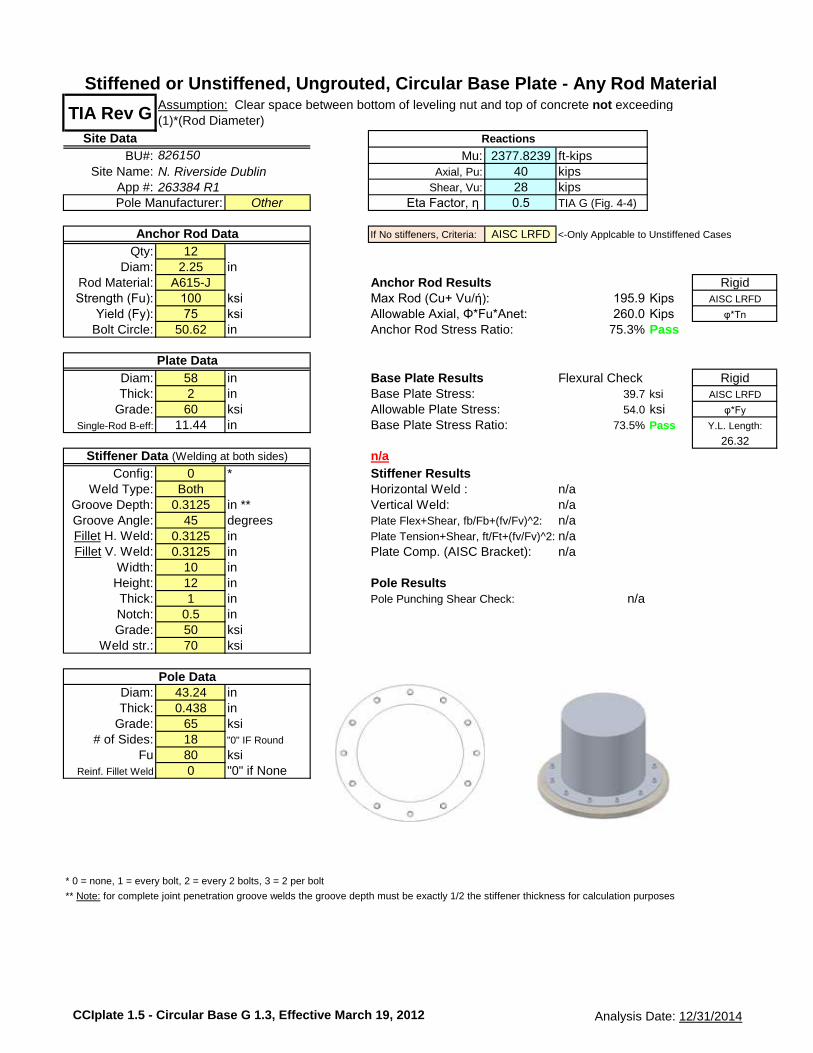
TIA Rev G
Site Data
BU#: 2377.8239 ft-kipsSite Name: 40 kips
App #: 28 kipsOther Eta Factor, η 0.5 TIA G (Fig. 4-4)
If No stiffeners, Criteria: AISC LRFD <-Only Applcable to Unstiffened Cases
Qty: 12Diam: 2.25 in
Rod Material: A615-J Anchor Rod Results RigidStrength (Fu): 100 ksi Max Rod (Cu+ Vu/ή): 195.9 Kips AISC LRFD
Yield (Fy): 75 ksi Allowable Axial, Φ*Fu*Anet: 260.0 Kips φ*Tn
Bolt Circle: 50.62 in Anchor Rod Stress Ratio: 75.3% Pass
Diam: 58 in Base Plate Results Flexural Check RigidThick: 2 in Base Plate Stress: 39.7 ksi AISC LRFD
Grade: 60 ksi Allowable Plate Stress: 54.0 ksi φ*Fy
Single-Rod B-eff: 11.44 in Base Plate Stress Ratio: 73.5% Pass Y.L. Length:
26.32
n/a
Config: 0 * Stiffener ResultsWeld Type: Both Horizontal Weld : n/a
Groove Depth: 0.3125 in ** Vertical Weld: n/aGroove Angle: 45 degrees Plate Flex+Shear, fb/Fb+(fv/Fv)^2: n/aFillet H. Weld: 0.3125 in Plate Tension+Shear, ft/Ft+(fv/Fv)^2: n/aFillet V. Weld: 0.3125 in Plate Comp. (AISC Bracket): n/a
Width: 10 inHeight: 12 in Pole ResultsThick: 1 in Pole Punching Shear Check: n/aNotch: 0.5 inGrade: 50 ksi
Weld str.: 70 ksi
Diam: 43.24 inThick: 0.438 in
Grade: 65 ksi# of Sides: 18 "0" IF Round
Fu 80 ksiReinf. Fillet Weld 0 "0" if None
* 0 = none, 1 = every bolt, 2 = every 2 bolts, 3 = 2 per bolt
** Note: for complete joint penetration groove welds the groove depth must be exactly 1/2 the stiffener thickness for calculation purposes
Stiffener Data (Welding at both sides)
826150
Reactions
Mu:Axial, Pu:
Shear, Vu:
N. Riverside Dublin
Pole Manufacturer:
Assumption: Clear space between bottom of leveling nut and top of concrete not exceeding
(1)*(Rod Diameter)
Stiffened or Unstiffened, Ungrouted, Circular Base Plate - Any Rod Material
263384 R1
Pole Data
Anchor Rod Data
Plate Data
CCIplate 1.5 - Circular Base G 1.3, Effective March 19, 2012 Analysis Date: 12/31/2014

FDH Engineering, Inc., 6521 Meridien Dr. Raleigh, NC 27616, Ph. 919.755.1012, Fax 919.755.1031
Site Name: *Note: Use Anchor Rod Transfer Plate Design Tab in Conjunction
Job No. :Elevation:
Legend
Input
Code (F or G): G Pull DownAnchor Bolts (Yes or No) Yes Pull Down
P (from RISA) 40 kips
V (from RISA) 29 kips
M (from RISA) 3517 ft-kips
Pier Diameter 7 ft
y 25.31 in y new 32 in f'c, caisson's concrete strength 3000 psi
No. Bolts 12 No. Bolts new 3 fy, rebar yield strength 60000 psi
BC 50.62 in BC new 64 in db, diameter of vertical rebar 1 in
I 15297.43487 in4Inew 6,113 in4
vertical rebar cage BC ø 76 in
Bolt Grade A615-75 Pull Down Bolt Grade A193 B7 Pull Down vertical rebar top cover distance 3 in
Thread Form Non-Upset - Thread Form Non-Upset Pull Down τ, Ultimate Hilti Bond Resistance 1.8 ksi
d (in) 2.25 Pull Down d new (in) 2.25 Pull Down Clear Cover 4 in
Ag 3.98 in2Ag new 3.98 in2
Ae 3.25 in2Ae new 3.25 in2
**Note For New Anchor Rods:**
Fy 75 ksi Fy new 105 ksi Williams Bars (Upset)Fu 100 ksi Fu new 125 ksi A722 (Fy=127.7 ksi, Fu=150 ksi)
A615-75 (Fy=75 ksi, Fu=100 ksi)
Itot 21410.71487 in4
T 195.896 kips Tnew 248.381 kips ld (vertical rebar dev. Length) 32.863 in
V 1.933 kips Vnew 1.933 kips ldH (Hilti dev. length) 51.087 in
G/1.5 4.000 in
Tn/Ω 194.5 kips 52.64 inTn/Ω, new 218.9 kips 4.39 ft
øTn 260 kips OK 75.34%øTn, new 325 kips OK 76.42%
Equations: New Anchor Rod Diameter 2.25 in
Selected Pipe Sleeve Area 7.88 in2
T = (M*y*Ag)/Itot-P*(Ag/Atotal) Selected Pipe Sleeve Fy 46 ksi
Rn/Ω (Rev F) or øRn (Rev G) 489.35 k
Tn/Ω = 0.33*Fu*Ag*(4/3) % Capacity (Analysis) 50.76% OK% Capacity (Design) 66.41% OK
Tn = 0.8*Fu*Ae (anchor bolts only) øTn = 0.75*Fu*Ae (non anchor bolts)
I = (No. Bolts/8)*BC2*Ag
No. Existing Rebar
Notes: Existing Rebar BC in
Area rebar in2
*Ag and Ae are taken from AISC 13th Ed. Manual (pg. 7-83) Irebar 0 in4
Itot 6,113 in4
*I calc. will only work for symmetric bolt group, otherwise use CAD Equivalent Area 3.980 in2
Equivalent BC 64.000 in
Total Area 11.94 in2
(works for Rev F also) (assuming new bolts are reinforcement)
Detail Type (hover for detail) d Pull Downŋ 0.5
lar, for Detail Type d only in (top of concrete to bottom of leveling nut) ld = [(fy*ψtψeλ)/(20*√f'c)]*db PER ACI 12.2.2
øRnt 260 kips
øRnv 134.325 kips ldH = (øTn*FS)/(τ*pi*dnew)
øRnm 113.906 kip-inMu 0 kip-in See Worksheet "New (Design Procedure)"
(Pu+Vu/ŋ)/øRnt < 1? 0.768 OK
(only applicable for Detail Type d)(Vu/øRnv)2 +
((Pu/øRnt)+(Mu/øRnm))20.568 OK
Interaction Equation Checks (Rev. G: Section 4.9.9)
Output/
Notes
Existing Rods New Rods
Bearing Strength Check of Anchor Rod Pipe Sleeve
Equivalent BC
Pullout Test Value
190 kips
Anchor Rod Design
Req'd Embedment Length for New Rods
Total Embed. Length of New Bolts
Capacity (%)
Input Cells in Yellow
N. Riverside / Dublin HS
146HQV14000


CCI Foundation Tool Suite - Monopole Pier
CCIFTS 1.2.108.14286 - Phase 1-2 Date: 12/31/2014
BU: 826150
Site Name: N. Riverside Dublin
App Number:
Work Order:
Monopole Drilled Pier
InputCriteria
TIA Revision: G
ACI 318 Revision: 2008
Seismic Category: B
ForcesCompression 40 kips
Shear 29 kips
Moment 1900 k-ft
Swelling Force 0 kips
Foundation Dimensions
Pier Diameter: 7 ft
Ext. above grade: 1 ft
Depth below grade: 17 ft
Material Properties
Number of Rebar: 24 *Steel is unknown
Rebar Size: 8 0.33% code minimum was assumed
Tie Size 4
Rebar tensile strength: 60 ksi
Concrete Strength: 3000 psi
Ultimate Concrete Strain 0.003 in/in
Clear Cover to Ties: 3 in
Soil Profile: 826150
Layer
Thickness
(ft)
From
(ft)
To
(ft)
Unit Weight
(pcf)
Cohesion
(psf)
Friction
Angle
(deg)
Ultimate
Uplift Skin
Friction
(ksf)
Ultimate
Comp. Skin
Friction
(ksf)
Ultimate
Bearing
Capacity
(ksf)
SPT 'N'
Counts
1 3.5 0 3.5 115 0 0 0
2 1 3.5 4.5 115 1700 0 0
3 3 4.5 7.5 115 1700 0 0
4 2.5 7.5 10 115 1200 0 0
5 5 10 15 115 1300 0 0
6 2 15 17 115 1400 0 0
Analysis ResultsConcrete/Steel Check
Soil Lateral Capacity Mu (from soil analysis) 2038.56 k-ft
Depth to Zero Shear: 4.02 ft φMn 3207.14 k-ft
Max Moment, Mu: 2038.56 k-ft RATING: 63.6%
Soil Safety Factor: 1.70Safety Factor Req'd: 1.33
RATING: 78.2% rho provided 0.34
rho required 0.33 OK
Soil Axial Capacity
Skin Friction (k): 173.36 kips Rebar Spacing 8.95
End Bearing (k): 0.00 kips Spacing required 16.00 OKComp. Capacity (k), φCn: 173.36 kips
Comp. (k), Cu: 40.00 kips
RATING: 23.1% Dev. Length required 12.73
Dev. Length provided 43.82 OK
Overall Foundation Rating: 78.2%
(24) - #8
#4 Tie Size
18
'
17
'1
'
7'
3" C.C.
Page 1 of 1

December 31, 2014150.8 Ft Monopole Tower Structural Analysis CCI BU No 826150Project Number 146HQV1400, Application 263384, Revision 1 Page 10
tnxTower Report - version 6.1.4.1
APPENDIX D
MODIFICATION DRAWINGS

PREPARED FOR:
PREPARED BY:
SUBMITTALS
DRAWN BY:
CHECKED BY:
ENG APPV'D:
PROJECT NO:
N. RIVERSIDE / DUBLIN HS
826150
4000 HARD ROAD
DUBLIN, OH 43017
6521 MERIDIEN DRIVE
CROWN CASTLE
SHT.
NO.
DESCRIPTION
SHEET INDEX
ALL DIMENSIONS, MEASUREMENTS, QUANTITIES, PART NUMBERS AND
COAX/ANTENNA PLACEMENTS TO BE FIELD VERIFIED BY CONTRACTOR
PRIOR TO MATERIAL ORDERS AND CONSTRUCTION.
THE MODIFICATIONS DEPICTED ON THESE DRAWINGS ARE BASED ON
THE RECOMMENDATIONS OUTLINED IN THE STRUCTURAL ANALYSIS
COMPLETED BY FDH ENGINEERING, INC., PROJECT NO. 146F4T2400 R1
DATED DECEMBER 5, 2014.
FOR PASSING STRUCTURAL ANALYSIS WITH MODIFICATIONS
IN PLACE SEE FDH ENGINEERING, INC., (PROJECT NO. 146HQV1400),
CROWN SDD WO# 975129 FOR VERIZON APPLICATION 263384 REV. 1
DATED DECEMBER 31, 2014.
THIS MODIFICATION DESIGN HAS BEEN PERFORMED IN ACCORDANCE
WITH THE ANSI / TIA-222-G "STRUCTURAL STANDARD FOR ANTENNA
SUPPORTING STRUCTURES & ANTENNAS"
TITLE SHEET
S-1
TOWER MAPPING:
TOWER ENGINEERING PROFESSIONALS
DRAWING# 113265
PROJECT CONTACTS:
CROWN CASTLE TSA
JASON LAFOLLETTE
(314) 372-2832
FDH PROJECT ENGINEER
BYRON WEBB, EI
(919) 755-1012
FDH ENGINEER (EOR)
DENNIS ABEL
(919) 755-1012
MODIFICATION DRAWINGSFOR A 150.8' MONOPOLE
N. RIVERSIDE / DUBLIN HS
826150
CROWN CASTLE

PREPARED FOR:
PREPARED BY:
SUBMITTALS
DRAWN BY:
CHECKED BY:
ENG APPV'D:
PROJECT NO:
N. RIVERSIDE / DUBLIN HS
826150
4000 HARD ROAD
DUBLIN, OH 43017
6521 MERIDIEN DRIVE
CROWN CASTLE
POST-CONSTRUCTION
MI CHECKLIST
MODIFICATION INSPECTION NOTES:
GENERAL
MI INSPECTOR
GENERAL CONTRACTOR
RECOMMENDATIONS
CANCELLATION OR DELAYS IN SCHEDULED MI
“ ”
CORRECTION OF FAILING MI'S
“ ” “ ”
MI VERIFICATION INSPECTIONS
REQUIRED PHOTOS
CONSTRUCTION
PRE-CONSTRUCTION
MODIFICATION
INSPECTION CHECKLIST
S-2
X
X
X
X
X
N/A
X
X
X
X
X
X
N/A
X
N/A
X
N/A
X
X
X
X

PREPARED FOR:
PREPARED BY:
SUBMITTALS
DRAWN BY:
CHECKED BY:
ENG APPV'D:
PROJECT NO:
N. RIVERSIDE / DUBLIN HS
826150
4000 HARD ROAD
DUBLIN, OH 43017
6521 MERIDIEN DRIVE
CROWN CASTLE
GENERAL NOTES:
CONTRACTOR QUALIFICATION NOTES:
JOB SITE SAFETY & NOTES:
STEEL:
MISC. NOTES:
FABRICATION NOTES:
SUBSTITUTES AND/OR EQUALS:
GENERAL NOTES
S-3
NDE INSPECTION:
PULLOUT TESTING OF POST INSTALLED ANCHOR RODS:
EPOXY/HILTI NOTES:
COLD GALVANIZATION/SURFACE PREPARATION NOTES:
STIFFENER PLATE NOTES:
SURFACE PREPARATION:
STIFFENER PLATE WELDING:

PREPARED FOR:
PREPARED BY:
SUBMITTALS
DRAWN BY:
CHECKED BY:
ENG APPV'D:
PROJECT NO:
N. RIVERSIDE / DUBLIN HS
826150
4000 HARD ROAD
DUBLIN, OH 43017
6521 MERIDIEN DRIVE
CROWN CASTLE
S-4
FOUNDATION NOTES
FOUNDATION CONCRETE:
CONCRETE TESTING:
FOUNDATION REINFORCEMENT:
FOUNDATION NOTES:
PREPARED FOR:
PREPARED BY:
SUBMITTALS
DRAWN BY:
CHECKED BY:
ENG APPV'D:
PROJECT NO:
N. RIVERSIDE / DUBLIN HS
826150
4000 HARD ROAD
DUBLIN, OH 43017
6521 MERIDIEN DRIVE
CROWN CASTLE
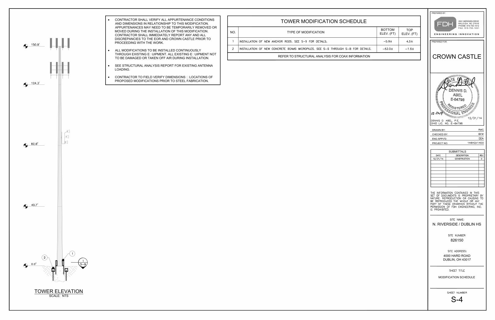
MODIFICATION SCHEDULE
S-4
CONTRACTOR SHALL VERIFY ALL APPURTENANCE CONDITIONS
AND DIMENSIONS IN RELATIONSHIP TO THIS MODIFICATION.
APPURTENANCES MAY NEED TO BE TEMPORARILY REMOVED OR
MOVED DURING THE INSTALLATION OF THIS MODIFICATION.
CONTRACTOR SHALL IMMEDIATELY REPORT ANY AND ALL
DISCREPANCIES TO THE EOR AND CROWN CASTLE PRIOR TO
PROCEEDING WITH THE WORK.
ALL MODIFICATIONS TO BE INSTALLED CONTINUOUSLY
THROUGH EXISTING EQUIPMENT. ALL EXISTING EQUIPMENT NOT
TO BE DAMAGED OR TAKEN OFF AIR DURING INSTALLATION.
SEE STRUCTURAL ANALYSIS REPORT FOR EXISTING ANTENNA
LOADING.
CONTRACTOR TO FIELD VERIFY DIMENSIONS & LOCATIONS OF
PROPOSED MODIFICATIONS PRIOR TO STEEL FABRICATION.
TOP
ELEV. (FT)
TYPE OF MODIFICATIONNO.
TOWER MODIFICATION SCHEDULE
BOTTOM
ELEV. (FT)
TOWER ELEVATION
SCALE: NTS

PREPARED FOR:
PREPARED BY:
SUBMITTALS
DRAWN BY:
CHECKED BY:
ENG APPV'D:
PROJECT NO:
N. RIVERSIDE / DUBLIN HS
826150
4000 HARD ROAD
DUBLIN, OH 43017
6521 MERIDIEN DRIVE
CROWN CASTLE
SITE PLAN
S-6
PLAN
NTSS-6
1
PLAN VIEW
SITE PLAN
CONTRACTOR TO PERFORM SITE VISIT TO DETERMINE
INTERFERENCES PRIOR TO CONSTRUCTION.
CONTRACTOR RESPONSIBLE FOR REPLACING ANY
GROUNDING MATERIAL THAT MAY NEED TO BE REPLACED OR
REMOVED DUE TO PROPOSED INSTALLATION.
CONTRACTOR MAY BE REQUIRED TO TEMPORARILY
RELOCATE ICE BRIDGES AND COAX DURING CONSTRUCTION.
COAX MUST NOT BE DAMAGED OR TAKEN OFFLINE AT ANY
GIVEN TIME DURING CONSTRUCTION.
CONTRACTOR TO FIELD VERIFY LOCATION OF ALL UTILITY
LINES BELOW GRADE PRIOR TO CONSTRUCTION.
CONTRACTOR TO FIELD VERIFY ORIENTATION OF EXISTING
FOUNDATION PRIOR TO CONSTRUCTION.
CONTRACTOR MAY BE REQUIRED TO REMOVE A PORTION OF
THE CHAIN LINK FENCE. CONTRACTOR MUST REPLACE ANY
DISTURBED FENCE AFTER CONSTRUCTION.

PREPARED FOR:
PREPARED BY:
SUBMITTALS
DRAWN BY:
CHECKED BY:
ENG APPV'D:
PROJECT NO:
N. RIVERSIDE / DUBLIN HS
826150
4000 HARD ROAD
DUBLIN, OH 43017
6521 MERIDIEN DRIVE
CROWN CASTLE
S-7
CONCRETE BEAM &
MICROPILE DETAILS I
DETAIL
SCALE: 1/2" = 1'-0"S-7
1
PLAN VIEW
CONCRETE BEAM AND MICROPILE LAYOUT
PART
NO.
DESCRIPTIONSHAPE
CONCRETE BEAM & MICROPILE
MATERIAL LIST
QTY.* LENGTH
PISTON PLUGS SHOULD BE USED IN ALL APPLICATIONS WHERE INJECTION ADHESIVE IS
REQUIRED.
CONTRACTOR TO PROVIDE ENGINEER OF RECORD WITH PICTURES OF REBAR LAYOUT
FOR APPROVAL PRIOR TO POURING CONCRETE.
CONTRACTOR TO PROVIDE TEMPORARY BRACING FOR BASE OF TOWER DURING
ENTIRE BASE FOUNDATION MODIFICATION.

PREPARED FOR:
PREPARED BY:
SUBMITTALS
DRAWN BY:
CHECKED BY:
ENG APPV'D:
PROJECT NO:
N. RIVERSIDE / DUBLIN HS
826150
4000 HARD ROAD
DUBLIN, OH 43017
6521 MERIDIEN DRIVE
CROWN CASTLE
S-8
CONCRETE BEAM &
MICROPILE DETAILS II
DETAIL
SCALE: 3/4" = 1'-0"S-8
2
SECTION VIEW
CONCRETE BEAM AND MICROPILE LAYOUT
DETAIL
SCALE: 3/4" = 1'-0"S-8
3
ELEVATION VIEW
CONCRETE BEAM AND MICROPILE LAYOUT
DETAIL
SCALE: 3/4" = 1'-0"S-8
1
PLAN VIEW
CONCRETE BEAM AND MICROPILE LAYOUT

PREPARED FOR:
PREPARED BY:
SUBMITTALS
DRAWN BY:
CHECKED BY:
ENG APPV'D:
PROJECT NO:
N. RIVERSIDE / DUBLIN HS
826150
4000 HARD ROAD
DUBLIN, OH 43017
6521 MERIDIEN DRIVE
CROWN CASTLE
S-9
ANCHOR ROD
INSTALLATION DETAILS
ANCHOR ROD MATERIAL LIST
ELEVATIONPART. NO QTY. DESCRIPTION
CONTRACTOR TO PROVIDE PHOTOS OF THE ANCHOR ROD HOLES TO EOR PRIOR TO
INSTALLING NEW ANCHOR RODS. PHOTOS MUST SHOW THE DEPTH AND DIAMETER OF
ANCHOR ROD HOLES.
PISTON PLUGS TO BE USED IN ALL INJECTION ADHESIVE APPLICATIONS
CONTRACTOR TO INSTALL ANCHOR ROD TO A MIN. DEPTH OF 5'-6" BELOW TOP OF
CAISSON AND FILL WITH HILTI HIT-RE 500-SD INJECTION ADHESIVE.
DESCRIPTIONQTY.PART. NO.
MATERIAL LIST (MK-1)
SECTION
NTSS-9
1
SECTION VIEW
ANCHOR ROD INSTALLATION
ANCHOR ROD ASSEMBLY WELD DETAIL
ELEVATION VIEW
ELEVATION
NTS
2
S-9
ANCHOR ROD ASSEMBLY
TOP & SIDE VIEW
SECTION
NTS
MK-1
S-9
WASHER PLATE
TOP VIEW
DETAIL
NTS
MK-2
S-9


![CellMax Antenna - 201105 [Compatibility Mode]](https://static.fdocuments.in/doc/165x107/5477b38ab4af9f76108b4919/cellmax-antenna-201105-compatibility-mode.jpg)