
DATASHEET - RGB Automatyka | centrum automatyki …€¦ · Monitoring without activating pulse...
86
RGB ELEKTRONIKA AGACIAK CIACIEK SPÓŁKA JAWNA Jana Dlugosza 2-6 Street 51-162 Wrocław Poland [email protected] +48 71 325 15 05 www.rgbautomatyka.pl www.rgbelektronika.pl DATASHEET www.rgbautomatyka.pl www.rgbelektronika.pl OTHER SYMBOLS: EVS9224-E EVS9224E, EVS9224 E, EVS9224-E LENZE
Transcript of DATASHEET - RGB Automatyka | centrum automatyki …€¦ · Monitoring without activating pulse...

RGB ELEKTRONIKA AGACIAK CIACIEKSPÓŁKA JAWNA Jana Dlugosza 2-6 Street51-162 WrocławPoland
[email protected] +48 71 325 15 05
www.rgbautomatyka.pl
www.rgbelektronika.pl
DATASHEET
www.rgbautomatyka.plwww.rgbelektronika.pl
OTHER SYMBOLS:
EVS9224-E
EVS9224E, EVS9224 E, EVS9224-E
LENZE

YOUR PARTNER IN MAINTENANCE
At our premises in Wrocław, we have a fully equipped servicing facility. Here we perform all the repair works and test each later sold unit. Our trained employees, equipped with a wide variety of tools and having several testing stands at their disposal, are a guarantee of the highest quality service.
OUR SERVICES
ENCODERS
SERVO DRIVERS
LINEAR ENCODERS
SERVO AMPLIFIERS
CNC MACHINES
MOTORS
POWER SUPPLIERS
OPERATOR PANELS
CNC CONTROLS
INDUSTRIAL COMPUTERS
PLC SYSTEMS
Repair this product with RGB ELEKTRONIKA ORDER A DIAGNOSIS
Buy this product at RGB AUTOMATYKA BUY

EDB9200_E/GB00375316
Antriebstechnik
Operating Instructions
Servo controller9200 series

These Operating Instructions are valid for the controllers with the nameplate data:
9212 E.5x9215 E.5x9217 E.5x
9222 E.5x.5x9223 E.5x.5x9224 E.5x.5x9225 E.5x.5x9226 E.5x.5x9227 E.5x.5x9228 E.5x.5x
Controller type
Enclosure IP20
Hardware version + index
Software version + index
Corresponds to the German edition of 05/18/1995
Edition of: 05/18/1995
Date of print: 05/29/1995
1
How to use these OperatingInstructions...
These Operating Instructions are divided into three parts:
• Planning and installationThis part comprises the technical data of the supply modules,the axis modules and of accessories available for the 9200series (e. g. motors), instructions for installation and wiring anddescriptions of the drive connections.
• Parameter settingDescribes the basics of parameter setting and informs aboutcommissioning, important functions and the operation via serialinterface. At the end of this part you will find a comprehensivecode table and a signal flow chart.
• ServiceExplains error messages and gives hints for trouble-shooting.
To locate information on specific topics, simply refer to the table ofcontents at the beginning and to the index at the end of theoperating instructions.
A series of different symbols provide quick reference and highlightimportant items.
NoteThis symbol refers to items of information intended to facilitateoperation.
CautionNotes which should be observed to avoid possible damage to ordestruction of equipment.
WarningNotes which should be observed to avoid health risks to theoperating personnel.
Fehler! Esist nichtmöglich,durch die
B b it

2
Safety informationfor electrical equipment used in industrial power installations.
The electrical devices and machines described are equipment to beused in industrial power installations. This equipment incorporateshazardous parts that are live, moving or rotating during operation.Severe personal injury or damage to equipment may occur if e. g.any required enclosures or covers are inappropriately removed orthe equipment is insufficiently serviced.
The personnel responsible for the safety of the equipment musttherefore ensure that:
• only qualified personnel are permitted to install, operate andmaintain the devices
• these Operating Instructions and any other documentationabout the equipment are consequently observed and alwaysavailable to the personnel working with the equipment.
• non-qualified personnel is prohibited from working with theequipment or in its vicinity.
• the system is installed in accordance with local regulations.
A qualified person must by training be familiar with all relevantstandards and safety regulations and therefore be authorized toperform the required work (For further details cf. IEC 364).
These safety instructions do not claim to be exhaustive. Should anyquestions or problems occur, please contact your nearest Lenzerepresentative.
The information given in these Operating Instructions refer to thespecified hardware and software versions of the equipment.
The specifications, processes and ciruitry described in theseOperating Instructions are for guidance only and must be adaptedto your specific application.
Lenze cannot be held responsible for the applicability of theprocesses and circuitry indicated.
The specifications in these Operating Instructions describe, notguarantee the features of the equipment.
Hardware, software and documentation of the equipment havebeen carefully checked by Lenze. Faultlessness cannot beguaranteed.
Subject to technical alterations.
3
Content
Planning and Installation
1. Features 5
2. Technical data 6
2.1. General data 62.2. Unit-specific data 62.2.1. Rated data of supply modules 62.2.2. Rated data of axis modules 72.3. Dimensions 82.4. Extension of delivery 82.5. Application as directed 82.6. Manufacturer's certification 9
3. Installation 10
3.1. Mechanical installation 103.2. Electrical installation 113.2.1. Combination of several axis modules with one supply module 123.2.2. Screening and earthing 143.2.3. Radio interference suppression 16
4. Drive connections 17
4.1. Power connections 174.1.1. Mains and motor connection 174.1.2. External brake resistor 184.2. Control connections of supply module 204.2.1. Overheat of internal brake resistor (9210 X1) 204.2.2. Mains and DC-bus monitoring (9210 X3) 204.2.3. State bus 214.3. Control connections axis module 224.3.1. Control terminals 224.3.2. Analog input and outputs 224.3.3. Digital inputs and outputs 23
5. Application examples 26
5.1. Variant with integrated positioning module 2211PP 265.2. Wiring with positioning control SX-1 285.2.1. Diagram 1: Mains supply 285.2.2. Diagram 2: Control circuit 230V 295.2.3. Diagram 3: Control circuit 24V 305.2.4. Diagram 4: Control connections 9200 - SX1 315.2.5. Diagram 5: Control connections SX1 32
6. Accessories 33
6.1. External brake resistors 336.2. Mains chokes 336.3. RFI filter 346.4. External fuses 346.5. System cables 346.5.1. System cables for control terminal block X5 346.5.2. System cables for master frequency selection X2 and incremental encoder outputX4 356.5.3. System cables for resolver X3 366.5.4. System cables for power supply of servo motors 376.5.5. System calbes for supply fo fan and brake 386.6. Motors 39

4
1. LCD display 40
1.1. Key functions 401.2. Plain-text display 40
2. Basics of parameter setting 41
2.1. Change parameters 412.2. Save parameters 422.3. Load parameter 422.4. Examples 43
3. Commissioning 45
3.1. Basic parameter setting 453.2. Input of motor nameplate data 473.3. Setting of operating parameters 48
4. Additional functions 50
4.1. Mains failure detection with DC-bus control 504.1.1. Requirements 504.1.1. Wiring 524.1.2. Setting 534.2. Homing mode 564.3. Further additional functions 57
5. Serial interfaces 58
5.1. LECOM1 interface X1 585.2. LECOM status messages 595.3. Table of attributes 60
6. Code table 63
7. Signal flow chart axis modules 72
1. Monitoring messages 74
1.1. Monitoring without activating pulse inhibit 741.2. Monitoring with activating pulse inhibit 741.3. Monitoring with TRIP setting 74
2. LED displays 78
2.1. LED supply module 782.2. LED axis module 78
3. Checking the power stage 79
3.1. Checking the mains rectifier 793.2. Checking the output stage 79
Index 83

5
Planning and installation
1. Features
The 9200 controller series comprises 3 supply modules (types9212, 9215 and 9217) and 7 servo modules (types 9222-9228 withmotor peak currents ranging from 8 to 82 A) for asynchronousservo motors.
• Digital control by 16-bit microcontroller and 3 ASICs
• Field-orientated vector controlled current
• Four-quadrant operation, any speed and torque direction
• Inverter with IGBTs
• Selectable chopper frequency either low noise 8kHz or silent16kHz
• Supply and axis modules can be combined for single or multi-axis operation
• Efficient energy exchange by means of DC-bus for multi-axisoperation
• Controlled operation even during mains interruption.
• Supply modules with integrated brake chopper and brakeresistors
• Short-circuit protected inverter outputs
• When using the specified mains chokes, the units comply withthe overvoltage class 2 according to VDE 0160
• I x t monitoring as overload protection for the inverter
• Parameter setting and diagnosis via keypad and 2-line LCDdisplay in plain text German, English, and French language
• Control parameters can be modified ON-LINE
• Isolated digital inputs and outputs for 24V-PLC level
• Electronic incremental encoder simulation for use by otherdrives
• Master frequency input for positioning, master/slave operationor angular synchronization
• Drift free standstill in the case of master frequency input orquick stop QSP
• Serial interface LECOM A/B (RS232 and RS 485) forparameter setting, control and diagnosis
• Enclosure IP20
• Variants with additional modules are available
• Approvals: UL 508, File no. 132659VDE 0160, VDE reg. no. 1799

6
2. Technical data
2.1. General data
Enclosure Steel sheet housing, IP20 to DIN 40050
Noise immunity: Severity 4 to IEC 801-4
Influence of installation height onrated current:
1000 m: 100% rated current2000 m: 95% rated current3000 m: 90% rated current4000 m: 85% rated current
Ambient temperature 0 °C...+45 °C during operation-25 °C...+55 °C during storage-25 °C...+70 °C during transport
Permissible humidity relative humidity 80%, no condensation
Permissible pollution Pollution strength 2 to VDE 0110, part 2.Do not expose units to corrosive or explosive gases.
2.2. Unit-specific data
2.2.1. Rated data of supply modulesSupply module type 9212_E 9215_E 9217_E
Order no. 33.9212_E 33.9215_E 33.9217_E
Mains voltage [V] 3 x 480; 50 - 60 Hzpermissible range 3 x 330...528 ± 0%;
DC-bus voltage(at rated current)
[V] 1.35 x Vmains
Mains current [Aeff] 6 20 40
Permanent power1)
(at Vmains = 3 x 480 V)[kW] 4.9 16.5 33
Peak power(t=5 s)
[kW] 12 37 60
Permanent brake power (with int.brake resistor)
[W] 250
Permanent brake power (withappropriate ext. brake resistor)
[kW] 4.9 16.5 33
Peak brake powerwith int. or ext. brake resistor
[kW] 19.4 51.1 66.1
min. permissible resistance for int.or ext. brake resistor
[Ω] 29 11 8.5
Power loss (without brake resistor) [W] 110 110 110
Weight [kg] 9.0 10.5 11.0
1) With low mains voltages, the permissible permanent power is reduced to Pzul = Pn ⋅ Vmains / 480 V

7
2.2.2. Rated data of axis modulesAxis module type 9222_E 9223_E 9224_E 9225_E
Order no. 33.9222_E 33.9223_E 33.9224_E 33.9225_E
Output current(fch = 8 kHz)
[Aeff] 4.5 5.5 13.5 18
Output current(fch = 16 kHz)
[Aeff] 2.3 2.9 6.9 9.5
Peak current(for t = 5 s at fch = 8 kHz;for t = 2.5 s at fch = 16 kHz)
[Aeff] 8 10 24 33
Permanent power(VA = 3 x 480 V and fch = 8 kHz)
[kVA] 3.7 4.5 11.2 14.9
Permanent power(VA = 3 x 480 V and fch = 16 kHz)
[kVA] 1.9 2.4 5.7 7.9
Peak power(VA = 3 x 480 V)
[kVA] 6.6 8.3 19.9 27.4
Output voltage VA [V] 3 x 0...Vmains
Field frequency [Hz] 0... ± 300
Speed [min-1 ] 0... ± 8000
Power loss at permanent power [W] 200 250 340 510
Power loss at controller inhibit [W] 45 45 45 125
Weight [kg] 9.2 9.5 9.5 20.5
Type 9226_E 9227_E 9228_E
Order no. 33.9226_E 33.9227_E 33.9228_E
Output current(fch = 8 kHz)
[Aeff] 25 32 46
Output current(fch = 16 kHz)
[Aeff] 13 16.5 23.5
Peak current(for t = 5s at fch = 8kHz;for t = 2.5 s at fch = 16kHz)
[Aeff] 45 57 82
Permanent power(VA = 3 x 480 V and fch = 8 kHz)
[kVA] 20.2 26.6 38.2
Permanent power(VA = 3 x 480 V and fch = 16 kHz)
[kVA] 10.8 13.7 19.5
Peak power(VA = 3 x 480 V)
[kVA] 37.4 47.3 68.1
Output voltage VA [V] 3 x 0...Vmains
Field frequency [Hz] 0... ± 300
Speed [min-1 ] 0... ± 8000
Power loss at permanent power [W] 640 800 1000
Power loss at controller inhibit [W] 125 125 125
Weight [kg] 21 22 22

8
2.3. Dimensions
Type a[mm]
b[mm]
c[mm]
d[mm]
e[mm]
g[mm]
9212 - 92179222 - 9224
125 440 95 425 300 5
9225 - 9228 290 440 250 425 300 5
2.4. Extension of delivery
• Axis module or supply module
• Accessory kit (busbars, State-bus line, control terminals)
• Operating Instructions
2.5. Application as directed
The units of the 9200 series are electrical units which are designedfor the application in control cabinets in industrial powerinstallations. They are designed for variable speed operations withthree-phase AC motors.

9
2.6. Manufacturer's certification
We hereby certify that the below listed electronic controllers arecontrol components for variable speed motors intended for theassembly into machines or together with other components to forma machine. According to the "Council directive ... relating tomachinery" 89/392/EWG, our controllers are no machines.
The Operating Instructions supplied together with the controllersgive advice and recommendations for the installation and use of theelectronic equipment.
As long as the conformity with the protection and safetyrequirements of the "Council directive ... relating to machinery"89/392/EWG and its amendment 91/368/EWG is not proved,operation of the machine is prohibited.
The measures required for typically configurated controllers tocomply with the EMC limit values are indicated in the OperatingInstructions. The electromagnetic compatibility of the machinedepends on the method and accuracy of the installation. The useris responsible for the compliance of the machine with the "Councildirective ... relating to electromagnetic compatibility" 89/336/EWGand its amendment 92/31/EWG.Considered standards and regulations:
• Electronic equipment for use in electrical power installations andtheir assembly into electrical power installations: DIN VDE 0160,5.88 (pr EN 50178)
• Standards for the erection of power installations:DIN VDE 0100
• IP - enclosures: EN 60529, 10.91
• Base material for printed circuits:DIN IEC 249 part 1, 10.90; DIN IEC 249 part 2-15, 12.89
• Printed circuits, printed boards:DIN IEC 326 part 1, 10.90; EN 60097, 9.93
• Creepage distances and clearances:DIN VDE 0110 part 1-2, 1.89; DIN VDE 0110 part 20, 8.90
• Electrostatic discharge (ESD):prEN 50082-2, 8.92, IEC 801-2, 9.87 (VDE 0843, part 2)
• Electrical fast transient interference (Burst):prEN 50082-2, 8.92, IEC 801-4, 9.87 (VDE 0843, part 4)
• Surge immunity requirements: IEC 801-5,10.93
• Radio interference suppression of electrical equipment andplants:EN 50081-2, 3.94; EN 55011 (VDE 0875, part 11,7.92)
• Radio interference suppression of radio frequency equipmentfor industrial purposes: VDE 0871, 6.78

10
3. Installation
3.1. Mechanical installation
• The units are designed as housing units with enclosure IP20.
• Install the units vertically with the power terminals at the top.
• Ensure a free space of 100 mm at both the bottom and the top.
Caution!When working with the maximum brake power, the temperature of the output air ofthe supply modules can reach up to 120°C.
• The axis modules should be installed at the same height at the righthand side ofthe supply module:− If the axis modules have different power outputs, the more
powerful axis module must be placed directly next to thesupply module.
• The interface connectors X1 to X4 and other terminals must becovered with the supplied dust protectors or unused connectorswhen not used.

11
3.2. Electrical installation
• The breakaway torque for the power terminals is 2.3 Nm(20 lb in). Marking of terminals:at 921X: +UG, -UG, RBr, L1, L2, L3at 922X: +UG, -UG, U, V, W
Supply modules
• Without additional protective measures (e.g. zeroing) the unitsmay not be connected to a mains with e.l.c.b. (VDE0160/05.88). In the event of an earth fault, a DC component inthe fault current can prevent the release of the e.l.c.b.
• Operate the supply module with assigned mains choke.
• Power inputRecommended cable diameter and number of cores
Supply module 9212 9215 9217
Number of cores 4(L1,L2,L3,PE)
4(L1,L2,L3,PE)
4(L1,L2,L3,PE)
Cable diameter [mm²]or
1,5 4 10
AWG 14/15 10/11 6/7
Protect input cables according to their diameter with adaptedcable protection fuses.
• Protection of the input rectifier:− Total protection with external very quick acting fuses in the
mains input (see chapter "Accessories")− If total protection is not required: The normal cable protection fuses or miniature circuit
breakers which are adapted to the cable diameter offersufficient protection.
• The peak power of the supply module must be equal to orhigher than the total peak power of the connected axis modulesand the rated power of the suply module must also be equal toor higher than the total permanent power of the axis module(see chap. 3.2.1).
Note
The supply modules 921x hardware version E.4x onwards described in theseOperating Instructions may only be used in combination with the axis modules ofthe hardware version E.4x and higher.
Axis modules
• Connect only one motor to each axis module.
• The cable diameter of the motor cables must correspond to therated current of the motor.Protection by means of:− cable protection fuses or− adapted motor protection relay
• Ensure motor protection:− use motor protection relay and monitor the thermostat of the
motor.
• The connected motor may not be operated when the controlleris enabled, except for safety shutdown.

12
3.2.1. Combination of several axis modules with one supply modulePlease note the following conditions when combining several axismodules with one supply module:
• The State-bus (X6) can supply max. 10 axis modules.
• The sum of the total capacity of the DC-bus may not exceed acertain value (see chart):The permissible total capacity depends on the interval betweentwo closing operations and the mains voltage. The total capacityis the sum of the capicities of the supply module and the axismodules.− For intervals between two closing operations longer than
15 min, the max. permissible capacities are applied.
DC-bus capacities of the 9200 series
Type 9212 9215 9217 92229223
9224 92259226
92279228
CZK [µF] 235 705 1175 235 340 1100 2200
Permissible total capacity depending on the interval between two closingoperations and the mains voltage
9215; 9217 V mains=400V-480V
9212 V mains=400V
9212 V mains=480V
0
1000
2000
3000
4000
5000
6000
7000
8000
9000
0 1 2 3 4 5 6 7 8 9 10 11 12 13 14 15
Switch-on distance / min
C (
tota
l) /
µF

13
• When selecting the power of the supply module, proceed asfollows to find out about the required input power.1. Determine the power profile of all axis modules connected to
the DC-bus by means of the process profile and the loadtorques during a system cycle.
2. The power losses are stated in the technical data, for unitsthe losses are stated during rated power and for motors thepower loss during rated operation. These losses areassumed to be constant during the whole cycle.
3. Find out the resultant powr by adding the power losses andthe power profiles:calculate a positive motor powerand a negative generator power.
4. Determine the effective power during the system cycle:Do not calculate a negative resultant power (generatorpower). These ranges can taken into consideration whencalculating the effective brake power.
5. Select the supply module according to the effective powerduring a system cycle:Please note that the supply module must have enoughcapacity to supply the effective peak power and that, in theevent of mains voltage reductions, the permissible power ofthe supply module will be reduced according to the reductionof the mains voltage.
6. If the calculated effective permanent power exceeds thepermissible value of the supply module 9217:Subdivide the DC-bus sets and install further supplymodules.

14
3.2.2. Screening and earthingIn order to avoid radio interference, care must be taken with the design andconnection of digital drives to avoid EMC disturbances during operation.
Digital drives are not more vulnerable to interference than analog drives, but theeffect is generally different. Interference of analog devices becomes obvious asirregularities in speed. Interference of digital drives may causeprogram errors; therefore it is important that the drives are inhibitedimmediately when interference occurs. This is done by setting theTRIP function (CCr).
In order to avoid these problems, care must be taken with ground(GND), protective earth (PE) connections as well as screening.
• Screen control cables and motor cables.
• Ensure effective screening:− a non-earthed conductior should be used to maintain screen
integrity where cahbles are interrupted (terminal strips,relays, fuses).
Caution!To increase the EMC (electromagnetic compatibility), the reference GND isconnected to the protective earth (PE) inside the drive.
To ensure an optimum interference suppression, the screening and the GND-PE-connection is made differently for single drive and multi drivenetworks.
Single drive
• Connect the screen of the control cables to PE of the drive atone end to avoid earth loops.
• GND and PE are connected by a jumper inside the drive.
• In case of firmly installed computer connections, a mainsisolation (e.g. Lenze Converter 2101) is mandantory betweencomputer and axis module.
• The screens of the motor cables− should be as large as possible.− connected to the two sides.
Fehler! Esist nichtmöglich,durch die
B b it
15
Multi drive networking
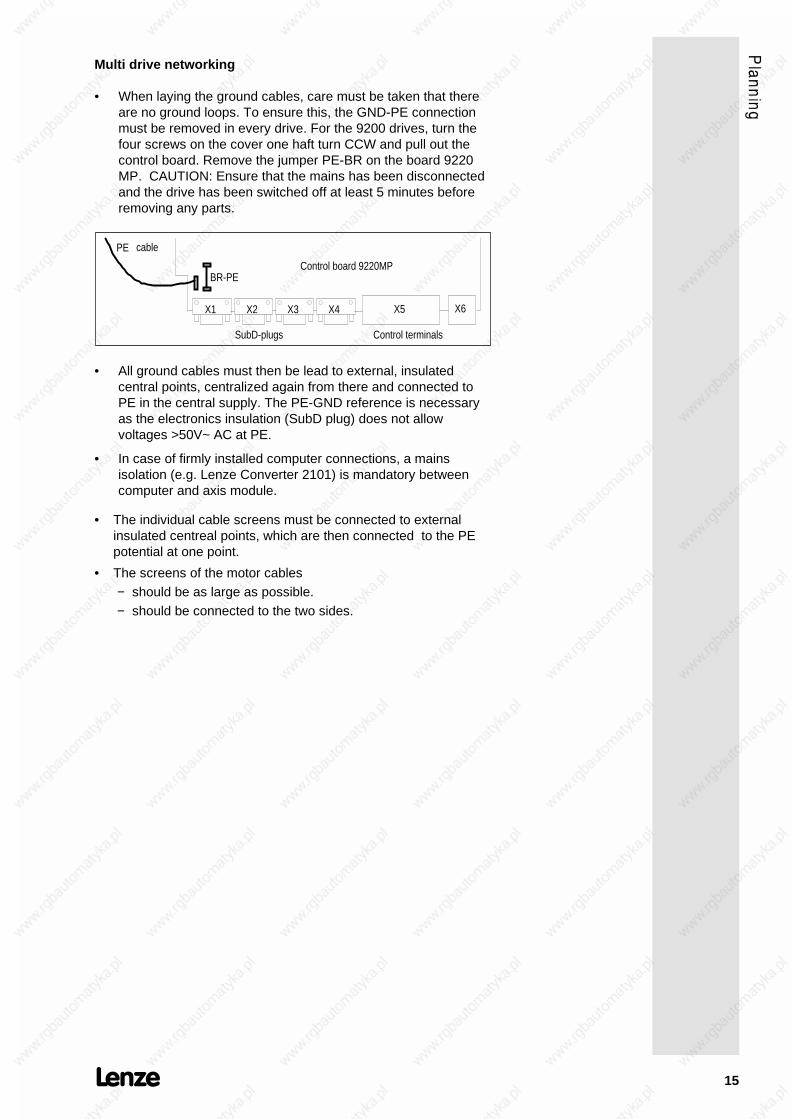
• When laying the ground cables, care must be taken that thereare no ground loops. To ensure this, the GND-PE connectionmust be removed in every drive. For the 9200 drives, turn thefour screws on the cover one haft turn CCW and pull out thecontrol board. Remove the jumper PE-BR on the board 9220MP. CAUTION: Ensure that the mains has been disconnectedand the drive has been switched off at least 5 minutes beforeremoving any parts.
BR-PE
PE cable
Control board 9220MP
SubD-plugs
X1 X2 X3 X4 X5 X6
Control terminals
• All ground cables must then be lead to external, insulatedcentral points, centralized again from there and connected toPE in the central supply. The PE-GND reference is necessaryas the electronics insulation (SubD plug) does not allowvoltages >50V~ AC at PE.
• In case of firmly installed computer connections, a mainsisolation (e.g. Lenze Converter 2101) is mandatory betweencomputer and axis module.
• The individual cable screens must be connected to externalinsulated centreal points, which are then connected to the PEpotential at one point.
• The screens of the motor cables− should be as large as possible.− should be connected to the two sides.
16
3.2.3. Radio interference suppressionAccording to § 13 and § 14 of the legislation of the EuropeanCommunity relating to the electromagnetic compatibility of devices(EMVG v. 09.11.92) the national standards and regulations are onlyinterim standards vilid until December 31, 1995. In addition, theharmonized European standards can be fulfilled following therecommendations below. Measures against radio interferencesuppression depend on the site of the device to be installed:
Previous national standardsThe application without radio interference suppression in electricalsystems within connected working areas or industrial premises canonly be allowed if, outside the industrial premises, the limit valuesaccording to VDE 0871/6.78, class B are not exceeded (Generalallowance according to the standard on the operation of high-frequency devices of December 14, 1984, official no. 1045/1046).For operation within residential areas or when exceeding the limitvalue class B outside of industrial premises, radio interferencesuppression according to VDE 0871, limit value class B is required.
Future hormonized standardsThe standard prEN 50081-2 is valid for the radio interferencesuppression.It refers to standard EN 55011 (VDE 0875, part 11, limit value classA and B).
• Within industrial premises, which are not connected to the publiclow-voltage supply, the limit values to EN 55011, limit valueclass A apply.
• Within residential areas or industrial premises, which areconnected to the plublic low-voltage supply, the limit values toEN 55011, limit value class B apply.
Radio interference suppression to EN 55011, limit value classA or B, can be achieved by:
• Using a suitable mains filter and screening of motor cables,brake resistor cables and the power cable between mains filterand inverter (for recommended mains filters see "Accessories").

17
4. Drive connections
4.1. Power connections
4.1.1. Mains and motor connectionCaution!All power terminals carry mains potential up to 5 minutesafter mains disconnection.
The DC-bus terminals +UG -UG and the PE terminals of the supplyand axis module must be connected by means of busbars(accessory kit).

18
4.1.2. External brake resistorTo increase the permanent brake power, an external brake resistorwith a higher permanent power can be installed instead of theinternal resistor. In this case, the internal brake resistor must bedisconnected.
Disconnection of the internal resistor:
1. Remove right side of the supply module housing 9210, whenno voltage is applied.
2. Disconnect spade plug.
3. Connect spade plugs to tabs on the housing.
4. Close housing again.
in te rna lb rake resisto r
1.
2.3.
4.
The external brake resistor must be connected to the powerconnections +UG and RBR at the supply modules 9210. It isrecommended to exclusively use resistors with integrated overloadprotection which disconnect the mains supply in case of overload(for recommended resistors see chapter "Accessories"). Thesurface temperature of the resistor may reach 360°C.
Caution!When using brake resistors without overload protection, the resistors may burn dueto a fault (e.g. mains overvoltages >528V, application specific overload or internalfaults).

19
Wiring of brake resistor
CautionK1 must additionally set controller enable!
Wiring when using the internal brake resistor
Wiring when using the external brake resistor

20
4.2. Control connections of supply module
4.2.1. Overheat of internal brake resistor (9210 X1)The thermal contact (capacity 230V/10A) of the internal brakeresistor can be accessed via the connector X1 of the supplymodule. It can be used to switch off the mains in case of overloadof the internal brake resistor (see also: External brake resistor).
Caution!Unlike previous models of this series, the connector X1 of the supply module doesnot have to be bridged any more. This connector cannot be used for the monitoringof an external thermal contact and the like! To protect the inverter, wiring accordingto figure "Wiring using the internal brake resistor" (page 19) is necessary.
4.2.2. Mains and DC-bus monitoring (9210 X3)At X3 of the power supply module several signals are available,that give information about the status of the mains. The wiring ofthis terminal is not necessary to make the device work. If thesoftware feature mains failure with DC-bus controlling is required,the terminals X3,1 and X3,3 must be wired. By using an external 24V supply there is an optoisolated signal of mains failure at terminalX3,5.For further information see: Parameter setting, page 50.

21
4.2.3. State busBy means of the state bus X6, the supply module gives statusinformation like ready, overvoltage, and heat sink or resistorovertemperature to the connected axis modules. The four state buscables must be taken from the supply module to the axis modules.The terminals in the axis module which are next to each other areinternally bridged.
When the modules are ready to operate, the following levels areapplied at the terminal of the state bus:
• Temp -> GND : approx. 0...2 V
• RDY -> GND : approx. 0...2 V
• Vmax GND : more than 2 V
These levels can only be measured when the state bus isconnected between the supply module and the axis modules.
9210 9 22 0 922 0
U m ax
R D Y
T em p
G N D U m ax
R D Y
T em p
G ND
U m a x
R D Y
T em p
G ND
S tate B us S ta te B us S ta te B us
X 6 X 6 X 6

22
4.3. Control connections axis module
4.3.1. Control terminalsPin assignment of the control terminal block X5
4.3.2. Analog input and outputsAnalog set value selectionFor analog set value provision, two inputs are available, either asspeed or torque set value provision (for selection see C005configuration). The bipolar input is a differential input..
1 2 7 8 9
AS
E
-
-
X5 X5
68kOhm
82kOhm
R304
44kOhm
R306
44kOhm
100kOhm100kOhm
68kOhm
82kOhm
Master voltage0...+10V
Master voltage-10...+10V
a) bipolar set value selection b) unipolar set value selection
Set valuepotentio-meter10 kOhm/lin.
Monitor outputsThe terminals 62 and 63 of the control terminals block X5 transforminternal digital control signals into analog output signals. Theresolution is 8 bit. The signals are updated every 2ms. Themaximum monitor output current capacity is 2mA.
Output Terminal Signal Range Level
Monitor 1 X 5 62 Actual speed value adjustable via C153/C154 -10V...+10V
Monitor 2 X 5 63 Torque set value -Mmax...+Mmax -10V...+10V

23
4.3.3. Digital inputs and outputsExternal 24 V supply Internal 15 V supply
Caution!GND is internally connected to PEvia jumper BR-PE.
Caution!Bridge signals X5,39 and X5,40.
-
QSP
R L JOG
TRIP
SET
TRIP
RES
ET
RFR
TRIP
RDY
X5Q
min
20 21 22 24 26 27 28 39 40 41 42 44 59
+
+Vcc G N D
2k2
2k2
2k2
2k2
2k2
2k2
56R
56R
56R
cQS
PR L JO
G
TRIP
SET
TRIP
RES
ET
RFR
TRIP
RDY
Qm
in
X520 21 22 24 26 27 28 39 40 41 42 44 59
+Vcc G N D
2k2
2k2
2k2
2k2
2k2
2k2
56R
56R
56R
d
Legend
Marking Function at signal = HIGH
Digital outputs RDY Ready
I 7 50mA Qmin Motor speed > value of C017 (factory Setting)
The function depends on C117
TRIP No faults
Digital inputs RFR Controller enable
(active at 13 ... 30 V) TRIP RESET Fault reset
I 7 10mA TRIP SET No fault switch-off (Motor thermostat)
JOG Internal set value
QSP No quick stop with this switch position
Relay c Relay 24 V, Ri ≥ 1 kΩ, e.g. order no. EK00326005
d Relay 15 V, Ri ≥ 600 Ω, e.g. order no. EK00326850

24
Comment on QSP function
Master frequency selectionFor speed set value selection by means of a master frequency, the9-pole SubD Dig.Set (X2) is used. As master frequency signaleither the simulated encoder signal of the master drive or anincremental signal source with two TTL complementary signalsshifted by 90° el. can be used. The zero track of the masterendcoder will not be evaluated. The maximum input frequency is300 kHz. The current consumption per channel is 6 mA.l.
TTL/0 ...300kH z
A
B
A
B
a) Master frequency input by incremental encoder
Pin assignment X2 male plug Dig.Set
Pin 1 2 3 4 5 6 7 8 9
Signal Ua2 Ua1Ua1 + 5V GND -- -- -- Ua2

25
b) Master frequency input by encoder output signal of themaster drive
Pin assignment X2 male Dig.Set
Pin 1 2 3 4 5 6 7 8 9
Signal BB AA AA + 5V GND -- -- -- BB
Encoder simulationThe encoder socket (X4) is used as an output for the encodersimulation. Two TTL complementary signals (Vhigh _ 2,5V, Vlow _0,5V at I = 20mA) shifted by 90°C with 256, 512, 1024 or 2048increments are generated per revolution (adjustable via C030). Thisoutput is used for actual value feedback for closed-loop control(positioning control) or as a set value for slaves (master/slaveoperation). The current capacity is 20 mA per channel.
Pin assignment X4 encoder socket
Pin 1 2 3 4 5 6 7 8 9
Signal B A A + 5V GND Z Z LC B
Resolver2-pole resolvers (V=10V,f=5kHz) are fitted as standard. The Lenzeservo motors are already equiped with the corresponding resolvers.The resolver is connected by means of a 9-pole socket (X3). Theresolver supply cable and the resolver are monitored for opencircuit (fault indication Sd2).
Pin assignment X3 resolver female plug
Pin 1 2 3 4 5 6 7 8 9
Signal +REF -REF GND +COS −COS +SIN −SIN -- --

26
5. Application examples
5.1. Variant with integrated positioning module 2211PP
Easy positioning tasks can be solved by applying the positioningmodule 2211PP. Thus, you sometimes do not need a PLC or atleast reduce the load of the PLC. The positioning module can beintegrated into the unit and adapted to several applications.Different designs are available, e.g. the basic module with orwithout a terminal extension and alternatively a field bus module asInterbus-S.
Lenze S ervo 9200
27
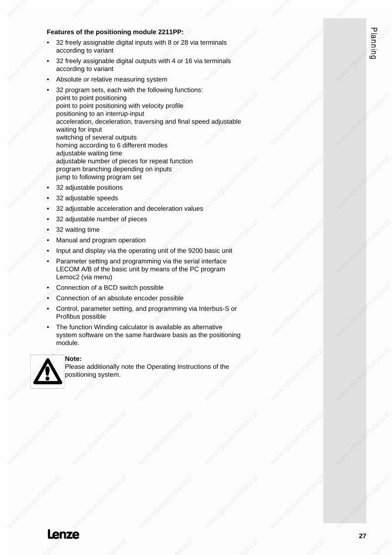
Features of the positioning module 2211PP:
• 32 freely assignable digital inputs with 8 or 28 via terminalsaccording to variant
• 32 freely assignable digital outputs with 4 or 16 via terminalsaccording to variant
• Absolute or relative measuring system
• 32 program sets, each with the following functions:point to point positioningpoint to point positioning with velocity profilepositioning to an interrup-inputacceleration, deceleration, traversing and final speed adjustablewaiting for inputswitching of several outputshoming according to 6 different modesadjustable waiting timeadjustable number of pieces for repeat functionprogram branching depending on inputsjump to following program set
• 32 adjustable positions
• 32 adjustable speeds
• 32 adjustable acceleration and deceleration values
• 32 adjustable number of pieces
• 32 waiting time
• Manual and program operation
• Input and display via the operating unit of the 9200 basic unit
• Parameter setting and programming via the serial interfaceLECOM A/B of the basic unit by means of the PC programLemoc2 (via menu)
• Connection of a BCD switch possible
• Connection of an absolute encoder possible
• Control, parameter setting, and programming via Interbus-S orProfibus possible
• The function Winding calculator is available as alternativesystem software on the same hardware basis as the positioningmodule.
Note:Please additionally note the Operating Instructions of thepositioning system.

28
5.2. Wiring with positioning control SX-1
5.2.1. Diagram 1: Mains supply

29
5.2.2. Diagram 2: Control circuit 230V
30
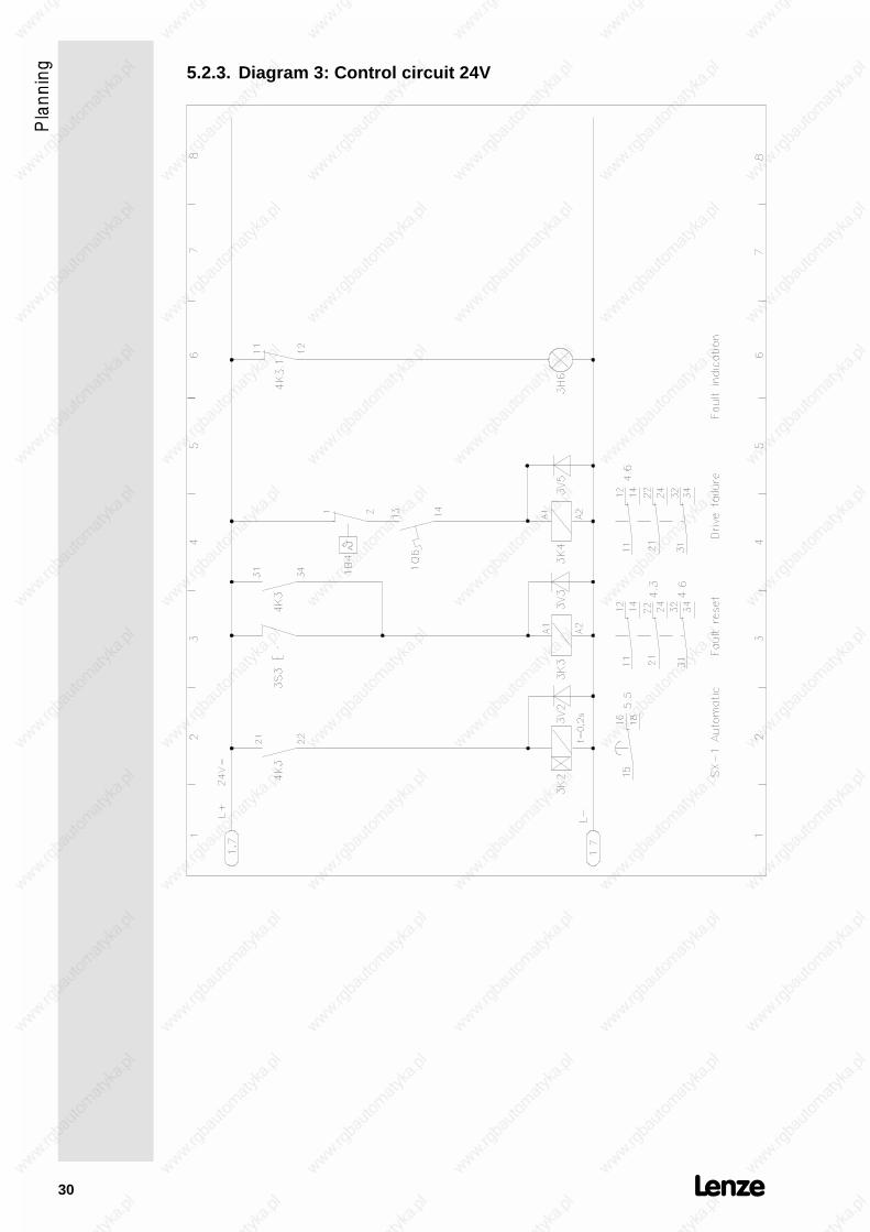
5.2.3. Diagram 3: Control circuit 24V

31
5.2.4. Diagram 4: Control connections 9200 - SX1
Ω

32
5.2.5. Diagram 5: Control connections SX1

33
6. Accessories
(All listed components must be ordered separately)
6.1. External brake resistors
R[Ω]
Pn[kW]
Order no. H[mm]
M[mm]
O[mm]
R[mm]
U[mm]
9212 29 1,1 ERBD029R01k1 120 430 510 92 64
9215 11 1,1 ERBD011R01k1 120 430 510 92 64
9217 8,5 1,1 ERBD009R01k1 120 430 510 95 64
6.2. Mains chokes
L[mH]
I[A]
Part no. a[mm]
b[mm]
c[mm]
d[mm]
e[mm]
f[mm]
k[mm]
m[mm]
n[mm]
9212 3 x 2,5 3 x 7 ELN3_0250H007 120 61 84 45 130 105 73 6.0 11
9215 3 x 1,2 3 x 25 ELN3_0120H025 150 76 140 61 180 140 95 5.0 10
9217 3 x0,75 3 x 45 ELN3_0075H045 180 91 161 74 225 165 120 6.3 11
34
6.3. RFI filter
For radio interference suppression according to EN 55011, limitvalue class A or B.
Assigned RFI filters for mains voltage of 400 V
Supply module type 9212 9215 9217
Mains current RFI filter 8 A 25 A 50 A
Order no. mains filter EZF3_008A001 EZF3_025A001 EZF3_050A004
Filter for mains voltages of up to 460 V: please contactmanufacturer
6.4. External fuses
Semiconductor protection
External fast acting fuses in the mains input protect the inputrectifier in the supply module.
Recommended semiconductor protection fuses (at mains side):
Supply module 9212 9215 9217
Mains input withrectifier protection
FF20A / 700V
14 x 51
FF63A / 700V
22 x 58
FF100A / 700V
22 x 58
Order no. EFSFF0200ARH EFSFF0630ARI EFSFF1000ARI
Input cables must be protected with standard fuses adapted to thecross-sectional area of the cables.
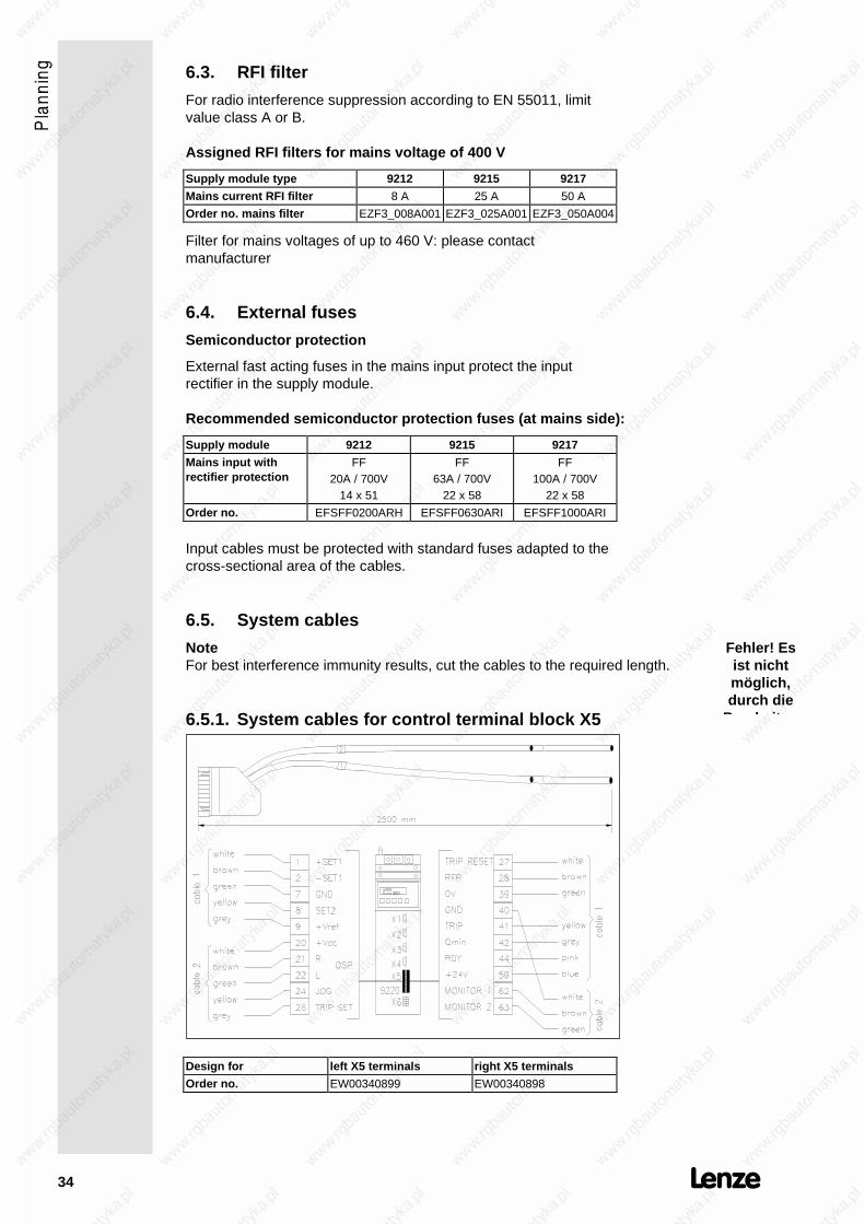
6.5. System cables
NoteFor best interference immunity results, cut the cables to the required length.
6.5.1. System cables for control terminal block X5
Design for left X5 terminals right X5 terminals
Order no. EW00340899 EW00340898
Fehler! Esist nichtmöglich,durch die
B b it

35
6.5.2. System cables for master frequency selection X2 andincremental encoder output X4
greenb lack
red
ye llow
w hite
b lack
b lack
b lack
P os ition ing contro lle r A x is m odu le A x is m odule m aster A x is m odu le s lave
Design with plugs at both ends with single plug
Order no. EW00340900 EW00340906
Note:The bridge beween pin 4 and pin 8 is necessary for theoperation with the SX1 positioning control.
Fehler! Esist nichtmöglich,durch dieB b it

36
6.5.3. System cables for resolver X3
Various lengths
+REF white- REF black
+COS red
-COS black
+SIN yellow
- SIN black
Order numbers of resolver cables
Length plugs at both ends plug at motor side plug at unit side
2.5 m - - EW00340907
5 m EWREB_______05 EW00345891 -
10 m EWREB_______10 EW00340909 -
15 m EWREB_______15 EW00345892 -
20 m EWREB_______20 EW00345893 -
25 m EWREB_______25 EW00345894 -
30 m EWREB_______30 EW00345895 -
35 m EWREB_______35 EW00345896 -
40 m EWREB_______40 EW00345897 -
45 m EWREB_______45 EW00345898 -
50 m EWREB_______50 EW00345899 -

37
6.5.4. System cables for power supply of servo motors
1
24
5
6
white
brown
black 1
black 3
black 2
0.5 m m
1.5 m m
or
2.5 m m 2
M
3
1 2 4 5 6 PE
U
V
W
X11U V W
Various lengths
blank
2
2
Order numbers of motor cables
Cable cross sectionLength 4 x 1.5 mm2
2 x 0.5 mm24 x 2.5 mm2
2 x 0.5 mm24 x 4.0 mm2
2 x 0.5 mm24 x 10 mm2
2 x 0.5 mm2
5 m EWMOL056_01505 EWMOL056_02505 EWMOL100_04005 EWMOL112_10005
10 m EWMOL056_01510 EWMOL056_02510 EWMOL100_04010 EWMOL112_10010
15 m EWMOL056_01515 EWMOL056_02515 EWMOL100_04015 EWMOL112_10015
20 m EWMOL056_01520 EWMOL056_02520 EWMOL100_04020 EWMOL112_10020
25 m EWMOL056_01525 EWMOL056_02525 EWMOL100_04025 EWMOL112_10025
30 m EWMOL056_01530 EWMOL056_02530 EWMOL100_04030 EWMOL112_10030
35 m EWMOL056_01535 EWMOL056_02535 EWMOL100_04035 EWMOL112_10035
40 m EWMOL056_01540 EWMOL056_02540 EWMOL100_04040 EWMOL112_10040
45 m EWMOL056_01545 EWMOL056_02545 EWMOL100_04045 EWMOL112_10045
50 m EWMOL056_01550 EWMOL056_02550 EWMOL100_04050 EWMOL112_10050

38
6.5.5. System calbes for supply fo fan and brake
Cable cross sectionLength 5 x 0.5 mm2
5 m EWBLL_______05
10 m EWBLL_______10
15 m EWBLL_______15
20 m EWBLL_______20
25 m EWBLL_______25
30 m EWBLL_______30
35 m EWBLL_______35
40 m EWBLL_______40
45 m EWBLL_______45
50 m EWBLL_______50
black 1
black 2
blue
brown 0.5 m m
Various length
2
X30X30
green-yellow
L1 fanN fan
Y1 + brake
Y2 - brake
PE
Servo motor
Y1+ Y2- L1 N PE
D otted line : m oto r w ith b rake bu t w ithou t fan : D S V A BS X X
Order numbers of fan and brake supply cables
39
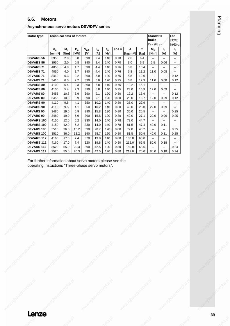
6.6. Motors
Asynchronous servo motors DSV/DFV series
Motor type Technical data of motors StandstillbrakeVn = 205 V=
Fan230V∼50/60Hz
nn Mn Pn Vn3~ In fn cos ϕ J m Mn In In[min-1] [Nm] [kW] [V] [A] [Hz] [kgcm2] [kg] [Nm] [A] [A]
DSVARS 56DSVABS 56
39503950
2.02.0
0.80.8
390390
2.42.4
140140
0.700.70
2.63.0
6.46.9
--2.5
--0.06
----
DSVARS 71DSVABS 71DFVARS 71DFVABS 71
4050405034103410
4.04.06.36.3
1.71.72.22.2
390390390390
4.44.46.06.0
140140120120
0.760.760.750.75
5.86.85.86.8
10.411.212.012.9
--11.0
--11.0
--0.08
--0.08
----
0.120.12
DSVARS 80DSVABS 80DFVARS 80DFVABS 80
4100410034553455
5.45.4
10.810.8
2.32.33.93.9
390390390390
5.85.89.19.1
140140120120
0.750.750.800.80
19.223.019.223.0
15.116.916.918.7
--12.0
--12.0
--0.09
--0.09
----
0.120.12
DSVARS 90DSVABS 90DFVARS 90DFVABS 90
4110411034803480
9.59.5
19.019.0
4.14.16.96.9
350350390390
10.210.215.815.8
140140120120
0.800.800.800.80
36.040.036.040.0
22.925.025.527.1
--22.0
--22.0
--0.09
--0.09
----
0.250.25
DSVARS 100DSVABS 100DFVARS 100DFVABS 100
4150415035103510
12.012.036.036.0
5.25.2
13.213.2
330330390390
14.014.028.728.7
140140120120
0.780.780.800.80
72.081.572.081.5
44.747.448.250.9
--40.0
--40.0
--0.11
--0.11
----
0.250.25
DSVARS 112DSVABS 112DFVARS 112DFVABS 112
4160416035203520
17.017.055.055.0
7.47.4
20.320.3
320320390390
19.819.842.542.5
140140120120
0.800.800.800.80
180.0212.0180.0212.0
60.066.563.570.0
--80.0
--80.0
--0.18
--0.18
----
0.240.24
For further information about servo motors please see theoperating Instuctions "Three-phase servo motors".

40
Parameter setting
1. LCD display
Ready (green)Curr. limit I max (red)Im pulse inhib it(ye llow )
KeysSH STPPRG
1.1. Key functions
Key Function
PRG Change between code and parameter level
Increase displayed value
+ SH Rapid increase of displayed value
Reduce displayed value
+ SH Rapid reduction of displayed value
SH + PRG Execute change. Reset after fault indication
STP Inhibit controller (see note below)
SH + STP Enable controller
Note
• For the execution command SH+PRG and the enable command SH+STP firstpress the SH key and hold, than press the PRG or STP key.
• When inhibiting the controller by pressing the STP key, it must be enabledagain by using the SH+STP command. Only then can it beenabled via terminal 28 or interface.
1.2. Plain-text display
The LCD display constists of two lines of 16 characters each. In theupper line, code no. and parameter are displayed. The arrow >shows the present level (code or parameter level), which can bechanged when pressing the or key. In the lower line, thecodes or parameters are explained.
-Arrow for code level- ↓ -Code no.- -Parameter-
> C 0 0 1 - 0 -
O p e r a t i n g m o d e-Explanatory text-
Fehler! Esist nichtmöglich,durch die
B b it

41
2. Basics of parameter setting
The drive can be adapted to your specific applications byparameter setting of the axis modules. The possible settings arearranged in the form of codes, which are numbered in ascendingorder and start with the letter "C". Each code provides severalparameters which can be selected according to the application.
Parameters can be direct values of a physical unit (e.g. 50Hz or50% related to fdmax) or numerical codes giving certain statusinformation (e.g. -0- = controller inhibited, -1- = controller enabled).In cases where the parameters represent values of physical units, itis possible to vary the increment.Example: The acceleration and deceleration can be set inincrements of 0.01 s up to 1 s and in increments of 0.1 s from 1 supwards.
For codes with more than 5 digit values, the keypad operation isdifferent: In the parameter level, the cursor can be shifted to enterlarge values. This is done by pressing SH+ and SH+ (seeexample on page 44).
In some codes, parameters can only be read but not changed.In the factory setting, only those codes are displayed which arenecessary for the most common applications. For activation of theextended code set see code table C 000.
2.1. Change parameters
Each code has a factory set parameter which can be changed.There are three different ways of selecting and confirming a newparameter, depending on the code:
Direct acceptanceThe servo axis immediately accepts the new parameter, i.e. whileyou change it using the or -key. This is possible even when thedrive is running. Parameters which are immediately accepted aremarked with ON-LINE in the code table.
Acceptance with SH + PRGThe axis accepts a new parameter when SH + PRG are pressed.This is possible even with the drive running. First press SH andthen in addition PRG. The display shows --ok-- for 0.5 seconds.The axis module now works with the new parameter. The keycombination SH and PRG can be compared to the "return" key onyour computer keyboard. If you have to set a parameter of a codein this way, the code table shows the symbol SH + PRG.

42
Acceptance with SH + PRG with controller inhibitThe axis module accepts the new parameter when it has beeninhibited prior to pressing SH + PRG. Inhibit the controller e.g. bypressing STP. First press SH and then in addition PRG. Thedisplay shows --ok-- for 0.5 seconds. The axis module works withthe new parameter when the controller is released again. If youhave to set a parameter of a code in this way, the symbol appears in the code table.
2.2. Save parameters
• When commissioning for the first time, the parameter set 1 isfactory-set. After the acceptance, new parameters are saved inthe RAM, i.e. they are saved until the controller is disconnectedfrom the mains.If you do not want to lose your setting when connecting thecontroller to the mains, save them permanently:1. Select code C003.2. Select parameter set 1 by entering -1- .3. Press SH first, and then additionally PRG. --ok-- will be
displayed.4. Now you can disconnect the servo controller from the mains.
Your settings are permanently saved under "parameter set1".
• PasswordThe input of a password prevents unauthorized changes ofparameters or code levels.
2.3. Load parameter
If you only need one parameter set, you can permanently saveyour changes under parameter set 1. After every mains connection,parameter set 1 is loaded automatically.

43
2.4. Examples
Change of the operating mode
1. enter Code C001 using or keys
-Arrow for code level- ↓ -Code no.- -parameter-
> C 0 0 1 - 0 -
O p e r a t i n g m o d e-Explanatory text-
2. change from code level to parameter level using the PRG key
-Arrow for parameter level- ↓
C 0 0 1 > - 0 -
T e r m i n a l / k e y p a d-explanatory text for the selected parameter-
3. set parameter to -1- using the key
C 0 0 1 > - 1 -
k e y p a d
4. acknowledge with the keys SH + PRG and return to code level
C 0 0 1 > - 1 -
O p e r a t i n g m o d e

44
Change of the ratio denominator.
For codes with more than 5 digit values, the keypad operation isdifferent: In the parameter level, the cursor can be shifted to enterlarge values. This is done by pressing SH+ and SH+.
1. enter code C033 using or keys
-Arrow for code level- ↓ -Code no.- -value- -exponent-
> C 0 3 3 1 . 0 0 0 E - 0 1
R a t i o d e n o m i n a t .-Explanatory text-
2. change from code level to parameter level using the PRG key
-Arrow for parameter level- ↓
C 0 3 3 >
0 . 1 0 0 0 -10-digit value- ↑
-Cursor-
3. position the cursor using the keys + SH
C 0 3 3 >
0 . 1 0 0 0
4. enter value using the key or
C 0 3 3 >
0 . 3 0 0 0
5. acknowledge with SH + PRG and return to the code level
> C 0 3 3 3 . 0 0 0 E - 0 1
R a t i o d e n o m i n a t .

45
3. Commissioning
The following notes on the commissioning do not explain allpossibilities of parameter settings. The code table at the end of thechapter lists and describes all codes in detail.
Caution!Before commissioning, check the wiring of the controller.
Typical faults are:
• incorrect screening of the cables
• earth or ground current loops
and if Lenze system cables are not used:
• incorrect connection of the motor phases
• incorrect connection of the resolver terminals
The axis modules are factory-set for terminal control and parametersetting via keypad for speed control with asynchronous motor,resolver feedback and analog set value provision at terminal 8(C005 = 11). For this standard application, the basic parametersare already programmed. Start entering the motor nameplate data(see page 47) for commissioning.
For all other applications, the basic parameters must be selected.
3.1. Basic parameter setting
Before setting the parameters of the axis module, the controllermust be inhibited, i.e. terminal 28 open, RFR ENABLE switch open,or STP key pressed.
• C000 code setAll codes in the inverter are arranged in different code sets. Withfactory setting, the standard code set is activated. It contains allcodes which are required for the most common applications.
By selecting the extended code set under code C000, thekeypad also shows those codes which are suitable for specialapplications. There is also a service code set which is notaccessible in general.
If you want to protect your parameter settings from non-authorized access you can enter a password in the form of athree-digit number. By defining a password, the parameters ofthe standard code set can only be read, but not changed whenthe password is not entered. The parameters of the extendedcode set can neither be read nor changed.
First enter the password under C094 and then set code C000 to"standard code set read only". After this, the setting of codeC000 can only be changed when the programmed password isentered.

46
• C001 Operating modeSelection between keypad control or control via LECOM-A/Binterface or parameter setting via LECOM interface. For controlor parameter setting via LECOM interface, the drive must, inaddition, be given an address in code C009 (code set -2-).
To change the operating mode, open RFR switch (X5 terminal28 open). The functions RFR ENABLE, QSP, Trip set and Tripreset are not affected and can be controlled via terminals.
After selecting the control via Lecom (C001 = 3, 5, 6, 7) thecontroller must be enabled via the selected interface. IfLecom1 control (C001 = 3) has been selected, although theinterface is not connected, the controller can be enabled againby selecting C001 = 1, and then C040 = 1. If LECOM 2 controlhas been selected (C001 = 5, 6, 7) if the interface is notconnected, the controller remains inhibited even after changingC001. To enable the controller again, select under C001 aparameter other than 5, 6, 7 save the parameter anddisconnect the controller from the mains. After reconnection,the controller can be enabled again.
• C005 ConfigurationOther control modes (e.g. torque control) or alternative methodsof producing the reference signal are available. Theconfiguration can only be changed whilst in code set -2-.Caution!When changing the configuration, control structure, motor and encoder andterminal assignment are changed.
• C025 EncoderThe set value and the actual value encoder can be selectedunder C025 (PPR). Encoder constants are set under C026.The master/slave ratio is set under C027.
• Master frequency Dig.SetThe master frequency provision is set under C025 -3- via inputDig.Set (X2); then the increments per revolution are set in codeC026. It is also possible to set the speed ratio between themaster and slave, this adjustment is made under code C027.
Under C028, a second ratio can be entered.
Under C140, the required speed ratio is activated.
Another possibility to set the angular synchronization is given bythe gearbox factor. The gearbox factor is given as a fraction.The numerator of the fraction in entered under C032, and thedenominator of the fraction is entered under C033.

47
Beispiel:
given: fDIG.SETmax = 100 kHznmax= 3000 rpm
required: encoder constant C026encoder setting C027
100 kHz = 100.000 increments/s
3000 rpm = 50rps
C 026 = 100.000 increments / s
50 / s = 2000 increments/revolution
Selectable are 512, 1024, 2048, 4096 increments/revolutionC026 = 2048 is chosen
C027 = 2048/2000 = 1,024C027 = 1,024 is to adjust.
3.2. Input of motor nameplate data
To calculate the excitation and torque generating components ofthe current vector, it is necessary to enter the motor nameplatedata correctly.
This is only possible if the controller is inhibited, i.e. RFR ENABLEopen, or the STP key pressed.
• C081 Rated motor powerThis parameter is only required for automation moduleapplications to calculate the absolute reference for the torque.The rated motor power of the Lenze servo motor, which is bestadapted to the axis module, is factory-set.
• C087 Rated motor speed
• C088 Rated motor current
For M << Mratedrequired
ratedrequired
ratedC I
M
M088 = ⋅
• C089 Rated motor frequency
• C091 cos ϕ motor

48
3.3. Setting of operating parameters
The operating parameters must be adjusted according to thespecific application requirements. Operating parameters can bemodified ON-LINE during operation. However, a preadjustment ofthe operating parameters before start-up of the motor isrecommended.• C022 Maximum current Imax
Factory set to the maximum controller current. An adjustmentof the maximum current limitation is only necessary if the maxi-mum current must be smaller than the controller peak current.
• C011 Maximum speed nmaxIn the case of analog set value provision, the maximum motorspeed determines the motor speed at maximum set value. Inthe case of digital set value provision, nmax limits the motorspeed. If nset > nmax the speed is limited to nmax. (valid for bothdirections, CW and CCW).
• C012 Acceleration time Tir, C013 deceleration time TifThe acceleration and deceleration times refer to a speedchange from 0 to nmax. The timesTir and Tif to be set can beadjusted as follows:
T = t nn - n
T = t nn - nir
ir max
1if
if max
1
⋅ ⋅2 2
When moving large inertias with short deceleration times, it ispossible that the brake energy would not be dissipated by theinternal brake resistor. The axis module trips and the fault OUE"overvoltage" or OH1 "overtemperature supply module" isdisplayed. In this case it is necessary to increase thedeceleration time or to connect an external brake resistor.
• C105 Quick stop deceleration time TQSPThe quick stop deceleration time is activated by the functionQSP quick stop.
• C039 JOG speedAn internally stored speed set value can be activated via X5terminal 24 or via C045. The JOG speed is set under C039.

49
Speed controller settingSet a low speed set value. Enable the controller release (closeRFR switch or apply a voltage of 13...30 V to X5 terminal 28). Thespeed controller can now be set. In case of uncontrolled motorrunning (oscillation etc.), the drive can be immediately stopped bypressing the STP key. After reducing the gain adjustment VpnC070, release the controller again using SH+STP.
• C070 Gain adjustment VpnIncrease Vpn until the drive becomes unstable (motor noise andLED Imax illuminated), then reduce Vpn amplification until thedrive operates smoothly. Read the Vpn value and adjust to onethird of the value.Increase the speed set value. If the motor speed does not followthe higher speed set value, but stays at 50...300 rpm, the drivemust be disconnected from the mains and after a period of 5min, the motor connections U and V must be interchanged.Switch on the mains and readjust the gain.
• C071 Integral action time of the speed controllerFactory setting optimized to the torque loop. It may benecessary to adjust higher values if the field weakening rangeis completely used or if non-adapted motors are employed. Forhigher time constants in the speed control loop (e.g. for chaindrives), it may also be necessary to readjust the integral actiontime. To change the integral action time, select the extendedcode set -2- under code C000. Increase Tn until the drive isstable. Read Tn and adjust to approx. double the value.
• C072 Amplification of the difference component of thespeed controller.This adjustment is only necessary if the time has been set to alarger time constant. The difference component of the the speedcontroller is used for compensation of the time behaviour of thetorque control circuit. The adjustment of the differencecomponent is only possible in the extended code set -2-.Change Kd until achieving optimum control behaviour.
50
4. Additional functions
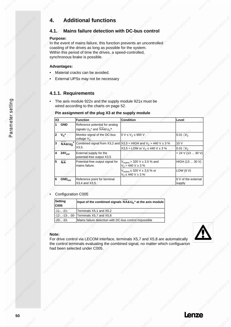
4.1. Mains failure detection with DC-bus control
Purpose:In the event of mains failure, this function prevents an uncontrolledcoasting of the drives as long as possible for the system.Within this period of time the drives, a speed-controlled,synchronous brake is possible.
Advantages:
• Material cracks can be avoided.
• External UPSs may not be necessary
4.1.1. Requirements
• The axis module 922x and the supply module 921x must bewired according to the charts on page 52.
Pin assignment of the plug X3 at the supply module
X3 Function Condition Level
1 GND Reference potential for analog
signals UG* and NA&UG*
2 VG* Monitor signal of the DC-busvoltage VZ.
0 V ≤ VZ ≤ 900 V 0.01 ⋅ VZ
3 NA&UG* Combined signal from X3,2 and
X3,5.X3,5 = HIGH and VZ > 440 V ± 3 %
X3,5 = LOW or VZ ≤ 440 V ± 3 %
10 V
0.01 ⋅ VZ
4 24Vext External supply for thepotential-free output X3,5
+ 24 V (13 ... 30 V)
5 NA Potential-free output signal formains failure.
Vmains > 320 V ± 3.5 % andVZ > 440 V ± 3 %
Vmains ≤ 320 V ± 3,5 % orVZ ≤ 440 V ± 3 %
HIGH (13 ... 30 V)
LOW (0 V)
6 GNDext Reference point for terminalX3,4 and X3,5.
0 V of the externalsupply
• Configuration C005
SettingC005
Input of the combined signals NA&UG* at the axis module
-11-, -21- Terminals X5,1 and X5,2
-12-, -13-, -30- Terminals X5,7 and X5,8
-20-, -33- Mains failure detection with DC-bus control impossible
Note:For drive control via LECOM interface, terminals X5,7 and X5,8 are automaticallythe control terminals evaluating the combined signal, no matter which configuarionhad been selected under C005.

51
• Parameter setting of the mains failure detection:The following codes affect the drive properties in case of mainsfailure:
C079 Proportional gain of the DC-bus voltage controller (Vz-controller) (seesignal flow chart p.55)
C080 Integral-action component of the Vz-controller
C228 Acceleration integrator for the set value of the DC-bus voltage
C229 Activation of mains failure detectionC229 = -1- : Mains failure detection activated
C236 Vsetl (Vz-controller).Ater the detection of a mains fialure and the activation of the DC-buscontrol, the value of C237 is the set value of the Vz-controller
C237 This code indirectly determines the possible speed decrease during acontroller cycle.
• In drive configuration with several controllers and DC-busconnection (one master drive and one or several slavedrives), the mains failure detection with DC-bus control mayonly be activated for the master drive.

52
4.1.1. WiringNote• For radio interference suppression, all relays have to be equipped with free-
wheeling diodes!• all relays: Ri < 1KΩ
a) Wiring for C005 = 11 und 21
b) Wiring for C005 = 12, 13, 30 and for interface control

53
4.1.2. SettingThese setting instructions are meant as guideline and must notalways decelerate the machine to standstill before reaching theundervoltage threshold. The parameter setting of the codes, whichinfluences the DC-bus control during mains failure detection (C079,C080, C228, C236, C237), depend on the size of the driveconfigurations and the mechanical features of the system.There are minimum speeds at which the energy of the mechanicalsystem is not high enough to compensate the losses which occurduring the controlled deceleration (switched-mode power supplies,inverter, machines).
Aim:
• The aim is to have a controlled speed deceleration that allows aDC-bus voltage value which remains higher than theundervoltage threshold for as long as possible.As soon as the value falls below this threshold, pulse inhibit willbe set and the drive will coast to standstill.
• The brake chopper should not be activated during the controlleddeceleration of the speed.Therefore, the parameter setting of the DC-bus control shouldbe "softly". It is not very important whether the DC-bus can beloaded to the voltage set under C236.
Required measuring units:
• Oscilloscope,at least 2 channels, if possible with memory.
Test set-up:
• Connect channel 1 of the oscilloscope with X5,62 of the axismodule (speed monitor).
• Connect channel 2 of the oscilloscope with X3,2 of the supplymodule (DC-bus monitor).
• If available, connect channel 3 of the oscilloscope with X5,44 ofthe axis module (RDY-output).
Presettings:
1. Set the speed controller of the axis module drive configurationas usual.
2. Activate the mains failure detection of the master drive (C229 =-1-).If the function is activated, the RDY-output changes from theHIGH level to the LOW level. As soon as the speed isdecelerated to 0, the RDY-output re-changes to HIGH.
3. The relevant codes must be set as follows:
Code Presetting
C079 -1-
C080 150 s
C228 1/10...1/20 of the natural slow-down time of the machine atmaximum operating speed
C229 -1-
C236 680 V
C237 1000 rpm or more

54
Setting course:1. Select a medium speed as set value according to the occuring
speed range of the system.2. Switch-off the mains.
The oscillogramme shows the reaching of the undervoltagethreshold on channel 2, the DC-bus voltage decreases slowly(see fig. 1)
UG*
c
C236
V m in
t 1
V B r
t1 = Start of the DC-bus control
c = Undervoltage thresholdreached
fig. 1: Start of the settingDC-bus voltage during DC-bus control
3. Increase C079 to reach the undervoltage threshold at a speedas low as possible. For very small final speed values, you mayreduce C228.
4. Repeat steps 1.) to 3.) at maximum and minimum systemspeed.
5. Reduce C080 at maximum system speed until the DC-busvoltage does no longer overshoot the brake-chopper threshold(see fig. 2).You may also reduce C237 to limit the speed decrease duringdeceleration.
UG*
c
C236
V m in
t 1
V B r
t1 = Start of DC-bus control
c = Undervoltage thresholdreached
fig. 2: Real settingDC-bus voltage during DC-bus control
6. The increase of the Vz acceleration integrator C228 prolongs thedeceleration period.
7. Save the setting under C003.

55
Signal fow chart DC-bus control

56
4.2. Homing mode
• C250 Homing modeIn the homing mode (C250 = -0-) the increments of the masterfrequency at the DIG.SET input are processed as a relativechange of angle. By activating the homing mode (C250 = -1-) itis possible to refer to an absolute angle position of the motorshaft. The homing mode can only be activated if the controller isinhibitied. It is initiated by means of JOG function.Functional sequence:Start the homing mode by means of the JOG function enable.The RDY signal indicates "not ready". The drive runs at theselected JOG speed. After blocking the JOG signal (e.g. bymeans of a proximity switch), the drive continues to run to thehome position and stops. The RDY signal indicates "ready".
If controller inhibit or QSP are activated during homing, the RDYsignal remains "not ready" until the homing process is finished.
0
360o
o
Input signal JOG
0
JOG speed
Home position
any position
t
Motor speed
Motor shaftposition
Output signal RDY
• C252 Angle offsetThe shift range of the home position is one revolution of themotor shaft. 360° is resolved into 2048 steps. The adjustmentcan be made ON-LINE when the motor is running. The zeropulse of the encoder emulation X4 is also resolved in 256 steps.
• C254 Amplification of the angle controllerThe angular controller is active when using a master frequencyDIG.SET input or if the homing mode is active. By selectingVpw=0, the angular controller is deactivated. In this case, themaster frequeny is processed as speed set value and not as setangle increments. Before adjusting the amplification of theangular controller, the speed controller must be optimized.
• C159 Homing OKC159 displays whether the homing was successful or not:C159 = -1- homing successfully completedC159 = -0- homing not completedC159 may also be used for simulating a homing mode:Set C159 = -1- and manually activate the angle offset underC252.
57
4.3. Further additional functions
• C004 Switch-on displayEntering a code number under C004 determines whichparameter is to be displayed after switching-on.
• C018 Chopper frequencyThe chopper frequency determines the noise level. The chopperfrequency can either be 8 or 16 kHz. Changing the chopperfrequency changes the admissible permanent load of the axismodule.
• C255 Following error limitIf an following error exceeds the value entered under C255during master frequency operation (C005 = -13- or -21-) and anamplification of the angle controller of C254 > 0, an internalsignal will be generated for the error status >>Following errorlimit exceeded<< . If this signal is applied to the terminal Qmin(X5,42) via C117, the Qmin terminal will change its level fromHIGH to LOW as soon as the set limit value is exceeded.
For following errors of more than 3188 increments, also theRDY message will be set to LOW and >>following error<< willbe displayed.(see page 74)

58
5. Serial interfaces
The 9200 servo axis modules can communicate via the serialinterfaces LECOM1 and LECOM2 with superimposed hosts (PLCor PC) as well as Lenze operating units.
The LECOM1 interface (connector X1) is used to process theLECOM A/B protocol. The LECOM1 interface can also be used toconnect devices to the RS 232C standard (LECOM-A) or to the RS485 standard (LECOM-B). The interface is suitable for parametersetting, monitoring, diagnosis and process control.
For more demanding applications, a field bus connecting modulecan be used. For the parameter setting, this interface is generallycalled LECOM2.The following bus systems are available:
• Interbus-S interface module 2110
• Profibus interface module 2130
5.1. LECOM1 interface X1
The standard serial interface X1 fulfills the standard RS 232 C aswell as the standard RS 485.
Using the common RS 232 C interface, simple point-to-pointconnection with a maximum cable length of 15 m can be achieved.Almost every personal computer (PC) or other master system isequiped with this interface. For several drives and larger distances,the RS 485 interface must be used. Only two wires are used toenable the communication of up to 31 controllers via a maximumdistance 1200 m.
The LECOM A/B protocol is based on the 1745 ISO standard andsupports up to 90 controllers. It recognizes faults and thereforeavoids the transmission of faulty data.
Pin assignment X1:
Pin Name Input/Output Explanation
1 +VCC15 Output Supply voltage +15V/50mA
2 RxD Input Data receiving line RS232C
3 TxD Output Data transmitting line RS232C
4 DTR Output Transmission control RS232C
5 GND -- Controller reference potential RS232C
6 DSR Input (unused)
7 T/R (A) Output/Input RS485
8 T/R (B) Output/Input RS485
9 +VCC5 Output Supply voltage +5V
Baud rate: 1200/2400/4800/9600 Bd (to be changed via C125).
Protocol: LECOM-A/B V2.0

59
5.2. LECOM status messages
• C068 Operating state
Bit no. Signal
0, 1, 2, 3 Operating fault
4, 5, 6, 7 Communication fault
8 RFR enable
9 Qmin10 running
11 IMP
12 QSP
13 Imax14 Nact = Nset
• C069 Controller state
Bit no. Signal
0 BALARM
1 CALARM
2 PCHG
3 REMOT
4 AUTO
5 RESET
6 XXX
7 RFR
15 TRIP
• C067 Fault numbers of the operating faults (see "Service")
--- OC1 OC2 OC5 OUE OH1 OH2 U15 CCr Pr Sd2 EEr UEr
0 11 12 15 22 51 52 70 71 72 82 91 92
Further information on the serial communication LECOM1(LECOM-A/B) can be obtained from the Operating InstructionsLECOM-A/B.
For extensions, the following modules are available:
• 2101 Interface with mains isolation for RS422/RS485
• 2122/2123 Interface for optical fibres (LECOM-LI)
60
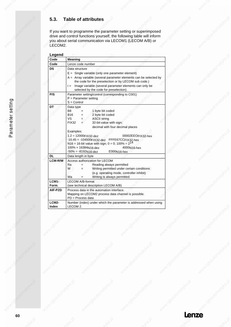
5.3. Table of attributes
If you want to programme the parameter setting or superimposeddrive and control functions yourself, the following table will informyou about serial communication via LECOM1 (LECOM A/B) orLECOM2.
LegendCode Meaning
Code Lenze code number
DS Data structureE = Single variable (only one parameter element)A = Array variable (several parameter elements can be selected by
the code for the preselection or by LECOM sub code.)I = Image variable (several parameter elements can only be
selected by the code for preselection).
P/S Parameter setting/control (corresponding to C001)P = Parameter settingS = Control
DT Data typeB8 = 1 byte bit codedB16 = 2 byte bit codedVS = ASCII stringFIX32 = 32-bit-value with sign;
decimal with four decimal placesExamples:1.2 = 12000FIX32-dez 00002EEOFIX32-hex-10.45 = -104500FIX32-dez FFFE67CCFIX32-hexN16 = 16-bit value with sign; 0 = 0; 100% = 214
100% = 16384N16-dez 4000N16-hex-50% = -8192N16-dez E000N16-hex
DL Data length in byte
LCM-R/W Access authorization for LECOMRa = Reading always permittedW = Writing permitted under certain conditions
(e.g. operating mode, controller inhibit)Wa = Writing is always permitted
LCM1-Form.
LECOM A/B-format(see technical description LECOM A/B)
AIF-PZD Process data in the automation interface.Mapping on LECOM2 process data channel is possible.PD = Process data
LCM2-Index
Number (index) under which the parameter is addressed when usingLECOM 2.

61
Code P/S DS DT DE D/L LCM-R/W LCMForm.
AIF-PZD LCM2Index
C000 P E FIX32 1 4 Ra VD -- 24575
C001 P E FIX32 1 4 Ra/Wa VD -- 24574
C002 P E FIX32 1 4 Ra/W VD -- 24573
C003 P E FIX32 1 4 Ra/W VD -- 24572
C004 P E FIX32 1 4 -- VD -- 24571
C005 P E FIX32 1 4 Ra/W VD -- 24570
C009 P E FIX32 1 4 -- VD -- 24566
C011 P E FIX32 1 4 Ra/W VD -- 24564
C012 P E FIX32 1 4 Ra/W VD -- 24563
C013 P E FIX32 1 4 Ra/W VD -- 24562
C017 P E FIX32 1 4 Ra/W VD -- 24558
C018 P E FIX32 1 4 Ra/W VD -- 24557
C022 P E FIX32 1 4 Ra/W VD -- 24553
C025 P E FIX32 1 4 Ra/W VD -- 24550
C026 P I FIX32 1 4 Ra/W VD -- 24549
C027 P I FIX32 1 4 Ra/W VD -- 24548
C028 P I FIX32 1 4 Ra/W VD -- 24547
C030 P E FIX32 1 4 Ra/W VD -- 24545
C031 P E FIX32 1 4 Ra/W VD -- 24544
C032 P E FIX32 1 4 Ra/W VD -- 24543
C033 P E FIX32 1 4 Ra/W VD -- 24542
C039 P E FIX32 1 4 Ra/W VD -- 24536
C040 P E FIX32 1 4 Ra/W VD -- 24535
C041 S E FIX32 1 4 Ra/W VD -- 24534
C042 S E FIX32 1 4 Ra/W VD -- 24533
C043 P E FIX32 1 4 Ra/W VD -- 24532
C045 S E FIX32 1 4 Ra/W VD -- 24530
C046 S E FIX32 1 4 Ra/W VD -- 24529
C047 S E FIX32 1 4 Ra/W VD -- 24528
C050 S E FIX32 1 4 Ra VD -- 24525
C051 S E FIX32 1 4 Ra VD -- 24524
C054 S E FIX32 1 4 Ra VD -- 24521
C056 S E FIX32 1 4 Ra VD -- 24519
C059 P E FIX32 1 4 Ra VD -- 24516
C060 S E FIX32 1 4 Ra VD -- 24515
C061 S E FIX32 1 4 Ra VD -- 24514
C067 P E FIX32 1 4 Ra VD -- 24508
C068 S E B16 1 2 Ra VH -- 24507
C069 S E B8 1 1 Ra VH -- 24506
C070 P E FIX32 1 4 Ra/W VD -- 24505
C071 P E FIX32 1 4 Ra/W VD -- 24504
C072 P E FIX32 1 4 Ra/W VD -- 24503
C079 P E FIX32 1 4 Ra/W VD -- 24496
C080 P E FIX32 1 4 Ra/W VD -- 24495
C081 P E FIX32 1 4 Ra/W VD -- 24494
C087 P E FIX32 1 4 Ra/W VD -- 24488
C088 P E FIX32 1 4 Ra/W VD -- 24487
C089 P E FIX32 1 4 Ra/W VD -- 24486
C091 P E FIX32 1 4 Ra/W VD -- 24484
C093 S E FIX32 1 4 Ra VD -- 24482
C094 P E FIX32 1 4 Ra/W VD -- 24481
C098 P E FIX32 1 4 Ra/W VD -- 24477
C099 P E VS 1 6 Ra VS -- 24476
C105 P E FIX32 1 4 Ra/W VD -- 24470
C117 P E FIX32 1 4 Ra/W VD -- 24458
C125 P E FIX32 1 4 Ra/W VD -- 24450

62
Code P/S DS DT DE D/L LCM-R/W LCMForm.
AIF-PZD LCM2Index
C140 P E FIX32 1 4 Ra/W VD -- 24435
C153 P E FIX32 1 4 Ra/W VD -- 24422
C154 P E FIX32 1 4 Ra/W VD -- 24421
C158 S E FIX32 1 4 Ra VD -- 24417
C159 P E FIX32 1 4 Ra/W VD -- 24416
C161 P E FIX32 1 4 Ra VD -- 24414
C162 P E FIX32 1 4 Ra VD -- 24413
C163 P E FIX32 1 4 Ra VD -- 24412
C164 P E FIX32 1 4 Ra VD -- 24411
C165 P E FIX32 1 4 Ra VD -- 24410
C166 P E FIX32 1 4 Ra VD -- 24409
C167 P E FIX32 1 4 Ra VD -- 24408
C168 P E FIX32 1 4 Ra VD -- 24407
C180 P E FIX32 1 4 Ra/W VD -- 24395
C183 P E FIX32 1 4 Ra/W VD -- 24392
C184 P E FIX32 1 4 Ra/W VD -- 24391
C185 P E FIX32 1 4 Ra/W VD -- 24390
C186 P E FIX32 1 4 Ra/W VD -- 24389
C187 P E FIX32 1 4 Ra/W VD -- 24388
C200 P E VS 1 14 Ra VS -- 24375
C205 P E OS 1 0 Ra VO -- 24370
C228 P E FIX32 1 4 Ra/W VD -- 24347
C229 P E FIX32 1 4 Ra/W VD -- 24346
C236 P E FIX32 1 4 Ra/W VD -- 24339
C237 P E FIX32 1 4 Ra/W VD -- 24338
C249 P E FIX32 1 4 Ra/W VD -- 24326
C250 P E FIX32 1 4 Ra/W VD -- 24325
C252 P E FIX32 1 4 Ra/W VD -- 24323
C253 P E FIX32 1 4 Ra/W VD -- 24322
C254 P E FIX32 1 4 Ra/W VD -- 24321
C255 P E FIX32 1 4 Ra/W VD -- 24320
C300 S E FIX32 1 4 Ra VD -- 24275
C350 P E FIX32 1 4 Ra VD -- 24225
C351 P E FIX32 1 4 Ra VD -- 24224
C352 P E FIX32 1 4 Ra/W VD -- 24223
C353 P A FIX32 8 4 Ra VD -- 24222
C354 P A FIX32 8 4 Ra VD -- 24221
C355 P A FIX32 8 4 Ra VD -- 24220
C356 P A FIX32 8 4 Ra VD -- 24219
C357 P E FIX32 1 4 Ra/W VD -- 24218
C358 P A FIX32 3 4 Ra VD -- 24217
C359 P E FIX32 1 4 Ra VD -- 24216
C370 P E FIX32 1 4 Ra/W VD -- 24205
C380 S E I16 1 2 Ra/W VH PZD 24195
C381 S E I16 1 2 Ra VH PZD 24194
C382 S E I16 1 2 Ra VH PZD 24193
C387 S E I16 1 2 Ra VH PZD 24188
C388 S E I16 1 2 Ra/W VH PZD 24187
C391 S E U16 1 2 Ra VH PZD 24184
C400 P E FIX32 1 4 -- VD -- 24175
C401 P E FIX32 1 4 -- VD -- 24174
C402 P E FIX32 1 4 -- VD -- 24173
C403 P E FIX32 1 4 -- VD -- 24172
C404 P E FIX32 1 4 -- VD -- 24171
C405 P E FIX32 1 4 -- VD -- 24170

63
6. Code table
The following table shows which settings can be performed withwhich codes. Detailed explanation about the codes and thefunctions which can be achieved, are described in special chapters.For the acceptance of parameters see page 41.
How to read the code table:
Column Short form MeaningCode C000
C017*C043 (L)
Code digit of the standard code setCode digit of the extended code setCode digit can only be reached via the LECOM interface; codeis not displayed
Parameter -0- The factory setting is printed in bold.Acceptance ON-LINE
SH + PRGUnit immediately accepts new parameterUnit accepts new parameter after pressing SH+PRGUnit accepts parameter only if the controller is inhibited whenpressing SH+PRG.
Code Name Parameter Accept-ance
seepage
C000 Code set -0--1--2--9-
-11-
-P-xxx
Standard code set read onlyStandard code setExtended code setService code set (service passwordneccessary)Code set forautomation modulePassword requestEnter password
SH+PRGpassword
SH+PRG
45
C001 Operatingmode -0-
-1--2--3--4--5--6--7-
Control: Parameter setting:Terminals KeypadKeypad KeypadTerminals LECOM1LECOM1 LECOM1Terminals LECOM2LECOM2 LECOM2LECOM2 KeypadLECOM2 LECOM1
45
C002 Load parameterset
-0- Factory setting
C003 Storeparameter set
-1- Parameter set 1 SH+PRG
C004 Switch-ondisplay
51 Code no. for parameter displayedafter first switch-on
SH+PRG 57
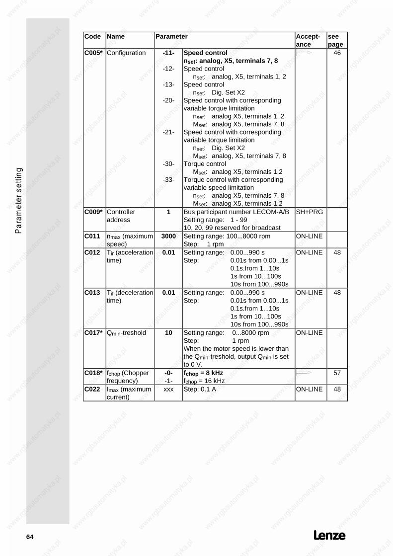
64
Code Name Parameter Accept-ance
seepage
C005* Configuration -11-
-12-
-13-
-20-
-21-
-30-
-33-
Speed controlnset: analog, X5, terminals 7, 8Speed control
nset: analog, X5, terminals 1, 2Speed control
nset: Dig. Set X2Speed control with correspondingvariable torque limitation
nset: analog X5, terminals 1, 2Mset: analog X5, terminals 7, 8
Speed control with correspondingvariable torque limitation
nset: Dig. Set X2Mset: analog, X5, terminals 7, 8
Torque controlMset: analog X5, terminals 1,2
Torque control with correspondingvariable speed limitation
nset: analog X5, terminals 7, 8Mset: analog X5, terminals 1,2
46
C009* Controlleraddress
1 Bus participant number LECOM-A/BSetting range: 1 - 9910, 20, 99 reserved for broadcast
SH+PRG
C011 nmax (maximumspeed)
3000 Setting range: 100...8000 rpmStep: 1 rpm
ON-LINE
C012 Tir (accelerationtime)
0.01 Setting range: 0.00...990 sStep: 0.01s from 0.00...1s
0.1s.from 1...10s1s from 10...100s10s from 100...990s
ON-LINE 48
C013 Tif (decelerationtime)
0.01 Setting range: 0.00...990 sStep: 0.01s from 0.00...1s
0.1s.from 1...10s1s from 10...100s10s from 100...990s
ON-LINE 48
C017* Qmin-treshold 10 Setting range: 0...8000 rpmStep: 1 rpmWhen the motor speed is lower thanthe Qmin-treshold, output Qmin is setto 0 V.
ON-LINE
C018* fchop (Chopperfrequency)
-0--1-
fchop = 8 kHzfchop = 16 kHz
57
C022 Imax (maximumcurrent)
xxx Step: 0.1 A ON-LINE 48

65
Code Name Parameter Accept-ance
seepage
C025* Encoder -0--1--3--5--13-
noe encoder selected for settingbipolar set value X5, terminals 1, 2Dig. Set master frequency X2unipolar set value X5, terminals 7, 8act. resolver value X3
SH+PRG 46
C026* Encoderconstant
-0--1--2--3--4-
no encoder constant512 increments/revolution1024 increments/revolution2048 increments/revolution4096 increments/revolution
SH+PRG 46
C027* Encoder setting -0-1.000
no setting requiredSetting range: -5...0...+5 LECOM: -5000...0...+5000Step: 0.001Adjustable speed ratio between slaveand master drive nset/nmaster whenusing the Dig. Set input.
ON-LINE 46
C028* Encoder setting2
-0-1.000
no setting requiredSetting range: -5...0...+5 LECOM: -5000...0...+5000Step: 0.001Second adjustable speed ratio for theDig. Set input. The controller isenabled (changing the parameterform C027 to C028) via code C 140.
ON-LINE 46
C030* Encodersimulation
-1--2--3--4-
256 increments/revolution512 increments/revolution1024 increments/revolution2048 increments/revolution
SH+PRG
C031* noffset 0 Setting range: -1000...+1000Step: 10 mVOffset adjustment of the selectedanalog speed set value input
ON-LINE
C032* Rationumerator
0.1 Setting range: -3.2767...+3.2767Step: 0.0001Numerator of the gearbox factor forthe Dig. Set input. The total ratio canbe obtained from the follow. formula:
V =C027 C032
C033 or V =
C028 C032C033
⋅ ⋅
Due to an internal limitation, onlyvalues from V= -5.000...+5.000 canbe realized.
ON-LINE 46
C033* Ratiodenominator
0.1 Setting range: +0.0001...+3.2767Step: 0.0001Denominator of the gearbox factor forthe Dig.Set input (formula: see C032)
ON-LINE 46
C039 JOG speed 20 Setting range: -nmax...+nmaxStep: 1 rpm
ON-LINE
C040 RFR (controllerenable)
-0--1-
Controller inhibitedController enabled
SH+PRG

66
Code Name Parameter Accept-ance
seepage
C041 CW/CCW -0--1-
Set value not invertedSet value inverted
SH+PRG
C042 QSP (Quickstop)
-0--1-
Quick stop inactiveQick stop active (The speed set valuegoes to digital 0 with the quick stopdeceleration time under C105)
SH+PRG
C043(L)
Trip Reset -0--1-
no act. fault/ reset faultactual fault
ON-LINE
C045 JOG enable -0--1-
JOG set value inhibitedJOG set value enabled
SH+PRG
C046 nset 1(speed setvalue 1)
xxxx Setting range: -nmax...+nmaxStep: 1 rpmDisplay of the externally adjustedspeed set value. For keypad andLECOM control: on-line set valueselection
ON-LINE
C047 Mmax(torque limit)
xxx Setting range: 0...100.0% or-100.0...+100.0% for torque controlStep: 0.1%The maximum torque which can beobtained, depends on the type ofservo motor and the axis moduleemployed
ON-LINE
C050 nset 2 (speedset value 2)
_xxxx Setting range: -nmax...+nmaxStep: 1 rpmEffective speed set value at speedcontroller input
read only
C051 nact (motorshaft speed)
_xxxx Setting range: -9765...9765 rpmStep: 1 rpm
read only
C054 Imot(motor current)
xxx Setting range: 0.0...maximum current
Step: 0.1 AThe displayed value is calculatedfrom the sinus oscillations of thecurrent. the difference to the actualeffective motor current is approx.10%. In the field weakening range, alarger difference may be possible.
read only
C056 Mset(effectivetorque setvalue)
xxx Setting range: -100.0...+100.0%Step: 0.1%The maximum torque which can beobtained (100%) depends on the typeof servo motor and the axis moduleemployed
read only
C059* Pole pairnumber
xx read only
C060* Rotor position xxxx Setting range: 0...2047 incrementsStep: 1 increment
read only

67
Code Name Parameter Accept-ance
seepage
C061 Utilization I x t xxxx Setting range: 0.0...+100.0%Step: 0.1%The indicated value is determined bythe current-time integral I x t of thecontroller current. When reaching100% the I x t monitoring setsoverload trip
read only
C067 Fault diagnosis xxx see under "Service" 74C068(L)
Operating state see under "Service" read only 59
C069(L)
Controller state see under "Service" read only 59
C070 Vpn (gain ofspeedcontroller)
30 Setting range: 0...500Step: 1
ON-LINE 49
C071* Tn(Integral actiontime of speedcontroller)
10
9999
Setting range: 2.5...100 msStep: 0.5 msDeactivate integral component
ON-LINE 49
C072* kd(differentialamplification ofspeedcontroller)
0 Setting range: 0...5Step: 0.1
ON-LINE 49
C079* Vp(Vz-controller)
1000 Setting range: 0...9000Step: 1
ON-LINE 53
C080* Tn(Vz-controller)
1.0 s Setting range: 0.01...150 ON-LINE 53
C081* Rated motorpower
xxx.x Setting range: 0.1...650 kWStep: 0.1 kW
47
C087 Rated motorspeed
xxxx Setting range: 300...6000 rpmStep: 1 rpm
C088 Rated motorcurrent
xxx Setting range: 0.1A...max. controllercurrentStep: 0.01 A
C089 Rated motorfrequency
xxx.x Setting range: 10.0...300.0 HzStep: 0.1 Hz
C091 cos ϕ Motor x.xx Setting range: 0.50...0.99Step: 0.01
C093* Controlleridentification
xx read only
C094* Pass word 0 enter any password (0...999)no password defined
SH+PRG 42
C098 Language -0--1--2-
GermanEnglishFrenchNote:The setting will not be overwrittenwhen loading the factory setting!
C099* Softwareversion
92_5.x Number to identify the softwareversion
read only
C105 Quick stopdecelerationtime TQSP
0.01 Setting range: 0.00...990 sStep: 0.01 s from 0.00...1 s
0.1 s from 1...10 s1 s from 10...100 s10 s from 100...990 s
ON-LINE 48
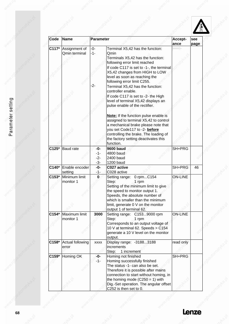
68
Code Name Parameter Accept-ance
seepage
C117* Assignment ofQmin terminal
-0--1-
-2-
Terminal X5,42 has the function:QminTerminals X5,42 has the function:following error limit reachedIf code C117 is set to -1-, the terminalX5,42 changes from HIGH to LOWlevel as soon as reaching thefollowing error limit C255.Terminal X5,42 has the function:controller enable.If code C117 is set to -2- the Highlevel of terminal X5,42 displays anpulse enable of the rectifier.
Note: If the function pulse enable isassigned to terminal X5,42 to controla mechanical brake please note thatyou set Code117 to -2- beforecontrolling the brake. The loading ofthe factory setting deactivates thisfunction.
C125* Baud rate -0--1--2--3-
9600 baud4800 baud2400 baud1200 baud
SH+PRG
C140* Enable encodersetting
-0--1-
C027 activeC028 active
SH+PRG 46
C153* Minimum limitmonitor 1
0 Setting range: 0 rpm...C154Step: 1 rpmSetting of the minimum limit to givethe speed to monitor output 1.Speeds, the absolute number ofwhich is smaller than the minimumlimit, generate 0 V on the monitoroutput 1 of terminal 62.
ON-LINE
C154* Maximum limitmonitor 1
3000 Setting range: C153...9000 rpmStep: 1 rpmCorresponds to an output voltage of10 V at terminal 62. Speeds > C154generate a 10 V level on the monitoroutput.
ON-LINE
C158* Actual followingerror
xxxx Display range: -3188...3188incrementsStep: 1 increment
read only
C159* Homing OK -0--1-
Homing not finishedHoming successfully finishedThe status -1- can also be set.Therefore it is possible after mainsconnection to start without homing, inthe homing mode (C250 = 1) withDig.-Set operation. The angular offsetC252 is then set to 0.
SH+PRG
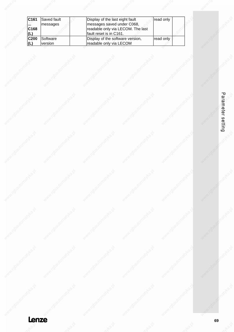
69
C161...C168(L)
Saved faultmessages
Display of the last eight faultmessages saved under C068,readable only via LECOM. The lastfault reset is in C161.
read only
C200(L)
Softwareversion
Display of the software version,readable only via LECOM
read only

70
Code Name Parameter Accept-ance
seepage
C228* Accelerationtime (Vz-controller)
0.01 Setting range: 0.00...990 sStep: 0.01 s from 0.00...1 s
0.1 s from 1...10 s1 s from 10...100 s10 s from 100...990
ON-LINE 53
C229* ActivationVz-controller
-0-
-1-
Mains failure detection with Vz-controlnot activatedMains failure detection with Vz-controlactivated
53
C236* Vset(Vz-controller)
600 Setting range: 300...900 VStep: 1 V
ON-LINE 53
C237* Influence ofVz-control
1000 Setting range: 1...8000 rpmStep: 1 rpm
ON-LINE 53
C249(L)
LECOM1-codebank
-0--1--2--3--4--5--6--7-
C000 to C255C250 to C505C500 to C755C750 to C1005C1000 to C1255C1250 to C1505C1500 to C1755C1750 to C2000
SH+PRG
C250* Homing mode -0--1-
not activeactive
56
C252* Angle offset 0 Setting range: 0...2047Step: 1
ON-LINE 56
C253* Speed-proportionalangle offset
8.5 Setting range: -819.1...+819.1 incre-ments (at 4000 rpm)
Step: 1Possibility to correct an angularoffset, which is proportional to thespeed and depending on the cycletime. The setting refers to anincremental deviation of 4000 rpm.
ON-LINE
C254* Vpw 14 Setting range: 0...16Step: 1
ON-LINE 56
C255* Following errorlimit
10 Setting range: 10...3071 incrementsStep: 1 increment
ON-LINE 57

71
Code Name Parameter Accept-ance
seepage
C370* Automationinterface
-0-
-1-
Automation interface activeAutomation interface inactiveThe automation communication mustbe activated when using an auto-mation module or a field bus connec-tion LECOM2. If the communication isenabled, without communicating tothe other side, the controller remainsinhibited. The communication via theautomation interface can be activatedindependently of the operatíng modeC001 when the controller is inhibited(C040 = 0).Caution!To ensure a faultless initialization, theLECOM interface may only beaccessed after one sec.Note:The setting will not be overwrittenwhen loading factory setting!
C380(L)
RP-set speed(corresponds toC046)
_xxxxx Display range: -26844...+26844(8000 rpm = 26844)
Step: 1
ON-LINE
C381(L)
RP-nset2(corresponds toC050)
_xxxxx Display range: -26844...+26844(8000 rpm = 26844)
Step: 1
read only
C382(L)
RP-actualspeed(corresponds toC051)
_xxxxx Display range: -32767...+32767(9765 rpm = 32767)
Step: 1Note:Quick display without time message!
read only
C387(L)
RP-set torque(corresponds toC056)
_xxxxx Display range: -32767...+32767(100% = 32767)
Step: 1
read only
C388(L)
RP-Mlimit(corresponds toC047)
_xxxxx Display range: -32767...+32767Step: 1
ON-LINE
C391(L)
RP-act. angle(corresponds toC060)
xxxxx Display range: 0...65535(360° = 16384)
Step: 1
read only

72
7.S
ign
al flow
chart axis m
od
ules
D iffe ren tia l am p lifie rC011
C046
C039
C045
C026
C027
C041
C012 C013
C105C042
C070 C071 C072
C051
+ SET1
-SE T1
SET 2
un ip o la r
o ffse t m ax
C031
L im it C W / C CW
CW /CC W
Q S P
Q SP Q SPT
JO G va lue
C onsta n t
Se ttin g
DIG .SET
An g le co n tro lle r
Ho m e position sh ift
An g lese tC250
C252
V
C050
M onito r1
10 b it
10 b it
E ncode rs im u la tion
X4
42
62
C017
n th resho ld8 b it v pn T n k d
C060
X2f
1
2
24 21 22
JO G -en ab le
f
Speed control
M m a x
C047lim it
RX3RD
n act
nQ m in
+
+
+
+
+
C254
T a rge t w in dow
w
d wd t
ww
pw
dwdt
C056
Re so lve r eva lua tio n
C005
C onfig u ra tion
F actory se tting
n-con tro lle r
Ho m ing m o de
Se t va luein te g ra to r
Set value conditioning
8
7
C028
C140
Settin g
C030
C032C033
AD
AD n 1se t
T ir T if
± 1
AD
C154
C153
a ctn
An g le act
M se t
11 ,1 2 ,2 0 ,3 3
12 ,20
11 ,33
30
13 ,21
n n
1 1 ,1 2 ,2 0 ,21
3 0 ,33
20 ,213 0 ,3 3
1 1 ,1 2 ,1 3
C380
C388
S et value influence,w hen us ing m odu le 2211verw endet w ird
C255
F o llo w ingerro r
Q m in
Pu lse en ab le
CW C CW
X5
X5
0 1
X5
X5
01
2
10 0 %
n 2se t
C117
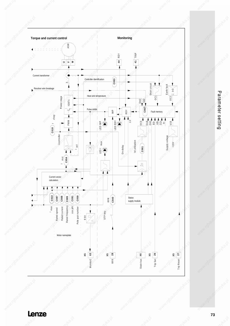
73
C08
7
C08
8
C08
9
C09
1
C02
2
C05
9
C09
3
C01
8
C05
4
cos
phi
Motor nameplate
PW
M
Pow
er s
tage
fch
op
Current vector calculation
IGB
Ts
8 bi
t
Mon
itor2
LED
Im
ax
Current transformer
Im
ot
Ixt u
tiliz
atio
n
C06
1
2863
C04
0
ST
P-k
ey
RF
R
RFR
IMP
LED
IMP
LED
RD
Y
RD
Y
C06
7
On-
dela
y
Status supply module
Sta
te b
usX
6
LU
OC
5
OU
EO
H1
Trip
Set
EE
r
OH
2
Sho
rt c
ircui
t
Ear
th fa
ult
Sd2 O
C1
OC
2
4144U V W
RD
Y
TR
IP
Pulse inhibit
iac
t
Heat sink temperature
Sup
ply
volta
ge
+15V
UE
rC
Cr
Pr
U15
27T
rip R
eset
Fault memory
AS
M
26
Torque and current control Monitoring
i-con
trolle
r
i
i=0
3
Rat
ed s
peed
Rat
ed c
urre
nt
Rat
ed fr
eque
ncy
Pol
e pa
ir nu
mbe
r
Resolver wire breakage
Controller identification
Im
ax
-1
X5
X5
X5
X5

74
Service
1. Monitoring messages
The servo drives of the 9200 series have numerous monitoringfunctions, to protect against non-permissible operating conditions.When such a protective function is activated, it either causes acorresponding message on the controller display and pulse inhibit(IMP) or, in addition (TRIP) setting. The type of fault is immediatelydisplayed. After having removed the fault, the pulse inhibit isreleased automatically. Faults, however, causing a TRIP settingmust be reset und C067 by pressing SH+PRG or by a high signalon input X5, terminal 27, TRIP reset.
1.1. Monitoring without activating pulse inhibit
• Following errorThe increments of the master frequency set value (Dig.Set) areinterpreted as angle increments (condition: Vpw>0). If the drivecannot follow the set increments the message "Following error"will be displayed as soon as a following error exceeds 3188increments (2048 increments ∉ 360° at the motor shaft). Theerror message disappears when the motor reaches the setangle. A following error >3188 increments cannot be corrected.
1.2. Monitoring with activating pulse inhibit
• LU UndervoltageThe mains voltage of the supply module is monitored bymeasuring the DC bus voltage. If the DC bus voltage decreasesbelow 330V ± 4%, the servo controllers cannot continue tooperate. The axis modules are inhibited via the State Bus. If themains voltage increases above 430V ± 3% again, the axismodules are released again.
1.3. Monitoring with TRIP setting
• OC1 Short circuitOC1 is displayed if the current controller of the axis modules isnot able to limit the output current of the controller to the peakcurrent. Check if there is a short circuit in the motor or the motorsupply cable.
• OC2 Earth faultAn earth fault current is detected if the total of the phase outputcurrent is not 0. Check if there is an earth fault in the motor orthe motor supply cable.
Caution:Before switching on the mains again, it must be ensured that theearth fault has been removed. The inverter free wheeling diodesmay be destroyed by earth faults.

75
• OC5 Overload axis module (I · t)The servo controllers can be overloaded up to their peak currentfor a certain period of time. The possible duration of overloadwithout Trip setting depends on its intensity. When exceedingthe time limit, the fault OC5 "overload" is displayed. Thecurrent/time ratios that do not lead to Trip setting are shown inthe overload diagrams below. These overload diagrammesshow permissible overcurrents, necessary recovery times andload cycles. Take into consideration that the rated currents ofthe axis modules depend on the chopper frequency set underC018 (see Technical data, page 6).
I1
I2
t1 t2
I1 > I nom : overload currentI2 < I nom : base load currentt1: duration of the overloadt2: duration of the base load
Overload chart for fchop = 8 kHz
Parameter I1/Irated Parameter I2/Irated
Example Agiven: fchop = 8kHz
overload I1 = 1,3 . Irated,t1 = 35sbase load I2 = 0,6 . Irated
required: minimum duration of the base load t2
result: t2 = 35s
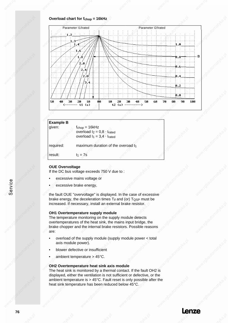
76
Overload chart for fchop = 16kHz
Parameter I1/Irated Parameter I2/Irated
Example Bgiven: fchop = 16kHz
overload I2 = 0,8 . Iratedoverload I1 = 3,4 . Irated
required: maximum duration of the overoad t1
result: t1 = 7s
OUE OvervoltageIf the DC bus voltage exceeds 750 V due to :
• excessive mains voltage or
• excessive brake energy,
the fault OUE "overvoltage" is displayed. In the case of excessivebrake energy, the deceleration times Tif and (or) TQSP must beincreased. If necessary, install an external brake resistor.
OH1 Overtemperature supply moduleThe temperature monitoring on the supply module detectsovertemperatures of the heat sink, the mains input bridge, thebrake chopper and the internal brake resistors. Possible reasonsare:
• overload of the supply module (supply module power < totalaxis module power).
• blower defective or insufficient
• ambient temperature > 45°C.
OH2 Overtemperature heat sink axis moduleThe heat sink is monitored by a thermal contact. If the fault OH2 isdisplayed, either the ventilation is not sufficient or defective, or theambient temperature is > 45°C. Fault reset is only possible after theheat sink temperature has been reduced below 45°C.

77
EEr External TRIPThe voltage at the TRIP-SET input X5 terminal 26 must be < 5V.Otherwise, the external TRIP will be set.
SD2 Wire breakage resolver or resolver cableThe electrical resistance of the resolver cables is monitored. If theline resistance is too high due to a line breakage or an interruptionin the resolver, fault SD2 "wire breakage" is displayed.
U15 Supply voltage interruptedCheck the Vcc-15V connection X5 terminal 20 for external shortcircuit.
CCr System faultProgramme sequence error in the micro processor. A system faultoccurs with interference in the electronics caused by incorrectscreening or non-screened cables or due to ground or earth loopsin the wiring. The fault may also occur after short mainsinterruptions (t < 1 min) if the controller was switched off while therewas another non-acknowledged fault.
Pr Parameter lossProgram sequence error in the microprocessor which is caused byinterference in the electronics due to incorrect screening or non-screened cables or ground or earth current loops in the wiring. Theinterference resulted the loss of the stored parameters. After TRIPreset and before enabling the controller again, a new parametersetting is required.
CEOCommunication error with the automation module. The error occurswhen the automation module is activated by C370-1, but thecommunication is interrupted.
UEr Unknown faultThis fault occurs in the fault memory if the hardware monitoringsets TRIP, however, the software cannot identify the fault (e.g. incase of interrupted supply voltage.

78
2. LED displays
The LED displays clearly indicate the momentary operating state ofthe controller even from greater distances. The axis modules areprovided with 3 LEDs in the operating terminal, the supply has 2LEDs at the front side.
2.1. LED supply module
RDY Ready to operateThe LED is illuminated after the ON-delay has passed and no faultwas detected. RDY is not illuminated if a fault was detected.
BRon Brake chopper activeThe LED is illuminated if the DC bus voltage is increased above athreshold by absorbing regenerated energy and then dissipatedthrough the brake resistor.
2.2. LED axis module
RDY Ready to operateThe LED is illuminated if the ON-delay has passed and no fault wasdetected. RDY is not illuminated if a fault was detected or homing isnot finished or the DC bus control is active or a following error isactive.
ImaxThe LED is illuminated when reaching the maximum controllercurrent or the set torque limit.
IMPPulse inhibit. The LED is illuminated if the inverter is inhibited. Theinverter is inhibited if the terminal 28 is low the STOP key ispressed, inhibit avtivated by communication or if a fault is detected.
RDY Imax IMP
on off off Controller is ready to operate, the controller is enabled
on off on Controller is ready to operate, however, it is not enabled
on on off Speed controller is limited:the controller supplies the set maximum current
First commissioning:If the motor speed remains at 50...300 rpm even at highset value and low load, the motor connection cables U andV must be exchanged.
off off on Controller is not ready to operate. In case of fault, the typeof fault is displayed.
off off off Maximum following error, homing not finished, active DC -bus control (see above)
off on off The maximum following error occured at master frequencycoupling and the controller reaches the set current limit.

79
3. Checking the power stage
The measurements described below are to be carried out only byskilled specialists. Use a digital voltmeter. The measuring valuesindicate the nominal value. If they are different from your measure-ments, there is a defect.
3.1. Checking the mains rectifier
• Disconnect the controller from the mains.
Caution!Wait 5 minutes until the DC-bus is discharged no load!
• Measure directly at the power terminals.
Measurement Measuring point Measuring value
Diodes in forwarddirection
L1 → +UGL2 → +UGL3 → +UG-UG → L1-UG → L2-UG → L3
≈ 0.4V≈ 0.4V≈ 0.4V≈ 0.4V≈ 0.4V≈ 0.4V
Diodes in reversedirection
+UG → L1+UG → L2+UG → L3L1 → -UGL2 → -UGL3 → -UG
high resistance (OL)high resistance (OL)high resistance (OL)high resistance (OL)high resistance (OL)high resistance (OL)
3.2. Checking the output stage
• Disconnect the controller from the mains.
Caution!Wait 5 minutes until the DC-bus is discharged!
• Measure directly at the power terminals.
Measurement Measuring point Measuring value
Inverter diode in forwarddirection
U → +UGV → +UGW → +UG
≈ 0.4V≈ 0.4V≈ 0.4V
Inverter diode in reversedirection
UG → UUG → VUG → W
high resistancehigh resistancehigh resistance
Inverter diode in forwarddirection
-UG → U-UG → V-UG → W
≈ 0.4V≈ 0.4V≈ 0.4V
Inverter diode in reversedirection
U → -UGV → -UGW → -UG
high resistancehigh resistancehigh resistance

80
Index
AAcceleration time 48Acceptance
direct 41On-line 41with SH + PRG 41with SH + PRG with controllerinhibit 42
Ambient temperature 6Amplification of the angle controller56Amplification of the differencecomponent of the speed controller 49Analog set value selection 22Angle offset 56Automation interface 71Axis module 7
BBasic parameter setting 45Baud rate 58Brake chopper active 78Brake resistor
external 33Brake resistor
external 18internal 20
CCEO 77Change parameters 41Checking the mains rectifier 79Checking the output stage 79Code table 63Commissioning 45cos ϕ motor 47
DDC-bus control 50Deceleration time 48Diagnosis 58
EEarth fault 74Electromagnetic combatibility 14Electromagnetic compatibility 14EMC 14Enclosure 6Encoder simulation 25Extended code set 41External Trip 77
FFollowing error 74Fuses 34
GGain adjustment 49Gearbox factor 46
HHoming mode 56
IInstallation
electrical 11mechanical 10

81
Integral action time of the speedcontroller 49Interference immunity 34
KKeypad control 45
LLCD display 40LECOM1 58LECOM2 58LECOM-LI 59LED
Axis module 78Supply module 78
MMains and DC-bus monitoring 20Mains connection 17Mains failure detection 50
activation 51
Mains isolation 14, 15, 59Mains status 20Mains voltage 6Master frequency 46Master frequency provision 46Master frequency selection 24Maximum current 48Maximum speed 48Monitoring 58Monitoring messages 74Motor connection 17Motor nameplate data 47Motors 39
NNoise immunity 6
OON-LINE 41Optical fibres 59Overload axis module 75Overtemperature heat sink 76Overtemperature supply module 76Overvoltage 76
PParameter setting 40, 41, 58Password 45Peak power 6Permanent brake power 18Planning 5Pollution strength 6Power connections 17Power stage 79
QQuick stop deceleration time 48
RRated motor current 47Rated motor frequency 47Rated motor speed 47Ready to operate 78relative humidity 6Resolver 25RFI filter 34RS 232 C 58RS 485 58
SSave parameters 42Screening 14serial communication 60Setting of speed controller 49Short circuit 74Standard code set 45State bus 21
82
Supply modules 6Supply voltage interrupted 77Switch-on display 57System cables 34
for control terminal block 34for power supply 37for resolver 36supply of fan and brake 38
System fault 77Systemcables
for master frequency selection 35
TTable of attributes 60Terminal control 45TRIP setting 74
UUndervoltage 74Unknown fault 77
WWire breakage resolver 77