Datasheet 1000BASE-SX SFP 850nm 550m DOM … · VeeR and VeeT may be internally connected within...
12
Features Application SFP1G-SX-85 Optical Communication System 1 Datasheet • Gigabit Ethernet • Fiber Channel • Switch to Switch Interface • Other Optical Links 1000BASE-SX SFP 850nm 550m DOM Transceiver • Operating Data Rate up to 1.25Gbps • 850nm VCSEL Laser Transmitter • 550m with 50/125µm MMF 300m on 62.5/125µm MMF • Single 3.3V Power Supply and LVTTL Logic Interface • Hot-Pluggable SFP Footprint Duplex LC Connector Interface • Class 1 FDA and IEC60825-1 Laser Safety Compliant • Commercial Temperature Range: 0~+70℃ • Compliant with SFP MSA Specification • Built-in digital diagnostic functions, including optical power monitoring
-
Upload
truongcong -
Category
Documents
-
view
220 -
download
0
Transcript of Datasheet 1000BASE-SX SFP 850nm 550m DOM … · VeeR and VeeT may be internally connected within...

Features
Application
SFP1G-SX-85
Optical Communication System
1
Datasheet
• Gigabit Ethernet• Fiber Channel• Switch to Switch Interface• Other Optical Links
1000BASE-SX SFP 850nm 550m DOM Transceiver
• Operating Data Rate up to1.25Gbps
• 850nm VCSEL Laser Transmitter• 550m with 50/125µm MMF
300m on 62.5/125µm MMF• Single 3.3V Power Supply and
LVTTL Logic Interface• Hot-Pluggable SFP Footprint
Duplex LC Connector Interface• Class 1 FDA and IEC60825-1 Laser
Safety Compliant• Commercial Temperature
Range: 0~+70• Compliant with SFP MSA
Specification• Built-in digital diagnostic
functions, including opticalpower monitoring

Optical Communication System
2
Datasheet
Description
Product Specifications
I. General Product Characteristics
The SFP1G-SX-85 series multi-mode transceivers are small form factor pluggable module for bi-directional serial optical data communications such as Gigabit Ethernet 1000BASE-SX and Fiber Channel FC-PH-2 for 100-M5-SN-1 and 100-M6-SN-1. It is with the SFP 20-pin connector to allow hot plug capability. This module is designed for multi-mode fiber and operates at a nominal wavelength of 850nm.
The transmitter section uses a Vertical Cavity Surface Emitted Laser (VCSEL) which is a Class 1 laser compliant according to International Safety Standard IEC 60825. The receiver section uses an integrated GaAs detector preamplifier (IDP) mounted in an optical header and a limiting post-amplifier IC.
Parameter Symbol Min Typ. Max Unit
Bit Rate BR 1.25 Gb/s
Max. Supported Link Length LMAX 550 m
II. Absolute Maximum Ratings
Parameter Symbol Min. Max. Unit
Storage Temperature Ts -40 +85
Supply Voltage Vcc -0.5 3.6 V
Operating Relative Humidity 95 %
*Exceeding any one of these values may destroy the device immediately.
+86 (755) 8300 3611 [email protected] www.fiberstore.com Page 4 of 4 +86 (755) 8300 3611 [email protected] www.fiberstore.com Page 4 of 6 +86 (755) 8300 3611 [email protected] www.fiberstore.com [email protected] FS.COM
Optical Communication System
3
Datasheet
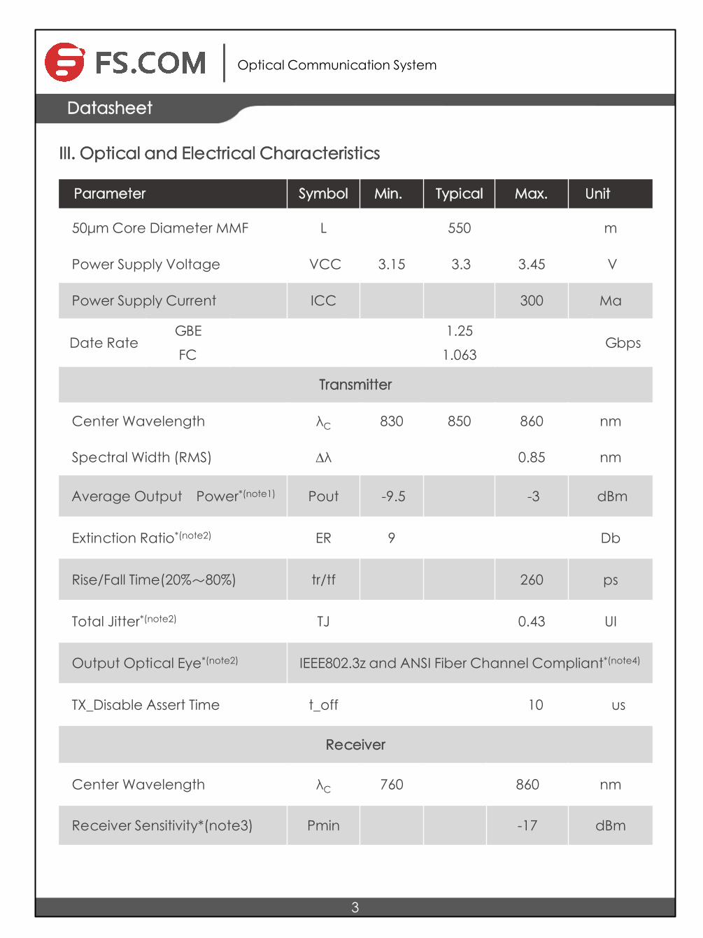
III. Optical and Electrical Characteristics
Parameter Symbol Min. Typical Max. Unit
50µm Core Diameter MMF L 550 m
Power Supply Voltage VCC 3.15 3.3 3.45 V
Power Supply Current ICC 300 Ma
Date Rate GBE 1.25
Gbps FC 1.063
Transmitter
Center Wavelength λC 830 850 860 nm
Spectral Width (RMS) Δλ 0.85 nm
Average Output Power*(note1) Pout -9.5 -3 dBm
Extinction Ratio*(note2) ER 9 Db
Rise/Fall Time(20%~80%) tr/tf 260 ps
Total Jitter*(note2) TJ 0.43 UI
Output Optical Eye*(note2) IEEE802.3z and ANSI Fiber Channel Compliant*(note4)
TX_Disable Assert Time t_off 10 us
Receiver
Center Wavelength λC 760 860 nm
Receiver Sensitivity*(note3) Pmin -17 dBm

Optical Communication System
Datasheet
4
Receiver Overload Pmax -3 dBm
Return Loss 12 Db
LOS De-Assert LOSD -18 dB
LOS Assert LOSA -35 dBm
LOS Hysteresis*(note5) 1 Db
Notes: 1. Output is coupled into a 62.5/125 mm multi-mode fiber.2. Filtered, measured with a PRBS 27-1 test pattern @1.25Gbps3. Minimum avera0ge optical power measured at BER less than 1E-12, with a 27-1
PRBS and ER=9 Db.4. Eye Pattern Mask
0 X1 X2 X3 1-X3 1-X2 1-X1 1
Nor
mal
ized
ampl
itude
1+Y4
1
1-Y11-Y20.5Y2Y1
0
-Y3
Normalized time(until interval)

Optical Communication System
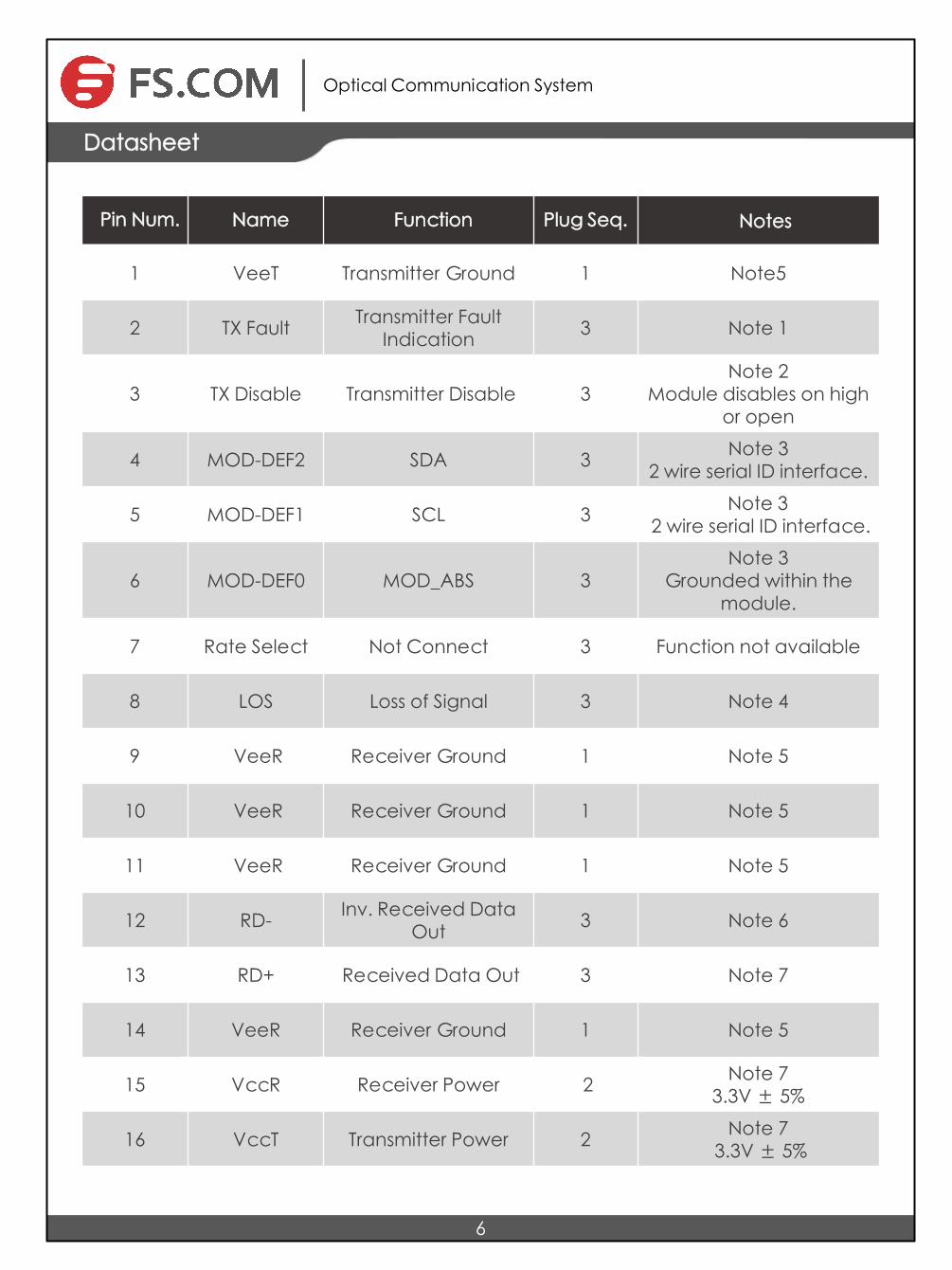
IV. Pin Description
5
Datasheet
5. LOS Hysteresis
Optical Communication System
6
Datasheet
Pin Num. Name Function Plug Seq. Notes
1 VeeT Transmitter Ground 1 Note5
2 TX Fault Transmitter Fault Indication 3 Note 1
3 TX Disable Transmitter Disable 3 Note 2
Module disables on high or open
4 MOD-DEF2 SDA 3 Note 3 2 wire serial ID interface.
5 MOD-DEF1 SCL 3 Note 3 2 wire serial ID interface.
6 MOD-DEF0 MOD_ABS 3 Note 3
Grounded within the module.
7 Rate Select Not Connect 3 Function not available
8 LOS Loss of Signal 3 Note 4
9 VeeR Receiver Ground 1 Note 5
10 VeeR Receiver Ground 1 Note 5
11 VeeR Receiver Ground 1 Note 5
12 RD- Inv. Received Data Out 3 Note 6
13 RD+ Received Data Out 3 Note 7
14 VeeR Receiver Ground 1 Note 5
15 VccR Receiver Power 2 Note 7 3.3V ± 5%
16 VccT Transmitter Power 2 Note 7 3.3V ± 5%

7
Optical Communication System
Datasheet
Notes: 1. TX Fault is an open collector/drain output, which should be pulled up with a 4.7KΩ
–10KΩ resistor on the host board. Pull up voltage between 2.0V and VccT, R+0.3V.When high, output indicates a laser fault of some kinds. Low indicates normal operation. In low state, the output will be pulled to < 0.8V.
2. TX disable is a n input that is used to shut d own the transmitter optical output. It is pulled up within the module with a 4.7KΩ – 10KΩ resistor. Its states are:Low (0 – 0.8V): Transmitter on(>0.8, < 2.0V): UndefinedHigh (2.0 – 3.465V): Transmitter DisabledOpen: Transmitter Disabled
3. Mod-Def 0,1,2. These are the module definition pins. They should be pulled up with a4.7KΩ – 10KΩ resistor on the host board. The pull-up voltage shall be VccT or VccR .Mod-Def 0 is grounded by the module to indicate that the module is present Mod-Def 1 is the clock line of two wire serial interface for serial IDMod-Def 2 is the data line of two wire serial interface for serial ID
4. LOS (Loss of Signal) is an open collector/drain output, which should be pulled upwith a 4.7KΩ – 10KΩ resistor. Pull up voltage between 2.0V and VccT/R+0.3V. Whenhigh, this output indicates the received optical power is below the worst-casereceiver sensitivity (as defined by the standard in use). Low indicates normaloperation. In the low state, the output will be pulled to < 0.8V.
5. VeeR and VeeT may be internally connected within the SFP module.
6. RD-/+: These are the differential receiver outputs. They are AC coupled 100Ωdifferential lines which should be terminated with 100Ω (differential) at the userSERDES. The AC coupling is done inside the module and is thus not required on thehost board. The voltage swing on these lines will be between 400 and 2000 mVdifferential (200 –1000 mV single ended) when properly terminated.
17 VeeT Transmitter Ground 1 Note 5
18 TD+ Transmit Data In 3 Note 8
19 TD- Inv. Transmit Data In 3 Note 8
20 VeeT Transmitter Ground 1 Note 5

8
Optical Communication System
Datasheet
VI. Mechanical Specifications
7. VccR and VccT are the receiver and transmitter power supplies. They are defined as3.3V ±5% at the SFP connector pin. Maximum supply current is 300mA.Recommended host board power supply filtering is shown below. Inductors with DCresistance of less than 1 ohm should be used in order to maintain the requiredvoltage at the SFP input pin with 3.3V supply voltage.
When the recommended supply-filtering network is used, hot plugging of the SFPtransceiver module will result in an inrush current of no more than 30mA greater thanthe steady state value. VccR and VccT may be internally connected within the SFPtransceiver module.
8.TD-/+: TD-/+: These are the differential transmitter inputs. They are AC-coupled,differential lines with 100Ω differential termination inside the module. The AC couplingis done inside the module and is thus not required on the host board. The inputs willaccept differential swings of 400 – 2000mV (200 – 1000mV single-ended).

Test Center
Only when quality and 100% compatibility is verified and proved do our modules enter the market. This depends on FS.COM's test center which is supported by a variety of mainstream original brand switches and professional staff. We are proud of this test center and believe all of these devices worth the investments, because it brings the best to our customers.
The original switches could be found nowhere but at FS.COM's test center, eg: Juniper MX960 & EX 4300 series, Cisco Nexus 9396PX & Cisco ASR 9000 Series, HP 5900 Series & HP 5406R ZL2 V3(J9996A), Arista 7050S-64, Brocade ICX7750-26Q & ICX6610-48, Avaya VSP 7000 MDA 2, etc.
Optical Communication System
9
Datasheet
ARISTA 7050S-64(DCS-7050S-64) Juniper MX960
Brocade ICX 7750-26Q Ex treme Networks X670V VIM-40G4X Mellanox M3601 Q
Cisco ASR 9000 Series(A9K-MPA-1X40GE)
Dell N4032F HP 5406R ZL2 V3(J9996A) AVAYA 7024XLS(7002QQ-MDA)

Test Assured Program
Our smart data system allows effective product management and qual i ty control according to the unique serial number, properly tracing the order, shipment and every part.
Our in-house coding facility programs all of our parts to standard OEM specs for compatibility on all major vendors and systems such as Cisco, Juniper, Brocade, HP, Dell, Arista and so on.
FS.COM truly understands the value of compatibility and interoperability to each optics. Every module FS.COM provides must run through programming and an extensive series of platform diagnostic tests to prove its performance and compatibility. In our test center, we care of every detail from staff to facilities—professionally trained staff, advanced test facilities and comprehensive original-brand switches, to ensure our customers to receive the optics with superior quality.
With a comprehensive line of original-brand switches, we can recreate an environment and test each optics in practical application to ensure quality and distance.
The last test assured step to ensure our products to be shipped with perfect package.
Optical Communication System
10
Datasheet

[email protected] FS.COM
Optical Communication System
11
Datasheet
Order Information
Note: Every transceiver is individually tested on corresponding equipment, walks through the testing challenges and 100% compatible with Cisco, Arista, Juniper, Dell, Brocade and other brands.
Part Number Description
SFP1G-SX- 85 SFP, 1000BASE-SX, 850nm, MMF, 550m, LC, DOM
SFP1G-SX-31 SFP, 1000BASE-SX, 1310nm, SMF, 2km, LC, DOM
SFP1G-LX-31 SFP, 1000BASE-LX, 1310nm, SMF, 10km, LC, DOM
SFP1G-LX-31 SFP, 1000BASE-LX, 1310nm, SMF, 15km, LC, DOM
SFP1G-LX-31 SFP, 1000BASE-LX/LH, 1310nm, SMF, 20km, LC, DOM
SFP1G-LH-31 SFP, 1000BASE-EX, 1310nm, SMF, 40km, LC, DOM
SFP1G-EX-55 SFP, 1000BASE-EX, 1550nm, SMF, 40km, LC, DOM
SFP1G-ZX-55 SFP, 1000BASE-EX, 1550nm, SMF, 60km, LC, DOM
SFP1G-ZX-55 SFP, 1000BASE-ZX, 1550nm, SMF, 80km, LC, DOM
SFP1G-EZX-55 SFP, 1000BASE-EZX, 1550nm, SMF, 100km, LC, DOM
SFP1G-EZX-55 SFP, 1000BASE-EZX, 1550nm, SMF, 120km, LC, DOM
SFP-GB-T SFP, 1000BASE-T, SERDES/SGMII Interface
SFP-GB-T SFP, 10/100/1000BASE-T, SERDES Interface

Fiberstore U.K. Third Floor 207 Regent Street, London, W1B 3HH, United Kingdom Tel: +44 (020) 3287 6810
Fiberstore U.S. 331 Andover Park East Ste330, Tukwila, WA 98188, United States Tel: +1-425-226-2035 Fax: +1-253-246-7881
Fiberstore Hong Kong 1220 Tung Chun Commercial Centre, 438-444 Shanghai Street, Kowloon, HongKong Tel: +(852) 817 636 06 Fax: +(852) 817 636 06
Fiberstore China Room 301, Third Floor, Weiyong Building, No. 10 Kefa Road, Nanshan District, Shenzhen, 518057, China Tel: +86 (755) 8300 3611 Fax: +86 (755) 8326 9395
Addresses, phone number and fax number also have been listed at www.fs.com. Please e-mail us at [email protected] or call us for assistance.
All statements, technical information, and recommendations related to the products here are based upon information believed to be reliable or accurate. However, the accuracy or completeness thereof is not guaranteed, and no responsibility is assumed for any inaccuracies. Please contact FS for more information.
Contact Us
Fiber Optic Transceivers Copyright © 2009-2016 FS.COM All Rights Reserved.
Optical Communication System
Datasheet