Datablad for BMS 8S 24V 100A - njordnautic.dk
8
Datablad for BMS 8S 24V 100A
Transcript of Datablad for BMS 8S 24V 100A - njordnautic.dk
Datablad for BMS 8S 24V 100A
DL-R05U-F04S100ATJ-MM04-S4RV
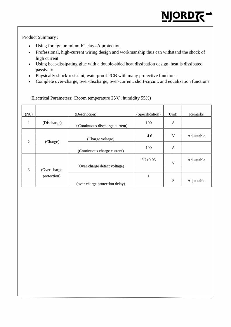
Product Summary:
• Using foreign premium IC class-A protection.
• Professional, high-current wiring design and workmanship thus can withstand the shock of
high current
• Using heat-dissipating glue with a double-sided heat dissipation design, heat is dissipated
passively
• Physically shock-resistant, waterproof PCB with many protective functions
• Complete over-charge, over-discharge, over-current, short-circuit, and equalization functions
Electrical Parameters: (Room temperature 25℃, humidity 55%)
(N0) (Description) (Specification) (Unit) Remarks
1 (Discharge)
100
A
(Continuous discharge current)
14.6
V
(Charge voltage)
Adjustable
2 (Charge)
100
A
(Continuous charge current)
3.7±0.05 V
Adjustable
(Over charge detect voltage)
3 (Over charge
protection) 1 S
(over charge protection delay)
Adjustable
DL-R05U-F04S100ATJ-MM04-S4RV
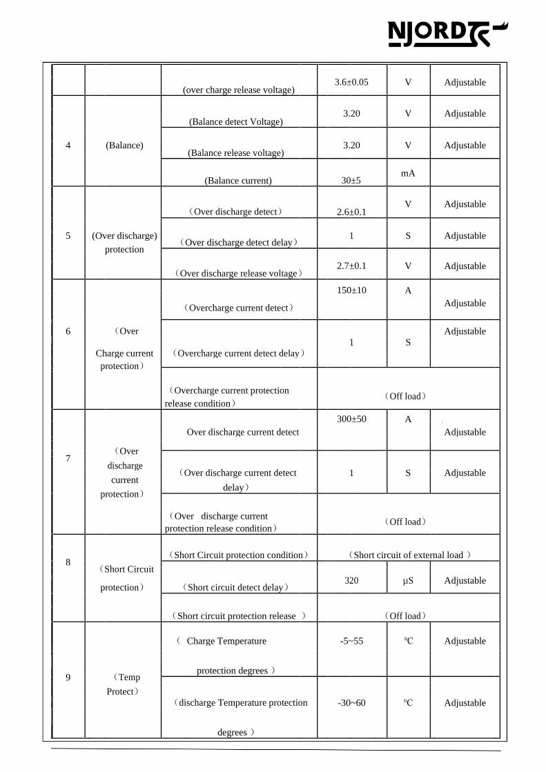
3.6±0.05
V
(over charge release voltage)
Adjustable
3.20
V
(Balance detect Voltage)
Adjustable
4
(Balance)
3.20
V
(Balance release voltage)
Adjustable
mA
(Balance current)
30±5
V
(Over discharge detect)
2.6±0.1
Adjustable
5
(Over discharge)
1
S
(Over discharge detect delay)
Adjustable
protection
2.7±0.1
V
(Over discharge release voltage)
Adjustable
150±10
A
(Overcharge current detect)
Adjustable
6
(Over 1
S
Adjustable
Charge current (Overcharge current detect delay)
protection)
(Overcharge current protection
(Off load)
release condition)
300±50 A
Over discharge current detect
(
Adjustable
7
(Over
discharge
(Over discharge current detect
1
S
Adjustable
current
delay)
protection)
(Over discharge current
(Off load)
protection release condition)
8
(Short Circuit protection condition) (Short circuit of external load )
(Short Circuit
320
µS
protection) (Short circuit detect delay) Adjustable
(Short circuit protection release ) (Off load)
( Charge Temperature -5~55 ℃ Adjustable
protection degrees )
9
(Temp
Protect)
(discharge Temperature protection
-30~60
℃
Adjustable
degrees )
DL-R05U-F04S100ATJ-MM04-S4RV
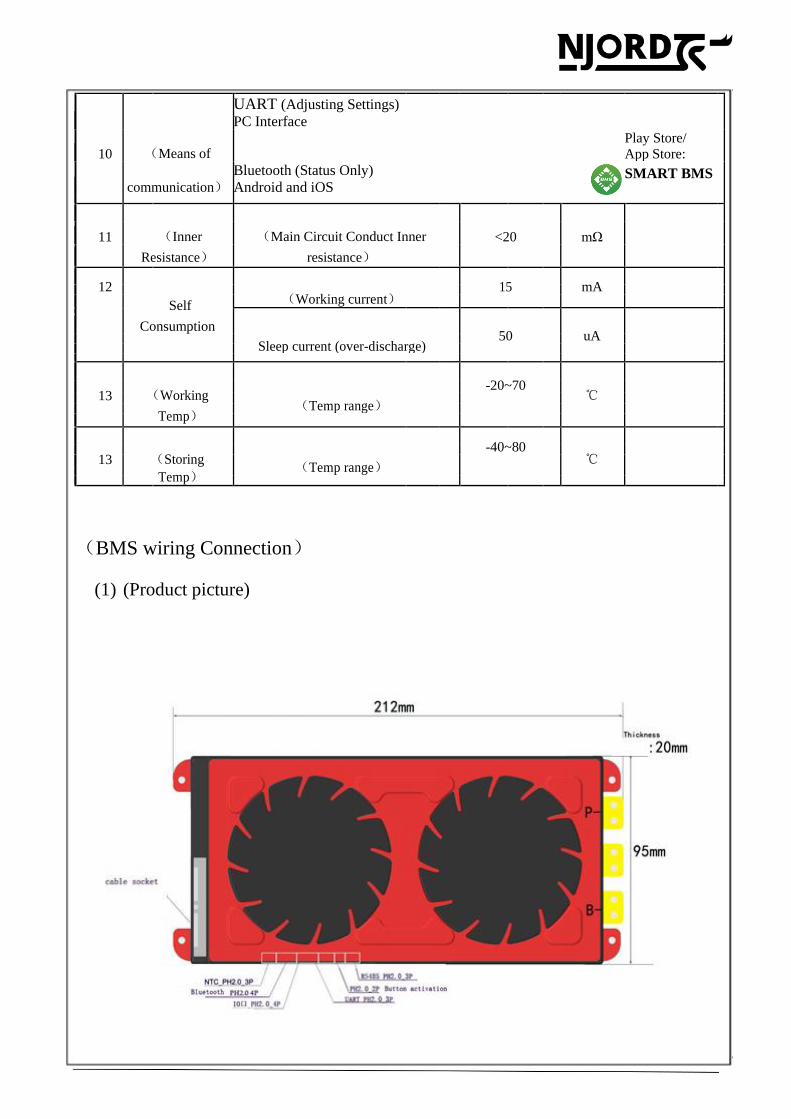
UART (Adjusting Settings)
PC Interface
10 (Means of Play Store/
App Store:
communication)
Bluetooth (Status Only)
Android and iOS SMART BMS
DalyBMS
11 (Inner (Main Circuit Conduct Inner <20 mΩ
Resistance) resistance)
12
15
mA
(Working current)
Self
Consumption 50
uA
Sleep current (over-discharge)
-20~70
13 (Working
℃
(Temp range)
Temp)
-40~80
13 (Storing
℃
(Temp range)
Temp)
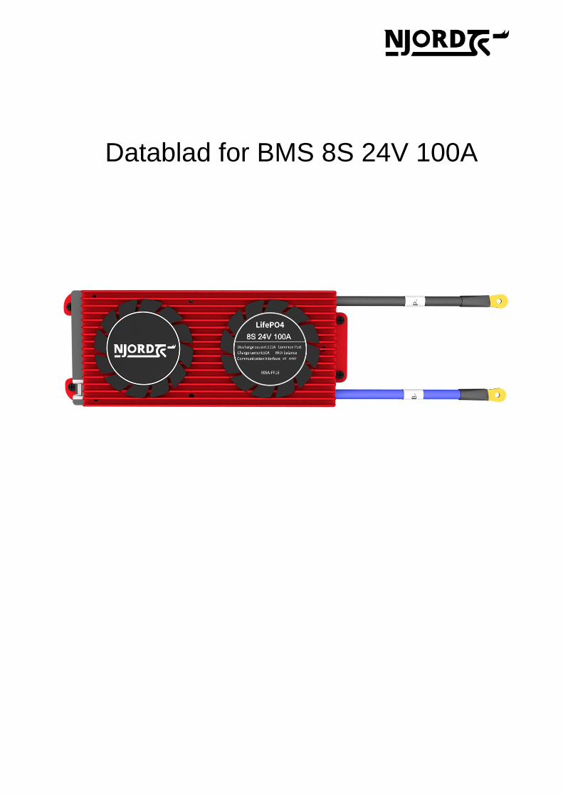
(BMS wiring Connection)
(1) (Product picture)
DL-R05U-F04S100ATJ-MM04-S4RV
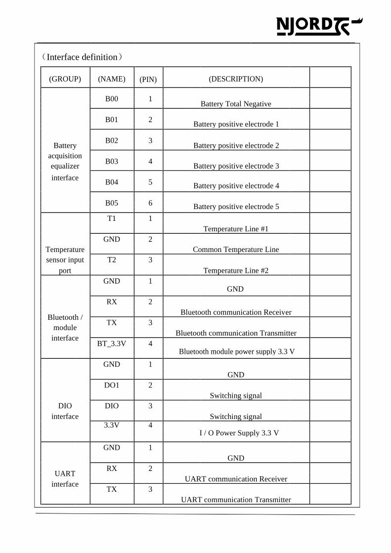
(Interface definition)
(GROUP) (NAME) (PIN) (DESCRIPTION)
B00
1
Battery Total Negative
B01
2
Battery positive electrode 1
B02
3
Battery
Battery positive electrode 2
acquisition B03
4
equalizer
Battery positive electrode 3
interface B04
5
Battery positive electrode 4
B05
6
Battery positive electrode 5
T1 1
Temperature Line #1
GND 2
Temperature Common Temperature Line
sensor input T2 3
port Temperature Line #2
GND 1
GND
RX
2
Bluetooth communication Receiver
Bluetooth /
TX
3
module
Bluetooth communication Transmitter
interface
BT_3.3V
4
Bluetooth module power supply 3.3 V
GND 1
GND
DO1 2
Switching signal
DIO DIO 3
interface Switching signal
3.3V 4
I / O Power Supply 3.3 V
GND 1
GND
RX
2
UART
UART communication Receiver
interface
TX
3
UART communication Transmitter
DL-R05U-F04S100ATJ-MM04-S4RV
KEY 1
Key Key switch
switch GND 2
GND
485T_B 1
485 Communications B
485 interface 485T_A 2 485 Communications A
AGND 3 GND
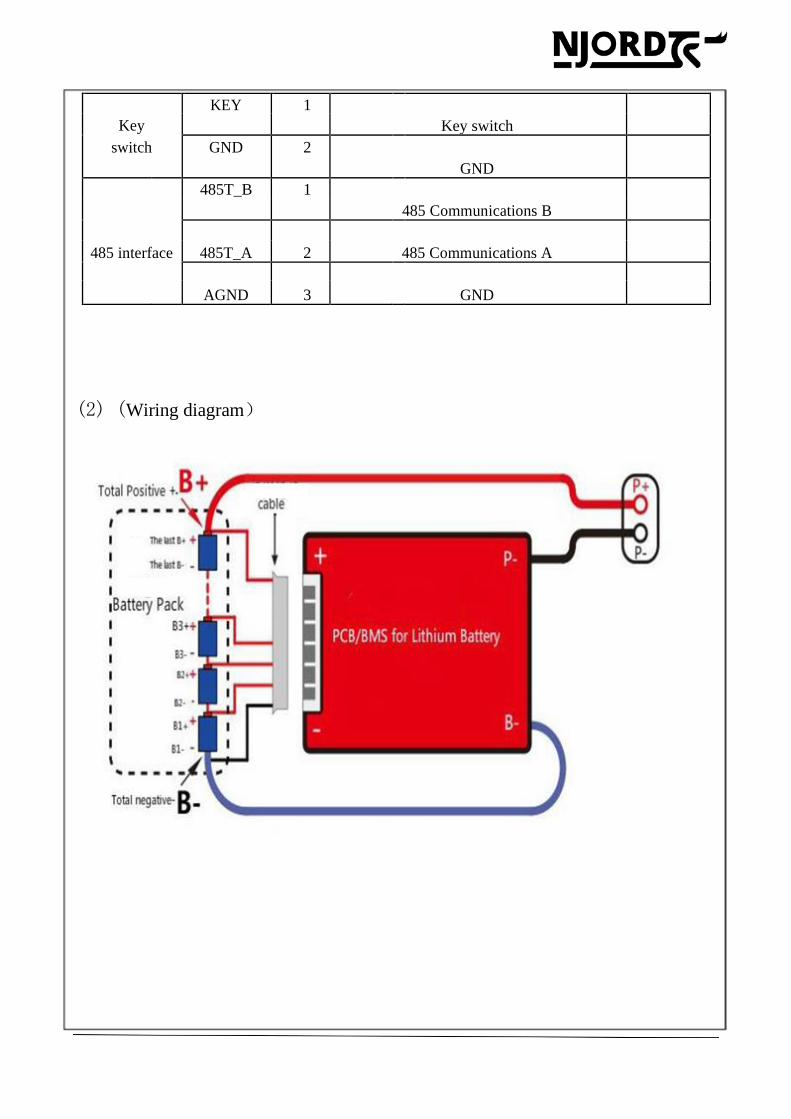
(2) (Wiring diagram)
DL-R05U-F04S100ATJ-MM04-S4RV
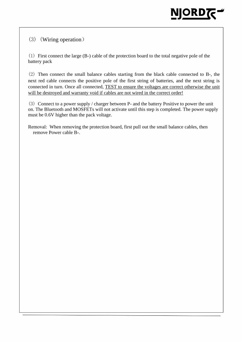
(3) (Wiring operation)
(1) First connect the large (B-) cable of the protection board to the total negative pole of the
battery pack
(2) Then connect the small balance cables starting from the black cable connected to B-, the
next red cable connects the positive pole of the first string of batteries, and the next string is
connected in turn. Once all connected, TEST to ensure the voltages are correct otherwise the unit
will be destroyed and warranty void if cables are not wired in the correct order!
(3) Connect to a power supply / charger between P- and the battery Positive to power the unit on. The Bluetooth and MOSFETs will not activate until this step is completed. The power supply must be 0.6V higher than the pack voltage.
Removal: When removing the protection board, first pull out the small balance cables, then
remove Power cable B-.
DL-R05U-F04S100ATJ-MM04-S4RV
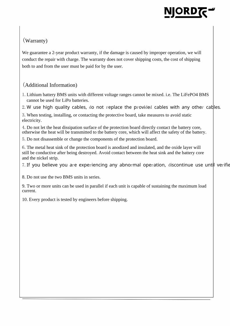
(Warranty)
conduct the repair with charge. The warranty does not cover shipping costs, the cost of shipping
both to and from the user must be paid for by the user.
(Additional Information)
1.Lithium battery BMS units with different voltage ranges cannot be mixed. i.e. The LiFePO4 BMS
cannot be used for LiPo batteries.
3.When testing, installing, or contacting the protective board, take measures to avoid static
electricity.
4.Do not let the heat dissipation surface of the protection board directly contact the battery core, otherwise the heat will be transmitted to the battery core, which will affect the safety of the battery.
5.Do not disassemble or change the components of the protection board.
6.The metal heat sink of the protection board is anodized and insulated, and the oxide layer will
still be conductive after being destroyed. Avoid contact between the heat sink and the battery core
and the nickel strip.
9. Two or more units can be used in parallel if each unit is capable of sustaining the maximum load current.
2.W use high quality cables, d o not r eplace the pr ovid ed cables with any other cables.
7.If you believe you ar e exper iencing any abnor mal oper ation, d iscontinue use until ver ified ok
We guarantee a 2-year product warranty, if the damage is caused by improper operation, we will
8. Do not use the two BMS units in series.
10. Every product is tested by engineers before shipping.