Database Management Systems -...
96
UNIT III 1 Database Management Systems
Transcript of Database Management Systems -...

UNIT III
1
Database Management
Systems

Database Management Systems (DBMS)
• Objectives:
– To know the ANSI/SPARC architecture for database
management systems.
– To know the concept of data independence in databases and
2
– To know the concept of data independence in databases and
the associated mechanisms.
– To know the mechanisms and strategies for integrity control
(quality) and security (privacy) in databases.
– To know (basically) the physical organisation of a relational
database.
Database Management Systems (DBMS)
Syllabus
3.1.- Database Management Systems: components and functionalities.
3.2.- Data independence.
3.3.- Integrity.
3.3.1.- Concept of transaction. Transaction processing.
3.3.2.- Semantic integrity.
3
3.3.2.- Semantic integrity.
3.3.3.- Concurrent accesses
3.3.4.- Database recovery
3.4.- Security.
3.4.1.- User control
3.4.2.- Authorised access control
3.5.- Relational database implementation

3.1.- Database Management System
• DBMS: Software which allows the creation and manipulation of
databases.
DBMS
Is based on
4
data model (relational model)
data structures and associated operators
Is composed of

– a unified description of the data and independent of the
applications
– application independence with respect to the physical data
representation
3.1.1.- Components and functions of a DBMS
DBMS’s allow for:
5
representation
– definition of partial data views for different users
– information management
– data integrity and security

3.1.1.- Components and functions of a DBMS.
Objectives of DB techniques
• Unified and independent data
description
DBMS Functions
Data definition at several
levels:
DBMS Components
Schema definition
languages and their
associated translators
6
• Application independence
• Partial view definition
• logical schema
• internal schema
• external schema
associated translators

3.1.1.- Components and functions of a DBMS.
Objectives of DB techniques
Information management
DBMS Functions
Data manipulation:
• query
• update
DBMS Components
Manipulation languages
and their associated
translators
7
• update
Management and
administration of the
database
Tools for:
• restructuring
• simulation
• statistics
• printing and
reporting

Objectives of DB techniques
Data integrity and
security
DBMS Functions
Control of:
• semantic integrity
DBMS Components
Tools for:
• integrity control
• reconstruction
3.1.1.- Components and functions of a DBMS.
8
security• concurrent access
• recovery in case of
failure
• security (privacy)
• reconstruction
• security control

3.1.2.- Schema of DBMS data access
DBMS
Application 1 Application 2 Application 3
Data
independence
Unified Data
Description
External schemas
Logical schema
9
DBMS
OS
• Security Control
• Semantic Integrity Control
• Concurrent Access Control
• Reconstruction
DBIntegration of
all the system’s
information
Persistence
independence (specification)
Internal schema
(implementation)
Commands and dataflows
DBMS look-ups to the
data definition

External schema for application 1:
CREATE VIEW Clerk (id, name, monthly_salary)
AS SELECT id, name, annual_salary/14
FROM Employee
WHERE type=‘CK’
3.1.2.- Schema of DBMS data access
10
Logical schema:
Employee(id, name, address, annual_salary, type)
PK: {id}
Internal schema:
Ordered file Employee with primary index over the id field and
the path h:/disk1/freaky

Application 1: accesses the information through the external
schema 1
SELECT name, monthly_salary
FROM Clerk
3.1.2.- Schema of DBMS data access
11
WHERE id = parameter
DBMS: access control and resolution of the issued command
OS:Manipulation of the device drivers which handle the
secondary storage

3.1.2.- Schema of DBMS data access
Application 1
External schema 1
1. Query over the data structures of the external schema 1
User 1
data area for application 1
7. Data
working area for
12
DB
DBMS
OS file manager
Logical schema
Internal schema
OS I/O manager
2. Correspondence between schemas
3.Asks for a record from data file
4. Asks for a data block from disk
5. I/O operation
memory buffers
block
6. record
command
data flow
operation
working area for the DBMS

3.1.2.- EXAMPLE. SpecificationA small estate agency wants to maintain information about the houses it sells and hires. We
want to know:
– For each house, its code, location, district, owner, price and agent who is in charge of
selling it.
– For each owner, his/her code, name and phone.
– For each agent, his/her ID, name, sale commission, service years in the company and
telephone.
13
telephone.
Constraints that must be met:
– The commission of an agent cannot exceed 3% if his/her service years are less than 3
years.
– We don’t want information about owners if they do not have at least one house for sale.
Work groups:
– The clerk staff has access to all the information above (except writing the agent info).
– The boss of the estate agency only requires information about the houses with a price
over 5 millions. For each, she/he requires the code, location and district.
– The boss is the only one who can modify the agent’ s information.

3.1.2.- EXAMPLE. Logical schema (SQL)
CREATE SCHEMA EstateAgency
CREATE TABLE House
(Code code_d PRIMARY KEY, Location loc_d NOT NULL,
District dis_d NOT NULL, Price pri_d NOT NULL,
Agent_id id_d FOREIGN KEY REFERENCES Agent
ON UPDATE CASCADE, ON DELETE NO ACTION
14
ON UPDATE CASCADE, ON DELETE NO ACTION
Owner code_d NOT NULL, FOREIGN KEY(Owner) REFERENCES Owner(code)
ON UPDATE CASCADE ON DELETE CASCADE)
CREATE TABLE Owner
(Code code_d PRIMARY KEY, Name name_d NOT NULL, Telephone tel_d NOT NULL)
CREATE TABLE Agent
(agent_id id_d PRIMARY KEY, commission com_d, year year_d NOT NULL,
Tel tel_d NOT NULL, CHECK NOT (year < 3 AND commission > 3))
CREATE ASSERTION no_owner_without_houses CHECK NOT EXISTS
(SELECT * FROM Owner WHERE code NOT IN (SELECT Owner FROM House))
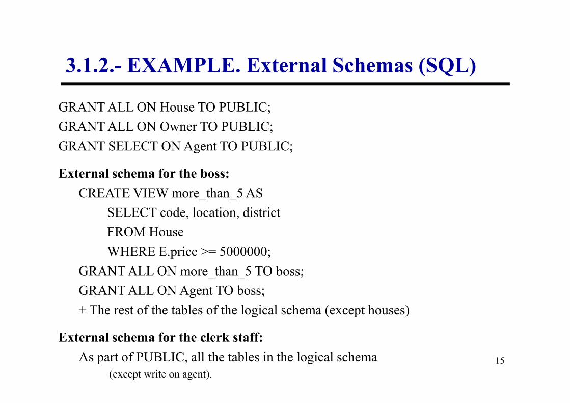
3.1.2.- EXAMPLE. External Schemas (SQL)
GRANT ALL ON House TO PUBLIC;
GRANT ALL ON Owner TO PUBLIC;
GRANT SELECT ON Agent TO PUBLIC;
External schema for the boss:
CREATE VIEW more_than_5 AS
15
SELECT code, location, district
FROM House
WHERE E.price >= 5000000;
GRANT ALL ON more_than_5 TO boss;
GRANT ALL ON Agent TO boss;
+ The rest of the tables of the logical schema (except houses)
External schema for the clerk staff:
As part of PUBLIC, all the tables in the logical schema
(except write on agent).

3.1.2.- EXAMPLE. Physical Schema
House :
Hash file by agent_id
B+ index over (district + price)
Owner
16
Hash file by code
B+ index over name
Agent
Disordered file (we assume few agents).
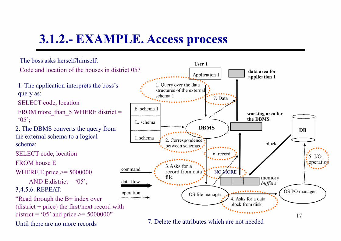
3.1.2.- EXAMPLE. Access process
The boss asks herself/himself:
Code and location of the houses in district 05?
1. The application interprets the boss’s
query as:
SELECT code, location
FROM more_than_5 WHERE district =
‘05’;
Application 1
L. schema
E. schema 1
1. Query over the data structures of the external schema 1
User 1
data area for application 1
7. Data
working area for the DBMS
17
‘05’;
2. The DBMS converts the query from
the external schema to a logical
schema:
SELECT code, location
FROM house E
WHERE E.price >= 5000000
AND E.district = ‘05’;
3,4,5,6. REPEAT:
“Read through the B+ index over
(district + price) the first/next record with
district = ‘05’ and price >= 5000000”
Until there are no more records 7. Delete the attributes which are not needed
NO MORE
DB DBMS
OS file manager
L. schema
I. schema
OS I/O manager
2. Correspondence between schemas
3.Asks for a record from data file
4. Asks for a data block from disk
5. I/O operation
memory buffers
block
6. record
command
data flow
operation
the DBMS
.
3.2.- Data independence.
Property which ensures that the application programs
are independent of the changes which are performed
18
are independent of the changes which are performed
on data which are not used or in physical
representation details of the accessed data.

Proposal of a DBMS architecture by the working group
ANSI/SPARC (1977): they propose the database definition with
three levels of abstraction:
– Conceptual Level⇒ Conceptual schema
• Description of the DB independently of the DBMS
3.2.- Data independence.
19
– Internal Level⇒ Internal schema
• Description of the DB in terms of its physical
representation
– External Level⇒ External schemas
• Description of the partial views which the different users
have on the DB

Since there was no generalised conceptual model which was accessible
to different kinds of DBMS, a new level was introduced:
– Conceptual Level⇒ Conceptual schema
• Organisational DB description
– Logical Level ⇒ Logical schema
3.2.- Data independence.
20
• DB description in terms of the DBMS data model
– Internal Level⇒ Internal schema
• DB description in terms of its physical representation
– External Level⇒ External schemas
• Description of the partial views which the different users have
on the DB

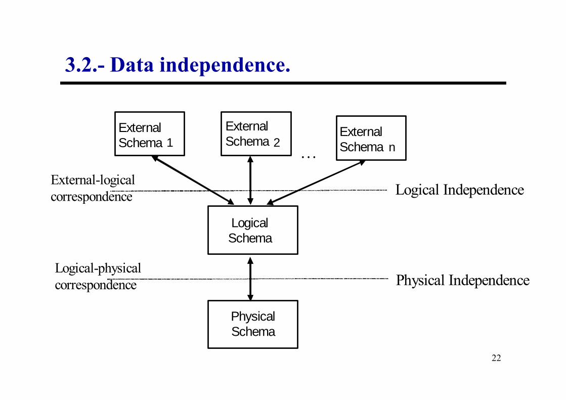
A DBMS which complies with this architecture level must:
– Supply tools to define the several schemas in the database
(except the conceptual schema)
– Establish the correspondence between schemas.
– Isolate the schemas: the changes in one schema must not
3.2.- Data independence.
21
– Isolate the schemas: the changes in one schema must not
affect the schemas at upper levels and, hence, neither do they
affect the application programs.
Data independence
1 2 n …
Logical Independence External-logical
correspondence
External Schema
External Schema
External Schema
3.2.- Data independence.
22
Physical Independence
correspondence
Logical-physical
correspondence
Logical Schema
Physical Schema
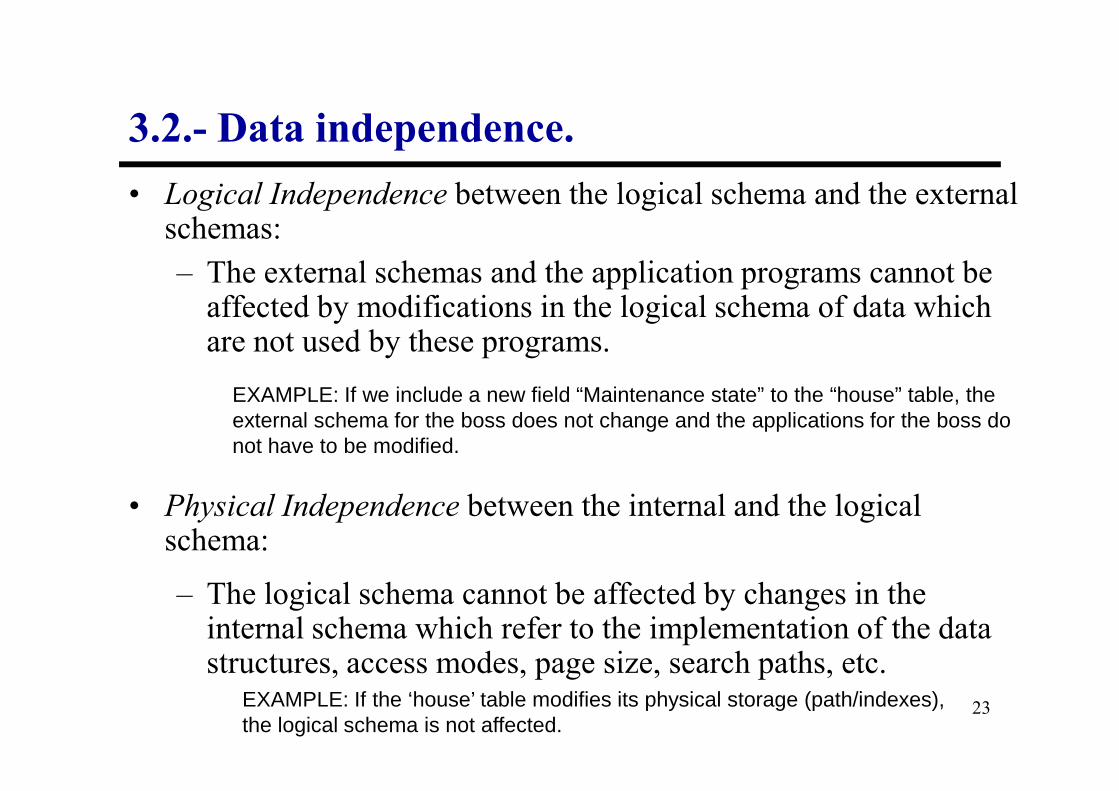
• Logical Independence between the logical schema and the external schemas:
– The external schemas and the application programs cannot be affected by modifications in the logical schema of data which are not used by these programs.
3.2.- Data independence.
EXAMPLE: If we include a new field “Maintenance state” to the “house” table, the
23
• Physical Independence between the internal and the logical schema:
– The logical schema cannot be affected by changes in the internal schema which refer to the implementation of the data structures, access modes, page size, search paths, etc.
EXAMPLE: If we include a new field “Maintenance state” to the “house” table, the external schema for the boss does not change and the applications for the boss do not have to be modified.
EXAMPLE: If the ‘house’ table modifies its physical storage (path/indexes), the logical schema is not affected.

BINDING:
– Transformation of the external schema into the internal
schema.
–Logical binding (steps 2 and 7).
3.2.- Data independence.
24
–Logical binding (steps 2 and 7).
–Physical binding (steps 3 and 6).
– When binding is performed, independence disappears.
It is important to determine this moment
Types

Application program:
– Binding in compilation time:
◊ Transformation of the external schema used by the
program in terms of the internal schema.
◊
3.2.- Data independence.
25
◊ Any change in the logical and/or physical schema
requires a re-compilation.
– Binding when executing the program:
◊ It does not require any action over the program.

3.2.- Data independence.
Binding moment:
• during compilation or pre-compilation
• during linkage
• when the execution starts or in the moment the connection is
26
• when the execution starts or in the moment the connection is
established
• in each database access
More independence: the later the binding is
Less cost: the earlier the binding is
3.3.- Integrity
• One objective of database technology
• Information quality:
“data must be structured in such a way as to adequately reflect
the objects, relations and constraints which exist in the parcel
27
the objects, relations and constraints which exist in the parcel
of the world which the database models”
• Representation of objects, relations and constraints in the database
schema.
• Reality changes → User updates
• The information contained in the database must preserve the schema
definition.

3.3.- Integrity
• Information quality (integrity perspective):
– The DBMS must ensure that the data are stored correctly.
– The DBMS must ensure that user updates over the database are
executed correctly and become permanent.
28
executed correctly and become permanent.

3.3.- Integrity
DBMS tools oriented towards integrity:
–Check (wrt. updates) the integrity constraints defined in the
schema.
29
–Control the correct execution of the updates (in a concurrent
environment).
–Recover (reconstruct) the database in case of losses or accidents.

3.3.- Integrity: concurrent accesses
Accounts
123 1000 555 2000
No. Balance Time P1 P2
t1 read(123, balance)
t2 read(123, balance)
30
t2 read(123, balance)
t3 balance←balance-100
t4 balance←balance-200
t5 write(123, balance)
t6 write(123, balance)
No.
Accounts
123 800 555 2000
Balance

3.3.- Integrity: recovery
Accounts
Backup (12-12-03)
13-12-03: Update on accounts
31
transaction no. 51: system failure!
Recovery Procedure:• Replace the file Accounts with its backup
Negative Effect:• The updates of 50 transactions are lost

3.3.- Integrity: transactions
• Database integrity must be controlled when access operations take
place, generally coming from the applications.
• The access operations to a database are organised in transactions.
32
Sequence of access operations to the
database which constitute a logical
execution unit.
TRANSACTION

3.3.- Integrity: transactions
Emp(id, name, addr, dept)
PK: {id}
FK: {dept} → Dep
Dep(code, name, location)
PK: {code}
33
PK: {code}
R1: ∀Dx:Dep (∃Ex:Emp (Dx.cod = Ex.dept ))
Insertion of a new department:
<d2, “Human Resources”, “3rd Floor”>
whose first employee is the id 20

3.3.- Integrity: transactions
1) insertion in Dep:
2) modification of Emp over the tuple with id 20
ERROR: the constraint R1 is violated
<d2, “Human Resources”, “3rd floor”>
1st
Idea
34
1) modification de Emp over the tuple with id 20
2) insertion en Dep:
ERROR: the foreign key over dept in Emp is violated
<d2, “Human Resources”, “3rd floor”>
2nd
Idea

3.3.- Integrity: transactions
Basic operations in a transaction which are relevant to the
DBMS:
– read(X): reading or access to a piece of data X in the
database over the program variable with the same
35
database over the program variable with the same
name
– write(X): update (insertion, deletion or modification)
of a piece of data X in the database by using the
program variable with the same name

3.3.- Integrity: transactions
Basic operations in a transaction which are relevant to the
DBMS:
– read(X):
36
1. Seek the address of the block which contains the
data X
2. Copy the block to a buffer in main memory
3. Copy the data X from the buffer to the program
variable X

3.3.- Integrity: transactions
Basic operations in a transaction which are relevant to the
DBMS:
– write(X):
1. Seek the address of the block which contains the data X
37
1. Seek the address of the block which contains the data X
2. Copy the block to a buffer in main memory
3. Copy the data X from the program variable to the
suitable location in the buffer
4. Copy the updated block from the buffer to the disk
If not read before
3.3.- Integrity: transactions
Actions which change transaction states:
• begin: indicates the start of a transaction
• end: indicates that all the operations in the transaction have
been completed.
38
been completed.
• confirmation: indicates the success of the transaction, making
the DBMS store the changes performed on the database
• cancellation: indicates the failure of the transaction due to some
reason. The DBMS undoes all the possible changes performed
by the transaction

3.3.- Integrity: transactions
begin end active confirmed
confirmation
confirmation pending
39
failed
cancellation
cancellation
finished
action
state

3.3.- Integrity: transactions
(ACID) Properties which all transactions must comply with:
• atomicity: a transaction is an atomic execution unit (either all or
none of the operations are performed)
• consistency: the transaction must yield a consistent state for the
database (all integrity constraints must be met)
40
database (all integrity constraints must be met)
• isolation: the modifications introduced by a non-confirmed
transaction are not visible by other transactions
• durability: confirmation implies the recording of the changes
performed on the database, in such a way that they cannot be lost
due to system failure or other transactions

3.3.- Integrity: transactions
Two kinds of transaction implementation (depending on
the DBMS):
• Immediate Update: updates have an immediate effect
on secondary memory. In case of cancellation, they
have to be undone.
41
have to be undone.
• Deferred Update: updates only have immediate effect
on main memory. The updates are only transferred to
secondary memory when confirmed.

3.3.- Integrity: semantic integrity
• Integrity constraint:
Property of the real world which is modelled by the
database
• Constraints are defined in the logical schema and the
42
• Constraints are defined in the logical schema and the
DBMS must ensure that they are met.
• Checking is performed whenever the database changes (an
update operation is executed).
• Constraints not included in the database schema must be
maintained by the application programs.

3.3.- Integrity: semantic integrity
• Types of integrity constraints:
– static: they must be met in each state of the database
(they can be represented by logical expressions)
43
(they can be represented by logical expressions)
– transition: they must be met regarding two consecutive
states.
EXAMPLES: Domain definitions, PK, FK, NNV, UNIQUE, Assertions, ...
EXAMPLE: The price of a house cannot diminish.

3.3.- Integrity: semantic integrity
• SQL/92 constraints:
– static:
◊ over domains: value constraint.
◊ over attributes: not null value, range, etc.
◊ over relations: primary key, uniqueness and foreign keys.
44
◊ over relations: primary key, uniqueness and foreign keys.
◊ over the database: general search conditions* (Assertions)
• when are they checked?
• does the system take any compensatory action?
–transition: they must be met regarding two consecutive states *
* (they’re not usually implemented by commercial systems)
After each instruction (IMMEDIATE)
At the end of the transaction (DEFERRED)

3.3.- Integrity: semantic integrity
• Procedures for integrity checking (rules, triggers, ...) :
–The way in which integrity is checked is delegated to the
designer
–Make it possible to incorporate complex (and transition)
constraints into the database schema.
45
constraints into the database schema.
–The procedures must include:
◊Operations which trigger it (the event and condition)
◊Code to be executed, which usually includes instructions over
the database.
◊Actions for rejection or compensation in case of constraint
violation.

3.3.- Integrity: concurrent access control
• The DBMS must control the concurrent access by the
applications.
• Problems due to interference of concurrent accesses:
46
• Problems due to interference of concurrent accesses:
a) Loss of updates,
b) Incoherent information corresponding to several valid database
states, and
c) Access to updated data (but still not confirmed) that can still be
cancelled.

3.3.- Integrity: concurrent access control
a) Loss of updates
...
A0 B0 ... ...
...
RP1 P2
Read(R(A0,B0, ...)
47
...
time
Read(R(A0,B0, ...)
Read(R(A0,B0,...))
Write(R(A1,B0,...))
Write(R(A0,B1,...))
A0 :- A1
B0 :- B1
The instruction “Write(R(A1,B0))” is lost !!!!

3.3.- Integrity: concurrent access control
b) Incoherent information
C1 C= 200000
C2 ... ..
Accounts
P1 P2Read(C1, Balance)
P1: Access to the balance total
P2: Transfer from account 100 to account 1.
48
C100 C= 200000 ..
time
Read(C1, Balance)...
Read(C100)
Write(C100, Balance = Balance – X)
Read(C1)
Write(C1, Balance = Balance + X)
......
Read(C99, Balance)
Read(C100, Balance)
Read(C2)
...
ERROR!! There are X euros missing in P1.
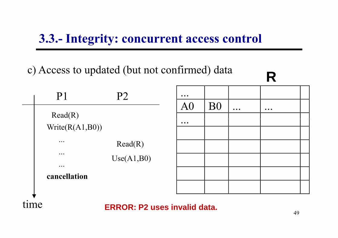
3.3.- Integrity: concurrent access control
c) Access to updated (but not confirmed) data
...
A0 B0 ... ...
...
RP1 P2
Read(R)
49
...
time
Read(R)
Read(R)
Write(R(A1,B0))
...
...
...
cancellation
Use(A1,B0)
ERROR: P2 uses invalid data.

3.3.- Integrity: concurrent access control
Techniques:
• Reserving some data occurrences (locks)
– Examples a) and c) must lock a record.
50
– Examples a) and c) must lock a record.
– Example b) must lock all.
• Need for controlling deadlocks.
• Other solutions (for example c): cascade cancellation or
transaction isolation.

3.3.- Integrity: concurrent access control
Reservation protocols (locks):
• The most common technique to handle concurrent access is
the use of locks. If the reservation protocol is active then:
51
• A piece of information can have three possible states:• Free: nobody can read it, but everybody can lock it.
• Read_lock (or shared reserve): someone has locked it for reading
and can read it. Other users can also lock it for reading. Nobody else
can write it or lock it for writing.
• Write_lock (or exclusive reserve): someone has locked it for writing.
Only this user can read it and write it. Nobody else can lock it.
No user can read or write if the user has not reserved the information previously

3.3.- Integrity: concurrent access control
Reservation protocols (locks):
• The locks must be used conveniently to ensure that
transactions work properly.
52
• A simple way to do this is called 2PL (two phase lock).• All reservations by a transaction are made at the beginning of the
transaction.
• All releases are performed at the end of the transaction.
• This ensures that transactions work properly (in any possible
situation).
• However, this technique can generate deadlock.

3.3.- Integrity: database recovery
The transaction properties of atomicity and persistence
force a DBMS to ensure that:
• If confirmed, the changes performed are recorded in the
database to make them persistent.
53
database to make them persistent.
• If cancelled, the changes performed over the database are
undone.

3.3.- Integrity: database recovery
Causes of transaction failure
• Local to the transaction (normal system operation)
– transaction errors (incorrect database access, failed calculation,
etc.)
54
etc.)
– exceptions (integrity violation, security problems, etc.)
– concurrence control (locked state between two transactions)
– human decisions (inside a program or explicitly).

3.3.- Integrity: database recovery
Causes of transaction failure
• External to the transaction (system error)
– System failures with loss of main memory.
55
– System failures with loss of main memory.
– Failures of the storage system with loss of secondary memory.

3.3.- Integrity: database recovery
Failures of main memory
• In the time period between transaction confirmation and
recording of the fields in secondary memory.
• The transaction is confirmed and its changes are located in
56
• The transaction is confirmed and its changes are located in
blocks in the memory buffers.
• In this time interval, there is a failure with loss of main
memory and the blocks in the buffers are lost.

3.3.- Integrity: database recovery
Failures of secondary memory
• A confirmed transaction whose changes have been
recorded into the database.
57
• Failure in secondary memory and changes are lost.

3.3.- Integrity: database recovery
Recovery from system failures
• Recover confirmed transactions which have not been
recorded.Functions
58
• Cancel transactions which have failed.
• Recovery module.
• Most extended technique: use of log or journal file.

3.3.- Integrity: database recovery
Activities and events recorded in the log file
• Records the update operations performed by the existing
transactions.
59
• The log file is stored in disk to avoid its loss after a system
failure.
• It is dumped periodically into a massive storage unit.

3.3.- Integrity: database recovery
Types of entries which are recorded by the log file
• [start, T]: a transaction has been started with identifier T.
• [write, T, X, value_before, value_after]: the transaction T has
60
performed an update instruction on data X.
• [read, T, X]: the transaction T has read data X.
• [confirm, T]: the transaction T has been confirmed.
• [cancel, T]: the transaction T has been cancelled.

3.3.- Integrity: database recovery
Failure of a transaction T → Undo changes performed by T
• Update the data which has been modified by T with its original
value (value_before).
We assume IMMEDIATE UPDATE
61
value (value_before).
• Search for the entries in the logfile [write, T, X, value_before,
value_after]
System Failure → Apply the previous process to all
unconfirmed transactions

3.3.- Integrity: database recovery
System Failure → • Unconfirmed transactions
[start, T] in the logfile without [confirm, T]
• Previous process
62
→ • Confirmed transactions
[confirm, T]
• Execute them again:
[write, T, X, value_before, value_after ]

3.3.- Integrity: database recovery
PROBLEMS:
• Size of the logfile can increase very quickly.
• Recovery in case of failure is very expensive (many
63
• Recovery in case of failure is very expensive (many
instructions have to be redone).
SOLUTION:
• Checkpoints

3.3.- Integrity: database recovery
Checkpoints →
• Suspend the execution of transactions temporally.
Are recorded in the logfile periodically
64
• Suspend the execution of transactions temporally.
• Record a checkpoint in the logfile.
• Force the recording of all updates of the confirmed
transactions (copy all buffers to disk).
• Resume the execution of the suspended transactions.

3.3.- Integrity: database recovery
checkpoints → recovery from the last checkpoint
T1
time
65
Checkpoint
T2
T4
T5
System Failure
T3
R
A
A
R

3.3.- Integrity: database recovery
Recovery from failures of the storage system
• Loss of secondary memory.
• The database might be damaged totally or partially.
66
• The database might be damaged totally or partially.
• Technique: reconstruction of the database from
– The most recent backup.
– The backup moment, use the logfile to redo all the instructions
performed by the confirmed transactions.

3.3.- Integrity: database recovery
The recovery mechanism is the same (the confirmed ones
In case of DEFERRED UPDATE
67
do not need to be repeated), except from:
• The unconfirmed transactions do not need to be undone.

3.4.- Security
Objective:
The information can only be accessed by the people and
68
The information can only be accessed by the people and
processes that are authorised and in the authorised form.
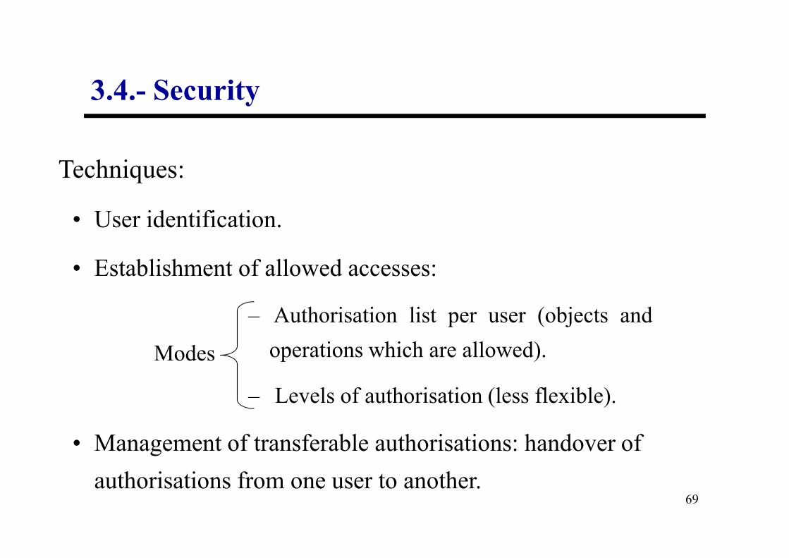
3.4.- Security
Techniques:
• User identification.
• Establishment of allowed accesses:
69
• Establishment of allowed accesses:
– Authorisation list per user (objects and
operations which are allowed).
– Levels of authorisation (less flexible).
• Management of transferable authorisations: handover of
authorisations from one user to another.
Modes

3.4.- Security
• Knowledge of the access authorisations for each user (which
ones are transferable to third users and which are not).
Requirements to perform the management of transferable authorisations:
S Aa
a• Transfer of an authorisation from one user to another (with
70
A Ba
S Aa
Ba
transferable mode or not).
• Later revocation of an access authorisation:
– If granted in transferable mode, revocation
must be done accordingly.
• Independent revocation of an access authorisation
granted in a multiple form.S
AaB
a
Ca a
B must
preserve the
authorisation
‘a’

3.5.- Implementation of relational DB.
Physical (internal) schema:
• Description of the DB in terms of its physical representation
(over secondary storage devices).
71
• The three-level architecture of a DMBS allows us to work with
a database without knowing anything about the implementation
details (independence), but the physical details are important for
the behaviour of the database in terms of response times and
storage space.
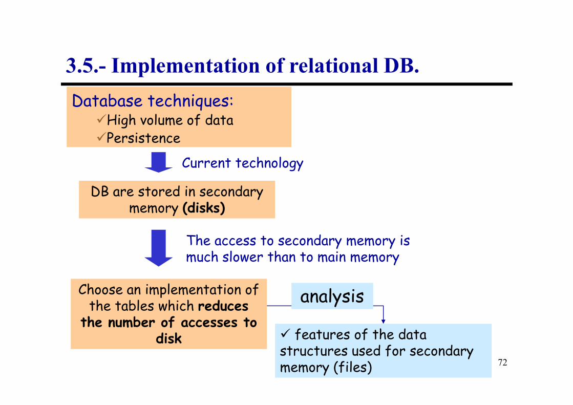
3.5.- Implementation of relational DB.
Database techniques:�High volume of data�Persistence
DB are stored in secondary memory (disks)
Current technology
72
memory (disks)
Choose an implementation of the tables which reduces
the number of accesses to disk
The access to secondary memory is much slower than to main memory
� features of the data structures used for secondary memory (files)
analysis

3.5.- Implementation of relational DB.
Which data structures are frequently used to store data
in secondary memory?
73
datatype “file”

CLASSIFICATION OF FILE ORGANISATIONS
3.5.1.- Basic notions
Access
Structures
74
DISORDERED
ORDERED
HASH
Primary Index
Secondary Index
Hash Function

3.5.2.- Direct Files
• It includes those file organisation models which allow access to
the desired record through its exact location.
• The direct access can be obtained through different methods:
75
– Relative addressing (ordered files)
– Hash
– Use of indexes.

Ordered File with Relative Addressing:
• It is a file in which the records are stored in an ordered way according to the value of one of the fields, so allowing a relative addressing.
• Advantages:
3.5.2.1.- Ordered files
76
• Advantages:
– readings in the order of the sort field are very efficient.
– finding the next record in the order of the ordering field does not require any additional access (except for the last record of a block).
– the search based on the ordering field can be binary over the blocks.

• Drawbacks:
– Access based on a field which is not an ordering field forces a full scan on the file until the record is found.
– Insertion is costly, because we need to locate the place where the record must be inserted, and scroll the subsequent records
3.5.2.1.- Ordered Files
77
the record must be inserted, and scroll the subsequent records down in order to create the gap. Solution → regularly distributed gaps or overflow blocks.
– Deletion is not so troublesome if the record is flagged without (immediately) recovering the space.
– The modification of the ordering field may frequently make the record change its position in the file; this involves a deletion and an insertion.

• The cost of modification of a field different from the ordering field depends only on the search condition of the record we want to modify.
• In order to diminish the great cost for insertion or modification of the value of the ordering field, there are two solutions:
3.5.2.1.- Ordered Files
78
– Use of gaps in the blocks. In this way only one block has to be re-organised. Problems: loss of space and need of periodical re-organisations when the gaps are full.
– Use of a temporal file, known as overflow or transaction, in order to add new records. This overflow file is periodically mixed with the main file with a reorganisation process.
• Direct files with relative addressing (disordered or ordered) are commonly used with indexes.

Hash files:
Characterisation:
• This technique provides a very quick access when the search
condition is made on a value of the hash field, which is
generally a key.
3.5.2.2.- Hash Files
79
generally a key.
• There is a function called hash or randomisation which is
applied to the value of the record’s hash field and returns the
address of the disk block where the record must be.
• To recover most records we need just one access to disk.

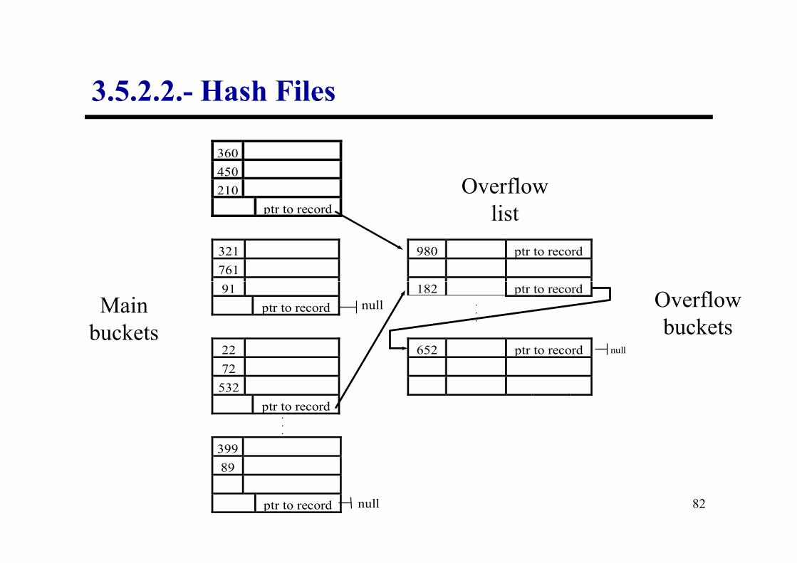
Operation mode:
• The address space which is assigned to the file is composed of
buckets, which can hold several records.
• Let us assume that we have M buckets, whose relative addresses
go from 0 to M–1. We have to choose a function which
3.5.2.2.- Hash Files
80
go from 0 to M–1. We have to choose a function which
transforms the value of a hash field to an integer between 0 and
M–1.
• A common hash function is d(K) = K mod M, which returns the
module of dividing the hash field value K by M.
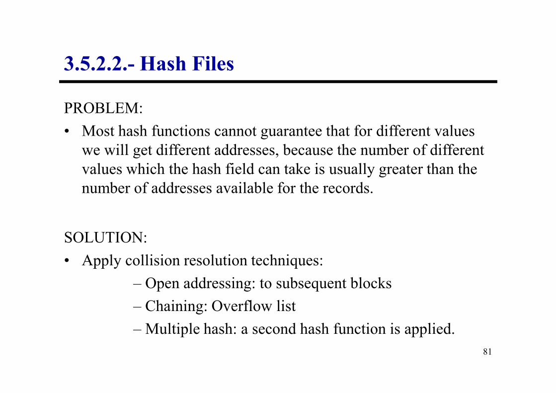
PROBLEM:
• Most hash functions cannot guarantee that for different values
we will get different addresses, because the number of different
values which the hash field can take is usually greater than the
number of addresses available for the records.
3.5.2.2.- Hash Files
81
SOLUTION:
• Apply collision resolution techniques:
– Open addressing: to subsequent blocks
– Chaining: Overflow list
– Multiple hash: a second hash function is applied.
360
450
210
ptr to record
321 980 ptr to record
761
Overflow
list
3.5.2.2.- Hash Files
82
91 182 ptr to record
ptr to record
22 652 ptr to record
72
532
ptr to record
399
89
ptr to record null
null
null
.
.
.
.
.
.
Main
buckets
Overflow
buckets

• Advantages:
– Provides a very quick access to an arbitrary record given by
the hash field value.
3.5.2.2.- Hash Files
83
• Drawbacks:
– It is not very useful if other accesses are performed on the
same file, unless we construct additional accesses.
– The reserved space for the files is fixed (too much space is
lost initially and it becomes overflowed later on).
INDEXES:
• Indexes are access structures which are defined over one or
several indexing fields.
3.5.2.3.- Indexed Files
84
• They consist of an additional file whose records (or entries) are
constructed by two fields: key (indexing field) and address.
• They do not affect the original file.
• A file can have several indexes for several fields.
Indexes provide direct access and ordered access to file records which are not ordered by the indexed field.

3.5.2.3.- Indexed Files
Index
Data file
123 •
85
123
Data file with a sequential or hashed organisation.
Auxiliary structure which provides direct access to the file records

3.5.3.- Choosing the physical schema
• Options which are provided by the DBMS to implement a DB:
– Different types of basic organisations: ordered or unordered, sequential, hash.
86
– Different kinds of hash files: hash function, overflow blocks,...
– Different kinds of indexes.
– Clustering of related tables
– Links through pointers to related records
3.5.3.- Choosing the physical schema
Data definition
File organisation
+
• When defining a schema (with CREATE TABLES) we can
express:
87
Data definition for the table
+
Indexes

• Each DBMS offers a variety of options for file organisation.
• The database designer must have into account:
– Factors of the required response time,
3.5.3.- Choosing the physical schema
88
– Space utilisation for the files and the access structures,
– Frequency of execution of some queries and transactions,
– Other requirements specified for the database.

• The attributes which are meant to be used frequently for
recovering some data must have access paths for them as
primary or secondary indexes.
• Sometimes it is necessary to reorganise some files by
constructing new indexes or changing some methods for
3.5.3.- Choosing the physical schema
89
constructing new indexes or changing some methods for
primary access.
• A very popular option to organise a file in a relational system is
to maintain the file disordered and to create as many secondary
indexes as needed. If all the attributes are indexed, this structure
is called a completely inverted file.

• If the records are meant to be recovered frequently in the order
of one attribute: ordering over that attribute, with the
corresponding primary index, provided the attribute is not
modified too frequently.
• If the file is going to experience too many insertions and
3.5.3.- Choosing the physical schema
90
• If the file is going to experience too many insertions and
deletions, we have to minimise the number of indexes.
• In many systems the index is not an integral part of the file, but
it is created and destroyed dynamically.
• If one file is not going to be used for recovering records in
order, we can use hashing (which can be dynamic if the size of
the file does not vary frequently).

• When two relations have two attributes which are frequently used
to make joins, we can use a physical structure called a relation
cluster.
• A cluster consists of a structure which holds in the same physical
block the tuples of two relations which are usually joined.
3.5.4.- Clusters
91
EXAMPLE:
• Let R1 and R2 be two relations which are joined frequently and
have the following relation schemas:
R1(a1:dom1, a2:dom2)
PK:{a1}
R2(b1:dom3, b2:dom4, b3:dom1)
PK:{b1}
FK:{b3} → R1

EXAMPLE (contd.):
• Data in R1 and R2:
R1 R2
a1 a2
12 Doce
b1 b2 b3
9A ASDF 84
3.5.4.- Clusters
92
12 Doce
51 Cincuenta y uno
84 Ochenta y cuatro
9A ASDF 84
0B QWER 51
1L ZXCV 12
2X QAZ 12
3P POIU 84
4K MNBV 51
5T TTTT 51
6M MMM 12

EXAMPLE (contd.):
• Cluster of R1 and R2:
a1 a2
12 Doce
a1 a2
51 Cincuenta y uno
a1 a2
84 Ochenta y cuatro
BLOCK 1 BLOCK 2 BLOCK 3
3.5.4.- Clusters
93
12 Doce
b1 b2
1L ZXCB
2X QAZ
6M MMM
51 Cincuenta y uno
b1 b2
0B QWER
4K MNBV
5T TTTT
84 Ochenta y cuatro
b1 b2
9A ASDF
3P POIU

ADVANTAGES:
– They reduce the access time for joins.
– Storage saving: the key used for the join is stored only once.
3.5.4.- Clusters
94
DRAWBACKS:
– Clusters reduce the throughput of insertions and updates.

THAT’S ALL
THAT’S ALL
95
ALL FOLKS!ALL
FOLKS!

96