DATABASE CONSISTENCY IN CLOUD DATABASES MD...
218
DATABASE CONSISTENCY IN CLOUD DATABASES by MD ASHFAKUL ISLAM SUSAN VRBSKY, COMMITTEE CHAIR BRANDON DIXON MARCUS BROWN JINGYUAN (ALEX) ZHANG NENAD JUKIC A DISSERTATION Submitted in partial fulfillment of the requirements for the degree of Doctor of Philosophy in the Department of Computer Science in the Graduate School of The University of Alabama TUSCALOOSA, ALABAMA 2013
Transcript of DATABASE CONSISTENCY IN CLOUD DATABASES MD...

DATABASE CONSISTENCY
IN CLOUD DATABASES
by
MD ASHFAKUL ISLAM
SUSAN VRBSKY, COMMITTEE CHAIR
BRANDON DIXON
MARCUS BROWN
JINGYUAN (ALEX) ZHANG
NENAD JUKIC
A DISSERTATION
Submitted in partial fulfillment of the requirements
for the degree of Doctor of Philosophy
in the Department of Computer Science
in the Graduate School of
The University of Alabama
TUSCALOOSA, ALABAMA
2013

Copyright Md Ashfakul Islam 2013
ALL RIGHTS RESERVED

ii
ABSTRACT
Cloud storage service is currently becoming a very popular solution for medium-sized
and startup companies. However, there are still few suitable solutions being offered to deploy
transactional databases in a cloud platform. The maintenance of ACID (Atomicity, Consistency,
Isolation and Durability) properties is the primary obstacle to the implementation of transactional
cloud databases. The main features of cloud computing: scalability, availability and reliability
are achieved by sacrificing consistency. The cost of consistency is one of the key issues in cloud
transactional databases that must be addressed. While different forms of consistent states have
been introduced, they do not address the needs of many database applications.
In this dissertation we propose a tree-based consistency approach, called TBC, that
reduces interdependency among replica servers to minimize the response time of cloud databases
and to maximize the performance of those applications. We compare different techniques of
maintaining consistency, including the classic approach, the quorum approach and our tree-based
consistency approach. We identify the key controlling parameters of consistency maintenance in
cloud databases and study the behavior of the different techniques with respect to those
parameters. Experimental results indicate that our TBC approach reduces interdependency
between data replicas and has good performance.
We also implement a transaction management system using TBC as the consistency
approach. We have designed a hierarchical lock manager that is able to work at a variable

iii
granularity level and allow much more concurrent access to the data items than regular lock
managers. The TBC transaction management system ensures serializability and guarantees the
ACID properties. The common isolation problems in transaction management are prevented, and
we prove that the scenarios of dirty read, unrepeatable read and dirty write or lost update will
never occur in concurrent execution of the transactions. We also present an efficient auto-scaling
feature for the proposed transaction manager. Our experimental results shows that TBC has
better response time than other approaches regardless of the arrival rate, read-write ratio,
variation in data selection preference or database size. The Tree-Based Consistency approach is a
viable solution for ACID transactional database management in a cloud.

iv
DEDICATION
I would love to dedicate this thesis to my wife and my mom and dad who always stay on
my side in every hurdles I ever faced in my life.

v
LIST OF ABBREVIATIONS
2PC Two Phase Commit
ACID Atomicity, Consistency, Isolation and Durability
CAP Consistency, Availability, Partition
CRM Customer Relationship Management
DaaS Database as a Service
DBMS DataBase Management System
DC Data Component
DFS Distributed File System
ElasTraS Elastic Transactional System
HTM Higher Level Transaction Manager
IaaS Infrastructure as a Service
IT Information Technology
LogBase Log-Structured Database
LTMs Local Transaction Managers
MM Metadata Manager
MTBC Modified Tree Based Consistency
OLTP On-Line Transaction Processing
OTM Owning Transaction Manager

vi
PaaS Platform as a Service
PEM Performance Evaluation Metric
PF Performance Factor
QoS Quality of Services
RDS Relational Database Services
S3 Simple Storage Service
SaaS Software as a Service
SLAs Service Level Agreements
TaaS Transactions as a Service
TBC Tree Based Consistency
TC Transactional Component
TM Transaction Manager
TPS Transaction Processing System
WA Workload Analyzer
WF Weight Factor

vii
ACKNOWLEDGMENTS
I would like to express my deepest appreciation and gratitude to my professor and advisor
Dr. Susan Vrbsky. Without her guidance, support, and assistance it would not be possible for me
to finish my PhD research. She literally taught to me how to do mature research, how to face
problems, organize thoughts, find out solutions and implement them in real settings, conduct
experiments, analyze the results and show them in publications. It was tough to survive in a
different world with a new culture, new language, and new people. She was always there for me
to face all these problems as a mentor, colleague, friend and family.
I am pleased to have this opportunity to thank all of my committee members. Dr.
Brandon Dixon helped me to learn, understand and build a strong base on algorithms. I got the
basic idea of the core algorithm of my research work from his class. Dr. Marcus Brown helped
me to organize my thoughts and express them in my dissertation. I served as his teaching
assistant for my last year. His friendly advice encouraged me to complete this job. Dr. Alex
Zhang helped me to do a better analysis of the results of my research work. Dr. Nenad Jukic gave
me excellent suggestions for my research work.
My sincerest gratitude and appreciation goes to my lovely wife Subrina Rahman who
constantly supported me in this dissertation writing. She gave me the best support and comfort to
finish the report. I would like to mention my mom, dad, brother and sisters too. Without their
support I would not be able to finish my dissertation.

viii
I would like to thank all of my lab members: Dr. Michael Galloway, Kazi Zunnurhain,
Gabriel Loewen, Jeffery Robinson, Calvin Vreeland, Karl Smith, and Rob Carr for giving me
excellent suggestions for my research work, and helping to find and solve my problems. Without
your great and enjoyable company, it was not possible for me to pass the long journey here.
I would like to say thanks to my friends in the department of Computer Science, Dr.
Mohammad Asadul Hoque who encouraged me to choose the University of Alabama to pursue
my PhD, Dr. Ferosh Jacob who encouraged me in my research and dissertation writing, and
Amiangshu Bosu and Debarshi Chatterji who helped me to solve different technical problems.
I want to mention a few more names, Dr. Muhammad Sharif, Dr. Anwarul Haque, Dr.
Mohammad Shamsuzzoha, Dr. Jewel Hasan, Dr. Akand Islam, Dr. Rezwan Rahman, Taofiq
Ezaz, Didrul Bhuiya, Dr. Faisal Hashmee, Raina Hasan, Ashirul Mubin, and Najim Hasan who
helped me to enjoy the life in Tuscaloosa.
Finally, I would like to thank the Department of Computer Science in the University of
Alabama for providing the financial support to continue my PhD.

ix
CONTENTS
ABSTRACT ................................................................................................ ii
DEDICATION ........................................................................................... iv
LIST OF ABBREVIATIONS .....................................................................v
ACKNOWLEDGMENTS ........................................................................ vii
LIST OF TABLES ................................................................................... xiii
LIST OF FIGURES ................................................................................. xiv
LIST OF ALGORITHMS ........................................................................ xvi
LIST OF EQUATIONS ......................................................................... xvii
1. INTRODUCTION ...................................................................................1
2. RELATED WORK ..................................................................................8
2.1. Databases Management in Clouds ......................................................11
2.2. Types of Data Consistency .................................................................14
2.3. Transactions in Cloud Databases ........................................................18
2.4. Examples of Commercial Cloud Databases ........................................23
3. TREE BASED CONSISTENCY (TBC) ...............................................25
3.1. System Description .............................................................................27
3.2. Performance factors ............................................................................28
3.3. Building the Tree ................................................................................31
3.4. Update Operation ................................................................................35

x
3.5. Maintaining Consistency ....................................................................37
3.6. Auto Scale Up .....................................................................................38
3.7. Number of Maximum Allowable Children .........................................38
3.8. Inconsistency Window ........................................................................40
3.9. Failure Recovery .................................................................................42
3.10. Apparent Consistency .......................................................................44
4. PERFORMANCE ANALYSIS .............................................................45
4.1. Classic Approach ................................................................................45
4.2. Quorum Approach ..............................................................................46
4.3. Tree-Based Approach .........................................................................47
4.4. Experimental Environment .................................................................48
4.5. Experiment Design..............................................................................49
4.6. System Load Calculation ....................................................................51
4.7. Effect of Database Request Rate.........................................................54
4.8. Effect of Read/Write Request Ratio ...................................................56
4.9. Effect of Network Quality ..................................................................58
4.10. Effect of Heterogeneity .....................................................................61
5. TRANSACTION MANAGEMENT IN TBC .......................................63
5.1. Transactions ........................................................................................64
5.2. Serializability ......................................................................................65
5.3. Concurrency Control ...........................................................................67
5.4. Transaction Management in TBC .......................................................70
5.4.1. Read-Write Transactions in TBC.....................................................70
xi
5.4.2. Read-Only Transactions in TBC ......................................................74
5.5. The Lock Manager in TBC .................................................................76
5.6. Concurrency Control in TBC ..............................................................80
5.7. Serializability in TBC .........................................................................81
5.8. Common Isolation Level Problems ....................................................84
5.9. Preserving the ACID properties ..........................................................86
6. PERFORMANCE ANALYSIS OF THE TRANSACTION
MANAGEMENT SYSTEM .................................................................89
6.1. Transaction Manager for Different Consistency Approaches ............90
6.1.1. Transaction Execution in the Classic Approach ..............................91
6.1.2. Transaction Execution in the Quorum Approach ............................93
6.1.3. Transaction Execution in TBC.........................................................93
6.2. Experiment Environment ....................................................................94
6.3. Experiment Design..............................................................................95
6.4. Effect of the Transaction Request Rate ..............................................98
6.5. Effect of the Read-Only/Read-Write Transaction Request Ratio .....102
6.6. Effect of the Selection Skewness Parameter .....................................107
6.7. Effect of Number of Tables and Columns ........................................110
7. AUTO SCALING AND PARTITIONING ........................................115
7.1. Auto Scaling......................................................................................115
7.2. Partitioning .......................................................................................116
7.3. Auto Scaling in TBC .........................................................................118
7.3.1. Auto Scaling for Read-Only Transactions .....................................119
7.3.2. Auto Scaling for Read-Write Transactions ....................................121

xii
7.4. Database Partitioning in TBC ...........................................................124
7.5. Future Work in Auto Scaling ............................................................125
8. CONCLUSION ....................................................................................128
REFERENCES ........................................................................................131
APPENDIX ..............................................................................................140

xiii
LIST OF TABLES
Table 1: Default Parameters......................................................................................50
Table 2: Read/Write Times (CPU + Disk) ...............................................................53
Table 3: Default Parameters in Transaction Execution ............................................98

xiv
LIST OF FIGURES
Figure 1: Hybrid Cloud ...................................................................................9
Figure 2: Communication between Controller and Replicas ........................28
Figure 3: Example of a Tree Calculation ......................................................32
Figure 4: Effect of Sparse and Dense Trees on the TBC Approach .............40
Figure 5: Inconsistency Window ..................................................................42
Figure 6: Write and Read Techniques of the Classic Approach ...................46
Figure 7: Write and Read Techniques of the Quorum Approach .................47
Figure 8: Write and Read Techniques of the TBC Approach .......................48
Figure 9: Effect of Database Request Rate ...................................................55
Figure 10: Effect of Read/Write Ratio ..........................................................57
Figure 11: Effect of Network Quality ...........................................................60
Figure 12: Effect of Heterogeneity ...............................................................62
Figure 13: State Diagram of a Transaction ...................................................65
Figure 14: Read-Write Transaction Execution in TBC ................................72
Figure 15: Read-Only Transaction Execution in TBC .................................74
Figure 16: Hierarchical Lock Manager .........................................................78
Figure 17: Layered Architecture of Transaction Management System ........91
Figure 18: Transaction Execution in the Classic Approach ..........................92

xv
Figure 19: Transaction Execution in the Quorum Approach ........................94
Figure 20: Transaction Execution in TBC Approach ...................................95
Figure 21: Effect of Transaction Request Rate ...........................................100
Figure 22: Effect of Read-Only/Read-Write Transaction Request Ratio ...106
Figure 23: Effect of the Selection Skewness Parameter .............................109
Figure 24: Effect of Number of Tables and Columns .................................112
Figure 25: Auto Scaling (Read-Only Transaction) .....................................120
Figure 26: Auto-Scaling (Read-Write Transaction) ...................................122
Figure 27: A Possible Partition Tree ...........................................................124

xvi
LIST OF ALGORITHMS
Algorithm 1: Modified Dijkstra .................................................................33
Algorithm 2: Initialization .........................................................................33
Algorithm 3: Find Max ..............................................................................34
Algorithm 4: Reweight ..............................................................................34
Algorithm 5: Relax ....................................................................................34

xvii
LIST OF EQUATIONS
Equation 1: PEM Calculation ....................................................................31
Equation 2: Primary Server Load in Classic ..............................................52
Equation 3: Secondary Server Load in Classic ..........................................52
Equation 4: Primary Server Load in Quorum ............................................52
Equation 5: Secondary Server Load in Quorum ........................................52
Equation 6: Primary Server Load in TBC ..................................................52
Equation 7: Secondary Server Load in TBC..............................................52

1
CHAPTER 1
INTRODUCTION
The importance and popularity of the cloud computing concept is increasing every day.
Cloud computing has transitioned from a buzzword in information technology (IT) and the
research community, into one of the most promising aspects of the IT industry. The most highly
touted characteristics of the cloud computing platform are its on-demand provisioning to
computing resources, pay-per-use model, infinite elasticity, ubiquitous access, high availability
and reliability. The economic model provided by the cloud computing platform is also an
important reason behind its popularity. Cloud infrastructure is built by a large number of
moderate strength computing servers, and maintenance costs of these servers is low compared to
any supercomputer.
It can be argued that this is the second coming of cloud computing. [1, 2] About 50 years
ago, service bureaus and time-sharing systems were created to provide on-demand access to
computing machinery for users who were not able to maintain mainframe computers. A typical
time-sharing service had a hub-and-spoke configuration, as individual users at terminals
communicated over telephone lines with a central site, where all the computing was done. In the
early 80s, personal computers arrived and users were free to control their own computing
environment, choosing software according to their needs and customizing systems to their tastes.
The advent of the networked era allowed every computer to reach distant data centers,
communicate with many servers and at the same time exchange information through the Internet.

2
Interconnected computers were even able to share data and computational power among
themselves to solve problems. As a result, IT personnel and entrepreneurs began to rethink
mainframe computing, allowing for the development of the idea of third party computing
resource providers in the form of clouds.
Cloud computing shares the basic theme of previous paradigms associated with the
provisioning of computing infrastructure. However, cloud computing differs in that it shifts the
location of the infrastructure to the network to provide basic components. These basic
components, such as storage, CPUs, and network bandwidth, are provided as a service by
specialized service providers at a low unit cost. Users of these services are guaranteed not to be
worried about scalability and backups because the available resources are virtually infinite and
failed components are replaced without any service interruption and data loss [35, 64].
From the user’s point of view, cloud computing stands for the ability to rent several
servers or several thousand servers and run distributed applications on those servers. It is also
the ability to rent a virtual server, load software on it and turn it on and off at will like a desktop.
It can be the ability to store and secure infinite amounts of data. It is also the ability to use a
vendor supported platform including OS, Apache, MySQL, Perl, Python and PHP, and the ability
to adjust to changing workloads [5]. From a service provider’s point of view, cloud computing
stands for passing the cost of deployment, administration, operation and maintenance to the end
user, in terms of storage, computing and network bandwidth usage [6, 14, 32].
All data applications today need to be highly available and support ubiquitous
accessibility [30, 31, 33, 34, 37]. A single moment of an application outage can cause a very
large amount of revenue loss and leave a bad impression on the business reputation of that
organization. The amount of on-premises data is also increasing exponentially. Infrastructure

3
deployment is nearly impossible for small and startup companies [20]. Moreover, promotions,
sales, holidays and special occasions in a consumer market can create an enormous spike in the
workload of data applications. Deployment of available resources to handle that spike could be
the wrong strategic decision for any company, because the rest of the year those resources are
unused. As a result, the following key difficulties are usually faced in managing data applications
[4]. First, it is difficult to acquire the amount of resources required for large-scale data in
traditional data processing. Second, it is difficult to get any amount of on-demand resources.
Third, it is difficult to distribute and coordinate a large scale job on several servers and provision
another server for recovery in case of server failure. Fourth, it is difficult to auto scale-up and
down based on dynamic workloads. Fifth, it is difficult to remove of all those resources when the
job is done.
Cloud architectures can solve some of the key difficulties faced in large-scale data
processing [4, 15, 71]. However, there are many questions which are raised and must be
answered before the deployment of data management in a cloud computing platform can be a
viable solution for users. First of all, the structure of a data management application must be
determined, such as whether it is centralized or distributed. A major portion of cloud customers
are small startup companies, so a centralized application can be a good solution for them.
Obviously, a cloud platform will be able to auto scale-up the seasonal spike load of these
companies. But some researchers have discerned there are settings when the structure of a
database should be distributed. Abadi et al.[7] showed if the data size is less than 1 TB, then a
centralized data management application is more suitable than a distributed data management
application. The overhead of distributed computing plays an important role in this case,
particularly for transactional databases.

4
Transactional data management is the heart of the database industry. A transaction is a
logical unit of works, that consists of a series of read and/or write operations to the database.
Nowadays, almost all business transactions are conducted through transactional data
management applications. These applications typically rely on guaranteeing the ACID
(Atomicity, Consistency, Isolation and Durability) properties provided by a database and they are
fairly write-intensive. Performing a write operation could be time consuming due to ACID
property maintenance, especially for a system distributed over different geographic locations like
a cloud [42, 51, 54]. Analytical data management systems can tolerate such time delays, but for
transactional data management systems, such time delays are quite unacceptable. That is why
many existing solutions for cloud databases are applicable only to analytical databases [9].
Analytical databases are designed for business intelligence and decision support systems. They
typically contain historical data that is read only, and as such do not need strong guarantees
about the ACID properties. Therefore, one of the main challenges is to deploy transactional data
management applications on cloud computing platforms that maintain the ACID properties
without compromising the main features of cloud platform like scalability and availability [60,
61, 62].
A consistent database must remain consistent after the execution of each and every
transaction. Any kind of inconsistent state of the data can lead to significant damage, which is
completely unacceptable. Service availability and data reliability are usually achieved by
creating a certain number of replicas of the data distributed over different geographical areas [7,
68]. Amazon’s S3 cloud storage service replicates data across ‘regions’ and ‘availability’ zones
so that data and applications can persist even in an entire location black out. Maintaining
consistency in such a distributed platform is time consuming and could be expensive in terms of

5
performance. That is why most of the time consistency is sacrificed to maintain high availability
and scalability in the implementation of transactional applications in cloud platforms.
Some techniques tradeoff between the consistency and response times of a write request.
The authors in [8, 11, 12] develop models for transactional databases with eventual consistency,
in which an updated data item becomes consistent eventually. Other approaches [10, 43] use data
versioning to keep a reasonable amount of delay. However, data versioning and compromised
consistency are not favorable for transactional databases. Some market available cloud-based
databases [38, 44] use the quorum-based protocol to maintain consistency, while other cloud-
based relational database solutions [45] use pull-based consistency techniques.
Serializability and concurrency control are major issues in the execution of a transaction
in any computing platform [41]. Concurrency control ensures that when database transactions are
executed concurrently, the results of the transactions are consistent and serializable, meaning
they are the same as if they were executed serially. Consistency maintenance becomes more
complex by allowing concurrent access to a database, especially in a distributed platform like a
cloud platform [42]. Several strategies have been proposed to implement a transaction manager
in a cloud platform, but each has their limitations. The strategies in [11,12] divide the transaction
manager into multiple levels to perform both distributed and local affairs in transaction execution
in a cloud platform. Specifically, the strategy in [11] is designed for web-based transactions, but
data can become unavailable during failures, while the proposed strategy in [12] can support
only a subset of database operations. For the strategy in [65], transactional logs are stored in a
file instead of executed on the actual database, but this strategy is applicable to applications that
have only a few updates to the data.

6
Auto-scaling is one of the advantages provided by a cloud computing platform [72, 73].
Each and every application deployed on a cloud platform should be able to take advantage of this
feature. Decisions for scaling-up or scaling-down have a significant impact on performance and
resource usage, because there is an overhead associated with the auto-scaling process. It is very
important to distinguish between the actual change in the workload and an anomaly. Different
ideas are proposed in [21, 58, 59, 67, 70] to predict workloads in advance. Using such strategies
can help the system to prepare in advance when to scale-up or scale-down.
In this dissertation we propose a new consistency approach for cloud databases, named
Tree-Based Consistency (TBC), which maximizes performance and maintains consistency in an
efficient manner. We begin by identifying the various factors that affect the performance in our
system and we discuss how these factors are utilized to build a consistency tree. We describe the
steps needed to process a database read or write request using the TBC approach. We analyze the
performance of the TBC approach and compare it to several existing approaches. We also
propose a new type of consistency associated with TBC, called apparent consistency.
The next step is to consider TBC in a transactional environment and we present the
transaction management feature in the TBC system. A hierarchical lock manager is implemented
to manage the concurrency control in TBC. We prove that serializability is ensured within the
TBC system and common isolation errors are also addressed. We analyze the performance of the
proposed transaction management system and compare TBC to existing approaches. Lastly, we
include auto-scaling features in the TBC system in order to support the elastic nature of a cloud.
A database partitioning process is presented that supports the auto-scaling process. Future work
for this dissertation is identified, that includes smart partitioning in the TBC system.

7
In Chapter 2 we describe related work for databases in clouds. In Chapter 3 we present
our TBC approach for cloud databases and in Chapter 4 we present the performance analysis of
our TBC approach. In Chapter 5 we present the transaction manager and the lock manager for
the TBC approach, and in Chapter 6 we analyze the performance of the proposed transaction
manager. In Chapter 7 we discuss auto-scaling and partitioning issues using the TBC approach.
Conclusions are presented in Chapter 8.

8
CHAPTER 2
RELATED WORK
Luis et al. [3] analyze 24 different cloud definitions given by different experts from
different points of view. Some experts emphasize the immediate scalability and resource usage
optimization as key elements for the cloud. Some researchers focus on the business model (pay-
as-you-go) and the reduced infrastructure cost in terms of utility computing. Others concentrate
on Service-Level Agreements (SLAs) between the service provider and the consumers to reach a
commercial mainstream and to maintain a certain Quality of Service (QoS). Some experts define
a cloud as a collection of data centers which are able to provide great amounts of computing
power and storage by using standby resources. According to some researchers, virtualization
plays an important role in clouds. Other experts want to define the cloud with a variety of
aspects, such as deployment, load balancing, provisioning, and data and processing outsourcing.
Taking all these features into account, the authors in [3] provide an encompassing definition of
the cloud. “Clouds are a large pool of easily usable and accessible virtualized resources. These
resources can be dynamically reconfigured to adjust to a variable load (scale), allowing also for
an optimum resource utilization.”
There are many aspects to consider that offer complementary benefits when making the
decision to use a cloud [76, 77, 79]. For example, there are three basic service models to consider
[5]: public clouds, private clouds and hybrid clouds. Public clouds are run by third parties and
applications from different customers are likely to be mixed together on the cloud’s servers,

9
storage systems, and networks. Public clouds are most often hosted away from the customer’s
location. Public clouds provide a way to reduce customer risk and cost by providing a flexible,
temporary extension to enterprise infrastructure. Private clouds are built for one client to provide
maximum control over data, security and quality of service. The company owns the
infrastructure and has control over how applications are deployed on it. Private clouds may be
deployed in an enterprise datacenter or co-location facility.
As shown in Figure 1 [5], hybrid clouds are a combination of public and private cloud
models. The ability to expand a private cloud with the resources of a public cloud can be used to
maintain service levels in an environment with rapid workload fluctuations. This is most often
seen with the use of storage clouds to support Web 2.0 applications.
Figure 1: Hybrid Cloud
Cloud computing can describe services being provided at any of the traditional layers
from hardware to applications. Usually cloud service providers tend to offer services that can be
grouped into three categories [2, 5, 24, 83, 88]: infrastructure as a service (IaaS), platform as a
service (PaaS) and software as a service (SaaS). Infrastructure as a service delivers basic storage
and compute capabilities as standardized services over the network. Servers, storage systems,
10
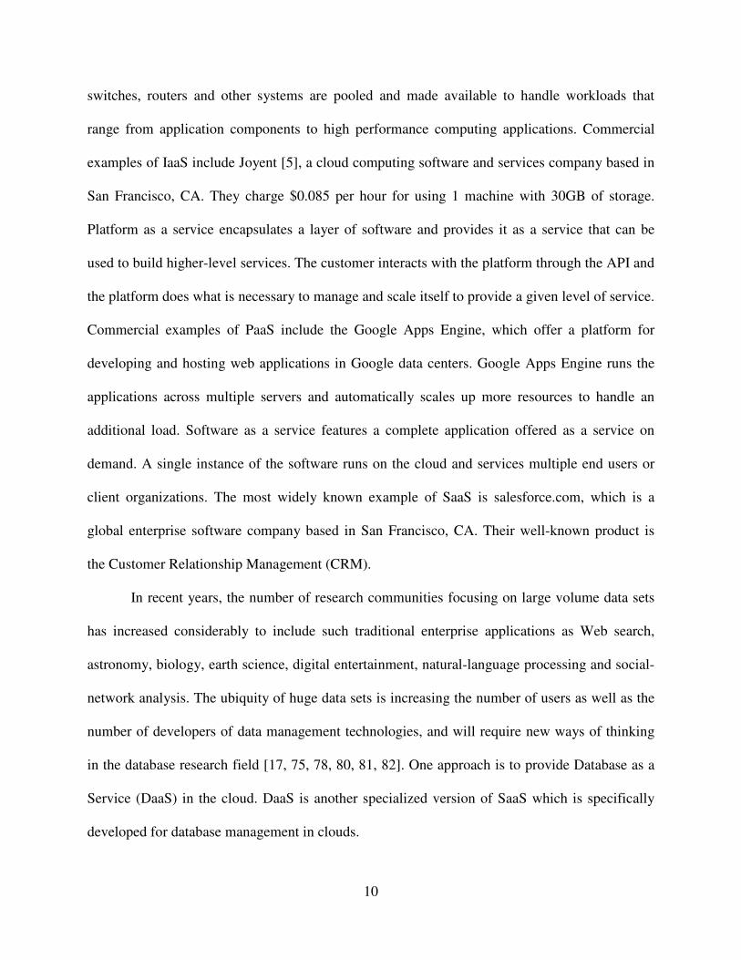
switches, routers and other systems are pooled and made available to handle workloads that
range from application components to high performance computing applications. Commercial
examples of IaaS include Joyent [5], a cloud computing software and services company based in
San Francisco, CA. They charge $0.085 per hour for using 1 machine with 30GB of storage.
Platform as a service encapsulates a layer of software and provides it as a service that can be
used to build higher-level services. The customer interacts with the platform through the API and
the platform does what is necessary to manage and scale itself to provide a given level of service.
Commercial examples of PaaS include the Google Apps Engine, which offer a platform for
developing and hosting web applications in Google data centers. Google Apps Engine runs the
applications across multiple servers and automatically scales up more resources to handle an
additional load. Software as a service features a complete application offered as a service on
demand. A single instance of the software runs on the cloud and services multiple end users or
client organizations. The most widely known example of SaaS is salesforce.com, which is a
global enterprise software company based in San Francisco, CA. Their well-known product is
the Customer Relationship Management (CRM).
In recent years, the number of research communities focusing on large volume data sets
has increased considerably to include such traditional enterprise applications as Web search,
astronomy, biology, earth science, digital entertainment, natural-language processing and social-
network analysis. The ubiquity of huge data sets is increasing the number of users as well as the
number of developers of data management technologies, and will require new ways of thinking
in the database research field [17, 75, 78, 80, 81, 82]. One approach is to provide Database as a
Service (DaaS) in the cloud. DaaS is another specialized version of SaaS which is specifically
developed for database management in clouds.

11
2.1 Databases Management in Clouds
Some advantages and disadvantages of deploying database systems in the cloud are
presented in [7, 94, 97]. The authors mainly considered typical properties of commercially
available database management applications. They examined whether these properties are well
suited to cloud computing platforms. They identify three main characteristics of cloud platforms
as an evaluation metric for databases. The criteria are: the elastic nature of cloud resources, data
security in clouds and data replication in clouds.
An application cannot take advantage of an elasticity of computational power unless the
workload is parallelizable. Cloud computing platforms [22, 23, 96] can adjust to any amount of
workload within seconds. An application should be able to distribute its workload to available
computational resources. When the workload increases, the application should be able to offload
current resources and assign those jobs to newly added resources. When the workload decreases,
the application should be able to free some resources and assign those jobs to other unsaturated
resources.
In a cloud platform, it is possible that data could be stored at an untrusted host, at any
geographical location across the globe. Moving data off the premises and storing it in a third
party vendor’s servers potentiality increases the security risks. Even different countries have
different rules and regulations. Any government can force access to data stored in that country by
law. In that case, data is handed over without any notification to the owner of the data. Encrypted
SQL [28] can be a good solution for this problem.
Data is replicated in a cloud, and often across large geographic distances. To maintain
data availability and durability, data needs to be replicated in different locations. Most of the

12
cloud computing vendors often maintain a number of data centers around the world to provide a
high level of fault tolerance.
Many researchers [7, 25] assert that clouds are best suited for analytical data management
applications. Analytical data management is much different from transactional data management.
Usually, analytical data applications are used for business planning, problem solving, and
decision support. This type of application handles historical data from multiple operational
databases, which requires little or no updates. The analytical data applications of Teradata,
Netezza, Green-plum, DATAllegro (recently acquired by Microsoft), Vertica, and Aster Data are
currently available commercial analytical data applications that are able to run on a shared-
nothing architecture like a cloud platform. The ever-increasing size of analytical data forces
analytical applications to run on an elastic architecture. Many analytical tasks require sensitive
data, and much damage can occur if sensitive data is handed to any business rival. The potential
risk of sensitive and private data leakage still persists for analytical data management
deployment in a cloud platform. As analytical data management deals with historical data, a
recent snapshot of a database can be enough for analytical purposes. As mentioned before,
analytical data does not typically require updates, so even when data is replicated, data will
always be consistent. Therefore, a compromise in consistency is not an important issue for
analytical applications.
Nowadays, almost all business transactions are conducted through transactional data
management applications. A transaction can be defined as a set of read and write operations to be
executed atomically on a single consistent view of a database. Given the large volume of
transactional databases, it seems imperative for cloud systems to accommodate these applications
[84, 87, 89, 92]. Transactional data management applications can be fairly write-intensive and

13
typically rely on the ACID guarantees of Atomicity, Consistency, Isolation and Durability
provided by a database. Atomicity means either all of the operations of a transaction are
completed successfully or all of them discarded. Consistency means a consistent database
remains consistent after execution of every transaction. Isolation means the impact of a
transaction on a data item cannot be altered by another transaction’s access on the same data
item. Durability means the impact of a committed transaction would not be undone in case of a
database failure.
The ACID properties imply serializability, which means that if multiple transactions are
executed, the results are the same as if each transaction executed serially. The main challenge to
deploy transactional data management applications on cloud computing platforms is to maintain
the ACID properties without compromising the main feature of cloud platform scalability. If a
transactional database is implemented on an elastic architecture such as a cloud, data is
partitioned across sites, so a transaction cannot be restricted to accessing data from a single site.
ACID property maintenance becomes harder and more complex in such distributed systems.
Different strategies [8, 11, 12, 26, 29] have been proposed to maintain ACID properties
in a cloud. For example, Atomicity can be implemented by the two-phase commit protocol; the
eventual consistency model could be a solution for Consistency; a multi-version concurrency
control or global timestamp can be used to implement Isolation; and Durability can be
implemented with a global queuing system. Consistency still remains an unresolved issue in the
implementation of transactional databases in a cloud, because the eventual consistency model is
not a suitable solution for most transactional databases.

14
2.2 Types of Data Consistency
The first consistency model for traditional databases was given in 1979 [18]. It lays out
the fundamental principle of database replication and a number of techniques to achieve
consistency. Most of the techniques try to achieve consistency by maintaining distribution
transparency, which means any replication appears as only one database to the users instead of
an interconnected replicated database. Hence, a data value is not returned until all replica copies
can return the same value.
In the network era, databases have become highly distributed and replicated over a
network. As a result, consistency maintenance becomes harder. Eric Brewer proposed the CAP
theorem [16, 46], which states that at most two out of three properties of a database: data
Consistency, data Availability, and data Partitions can be achievable at a time. In a cloud
platform, data is usually replicated over a wide area to increase reliability and availability. As a
result, only the ’C’ (consistency) part of ACID remains to be compromised.
However, a consistent database must remain consistent after the execution of a sequence
of write operations to the database. Any kind of inconsistent state of the data can lead to
significant damage, especially in financial applications and inventory management, which is
unacceptable. Most of the time consistency is sacrificed to maintain high availability and
scalability in the implementation of transactional applications in cloud platforms [47, 48, 49, 50].
To maintain strong consistency in such an application is very costly in terms of performance.
To solve consistency issues in a cloud platform, the eventual consistency model is
presented in [13]. This model presents different types of consistency. The typical consistency is
introduced as strong consistency, in which after an update operation all subsequent accesses will
return the updated value. The model also introduces weak consistency in which subsequent

15
accesses to a database may or may not return the updated value. The main focus of this model is
a specific form of weak consistency, called eventual consistency. In eventual consistency, all
subsequent accesses to a data will “eventually” return the last updated value if no additional
updates are made to that data object.
Vogels et al. [13] uses the notation: N = the number of replicas servers, W = the number
of replica servers who are acknowledged before the completion of a write (update) operation,
and R = the number of replica servers who communicate for a read operation. If W+R > N, then
the write set and the read set always overlap and the system can guarantee strong consistency.
But if R+W<=N, then consistency cannot be guaranteed and weak or eventual consistency arises.
To ensure a fast read operation with strong consistency, usually R=1 and W=N are used. For a
fast write operation with strong consistency, W=1 and R=N are used. Eventual consistency is
adopted by many data management solutions in clouds.
A number of variations of eventual consistency are proposed as an alternative to strong
consistency, including casual consistency, read-your-writes consistency, session consistency,
monotonic-read consistency and monotonic-write consistency. Strong Consistency is defined as:
after each update operation, any subsequent access will reflect the updated value. If subsequent
accesses to the data do not reflect the most recent update operation, then the system is weakly
consistent. However, the system has to meet some conditions before the updated value will be
returned, even if it is weakly consistent. Eventual Consistency is defined as: the storage system
guarantees that eventually all accesses will return the last updated value if no new updates are
made. The maximum size of the inconsistency window can be calculated from factors like
communication delays, workload of the system and number of replicas of the system. Causal
Consistency is defined as: if process A informs process B about an update operation, a

16
subsequent read operation by process B will reflect the update operation by process A. Normal
eventual consistency rules will be applied for all subsequent accesses by Process C. Read-Your-
Writes Consistency is defined as: all subsequent read operations of Process A will reflect the
most recent update operation done by Process A. This is a special case of the causal consistency
model. Session Consistency for any process means, the system guarantees read-your-writes
consistency during a session created by that process. If the session terminates due to any kind of
failure, a new session must be created. Monotonic Read Consistency means if a process accesses
a particular version of the data, then all subsequent accesses will never return an older version of
that data. For Monotonic Write Consistency, the system guarantees to serialize the writes by the
same process.
The authors in [10] propose a new paradigm for transactional databases named
Consistency Rationing, in which the degree of consistency for a data item may differ by trading-
off between cost, consistency and availability of that data item. A higher level of consistency
indicates a high cost per transaction and reduced availability. A lower level of consistency
indicates a low cost per transaction and higher availability, but it might result in a higher penalty
for inconsistency. All data need not be treated at the same level of consistency. For example,
credit card and account balance information require higher consistency levels than user
preferences in a Web shop data management application. This distinction is important because
maintaining a higher consistency level increases actual cost per operation. Similarly, the price of
inconsistency can be measured by mapping the percentage of incorrect operations for lower level
consistency to an exact cost in monetary terms.
A dynamic consistency strategy is proposed in [10] to reduce the consistency level when
the penalty cost is low and raise the consistency level when the penalty cost is high. All data are

17
divided into three categories (A, B, and C) and treated differently depending on the consistency
level requirement. The A category encompasses data with large penalty costs for consistency
violations. The C category covers the data which tolerates temporal inconsistency with no or low
penalty cost. The B category contains all the data with variable consistency requirements over
time. A significant trade off can be made between cost per operation and consistency level for
this B category. The C category data guarantees session consistency. The system guarantees
read-your-own-writes monotonicity during the session. Consecutive sessions may not
immediately see the writes of its previous session. Sessions of different clients will not always
see each other’s updates. However, the system converges and becomes consistent after some
time.
Data in category A always stays in a consistent state and all update operations to this
category data are serializable. (Serializability means even if the update operations from multiple
transactions are interleaved, the database state is the same as if the transactions were executed in
some serial order). Ensuring serializability in cloud storage is expensive in terms of performance,
as a more complex protocol is needed to ensure serializability in a highly distributed
environment. There exists a wide spectrum of data types between data with session consistency
and data with serializability whose level of consistency requirement depends on the concrete
situation. Data of the B category switches between session consistency and serializability at
runtime. It is possible that different transactions operate at different levels of consistency for the
same B data record. A single transaction can processes data from different categories. Every
record affected in a transaction is handled according to their category guarantees. The result of
joins, unions and any other operations between different categories do not cause any harm most
of the time. For example, a join between account balances (A data) and customer profiles (C

18
data) will contain all up-to-date balance information but might contain old customer addresses.
However, this is not a viable solution when consistent and up-to-date data is needed.
2.3 Transactions in Cloud Databases
A transaction consists of a number of read and/or write operations to be executed on a
database by maintaining ACID properties. In order to implement a transactional database system,
a transaction management system needs to be deployed in the cloud platform like other data
applications. There are several challenges to implementing a transaction manager in a cloud
platform. The most important challenge is to maintain the ACID properties in transaction
management. A variety of solutions have been proposed to meet the challenges.
Wei et al. [11] propose to split the cloud transaction manager into several Local
Transaction Managers (LTMs) and distribute the data and load of transactional applications
across LTMs. They have taken advantage of two important properties typical of Web
applications in designing an efficient and scalable system. First, all transactions of typical web
applications are short-lived because each transaction is encapsulated within a particular user
request processing. Supporting long-lived transactions in scalable transactional systems is very
difficult to design. Second, the data request of web applications can be responded to with a small
set of well-identified data items. This implies a low number of conflicts between multiple
transactions trying concurrently to read or write the same data items. Data items and transaction
states are replicated to multiple LTMs. As mentioned previously, typical cloud services explicitly
choose high availability over strong consistency. However, transactional consistency if provided
for the applications at the cost of unavailability during network failures.
A Transaction Processing System (TPS) is composed of several LTMs which are
responsible for a subset of all data items. The Web application chooses one of the LTMs with at

19
least one of the required data items for a transaction. This LTM coordinates across all LTMs
with data items accessed by the transaction. The LTMs operate on a local copy of the data items
copied from the cloud. Resulting data updates are done on the local copy of the LTMs and
periodically checkpointed back to the cloud storage service. The two-phase commit protocol is
implemented. The coordinator requests all involved LTMs to check whether the operation can be
executed correctly or not. If all LTMs respond affirmatively then the second phase actually
commits the transaction. Otherwise, the transaction is aborted. Data items are assigned to LTMs
using consistent hashing. Data items are clustered into virtual nodes and assign virtual nodes to
LTMs for ensuring balanced assignment. Multiple virtual nodes can be assigned to a particular
LTM. Virtual nodes and transaction states are replicated to several LTMs to manage failure. In
the case of an LTM server failure, the latest updates can be recovered from other LTM servers to
continue affected transactions.
Atomicity means either all operations of a transaction are done successfully or none of
them are. Two-phase commit (2PC) is performed across all the LTMs with accessed data items
to ensure Atomicity. A system remains consistent as long as all transactions are executed
correctly. A transaction is decomposed into several sub-transactions to maintain isolation. If two
transactions conflict on more than one data item, all of their conflicting sub-transactions must be
executed sequentially even when they are executed in multiple LTMs. Timestamp ordering is
introduced to order conflicting transactions across all LTMs globally. A sub-transaction can
execute only after the commit of all conflicting sub-transactions with a lower timestamp. If a
transaction is delayed and a conflicting sub-transaction with a younger timestamp has already
committed, then the older transaction should abort, get a new timestamp and restart the execution
of all of its sub-transactions. The commit of a transaction updates the in-memory copy of data
20
items in the LTMs, not the data in the cloud storage service. Each LTM issues periodic updates
to the cloud storage service at every checkpoint. During the time between a transaction commit
and the next checkpoint, durability is maintained by the replication of data items across several
LTMs. This solution is designed especially for web-based transactional applications, as it relies
on short duration of web transactions.
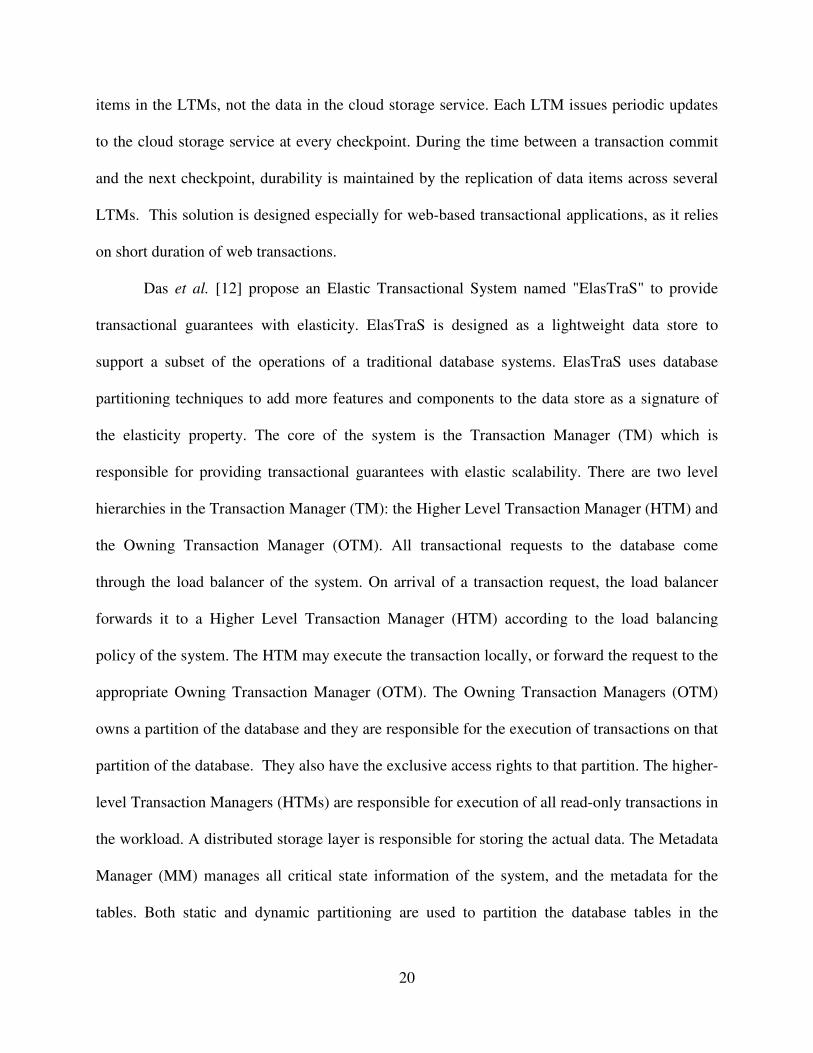
Das et al. [12] propose an Elastic Transactional System named "ElasTraS" to provide
transactional guarantees with elasticity. ElasTraS is designed as a lightweight data store to
support a subset of the operations of a traditional database systems. ElasTraS uses database
partitioning techniques to add more features and components to the data store as a signature of
the elasticity property. The core of the system is the Transaction Manager (TM) which is
responsible for providing transactional guarantees with elastic scalability. There are two level
hierarchies in the Transaction Manager (TM): the Higher Level Transaction Manager (HTM) and
the Owning Transaction Manager (OTM). All transactional requests to the database come
through the load balancer of the system. On arrival of a transaction request, the load balancer
forwards it to a Higher Level Transaction Manager (HTM) according to the load balancing
policy of the system. The HTM may execute the transaction locally, or forward the request to the
appropriate Owning Transaction Manager (OTM). The Owning Transaction Managers (OTM)
owns a partition of the database and they are responsible for the execution of transactions on that
partition of the database. They also have the exclusive access rights to that partition. The higher-
level Transaction Managers (HTMs) are responsible for execution of all read-only transactions in
the workload. A distributed storage layer is responsible for storing the actual data. The Metadata
Manager (MM) manages all critical state information of the system, and the metadata for the
tables. Both static and dynamic partitioning are used to partition the database tables in the

21
ElasTraS system. In static partitioning, partitions of the database are defined by the database
designer, and ElasTraS is only responsible for mapping partitions to specific OTMs. In dynamic
partitioning, ElasTraS performs both database partitioning using range or hash-based partitioning
schemes, mapping the partitions to specific OTMs. The main shortcoming of ElasTraS is it
supports only a subset of the database operations.
Tam Vo et al. [65] introduce LogBase: a scalable log-structured database system which is
able to deploy commodity clusters dynamically to allow the elastic scaling property of cloud
environments. A log-only storage approach is used to overcome the write bottleneck and support
fast system recovery. The basic idea is all write operations are appended at the end of the log file
without being reflected, which means updated into any database, into any data file. The system is
cost-effective in storage usage as the system does not need to store two copies of the data in both
the log and data files. The log files are stored in an underlying distributed file system (DFS) and
are replicated across nodes in the cluster to increase availability and durability.
Vertical partitioning is used to improve I/O performance by clustering columns of a table
into column groups. The column groups are formed and stored separately in different physical
data partitions on the basis of access frequency by the queries in the workload, so that the system
can take advantage of data locality during execution of the queries. LogBase splits the data in
each column group into horizontal partitions to support parallel query processing. Upon arrival
of a write request (Insert or Update), the system transforms the request into a log record with the
<LogKey,Data> format. LogKey indicates the meta information of the write, such as log
sequence number and table name, and Data indicates the content of the write request, such as the
primary key, the updated column group, the timestamp, and the new value of data item. Then the

22
log record is stored into the log repository. The starting offset in the log record and associated
timestamp are used to update the in-memory index of the corresponding updated column group.
To process a read request, the server obtains the log offset of the requested record from
the in-memory index and then retrieves the data record from the log repository. By default, the
system will return the latest version of the data of interest. A delete operation is performed in two
steps: First, it removes all index entries associated with this record key from the in-memory
index. Second, it stores a special log entry (Invalidated Log Entry), into the log repository to
record the information about this Delete operation. The invalidated log entry also follows a
similar <LogKey, Data> format, except the Data component is set to the null value to represent
the fact that the corresponding data record has been deleted. LogBase: is very favorable to
applications that rarely update their data items.
The Deuteronomy system [69] is represented as an efficient and scalable transaction
management system in the cloud by decomposing the system into: a transactional component
(TC) and a data component (DC). The Transactional Component is responsible for only logical
concurrency control and undo/redo recovery, and it has no information about physical data
location. The Data Component (DC) maintains a data cache and supports a record-oriented
interface with atomic operations, but knows nothing about transactions. The Deuteronomy
concept can be applied to data management in a cloud, local, or distributed platform with a
variety of deployments for both the TC and DC. The Deuteronomy architecture is scalable in
three dimensions: (i) Application execution capability can be increased by deploying more
applications servers (TC clients); (ii) More DC servers can be deployed to handle increased
storage and data manipulation workload; (iii) Multiple TCs can be deployed along with separate
DC servers and a disjoint partition of the database to support additional transactional workload.

23
A Deuteronomy TC can be considered as providing Transactions as a Service (TaaS). The idea
of abstraction between a logical transaction manager and physical data storage is very useful for
the data applications in the cloud platform.
Google introduced Spanner [74] the scalable, multi-version, globally distributed and
synchronously replicated database, which is the first ever system that can distribute data at global
scale and support extremely consistent distributed transactions. Spanner has the ability to scale
up to millions of machines across hundreds of datacenters and trillions of database rows. Data is
stored in the Spanner system in schematized semi-relational tables with version information and
timestamps as commit times. Every machine of the Spanner system is time synchronized by very
complex and costly synchronization methods. This system is only used to support Google's in-
house database backbone.
2.4 Examples of Commercial Cloud Databases
Amazon implements a highly available key-value storage system named Dynamo, to
provide 100% availability to some of Amazon’s core service [43]. Dynamo has to sacrifice
consistency sometimes to maintain such high availability. Dynamo uses the quorum protocol to
maintain consistency among its replicas. The quorum protocol will be described in Chapter 4.
Dynamo also follows the consistency relation [7] R + W > N to maintain consistency, where R is
the minimum number of nodes that have to participate in a successful read operation, W is the
minimum number of nodes that have to participate in a successful write operation and N is the
total number of replicas. The slowest R or W replicas are directly responsible for the response
time of a read or write operation.
Some major IT companies have launched relational database services (RDS) in a cloud
platform. Amazon’s RDS and Microsoft’s Azure SQL are pioneers in this field. Amazon does

24
not provide a redundancy server to maintain high reliability. The user has to pay extra for
keeping redundant servers [45]. Usually all read and write requests are handled by the same
server. The user can also maintain some read replicas to share read requests, but the user has to
pay extra for that. Consistency among database servers and read replicas is maintained by the
MySQL built in replica management. All replica servers of Amazon’s RDS are in the same
geographic location, which increases the probability of failure.
Microsoft provides three replica servers to maintain the reliability of Azure SQL services
[44, 91]. All read and write requests are handled by a primary server. If the primary server goes
down, the first secondary server will take responsibility and the second secondary server will
take responsibility after the first secondary server is down. The quorum protocol is used to
maintain consistency among replicas of Azure SQL server.
Another popular cloud relational database service was launched by Xeround [38].
Xeround maintains a configurable number of replicas for a database. The quorum protocol is also
used to maintain consistency among replicas in Xeround. Read or write operations are sent to a
coordinator to complete an operation. The coordinator maintains communication among replicas
and this communication is different for read and write operations.
Much research needs to be done to address the issue of consistency for transactional
databases in a cloud. In the next chapter we propose an approach that involves maintaining
consistency by minimizing the inconsistency and maximizing the performance in an efficient
manner.

25
CHAPTER 3
TREE-BASED CONSISTENCY (TBC)
In this section we present our tree-based consistency approach for transactional databases
in clouds. As described in Chapter 2, a cloud system is distributed and has its data replicated to
increase the reliability and availability of the system. A transactional database in a cloud can
utilize this distributed and replicated nature of a cloud. A transactional database assumes that
write operations to the database will routinely occur. However, a write operation to a replicated
distributed database is different than a write operation to a typical centralized database. The
consistency maintenance that is required among the replicas of a database is responsible for the
differences.
In a distributed database with replication, one of the replicas can be designated as the
primary (or master) replica. Once a master replica receives a write request, it takes several
additional steps to inform its slave replicas about the write request. The additional steps to
inform slaves could be a PUSH or PULL based strategy [36]. In a PULL based system, the
primary replica keeps a log entry for every write operation to the database and slave replicas
periodically pull those entries from the log file of the primary replica in order to execute the
write operations locally. In a PUSH based system, the primary replica itself forwards the write
request to the slave replicas and the slave replicas execute the write request locally. Slave
replicas may or not inform the primary replica about a successful execution of the write request;
it depends on the implementation of the system.

26
The ACID properties are the key properties of a transactional database system. As
mentioned previously, the ‘C’ of ACID indicates consistency of a database. Any changes due to
a write operation to the database must follow all defined rules and constraints of that database. If
a write operation violates any rules and constraints of the database, then the entire transaction
will be rolled back to restore the consistency of the database. If all the write operations of a
transaction satisfy the rules and constraints, then the transaction has been executed successfully
and the entire database will be transformed from one consistent state to another consistent state.
This means a consistent database will remain consistent after the execution of every write request
of a successful transaction.
A cloud database can be replicated over a wide geographic area to increase availability
and reliability. Consistency maintenance is somewhat harder for a replicated cloud database as
all replicas need to communicate with a network. All network parameters, such as bandwidth,
traffic load and packet loss, play important roles in consistency maintenance. Sometimes
communication paths may become unreliable or sometimes the network path may become very
congested due to a huge traffic load. These may result in a very large number of requested update
operations in a queue, an exponential increment of update response time, or even repeated
unsuccessful transactions, all of which degrade the overall performance. Cloud infrastructure is
typically built using heterogeneous systems, so some servers may be very slow compared to
others. These slow cloud servers become a bottleneck to the system, which may lead to slow
response time and overall performance degradation. The bottleneck can have an effect on the
strategy to maintain consistency. Our tree-based consistency approach, called TBC, addresses
the maintenance of consistency with minimal performance degradation.

27
In our TBC approach, a tree defines the path that will be used by the replica nodes to
communicate the updates from one replica to another. This is in contrast with the classical
approach, in which one designated node must notify all other replicas about an updates. In our
proposed approach, a replica only needs to notify a subset of the replicas about an update. These
replicas in turn notify a different subset of replicas about the updates. We consider multiple
performance factors, such as disk update time, workload, reliability, traffic load, bandwidth and
network reliability when building the tree. We also limit the maximum number of children that
each parent can have in the tree to minimize the effect of interdependency on performance. An
increase in the number of children per node requires each parent to wait until all children have
performed the updates, in effect to be dependent on the child updates. This impacts the building
of the tree. We note that by limiting the number of children, we can minimize this update
dependency between parent and children. These restrictions on the number of children and the
addition of the performance factors change the algorithm needed for the creation of tree. The
TBC approach reduces the window of inconsistency, and provides a new type of consistency,
called apparent consistency.
The structure of the tree affects the performance of this approach. The multiple
performance factors taken into account when creating the tree are discussed in Section 3.2 and
Section 3.3.
3.1 System Description
Our TBC strategy requires the inclusion of the following two components in a cloud
database system: a Controller and Database Replicas. (See Figure 2)
i) Controller: There may be two or more controllers in this system. It can be implemented
as a standalone server or an independent process run on a database server. The tasks of
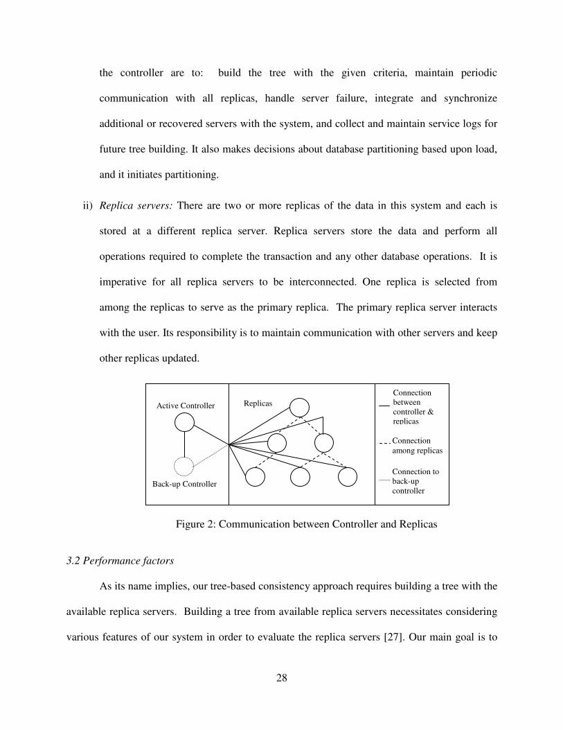
28
the controller are to: build the tree with the given criteria, maintain periodic
communication with all replicas, handle server failure, integrate and synchronize
additional or recovered servers with the system, and collect and maintain service logs for
future tree building. It also makes decisions about database partitioning based upon load,
and it initiates partitioning.
ii) Replica servers: There are two or more replicas of the data in this system and each is
stored at a different replica server. Replica servers store the data and perform all
operations required to complete the transaction and any other database operations. It is
imperative for all replica servers to be interconnected. One replica is selected from
among the replicas to serve as the primary replica. The primary replica server interacts
with the user. Its responsibility is to maintain communication with other servers and keep
other replicas updated.
Figure 2: Communication between Controller and Replicas
3.2 Performance factors
As its name implies, our tree-based consistency approach requires building a tree with the
available replica servers. Building a tree from available replica servers necessitates considering
various features of our system in order to evaluate the replica servers [27]. Our main goal is to
Connection
between
controller &
replicas
Active Controller
Back-up Controller
Replicas
Connection
among replicas
Connection to
back-up
controller

29
maximize performance, so we have to find out the main causes behind performance degradation.
As mentioned previously, a cloud computing infrastructure is almost always built with
heterogeneous components. Some servers are computationally slow, while other servers are
computationally fast but are highly loaded with jobs. Some servers take a large amount of time
to make a disk update, while other servers take a large amount of time to relay an update
message and some servers are not reliable enough. Some servers are connected by a slow
network, other servers reside in highly loaded networks, and some servers reside in less reliable
networks. All of these heterogeneous characteristics of a cloud infrastructure can cause
enormous performance degradation.
We have taken some of these important characteristics into consideration to evaluate
servers and their connection network of the replica servers in order to build the consistency tree.
We call these characteristics, performance factors, pf. The performance factors and their
consequences are given below:
i) Time required for a disk update: The originating server for the request will have to wait
until all necessary servers reply. If a replica server spends a large amount of time in a
requested update operation for a disk update, then the effective response time for an
update operation will be increased. This may cause overall performance degradation,
performance bottleneck and an exponential increment in response time may result.
ii) Workload of the server: Response time for a job is proportional to the workload of the
server. If a replica server is overloaded then it will introduce a very large delay in
response time.
iii) Reliability of the server: A cloud computing infrastructure is typically built with cheap
servers. Server failure is a very common scenario in a cloud computing platform. If a

30
replica server fails, another server can be replaced by a new server within a reasonable
amount of time. However, this reasonable amount of time increases the response time
temporarily. Because we introduce a database state that is partially consistent in our
system, the impact of server failure is more important to this system in terms of its impact
on consistency.
iv) Time to relay a message: An update request propagated according to a tree structure
reaches a leaf node after being relayed by several servers. In a partially consistent
database, an inconsistency window, which is the time required to update all servers,
depends on the time to relay a message.
v) Reliability of network: If an update request is lost due to network unreliability, another
update request will be sent after a request time out (predefined certain amount of time).
As a result, a significant amount of delay will be introduced in the response time.
vi) Network bandwidth: If there is not a high network bandwidth, there is more transmission
delay.
vii) Network load: Sometimes a huge amount of traffic on a high capacity transmission path
may also introduce a significant amount of delay.
Taking all of these characteristics of our performance factors into consideration, we
introduce a new performance evaluation metric, called PEM. Each performance factor has a
weight factor which indicates its importance relative to the other factors. Obviously, the weight
factor can vary per system, just as each system can include a different subset of performance
factors. Each performance factor is multiplied by the appropriate weight factor to capture its
effect on the response time of an update request. If the response time of an update request in a

31
system depends on n performance factors, then Equation (1) describes the formula for calculation
of the evaluation metric PEM for that system, where pfj is the jth
performance factor and wfj is the
corresponding weight factor. As described later, the constrained Dijkstra’s algorithm will use
PEM in building the consistency tree from the connection graph.
��� = ∑ (�∗
�)�
��� ..........................................................................(i)
3.3 Building the Tree
It is the controller’s responsibility to calculate the evaluation metric PEM and prepare the
consistency tree accordingly. Based on the tree, the controller informs all servers about their
responsibility and also notifies the clients as to the responsible server for communication. The
information and operation logs of servers and network connections collected by the controller are
used for calculation of the performance factors and weight factors. The tree building process
requires the following steps.
i) Preparing the connection graph: The controller will first prepare the weighted
connection graph G (V, E) where V stands for the set of vertices and E stands for the set
of edges. Each replica server is a vertex, and therefore, is a member of set V. All direct
connections among replica servers are considered as edges and members of set E. A
separate performance factor matrix is prepared for every performance factor that will be
considered, since G is a weighted connected graph. Figure 3(a) illustrates a connection
graph with six vertices.
ii) Selecting the root of the tree: The controller will select the root of the tree which will be
the primary replica server. The primary server is the server which is the connection to the
user. The controller will calculate a PEM value for each server from the performance

32
factors (pf) of servers and corresponding weight factors (wf), and chooses as the root the
server who has the maximum value. Figure 3(d) and figure 3(e) illustrate the
performance factors (pf1 = time delay and pf2 = reliability of the server). Weight factors
wf1= -.02 and wf2= 1 are used in this example. Node 5 is chosen as the root.
(a) Interconnection Graph (b) Time Delay W[pf1] (c) Path Reliability W[pf2]
(d) Time Delay R[pf1] (e) Path Reliability R[pf2] (f) Consistency tree
Figure 3: Example of a Tree Calculation
iii) Preparing the consistency tree: After selection of the root controller, the consistency tree
will be prepared from the weighted connection graph. The controller will apply Dijkstra’s
single source shortest path algorithm with some modification. The root of the tree will be
selected as the single source. The modified Dijkstra’s algorithm shown in Algorithms 1-
5 will find a suitable path to every replica server to maximize performance and all paths
together will form the consistency tree. The algorithm also imposes a constraint on the
maximum number of children for a parent node. We describe Dijkstra’s algorithm as
modified because it must accommodate the limitation that is placed on the number of
children in the resulting graph. The maximum number of children that a parent node can
have depends on the tradeoff between reducing interdependency to minimize the
1 .9 0 .8 0 .9
.9 1 .8 0 .9 0
0 .8 1 .9 .6 .7
.8 0 .9 1 .9 0
0 .9 .6 .9 1 .7
.9 0 .7 0 .7 1
0 25 0 20 0 15
25 0 26 0 17 0
0 26 0 15 24 20
20 0 15 0 19 0
0 17 24 19 0 22
15 0 20 0 22 0
50 20 60 30 10 30 .98 .98 .91 .93 .99 .96
1
6 2
5
4
3
5
4 2
1 6 3

33
response time of an update operation and maximizing the consistency and reliability of a
database. Figure 3(b) and figure 3(c) illustrate the performance factors (pf1 = time delay
and pf2 = path reliability). Weight factors wf1= -.02 and wf2= 1 are used in this example.
The maximum children constraint was set to 2 in this example. The resulting tree appears
in Figure 3(f).
Algorithm 1 :Modified_Dijkstra (G, V, E, P, N, W)
1 // G is connection graph with V vertex set, E edge set
2 //P is 3D array, all pf values of each path
3 //N is 2D array of pf values of each node
4 // W is 1D array of wf values regarding all pf
5 s�Find_Max (V, N, W)
6 Initialization(V, s)
7 S � Φ
8 Q � V
9 while Q isn’t empty
10 u�Find_Max (Q, N, W)
11 S �S U u
12 remove u from Q
13 num_child[ Π [u]] �num_child[ Π [u]] + 1
14 if num_child[Π [u]] > Max_Child then
15 Reweight(Π [u], S, Q)
16 end if
17 for each vertex v ɛ Adj[u]
18 Relax(u, v, P, N, W)
19 end for
20 end while
Algorithm 2: Initialization (V, s)
1 for each vertex v ɛ V
2 Π [v]� nil
3 num_child[v] � 0
4 for each pf
5 if pf to be minimized then
6 D[pf][v]� ∞
7 else if pf to be maximized then
8 D[pf][v] � 0
9 end if
10 end for
11 end for
12 for each pf
13 if pf to be minimized then
14 D[pf][s] � 0
15 else if pf to be maximized then
16 D[pf][s] � ∞
17 end if
18 end for

34
Algorithm 3 :Find_Max (V, N, W)
1 //V= vertex set, R=pf values of nodes, W=wf values
2 max_pem � 0
3 pem � 0
4 s� nil
5 for each vertex v ɛ V
6 for each pf
7 pem�pem + N[pf][v] * W[pf]
8 end for
9 if pem>max_pem then
10 s� v
11 end if
12 end for
13 retrun s
Algorithm 4: Reweight (p, S, Q)
1 for each v ɛ Q and Π [u] = p
2 for each pf
3 if pf to be minimized then
4 D[pf][v]� ∞
5 else if pf to be maximized then
6 D[pf][v] � 0
7 end if
8 end for
9 for each u ɛ S and u ≠ p and u ɛ Adj[v]
10 if num_child[u] <Max_Child then
11 Relax(u, v, P, N, W)
12 end if
13 end for
14 end for
Algorithm 5: Relax (u, v, P, N, W)
1 for each pf
2 old_pem�old_pem + D[pf][v] * W[pf]
3 new_pem�new_pem+ƒ(D[pf][u],P[pf][u][v],N[pf][v] )*W[pf]
4 // ƒ can be addition, multiplication or any arithmetic function
5 end for
6 if new_pem>old_pem
7 for each pf
8 P[pf][v] � ƒ(P[pf][u],W[pf][u][v],R[pf][v])
9 end for
10 end if
11 Π [v]� u

35
The time complexity of the modified Dijkstra's algorithm in Algorithm 1 is O(mn2)
where m is the number of performance factors and n is the number of nodes. The complexity of
the Find_Max function in Algorithm 3 is O(mn), the complexity of the Initialize function in
Algorithm 2 is O(m+n), the complexity of the Reweight function in Algorithm 4 is O(mn) and
the complexity of the Relax function in Algorithm 5 is O(m). Hence, the overall complexity of
the algorithm is O(mn) + O(m+n) + O(m) * (O(mn) + O(mn) + O(m)), which is O(mn2). If we
use a heap structure instead of array, then complexity is reduced to O(mn log n). Because the
number of nodes (n) is small, the difference between O(mn2) and O(mn log n) is not large, so for
simplicity we use a simple array instead of a heap.
The granularity of the replicas upon which the tree is based can be the entire database, a
table or a subset of tables in the database. Similarly, a tree can be recalculated periodically to
reflect any changes in the performance factors or its recalculation can be triggered by a specific
event, such as a failure or exceeding some threshold.
3.4 Update Operation
The controller informs all replica servers about its immediate descendants. Each replica
is responsible for maintaining the updates of its own descendants and each update operation has
a unique sequence number associated with it. Each replica server maintains a queue of pending
update requests and each replica stores two state flags:
i) Partially consistency flag: The last updated operation sequence number is stored as the
partially consistent flag. A partially consistent flag is set using a top-down approach. In
other words, if we traverse from a node (replica server) to the root of the tree, for a
particular update, all these nodes have the same sequence number stored as their partially
consistent flag.

36
ii) Fully consistent flag: A fully consistent flag is set by a bottom-up approach. A fully
consistent flag is also an update operation sequence number. It indicates that any node
that is a descendant of a sub-tree also has the same update sequence number stored as its
fully consistent flag.
When the root receives an update request, it will store the request in a request queue. The
request queue is used to maintain serializability at the root node of the tree as will be discussed
shortly. The update process at the root continuously monitors the queue. When the replica server
is available, an update request is dequeued to initiate an update operation. An update operation is
done using the following four steps.
a) An update request will be sent to all children of the root
b) The root will continue to process the update request on its replica
c) The root will wait to receive confirmation of successful updates from all of its children
d) A notification for a successful update will be sent to the client
Update operations at non-root nodes are handed differently. There are two different
possible approaches to updating the partially consistent flags.
i) A node receives an update request and it initiates the required steps to update itself. The
update request is then stored in its queue. When the update is done successfully a node
will notify its parent and store the update sequence number as its partially consistent flag.
To propagate an update request, the node dequeues an update request from the queue,
sends the request to all its children, and waits until all of its children reply with a
successful update before its sends the next update request from queue. However, this
approach increases the effective inconsistency window.

37
ii) A node receives an update request and it will relay the update request to all of its
children. The node checks the possible conflicts of the update request before it takes the
initiative to update itself. When an update is done, it will notify its parent and store the
update sequence number as its partially consistent flag. It will store an update request in a
queue to keep track of all children that can successfully complete the update or not. When
all children reply back to an update request, the corresponding update will be removed
from the queue. The inconsistency window is smaller in this approach.
Storing the fully consistent flag is initiated by leaf nodes. When a leaf node is done with
an update request, it stores the sequence number as both the partially consistent flag and fully
consistent flag. It then informs its parent about storing its fully consistent flag. All intermediate
nodes will notify their parent when they receive notification from all of their children.
3.5 Maintaining Consistency
A request for a Read operation to the data will always return a value from either the
replica that is the root node or one of the immediate descendants of the root node, as these values
will always reflect the most recent updates. The structure of the tree itself determines how many
replicas can serve in this capacity. If all nodes are immediate descendants of the root node, then
this is considered the classic approach. In the classic approach, all replicas must be updated
before any Read can occur, so the response time is increased. Fewer immediate descendants of
the root node will result in a decrease in response time for updates, but increase the workload on
the root node and its immediate descendants.
The root node of the tree is responsible for making sure all of the replicas in the tree are
updated once a Write operation is issued. Hence, in our approach, we consider one replica as
responsible for update operations and several replicas to manage durability and reliability.

38
3.6 Auto Scale Up
One of the key features of a cloud platform is to prevent the user from having to worry
about the variable nature of the workload. Cloud systems should be able to handle an increased
workload automatically. If the workload exceeds the threshold limit of the root node, the
controller takes the initiative for handling the excess load. This process is done by the following
steps:
i) The Controller uses may add more servers to the consistency tree or build a new
consistency tree. From the available servers, the controller calculates PEM values to
identify the servers needed to added to the tree or build a new tree. The tree building
process follows the same steps described in Section 3.3.
ii) If a new tree is built, the database needs to be partitioned. The Controller makes the
decision about the partition, which is a complex process. The following factors may
affect the partition decision: relationships between the data, nature of the data,
importance of the data and response time tolerance.
As the load continues to increase, the controller follows the same steps as long as the load
exceeds the total capacity of the current system. If the workload decreases beyond a threshold
limit, underutilized servers need to be removed from the system. The controller initiates such a
process. Sometimes the partitions will need to be merged to complete the scale-down process.
The details of the auto-scaling process are discussed in chapter 7.
3.7 Number of Maximum Allowable Children
The performance of TBC is also dependent on the number of children of the root node. If
the root has a large number of children, the interdependency increases which leads to possible

39
performance degradation. If the root has a fewer number of children, then interdependency
decreases, but it leads to less reliability and possible data loss. The number of children of the root
node that is allowed should be a tradeoff between performance and reliability.
We have conducted an experiment to support our idea. In this experiment, we wanted to
study the effect of the density of the tree on the response time. The density of the tree is affected
by the number of children each node has. In the experiment, we consider three categories of
trees: sparse, medium and dense. The three different types of trees are illustrated in Figure 4(a).
For sparse trees, the root has two children and each of the other nodes has only one child. The
resulting height of the tree was four. For our medium density tree, the root has three children
and each of the remaining nodes has two or one child. The height of the medium tree was three.
For our dense tree, the root has four children and the remaining nodes each have one child. The
height of the tree was two.
We have performed the experiments to study the effect of the density of the tree on the
response time on a green cluster called Sage, built at the University of Alabama, which we
describe in more detail in Chapter 4. A standalone java program runs on each node in the Sage
cluster to perform the update operation, which is defined as a certain amount of delay in
execution. In this experiment we have included only write operations. When the server receives
an update request, it will wait a certain amount of time t before sending a reply indicating a
successful update, where t = op + wl (op represents the actual time required for a disk operation
and wl represents a delay due to the workload of the disk and operating system). A uniform
random variable is used in the calculation of wl. The time duration between two consecutive
update operations is determined by a Poisson random distribution. The arrival of write

40
0
50
100
150
200
250
sparse medium dense
Re
spo
nse
Tim
e (
Mill
ise
con
d)
Tree Density
Tree Density vs Response Time
TBC
operations is decided by a Poisson random variable with λ= 0.2. We calculated a random
variable every 10 ms and the probability of arrival of a write operation is 0.2.
(a) Sample Structure of the Trees (b) Effect of density of the tree
Figure 4: Effect of Sparse and Dense Trees on the TBC Approach
In Figure 4(b) the x-axis of the graph represents the different levels of density of the tree
and the y-axis of the graph represents elapsed time in milliseconds. As expected and as indicated
by Figure 4(b), the response time increases as the density of the tree increases. The response time
in Figure 4(b) ranges from 134 ms for the sparse tree, to 166 ms for the medium tree, to 227 ms
for the dense tree. A sparse tree results in a faster response time for the TBC approach, but has
fewer immediate children of the root node and fewer updated replicas that are available for
access by the client. Conversely, a dense tree has a slower response time, but more updated
replicas available. The TBC approach provides a framework that allows for trading off the
availability and consistency with the performance.
3.8 Inconsistency Window
An inconsistency window is a drawback occurring in a distributed database. In a
distributed system, all nodes of the system are actually deployed in different geographic
locations and they are connected over a network. Communication between these nodes can be
sparse medium dense

41
time consuming. For a distributed database system, it takes time to conduct a write operation
with all relevant nodes. If the system waits for all nodes to confirm completion of a write
operation, then the processing of the next write operation will be delayed. Some consistency
approaches [10, 13, 39] accelerate processing of the write operations by initiating processing of
the next write operation after receiving confirmation from a certain number of nodes (from 1 to
many nodes), and not waiting for all nodes to reply. The duration of the time frame between the
system confirmation of completion of the write operation and the actual completion of all the
write operations is called the Inconsistency Window. That means an inconsistency window is the
amount of time the system is inconsistent.
We have conducted an experiment to measure the inconsistency window for TBC. We
have also included a modification to our TBC strategy that is designed to decrease the
inconsistency window, and call this modified TBC strategy MTBC. We want to study the effect
on the response time of decreasing the inconsistency window. The modification is to have the
root of the tree send a write request to all nodes instead of only sending a write request to its
immediate children. However, the root will wait for a reply only from its immediate children,
not all of the nodes in the tree. Like TBC, in MTBC, the root can process the next write
operation after receiving confirmation of a successful update from all of its immediate children.
Like TBC, every parent node except the root is responsible for waiting for replies from all of its
children. Modified TBC can reduce the inconsistency window length, but it increases the
chances of possible conflicts and increases the complexity of addressing those conflicts.
In this experiment we have included only write operations. Similar to the experiment in
the previous section, the arrival of write operations is decided by a Poisson random variable with
λ= 0.2. We calculated a random variable every 10 ms and the probability of arrival of a write

42
operation is 0.2. In this experiment we have processed one thousand operations. Figure 5 shows
the inconsistency window length in milliseconds for both TBC and MTBC. TBC has an
inconsistency window of 144 ms and MTBC has an inconsistency window of 109 ms. In the
TBC approach, nodes that are updated after the immediate child nodes of the root complete their
updates do not participate in a read request. This is because only the values at the root and its
immediate children provide their values for a read operation. As a result, the length of the
inconsistency window does not impact the response time of the Tree-based system. We utilize
TBC through remainder of this dissertation.
Figure 5: Inconsistency Window
3.9 Failure Recovery
We assume any server or communication path between two servers can go down at any
time. It is the responsibility of the controller to handle such a situation. There are two types of
situations:
i) Primary server is down: The controller maintains continuous communication with the
primary server. If the controller is able to determine that the primary server is down, it
will communicate with the immediate descendant of the root server concerning its
0
50
100
150
200
250
300
350
400
TBC MTBC
Tim
e in
Mill
ise
con
d
Consistency Approaches
InConsistencyWindow
InConsistencyWindow

43
partially and fully consistent flag. If both flags are the same, the controller will choose a
new root from all servers. If both flags are not the same, then the controller will find the
servers with the latest updates by querying which immediate descendent has the same
sequence value for its partially consistent flag as its own. From among these latest
updated servers the controller will find the root. The connection graph is then
reconfigured with all available servers and the consistency tree is built using the strategy
described in Section 3.3.
ii) Other server or communication path is down: If the unresponsive behavior of an
immediate descendant is reported at any time by an intermediate node, the controller tries
to communicate with that server. The controller will fail to communicate with the server
if it is down. The connection graph is then reconfigured without that server, the
consistency tree is built with the same root and all servers are informed about the new
tree structure. In the event the communication path is down, the controller can still
communicate with the server via another path. The controller will then reconfigure the
connection graph including the server and build the consistency tree as described in
Section 3.3.
The TBC approach reduces interdependency between replicas because of the fact that a
replica is only responsible for its immediate descendants. When a replica is ready to perform an
update, it only has to inform its immediate descendants, receive acknowledgements from them
and update its data. Hence, the transaction failure risk due to interdependency is reduced
regardless of the network load, bandwidth and other performance factors.

44
3.10 Apparent Consistency
In our TBC approach, the primary server only waits until its children have updated their
replicas until it responds to the client. This means not all of the replicas will have completed
their updates, particularly those further down the tree and closest to the leaf nodes, before a
response is provided to the client. However, the TBC strategy ensures that any subsequent Read
of the data will read the most recent update to the data. This is because subsequent data reads
will occur at the highest level of the tree, where the Writes have been completed. Since the
primary node will have more than one descendent, there will always be several replicas with the
most recent updated values. However, instead of waiting until all replicas have been updated
before responding to the client, TBC ensures a subset of the replicas are current. The process
continues at the lower levels of the trees, so that all updates will continue to be applied to all
replicas.
A client will always see any update, since it will access one of the replicas at the upper
level nodes of the tree. This means that from the client view, there is a consistency. We note
that this is not the same as the typical strong consistency since not all of the replicas will be
updated at the same time. However, since a client will only view an updated data value, we call
it apparent consistency. The bottlenecks and increases in workload, as a result of accessing
replicas from the top levels of the tree, can be addressed by partitioning the data and periodic
restructuring of the tree. We consider such issues in Chapter 7.

45
CHAPTER 4
PERFORMANCE ANALYSIS OF TBC
The system architecture, operational environment, operational load, and performance
expectation of data management applications can all be different. Data management applications
must be dynamic in order to respond to the changing nature of computing today. Determining
which consistency approach will perform better depends on the current conditions in a cloud.
The main goal of this chapter is to explore the characteristics of several consistency techniques
and find out the best techniques in different operational conditions. To this end, we have
implemented a simulation application that uses MySQL. We study the effect of the system load,
read/write ratio and network reliability on the performance of the three consistency strategies of
classic, quorum and TBC.
4.1 Classic Approach
According to the first consistency approach that we will study, a data value is not
returned for a read or a write operation until all replica copies can return the same value. That
means when an update operation is requested to a replicated database system, all replicas of the
system need to be updated to complete the request. However, according to the previously
discussed consistency relation (W+R > N), only one replica from a read set is needed for a read.
Figure 6 illustrates the classic approach, assuming 6 replicas reside at 6 different nodes in
the network. One of the 6 nodes is designated as the primary node. As shown in Figure 6(a),
once a write to data X is requested at the primary node, the request is sent to all nodes containing

46
replicas of data X. The data is not available until all replica nodes have acknowledged to the
primary that they have updated X. It is only at this point, that the data can be read from or written
to by a subsequent request. As also shown in Figure 6(b), a read request only requires one node
to return the value of data X to any secondary replica. We expect the classic approach to have a
better response time when serving applications with many reads, but few write operations.
(a) Write Request (b) Read Request
Figure 6: Write and Read Techniques of the Classic Approach
4.2 Quorum Approach
Quorum based voting is used for consistency maintenance in systems, such as Amazon’s
Dynamo [43]. In actual quorum voting, a decision can be made when a majority of the members
agree with a particular decision. Accordingly, a quorum-based consistency system requires more
than half of the replicas to complete a read or write operation before the data is available for a
subsequent read or write. There is no specific primary or secondary replica in quorum-based
systems. Any replica can perform as the primary, and subsequent read or write operations are
sent to every node periodically. For a read operation, the majority of the replicas must return the
same (updated) value before a read can occur.
User
Controller Read Request
Result Return
Secondary
Primary
User
Controll
er
Primary
Secondary
Write Request
Acknowledgement

47
As shown in Figure 7(a), a write request to data X is sent from the primary to every node
with a replica of data X. Data X is not available for a read or write until a majority of the nodes
reply. In other words, when a subsequent write or read is requested, the subsequent write or read
can proceed only after a majority of the nodes send a reply acknolwedging a successful update to
the primary of data X. As shown in Figure 7(b), a read requests for data X is also sent from the
primay node to every node with a replica of data X. A read can proceed only after a majority of
the nodes return the same (updated) data value to the primary node. We expect the quorum
approach to offer better response time than the classic approach to applications with many write
operations.
(a) Write Request (b) Read Request
Figure 7: Write and Read Techniques of the Quorum Approach
4.3 Tree-Based Approach
In our tree-based consistency approach, a tree defines the path that will be used by the
replica nodes to communicate with each other to propagate the update requests. In our proposed
approach, a replica only needs to notify a subset of the replicas about an update request. As
shown in Figure 8(a), to process a write request to data X, the root node notifies it immediate
Read Request
Result Return
Secondary
Primary
Controller
User
Write Request
Acknowledgement
User
Primary
Controller
Secondary

48
descendants in the tree to update their replica of data X. Once these nodes send an
acknowledgement to the root (primary node) that their update has been successfully completed,
subsequent writes and reads can occur to data X. A subsequent write requires the root to again
notify its immediate descendants of a write operation. As also shown in Figure 8(b), for a read
operation, the replica at the root node or one of its immediate descendants returns the value to be
read.
As illustrated by Figure 8 and discussed in detail below, the replicas below the immediate
descendants of the root node are also notified of the update to data X, as this update is
propagated down the tree. However, any new updates or reads take place at the top two levels of
the tree, which are guaranteed to be strongly consistent. We expect a faster response time for a
read, but maybe slower for a write operation.
(a) Write Request (b) Read Request
Figure 8: Write and Read Techniques of the Tree Based Consistency Approach
4.4 Experimental Environment
We designed experiments to compare the performance of the classic, quorum and TBC
approaches. We have performed our experiments on a cluster called Sage, which is a green
Read Request
Request Reply Controller
User
Secondary
Primary
Write Request
Acknowledgement
User
Controller
Primary
Secondary
Synchronization

49
prototype cluster that we have built at the University of Alabama. Our Sage cluster currently
consists of 10 nodes, where each node is composed of Intel D201GLY2 mainboard with 1.2
GHz Celeron CPU, 1 Gb 533 Mhz RAM, 80 Gb SATA 3 hard drive. The cluster nodes are
connected to a central switch on a 100 Megabit Ethernet in a star configuration, using the
D201GLY2 motherboard on-board a 10/100 Mbps LAN. The operating system is Ubuntu
Linux 11.0 server edition. Shared memory is implemented through NFS mounting of the
head node's home directory. The Java 1.6 platform was used to run our simulation program
written in Java. MySQL Server (version 5.1.54) was set up on each node to implement
database replicas.
4.5 Experiment Design
A simulation program was developed to manage read and write requests to the
database. The classic, quorum and tree-based consistency approaches are implemented in
every node of the cluster. All user requests pass through a gateway to the cluster. Response
time is the metric used in our experiments. Response time is measured as the time difference
between a database request transmission and the response reception of that request.
Acknowledgement-based network communication is implemented. Because the LAN
connection of the cluster is very secure and fast, the transmission time of a packet among the
nodes is much faster than that of nodes in different datacenters across the country. To solve
this issue, we have calculated the transmission time used in our experiments by interpolating
the ping response times of different servers across different regions of the country. We also
observed several thousands of ping histories to determine traffic congestion and packet loss
on every network path. We found a 0% to 0.05% packet loss, with 0% to 10% of packets
affected by network congestion.

50
During an experiment, a Poisson random distribution value is calculated every 10 ms
to decide whether a database request should be sent or not. Whether a request should be a
read request or write request is decided by a uniform random distribution value. Each read
request is represented by a single query to a MySQL database and each write request is
represented by a single insertion into a MySQL database. We created a relational database
that is replicated in every node in the cluster. Figures 6-8 illustrate the corresponding read
and write queries to the MySQL databases. Thousands of requests are sent to determine the
average response time.
Table 1 shows the default values used in the experiments. Request arrival rate λ means
the possibility of a request arrival in every 5 ms period. The default value of λ is 0.1, meaning
there is a 10% chance a request will arrive every 5 ms. The percentage of read to write
requests is 70% to 30%. We define network congestion as an unusual delay in packet
transmission time. We have observed that in a regular network, up to 10% of the packets are
delayed due to network congestion. Network congestion value Regular means up to 10% of
the packets will be delayed due to network congestion. The amount of delay due to network
congestion is computed by a random variable from 1 to 10%.
Table 1: Default Parameters
Parameter Name Default Value
Request Arrival Rate λ 0.1
Arrival Unit Time 5 ms
Read/Write Ratio 70%-30%
Network Congestion Regular
Packet Loss 0.05%

51
The probability of a transmission failure is 0.05 % and is implemented as follows. A
timer is turned on for each transmitted packet. The packet will be retransmitted periodically
unless its timer has stopped due to the receiver acknowledging receipt of that packet. A
uniform random distribution value is calculated before transmission of each packet to decide
the successful transmission of that packet; thus, transmission failure probability is
implemented.
4.6 System Load Calculation
Two of the techniques, classic and TBC, use a centralized point of entry for write
requests, whereas the quorum technique uses a distributed point of entry for write requests. A
centralized point of entry could be a possible bottleneck in the system. In this section, we
calculate the load of the system for each of the three techniques.
The load of the server has two parts: load due to disk operations and load due to CPU
usage. We assume the load due to disk operations is the amount of time required to complete
a disk operation and the load due to CPU usage is the amount of time the CPU has to spend to
complete a read or write operation. The number of write operations is denoted as W and the
number of read operations as R. DWP denotes a disk write time for the primary server and DWS
for a secondary server, DRP denotes the disk read time for a primary and DRS for a secondary
server, CWP denotes CPU usage time for a write by the primary server and CWS for the
secondary, and CRP denotes CPU usage time for a read by the primary and CRS for a secondary
server. We denote the load of the primary server as PL and the load of a secondary server as
SL. The amount of time the system spends to process W write and R read operations is PL +
SL.

52
In the classic technique, the primary server handles the load for write operations while
the secondary servers handle the load for read operations. Obviously, every secondary server
has to participate in each write operation to maintain consistency within the system, where:
PL = ( DWP + CWP ) * W ...................................................................................... (ii)
SL = ( DWS + CWS ) * W + ( DRS + CRS ) * R ....................................................... (iii)
In the quorum technique, servers participate in every read and write request and any
node can act as the primary node with the remaining nodes serving as secondary nodes:
PL = ( DWP + CWP ) * W + ( DRP + CRP ) * R ...................................................... (iv)
SL = ( DWS + CWS ) * W + ( DRS + CRS ) * R ........................................................ (v)
In TBC, the root handles the load of write operations while the immediate children of
the root handle the load for read operations. Every immediate child of the root has to
participate in each write operation to maintain consistency. We denote load of the root as PL
and the load of its intermediate children as SL.
PL = ( DWP + CWP ) * W ...................................................................................... (vi)
SL = ( DWS + CWS ) * W + ( DRS + CRS) * R ....................................................... (vii)
We have performed a simulation in which we ran thousands of experiments with
MySQL queries as described in Section 4.2. We measured the amount of time for a server to
serve the disk load and the CPU load. We use a 70-30 read-write ratio and assume six nodes
in the experiment. The structure of the tree for TBC is the same as Figure 3 in Section 3.3. All
times are measured in milliseconds.

53
Table 2 shows the measured values resulting from the experiments for each of the
three approaches for the primary and secondary servers. The average amount of time a server
spends to process an operation can be calculated by adding the disk and CPU times, and
multiplying this sum by the appropriate read or write percentages. On average, for the classic
approach, the primary server spends 26 ms per operation ((31 + 55) * 0.3) and secondary
servers spend 11.78 ms per operation. On average, any quorum-based servers spend 34 ms per
operation. On average, the root of the TBC system spends 14 ms per operation and its
immediate children spend 13.8 ms per operations. Quorum servers have to spend a longer
amount of time than others. When the ratio of write operations is low compared to read
operations, the quorum always has to spend more time on average per operation. Because we
consider average time per operations in our analysis, the arrival rate has no effect on the
analysis. Our results demonstrate that a single point of entry for a write operation will not
result in a bottleneck to the system with a 70-30 read-write ratio.
Table 2. Read/Write Times (CPU + Disk)
Classic Quorum TBC
Read Write Read Write Read Write
Primary Disk 31 16 17 16
CPU 55 23 25 30
Secondary Disk 15 21 16 17 18 19
CPU 7 8 16 18 12 11
In the next section we study the performance of the TBC approach as we vary the
database request rate, read-write ratio, network quality and heterogeneity of servers.

54
4.7 Effect of the Database Request Rate
We first study the effect of different arrival rates of update requests by changing the
value of λ. Figure 9 illustrates the results when the arrival rate increases from 0.01 to 0.8. A λ of
0.01 means every 5 ms, there is a 1% chance a request will arrive, and a λ of 0.8 means there is
an 80% chance a request will arrive every 5 ms. The remaining values used in this experiment
are the default values appearing in Table 1.
The x-axis of the graphs in Figure 9 represents the different values of λ and the y-axis of
the graphs in Figure 9 represents the response time in milliseconds. A logarithmic scale is used
in the y-axis values. The blue bar indicates the elapsed time of the classic approach, the red bar
represents the elapsed time of the quorum approach and the green bar represents the elapsed time
of the tree-based approach. Figure 9(a) shows the results for read requests, Figure 9(b) shows the
results for the write request and Figure 9(c) shows the results for both read and write requests
combined. As shown in Figure 9, the response time increases as the request arrival rate increases
from 0.01 to 0.8 for all approaches.
For the read requests in Figure 9(a), the classic approach has a slightly better response
time for read operations than the TBC read operations. Quorum has a greater response time for
read operations than the other approaches. For write requests in Figure 9(b), TBC has a better
response time initially, but after an arrival rate of 0.15, the quorum approach has a better
response time for write operations. The classic approach has a slower response time for write
operations than the other approaches. A notable observation is that the quorum write
performance is better than the others, especially at higher arrival rates.

55
1
10
100
1000
10000
100000
0.01 0.05 0.1 0.15 0.2 0.26 0.33 0.4 0.48 0.57 0.68 0.8
Re
spo
nse
Tim
e in
Mill
ise
con
d
Request per Second
Arrival Rate vs Response Time (Read)
Classic
Quorum
TBC
1
10
100
1000
10000
100000
0.01 0.05 0.1 0.15 0.2 0.26 0.33 0.4 0.48 0.57 0.68 0.8
Re
spo
nse
Tim
e in
Mill
ise
con
d
Request per Second
Arrival Rate vs Response Time (Write)
Classic
Quorum
TBC
1
10
100
1000
10000
100000
0.01 0.05 0.1 0.15 0.2 0.26 0.33 0.4 0.48 0.57 0.68 0.8
Re
spo
nse
Tim
e in
Mill
ise
con
d
Request per Second
Arrival Rate vs Response Time
Classic
Quorum
TBC
(a) Read Requests only (b) Write Requests only
(c) Combined Requests
Figure 9: Effect of the Database Request Rate
In overall performance as shown in Figure 9(c), the TBC approach has a faster response
time than the classic approach and quorum approach regardless of the arrival rate of the database
requests. The TBC approach ranges from a low of 101 ms for λ = 0.01 to a high of 4122 ms for
λ = 0.8. The classic approach ranges from a low of 125 ms for λ = 0.01 to a high of 5682 ms for
λ = 0.8. The quorum approach ranges from low of 181 ms for λ=0.01 to a high of 10569 ms for
λ=0.08. The response time of the tree-based approach increases slowly, while the increase in

56
response times for the classic approach and quorum approaches both increase more quickly. The
reason behind this characteristic is that there is less interdependency among replicas for TBC,
and hence, it is not affected by the increase in load. Surprisingly, quorum has the worst
performance of all three approaches when reads and writes are combined. While the quorum
approach is specially designed to share the load of the system, it still performs the worst. The
reason behind this behavior is that every quorum server is requested to participate in every read
and write operation. At a higher request arrival rate, all quorum servers are busier than the
servers for the other approaches.
4.8 Effect of Read/Write Request Ratio
The read and write request ratio can vary from application to application. A typical data
management application maintains a 70%-30% read request and write request ratio [38]. The
behavior of read intense applications and write intense applications is different. In this
experiment we study the effect of the percentage of read versus write requests on the response
time for the three consistency approaches.
Figure 10(a) shows the results for read requests only, Figure 10(b) shows the results for
write requests only and Figure 10(c) show the results for both read and write requests combined.
A constant arrival rate λ=0.1 is maintained for this experiment. The x-axis of the graph
represents different ratios of read requests and write requests. The ratio 90-10 is considered as a
read intensive application and the ratio 50-50 is considered as a write intensive application. The
y-axis of the graph represents elapsed time in milliseconds. A logarithmic scale is used in the y-
axis value representation. In Figure 10, the blue bar indicates the elapsed time of the classic
approach, the red bar represents the elapsed time of the quorum approach and the green bar
represents the elapsed time of the TBC approach.

57
1
10
100
1000
90%-10% 80%-20% 70%-30% 60%-40% 50%-50%
Re
spo
nse
Tim
e in
Mill
ise
con
d
Read/Write Request Ratio
Read/Write Ratio vs Response Time (Read)
Classic
Quorum
TBC
1
10
100
1000
10000
90%-10% 80%-20% 70%-30% 60%-40% 50%-50%
Re
spo
nse
Tim
e in
Mill
ise
con
d
Read/Write Request Ratio
Read/Write Ratio vs Response Time (Write)
Classic
Quorum
TBC
(a) Read Requests only (b) Write Requests only
(c) Combined Requests
Figure 10: Effect of the Read/Write Ratio
As shown in Figure 10(a), the read request response time remains almost the same for all
approaches as the read load is shared by multiple servers. Only the quorum approach needs
slightly more time for a 50-50 ratio, as only the quorum approach has the same servers involved
in both the read and write operations. As shown in Figure 10(b), for a write request, the quorum
approach has a steady performance for any read and write ratio. The classic approach has the
1
10
100
1000
10000
90%-10% 80%-20% 70%-30% 60%-40% 50%-50%
Re
spo
nse
Tim
e in
Mill
ise
con
d
Read/Write Request Ratio
Read/Write Ratio vs Response Time
Classic
Quorum
TBC

58
worst performance for higher write ratios. The TBC approach is also affected at the highest write
ratio. Figure 10(b) illustrates that the higher write request ratio increases the overall response
time of the classic approach exponentially as the response time varies from 104 ms for a 90-10
ratio to 4421 ms for a 50-50 ratio. The tree-based approach is also affected by the higher write
request ratio, as response time varies from 86 ms for 90-10 ratio to 550 ms for 50-50 ratio. The
effect of the higher write request ratio on the quorum approach is negligible, as response time
varies from 204 ms for a 90-10 ratio to 265 ms for a 50-50 ratio. The classic approach begins to
increase dramatically for a 60-40 ratio, while the TBC increases dramatically at the 50-50 read-
write ratio. While the quorum approach also increases at a 50-50 read-write ratio, the increase is
much smaller than for the TBC approach. The classic and TBC approaches do not perform as
well as the quorum approach for a higher percentage of write requests because all write requests
are sent to a fixed single primary node in the classic and TBC approaches, while in the quorum
approach write requests are shared by all servers. Figure 10(c) shows the result for read-only
and read-write combined. Results are consistent with those in Figures 10(a) and (b).
4.9 Effect of Network Quality
As we discuss in section 3.2, the qualities of the network infrastructure can also have a large
effect on performance. We assumed, in a dedicated network, a zero packet loss ratio is
maintained. Transmission time remains almost constant, as network delay due to congestion
rarely occurs in a dedicated network. However, in a regular network offered by different
vendors, a very small packet loss, such as 0.05% can occur. As a result, transmission time can
vary to some extent, as network delay due to congestion is somewhat common in a regular
network. An unreliable network can introduce a higher packet loss ratio and network delay due
to congestion. Of course packet loss and network delay varies for different paths. We assume at

59
most a 3% packet loss, and 15% more network delay for the Unreliable reliable than Regular
network in our experiment.
Figure 11 shows the effect of network reliability on the response time for the three
consistency approaches. Network reliability is modeled as dedicated, regular and unreliable. The
percentages of packet loss for dedicated, regular and unreliable are 0%, 0.05% and at most 3%,
respectively. The x-axis in the graph in Figure 11 represents different levels of network quality
and the y-axis of the graph represents elapsed time in milliseconds. A constant arrival rate of
λ=0.1 is used for the operation request rate and the 70-30 ratio for read requests and write
requests is utilized. Figure 11(a) shows the results for read requests only, Figure 11(b) shows
write requests only and Figure 11(c) shows both read and write requests combined.
As shown in Figure 11(a), for a read request, the classic approach has the best
performance compared to the other approaches. A read with the quorum approach is affected by
network quality, as the quorum servers need to communicate with other servers to process a read
request. As shown in Figure 11(b), a write request with the classic approach is affected most by
network quality. A very large interdependency exists in the classic approach associated with
write request processing.
As shown in Figure 11(c), in overall performance, an unreliable network affects the
classic approach the most, while the TBC approach performs better in an unreliable network. The
response time of the classic approach varies from 188 ms for a dedicated network to 709 ms for
an unreliable network, the response time of the quorum approach varies from 242 ms for a
dedicated network to 298 ms for an unreliable network, and the response time of the TBC
approach varies from 128 ms for a dedicated network to 158 ms for an unreliable network.

60
0
500
1000
1500
2000
2500
Dedicated Regular Unreliable
Re
spo
nse
Tim
e in
Mill
ise
con
d
Network Quality
Network Quality vs Response Time (Write)
Classic
Quorum
TBC
0
50
100
150
200
250
300
350
Dedicated Regular Unreliable
Re
spo
nse
Tim
e in
Mill
ise
con
d
Network Quality
Network Quality vs Response Time (Read)
Classic
Quorum
TBC
The tree-based approach is especially designed to manage network parameters, so
network quality has much less of an impact on the performance of the TBC approach. The
classic approach is dependent on all servers, so it is affected the most by network quality.
(a) Read Requests only (b) Write Requests only
(c) Combined Request
Figure 11: Effect of Network Quality
0
100
200
300
400
500
600
700
800
Dedicated Regular Unreliable
Re
spo
nse
Tim
e in
Mill
ise
con
d
Network Quality
Network Quality vs Response Time
Classic
Quorum
TBC

61
4.10 Effect of Heterogeneity
In our next experiment we vary the heterogeneity of the infrastructure by considering
three categories of heterogeneity: low, medium and high. To model low heterogeneity, all
replica servers are similar in response time, whereby the fastest server is two times faster than
the slowest server. In order to model medium heterogeneity, the fastest server is five times faster
than the slowest server. For high heterogeneity, the fastest server is nine times faster than the
slowest server. The response times of the other servers are uniformly distributed between the
fastest and slowest in all cases. Obviously, the fastest server was selected as the primary server in
the classic approach and as the root in the TBC approach. The tree was formed according to the
algorithm described in Section 3.3. All available servers in our cluster have similar
computational power, and load, so we add some calculated time delay to simulate heterogeneity
while servers are processing database requests.
We assume the default parameter values shown in Table 1. In Figure 12, the x-axis of the
graph represents the different levels of heterogeneity of servers and the y-axis of the graph
represents elapsed time in milliseconds. The blue bar indicates the elapsed time of the classic
approach and the red bar represents the elapsed time of the TBC approach. Figure 12 illustrates
that as the degree of heterogeneity of the servers’ increases, the response time increases. The
results also demonstrate that despite the degree of heterogeneity of the servers, the TBC
approach has a much faster response time which ranges from a low of 112 to a high of 212. The
classic approach response time ranges from 173 to 1147. The response time of the TBC approach
doubles from the low to high heterogeneity, while the response time of the classic approach
increases more than five times. Though we did expect the response time of the classic approach
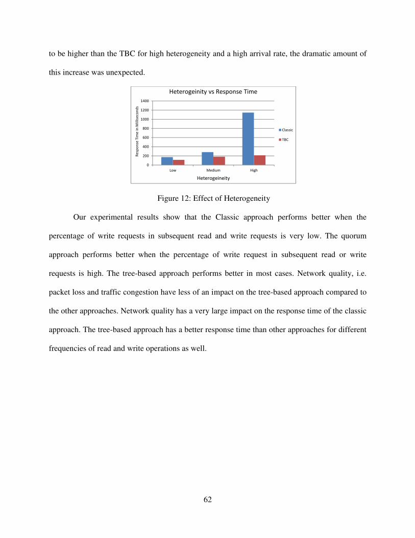
62
to be higher than the TBC for high heterogeneity and a high arrival rate, the dramatic amount of
this increase was unexpected.
Figure 12: Effect of Heterogeneity
Our experimental results show that the Classic approach performs better when the
percentage of write requests in subsequent read and write requests is very low. The quorum
approach performs better when the percentage of write request in subsequent read or write
requests is high. The tree-based approach performs better in most cases. Network quality, i.e.
packet loss and traffic congestion have less of an impact on the tree-based approach compared to
the other approaches. Network quality has a very large impact on the response time of the classic
approach. The tree-based approach has a better response time than other approaches for different
frequencies of read and write operations as well.
0
200
400
600
800
1000
1200
1400
Low Medium High
Re
spo
nse
Tim
e i
n M
illis
eco
nd
s
Heterogeineity
Heterogeinity vs Response Time
Classic
TBC

63
CHAPTER FIVE
TRANSACTION MANAGEMENT IN TBC
In airline reservations, banking, credit card processing, online retail purchasing, stock
markets, super market checkouts and many other applications, hundreds of concurrent users
execute database transactions. These applications typically rely on the ACID guarantees
provided by a database and they are fairly write-intensive. The main challenge to deploy
transactional data management applications on cloud computing platforms is to maintain the
ACID properties of Atomicity, Consistency, Isolation and Durability without compromising the
main feature of cloud platform scalability. However, suitable solutions are needed to deploy
transactional databases in a cloud platform. The maintenance of ACID properties is the primary
obstacle to the implementation of transactional cloud databases. The main features of cloud
computing: scalability, availability and reliability are achieved by sacrificing consistency. The
cost of consistency is one of the key issues in cloud transactional databases that must be
addressed. While different forms of consistent states have been introduced, they do not address
the needs of many database applications.
In Chapter 3, we presented the tree-based consistency approach that reduces
interdependency among replica servers to minimize the response time of cloud databases and to
maximize the performance of those applications. We explored different techniques of
maintaining consistency, such as the classic approach, the quorum approach and our tree-based
consistency approach. We identified the key controlling parameters of consistency maintenance

64
in cloud databases and studied the behavior of the different techniques with respect to those
parameters. Next, we describe how to implement transaction management and serializability for
the TBC approach, and compare its performance to the classic and quorum approaches.
5.1 Transactions
A transaction is a logical unit of work performed to access, and possibly update, several
data items within a database management system. Usually, transactions are initiated by user
programs. Those programs are normally written in a high-level language, such as an SQL data
manipulation-language or other programming languages. The main purposes of transactions are:
maintaining consistency within the database, handling database failure, and keeping isolation in
concurrent database access by multiple database operations. Usually, a transaction consists of
several read and/or write operations. Implementation of transaction processing can vary, because
different database management software implements transaction processing in their own
convenient and proprietary manner. Transactions in most database management software are
delimited with BEGIN_TRANSACTION and END_TRANSACTION statements, with multiple
database commands to execute in between these BEGIN and END statements.
According to the abstract transaction model [52], a transaction must be in one of the
following states: active, partially committed, failed, aborted or committed. Figure 13 shows the
state diagram of a transaction. The active state is the initial state. It indicates the corresponding
transaction is still executing its operations. If any unusual event occurs and normal execution of
the transaction is no longer possible, the transaction enters the failed state. A failed transaction is
rolled back and the database is restored to its state prior to the start of that transaction. The failed
transaction then enters the aborted state. Otherwise, after executing the final statement, a
transaction enters the partially committed state. If any unusual event occurs at the partially
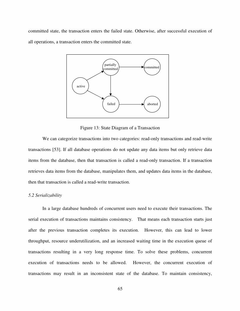
65
committed state, the transaction enters the failed state. Otherwise, after successful execution of
all operations, a transaction enters the committed state.
Figure 13: State Diagram of a Transaction
We can categorize transactions into two categories: read-only transactions and read-write
transactions [53]. If all database operations do not update any data items but only retrieve data
items from the database, then that transaction is called a read-only transaction. If a transaction
retrieves data items from the database, manipulates them, and updates data items in the database,
then that transaction is called a read-write transaction.
5.2 Serializability
In a large database hundreds of concurrent users need to execute their transactions. The
serial execution of transactions maintains consistency. That means each transaction starts just
after the previous transaction completes its execution. However, this can lead to lower
throughput, resource underutilization, and an increased waiting time in the execution queue of
transactions resulting in a very long response time. To solve these problems, concurrent
execution of transactions needs to be allowed. However, the concurrent execution of
transactions may result in an inconsistent state of the database. To maintain consistency,
active
partially
committed
failed aborted
committed

66
concurrent transactions must be scheduled to execute in such ways that the state of the database
remains the same as if all transactions are executed serially.
A schedule of transactions is a series of interleaved read and/or write operations to
various data items by different transactions. A schedule of transactions is equivalent to another
schedule of transactions if the conflicting operations in both schedules appear in the same order.
(Two database operations from two different transactions are said to conflict if they are trying to
access the same data item and at least one of the operations is a write operation.) If a concurrent
schedule of transactions is equivalent to some serial schedule of transactions, then the concurrent
schedule is serializable. Two major type of serializability exist [55]: i) conflict serializability and
ii) view serializability.
If any schedule of transactions can be transformed into another schedule of transactions
by a series of swapping (changing the order of) non-conflicting operations, and the conflicting
operations in both schedules are not swapped but appear in the same order, then the two
schedules are conflict equivalent. If any schedule of transactions is conflict equivalent to a serial
schedule of transactions, then that schedule is said to be conflict serializable.
Two schedules of transactions are said to be view equivalent if i) the initial value of each
data item required to execute the schedules is read by the same transaction in both schedules, ii)
each read operation reads the values written by the same transactions in both schedules and iii)
the final write operation on each data item is written by the same transactions in both schedules.
If a schedule of transactions is view equivalent to any serial schedule of those transactions, then
that schedule is view serializable. Conflict serializable is stricter than view serializable, and all
schedules that are conflict serializable are also view serializable.

67
5.3 Concurrency Control
When multiple transactions execute their operations concurrently in a database, the
chance of violating the Isolation and Consistency of the ACID properties is inevitable. To ensure
consistency and isolation within the database, the database system must control the interaction
between concurrent transactions. A variety of mechanisms are proposed to achieve this control,
which is known as concurrency control. Four of the most common concurrency control
mechanisms are: Locking, Timestamps, Multiversion and Optimistic [53].
Locking is the most popular technique to implement a concurrency control mechanism.
This technique is based on the idea of locking any data item a transaction will use. Before
starting execution, a transaction tries to acquire the locks of its required data items and the
transaction frees those locks after execution or after the transaction commits. A lock may not be
acquired if the lock has been allocated to another transaction. Usually a lock manager is
implemented within the system to keep track of and control access to the locks of the data items.
If any transaction fails to acquire locks on the required data items, it may wait until the locked
data items become free or restart after a certain amount of time as decided by some algorithm
implemented in the lock manager subsystem.
A variety of modes of locks are proposed to serve different conditions or reasons, the two
most renowned being: shared mode and exclusive mode. If any transaction obtains a shared
mode lock on a data item, then that transaction can only read that data item. As its name implies,
the transaction shares the lock with other transactions that are reading that data item. No write
operation on that data item is allowed by a transaction holding a shared mode lock. If a
transaction wants to write a data item, it must acquire an exclusive mode lock. As its name

68
implies, an exclusive mode lock can only be held by one transaction and no other transaction can
hold any other type of lock on that data item.
Timestamp ordering [53] is another popular technique for concurrency control
mechanisms. According to this technique, a schedule of transactions is serializable if it is
equivalent to a particular order that corresponds to the order of the transaction’s timestamp.
Conflicting operations must be executed in order of their timestamps. There are two timestamp
values associated with each and every data item in the database: a Read Timestamp and a Write
Timestamp. The Read Timestamp of a data item has the largest value of the timestamps of those
transactions who have successfully read that particular data item. The Write Timestamp of a data
item has the largest value of the timestamps of the transactions who have successfully written to
that particular data item. When any transaction tries to execute its operations, it may proceed,
wait or abort based on its timestamp and the timestamps of the of the data items required by that
transaction. A transaction can only read a data item if its timestamp is greater than or equal to
the Write Timestamp of the data item and a transaction can only write to a data item if its
timestamp is greater than or equal to the Read and Write Timestamps of the data item. If any
transaction needs to abort, it will be restarted later with a later timestamp.
Multiversion concurrency control [53] is based on keeping several older versions of data
items instead of overwriting data items with the most recent write operations. This technique is
very useful for mobile, temporal and real-time databases. Each write operation creates a new
version of the data item. Similar to timestamp ordering, there is a Read Timestamp and a Write
Timestamp associated with each version of every data item in the database. When a transaction
issues a read operation, the concurrency control manager chooses the appropriate version of a
data item to read to ensure serializability. The version chosen is based on the timestamp of the

69
transaction and the timestamp of the data item. The version chosen is the data item with the
largest Write Timestamp that is less than the timestamp of the transaction. This technique allows
transactions to read older versions of data items instead of aborting the transactions. When a
transaction needs to write an updated value, a new version of the data is created as long as the
version with the largest Write Timestamp, that is less than or equal to the timestamp of the
transaction, has a Read Timestamp less than or equal to the timestamp of the transaction.
Otherwise, the transaction must abort and restart with a later timestamp. The number of versions
of a data item depends on the database management systems requirement. This technique ensures
only view serializability, not conflict serializability.
The main difference between an optimistic concurrency control technique [53] and other
techniques is that it checks serializability violations after execution of transactions, whereas
other techniques check serializability violations during execution of transactions. The basic idea
of this technique is to execute all write operations of transactions on some local copy of the data
items, instead of the actual copy of the data items in the database. If serializability is not violated
by that transaction, then the transaction commits and the data items in the database are updated
from the local copies. Otherwise, the transaction is aborted and restarted after a certain amount
of time. According to this technique, every transaction is executed in three phases: i) Local
phase: Obtain copies of the data items from the database, store them locally, execute read and
write operation on those local copies, ii) Validation phase: check possible serializability
violations, iii) Write phase: write to the database from the local copies if the validation phase is
passed successfully, otherwise, restart the transaction after a certain amount of time.

70
5.4 Transaction Management in TBC
Due to the structure of the TBC system, we need different techniques from those
described above to process read-only and read-write transactions. As we previously discussed,
read and write operations are each handled by different servers. Moreover, transaction
management in cloud databases is different from that of a standalone database. It is more like
transaction management in a distributed database, where each node in the tree in TBC has a copy
of the database. According to earlier work [19, 39, 40] (as described in Chapter 3) the TBC
system has two parts: the controller and the replica servers. The controller plays an important
role in transaction management in the TBC system. We propose a combination of locking and
timestamp ordering to implement concurrency control in TBC. A hierarchical lock manager
manages the locks of the data items, and conflicting transactions either wait or restart, depending
on the timestamps of the transactions.
5.4.1 Read-Write Transactions in TBC
Read-write transactions are those transactions that need to fetch data items from the
databases and write the updated data item values to the database. As will be shown in Section
5.4.2, the execution plan of read-write transactions is different than those of read-only
transactions. A write-set of servers is needed to be engaged to perform read-write transactions.
The write-set of servers consists of the root node and its immediate children. As illustrated in
Figure 14, the successful execution of a read-write transaction needs the following steps:
1) In the first step, the user node sends a transaction initiation request to the controller. A
request receiver is deployed at the controller node that continuously listens on a specified
port at the controller node.

71
2) The controller takes the next sequence number from the transaction sequence number
pool for the requested transaction and assigns that sequence number to the transaction.
An incremental transaction sequence number is always assigned to the transactions based
on their arrival order on the controller node. The controller sends back to the user node
the following information: the root address and the transaction sequence number.
3) The user node prepares a transaction request with the assigned transaction sequence
number. Then the transaction request is sent to the root node.
4) After receiving the transaction requests from the user, the root node extracts the
following information from the transaction requests: the transaction sequence number
and the IDs of the required data items from the transaction. Lock requests for the required
data items are prepared at the finest possible granularity level, requiring a lock manager
with a hierarchical structure to be implemented in the system. There is only one lock
manager within the system. (A detailed description of the lock manager is discussed in
Section 5.5.) The root places the required lock requests on the lock request queue of the
lock manager.
5) Lock requests are submitted to the lock manager. If the requested locks are available,
then the lock manager assigns those locks to the transaction and updates a lock tree with
the transaction sequence number. The lock tree is a data structure used by the hierarchical
lock manager to keep track of the locks. If the requested locks are not available, the
transaction can either restart with the same transaction sequence number at a later time or
be placed into the waiting queue and wait for the occupied locks to be free. The decision
of the transaction's restart or wait is made based on the wait-die strategy [52]. Wait-die is
a deadlock avoidance strategy. According to this strategy, when any transaction tries to

72
acquire the lock of a data item which is already possessed by another transaction, then
either the acquiring transaction will wait for the lock to become free if it is older than the
transaction that holds the lock, or the acquiring transaction will die (abort and restart) if it
is younger than the transaction that holds the lock.
Figure 14: Read-Write Transaction Execution in TBC
6) After acquiring the required locks, the transaction manager launches a thread that is
responsible for executing the transaction. The root forwards the read-write transaction to
its immediate children, stores the transaction in the list of transactions to be executed and
waits for its children to reply.
7) After receiving the transaction request from the root node, an immediate child stores the
transaction request in the list of transactions to be executed and sends a successful reply
to the root node. The transaction request will remain in the list of transactions to execute
1. User sends transaction initiation request
to the controller
2. Controller sends back transaction
sequence number to user
3. User sends transaction request to the root
4. Required Lock request is submitted to
the lock manager
5. Lock Manager either accepts or rejects
the lock request
6. Root forwards transaction request to its
immediate children
7. Immediate children send reply to the
root node
8. Root initiates transaction commit
process and sends successful reply to user
9. Children of immediate children of root
synchronize updates with parent
periodically
User Program
Controller
Root
Lock Manager
Immediate Children
of Root
Version Manager
1 2
3 8
4
5
6 7
Other Children
9

73
until either a commit transaction or abort transaction message arrives. If the root sends a
commit transaction message, the transaction is executed on the actual database and
removed from the list. If the root sends an abort transaction message, the transaction is
simply removed from the list.
8) After receiving a successful reply from all immediate children, the transaction commit
process is started. The root removes the transaction from the list of transaction to be
executed, executes the transaction to the actual database, and broadcasts transaction
commit message to all its children. Then the thread associated with the transaction frees
all of its acquired locks. The transaction manager notifies the user node of a successful
completion of the transaction.
9) The children of the immediate children of the root node communicate with their parent
nodes periodically and start database synchronization, in which updates are synchronized
with the parents.
If any error or malfunction occurs during execution of the transaction, the transaction
manager sends an abort signal to the write-set nodes for that transaction. The rollback process
undoes all executed operations, waits for the immediate children's rollback completion
notification and then sets all acquired locks free. The immediate children of the root node only
convey committed transactions to their children. Therefore, it is not necessary to convey the
rollback process to the descendants of the immediate children of the root node. If any node stops
responding to requests, a failure recovery process is initiated by the controller node. (The failure
recovery process was discussed in Chapter 3.9)

74
5.4.2 Read-Only Transactions in TBC
Read-only transactions are those transactions that only fetch data items from the
databases; they do not need to update data items in the databases. The execution plan of read-
only transactions is simpler than that of read-write transactions. As there is no write operation in
read-only transactions, only read-set servers need to be engaged to execute read-only
transactions. According to the structure of the TBC system, any of the immediate children of the
root can participate as a node in the read-set of servers. As illustrated in Figure 15, a read-only
transaction requires the following steps to be executed:
1) The first step is the same as that of read-write transactions. The user node sends a
transaction initiation request to the controller.
Figure 15: Read-Only Transaction Execution in TBC
1. User sends transaction initiation
request to the controller
2. Controller sends back
transaction sequence number to
user
3. User send transaction request to
one of the immediate children of
the root
4. Immediate child begins read-
only transaction, communicates
with version manager
5. Immediate child checks with
version manager to ensure latest
version of data to be returned
6. Immediate child prepares query
results and sends back to the user
User Program
Controller
Root
Lock Manager
Immediate Child of
Root
Version Manager
1 2
3 6
5
4
Other Children

75
2) The controller takes the next sequence number from the transaction sequence number
pool, and assigns that sequence number to the transaction. The controller node also
selects one read server node for the read-only transaction from the immediate children of
the root node. The controller sends back to the user node the following information: the
read server address and the transaction sequence number.
3) The user node prepares the transaction request with the transaction sequence number and
then sends the transaction requests to one of the intermediate child of the root node.
4) The next step is slightly different than that of read-write transactions. After receiving a
transaction request from the user, the root extracts the following embedded information:
the transaction sequence number and the IDs of the required data items of the transaction.
Then the read server communicates with the version manager to obtain the most recently
committed version of each data item needed.
5) The read-server checks with the version manager to confirm the latest version of the data.
Every committed read-write transaction is kept in the list of transactions to execute in
durable storage until the read-write transaction is applied to the read-server’s database.
Hence, there is a time difference between the arrival of the transaction commit message
of a read-write transaction and the execution of that transaction on the read-server’s
database. For any read-only transaction executed, the version manager must use the latest
committed version of data. That means, if a read-only transaction requests a data item
that is updated by a committed transaction Ti whose updates have not been applied to the
read-server’s database yet, the version manager must replace the data items with latest
updated version from transaction Ti.

76
6) At this step a read-only transaction obtains the desired result, which is sent back to the
user node. As read-only transactions do not update any data items in the database, a
commit operation is not necessary for a read-only transaction.
If any error or malfunction occurred during execution of the transaction, the transaction
manager sends a message to abort the transaction. As stated previously, the rollback process is
not necessary, as read-only transactions do not make any changes to the database. Aborted
transactions will be restarted with the same sequence number after a certain amount of time. If
unresponsive behavior from any node is reported by other nodes at any time, the controller node
initiates the failure recovery process. (Details of the failure recovery process is described in
Chapter 3.9)
5.5 The Lock Manager in TBC
According to the structure of the TBC system, a huge number of delays are added to a
transaction’s execution due to the communication between the nodes over the network. A
transaction must hold the acquired locks until it commits. A longer duration of holding the lock
of a data item means a longer duration of unavailability of the data items. A large number of
transactions may restart or wait due to this unavailability of data items, which causes an
undesirably slow response time and very low throughput of the system. To increase the
availability of data items, we need to apply locks on the finest granularity levels possible. Sang et
al. [63] show that variable granularity levels employed by lock managers can help to increase
concurrent access to data items. However, implementation of locks at multiple levels of
granularity increases space and computational complexity. We decided to tradeoff between
granularity level and complexity. The levels of granularity used in the TBC system are a

77
database, table, column, and row. A transaction can lock the entire database, the entire table, the
entire column of a table, or an entire row as identified by key attributes.
There are two types of locks available at each level: a primary lock and a secondary lock.
If a transaction tries to access data items at any level, the primary lock of that level and the
secondary locks of the higher levels will be set to on. For example, if a transaction needs access
to an entire column, the lock manager locks the primary lock of that column and also locks the
secondary locks of the table containing that column and the database containing that table. No
other transaction will have access to that column or to the row level of that column. However, if
any transaction tries to access other columns, they will be successful, because the other columns
are not locked. If any transaction tries to lock the entire table containing that locked column, it
cannot. This is the main difference between a primary lock and a secondary lock. If a primary
lock is set at any level, the lock manager will not process any lock requests to that entity or lower
levels contained by that entity. If a secondary lock is set on at any level, the lock manager will
not process the requests for that entire level. If any other transactions are trying to access data
items at lower levels contained by that level while secondary lock of that level is on, the
transaction manager will process those requests. For example, if the secondary lock of a table is
on, no other transaction can lock the entire table, but they can lock other free columns. If the
primary lock of a table is on, the transaction manager will discard all requests to that table or
columns or rows of that table.
The Lock Manager in the TBC system is implemented in the root node. The Lock
Manager is an individual process dedicated to manage the locks of the data items of the database.
To implement locks on the finest granularity level, as mentioned previously, we utilize a
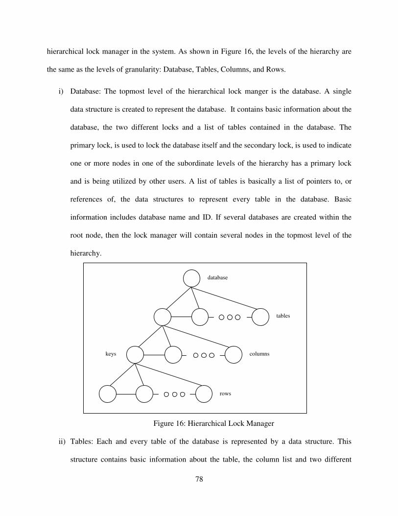
78
hierarchical lock manager in the system. As shown in Figure 16, the levels of the hierarchy are
the same as the levels of granularity: Database, Tables, Columns, and Rows.
i) Database: The topmost level of the hierarchical lock manger is the database. A single
data structure is created to represent the database. It contains basic information about the
database, the two different locks and a list of tables contained in the database. The
primary lock, is used to lock the database itself and the secondary lock, is used to indicate
one or more nodes in one of the subordinate levels of the hierarchy has a primary lock
and is being utilized by other users. A list of tables is basically a list of pointers to, or
references of, the data structures to represent every table in the database. Basic
information includes database name and ID. If several databases are created within the
root node, then the lock manager will contain several nodes in the topmost level of the
hierarchy.
Figure 16: Hierarchical Lock Manager
ii) Tables: Each and every table of the database is represented by a data structure. This
structure contains basic information about the table, the column list and two different
database
tables
columns
rows
keys

79
locks. A primary lock is used to lock the table itself and a secondary lock is used to
indicate one or more nodes in one of the subordinate levels of the hierarchy has a primary
lock and is being utilized by other users. The column list is a list of pointers to, or
reference of, a data structure to represent each and every column in the table.
iii) Columns: Each and every column of a table is represented by a data structure. This
structure contains basic information about columns, and also has two different locks.
Similar to the Database and Tables, a primary lock is used to lock the table itself and a
secondary locks is used when one or more nodes in one of the subordinate levels of the
hierarchy has a primary lock and is being utilized by other users. Columns representing
key attributes may contain two additional lists. One list, named the individual list, stores
the locked individual rows that are based on a hash function on that key attribute. A hash
function is used to save space and expedite search operations. Another list, named the
range list, is used if the lock request will affect multiple rows or a range of rows, in which
case that range is stored in the range list.
iv) Rows: There are two types of data structures designed to represent rows. One is for
individual rows and the other for ranges of rows. If users try to access a single row, then
an individual node is created with the key attribute values and that node is stored into the
individual list of the column representing that key attribute based on the hash function. If
users try to access a range of rows, a node is created with a specified boundary of the key
values, and that node is stored into the range list.
All of these data structures form a tree and several databases in the server form a forest.
A forest is formally defined as the union of several disjoint trees. Using the transaction
information, the appropriate tree is selected from the forest. The transaction manager extracts the

80
required data item information from the database commands. Then this information is passed to
the lock manager. The lock manager then analyzes the lock request and decides the granularity
levels for the requested locks. If a transaction will affect the entire database, such as an
administrative task, the lock manager will try to assign the lock to the database node of the lock
tree. If a transaction will affect an entire table, the lock manager will try to assign the lock to that
table. If a transaction will affect an entire column of a table, the lock manager will try to assign
the lock to that column. In most of the cases, a transaction will affect only a row. The lock
manager takes a look at the holding locks list, and if the row is available, the lock manager
proceeds and assigns the lock of that row to that transaction. If a transaction will affect multiple
rows, the lock manager tries to identify those rows by making a range of the key column. The
lock manager examines the holding range lock list, and if there is no conflict with other entries of
the list, a new lock request is assigned to that transaction.
5.6 Concurrency Control in TBC
Though the main concurrency control mechanism works at the root node, the controller
and immediate children of the root also take part in the concurrency control. The controller
assigns the sequence numbers to incoming transactions. Both locking and timestamp ordering
techniques are used to implement the concurrency mechanism in TBC system. The locking
technique described in the previous section is used to identify conflicting transactions
(transactions who are trying to access same data items) and control their access to data items.
The timestamp ordering technique is used to resolve some situations, such as deadlock. It is very
complicated and expensive to achieve time synchronization in a distributed system such as a
cloud. We use an alternate strategy, which is a centralized incremental counter instead of a
timestamp.

81
All user transactions communicate with the controller in the initial step of a transaction.
The controller assigns a unique sequence number to the transaction. A transaction possesses that
sequence number until it commits. A restarted transaction has the same sequence number as
before. The lock manager in the root node ensures that any two transactions never try to access
the same data items. Therefore, data sets that active transactions are trying to access are disjoint
at any time during execution. While concurrent execution of transactions is managed by the
multi-threading feature offered the by operating system, there is a dedicated thread engaged to
execute each transaction. Hence, as described in Section 5.4, the thread executes operations of a
transaction serially, meaning one by one.
5.7 Serializability in TBC
According to the definition of serializability, a schedule of transactions is serializable if it
is equivalent to some serial schedule. We emphasize that there can be many possible serial
schedules. As stated previously, in TBC, all incoming transaction requests are sent to the
controller node, where the controller assigns a unique transaction sequence number to every
transaction request incrementally. Read-write transactions are handled by the root node, where
transactions need to acquire locks of required data items before accessing that data. Only non-
conflicting transactions can proceed to execution. A dedicated thread is launched to execute
operations in read-write transactions one by one at the root node. A thread executes both read
and write operations within a transaction serially, while multiple threads execute multiple
transactions concurrently.
As described in Section 5.2, a schedule can be view serializable and/or conflict
serializable. To be view serializable a schedule needs to maintain three criteria: i) the initial
values of each data item used in that schedule must be read by the same transaction, ii) each read

82
operation must read the value written by the same transaction, iii) the final value of each data
item must be written by same transaction.
Hypothesis: TBC ensures view serializability of transactions.
Proof for read-write transactions: In TBC, a read-write transaction can proceed only if it
can acquire all the locks of the required data items. There is no chance that two transactions can
access same data item during execution even though both of them must access that data item,
since write locks in TBC always work in exclusive mode. Any conflicting operations in a
concurrent execution schedule will be in serial order. This satisfies all three criteria for view
serializability. Hence, it is always possible to find a serial execution schedule of transactions
that is equivalent to a concurrent execution in TBC.
Therefore, read-write transactions in TBC are view serializable.
Proof for read-only transactions: Read-only transactions are also executed by a dedicated
thread in the read-set servers. There is no lock mechanism implemented in the read-set servers,
because they always read committed versions of the data. A read-only transaction always
proceeds in the read-set servers. Since read-only transactions are executed serially at a read-set
server, they are always equivalent to some serial order and hence, satisfy both the first and
second criteria. The third criterion is not relevant since read-only transactions do not write data.
Therefore, read-only transactions in TBC are view serializable.
Proof for read-write and read-only transactions combined: Read-only transactions in
TBC do not affect the execution of read-write transactions; therefore, the execution of read-write
transactions in TBC remains view serializable. Likewise, read-write transactions do not affect
the execution of read-only transactions. Read-only transactions always read the most updated
version of the data written by a committed transaction that is available when the read-only

83
transaction begins execution. Versions created from newly committed transactions while a read-
only transaction is executing are not considered by the executing read-only transaction.
Therefore, transactions in TBC are view serializable.
Hypothesis: TBC ensures conflict serializability of transactions.
Proof for read-write transactions: Read-write transactions accessing the same data items
cannot proceed simultaneously, since all locks are exclusive and are obtained before execution
begins. Therefore, there are no conflicting operations in the execution, so the conflicting
operations are by default in serial order. It is always possible to convert the concurrent execution
schedule to a serial schedule by swapping the non-conflicting operations.
Therefore, read-write transactions in TBC are conflict serializable.
Proof for read-only transactions: Read-only transactions have only read operations, no
write or update operations. That means read-only transactions never conflict with other read-only
transactions. Threads in the read-set servers associated with read-only transactions execute read
operations within a transaction serially, but multiple read-only transactions read concurrently. It
is always possible to convert the concurrent execution of read-only transactions by swapping
read operations to a serial execution, since the read-only operations are non-conflicting.
Therefore, read-only transactions in TBC are conflict serializable.
Proof for read-write and read-only transactions combined: Read-only transactions in
TBC do not affect the execution of read-write transactions; therefore, the execution of read-write
transactions in TBC remains conflict serializable. Likewise, read-write transactions do not affect
the execution of read-only transactions. Read-only transactions always read the most updated
version of the data written by a committed transaction that is available when the read-only

84
transaction begins execution. Versions created from newly committed transactions while a read-
only transaction is executing are not considered by the executing read-only transaction.
Therefore, transactions in TBC are conflict serializable.
5.8 Common Isolation Level Problems
There are different levels of isolation used in the database industry: i) Read
Uncommitted, ii) Read Committed, iii) Repeatable Read, and iv) Serializable [52]. The read
uncommitted isolation level allows transactions to read a data item that was written by another
transaction that has not committed yet. The read committed isolation level requires a transaction
to only read data items that were written by a transaction that has committed. The repeatable read
isolation level requires a data item to return the same value when it is read more than once during
the same transaction. The serializable isolation level satisfies the definition of conflict
serializability. The isolation level option is usually specified by the database administrator or
designer. If a transaction is executed at a lower isolation level than serializability, then different
types of violations can occur. They are known as: i) Dirty Read, ii) Unrepeatable Read, and iii)
Dirty Write or Lost Update. Serializability is used as the isolation level in our TBC system. We
need to analyze TBC to ensure that there is no chance for an occurrence of these violations in our
system.
A dirty read violation occurs when a transaction reads the value of a data item that is
written by an uncommitted transaction. If that uncommitted transaction fails, then that written
value is no longer valid. However, some transaction may have read that invalid value and may
have used it in a calculation. In our system, a read-write transaction is executed in the root
server. In TBC, all locks needed for the transaction must be obtained before the transaction
begins execution, all locks are operated in exclusive mode and transactions hold their required

85
locks until they commit. As a result, there is absolutely no chance that a read-write transaction
reads the value of a data item that was written by an uncommitted transaction.
Read-only transactions are executed in the read-set servers and a lock manager exists in
the read-set servers. Only committed transactions are executed in the read-server after obtaining
confirmation from the root. If a committed transaction is not executed yet, the version manager
ensures that the query utilizes the latest committed values of the data items. As a result, the query
results always contain the value of a data item updated by a committed transaction. Hence, a
dirty read violation is prevented in the TBC system and a read-only transaction cannot read a
data item written by an uncommitted transaction.
An unrepeatable read can occur if a transaction reads a data item more than once during
its execution and in between the reads the data item is updated. This can occur when
transactions do not hold their required locks long enough, and some other transactions may
acquire those locks and change the data items. In our TBC system, read-write transactions are
only handled by the root and read-write transactions hold their required locks until they commit.
As a result, there is absolutely no chance that a read-write transaction can change the value of a
data item that is being using by another transaction. Hence, an unrepeatable read will never
occur in the TBC system, so repeatable read is satisfied.
Guaranteeing repeatable reads cannot guarantee against phantom reads, which can ensue
when new rows are appended to a table. A phantom read occurs when a transaction reads a set of
rows more than once and obtains a different answer each time, because additional rows have
been added to the table by a different transaction. Phantom reads cannot occur in TBC because
the entire table will be locked when rows are added to the table.

86
Related to the concept of repeatable reads is that of a dirty write (or lost update), which
can occur when two concurrent transactions read the same value of a data item, and both
transactions update the data item. Because one of those transactions must update the data item
before the other, the effect of the earlier update operation will be lost, as the later update
transaction overwrites the value written by the earlier update transaction. However, a problem
exists because the later update transaction should have read the value written by the earlier
update transaction. Therefore, the value written by the earlier update transaction is lost forever,
which is why this situation is called the lost update problem. In the TBC system, two transactions
never have access to the same data items at the same time. The later transaction must wait to read
the data item until the earlier transaction updates the data item and releases its locks. As a result,
the lost update violation will never occur in the TBC system.
TBC does not experience dirty reads, unrepeatable reads or dirty writes. Therefore, TBC
ensures an isolation level of serializability.
5.9 Preserving the ACID properties
Atomicity means either all of the operations of a transaction are completed successfully or
none of them. If anything goes wrong during execution of a read-write transaction, the root node
initiates the rollback process. The rollback process undoes all write operations from the database
of the root, conveys a rollback messages to its intermediate children and waits for its children's
rollback process completion. Read-only transactions never issue any write operations, so no roll
back process is required for a read-only transaction. Moreover, when something goes wrong
during execution of a read-only transaction, that transaction is restated. That means all operations
are discarded, so the atomicity property is preserved in the TBC system.

87
Consistency means a consistent database remains consistent after execution of every
transaction. A read-write transaction needs participation of the write-set servers to be executed.
A read-write transaction execution is initiated from the root node, where the lock manager is
implemented. The lock manager ensures that after executing read-write transactions, the database
is always consistent. A read-only transaction is performed by the immediate children of the root,
and the immediate children's database is always consistent with that of the root. Though
propagation of write operations from intermediate children to other nodes requires more time,
those servers never participate in transaction execution. As defined by apparent consistency, as
described in Chapter 3.10, since users only read/write to the root or its immediate children, the
system always remains consistent to user.
Isolation means the impact of a transaction on a data item cannot be altered by another
transaction’s access to the same data item. In TBC, a read-write operation is sent to the root. The
lock manager is implemented in the root node. Before execution starts, every transaction needs to
acquire locks on its required data items; otherwise, they cannot proceed to execution. Once a
transaction acquires its required locks they execute their operations, so no other transaction can
acquire those locks. They have to wait until the lock possessing transaction commits and releases
those locks. The root waits for its intermediate children's completion of a write operation to
proceed with the next write operation. There is no way that a transaction can alter the effect of
another transaction. Therefore, the isolation property is preserved.
Durability means the impact of a committed transaction would not be undone in case of a
database failure. The list of update operations from committed transactions, not applied to the
database yet, is stored in permanent storage. This allows for recovery in the event of a failure.
In addition, there are several servers in the system, which also maintain copies of all committed

88
data. There is absolutely no chance of data loss of a committed transaction in case of database
failure. Therefore, durability is also preserved.
In this chapter we have described transaction management in TBC. We have specified
the steps necessary for processing read-write and read-only transactions in TBC. The
hierarchical lock manager and concurrency control were also presented. We discussed how TBC
guarantees the ACID properties, avoids isolation problems and we proved that TBC is
serializable. In the next chapter we examine the performance of TBC transaction management.

89
CHAPTER SIX
PERFORMANCE ANALYSIS OF THE TRANSACTION MANAGEMENT SYSTEM
A DBMS (DataBase Management System) faces a large number of challenges to process
transactions. Processing transactions requires maintaining the ACID properties while ensuring an
acceptable throughput and response time of the system. Different DBMSs use different
techniques to face those challenges. The challenges of a centralized DBMS are also different
from the challenges of a distributed DBMS. In a distributed system, data can be replicated over
a wide area, requiring different approaches to maintain ACID properties. In the era of cloud
computing, as entrepreneurs move or consider moving their IT sections to third party clouds, the
different challenges for DBMSs associated with processing transactions in a cloud must be
addressed. The elastic workload, geographical distance between database servers,
communication over a wide area network, response time, resource utilization, and Service Level
Agreements (SLAs) present new forms of challenges for DBMSs in a cloud platform. In this
chapter we explore different aspects of DBMSs using different consistency approaches for
different environments and conditions in a cloud. A separate simulation program is developed to
implement a DBMS using one of three consistency techniques. We study the effect on the
performance of the database of the workload, the read/write transaction ratio, the probability
distribution of the requested data items by transactions, and the number of tables. The
performance of the database is measured by response time and restart ratio.
90
6.1 Transaction Manager for Different Consistency Approaches
To conduct our study and a performance analysis of our proposed TBC approach, we also
consider the two other popular consistency approaches, the classic approach and the quorum
approach, for maintaining consistency in a transaction management system on a cloud platform.
We use a generalized layered architecture to implement a common platform for a transaction
management system using the different consistency approaches. Figure 17 shows the layers of
the architecture. Implementation of the layers and inter layer communication vary with each of
the three consistency approaches.
In the topmost layer is a user program developed to produce transaction requests
periodically. Different probability distribution functions are used to produce a realistic workload
to simulate user requests in the real world. In the second layer, a gateway program was
developed in the controller node. The gateway program assigns transaction sequence numbers
based on the arrival order of the transaction requests in the controller node. Different programs
were developed in the third layer specific to each particular consistency approach. For the classic
approach, a program was developed to act as the primary server in the third layer. For the
quorum approach, a program was developed to serve as the coordinator of the quorum voting
during transaction execution in the third layer. For the TBC approach, a program was developed
to serve as the root in the TBC system at the third layer. All of these programs serve the same
purpose, to extract the information of the required data items from the transaction requests and
then forward the lock requests to the lock manager.
The implementation of a lock manager also depends on the particular consistency
approaches. A hierarchical tree-based lock manager is implemented for the TBC approach, while
a two dimensional lock table is implemented for both the classic and quorum approaches. The

91
next layer of the architecture is the replica servers. The interconnection between the replica
servers also depends on the specific consistency approach. Replica servers are connected
according to a consistency tree for the TBC approach. In the classic approach all of the
secondary servers are directly connected to the primary server. All the replica servers are
interconnected to each other in the quorum approach. The bottom layer of the architecture is the
version manager. The version manager is implemented to prevent the dirty read problem. It
manages the values of those data items that are updated by uncommitted transactions.
Figure 17: Layered Architecture of Transaction Management System
In Chapter 5 we categorized transactions into two categories: read-only transactions and
read-write transactions. Execution of a read-only transaction is different from a read-write
transaction for each of the three consistency approaches. A detailed description of transaction
execution for both read-write and read-only transactions is given in the following subsections.
6.1.1 Transaction Execution in the Classic Approach
As we previously discussed in chapter 6.1, in the classic approach a data value is not
returned for a read or a write operation until all replica copies can return the same value. That
means the primary server will wait to complete a read-write transaction until all of the secondary
servers complete that transaction. According to the previously discussed consistency relation
(W+R > N), any of the secondary servers can complete a read-only transaction by itself.
User Program
Controller
Primary Server / Root / Coordinator
Lock Manager
Secondary Server / Children / Participant
Version Manager

92
Figure 18 illustrates the classic approach, assuming six replicas reside at six different
nodes in the network. One of the six nodes is designated as the primary node. As shown in
Figure 18(a), it will take the first eight steps (described earlier in Chapter 5.4.1) to complete
execution of a read-write transaction, with the primary node taking the place of the root. Only
steps six and seven are slightly different. In step 6, the primary server will forward the read-write
transaction request to all of the secondary servers. In step 7, the primary server will wait until all
of the secondary servers complete their execution. Also, there is no step 9, since all nodes have
already been informed of the read-write transaction. As also shown in Figure 18(b), read-only
transaction execution requires the same six steps to complete (described earlier in chapter 5.4.2),
with a secondary server taking the place of an immediate child node.
(a) Read-Write Transaction (b) Read-Only Transaction
Figure 18: Transaction Execution in the Classic Approach
Controller User
Primary
Secondary
Version Manager
1
2
3
4
5
6
Controller User
Primary
Secondary
Lock Manager
1
2
3
4
5
6
7
8

93
6.1.2 Transaction Execution in the Quorum Approach
As we discussed in chapter 4.2, a quorum-based consistency system requires more than
half of the replicas to complete a read or write operation before the data is available for a
subsequent read or write. There are no specific primary or secondary replicas in quorum-based
systems. Any of the servers can serve as the coordinator while the other servers serve as
participants. The coordinator receives a transaction request, takes the necessary initiatives, like
acquiring locks, and then coordinates with the other participants to execute that transaction. The
participants only respond to the coordinator's requests.
As shown in Figure 19(a), a read-write transaction request is received by the coordinator.
The eight steps are similar to those for the classic approach in Figure 18(a), except for step 7. In
this step, the coordinator waits until a majority of the participants execute the read-write
transaction instead of waiting for all of the participants to execute the read-write transaction.
Figure 19(b) illustrates the steps taken when a read-only transaction request is received by the
coordinator. Instead of six steps for a read-only transaction, there are eight steps. In steps 4 and
5 it is the coordinator that determines the appropriate version before sending a request to a
participant. The coordinator checks with the version manager to confirm whether or not the
result contains any dirty values. In step 6, the coordinator then sends the read transaction
requests to all participants. Similar to a read-write transaction, in step 7 the coordinator waits
until a majority of the participants reply with the same committed version of the data before it
notifies the user of a successful read-only transaction in step 8.
6.1.3 Transaction Execution in TBC
As we discussed in chapter 3, a tree defines the path that will be used by the replica nodes
to communicate with each other to propagate the update requests in the tree-based consistency
Children

94
approach. As shown in Figure 20(a), to process a read-write transaction request, it requires the
same nine steps described in chapter 5.4.1. As also shown in Figure 20(b), to execute a read-only
transaction the same six steps described in chapter 5.4.2 are required.
(a) Read-Write Transaction (b) Read-Only Transaction
Figure 19: Transaction Execution in the Quorum Approach
6.2 Experiment Environment
We designed the experiments to compare the transaction execution performance of the
classic, quorum and TBC approaches. We have performed our experiments on the Sage cluster,
which is a green prototype cluster that we have built at the University of Alabama. Our Sage
cluster currently consists of 10 nodes, where each node is composed of Intel D201GLY2
mainboard with 1.2 GHz Celeron CPU, 1 Gb 533 Mhz RAM, and 80 Gb SATA 3 hard drive.
The cluster nodes are connected to a central switch on a 100 Megabit Ethernet in a star
configuration, using the D201GLY2 motherboard on-board a 10/100 Mbps LAN. The operating
Controller User
Coordinator
Participator
1
2
3
4
5
6
7
8
Controller User
Coordinator
Participator
Version Manager
1
2
3
4
5
6
7
8 Lock Manager

95
system is Ubuntu Linux 11.0 server edition. Shared memory is implemented through NFS
mounting of the head node's home directory. The Java 1.6 platform was used to run our
simulation program written in Java. MySQL Server (version 5.1.54) was set up on each node to
implement the database replicas.
(a) Read-Write Transaction (b) Read-Only Transaction
Figure 20: Transaction Execution in the TBC Approach
6.3 Experiment Design
Nodes of the clusters are used to deploy the cloud database. The user program, controller,
and database servers are implemented in individual nodes. A program is developed to produce a
real-time workload (transaction request) to the database servers. An arrival of a transaction
request is controlled by a Poisson distribution function. In other words, a user program generates
transaction requests after a certain amount of time and the interval between the arrivals of two
consecutive transaction requests satisfies the Poisson distribution function. A dedicated thread is
invoked to produce transaction requests. We call this thread the transaction thread. At first, the
Controller User
Root
Children
Controller User
Root
Children
Lock Manager
Version Manager
1
2
3
4
5
6
7
8
9
1
2
3 6
4
5

96
transaction thread communicates with the controller to obtain the transaction sequence number.
A receiver program is developed to receive the transaction requests at the controller end. The
controller assigns a consecutive transaction sequence number based on the arrival of the
transaction request, and sends it back to the transaction thread at the user node. The transaction
thread assigns the transaction request as either a read-only or a read-write transaction by using a
uniform distribution function. Another uniform distribution function determines the number of
database operations that a transaction request may have. If the transaction request is read-write,
then whether each operation of the transaction is either a read operation or a write operation is
decided by another uniform distribution function. A read-only transaction request consists of
only read operations. How many tables to be used are determined by another uniform
distribution function. Which tables and columns are going to be used by the operation are
selected by a ZipF distribution function. When all these decisions are made, the transaction
thread prepares a transaction request with the described information.
The transaction thread invokes another thread to send the transaction request to the
controller over the network. Network parameters are determined in the same fashion as described
in chapter 4. Another simulation program is developed to manage the transaction request at the
primary server, root or coordinator end. A receiver is deployed to listen at the network port to
receive transaction requests. An individual thread is invoked to manage the transaction request at
the server end. The server extracts the required data item information and prepares the lock
requests for those data items. The lock manager is an individual thread that is running on the
same server. The lock manager either grants the locks if they do not conflict with any existing
locks or the lock manager rejects the lock requests if at least one of the lock requests from the
transaction conflicts with an existing lock. Transactions with rejected lock requests may wait or

97
restart with the same transaction sequence number. Restarted transactions are sent back to the
user node and the user program will regenerate the transaction request with the same sequence
number. Waiting transactions are forced to sleep and are awakened periodically to check the
availability of the required locks. Transactions granted locks proceed to execution. In all three
approaches, the server forwards granted transaction requests to its subordinate servers.
Operations of the transaction are executed one by one at a subordinate server. In order to commit
the transaction, the server will wait for all secondary servers to reply in the classic approach, all
immediate children to reply in the TBC approach, and the majority of the participants to reply in
the quorum approach. Lastly, the thread sends a transaction completion notification to the user
node.
Table 3 shows the default values used in the experiments. The request arrival rate λ is the
arrival unit time specifying the possibility of a request arrival every 10 ms period. The default
value of λ is 0.15, meaning there is a 15% chance a request will arrive every 10 ms. The read-
only and read-write transaction request ratio is 70%-30%, meaning there is a 70% chance a
transaction request is a read-only request and a 30% chance a transaction request is a read-write
request. The Read/Write ratio in a Read-Write transaction request is 30%-70%. That means in a
read-write transaction request, 30% of the operations are read operations and 70% of the
operations are write operations. The table id and column id of a required data item is selected by
a ZipF distribution function with 1.01 skewness parameter. The reason we chose 1.01 as the
skewness parameter is because the skewness of word selection in human language is very close
to 1 [56]. There are 25 tables in the database and the maximum number of columns that a table
can have is 15. A uniform distribution function selects the length of a transaction request

98
between 2 to 8 operations. Another uniform distribution function selects between 1 and 5 number
of tables to be used in a transaction.
Table 3: Default Parameters in Transaction Execution
Parameter Name Default value
Request Arrival Rate λ .15
Arrival Unit Time 10 ms
Read-only/Read-Write Ratio 70%-30%
Read/Write Operation Ratio
(In Read-Write Transaction)
30%-70%
Tables Selection Skewness 1.01
Columns Selection Skewness 1.01
Number of Tables 25
Number of Columns 15
Operations in a Transaction 2-8
Relations used in a Operation 1-5
We take two measurements from the experiments: response time and restart percentage.
Response time is measured as the time difference between a transaction request transmission and
receiving the response to that request. The restart percentage is how many transactions need to be
restarted during execution per 100 transactions. One thousand transaction requests are generated
in every experiment. We conduct each and every experiment multiple times and take the average
from those runs of the experiments.
6.4 Effect of the Transaction Request Rate
The first experiment tests the effect on the response time and restart ratio for different
arrival rates of transaction requests by changing the value of λ. Figure 21 illustrates the results

99
when the arrival rate increases from 0.05 to 0.25. A λ of 0.05 means every 10 ms, there is a 5%
chance a request will arrive, and a λ of 0.25 means there is a 25% chance a request will arrive
every 10 ms.
The remaining values used in this experiment are the default values appearing in Table 3.
The x-axis of the graphs in Figure 21 represent the different values of λ and the y-axis of the
graphs in Figure 21(a-c) represent the response time in milliseconds and in Figure 21(d) it
represents the percentage of restarted transactions during execution. The blue bar indicates the
elapsed time or the percentage of restarted transactions for the classic approach, the red bar
represents the elapsed time or the percentage of restarted transactions for the quorum approach
and the green bar represents the elapsed time or the percentage of restarted transactions for the
tree-based approach. Figure 21(a) shows the results for read-only transaction requests, Figure
21(b) shows the results for read-write transaction requests, Figure 21(c) shows the results for
both read-only and read-write transaction requests combined, and Figure 21(d) shows the
percentage of restarted transactions during execution. In Figure 21, the response time and the
restart percentage both increase as the request arrival rate increases from 0.05 to 0.25 for all three
approaches.
As shown in Figure 21(a), the response time of the quorum approach increases more than
that of the classic and TBC approaches as the arrival rate increases. In the execution of read-
only transactions, the average response time of the classic approach varies little from 96 ms for λ
= 0.05 to 105 ms for λ = 0.25, the quorum approach varies dramatically from 232 ms for λ = 0.05
to 423 ms for λ = 0.25 and the TBC approach varies from 84 ms for λ = 0.05 to 99 ms for λ =
0.25. Communication delays and multiple node dependencies are the main causes behind the
highly growing response time in the quorum read-only transactions. Multiple servers have to

100
participate in the quorum approach whereas only one server is involved in both the classic and
the TBC approaches. Both the classic and TBC read response time is nearly stable with the main
reason being only one server is involved.
(a) Read-Only Requests (b) Read-Write Requests
(c) Combined Requests (d) Restart Percentage
Figure 21: Effect of Transaction Request Rate
Figure 21(b) shows the read-write transaction response time with respect to arrival rate.
In the execution of read-write transactions, the average response time of the classic approach
Re
spo
nse
Tim
e (
Mill
ise
con
d)
Arrival Rate
Arrival Rate Vs Response Time (Read-Only)
Classic
Quorum
TBC
Re
spo
nse
Tim
e (
Mill
ise
con
d)
Arrival Rate
Arrival Rate Vs Response Time (Read-Write)
Classic
Quorum
TBC
Re
spo
nse
Tim
e (
Mill
ise
con
d)
Arrival Rate
Arrival Rate Vs Response Time
Classic
Quorum
TBC
Re
sta
rt %
Arrival Rate
Arrival Rate Vs Restart %
Classic
Quorum
TBC

101
increases from 235 ms for λ = 0.05 to 803 ms for λ = 0.25, the quorum approach increases from
225 ms for λ = 0.05 to 665 ms for λ = 0.25, while the TBC approach varies little from 166 ms for
λ = 0.05 to 233 ms for λ = 0.25. Both the classic and quorum approaches are affected by the
higher arrival rate. The effect of the higher arrival rate on the classic approach is greater than on
the quorum approach. This is because in the classic approach, the primary server waits for all of
the secondary servers to complete their execution for every single read-write transaction,
whereas in the quorum approach, the coordinator waits for the majority of the participants to
finish the transaction. The effect of the higher arrival rate on a TBC read-write transaction
execution is very small. This is because the interdependency between nodes is minimized in the
TBC approach. Less interdependency between nodes makes TBC less affected by a higher
arrival rate.
In figure 21(c) the combined results for read-only and read-write transactions are shown.
In execution of both read-only and read-write transactions combined, the average response time
of the classic approach varies from 137 ms for λ = 0.05 to 314 ms for λ = 0.25, the quorum
approach increases the most from 229 ms for λ = 0.05 to 495 ms for λ = 0.25 and the TBC
approach increases the least from 108 ms for λ = 0.05 to 139 ms for λ = 0.25. Performance of the
quorum approach is worse than the others because of its higher response time in execution of
read-only transactions. Performance of the TBC approach is better than the other two
approaches.
Figure 21(d) shows the restarted transaction percentage with respect to transaction arrival
rate. Only a read-write transaction can be restarted if it is trying to access locked data items. The
average transaction restart percentage of the classic approach increases from 0.9% for λ = 0.05 to
30.5% for λ = 0.25, the quorum approach increases from 0.7% ms for λ = 0.05 to 14.6% for λ =

102
0.25 and the TBC approach increases from 1% for λ = 0.05 to 8.3% for λ = 0.25 in the execution
of transactions. Classic has the highest restarted transaction percentage than the others at higher
arrival rates. The classic approach also has a higher response time in execution of read-write
transactions at the arrival rates of 0.2 and 0.25. TBC has slightly higher restart ratio at the lower
arrival rates of 0.05 to 0.15 than both the classic and quorum approaches. TBC also has a higher
restart ratio at 0.20 than quorum. Despite a higher restart ratio, the response time for TBC is
faster than for the classic and quorum approaches. This is because it takes less time to process a
transaction with TBC and only 1 – 1.2% of the transactions are restarted. TBC has a
significantly lower transaction restart ratio with respect to other approaches at the highest arrival
rate. This is because the interdependency minimized by TBC is most notable at higher arrival
rates.
Our experiments show that our proposed TBC approach has a better response time than
the classic and quorum approaches, even as the arrival rate increases and the system becomes
more heavily loaded.
6.5 Effect of the Read-Only/Read-Write Transaction Request Ratio
The read-only and read-write transaction request ratio can vary from application to
application. While a traditional data management application typically has a 70%-30% read-
write ratio [38], it is also important to consider applications with different read-only/read-write
request ratios. The behavior of read-only applications and read-write applications are different.
In this experiment we study the effect on both the response time and the percentage of restarted
transactions for the three consistency approaches as the percentage of read-only versus read-
write transaction requests increases.

103
Figure 22(a) shows the results for read-only transaction requests, Figure 22(b) shows the
results for read-write transaction requests, Figure 22(c) shows the results for both read-only and
read-write transaction requests combined, and Figure 22(d) shows the percentage of restarted
transactions during execution. A constant arrival rate λ=0.15 is maintained for this experiment.
The x-axis of the graph represents different ratios of read-only and read-write transaction
requests. The ratio 90-10 is considered as a read intensive application and the ratio 50-50 is
considered as a write intensive application. The y-axis of the graphs in Figures 22(a-c) represent
elapsed time in milliseconds and the y-axis of the graph in figures 22(d) represent the transaction
restart percentage. In Figure 22, the blue bar indicates the elapsed time or the percentage of
restarted transactions of the classic approach, the red bar represents the elapsed time or the
percentage of restarted transactions of the quorum approach and the green bar represents the
elapsed time or the percentage of restarted transactions of the TBC approach.
Figure 22(a) shows the effect of the read-write ratio on the response time of the read-only
transactions. For the execution of read-only transactions, the average response time of the classic
approach varies from 97 ms for the 90-10 ratio to 109 ms for the 50-50 ratio, the quorum
approach varies from 263 ms for 90-10 to 292 ms for 50-50 and the TBC approach varies from
84 ms for the 90-10 ratio to 102 ms for 50-50 ratio. The response time for read-only transactions
was expected to decrease for all three approaches as the read-only/read-write ratio decreased.
However, in Figure 22(a), the response time of read-only transactions gradually increases with a
lower percentage of read-only transactions for the classic and TBC approaches. This can be
explained as follows. A lower read-only/read-write ratio has a smaller percentage of read-only
transactions and a higher percentage of read-write transactions, resulting in lower amount of
workload to the read-servers. However, every member of the read-set servers is also a member

104
of the write-set servers in the classic and TBC approaches. The execution of a read-write
transaction execution requires involvement of every read-server too. For the 90-10 ratio, the
execution of 90% read-only transactions is shared by multiple read-servers and the execution of
10% of read-write transactions requires involvement of every read-server. The same is true for a
50-50 ratio, the execution of 50% read-only transactions is shared by multiple read-servers and
the execution of 50% read-write transactions requires the involvement of every read-server.
Hence, the workload with a lower percentage of read-only transactions is greater than with a
higher percentage of read-only transaction in the classic and TBC approaches. This explains why
the response time of read-only transactions increases as the percentage of read-only transactions
decreases in the classic and TBC approaches.
The execution of read-only transactions in quorum requires the involvement of multiple
servers for each read request. At a lower percentage of read-only transactions, the quorum read-
server has a smaller workload than that at a higher percentage of read-only transactions.
However, despite this decrease in workload, the response time of the quorum approach remains
much higher than that of the classic and TBC approaches even at the 50-50 ratio.
Figure 22(b) shows the effect of the read-only/read-write ratio on the execution of read-
write transactions. An increase in the number of read-write transactions does have an impact on
the response time of the read-write transactions. The response time increases as the read-
only/read-write ratio decreases for all three approaches. For the execution of read-write
transactions, the average response time of the classic approach increases from 239 ms for the 90-
10 ratio to 1104 ms for the 50-50, the quorum approach increases from 227 ms for the 90-10
ratio to 1248 ms for the 50-50 and the TBC approach increases from 168 ms for the 90-10 ratio
to 280 ms for the 50-50 ratio in the execution of read-write transactions. The average response

105
time increases most dramatically with a higher read-write transaction percentage. Quorum has
the worst response time at the 50-50 ratio. Both quorum read-only and read-write transaction
execution requires involvement of multiple servers. Therefore, the workload for the servers is
higher in the quorum approach. Similarly, the classic approach requires all of its servers to
participate in a write operation. That is why the classic and quorum approaches take more time
in the execution of read-write transactions, and the average response time for read-write
transactions is higher in the quorum and classic approaches. TBC has a notably better response
time in the execution of read-write transactions.
Figure 22(c) shows the overall effect of the read-only/read-write ratio on the execution of
both read-only and read-write transactions. The average response time of the classic approach
increases from 139 ms for the 90-10 ratio to 407 ms for 50-50, the quorum approach increases
from 252 ms for the 90-10 ratio to 578 ms for 50-50 and the TBC approach increases from 109
ms for the 90-10 ratio to 155 ms for the 50-50 ratio in execution of read-only and read-write
transactions. As the read-write transactions have more effect on servers than read-only
transactions, the average response time is increased with a higher read-write transaction
percentage. Quorum has the worst response as it imposes more interdependency between servers
in execution of both read-only and read-write transactions. TBC has better response time than the
others as interdependency is carefully reduced.
Figure 22(d) shows the effect of the read-only/read-write ratio on the transaction restart
percentage. For the execution of read-only/read-write transactions, the percentage of restarted
transactions of the classic approach increases from 0.3% for the 90-10 ratio to 68.8% for the 50-
50 ratio, the quorum approach increases from 0.1% for the 90-10 ratio to 67% for the 50-50 and
the TBC approach increases from 0.6% for the 90-10 ratio to 20.2% for the 50-50 ratio. Every

106
approach has a noticeably low restart percentage at the lower read-write transaction percentages.
The classic and quorum approaches have a significantly higher restart percentage at higher read-
write transaction percentages compared to TBC. TBC has the best performance, with a restart
percentage one third of the classic and quorum approaches.
(a) Read-Only Requests (b) Read-Write Requests
(c) Combined Requests (d) Restart Percentage
Figure 22: Effect of Read-Only/Read-Write Transaction Request Ratio
Re
spo
nse
Tim
e (
Mill
ise
con
d)
Read-Only/Read-Write Ratio
Read/Write Ratio Vs Response Time (Read-Only)
Classic
Quorum
TBC
Re
spo
nse
Tim
e(M
illis
eco
nd
)
Read-Only/Read-Write Ratio
Read/Write Ratio Vs Response Time (Read-Write)
Classic
Quorum
TBC
Re
spo
nse
Tim
e(M
illis
eco
nd)
Read-Only/Read-Write Ratio
Read/Write Ratio Vs Response Time
Classic
Quorum
TBC
Re
sta
rt %
Read-Only/Read-Write Ratio
Read/Write Ratio Vs Restart %
Classic
Quorum
TBC

107
Our experiments have shown that changes in the read-only/read-write ratio will have less
of an effect on the response time and restart ratio of TBC than the other approaches. TBC has
notably better performance at higher workloads than the classic and quorum approaches, as a
higher read-write percentage imposes a higher workload, which is best handled by TBC.
6.6 Effect of the Selection Skewness Parameter
If a list is made of several items and they are ranked on the basis of their frequency of
being selected, then according to the ZipF distribution, the most frequently selected item is
selected twice as many times as the second most selected item. The skewness parameter is the
value of the exponent characterization of the ZipF distribution. A higher value of skewness
shrinks the selection of items chosen from the first ranks of the list. This means a fewer number
of items are selected from the ranks most of the time. A lower value of skewness extends the
selection of items downward through the ranks of the list. This means the probability of an item
at the bottom of the list being selected is increased. A data item can be identified by a table id, a
column id, and a row id. The selection process of each table or column is with the ZipF
distribution. In this experiment, we vary the skewness parameter from the lowest value of 0.0001
to the highest value of 10000. We study the effect of the skewness parameter on both the
response time and the percentage of restarted transactions for the three consistency approaches.
The x-axis of the graphs in Figure 23 represents the different values of the skewness
parameter of the ZipF distribution. The y-axis of the graphs in Figures 23(a-c) represents the
response time in milliseconds and in Figure 23(d) it represents the percentage of restarted
transactions during execution. The blue bar indicates the elapsed time or the percentage of
restarted transactions of the classic approach, the red bar represents the elapsed time or the
percentage of restarted transactions of the quorum approach and the green bar represents the

108
elapsed time or the percentage of restarted transactions of the tree-based approach. Figure 23(a)
shows the results for read-only transaction requests, Figure 23(b) shows the results for the read-
write transaction requests, Figure 23(c) shows the results for both read-only and read-write
transaction requests combined, and Figure 23(d) shows the percentage of restarted transactions
during execution.
Figure 23(a) shows the effect of data selection skewness on the response time for the
execution of read-only transactions. The average response time of the classic approach varies
from 100 ms to 104 ms, the quorum approach varies from 282 ms to 289 ms and the TBC
approach varies from 90 ms to 94 ms in the execution of read-only transactions. The average
response time remains almost the same for all three approaches with respect to different selection
skewness parameters. This means selection skewness does not have any effect on the response
time in the execution of read-only transactions. Quorum has a noticeably higher response time
than both the classic and TBC approaches because multiple servers are needed to complete a
read-only transaction in the quorum approach. The response time of TBC is slightly better than
the classic approach.
Figure 23(b) shows the effect of data selection skewness on the response time in the
execution of read-write transactions. The average response time of the classic approach varies
from 304 ms to 315 ms, the quorum approach varies from 310 ms to 318 ms and the TBC
approach varies from 192 ms to 196 in the execution of read-write transactions. The average
response time again remains almost same for all three approaches with respect to different
selection skewness parameters. That means selection skewness does not have any effect on the
response time in the execution of read-write transactions. As expected, the response time of TBC
is notably better than both the classic and quorum approaches.

109
0
1
2
3
4
5
6
0.0001 0.01 1.01 100.01 10000.01
Re
sta
rt %
Skewness (Relation & Column)
Skewness Vs Restart %
Classic
Quorum
TBC
(a) Read-Only Requests (b) Read-Write Requests
(c) Combined Requests (d) Restart Percentage
Figure 23: Effect of the Selection Skewness Parameter
Figure 23(c) shows the effect of data selection skewness on the response time in the
execution of both read-only and read-write transactions combined. The average response time of
the classic approach varies from 156 ms to 161 ms, the quorum approach varies from 291 ms to
295 ms and the TBC approach varies from 118 ms to 121 ms in the execution of read-write
transactions. The average response time remains almost the same for the classic, quorum and
TBC approaches as the selection skewness parameter increases. This means selection skewness
Re
spo
nse
Tim
e (
Mill
ise
con
d)
Skewness (Tables & Columns)
Skewness Vs Response Time (Read-Only)
Classic
Quorum
TBC
Re
spo
nse
Tim
e (
Mill
ise
con
d)
Skewness ( Tables & Columns)
Skewness Vs Response Time (Read-Write)
Classic
Quorum
TBC
Re
spo
nse
Tim
e (
MIl
lise
con
d)
Skewness (Tables & Columns)
Skewness Vs Response Time
Classic
Quorum
TBC

110
does not have any effect on the response time executing both read-only and read-write
transactions combined. Again, as expected, the response time of TBC is better than both the
classic and quorum approaches.
Figure 23(d) shows the effect of data selection skewness on the percentage of restarted
transactions in the execution of transactions. The percentage of restarted transactions of the
classic approach varies from 3.3 % to 4.1%, the quorum approach varies from 3.7% to 4.1% and
the TBC approach varies from 4.8% to 5% in the execution of transactions. The percentage of
restarted transactions is similar for all approaches, as the selection skewness parameter increases.
In other words, selection skewness does not have a large effect on the restart ratio during
execution of transactions. Quorum and classic have a similar percentage of restarted
transactions, and tradeoff having the lowest restart percentage. The percentage of restarted
transactions for TBC is a little bit higher than both classic and quorum approaches, although it
does not affect the response time of TBC as it remains the lowest of the strategies.
Our experiments show that the selection skewness has little effect on the response time
and the restart ratio when we use the ZipF distribution to select the required data items.
6.7 Effect of Number of Tables and Columns
If we change the number of tables and columns in each table, the number of items is
increased in the ranked list of the ZipF distribution, which means the distribution curve will also
be changed. The probability of two consecutive transactions requesting the same data items will
also be changed. A higher number of items in the selection list means a lower number of
conflicts. Likewise, a fewer number of items means a higher number of conflicts. We vary the
number of tables from 5 to 45 and vary the number of columns per table from 5 to 25. The
combinations of table and columns values are 5,5; 15,10; 25,15; 35,20; 45,25. In this experiment

111
we study the effect of the number of tables and columns on both the response time and the
percentage of restarted transactions for the three consistency approaches.
Figure 24(a) shows the results for read-only transaction requests, Figure 24(b) shows the
results for read-write transaction requests, Figure 24(c) shows the results for both read-only and
read-write transaction requests combined, and Figure 24(d) shows the percentage of restarted
transactions during execution. A constant arrival rate λ=0.15, read-only/read-write ratio = 70%-
30% and skewness = 1 are maintained for this experiment. The x-axis of the graph represents
different numbers of tables in the database and different numbers of columns per table. The y-
axis of the graph 24(a-c) represents the elapsed time in milliseconds and the y-axis of the graph
24(d) represents the transaction restart percentage. In Figure 24, the blue bar indicates the
elapsed time or the percentage of restarted transactions for the classic approach, the red bar
represents the elapsed time or the percentage of restarted transactions for the quorum approach
and the green bar represents the elapsed time or the percentage of restarted transactions for the
TBC approach.
Figure 24(a) shows the effect of the number of tables and columns on the response time
in the execution of read-only transactions. The average response time of the classic approach
varies from 101 ms to 103 ms, the quorum approach varies from 273 ms to 279 ms and the TBC
approach varies from 91 ms to 93 ms in the execution of read-only transactions. The average
response time remains almost the same for all approaches with respect to the number of tables
and columns. That means the number of tables and columns has very little effect or no effect on
the response time in the execution of read-only transactions. Quorum read-only transactions have
a higher response time than the classic and TBC approaches. Again, a higher interdependency is
one reason behind a higher response time for quorum, as we know multiple servers need to be

112
0
1
2
3
4
5
6
5 , 5 15 , 10 25 , 15 35 , 20 45 , 25
Re
sta
rt %
# ( Row, Col )
# (Row, Col) Vs Restart %
Classic
Quorum
TBC
involved to complete a read-only transaction in the quorum approach. TBC and classic have
similar response times as only one read server processes the read-only transactions. TBC
performed slightly better than the classic approach.
(a) Read-Only Requests (b) Read-Write Requests
(c) Combined Requests (d) Restart Percentage
Figure 24: Effect of the Number of Tables and Columns
Figure 24(b) shows the effect of the number of tables and columns on the response time
in the execution of read-write transactions. The average response time of the classic approach
Re
spo
nse
Tim
e (
Mill
ise
con
d)
# ( Row, Col )
# (Row, Col) Vs Response Time (Read-Only)
Classic
Quorum
TBC
Re
spo
nse
Tim
e (
Mill
ise
con
d)
# ( Row, Col )
# (Row, Col) Vs Response Time (Read-Write)
Classic
Quorum
TBC
Re
spo
nse
Tim
e (
Mill
ise
con
d)
# ( Row, Col )
# (Row, Col) Vs Response Time
Classic
Quorum
TBC

113
varies from 301 ms to 317 ms, the quorum approach varies from 310 ms to 317 ms and the TBC
approach varies from 189 ms to 196 ms in the execution of read-write transactions. The average
response time remains almost the same for the classic, quorum and TBC approaches with respect
to increasing the number of tables and columns. That means the number of tables and columns
has little effect on the response time in the execution of read-write transactions. As expected, the
response time of TBC is better than both the classic and quorum approaches. A higher
interdependency is the cause behind higher response times for the classic and quorum
approaches, as we know interdependency is minimized in TBC.
Figure 24(c) shows the effect of the number of tables and columns on the response time
in the execution of both read-only and read-write transactions combined. The average response
time of the classic approach varies from 161 ms to 167 ms, the quorum approach varies from 284
ms to 290 ms and the TBC approach varies from 120 ms to 123 ms in the execution of both read-
only and read-write transactions. The average response time remains almost the same for all
approaches as the number of tables and columns changes. That means the number of tables and
columns does not have any effect on the response time when executing both read-only and read-
write transactions. As expected, the response time of TBC is better than both the classic and
quorum approaches.
Figure 24(d) shows the effect of the number of tables and columns on the percentage of
restarted transactions in the execution of transactions. The percentage of restarted transactions of
the classic approach varies from 4% to 3.5%, the quorum approach varies from 4.5% to 4% and
the TBC approach varies from 4.9% to 4.4% in the execution of transactions. The percentage of
restarted transactions decreases slightly with a higher number of tables and columns. We
expected a noticeable amount of reduction in the restart percentage for a higher number of tables

114
and columns. However, because we use the ZipF distribution for selecting required data items for
transactions, the chance of two transactions trying to access same data items remains high. As a
result, the restart percentage does not vary a lot with a larger number of tables and columns. Our
experiments have shown that the number of tables and columns has no effect on the response
time and a small effect on the restart ratio when data items are selected according to a ZipF
distribution function.
In general, the results of our experiments demonstrated the superior performance of
transactions using the TBC approach. TBC is designed in such a way that it can take advantage
of a distributed platform like cloud. In our experiments, the response time of the TBC approach
is always better than classic and quorum approaches. Because quorum is a very popular strategy
used in distributed databases, we expected quorum to have better performance. Surprisingly,
quorum had the worst performance in our experiments. As we expected, TBC is not affected by
variations in data selection preference or database size. Although TBC has a slightly higher
transaction restart ratio than others at lower workloads, this does not affect the response time of
TBC.

115
CHAPTER SEVEN
AUTO SCALING AND PARTITIONING
Scalability or elasticity is one of the key features offered by a cloud computing platform.
Cloud computing has virtually an infinite amount of resources available anytime additional
resources need to be deployed to accommodate an increased workload. A workload also needs to
be adaptable to variable resources, meaning an increased workload should be sharable with
newly deployed resources. Otherwise, additional resource deployment will be worthless and the
promised elastic nature of a cloud cannot be achieved. If transaction requests to the database
increase beyond a certain limit, additional servers need to be deployed to execute additional
transaction requests. In that case, the database should be partitioned. Unused resources should be
removed if the workload decreases below a certain limit. A protocol is needed to add or remove
resources based on the variable workload to the database.
7.1 Auto Scaling
Scalability means the ability to add or remove resources dynamically based on workload.
All cloud-based solutions should have this ability. If the workload of a cloud-based application is
greater than a specific threshold limit, then one or more servers should be added dynamically to
support that application. If the workload decreases below a specific threshold limit, then one or
more servers are removed dynamically to limit the resource’s usage of that application. The scale
up threshold and scale down threshold are set by cloud vendors. A Service Level Agreements
(SLAs) between clients and vendors of a cloud platform may define these thresholds. Usually a

116
load balancer node is associated with every cloud-based solution. Load balancers continuously
monitor the workload pattern and make decisions about scaling up or scaling down the deployed
resources for applications [57]. A load balancer also distributes existing workloads to deployed
resources. It may use a round-robin technique, a random algorithm or a more complex technique
based on the capacity of resources and the pattern of the workload. There are two ways to scale-
up an application: horizontal scaling and vertical scaling [57].
i) Horizontal Scaling: If scaling up of an application is done by deploying more resources,
then it is called horizontal scaling. The caveat is that applications should be parallelizable
to support additional servers. Sometimes applications need to be modified in order to be
shared by multiple servers. The major flaw of this approach is parallelization. For most
applications, it is not possible to parallelize every portion of the application. Additional
effort is necessary to divide the workload for parallelization and combining the resulting
work. Sometimes this overhead is too expensive and becomes a bottleneck.
ii) Vertical Scaling: If scaling up of an application is done by moving the application to a
faster server, disk drive or other improved resources, then it is called vertical scaling.
Scaling-up of non-parallelizable applications is done by vertical scaling. For some
applications, parallelization overhead is unrealistic, so vertical scaling is helpful for those
applications. The major flaw of this approach is its limitedness, as even the most
powerful server has its limit. Hence, unlimited elasticity is not possible in this approach.
7.2 Partitioning
A database partition is a logical unit of the database after breaking the database into
distinct independent parts, which may be stored at different sites. The partitioning process should
be done in such a way that it is always possible to reconstruct the database from the partitions.

117
For example, suppose a relation r is divided into several partitions r1, r2, r3 .... rn. These partitions
r1, r2, r3 .... rn must contain enough information to reconstruct the relation r. There are several
criteria that could be used to make decisions in the partitioning process:
i) Range Partition: Determining membership in a particular partition can be dependent on
whether the value of a particular column of a data item falls within a specified range of
values or not. A data item would be part of a partition if the value of the partition column
of the data item were inside a certain range. For example, the date of a transaction could
serve as the column upon which transaction data is partitioned. A transaction relation
could be divided into two partitions based on the transaction date, such as prior to 2000-
01-01 and on or after 2000-01-01.
ii) List Partition: Determining membership in a particular partition can be dependent on
whether the value of a particular column of a data item falls within a list of values or not.
A data item is contained by a partition if the partition column has a value that is part of a
certain list. For example, students in Ivy League schools could be part of the same
partition.
iii) Hash Partition: Determining membership in a particular partition can be dependent on a
hash function that is applied on the value of the partition columns. A data item is
contained by a partition if the partition column hashes to the value associated with that
partition. The hash function must be carefully chosen on the basis of the number of
partitions and structure of the database.
A database is usually partitioned on the basis of the above criteria. How the partitions are
created depends on the structure of the database, the access patterns to the database, and the

118
communication medium between sites containing the partitions. There are two ways to partition
the database:
1) Horizontal Partition: If partitioning is done across the tuples of the relations and they are
stored in different sites, then the partition is called a horizontal partition. Suppose a
relation r is partitioned into subsets r1, r2, r3 .... rn. Each tuple of the relation r must be
belongs to at least one of the subsets among r1, r2, r3 .... rn. Each partition can be defined
as ri = σpi (r). The relation r can be reconstructed as r = r1 U r2 U …… U rn. The pi in the
select operation σpi can be based on a value, list of values or a hash function.
2) Vertical Partition: If partitioning is applied across the attributes of the relations and they
are placed in different sites, then the partition is called a vertical partition. If R is the
attribute set of a relation and it is divided into several subsets of the attributes R1, R2, ….
Rn then the relation between the subsets and the superset R is maintained as R = R1 U R2
U …… U Rn. Each partition is defined as ri = ΠRi (r), where each partition contain a
primary key. The way to reconstruct the relation r could be r = r1 ⋈ r2 ⋈ r3 ⋈ …… ⋈ rn.
Again, the Ri values of ΠRi can be based on a particular column, a list of columns or a
hash function.
7.3 Auto Scaling In TBC
To support scalability, the TBC system also deploys additional servers to reduce the
workload for overloaded servers, as well as removing underutilized servers from the system. The
controller of the TBC system controls the auto scaling process. Two workload thresholds are
defined to manage scale-up and scale-down processes. These threshold values are chosen on the
basis of a cloud vendor’s resource utilization policy and service level agreements between the
cloud vendors and clients. Patterns of the workload, duration of an increased or decreased

119
workload spike, time to add or remove servers and the additional workload overhead to add or
remove servers, also have significant impact on defining the auto-scaling policy. If an increased
workload is identified for a few seconds and the time duration of the spike is lower than the
required time to prepare an additional server and assign it to the system, then there is no point in
deploying an additional server. However, if this workload spike is identified several times, then
an additional server should be deployed. If some specific patterns of change on the workload are
identified, the system could be prepared to manage the change in the workload even if the
workload does not cross the specified thresholds. It is possible for an intelligent load balancer to
predict future workloads by analyzing previous workload logs. We are not focusing on an
intelligent load balancer in this chapter, but rather we will focus on the auto scaling process.
We separate the workload into two categories: read-only transaction workload and read-
write transaction workload. As executions plans of these two types of transactions are different,
the auto scaling processes for these two types of workloads are also different from each other.
7.3.1 Auto Scaling for Read-Only Transactions
There are multiple read servers available in the TBC system. If the read-only transaction
workload exceeds the scale up threshold that means all of the read-servers become over utilized.
Additional read servers need to be deployed immediately to share excessive workloads. An auto-
scaling process needs following steps to be done.
i) The controller reports that the read-only transaction workload exceeds the threshold limit.
The controller monitors the workload pattern for a while to make a decision about the
deployment of an additional server.
ii) If the workload pattern indicates that additional server deployment is necessary, the
controller requests an additional server.

120
iii) After booting up, the controller makes a new connection between the root node and the
additional server.
iv) The additional server initiates the database synchronization process. After
synchronization, the additional read server is ready to share the workload.
After the additional server is operational, the workload should decrease beyond the scale-
up threshold. If the workload again exceeds the scale-up threshold, another additional read-server
will be deployed to the system and so on.
Figure 25: Auto Scaling (Read-Only Transaction)
When the workload decreases beyond the scale-down threshold, that means servers are
being underutilized and unnecessary resources are deployed in the system. Extra servers need to
be disengaged from the system. A scale-down process needs following steps to be performed:
User Controller
Root
Children
Read Servers
Read-Only Transaction Requests
Additional
Servers

121
i) The controller reports the decreased behavior of the workload. The controller observes
the workload pattern for a while to make sure that the decreased workload is stable,
because disengagement of a server is a time consuming job.
ii) The controller notifies both the root node and the user node to stop sending transaction
requests to extra nodes.
iii) Extra servers are disengaged from the system.
Scale-up and scale-down for a read-only transaction does not require database
partitioning. Adding or removing a server is all that is needed since the root node is not involved
in scale up or scale down. The scale up and scale down processes are straightforward as servers
are just added or removed.
7.3.2 Auto Scaling for Read-Write Transactions
Every member of the write-set of servers needs to participate in a read-write request. The
root node and immediate children of the root node (write-set nodes) participate in execution of a
read-write transaction. When the workload of a read-write transaction exceeds the scale-up
threshold, another set of write-set nodes is required to share the additional workload. When
multiple write-sets are active within the system, the database must be partitioned to maintain
consistency. If the database is not partitioned, all write sets must participate in each and every
read-write transaction execution to maintain consistency. In that case, the workload sharing
becomes pointless. Each partition of the database is associated with one write-set of servers. In
chapter 7.4 we discuss detailed partitioning methods. A scale-up process needs the following
steps to be done:

122
i) The controller is notified that the workload exceeded the scale-up threshold and it starts
monitoring to be sure the excessive workload is stable and not an anomaly.
ii) The controller requests several servers to form an additional write-set of servers. The
additional read servers have the highest priority to be used as write-set servers, as they
already have a synchronized database. The tree with the additional write-set servers will
have the basic consistency tree structure shown in Figure 26, and not the tree structure to
support additional read-only workloads as shown in Figure 25. Hence, after the
partitioning, the tree may need to be restructured to reflect the basic consistency
structure, if it has been restructured due to excessive read-only workloads.
Figure 26: Auto-Scaling (Read-Write Transaction)
iii) After deploying the servers, the controller builds a new consistency tree consisting of a
new root, the additional write-set servers and the existing backup servers of the system as
User Controller
Read-Write Transaction Requests
Root
Children
Additional
Servers
Write-set Servers

123
the leaf nodes of the consistency tree. Additional servers from the read-only auto scaling
have the first priority to be used as intermediate children of the new root.
iv) The controller initiates the database partitioning process. It also creates a partitioning
table to assign the appropriate root node to incoming read-write transaction requests.
v) An additional write-set is prepared to receive read-write transaction requests.
At any point in time the workload can decrease beyond the scale-down threshold. The
system may have some servers who become underutilized and these underutilized servers should
be removed from the system. The decision to disengage underutilized servers must be made very
carefully because it takes a significant amount of time to engage additional write-set servers to
the system. A scale-down process needs to follow several steps.
i) The controller is notified regarding the underutilization of servers. It starts workload
monitoring and pattern analysis to detect a stable decrement of the workload.
ii) The controller initiates the reconstruction process of the database from the partitions of
the database.
iii) The controller updates the partition table and stops assigning read-write transaction
requests to the write-set servers to be disengaged.
iv) Underutilized write-set servers are removed from the system.
The auto scaling process does not require additional backup servers to share read-write
transaction requests because they do not participate actively in the execution of read-write
transactions. Instead, they periodically communicate with their parent through the transaction log
files. An excessive read-write transaction workload has no significant effect on the backup
servers.
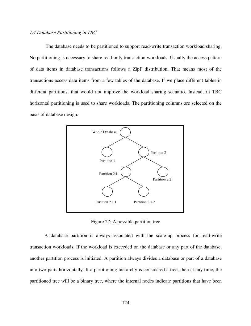
124
7.4 Database Partitioning in TBC
The database needs to be partitioned to support read-write transaction workload sharing.
No partitioning is necessary to share read-only transaction workloads. Usually the access pattern
of data items in database transactions follows a ZipF distribution. That means most of the
transactions access data items from a few tables of the database. If we place different tables in
different partitions, that would not improve the workload sharing scenario. Instead, in TBC
horizontal partitioning is used to share workloads. The partitioning columns are selected on the
basis of database design.
Figure 27: A possible partition tree
A database partition is always associated with the scale-up process for read-write
transaction workloads. If the workload is exceeded on the database or any part of the database,
another partition process is initiated. A partition always divides a database or part of a database
into two parts horizontally. If a partitioning hierarchy is considered a tree, then at any time, the
partitioned tree will be a binary tree, where the internal nodes indicate partitions that have been
Partition 1
Whole Database
Partition 2.1
Partition 2
Partition 2.1.2
Partition 2.2
Partition 2.1.1

125
further partitioned due to excessive workloads and external nodes indicate functional partitions
that are currently serving client requests.
The system architecture of the TBC system has features that are advantageous for auto
scaling, especially for read-only transactions. As any member of the read-set servers can handle a
read-only transaction, deployment of a single server as a read-server can increase the system
capacity significantly. Moreover, push-based communication is established between the root
node and its immediate children who are also members of the read-set of servers. The addition of
a read-server to the system does not increase the overhead to the root node, but it increases the
capacity of the system.
Scale up for an incremental read-write workload needs database partitioning and the
addition of a dedicated write-set of servers to each partition. This scale up process can also speed
up if additional read servers are used as members of the new write-set of servers. Since they
already have updated database servers, no database synchronization is necessary. This is
advantageous, because a database typically has many more read-only transactions than read-
write transactions. The TBC system is very favorable to the auto scaling and partitioning process
required in a cloud system.
7.5 Future Work in Auto Scaling
It is very complex to make decisions about scaling up or scaling down the resources. To
identify when a stable workload exceeds a threshold is very difficult, as the workload can change
for a very short duration of time. For example, the workload may decrease before an additional
resource is ready to be used when scaling up. The same scenario can occur for the scaling-down
process. After scaling-down the resources, the workload may increase again to its original load.
There are some overhead tasks associated with the auto-scaling process in a cloud platform. It is

126
not a good idea to oscillate the scaling-up and scaling-down process with respect to a changing
workload. If it is possible to predict the future workload pattern and make decision of the
scaling-up or scaling-down process in advance, then it will be a great advantage to both cloud
vendors (ensure resource utilization) and clients (better service and SLA assurance).
Future work in TBC will include strategies to determine when to scale up and scale down
in TBC. It is a great challenge for cloud vendors to design an effective auto-scaling and self-
tuning mechanism and ensure pre-determined QoS at minimum cost in changeable workload
handling. There is some existing research to guide our future work in this area. Sanzo et al.[58]
investigate the idea to use machine learning techniques in auto tuning a data grid configuration.
They also try to determine the best configuration to guarantee specific throughput or latency.
With the help of a neural network they proposed efficient ways to predict the workload pattern
and calculate required resources to meet the target throughput or latency. Although these
techniques were designed for a data grid, they may be applicable to a cloud. Ciciani et al. [70]
present the Workload Analyzer (WA) specifically for clouds. They characterize the present and
future workload by aggregating statistical data from various cloud nodes, filtering this data and
correlating the filtered data to build a detailed workload profile of applications deployed on the
cloud platform. The WA also triggers adjustments in possible pre-determined SLAs violations.
Quamar [66] proposes SWORD, a scalable workload-aware data partitioning and placement
approach for OLTP workloads. To reduce the partitioning overhead, he transforms the workload
into a hyper-graph over the data items and compresses that hyper-graph by a proposed
compression technique. He also developed a workload-aware active replication mechanism to
increase availability and balance the load efficiently.

127
A future direction is to design a strategy for the TBC transaction management system to
predict possible changes in workloads. This will allow initiating the auto-scaling process in
advance in order to serve the clients better. This prediction can also be used to identify data
access patterns. Some database partitioning is necessary to support an auto-scaling feature. In a
partitioned database, the performance of the database operation totally depends on the
partitioning. For example, if the most frequently used data items are stored in different partitions,
then it will take a much longer time to process a database operation than if those data items are
stored in the same partition. In the future we will also deploy machine-learning techniques to
find out the data access pattern and partition the database efficiently. A bad partition decision can
counteract the main reason to have a partition. A smart partition decision depends on the
structure and characteristics of the database, user access pattern and much more. The decision of
how the database is partitioned has a significant impact on resource utilization, client
satisfaction, better throughput and response time.

128
CHAPTER 8
CONCLUSION
Data size has been increasing exponentially in the last few years as data production now
reaches in the petabyte level. Data management in the traditional way is becoming obsolete. The
cloud computing paradigm provides a potential platform to develop new applications to manage
such huge data sets. Using cloud applications through portable devices, such as laptops,
netbooks, iPads, PDAs and smart phones, accessing the data will be commonplace in the future
as the idea of a thin client is becoming more popular day by day. Much of the data management
market is transactional data management. Unfortunately, maintaining ACID guarantees makes
transactional data management applications unfavorable for deployment in the cloud. Solutions
have been provided to overcome these obstacles, but consistency remains the bottleneck issue.
Maintaining consistency, availability and high throughput among replica servers is a key
issue in cloud databases. Many highly concurrent systems tolerate data inconsistency across
replicas to support high throughput. However, in many systems, it is still important to maintain
data consistency. Highly unreliable systems can face transaction failures for interdependency
among replica servers, but for some of these systems it remains important to maintain data
consistency despite such failures.
In this dissertation we have proposed a new consistency approach, called TBC, which
reduces the interdependency among replica servers. Experimental results of the execution of
database operations indicate that our TBC approach trades off consistency and availability with

129
performance. We studied the relative performance of the classic approach, the quorum approach
and our tree-based consistency approach for maintaining data consistency. The TBC approach
performed well in terms of response time, despite the heterogeneity of servers, the arrival time,
the read-write ratio or network quality. Overall, the tree-based approach demonstrated better
performance than the existing classic and quorum approaches.
We have also designed and implemented a transaction management system for a cloud
platform using TBC as the consistency approach. This system utilizes a hierarchical lock
manager for the transaction management system to allow more concurrency in database access.
We proved that our transaction management system is able to guarantee the ACID properties and
maintain serializability in highly concurrent access to the database. We also proved that our
system can prevent the common isolation problems such as dirty read, unrepeatable read and
dirty write or lost update.
We conducted experiments to analyze the performance of the proposed transaction
management system compared to the traditional transaction managers of the classic approach and
the quorum approach. Our experiments show that TBC always has better response time and
usually a lower transaction restart percentage than the existing classic approach or quorum
approach. Variations in data selection preference or database size do not affect the performance
of TBC. Experiments demonstrated that TBC also performed better than the existing strategies
for different values for the read-write ratio. Lastly, we included an auto-scaling property to the
transaction management system. The auto-scaling utilizes partitioning to scale up or scale down
as needed to respond to a workload.
The results from this dissertation have shown that it is possible to maintain concurrency
in a cloud database system without sacrificing consistency or response time. Although TBC had

130
good performance for individual read and write operations, its superiority was demonstrated the
most in its performance of database transactions. Results have also shown that the
implementations used in current cloud database systems, such as the quorum approach, may not
always provide the customer with the best performance-based approach for database transaction
processing in cloud platforms. The TBC consistency approach is especially designed for cloud
platforms, so TBC is able to take advantage of the architectural benefits of cloud platforms. Our
research demonstrates that TBC can maintain strong consistency in database transaction
execution, as well as provide customers with better performance than existing approaches.

131
REFERENCES
[1] Brian Hayes. “Cloud Computing.” Communications of the ACM, 9–11, July 2008.
[2] Aaron Weiss. “Computing in the Clouds.” netWorker, 16–25,December 2007.
[3] Luis M. Vaquero, Luis Rodero-Merino, Juan Caceres, and Maik Lindner. “A Break in the
Clouds: Towards a Cloud Definition.” SIGCOMM Comput. Commun. Rev. 39, 50-55,
December 2008.
[4] Jinesh Varia. “Cloud Architectures.” White paper of Amazon Web Service. 2008.
[5] Jason Carolan. “IntroductIon to Cloud Computing Architecture.” White paper of Sun
Microsystem. June 2009.
[6] Judith M. Myerson. “Cloud Computing versus Grid Computing: Service Types, Similarities
and Differences and Things to Consider.” White paper of IBM. 2008.
[7] Daniel J. Abadi. “Data Management in the Cloud: Limitations and Opportunities.” IEEE Data
Eng. Bulletin, 32(1), March 2009.
[8] Matthias Brantner, Daniela Florescuy, David Graf, Donald Kossmann, and Tim Kraska.
“Building a Database on S3.” In Proceedings of the 2008 ACM SIGMOD international
conference on Management of data (SIGMOD '08).
[9] Ronnie Chaiken, Bob Jenkins, Per-Åke Larson, Bill Ramsey, Darren Shakib, Simon Weaver,
and Jingren Zhou. “SCOPE: Easy and Efficient Parallel Processing of Massive Data Sets.”
Proc. VLDB Endow. 1, 2 (August 2008), 1265-1276.
[10] Tim Kraska, Martin Hentschel, Gustavo Alonso, and Donald Kossmann. “Consistency
Rationing in the Cloud: Pay Only When It Matters.” Proc. VLDB Endow. 2, 1 (August
2009), 253-264.
[11] Zhou Wei, Guillaume Pierre, and Chi-Hung Chi. “Scalable Transactions for Web
Applications in the Cloud.” Euro-Par 2009 Parallel Processing. Springer Berlin. V- 5704.
442-453. 2009.
[12] Sudipto Das, Divyakant Agrawal, and Amr El Abbadi. “ElasTraS: An Elastic Transactional
Data Store in the Cloud.” In Proceedings of the 2009 conference on Hot topics in cloud
computing (HotCloud'09). USENIX Association, Berkeley, CA, USA.

132
[13] Werner Vogels. “Eventually Consistent.” Communications of the ACM, 52, 1, 40-44.
January 2009.
[14] Ashraf Aboulnaga, Kenneth Salem, Ahmed A. Soror, Umar Farooq Minhas, Peter
Kokosielis, and Sunil Kamath. “Deploying Database Appliances in the Cloud.” Bulletin of
the Technical Committee on Data Engineering, IEEE Computer Society 32 (1): 13–20, 2009.
[15] Jeffrey Dean, and Sanjay Ghemawat. “MapReduce: Simplified Data Processing on Large
Clusters.” In OSDI’04: Proceedings of the 6th conference on Symposium on Opearting
Systems Design & Implementation (Berkeley, CA, USA, 2004), USENIX Association, pp.
10–10.
[16] Eric Brewer. “Towards Robust Distributed Systems.” Annual ACM Symposium on
Principles of Distributed Computing. Page 7, July 2000.
[17] Rakesh Agrawal, Anastasia Ailamaki, Philip A. Bernstein, Eric A. Brewer, Michael J.
Carey, Surajit Chaudhuri, Anhai Doan, Daniela Florescu, Michael J. Franklin, Hector Garcia-
Molina, Johannes Gehrke, Le Gruenwald, Laura M. Haas, Alon Y. Halevy, Joseph M.
Hellerstein, Yannis E. Ioannidis, Hank F. Korth, Donald Kossmann, Samuel Madden, Roger
Magoulas, Beng Chin Ooi, Tim O'Reilly, Raghu Ramakrishnan, Sunita Sarawagi, Michael
Stonebraker, Alexander S. Szalay, and Gerhard Weikum. “The Claremont Report on
Database Research.” Commun. ACM 52, 6, 56-65. June 2009.
[18] B. G. Lindsay, P. G. Selinger, C. Galtieri, J. N. Gray, R. A. Lorie, T. G. Price, F. Putzolu,
and B. W. Wade. “Notes on Distributed Databases.” Report No. RJ2571, IBM San Jose
Research Laboratory, July 1979.
[19] Md. Ashfakul Islam, and Susan V. Vrbsky, “A Tree-Based Consistency Approach for Cloud
Databases.” 2010 IEEE Second International Conference on Cloud Computing Technology
and Science (CloudCom) 401-404, Nov. 30 2010-Dec. 3 2010.
[20] Edward Walker, Walter Brisken, and Jonathan Romney. “To Lease or not To Lease from
Storage Clouds.” IEEE Computer. vol.43, no.4, pp.44-50. April 2010.
[21] Bruno Ciciani, Diego Didona, Pierangelo Di Sanzo, Roberto Palmieri, Sebastiano Peluso,
Francesco Quaglia, and Paolo Romano, “Automated Workload Characterization in Cloud-
based Transactional Data Grids.” Parallel and Distributed Processing Symposium Workshops
& PhD Forum (IPDPSW), 2012 IEEE 26th International , vol., no., pp.1525,1533, 21-25
May 2012.
[22] Simon Wardley, Etienne Goyer, and Nick Barcet. “Ubuntu Enterprise Cloud Architecture.”
Technical report, Canonical, August 2009.
[23] Daniel Nurmi, Rich Wolski,Chris Grzegorczyk, Graziano Obertelli, Sunil Soman, Lamia
Youseff, and Dmitrii Zagorodnov. “The Eucalyptus Open-source Cloud-computing System.”
9th IEEE/ACM International Symposium on Cluster Computing and the Grid, CCGRID.
pp.124-131, 18-21 May 2009 .

133
[24] David Chappell. “A Short Introduction to Cloud Platforms.” David Chappell & Associates,
http://www.davidchappell.com/CloudPlatforms–Chappell.pdf. August 2008.
[25] Tony Bain. “Is the Relational Database Doomed?” ReadWriteWeb.com, 2008. [Online].
Available: http://www.readwriteweb.com/archives/is the relational database doomed.php
[26] Carlo Curino, Evan Jones, Yang Zhang, Eugene Wu, and Sam Madden. “Relational Cloud:
The Case for a Database Service.” Technical Report 2010-14, CSAIL, MIT, 2010.
[27] Philip H. Carns, Bradley W. Settlemyer, and Walter B. Ligon. “Using Server to Server
Communication in Parallel File Systems to Simplify Consistency and Improve Performance.”
in Proc. the 2008 ACM/IEEE Conference on Super-computing (SC’08), Austin, TX, 2008.
[28] Hakan. Hacigumus, Bala. Iyer, Chen Li, and Sharad. Mehrotra. “Executing SQL Over
Encrypted Data in the Database-Service-Provider Model.” In Proc. of SIGMOD, pages 216–
227, 2002.
[29] David B. Lomet, Alan Fekete, Gerhard Weikum, and Mike. J. Zwilling. “Unbundling
Transaction Services in the Cloud.” In CIDR, Jan. 2009.
[30] Doug Beaver, Sanjeev Kumar, Harry C. Li, Jason Sobel, and Peter Vajgel. “Finding a
Needle in Haystack: Facebook’s Photo Storage.” In Proceedings of the 9th USENIX
Symposium on Operating Systems Design and Implementation (OSDI ’10), Vancouver,
Canada, October 2010.
[31] Fay Chang, Jeffrey Dean, Sanjay Ghemawat, Wilson C. Hsieh, Deborah A. Wallach, Mike
Burrows, Tushar Chandra, Andrew Fikes, and Robert E.Gruber. “Bigtable: A Distributed
Storage System for Structured Data.” In Proceedings of the 7thConference on USENIX
Symposium on Operating Systems Design and Implementation - Volume 7, pages 205–218,
2006.
[32] Ryan Jansen, and Paul R. Brenner. “Energy Efficient Virtual Machine Allocation in the
Cloud.” 2011 International Green Computing Conference and Workshops (IGCC),vol., no.,
pp.1-8, 25-28 July 2011.
[33] Daniel Ford, Francois Labelle, Florentina I. Popovici, Murray Stokely, Van-Anh Truong,
Luiz Barroso, Carrie Grimes, and Sean Quinlan. “Availability in Globally Distributed
Storage Systems.” In USENIX OSDI, pages 1–7, 2010.
[34] Roxana Geambasu, Amit A. Levy, and Tadayoshi Kohno. “Comet: An Active Distributed
Key-Value Store.” In OSDI, 2010.
[35] Haryadi S. Gunawi, Thanh Do, Pallavi Joshi, Peter Alvaro, and Joseph M. Hellerstein.
“FATE and DESTINI: A Framework for Cloud Recovery Testing.” In NSDI (to appear),
2011.
[36] Alexander Keremidarski. “MySQL Replication”, 2003. WWW: http://dev.mysql.com/tech-
resources/presentations/ (last checked 09/24/2005).

134
[37] Sanjay Ghemawat, Howard Gobioff, and Shun-Tak Leung. “The Google file system.”
SIGOPS Oper. Syst. Rev. 37, 5 (October 2003), 29-43.
[38] “Xeround The Cloud Database.” Xeround White paper. January 2012.
http://xeround.com/main/wp-content/uploads/2012/03/Xeround-cloud-database-
whitepaper.pdf
[39] Md. Ashfakul Islam. “Performance Comparison of Consistency Maintenance Techniques
for Cloud Database.” In Proceedings of the 50th Annual Southeast Regional
Conference (ACM-SE '12).
[40] Md Ashfakul Islam, Susan V. Vrbsky, and Mohammad A. Hoque. “Performance Analysis
of a Tree-Based Consistency Approach for Cloud Databases.” Computing, Networking and
Communications (ICNC), 2012 International Conference on , pp.39-44, Jan. 30 2012-Feb. 2
2012.
[41] Yoav Raz. “The Principle of Commitment Ordering, or Guaranteeing Serializability in a
Heterogeneous Environment of Multiple Autonomous Resource Mangers Using Atomic
Commitment.” In Proceedings of the 18th International Conference on Very Large Data
Bases 1992.
[42] Laura C. Voicu, Heiko Schuldt, Fuat Akal, Yuri Breitbart, and Hans J. Schek. “Re:GRIDiT
– Coordinating Distributed Update Transactions on Replicated Data in the Grid.” 10th
IEEE/ACM International Conference on Grid Computing (Grid 2009), Banff, Canada.
[43] Giuseppe DeCandia, Deniz Hastorun, Madan Jampani, Gunavardhan Kakulapati, Avinash
Lakshman, Alex Pilchin, Swaminathan Sivasubramanian, Peter Vosshall, and Werner
Vogels. “Dynamo: Amazon’s Highly Available Key-Value Store.” In Proceedings of twenty-
first ACM SIGOPS symposium on Operating systems principles (2007),pp. 205–220.
[44] Technical Document. Azure Microsoft Cloud. http://www.windowsazure.com/en-
us/develop/overview/
[45] Technical Report. Amazon RDS. http://aws.amazon.com/rds/amazon-rds-
introduced/amazon-rds-whitepaper/
[46] Eric Brewer. “CAP Twelve Years Later: How the Rules Have Changed.” IEEE Computer,
vol 45, no 2, page 23-29, February 2012.
[47] Simon S.Y. Shim, “The CAP Theorem’s Growing Impact.” IEEE Computer, vol 45, no 2,
page 21 -22, February 2012.
[48] Seth Gilbert, Nancy A. Lynch. “Perspectives on the CAP Theorem.” IEEE Computer, vol
45, no 2, page 30-35. February 2012.
[49] Daniel J. Abadi. “Consistency Tradeoffs in Modern Distributed Database System Design.”
IEEE Computer, vol 45, no 2, page 37-42. February 2012.

135
[50] Kenneth P. Birman, Daniel A Freedman, Qi Huang and Patrick Dowell. “Overcoming CAP
with Consistent Soft-State Replication.” IEEE Computer, vol 45, no 2, Page 50-57. February
2012.
[51] Donald Kossmann, Tim Kraska, and Simon Loesing. “An Evaluation of Alternative
Architectures for Transaction Processing in the Cloud.” In Proceedings of the 2010 ACM
SIGMOD International Conference on Management of data (SIGMOD '10). ACM, New
York, NY, USA, 579-590. 2010.
[52] Abraham Silberschatz, Henry Korth, and S. Sudarshan. “Database Systems Concepts (5
ed.).” Chapter 15. McGraw-Hill, Inc., New York, NY, USA. 2010.
[53] Ramez Elmasri and Shamkant Navathe. “Fundamentals of Database Systems (6th ed.).”
Chapter 21. Addison-Wesley Publishing Company,USA.
[54] Lehner, Wolfgang, and Kai-Uwe Sattler. “Transactional Data Management Services for the
Cloud.” Web-Scale Data Management for the Cloud. Springer 59-90, New York. USA. 2013.
[55] Philip A. Bernstein, Vassco Hadzilacos, and Nathan Goodman. “Concurrency Control and
Recovery in Database Systems.” Addison-Wesley Longman Publishing Co., Inc., Boston,
MA, USA.
[56] Wentian Li . “Random Texts Exhibit Zipf's-Law-Like Word Frequency Distribution.” IEEE
Transactions on Information Theory 38 (6): 1842–1845. 1992.
[57] Kris Jamsa. “Cloud Computing (1st Ed.). ” Jones and Bartlett Publishers, Inc., USA. 2012.
[58] Pierangelo Di Sanzo, Diego Rughetti, Bruno Ciciani, and Francesco Quaglia. “Auto-Tuning
of Cloud-Based In-Memory Transactional Data Grids via Machine Learning.” In Proceedings
of the 2012 Second Symposium on Network Cloud Computing and Applications (NCCA
'12). IEEE Computer Society, Washington, DC, USA, 9-16.
[59] Changbin Liu, Yun Mao, Xu Chen, Mary F. Fernández, Boon Thau Loo, and Jacobus E.
Van Der Merwe. “TROPIC: Transactional Resource Orchestration Platform In the Cloud.”
In Proceedings of the 2012 USENIX conference on Annual Technical Conference (USENIX
ATC'12). USENIX Association, Berkeley, CA, USA, 16-16.
[60] Avrilia Floratou, Jignesh M. Patel, Willis Lang, and Alan Halverson. “When Free is not
Really Free: What Does It Cost to Run a Database Workload in the Cloud?” In Proceedings
of the Third TPC Technology conference on Topics in Performance Evaluation,
Measurement and Characterization (TPCTC'11), Berlin, Heidelberg, 163-179.
[61] Sanjeev Kumar Pippal, and Dharmender Singh Kushwaha. “A Simple, Adaptable and
Efficient Heterogeneous Multi-Tenant Database Architecture for Ad Hoc Cloud.” Journal of
Cloud Computing: Advances, Systems and Applications 2013. Vol 2 no 5.

136
[62] Yvette E. Gelogo and Sunguk Lee. “Database Management System as a Cloud Service.”
International Journal of Future Generation Communication and Networking, Vol. 5, No. 2,
Page 71-76, June, 2012.
[63] Chengliang Sang , Qingzhong Li, Zhengzheng Liu , and Lanju Kong. “VGL: Variable
Granularity Lock Mechanism in the Shared Storage Multi-tenant Database.” ECICE 2012,
AISC 146, pp. 481–487
[64] Ricardo Padilha, and Fernando Pedone. “Augustus: Scalable and Robust Storage for Cloud
Applications.” In Proceedings of the 8th ACM European Conference on Computer
Systems(EuroSys '13). ACM, New York, NY, USA, 99-112.
[65] Hoang Tam Vo, Sheng Wang, Divyakant Agrawal, Gang Chen, and Beng Chin Ooi.
“LogBase: A Scalable Log-Structured Database System in the Cloud.” Proc. VLDB
Endow. 5, 10 (June 2012), 1004-1015.
[66] Abdul Quamar, K. Ashwin Kumar, and Amol Deshpande. “SWORD: scalable workload-
aware data placement for transactional workloads.” In Proceedings of the 16th International
Conference on Extending Database Technology (EDBT '13). ACM, New York, NY, USA,
430-441.
[67] Barzan Mozafari, Carlo Curino, and Samuel Madden. “DBSeer: Resource and Performance
Prediction for Building a Next Generation Database Cloud.” 6th Biennial Conference on
Innovative Data Systems Research (CIDR '13) , Asilomar, California, USA.January 6-9,
2013.
[68] Hiroshi Wada, Alan Fekete , Liang Zhao, Kevin Lee, and Anna Liu. “Data Consistency
Properties and the Trade-offs in Commercial Cloud Storages: the Consumers’ Perspective .”
CIDR’11 Asilomar, California, January 2011.
[69] Justin J. Levandoski, David Lomet, Mohamed F. Mokbel, and Kevin Keliang.
“Deuteronomy: Transaction Support for Cloud Data.” CIDR'11, Asilomar, California, USA,
January 9-12, 2011.
[70] Bruno Ciciani, Diego Didona, Pierangelo Di Sanzo, Roberto Palmieri, Sebastiano Peluso,
Francesco Quaglia, and Paolo Romano. “Automated Workload Characterization in Cloud-
based Transactional Data Grids.” In Proceedings of the 2012 IEEE 26th International Parallel
and Distributed Processing Symposium Workshops & PhD Forum (IPDPSW '12). IEEE
Computer Society, Washington, DC, USA, 1525-1533.
[71] Divyakant Agrawal, Amr El Abbadi, Beng Chin Ooi, Sudipto Das, and Aaron J. Elmore.
“The Evolving Landscape of Data Management in the Cloud.” Int. J. Comput. Sci. Eng. 7, 1
(March 2012), 2-16.
[72] Diego Didona, Paolo Romano, Sebastiano Peluso, and Francesco Quaglia. “Transactional
Auto Scaler: Elastic Scaling of In-Memory Transactional Data Grids.” In Proceedings of the
9th international conference on Autonomic computing (ICAC '12). ACM, New York, NY,
USA, 125-134.

137
[73] Markus Klems, David Bermbach, and Rene Weinert. “A Runtime Quality Measurement
Framework for Cloud Database Service Systems.” In Proceedings of the 2012 Eighth
International Conference on the Quality of Information and Communications
Technology(QUATIC '12). IEEE Computer Society, Washington, DC, USA, 38-46.
[74] James C. Corbett, Jeffrey Dean, Michael Epstein, Andrew Fikes, Christopher Frost, J. J.
Furman, Sanjay Ghemawat, Andrey Gubarev, Christopher Heiser, Peter Hochschild, Wilson
Hsieh, Sebastian Kanthak, Eugene Kogan, Hongyi Li, Alexander Lloyd, Sergey Melnik,
David Mwaura, David Nagle, Sean Quinlan, Rajesh Rao, Lindsay Rolig, Yasushi Saito,
Michal Szymaniak, Christopher Taylor, Ruth Wang, and Dale Woodford . “Spanner:
Google’s globally-distributed database.” To appear in Proceedings of OSDI (2012).
[75] Sudipto Das, Divyakant Agrawal, and Amr El Abbadi. “G-Store: A Scalable Data Store for
Transactional Multi Key Access in the Cloud." In Proceedings of the 1st ACM symposium
on Cloud computing, pp. 163-174. ACM, 2010.
[76] Ken Birman, Gregory Chockler, and Robbert van Renesse. “Toward a Cloud Computing
Research Agenda.” ACM SIGACT News 40, no. 2 (2009): 68-80.
[77] Divyakant Agrawal, Sudipto Das, and Amr El Abbadi. “Big Data and Cloud Computing:
Current State and Future Opportunities.” In Proceedings of the 14th International Conference
on Extending Database Technology, pp. 530-533. ACM, 2011.
[78] Hoang Tam Vo, Chun Chen, and Beng Chin Ooi. “Towards Elastic Transactional Cloud
Storage With Range Query Support.” Proceedings of the VLDB Endowment3, no. 1-2
(2010): 506-514.
[79] Divyakant Agrawal, Sudipto Das, and Amr El Abbadi. “Big data and cloud computing: new
wine or just new bottles?” Proceedings of the VLDB Endowment 3, no. 1-2 (2010): 1647-
1648.
[80] Aaron J. Elmore, Sudipto Das, Divyakant Agrawal, and Amr El Abbadi. “Zephyr: Live
Migration in Shared Nothing Databases for Elastic Cloud Platforms.” In SIGMOD
Conference, pp. 301-312. 2011.
[81] Paolo Romano, Luis Rodrigues, Nuno Carvalho, and Joäo Cachopo. “Cloud-TM:
Harnessing the Cloud With Distributed Transactional Memories.” ACM SIGOPS Operating
Systems Review 44, no. 2 (2010): 1-6.
[82] Navraj Chohan, Chris Bunch, Chandra Krintz, and Yoshihide Nomura. “Database-Agnostic
Transaction Support for Cloud Infrastructures.” In Cloud Computing (CLOUD), 2011 IEEE
International Conference on, pp. 692-699. IEEE, 2011.
[83] Brandon Rich, and Douglas Thain. “DataLab: Transactional Data-Parallel Computing on an
Active Storage Cloud.” In Proceedings of the 17th international symposium on High
performance distributed computing, pp. 233-234. ACM, 2008.

138
[84] Chun Chen, Gang Chen, Dawei Jiang, Beng Chin Ooi, Hoang Tam Vo, Sai Wu, and
Quanqing Xu. “Providing Scalable Database Services on the Cloud.” In Web Information
Systems Engineering–WISE 2010, pp. 1-19. Springer Berlin Heidelberg, 2010.
[85] Emmanuel Cecchet, Rahul Singh, Upendra Sharma, and Prashant Shenoy. “Dolly:
Virtualization-Driven Database Provisioning for the Cloud.” In ACM SIGPLAN Notices,
vol. 46, no. 7, pp. 51-62. ACM, 2011.
[86] Peter Membrey, Eelco Plugge, and Tim Hawkins. “The Definitive Guide to MongoDB: the
noSQL Database for Cloud and Desktop Computing.” Apress, 2010.
[87] Thomas Gazagnaire, and Vincent Hanquez. “Oxenstored: An Efficient Hierarchical and
Transactional Database Using Functional Programming With Reference Cell Comparisons.”
In ACM Sigplan Notices, vol. 44, no. 9, pp. 203-214. ACM, 2009.
[88] Bhaskar Prasad Rimal, Admela Jukan, Dimitrios Katsaros, and Yves Goeleven.
“Architectural Requirements For Cloud Computing Systems: An Enterprise Cloud
Approach.” Journal of Grid Computing 9, no. 1 (2011): 3-26.
[89] Francisco Maia, José Enrique Armendáriz-Inigo, M. Idoia Ruiz-Fuertes, and Rui Oliveira.
“Scalable Transactions in the Cloud: Partitioning Revisited.” In On the Move to Meaningful
Internet Systems, OTM 2010, pp. 785-797. Springer Berlin Heidelberg, 2010.
[90] Jing Han, Meina Song, and Junde Song. “A Novel Solution of Distributed Memory NoSQL
Database for Cloud Computing.” In Computer and Information Science (ICIS), 2011
IEEE/ACIS 10th International Conference on, pp. 351-355. IEEE, 2011.
[91] Scott Klein, and Herve Roggero. “Getting Started with SQL Database.” In Pro SQL
Database for Windows Azure, pp. 1-22. Apress, 2012.
[92] Christine G Martinez. “Study of Resource Management for Multitenant Database Systems
in Cloud Computing.” PhD diss., University of Colorado, 2012.
[93] Siba Mohammad, Sebastian Breß, and Eike Schallehn. “Cloud Data Management: A Short
Overview and Comparison of Current Approaches.” In24th GI-Workshop on Foundations of
Databases (Grundlagen von Datenbanken). 2012.
[94] Kyuseok Shim, Sang Kyun Cha, Lei Chen, Wook-Shin Han, Divesh Srivastava, Katsumi
Tanaka, Hwanjo Yu, and Xiaofang Zhou. “Data Management Challenges and Opportunities
in Cloud Computing.” In Database Systems for Advanced Applications, pp. 323-323.
Springer Berlin Heidelberg, 2012.
[95] Ursula Torres-Parejo, Jesús R. Campaña, Miguel Delgado, and M. Amparo Vila. “MTCIR:
A Multi-Term Tag Cloud Information Retrieval System.” Expert Systems with
Applications (2013).
[96] Umar Farooq Minhas. “Scalable and Highly Available Database Systems in the Cloud.”
PhD diss., University of Waterloo, 2013.

139
[97] Tim Kraska, and Beth Trushkowsky. “The New Database Architectures.” Internet
Computing, IEEE 17, no. 3 (2013): 72-75.

140
APPENDIX
In this appendix, we are going to discuss about the implementation details of the
simulation program that is used for experiments and performance analysis. The simulation
program is written in JAVA programming language. Codes of the required classes are given
bellow:
Relation Class: This class represents the Table object of a database.
1 class Relation implements Serializable{
2 private static final long serialVersionUID = 1L;
3 public int id;
4 public int vrsn;
5 public int no_req_col;
6 public int cols[];
7
8 public Relation(int cols){
9 cols = new int[cols];
10 vrsn = -1;
11
12 for(int i = 0; i < cols; i++)
13 cols[i] = 0;
14 }
15 }
Operation Class: This class represents the characteristics of a typical database operation.
1 class Operation implements Serializable{
2 private static final long serialVersionUID = 1L;
3 public int id;

141
4 public char type;
5 public int no_req_rel;
6 public ArrayList<Relation> relations;
7
8 public Operation(){
9 relations = new ArrayList<Relation>();
10 }
11 }
Transaction Class: This class represents a typical database transaction.
1 class Transaction implements Serializable {
2 private static final long serialVersionUID = 1L;
3 public int id;
4 public int restarted;
5 public char type;
6 public int no_op;
7 public ArrayList<Operation> operations;
8
9 public Transaction (){
10 operations = new ArrayList<Operation>();
11 }
12 }
TransactionGenerator Class: This class generates transactions and sends to appropriate
nodes based on the mode parameter. Mode parameter selects consistency approach between
classic, quorum and TBC.
1 class TransactionGenerator implements Runnable {
2 public static int flipflop = 0;
3 public int id;
4 public int no_op;
5 public boolean cont;
6 public char mode;
7
8 public static int Col = 15;
9 public static int Row = 25;
10 public static Zipf relation = new Zipf(Row, 1.01);

142
11 public static Zipf column = new Zipf(Col, 1.01);
12 public static Random tran_rd_or_wr = new Random(932498310);
13 public static Random op_rd_or_wr = new Random(830932812);
14 public static Random no_operation = new Random(748320980);
15 public static Random req_relation = new Random(782300112);
16 public static Random req_column = new Random(300897101);
17 public static double readwriteratio = .8;
18
19 public Transaction T;
20 public long start;
21 public long end;
22 public double rdelay;
23
24 public TransactionGenerator (int id, char mode){
25 this.mode = mode;
26 this.id = id;
27 start = end = 0;
28 T = new Transaction();
29 T.id = id;
30 T.restarted = 0;
31 T.no_op = (int) (2 + (no_operation.nextDouble() * 100 ) % 5);
32
33 if(tran_rd_or_wr.nextDouble() < readwriteratio)
34 T.type = 'R';
35 else
36 T.type = 'W';
37
38 for(int i =0; i < T.no_op; i++) {
39 Operation O = new Operation();
40 O.id = i;
41 O.no_req_rel = (int) (1 + (req_relation.nextDouble() * 100 ) % 4);
42
43 if(T.type == 'W')
44 if(op_rd_or_wr.nextDouble() < 0.7)
45 O.type = 'W';
46 else
47 O.type = 'R';
48 else
49 O.type = 'R';
50
51 for(int j = 0; j < O.no_req_rel; j++){
52 Relation R = new Relation();
53 R.id = relation.nextInt();
54 R.no_req_col = (int) (1 + (req_column.nextDouble() * 100 ) % 5);
55
56 for(int k = 0; k < R.no_req_col; k++){

143
57 int colId = column.nextInt();
58 R.cols[colId] = 1;
59
60 if(O.type == 'W' && CCTransactionHandler.version[R.id][colId] < T.id)
61 CCTransactionHandler.version[R.id][colId] = T.id;
62 else if(T.type == 'R' && R.vrsn < CCTransactionHandler.version[R.id][colId] )
63 R.vrsn = CCTransactionHandler.version[R.id][colId];
64 }
65 O.relations.add(R);
66 }
67 T.operations.add(O);
68 }
69 Thread t = new Thread(this);
70 t.start();
71 }
72
73 public void run(){
74 TransactionHandler.MessageFlag[id] = false;
75 int mode;
76 if (this.mode == 'C' || this.mode == 'c')
77 mode = 5;
78 else if(this.mode == 'Q' || this.mode == 'q')
79 mode = 5;
80 else
81 mode = 2;
82
83 if(T.type == 'R'){
84 if((flipflop % mode) == 0)
85 TransactionHandler.MessageTrack[id] = new SendMessage( new byte[]
{(byte)192,(byte)168,(byte)0,(byte)101}, T, 0.995);
86 else if((flipflop % mode) == 1)
87 TransactionHandler.MessageTrack[id] = new SendMessage( new byte[]
{(byte)192,(byte)168,(byte)0,(byte)102}, T, 0.995);
88 else if((flipflop % mode) == 2)
89 TransactionHandler.MessageTrack[id] = new SendMessage( new byte[]
{(byte)192,(byte)168,(byte)0,(byte)103}, T, 0.995);
90 else if((flipflop % mode) == 3)
91 TransactionHandler.MessageTrack[id] = new SendMessage( new byte[]
{(byte)192,(byte)168,(byte)0,(byte)104}, T, 0.995);
92 else if((flipflop % mode) == 4)
93 TransactionHandler.MessageTrack[id] = new SendMessage( new byte[]
{(byte)192,(byte)168,(byte)0,(byte)105}, T, 0.995);
94 flipflop++;
95 }
96 else {
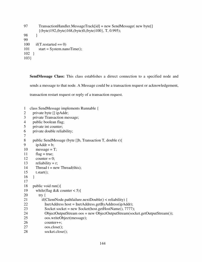
144
97 TransactionHandler.MessageTrack[id] = new SendMessage( new byte[]
{(byte)192,(byte)168,(byte)0,(byte)100}, T, 0.995);
98 }
99
100 if(T.restarted == 0)
101 start = System.nanoTime();
102 }
103}
SendMessage Class: This class establishes a dirrect connection to a specified node and
sends a message to that node. A Message could be a transaction request or acknowledgement,
transaction restart request or reply of a transaction request.
1 class SendMessage implements Runnable {
2 private byte [] ipAddr;
3 private Transaction message;
4 public boolean flag;
5 private int counter;
6 private double reliability;
7
8 public SendMessage (byte []b, Transaction T, double r){
9 ipAddr = b;
10 message = T;
11 flag = true;
12 counter = 0;
13 reliability = r;
14 Thread t = new Thread(this);
15 t.start();
16 }
17
18 public void run(){
19 while(flag && counter < 5){
20 try {
21 if(ClientNode.pathfailure.nextDouble() < reliability) {
22 InetAddress host = InetAddress.getByAddress(ipAddr);
23 Socket socket = new Socket(host.getHostName(), 7777);
24 ObjectOutputStream oos = new ObjectOutputStream(socket.getOutputStream());
25 oos.writeObject(message);
26 counter++;
27 oos.close();
28 socket.close();

145
29
30 if(message.type == 'A')
31 flag = false;
32 }
33
34 try {
35 Thread.sleep((long)( 400 ));
36 } catch (InterruptedException ie) {
37 System.out.println(ie.getMessage());
38 }
39 } catch (UnknownHostException e) {
40 e.printStackTrace();
41 } catch (IOException e) {
42 e.printStackTrace();
43 }
44 }
45 }
46 }
ClientNode Class: This class performs the tasks of a user node.
1 public class ClientNode {
2 private ServerSocket server;
3 private int port = 7777;
4 private char mode;
5 public static Random transaction_arrival = new Random(1234567890);
6 public static Random pathfailure = new Random(1231231231);
7 public static Random pathdelay = new Random(987987987);
8 public static Random restartdelay = new Random(654654654);
9
10 public ClientNode(char mode) {
11 this.mode = mode;
12 try {
13 server = new ServerSocket(port);
14 } catch (IOException e) {
15 e.printStackTrace();
16 }
17 }
18
19 public static void main(String[] args) {
20 char mode = args[0].charAt[0];
21 ClientNode client = new ClientNode(mode);
22 new TransactionHandler(mode);

146
23 client.handleConnection();
24 }
25
26 public void handleConnection() {
27 System.out.println("Waiting for server update reply");
28
29 while (true) {
30 try {
31 Socket socket = server.accept();
32 new ConnectionHandler(socket);
33 } catch (IOException e) {
34 e.printStackTrace();
35 }
36 }
37 }
38 }
ConnectionHandler Class: This class manages the network connections at the user end.
1 class ConnectionHandler implements Runnable {
2 private Socket socket;
3 private char mode;
4
5 public ConnectionHandler(Socket socket) {
6 this.socket = socket;
7 Thread t = new Thread(this);
8 t.start();
9 }
10
11 public void run() {
12 try {
13 ObjectInputStream ois = new ObjectInputStream(socket.getInputStream());
14 Transaction message = (Transaction) ois.readObject();
15 InetAddress sender = socket.getInetAddress();
16 ois.close();
17 socket.close();
18
19 InetAddress UB0 = InetAddress.getByAddress(new byte[]
{(byte)192,(byte)168,(byte)0,(byte)100});
20 InetAddress UB1 = InetAddress.getByAddress(new byte[]
{(byte)192,(byte)168,(byte)0,(byte)101});
21 InetAddress UB2 = InetAddress.getByAddress(new byte[]
{(byte)192,(byte)168,(byte)0,(byte)102});
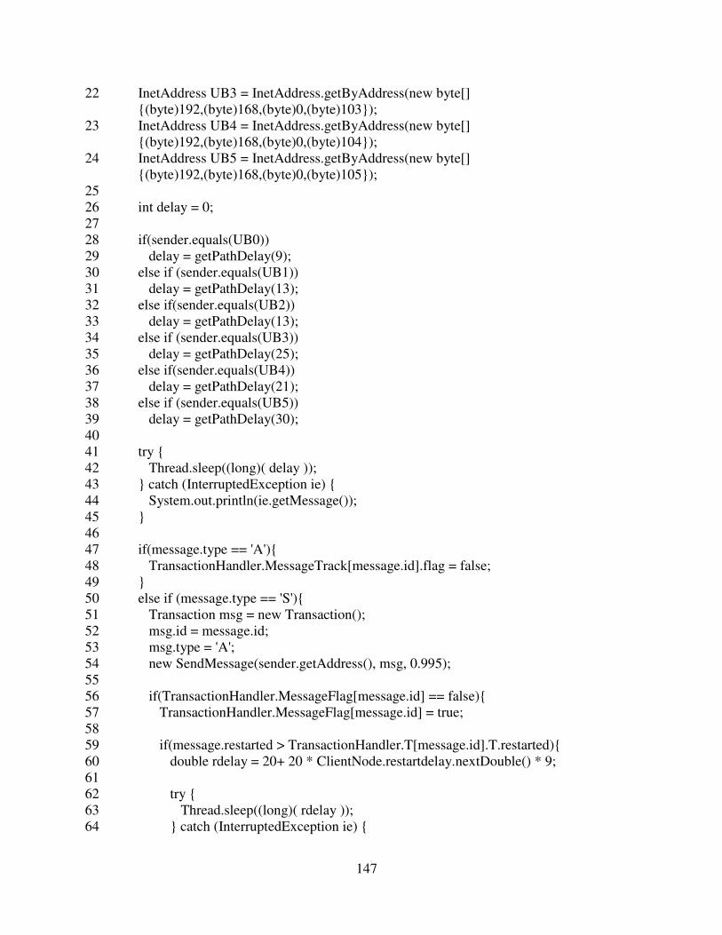
147
22 InetAddress UB3 = InetAddress.getByAddress(new byte[]
{(byte)192,(byte)168,(byte)0,(byte)103});
23 InetAddress UB4 = InetAddress.getByAddress(new byte[]
{(byte)192,(byte)168,(byte)0,(byte)104});
24 InetAddress UB5 = InetAddress.getByAddress(new byte[]
{(byte)192,(byte)168,(byte)0,(byte)105});
25
26 int delay = 0;
27
28 if(sender.equals(UB0))
29 delay = getPathDelay(9);
30 else if (sender.equals(UB1))
31 delay = getPathDelay(13);
32 else if(sender.equals(UB2))
33 delay = getPathDelay(13);
34 else if (sender.equals(UB3))
35 delay = getPathDelay(25);
36 else if(sender.equals(UB4))
37 delay = getPathDelay(21);
38 else if (sender.equals(UB5))
39 delay = getPathDelay(30);
40
41 try {
42 Thread.sleep((long)( delay ));
43 } catch (InterruptedException ie) {
44 System.out.println(ie.getMessage());
45 }
46
47 if(message.type == 'A'){
48 TransactionHandler.MessageTrack[message.id].flag = false;
49 }
50 else if (message.type == 'S'){
51 Transaction msg = new Transaction();
52 msg.id = message.id;
53 msg.type = 'A';
54 new SendMessage(sender.getAddress(), msg, 0.995);
55
56 if(TransactionHandler.MessageFlag[message.id] == false){
57 TransactionHandler.MessageFlag[message.id] = true;
58
59 if(message.restarted > TransactionHandler.T[message.id].T.restarted){
60 double rdelay = 20+ 20 * ClientNode.restartdelay.nextDouble() * 9;
61
62 try {
63 Thread.sleep((long)( rdelay ));
64 } catch (InterruptedException ie) {

148
65 System.out.println(ie.getMessage());
66 }
67
68 TransactionHandler.counter++;
69 TransactionHandler.T[message.id].T.restarted++;
70 TransactionHandler.T[message.id].run();
71 }
72 }
73 }else {
74 if(TransactionHandler.MessageFlag[message.id] == false){
75 TransactionHandler.T[message.id].end = System.nanoTime();
76 System.out.println("Transaction" + message.type + message.id + " is received from
" + sender.toString() );
77 TransactionHandler.MessageFlag[message.id] = true;
78 }
79
80 Transaction msg = new Transaction();
81 msg.id = message.id;
82 msg.type = 'A';
83 new SendMessage(sender.getAddress(), msg, 0.995);
84 }
85 } catch (IOException e) {
86 e.printStackTrace();
87 } catch (ClassNotFoundException e) {
88 e.printStackTrace();
89 }
90 }
91
92 int getPathDelay(int seed){
93 double rand = ClassicClientNode.pathdelay.nextDouble();
94 int delay = 0;
95
96 if(rand < .4)
97 delay = seed;
98 else if (rand <.8)
99 delay = seed + 1;
100 else if(rand < .9)
101 delay = (int) (seed + seed * .2);
102 else if(rand < .95)
103 delay = (int) (seed + 40 * .4);
104 else if(rand < .99)
105 delay = (int) (seed + 40 * .8);
106 else
107 delay = seed + 50 ;
108
109 return delay;

149
110 }
111}
TransactionHandler Class: This class handles transaction requests at the user end.
1 class TransactionHandler implements Runnable {
2 public char mode;
3 public static final int notr = 2000;
4 public static int counter = 0;
5 public static int [][]version = new int [TransactionGenerator.Row][
TransactionGenerator.Col];
6 public static TransactionGenerator [] T = new TransactionGenerator [notr];
7 public static boolean []MessageFlag = new boolean[notr];
8 public static boolean []TranFlag = new boolean[notr];
9 public static SendMessage []MessageTrack = new SendMessage[notr];
10 public static double arrivalRate = .15;
11
12 public TransactionHandler(char mode) {
13 this.mode = mode;
14
15 for(int i = 0; i < notr; i++)
16 MessageFlag[i] = false;
17 for(int i = 0; i < CCTransactionManager.Row; i++)
18 for(int j = 0; j < CCTransactionManager.Col; j++)
19 version[i][j] = -1;
20 Thread t = new Thread(this);
21 t.start();
22 }
23
24 public static int getPoisson(double lambda) {
25 double L = Math.exp(-lambda);
26 double p = 1.0;
27 int k = 0;
28
29 do {
30 k++;
31 p *= ClientNode.transaction_arrival.nextDouble();
32 } while (p > L);
33
34 return k - 1;
35 }
36
37
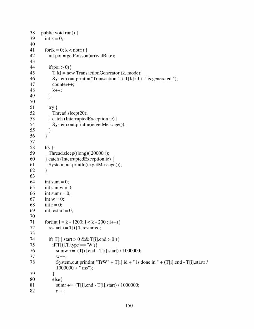
150
38 public void run() {
39 int k = 0;
40
41 for(k = 0; k < notr;) {
42 int poi = getPoisson(arrivalRate);
43
44 if(poi > 0){
45 T[k] = new TransactionGenerator (k, mode);
46 System.out.println("Transaction " + T[k].id + " is generated ");
47 counter++;
48 k++;
49 }
50
51 try {
52 Thread.sleep(20);
53 } catch (InterruptedException ie) {
54 System.out.println(ie.getMessage());
55 }
56 }
57
58 try {
59 Thread.sleep((long)( 20000 ));
60 } catch (InterruptedException ie) {
61 System.out.println(ie.getMessage());
62 }
63
64 int sum = 0;
65 int sumw = 0;
66 int sumr = 0;
67 int w = 0;
68 int r = 0;
69 int restart = 0;
70
71 for(int i = k - 1200; i < k - 200 ; i++){
72 restart += T[i].T.restarted;
73
74 if( T[i].start > 0 && T[i].end > 0 ){
75 if(T[i].T.type == 'W'){
76 sumw += (T[i].end - T[i].start) / 1000000;
77 w++;
78 System.out.println( "TrW" + T[i].id + " is done in " + (T[i].end - T[i].start) /
1000000 + " ms");
79 }
80 else{
81 sumr += (T[i].end - T[i].start) / 1000000;
82 r++;

151
83 System.out.println( "TrR" + T[i].id + " is done in " + (T[i].end - T[i].start) /
1000000 + " ms");
84 }
85
86 sum += (T[i].end - T[i].start) / 1000000;
87 }
88 }
89
90 System.out.println("avg response time for " + r + "reads " + (sumr / r) + " ms");
91 System.out.println("avg response time for " + w + "writes " + (sumw / w) + " ms");
92 System.out.println("overall avg response time for " + (sum / (r + w) ) + " ms");
93 System.out.println(restart + " transactions are restarted and percentage is " + (restart *
100) / (r + w) + "%");
94 System.out.println("transaction arrival rate was " + arrivalRate);
95 System.out.println("read/write ratio was " + TransactionGenerator.readwriteratio);
96 System.out.println("relation skewnesss was " + TransactionGenerator.relation.getSkew()
+ " number of relation was " + TransactionGenerator.Row);
97 System.out.println("column skewnesss was " + TransactionGenerator.column.getSkew()
+ " number of column was " + TransactionGenerator.Col);
98 System.exit(0);
99 }
100}
ClassicPrimaryNode: This class performs the tasks of the primary node in the classic
approach.
1 public class ClassicPrimaryNode {
2 private ServerSocket server;
3 private int port = 7777;
4 public static Random pathdelay = new Random(1209309834);
5 public static Random pathfailure = new Random(1982308434);
6
7 public ClassicPrimaryNode() {
8 try {
9 server = new ServerSocket(port);
10 } catch (IOException e) {
11 e.printStackTrace();
12 }
13 }
14

152
15 public static void main(String[] args) {
16 ClassicPrimaryNode primary = new ClassicPrimaryNode();
17 new PrimaryTransactionHandler();
18 primary.handleConnection();
19 }
20
21
22 public void handleConnection() {
23 System.out.println("Waiting for client update request");
24
25 while (true) {
26 try {
27 Socket socket = server.accept();
28 new PrimaryConnectionHandler (socket);
29 } catch (IOException e) {
30 e.printStackTrace();
31 }
32 }
33 }
34 }
PrimaryConnectionHandler Class: This class handles the network connections at the
primary server end in the classic approach.
1 class PrimaryConnectionHandler implements Runnable {
2 private Socket socket;
3
4 public PrimaryConnectionHandler (Socket socket) {
5 this.socket = socket;
6 Thread t = new Thread(this);
7 t.start();
8 }
9
10 public void run() {
11 try {
12 ObjectInputStream ois = new ObjectInputStream(socket.getInputStream());
13 Transaction message = (Transaction) ois.readObject();
14 InetAddress sender = socket.getInetAddress();
15 ois.close();
16 socket.close();
17

153
18 InetAddress Client = InetAddress.getByAddress(new byte[]
{(byte)192,(byte)168,(byte)0,(byte)1});
19 InetAddress UB1 = InetAddress.getByAddress(new byte[]
{(byte)192,(byte)168,(byte)0,(byte)101});
20 InetAddress UB2 = InetAddress.getByAddress(new byte[]
{(byte)192,(byte)168,(byte)0,(byte)102});
21 InetAddress UB3 = InetAddress.getByAddress(new byte[]
{(byte)192,(byte)168,(byte)0,(byte)103});
22 InetAddress UB4 = InetAddress.getByAddress(new byte[]
{(byte)192,(byte)168,(byte)0,(byte)104});
23 InetAddress UB5 = InetAddress.getByAddress(new byte[]
{(byte)192,(byte)168,(byte)0,(byte)105});
24
25 int delay = 0;
26
27 if(sender.equals(Client))
28 delay = getPathDelay(9);
29 else if (sender.equals(UB1))
30 delay = getPathDelay(15);
31 else if(sender.equals(UB2))
32 delay = getPathDelay(18);
33 else if (sender.equals(UB3))
34 delay = getPathDelay(29);
35 else if(sender.equals(UB4))
36 delay = getPathDelay(32);
37 else if (sender.equals(UB5))
38 delay = getPathDelay(38);
39
40 try {
41 Thread.sleep( (long)delay );
42 } catch (InterruptedException ie) {
43 System.out.println(ie.getMessage());
44 }
45
46 if(message.type == 'A'){
47 if(sender.equals(Client))
48 PrimaryTransactionHandler.MessageTrack[0][message.id].flag = false;
49 else if (sender.equals(UB1))
50 PrimaryTransactionHandler.MessageTrack[1][message.id].flag = false;
51 else if(sender.equals(UB2))
52 PrimaryTransactionHandler.MessageTrack[2][message.id].flag = false;
53 else if(sender.equals(UB3))
54 PrimaryTransactionHandler.MessageTrack[3][message.id].flag = false;
55 else if(sender.equals(UB4))
56 PrimaryTransactionHandler.MessageTrack[4][message.id].flag = false;
57 else if(sender.equals(UB5))

154
58 PrimaryTransactionHandler.MessageTrack[5][message.id].flag = false;
59 }
60 else if (message.type == 'S'){
61 Transaction msg = new Transaction();
62 msg.id = message.id;
63 msg.type = 'A';
64 new SendMessage(sender.getAddress(), msg, 0.995);
65 PrimaryTransactionHandler.freeLock(message);
66 PrimaryTransactionHandler.queue[message.id].updated = 5;
67 }
68 else {
69 Transaction msg = new Transaction();
70 msg.id = message.id;
71 msg.type = 'A';
72 new SendMessage(sender.getAddress(), msg, 0.995);
73
74 if(sender.equals(Client) && !PrimaryTransactionHandler.flag[message.id]) {
75 PrimaryTransactionHandler.flag[message.id] = true;
76 PrimaryTransactionHandler.queue[message.id] = new
PrimaryTransactionManager(message.id, message);
77 }else if(message.type == 'P') {
78 PrimaryTransactionHandler.queue[message.id].updated++;
79 }
80 }
81 } catch (IOException e) {
82 e.printStackTrace();
83 } catch (ClassNotFoundException e) {
84 e.printStackTrace();
85 }
86 }
87
88 int getPathDelay(int seed){
89 double rand = ClassicPrimaryNode.pathdelay.nextDouble();
90 int delay = 0;
91
92 if(rand < .4)
93 delay = seed;
94 else if (rand <.8)
95 delay = seed + 1;
96 else if(rand < .9)
97 delay = (int) (seed + seed * .2);
98 else if(rand < .95)
99 delay = (int) (seed + 40 * .4);
100 else if(rand < .99)
101 delay = (int) (seed + 40 * .8);
102 else

155
103 delay = seed + 50 ;
104
105 return delay;
106 }
107}
PrimaryTransactionHandler Class: This class handles the transaction requests at the
primary server end in the classic approach.
1 class PrimaryTransactionHandler implements Runnable {
2 public static final int notr = 2000;
3 public static PrimaryTransactionManager []queue = new
PrimaryTransactionManager[notr];
4 public static int [][]lock = new int[45][25];
5 public static boolean []flag = new boolean[notr];
6 public static SendMessage [][]MessageTrack = new SendMessage[6][notr];
7
8 public PrimaryTransactionHandler() {
9 Thread t = new Thread(this);
10
11 for(int i = 0; i < 45; i++)
12 for(int j = 0; j < 25; j++)
13 lock[i][j] = -1;
14 for(int i=0; i<notr;i++)
15 flag[i] = false;
16 t.start();
17 }
18
19 public void run() {
20
21 }
22
23 public static synchronized boolean freeLock(Transaction T){
24 for(int i = 0; i < T.no_op; i++){
25 Operation O = T.operations.get(i);
26 for(int j = 0; j < O.no_req_rel; j++){
27 Relation R = O.relations.get(j);
28 for(int k = 0; k < 25 ; k++){
29 if(R.cols[k] == 1 && PrimaryTransactionHandler.lock[R.id][k] == T.id){
30 PrimaryTransactionHandler.lock[R.id][k] = -1;
31 }
32 }

156
33 }
34 }
35 return true;
36 }
37
38 public static synchronized int acquireLock(Transaction T){
39 for(int i = 0; i < T.no_op; i++){
40 Operation O = T.operations.get(i);
41 for(int j = 0; j < O.no_req_rel; j++){
42 Relation R = O.relations.get(j);
43 for(int k = 0; k < 25; k++){
44 if(O.type == 'W' && R.cols[k] == 1){
45 if(PrimaryTransactionHandler.lock[R.id][k] == -1 ||
PrimaryTransactionHandler.lock[R.id][k] == T.id){
46 PrimaryTransactionHandler.lock[R.id][k] = T.id;
47 }
48 else{
49 freeLock(T);
50 return PrimaryTransactionHandler.lock[R.id][k];
51 }
52 }
53 else if(R.cols[k] == 1){
54 if(PrimaryTransactionHandler.lock[R.id][k] == -1 ||
PrimaryTransactionHandler.lock[R.id][k] == T.id){
55 }
56 else{
57 freeLock(T);
58 return PrimaryTransactionHandler.lock[R.id][k];
59 }
60 }
61 }
62 }
63 }
64 return T.id;
65 }
66 }
PrimaryTransactionManager Class: This class performs the operations of a typical
transaction manager at the primary server end in the classic approach.
1 class PrimaryTransactionManager implements Runnable {
2 public int id;

157
3 public Transaction T;
4 public int updated;
5 public long start;
6 public long end;
7
8 public PrimaryTransactionManager (int id, Transaction T){
9 this.id = id;
10 this.T= T;
11 updated = 0;
12 Thread t = new Thread(this);
13 t.start();
14 }
15
16 public void run(){
17 int id_lock = 0;
18
19 while(true){
20 if((id_lock = PrimaryTransactionHandler.acquireLock(T)) != id){
21 if(id < id_lock) {
22 try {
23 Thread.sleep(25);
24 } catch (InterruptedException ie) {
25 System.out.println(ie.getMessage());
26 }
27 }
28 else{
29 T.type = 'S';
30 T.restarted++;
31 PrimaryTransactionHandler.MessageTrack[0][T.id] = new SendMessage( new
byte[] {(byte)192,(byte)168,(byte)0,(byte)1}, T, 0.995);
32 PrimaryTransactionHandler.flag[T.id] = false;
33 return;
34 }
35 }
36 else
37 break;
38 }
39
40 PrimaryTransactionHandler.MessageTrack[1][T.id] = new SendMessage( new byte[]
{(byte)192,(byte)168,(byte)0,(byte)101}, T, 0.995);
41 PrimaryTransactionHandler.MessageTrack[2][T.id] = new SendMessage( new byte[]
{(byte)192,(byte)168,(byte)0,(byte)102}, T, 0.995);
42 PrimaryTransactionHandler.MessageTrack[3][T.id] = new SendMessage( new byte[]
{(byte)192,(byte)168,(byte)0,(byte)103}, T, 0.995);
43 PrimaryTransactionHandler.MessageTrack[4][T.id] = new SendMessage( new byte[]
{(byte)192,(byte)168,(byte)0,(byte)104}, T, 0.995);

158
44 PrimaryTransactionHandler.MessageTrack[5][T.id] = new SendMessage( new byte[]
{(byte)192,(byte)168,(byte)0,(byte)105}, T, 0.995);
45
46 int count = 0;
47
48 while(count < T.no_op){
49 Operation O = T.operations.get(count++);
50
51 if(O.type == 'W'){
52 try {
53 Class.forName("com.mysql.jdbc.Driver");
54 Connection con = DriverManager.getConnection ("jdbc:mysql://localhost/classic",
"root", "csgreen");
55 Statement stmt = con.createStatement();
56 String query = "insert into employee( lname, fname, ssn, bdate, address, sex, salary,
deptid ) values ( 'islam','ashfakul',";
57 query += T.id + ", null, '1514 paul w bryant','M', 21000,4);";
58 stmt.executeUpdate(query);
59 con.close();
60 }
61 catch(ClassNotFoundException e) {
62 e.printStackTrace();
63 }
64 catch(SQLException e) {
65 e.printStackTrace();
66 }
67 }
68 else{
69 try {
70 Class.forName("com.mysql.jdbc.Driver");
71 Connection con = DriverManager.getConnection ("jdbc:mysql://localhost/classic",
"root", "csgreen");
72 Statement stmt = con.createStatement();
73 String query = " select max(rowid) from employee;";
74 ResultSet rs = stmt.executeQuery(query);
75 while (rs.next()) {
76 }
77 con.close();
78 }
79 catch(ClassNotFoundException e) {
80 e.printStackTrace();
81 }
82 catch(SQLException e) {
83 e.printStackTrace();
84 }
85 }

159
86 }
87
88 while(updated <5){
89 }
90
91 PrimaryTransactionHandler.freeLock(T);
92 Transaction msg = new Transaction();
93 msg.id = T.id;
94 msg.type = 'P';
95 PrimaryTransactionHandler.MessageTrack[0][T.id] = new SendMessage( new byte[]
{(byte)192,(byte)168,(byte)0,(byte)1}, msg, 0.995);
96 System.out.println("Transaction " + id + " is executed. ");
97 }
98 }
ClassicSecondaryNode Class: This class performs as a secondary server in the classic
approach.
1 public class ClassicSecondaryNode {
2 private ServerSocket server;
3 private int port = 7777;
4 public static Random pathdelay = new Random(230938495);
5 public static Random pathfailure = new Random(2093485823);
6
7 public ClassicSecondaryNode() {
8 try {
9 server = new ServerSocket(port);
10 } catch (IOException e) {
11 e.printStackTrace();
12 }
13 }
14
15 public static void main(String[] args) {
16 ClassicSecondaryNode primary = new ClassicSecondaryNode();
17 new SecondaryTransactionHandler();
18 primary.handleConnection();
19 }
20
21 public void handleConnection() {
22 System.out.println("Waiting for client update request");
23
24 while (true) {

160
25 try {
26 Socket socket = server.accept();
27 new SecondaryConnectionHandler(socket);
28 } catch (IOException e) {
29 e.printStackTrace();
30 }
31 }
32 }
33 }
SecondaryConnectionHandler Class: This class handles the network connections at the
secondary server end in the classic approach.
1 class SecondaryConnectionHandler implements Runnable {
2 private Socket socket;
3
4 public SecondaryConnectionHandler(Socket socket) {
5 this.socket = socket;
6 Thread t = new Thread(this);
7 t.start();
8 }
9
10 public void run() {
11 try {
12 ObjectInputStream ois = new ObjectInputStream(socket.getInputStream());
13 Transaction message = (Transaction) ois.readObject();
14 InetAddress sender = socket.getInetAddress();
15 ois.close();
16 socket.close();
17
18 InetAddress Client = InetAddress.getByAddress(new byte[]
{(byte)192,(byte)168,(byte)0,(byte)1});
19 InetAddress UB0 = InetAddress.getByAddress(new byte[]
{(byte)192,(byte)168,(byte)0,(byte)100});
20
21 int delay = 0;
22
23 if(sender.equals(Client))
24 delay = getPathDelay(13);
25 else if (sender.equals(UB0))
26 delay = getPathDelay(15);
27

161
28 try {
29 Thread.sleep( (long)delay );
30 } catch (InterruptedException ie) {
31 System.out.println(ie.getMessage());
32 }
33
34 if(message.type == 'A'){
35 if(sender.equals(Client))
36 SecondaryTransactionHandler.MessageTrack[0][message.id].flag = false;
37 else if (sender.equals(UB0))
38 SecondaryTransactionHandler.MessageTrack[1][message.id].flag = false;
39 }
40 else {
41 Transaction msg = new Transaction();
42 msg.id = message.id;
43 msg.type = 'A';
44 new SendMessage(sender.getAddress(), msg, 0.995);
45 if(sender.equals(Client) && !SecondaryTransactionHandler.flag[message.id]) {
46 SecondaryTransactionHandler.flag[message.id] = true;
47 SecondaryTransactionHandler.queue[message.id] = new
SecondaryTransactionManager(message.id, message);
48 }
49 else if(sender.equals(UB0) && !SecondaryTransactionHandler.flag[message.id]){
50 SecondaryTransactionHandler.flag[message.id] = true;
51 SecondaryTransactionHandler.queue[message.id] = new
SecondaryTransactionManager(message.id, message);
52 }
53 }
54 } catch (IOException e) {
55 e.printStackTrace();
56 } catch (ClassNotFoundException e) {
57 e.printStackTrace();
58 }
59 }
60
61 int getPathDelay(int seed){
62 double rand = ClassicSecondaryNode.pathdelay.nextDouble();
63 int delay = 0;
64
65 if(rand < .4)
66 delay = seed;
67 else if (rand <.8)
68 delay = seed + 1;
69 else if(rand < .9)
70 delay = (int) (seed + seed * .2);

162
71 else if(rand < .95)
72 delay = (int) (seed + 40 * .4);
73 else if(rand < .99)
74 delay = (int) (seed + 40 * .8);
75 else
76 delay = seed + 50 ;
77
78 return delay;
79 }
80 }
SecondaryTransactionHandler Class: This class handles the transaction requests at the
secondary server end in the classic approach.
1 class SecondaryTransactionHandler implements Runnable {
2 public static final int notr = 2000;
3 public static SecondaryTransactionManager []queue = new
SecondaryTransactionManager[notr];
4 public static int [][]version = new int[45][25];
5 public static boolean []flag = new boolean[notr];
6 public static SendMessage [][]MessageTrack = new SendMessage[2][notr];
7
8 public SecondaryTransactionHandler() {
9 Thread t = new Thread(this);
10 for(int i = 0; i < 45; i++)
11 for(int j = 0; j < 25; j++)
12 version[i][j] = -1;
13 for(int i=0; i<notr;i++)
14 flag[i] = false;
15 t.start();
16 }
17
18 public void run() {
19 }
20 }
SecondaryTransactionManager Class: This class performs the operations of a typical
transaction manager at the secondary server end in the classic approach.
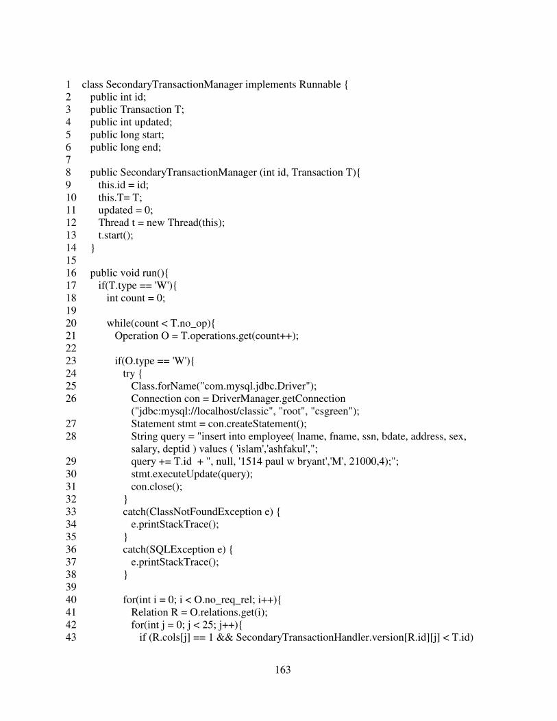
163
1 class SecondaryTransactionManager implements Runnable {
2 public int id;
3 public Transaction T;
4 public int updated;
5 public long start;
6 public long end;
7
8 public SecondaryTransactionManager (int id, Transaction T){
9 this.id = id;
10 this.T= T;
11 updated = 0;
12 Thread t = new Thread(this);
13 t.start();
14 }
15
16 public void run(){
17 if(T.type == 'W'){
18 int count = 0;
19
20 while(count < T.no_op){
21 Operation O = T.operations.get(count++);
22
23 if(O.type == 'W'){
24 try {
25 Class.forName("com.mysql.jdbc.Driver");
26 Connection con = DriverManager.getConnection
("jdbc:mysql://localhost/classic", "root", "csgreen");
27 Statement stmt = con.createStatement();
28 String query = "insert into employee( lname, fname, ssn, bdate, address, sex,
salary, deptid ) values ( 'islam','ashfakul',";
29 query += T.id + ", null, '1514 paul w bryant','M', 21000,4);";
30 stmt.executeUpdate(query);
31 con.close();
32 }
33 catch(ClassNotFoundException e) {
34 e.printStackTrace();
35 }
36 catch(SQLException e) {
37 e.printStackTrace();
38 }
39
40 for(int i = 0; i < O.no_req_rel; i++){
41 Relation R = O.relations.get(i);
42 for(int j = 0; j < 25; j++){
43 if (R.cols[j] == 1 && SecondaryTransactionHandler.version[R.id][j] < T.id)

164
44 SecondaryTransactionHandler.version[R.id][j] = T.id;
45 }
46 }
47 }
48 else{
49 try {
50 Class.forName("com.mysql.jdbc.Driver");
51 Connection con = DriverManager.getConnection
("jdbc:mysql://localhost/classic", "root", "csgreen");
52 Statement stmt = con.createStatement();
53 String query = " select max(rowid) from employee;";
54 ResultSet rs = stmt.executeQuery(query);
55
56 while (rs.next()) {
57 }
58 con.close();
59 }
60 catch(ClassNotFoundException e) {
61 e.printStackTrace();
62 }
63 catch(SQLException e) {
64 e.printStackTrace();
65 }
66 }
67 }
68 Transaction msg = new Transaction();
69 msg.id = T.id;
70 msg.type = 'P';
71 SecondaryTransactionHandler.MessageTrack[1][T.id] = new SendMessage( new byte[]
{(byte)192,(byte)168,(byte)0,(byte)100}, msg, 0.995);
72 }else{
73 int count = 0;
74
75 while(count < T.no_op){
76 Operation O = T.operations.get(count++);
77 boolean flag = true;
78
79 while(true){
80 flag = true;
81 if(flag == true){
82 try {
83 Class.forName("com.mysql.jdbc.Driver");
84 Connection con = DriverManager.getConnection
("jdbc:mysql://localhost/classic", "root", "csgreen");
85 Statement stmt = con.createStatement();
86 String query = " select max(rowid) from employee;";

165
87 ResultSet rs = stmt.executeQuery(query);
88
89 while (rs.next()) {
90 }
91 con.close();
92 }
93 catch(ClassNotFoundException e) {
94 e.printStackTrace();
95 }
96 catch(SQLException e) {
97 e.printStackTrace();
98 }
99 break;
100 }
101 else{
102 try {
103 Thread.sleep(25);
104 } catch (InterruptedException ie) {
105 System.out.println(ie.getMessage());
106 }
107 flag = true;
108 }
109 }
110 }
111 Transaction msg = new Transaction();
112 msg.id = T.id;
113 msg.type = 'P';
114 SecondaryTransactionHandler.MessageTrack[0][T.id] = new SendMessage( new byte[]
{(byte)192,(byte)168,(byte)0,(byte)1}, msg, 0.995);
115 }
116 System.out.println("Transaction " + id + " is executed ");
117 }
118}
QuorumCoordinatorNode Class: This class performs as a coordinator server in the quorum
approach.
1 public class QuorumCoordinatorNode {
2 private ServerSocket server;
3 private int port = 7777;
4 public static Random pathdelay = new Random(1209309834);
5 public static Random pathfailure = new Random(1982308434);

166
6
7 public QuorumCoordinatorNode() {
8 try {
9 server = new ServerSocket(port);
10 } catch (IOException e) {
11 e.printStackTrace();
12 }
13 }
14
15 public static void main(String[] args) {
16 QuorumCoordinatorNode coordinator = new QuorumCoordinatorNode();
17 new CoordinatorTransactionHandler();
18 coordinator.handleConnection();
19 }
20
21 public void handleConnection() {
22 System.out.println("Waiting for client update request");
23 while (true) {
24 try {
25 Socket socket = server.accept();
26 new CoordinatorConnectionHandler(socket);
27 } catch (IOException e) {
28 e.printStackTrace();
29 }
30 }
31 }
32 }
CoordinatorConnectionHandler Class: This class handles the network connections at the
coordinator server end in the quorum approach.
1 class CoordinatorConnectionHandler implements Runnable {
2 private Socket socket;
3
4 public CoordinatorConnectionHandler(Socket socket) {
5 this.socket = socket;
6 Thread t = new Thread(this);
7 t.start();
8 }
9
10 public void run() {
11 try {

167
12 ObjectInputStream ois = new ObjectInputStream(socket.getInputStream());
13 Transaction message = (Transaction) ois.readObject();
14 InetAddress sender = socket.getInetAddress();
15 ois.close();
16 socket.close();
17
18 InetAddress Client = InetAddress.getByAddress(new byte[]
{(byte)192,(byte)168,(byte)0,(byte)1});
19 InetAddress UB1 = InetAddress.getByAddress(new byte[]
{(byte)192,(byte)168,(byte)0,(byte)101});
20 InetAddress UB2 = InetAddress.getByAddress(new byte[]
{(byte)192,(byte)168,(byte)0,(byte)102});
21 InetAddress UB3 = InetAddress.getByAddress(new byte[]
{(byte)192,(byte)168,(byte)0,(byte)103});
22 InetAddress UB4 = InetAddress.getByAddress(new byte[]
{(byte)192,(byte)168,(byte)0,(byte)104});
23 InetAddress UB5 = InetAddress.getByAddress(new byte[]
{(byte)192,(byte)168,(byte)0,(byte)105});
24
25 int delay = 0;
26
27 if(sender.equals(Client))
28 delay = getPathDelay(9);
29 else if (sender.equals(UB1))
30 delay = getPathDelay(15);
31 else if(sender.equals(UB2))
32 delay = getPathDelay(18);
33 else if (sender.equals(UB3))
34 delay = getPathDelay(29);
35 else if(sender.equals(UB4))
36 delay = getPathDelay(32);
37 else if (sender.equals(UB5))
38 delay = getPathDelay(38);
39
40 try {
41 Thread.sleep( (long)delay );
42 } catch (InterruptedException ie) {
43 System.out.println(ie.getMessage());
44 }
45
46 if(message.type == 'A'){
47 if(sender.equals(Client))
48 CoordinatorTransactionHandler.MessageTrack[0][message.id].flag = false;
49 else if (sender.equals(UB1))
50 CoordinatorTransactionHandler.MessageTrack[1][message.id].flag = false;
51 else if(sender.equals(UB2))

168
52 CoordinatorTransactionHandler.MessageTrack[2][message.id].flag = false;
53 else if(sender.equals(UB3))
54 CoordinatorTransactionHandler.MessageTrack[3][message.id].flag = false;
55 else if(sender.equals(UB4))
56 CoordinatorTransactionHandler.MessageTrack[4][message.id].flag = false;
57 else if(sender.equals(UB5))
58 CoordinatorTransactionHandler.MessageTrack[5][message.id].flag = false;
59 }
60 else if (message.type == 'S'){
61 Transaction msg = new Transaction();
62 msg.id = message.id;
63 msg.type = 'A';
64 new SendMessage(sender.getAddress(), msg, 0.995);
65 CoordinatorTransactionHandler.freeLock(message);
66 CoordinatorTransactionHandler.queue[message.id].updated = 5;
67 }
68 else {
69 Transaction msg = new Transaction();
70 msg.id = message.id;
71 msg.type = 'A';
72 new SendMessage(sender.getAddress(), msg, 0.995);
73
74 if(sender.equals(Client) && !CoordinatorTransactionHandler.flag[message.id]) {
75 CoordinatorTransactionHandler.flag[message.id] = true;
76 CoordinatorTransactionHandler.queue[message.id] = new
QUB0TransactionManager(message.id, message);
77 }
78 else if(message.type == 'P') {
79 CoordinatorTransactionHandler.queue[message.id].updated++;
80 }
81 }
82 } catch (IOException e) {
83 e.printStackTrace();
84 } catch (ClassNotFoundException e) {
85 e.printStackTrace();
86 }
87 }
88
89 int getPathDelay(int seed){
90 double rand = QuorumCoordinatorNode.pathdelay.nextDouble();
91 int delay = 0;
92
93 if(rand < .4)
94 delay = seed;
95 else if (rand <.8)
96 delay = seed + 1;

169
97 else if(rand < .9)
98 delay = (int) (seed + seed * .2);
99 else if(rand < .95)
100 delay = (int) (seed + 40 * .4);
101 else if(rand < .99)
102 delay = (int) (seed + 40 * .8);
103 else
104 delay = seed + 50 ;
105
106 return delay;
107 }
108 }
CoordinatorTransactionHandler Class: This class handles the transaction requests at the
coordinator server end in the quorum approach.
1 class CoordinatorTransactionHandler implements Runnable {
2 public static final int notr = 2000;
3 public static CoordinatorTransactionManager []queue = new
CoordinatorTransactionManager[notr];
4 public static int [][]lock = new int[45][25];
5 public static boolean []flag = new boolean[notr];
6 public static SendMessage [][]MessageTrack = new SendMessage[6][notr];
7
8 public CoordinatorTransactionHandler() {
9 Thread t = new Thread(this);
10 for(int i = 0; i < 45; i++)
11 for(int j = 0; j < 25; j++)
12 lock[i][j] = -1;
13 for(int i=0; i<notr;i++)
14 flag[i] = false;
15 t.start();
16 }
17
18 public void run() {
19
20 }
21
22 public static synchronized boolean freeLock(Transaction T){
23 for(int i = 0; i < T.no_op; i++){
24 Operation O = T.operations.get(i);
25 for(int j = 0; j < O.no_req_rel; j++){

170
26 Relation R = O.relations.get(j);
27 for(int k = 0; k < 25 ; k++){
28 if(R.cols[k] == 1 && CoordinatorTransactionHandler.lock[R.id][k] == T.id){
29 CoordinatorTransactionHandler.lock[R.id][k] = -1;
30 }
31 }
32 }
33 }
34 return true;
35 }
36
37 public static synchronized int acquireLock(Transaction T){
38 for(int i = 0; i < T.no_op; i++){
39 Operation O = T.operations.get(i);
40 for(int j = 0; j < O.no_req_rel; j++){
41 Relation R = O.relations.get(j);
42 for(int k = 0; k < 25; k++){
43 if(O.type == 'W' && R.cols[k] == 1){
44 if(CoordinatorTransactionHandler.lock[R.id][k] == -1 ||
CoordinatorTransactionHandler.lock[R.id][k] == T.id){
45 CoordinatorTransactionHandler.lock[R.id][k] = T.id;
46 }
47 else{
48 freeLock(T);
49 return CoordinatorTransactionHandler.lock[R.id][k];
50 }
51 }
52 else if(R.cols[k] == 1){
53 if(CoordinatorTransactionHandler.lock[R.id][k] == -1 ||
CoordinatorTransactionHandler.lock[R.id][k] == T.id){
54 }
55 else{
56 freeLock(T);
57 return CoordinatorTransactionHandler.lock[R.id][k];
58 }
59 }
60 }
61 }
62 }
63 return T.id;
64 }
65 }

171
CoordinatorTransactionManager Class: This class performs the tasks of a typical
transaction manager at the coordinator server end in the quorum approach.
1 class CoordinatorTransactionManager implements Runnable {
2 public int id;
3 public Transaction T;
4 public int updated;
5 public long start;
6 public long end;
7
8 public CoordinatorTransactionManager (int id, Transaction T){
9 this.id = id;
10 this.T= T;
11 updated = 0;
12 Thread t = new Thread(this);
13 t.start();
14 }
15
16 public void run(){
17 int id_lock = 0;
18
19 while(true){
20 if((id_lock = CoordinatorTransactionHandler.acquireLock(T)) != id){
21 if(id < id_lock) {
22 try {
23 Thread.sleep(25);
24 } catch (InterruptedException ie) {
25 System.out.println(ie.getMessage());
26 }
27 }
28 else{
29 T.type = 'S';
30 T.restarted++;
31 CoordinatorTransactionHandler.MessageTrack[0][T.id] = new SendMessage(
new byte[] {(byte)192,(byte)168,(byte)0,(byte)1}, T, 0.995);
32 CoordinatorTransactionHandler.flag[T.id] = false;
33 return;
34 }
35 }
36 else
37 break;
38 }

172
39 CoordinatorTransactionHandler.MessageTrack[1][T.id] = new SendMessage( new
byte[] {(byte)192,(byte)168,(byte)0,(byte)101}, T, 0.995);
40 CoordinatorTransactionHandler.MessageTrack[2][T.id] = new SendMessage( new
byte[] {(byte)192,(byte)168,(byte)0,(byte)102}, T, 0.995);
41 CoordinatorTransactionHandler.MessageTrack[3][T.id] = new SendMessage( new
byte[] {(byte)192,(byte)168,(byte)0,(byte)103}, T, 0.995);
42 CoordinatorTransactionHandler.MessageTrack[4][T.id] = new SendMessage( new
byte[] {(byte)192,(byte)168,(byte)0,(byte)104}, T, 0.995);
43 CoordinatorTransactionHandler.MessageTrack[5][T.id] = new SendMessage( new
byte[] {(byte)192,(byte)168,(byte)0,(byte)105}, T, 0.995);
44
45 int count = 0;
46
47 while(count < T.no_op){
48 Operation O = T.operations.get(count++);
49
50 if(O.type == 'W'){
51 try {
52 Class.forName("com.mysql.jdbc.Driver");
53 Connection con = DriverManager.getConnection
("jdbc:mysql://localhost/classic", "root", "csgreen");
54 Statement stmt = con.createStatement();
55 String query = "insert into employee( lname, fname, ssn, bdate, address, sex,
salary, deptid ) values ( 'islam','ashfakul',";
56 query += T.id + ", null, '1514 paul w bryant','M', 21000,4);";
57 stmt.executeUpdate(query);
58 con.close();
59 }catch(ClassNotFoundException e) {
60 e.printStackTrace();
61 }catch(SQLException e) {
62 e.printStackTrace();
63 }
64 }
65 else{
66 try {
67 Class.forName("com.mysql.jdbc.Driver");
68 Connection con = DriverManager.getConnection
("jdbc:mysql://localhost/classic", "root", "csgreen");
69 Statement stmt = con.createStatement();
70 String query = " select max(rowid) from employee;";
71 ResultSet rs = stmt.executeQuery(query);
72
73 while (rs.next()) {
74 }
75 con.close();
76 }catch(ClassNotFoundException e) {

173
77 e.printStackTrace();
78 }catch(SQLException e) {
79 e.printStackTrace();
80 }
81 }
82 }
83
84 while(updated < 3){
85 }
86 CoordinatorTransactionHandler.freeLock(T);
87 Transaction msg = new Transaction();
88 msg.id = T.id;
89 msg.type = 'P';
90 CoordinatorTransactionHandler.MessageTrack[0][T.id] = new SendMessage( new
byte[] {(byte)192,(byte)168,(byte)0,(byte)1}, msg, 0.995);
91 System.out.println("Transaction " + id + " is executed. ");
92 }
93 }
QuorumParticipatorNode Class: This class performs as the participator server in the
quorum approach.
1 public class QuorumParticipatorNode {
2 private ServerSocket server;
3 private int port = 7777;
4 public static Random pathdelay = new Random(230938495);
5 public static Random pathfailure = new Random(2093485823);
6
7 public QuorumParticipatorNode() {
8 try {
9 server = new ServerSocket(port);
10 } catch (IOException e) {
11 e.printStackTrace();
12 }
13 }
14
15 public static void main(String[] args) {
16 QuorumParticipatorNode participator = new QuorumParticipatorNode();
17 new ParticipatorTransactionHandler();
18 participator.handleConnection();
19 }

174
20
21 public void handleConnection() {
22 System.out.println("Waiting for client update request");
23 while (true) {
24 try {
25 Socket socket = server.accept();
26 new ParticipatorConnectionHandler(socket);
27 } catch (IOException e) {
28 e.printStackTrace();
29 }
30 }
31 }
32 }
ParticipatorConnectionHandler Class: This class handles the network connections at the
participator server end in the quorum approach.
1 class ParticipatorConnectionHandler implements Runnable {
2 private Socket socket;
3
4 public ParticipatorConnectionHandler(Socket socket) {
5 this.socket = socket;
6 Thread t = new Thread(this);
7 t.start();
8 }
9
10 public void run() {
11 try {
12 ObjectInputStream ois = new ObjectInputStream(socket.getInputStream());
13 Transaction message = (Transaction) ois.readObject();
14 InetAddress sender = socket.getInetAddress();
15 ois.close();
16 socket.close();
17
18 InetAddress Client = InetAddress.getByAddress(new byte[]
{(byte)192,(byte)168,(byte)0,(byte)1});
19 InetAddress UB0 = InetAddress.getByAddress(new byte[]
{(byte)192,(byte)168,(byte)0,(byte)100});
20 InetAddress UB2 = InetAddress.getByAddress(new byte[]
{(byte)192,(byte)168,(byte)0,(byte)102});
21 InetAddress UB3 = InetAddress.getByAddress(new byte[]
{(byte)192,(byte)168,(byte)0,(byte)103});

175
22 InetAddress UB4 = InetAddress.getByAddress(new byte[]
{(byte)192,(byte)168,(byte)0,(byte)104});
23 InetAddress UB5 = InetAddress.getByAddress(new byte[]
{(byte)192,(byte)168,(byte)0,(byte)105});
24
25 int delay = 0;
26
27 if(sender.equals(Client))
28 delay = getPathDelay(13);
29 else if (sender.equals(UB0))
30 delay = getPathDelay(15);
31 else if(sender.equals(UB2))
32 delay = getPathDelay(26);
33 else if (sender.equals(UB3))
34 delay = getPathDelay(14);
35 else if(sender.equals(UB4))
36 delay = getPathDelay(29);
37 else if (sender.equals(UB5))
38 delay = getPathDelay(40);
39
40 try {
41 Thread.sleep( (long)delay );
42 } catch (InterruptedException ie) {
43 System.out.println(ie.getMessage());
44 }
45
46 if(message.type == 'A'){
47 if(sender.equals(Client))
48 ParticipatorTransactionHandler.MessageTrack[0][message.id].flag = false;
49 else if (sender.equals(UB0))
50 ParticipatorTransactionHandler.MessageTrack[1][message.id].flag = false;
51 else if (sender.equals(UB2))
52 ParticipatorTransactionHandler.MessageTrack[2][message.id].flag = false;
53 else if (sender.equals(UB3))
54 ParticipatorTransactionHandler.MessageTrack[3][message.id].flag = false;
55 else if (sender.equals(UB4))
56 ParticipatorTransactionHandler.MessageTrack[4][message.id].flag = false;
57 else if (sender.equals(UB5))
58 ParticipatorTransactionHandler.MessageTrack[5][message.id].flag = false;
59 }
60 else {
61 Transaction msg = new Transaction();
62 msg.id = message.id;
63 msg.type = 'A';
64 new SendMessage(sender.getAddress(), msg, 0.995);

176
65 if(sender.equals(Client) && !ParticipatorTransactionHandler.flag[message.id]){
66 ParticipatorTransactionHandler.flag[message.id] = true;
67 ParticipatorTransactionHandler.queue[message.id] = new
QUB1TransactionManager(message.id, message);
68 ParticipatorTransactionHandler.queue[message.id].coordinator = true;
69 ParticipatorTransactionHandler.queue[message.id].sender = sender;
70 }else if((message.type == 'W' || message.type == 'R') &&
!ParticipatorTransactionHandler.flag[message.id]){
71 ParticipatorTransactionHandler.flag[message.id] = true;
72 ParticipatorTransactionHandler.queue[message.id] = new
QUB1TransactionManager(message.id, message);
73 ParticipatorTransactionHandler.queue[message.id].sender = sender;
74 }
75 else if(message.type == 'P'){
76 ParticipatorTransactionHandler.queue[message.id].updated++;
77 }
78 }
79 } catch (IOException e) {
80 e.printStackTrace();
81 } catch (ClassNotFoundException e) {
82 e.printStackTrace();
83 }
84 }
85
86 int getPathDelay(int seed){
87 double rand = QuorumParticipatorNode.pathdelay.nextDouble();
88 int delay = 0;
89
90 if(rand < .4)
91 delay = seed;
92 else if (rand <.8)
93 delay = seed + 1;
94 else if(rand < .9)
95 delay = (int) (seed + seed * .2);
96 else if(rand < .95)
97 delay = (int) (seed + 40 * .4);
98 else if(rand < .99)
99 delay = (int) (seed + 40 * .8);
100 else
101 delay = seed + 50 ;
102
103 return delay;
104 }
105 }

177
ParticipatorTransactionHandler Class: This class handles the transaction requests at the
participator sever end in the quorum approach.
1 class ParticipatorTransactionHandler implements Runnable {
2 public static final int notr = 2000;
3 public static QUB1TransactionManager []queue = new
ParticipatorTransactionManager[notr];
4 public static int [][]version = new int[45][25];
5 public static boolean []flag = new boolean[notr];
6 public static SendMessage [][]MessageTrack = new SendMessage[6][notr];
7
8 public ParticipatorTransactionHandler() {
9 Thread t = new Thread(this);
10 for(int i = 0; i < 45; i++)
11 for(int j = 0; j < 25; j++)
12 version[i][j] = -1;
13 for(int i=0; i<notr;i++)
14 flag[i] = false;
15 t.start();
16 }
17
18 public void run() {
19 }
20 }
ParticipatorTransactionManager Class: This class performs the jobs of a typical
transaction manager at the participator server end in the quorum approach.
1 class ParticipatorTransactionManager implements Runnable {
2 public int id;
3 public Transaction T;
4 public int updated;
5 public long start;
6 public long end;
7 public boolean coordinator;
8 public InetAddress sender;
9
10 public ParticipatorTransactionManager (int id, Transaction T){
11 this.id = id;

178
12 this.T= T;
13 updated = 0;
14 coordinator = false;
15 Thread t = new Thread(this);
16 t.start();
17 }
18
19 public void run(){
20 if(coordinator == true){
21 ParticipatorTransactionHandler.MessageTrack[2][T.id] = new SendMessage( new
byte[] {(byte)192,(byte)168,(byte)0,(byte)102}, T, 0.995);
22 ParticipatorTransactionHandler.MessageTrack[3][T.id] = new SendMessage( new
byte[] {(byte)192,(byte)168,(byte)0,(byte)103}, T, 0.995);
23 }
24
25 if(T.type == 'W'){
26 int count = 0;
27
28 while(count < T.no_op){
29 Operation O = T.operations.get(count++);
30 if(O.type == 'W'){
31 try {
32 Class.forName("com.mysql.jdbc.Driver");
33 Connection con = DriverManager.getConnection
("jdbc:mysql://localhost/quorum", "root", "csgreen");
34 Statement stmt = con.createStatement();
35 String query = "insert into employee( lname, fname, ssn, bdate, address, sex,
salary, deptid ) values ( 'islam','ashfakul',";
36 query += T.id + ", null, '1514 paul w bryant','M', 21000,4);";
37 stmt.executeUpdate(query);
38 con.close();
39 }
40 catch(ClassNotFoundException e) {
41 e.printStackTrace();
42 }
43 catch(SQLException e) {
44 e.printStackTrace();
45 }
46
47 for(int i = 0; i < O.no_req_rel; i++){
48 Relation R = O.relations.get(i);
49 for(int j = 0; j < 25; j++){
50 if (R.cols[j] == 1 && ParticipatorTransactionHandler.version[R.id][j] < T.id)
51 ParticipatorTransactionHandler.version[R.id][j] = T.id;
52 }
53 }

179
54 }
55 else{
56 try {
57 Class.forName("com.mysql.jdbc.Driver");
58 Connection con = DriverManager.getConnection
("jdbc:mysql://localhost/quorum", "root", "csgreen");
59 Statement stmt = con.createStatement();
60 String query = " select max(rowid) from employee;";
61 ResultSet rs = stmt.executeQuery(query);
62
63 while (rs.next()) {
64 }
65 con.close();
66 }
67 catch(ClassNotFoundException e) {
68 e.printStackTrace();
69 }
70 catch(SQLException e) {
71 e.printStackTrace();
72 }
73 }
74 }
75 }
76 else{
77 int count = 0;
78
79 while(count < T.no_op){
80 Operation O = T.operations.get(count++);
81 boolean flag = true;
82
83 while(true){
84 for(int i = 0; i < O.no_req_rel; i++){
85 int vrsn = -1;
86 Relation R = O.relations.get(i);
87 for(int j = 0; j < 25; j++){
88 if(R.cols[j] == 1 && ParticipatorTransactionHandler.version[R.id][j] > vrsn){
89 vrsn = ParticipatorTransactionHandler.version[R.id][j];
90 }
91 }
92
93 if(R.vrsn > vrsn){
94 flag = false;
95 break;
96 }
97 }
98

180
99 if(flag == true){
100 try {
101 Class.forName("com.mysql.jdbc.Driver");
102 Connection con = DriverManager.getConnection
("jdbc:mysql://localhost/quorum", "root", "csgreen");
103 Statement stmt = con.createStatement();
104 String query = " select max(rowid) from employee;";
105 ResultSet rs = stmt.executeQuery(query);
106
107 while (rs.next()) {
108 }
109 con.close();
110 }
111 catch(ClassNotFoundException e) {
112 e.printStackTrace();
113 }
114 catch(SQLException e) {
115 e.printStackTrace();
116 }
117 break;
118 }
119 else{
120 try {
121 Thread.sleep(25);
122 } catch (InterruptedException ie) {
123 System.out.println(ie.getMessage());
124 }
125 flag = true;
126 }
127 }
128 }
129
130 if(coordinator)
131 while(updated < 2){
132 }
133 }
134
135
136 try{
137 InetAddress Client = InetAddress.getByAddress(new byte[]
{(byte)192,(byte)168,(byte)0,(byte)1});
138 InetAddress UB0 = InetAddress.getByAddress(new byte[]
{(byte)192,(byte)168,(byte)0,(byte)100});
139 InetAddress UB2 = InetAddress.getByAddress(new byte[]
{(byte)192,(byte)168,(byte)0,(byte)102});

181
140 InetAddress UB3 = InetAddress.getByAddress(new byte[]
{(byte)192,(byte)168,(byte)0,(byte)103});
141 InetAddress UB4 = InetAddress.getByAddress(new byte[]
{(byte)192,(byte)168,(byte)0,(byte)104});
142 InetAddress UB5 = InetAddress.getByAddress(new byte[]
{(byte)192,(byte)168,(byte)0,(byte)105});
143
144 Transaction msg = new Transaction();
145 msg.id = T.id;
146 msg.type = 'P';
147
148 if(sender.equals(Client))
149 ParticipatorTransactionHandler.MessageTrack[0][T.id] = new SendMessage(
sender.getAddress(), msg, 0.995);
150 else if (sender.equals(UB0))
151 ParticipatorTransactionHandler.MessageTrack[1][T.id] = new SendMessage(
sender.getAddress(), msg, 0.995);
152 else if(sender.equals(UB2))
153 ParticipatorTransactionHandler.MessageTrack[2][T.id] = new SendMessage(
sender.getAddress(), msg, 0.995);
154 else if (sender.equals(UB3))
155 ParticipatorTransactionHandler.MessageTrack[3][T.id] = new SendMessage(
sender.getAddress(), msg, 0.995);
156 else if(sender.equals(UB4))
157 ParticipatorTransactionHandler.MessageTrack[4][T.id] = new SendMessage(
sender.getAddress(), msg, 0.995);
158 else if (sender.equals(UB5))
159 ParticipatorTransactionHandler.MessageTrack[5][T.id] = new SendMessage(
sender.getAddress(), msg, 0.995);
160 }catch(Exception e){
161 System.out.println(ie.getMessage());
162 }
163 System.out.println("Transaction " + id + " is executed ");
164 }
165 }
TreeRootNode Class: This class performs the tasks of the root node in the TBC approach.
1 public class TreeRootNode {
2 private ServerSocket server;
3 private int port = 7777;
4 public static Random pathdelay = new Random(1209309834);
5 public static Random pathfailure = new Random(1982308434);

182
6
7 public TreeRootNode() {
8 try {
9 server = new ServerSocket(port);
10 } catch (IOException e) {
11 e.printStackTrace();
12 }
13 }
14
15 public static void main(String[] args) {
16 TreeRootNode root = new TreeRootNode();
17 new RootTransactionHandler();
18 root.handleConnection();
19 }
20
21 public void handleConnection() {
22 System.out.println("Waiting for client update request");
23 while (true) {
24 try {
25 Socket socket = server.accept();
26 new RootConnectionHandler(socket);
27 } catch (IOException e) {
28 e.printStackTrace();
29 }
30 }
31 }
32 }
RootConnectionHandler Class: This class handles the network connections at the root
server end in the TBC approach.
1 class RootConnectionHandler implements Runnable {
2 private Socket socket;
3
4 public RootConnectionHandler(Socket socket) {
5 this.socket = socket;
6 Thread t = new Thread(this);
7 t.start();
8 }
9
10 public void run() {
11 try {

183
12 ObjectInputStream ois = new ObjectInputStream(socket.getInputStream());
13 Transaction message = (Transaction) ois.readObject();
14 InetAddress sender = socket.getInetAddress();
15 ois.close();
16 socket.close();
17
18 InetAddress Client = InetAddress.getByAddress(new byte[]
{(byte)192,(byte)168,(byte)0,(byte)1});
19 InetAddress UB1 = InetAddress.getByAddress(new byte[]
{(byte)192,(byte)168,(byte)0,(byte)101});
20 InetAddress UB2 = InetAddress.getByAddress(new byte[]
{(byte)192,(byte)168,(byte)0,(byte)102});
21
22 int delay = 0;
23
24 if(sender.equals(Client))
25 delay = getPathDelay(9);
26 else if (sender.equals(UB1))
27 delay = getPathDelay(15);
28 else if(sender.equals(UB2))
29 delay = getPathDelay(18);
30
31 try {
32 Thread.sleep( (long)delay );
33 } catch (InterruptedException ie) {
34 System.out.println(ie.getMessage());
35 }
36
37 if(message.type == 'A'){
38 if(sender.equals(Client))
39 RootTransactionHandler.MessageTrack[0][message.id].flag = false;
40 else if (sender.equals(UB1))
41 RootTransactionHandler.MessageTrack[1][message.id].flag = false;
42 else if(sender.equals(UB2))
43 RootTransactionHandler.MessageTrack[2][message.id].flag = false;
44 }
45 else if (message.type == 'S'){
46 Transaction msg = new Transaction();
47 msg.id = message.id;
48 msg.type = 'A';
49 new TUB0SendMessage(sender.getAddress(), msg, 0.995);
50 RootTransactionHandler.freeLock(message);
51 RootTransactionHandler.queue[message.id].updated = 2;
52 }
53 else {
54 Transaction msg = new Transaction();

184
55 msg.id = message.id;
56 msg.type = 'A';
57 new TUB0SendMessage(sender.getAddress(), msg, 0.995);
58
59 if(sender.equals(Client) && !RootTransactionHandler.flag[message.id]){
60 RootTransactionHandler.flag[message.id] = true;
61 RootTransactionHandler.queue[message.id] = new
TUB0TransactionManager(message.id, message);
62 }else if(message.type == 'P'){
63 RootTransactionHandler.queue[message.id].updated++;
64 }
65 }
66 } catch (IOException e) {
67 e.printStackTrace();
68 } catch (ClassNotFoundException e) {
69 e.printStackTrace();
70 }
71 }
72
73 int getPathDelay(int seed){
74 double rand = TreeRootNode.pathdelay.nextDouble();
75 int delay = 0;
76 if(rand < .4)
77 delay = seed;
78 else if (rand <.8)
79 delay = seed + 1;
80 else if(rand < .9)
81 delay = (int) (seed + seed * .2);
82 else if(rand < .95)
83 delay = (int) (seed + 40 * .4);
84 else if(rand < .99)
85 delay = (int) (seed + 40 * .8);
86 else
87 delay = seed + 50 ;
88
89 return delay;
90 }
91 }
RootTransactionHandler Class: This class handles the transaction requests at the root
server end in the TBC approach.
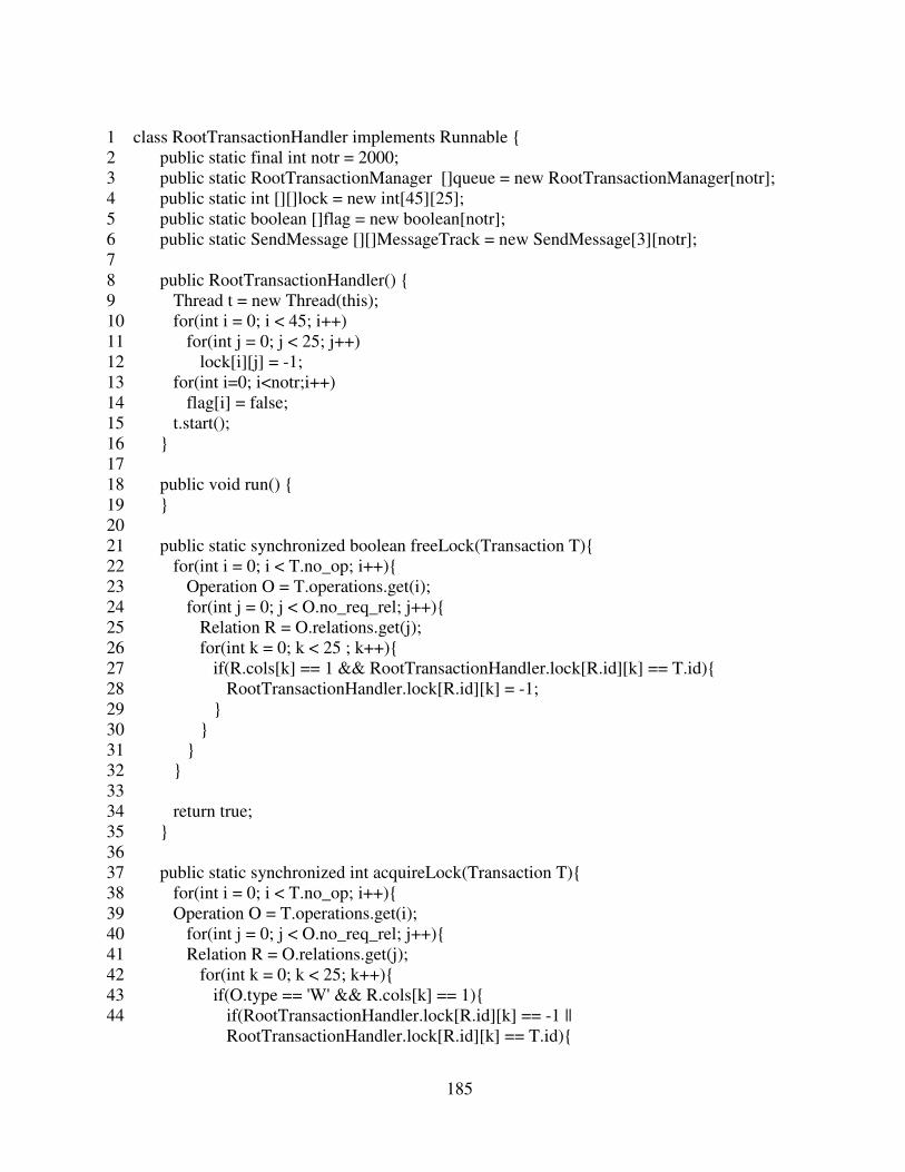
185
1 class RootTransactionHandler implements Runnable {
2 public static final int notr = 2000;
3 public static RootTransactionManager []queue = new RootTransactionManager[notr];
4 public static int [][]lock = new int[45][25];
5 public static boolean []flag = new boolean[notr];
6 public static SendMessage [][]MessageTrack = new SendMessage[3][notr];
7
8 public RootTransactionHandler() {
9 Thread t = new Thread(this);
10 for(int i = 0; i < 45; i++)
11 for(int j = 0; j < 25; j++)
12 lock[i][j] = -1;
13 for(int i=0; i<notr;i++)
14 flag[i] = false;
15 t.start();
16 }
17
18 public void run() {
19 }
20
21 public static synchronized boolean freeLock(Transaction T){
22 for(int i = 0; i < T.no_op; i++){
23 Operation O = T.operations.get(i);
24 for(int j = 0; j < O.no_req_rel; j++){
25 Relation R = O.relations.get(j);
26 for(int k = 0; k < 25 ; k++){
27 if(R.cols[k] == 1 && RootTransactionHandler.lock[R.id][k] == T.id){
28 RootTransactionHandler.lock[R.id][k] = -1;
29 }
30 }
31 }
32 }
33
34 return true;
35 }
36
37 public static synchronized int acquireLock(Transaction T){
38 for(int i = 0; i < T.no_op; i++){
39 Operation O = T.operations.get(i);
40 for(int j = 0; j < O.no_req_rel; j++){
41 Relation R = O.relations.get(j);
42 for(int k = 0; k < 25; k++){
43 if(O.type == 'W' && R.cols[k] == 1){
44 if(RootTransactionHandler.lock[R.id][k] == -1 ||
RootTransactionHandler.lock[R.id][k] == T.id){

186
45 RootTransactionHandler.lock[R.id][k] = T.id;
46 }
47 else{
48 freeLock(T);
49 return RootTransactionHandler.lock[R.id][k];
50 }
51 }
52 else if(R.cols[k] == 1){
53 if(RootTransactionHandler.lock[R.id][k] == -1 ||
RootTransactionHandler.lock[R.id][k] == T.id){
54 }
55 else{
56 freeLock(T);
57 return RootTransactionHandler.lock[R.id][k];
58 }
59 }
60 }
61 }
62 }
63
64 return T.id;
65 }
66 }
RootTransactionManager Class: This class performs the tasks of a typical transaction
manager at the root server end in the TBC approach.
1 class RootTransactionManager implements Runnable {
2 public int id;
3 public Transaction T;
4 public int updated;
5 public long start;
6 public long end;
7
8 public RootTransactionManager (int id, Transaction T){
9 this.id = id;
10 this.T= T;
11 updated = 0;
12 Thread t = new Thread(this);
13 t.start();
14 }
15

187
16 public void run(){
17 int id_lock = 0;
18
19 while(true){
20 if((id_lock = RootTransactionHandler.acquireLock(T)) != id){
21 if(id < id_lock) {
22 try {
23 Thread.sleep(25);
24 } catch (InterruptedException ie) {
25 System.out.println(ie.getMessage());
26 }
27 }
28 else{
29 T.type = 'S';
30 T.restarted++;
31 RootTransactionHandler.MessageTrack[0][T.id] = new SendMessage( new byte[]
{(byte)192,(byte)168,(byte)0,(byte)1}, T, 0.995);
32 RootTransactionHandler.flag[T.id] = false;
33 return;
34 }
35 }
36 else
37 break;
38 }
39
40 RootTransactionHandler.MessageTrack[1][T.id] = new SendMessage( new byte[]
{(byte)192,(byte)168,(byte)0,(byte)101}, T, 0.995);
41 RootTransactionHandler.MessageTrack[2][T.id] = new SendMessage( new byte[]
{(byte)192,(byte)168,(byte)0,(byte)102}, T, 0.995);
42 int count = 0;
43
44 while(count < T.no_op){
45 Operation O = T.operations.get(count++);
46 if(O.type == 'W'){
47 try {
48 Class.forName("com.mysql.jdbc.Driver");
49 Connection con = DriverManager.getConnection ("jdbc:mysql://localhost/tbc",
"root", "csgreen");
50 Statement stmt = con.createStatement();
51 String query = "insert into employee( lname, fname, ssn, bdate, address, sex,
salary, deptid ) values ( 'islam','ashfakul',";
52 query += T.id + ", null, '1514 paul w bryant','M', 21000,4);";
53 stmt.executeUpdate(query);
54 con.close();
55 } catch(ClassNotFoundException e) {
56 e.printStackTrace();

188
57 }
58 catch(SQLException e) {
59 e.printStackTrace();
60 }
61 }
62 else{
63 try {
64 Class.forName("com.mysql.jdbc.Driver");
65 Connection con = DriverManager.getConnection ("jdbc:mysql://localhost/tbc",
"root", "csgreen");
66 Statement stmt = con.createStatement();
67 String query = " select max(rowid) from employee;";
68 ResultSet rs = stmt.executeQuery(query);
69 while (rs.next()) {
70 }
71 con.close();
72 }
73 catch(ClassNotFoundException e) {
74 e.printStackTrace();
75 }
76 catch(SQLException e) {
77 e.printStackTrace();
78 }
79 }
80 }
81
82 while(updated <2){
83 }
84
85 RootTransactionHandler.freeLock(T);
86 Transaction msg = new Transaction();
87 msg.id = T.id;
88 msg.type = 'P';
89 RootTransactionHandler.MessageTrack[0][T.id] = new SendMessage( new byte[]
{(byte)192,(byte)168,(byte)0,(byte)1}, msg, 0.995);
90 start = System.nanoTime();
91 System.out.println("Transaction " + id + " is executed. ");
92 }
93 }
TreePrimaryChildNode Class: This class performs as the primary child server in the TBC
approach.

189
1 public class TreePrimaryChildNode {
2 private ServerSocket server;
3 private int port = 7777;
4 public static Random pathdelay = new Random(230938495);
5 public static Random pathfailure = new Random(2093485823);
6
7 public TreePrimaryChildNode() {
8 try {
9 server = new ServerSocket(port);
10 } catch (IOException e) {
11 e.printStackTrace();
12 }
13 }
14
15 public static void main(String[] args) {
16 TreePrimaryChildNode primarychild = new TreePrimaryChildNode();
17 new PrimaryChildTransactionHandler();
18 primarychild.handleConnection();
19 }
20
21 public void handleConnection() {
22 System.out.println("Waiting for client update request");
23
24 while (true) {
25 try {
26 Socket socket = server.accept();
27 new PrimaryChildConnectionHandler(socket);
28 } catch (IOException e) {
29 e.printStackTrace();
30 }
31 }
32 }
33 }
PrimaryChildConnectionHandler Class: This class handles the network connections at the
primary child server end in the TBC approach.
1 class PrimaryChildConnectionHandler implements Runnable {
2 private Socket socket;
3
4 public PrimaryChildConnectionHandler(Socket socket) {

190
5 this.socket = socket;
6 Thread t = new Thread(this);
7 t.start();
8 }
9
10 public void run() {
11 try {
12 ObjectInputStream ois = new ObjectInputStream(socket.getInputStream());
13 Transaction message = (Transaction) ois.readObject();
14 InetAddress sender = socket.getInetAddress();
15 ois.close();
16 socket.close();
17
18 InetAddress Client = InetAddress.getByAddress(new byte[]
{(byte)192,(byte)168,(byte)0,(byte)1});
19 InetAddress UB0 = InetAddress.getByAddress(new byte[]
{(byte)192,(byte)168,(byte)0,(byte)100});
20 InetAddress UB3 = InetAddress.getByAddress(new byte[]
{(byte)192,(byte)168,(byte)0,(byte)103});
21
22 int delay = 0;
23
24 if(sender.equals(Client))
25 delay = getPathDelay(13);
26 else if (sender.equals(UB0))
27 delay = getPathDelay(15);
28 else if(sender.equals(UB3))
29 delay = getPathDelay(14);
30
31 try {
32 Thread.sleep( (long)delay );
33 } catch (InterruptedException ie) {
34 }
35
36 if(message.type == 'A'){
37 if(sender.equals(Client))
38 PrimaryChildTransactionHandler.MessageTrack[0][message.id].flag = false;
39 else if (sender.equals(UB0))
40 PrimaryChildTransactionHandler.MessageTrack[1][message.id].flag = false;
41 else if(sender.equals(UB3))
42 PrimaryChildTransactionHandler.MessageTrack[2][message.id].flag = false;
43 }
44 else {
45 Transaction msg = new Transaction();
46 msg.id = message.id;
47 msg.type = 'A';

191
48 new SendMessage(sender.getAddress(), msg, 0.995);
49
50 if(sender.equals(Client) && !PrimaryChildTransactionHandler.flag[message.id]){
51 PrimaryChildTransactionHandler.flag[message.id] = true;
52 PrimaryChildTransactionHandler.queue[message.id] = new
PrimaryChildTransactionManager(message.id, message);
53 }else if(sender.equals(UB0) &&
!PrimaryChildTransactionHandler.flag[message.id]){
54 PrimaryChildTransactionHandler.flag[message.id] = true;
55 PrimaryChildTransactionHandler.queue[message.id] = new
PrimaryChildTransactionManager(message.id, message);
56 }else{
57 PrimaryChildTransactionHandler.queue[message.id].updated++;
58 }
59 }
60 } catch (IOException e) {
61 e.printStackTrace();
62 } catch (ClassNotFoundException e) {
63 e.printStackTrace();
64 }
65 }
66
67 int getPathDelay(int seed){
68 double rand = TreePrimaryChildNode.pathdelay.nextDouble();
69 int delay = 0;
70
71 if(rand < .4)
72 delay = seed;
73 else if (rand <.8)
74 delay = seed + 1;
75 else if(rand < .9)
76 delay = (int) (seed + seed * .2);
77 else if(rand < .95)
78 delay = (int) (seed + 40 * .4);
79 else if(rand < .99)
80 delay = (int) (seed + 40 * .8);
81 else
82 delay = seed + 50 ;
83
84 return delay;
85 }
86 }

192
PrimaryChildTransactionHandler Class: This class handles the transaction requests at
primary child server end in the TBC approach.
1 class PrimaryChildTransactionHandler implements Runnable {
2 public static final int notr = 2000;
3 public static PrimaryChildTransactionManager []queue = new
PrimaryChildTransactionManager[notr];
4 public static int [][]version = new int[45][25];
5 public static boolean []flag = new boolean[notr];
6 public static SendMessage [][]MessageTrack = new SendMessage[3][notr];
7
8 public PrimaryChildTransactionHandler() {
9 Thread t = new Thread(this);
10
11 for(int i = 0; i < 45; i++)
12 for(int j = 0; j < 25; j++)
13 version[i][j] = -1;
14 for(int i=0; i<notr;i++)
15 flag[i] = false;
16 t.start();
17 }
18
19 public void run() {
20 }
21 }
PrimaryChildTransactionManager Class: This class performs the jobs of a typical
transaction manager at the primary child server end in the TBC approach.
1 class PrimaryChildTransactionManager implements Runnable {
2 public int id;
3 public Transaction T;
4 public int updated;
5 public long start;
6 public long end;
7
8 public PrimaryChildTransactionManager (int id, Transaction T){
9 this.id = id;
10 this.T= T;
11 updated = 0;

193
12 Thread t = new Thread(this);
13 t.start();
14 }
15
16
17 public void run(){
18 if(T.type == 'W'){
19 PrimaryChildTransactionHandler.MessageTrack[2][T.id] = new SendMessage( new
byte[] {(byte)192,(byte)168,(byte)0,(byte)103}, T, 0.995);
20
21 int count = 0;
22
23 while(count < T.no_op){
24 Operation O = T.operations.get(count++);
25
26 if(O.type == 'W'){
27 try {
28 Class.forName("com.mysql.jdbc.Driver");
29 Connection con = DriverManager.getConnection ("jdbc:mysql://localhost/tbc",
"root", "csgreen");
30 Statement stmt = con.createStatement();
31 String query = "insert into employee( lname, fname, ssn, bdate, address, sex,
salary, deptid ) values ( 'islam','ashfakul',";
32 query += T.id + ", null, '1514 paul w bryant','M', 21000,4);";
33 stmt.executeUpdate(query);
34 con.close();
35 } catch(ClassNotFoundException e) {
36 e.printStackTrace();
37 } catch(SQLException e) {
38 e.printStackTrace();
39 }
40
41 for(int i = 0; i < O.no_req_rel; i++){
42 Relation R = O.relations.get(i);
43 for(int j = 0; j < 25; j++){
44 if (R.cols[j] == 1 && PrimaryChildTransactionHandler.version[R.id][j] < T.id)
45 PrimaryChildTransactionHandler.version[R.id][j] = T.id;
46 }
47 }
48 }
49 else{
50 try {
51 Class.forName("com.mysql.jdbc.Driver");
52 Connection con = DriverManager.getConnection ("jdbc:mysql://localhost/tbc",
"root", "csgreen");
53 Statement stmt = con.createStatement();

194
54 String query = " select max(rowid) from employee;";
55 ResultSet rs = stmt.executeQuery(query);
56
57 while (rs.next()) {
58 }
59 con.close();
60 } catch(ClassNotFoundException e) {
61 e.printStackTrace();
62 }catch(SQLException e) {
63 e.printStackTrace();
64 }
65 }
66 }
67
68 Transaction msg = new Transaction();
69 msg.id = T.id;
70 msg.type = 'P';
71 PrimaryChildTransactionHandler.MessageTrack[1][T.id] = new SendMessage( new
byte[] {(byte)192,(byte)168,(byte)0,(byte)100}, msg, 0.995);
72
73 while(updated < 1){
74 }
75 }
76 else{
77 int count = 0;
78
79 while(count < T.no_op){
80 Operation O = T.operations.get(count++);
81 boolean flag = true;
82
83 while(true){
84 for(int i = 0; i < O.no_req_rel; i++){
85 int vrsn = -1;
86 Relation R = O.relations.get(i);
87 for(int j = 0; j < 25; j++){
88 if(R.cols[j] == 1 && PrimaryChildTransactionHandler.version[R.id][j] > vrsn){
89 vrsn = PrimaryChildTransactionHandler.version[R.id][j];
90 }
91 }
92
93 if(R.vrsn > vrsn){
94 flag = false;
95 break;
96 }
97 }
98

195
99 //flag = true;
100 if(flag == true){
101 try {
102 Class.forName("com.mysql.jdbc.Driver");
103 Connection con = DriverManager.getConnection ("jdbc:mysql://localhost/tbc",
"root", "csgreen");
104 Statement stmt = con.createStatement();
105 String query = " select max(rowid) from employee;";
106 ResultSet rs = stmt.executeQuery(query);
107
108 while (rs.next()) {
109 }
110 con.close();
111 } catch(ClassNotFoundException e) {
112 e.printStackTrace();
113 } catch(SQLException e) {
114 e.printStackTrace();
115 }
116
117 break;
118 } else{
119 try {
120 Thread.sleep(25);
121 } catch (InterruptedException ie) {
122 System.out.println(ie.getMessage());
123 }
124
125 flag = true;
126 }
127 }
128 }
129
130 Transaction msg = new Transaction();
131 msg.id = T.id;
132 msg.type = 'P';
133 PrimaryChildTransactionHandler.MessageTrack[0][T.id] = new SendMessage( new
byte[] {(byte)192,(byte)168,(byte)0,(byte)1}, msg, 0.995);
134 }
135
136 System.out.println("Transaction " + id + " is executed ");
137 }
138}
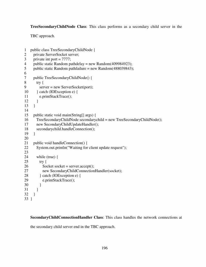
196
TreeSecondaryChildNode Class: This class performs as a secondary child server in the
TBC approach.
1 public class TreeSecondaryChildNode {
2 private ServerSocket server;
3 private int port = 7777;
4 public static Random pathdelay = new Random(409984923);
5 public static Random pathfailure = new Random(488039843);
6
7 public TreeSecondaryChildNode() {
8 try {
9 server = new ServerSocket(port);
10 } catch (IOException e) {
11 e.printStackTrace();
12 }
13 }
14
15 public static void main(String[] args) {
16 TreeSecondaryChildNode secondarychild = new TreeSecondaryChildNode();
17 new SecondaryChildUpdateHandler();
18 secondarychild.handleConnection();
19 }
20
21 public void handleConnection() {
22 System.out.println("Waiting for client update request");
23
24 while (true) {
25 try {
26 Socket socket = server.accept();
27 new SecondaryChildConnectionHandler(socket);
28 } catch (IOException e) {
29 e.printStackTrace();
30 }
31 }
32 }
33 }
SecondaryChildConnectionHandler Class: This class handles the network connections at
the secondary child server end in the TBC approach.

197
1 class SecondaryChildConnectionHandler implements Runnable {
2 private Socket socket;
3
4 public SecondaryChildConnectionHandler(Socket socket) {
5 this.socket = socket;
6 Thread t = new Thread(this);
7 t.start();
8 }
9
10 public void run() {
11 try {
12 ObjectInputStream ois = new ObjectInputStream(socket.getInputStream());
13 Transaction message = (Transaction) ois.readObject();
14 InetAddress sender = socket.getInetAddress();
15 ois.close();
16 socket.close();
17
18 InetAddress UB1 = InetAddress.getByAddress(new byte[]
{(byte)192,(byte)168,(byte)0,(byte)101});
19
20 int delay = 0;
21
22 if (sender.equals(UB1))
23 delay = getPathDelay(14);
24
25 try {
26 Thread.sleep( (long)delay );
27 } catch (InterruptedException ie) {
28 System.out.println(ie.getMessage());
29 }
30
31 if(message.type == 'A'){
32 if (sender.equals(UB1))
33 SecondaryChildUpdateHandler.MessageTrack[message.id].flag = false;
34 }else {
35 Transaction msg = new Transaction();
36 msg.id = message.id;
37 msg.type = 'A';
38 new SendMessage(sender.getAddress(), msg, 0.995);
39
40 if(sender.equals(UB1) && !SecondaryChildUpdateHandler.flag[message.id]){
41 SecondaryChildUpdateHandler.flag[message.id] = true;
42 SecondaryChildUpdateHandler.queue[message.id] = new
SecondaryChildTransactionManager(message.id, message);
43 }
44 }

198
45 } catch (IOException e) {
46 e.printStackTrace();
47 } catch (ClassNotFoundException e) {
48 e.printStackTrace();
49 }
50 }
51
52 int getPathDelay(int seed){
53 double rand = TreeSecondaryChildNode.pathdelay.nextDouble();
54 int delay = 0;
55
56 if(rand < .4)
57 delay = seed;
58 else if (rand <.8)
59 delay = seed + 1;
60 else if(rand < .9)
61 delay = (int) (seed + seed * .2);
62 else if(rand < .95)
63 delay = (int) (seed + 40 * .4);
64 else if(rand < .99)
65 delay = (int) (seed + 40 * .8);
66 else
67 delay = seed + 50 ;
68
69 return delay;
70 }
71 }
SecondaryChildTransactionHandler Class: This class handles the transaction requests at
the secondary child server end in the TBC approach.
1 class SecondaryChildTransactionHandler implements Runnable {
2 public static final int notr = 2000;
3 public static SecondaryChildTransactionManager []queue = new
SecondaryChildTransactionManager[notr];
4 public static boolean []flag = new boolean[notr];
5 public static SendMessage []MessageTrack = new SendMessage[notr];
6
7 public SecondaryChildTransactionHandler() {
8 Thread t = new Thread(this);
9 for(int i=0; i<notr;i++)
10 flag[i] = false;

199
11 t.start();
12 }
13
14 public void run() {
15 }
16 }
SecondaryChildTransactionManager Class: This class performs the jobs of a typical
transaction manager at the secondary child server end in the TBC approach.
1 class SecondaryChildTransactionManager implements Runnable {
2 public int id;
3 public Transaction T;
4 public int Transactiond;
5
6 public SecondaryChildTransactionManager (int id, Transaction T){
7 this.id = id;
8 this.T= T;
9 Transactiond = 0;
10 Thread t = new Thread(this);
11 t.start();
12 }
13
14 public void run(){
15 int count = 0;
16
17 while(count < T.no_op){
18 Operation O = T.operations.get(count++);
19
20 if(O.type == 'W'){
21 try {
22 Class.forName("com.mysql.jdbc.Driver");
23 Connection con = DriverManager.getConnection ("jdbc:mysql://localhost/tbc",
"root", "csgreen");
24 Statement stmt = con.createStatement();
25
26 String query = "insert into employee( lname, fname, ssn, bdate, address, sex, salary,
deptid ) values ( 'islam','ashfakul',";
27 query += T.id + ", null, '1514 paul w bryant','M', 21000,4);";
28 stmt.executeTransaction(query);
29 con.close();
30 } catch(ClassNotFoundException e) {

200
31 e.printStackTrace();
32 } catch(SQLException e) {
33 e.printStackTrace();
34 }
35 } else{
36 try {
37 Class.forName("com.mysql.jdbc.Driver");
38 Connection con = DriverManager.getConnection ("jdbc:mysql://localhost/tbc",
"root", "csgreen");
39 Statement stmt = con.createStatement();
40 String query = " select max(rowid) from employee;";
41 ResultSet rs = stmt.executeQuery(query);
42
43 while (rs.next()) {
44 }
45 con.close();
46 } catch(ClassNotFoundException e) {
47 e.printStackTrace();
48 }catch(SQLException e) {
49 e.printStackTrace();
50 }
51 }
52 }
53
54 Transaction msg = new Transaction();
55 msg.id = T.id;
56 msg.type = 'P';
57 SecondaryChildTransactionHandler.MessageTrack[T.id] = new SendMessage( new
byte[] {(byte)192,(byte)168,(byte)0,(byte)101}, msg, 0.995);
58
59 System.out.println("Transaction " + id + " is executed ");
60 }
61 }