Database Concepts
19
What is DBMS? Database Management System is a set of computer programs that controls the creation, maintenance, and the use of a database. What is a Schema? A description of data in terms of data model is called a schema. In the relational model, the schema for a relation specifies its name, the name of each field (or attribute or column), and the type of each filed. Example for student information in a university database may be stored in a relation with the following schema: Student ( sid: string, name: string, login: string, age: integer, gpa: real) What is DDL? A data definition language (DDL) is used to define the external and conceptual schemas. What is a Database? A database is a collection of data. Data in the database: is integrated Can be shared Can be concurrently accessed The database systems are designed to: Define structures for the storage of data Provide mechanisms for the manipulation of data Ensure the safety of the data stored, despite system crashes or attempts at unauthorized access Share data among the different users In short, database systems are designed to manage large volumes of data. The first general-purpose DBMS, designed by Charles Bachman at General Electric in the early 1960s, was called the Integrated Data store. In the late 1960s, IBM developed the information Management System (IMS) DBMS. File System Interface versus DBMS Interface In the traditional file approach, data is stored in flat files which are maintained by the file system, under the operating systems control. The end users use the application
-
Upload
upendra-reddy -
Category
Education
-
view
346 -
download
0
Transcript of Database Concepts

What is DBMS?
Database Management System is a set of computer programs that controls the creation,
maintenance, and the use of a database.
What is a Schema?
A description of data in terms of data model is called a schema. In the relational model,
the schema for a relation specifies its name, the name of each field (or attribute or
column), and the type of each filed. Example for student information in a university
database may be stored in a relation with the following schema:
Student ( sid: string, name: string, login: string, age: integer, gpa: real)
What is DDL?
A data definition language (DDL) is used to define the external and conceptual schemas.
What is a Database?
A database is a collection of data.
Data in the database:
is integrated
Can be shared
Can be concurrently accessed
The database systems are designed to:
Define structures for the storage of data
Provide mechanisms for the manipulation of data
Ensure the safety of the data stored, despite system crashes or attempts at
unauthorized access
Share data among the different users
In short, database systems are designed to manage large volumes of data.
The first general-purpose DBMS, designed by Charles Bachman at General
Electric in the early 1960s, was called the Integrated Data store. In the late 1960s, IBM
developed the information Management System (IMS) DBMS.
File System Interface versus DBMS Interface
In the traditional file approach, data is stored in flat files which are maintained by
the file system, under the operating systems control. The end users use the application

programs to perform specific tasks. All application programs go through the file system
to access the data stored in these flat files.
In the DBMS approach, all requests to use the data stored in the database are
handled by the DBMS. The end user can use either the application programs or the
standard SQL to access the data.
Flat Files: A flat file is a file containing records that has no structured interrelationship.
Files used in programming fundamentals projects were essentially flat files.
SQL: (Structured Query Language). A language used by relational databases to query,
update and manage data.
The data in the database can be shared. Sharing means individual pieces of data in the
database can be shared among different users.
Points to Remember:
Disadvantages of the traditional file approach:
Data Security – Data easily accessible by all and therefore not secure
Data Redundancy – Same data is duplicated in two or more files which may lead
to update anomalies
Data Isolation – All the related data is not available in one file. Thus writing a
new application program is difficult
Program / Data Dependence – Application programs are data dependent. It is
impossible to change the physical representation (how the data is physically
represented in storage) or access technique (how it is physically accessed) without
affecting the application.
Lack of Flexibility – Only pre-determined request for information can be met. It
is not flexible to satisfy unanticipated queries.
Concurrent Access Anomalies – Same piece of data is allowed to be updated
simultaneously which leads to inconsistencies.
DBMS ensures the following
Application programs and queries are data-independent. They do not depend on
any one particular physical representation of data in secondary storage of access
technique
Allows for sharing of data among different users. Users are also able to access the
database concurrently without facing the issues of inconsistent data.
Controls redundancy and inconsistency

Provides secure access to that database
Enforces integrity constraints (also known as business rules) by preventing the
entity of invalid information into the database.
Enables backup and recovery from system crashes.
Queries: - A query is essentially a request that a user makes on the database.
Integrity Constraints: A set of rules to ensure the correctness and accuracy of data.
Types of Databases
There are two generic database architectures: centralized and distributed.
Centralized: All data is located at a single site. Allows for greater control over accessing
and updating data
Distributed: The database is stored on several computers from personal computers up to
mainframe systems. Computers in a distributed system communicate with one another
through various communication media such as high speed networks or telephone lines.
Distributed databases are geographically separated and managed.
DBMS Architecture Most commercial databases are based on the three-level architecture model called
the ANSI/SPARC (American National Standards Institute/Standard Planning and
Requirements Committee) model.

Database architecture is in there levels. Those are
1. External/View Level
2. Conceptual Level
3. Internal Level
The overall design of the database is called database schema. Schemas are not changed
frequently. In general, database systems support one internal schema, one conceptual
schema and several external schemas.
External / View Level: Many users of the database system are not concerned with all the
information in the database. Instead, they need to access only a part of the database. The
external level of abstraction simplifies the end users interaction with the system. The
system may provide many views for the same database.
Conceptual / Logical Level: The conceptual level describes what data are stored in the
database, and what relationships exist among those data. This level is used by the
Database Administrator, who in turn decides what information must be kept in the
database.

Internal / Physical level: The internal level is the lowest level of abstraction and
describes the data storage and access methods. Database Administrator may be aware of
certain details of the physical organization of the data.
Guidelines to select a primary key:
Give preference to numeric columns(s). The search algorithm performs better
when the primary key is numeric
Give preference to a single attribute. The search algorithm gives better output with
a single attribute primary key than with a composite attribute primary key
Give preference to the minimal composite key. A composite key is a collection of
two or more attributes.
Primary keys are chosen according to business convenience.
DBMS Users End Users: Works at the external level and generally makes updates to the database or
executes queries on the database.
Application Programmer: Writes application programs.
Database Administrator: Defines the conceptual, internal and external schema, control
access privileges to/from users and ensures the consistency of the database.
Different types Keys Candidate/Primary Key: - A Primary key is a set of one or more attributes that can
uniquely identify a row in a given table.
Foreign Key: - A foreign key is a set of attributes the values of which are required to
match the values of a candidate key in the same or another table. The foreign key
attributes can have duplicate or null values.
Self Referencing: - A table might include a foreign key, the values of which are required
to match the value of a candidate key in the same table. This is known as self referencing.

Non –Key Attributes: The attributes other than the primary key attributes in a
table/relation are called non-key attributes.
Data Models A data model is a conceptual toll to describe data, data relationships, data schematics and
consistency constraints. Two of the widely used data models are
1) Object Based Logical Model
a) E-R Model
2) Record Based Logical Model
a) Hierarchical Data Model
b) Network Data Model
c) Relational Data Model
d) Structural Terminology
RDBMS Relational Database Management System is a type of DBMS that stores data in the
form of related tables.
Databases are widely used in real life applications such as:
1) Airlines: for reservations and schedule information.
2) Banking: for customer information, accounts, loans and banking transactions
3) Universities: For student information, course registrations and grades.

4) Telecommunications: For keeping records of calls made, generating monthly bills,
maintaining balances on prepaid calling cards and storing information about the
communication networks.
5) Sales: For customer, product and purchase information in any industry.
Entity Relationship model (E-R Model) Entity relationship Diagram (ERD) was first defined in 1976 by peter chen. Since
then Charles Bachman and James Martin have added some small refinements to the basic
ERD principles.
Entity: Entity is a common word anything real or abstract, about which we want to store
data. Entity types fall into five categories: roles, events, locations, tangible things or
concepts.
Attribute: An attribute is a characteristic property of an entity. An entity could have
multiple attributes.
Example: For an entity car, the attributes would be the color, model number, number of
doors, right or left hand drive etc.
Relationship: Relationship is a natural association that exists between one or more
entities.
Cardinality of a Relationship: Cardinality of relationship defines the type of
relationship between two participating entities.
Example: One employee can take many books from library. One book can be taken by
only one employee. Cardinality of relationship between employee and book is “one to
many”.
There are four types of cardinality relationship.
i) One to One Relationship
ii) One to Many Relationship
iii) Many to One Relationship
Example: Many employees can work for only one department but one
department can have many employees.
iv) Many to Many Relationship
Example: One Student is enrolled for many courses and one course is enrolled
by many students.

E-R Diagram Notations Entity: an Entity is an object or concept about which business user wants to store
information
Weak entity: A weak entity is dependent on another entity to exist. Example bank
branch depends upon bank name for its existence. Without bank name it is impossible to
identify bank uniquely.
Attributes: Attributes are the properties or characteristics of an entity.
Key attribute: A key attribute is the unique (primary key), distinguishing characteristic
of the entity.
Multi valued attribute: A multi valued attribute can have more than one value. For
example, an employee entity can have multiple skill values.
Derived attribute: A derived attribute is based on another attribute. For example, an
employee’s monthly salary is based on the employee’s basic salary and house rent
allowance.
Relationships: Relationships illustrate how two entities share information in the database
structure.
A model is an abstract from of any system or process that hides the unnecessary
details, while highlighting those details important to the application. This will help the
business users to visualize the application before it is developed and suggest changes, if it
is not as per their requirement.
Modeling the databases using E-R diagrams is called as E-R Modeling. This
technique is also called as Top-Down approach, because one need not identify all the
attributes to model the system using this technique.
Steps in E-R Modeling
Usually the following six steps are followed to generate E-R Models.
a. Identify the entities: Look for general nouns in requirements specification document
which are of business interest to business users.
b. Find relationships: Identify the natural relationship and their cardinalities between
the entities.
c. Identify the key attributes for every entity: Identify the attribute or set of attributes
which can identify instance of entity uniquely
d. Identify other relevant attributes: Identify other attributes which are interest to
business users and want to store the information in database.
e. Complete E-R diagram: Draw complete E-R diagram with all attributes including
primary key.
f. Review your results with your business users: Look at the list of attributes
associated with each entity to see if anything has been omitted.
Advantages of E-R Modeling
1. Easy to understand. Represented in business users language. Can be understood by
non-technical specialist.
2. Intuitive and helps in physical database creation.
3. Can be generalized and specialized based on needs.
4. Can help in database design
5. Gives a higher level abstraction of the system.
What is normalization? Normalization is the process of efficiently organizing data in a database. There are
two goals of the normalization process:
1. Eliminating redundant data (for example, storing the same data in more than one
table)
2. Ensuring data dependencies make sense (only storing related data in a table). OR
Organize data into an efficient and logical structure.
Both of these are worthy goals as they reduce the amount of space a database consumes
and ensure that data is logically stored.
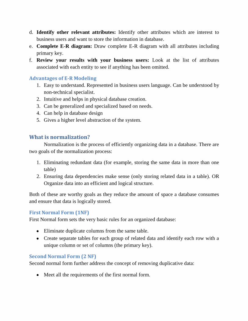
First Normal Form (1NF)
First Normal form sets the very basic rules for an organized database:
Eliminate duplicate columns from the same table.
Create separate tables for each group of related data and identify each row with a
unique column or set of columns (the primary key).
Second Normal Form (2 NF)
Second normal form further address the concept of removing duplicative data:
Meet all the requirements of the first normal form.

Remove subsets of data that apply to multiple rows of a table and place them in
separate tables.
Create relationships between these new tables and their predecessors through the
use of foreign keys.
Third Normal Form (3 NF)
Third normal form goes one large step further:
Meet all the requirements of the second normal form.
Remove columns that are not dependent upon the primary key.
Boyce Codd Normal Form (BCNF)
A relation is said to be in Boyce Codd Normal Form if and only if all the determinants
are candidate keys. BCNF relation is a strong 3NF, but not every 3NF relation is BCNF.
Let us understand this concept by using Result table structure.
In the above table we have two candidate keys namely Student# Course# and course#
Emailid. Course# is overlapping among those candidate keys. Hence these candidate
keys are called as “overlapping candidate keys”.
The non-key attribute, Marks is non-transitively and fully functionally dependant on key
attributes. Hence this is in 3NF. But this is not in BCNF because there are four
determinants in this relation namely:

Student# (Student# decides EMailid)
Emailid (Emailid decides Student#)
Student# Course# (decides rest of the attributes in Result table)
Course# Emailid (decides rest of the attributes in Result table)
All above determinants are not candidate keys. Emailid decides Student# but
Emailid on its own is not a candidate key. Similarly Student# decides Emailid of a
student but Student# alone is not a candidate key. Only combination of Student# Course#
and Course# Emailid are candidate keys.
To make this table BCNF, we need to split this table into the following structure:
Fourth Normal Form (4 NF)
Finally, fourth normal form has one additional requirement:
Meet all the requirement of the third normal form.
A relation is in 4NF if it has no multi-valued dependencies.
Explanation with Example
Let's say we want to create a table of user information, and we want to store each
users' Name, Company, Company Address, and some personal bookmarks, or urls. You
might start by defining a table structure like this:

Zero Form
users Name company company_address url1 url2 Joe ABC 1 Work Lane abc.com xyz.com Jill XYZ 1 Job Street abc.com xyz.com
We would say this table is in Zero Form because none of our rules of normalization
have been applied yet. Notice the url1 and url2 fields -- what do we do when our
application needs to ask for a third url? Do you want to keep adding columns to your
table and hard-coding that form input field into your HTML code? Obviously not, you
would want to create a functional system that could grow with new development
requirements. Let's look at the rules for the First Normal Form, and then apply them to
this table.
First Normal Form
Eliminate repeating groups in individual tables.
Create a separate table for each set of related data.
Identify each set of related data with a primary key.
Notice how we're breaking that first rule by repeating the url1 and url2 fields? And
what about Rule Three, primary keys? Rule Three basically means we want to put some
form of unique, auto-incrementing integer value into every one of our records. Otherwise,
what would happen if we had two users named Joe and we wanted to tell them apart?
When we apply the rules of the First Normal Form we come up with the following table:
users userId name company company_address url
1 Joe ABC 1 Work Lane abc.com 1 Joe ABC 1 Work Lane xyz.com 2 Jill XYZ 1 Job Street abc.com 2 Jill XYZ 1 Job Street xyz.com
[
Now our table is said to be in the First Normal Form. We've solved the problem of
url field limitation, but look at the headache we've now caused ourselves. Every time we
input a new record into the users table, we've got to duplicate all that company and user
name data. Not only will our database grow much larger than we'd ever want it to, but we
could easily begin corrupting our data by misspelling some of that redundant information.
Let's apply the rules of Second Normal Form:
Second Normal Form
Create separate tables for sets of values that apply to multiple records.

Relate these tables with a foreign key.
We break the url values into a separate table so we can add more in the future without
having to duplicate data. We'll also want to use our primary key value to relate these
fields:
users userId name company company_address
1 Joe ABC 1 Work Lane 2 Jill XYZ 1 Job Street
Ok, we've created separate tables and the primary key in the users table, userId, is
now related to the foreign key in the urls table, relUserId. We're in much better shape.
But what happens when we want to add another employee of company ABC? Or 200
employees? Now we've got company names and addresses duplicating themselves all
over the place, a situation just rife for introducing errors into our data. So we'll want to
look at applying the Third Normal Form:
Third Normal Form
Eliminate fields that do not depend on the key.
Our Company Name and Address have nothing to do with the User Id, so they should
have their own Company Id:
users userId name relCompId
1 Joe 1 2 Jill 2
urls urlId relUserId url
1 1 abc.com 2 1 xyz.com 3 2 abc.com 4 2 xyz.com
urls urlId relUserId url
1 1 abc.com 2 1 xyz.com 3 2 abc.com 4 2 xyz.com

Now we've got the primary key compId in the companies table related to the foreign
key in the users table called relCompId, and we can add 200 users while still only
inserting the name "ABC" once. Our users and urls tables can grow as large as they want
without unnecessary duplication or corruption of data. Most developers will say the Third
Normal Form is far enough, and our data schema could easily handle the load of an entire
enterprise, and in most cases they would be correct.
But look at our url fields - do you notice the duplication of data? This is perfectly
acceptable if we are not pre-defining these fields. If the HTML input page which our
users are filling out to input this data allows a free-form text input there's nothing we can
do about this, and it's just a coincidence that Joe and Jill both input the same bookmarks.
But what if it's a drop-down menu which we know only allows those two urls, or maybe
20 or even more. We can take our database schema to the next level, the Fourth Form,
one which many developers overlook because it depends on a very specific type of
relationship, the many-to-many relationship, which we have not yet encountered in our
application.
Data Relationships
Before we define the Fourth Normal Form, let's look at the three basic data relationships:
one-to-one, one-to-many, and many-to-many. Look at the users table in the First
Normal Form example above. For a moment let's imagine we put the url fields in a
separate table, and every time we input one record into the users table we would input
one row into the urls table. We would then have a one-to-one relationship: each row in
the users table would have exactly one corresponding row in the urls table. For the
purposes of our application this would neither be useful nor normalized.
Now look at the tables in the Second Normal Form example. Our tables allow one user to
have many urls associated with his user record. This is a one-to-many relationship, the
most common type, and until we reached the dilemma presented in the Third Normal
Form, the only kind we needed.
companies compId company company_address
1 ABC 1 Work Lane 2 XYZ 1 Job Street

The many-to-many relationship, however, is slightly more complex. Notice in our Third
Normal Form example we have one user related to many urls. As mentioned, we want to
change that structure to allow many users to be related to many urls, and thus we want a
many-to-many relationship. Let's take a look at what that would do to our table structure
before we discuss it:
users
userId name relCompId
1 Joe 1
2 Jill 2
companies
compId company company_address
1 ABC 1 Work Lane
2 XYZ 1 Job Street
urls
urlId url
1 abc.com
2 xyz.com
url_relations
relationId relatedUrlId relatedUserId
1 1 1
2 1 2
3 2 1
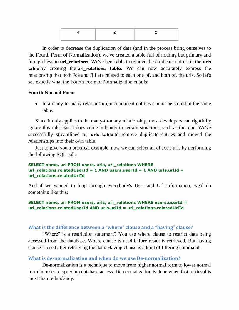
4 2 2
In order to decrease the duplication of data (and in the process bring ourselves to
the Fourth Form of Normalization), we've created a table full of nothing but primary and
foreign keys in url_relations. We've been able to remove the duplicate entries in the urls
table by creating the url_relations table. We can now accurately express the
relationship that both Joe and Jill are related to each one of, and both of, the urls. So let's
see exactly what the Fourth Form of Normalization entails:
Fourth Normal Form
In a many-to-many relationship, independent entities cannot be stored in the same
table.
Since it only applies to the many-to-many relationship, most developers can rightfully
ignore this rule. But it does come in handy in certain situations, such as this one. We've
successfully streamlined our urls table to remove duplicate entries and moved the
relationships into their own table.
Just to give you a practical example, now we can select all of Joe's urls by performing
the following SQL call:
SELECT name, url FROM users, urls, url_relations WHERE
url_relations.relatedUserId = 1 AND users.userId = 1 AND urls.urlId =
url_relations.relatedUrlId
And if we wanted to loop through everybody's User and Url information, we'd do
something like this:
SELECT name, url FROM users, urls, url_relations WHERE users.userId =
url_relations.relatedUserId AND urls.urlId = url_relations.relatedUrlId
What is the difference between a “where” clause and a “having” clause?
“Where” is a restriction statement? You use where clause to restrict data being
accessed from the database. Where clause is used before result is retrieved. But having
clause is used after retrieving the data. Having clause is a kind of filtering command.
What is de-normalization and when do we use De-normalization?
De-normalization is a technique to move from higher normal form to lower normal
form in order to speed up database access. De-normalization is done when fast retrieval is
must than redundancy.

SQL Statements:
Statement Syntax
AND / OR SELECT column_name(s) FROM table_name WHERE condition AND|OR condition
ALTER TABLE ALTER TABLE table_name ADD column_name datatype
or
ALTER TABLE table_name DROP COLUMN column_name
AS (alias) SELECT column_name AS column_alias FROM table_name
or
SELECT column_name FROM table_name AS table_alias
BETWEEN SELECT column_name(s) FROM table_name WHERE column_name BETWEEN value1 AND value2
CREATE DATABASE CREATE DATABASE database_name
CREATE TABLE CREATE TABLE table_name ( column_name1 data_type, column_name2 data_type, column_name2 data_type, ... )
CREATE INDEX CREATE INDEX index_name ON table_name (column_name)
or
CREATE UNIQUE INDEX index_name ON table_name (column_name)
CREATE VIEW CREATE VIEW view_name AS SELECT column_name(s) FROM table_name WHERE condition
DELETE DELETE FROM table_name WHERE some_column=some_value

or
DELETE FROM table_name (Note: Deletes the entire table!!)
DELETE * FROM table_name (Note: Deletes the entire table!!)
DROP DATABASE DROP DATABASE database_name
DROP INDEX DROP INDEX table_name.index_name (SQL Server) DROP INDEX index_name ON table_name (MS Access) DROP INDEX index_name (DB2/Oracle) ALTER TABLE table_name DROP INDEX index_name (MySQL)
DROP TABLE DROP TABLE table_name
GROUP BY SELECT column_name, aggregate_function(column_name) FROM table_name WHERE column_name operator value GROUP BY column_name
HAVING SELECT column_name, aggregate_function(column_name) FROM table_name WHERE column_name operator value GROUP BY column_name HAVING aggregate_function(column_name) operator value
IN SELECT column_name(s) FROM table_name WHERE column_name IN (value1,value2,..)
INSERT INTO INSERT INTO table_name VALUES (value1, value2, value3,....)
or
INSERT INTO table_name (column1, column2, column3,...) VALUES (value1, value2, value3,....)
INNER JOIN SELECT column_name(s) FROM table_name1 INNER JOIN table_name2 ON table_name1.column_name=table_name2.column_name
LEFT JOIN SELECT column_name(s) FROM table_name1 LEFT JOIN table_name2 ON table_name1.column_name=table_name2.column_name
RIGHT JOIN SELECT column_name(s) FROM table_name1 RIGHT JOIN table_name2

ON table_name1.column_name=table_name2.column_name
FULL JOIN SELECT column_name(s) FROM table_name1 FULL JOIN table_name2 ON table_name1.column_name=table_name2.column_name
LIKE SELECT column_name(s) FROM table_name WHERE column_name LIKE pattern
ORDER BY SELECT column_name(s) FROM table_name ORDER BY column_name [ASC|DESC]
SELECT SELECT column_name(s) FROM table_name
SELECT * SELECT * FROM table_name
SELECT DISTINCT SELECT DISTINCT column_name(s) FROM table_name
SELECT INTO SELECT * INTO new_table_name [IN externaldatabase] FROM old_table_name
or
SELECT column_name(s) INTO new_table_name [IN externaldatabase] FROM old_table_name
SELECT TOP SELECT TOP number|percent column_name(s) FROM table_name
TRUNCATE TABLE TRUNCATE TABLE table_name
UNION SELECT column_name(s) FROM table_name1 UNION SELECT column_name(s) FROM table_name2
UNION ALL SELECT column_name(s) FROM table_name1 UNION ALL SELECT column_name(s) FROM table_name2
UPDATE UPDATE table_name SET column1=value, column2=value,... WHERE some_column=some_value
WHERE SELECT column_name(s) FROM table_name WHERE column_name operator value