Data Transmission Systems PowerTranS Ib (rS 485, DH +)€¦ · Data Transmission Systems ......
20
Data Transmission Systems POWERTRANS ® Ib (RS 485, DH +) Program 0512
-
Upload
phunghuong -
Category
Documents
-
view
221 -
download
1
Transcript of Data Transmission Systems PowerTranS Ib (rS 485, DH +)€¦ · Data Transmission Systems ......

Data Transmission Systems PowerTranS® Ib (rS 485, DH +)Program 0512


3
Contents
FundamentalsRange of Application: Data Transmission System for Mobile Consumers . . . . . . . . . . . . . . . . . . . . . . . . . . . . . . . . . . . . . . . . . . . . . . . . . . . . . . . . . . . . . . . . . . . . . . . . . . . . . 4Operational Principle . . . . . . . . . . . . . . . . . . . . . . . . . . . . . . . . . . . . . . . . . . . . . . . . . . . . . . . . . . . . . . . . . . . . . . . . . . . . . . . . . . . . . . . . . . . . . . . . . . . . . . . . . . . . . . . . . . 4Typical Data Interfaces of the Powertrans® Ib Unit . . . . . . . . . . . . . . . . . . . . . . . . . . . . . . . . . . . . . . . . . . . . . . . . . . . . . . . . . . . . . . . . . . . . . . . . . . . . . . . . . . . . . . . . . . . . . 5Terminators for Conductor Rails and Cables . . . . . . . . . . . . . . . . . . . . . . . . . . . . . . . . . . . . . . . . . . . . . . . . . . . . . . . . . . . . . . . . . . . . . . . . . . . . . . . . . . . . . . . . . . . . . . . . . 5Bus Terminators of the Bus Cable . . . . . . . . . . . . . . . . . . . . . . . . . . . . . . . . . . . . . . . . . . . . . . . . . . . . . . . . . . . . . . . . . . . . . . . . . . . . . . . . . . . . . . . . . . . . . . . . . . . . . . . . . 5
Types of operationHalf Duplex (2-poles), e .g . Profibus . . . . . . . . . . . . . . . . . . . . . . . . . . . . . . . . . . . . . . . . . . . . . . . . . . . . . . . . . . . . . . . . . . . . . . . . . . . . . . . . . . . . . . . . . . . . . . . . . . . . . . . . 6Full Duplex (4-poles), e .g . RS 422 . . . . . . . . . . . . . . . . . . . . . . . . . . . . . . . . . . . . . . . . . . . . . . . . . . . . . . . . . . . . . . . . . . . . . . . . . . . . . . . . . . . . . . . . . . . . . . . . . . . . . . . . . 6
DefinitionGeneral . . . . . . . . . . . . . . . . . . . . . . . . . . . . . . . . . . . . . . . . . . . . . . . . . . . . . . . . . . . . . . . . . . . . . . . . . . . . . . . . . . . . . . . . . . . . . . . . . . . . . . . . . . . . . . . . . . . . . . . . . . . . 7Bus Structure: Connecting Structures of Information Processing Systems . . . . . . . . . . . . . . . . . . . . . . . . . . . . . . . . . . . . . . . . . . . . . . . . . . . . . . . . . . . . . . . . . . . . . . . . . . . 7
System ComponentsPowertrans®-Set 230 V / RS 485 . . . . . . . . . . . . . . . . . . . . . . . . . . . . . . . . . . . . . . . . . . . . . . . . . . . . . . . . . . . . . . . . . . . . . . . . . . . . . . . . . . . . . . . . . . . . . . . . . . . . . . . . . 8 Powertrans® Ib Basic Unit for Interfaces RS 485/422/232, DH + . . . . . . . . . . . . . . . . . . . . . . . . . . . . . . . . . . . . . . . . . . . . . . . . . . . . . . . . . . . . . . . . . . . . . . . . . . . . . . . . . . 8Powertrans® Ib Interface for Switchboard Assembly on Support Rail TS 35 . . . . . . . . . . . . . . . . . . . . . . . . . . . . . . . . . . . . . . . . . . . . . . . . . . . . . . . . . . . . . . . . . . . . . . . . . . . 8Powertrans® Ib Pair of Optical Fibers . . . . . . . . . . . . . . . . . . . . . . . . . . . . . . . . . . . . . . . . . . . . . . . . . . . . . . . . . . . . . . . . . . . . . . . . . . . . . . . . . . . . . . . . . . . . . . . . . . . . . . 9Terminator/Conductor Rail – in a Case . . . . . . . . . . . . . . . . . . . . . . . . . . . . . . . . . . . . . . . . . . . . . . . . . . . . . . . . . . . . . . . . . . . . . . . . . . . . . . . . . . . . . . . . . . . . . . . . . . . . . 9Connectors/Conductor Rail – without Case for Switchboard Installation . . . . . . . . . . . . . . . . . . . . . . . . . . . . . . . . . . . . . . . . . . . . . . . . . . . . . . . . . . . . . . . . . . . . . . . . . . . . . 9Terminator/Conductor Rail – without Case for Switchboard Installation on Support Rail TS 35 . . . . . . . . . . . . . . . . . . . . . . . . . . . . . . . . . . . . . . . . . . . . . . . . . . . . . . . . . . . . . 9Technical Data . . . . . . . . . . . . . . . . . . . . . . . . . . . . . . . . . . . . . . . . . . . . . . . . . . . . . . . . . . . . . . . . . . . . . . . . . . . . . . . . . . . . . . . . . . . . . . . . . . . . . . . . . . . . . . . . . . . . . . 10
Project, assembly and Starting operationMaximum Lengths for Conductor Rails . . . . . . . . . . . . . . . . . . . . . . . . . . . . . . . . . . . . . . . . . . . . . . . . . . . . . . . . . . . . . . . . . . . . . . . . . . . . . . . . . . . . . . . . . . . . . . . . . . . . 11Recommended Configuration of the Conductor Rail . . . . . . . . . . . . . . . . . . . . . . . . . . . . . . . . . . . . . . . . . . . . . . . . . . . . . . . . . . . . . . . . . . . . . . . . . . . . . . . . . . . . . . . . . . . 11Bus Terminators . . . . . . . . . . . . . . . . . . . . . . . . . . . . . . . . . . . . . . . . . . . . . . . . . . . . . . . . . . . . . . . . . . . . . . . . . . . . . . . . . . . . . . . . . . . . . . . . . . . . . . . . . . . . . . . . . . . . 11System Examples 1 . . . . . . . . . . . . . . . . . . . . . . . . . . . . . . . . . . . . . . . . . . . . . . . . . . . . . . . . . . . . . . . . . . . . . . . . . . . . . . . . . . . . . . . . . . . . . . . . . . . . . . . . . . . . . . . . . . 11System Examples 2 . . . . . . . . . . . . . . . . . . . . . . . . . . . . . . . . . . . . . . . . . . . . . . . . . . . . . . . . . . . . . . . . . . . . . . . . . . . . . . . . . . . . . . . . . . . . . . . . . . . . . . . . . . . . . . . . . . 12Electric Connection (also see standard connection diagram) . . . . . . . . . . . . . . . . . . . . . . . . . . . . . . . . . . . . . . . . . . . . . . . . . . . . . . . . . . . . . . . . . . . . . . . . . . . . . . . . . . . . 12Shielding . . . . . . . . . . . . . . . . . . . . . . . . . . . . . . . . . . . . . . . . . . . . . . . . . . . . . . . . . . . . . . . . . . . . . . . . . . . . . . . . . . . . . . . . . . . . . . . . . . . . . . . . . . . . . . . . . . . . . . . . . . 12Standard Connection Diagram: Application Example for Half Duplex (2 poles) . . . . . . . . . . . . . . . . . . . . . . . . . . . . . . . . . . . . . . . . . . . . . . . . . . . . . . . . . . . . . . . . . . . . . . . . 13Indicators / (LED) . . . . . . . . . . . . . . . . . . . . . . . . . . . . . . . . . . . . . . . . . . . . . . . . . . . . . . . . . . . . . . . . . . . . . . . . . . . . . . . . . . . . . . . . . . . . . . . . . . . . . . . . . . . . . . . . . . . . 14Indicator / LED in Case of Disturbance . . . . . . . . . . . . . . . . . . . . . . . . . . . . . . . . . . . . . . . . . . . . . . . . . . . . . . . . . . . . . . . . . . . . . . . . . . . . . . . . . . . . . . . . . . . . . . . . . . . . 14 Cause for Disturbance . . . . . . . . . . . . . . . . . . . . . . . . . . . . . . . . . . . . . . . . . . . . . . . . . . . . . . . . . . . . . . . . . . . . . . . . . . . . . . . . . . . . . . . . . . . . . . . . . . . . . . . . . . . . . . . . 15Elimination of Disturbance . . . . . . . . . . . . . . . . . . . . . . . . . . . . . . . . . . . . . . . . . . . . . . . . . . . . . . . . . . . . . . . . . . . . . . . . . . . . . . . . . . . . . . . . . . . . . . . . . . . . . . . . . . . . . 15Special Requirements for DH + Interface Module . . . . . . . . . . . . . . . . . . . . . . . . . . . . . . . . . . . . . . . . . . . . . . . . . . . . . . . . . . . . . . . . . . . . . . . . . . . . . . . . . . . . . . . . . . . . 15Volume of Delivery . . . . . . . . . . . . . . . . . . . . . . . . . . . . . . . . . . . . . . . . . . . . . . . . . . . . . . . . . . . . . . . . . . . . . . . . . . . . . . . . . . . . . . . . . . . . . . . . . . . . . . . . . . . . . . . . . . . 16Personal Security . . . . . . . . . . . . . . . . . . . . . . . . . . . . . . . . . . . . . . . . . . . . . . . . . . . . . . . . . . . . . . . . . . . . . . . . . . . . . . . . . . . . . . . . . . . . . . . . . . . . . . . . . . . . . . . . . . . . 16Equipment Security . . . . . . . . . . . . . . . . . . . . . . . . . . . . . . . . . . . . . . . . . . . . . . . . . . . . . . . . . . . . . . . . . . . . . . . . . . . . . . . . . . . . . . . . . . . . . . . . . . . . . . . . . . . . . . . . . . 16Transport Damage . . . . . . . . . . . . . . . . . . . . . . . . . . . . . . . . . . . . . . . . . . . . . . . . . . . . . . . . . . . . . . . . . . . . . . . . . . . . . . . . . . . . . . . . . . . . . . . . . . . . . . . . . . . . . . . . . . . 16Mounting of the Basic Unit and Interface . . . . . . . . . . . . . . . . . . . . . . . . . . . . . . . . . . . . . . . . . . . . . . . . . . . . . . . . . . . . . . . . . . . . . . . . . . . . . . . . . . . . . . . . . . . . . . . . . . . 16Questionnaire . . . . . . . . . . . . . . . . . . . . . . . . . . . . . . . . . . . . . . . . . . . . . . . . . . . . . . . . . . . . . . . . . . . . . . . . . . . . . . . . . . . . . . . . . . . . . . . . . . . . . . . . . . . . . . . . . . . . . . 17
Program overviewConductor Rails . . . . . . . . . . . . . . . . . . . . . . . . . . . . . . . . . . . . . . . . . . . . . . . . . . . . . . . . . . . . . . . . . . . . . . . . . . . . . . . . . . . . . . . . . . . . . . . . . . . . . . . . . . . . . . . . . . . . . 18General Hints . . . . . . . . . . . . . . . . . . . . . . . . . . . . . . . . . . . . . . . . . . . . . . . . . . . . . . . . . . . . . . . . . . . . . . . . . . . . . . . . . . . . . . . . . . . . . . . . . . . . . . . . . . . . . . . . . . . . . . . 18

4
5
4
3
2
1
9
8
7
6
Fundamentals
range of application: Data Transmission System for Mobile Consumers
Powertrans® Ib systems are used forConductor rails in interiors, e.g. in• High storage warehouses• Crane systems• Hoists• Transport systems• Hand-operated overhead conveyor systems• Handling systems
Slip ring bodies in• Rotary cranes, excavators• Water treatment works• Amusement rides• Manipulators• Packing machines
Cables for• Cable reels• Control cables• Crane systems
Voltages or currents of the data signals on Bus systems are often too low to achieve a reliable and trouble-free data transmission . Sliding contact surfaces tend to form oxide layers and may cause short-time interruptions in contaminated environments . To achieve low and constant contact resistance between contact surfaces and current collector, Powertrans® Ib increases the power level of the data signals . In connection with double current collectors this allows a safe and reliable data transmission .The increase of the signal level also produces a strong insensibility to inductive and capacitive interference from neighboring conductors to the Bus system (e .g . on cable reels, festoons or longer supplies) .The transparent data transmission prevents relevant retardation times or long-time transmission records .Reference systems with system connection to various automation computers with standard interfaces RS 485, RS 422, RS 232 and DH + are in operation .
operational Principle
1 . Stock control computers2 . Automation computers (PLC)3 . Powertrans® Ib basic unit4 . Powertrans® Ib interface5 . Powertrans® Ib pair of optical fibers6 . Conductix-Wampfler conductor rail7 . Conductix-Wampfler terminator / conductor rail8 . Conductix-Wampfler double current collector9 . Decentralized peripheral unit
On Powertrans® Ib the interface is connected to the compact basic unit by optical fibers . If the existing interface is changed, this presents the advantage that only the interface will have to be replaced . Moreover the basic unit can be removed from the interface, which is often placed near a PLC .The PLC signals are electrically disconnected from sending and receiving by means of Opto-coupling components .Each unit (basic unit, interface and pair of optical fibers) includes a sender and a receiver .The sender increases the signal level of the interface signal from unit A to ± 70 V (potential-free) for connection to the corresponding transmission medium . The receiver of unit B reduces the signal level back to the appropriate interface level .The units support different serial data forms, such as RS 485, RS 422, RS 232 oder DH + .All entries and/or exits are short circuit resistant .For max . cable lengths use two-wire twisted and shielded cables according to the specifications of the PLC manufacturer .A 9-pole Sub-D or DH+-clamp provides for the coupling of different interface signals .In general the transmission rate should be as low as possible, depending on the application . The specific determination of response times and repeating times during programming of the Bus system by the operator additionally supports a safe trans-mission of data . PLC adjustments for unshielded cables have to be set (RETRY-Level > 0) .
2
5
6
7 78
5
9
1
3
4
3
4
Interface ConnectionsPIn Sub-D
RS 485 RS 422 RS 232 DH +
1 - - - Data Line 1
2 - Rxd-P - SGND
3 Rxd / Txd-P Txd-P Txd Data Line 2
4 - + 12 V -
5 SGND SGND SGND -
6 + U + U - -
7 - Rxd-N - -
8 Rxd / Txd-N Txd-N Rxd -
9 - - - -
Sub-D DH +
1 DH+ Data Line 1
2 Shield / SGND
3 DH + Data Line 2
11,138 mm
Connecting sockets

5
SGND
TxD+/RxD+
TxD-/RxD-
Dataline 1
Dataline 2
SGND
TxD
TxD+
SGND
RxD+RxD-
RxD
TxD
SGND
+12V
390 Ω
3
6+
8
5
220 Ω
390 Ω
R/T+
R/T-
GND
Fundamentals
Typical Data Interfaces of the Powertrans® Ib Unit
rS 422
rS 485 rS 232
DH +
Terminators for Conductor rails and Cables
Terminators help to reduce signal distortions that appear on conductor rails, slip rings and cables . The dimensions of the terminators are determined by the corresponding surge impedance of the transmission medium and are adjusted to the customer’s specific line system . The Conductix-Wampfler engineers will be pleased to help you .The terminators can be mounted by choice in a plastic case or on a cooling body for switchboard applications .The Powertrans® Ib units should be installed as close as possible to the feeding point of the transmission length (e .g . conductor rail) .For further information regarding assembly and electric connection of the Powertrans® Ib units please see the corresponding mounting instructions MV0512-0002-E .
Bus Terminators of the Bus Cable
Bus terminators of the bus cable have to be installed according to the manufacturer’s instructions for the installed control . There is no bus resistor on the interface .The application of converters (e .g . RS 232 on RS 485) requires bus terminators at the interfaces .
Bus terminators for RS 485, e .g . Profibus
PLC

6
SPS
SStPT
LWL
SPS
SStPT
LWL
PTSSt
SPS
LWL
SPS
SStPT
LWL
PTSSt
SPS
LWL
Types of operation
Half Duplex (2-poles), e.g. Profibus
The Conductix-Wampfler data transmission system is made up of Powertrans® Ib units, conductor rail systems (e .g .) andthe corresponding terminators/conductor rail . Powertrans® Ib units can be used for both ”Master” and ”Slaves” .
Conductor rail e .g . 0811, 0812, Hevi-Bar
e .g . “Master“ e .g . “Slaves“
For extensive central bus controls with many mobile units the complete system must be divided into individual segments . Max . 15 units can be installed on one segment . In the “half duplex” operation (2 poles) the Master controls the Bus access .
Conductor rail e .g . 0811, 0812, Hevi-Bar
In the “full duplex” type of transmission all units, that are connected to the Bus system, can send or receive at the same time . This requires 4 conductor rail poles .
PLC = Programmable Logic ControlIM = Interface ModuleFOC = Optical Fibres CablePT = Powertrans® Unit
Full Duplex (4-poles), e.g. rS 422
7
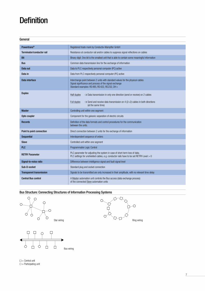
Bus Structure: Connecting Structures of Information Processing Systems
Star wiring Ring wiring
Bus wiring
= Central unit = Participating unit
Powertrans® Registered trade mark by Conductix-Wampfler GmbH
Terminator/conductor rail Resistance at conductor rail and/or cables to suppress signal reflections on cables
Bit Binary digit . One bit is the smallest unit that is able to contain some meaningful information
Bus Common data transmission line for the exchange of information
Data out Data to PLC respectively personal computer (PC) active
Data in Data from PLC respectively personal computer (PC) active
Data interface
Interchange point between 2 units with standard values for the physical cables Signal significance and process of the signal exchange Standard examples: RS 485, RS 422, RS 232, DH +
Duplex
Half duplex Data transmission in only one direction (send or receive) on 2 cables
Full duplex Send and receive data transmission on 4 (2+2) cables in both directions(at the same time)
Master Controlling unit within one segment
opto coupler Component for the galvanic separation of electric circuits
records Definition of the data formats and control procedures for the communicationbetween the units .
Point to point connection Direct connection between 2 units for the exchange of information
Sequential Interdependent sequence of orders
Slave Controlled unit within one segment
PLC Programmable Logic Control
reTrY ParameterPLC parameter for adjusting the system in case of short-term loss of data . PLC settings for unshielded cables, e .g . conductor rails have to be set RETRY-Level > 0
Signal-to-noise ratio Difference between intelligence signal and fault signal level
Sub-D-socket Standard plug and socket connection
Transparent transmission Signals to be transmitted are only increased in their amplitude, with no relevant time delay
Central Bus control A Master automation unit controls the Bus access (data exchange process) of the connected Slave automation units
Definition
General

8
a
cb
Data from PLCData to PLCPower on
No. ... Type / Interface to PLCOptical fibre cables (red) INOptical fibre cables (black) OUT
24 V AC/DC
96
100
84
100
263244
119
5
5.85
Set and System Components
Powertrans® Ib Basic Unit for Interfaces rS 485/422/232, DH +
Powertrans® Ib Interface for Switchboard assembly on Support rail TS 35
Supply voltage
Type of operation
Protect. type
order no.
weight [kg]
230 V - 50 / 60 Hz Half duplex IP 20
051221-303 .2
115 V - 50 / 60 Hz 051221-31
Delivery Support brackets for front or longside installation enclosed .
Interface/ standard
Supply voltage
Protection type
order no.
Dimension [mm] weight [kg]a b c
RS 485
24 V AC / DC IP 20
051231-22109 50 50
0 .15 RS 422
On inquiry RS 232
DH + 051231-20 112 75 45
Powertrans®-Set 230 V / rS 485
Support brackets
Support bracketsCable space
Powertrans®-Set composed of:• 1 x Basic unit 230 V (051221-30)• 1 x Interface-module RS 485 (051231-22)• 1 x Pair of optical fibres cable 0,4 m (051222-4004)Delivery incl . Mounting angle and Instruction manual
Supply voltage
Type of operation
Protect. type
order no.
weight [kg]
230 V - 50 / 60 Hz Half duplex IP 20 3032433 3 .5

9
System Components
Terminator/Conductor rail – in a Case
Connectors/Conductor rail – without Case for Switchboard Installation
resistance value [Ω]
order no.
weight [kg]
150 051213-22010 .5 330 // 330 051213-2203
470 // 470 051213-2204
resistance value [Ω]
order no.
weight [kg]
150 051213-21010 .25 330 // 330 051213-2103
470 // 470 051213-2104
resistance value [Ω]
order no.
weight [kg]
150 051213-2112 0 .25
Terminator/Conductor rail – without Case for Switchboard Installation on Support rail TS 35
Powertrans® Ib Pair of optical Fibers
Length [m]
order no.
20 051222-4200 30 051222-4300 40 051222-4400
Length [m]
order no.
0 .4 051222-4004 5 .0 051222-4050 10 .0 051222-4100
Length [m]
order no.
80 051222-4800 90 051222-4900
Length [m]
order no.
50 051222-4500 60 051222-4600 70 051222-4700
Type on mounting plate
Type on mounting plate
Type on cooling body
35 Pg 13.5
7515
0
200
35
170
170
81
100

10
System Components
Technical Data
Designation Dimensions remarks
Possible data interfaces RS 485 (Profibus), RS 422, RS 232, DH+, etc . Installation for support rails TS 35
Transmission rate
type 187 .5 Kbit accordant to Profibus DP 12 Mbit Bus at a cable length of l > 1000 m (wireloop)
Up to 1 .5 Mbit, acc . to the system config 1000 m wire loop is equivalent to 500 m conductor rail length
Time response no relev . time delay/real time
Length of the system segments typ . < 400 m, depending on the transmission rate Longer lengths on inquiry
Data exchange by 2 poles half duplex operation Projecting for 4 poles Full duplex operation on inquiry
Driver
• No-load voltage ± 70 V potential-free Connecting cross section 0 .75 – 2 .5 mm², shielded
• Short-circuit current 0 .1 to 1 A
receiver
• Input resistance typ . 15 kΩ
• Sensitivity typ . 4 mA
Bus unit per segment Up to 15
opto coupler Insulation 3 kV, 5 mm creep distance
operating data
Basic unit
• Supply voltage 230 V AC, ±10%, 50 / 60 Hz Standard type; connecting cross section . max . 2 .5 mm²
115 V AC, ±10%, 50 / 60 Hz Special type; connecting cross section . max . 2 .5 mm²
• Power absorption typ . 50 VA, 9 VA stand-by
• Max . ambient temperature 0°C to +50°C
• Protection type IP 20 Higher protection type up to IP 65 carried out in the switchboard
Interface
• Supply voltage 24 V AC / DC, ± 10% Connecting cross section max . 2 .5 mm²
• Power absorption 2 VA
Intended Use:Communication between participants in industrial fieldbus networks with Profibus DP, Allen Bradley CH+ or RS 232 interfaces, via conductor rails or reels- and slip rings in indoor systems or protective (IP23) outdoor systems .
requirements for surroundings and conductor rail system:– Double current collectors are mandatory (contact redundancy)– Surroundings have to have low dust and no moisture influence– PLC system has to be adjustable for communication via unshielded bus-cables

11
L3
L2
L1
PE
D2
D1
SPS SPS
D2
D1
Z Z
PT
SPS
PT PT
SPS SPS
D2
D1
Z Z
SPS
PT
PT PT
L1
L2
L3
PE
D1
D2
Single-pole conductor rail
Project, assembly and Starting operationMaximum Lengths for Conductor rails (according to Profibus DP 12 Mbit standard)
recommended Configuration of the Conductor rail
Bus Terminators
System examples 1
During system projecting it is required to observe among other items the maximum parameters for total length, length of feeder cable, number of participating units etc . The maximum values as well as some system examples are shown as follows, for complex systems please consult our engineers .Maximum 15 mobile participating units can operate together with one stationary unit . A larger number of mobile participating units requires a segmentation of the system .The stated lengths are the maximum possible lengths under optimum con-ditions (e .g . straight arrangement, one mobile participating unit, single-pole conductor rail, no contamination etc .) The type of system construction and above mentioned conditions may require a reduction of these lengths .The lengths of annular slip ring systems correspond to those with 3 alleys . If possible, this variation should however be avoided on account of reflections, i .e . with regard to electricity beginning and end should not be connected (pick-up guide for transfer points) .In case of center feed the length of the supply cable to the conductor rail is to be considered as the feeder cable .
Arrangement of the bus terminators at the outlet of the stationary Powertrans® unit or at the beginning of the conductor rail and at the end of the conductor rail . It must be observed that the connecting points of the connection cables of terminators and connections are really at the end of the conductor rail .
arrangement conductor rail Terminator [Ω]
Conductor rail straight, slip ring, annular 150
Conductor rail 2 alleys 150
Conductor rail 3 alleys 330 / 330
Conductor rail 4 alleys 470 / 470
Enclosed conductor rail 0842
Straight arrangement with end feed Straight arrangement with center feed
Length of feeder cables 2 Alleys > 3 Alleys Straight arrangement
500 kbit187,593,7519,29,6
1200 m
1000
800
600
400
200
0
note: rail lengths and maximum data transfer rates are in accordance with the maximum values defined by the Profibus association . Depending on system surroundings, deviations can occur .
note:if possible, keep data lines separated from energy-carrying lines .

12
Z
PT
SPS
Z
PT
SPS
Z
PT
SPS
PT
SPS
SPS
PT
SPS
PT
SPS
PT
SPS
PT
SPS
PT
SPS
PT
Project, assembly and Starting operationSystem examples 2
electric Connection (also see standard connection diagram)
Shielding
Arrangement with 3 alleys
Data transmission along the slip rings
Serial number, e .g . “A38”
For operation without interference we recommend equipping the supply system with a line filter and a differential current control unit . To assure continuity, even when the power supply plug is disconnected, the basic unit is equipped with an additional PE connector (M 5) . This is to provide a protection from electricity arcing from the conductor rail system in case of disturbance .The Powertrans® Ib unit presents a Bus unit . The Sub-D, respectively DH + connection on the interface component, is connected by a shielded cable according to the specifications given by the PLC manufacturer .In principle each Bus segment has to be terminated on both ends . On Profibus applications for example, the Bus terminators in the sockets have to be activated accordingly . On DH + Bus systems, the Bus terminators have to be activated from ”outside”as well .For more information see the operating instructions of the Bus system manufacturers .
Shielding is a method to reduce (damp) electromagnetic environmental influences .Interference currents on cable shield are led off to ground over the shield Bus that has a conductive connection to the ground conductor .In order to avoid that those interference currents might become a source of disturbance themselves, it is very important to provide a low-impedance connection to the protective conductor .In general the shield of the cables should always be connected on both sidesOnly a bilateral connection of the shield will allow good interference suppression in high frequencies .The shield of the data cable is connected according to the specifications of the corresponding PLC manufacturer (often at the socket case) .
Socket (3 poles); net
Annular arrangement
Fiberoptic cables out/in
Earth conductor connection (PE), M 5
Socket (5-poles) conductor rail

13
(+)
(-)
SPS
1)SP
S 1)
SPS
1)
PEL 1
N
BRx
D/Tx
D-P
3Rx
D/Tx
D-N
8A
B A
The
dist
ance
bet
wee
n da
ta c
able
s an
d ad
jace
nt e
nerg
y ca
bles
mus
t not
be
less
than
100
mm
.1) P
LC-s
ettin
gs fo
r uns
hiel
ded
cabl
es/fa
ult t
oler
ance
of d
ata
traffi
c ha
ve to
be
set R
ETRY
-Lev
el >
0
Project, assembly and Starting operationStandard Connection Diagram: application example for Half Duplex (2 poles)
Basic
uni
t
Term
inat
or/
cond
ucto
r rai
l
Inte
rface
Pair
of o
ptica
l fibe
rs
Pow
ertra
ns® Ib
sta
tion
3
Cond
uctix
-Wam
pfler
Pow
ertra
ns® Ib
max
. 2 .5
mm
²
24 V
AC / D
C m
ax . 2
.5 m
m²
Fibe
r opt
ics in
(red
)
Fibe
r opt
ics o
ut (b
lack
)
pre-
man
ufac
ture
d op
tical
fibe
rs
Sock
et
3-po
les
ne
t
- m
in . 0
.75
mm
²-
max
. 2 .5
mm
²-
shie
ldedCo
nnec
tor 5
-pol
es
cond
ucto
r rai
lSi
emen
s Bu
s-co
nnec
tor
Bus-
Term
inat
or
Basic
uni
tIn
terfa
ce-
RS 4
85Si
emen
s S
5 11
5 U
Data
cab
le
Shie
ld
3 gr
een
8 ye
llow
Fibe
r opt
ics in
(red
)
Fibe
r opt
ics o
ut (b
lack
)
Pow
ertra
ns® Ib
st
atio
n 2
Pow
ertra
ns® Ib
st
atio
n 1
Cond
uctix
-Wam
pfler
con
duct
or ra
il
Term
inat
or/
cond
ucto
r rai
l

14
Project, assembly and Starting operationIndicators / (LeD)
Indicator / LeD (Standard)
Power Signifies voltage supply
Monitor (not connected)
Data to PLC Signifies data out: Data from Powertrans® Ib to PLC active
Data from PLC Signifies data in: Data from PLC to Powertrans® Ib active
Direction Signifies the data flow
Red shines data flow from conductor rail to Powertrans® Ib
Red does not shine data flow from Powertrans® Ib to conductor rail
LED flashes in standard operation
Indicator / LeD in Case of Disturbance
Depending on the data transmission rate the LEDs will flash or shine permanently .
Basic unit Interface
LeD at Cause
”Master“ “Slave”Interface Basic unit Basic unit Interface
Conductor rail on one or several Powertrans® 1b-units with polarity reversal
Optical fiber at the “Master”-Powertrans® with polarity reversal
Optical fiber at the “Slave”-Powertrans® with polarity reversal
Supply line to the conductor rail interrupted on one or several participating units
Optical fiber “OUT” at the “Master” basic unit interrupted
Optical fiber “IN” at the “Master” basic unit interrupted
Optical fiber “OUT” at the “Slave” basic unit interrupted
Optical fiber “IN” at the “Slave” basic unit interrupted
Connection of Master-PLC at Powertrans® interrupted
Connection of Slave-PLC at Powertrans® interrupted

15
Project, assembly and Starting operationCause for Disturbance
elimination of Disturbance
Special requirements for DH + Interface Module
1 . Voltage supply at the Powertrans® Ib basic unit/interface not available .2 . Data cable not properly connected .3 . Supply to the transmission medium not properly connected (check polarity reversal!) .4 . Optical fiber not properly connected (check polarity reversal!) .5 . Interruption in the transmission medium (when shutdown or in operation) .6 . Terminators/conductor rail not or falsely connected .7 . Powertrans® Ib basic unit or interface defective .8 . Data traffic is interrupted (Profibus); set RETRY-Level in the PLC to > 0 .
1 . Check voltage supply .2 . Check data cable (position of poles, connection of shielding, connection of the
Bus-terminators according to the specifications of the PLC manufacturer) .3 . Check supply to the conductor rail; connect shielding (see standard connection
diagram) .4 . See standard connection diagram .5 . Check transmission medium (e .g . conductor rails and conductors, couplers, fee-
ding) for continuity . To short cut the transmission medium (e .g . conductor rail) the Powertrans® Ib unit can be directly connected to a two-wire cable for testing .
6 . Control terminators at the beginning and end of the conductor rail .7 . Check proper function of potential equalization, voltage respectively current
between “N” and “PE” must be “0” .8 . For testing the interface the two interfaces can be directly connected (without the
basic unit) by the optical fiber cable . For testing the basic unit the two basic units
Recommendations for using the DH+ interface module:1 . Use at least 2 collectors on each data rail . In case of extreme or dirty environment
3 collectors are recommended . At least space for a third collector should be considered .
2 . Use silver graphite collector shoes .3 . Use datametal conductor rails (stainless steel) .4 . Do not use in extended temperature (beyond 0° to + 50°C) or
corrosive atmosphere environments .5 . Perform maintenance of collector arms, shoes and conductor rails according to
the maintenance instruction of the used conductor rail type, at least every 3 month (dirty contacts and rails, contact wear, contact bounce) .
6 . Refer to A-B publication „Industrial Automation Wiring and Grounding Guidelines for Noise Immunity“, (Publication 1770-4 .1) .
7 . Recommendations relating to DH + cabling and products: • Limit baud rate to 57 .6 K or 115 .2 K • Limit DH + cable length: 1000 ft at 115 .2 K and 2000 ft at 57 .6 K • Limit number of DH + nodes to 16 • Use 82 Ω terminators and daisy chain routing
note!: Some older DH + products are not compatible with 82 Ω
including the following list: • 1771-KA, KA2, KF, KX1 • 1773-KAA, KAB • 1774-KA • 1775-KA, GA, RM, S4A, S4B, SR • 1784-KS • 1785-KA3, -KE (Series A or B), -540 • 8200 products
can be directly connected by cables instead of the conductor rail . Install replace-ment unit, order replacement unit at short notice if required:
• Service number (please request at Conductix-Wampfler by phone) • Company, contact, address • Order and serial number • Description of the fault9 . In general the transmission rate – depending on the application –
should be chosen as low as possible . Adjusting the selection of response times and repeat times during the programming of the Bus-system by the operator can secure its function in particular cases .
8 . Error detection should be implemented by the application: The application program or ladder logic should continually monitor communication errors and retry status (error counts and retry counts) that is provided in A-B products . Errors and retries should not normally occur . If they do, maintenance should be performed as soon as possible .
9 . A device should be programmed or configured only when the device is not moving on the rails .
10 . No claims are made that this equipment is appropriate for any level of safety risks . Safety protection should be provided by the application design using appropriate independent means .
note:„a-B“: allen-Bradley brand of products from rockwell automation, a business of rockwell International Corporation.„DH +“, „Data Highway Plus“, allen-Bradley“ and „PLC“ are trademarks of rockwell automation, a business of rockwell International Corporation.

16
Volume of Delivery
Project, assembly and Starting operation
Personal Security
equipment Security
Mounting of the Basic Unit and Interface
Transport Damage
Basic unit• 1 basic unit with socket (3 poles) for the voltage supply, socket (5 poles) for
the conductor rail connection and 2 pc support brackets .• 1 interface• 1 pair of optical fibers pre-manufactured
Please verify immediately if the material has been delivered completely . The relevant document is the advice note .
Further Informationsee instruction manual BAL0512-0001-E
Please consider the following topics:• Switch off all units/machines/systems that are affected by the assembly .
Disconnect these units/machines/systems from the power supply if required .• Control the correct operation of the safety systems
(e .g . emergency stop buttons)• Install warning signs if required, to avoid starting the operation
unintentionally .• A system must only be programmed and configured while it is
not in operation!
• When starting the operation make sure to apply a voltage of ± 70 V on the data cables!
• After having completed the mounting/repair works, carry out a test run of the systems and check the correct operation of the safety systems!
• Only release systems that work without any fault!• We assume that you are familiar with the appropriate knowledge of mechanics and
electricity!
The data transmission system fulfills the quality requirements of ISO 9001 .Powertrans® Ib units and accessories leave our company – with regard to safety technology - in a perfect condition .Do not open the basic equipment and the interface! Opening the case affects the operational security and voids the warranty!On Powertrans® Ib units the interface entry – and the conductor rail entry – are short-circuit proof .Place the data and current supply cables in such a way that none of the cables will be caught during operation and that no cable will be squashed, bent or damaged in any way .
Transport damage can only be claimed if the supplying company is advised immediately .
Please enclose the following documents to your return shipment:• Service number (please request at Conductix-Wampfler by phone)• Company, contact and address• Order and serial number• Description of the failure
The support brackets of the basic unit can be fixed at the front or long side .Basic unit and interface should be arranged in such a way that any interference from other components (e .g . frequency inverters or relay boards) will be prevented . We recommend a minimum distance of 100 mm .The interface must be fixed on a mounting bar TS 35 (cap bar) .
Basic unit
InterfacePair of optical fibers

Conductor rail / Slip ring Body / Cables
• Conductor rail Slip ring body Cables
• ____ pcs . Point to point connections ____ pcs . Bus coupling(s) ____ pc . Master ____ pc . Slave
• Half duplex (2 poles) Full duplex (4 poles)
• Manufacturer: ______________________________________ Type central unit (Master, unit 1) Interface _________________Manufacturer: ______________________________________ Type central unit (Slave, unit 2) Interface _________________
• Data transmission speed: max . _______________________ k Baud
• System length: ______________ min-1 Travel speed: ______________m/smax . rotational speed: ______________ min-1 or peripheral speed: ______________ m/s
• Cable length from current collector to Powertrans® Ib unit: ______________ m
• Ambient temperature: min . ______________ °C max . ______________ °C
• Environment: outdoor system humidity dustheating acid oilindoor system corrosive vibrations on slip ring bodies
Type of System
Please also note our questionnaire for the dimensioning of conductor rails (always on the last pages of our catalogues) .
Cables
• The following interference could affect the data transmission:
• Details to the size of e .g . high voltage, high frequency:
Please note
For complex systems please enclose a configuration drawing with dimensions of the connecting cables to your inquiry .
Questionnaire | Project Essentials
Data Transmission System Powertrans® IbProgram 0512
Conductix-wampfler GmbH I Rheinstrasse 27+33 I D-79576 Weil am RheinHotline: Phone +49 (0) 7621 / 66 22 22 I Fax +49 (0) 7621 6 62-144 I info .de@conductix .com I www .conductix .comFB-0512-0001c-E
Customer Data
Company: Customer-No .:
FAO:
Address:
Phone: Fax:
E-Mail:
18
Program overview
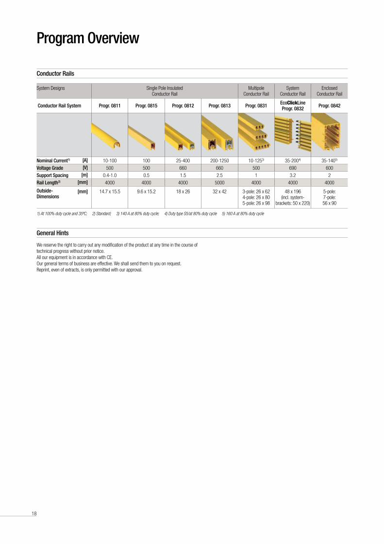
Conductor rails
General Hints
We reserve the right to carry out any modification of the product at any time in the course of technical progress without prior notice .All our equipment is in accordance with CE .Our general terms of business are effective . We shall send them to you on request .Reprint, even of extracts, is only permitted with our approval .
System Designs Single Pole Insulated Conductor Rail
Multipole Conductor Rail
System Conductor Rail
Enclosed Conductor Rail
Conductor rail System Progr. 0811 Progr. 0815 Progr. 0812 Progr. 0813 Progr. 0831 ecoClickLine Progr. 0832 Progr. 0842
nominal Current1) [a] 10-100 100 25-400 200-1250 10-1253) 35-2004) 35-1405)
Voltage Grade [V] 500 500 660 660 500 690 600
Support Spacing [m] 0 .4-1 .0 0 .5 1 .5 2 .5 1 3 .2 2
rail Length 2) [mm] 4000 4000 4000 5000 4000 4000 4000
outside- Dimensions
[mm]
14 .7 x 15 .5
9 .6 x 15 .2
18 x 26
32 x 42
3-pole: 26 x 62 4-pole: 26 x 80 5-pole: 26 x 98
48 x 196 (incl . system-
brackets: 50 x 220)
5-pole: 7-pole: 56 x 90
1) At 100% duty cycle and 35ºC; 2) Standard; 3) 140 A at 80% duty cycle; 4) Duty type S5/at 80% duty cycle 5) 160 A at 80% duty cycle

19
Your applications – our Solutions
Powertrans® Ib Data Transmission Systems from Conductix-Wampfler represent only one of the many solutions made possible by the
broad spectrum of Conductix-Wampfler components for the transport of energy, data and fluid media . The solutions we deliver for your
applications are based on your specific requirements . In many cases, a combination of several different Conductix-Wampfler systems
can prove advantageous . You can count on all of Conductix-Wampfler’s Business Units for hands-on engineering support - coupled
with the perfect solution to meet your energy management and control needs .
Jib booms
Complete with tool transporters, reels,
or an entire media supply system –
here, safety and flexibility are key to
the completion of difficult tasks .
Conductor rails
Whether they‘re enclosed conductor
rails or expandable single-pole
systems, the proven conductor rails
by Conductix-Wampfler reliably move
people and material .
non-insulated conductor rails
Extremely robust, non-insulated
conductor rails with copper heads or
stainless steel surfaces provide the
ideal basis for rough applications, for
example in steel mills or shipyards .
Cable reels
Motorized reels and spring reels by
Conductix-Wampfler hold their own
wherever energy, data and media
have to cover the most diverse
distances within a short amount of
time - in all directions, fast and safe .
Festoon systems
It‘s hard to imagine Conductix-
Wampfler cable trolleys not being
used in virtually every industrial
application . They‘re reliable and
robust and available in an enormous
variety of dimensions and designs .
Conveyor systems
Whether manual, semiautomatic
or with Power & Free – flexibility
is achieved with full customization
concerning layout and location .
reels, retractors and balancers
Whether for hoses or cables, as
classical reels or high-precision
positioning aids for tools, our range
of reels and spring balancers take the
load off your shoulders .
Inductive Power Transfer IPT®
The no-contact system for transferring
energy and data . For all tasks that
depend on high speeds and absolute
resistance to wear .
Slip ring assemblies
Whenever things are really “moving
in circles“, the proven slip ring
assemblies by Conductix-Wampfler
ensure the flawless transfer of energy
and data . Here, everything revolves
around flexibility and reliability!
energy guiding chains
The “Jack of all trades“ when it comes
to transferring energy, data, air and fluid
hoses . With their wide range, these
energy guiding chains are the ideal
solution for many industrial applications .

www.conductix.com
KAT0
512-
0001
d-E
© C
ondu
ctix-
Wam
pfler
| 20
12 |
subj
ect t
o te
chni
cal m
odifi
catio
ns w
ithou
t prio
r not
ice Conductix-wampfler GmbH
Rheinstrasse 27+33
79576 Weil am Rhein
Germany
Hotline
Phone +49 (0) 7621 662-222
Phone +49 (0) 7621 662-0
Fax +49 (0) 7621 662-144
info .de@conductix .com
www .conductix .com