Data sheet SVL product range with butt-weld connection...
56
Data sheet SVL product range with butt-weld connection F DKRCI.PD.F00.A2.02 | 520H8296 | 1 © Danfoss | DCS (MWA) | 2015.09 The new range of products for Industrial Refrigeration - SVL – is based on the successful modular platform concept from the ICF and ICV valves. The SVL products with butt-weld connection F offer flexibility, simplicity and efficiency. The valves are available from a parts program consisting of: - Valve housing with butt-weld connection F in angle or straightway in different sizes. - Five different types of function modules: Shut-off (SVA-S and SVA-L) Hand regulating (REG-S), Check & stop (SCA-X), Check (CHV-X) Strainer (FIA). The function modules fit the same housing and they all have the same high specification. This makes selection, system design and mounting simple and trouble free. • Matching colour of laser engraved aluminium name tag mounted on valve bonnet. • Shared spare parts and modular design reduc- es complexity and stocking costs while allow- ing for fast and easy service. • With multiple applications for a given spare part code number, spare parts inventories will be more flexible, and useful. • If, for some reason, a component has been mounted in the wrong location in the system, it can be quickly solved by replacing the insert. • SVL housing with connection type F is suitable for butt-weld with stainless steel pipes with small thicknesses (2 and 3mm). • One common housing specification makes it very easy to select the right valve for your application and timesaving switch between the functions. • Approved for –60 °C to +150 °C (–76 °F to +302 °F) and up to 52 bar/754 psi (Refer pressure-temperature range chart on page 3 for more detail). • Applicable for sub-critical CO2 and heat pump systems (for selection of valves; please use the chart on page 3). • The new packing gland features static and dynamic sealing components ensuring a unique, tight and secure seal throughout the operating conditions and covering all approved refrigerants and temperatures in the specification. As a result, the SVL products deliver a smooth opening and closing operation, along with very high reliability. • The service kit setup makes selection of spare parts very easy. • The SVL products with Buttweld connection F features coloured seal caps for easy identification of valve function. - Red caps for SVA-S/L shut-off valves - Yellow caps for REG-SA/SB regulating valves - Green caps for SCA-X check & stop valves and CHV-X check valves - Gray caps for FIA strainers. Features
Transcript of Data sheet SVL product range with butt-weld connection...

Data sheet
SVL product range with butt-weld connection F
DKRCI.PD.F00.A2.02 | 520H8296 | 1© Danfoss | DCS (MWA) | 2015.09
The new range of products for Industrial Refrigeration - SVL – is based on the successful modular platform concept from the ICF and ICV valves.
The SVL products with butt-weld connection F offer flexibility, simplicity and efficiency.
The valves are available from a parts program consisting of:- Valve housing with butt-weld connection F in angle or straightway in different sizes.- Five different types of function modules: Shut-off (SVA-S and SVA-L) Hand regulating (REG-S), Check & stop (SCA-X), Check (CHV-X) Strainer (FIA).
The function modules fit the same housing and they all have the same high specification.This makes selection, system design andmounting simple and trouble free.
• Matching colour of laser engraved aluminium name tag mounted on valve bonnet.
• Shared spare parts and modular design reduc-es complexity and stocking costs while allow-ing for fast and easy service.
• With multiple applications for a given spare part code number, spare parts inventories will be more flexible, and useful.
• If, for some reason, a component has been mounted in the wrong location in the system, it can be quickly solved by replacing the insert.
• SVL housing with connection type F is suitable for butt-weld with stainless steel pipes with small thicknesses (2 and 3mm).
• One common housing specification makes it very easy to select the right valve for your application and timesaving switch between the functions.
• Approved for –60 °C to +150 °C (–76 °F to +302 °F) and up to 52 bar/754 psi (Refer pressure-temperature range chart on page 3 for more detail).
• Applicable for sub-critical CO2 and heat pump systems (for selection of valves; please use the chart on page 3).
• The new packing gland features static and dynamic sealing components ensuring a unique, tight and secure seal throughout the operating conditions and covering all approved refrigerants and temperatures in the specification. As a result, the SVL products deliver a smooth opening and closing operation, along with very high reliability.
• The service kit setup makes selection of spare parts very easy.
• The SVL products with Buttweld connection F features coloured seal caps for easy identification of valve function. - Red caps for SVA-S/L shut-off valves - Yellow caps for REG-SA/SB regulating valves - Green caps for SCA-X check & stop valves and CHV-X check valves - Gray caps for FIA strainers.
Features

Data sheet | SVL product range with Butt-weld connection F
DKRCI.PD.F00.A2.02 | 520H8296 | 2© Danfoss | DCS (MWA) | 2015.09
Contents Page
Pressure/Temperature range . . . . . . . . . . . . . . . . . . . . . . . . . . . . . . . . . . . . . . . . . . . . . . . . . . . . . . . . . . . . . . . . . . . . . .3
Available SVL product range with butt-weld connection F . . . . . . . . . . . . . . . . . . . . . . . . . . . . . . . . . . . . . . . .3
Shut-off valves SVA-S and SVA-L . . . . . . . . . . . . . . . . . . . . . . . . . . . . . . . . . . . . . . . . . . . . . . . . . . . . . . . . . . . . . . . . . .4
Features SVA-S and SVA-L . . . . . . . . . . . . . . . . . . . . . . . . . . . . . . . . . . . . . . . . . . . . . . . . . . . . . . . . . . . . . . . . . . . . . . .4
Technical data . . . . . . . . . . . . . . . . . . . . . . . . . . . . . . . . . . . . . . . . . . . . . . . . . . . . . . . . . . . . . . . . . . . . . . . . . . . . . . . . . .4
Connections . . . . . . . . . . . . . . . . . . . . . . . . . . . . . . . . . . . . . . . . . . . . . . . . . . . . . . . . . . . . . . . . . . . . . . . . . . . . . . . . . . .4
Design. . . . . . . . . . . . . . . . . . . . . . . . . . . . . . . . . . . . . . . . . . . . . . . . . . . . . . . . . . . . . . . . . . . . . . . . . . . . . . . . . . . . . . . . . .5
Material specification . . . . . . . . . . . . . . . . . . . . . . . . . . . . . . . . . . . . . . . . . . . . . . . . . . . . . . . . . . . . . . . . . . . . . . . . . . .6
Dimensions and weights . . . . . . . . . . . . . . . . . . . . . . . . . . . . . . . . . . . . . . . . . . . . . . . . . . . . . . . . . . . . . . . . . . . . . . 12
Ordering . . . . . . . . . . . . . . . . . . . . . . . . . . . . . . . . . . . . . . . . . . . . . . . . . . . . . . . . . . . . . . . . . . . . . . . . . . . . . . . . . . . . . 17
Check & stop valves, SCA-X / Check valves, CHV-X. . . . . . . . . . . . . . . . . . . . . . . . . . . . . . . . . . . . . . . . . . . . . . . 19
Features SCA-X and CHV-X . . . . . . . . . . . . . . . . . . . . . . . . . . . . . . . . . . . . . . . . . . . . . . . . . . . . . . . . . . . . . . . . . . . . 19
Technical data . . . . . . . . . . . . . . . . . . . . . . . . . . . . . . . . . . . . . . . . . . . . . . . . . . . . . . . . . . . . . . . . . . . . . . . . . . . . . . . . 19
Connections . . . . . . . . . . . . . . . . . . . . . . . . . . . . . . . . . . . . . . . . . . . . . . . . . . . . . . . . . . . . . . . . . . . . . . . . . . . . . . . . . 19
Design. . . . . . . . . . . . . . . . . . . . . . . . . . . . . . . . . . . . . . . . . . . . . . . . . . . . . . . . . . . . . . . . . . . . . . . . . . . . . . . . . . . . . . . . 20
Computation and selection . . . . . . . . . . . . . . . . . . . . . . . . . . . . . . . . . . . . . . . . . . . . . . . . . . . . . . . . . . . . . . . . . . . 21
Material specification . . . . . . . . . . . . . . . . . . . . . . . . . . . . . . . . . . . . . . . . . . . . . . . . . . . . . . . . . . . . . . . . . . . . . . . . . 23
Application . . . . . . . . . . . . . . . . . . . . . . . . . . . . . . . . . . . . . . . . . . . . . . . . . . . . . . . . . . . . . . . . . . . . . . . . . . . . . . . . . . . 25
Dimensions and weights . . . . . . . . . . . . . . . . . . . . . . . . . . . . . . . . . . . . . . . . . . . . . . . . . . . . . . . . . . . . . . . . . . . . . . 26
Ordering . . . . . . . . . . . . . . . . . . . . . . . . . . . . . . . . . . . . . . . . . . . . . . . . . . . . . . . . . . . . . . . . . . . . . . . . . . . . . . . . . . . . . 29
FIA strainers . . . . . . . . . . . . . . . . . . . . . . . . . . . . . . . . . . . . . . . . . . . . . . . . . . . . . . . . . . . . . . . . . . . . . . . . . . . . . . . . . . . . . 31
Features FIA . . . . . . . . . . . . . . . . . . . . . . . . . . . . . . . . . . . . . . . . . . . . . . . . . . . . . . . . . . . . . . . . . . . . . . . . . . . . . . . . . . 31
Technical data . . . . . . . . . . . . . . . . . . . . . . . . . . . . . . . . . . . . . . . . . . . . . . . . . . . . . . . . . . . . . . . . . . . . . . . . . . . . . . . . 31
Connections . . . . . . . . . . . . . . . . . . . . . . . . . . . . . . . . . . . . . . . . . . . . . . . . . . . . . . . . . . . . . . . . . . . . . . . . . . . . . . . . . 31
Design. . . . . . . . . . . . . . . . . . . . . . . . . . . . . . . . . . . . . . . . . . . . . . . . . . . . . . . . . . . . . . . . . . . . . . . . . . . . . . . . . . . . . . . . 32
Selection of strainer size . . . . . . . . . . . . . . . . . . . . . . . . . . . . . . . . . . . . . . . . . . . . . . . . . . . . . . . . . . . . . . . . . . . . . . 33
Material specification . . . . . . . . . . . . . . . . . . . . . . . . . . . . . . . . . . . . . . . . . . . . . . . . . . . . . . . . . . . . . . . . . . . . . . . . . 35
Dimensions and weights . . . . . . . . . . . . . . . . . . . . . . . . . . . . . . . . . . . . . . . . . . . . . . . . . . . . . . . . . . . . . . . . . . . . . . 36
Ordering . . . . . . . . . . . . . . . . . . . . . . . . . . . . . . . . . . . . . . . . . . . . . . . . . . . . . . . . . . . . . . . . . . . . . . . . . . . . . . . . . . . . . 39
Hand regulating valves REG-SA and REG-SB . . . . . . . . . . . . . . . . . . . . . . . . . . . . . . . . . . . . . . . . . . . . . . . . . . . . 41
Features REG-SA and REG-SB . . . . . . . . . . . . . . . . . . . . . . . . . . . . . . . . . . . . . . . . . . . . . . . . . . . . . . . . . . . . . . . . . . 41
Technical data . . . . . . . . . . . . . . . . . . . . . . . . . . . . . . . . . . . . . . . . . . . . . . . . . . . . . . . . . . . . . . . . . . . . . . . . . . . . . . . . 41
Connections . . . . . . . . . . . . . . . . . . . . . . . . . . . . . . . . . . . . . . . . . . . . . . . . . . . . . . . . . . . . . . . . . . . . . . . . . . . . . . . . . 41
Design. . . . . . . . . . . . . . . . . . . . . . . . . . . . . . . . . . . . . . . . . . . . . . . . . . . . . . . . . . . . . . . . . . . . . . . . . . . . . . . . . . . . . . . . 42
Computation and selection . . . . . . . . . . . . . . . . . . . . . . . . . . . . . . . . . . . . . . . . . . . . . . . . . . . . . . . . . . . . . . . . . . . 43
Material specification . . . . . . . . . . . . . . . . . . . . . . . . . . . . . . . . . . . . . . . . . . . . . . . . . . . . . . . . . . . . . . . . . . . . . . . . . 51
Dimensions and weights . . . . . . . . . . . . . . . . . . . . . . . . . . . . . . . . . . . . . . . . . . . . . . . . . . . . . . . . . . . . . . . . . . . . . . 52
Ordering . . . . . . . . . . . . . . . . . . . . . . . . . . . . . . . . . . . . . . . . . . . . . . . . . . . . . . . . . . . . . . . . . . . . . . . . . . . . . . . . . . . . . 54

DKRCI.PD.F00.A2.02 | 520H8296 | 3© Danfoss | DCS (MWA) | 2015.09
Data sheet | SVL product range with Butt-weld connection F
Pressure/Temperature range Pressure/Temperature range chart for SVL product range with butt-weld connection F
For valve sizes DN 15 to DN 50 and DN 80:52 bar g (754 psi g) at -60°C to +150°C (-76°F to +302°F).
For valve sizes DN 65 and DN100:52 bar g (754 psi g) at -60°C to +100°C (-76°F to +212°F),45 bar g (652 psi g) at +100°C to +150°C (+212°F to +302°F).
For valve size DN 125:52 bar g (754 psi g) at -40°C to +50°C (-40°F to +122°F)43 bar g (623 psi g) at -60°C to -40°C (- 76°F to -40°F),42 bar g (609 psi g) at +50°C to +100°C (+122°F to +212°F),36 bar g (522 psi g) at +100°C to+150°C (+212°F to +302°F).
For valve size DN 150:25 bar g (362 psi g) at -60°C to +150°C (-76°F to +302°F).
For valve size DN 200:25 bar g (362 psi g) at -60°C to +100°C (-76°F to +212°F),23 bar g (333 psi g) at +100°C to +150°C (+212°F to +302°F).
SVL housings with other connection types (DIN, ANSI, SOC and thread) are approved for a maximum working pressure of 52 bar g (754 psi g) at –60°C to +150°C (–76°F to +302°F) for all sizes.
The reduced pressure in some of the SVL housings with connection type F is caused by the welding onto stainless steel pipes with reduced pipe size.
Available SVL products with butt-weld connection FSize [DN]
SVA-S SVA-L SCA-X CHV-X FIA REG-SA REG-SB
ANG STR ANG STR ANG ANG ANG STR ANG STR ANG STR
H-WHEEL CAP H-WHEEL CAP H-WHEEL CAP H-WHEEL CAP CAP CAP CAP CAP CAP CAP
15 X X X X X X X X X X X X X X X X
20 X X X X X X X X X X X X X X X X
25 X X X X X X X X X X X X X X X X
32 X X X X X X X X X X X X X X X X
40 X X X X X X X X X X X X X X X X
50 X X X X X X X X X
65 X X X X X X X X X
80 X X X X X X X X
100 X X X X X X X X
125 X X X X X X X X
150 X X X X X X
200 X X X X X X
X = Available
202326293235384144475053
-60 -30 0 30 60 90 120 150
Pressure / Temperature range
DN 15 to DN 50 + DN 80
DN 65 + DN 100
DN 125
DN 150DN 200
Temperature [°C]
Pres
sure
[bar
]

Data sheet | SVL product range with Butt-weld connection F
DKRCI.PD.F00.A2.02 | 520H8296 | 4© Danfoss | DCS (MWA) | 2015.09
Connections
F Butt-weld connection type F1520
½¾
21.326.9
22
0.8391.059
0.0790.079
7.014.6
4.910.2
8.116.9
5.711.8
253240
11¼1½
33.742.448.3
222
1.3271.6691.902
0.0790.0790.079
24.842.645.2
17.429.831.6
28.849.452.4
20.234.636.7
5065
22½
60.376.1
22
2.373
0.0790.079
80120
6597
93140
76113
80100
34
90.9116.3
33
3.5794.579
0.1180.118
182313
152278
211363
176323
125150200
568
141.7170.3221.1
333
5.5796.7058.705
0.1180.1180.118
514785
1168
470597
1024
596911
1355
545693
1188
Sizemm
Sizein.
ODmm
Tmm
ODin.
Tin.
kv-anglem3/h
kv-straightm3/h
Cv-angleUSgal/min
Cv-straightUSgal/min
• Max. working pressure 52 bar g (754 psi g) for DN15 to DN 125 25 bar g (362 psi g) for DN 150 to DN 200 For more detail on pressure and temperature range; please see page 3.
Technical data • Refrigerants Applicable to HCFC, HFC, R717 (Ammonia) and R744 (CO2). For further information please see installation instruction for SVA.
• Temperature range –60/+150°C (–76/+302°F).
SVA shut-off valves are available in angleway and straightway versions and with Standard neck (SVA-S) and Long neck (SVA-L)
The shut-off valves are designed to meet all industrial refrigeration application requirements and are designed to give favourableflow characteristics and are easy to dismantleand repair when necessary.
The valve cone is designed to ensure perfect closing and withstand a high system pulsation and vibration, which can be present specifically in the discharge line.
• The valves and caps are prepared for sealing, to prevent operation by unauthorized persons, using a seal wire.
• Internal metal backseating: – DN 15 - 65 (½ - 2½ in.) Internal PTFE backseating: – DN 80 - 200 (3 - 8 in.)
• Can accept flow in both directions.• Housing and bonnet material is low tempera-
ture steel according to requirements of the Pressure Equipment Directive and other inter-national classification authorities.
• Equipped with stainless steel bolts.• Classification: DNV, CRN, BV, EAC etc.
To get an updated list of certification on the products please contact your local Danfoss Sales Company.
• Modular Concept: – Each valve housing is available with butt- weld F connection and with several different sizes. – Possible to convert SVA-S or SVA-L to any other product in the FlexlineTM SVL family (regulating valve, check & stop valve, check valve or strainer) just by replacing the complete top part.
• Fast and easy valve overhaul service. It is easy to replace the top part and no welding is needed.
• Optional accessories: – Heavy duty industrial hand wheel for frequent operation. – Cap for infrequent operation.
• Available in angleway and straightway versions with Standard neck or Long neck (DN 15 to DN 40) for insulated systems.
• Each valve type is clearly marked with type, size and performance range.
FeaturesSVA-S and SVA-L
Shut-off valvesSVA-S and SVA-L

DKRCI.PD.F00.A2.02 | 520H8296 | 5© Danfoss | DCS (MWA) | 2015.09
Data sheet | SVL product range with Butt-weld connection F
Design Connection• Butt-weld connection "F"
DN 15 to 65 size: 2mm thick DN 80 -200 size: 3 mm thick
HousingMade of special, cold resistant steel.
Valve coneThe valve cone can be turned on the spindle, thus there will be no friction between the cone and the seat when the valve is opened and closed and the special design will avoid cone spin due to pulsation and vibration when the valve is in open position. A teflon tightening ring provides perfect sealing with minimum closing force.
SpindleMade of polished stainless steel, ideal for leap seal sealing.
Packing glandThe low temperature packing gland ensures a perfect tightness in the range: –60/+150°C (–76/+302°F). The packing glands are equipped with a scraper ring to prevent penetration of dirt and ice into the packing gland.
InstallationIt is recommended that the valves be installed in the direction of flow indicated by the arrow on the valve body. The valve can be installed in the opposite direction but this slightly reduces the kv-value (Cv-value).
Example of Marking Ring
SVA
Nominal bore DN≤ 25 mm (1 in.) DN32-80 mm (1¼ - 3 in.) DN100 - 200 mm (4-8 in.)
Classified for Fluid group I
Category Article 3, paragraph 3 II III
PS 52/754 psig
STOP VALVE
SVA
-S
DN
80/3
”
@ –60°C\–76°F � 150°C\302°F
The valve is designed to withstand high internal pressure. However, the piping system in general should be designed to avoid liquid traps and reduce the risk of hydraulic pressure caused by thermal expansion.
For further information refer to installation instructions for SVA.
Pressure Equipment Directive (PED)SVA valves are approved according to the European standard specified in the Pressure Equipment Directive and are CE marked.For further details / restrictions - see Installation Instruction.

Data sheet | SVL product range with Butt-weld connection F
DKRCI.PD.F00.A2.02 | 520H8296 | 6© Danfoss | DCS (MWA) | 2015.09
Dan
foss
M14
8B00
04_1
Material specification
Danfoss
M148B0097_1
No. Part Material EN ISO ASTM
1 Housing Steel G20Mn5QT, 10213-3------------------------------------P285QH+QT, 10222-4
LCC, A352--------------------------------LF2, A350
2 Bonnet, Flange Steel G20Mn5QT, 10213-3------------------------------------P285QH+QT, 10222-4------------------------------------P275NL, 10028-3
LCC, A352--------------------------------LF2, A350
3 Bonnet, Insert Steel 11SMn3010087
Type 2R 683/9
AISI 1213
4 Spindle Stainless steel X8CrNiS18-910088
Type 17683/13
AISI 303
5 Cone Steel 11SMn3010087
Type 2R 683/9
AISI 1213
8 Packing gland Stainless steel X8CrNiS18-910088
Type 17683/13
AISI 303
9 Packing washer Aluminium
10 O-ring Cloroprene (Neoprene)
11 Spring loaded Teflon ring PTFE
12 Bolts Stainless steel A2-70 A2-70 Type 308
13 Gasket Fiber, Non-asbestos
14 Handwheel Steel
17 Cap Aluminium
18 Gasket for cap Nylon
19 Locking nut Steel
20 Screw Steel
22 Disk spring Steel
SVA-S 15-20 (1/2 - 3/4 in.)

DKRCI.PD.F00.A2.02 | 520H8296 | 7© Danfoss | DCS (MWA) | 2015.09
Data sheet | SVL product range with Butt-weld connection F
Material specification
SVA-S 25-40 (1 - 1½ in.)
Dan
foss
M14
8B00
35_1
Dan
foss
M14
8B00
38_1
No. Part Material EN ISO ASTM
1 Housing Steel G20Mn5QT, 10213-3------------------------------------P285QH+QT, 10222-4
LCC, A352--------------------------------LF2, A350
2 Bonnet, Flange Steel G20Mn5QT, 10213-3------------------------------------P285QH+QT, 10222-4------------------------------------P275NL, 10028-3
LCC, A352--------------------------------LF2, A350
3 Bonnet, Insert Steel 11SMn3010087
Type 2R 683/9
AISI 1213
4 Spindle Stainless steel X8CrNiS18-910088
Type 17683/13
AISI 303
5 Cone Steel 11SMn3010087
Type 2R 683/9
AISI 1213
8 Packing gland Stainless steel X8CrNiS18-910088
Type 17683/13
AISI 303
9 Packing washer Aluminium
10 O-ring Cloroprene (Neoprene)
11 Spring loaded Teflon ring PTFE
12 Bolts Stainless steel A2-70 A2-70 Type 308
13 Gasket Fiber, Non-asbestos
14 Handwheel Steel
17 Cap Aluminium
18 Gasket for cap Nylon
20 Identification ring Stainless steel
21 Disk spring Steel

Data sheet | SVL product range with Butt-weld connection F
DKRCI.PD.F00.A2.02 | 520H8296 | 8© Danfoss | DCS (MWA) | 2015.09
Material specification
SVA-L 15 - 40 (½ - 1½ in.)
No. Part Material EN ISO ASTM
1 Housing Steel G20Mn5QT, 10213-3------------------------------------P285QH+QT, 10222-4
LCC, A352--------------------------------LF2, A350
3 Valve bonnet Steel G20Mn5QT, 10213-3------------------------------------P285QH+QT, 10222-4
LCC, A352--------------------------------LF2, A350
4 Spindle Stainless steel X8CrNiS18-9 10088
Type 17 683/13
AISI 303
5 Cone Steel 11SMn3010087
Type 2R 683/9
AISI 1213
8 Packing gland Stainless steel X8CrNiS18-910088
Type 17683/13
AISI 303
9 Packing washer Aluminium
10 O-ring Cloroprene (Neoprene)
11 Spring loaded Teflon ring PTFE
12 Bolts Stainless steel A2-70 A2-70 Type 308
13 Gasket Fiber, Non-asbestos
14 Hand wheel Steel
17 Cap Aluminium
18 Gasket for cap Nylon (PA6)
20 Identification ring Stainless steel
21 Disk spring Steel
Dan
foss
M14
8B00
40_1
Dan
foss
M14
8B00
41_1

DKRCI.PD.F00.A2.02 | 520H8296 | 9© Danfoss | DCS (MWA) | 2015.09
Data sheet | SVL product range with Butt-weld connection F
Dan
foss
M14
8B00
39_1
Material specification
SVA-S 50-65 (2 - 2½ in.)
Dan
foss
M14
8B00
36_1
No. Part Material EN ISO ASTM
1 Housing Steel G20Mn5QT, 10213-3------------------------------------P285QH+QT, 10222-4
LCC, A352--------------------------------LF2, A350
3 Valve bonnet Steel G20Mn5QT, 10213-3------------------------------------P285QH+QT, 10222-4
LCC, A352--------------------------------LF2, A350
4 Spindle Stainless steel X8CrNiS18-910088
Type 17683/13
AISI 303
5 Cone Steel 11SMn3010087
Type 2R 683/9
AISI 1213
8 Packing gland Stainless steel X8CrNiS18-910088
Type 17683/13
AISI 303
9 Packing washer Aluminium
10 O-ring Cloroprene (Neoprene)
11 Spring loaded Teflon ring PTFE
12 Bolts Stainless steel A2-70 A2-70 Type 308
13 Gasket Fiber, Non-asbestos
14 Handwheel Steel
17 Cap Aluminium
18 Gasket for cap Nylon
19 Locking nut Steel
20 Identification ring Stainless steel
21 Disk spring Steel

Data sheet | SVL product range with Butt-weld connection F
DKRCI.PD.F00.A2.02 | 520H8296 | 10© Danfoss | DCS (MWA) | 2015.09
Danf
oss
M14
8B00
37_1
Material specification
SVA-S 80 - 150 (3 - 6 in.)
No. Part Material EN ISO ASTM
1 Housing Steel G20Mn5QT10213-3
LCCA352
3 Valve bonnet Steel G20Mn5QT, 10213-3------------------------------------P285QH+QT, 10222-4
LCC, A352--------------------------------LF2, A350
4 Spindle Stainless steel X5CrNi18-1010088
Type 11, R 683/13
AISI 304, A276
5 ConeCone seal
SteelTeflon (PTFE)
11SMn3010087
Type 2, R 683/9 AISI 1213
8 Packing gland Stainless steel X8CrNiS18-910088
Type 17R 683/13
AISI 303
9 Packing washer Aluminium
10 O-ring Cloroprene (Neoprene)
11 Spring loaded Teflon ring PTFE
12 Bolts Stainless steel A2-70 A2-70 Type 308
13 Gasket Fiber, Non-asbestos
14 Hand wheel Steel
17 Cap Aluminium
18 Gasket for cap Nylon (PA 6)
19 Soft backseat Teflon (PTFE)
20 Identification ring Stainless steel
22 Disk spring Steel
Dan
foss
M14
8B00
06_1

DKRCI.PD.F00.A2.02 | 520H8296 | 11© Danfoss | DCS (MWA) | 2015.09
Data sheet | SVL product range with Butt-weld connection F
Danf
oss
M14
8B00
07_1
Dan
foss
M14
8B00
06_1
Material specification
SVA-S 200 (8 in.)
No. Part Material EN ISO ASTM
1 Housing Steel G20Mn5QT10213-3
LCCA352
3 Valve bonnet Steel G20Mn5QT, 10213-3------------------------------------P285QH+QT, 10222-4
LCC, A352--------------------------------LF2, A350
4 Spindle Stainless steel X5CrNi18-1010088
Type 11, R 683/13
AISI 304, A276
5 ConeCone seal
SteelTeflon (PTFE)
11SMn3010087
Type 2, R 683/9 AISI 1213
8 Packing gland Stainless steel X8CrNiS18-910088
Type 17R 683/13
AISI 303
9 O-ring Cloroprene (Neoprene)
10 Spring loaded Teflon ring PTFE
11 O-ring Cloroprene (Neoprene)
12 Bolts Stainless steel A2-70 A2-70 Type 308
13 Gasket Fiber, Non-asbestos
14 Hand wheel Steel
15 Washer Stainless steel
16 Nut Stainless steel
17 Cap Aluminium
18 Gasket for cap Nylon (PA 6)
19 Soft backseat Teflon (PTFE)
20 Identification ring Stainless steel
21 Wear ring Teflon (PTFE)
22 Disk spring Steel
23 O-ring PTFE/Cloroprene (Neoprene)

Data sheet | SVL product range with Butt-weld connection F
DKRCI.PD.F00.A2.02 | 520H8296 | 12© Danfoss | DCS (MWA) | 2015.09
Dimensions and weights
SVA-LSVA 15 - 20 mm 63 237 248 45 60 38 60 1.4 kgSVA (½ - ¾) in. 2.48 9.33 9.76 1.77 2.36 1.5 2.36 3.1 lb
SVA 25 - 40 mm 74 296 330 55 80 50 70 2.4 kgSVA (1 - 1½) in. 2.91 11.65 12.99 2.17 3.15 1.97 2.76 5.3 lb
SVA 15 - 40 (½ - 1½ in. ) in angleway version with cap / hand wheel
SVA-xx x x ANG CAP SVA-xx x x ANG H-WHEEL
SVA 15 - 20 mm 4 178 189 45 60 38 60 1.4 kgSVA (½ - ¾) in. 0.16 7.00 7.44 1.77 2.36 1.5 2.36 3.1 lb
SVA 25 - 40 mm 12 234 268 55 80 50 70 2.4 kgSVA (1 - 1½) in. 0.47 9.21 10.55 2.17 3.15 1.97 2.76 5.3 lb
Valve size K Cmax.1 Cmax.2 G ∅D1 ∅D2 H Weight
SVA-S
Specified weights are approximate values only.

DKRCI.PD.F00.A2.02 | 520H8296 | 13© Danfoss | DCS (MWA) | 2015.09
Data sheet | SVL product range with Butt-weld connection F
Dimensions and weights SVA 15 - 40 (½ - 1½ in. ) straightway version with cap / hand wheelSVA-xx x x STR CAP SVA-xx x x STR H-WHEEL
Specified weights are approximate values only.
SVA-S
Valve size K Cmax.1 Cmax.2 Bmax.1 Bmax.2 E G ∅D1 ∅D2 H Weight
SVA 15 - 20 mm 4 146 141 160 156 20 120 60 38 60 2.0 kgSVA (½ - ¾) in. 0.16 5.74 5.55 6.30 6.14 0.79 4.72 2.36 1.50 2.36 4.4 lb
SVA 25 - 40 mm 12 199 208 212 222 26 155 80 50 70 3.0 kgSVA (1 - 1½) in. 0.47 7.83 8.19 8.35 8.74 1.02 6.10 3.15 1.97 2.76 6.6 lb
SVA-LSVA 15 - 20 mm 63 188 184 202 198 20 120 60 38 60 2.0 kgSVA (½ - ¾) in. 2.48 7.40 7.24 7.95 7.80 0.79 4.72 2.36 1.50 2.36 4.4 lb
SVA 25 - 40 mm 74 243 252 256 265 26 155 80 50 70 3.0 kgSVA (1 - 1½) in. 2.91 9.57 9.92 10.08 10.43 1.02 6.10 3.15 1.97 2.76 6.6 lb
Dimensions and weights SVA 50 - 65 (2 - 2½ in.) in angleway version with cap / hand wheel
SVA-xx x x ANG CAP SVA-xx x x ANG H-WHEEL
Valve size K Cmax.1 Cmax.2 G ∅D1 ∅D2 H Weight
Specified weights are approximate values only.
SVA 50 mm 70 284 315 60 100 50 77 3.2 kgSVA (2) in. 2.76 11.18 12.40 2.36 3.94 1.97 3.03 7.1 lb
SVA 65 mm 70 310 335 70 100 50 90 4.8 kgSVA (2½) in. 2.76 12.20 13.19 2.76 3.94 1.97 3.54 10.6 lb
SVA-S

Data sheet | SVL product range with Butt-weld connection F
DKRCI.PD.F00.A2.02 | 520H8296 | 14© Danfoss | DCS (MWA) | 2015.09
Dimensions and weights SVA 50 - 65 (2 - 2½ in.) in straightway version with cap / hand wheel
SVA-xx x x STR CAP SVA-xx x x STR H-WHEEL
Valve size K Bmax.1 Bmax.2 Cmax.1 Cmax.2 E G ∅D1 ∅D2 H Weight
Specified weights are approximate values only.
SVA 50 mm 70 259 259 257 257 32 148 100 50 77 4.2 kgSVA (2) in. 2.76 10.20 10.20 10.12 10.12 1.26 5.83 3.94 1.97 3.03 9.3 lb
SVA 65 mm 70 284 280 284 280 40 176 100 50 90 6.3 kgSVA (2½) in. 2.76 11.18 11.02 11.18 11.02 1.57 6.93 3.94 1.97 3.54 13.9 lb
SVA-S

DKRCI.PD.F00.A2.02 | 520H8296 | 15© Danfoss | DCS (MWA) | 2015.09
Data sheet | SVL product range with Butt-weld connection F
Dimensions and weights SVA 80 - 200 (3 - 8 in.) angleway version with cap / hand wheel
SVA-xx x x ANG CAP SVA-xx x x ANG H-WHEEL
Valve size K Cmax.1 Cmax.2 G ∅D1 ∅D2 ∅H Weight
Specified weights are approximate values only.
SVA 80SVA (3)
mmin.
763.00
37314.69
38815.28
903.54
2007.87
582.28
1295.08
9.7 kg21.4 lb
SVA 100SVA (4)
mmin.
903.54
43217.00
43717.20
1064.17
2509.84
582.28
1566.14
15.3 kg33.7 lb
SVA 125SVA (5)
mmin.
903.54
51720.35
53320.98
1285.04
31512.40
742.91
1937.60
28.1 kg61.9 lb
SVA 150SVA (6)
mmin.
903.54
56422.20
56822.36
1455.71
31512.40
742.91
2198.62
39.7 kg87.5 lb
SVA 200SVA (8)
mmin.
903.54
67526.57
67826.69
1807.09
40015.75
863.39
27610.87
79.5 kg175.3 lb
SVA-S

Data sheet | SVL product range with Butt-weld connection F
DKRCI.PD.F00.A2.02 | 520H8296 | 16© Danfoss | DCS (MWA) | 2015.09
Dimensions and weights SVA 80 - 200 (3 - 8 in.) straightway version with cap / hand wheel
SVA-xx x x STR CAP SVA-xx x x STR H-WHEEL
Valve size K Bmax.1 Bmax.2 Cmax.1 Cmax.2 E G ∅D1 ∅D2 ∅H Weight
Specified weights are approximate values only.
SVA 80SVA (3)
mmin.
763.00
36514.37
32112.64
36714.45
32212.72
481.89
2168.50
2007.87
582.28
1295.08
10.9 kg24.0 lb
SVA 100SVA (4)
mmin.
903.54
43517.13
36714.45
44317.44
37514.76
602.36
26410.39
2509.84
582.28
1566.14
18.2 kg40.1 lb
SVA 125SVA (5)
mmin.
903.54
52620.71
44417.48
53821.18
45617.95
742.91
32212.68
31512.40
742.91
1937.60
32.8 kg72.3 lb
SVA 150SVA (6)
mmin.
903.54
57222.52
48319.02
59423.39
50519.88
913.58
37014.57
31512.40
742.91
2198.62
60.0 kg132.3 lb
SVA 200SVA (8)
mmin.
903.54
69227.24
57922.80
72628.58
61324.13
1174.61
46418.27
40015.75
863.39
27610.87
111.5 kg245.8 lb
SVA-S

DKRCI.PD.F00.A2.02 | 520H8296 | 17© Danfoss | DCS (MWA) | 2015.09
Data sheet | SVL product range with Butt-weld connection F
Ordering
Type codes
Please note that the type codes only serve to identify the valves, some of which may not form part of the standard product range. For further information please contact your local Danfoss Sales Company.
Valve type SVA Shut-off valve
Nominal size in mm Available connections
(valve size measured on the connection diameter)
F
15 DN 15 (½) x
20 DN 20 (¾) x
25 DN 25 (1) x
32 DN 32 (1¼) x
40 DN 40 (1½) x
50 DN 50 (2) x
65 DN 65 (2½) x
80 DN 80 (3) x
100 DN 100 (4) x
125 DN 125 (5) x
150 DN 150 (6) x
200 DN 200 (8) x
Connections F Butt-weld connection: with 2/3 mm thick end connection
Valve housing ANGSTR
Angle flowStraight flow
Other equipment H-WHEELCAP
Hand wheelCap
Size SVA-S SVA-L
15 x x
20 x x
25 x x
32 x x
40 x x
50 x
65 x
80 x
100 x
125 x
150 x
Available connection sizesSVA-S:The S means Standard bonnet length (sizes from DN50 to DN200 are insulation friendly)
SVA-L:The L means Long bonnet length (insulation friendly)
Ordering SVA-Scomplete valvesExample:SVA-S 200 F angleway with hand wheel = 148B6435
SizeType
MWP Code numbermm in. bar psi
Butt-weld connection F150 6 SVA-S 150 F ANG H-WHEEL 25 362 148B6434150 6 SVA-S 150 F ANG CAP 25 362 148B6436200 8 SVA-S 200 F ANG H-WHEEL 25 362 148B6435200 8 SVA-S 200 F ANG CAP 25 362 148B6437
SizeType
MWP Code numbermm in. bar psi
Butt-weld connection F150 6 SVA-S 150 F STR H-WHEEL 25 362 148B6438150 6 SVA-S 150 F STR CAP 25 362 148B6440200 8 SVA-S 200 F STR H-WHEEL 25 362 148B6439200 8 SVA-S 200 F STR CAP 25 362 148B6441
Important!Where products need to be certified according to specific certification societies or where higher pressures are required, the relevant information should be included at the time of order.
SVA-S StraightwaySVA-S Angleway
ANG = AnglewaySTR = StraightwayCAP = CapH-WHEEL = Hand wheel

Data sheet | SVL product range with Butt-weld connection F
DKRCI.PD.F00.A2.02 | 520H8296 | 18© Danfoss | DCS (MWA) | 2015.09
Ordering SVA-S from the parts programme
Example (select from table 1 and 2)
+ =
Valve housing, size 25 (1 in.), butt weld F, angleway,
148B6416Table 1
Top part, SVA-S size 25 (1 in.) with cap
148B5476Table 2
Table 1 SVL valve housings w/different connections
DN 15-65 mm (½ - 2½ in.) DN 80-125 mm (3 - 5 in.)
Sizes [DN] Valve Housing SVL
Butt weld F
mm in. ANG STR
15 ½ 148B6414 148B6424
20 ¾ 148B6415 148B6425
25 1 148B6416 148B6426
32 1¼ 148B6417 148B6427
40 1½ 148B6418 148B6428
50 2 148B6419 148B6429
65 2½ 148B6420 148B6430
80 3 148B6421 148B6431
100 4 148B6422 148B6432
125 5 148B6423 148B6433
Table 2 SVA complete top partincluding gaskets and bolts
Sizes [DN] Complete top part
mm in.SVA-S CAP
SVA-S H-WHEEL
SVA-L CAP
SVA-L H-WHEEL
15 ½148B5276 148B5277 148B5278 148B5279
20 ¾
25 1
148B5476 148B5477 148B5478 148B547932 1¼
40 1½
50 2 148B5728 148B5729
65 2½ 148B5822 148B5823
80 3 148B5916 148B5917
100 4 148B6012 148B6018
125 5 148B6116 148B6117
Please note: Not all sizes available for SVA-L - see table 2.
SVA-S 15-65 with cap
SVA-S 15-65 with h-wheel
SVA-S 80-125 with cap
SVA-S 80-125 with h-wheel
SVA-L 15-40 with cap
SVA-L 15-40 with h-wheel

DKRCI.PD.F00.A2.02 | 520H8296 | 19© Danfoss | DCS (MWA) | 2015.09
Data sheet | SVL product range with Butt-weld connection F
Connections
F Butt-weld connection type F1520
½¾
21.326.9
22
0.8391.059
0.0790.079
8.010.0
9.311.6
253240
11¼1½
33.742.448.3
222
1.3271.6691.902
0.0790.0790.079
24.030.030.0
27.834.834.8
5065
22½
60.376.1
22
2.373
0.0790.079
4572
5385
80100
34
90.9116.3
33
3.5794.579
0.1180.118
103196
129232
125 5 141.7 3 5.579 0.118 301 356
Sizemm
Sizein.
ODmm
Tmm
ODin.
Tin.
kv-anglem3/h
Cv-angleUSgal/min
• Max. working pressure 52 bar g (754 psi g) For more detail on pressure and temperature range; please see page 3.
Technical data • Refrigerants Applicable to HCFC, HFC, R717 (Ammonia) and R744 (CO2). For further information refer to the product instruction for SCA-X/CHV-X.
• Temperature range –60/+150°C (–76/+302°F).
SCA-X are check valves with a built-in stop valve function. CHV-X are check valves only. SCA-X/CHV-X are available in angleway versions. The valves are designed to open at very low differential pressures, allow favourable flow conditions and are easy to disassemble for inspection and service. The SCA-X is equipped with vented cap and has internal backseating enabling the spindle seal to be replaced whilst the valve still under pressure. Laser cut V-ports provide excellent opening characteristics (SCA-X/CHV-X 50-125). The valve cone has a built-in flexibility to ensure a precise and tight closing towards the valve seat. A well balanced dampening effect between the piston and the cylinder gives an optimal protection during low loads and against pulsations.
• Internal backseating enables replacement of the spindle seal whilst the valve is active, i.e. under pressure.
• Optimal flow characteristics ensuring quick opening to the fully open position.
• Protection against pulsation by built-in damp-ing facility.
• Housing and bonnet material is low tempera-ture steel according to requirements of the Pressure Equipment Directive and other inter-national classification authorities.
• Equipped with Stainless steel bolts.• Classification: DNV, CRN, BV, EAC etc.
To get an updated list of certification on the products please contact your local Danfoss Sales Company.
• Modular Concept: – Each valve housing is available with butt- weld F connection and in several different sizes. – Possible to convert SCA-X or CHV-X to any other product in the FlexlineTM SVL family (regulating valve, shut-off valve or strainer) just by replacing the complete top part.
• Fast and easy valve overhaul service. It is easy to replace the top part and no welding is needed.
• Designed to open at a very low differential pressure of 0.04 bar (0.58 psig).
• Designed with a built-in damping chamber preventing valve flutter in case of low refriger-ant velocity and/or low density.
• Each valve is clearly marked with type, size and performance range.
• Easy to disassemble for inspection and service.
FeaturesSCA-X and CHV-X
Check & stop valves, SCA-XCheck valves, CHV-X

Data sheet | SVL product range with Butt-weld connection F
DKRCI.PD.F00.A2.02 | 520H8296 | 20© Danfoss | DCS (MWA) | 2015.09
Design ConnectionsAvailable with the following connections: • Butt-weld connection "F"
DN 15 to 65 size: 2mm thick DN 80 -125 size: 3 mm thick
HousingThe housing is made from special, cold resistant steel.
Valve coneValve cone with built in metallic stop - prevents damage to teflon ring in case of overtightening.
Damping chamberThe chamber is filled with refrigerants (gas or liquid), which provides a damping effect when the valve opens and closes.
Spindle (SCA-X)Made of polished stainless steel, which is ideal for O-ring sealing.
Packing Gland (SCA-X)The “full temperature range” packing gland is the standard for the entire SVL platform.
This ensures perfect tightness throughout the whole temperature range: –60/+150°C (–76/+302°F).
InstallationThe valve must be mounted vertically with the cone downwards.
The valve is designed to resist very high internal pressure. However, the piping system in general should be designed to avoid liquid traps and reduce the risk of hydraulic pressure caused by thermal expansion.
For further information refer to installation instructions for SCA-X/CHV-X.
If cold refrigeration oil having low viscosity enters and settles in the damping chamber, problems with the check valve may arise. Consequently, it may be necessary to modify the valve for more viscous liquids by enlarging the hole to the damping chamber.
Example of marking ring, CHV-X
SCA-X/CHV-X valves
Nominal bore DN = < 25 mm (1 in.) DN32-80 mm (1¼ - 3 in.) DN100 - 125 mm (4 - 5 in.)
Classified for Fluid group I
Category Article 3, paragraph 3 II III
Pressure Equipment Directive (PED)The SCA-X/CHV-X valves are approved according to the European standard specified in the Pressure Equipment Directive and are CE marked.For further details / restrictions - see the product instruction.

DKRCI.PD.F00.A2.02 | 520H8296 | 21© Danfoss | DCS (MWA) | 2015.09
Data sheet | SVL product range with Butt-weld connection F
Computation and selection IntroductionWhen dimensioning SCA-X/CHV-X, it is important to select a valve that is best suited to all operating conditions. Therefore, it is necessary to consider both the nominal and part load working conditions.
Fig. 1
Selection example continued on following page.
.
Example
.
Densitykg/m3
[lb/feet3]
Velocitym/s[ft/min]
Recommendedvelocity
Not recommended
Cmin, rec = 3 m/sCmin, rec = 591 ft/min
ρ = 3.0 kg/m3
ρ = 0.187 lb/feet3
Crec = 14 m/sCrec = 2756 ft/min
SI-UnitsAssumed working conditions:Maximum flow V = 1000 m3/hDensity ρ = 3.0 kg/m3
Minimum part load = 33%
Used expressions:Recommended velocity - Crec [m/s]Minimum recommended velocity - Cmin, rec [m/s]Maximum velocity - Cmax [m/s]Part load velocity - Cpart [m/s]
We know the density ρ ≈ 3.0 kg/m3, consequently Crec as well as Cmin, rec can be found in the figure below (standard valve).
Crec ≈14 m/sCmin, rec ≈ 3 m/s
US-UnitsAssumed working conditions:Maximum flow V = 1160 gpmDensity ρ = 0.187 lb/feet3
Minimum part load = 33%
Used expressions:Recommended velocity - Crec [ft/min]Minimum recommended velocity - Cmin, rec [ft/min]Maximum velocity - Cmax [ft/min]Part load velocity - Cpart [ft/min]
We know the density ρ ≈ 0.187 lb/feet3, consequently Crec as well as Cmin, rec can be found in the figure (standard valve).
Crec ≈ 2756 ft/minCmin, rec ≈ 591 ft/min
The SCA-X/CHV-X valve can be calculated in two ways:– Using the tables below.– Using DIRcalc version 1.14 or higher.

Data sheet | SVL product range with Butt-weld connection F
DKRCI.PD.F00.A2.02 | 520H8296 | 22© Danfoss | DCS (MWA) | 2015.09
Computation and selection (continued)
In conclusion SCA-X in size DN 125 is selected because Cmax ≈ 20 m/s (3900 ft/min) comes nearest to the recommended velocity Crec ≈ 14 m/s (2756 ft/min) and at the same time part load conditions fulfil the requirements, as described:
We know that Cmax ≈ 20 m/s (3900 ft/min) and that minimum part load is 33%. lt fol lows that Cpart ≈ 6.5 m/s (1290 ft/min). Thus, Cpart (6.5 m/s) > Cmin, rec (3.0 m/s) and the sele cted SCA-X model DN125 is the perfect choice.
lf the valve in question (for instance under part load conditions) provides a velocity less than Cmin, rec the valve might start hammering and become noisy. As a result the valve may wear prematurely.
Fig. 2
Knowing that V = 1000 m3/h (1160 gpm) fig. 2 gives the following choices:
For SCA-X/CHV-X in size DN 100 the maximum velocity Cmax ≈ 31 m/s (6100 ft/min)For SCA-X/CHV-X in size DN 125 the maximum velocity Cmax ≈ 20 m/s (3900 ft/min)
.
DN 15 - 40
SCA-
X/CH
V-X
15SC
A-X/
CHV-
X 20
SCA-X
/CHV-X
25
SCA-X/CHV-X 32
SCA-X/CHV-X 40
Dan
foss
M14
8G00
03_1
m/s[ft/min]
m3/h[gpm]
DN 50 - 125
[m/s]
SCA-X/CHV-X 100
SCA-X/CHV-X 125
SCA-
X/CH
V-X
50SC
A-X/
CHV-
X 65
SCA-
X/CH
V-X
80
SCA-X
/CHV-X
100
SCA-X/CHV-X 125
Dan
foss
M14
8G00
04_1
m/s[ft/min]
m3/h[gpm].
.V = 1000 m3/hV = 1160 gpm

DKRCI.PD.F00.A2.02 | 520H8296 | 23© Danfoss | DCS (MWA) | 2015.09
Data sheet | SVL product range with Butt-weld connection F
Material specification
CHV-X 15 - 40
Dan
foss
M14
8G00
09_1
1
2
3
5
14
13
12
6
15
SCA-X 15 - 40
17
8
9
43
12
13
7
14
5
1
16
15
2
6
11
10
Dan
foss
M14
8G00
08_1
No. Part Material DIN/EN ISO ASTM
1 Housing Steel G20Mn5QT, 10213-3 ------------------------------------ P285QH+QT, 10222-4
LCC, A352 ------------------------------------ LF2, A350
2 Bonnet, Flange Steel P275NL1EN10028-3
LF2, A350
3 Bonnet, Insert Steel 11SMn30 10087
Type 2 R 683/9
AISI 1213
4 Spindle Stainless steel X8CrNiS18-9,EN 10088-3
Type 17 683/13
AISI 303
5 Cone SteelTeflon (PTFE)
6 O-ring Cloroprene (Neoprene)
7 Spindle extension Steel
8 Packing glandO-rings
Stainless steel Cloroprene (Neoprene)
X8CrNiS18-9 10088
Type 17 683/13
AISI 303
9 Packing washer Aluminium
10 Spring loaded seal Teflon (PTFE)
11 O-ring Cloroprene (Neoprene)
12 Bolts Stainless steel A2-70 A2-70 Type 308
13 Gasket Fiber, non-asbestos
14 Spring Steel
15 Identification ring Stainless steel
16 Seal cap gasket Nylon
17 Spindle seal cap Aluminium

Data sheet | SVL product range with Butt-weld connection F
DKRCI.PD.F00.A2.02 | 520H8296 | 24© Danfoss | DCS (MWA) | 2015.09
Material specification
CHV-X 50 - 125SCA-X 50 - 125
No. Part Material DIN/EN ISO ASTM
1 Housing DN 50-65 Steel G20Mn5QT, 10213-3 ------------------------------------ P285QH+QT, 10222-4
LCC, A352 --------------------------------LF2, A350
Housing DN 80-125 Steel G20Mn5 QTSEW 685
LCC, A352
2 Gasket Fiber, Non-asbestos
3 SCA-X: Valve bonnetCHV-X: End cover
Steel P285 QH EN 10222-4 ------------------------------------ P275NL1 or 2 EN10028-3
LF2, A350 --------------------------------A, A662
4 Bolts Stainless steel A2-70 A2-70 A-276
5 Tube Steel
6 Seat Steel
7 Valve plate Steel
8 Guide sleeve Steel
9 Spring ring Steel
10 Spring Steel
11 O-ring Cloroprene (Neoprene)
12 Teflon ring Teflon (PTFE)
13 Soft back seal Teflon (PTFE)
14 Spindle DN 50-65 Stainless steel X8CrNiS18-917440
Type 17R 683/13
AISI 303
Spindle DN 80-125 Stainless steel X5CrNi181017440
Type 11683/13
AISI 304A-276
15 Packing gland Stainless steel X8CrNiS18-9, EN 10088-3, Type 17 R 683/13
AISI 303
16 Spindle seal cap and gasket Aluminium
17 Marking label Stainless steel

DKRCI.PD.F00.A2.02 | 520H8296 | 25© Danfoss | DCS (MWA) | 2015.09
Data sheet | SVL product range with Butt-weld connection F
SCA-X
Danf
oss
M14
8G00
05_1
Application Figure 3 shows the check & stop valve SCA-X in the discharge line of a screw compressor unit.The SCA-X valve in the discharge line prevents “back condensation” in the oil separator as well as pressure equalising through the compressor.
Compared to an ordinary stop and check valve arrangement the combined stop/check valve solution, as shown, is easier to install and has lower flow resistance.
Installation of the SCA-X/CHV-X in the economizer line is not recommended.
Oil
sepa
rato
r
Compressor
Oil cooler
Fig. 3

Data sheet | SVL product range with Butt-weld connection F
DKRCI.PD.F00.A2.02 | 520H8296 | 26© Danfoss | DCS (MWA) | 2015.09
Dimensions and weights
SCA-X 15 - 40 CHV-X 15 - 40
SCA-X/CHV-X 15 - 40 (½- 1½ in.)
SCA-X 15 (½ in.)mm 212 45 38 60 60 1.6 kg
3.53 lbin. 8.35 1.77 1.50 2.36 2.36
SCA-X 20 (¾ in.) mm 212 45 38 60 60 1.6 kg3.53 lbin. 8.35 1.77 1.50 2.36 2.36
SCA-X 25 (1 in.) mm 295 55 50 85 70 3.2 kg7.05 lbin. 11.61 2.17 1.97 3.35 2.76
SCA-X 32 (1¼ in.) mm 295 55 50 85 70 3.2 kg7.05 lbin. 11.61 2.17 1.97 3.35 2.76
SCA-X 40 (1½ in.) mm 295 55 50 85 70 3.2 kg7.05 lbin. 11.61 2.17 1.97 3.35 2.76
Valve size C G ∅D Fmin H Weight
SCA-X 15 - 40
CHV-X 15 (½ in.) mm 1034.06
451.77
602.36
602.36
1.2 kg2.65 lbin.
CHV-X 20 (¾ in.) mm 103 45 60 60 1.2 kg2.65 lbin. 4.06 1.77 2.36 2.36
CHV-X 25 (1 in.) mm 143 55 85 70 2.3 kg5.07 lbin. 5.63 2.17 3.35 2.76
CHV-X 32 (1¼ in.) mm 143 55 85 70 2.3 kg5.07 lbin. 5.63 2.17 3.35 2.76
CHV-X 40 (1½ in.) mm 143 55 85 70 2.3 kg5.07 lbin. 5.63 2.17 3.35 2.76
Valve size C G Fmin H Weight
CHV-X 15 - 40
Specified weights are approximate values only.
DKRCI.PD.F00.A2.02 | 520H8296 | 27© Danfoss | DCS (MWA) | 2015.09
Data sheet | SVL product range with Butt-weld connection F
SCA-X/CHV-X 50 - 65 (2 - 2½ in.) Dimensions and weights
SCA-X 50 mm 70 315 60 50 77 3.8 kgSCA-X (2) in. 2.76 12.40 2.36 1.97 3.03 8.40 lb
SCA-X 65 mm 70 335 70 50 90 5.5 kgSCA-X (2½) in. 2.76 12.20 13.19 2.76 3.94 1.97 3.54 12.16 lb
Valve size K C G ∅D H Weight
SCA-X
CHV-X
Specified weights are approximate values only.
Valve size C G Fmin. H Weight
CHV-X 50 mm 132 60 92 77 3.2 kgCHV-X (2) in. 5.20 2.36 3.62 3.03 7.10 lb
CHV-X 65 mm 152 70 107 90 4.5 kgCHV-X (2½) in. 5.98 2.76 4.21 3.54 9.95 lb
Data sheet | SVL product range with Butt-weld connection F
DKRCI.PD.F00.A2.02 | 520H8296 | 28© Danfoss | DCS (MWA) | 2015.09
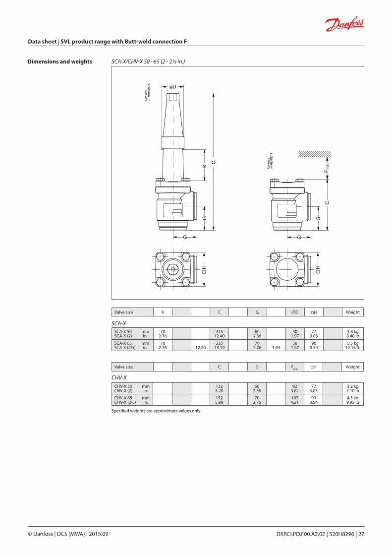
Dimensions and weights SCA-X/CHV-X 80 - 125 (3 - 5 in.)
Dan
foss
M14
8G00
06_1
Dan
foss
M14
8G00
07_1
Valve size K C G ∅D ∅H Weight
SCA-X 80 mm 76 388 90 58 129 9.7 kgSCA-X (3) in. 3.00 15.28 3.54 2.28 5.08 21.4 lb
SCA-X 100 mm 90 437 106 58 156 15.3 kgSCA-X (4) in. 3.54 17.20 4.17 2.28 6.14 33.7 lb
SCA-X 125 mm 90 533 128 74 193 28.1 kgSCA-X (5) in. 3.54 20.98 5.04 2.91 7.60 61.9 lb
SCA-X
CHV-X
Valve size C G Fmin. ∅H Weight
CHV-X 80 mm 189 90 133 129 8.7 kgCHV-X (3) in. 7.44 3.54 5.24 5.08 19.23 lb
CHV-X 100 mm 223 106 163 156 14.3 kgCHV-X (4) in. 8.78 4.17 6.43 6.14 31.60 lb
CHV-X 125 mm 268 128 190 193 25.6 kgCHV-X (5) in. 10.55 5.04 7.48 7.60 56.58 lb
Specified weights are approximate values only.
DKRCI.PD.F00.A2.02 | 520H8296 | 29© Danfoss | DCS (MWA) | 2015.09
Data sheet | SVL product range with Butt-weld connection F
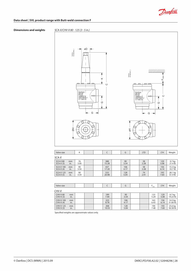
Ordering SVA-X from the parts programme
Example (select from table 1 and 2)
+ =
Valve housing, size 25 (1 in.), butt weld F, angleway,
148B6416Table 1
Top part, SCA-Xsize 25 (1 in.) 148B5482
Table 2
Table 2 SCA-X complete top partincluding gaskets and bolts
Sizes [DN] Complete top part
mm in. SCA-X15 ½
148B528220 ¾
25 1
148B548232 1¼
40 1½50 2 148B573565 2½ 148B582580 3 148B5918
100 4 148B6019125 5 148B6118
SCA-X 15-50 SCA-X 80-125
Table 1 SVL valve housings w/different connections
DN 15-65 mm (½ - 2½ in.) DN 80-125 mm (3 - 5 in.)
Sizes [DN] Valve Housing SVLButt weld F
mm in. ANG STR15 ½ 148B6414 148B642420 ¾ 148B6415 148B642525 1 148B6416 148B642632 1¼ 148B6417 148B642740 1½ 148B6418 148B642850 2 148B6419 148B642965 2½ 148B6420 148B643080 3 148B6421 148B6431
100 4 148B6422 148B6432125 5 148B6423 148B6433

Data sheet | SVL product range with Butt-weld connection F
DKRCI.PD.F00.A2.02 | 520H8296 | 30© Danfoss | DCS (MWA) | 2015.09
Ordering CHV-X from the parts programme
Example (select from table 1 and 2)
+ =
Valve housing, size 25 (1 in.), butt weld F, angleway,
148B6416Table 1
Top part, CHV-Xsize 25 (1 in.) 148B5483
Table 2
Table 2 CHV-X complete top partincluding gaskets and bolts
Sizes [DN] Complete top part
mm in. CHV-X
15 ½148B5283
20 ¾
25 1
148B548332 1¼
40 1½
50 2 148B5747
65 2½ 148B5827
80 3 148B5919
100 4 148B6022
125 5 148B6119
CHV-X 15-50 CHV-X 80-125
Table 1 SVL valve housings w/different connections
DN 15-65 mm (½ - 2½ in.) DN 80-125 mm (3 - 5 in.)
Sizes [DN] Valve Housing SVL
Butt weld F
mm in. ANG STR
15 ½ 148B6414 148B6424
20 ¾ 148B6415 148B6425
25 1 148B6416 148B6426
32 1¼ 148B6417 148B6427
40 1½ 148B6418 148B6428
50 2 148B6419 148B6429
65 2½ 148B6420 148B6430
80 3 148B6421 148B6431
100 4 148B6422 148B6432
125 5 148B6423 148B6433

DKRCI.PD.F00.A2.02 | 520H8296 | 31© Danfoss | DCS (MWA) | 2015.09
Data sheet | SVL product range with Butt-weld connection F
Connections
F Butt-weld connection type F1520
½¾
21.326.9
22
0.8391.059
0.0790.079
253240
11¼1½
33.742.448.3
222
1.3271.6691.902
0.0790.0790.079
5065
22½
60.376.1
22
2.373
0.0790.079
80100
34
90.9116.3
33
3.5794.579
0.1180.118
125150200
568
141.7170.3221.1
333
5.5796.7058.705
0.1180.1180.118
Sizemm
Sizein.
ODmm
Tmm
ODin.
Tin.
• Max. working pressure 52 bar g (754 psi g) for DN15 to DN 125 25 bar g (362 psi g) for DN 150 to DN 200. For more detail on pressure and temperature range; please see page 3.
Technical data • Refrigerants Applicable to HCFC, HFC, R717 (Ammonia) and R744 (CO2). For further information refer to the product instruction for FIA.
• Temperature range –60/+150°C (–76/+302°F).
FIA strainers are a range of angleway and straightway strainers, which are carefully designed to give favourable flow conditions. The design makes the strainer easy to install, and ensures quick strainer inspection and cleaning.
FIA strainers are used ahead of automatic controls, pumps, compressors etc., for initial plant start-up and where permanent filtration of the refrigerant is required. The strainer reduces the risk of undesirable system breakdowns and reduces wear and tear on plant components.
FIA strainers are equipped with a screen mesh of stainless steel, avail able in sizes 100, 150, 250 and 500µ (microns*), (US 150, 100, 72, 38 mesh*).
* Mesh is the number of threads per inch. µ (microns) is the distance between two threads (1µ = 1 /1000 mm).
• FIA 50-200 (2 - 8 in.): A large capacity filter bag (50µ) can be inserted for cleaning plant during commissioning.
• FIA 65-200 (2½ - 8 in.) can be equipped with a magnetic insert for detention of iron particles and other magnetic particles.
• Each strainer clearly marked with type, size and performance range
• Housing and bonnet of low temperature steel in accordance with the requirements of the Pressure Equipment Directive and those of other international classification authorities
• Classification: DNV, CRN, BV, EAC etc. To get an updated list of certification on the products please contact your local Danfoss Sales Company.
• Modular Concept: – Each valve housing is available with butt- weld F connection and with several different sizes. – Possible to convert FIA strainers to any other product in the SVL family (Shut-off valve, regulating valve, check & stop valve or check valve) just by replacing the complete top part.
• Fast and easy overhaul service. It is easy to re-place the top part and no welding is needed.
• Filter net of stainless steel mounted direct without extra gaskets means easy servicing.
• Two types of strainer inserts are available: - A plain insert of stainless steel. - A pleated insert (DN 15-200) with extra large surface, which ensures long intervals between cleaning and low pressure drop.
• FIA 15-40 (½ – 1 ½ in.): A special insert (50µ) can be used in combina-tion with a standard version when cleaning a plant during commissioning.
FeaturesFIA
FIA strainers

Data sheet | SVL product range with Butt-weld connection F
DKRCI.PD.F00.A2.02 | 520H8296 | 32© Danfoss | DCS (MWA) | 2015.09
Design ConnectionsAvailable with the following connections: • Butt-weld connection "F"
DN 15 to 65 size: 2mm thick DN 80 -200 size: 3 mm thick
Strainer InsertA filter grid and filter net of stainless steel ensure long element life. The filter net offers a very high degree of cleanability.
Housing The strainer housing is made of special, cold resistant steel.
Installation/MaintenanceThe strainer is designed to resist high internal pressures. However, the piping system in general should be designed to avoid liquid traps and reduce the risk of hydraulic pressure caused by thermal expansion.Install the strainer with the cover in downward position.
Danfoss recommends replacement/cleaning of the strainer when the differential pressure loss >0.5 bar (7.3 psi) in the liquid line and >0.05 bar (0.7 psi) in the suction line. The max. permissible differential pressure is 1 bar (15 psi).
For further information refer to installation instruction for FIA.
Example of marking ring, FIA
STRAINER
Nominal bore DN ≤ 25 (1 in.) DN 32-80 mm (11/4 - 3 in.) DN 100-200 mm (4-8 in.)
Classified for Fluid group I
Category Article 3, paragraph 3 II III
Pressure Equipment Directive (PED)FIA strainers are approved in accordance with the European standard specified in the Pressure Equipment Directive and are CE marked.For further details / restrictions - see Installation Instruction.

DKRCI.PD.F00.A2.02 | 520H8296 | 33© Danfoss | DCS (MWA) | 2015.09
Data sheet | SVL product range with Butt-weld connection F
All linesFirst start up:.............................................................................................................. 50µ(Use strainer element with removable insert for FIA DN15-40 or separate filter bag for FIA DN 50-200. 50µ insert should normally be removed after the first 24 hours of operation)
Liquid LinesAhead of pumps: ..................................................................................................... 500µ [38 mesh]After pumps: ............................................................................................................. 150µ [100 mesh] / 250µ [72 mesh]In front of AKVA valves .......................................................................................... 100µ [150 mesh]
Protection of automatic regulation equipmentGenerally ................................................................................................................... 150µ [100 mesh] / 250µ [72 mesh]Sensitive equipment, e.g. suction regulators with low temperature ...................................................... 250µ [72 mesh]
Suction LinesAhead of screw compressor ............................................................................... 250µ [72 mesh]Ahead of piston compressor .............................................................................. 150µ [100 mesh]
The mesh aperture size of the strainer must satisfy the requirements stated by the sup pliers of the equipment to be protected.
The following recommendations of aperture size apply in general to refrigeration installations:
Selection of strainer size
DefinitionMesh is the number of threads per inch. µ (microns) is the distance between two threads (1µ = 1 /1000 mm).
Flow coefficient (DIN/ANSI)Connection size (DN)
FIA
µ mesh wire
mm
wire
in.
freespace
%
screen areaPlain elements Pleated elementscm2 in2 cm2 in2
15 - 20(1/2” - 3/4”)
100 0.068 0.003 35 25 3.9 45 7.0150 100 0.10 0.004 36 25 3.9 45 7.0250 72 0.10 0.004 51 25 3.9 45 7.0500 38 0.16 0.006 57.6 25 3.9 45 7.0
25 - 40(1” - 11/2”)
100 0.068 0.003 35 71 11 160 25.0150 100 0.10 0.004 36 71 11 160 25.0250 72 0.10 0.004 51 71 11 160 25.0500 38 0.16 0.006 57.6 71 11 160 25.0
50 (2”)
100 0.068 0.003 35 71 11 200 31.2150 100 0.10 0.004 36 87 13.5 200 31.2250 72 0.10 0.004 51 87 13.5 200 31.2500 38 0.16 0.006 57.6 87 13.5 200 31.2
65 (21/2”)150 100 0.10 0.004 36 127 19.7 305 47.6250 72 0.10 0.004 51 127 19.7 305 47.6500 38 0.16 0.006 57.6 127 19.7 305 47.6
80 (3”)150 100 0.10 0.004 36 205 31.8 450 70.2250 72 0.10 0.004 51 205 31.8 450 70.2500 38 0.16 0.006 57.6 205 31.8 450 70.2
100 (4”)150 100 0.10 0.004 36 370 57.4 790 123.2250 72 0.10 0.004 51 370 57.4 790 123.2500 38 0.16 0.006 57.6 370 57.4 790 123.2
125 (5”)150 100 0.10 0.004 36 510 79.1 1105 172.4250 72 0.10 0.004 51 510 79.1 1105 172.4500 38 0.16 0.006 57.6 510 79.1 1105 172.4
150 (6”)150 100 0.10 0.004 36 726 112.5 1600 249.6250 72 0.10 0.004 51 726 112.5 1600 249.6500 38 0.16 0.006 57.6 726 112.5 1600 249.6
200 (8”)150 100 0.10 0.004 36 1315 203.8250 72 0.10 0.004 51 1315 203.8500 38 0.16 0.006 57.6 1315 203.8
Data sheet | SVL product range with Butt-weld connection F
DKRCI.PD.F00.A2.02 | 520H8296 | 34© Danfoss | DCS (MWA) | 2015.09
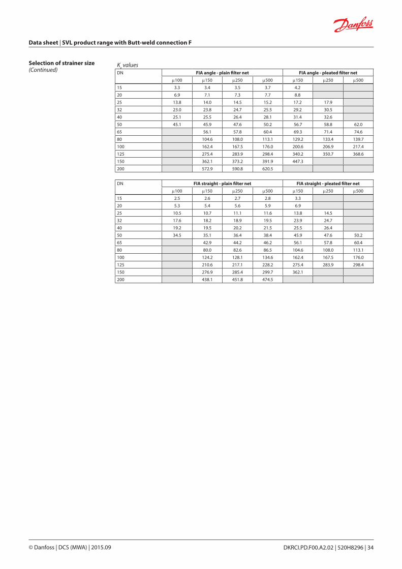
Selection of strainer size(Continued)
Kv valuesDN FIA angle - plain filter net FIA angle - pleated filter net
µ100 µ150 µ250 µ500 µ150 µ250 µ500
15 3.3 3.4 3.5 3.7 4.2
20 6.9 7.1 7.3 7.7 8.8
25 13.8 14.0 14.5 15.2 17.2 17.9
32 23.0 23.8 24.7 25.5 29.2 30.5
40 25.1 25.5 26.4 28.1 31.4 32.6
50 45.1 45.9 47.6 50.2 56.7 58.8 62.0
65 56.1 57.8 60.4 69.3 71.4 74.6
80 104.6 108.0 113.1 129.2 133.4 139.7
100 162.4 167.5 176.0 200.6 206.9 217.4
125 275.4 283.9 298.4 340.2 350.7 368.6
150 362.1 373.2 391.9 447.3
200 572.9 590.8 620.5
DN FIA straight - plain filter net FIA straight - pleated filter net
µ100 µ150 µ250 µ500 µ150 µ250 µ500
15 2.5 2.6 2.7 2.8 3.3
20 5.3 5.4 5.6 5.9 6.9
25 10.5 10.7 11.1 11.6 13.8 14.5
32 17.6 18.2 18.9 19.5 23.9 24.7
40 19.2 19.5 20.2 21.5 25.5 26.4
50 34.5 35.1 36.4 38.4 45.9 47.6 50.2
65 42.9 44.2 46.2 56.1 57.8 60.4
80 80.0 82.6 86.5 104.6 108.0 113.1
100 124.2 128.1 134.6 162.4 167.5 176.0
125 210.6 217.1 228.2 275.4 283.9 298.4
150 276.9 285.4 299.7 362.1
200 438.1 451.8 474.5

DKRCI.PD.F00.A2.02 | 520H8296 | 35© Danfoss | DCS (MWA) | 2015.09
Data sheet | SVL product range with Butt-weld connection F
FIA 15 - 40 (1/2 in. - 1 1/2 in.)
Dan
foss
M14
8H00
14_1
Dan
foss
M14
8H00
15_1
Material specification
FIA 15-40 (1/2 in. - 11/2 in.)No. Part Material DIN ISO ASTM
1 Housing Steel G20Mn5QT, 10213-3------------------------------------P285QH+QT, 10222-4
LCC, A352--------------------------------LF2, A350
2 Gasket Fibre, Non-asbestos
3 Cover Steel P285QH EN10222-4------------------------------------P275NL1 or 2 EN10028-3
LF2, A350--------------------------------A, A662
4 Bolts Stainless steel A2-70 A2-70 Type 308
5 Marking label Aluminium
6 Strainer element Stainless steel
7 Pressure relief (screw) Stainless steel

Data sheet | SVL product range with Butt-weld connection F
DKRCI.PD.F00.A2.02 | 520H8296 | 36© Danfoss | DCS (MWA) | 2015.09
Material specification
FIA 50 - 200 (2 in. - 8 in.)
FIA 50-200 (2 in. - 8 in.)No. Part Material DIN ISO ASTM
1 Housing Steel G20Mn5QT, 10213-3 --------------------------------P285QH+QT, 10222-4
LCC, A352 --------------------------------LF2, A350
2 Gasket Fibre, Non-asbestos
3 Cover Steel P285QH EN10222-4--------------------------------P275NL1 or 2 EN10028-3
LF2, A350--------------------------------A, A662
4 Bolts Stainless steel A2-70 A2-70 Type 308
5 Marking label Aluminium
6 Strainer element Stainless steel
7 Pressure relief (screw) Stainless steel
8* Packing washer Aluminium
* pos 8 used in FIA 50-200
DKRCI.PD.F00.A2.02 | 520H8296 | 37© Danfoss | DCS (MWA) | 2015.09
Data sheet | SVL product range with Butt-weld connection F
StraightwayAngleway
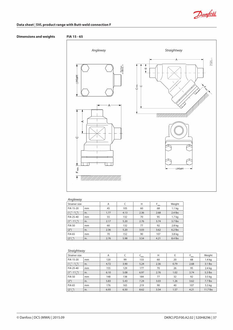
FIA 15 - 65 Dimensions and weights
AnglewayStrainer size A C H Fmin. Weight
FIA 15-20 mm 45 105 60 68 1.1 kg
(1/2" - 3/4") in. 1.77 4.13 2.36 2.68 2.4 lbs
FIA 25-40 mm 55 132 70 95 1.7 kg
(1" - 11/2") in. 2.17 5.20 2.76 3.74 3.7 lbs
FIA 50 mm 60 132 77 92 2.8 kg
(2") in. 2.36 5.20 3.03 3.62 6.2 lbs
FIA 65 mm 70 152 90 107 3.8 kg
(21/2") in. 2.76 5.98 3.54 4.21 8.4 lbs
StraightwayStrainer size A C Cmin. H E Fmin. Weight
FIA 15-20 mm 120 99 133 60 20 68 1.4 kg
(1/2" - 3/4") in. 4.72 3.90 5.24 2.36 0.79 2.68 3.1 lbs
FIA 25-40 mm 155 129 177 70 26 95 2.4 kg
(1" - 11/2") in. 6.10 5.08 6.97 2.76 1.02 3.74 5.3 lbs
FIA 50 mm 148 138 184 77 32 92 3.5 kg
(2") in. 5.83 5.43 7.24 3.03 1.26 3.62 7.7 lbs
FIA 65 mm 176 165 219 90 40 107 5.3 kg
(21/2") in. 6.93 6.50 8.62 3.54 1.57 4.21 11.7 lbs

Data sheet | SVL product range with Butt-weld connection F
DKRCI.PD.F00.A2.02 | 520H8296 | 38© Danfoss | DCS (MWA) | 2015.09
StraightwayAngleway
FIA 80 - 200
Dan
foss
M14
8G00
14_1
Dan
foss
M14
8G00
15_1
Dimensions and weights
AnglewayStrainer size A C H Fmin. Weight
FIA 80 mm 90 189 129 133 7.3 kg
(3") in. 3.54 7.44 5.08 5.24 16.1 lbs
FIA 100 mm 106 223 156 163 11.9 kg
(4") in. 4.17 8.78 6.14 6.42 26.2 lbs
FIA 125 mm 128 268 192 190 21.2 kg
(5") in. 5.04 10.6 7.56 7.48 46.7 lbs
FIA 150 mm 145 303 219 223 30.5 kg
(6") in. 5.71 11.93 8.62 8.78 67.2 lbs
FIA 200 mm 180 372 276 280 68 kg
(8") in. 7.09 14.65 10.87 11.02 150 lbs
StraightwayStrainer size A C Cmin. H E F
min. Weight
FIA 80 mm 216 204 271 129 48 133 8.6 kg
(3") in. 8.50 8.03 10.67 5.08 1.89 5.24 19 lbs
FIA 100 mm 264 256 337 156 60 163 14.9 kg
(4") in. 10.39 10.08 13.27 6.14 2.36 6.42 32.8 lbs
FIA 125 mm 322 313 408 192 74 190 26.9 kg
(5") in. 12.68 12.32 16.06 7.56 2.91 7.48 59.3 lbs
FIA 150 mm 370 370 482 219 91 223 51 kg
(6") in. 14.57 14.57 18.98 8.62 3.58 8.78 112 lbs
FIA 200 mm 464 465 605 276 117 280 95 kg
(8") in. 18.27 18.31 23.82 10.87 4.61 11.02 209 lbs

DKRCI.PD.F00.A2.02 | 520H8296 | 39© Danfoss | DCS (MWA) | 2015.09
Data sheet | SVL product range with Butt-weld connection F
The table below is used to identify the strainer required. Please note that you have to order FIA strainer without element, a strainer element and accessories.
Example:FIA 150 F ANG + FIA-X 150 150μ Strainer Element + Filter Bag = 148B6442 + 148H3134 + 148H3155
F = Butt-weld F
ANG = AnglewaySTR = Straightway
Ordering
Size Type FIAWithoutStrainer Element
Strainer Element
100µ150 mesh
Strainer Element
150µ100 mesh
Strainer Element
250µ72 mesh
Strainer Element
500µ38 mesh
Pleated Strainer element
150µ100 mesh
Pleated Strainer element
250µ72 mesh
Pleated Strainer element
500µ38 meshmm in.
Butt-weld F connection - Angleway 150 6 FIA 150 F ANG 148B6442 - 148H3134 148H3142 148H3148 148H3226 - -200 8 FIA 200 F ANG 148B6443 - 148H3135 148H3143 148H3149 148H3297 - -
Butt-weld F connection - Straightway150 6 FIA 150 F STR 148B6444 - 148H3134 148H3142 148H3148 148H3226 - -200 8 FIA 200 F STR 148B6445 - 148H3135 148H3143 148H3149 148H3297 - -
Part Accessory for Code number
Magnet insertFIA 65-100 148H3447FIA 125-200 148H3448
Part Accessory for Code number
Strainer element µ150 with removable element µ50 for the first start up
FIA 15-20 148H3301
FIA 25-40 148H3302
Part Accessory for Code number
Filter bag
FIA 50 148H3150FIA 65 148H3151FIA 80 148H3152FIA 100 148H3153FIA 125 148H3154FIA 150 148H3155FIA 200 148H3156
Part Accessory for Code numberPurge valve complete
FIA 50 - 300148B3745
Blind nut with gasket 148H3450
Accessories

Data sheet | SVL product range with Butt-weld connection F
DKRCI.PD.F00.A2.02 | 520H8296 | 40© Danfoss | DCS (MWA) | 2015.09
Ordering FIA strainers from the parts programme
Example (select from table 1 and 2)
+
+
=Strainer Housing, size 25 (1 in.),
butt weld F, angleway, 148B6416
Table 1
Top part, FIA, size 25 (1 in.) 148B5484
+Strainer insert, 250µ, 72 mesh
148H3127Table 2
Table 2 FIA complete top part including gaskets and bolts
Sizes [DN]
Complete top partFIA
mm in.
15 ½148B5284
20 ¾
25 1
148B548432 1¼
40 1½
50 2 148B5748
65 2½ 148B5832
80 3 148B5922
100 4 148B6024
125 5 148B6122
FIA 15-65 FIA 80-125
Strainer Element
100µ150 mesh
Strainer Element
150µ100 mesh
Strainer Element
250µ72 mesh
Strainer Element
500µ38 mesh
Pleated Strainer element
150µ100 mesh
Pleated Strainer element
250µ72 mesh
Pleated Strainer element
500µ38 mesh
+ 148H3122 148H3124 148H3126 148H3128 148H3303 - -
+ 148H3123 148H3125 148H3127 148H3129 148H3304 148H3269 -
+ 148H3157 148H3130 148H3138 148H3144 148H3179 148H3184 148H3189
+ - 148H3131 148H3139 148H3145 148H3180 148H3185 148H3190
+ - 148H3119 148H3120 148H3121 148H3181 148H3186 148H3191
+ - 148H3132 148H3140 148H3146 148H3182 148H3187 148H3192
+ - 148H3133 148H3141 148H3147 148H3183 148H3188 148H3193
Table 1 SVL valve housings w/different connections
DN 15-65 mm (½ - 2½ in.) DN 80-125 mm (3 - 5 in.)
Sizes [DN] Valve Housing SVL
Butt weld F
mm in. ANG STR
15 ½ 148B6414 148B6424
20 ¾ 148B6415 148B6425
25 1 148B6416 148B6426
32 1¼ 148B6417 148B6427
40 1½ 148B6418 148B6428
50 2 148B6419 148B6429
65 2½ 148B6420 148B6430
80 3 148B6421 148B6431
100 4 148B6422 148B6432
125 5 148B6423 148B6433

DKRCI.PD.F00.A2.02 | 520H8296 | 41© Danfoss | DCS (MWA) | 2015.09
Data sheet | SVL product range with Butt-weld connection F
Connections
F Butt-weld connection type F1520
½¾
21.326.9
22
0.8391.059
0.0790.079 A and B
253240
11¼1½
33.742.448.3
222
1.3271.6691.902
0.0790.0790.079
A and B
5065
22½
60.376.1
22
2.373
0.0790.079
BB
Sizemm
Sizein.
ODmm
Tmm
ODin.
Tin. Cone
• Max. working pressure 52 bar g (754 psi g) For more detail on pressure and temperature range; please see page 3.
Technical data • Refrigerants Applicable to HCFC, HFC, R717 (Ammonia) and R744 (CO2). For further information refer to the product instruction for REG-SA and REG-SB.
• Temperature range –60/+150°C (–76/+302°F).
REG-SA and REG-SB are angleway and straightway hand regulating valves, which act as normal stop valves in closed position.
The valves are available in two different versions – REG-SA and REG-SB designed for regulation purposes in liquid and expansion lines.
The valves are designed to meet the strict quality requirements on refrigerating installations specified by the international classification societies and are carefully designed to present favourable flow conditions and accurate linear characteristics.
REG-SA and REG-SB are equipped with vented cap and internal backseating enables replacement of the spindle seal whilst the valve is active, i.e. under pressure.
• Long neck versions (DN 15 to DN 40) for insu-lated systems available from parts programme.
• Acts as a normal stop valve in closed position.• Housing and bonnet material is low tempera-
ture steel according to requirements of the Pressure Equipment Directive and other inter-national classification authorities.
• Exact capacity and setting of the valve can be calculated for all refrigerants by means of "DIR-calc™" (Danfoss Industrial Refrigeration calcula-tion programme).
• Classification: DNV, CRN, BV, EAC etc. To get an updated list of certification on the products please contact your local Danfoss Sales Company.
• Modular Concept: – Each valve housing is available with butt- weld F connection and in several different sizes. – Possible to convert REG-SA or REG-SB to any other product in the FlexlineTM SVL family (shut-off valve, check & stop valve, check valve or strainer) just by replacing the complete top part.
• Fast and easy valve overhaul service. It is easy to replace the top part and no welding is needed.
• Designed to ensure perfect regulation• Internal backseating enables replacement of
the spindle seal whilst the valve is active, i.e. under pressure.
• Easy to disassemble for inspection and possible repair.
FeaturesREG-SA and REG-SB
Hand regulating valvesREG-SA and REG-SB

Data sheet | SVL product range with Butt-weld connection F
DKRCI.PD.F00.A2.02 | 520H8296 | 42© Danfoss | DCS (MWA) | 2015.09
Design HousingHousing is Standard SVA angleway or straightway housing allowing other inserts from the SVL platform to be installed.Material is special, cold resistant steel
ConnectionsAvailable with the following connections:• Butt-weld connection "F"
DN 15 to 65 size: 2mm thick
The coneThe valves are available in two different versions – REG-SA with an A cone and REG-SB with a B cone. The A cone is designed for expansion lines, while the B cone is designed for regulating purposes e.g. liquid lines.
The valve cone is designed to ensure perfect regulation and provide an extensive regulating area. Irrespective of the refrigerant used, it is easy to obtain the correct capacity. A cone seal ring provides perfect sealing at a minimum closing momentum.
The valve cone can be turned on the spindle, thus there will be no friction between the cone and the seat when the valve is opened and closed. SpindleThe spindle is made of polished stainless steel, which is ideal for O-ring sealing.
Packing gland - REG-SA and REG-SBThe “full temperature range” packing gland ensures perfect tightness in the whole range: –60/+150°C (–76/+302°F). The packing glands are equipped with a scraper ring to prevent penetration of dirt and ice.
InstallationInstall the valve with the spindle up or in horizontal position. The flow must be directed towards the cone.
The valve is designed to withstand high internal pressure. However, the piping system in general should be designed to avoid liquid traps and reduce the risk of hydraulic pressure caused by thermal expansion.
For further information refer to product instruction for REG-SA and REG-SB.
Pressure Equipment Directive (PED)REG valves are approved according to the European standard specified in the Pressure Equipment Directive and are CE marked.
Example of marking ring, REG-SA
REG-SA and REG-SB valves
Nominal bore DN = < 25 mm (1 in.) DN32-65 mm (1¼ - 2½ in.)
Classified for Fluid group I
Category Article 3, paragraph 3 II

DKRCI.PD.F00.A2.02 | 520H8296 | 43© Danfoss | DCS (MWA) | 2015.09
Data sheet | SVL product range with Butt-weld connection F
Computation and selection
Sizing regulating valve for liquid flowLiquid refrigerants: Use the liquid tables, fig. 6 - 10. For other refrigerants and brines, "Normal flow" (Turbulent flow); see below and use the flow coefficient tables (fig. 1 - 5).
IntroductionIn refrigeration plants, regulating valves are primarily used in liquid lines in order to regulate the flow of refrigerant. The valves can, however, also be used as expansion valves. From a calculation point of view the two fields of application are very different.
Normal flow is the term used to describe the general case where the flow through the valve is proportional to the square root of the pressure drop across it and inversely proportional to the density of the refrigerant (Bernouillis equation).
This relationship between mass flow, pressure drop and density satisfies the majority of all valve applications with refrigerants and brines.
Normal flow is characterised by turbulent flow through the valve without any phase change. The following capacity curves are based on the above mentioned assumption.
Application of the regulating valves outside the normal flow area will reduce the capacity of the valve considerably. In such cases it is recommended to use "DIRcalc™" (Danfoss Industrial Refrigeration calculation programme).
Cv [US gal/min] Quantity [US gal/min] of water flowing through a valve at a pressure loss of 1 psi.
P1 [psi] Pressure before the valve (upstream).
P2 [psi] Pressure after the valve (downstream).
∆p [psi] Actual pressure loss across the valve (P1–P2).
G [lb/min] Mass flow through the valve. [US gal/min] Volume flow through the
valve.ρ [lb/ft3] Density of the refrigerant
before the valveCA Calculation factor (fig. 11).
Location of valve in system (marked with grey)
Hot gas by-pass & defrost line
Discharge line
Wet suction lineDry suction line
Liquid line without phase change Liquid line with or without phase change
REG
kv [m3/h] Quantity [m3/h] of water flowing through a valve at a pressure loss of 1 bar (according to VDE/VDI Norm 2173).
P1 [bar] Pressure before the valve (upstream).
P2 [bar] Pressure after the valve (downstream).
∆p [bar] Actual pressure loss across the valve (P1–P2).
G [kg/h] Mass flow through the valve. [m3/h] Volume flow through the valve.ρ [kg/m3] Density of the refrigerant before
the valve.CA Calculation factor (fig. 11).
SI-units
Mass flow:
Volume flow:
Imperial units
Mass flow:
Volume flow:

Data sheet | SVL product range with Butt-weld connection F
DKRCI.PD.F00.A2.02 | 520H8296 | 44© Danfoss | DCS (MWA) | 2015.09
Computation and selection
Flow coefficient
B
A
00
0% 25% 50% 75% 100%
Turn of spindle
Opening
Kv (Cv)
0.5
1
1.5
2
2.5
3
3.5
4
4.5
5
1 2 3 4 5 6 7 8 9
(5.80)
(5.22)
(4.64)
(4.06)
(3.48)
(2.90)
(2.32)
(1.74)
(1.16)
(0.58)
REG-SA 15-20 and REG-SB 15-20
Fig. 1
Flow coefficientREG-SA 25-40 and REG-SB 25-40
B
A
0% 25% 50% 75% 100%
Turn of spindle
Opening
Kv (Cv)
0
2
4
6
8
10
12
14
16
18
20
0 1 2 3 4 5 6 7 8 9 10 11 12
(23.20)
(20.88)
(18.56)
(16.24)
(13.92)
(11.60)
(9.28)
(6.96)
(4.64)
(2.32)
Fig. 2

DKRCI.PD.F00.A2.02 | 520H8296 | 45© Danfoss | DCS (MWA) | 2015.09
Data sheet | SVL product range with Butt-weld connection F
Flow coefficient
B
0% 25% 50% 75% 100%
Turn of spindle
Opening
Kv (Cv)
0
5
10
15
20
25
30
35
40
45
0 1 2 3 4 5 6 7 8 9 10 11 12 13
(52.2)
(46.4)
(40.6)
(34.8)
(29.0)
(23.2)
(17.4)
(11.6)
(5.8)
REG-SB 50
Fig. 3
Computation and selection (Continued)
Flow coefficientREG-SB 65
B
0% 25% 50% 75% 100%
Turn of spindle
Opening
Kv (Cv)
0
10
20
30
40
50
60
70
80
0 1 2 3 4 5 6 7 8 9 10 11 12 13 14 15
(92.8)
(81.2)
(69.6)
(58.0)
(46.4)
(34.8)
(23.2)
(11.6)
Fig. 4

Data sheet | SVL product range with Butt-weld connection F
DKRCI.PD.F00.A2.02 | 520H8296 | 46© Danfoss | DCS (MWA) | 2015.09
Computation and selection(Continued)
Liquid R 717, density: 670 kg/m3 [42 lb/ft3]
For choice of valve size and connection see "Connections".
REG-SA 15-20 and REG-SB 15-20
0
1
2
3
4
5
6
7
8
9
0%
25%
50%
75%
100%
Turn of spindle A B
Turn of spindle
Opening
∆P = 2 bar (29 psi)∆P = 1.5 bar (22 psi)∆P = 1 bar (14 psi)
∆P = 0.5 bar (7 psi)
kg/h(lb/min)
8000(294)
4000(147)
RRRRRRRRRRRRRRRRR777777777771111111177777777777
Fig. 5
REG-SA 25-40 and REG-SB 25-40
∆P = 2 bar (29 psi)∆P = 1.5 bar (22 psi)∆P = 1 bar (14 psi)
∆P = 0.5 bar (7 psi)
kg/h(lb/min)
30000(1103)
20000(735)
BA
10000(368)
0
1
2
3
4
5
6
7
8
9
10
11
12
Turn of spindle
RRRR77771117777
Opening
0%
25%
50%
75%
100%
Fig. 6

DKRCI.PD.F00.A2.02 | 520H8296 | 47© Danfoss | DCS (MWA) | 2015.09
Data sheet | SVL product range with Butt-weld connection F
For choice of valve size and connection see "Connections".
Computation and selection(Continued)
Liquid R 717, density: 670 kg/m3 [42 lb/ft3]
REG-SB 50
∆P = 2 bar (29 psi)∆P = 1.5 bar (22 psi)∆P = 1 bar (14 psi)
∆P = 0.5 bar (7 psi)
kg/h(lb/min)
60000(2206)45000(1654)
B
30000(1103)15000
(551)
Turn of spindle
R7170
1
2
3
4
0%
25%
50%
75%
100%
5
6
7
8
9
10
11
12
13 Opening
Fig. 7
REG-SB 65
∆P = 2 bar (29 psi)∆P = 1.5 bar (22 psi)∆P = 1 bar (14 psi)
∆P = 0.5 bar (7 psi)
kg/h(lb/min)100000
(3676)75000(2757)
B
50000(1838)25000
(919)
Turn of spindle
R717012
6
0%
25%
50%
75%
100%
3
4
5
7
8
9
10
1112
13
14
15 Opening
Fig. 8

Data sheet | SVL product range with Butt-weld connection F
DKRCI.PD.F00.A2.02 | 520H8296 | 48© Danfoss | DCS (MWA) | 2015.09
Calculation factor CA
For choice of valve size and connection see "Connections".
Computation and selection(Continued)
Liquid R 717, density: 670 kg/m3 [42 lb/ft3]
Fig. 9

DKRCI.PD.F00.A2.02 | 520H8296 | 49© Danfoss | DCS (MWA) | 2015.09
Data sheet | SVL product range with Butt-weld connection F
Flow rate diagram
Refrigerant: R 717Refrigerant flow: 2200 kg/hPressure drop: ∆p = 0.5 bar
The above mentioned example is illustrated on the following flow rate diagram and shows that REG-SB 15 and 20 with cone B can be used. The main rule is that nominal regulation range should be below 85% opening degree. If the arrowline is crossing 2 cone curves, the smaller cone should be selected if opening degree < 85%.
The example is only correct if the density of the refrigerant is approx. 670 (kg/m3), and there must be no build-up of flash gas in the valve.
Computation and selectionExample 1.
REG-SA 15-20 and REG-SB 15-20
2200(81)
0
1
2
3
4
5
6
7
8
9
0%
25%
50%
75%
100%
Turn of spindle A B
Turn of spindle
Opening
∆P = 2 bar (29 psi)∆P = 1.5 bar (22 psi)∆P = 1 bar (14 psi)
∆P = 0.5 bar (7 psi)
kg/h(lb/min)
8000(294)
4000(147)
RRRRRRRRRRRRRRRRR777777777771111111177777777777
Fig. 10

Data sheet | SVL product range with Butt-weld connection F
DKRCI.PD.F00.A2.02 | 520H8296 | 50© Danfoss | DCS (MWA) | 2015.09
Computation and selectionExample 2.
Brine, density ρ: 1150 [kg/m3]Brine flow G: 2,700 [kg/h]Pressure drop ∆p: 0.5 [bar]
In this example it is not possible to use the selection diagrams (fig. 5 - 8) as the refrigerant in question is not included.
Use the curves of the kv-values instead (fig. 1 - 4) and calculate the required kv by means of the formulas in the "Introduction" passage at the beginning of this chapter. Alternatively calculate the kv-values by means of the calculation factor CA (fig. 11) and the flow rate diagram (in this example: fig. 12) as per the following calculation example.
Required kv-valueCA = 0.00132 (from fig. 18)kv = CA × Gkv = 0.00132 × 2,700 [kg/h] = 3.56 [m3/h]
Calculation example:
Flow rate diagram
Calculation factor CA
Density kg/m3 [lb/ft]
REG-SB 15 and REG-SB 20 with cone B can be used.
B
A
00
0% 25% 50% 75% 100%
Turn of spindle
Opening
Kv (Cv)
0.5
1
1.5
2
2.5
3
3.5
4
4.5
5
1 2 3 4 5 6 7 8 9
(5.80)
(5.22)
(4.64)
(4.06)
(3.48)
(2.90)
(2.32)
(1.74)
(1.16)
(0.58)
Fig. 11
Fig. 12
3.56 m3/h (from calculation above)

DKRCI.PD.F00.A2.02 | 520H8296 | 51© Danfoss | DCS (MWA) | 2015.09
Data sheet | SVL product range with Butt-weld connection F
No. Part Material EN ISO ASTM
1 Housing Steel G20Mn5QT, 10213-3 ------------------------------------ P285QH+QT, 10222-4
LCC, A352 ------------------------------------ LF2, A350
2 DN 15 - 40 (½ - 1½ in.)– Bonnet, Flange
Steel P275NL1 or 2 EN10028-3 A, A662
3A DN 15 - 40 (3/8 - 1½ in.)– Bonnet, Insert
Steel 11SMn3010087
Type 2, R 683-9 1213SAE J403
3B DN 50 - 65 (2 - 2½ in.)– Bonnet, Flange
Steel P285QH+QT10222-4
LF2A350
4 SpindleDN 15 - 65 (¼ - 2½ in.)
Stainless steel X8CrNiS 18-9, 17440 Type 17, 683/13 AISI 303
5 Cone Steel
7 Packing washer Aluminium
8 Packing gland Stainless Steel X8CrNiS 18-9, 10088 Type 17, 683/13 AISI 303
9 O-ring Cloroprene (Neoprene)
10 Spring loaded Teflon ring PTFE
11 O-ring Cloroprene (Neoprene)
12 Bolts Stainless steel A2-70 A2-70 Type 308
13 Gasket Fiber, non asbestos
14 Bottom insert Steel
17 Seal cap Aluminium
18 Gasket f. seal cap Nylon
19 Locking nut Steel
20 Screw Steel
21 Disk spring Steel
Material specification
Dan
foss
M14
8B00
10_1
17
1118
810 97
12
213
3A4
1
21
5
REG-SA and REG-SB 15 - 40 REG-SA and REG-SB 50 - 65
Dan
foss
M14
8B00
11_1
21
7
3B

Data sheet | SVL product range with Butt-weld connection F
DKRCI.PD.F00.A2.02 | 520H8296 | 52© Danfoss | DCS (MWA) | 2015.09
Dimensions and weights REG-SA and REG-SB 15 - 65 in angleway version
Specified weights are approximate values only.
REG-SA and REG-SB 15 - 40 REG-SB 50 - 65
Valve size C G ∅D H Weight
REG-SA/SB 15-20REG-SA/SB (½-3/4)
mmin.
1827.17
451.77
381.50
602.36
1.4 kg3.1 lb
REG-SA/SB 25-40REG-SA/SB (1-1½)
mmin.
2379.33
552.17
501.97
702.76
2.4 kg5.3 lb
REG-SB 50 REG-SB (2 in.)REG-SB 65 REG-SB (2½ in.)
mmin.
mmin.
31512.4335
13.19
602.3670
2.76
501.9750
1.97
773.0390
3.54
3.2 kg7.1 lb4.8 kg10.6 lb
REG-SA/SB 32 SOCREG-SA/SB (1¼ in.) SOCREG-SA/SB 40 SOCREG-SA/SB (1½ in.) SOCREG-SB 50 SOC REG-SB (2 in.) SOC
mmin.
mmin.
mm.in.
27510.83275
10.83320
12.60
622.4462
2.4465
2.56
501.9750
1.9750
1.97
702.7670
2.7677
3.03
2.9 kg6.4 lb2.9 kg6.4 lb4.1 kg9.0 lb

DKRCI.PD.F00.A2.02 | 520H8296 | 53© Danfoss | DCS (MWA) | 2015.09
Data sheet | SVL product range with Butt-weld connection F
Dimensions and weights(cont.)
REG-SA and REG-SB 15 - 65 in straightway version
REG-SA and REG-SB 15 - 40
Specified weights are approximate values only.
Valve size C B E G ∅D H Weight
REG-SA/SB 15-20REG-SA/SB (½-3/4)
mmin.
1455.71
1556.10
200.79
1204.72
381.50
602.36
2.0 kg4.4 lb
REG-SA/SB 25-40REG-SA/SB (1-1½)
mmin.
2007.87
2158.46
261.02
1556.10
501.97
702.76
3.0 kg6.6 lb
REG-SB 50 REG-SB (2 in.)REG-SB 65 REG-SB (2½ in.)
mmin.
mmin.
25710.12280
11.02
25010.20284
11.18
321.2640
1.57
1485.831766.93
501.9750
1.97
773.0390
3.54
4.2 kg9.3 lb6.3 kg13.9 lb
REG 32 SOC REG (1¼) SOCREG 40 SOCREG (1½) SOCREG-SB 50 SOC REG-SB (2 in.) SOC
mmin.
mmin.
mmin.
2098.232138.39261
10.28
2228.742228.74266
10.47
27.41.0831.01.2237
1.26
1556.101556.101626.38
501.9750
1.9750
6.38
702.7670
2.7677
3.03
3.0 kg6.6 lb3.0 kg6.6 lb5.1 kg11.2 lb
E
Dan
foss
M14
8B00
42_1
REG-SB 50-65

Data sheet | SVL product range with Butt-weld connection F
DKRCI.PD.F00.A2.02 | 520H8296 | 54© Danfoss | DCS (MWA) | 2015.09
Ordering REG-SA/SB from the parts programme
Example (select from table 1 and 2)
+ =
Valve housing, size 25 (1 in.), butt weld F, angleway,
148B6416Table 1
Top part, REG-SAsize 25 (1 in.) 148B5480
Table 2
Table 2 SVA complete top partincluding gaskets and bolts
Sizes [DN] Complete top part
mm in. REG-SA REG-SB REG-LA REG-LB
15 ½148B5280 148B5281 148B6401 148B6402
20 ¾
25 1
148B5480 148B5481 148B6403 148B640432 1¼
40 1½
50 2 148B5734
65 2½ 148B5824
REG-SA/SB 15-65 REG-LA/LB 15-40
Table 1 SVL valve housings w/different connections
DN 15-65 mm (½ - 2½ in.) DN 80-125 mm (3 - 5 in.)
Sizes [DN] Valve Housing SVL
Butt weld F
mm in. ANG STR
15 ½ 148B6414 148B6424
20 ¾ 148B6415 148B6425
25 1 148B6416 148B6426
32 1¼ 148B6417 148B6427
40 1½ 148B6418 148B6428
50 2 148B6419 148B6429
65 2½ 148B6420 148B6430

DKRCI.PD.F00.A2.02 | 520H8296 | 55© Danfoss | DCS (MWA) | 2015.09
Data sheet | SVL product range with Butt-weld connection F

DKRCI.PD.F00.A2.02 | 520H8296 | 56© Danfoss | DCS (MWA) | 2015.09


![One platform Multiple options...GOST Butt weld DIN Butt weld ANSI Butt weld Socket weld Female 1 pipe thread F-con. ) butt weld GOST Butt weld [mm] [in.] D A SOC FTP F G D A SOC FTP](https://static.fdocuments.in/doc/165x107/5fe23d7adfe1ef18be65fa23/one-platform-multiple-options-gost-butt-weld-din-butt-weld-ansi-butt-weld-socket.jpg)