Data sheet MCX152V Programmable...
7
MCX152V is a standard MCX electronic controller that stands on the top of MCX range thanks to its large number of input and output and two integrated electronic expansion valves drivers. It is available in the version with or without graphic LCD display, and 110 / 230 V AC or 24 V AC power supply. It holds all the typical functionalities of MCX controllers: • programmability • connection to the CANbus local network • up to two Modbus RS485 serial communication interfaces The memory card assures SW and bios download; the ethernet port allows the monitoring with the web pages, the SW and bios download, the data logging and the warning for the alarms. Features MCX152V • 14 analog and 18 digital inputs • 6 analog and 15 digital outputs • Power supply 24 V AC and 110 V / 230 V AC • Up to two drives bipolar and unipolar electronic expansion valves • SD / MMC card slot for easy software upload and datalogging • Remote access to data through CANbus connection for additional display and keyboard • RTC clock for managing weekly time programs and data logging information • Ethernet / WebServer option • Two Modbus RS485 opto-insulated serial interface • Available with graphic LCD display and without display for showing the desired information • Dimensions 16 DIN modules Data sheet MCX152V Programmable controller DKRCC.PD.RI0.G7.02 | 520H10997 | 1 © Danfoss | DCS (za) | 2016.04
Transcript of Data sheet MCX152V Programmable...
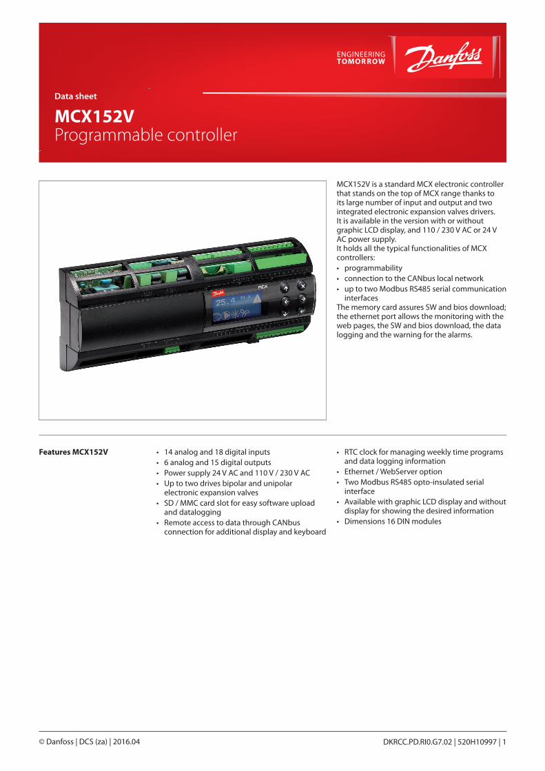
MCX152V is a standard MCX electronic controller that stands on the top of MCX range thanks to its large number of input and output and two integrated electronic expansion valves drivers.It is available in the version with or without graphic LCD display, and 110 / 230 V AC or 24 V AC power supply.It holds all the typical functionalities of MCX controllers:• programmability• connection to the CANbus local network• up to two Modbus RS485 serial communication
interfacesThe memory card assures SW and bios download; the ethernet port allows the monitoring with the web pages, the SW and bios download, the data logging and the warning for the alarms.
Features MCX152V • 14 analog and 18 digital inputs• 6 analog and 15 digital outputs• Power supply 24 V AC and 110 V / 230 V AC• Up to two drives bipolar and unipolar
electronic expansion valves• SD / MMC card slot for easy software upload
and datalogging• Remote access to data through CANbus
connection for additional display and keyboard
• RTC clock for managing weekly time programs and data logging information
• Ethernet / WebServer option• Two Modbus RS485 opto-insulated serial
interface• Available with graphic LCD display and without
display for showing the desired information• Dimensions 16 DIN modules
Data sheet
MCX152V Programmable controller
DKRCC.PD.RI0.G7.02 | 520H10997 | 1© Danfoss | DCS (za) | 2016.04
General features FEATURES DESCRIPTION
Power supply 85 – 265 V AC, 50/60 HzMaximum power consumption: 30 W, 51 V AInsulation between power supply and the extra-low voltage: reinforced
24 V AC ± 15% 50/60 HzMaximum power consumption: 30 W, 47 V AInsulation between power supply and the extra-low voltage: functional
Plastic housing DIN rail mounting complying with EN 60715
Self extinguishing V0 according to IEC 60695-11-10 and glowing/hot wire test at 960 °C according to IEC 60695-2-12
Ball test 125 °C according to IEC 60730-1Leakage current: ≥ 250 V according to IEC 60112
Operating conditions CE: -20T60 / UL: 0T55, 90% RH non-condensing
Storage conditions -30T80, 90% RH non-condensing
Integration In Class I and / or II appliances
Index of protection IP40 only on the front cover
Period of electric stressacross insulating parts
Long
Resistance to heat and fire Category D
Immunity against voltagesurges
Category II
Software class andstructure
Class A
Approvals CE compliance:This product is designed to comply with the following EU standards:• Low voltage guideline: 73/23/EEC• Electromagnetic compatibility EMC: 89/336/EEC and with the following
norms: – EN61000-6-1, EN61000-6-3
(immunity for residential, commercial and light-industrial environments) – EN61000-6-2, EN61000-6-4
(immunity and emission standard for industrial environments) – EN60730
(Automatic electrical controls for household and similar use)
UL approval:• UL file E31024
Data sheet | MCX152V
© Danfoss | DCS (za) | 2016.04 DKRCC.PD.RI0.G7.02 | 520H10997 | 2

Input/output I/O TYPE NUM SPECIFICATIONS
Analoginputs
Max 15 V input voltageDo not connect voltage sources without current limitation (overall 80 mA) to analog inputs while unit is not poweredOpen circuit HW diagnostics available for all analog inputs
0 / 1 V0 / 5 V0 / 10 V
14 AI1, AI2, AI3, AI4, AI5, AI6, AI7, AI8, AI9, AI10, AI11, AI12, AI13, AI14
NTC 14 AI1, AI2, AI3, AI4, AI5, AI6, AI7, AI8, AI9, AI10, AI11, AI12, AI13, AI14NTC temperature probes, default: 10 kΩ at 25 °C
0 / 20 mA4 / 20 mA
8 AI1, AI2, AI3, AI5, AI8, AI9, AI10, AI12
Pt1000 8 AI1, AI2, AI3, AI7, AI8, AI9, AI10, AI14
Differentialinput
2 AI5(-), AI6(+);AI12(-), AI13(+)Differential input, DM Voltage 0...300 mV; CM voltage max 14 V
AuxiliarySupplies
2 15 V+ and 5 V+5 V+ max: 140 mA (total on all outputs)15 V+ max: 200 mA (total on all outputs)
Digitalinput
Voltage freecontacts
16 DI1, DI2(Frequency input) min. pulse time 2.5 msDI3, DI4, DI5, DI6, DI7, DI8, DI9, DI10, DI11, DI12, DI13, DI14, DI15, DI16Min pulse time 25 ms
24 Voptoins
2 DI17, DI18Digital Inputs optoinsulated 24 V AC / 50/60 Hz o 24 V DCRated current: 5 mA
230 V ACoptoins
2 DI17, DI18Inputs optoinsulated, 230 V AC / 50/60 HzBasic insulationRated current: 2 mA at 230 V AC; 1 mA at 110 V ACNOTE: when the 230 V AC DI17H input is used, the corresponding 24 V DI17input is not available anymore; the same for the couple of inputs DI18H and DI18
Analogoutputs
0 / 10 V DC 6 AO1, AO2, AO3, AO4, AO5, AO6Current max: 10 mA
PWM, PPM 2 AO3, AO6• pulse output, synchronous with mains, at modulation of impulse position
(PPM)or modulation of impulse width (PWM): 6.8 V open circuit• pulse output, PWM with range from 20 Hz to 1 kHz: 6.8 V open circuit
Digitaloutput
Relay 15 Concerning the insulation distance there are three groups of relays:• group 1: relays 1 to 8• group 2: relays 9 to 12• group 3: relays 13 to 15Insulation between relays: functionalInsulation between relays of group 1 and 2 and 3: reinforcedInsulation between relays and the extra-low voltage parts: reinforcedC1-NO1 to C12-NO12Normally open contact relays 5 Acharacteristics of each relay:• 5 A 250 V AC for resistive loads - 100.000 cycles• 3 A 250 V AC for inductive load - 100.000 cycles with cos(phi) = 0.4• UL: 1/8 hp, C300 pilot duty, 125 / 250 V AC, 30.000 cyclesC13-NO13 to C15-NO15Normally open contact relays 16 Acharacteristics of each relay:• 7 A 250 V AC for resistive loads - 100.000 cycles• 3.5 A 250 V AC for inductive load - 230.000 cycles with cos(phi) = 0.4• UL: 6 A resistive, 240 V A, 30.000 cycles, 1/2 hp, 470 V A pilot duty, 240 V AC,
30.000 cyclesC1-NO1 to C3-NO3, C13-NO13 to C15-NO15Optionally they can be solid state relayscharacteristics of each relay:• 15-280 Vrms, 1 A• UL: 1 A resistive, 240 V AC, 30.000 cycles
Data sheet | MCX152V
© Danfoss | DCS (za) | 2016.04 DKRCC.PD.RI0.G7.02 | 520H10997 | 3
I/O TYPE NUM SPECIFICATIONS
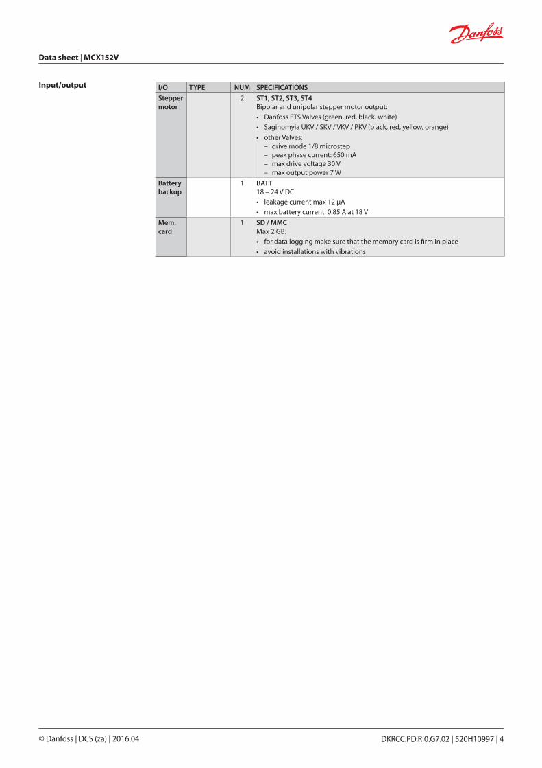
Steppermotor
2 ST1, ST2, ST3, ST4Bipolar and unipolar stepper motor output:• Danfoss ETS Valves (green, red, black, white)• Saginomyia UKV / SKV / VKV / PKV (black, red, yellow, orange)
• other Valves: – drive mode 1/8 microstep – peak phase current: 650 mA – max drive voltage 30 V – max output power 7 W
Batterybackup
1 BATT18 – 24 V DC:• leakage current max 12 μA• max battery current: 0.85 A at 18 V
Mem.card
1 SD / MMCMax 2 GB:• for data logging make sure that the memory card is firm in place• avoid installations with vibrations
Input/output
Data sheet | MCX152V
© Danfoss | DCS (za) | 2016.04 DKRCC.PD.RI0.G7.02 | 520H10997 | 4

Connection diagram
*NOTE: connection has to be made on the first and last local network units, make the connection as close as possible to the connector
MCX
152V
- TO
P
MCX
152V
- BO
TTO
M
whi
tebl
ack
red
gree
n
STEPPERMOTOR 2
RS485-1
SD/MMC
ST2
4
ST2
3
ST2
2
ST2
1
COM
1
D1
+
D1
-
RS485-2
COM
2
D2
+
D2
-
DIGITAL INPUT 18 DIGITAL OUTPUT 9-12 DIGITAL OUTPUT 13-15STEPPER BACKUP
COM
+ BA
TT
DIGITAL INPUT 1-8 DIGITAL INPUT 9-16POWERSUPPLY
L N
MEMORY CARD ANALOG OUTPUT 1-6 ANALOG INPUT 1-7
CAN CAN-RJ ETHERNET DIGITAL INPUT 17
ANALOG INPUT 8-14
RS48
5(M
odbu
s)
supervisorynetwork
CAN
bus
CAN
buslo
cal n
etw
ork
COM
CAN
L
CAN
H
R120
COM
17
DI 1
7
DIGITAL OUTPUT 6-8
NO
8 C 8
NO
7 C 7
NO
6 C 6
DIGITAL OUTPUT 1-5
NO
3 C 3
NO
2 C 2
NO
5 C 5
NO
4 C 4
NO
1 C 1
CAN
-RJ
CAN
bus
ETH
supervisorynetworkMMIGRS
N
L
N
L
N
L
5 A
AO 1
AO 2
AO 3
5 A
5 A
5 A
5 A
5 A
5 A
5 A
whi
tebl
ack
red
gree
n
oran
geye
llow
Red
blac
k
oran
geye
llow
Red
blac
k
STEPPERMOTOR 1
ST1
4
ST1
3
ST1
2
ST1
1
PWM
-PPM
-0/1
0 V
UN
IVER
SAL
UN
IVER
SAL
UN
IVER
SAL
PRO
GRA
MM
ABL
E
PRO
GRA
MM
ABL
E
PRO
GRA
MM
ABL
E
0/10
V
0/10
V
AO 4
AO 5
AO 6
PWM
-PPM
-0/1
0 V
0/10
V
0/10
V
AO 6
AO 5
AO 4
COM
AO 3
AO 2
AO 1
COM
NTC, Pt1000,ON/OFF, 0/1 V,0/5 V, 0/10 V,
0/20 mA, 4/20 mA
+
18 V
BATTBACKUP
UN
IVER
SAL
UN
IVER
SAL
UN
IVER
SAL
PRO
GRA
MM
ABL
E
Out
onl
y ba
ckup
bat
tery
NTC, Pt1000,ON/OFF, 0/1 V,0/5 V, 0/10 V,
0/20 mA, 4/20 mA
PRO
GRA
MM
ABL
E
PRO
GRA
MM
ABL
E
PRO
GRA
MM
ABL
E
DI 1
7H
7 A
7 A
7 A
7 A
7 A
7 A
5 A
5 A
5 A
5 A
15V+
COM
DI 9
DI 1
0
DI 1
1
DI 1
2
COM
DI 1
3
DI 1
4
DI 1
5
DI 1
6
COM
DI 1
DI 2
DI 3
DI 4
COM
DI 5
DI 6
DI 7
DI 8
DI 1
8H
DI 1
8
COM
18
C 9
NO
9
C 10
NO
10
C 11
NO
11
C 12
NO
12
C 13
C 13
NO
13
NC
13
C 14
NO
14
NC
14
C 15
NO
15
NC
15
To th
e A
I
To th
e A
I
To th
e A
I
To th
e A
I
COM
COM
15V+AI 7
AI 6
AI 5
5V+
AI 4
AI 3
AI 2
AI 1
COM
COM
15V+
AI 1
4
AI 1
3
AI 1
2
5V+
AI 1
1
AI 1
0
AI 9
AI 8
PRO
GRA
MM
ABL
E
ETS/KWSvalves
Saginomyavalves
Dan
foss
80G
8043
.01
MCX
152V
- TO
P
MCX
152V
- BO
TTO
M
whi
tebl
ack
red
gree
n
STEPPERMOTOR 2
RS485-1
SD/MMC
ST2
4
ST2
3
ST2
2
ST2
1
COM
1
D1
+
D1
-
RS485-2
COM
2
D2
+
D2
-
DIGITAL INPUT 18 DIGITAL OUTPUT 9-12 DIGITAL OUTPUT 13-15STEPPER BACKUP
COM
+ BA
TT
DIGITAL INPUT 1-8 DIGITAL INPUT 9-16POWERSUPPLY
L N
MEMORY CARD ANALOG OUTPUT 1-6 ANALOG INPUT 1-7
CAN CAN-RJ ETHERNET DIGITAL INPUT 17
ANALOG INPUT 8-14
RS48
5(M
odbu
s)
supervisorynetwork
CAN
bus
CAN
buslo
cal n
etw
ork
COM
CAN
L
CAN
H
R120
COM
17
DI 1
7
DIGITAL OUTPUT 6-8
NO
8 C 8
NO
7 C 7
NO
6 C 6
DIGITAL OUTPUT 1-5
NO
3 C 3
NO
2 C 2
NO
5 C 5
NO
4 C 4
NO
1 C 1
CAN
-RJ
CAN
bus
ETH
supervisorynetworkMMIGRS
N
L
N
L
N
L
5 A
AO 1
AO 2
AO 3
5 A
5 A
5 A
5 A
5 A
5 A
5 A
whi
tebl
ack
red
gree
n
oran
geye
llow
Red
blac
k
oran
geye
llow
Red
blac
k
STEPPERMOTOR 1
ST1
4
ST1
3
ST1
2
ST1
1
PWM
-PPM
-0/1
0 V
UN
IVER
SAL
UN
IVER
SAL
UN
IVER
SAL
PRO
GRA
MM
ABL
E
PRO
GRA
MM
ABL
E
PRO
GRA
MM
ABL
E
0/10
V
0/10
V
AO 4
AO 5
AO 6
PWM
-PPM
-0/1
0 V
0/10
V
0/10
V
AO 6
AO 5
AO 4
COM
AO 3
AO 2
AO 1
COM
NTC, Pt1000,ON/OFF, 0/1 V,0/5 V, 0/10 V,
0/20 mA, 4/20 mA
+
18 V
BATTBACKUP
UN
IVER
SAL
UN
IVER
SAL
UN
IVER
SAL
PRO
GRA
MM
ABL
E
Out
onl
y ba
ckup
bat
tery
NTC, Pt1000,ON/OFF, 0/1 V,0/5 V, 0/10 V,
0/20 mA, 4/20 mA
PRO
GRA
MM
ABL
E
PRO
GRA
MM
ABL
E
PRO
GRA
MM
ABL
E
DI 1
7H
7 A
7 A
7 A
7 A
7 A
7 A
5 A
5 A
5 A
5 A
15V+
COM
DI 9
DI 1
0
DI 1
1
DI 1
2
COM
DI 1
3
DI 1
4
DI 1
5
DI 1
6
COM
DI 1
DI 2
DI 3
DI 4
COM
DI 5
DI 6
DI 7
DI 8
DI 1
8H
DI 1
8
COM
18
C 9
NO
9
C 10
NO
10
C 11
NO
11
C 12
NO
12
C 13
C 13
NO
13
NC
13
C 14
NO
14
NC
14
C 15
NO
15
NC
15
To th
e A
I
To th
e A
I
To th
e A
I
To th
e A
I
COM
COM
15V+AI 7
AI 6
AI 5
5V+
AI 4
AI 3
AI 2
AI 1
COM
COM
15V+
AI 1
4
AI 1
3
AI 1
2
5V+
AI 1
1
AI 1
0
AI 9
AI 8
PRO
GRA
MM
ABL
E
ETS/KWSvalves
Saginomyavalves
Dan
foss
80G
8043
.01
Data sheet | MCX152V
© Danfoss | DCS (za) | 2016.04 DKRCC.PD.RI0.G7.02 | 520H10997 | 5
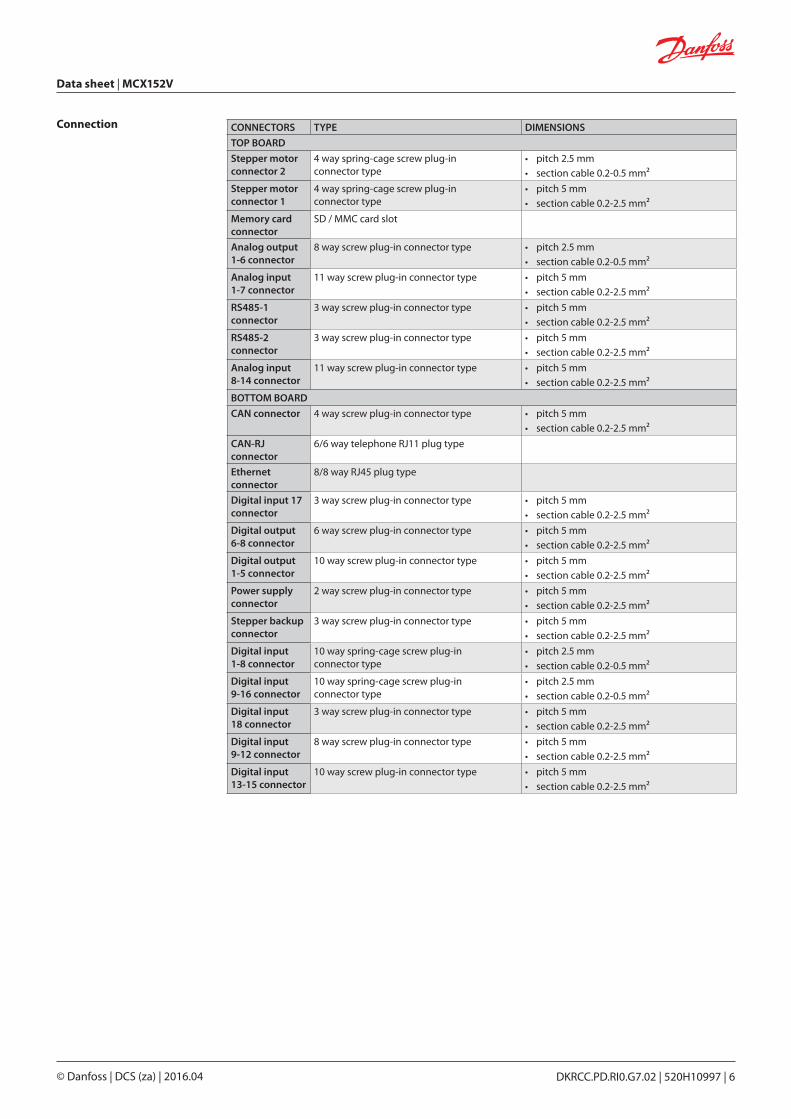
Connection CONNECTORS TYPE DIMENSIONS
TOP BOARD
Stepper motorconnector 2
4 way spring-cage screw plug-inconnector type
• pitch 2.5 mm• section cable 0.2-0.5 mm²
Stepper motorconnector 1
4 way spring-cage screw plug-inconnector type
• pitch 5 mm• section cable 0.2-2.5 mm²
Memory cardconnector
SD / MMC card slot
Analog output1-6 connector
8 way screw plug-in connector type • pitch 2.5 mm• section cable 0.2-0.5 mm²
Analog input1-7 connector
11 way screw plug-in connector type • pitch 5 mm• section cable 0.2-2.5 mm²
RS485-1connector
3 way screw plug-in connector type • pitch 5 mm• section cable 0.2-2.5 mm²
RS485-2connector
3 way screw plug-in connector type • pitch 5 mm• section cable 0.2-2.5 mm²
Analog input8-14 connector
11 way screw plug-in connector type • pitch 5 mm• section cable 0.2-2.5 mm²
BOTTOM BOARD
CAN connector 4 way screw plug-in connector type • pitch 5 mm• section cable 0.2-2.5 mm²
CAN-RJconnector
6/6 way telephone RJ11 plug type
Ethernetconnector
8/8 way RJ45 plug type
Digital input 17connector
3 way screw plug-in connector type • pitch 5 mm• section cable 0.2-2.5 mm²
Digital output6-8 connector
6 way screw plug-in connector type • pitch 5 mm• section cable 0.2-2.5 mm²
Digital output1-5 connector
10 way screw plug-in connector type • pitch 5 mm• section cable 0.2-2.5 mm²
Power supplyconnector
2 way screw plug-in connector type • pitch 5 mm• section cable 0.2-2.5 mm²
Stepper backupconnector
3 way screw plug-in connector type • pitch 5 mm• section cable 0.2-2.5 mm²
Digital input1-8 connector
10 way spring-cage screw plug-inconnector type
• pitch 2.5 mm• section cable 0.2-0.5 mm²
Digital input9-16 connector
10 way spring-cage screw plug-inconnector type
• pitch 2.5 mm• section cable 0.2-0.5 mm²
Digital input18 connector
3 way screw plug-in connector type • pitch 5 mm• section cable 0.2-2.5 mm²
Digital input9-12 connector
8 way screw plug-in connector type • pitch 5 mm• section cable 0.2-2.5 mm²
Digital input13-15 connector
10 way screw plug-in connector type • pitch 5 mm• section cable 0.2-2.5 mm²
Data sheet | MCX152V
© Danfoss | DCS (za) | 2016.04 DKRCC.PD.RI0.G7.02 | 520H10997 | 6
Danfoss can accept no responsibility for possible errors in catalogues, brochures and other printed material. Danfoss reserves the right to alter its products without notice. This also applies to products already on order provided that such alterations can be made without subsequential changes being necessary eady agreed.All trademarks in this material are property of the respective companies. Danfoss and the Danfoss logotype are trademarks of Danfoss A/S. All rights reserved.
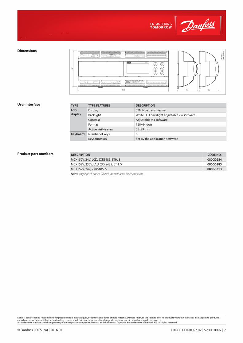
Product part numbers
User interface
DESCRIPTION CODE NO.
MCX152V, 24V, LCD, 2XRS485, ETH, S 080G0284
MCX152V, 230V, LCD, 2XRS485, ETH, S 080G0285
MCX152V, 24V, 2XRS485, S 080G0313
Note: single pack codes (S) include standard kit connectors
TYPE TYPE FEATURES DESCRIPTION
LCDdisplay
Display STN blue transmissive
Backlight White LED backlight adjustable via software
Contrast Adjustable via software
Format 128x64 dots
Active visible area 58x29 mm
Keyboard Number of keys 6
Keys function Set by the application software
Dimensions
110
280 6063
Dan
foss
80G
8044
.01
© Danfoss | DCS (za) | 2016.04 DKRCC.PD.RI0.G7.02 | 520H10997 | 7