![DATA SHEET AAT312552ebad10ee97eea25d5e-d7d40819259e7d3022d9ad53e3694148.r84… · 2013. 3. 28. · 1 AAT3125 DATA SHEET USB OTG 5V Charge Pump Skyworks Solutions, Inc. • Phone [781]](https://static.fdocuments.in/doc/165x107/6094d8572522246ef82846ec/data-sheet-aat312552ebad10ee97eea25d5e-d7d40819259e7d3022d9ad53e3694148r84-2013.jpg)
DATA SHEET AAT3120 - Skyworks Solutions · • ul , 202 Typical Application C IN 1µF V BATTERY C...
13
AAT3120 DATA SHEET Three-Channel Charge Pump for White LED Applications 1 Skyworks Solutions, Inc. • Phone [781] 376-3000 • Fax [781] 376-3100 • [email protected] • www.skyworksinc.com 202130A • Skyworks Proprietary Information • Products and Product Information are Subject to Change Without Notice. • July 4, 2012 Typical Application C IN 1μF V BATTERY C OUT 1μF EN/SET C1 1μF C2 1μF D3 VIN VOUT C1+ C1- C2+ C2- D1 D2 D3 EN/SET GND AAT3120 D2 D1 General Description The AAT3120 is a low noise, constant frequency charge pump DC/DC converter that uses fractional (1.5X) con- version to improve efficiency for white LED applications. The device can be used to produce eight current levels up to 20mA per channel for up to three channels. 1X load switch mode is also built-in to improve efficiency at low current settings. Low external parts count (two 1µF fly- ing capacitors and two small 1µF capacitors at V IN and OUT) makes the AAT3120 ideally suited for small bat- tery-powered applications. Skyworks' S 2 Cwire™ (Simple Serial Control™) serial digital input is used to enable, disable, and set current for each LED at eight different levels. The AAT3120 has a thermal management system to pro- tect the device in the event of a short-circuit condition at the output pin. Built-in soft-start circuitry prevents excessive inrush current during start-up. A high charge pump switching frequency enables the use of very small external capacitors. A low current shutdown feature dis- connects the load from V IN and reduces quiescent current to less than 1µA. The AAT3120 is available in the very small Pb-free 12-pin TSOPJW package. Features • V IN Range: 2.7V to 5.5V • Fractional Charge Pump Mode • Drives Low-V F and High-V F Type LEDs • Up to Three LED Outputs ▪ Single Wire Programming ▪ Eight Regulated Current Settings ▪ Max 20mA per Channel • Low Noise Constant Frequency Operation • No Inductors • 1MHz Switching Frequency • Small Application Circuit • Automatic Soft-Start • I Q <1µA in Shutdown • 12-Pin TSOPJW Package Applications • Color (RGB) Lighting • Programmable Current Source • White LED Backlighting • White Photo Flash for DSCs
Transcript of DATA SHEET AAT3120 - Skyworks Solutions · • ul , 202 Typical Application C IN 1µF V BATTERY C...

AAT3120DATA SHEET
Three-Channel Charge Pump for White LED Applications
1Skyworks Solutions, Inc. • Phone [781] 376-3000 • Fax [781] 376-3100 • [email protected] • www.skyworksinc.com
202130A • Skyworks Proprietary Information • Products and Product Information are Subject to Change Without Notice. • July 4, 2012
Typical Application
CIN
1µF
VBATTERY COUT
1µF
EN/SET
C1
1µF
C2
1µF
D3
VIN
VOUT
C1+
C1-
C2+
C2-
D1
D2
D3EN/SET
GND
AAT3120
D2 D1
General DescriptionThe AAT3120 is a low noise, constant frequency charge pump DC/DC converter that uses fractional (1.5X) con-version to improve efficiency for white LED applications. The device can be used to produce eight current levels up to 20mA per channel for up to three channels. 1X load switch mode is also built-in to improve efficiency at low current settings. Low external parts count (two 1µF fly-ing capacitors and two small 1µF capacitors at VIN and OUT) makes the AAT3120 ideally suited for small bat-tery-powered applications.
Skyworks' S2Cwire™ (Simple Serial Control™) serial digital input is used to enable, disable, and set current for each LED at eight different levels.
The AAT3120 has a thermal management system to pro-tect the device in the event of a short-circuit condition at the output pin. Built-in soft-start circuitry prevents excessive inrush current during start-up. A high charge pump switching frequency enables the use of very small external capacitors. A low current shutdown feature dis-connects the load from VIN and reduces quiescent current to less than 1µA. The AAT3120 is available in the very small Pb-free 12-pin TSOPJW package.
Features• VIN Range: 2.7V to 5.5V• Fractional Charge Pump Mode• Drives Low-VF and High-VF Type LEDs• Up to Three LED Outputs▪ Single Wire Programming▪ Eight Regulated Current Settings▪ Max 20mA per Channel
• Low Noise Constant Frequency Operation• No Inductors• 1MHz Switching Frequency• Small Application Circuit• Automatic Soft-Start• IQ <1µA in Shutdown• 12-Pin TSOPJW Package
Applications• Color(RGB)Lighting• ProgrammableCurrentSource• WhiteLEDBacklighting• WhitePhotoFlashforDSCs

AAT3120DATA SHEET
Three-Channel Charge Pump for White LED Applications
2Skyworks Solutions, Inc. • Phone [781] 376-3000 • Fax [781] 376-3100 • [email protected] • www.skyworksinc.com
202130A • Skyworks Proprietary Information • Products and Product Information are Subject to Change Without Notice. • July 4, 2012
Pin Descriptions
Pin # Symbol Function1 C2+ Flying capacitor 2 positive terminal. Connect a 1µF capacitor between C2+ and C2-.2 OUT Charge pump output. Requires 1µF capacitor connected between this pin and ground.3 C1- Flying capacitor 1 negative terminal.4 C1+ Flying capacitor 1 positive terminal. Connect a 1µF capacitor between C1+ and C1-.5 N/C No connection.6 D3 Current source output #3.7 D2 Current source output #2.8 D1 Current source output #1.9 EN/SET Control pin.10 IN Input power supply. Requires 1µF capacitor connected between this pin and ground.11 GND Ground.12 C2- Flying capacitor 2 negative terminal.
Pin Configuration
TSOPJW-12 (Top View)
1
2
3
4
5
6
12
11
10
9
8
7
C2+
OUT
C1-
C1+
N/C
D3
C2-
GND
IN
EN/SET
D1
D2
AAT3120DATA SHEET
Three-Channel Charge Pump for White LED Applications
3Skyworks Solutions, Inc. • Phone [781] 376-3000 • Fax [781] 376-3100 • [email protected] • www.skyworksinc.com
202130A • Skyworks Proprietary Information • Products and Product Information are Subject to Change Without Notice. • July 4, 2012
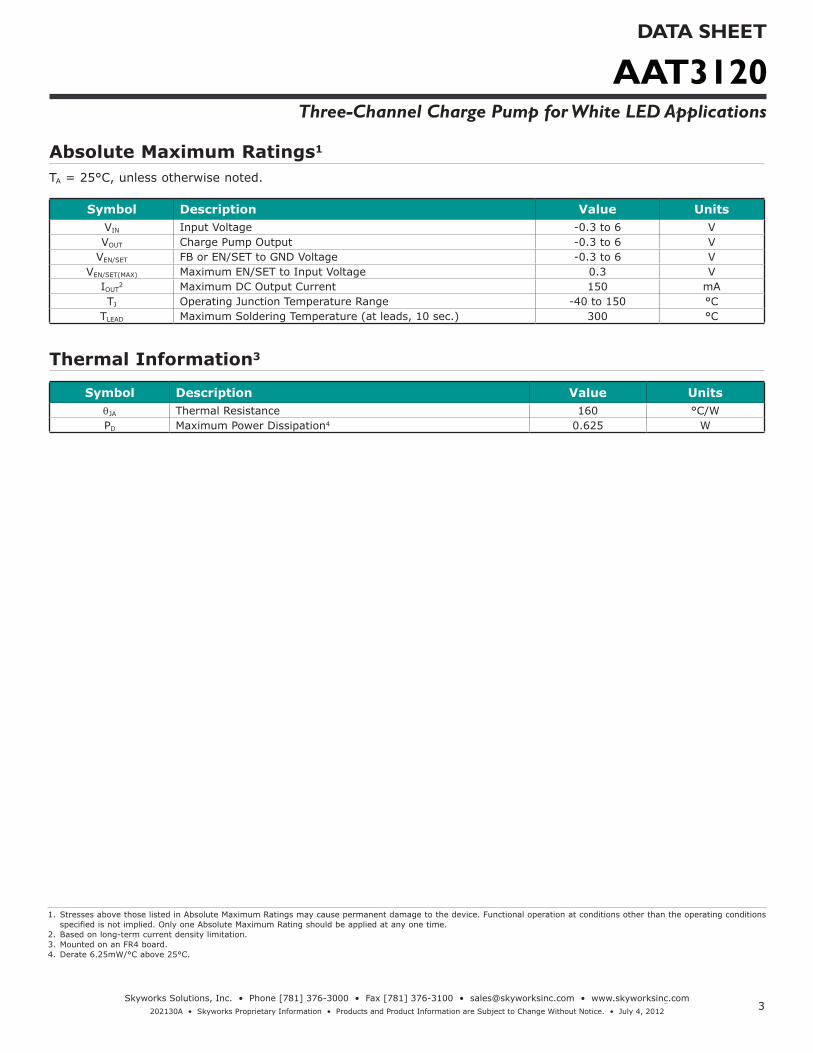
1. Stresses above those listed in Absolute Maximum Ratings may cause permanent damage to the device. Functional operation at conditions other than the operating conditions specified is not implied. Only one Absolute Maximum Rating should be applied at any one time.
2. Based on long-term current density limitation.3. Mounted on an FR4 board.4. Derate 6.25mW/°C above 25°C.
Absolute Maximum Ratings1
TA = 25°C, unless otherwise noted.
Symbol Description Value UnitsVIN Input Voltage -0.3 to 6 VVOUT Charge Pump Output -0.3 to 6 V
VEN/SET FBorEN/SETtoGNDVoltage -0.3 to 6 VVEN/SET(MAX) Maximum EN/SET to Input Voltage 0.3 V
IOUT2 Maximum DC Output Current 150 mA
TJ Operating Junction Temperature Range -40 to 150 °CTLEAD Maximum Soldering Temperature (at leads, 10 sec.) 300 °C
Thermal Information3
Symbol Description Value UnitsqJA Thermal Resistance 160 °C/WPD Maximum Power Dissipation4 0.625 W

AAT3120DATA SHEET
Three-Channel Charge Pump for White LED Applications
4Skyworks Solutions, Inc. • Phone [781] 376-3000 • Fax [781] 376-3100 • [email protected] • www.skyworksinc.com
202130A • Skyworks Proprietary Information • Products and Product Information are Subject to Change Without Notice. • July 4, 2012
1. The AAT3120 is guaranteed to meet performance specifications over the -40°C to +85°C operating temperature range and is assured by design, characterization, and correla-tion with statistical process controls.
Electrical Characteristics1
CIN = COUT = C1 = C2 = 1.0µF; TA = -40°C to +85°C, unless otherwise noted. Typical values are TA = 25°C, VIN = 3.5V.
Symbol Description Conditions Min Typ Max UnitsInput Power Supply
VIN Operation Range 2.7 5.5 VICC Operating Current 3.0V≤VIN≤5.5V,Active,NoLoadCurrent 1.8 3.0 mA
ISHDN Shutdown Current EN = 0 1.0 µAIDX Output Current 3.0≤VIN≤5.5 18 20 22 mA
I(D-Match)Current Matching Between Any Two Outputs VD1:D3 = 3.6, VIN = 3.5V 0.5 %
Charge Pump SectionTSS Soft-Start Time 200 µsFCLK Clock Frequency 1000 kHz
EN/SETVEN(L) Enable Threshold Low 2.7V≤VIN≤5.5V 0.4 VVEN(H) Enable Threshold High 2.7V≤VIN≤5.5V 1.4 V
TEN/SET LO EN/SET Low Time 0.3 75 µsTEN/SET HI Minimum EN/SET High Time 50 ns
TOFF EN/SET Off Timeout 500 µsInput Current EN/SET Input Leakage -1 1 µA

AAT3120DATA SHEET
Three-Channel Charge Pump for White LED Applications
5Skyworks Solutions, Inc. • Phone [781] 376-3000 • Fax [781] 376-3100 • [email protected] • www.skyworksinc.com
202130A • Skyworks Proprietary Information • Products and Product Information are Subject to Change Without Notice. • July 4, 2012
Typical Characteristics
Turn-On to Full-Scale Load Switch
Time (100µs/div)
ENSET(2V/div)
CP(2V/div)
VDIODE(2V/div)
IIN(200mA/div)
Turn-On to Full-Scale Charge Pump
Time (100µs/div)
ENSET(2V/div)
CP(2V/div)
VDIODE(2V/div)
IIN(200mA/div)
Turn-Off from Full-Scale Charge Pump
Time (400µs/div)
ENSET(2V/div)
VDIODE(2V/div)
IIN(100mA/div)
IDIODE vs. Input Voltage(3x20mA)
Input Voltage (V)
I DIO
DE (
mA
)
50
53
56
59
62
65
2.7 2.9 3.1 3.3 3.5 3.7 3.9 4.1 4.3 4.5 4.7 4.9 5.1
VF = 3.0V VF = 3.2V
VF = 3.4V
IDIODE vs. Input Voltage(3x8.3mA)
Input Voltage (V)
I DIO
DE (
mA
)
15
18
21
24
27
30
2.7 2.9 3.1 3.3 3.5 3.7 3.9 4.1 4.3 4.5 4.7 4.9 5.1
VF = 3.0V VF = 3.2V
VF = 3.4V
AAT3120DATA SHEET
Three-Channel Charge Pump for White LED Applications
6Skyworks Solutions, Inc. • Phone [781] 376-3000 • Fax [781] 376-3100 • [email protected] • www.skyworksinc.com
202130A • Skyworks Proprietary Information • Products and Product Information are Subject to Change Without Notice. • July 4, 2012
Typical Characteristics
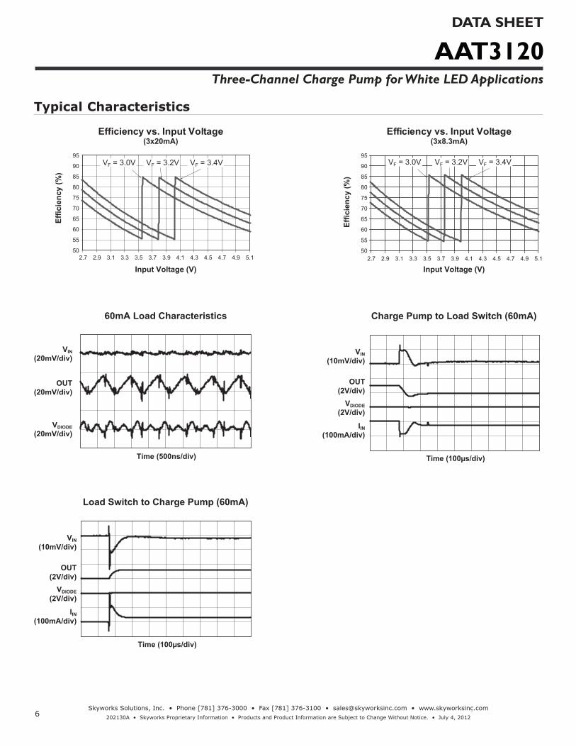
Efficiency vs. Input Voltage(3x20mA)
Input Voltage (V)
Effic
ienc
y (%
)
50
55
60
65
70
75
80
85
90
95
2.7 2.9 3.1 3.3 3.5 3.7 3.9 4.1 4.3 4.5 4.7 4.9 5.1
VF = 3.0V VF = 3.2V VF = 3.4V
Efficiency vs. Input Voltage(3x8.3mA)
Input Voltage (V)
Effic
ienc
y (%
)
50
55
60
65
70
75
80
85
90
95
2.7 2.9 3.1 3.3 3.5 3.7 3.9 4.1 4.3 4.5 4.7 4.9 5.1
VF = 3.0V VF = 3.2V VF = 3.4V
60mA Load Characteristics
Time (500ns/div)
OUT(20mV/div)
VDIODE(20mV/div)
VIN(20mV/div)
Charge Pump to Load Switch (60mA)
Time (100µs/div)
OUT(2V/div)
VDIODE(2V/div)
VIN(10mV/div)
IIN(100mA/div)
Load Switch to Charge Pump (60mA)
Time (100µs/div)
OUT(2V/div)
VDIODE(2V/div)
VIN(10mV/div)
IIN(100mA/div)
AAT3120DATA SHEET
Three-Channel Charge Pump for White LED Applications
7Skyworks Solutions, Inc. • Phone [781] 376-3000 • Fax [781] 376-3100 • [email protected] • www.skyworksinc.com
202130A • Skyworks Proprietary Information • Products and Product Information are Subject to Change Without Notice. • July 4, 2012
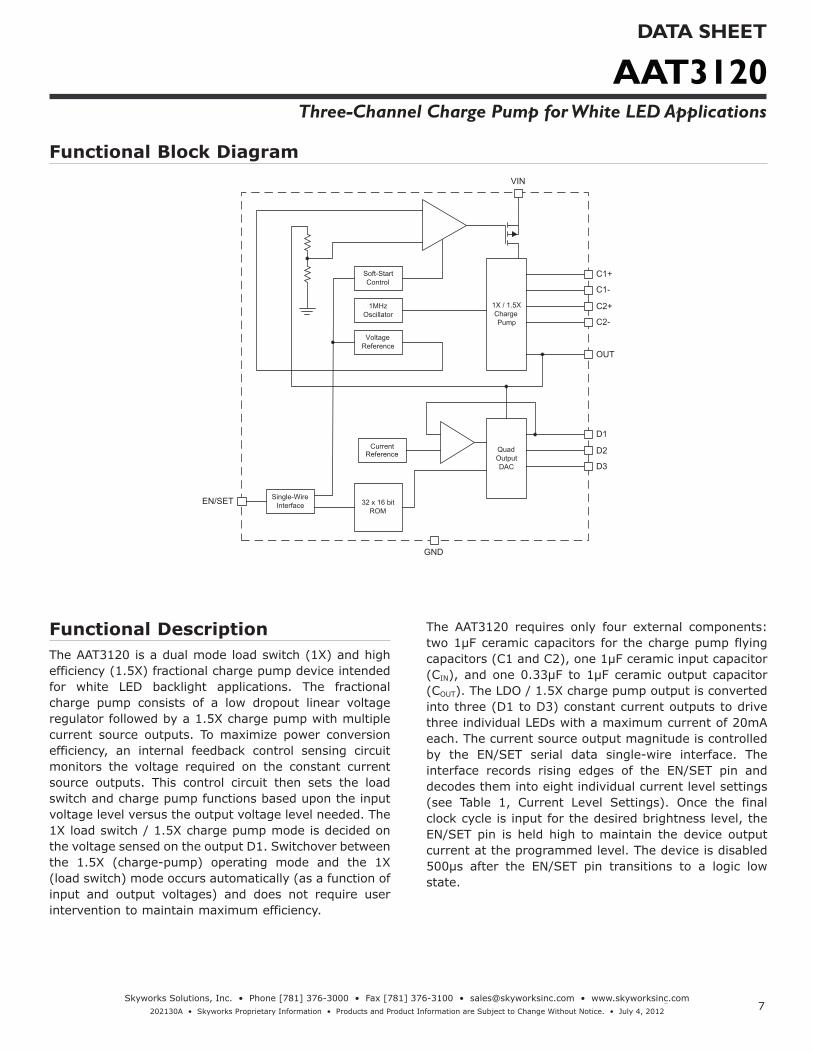
Functional DescriptionThe AAT3120 is a dual mode load switch (1X) and high efficiency (1.5X) fractional charge pump device intended for white LED backlight applications. The fractional charge pump consists of a low dropout linear voltage regulator followed by a 1.5X charge pump with multiple current source outputs. To maximize power conversion efficiency, an internal feedback control sensing circuit monitors the voltage required on the constant current source outputs. This control circuit then sets the load switch and charge pump functions based upon the input voltage level versus the output voltage level needed. The 1X load switch / 1.5X charge pump mode is decided on the voltage sensed on the output D1. Switchover between the 1.5X (charge-pump) operating mode and the 1X (load switch) mode occurs automatically (as a function of input and output voltages) and does not require user intervention to maintain maximum efficiency.
The AAT3120 requires only four external components: two 1µF ceramic capacitors for the charge pump flying capacitors (C1 and C2), one 1µF ceramic input capacitor (CIN), and one 0.33µF to 1µF ceramic output capacitor (COUT). The LDO / 1.5X charge pump output is converted into three (D1 to D3) constant current outputs to drive three individual LEDs with a maximum current of 20mA each. The current source output magnitude is controlled by the EN/SET serial data single-wire interface. The interface records rising edges of the EN/SET pin and decodes them into eight individual current level settings (see Table 1, Current Level Settings). Once the final clock cycle is input for the desired brightness level, the EN/SET pin is held high to maintain the device output current at the programmed level. The device is disabled 500µs after the EN/SET pin transitions to a logic low state.
Functional Block Diagram
1X / 1.5X
Charge
Pump
Soft-Start
Control
1MHz
Oscillator
Voltage
Reference
Quad
Output
DAC
Current
Reference
Single-Wire
Interface32 x 16 bit
ROM
C1+
C1-
C2+
C2-
OUT
D1
D2
D3
GND
EN/SET
VIN
AAT3120DATA SHEET
Three-Channel Charge Pump for White LED Applications
8Skyworks Solutions, Inc. • Phone [781] 376-3000 • Fax [781] 376-3100 • [email protected] • www.skyworksinc.com
202130A • Skyworks Proprietary Information • Products and Product Information are Subject to Change Without Notice. • July 4, 2012
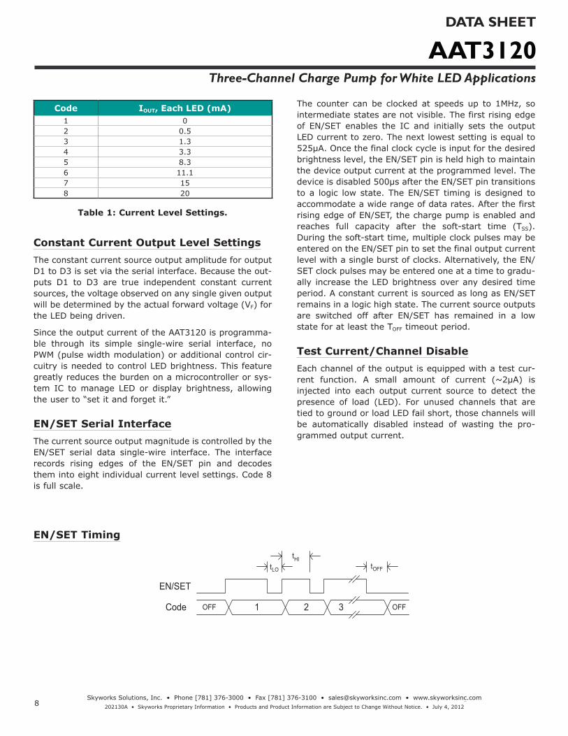
EN/SET Timing
EN/SET
Code 1 2 3 OFFOFF
tHItLO tOFF
Code IOUT, Each LED (mA)1 02 0.53 1.34 3.35 8.36 11.17 158 20
Table 1: Current Level Settings.
Constant Current Output Level SettingsThe constant current source output amplitude for output D1 to D3 is set via the serial interface. Because the out-puts D1 to D3 are true independent constant current sources, the voltage observed on any single given output will be determined by the actual forward voltage (VF) for the LED being driven.
Since the output current of the AAT3120 is programma-ble through its simple single-wire serial interface, no PWM (pulse width modulation) or additional control cir-cuitry is needed to control LED brightness. This feature greatly reduces the burden on a microcontroller or sys-tem IC to manage LED or display brightness, allowing the user to “set it and forget it.”
EN/SET Serial InterfaceThe current source output magnitude is controlled by the EN/SET serial data single-wire interface. The interface records rising edges of the EN/SET pin and decodes them into eight individual current level settings. Code 8 is full scale.
The counter can be clocked at speeds up to 1MHz, so intermediate states are not visible. The first rising edge of EN/SET enables the IC and initially sets the output LED current to zero. The next lowest setting is equal to 525µA. Once the final clock cycle is input for the desired brightness level, the EN/SET pin is held high to maintain the device output current at the programmed level. The device is disabled 500µs after the EN/SET pin transitions to a logic low state. The EN/SET timing is designed to accommodate a wide range of data rates. After the first rising edge of EN/SET, the charge pump is enabled and reaches full capacity after the soft-start time (TSS). During the soft-start time, multiple clock pulses may be entered on the EN/SET pin to set the final output current level with a single burst of clocks. Alternatively, the EN/SET clock pulses may be entered one at a time to gradu-ally increase the LED brightness over any desired time period. A constant current is sourced as long as EN/SET remains in a logic high state. The current source outputs are switched off after EN/SET has remained in a low state for at least the TOFF timeout period.
Test Current/Channel DisableEach channel of the output is equipped with a test cur-rent function. A small amount of current (~2µA) is injected into each output current source to detect the presence of load (LED). For unused channels that are tied to ground or load LED fail short, those channels will be automatically disabled instead of wasting the pro-grammed output current.
AAT3120DATA SHEET
Three-Channel Charge Pump for White LED Applications
9Skyworks Solutions, Inc. • Phone [781] 376-3000 • Fax [781] 376-3100 • [email protected] • www.skyworksinc.com
202130A • Skyworks Proprietary Information • Products and Product Information are Subject to Change Without Notice. • July 4, 2012
Applications Information
LED SelectionThe AAT3120 is specifically intended for driving white LEDs. However, the device design will allow the AAT3120 to drive most types of LEDs with forward voltage speci-fications ranging from 2.0V to 4.3V. LED applications may include main and sub-LCD display backlighting, camera photo-flash applications, color (RGB) LEDs,infrared (IR) diodes for remotes, and other loads bene-fiting from a controlled output current generated from a varying input voltage. Since the D1 to D3 output current sources are matched with negligible voltage depen-dence, the LED brightness will be matched regardless of the specific LED forward voltage (VF) levels.
In some instances (e.g., in high-luminous-output appli-cations such as photo-flash) it may be necessary to drive high-VF type LEDs. The low-dropout current-sources in the AAT3120 make it capable of driving LEDs with for-ward voltages as high as 4.3V at full current from an input supply as low as 3.0V. Outputs can be paralleled to drive high current LEDs without complication.
Device Switching Noise PerformanceThe AAT3120 operates at a fixed frequency of approxi-mately 1MHz to control noise and limit harmonics that can interfere with the RF operation of cellular telephone handsets or other communication devices. Back-injected noise appearing on the input pin of the charge pump is 20mV peak-to-peak, typically ten times less than induc-tor-based DC/DC boost converter white LED backlight solutions. The AAT3120 soft-start feature prevents noise transient effects associated with in-rush currents during start up of the charge pump circuit.
Power Efficiency and Device EvaluationThe charge pump efficiency discussion in the following sections only accounts for efficiency of the charge pump section itself. Due to the unique circuit architecture and design of the AAT3120, it is very difficult to measure efficiency in terms of a percent value comparing input power over output power.
Since the AAT3120 outputs are pure constant current sources and typically drive individual loads, it is difficult to measure the output voltage for a given output (D1 to D3) to derive an overall output power measurement. For
any given application, white LED forward voltage levels can differ, yet the output drive current will be maintained as a constant. This makes quantifying output power a difficult task when taken in the context of comparing to other white LED driver circuit topologies. A better way to quantify total device efficiency is to observe the total input power to the device for a given LED current drive level. The best white LED driver for a given application should be based on trade-offs of size, external compo-nents count, reliability, operating range, and total ener-gy usage...not just % efficiency.
The AAT3120 efficiency may be quantified under very specific conditions and is dependent upon the input volt-age versus the output voltage seen across the loads applied to outputs D1 through D3 for a given constant current setting. Depending upon the case of VIN being greater than the specific voltage seen across the load on D1, the device will operate in “load switch” mode. If the voltage seen on the constant current source output is less than VIN, then the device will operate in 1.5X charge pump mode. Each of these two modes will yield different efficiency values. One should refer to the following two sections for explanations of each operational mode.
Load Switch Mode EfficiencyThe AAT3120 load switch mode is operational at all times. It functions alone to enhance device power con-version efficiency when the condition exists where VIN is greater than the voltages at the constant current source outputs. When in “load switch” mode, the voltage con-version efficiency is defined as output power divided by input power:
η = POUT
PIN
The expression to define the ideal efficiency (h) can be rewritten as:
η = POUT = VOUT ∙ IOUT = VOUTPIN VIN ∙ IOUT VIN
-or-
η(%) = 100VOUT
VIN
AAT3120DATA SHEET
Three-Channel Charge Pump for White LED Applications
10Skyworks Solutions, Inc. • Phone [781] 376-3000 • Fax [781] 376-3100 • [email protected] • www.skyworksinc.com
202130A • Skyworks Proprietary Information • Products and Product Information are Subject to Change Without Notice. • July 4, 2012
Charge Pump Section EfficiencyThe AAT3120 contains a fractional charge pump which will boost the input supply voltage in the event where VIN is less than the voltage required on the constant current source outputs. The efficiency (h) can be simply defined as a linear voltage regulator with an effective output voltage that is equal to one and one half times the input voltage. Efficiency (h) for an ideal 1.5X charge pump can typically be expressed as the output power divided by the input power.
η = POUT
PIN
In addition, with an ideal 1.5X charge pump, the output current may be expressed as 2/3 of the input current. The expression to define the ideal efficiency (h) can be rewritten as:
η = POUT = VOUT ∙ IOUT = VOUTPIN VIN ∙ 1.5IOUT 1.5VIN
-or-
η(%) = 100VOUT
1.5VIN
For a charge pump with an output of 5 volts and a nomi-nal input of 3.5 volts, the theoretical efficiency is 95%. Due to internal switching losses and IC quiescent current consumption, the actual efficiency can be measured at 93%. These figures are in close agreement for output load conditions from 1mA to 100mA. Efficiency will decrease as load current drops below 0.05mA or when level of VIN approaches VOUT. Refer to the Typical Character istics sec-tion of this datasheet for measured plots of efficiency versus input voltage and output load current for the given charge pump output voltage options.
Ballast Resistors for Current MatchingIn some applications, white LED forward voltages can vary significantly. Ballast resistors between the LED cathodes and ground are recommended for balancing the forward voltage differences. The ballast resistor value may be approximated by the following equation:
RB = VSOURCE - VF
IF
Capacitor SelectionCareful selection of the four external capacitors CIN, C1, C2, and COUT is important because they will affect turn-on time, output ripple, and transient performance. Optimum performance will be obtained when low Equivalent Series Resistance (ESR) ceramic capacitors are used. In gen-eral, low ESR may be defined as less than 100mW. A value of 1µF for all four capacitors is a good starting point when choosing capacitors. If the LED current sources are only programmed for light current levels, then the capacitor size may be decreased.
Capacitor CharacteristicsCeramic composition capacitors are highly recommend-ed over all other types of capacitors for use with the AAT3120. Ceramic capacitors offer many advantages over their tantalum and aluminum electrolytic counter-parts. A ceramic capacitor typically has very low ESR, is lowest cost, has a smaller PCB footprint, and is non-polarized. Low ESR ceramic capacitors help maximize charge pump transient response. Since ceramic capaci-tors are non-polarized, they are not prone to incorrect connection damage.
Equivalent Series ResistanceESR is an important characteristic to consider when selecting a capacitor. ESR is a resistance internal to a capacitor, which is caused by the leads, internal connec-tions, size or area, material composition, and ambient temperature. Capacitor ESR is typically measured in mil-liohms for ceramic capacitors and can range to more than several ohms for tantalum or aluminum electrolytic capacitors.

AAT3120DATA SHEET
Three-Channel Charge Pump for White LED Applications
11Skyworks Solutions, Inc. • Phone [781] 376-3000 • Fax [781] 376-3100 • [email protected] • www.skyworksinc.com
202130A • Skyworks Proprietary Information • Products and Product Information are Subject to Change Without Notice. • July 4, 2012
Ceramic Capacitor MaterialsCeramic capacitors less than 0.1µF are typically made from NPO or C0G materials. NPO and C0G materialstypically have tight tolerance and are stable over tem-perature. Large capacitor values are typically composed of X7R, X5R, Z5U, or Y5V dielectric materials. Large ceramic capacitors, typically greater than 2.2µF, are often available in low-cost Y5V and Z5U dielectrics, but capacitors greater than 1µF are typically not required for AAT3120 applications.
Capacitor area is another contributor to ESR. Capacitors that are physically large will have a lower ESR when compared to an equivalent material smaller capacitor. These larger devices can improve circuit transient response when compared to an equal value capacitor in a smaller package size.
Thermal ProtectionThe AAT3120 has a thermal protection circuit that will shut down the internal LDO and charge pump if the die temperature rises above the thermal limit, as is the case during a short circuit of the OUT pin.
Charge Pump CompatibilityThe AAT3120 is pin-compatible with the AAT3113 in TSOPJW-12 packages, with no D4 output. Compared to the AAT3113, the AAT3120 offers an improved overall efficiency, wider operating range, and the ability to drive high-VF type LEDs (up to 4.3V) at full current from a 3V input condition. The AAT3120 is well suited for battery-powered applications using single-cell Lithium-Ion (Li-Ion) batteries (4.2V to 2.8V), Lithium Polymer bat-teries, and 3-series connected dry cells (3.6V).

AAT3120DATA SHEET
Three-Channel Charge Pump for White LED Applications
12Skyworks Solutions, Inc. • Phone [781] 376-3000 • Fax [781] 376-3100 • [email protected] • www.skyworksinc.com
202130A • Skyworks Proprietary Information • Products and Product Information are Subject to Change Without Notice. • July 4, 2012
Additional Application Circuits
CIN
1µFVBATTERY
COUT
1µF
EN/SET
C1
1µF
C2
1µF
D2 D3
VIN
VOUT
C1+
C1-
C2+
C2-
D1
D2
D3
EN/SET
GND
AAT3120
D1
Display Module
R R R
AAT3120 Driving a Display Module with Three Paralleled White LEDs.
CIN
1µFVBATTERY
COUT
1µF
EN/SET
C1
1µF
C2
1µF
RED
VIN
VOUT
C1+
C1-
C2+
C2-
D1
D2
D3EN/SET
GND
AAT3120
GRN
Enable Green
Enable Red
Enable Blue
BLU
Common-Anode
RGB Color LED
R R R
AAT3120 Driving Common-Anode RGB Color LED.

AAT3120DATA SHEET
Three-Channel Charge Pump for White LED Applications
13Skyworks Solutions, Inc. • Phone [781] 376-3000 • Fax [781] 376-3100 • [email protected] • www.skyworksinc.com
202130A • Skyworks Proprietary Information • Products and Product Information are Subject to Change Without Notice. • July 4, 2012
Copyright © 2012 Skyworks Solutions, Inc. All Rights Reserved.
Information in this document is provided in connection with Skyworks Solutions, Inc. (“Skyworks”) products or services. These materials, including the information contained herein, are provided by Skyworks as a service to its customers and may be used for informational purposes only by the customer. Skyworks assumes no responsibility for errors or omissions in these materials or the information contained herein. Sky-works may change its documentation, products, services, specifications or product descriptions at any time, without notice. Skyworks makes no commitment to update the materials or information and shall have no responsibility whatsoever for conflicts, incompatibilities, or other difficulties arising from any future changes.
No license, whether express, implied, by estoppel or otherwise, is granted to any intellectual property rights by this document. Skyworks assumes no liability for any materials, products or information provided here-under, including the sale, distribution, reproduction or use of Skyworks products, information or materials, except as may be provided in Skyworks Terms and Conditions of Sale.
THE MATERIALS, PRODUCTS AND INFORMATION ARE PROVIDED “AS IS” WITHOUT WARRANTY OF ANY KIND, WHETHER EXPRESS, IMPLIED, STATUTORY, OR OTHERWISE, INCLUDING FITNESS FOR A PARTICULAR PURPOSE OR USE, MERCHANTABILITY, PERFORMANCE, QUALITY OR NON-INFRINGEMENT OF ANY INTELLECTUAL PROPERTY RIGHT; ALL SUCH WARRANTIES ARE HEREBY EXPRESSLY DISCLAIMED. SKYWORKS DOES NOT WARRANT THE ACCURACY OR COMPLETENESS OF THE INFORMATION, TEXT, GRAPHICS OR OTHER ITEMS CONTAINED WITHIN THESE MATERIALS. SKYWORKS SHALL NOT BE LIABLE FOR ANY DAMAGES, IN-CLUDING BUT NOT LIMITED TO ANY SPECIAL, INDIRECT, INCIDENTAL, STATUTORY, OR CONSEQUENTIAL DAMAGES, INCLUDING WITHOUT LIMITATION, LOST REVENUES OR LOST PROFITS THAT MAY RESULT FROM THE USE OF THE MATERIALS OR INFORMATION, WHETHER OR NOT THE RECIPIENT OF MATERIALS HAS BEEN ADVISED OF THE POSSIBILITY OF SUCH DAMAGE.
Skyworks products are not intended for use in medical, lifesaving or life-sustaining applications, or other equipment in which the failure of the Skyworks products could lead to personal injury, death, physical or en-vironmental damage. Skyworks customers using or selling Skyworks products for use in such applications do so at their own risk and agree to fully indemnify Skyworks for any damages resulting from such improper use or sale.
Customers are responsible for their products and applications using Skyworks products, which may deviate from published specifications as a result of design defects, errors, or operation of products outside of pub-lished parameters or design specifications. Customers should include design and operating safeguards to minimize these and other risks. Skyworks assumes no liability for applications assistance, customer product design, or damage to any equipment resulting from the use of Skyworks products outside of stated published specifications or parameters.
Skyworks, the Skyworks symbol, and “Breakthrough Simplicity” are trademarks or registered trademarks of Skyworks Solutions, Inc., in the United States and other countries. Third-party brands and names are for identification purposes only, and are the property of their respective owners. Additional information, including relevant terms and conditions, posted at www.skyworksinc.com, are incorporated by reference.
1. XYY = assembly and date code.2. Sample stock is generally held on part numbers listed in BOLD.
Ordering Information
Package Marking1 Part Number (Tape and Reel)2
TSOPJW-12 NGXYY AAT3120ITP-T1
Skyworks Green™ products are compliant with all applicable legislation and are halogen-free.For additional information, refer to Skyworks Definition of Green™, document number SQ04-0074.
Package InformationTSOPJW-12
0.20 + 0.10 - 0.05
0.055 ± 0.045 0.45 ± 0.15
7° NOM
4° ± 4°
3.00 ± 0.10
2.40
± 0
.10
2.85
± 0
.20
0.50 BSC 0.50 BSC 0.50 BSC 0.50 BSC 0.50 BSC
0.15
± 0
.05
0.96
25 ±
0.0
375
1.00
+ 0
.10
- 0
.065
0.04 REF
0.010
2.75 ± 0.25
All dimensions in millimeters.


![DATA SHEET SKY73134-11: Wideband PLL … SHEET • SKY73134-11 FREQUENCY SYNTHESIZER Skyworks Solutions, Inc. • Phone [781] 376-3000 • Fax [781] 376-3100 • sales@skyworksinc.com](https://static.fdocuments.in/doc/165x107/5ac8de447f8b9a40728d1c3a/data-sheet-sky73134-11-wideband-pll-sheet-sky73134-11-frequency-synthesizer.jpg)

![DATA SHEET SKY66420-11: 860 to 930 MHz RF …...Skyworks Solutions, Inc. • Phone [781] 376-3000 • Fax [781] 376-3100 • sales@skyworksinc.com • 204006G • Skyworks Proprietary](https://static.fdocuments.in/doc/165x107/5e784356bf5ad156ab00826c/data-sheet-sky66420-11-860-to-930-mhz-rf-skyworks-solutions-inc-a-phone.jpg)

![DATA SHEET SKY85402-11: High-Power (+22 dBm) 802.11ac … · DATA SHEET • SKY85402-11: HIGH-POWER (+22 dBm) 802.11ac WLAN PA Skyworks Solutions, Inc. • Phone [781] 376-3000 •](https://static.fdocuments.in/doc/165x107/5ea92a5a88a29662e672dabe/data-sheet-sky85402-11-high-power-22-dbm-80211ac-data-sheet-a-sky85402-11.jpg)


![DATA SHEET AAT3783 - Skyworks Solutions AAT3783 DATA SHEET 1-A Linear Li-Ion/Polymer Battery Charger with 28V Over-Voltage Protection Skyworks Solutions, Inc. • Phone [781] 376-3000](https://static.fdocuments.in/doc/165x107/5afc4fd37f8b9a994d8bee15/data-sheet-aat3783-skyworks-aat3783-data-sheet-1-a-linear-li-ionpolymer-battery.jpg)


![sky13498-31 Data Sheet - Skyworks Solutions · DATA SHEET • SKY13498-31: SP10T ANTENNA SWITCH WITH MIPI INTERFACE Skyworks Solutions, Inc. • Phone [781] 376-3000 • Fax [781]](https://static.fdocuments.in/doc/165x107/5af619497f8b9a954690487b/sky13498-31-data-sheet-skyworks-sheet-sky13498-31-sp10t-antenna-switch-with.jpg)

![DATA SHEET AAT369352ebad10ee97eea25d5e-d7d40819259e7d3022d9ad53e3694148.r84… · Skyworks Solutions, Inc. • Phone [781] 376-3000 • Fax [781] 376-3100 • sales@skyworksinc.com](https://static.fdocuments.in/doc/165x107/5fb2cc13b3cdc4639a644bd7/data-sheet-aat369352ebad10ee97eea25d5e-d7d40819259e7d3022d9ad53e3694148r84-skyworks.jpg)


![DATA SHEET AAT4687-1: Over-Voltage Protection Switch · DATA SHEET • AAT4687-1: OVER-VOLTAGE PROTECTION SWITCH Skyworks Solutions, Inc. • Phone [781] 376-3000 • Fax [781] 376-3100](https://static.fdocuments.in/doc/165x107/5b4845d17f8b9aa4148d62f8/data-sheet-aat4687-1-over-voltage-protection-data-sheet-aat4687-1-over-voltage.jpg)