Data, Ratings & Clearances for Ajax...
15
Data, Ratings & Clearances for Ajax Engines
Transcript of Data, Ratings & Clearances for Ajax...

Data, Ratings & Clearances forAjax Engines

UNIT SPECIFICATIONS A. GENERAL Description C-30 C-42 DPC-60 DPC-81 Engine Bore & Stroke 7-1/2” X 10” 8-1/2” X 10” 9-1/2” X 12” 10-1/2” X 12” Compressor Stroke 8” 8” 8” 8” Horsepower @ Max Speed 30 42 60 81 Max RPM 525 525 475 475 Rod Load Rating 11,000 11,000 11,000 11,000 Fuel Injection System Specifications: Volume Tank 2 cu. ft. 2 cu. ft. 3 cu. ft. 3 cu. ft. Hose or Pipe Size (tank to unit) 1-1/2” 1-1/2” 1-1/2” 1-1/2” Regulator (Fisher size & model) 1” 620 1” 620 1” 620 1” 620 Regulator Spring No. 1D-8923 1D-8923 1D-8923 1D-8923 Max Inlet Pressure 500 psi 500 psi 500 psi 500 psi Regulator Orifice Size: 10-30 Inlet Pressure 1/2” 1/2” 1/2” 1/2” 31-50 Inlet Pressure 3/8” 3/8” 3/8” 3/8” 51-75 Inlet Pressure 1/4” 1/4” 1/4” 1/4” 76-500 Inlet Pressure 1/4” 1/4” 1/4” 1/4” Tank Pressure Req’d 5-20 psi 5-20 psi 5-20 psi 5-20 psi Air/Gas Starting System: Air Pressure, Max. 150 psi 250 psi 250 psi 250 psi Volume Required (per minute) 5 cu. ft. 7-10 cu. ft. 10-15 cu. ft. 10-15 cu. ft. Exhaust System: Exhaust Pipe Size 4” 4” 6” 6” Muffler Oulet Size 6” 6” 8” 8” Exhaust Pipe Length 6475/RPM 5000/RPM 6175/RPM 6400/RPM Capacities: Crankcase Oil (approx.) 5 Gal. 8 Gal. 17 Gal. 17 Gal. Oil Level – Dist from Top 19-7/8” 19-7/8” 22-1/2” 22-1/2” Power Cyl. Lube Rate (pints/day) 1.2 1.7 2.4 3.2 Radiator Cooling System 7 Gal. 7 Gal. 12.5 Gal. 12.5 Gal. Cooler Cooling System Engine Jacket Water 6.5 Gal. 7 Gal. 13 Gal. 12.5 Gal. Compressor Jacket Water 10 Gal. 11 Gal. 11 Gal. 24 Gal.

UNIT SPECIFICATIONS (cont’d) A. GENERAL (cont’d) Description DPC-80-A DPC-105 DPC-115 DPC-120 Engine Bore & Stroke 11” X 14” 8-1/2” X 10” 9-1/2” X 12” (2)10-1/2” X 12” Compressor Stroke 11” 11” 11” 8” Horsepower @ Max Speed 80 105 115 120 Max RPM 400 425 360 475 Rod Load Rating 17,600 17,600 22,000 11,000 Fuel Injection System Specifications: Volume Tank 3 cu. ft. 4 cu. ft. 4 cu. ft. 3 cu. ft. Hose or Pipe Size (tank to unit) 1-1/2” 1-1/2” 1-1/2” 1-1/2” Regulator (Fisher size & model) 1” 620 1” 620 1” 620 1” 620 Regulator Spring No. 1D-8923 1D-8923 1D-8923 1D-8923 Max Inlet Pressure 500 psi 500 psi 500 psi 500 psi Regulator Orifice Size: 10-30 Inlet Pressure 31-50 Inlet Pressure 1/2” 1/2” 1/2” 1/2” 51-75 Inlet Pressure 3/8” 3/8” 3/8” 3/8” 76-500 Inlet Pressure 1/4” 1/4” 1/4” 1/4” OR Regulator (Fisher size & model) 2” 630 2” 630 2” 630 2” 630 Regulator Spring No. W-192 W-192 W-192 W-192 Max Inlet Pressure 1500 psi 1500 psi 1500 psi 1500 psi Regulator Orifice Size: 10-50 Inlet Pressure 3/8” 3/8” 3/8” 3/8”
Tank Pressure Req’d 5-20 psi 5-20 psi 5-20 psi 5-20 psi Air/Gas Starting System: Air Pressure, Max. 250 psi 250 psi 250 psi 250 psi Volume Required (per minute) 10-15 cu. ft. 15-20 cu. ft. 13-20 cu. ft. 20-30 cu. ft. Exhaust System: Exhaust Pipe Size 6” 8” 8” (2) 6” Muffler Outlet Size 8” 10” 12” 12” Exhaust Pipe Length 5600/RPM 6375/RPM 6000/RPM 6175/RPM Capacities: Crankcase Oil (approx.) 23 Gal. 23 Gal. 25 Gal. 25 Gal. Oil Level – Dist from Top 26-7/8” 26-7/8” 28” 22-1/2” Power Cyl. Lube Rate (pints/day) 3.2 4.2 4.6 2.4 (per cyl)
Radiator Cooling System 14 Gal. 14 Gal. 26 Gal. Cooler Cooling System Engine Jacket Water 14 Gal. 26 Gal. Compressor Jacket Water 13 Gal. 13 Gal. Combined Systems 27 Gal. 65 Gal.
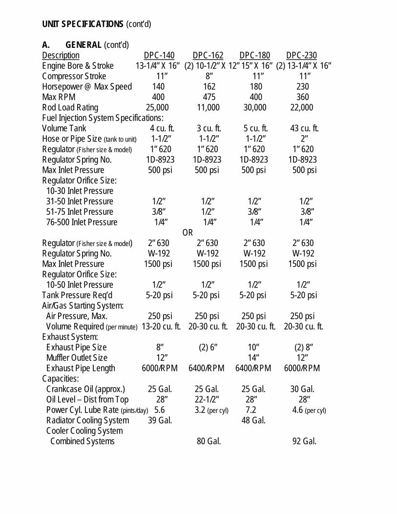
UNIT SPECIFICATIONS (cont’d) A. GENERAL (cont’d) Description DPC-140 DPC-162 DPC-180 DPC-230 Engine Bore & Stroke 13-1/4” X 16” (2) 10-1/2” X 12” 15” X 16” (2) 13-1/4” X 16” Compressor Stroke 11” 8” 11” 11” Horsepower @ Max Speed 140 162 180 230 Max RPM 400 475 400 360 Rod Load Rating 25,000 11,000 30,000 22,000 Fuel Injection System Specifications: Volume Tank 4 cu. ft. 3 cu. ft. 5 cu. ft. 43 cu. ft. Hose or Pipe Size (tank to unit) 1-1/2” 1-1/2” 1-1/2” 2” Regulator (Fisher size & model) 1” 620 1” 620 1” 620 1” 620 Regulator Spring No. 1D-8923 1D-8923 1D-8923 1D-8923 Max Inlet Pressure 500 psi 500 psi 500 psi 500 psi Regulator Orifice Size: 10-30 Inlet Pressure 31-50 Inlet Pressure 1/2” 1/2” 1/2” 1/2” 51-75 Inlet Pressure 3/8” 1/2” 3/8” 3/8” 76-500 Inlet Pressure 1/4” 1/4” 1/4” 1/4” OR Regulator (Fisher size & model) 2” 630 2” 630 2” 630 2” 630 Regulator Spring No. W-192 W-192 W-192 W-192 Max Inlet Pressure 1500 psi 1500 psi 1500 psi 1500 psi Regulator Orifice Size: 10-50 Inlet Pressure 1/2” 1/2” 1/2” 1/2”
Tank Pressure Req’d 5-20 psi 5-20 psi 5-20 psi 5-20 psi Air/Gas Starting System: Air Pressure, Max. 250 psi 250 psi 250 psi 250 psi Volume Required (per minute) 13-20 cu. ft. 20-30 cu. ft. 20-30 cu. ft. 20-30 cu. ft. Exhaust System: Exhaust Pipe Size 8” (2) 6” 10” (2) 8” Muffler Outlet Size 12” 14” 12” Exhaust Pipe Length 6000/RPM 6400/RPM 6400/RPM 6000/RPM Capacities: Crankcase Oil (approx.) 25 Gal. 25 Gal. 25 Gal. 30 Gal. Oil Level – Dist from Top 28” 22-1/2” 28” 28” Power Cyl. Lube Rate (pints/day) 5.6 3.2 (per cyl) 7.2 4.6 (per cyl)
Radiator Cooling System 39 Gal. 48 Gal. Cooler Cooling System Combined Systems 80 Gal. 92 Gal.

UNIT SPECIFICATIONS (cont’d) A. GENERAL (cont’d) Description DPC-280 DPC-300 DPC-360 Engine Bore & Stroke (2)13-1/4”” X 16” (2) 15”” X 16” (2) 15” X 16” Compressor Stroke 11” 11” 11” Horsepower @ Max Speed 280 300 360 Max RPM 400 360 400 Rod Load Rating 25,000 25,000 30,000 Fuel Injection System Specifications: Volume Tank 4 cu. ft. 5 cu. ft. 5 cu. ft. Hose or Pipe Size (tank to unit) 2” 2” 2” Regulator (Fisher size & model) 1” 620 1” 620 1” 620 Regulator Spring No. 1D-8923 1D-8923 1D-8923 Max. Inlet Pressure 500 psi 500 psi 500 psi Regulator Orifice Size: 51-150 Inlet Pressure 1/2” 1/2” 1/2” 150-500 Inlet Pressure 3/8” 3/8” 3/8” OR Regulator (Fisher size & model) 2” 630 2” 630 2” 630 Regulator Spring No. W-192 W-192 W-192 Max Inlet Pressure 1500 psi 1500 psi 1500 psi Regulator Orifice Size: 10-50 Inlet Pressure 1/2” 1/2” 1/2” Tank Pressure Req’d 5-20 psi 5-20 psi 5-20 psi Air/Gas Starting System: Air Pressure, Max. 250 psi 250 psi 250 psi Volume Required (per minute) 20-30 cu. ft. 35-45 cu. ft. 35-45 cu. ft. Exhaust System: Exhaust Pipe Size (2) 8” (2) 10” (2)10” Muffler Outlet Size 12” 14” 14” Exhaust Pipe Length 6000/RPM 6400/RPM 6400/RPM Capacities: Crankcase Oil (approx.) 30 Gal. 30 Gal. 30 Gal. Oil Level – Dist from Top 28” 28” 28” Power Cyl. Lube Rate (pints/day) 5.6 (per cyl) 3.2 (per cyl) 7.2 (per cyl) Cooler Cooling System Combined Systems 95 Gal. 100 Gal. 125 Gal.

UNIT SPECIFICATIONS (cont’d) A. GENERAL (cont’d) Description DPC-600 DPC-800 Engine Bore & Stroke (3)15”” X 16” (4) 15”” X 16” Compressor Stroke 11” 11” Horsepower @ Max Speed 600 800 Max RPM 400 400 Rod Load Rating 40,000 40,000 Fuel Injection System Specifications: Hose or Pipe Size (tank to unit) 2” 2” Volume Tank 10-1/2 cu. ft. 14 cu. ft. Regulator (Fisher size & model) 2” 630 2” 630 Regulator Spring No. W-191 W-191 Max Inlet Pressure 260 psi 260 psi Regulator Orifice Size: 10-50 Inlet Pressure 1/2” 1/2” Tank Pressure Req’d 5-20 psi 5-20 psi Air/Gas Starting System: Air Pressure, Max. 250 psi 250 psi Volume Required (per minute) 50-65 cu. ft. 65-85 cu. ft. Exhaust System: Exhaust Pipe Size (3) 10” (2) 10” Muffler Outlet Size 18” 18” Exhaust Pipe Length 6400/RPM 6400/RPM Capacities: Crankcase Oil (approx.) 58 Gal. 95 Gal. Oil Level – Dist from Top 28” 28” Power Cyl. Lube Rate (pints/day) 8 (per cyl) 8 (per cyl)
Cooler Cooling System Combined Systems 150 Gal. 200 Gal.

UNIT SPECIFICATIONS (cont’d) A. GENERAL (cont’d) Description DPC-2201&LE DPC-2202&LE DPC-2801&LE DPC-2802&LE Engine Bore & Stroke 13-1/4” X 16” (2) 13-1/4” X 16” 15” X 16” (2) 15” X 16” Compressor Stroke 11” 11” 11” 11” Horsepower @ Max Speed 148 296 192 384 Max RPM 440 440 440 440 Rod Load Rating 30,000 30,000 30,000 30,000 Fuel Injection System Specifications: Volume Tank 4 cu. ft. 4 cu. ft. 5 cu. ft. 5 cu. ft. Hose or Pipe Size (tank to unit) 2” 2” 2” 2” Regulator (Fisher size & model) 1” 620 1” 620 1” 620 1” 620 Regulator Spring No. 1D-8923 1D-8923 1D-8923 1D-8923 Max Inlet Pressure 500 psi 500 psi 500 psi 500 psi Regulator Orifice Size: 31-50 Inlet Pressure 1/2” 1/2” 1/2” 51-75 Inlet Pressure 3/8” 3/8” 3/8” 1/2” 76-500 Inlet Pressure 1/4” 1/4” 1/4” 3/8” OR Regulator (Fisher size & model) 2” 630 2” 630 2” 630 2” 630 Regulator Spring No. W-192 W-192 W-192 W-192 Max Inlet Pressure 1500 psi 1500 psi 1500 psi 1500 psi Regulator Orifice Size: 10-50 Inlet Pressure 3/8” 1/2” 1/2” 1/2” Tank Pressure Req’d 5-20 psi 5-20 psi 5-20 psi 5-20 psi Air/Gas Starting System: Air Pressure, Max. 250 psi 250 psi 250 psi 250 psi Volume Required (per minute) 13-20 cu. ft. 20-30 cu. ft. 20-30 cu. ft. 35-45 cu. ft. Exhaust System: Exhaust Pipe Size (1) 8” (2) 8” 10” (2) 10” Muffler Outlet Size 12” 12” 14” 14” Exhaust Pipe Length 6000/RPM 6000/RPM 6400/RPM 6400/RPM Capacities: Crankcase Oil (approx.) 30 Gal. 30 Gal. 25 Gal. 30 Gal. Oil Level – Dist from Top 28” 28” 28” 28” Power Cyl. Lube Rate (pints/day) 4.9 (per cyl) 4.9 (per cyl) 6.4 (per cyl) 6.4 (per cyl) Radiator Cooling System 48 Gal. Cooler Cooling System Engine Jacket Water 26 Gal. Compressor Jacket Water 13 Gal. Combined Systems 92 Gal. 125 Gal.

UNIT SPECIFICATIONS (cont’d) A. GENERAL (cont’d) Description DPC-2803 DPC-2804 DPC-2803LE DPC-2804LE Engine Bore & Stroke (3) 15” X 16” (3) 15” X 16” (4) 15” X 16” (4) 15” X 16” Compressor Stroke 11” 11” 11“ 11” Horsepower @ Max Speed 634 845 600 800 Max RPM 440 440 440 440 Rod Load Rating 40,000 40,000 40,000 40,000 Fuel Injection System Specifications: Volume Tank 10-1/2 cu. ft. 14 cu. ft. 10/1/2 cu. ft. 14 cu. ft. Hose or Pipe Size (tank to unit) 2” 2” 2” 2” Regulator (Fisher size & model) 2” 630 2” 630 2” 630 2” 630 Regulator Spring No. W-191 W-191 W-191 W-191 Max Inlet Pressure 260 psi 260 psi 260 psi 260 psi Regulator Orifice Size: 10-50 Inlet Pressure 1/2” 1/2” 1/2” 1/2” Tank Pressure Req’d 5-20 psi 5-20 psi 5-20 psi 5-20 psi Air/Gas Starting System: Air Pressure, Max. 250 psi 250 psi 250 psi 250 psi Volume Required (per minute) 50-65 cu. ft. 65-85 cu. ft. 50-65 cu. ft. 65-85 cu. ft. Exhaust System: Exhaust Pipe Size (3) 10” (2) 10” (3) 10” (2) 10” Muffler Outlet Size 18” 18” 18” 18” Exhaust Pipe Length 6400/RPM 6400/RPM 6400/RPM 6400/RPM Capacities: Crankcase Oil (approx.) 58 Gal. 95 Gal. 58 Gal. 95 Gal. Oil Level – Dist from Top 28” 28” 28” 28” Power Cyl. Lube Rate (pints/day) 7 (per cyl) 7 (per cyl) 6.7 (per cyl) 6.7 (per cyl) Cooler Cooling System Combined Systems 150 Gal. 200 Gal. 150 Gal. 200 Gal.
UNIT SPERCIFICATIONS (cont’d)
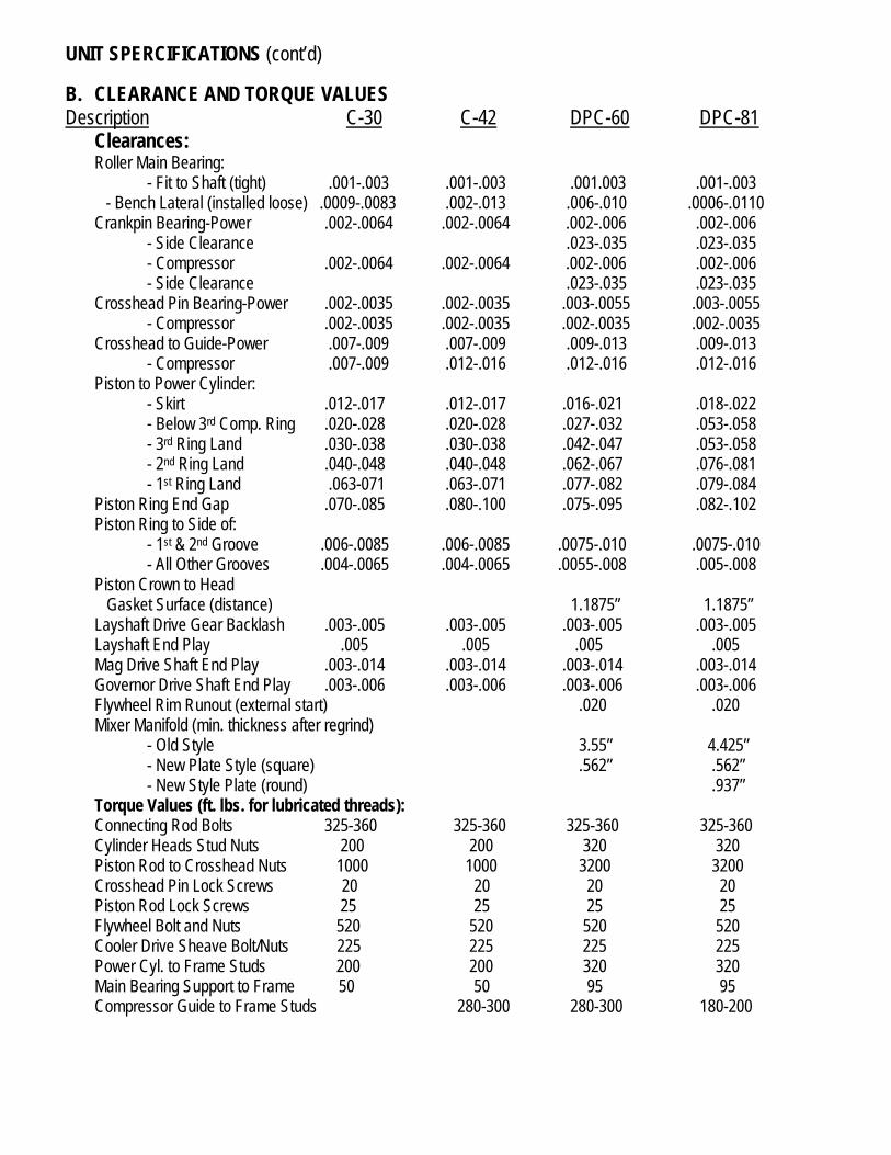
B. CLEARANCE AND TORQUE VALUES Description C-30 C-42 DPC-60 DPC-81 Clearances: Roller Main Bearing: - Fit to Shaft (tight) .001-.003 .001-.003 .001.003 .001-.003 - Bench Lateral (installed loose) .0009-.0083 .002-.013 .006-.010 .0006-.0110 Crankpin Bearing-Power .002-.0064 .002-.0064 .002-.006 .002-.006 - Side Clearance .023-.035 .023-.035 - Compressor .002-.0064 .002-.0064 .002-.006 .002-.006 - Side Clearance .023-.035 .023-.035 Crosshead Pin Bearing-Power .002-.0035 .002-.0035 .003-.0055 .003-.0055 - Compressor .002-.0035 .002-.0035 .002-.0035 .002-.0035 Crosshead to Guide-Power .007-.009 .007-.009 .009-.013 .009-.013 - Compressor .007-.009 .012-.016 .012-.016 .012-.016 Piston to Power Cylinder: - Skirt .012-.017 .012-.017 .016-.021 .018-.022 - Below 3rd Comp. Ring .020-.028 .020-.028 .027-.032 .053-.058 - 3rd Ring Land .030-.038 .030-.038 .042-.047 .053-.058 - 2nd Ring Land .040-.048 .040-.048 .062-.067 .076-.081 - 1st Ring Land .063-071 .063-.071 .077-.082 .079-.084 Piston Ring End Gap .070-.085 .080-.100 .075-.095 .082-.102 Piston Ring to Side of: - 1st & 2nd Groove .006-.0085 .006-.0085 .0075-.010 .0075-.010 - All Other Grooves .004-.0065 .004-.0065 .0055-.008 .005-.008 Piston Crown to Head Gasket Surface (distance) 1.1875” 1.1875” Layshaft Drive Gear Backlash .003-.005 .003-.005 .003-.005 .003-.005 Layshaft End Play .005 .005 .005 .005 Mag Drive Shaft End Play .003-.014 .003-.014 .003-.014 .003-.014 Governor Drive Shaft End Play .003-.006 .003-.006 .003-.006 .003-.006 Flywheel Rim Runout (external start) .020 .020 Mixer Manifold (min. thickness after regrind) - Old Style 3.55” 4.425” - New Plate Style (square) .562” .562” - New Style Plate (round) .937” Torque Values (ft. lbs. for lubricated threads): Connecting Rod Bolts 325-360 325-360 325-360 325-360 Cylinder Heads Stud Nuts 200 200 320 320 Piston Rod to Crosshead Nuts 1000 1000 3200 3200 Crosshead Pin Lock Screws 20 20 20 20 Piston Rod Lock Screws 25 25 25 25 Flywheel Bolt and Nuts 520 520 520 520 Cooler Drive Sheave Bolt/Nuts 225 225 225 225 Power Cyl. to Frame Studs 200 200 320 320 Main Bearing Support to Frame 50 50 95 95 Compressor Guide to Frame Studs 280-300 280-300 180-200

UNIT SPERCIFICATIONS (cont’d)
B. CLEARANCE AND TORQUE VALUES (cont’d) Description DPC-80-A DPC-105 DPC-115 DPC-140&2201 Clearances: Roller Main Bearing: - Fit to Shaft (tight) .0015-.003 .0015-.003 .002.004 .002-.004 - Bench Lateral (installed loose) .015-.006 .015-.006 .0003-.0074 .0003-.0074 Crankpin Bearing-Power .003-.007 .003-.007 .003-.006 .003-.006 - Side Clearance .010-.026 .010-.026 - Compressor .002-.006 .002-.006 .003-.006 .003-.006 - Side Clearance .010-.026 .010-.026 Crosshead Pin Bearing-Power .002-.0035 .002-.0035 .0044-.0074 .0044-.0074 - Compressor .003-.0055 .002-.0055 .003-.0055 .003-.0055 Crosshead to Guide-Power .009-.012 .009-.012 .009-.013 .009-.013 - Compressor .012-.015 .012-.015 .012-.015 .012-.015 Piston to Power Cylinder: - Skirt .017-.023 .022-.028 .025-.031 .025-.031 - Below 3rd Comp. Ring .037-.043 .042-.048 .070-.079 .070-.079 - 3rd Ring Land .057-.063 .062-.068 .127-.136 .127-.136 - 2nd Ring Land .077-.083 .082-.088 .127-.136 .127-.136 - 1st Ring Land .092-.098 .097-.103 .137-.146 .137-.146 Piston Ring End Gap .085-.105 .095-.115 .100-.120 .100-.120 Piston Ring to Side of: - 1st & 2nd Groove .0075-.010 .0075-.010 .010-.0125 .010-.0125 - All Other Grooves .0055-.008 .0055-.008 .008-.0105 .008-.0105 Piston Crown to Head Gasket Surface (distance) 1.250” 1.250” 2.250” 2.250” Layshaft Drive Gear Backlash .003-.005 .003-.005 .003-.005 .003-.005 Layshaft End Play .005 .005 .005 .005 Mag Drive Shaft End Play .003-.014 .003-.014 .003-.014 .003-.014 Governor Drive Shaft End Play .003-.006 .003-.006 .003-.006 .003-.006 Flywheel Rim Runout (external start) .020 .020 Mixer Manifold (min. thickness after regrind) - Old Style 4.425” 4.425” 4.425” 4.425” - New Plate Style (square) .562” .562” .562” .562” Torque Values (ft. lbs. for lubricated threads): Connecting Rod Bolts - Power-End 650-700 650-700 650-700 650-700 - Compressor-End 325-360 325-360 650-700 650-700 Cylinder Heads Stud Nuts 320 550 490 490 Piston Rod to Crosshead Nuts 2000 3200 3200 3200 Crosshead Pin Lock Screws 50 50 50 50 Piston Rod Lock Screws 50 50 50 50 Flywheel Bolt and Nuts 520 520 520 520 Cooler Drive Sheave Bolt/Nuts 225 225 225 225 Power Cyl. to Frame Studs 320 320 490 490 Main Bearing Support to Frame 95 95 150 150 Compressor Guide to Frame Studs 180-200 180-200 180-200 180-200

UNIT SPERCIFICATIONS (cont’d) B. CLEARANCE AND TORQUE VALUES (cont’d) Description DPC-162 DPC-180&2801 DPC-230 DPC-280&2202 Clearances Roller Main Bearing: - Fit to Shaft (tight) .001-.003 .002-.004 .002.004 .002-.004 - Bench Lateral (installed loose) .006-.011 .0003-.0074 .0003-.0074 .0003-.0074 Center Main Bearing: .004-.007 .004-.007 .004-.007 Crankpin Bearing-Power .002-.006 .003-.007 .003-.006 .003-.006 - Side Clearance .023-.035 .010-.026 .010-.026 - Compressor .002-.006 .002-.006 .003-.006 .003-.006 - Side Clearance .023-.035 .010-.026 .010-.026 Crosshead Pin Bearing-Power .003-.0055 .002-.0035 .0044-.0074 .0044-.0074 - Compressor .002-.0035 .002-.0055 .003-.0055 .003-.0055 Crosshead to Guide-Power .009-.013 .009-.012 .009-.013 .009-.013 - Compressor .012-.016 .012-.015 .012-.015 .012-.015 Piston to Power Cylinder: - Skirt .018-.022 .022-.028 .025-.031 .025-.031 - Below 3rd Comp. Ring .053-.058 .042-.048 .070-.079 .070-.079 - 3rd Ring Land .053-.058 .062-.068 .127-.136 .127-.136 - 2nd Ring Land .076-.081 .082-.088 .127-.136 .127-.136 - 1st Ring Land .079-.084 .097-.103 .137-.146 .137-.146 Piston Ring End Gap .082-.102 .095-.115 .100-.120 .100-.120 Piston Ring to Side of: - 1st & 2nd Groove .0075-.010 .0075-.010 .010-.0125 .010-.0125 - All Other Grooves .0055-.008 .0055-.008 .008-.0105 .008-.0105 Piston Crown to Head Gasket Surface (distance) 1.1875” 1.250” 2.250” 2.250” Layshaft Drive Gear Backlash .003-.005 .003-.005 .003-.005 .003-.005 Layshaft End Play .005 .005 .005 .005 Mag Drive Shaft End Play .003-.014 .003-.014 .003-.014 .003-.014 Governor Drive Shaft End Play .003-.006 .003-.006 .003-.006 .003-.006 Flywheel Rim Runout (external start) .020 .020 Mixer Manifold (min. thickness after regrind) - Old Style 4.425” 4.425” 4.425” - New Plate Style (square) .562” .562” .562” - New Style Plate (round) .937 Torque Values (ft. lbs. for lubricated threads): Connecting Rod Bolts - Power-End 325-360 650-700 650-700 650-700 - Compressor-End 325-360 325-360 650-700 650-700 Cylinder Heads Stud Nuts 320 600 490 490 Piston Rod to Crosshead Nuts 3200 3200 3200 3200 Crosshead Pin Lock Screws 20 50 50 50 Piston Rod Lock Screws 20 50 50 50 Flywheel Bolt and Nuts 520 520 520 520 Cooler Drive Sheave Bolt/Nuts 225 225 225 225 Power Cyl. to Frame Studs 320 490 490 490 Main Bearing Support to Frame 150 150 150 150 Center Main Cap Bolts 250-265 250-265 250-265 Center Main Carrier to Frame Bolts 95 95 95 Compressor Guide to Frame Studs 180-200 180-200 280-300 280-300

UNIT SPERCIFICATIONS (cont’d) B. CLEARANCE AND TORQUE VALUES (cont’d) Description DPC-300 DPC-360&2802 Clearances: Roller Main Bearing: - Fit to Shaft (tight) .002-.004 .002-.004 - Bench Lateral (installed loose) .0003-.0074 .0021-.0085 Center Main Bearing: .004-.007 .004-.007 Crankpin Bearing-Power .003-.006 .003-.006 - Side Clearance .010-.026 .010-.026 - Compressor .003-.006 .003-.006 - Side Clearance .010-.026 .010-.026 Crosshead Pin Bearing-Power .0044-.0074 .0044-.0074 - Compressor .003-.006 .0035-.0055 Crosshead to Guide-Power .008-.012 .009-.015 - Compressor .012-.015 .012-.015 Piston to Power Cylinder: - Skirt .027-.033 .027-.033 - Below 3rd Comp. Ring .067-.076 .067-.076 - 3rd Ring Land .142-.151 .142-.151 - 2nd Ring Land .142-.151 .142-.151 - 1st Ring Land .152-.161 .152-.161 Piston Ring End Gap .115-.135 .115-.135 Piston Ring to Side of: - 1st & 2nd Groove .010-.0125 .010-.0125 - All Other Grooves .008-.0105 .008-.0105 Piston Crown to Head Gasket Surface (distance) 2.250” 2.250” Layshaft Drive Gear Backlash .003-.005 .003-.005 Layshaft End Play .005 .005 Mag Drive Shaft End Play .003-.014 .003-.014 Governor Drive Shaft End Play .003-.006 .003-.006 Flywheel Rim Runout (external start) .020 .020 Mixer Manifold (min. thickness after regrind) - Old Style 4.425” 4.425” - New Plate Style (square) .562” .562” Torque Values (ft. lbs. for lubricated threads): Connecting Rod Bolts - Power-End 650-700 650-700 - Compressor-End 650-700 650-700 Cylinder Heads Stud Nuts 600 600 Piston Rod to Crosshead Nuts 3200 3200 Crosshead Pin Lock Screws 50 50 Piston Rod Lock Screws 50 50 Flywheel Bolt and Nuts 520 520 Cooler Drive Sheave Bolt/Nuts 225 225 Power Cyl. to Frame Studs 490 490 Main Bearing Support to Frame 150 150 Center Main Cap Bolts 250-265 250-265 Center Main Carrier to Frame Bolts 95 95 Compressor Guide to Frame Studs 280-300 280-300

UNIT SPERCIFICATIONS (cont’d)
B. CLEARANCE AND TORQUE VALUES (cont’d) Description DPC-600&2803 DPC-800&2804 Clearances: Main Bearing: .0046-.0076 .0046-.0076 Thrust Bearing Side Clearance .008-.018 .008-.018 Crankpin Bearing-Power .003-.006 .003-.006 - Side Clearance .010-.026 .010-.026 - Compressor .003-.006 .003-.006 - Side Clearance .022-.036 .022-.036 Crosshead Pin Bearing-Power .0044-.0074 .0044-.0074 - Compressor .0035-.0055 .0035-.0055 Crosshead to Guide-Power .009-.013 .009-.015 - Compressor .012-.015 .012-.015 Piston to Power Cylinder: - Skirt .027-.033 .027-.033 - Below 3rd Comp. Ring .077-.086 .077-.086 - 3rd Ring Land .142-.151 .142-.151 - 2nd Ring Land .142-.151 .142-.151 - 1st Ring Land .152-.161 .152-.161 Piston Ring End Gap .115-.135 .115-.135 Piston Ring to Side of: - 1st & 2nd Groove .010-.0125 .010-.0125 - All Other Grooves .008-.0105 .008-.0105 Piston Crown to Head Gasket Surface (distance) 2.250” 2.250” Layshaft Drive Gear Backlash .003-.005 .003-.005 Layshaft End Play .005 .005 Mag Drive Shaft End Play .003-.014 .003-.014 Governor Drive Shaft End Play .003-.006 .003-.006 Flywheel Rim Runout (external start) .020 .020 Mixer Manifold (min. thickness after regrind: - New Plate Style (square) .562” .562” Torque Values (ft. lbs. for lubricated threads): Connecting Rod Bolts - Power-End 650-700 650-700 - Compressor-End 650-700 650-700 Frame Tie-Bar Bolts 260 260 Main Cap Studs (in frame) 250 250 Main Cap Nuts 360 360 Cylinder Heads Stud Nuts 600 600 Piston Rod to Crosshead Nuts 3200 3200 Crosshead Pin Lock Screws 50 50 Piston Rod Lock Screws 50 50 Flywheel Bolt and Nuts (split style) 520 Flywheel Bolts (Ringfeder) 185 Cooler Drive Sheave Bolt/Nuts 225 Cooler Drive Sheave (Ringfeder) 185 Vibration Damper Bolts 225 Power Cyl. to Frame Studs 490 490 Compressor Guide to Frame Studs 280-300 280-300

UNIT SPERCIFICATIONS (cont’d)
C. Wear Limits 13-1/4” and 15” Bore Units ONLY Description As New Limits Max. Acceptable Power-End 13-1/4” Cylinder Bore 13.247-13.251 13.263, Max of .002 TIR 13-1/4” Piston Skirt Diameter 13.220-13.222 13.213 13-1/4” Piston-to-Cylinder Clearance .025-.031 .045 13-1/4” Piston Ring 1 & 2 Side Clearance .010-.0125 .015 13-1/4” Piston Ring 3 & 4 Side Clearance .008-.0105 .013 13-1/4” Piston Ring End Gap .100-.126 .145 15” Cylinder Bore 14.997-15.001 15.013, Max of .002 TIR 15” Piston Skirt Diameter 14.968-14.970 14.961 15” Piston-to-Cylinder Clearance .027-.033 .045 15” Piston Ring 1 & 2 Side Clearance .010-.0125 .015 15” Piston Ring 3 & 4 Side Clearance .008-.0105 .013 15” Piston Ring End Gap .115-.135 .145 Piston Rod O.D. 2.497-2.500 2.495 Crosshead Guide 12.000-12.002 12.004 Crosshead O.D. 11.987-11.989 11.985 Crosshead-to-Guide Clearance .009-.013 .016 Connecting Rod Pin Bushing I.D. 5.5044-5.5069 5.509 Connecting Rod Side Clearance .010-.026 .029 Crosshead Pin O.D. 5.4995-5.500 5.4985, Max .001 TIR Crosshead-to-Pin Clearance .0044-.0074 .0085 Connecting Rod Bearing Bore 7.503-7.505 7.507, Max .001 TIR Crank Pin O.D. 7.499-7.500 7.4975, Max .0015 TIR Crank Pin-to-Bearing I.D. Clearance .0044-.006 .0075 Main Bearing Journal O.D. 8.374-8.375 8.3725 Main Bearing I.D. 8.3796-8.3816 8.3831, Max .002 TIR Main Journal-to-Bearing I.D. Clearance .0046-.0076 .0091 Main Bearing Thrust (600, 800, 2803 & 2804 only) .010-.020 .022 Layshaft Bearing Bore 1.502-1.503 1.504 Layshaft O.D. 1.498-1.500 1.497 Layshaft O.D.-to-Bearing Clearance .002-.005 .007 Center Main Bearing I.D. (2 cyl units only) 7.754-7.756 7.757 Crankshaft Journal O.D. (2 cyl units only) 7.749-7.750 7.748 Center Main-to-Journal Clearance (2 cyl only) .004-.007 .0084
Note: Specific Unit Performance and Maintenance Requirements May Vary Based on Application Conditions and Maintenance Practices. These Component Dimensional Specifications and Wear Limits Should Be Used as a Guide for Maintenance Programs for Ajax Equipment.

UNIT SPERCIFICATIONS (cont’d)
C. Wear Limits 13-1/4” and 15” Bore Units ONLY Description As New Limits Max. Acceptable Compressor-End Piston Rod, 2-1/2” 2.497-2.500 2.495 Piston Rod, 2-1/4” 2.249-2.250 2.2455 Crosshead Guide 11.999-12.001 12.008 Crosshead O.D. 11.984-11.986 11.982 Crosshead-to-Guide Clearance .011-.015 .018 Connecting Rod Pin Bushing I.D. 4.5035-4.5062 4.507 Crosshead Pin O.D. 4.4995-4.500 4.4985 Crosshead-to-Pin Clearance .0044-.006 .0066 Connecting Rod Bearing I.D. 7.503-7.505 7.506 Crank Pin O.D. 7.499-7.500 7.498 Crank Pin-to-Bearing Clearance .0042-.0066 .008
Note: Specific Unit Performance and Maintenance Requirements May Vary Based on Application Conditions and Maintenance Practices. These Component Dimensional Specifications and Wear Limits Should Be Used as a Guide for Maintenance Programs for Ajax Equipment.