
DATA-MANFULL PMP1000 565 567 ENG Rev Aimages.miretail.com/...DE83-49B4-981B-FDAE5B7920A3.pdf · a p...
17
Version 1.0 November 2006 User Manual !"#$%$&!# %(%)***+%(%,***+%(%-***
Transcript of DATA-MANFULL PMP1000 565 567 ENG Rev Aimages.miretail.com/...DE83-49B4-981B-FDAE5B7920A3.pdf · a p...

Version 1.0 November 2006
User Manual
!"
#$
%$
&!
#''''%
(%
)*
**
+%
(%
,*
**
+%
(%
-*
**

2
!"#$%$&!#'%(%)***+%(%,***+%(%-***
This symbol, wherever it appears, alerts you to the
presence of uninsulated dangerous voltage inside
the enclosure—voltage that may be sufficient to
constitute a risk of shock.
This symbol, wherever it appears, alerts you to
important operating and maintenance instructions
in the accompanying literature. Please read themanual.
IMPORTANT SAFETY INSTRUCTIONS
CAUTION: To reduce the risk of electric shock, do not remove
the top cover (or the rear section). No user
serviceable parts inside; refer servicing to qualified
personnel.
WARNING: To reduce the risk of fire or electric shock, do not
expose this appliance to rain and moisture. The
apparatus shall not be exposed to dripping or
splashing and no objects filled with liquids, such
as vases, shall be placed on the apparatus.
1) Read these instructions.
2) Keep these instructions.
3) Heed all warnings.
4) Follow all instructions.
5) Do not use this apparatus near water.
6) Clean only with dry cloth.
7) Do not block any ventilation openings. Install in
accordance with the manufacturer’s instructions.
8) Do not install near any heat sources such as radiators,
heat registers, stoves, or other apparatus (including
amplifiers) that produce heat.
9) Do not defeat the safety purpose of the polarized or
grounding-type plug. A polarized plug has two blades
with one wider than the other. A grounding type plug
has two blades and a third grounding prong. The wideblade or the third prong are provided for your safety. If
the provided plug does not fit into your outlet, consult
an electrician for replacement of the obsolete outlet.
10) Protect the power cord from being walked on or
pinched particularly at plugs, convenience receptacles,
and the point where they exit from the apparatus.
11) The apparatus shall be connected to a MAINS socket
outlet with a protective earthing connection.
12) Where the MAINS plug or an appliance coupler is
used as the disconnect device, the disconnect device
shall remain readily operable.
13) Only use attachments/accessories specified by the
manufacturer.
14) Use only with the cart, stand, tripod, bracket, or table
specified by the manufacturer, or sold with the
apparatus. When a cart is used, use caution when moving
the cart/apparatus combination to avoid injury from
tip-over.
15) Unplug this apparatus during lightning storms or
when unused for long periods of time.
16) Refer all servicing to qualified service personnel.
Servicing is required when the apparatus has been
damaged in any way, such as power supply cord or plug
is damaged, liquid has been spilled or objects have fallen
into the apparatus, the apparatus has been exposed to
rain or moisture, does not operate normally, or has been
dropped.
17) CAUTION - These service instructions are for use by
qualified service personnel only. To reduce the risk of
electric shock do not perform any servicing other than
that contained in the operation instructions unless youare qualified to do so.

3
!"#$%$&!#'%(%)***+%(%,***+%(%-***
FOREWORD
Dear Customer,
Welcome to the team of
EUROPOWER users
and thank you very much
for expressing your confi-dence in BEHRINGER
products by purchasing
this power mixer.
It is one of my most
pleasant tasks to write
this letter to you, because
it is the culmination of
many months of hard
work delivered by our
engineering team to reach
a very ambitious goal:
to present you three
outstanding powermixers that give you
maximum flexibility and
performance with a unique sound character and broad range of
striking functions. The task to design the new PMP series certainly
meant a great deal of responsibility, which we assumed by
focusing on you, the discerning user and musician. It also meant
a lot of work and night shifts to accomplish this goal. But it was
fun, too. Developing a product usually brings a lot of people
together, and what a great feeling it is when everybody who
participated in such a project can be proud of what we’ve
achieved.
It is our philosophy to share our joy with you, because you
are the most important member of the BEHRINGER team. Withyour highly competent suggestions for new products you’ve
greatly contributed to shaping our company and making it
successful. In return, we guarantee you uncompromising quality
as well as excellent technical and audio properties at an extremely
favorable price. All of this will enable you to fully unfold your
creativity without being hampered by budget constraints.
We are often asked how we can make it to produce such high-
grade devices at such unbelievably low prices. The answer is
quite simple: it’s you, our customers! Many satisfied customers
means large sales volumes enabling us to get better conditions
of purchase for components, etc. Isn’t it only fair to pass this
benefit back to you? Because we know that your success is our
success, too!
I would like to thank all people whose help on “Project PMP”
has made it all possible. Everybody has made very personal
contributions, starting from the designers of the unit to the many
staff members in our company and finally to you, the user of
BEHRINGER products.
My friends, it’s been worth the trouble!
Thank you very much,
Uli Behringer CAUTION!
! We would like to point out that high volume levels may
damage your hearing and/or your headphones. Please
move down all faders in the MAIN section before turning
on the device. Always make sure that the appropriate
volume is set.
TABLE OF CONTENTS
1 INTRODUCTION ......................................................... 4
1.1 Before you get started ................................................... 4
1.1.1 Shipment ............................................................... 4
1.1.2 Initial operation ...................................................... 4
1.1.3 Online registration ................................................ 4
1.2 The manual ..................................................................... 4
2 CONTROL ELEMENTS ............................................... 5
2.1 Mono and stereo channels ............................................ 5
2.1.1 Input section ......................................................... 5
2.2 Equalizer and FBQ .......................................................... 6
2.3 Effects section ............................................................... 7
2.4 Main and monitor section ................................................ 7
2.4.1 Connectors ........................................................... 8
2.5 Rear panel ...................................................................... 8
3 DIGITAL EFFECTS PROCESSOR ................................ 8
4 INSTALLATION ........................................................... 9
4.1 Mains connection ........................................................... 9
4.2 Audio connections ......................................................... 9
4.3 Loudspeaker connections ........................................... 10
5 WIRING EXAMPLES ................................................. 11
6 SPECIFICATIONS .....................................................14
7 WARRANTY .............................................................. 16
FCC— FEDERAL COMMUNICATIONS COMMISSIONCOMPLIANCE INFORMATION .................................. 17

4
!"#$%$&!#'%(%)***+%(%,***+%(%-***
1 INTRODUCTION
Congratulations! With the PMP1000/PMP3000/PMP5000 you
have acquired a state-of-the-art power mixer that sets new
standards. Right from the very start it has been our goal to
design a revolutionary unit that can be used for a wide variety of
applications. Indeed, this overwhelming power mixer gives you
plenty of functionality and a broad range of connection and
expansion options.
Your PMP features our revolutionary COOLAUDIO amplifier
technology, which reduces the weight and size of the unit
considerably and ensures extremely high output power.
Further advantages are the integrated Voice Canceller that
removes vocal passages from playbacks, the FBQ function,
which detects feedback frequencies, and the Speaker
Processing function for loudspeaker alignment—all with a
resolution of 24 bits and 40 kHz. Plus, our tried and tested
XENYX Mic Preamps give you crystal-clear audio free of noise
and distortion when using microphones.
BEHRINGER is a company with its roots in professional
recording studio technology. For many years we have been
successful in developing products for studio and live use. These
include microphones and 19" units of all types (compressors,
enhancers, noise gates, tube processors, headphone amplifiers,
digital effects, DI boxes, etc.), monitor and P.A. speakers andprofessional live and recording mixers. Our entire technical know-
how has gone into your PMP power mixer.
1.1 Before you get started
1.1.1 Shipment
Your PMP was carefully packed at the factory and the
packaging is designed to protect the unit from rough handling.
Nevertheless, we recommend that you carefully examine thepackaging and its contents for any signs of physical damage
which may have occurred during transit.
! If the unit is damaged, please do NOT return it to
BEHRINGER, but notify your dealer and the shipping
company immediately. Otherwise, claims fordamage or replacement may not be granted.
! We recommend that you use a flight case, so as to
give your power mixer optimum protection during
use or transport.
! Always use the original packing carton to prevent
damage during storage or transport.
! Make sure that children cannot play unsupervised
with the device or its packaging.
! Please ensure proper disposal of all packing
materials.
1 INTRODUCTION
1.1.2 Initial operation
Be sure that there is enough air space around the unit for
cooling and, to avoid overheating, please do not place the
EUROPOWER near radiators, etc.
! Blown fuses must be replaced by fuses of the same
type and rating! Please refer to the
“SPECIFICATIONS” for details.
The mains connection is made using the enclosed power cord
and a standard IEC receptacle. It meets all of the international
safety certification requirements.
! Please make sure that all units have a proper
ground connection. For your own safety, never
remove or disable the ground conductor from the
unit or on the AC power cord.
To avoid damage on the device, do not
- earth the loudspeaker outputs
- connect the loudspeaker outputs to each other
- connect the loudspeaker outputs to those of otheramplifiers
IMPORTANT NOTES CONCERNING INSTALLATION
The sound quality may diminish within the range of powerful
broadcasting stations and high-frequency sources. Increasethe distance between the transmitter and the device and use
shielded cables for all connections.
1.1.3 Online registration
Please do remember to register your new BEHRINGER
equipment right after your purchase by visiting
www.behringer.com (alternatively www.behringer.de) and
kindly read the terms and conditions of our warranty carefully.
Should your BEHRINGER product malfunction, our goal is to
have it repaired as quickly as possible. To arrange for warranty
service, please contact the retailer from whom the equipmentwas purchased. Should your BEHRINGER dealer not be located
in your vicinity, you may directly contact one of our subsidiaries.
Corresponding contact information is included in the original
equipment packaging (Global Contact Information/European
Contact Information). Should your country not be listed, please
contact the distributor nearest you. A list of distributors can be
found in the support area of our website (www.behringer.com).
Registering your purchase and equipment with us helps us
process your repair claims quicker and more efficiently.
Thank you for your cooperation!
1.2 The manual
This manual is designed to give you both an overview of all
control elements and to provide details about how to use them.
To provide you with a clear structure, we have grouped the
control elements according to their function. They can easily be
found on the enclosed numbered illustrations. If you need more
detailed information on specific topics, please visit our web site
at www.behringer.com.

5
!"#$%$&!#'%(%)***+%(%,***+%(%-***
2 CONTROL ELEMENTS
2 CONTROL ELEMENTS
A detailed description of all functions of your power mixer can
be found in the following chapters. Please also refer to the
enclosed sheet with the numbered illustrations to get a good
overview of the control layout.
2.1 Mono and stereo channels
Use the TRIM control to adjust the input gain. Be sure to
set this control fully counter-clockwise before you connect
or disconnect a signal source to an input. TRIM controlsboth the microphone and the LINE input. The black scale
shows the microphone gain (+10 to +60 dB on channels
with XENYX MIC PREAMPS and 0 to +40 dB on conventional
microphone inputs; PMP1000 only, channels 5/6 and 7/8).
The “LINE” scale indicates the sensitivity of the LINE input,
ranging from +10 to -40 dBu.
PMP1000: The mono/stereo combination channels 5/6 and
7/8 have a sensitivity of +20 to -20 dBu.
The LEVEL SET LED illuminates when an optimum operating
level has been adjusted.
The mono channels are equipped with a high-slope LOWCUT filter eliminating unwanted low-frequency signals like
rumble noise.
PMP3000/PMP5000 (stereo channels): Press the A/B button
to switch from 1/4" jacks to RCA connectors, and vice
versa. Position “A” = 1/4" jacks; position “B” = RCAconnectors.
The HIGH control in the EQ section governs the high
frequency range of the respective channel.
Use the MID control to boost or cut the midrange
frequencies.
PMP5000: The PMP5000 has an additional semi-parametric
filter for the midrange frequencies in the mono channels
(tunable from 100 Hz to 8 kHz). Adjust the boost/cut with
the MID control, and the frequency with the FREQ control.
The stereo channels contain a stereo EQ section. The cut-off frequencies of the high and low bands are 12 kHz and
80 Hz respectively, while the center frequencies of the
high-mid and low-mid bands are 3 kHz and 400 Hz
respectively.
The LOW control allows you to boost/cut the low frequencyrange.
With the MON(ITOR) control you can adjust the volume of
each channel in the monitor mix.
The PMP3000 and PMP5000 feature a second MON control
(MON 2) for the volume of the second monitor bus.
The FX control determines the signal level sent from each
channel to the built-in effects processor; this signal is also
present at the FX SEND jack (see ).
The PMP5000 has two FX controls (FX 1 and FX 2), so that
you can use two effects simultaneously. Accordingly, thePMP5000 also has two effect aux buses, which have one
output jack in common (see and ).
! Please note that the effects processor signal will
be inaudible, as long as the FX TO MON/MAIN
controls , , are set fully counter-
clockwise.
The PAN(ORAMA) control determines the position of the
channel signal in the stereo main mix.
The BAL(ANCE) control for the stereo channels
corresponds to the PAN control for the mono channels. It
determines the relative volume of the left and right input
signals before they are routed to the stereo main output.
PMP3000/PMP5000: When you press the PFL button (Pre
Fader Listening) the left LED shows the pre-fader
input gain of the channel. Adjust the optimum input gain (0
dB) with the TRIM control . When PFL is on, the corres-
ponding LED illuminates.
If the LEVEL SET LED is illuminated constantly, the
signal is within the optimum operating level range. However,
if the CLIP LED indicates that the input gain is too high, you
should reduce the level slightly with the TRIM control. The
CLIP LED should never be illuminated all the time, only with
signal peaks.
The MUTE switch mutes the channel in the main mix. The
pre-fader signals (monitor buses) remain operative. When
MUTE is pressed, the corresponding control LED illuminates.
The channel fader controls the channel signal level in the
main mix.
2.1.1 Input section
Each mono input channel is equipped with a balanced
microphone input (XLR connector) which provides
+48 V phantom power for condenser microphones at the
touch of a button (see rear panel).
PMP1000: The two stereo channels 5/6 and 7/8 have an
additional balanced XLR microphone input with +48 V
phantom power.
! Be sure to switch off your audio system before you
activate the phantom power supply to protect your
monitor speakers from switch-on thumps.
Each mono input features one LINE IN connector
(1/4" jack), which can be used with either balanced or
unbalanced signals.
! Please remember to use either the microphone or
the line input on a specific channel. Never use both
at the same time!
! When you connect a mono line signal to a stereo
channel, always use the left input. The mono signal
will then be reproduced by both sides equally.
! PMP1000: This does not apply to the mono/stereo
combination channels 5/6 and 7/8.
INSERT I/O. Insert points or simply inserts are used to
process a signal with dynamic processors or equalizers.
They are pre-fader, pre-EQ and pre-MON/FX SEND. Unlike
reverb and other effects, which are usually added to the
dry signal, dynamic processors usually process the entire
signal. So, aux send buses are not the best solution.
Dynamic processors need to be inserted directly into the
signal path. Once processed, the signal then returns to the
mixing console at the same point where it left. Signalinterruption takes place only if a plug is inserted into the
corresponding jack (1/4" stereo plug: tip = signal output,
ring = input). All mono input channels are equipped with
inserts.
The stereo channels have a TRIM control for gain
adjustment, with the input sensitivity ranging from +20 to-20 dB.
PMP1000: The stereo channels 5/6 and 7/8 feature an
additional XLR connector for microphones whose gain
can be set from 0 to +40 dB.
Each stereo channel has two line-level inputs (1/4" jacks)
for the left and right channels. If only the jack marked “L” is
used, the channel is mono. The signal will then be
reproduced on both sides.
! PMP1000: This does not apply to the mono/stereo
combination channels 5/6 and 7/8.

6
!"#$%$&!#'%(%)***+%(%,***+%(%-***
2 CONTROL ELEMENTS
! PMP1000: Channels 13/14 and 15/16 are routed to
the main mix without additional tone or volume
adjustment. For example, using the channels 13/14
and 15/16 you can connect a submixer and utilize
the PMP1000’s power amplifier.
PMP3000: The stereo channels 9/10 and 11/12 are equipped
with additional RCA connectors.
PMP5000: The stereo channels 13/14 and 15/16 are
equipped with additional RCA connectors.
! PMP3000/PMP5000: Please note that you need to set
the A/B selector to A (1/4") or B (RCA) when you
connect a signal to the input.
PMP3000/PMP5000: Each of the two stereo channels has
two monitor controls (MON 1/2) and a LEVEL control .
Like the other channels, they also feature a PFL switch.
Instead of a fader this channel has a rotary LEVEL control.
The phantom power supply provides the voltage necessary
for the operation of condenser microphones. Use the
PHANTOM switch to activate the supply for the XLR
connectors of the input channels. The +48 V LED will
illuminate when phantom power is on. In most cases,dynamic microphones can still be used, as long as they are
connected in a balanced configuration. If in doubt, please
contact the manufacturer of your microphone!
! With phantom power switched on, you must never
connect microphones to the console (or to a stage/
wall box). Also, be sure to mute the monitor/P.A.
speakers, before you turn on the phantom power
supply. After switching on, please allow the system
to stabilize for about one minute, before you adjustthe input gain.
! Caution! Never use unbalanced XLR connectors
(pins 1 and 3 interconnected) on the MIC input jacks,
if you are going to use the phantom power supply.
The AMP MODE switch determines the mode of operation
of the PMP amplifier stage:
PMP1000:
MAIN: In the “MAIN” position the mixer works as a stereo
amplifier.
MON: In this mode the monitor signal is present at OUTPUT
A and the main signal at OUTPUT B (both are
mono).
BRIDGE (bridged mono mode): In BRIDGE AMP MODEthe output power of OUTPUT A is added to that of OUTPUT
B, i.e. OUTPUT B delivers twice its normal output power.
PMP3000/PMP5000:
MAIN L/MAIN R. In position MAIN MIX, the mixer works as
a stereo amplifier.
MON 1/MONO. In this mode the monitor 1 signal is present
at OUTPUT A and the main signal at OUTPUT B
(both are mono).
BRIDGE (bridged mono mode): In BRIDGE AMP MODEthe output power of OUTPUT A is added to that of OUTPUT
B, i.e. OUTPUT B delivers twice its normal output power.
! In BRIDGE mode, always connect only one
loudspeaker with an impedance of at least 8 ΩΩΩΩΩ to
the OUTPUT B jack! Please note that OUTPUT A must
NEVER be used in BRIDGE mode!
! In all other operating modes, the minimumimpedance of the speaker must not fall below 4 ΩΩΩΩΩ.
! Please note that the power delivered to the speaker
connected to OUTPUT B in BRIDGE AMP MODE is
considerably higher than the power provided to the
speakers wired to the parallel speaker outputs.
Please read the information given on the rear panel
of the power mixer.
! Information on how to properly connect your
speaker with regard to polarity can be found on the
rear of the unit (PIN assignment) (see also
and ).
PMP5000: Use the BEHRINGER SPEAKER PROCESSINGswitch to activate a filter that allows you to adapt the mixer
to the characteristics of your loudspeakers. If the speakers
have a limited frequency response in the bass range, this
function allows you to filter this range at the output signal
of the mixer and thus adapt it optimally to the frequency
response of the speakers.
PMP1000/PMP5000: If STANDBY is pressed, all input
channels are muted. During pauses you can prevent the
microphones from picking up noise or interference, which
would then be reproduced by the P.A. system or possibly
damage the speaker diaphragms. The benefit is that all
faders can be left untouched while you play back musicfrom CD via the CD/TAPE inputs (see ). There is also
no need to move the faders and lose your mix.
2.2 Equalizer and FBQ
Your power mixer features a graphic 7-band equalizer,
which allows you to fine-tune the sound depending on the
room acoustics. In the center position the frequency
response is not effected. To boost or cut a certain
frequency range, simply move the corresponding fader
upward or downward respectively.
! Please note that the equalizer behaviour depends
on the position of the AMP MODE switch (see ).
Press the FBQ IN switch to activate the
Feedback Detection system (the FBQ will be
active only if you have switched on theequalizer before). Frequencies causing
feedback are shown by brightly lit fader
LEDs. All other LEDs will be darker. Now, cut the frequency
range in question until feedback disappears (the LED gets
darker or goes out). This function is available for both the
main and monitor mix.
PMP1000: The switch FBQ FEEDBACK DETECTIONperforms the same function as on the PMP3000 and
PMP5000.
Use the MAIN/MON 1 switch to select whether the equalizer
processes the main or the monitor mix. When not pressed,
the stereo equalizer processes only the main mix. When
the switch is pressed, the EQ processes only the monitor
mix.
PMP1000: The MAIN MIX/MONITOR switch performs the
same function as on the PMP3000 and PMP5000.
Press the EQ IN switch to activate the equalizer. The fader
LEDs illuminate when the EQ is on.
Use this LED display to control the output level of the main
signal. The upper LIM LED illuminates when the internal
amp protection circuit responds to levels that are too high.
PMP1000: The POWER LED is illuminated when you switch
the unit on.
! The LIM LEDs and the LED display do NOT light up
when an external signal is fed in via the PWR AMP
INSERT jacks .

7
!"#$%$&!#'%(%)***+%(%,***+%(%-***
2 CONTROL ELEMENTS
2.3 Effects section
List of all multi-effects processor presets.
The LED level meter on the effects module should always
show a sufficiently high level. Make sure that the Clip LED
illuminates with signal peaks only. If it is constantly illu-
minated, the effects processor is overloading, which can
lead to unpleasant distortion. The FX SEND fader (PMP1000)
or FX/FX 1/2 fader (PMP3000/PMP5000) controls the level
sent to the effects module and to the FX SEND output
jacks.
The effects display always reads the currently selected
preset.
PMP3000/PMP5000: Press the FX1/2 IN switch to activate
the effects processor.
PMP1000/PMP3000: Turn the PROGRAM control to selectan effects algorithm (preset number starts flashing). Press
this control to activate the effect selected (PMP5000:
FX 1/2 (PUSH)).
! PMP1000: The effects processor is operative all the
time. Adjust the effect intensity for the MAIN or
MON signals with controls or respectively.
PMP5000: The PMP5000 has two separate effects
processors, which can be used independently of one
another. Enable one or both processors with the FX1/2 IN
buttons.
PMP3000/PMP5000: The FX 1/2 TO MON 1 control allows
you to set the intensity of the multi-effects processors in
the monitor mix. No effect is sent to the monitor mix when
this control is set fully counter-clockwise.
PMP1000: The FX TO MON control performs the same
function as on the PMP3000 and PMP5000.
The FX 1/2 TO MON 2 control allows you to determine the
effect intensity of the multi-effects processor in the monitor
2 mix. No effect is sent to the monitor 2 mix with this control
turned fully counter-clockwise.
The FX 1/2 TO MAIN control allows you to determine theeffect intensity of the multi-effects processor in the main
mix. No effect is sent to the main mix with this control
turned fully counter-clockwise.
PMP1000: The FX TO MAIN control performs the same
function as on the PMP3000 and PMP5000.
2.4 Main and monitor section
The SURROUND control determines the
effect intensity. This is a built-in effect, whichwidens the stereo panorama, thus making
the sound more lively and transparent.
Press the XPQ TO MAIN switch to activate this effect.
Pressing the AFL switch (after-fader listening) activates
the solo function. If AFL is on for the corresponding channel
in the main section, you will only hear the signal from this
channel. Its volume can be adjusted with the fader.
Switching AFL on has no effect on the main or monitor mix,
as long as you don’t move the fader. In this way, you can
monitor one or several selected signals via the PHONES/
CTRL jack . When AFL is on, the corresponding controlLED illuminates.
! The PMP1000 does not have an AFL function.
PMP1000: FX SEND fader.
PMP3000: FX fader.
PMP5000: FX 1/2 fader.
This is the master send fader for the signal routed to the
effects processor and to the FX SEND output (see
also and ).
PMP1000: MON SEND fader.
PMP3000/PMP5000: MON 1/2 fader.
These faders are used to set the monitor output volume
(see also and ).
PMP1000: The main mix allows you to control the volumefrom the Main 1 output with both faders.
PMP3000/PMP5000: The MAIN 1 fader controls the volume
of the EUROPOWER. The main signal is also provided at the
MAIN 1 output (see also ).
PMP3000/PMP5000: The MONO fader controls the mono
mix signal (see also ).
PMP5000: The SUB FILTER filters out frequencies above
the selected setting, so that only low frequencies are sent
to an (active) subwoofer via the MONO OUT ). Set this
switch to “On” to activate the filter.
PMP5000: The SUB FREQ control determines the cut-off
frequency for the subwoofer output. This value can be
adjusted from 30 to 200 Hz.
The PHONS/CTRL R control adjusts the headphone or
control room volume (see also ).
PMP3000/PMP5000: The MAIN 2 control determines the
volume at the MAIN 2 output (see also ), which is the
same signal as at MAIN 1, but with extra output jacks and
separate volume control.
PMP3000/PMP5000: With the CD/TAPE IN control you can
adjust the volume of the line signal present at the CD/TAPE
INPUT . Use the PFL switch to monitor the signal.
PMP1000: With the CD/TAPE RET fader you can adjust
the line signal applied to the CD/TAPE INPUT . Use the
CD/TAPE MUTE switch to mute the channel.

8
!"#$%$&!#'%(%)***+%(%,***+%(%-***
3 DIGITAL EFFECTS PROCESSOR
2.4.1 Connectors
Use the CD/TAPE INPUT jacks (RCA) to connect an
external stereo signal, such as a CD player, tape deck or
other line-level sources.
The VOICE CANCELLER filters vocal-specificfrequencies from the CD/TAPE INPUT signal. This
function can be used for karaoke, i.e. you can
remove the vocals from a song and then sing
along with the music yourself.
The CD/TAPE OUTPUT provides the line level stereo signal(e.g. for a DAT recorder).
! If the CD/TAPE OUT signal is connected to a
recording machine whose output signal is returned
to the CD/TAPE IN, feedback can occur when you
activate the record function on the recording
machine. So, disconnect the CD/TAPE IN from therecording machine before you start recording or
set the CD/TAPE input signal to zero!
PMP1000: The MAIN OUT jacks allow you to send the main
line level signal to an external amplifier, when, for example,
you want to use the mixer and effects section. The PMP3000and PMP5000 have two separately controllable line level
MAIN outputs (MAIN 1/2).
Connect your monitor power amps or active monitor
speakers to the MON 1/2 SEND to monitor the signal mix
created with the MON controls or to route it to the musicians
on stage.
The PMP Series comes with a POWER AMP INSERT
connection that is provided for various applications. This
connection enables you to use the power amplifier of the
device to amplify the output signal of another preamp. For
example, it is possible to connect a larger mixer or preampoutput (line signal) of an instrument amplifier. In this case,
you only need an unbalanced, mono jack cable.
Furthermore, it is possible to use the POWER AMP INSERT
as a conventional insert to add a compressor or graphic
equalizer to the signal path, for instance. Here, a balanced,
stereo jack cable is required and the assignment of tip andring needs to be observed according to Figure 4.5 (see
Chapter 4.2 “Audio Connections”). In this case, the ring is
the so-called Send, which is connected to the input of the
additional device, and the tip is referred to as Return, which
is connected to the output of the additional device.
Lastly, it is possible to tap the output signal of the device’smixer section from the POWER AMP INSERT in order to use
a second, external power amp. A balanced, stereo jack
cable is required with the ring (not the tip) connected to the
input of the external power amp. If you want to use the
internal and external power amps at the same time, just
wire the connector’s ring and tip together.
The FOOTSWITCH jack is for a standard footswitch. You
can activate an “effect bypass”, thereby muting the effects
processor. Use a dual foot switch for the PMP5000, so
that you can enable/disable FX1 and FX2 independently of
each other. In this case, the tip of the 1/4" plug controls
FX1, and the ring FX2.
PMP3000/PMP5000: The MONO OUT is for connecting a
subwoofer. The PMP5000 has the additional possibility of
setting the low-frequency range for the subwoofer.
Use the SUB FILTER control to adjust the frequency.
The FX SEND connector can be used to route the FX
SEND signal from the input channel, for example, to the
input of an external effects device. Since the PMP5000
has two FX controls per input signal (see ), both FX
SEND 1+2 are present at one jack.
! Please note: The SEND signal is in parallel with the
FX SEND jacks and with the effects processor, so
that both can be controlled together by one control.
! For the FX signals, use a 1/4" stereo plug connected
as follows: FX1 = tip; FX2 = ring
The PHONS/CTRL connector allows you to connect a
pair of stereo headphones or an (active) monitor speaker.
2.5 Rear panel
The mains connection is via a standard IEC receptacle. An
appropriate power cord is supplied with the unit.
FUSE HOLDER. Before connecting the unit to the mains,
ensure that the voltage setting matches your local voltage.
Blown fuses should only be replaced by fuses of the same
type and rating. Please also read the information given in
the “SPECIFICATIONS”.
Use the POWER switch to put your PMP into operation.
The POWER switch should always be in the “Off” position
before connecting your unit to the mains.
! Please note: The POWER switch does not fully
disconnect the unit from the mains. Unplug thepower cord completely when the unit is not used
for prolonged periods of time.
SERIAL NUMBER.
This is where you find the cooling fan of the unit.
The PMP5000 has two cooling fans.
OUTPUT A (LEFT) provides either the left stereo main
signal or the monitor signal in mono, depending on the
operating mode selected (see ). NEVER use this output
in bridged mono mode.
OUTPUT B (RIGHT/BRIDGE) provides either the right
stereo main signal, the main mix signal (mono) or the bridged
mono signal, depending on the operating mode selected.
! In BRIDGE mode always connect only one
loudspeaker with an impedance of at least 8 ΩΩΩΩΩ to
the OUTPUT B jack! NEVER use OUTPUT A in BRIDGE
mode!
! In all other operating modes the impedance of the
connected loudspeaker must not fall below 4 ΩΩΩΩΩ.
3 DIGITAL EFFECTS PROCESSOR
24-BIT MULTI-EFFECTS PROCESSOR
This built-in effects module produces high-grade standardeffects such as reverb, chorus, flanger, delay and various
combination effects. The integrated effects module has the
advantage of requiring no wiring. This way, the danger of creating
ground loops or uneven signal levels is eliminated at the outset,
completely simplifying the handling. These effect presets are
designed to be added to dry signals.
! Turn down the FX controls in those channel strips
whose signals you don’t wish to process.

9
!"#$%$&!#'%(%)***+%(%,***+%(%-***
4 INSTALLATION
4 INSTALLATION
4.1 Mains connection
The mains connection is made using the enclosed power cord
and a standard IEC receptacle. It meets all of the international
safety certification requirements.
Blown fuses must be replaced by fuses of the same type and
rating.
! Please make sure that all units have a proper
ground connection. For your own safety, never
remove or disable the ground conductor from the
unit or of the AC power cord.
4.2 Audio connections
The inputs and outputs of your BEHRINGER EUROPOWER are
unbalanced 1/4" mono jacks—except for the mono channel line
inputs, which are balanced 1/4" stereo jacks. Of course, all
inputs and outputs work with both balanced and unbalanced
connectors. The tape in and outputs are on RCA connectors.
! Please ensure that only qualified personnel install
and operate the PMP. During installation and
operation, the user must have sufficient electrical
contact to earth. Electrostatic charges might affect
the operation of the unit.
Fig. 4.1: ¼" TS connector
Fig. 4.2: ¼" TRS connector
Fig. 4.3: XLR connectors
Fig. 4.4: ¼" mono plug for footswitch
Fig. 4.5: Stereo ¼" TRS connector for power ampISR connection

10
!"#$%$&!#'%(%)***+%(%,***+%(%-***
Fig. 4.7: Speakon® pin assignment
4 INSTALLATION
4.3 Loudspeaker connections
Your power mixer is equipped with high-quality loudspeakerconnectors (compatible to Neutrik® Speakon®), which ensure
safe and trouble-free operation. The Speakon® connector was
especially developed for high-power loudspeakers. Once it is
plugged in, it safely locks into position and cannot be accidentally
disengaged. It prevents the occurrence of electrical shock and
ensures the correct polarity. Each of the loudspeaker jacks
carries only the assigned single signal (see the information given
on the rear panel of the power mixer).
Fig. 4.6: Professional speaker connector with polarityallocation
Please be sure to only use commercial Speakon® cables (type
NL4FC) for connecting your loudspeakers to the power mixer.
Please check the pin assignment of your loudspeakers and
cables dependent on the PMP speaker output you choose.
OUTPUT A 1+ 1- 2+ 2-
MAIN L x x
MONITOR x x
MONO x x
OUTPUT B x x
OUTPUT B 1+ 1- 2+ 2-
MAIN R x x
MONO x x
MONO x x
BRIDGE x x
EUROPOWER PMP1000/PMP3000/PMP5000
Tab. 4.1: Polarity configuration of speaker connectors

11
!"#$%$&!#'%(%)***+%(%,***+%(%-***
5 WIRING EXAMPLES
5 WIRING EXAMPLES
Fig. 5.1: Stereo operation
For stereo operation the POWER AMP switch must be set
to its upper position (MAIN or MAIN L/MAIN R). Outputs A and B
provide the stereo main signal for passive speakers. The preamp
monitor output is connected to two parallel active speakers,
which are used as on-stage monitors. Use the footswitch to
enable/disable the effects processor.
Fig. 5.2: Bridged mono operation
This illustration shows the power mixer with a sub-woofer
connected to OUTPUT B. For a bridged mono operation to
OUTPUT B, the AMP MODE selector switch must be set to
its lower position “BRIDGE”. A separate stereo power amp
(BEHRINGER EUROPOWER EP1500) connected to the preampmain outputs delivers the stereo main signal. Two active monitor
speakers for on-stage operation are connected to the preamp
monitor output.

12
!"#$%$&!#'%(%)***+%(%,***+%(%-***
Fig. 5.3: Dual mono operation
For a dual mono operation, the AMP MODE switch must
be set to its center position (MON1/MONO for PMP3000/PMP5000
or MON for PMP1000)! The two loudspeaker outputs provide the
main and the monitor signals, separately from each another.
Each of these signals is then sent to two speakers wired in
parallel.
Fig. 5.4: Standard set-up (example)
The illustration shows just one channel configuration possible,
comprising mono and stereo sources and additionally the tape
input/output for recording the mix signal or feeding in a playbacksignal.
5 WIRING EXAMPLES
13
!"#$%$&!#'%(%)***+%(%,***+%(%-***
5 WIRING EXAMPLES
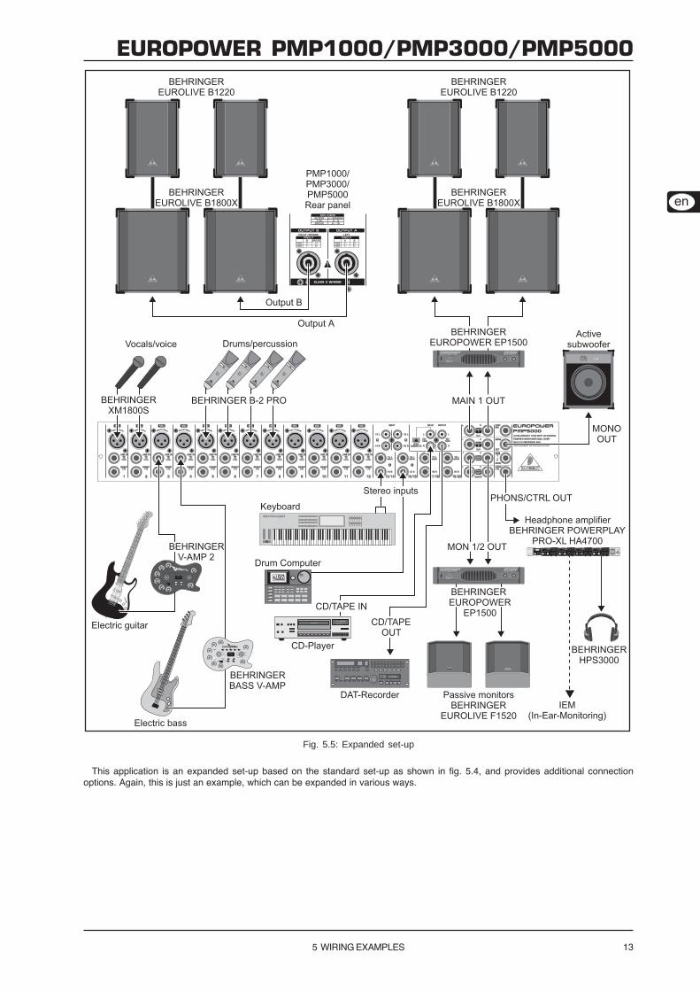
Fig. 5.5: Expanded set-up
This application is an expanded set-up based on the standard set-up as shown in fig. 5.4, and provides additional connection
options. Again, this is just an example, which can be expanded in various ways.

14
!"#$%$&!#'%(%)***+%(%,***+%(%-***
6 SPECIFICATIONS
6 SPECIFICATIONS
PMP1000 PMP3000 PMP5000
MICROPHONE INPUTS
Type
Mic E.I.N. (20 Hz - 20 kHz)
@ 0 ! source resistance
@ 50 ! source resistance
@ 150 ! source resistance
Gain
Max. input level
Impedance
Signal-to-noise ratio
Distortion (THD+N)
MONO LINE INPUTS
Type
Impedance
Max. input level
STEREO LINE INPUTS
Type
Impedance
Max. input level
EQUALIZER
Low
Mid 100 Hz - 8 kHz / ±15 dB
High
CD/TAPE INPUT
Type
Impedance
Max. input level
PRE AMP OUTPUTS
MAIN
Type
Impedance
Max. output level
MONITOR
Type
Impedance
Max. output level
STEREO OUTPUTS
Type -
Impedance -
Max. output level -
Type RCA
Impedance approx. 1 k!
Max. output level +21 dBu
MAIN MIX SYSTEM DATA
Noise
MAIN MIX @ -oo
Channel fader -oo
MAIN MIX @ 0 dB
Channel fader -oo
MAIN MIX @ 0 dB
Channel fader @ 0 dB
LOUDSPEAKER OUTPUTS
Type
Load impedance
MAIN L/R
MONITOR/MAIN MONO
MAIN MONO/MAIN MONO
BRIDGE
4 - 8 !
4 - 8 !
8 - 16 !
+21 dBu
compatible to NEUTRIK® SPEAKON
®
+21 dBu
-96 dB/-100 dB A-weighted
-86 dB/-89 dB A-weighted
-83 dB/-85 dB A-weighted
+21 dBu
1/4" TRS connectors, unbalanced
approx. 150 !, unbalanced
1/4" TRS connectors, unbalanced
approx. 150 !, unbalanced
+21 dBu
RCA
approx. 3.6 k!, balanced
+21 dBu
1/4" TRS connectors, unbalanced
approx. 150 !, unbalanced
80 Hz / ±15 dB
12 kHz / ±15 dB
2.5 kHz / ±15 dB
Frequency response
approx. 20 K!
+21 dBu
+22 dBu
+12 dBu @ +10 dB gain
approx. 2.6 k! balanced / 1.3 k! unbalanced
1/4" TRS connectors, unbalanced
> 3.6 k!
XLR, electronically balanced, discrete input circuit
+10 dB, +60 dB
109 dB / 112 dB A-weighted (0 dBu IN @ +10 dB gain)
0.002% / 0.0018% A-weighted
1/4" TS connectors, balanced
-134 dB / 136 dB A-weighted
-131.5 dB / 134 dB A-weighted
-129 dB / 131 dB A-weighted
< 10 Hz - > 200 kHz (-3 dB)
< 10 Hz - 155 kHz (-1 dB)
RCA
approx. 1 k!
-102 dB/-106 dB A-weighted
-88 dB/-91 dB A-weighted
-84 dB/-86 dB A-weighted
4 - 8 !

15
!"#$%$&!#'%(%)***+%(%,***+%(%-***
BEHRINGER is constantly striving to maintain the highest professional standards. As a result of these efforts, modifications may be made from time to time to existing products without prior notice.
Specifications and appearance may differ from those listed or illustrated.
6 SPECIFICATIONS
PMP1000 PMP3000 PMP5000
DSP
Converter
Dynamics D/A
Sampling rate
Delay Time
Signal run time (Line In à Line Out)
DISPLAY
Type 2 dual 7-segment LED
AMPLIFIER
8 ! per channel 90 W
4 ! per channel 130 W
8 ! 200 W
8 ! per channel 135 W
4 ! per channel 250 W
8 ! 500 W
POWER SUPPLY (EU/A)
Mains voltage 100 - 240 V~, 50 / 60 Hz
Power consumption 500 W
Fuse T 5 A H 250 V
Mains connector
POWER SUPPLY (UL)
Mains voltage 100 - 240 V~, 50 / 60 Hz
Power consumption 500 W
Fuse T 5 A H 250 V
Mains connector
POWER SUPPLY (J)
Mains voltage 100 - 240 V~, 50 / 60 Hz
Power consumption 500 W
Fuse T 5 A H 250 V
Mains connector
POWER SUPPLY (CN)
Mains voltage 100 - 240 V~, 50 / 60 Hz
Power consumption 500 W
Fuse T 5 A H 250 V
Mains connector
PHYSICAL/WEIGHT
4 7/8" x 15 3/8" x 16 3/4" 4 7/8" x 18 3/4" x 18 1/8" 4 7/8" x 23 1/2" x 19 1/2"
122 x 390 x 425 mm 122 x 476 x 460 mm 122 x 596 x 496 mm
15.435 lb. 23.815 lb. 28.665 lb.
8 kg 10.8 kg 13.3 kg
Standard IEC receptacle
220 V~, 50 Hz
1000 W
T 6,3 A H 250 V
1000 W
T 10 A H 250 V
Standard IEC receptacle
Standard IEC receptacle
100 V~, 50 / 60 Hz
1000 W
T 10 A H 250 V
90 dB
dual 7-segment LED
46.875 kHz
max. 5 s
24-Bit Delta-Sigma, 64/128-times oversampling
approx. 1.5 ms
Weight
Dimensions (H x W x D)
230 V~, 50 Hz
1000 W
T 6,3 A H 250 V
Standard IEC receptacle
120 V~, 60 Hz
OUTPUT POWER
RMS @ 1 % THD (sine wave), both channels driven:
215 W
450 W
600 W
Peak Power, bridged mode:
1200 W
RMS @ 1 % THD (sine wave), bridged mode:
900 W
Peak Power, both channels driven:
300 W

16
!"#$%$&!#'%(%)***+%(%,***+%(%-***
7 WARRANTY
Technical specifications and appearance subject to change without notice. The information contained herein is correct at the time of printing. The names
of companies, institutions or publications pictured or mentioned and their respective logos are registered trademarks of their respective owners. Their use
neither constitutes a claim of the trademarks by BEHRINGER nor affiliation of the trademark owners with BEHRINGER. BEHRINGER accepts no
liability for any loss which may be suffered by any person who relies either wholly or in part upon any description, photograph or statement contained
herein. Colours and specification may vary slightly from product. Products are sold through our authorised dealers only. Distributors and dealers are not
agents of BEHRINGER and have absolutely no authority to bind BEHRINGER by any express or implied undertaking or representation. No part of this
manual may be reproduced or transmitted in any form or by any means, electronic or mechanical, including photocopying and recording of any kind, for
any purpose, without the express written permission of BEHRINGER International GmbH. BEHRINGER® is a registered trademark.
ALL RIGHTS RESERVED. © 2006 BEHRINGER International GmbH,
Hanns-Martin-Schleyer-Str. 36-38, 47877 Willich-Münchheide II, Germany.
Tel. +49 2154 9206 0, Fax +49 2154 9206 4903
7 WARRANTY
§ 1 OTHER WARRANTY RIGHTS AND NATIONAL LAW
1. This warranty does not exclude or limit the buyer’s statutory
rights provided by national law, in particular, any such rights
against the seller that arise from a legally effective purchase
contract.
2. The warranty regulations mentioned herein are applicable
unless they constitute an infringement of national warranty law.
§ 2 ONLINE REGISTRATION
Please do remember to register your new BEHRINGER equipment
right after your purchase by visiting www.behringer.com
(alternatively www.behringer.de) and kindly read the terms andconditions of our warranty carefully.
Registering your purchase and equipment with us helps us
process your repair claims quicker and more efficiently.
Thank you for your cooperation!
§ 3 WARRANTY
1. BEHRINGER (BEHRINGER International GmbH including all
BEHRINGER subsidiaries listed on the enclosed page, except
BEHRINGER Japan) warrants the mechanical and electronic
components of this product to be free of defects in material and
workmanship for a period of one (1) year* from the original date
of purchase, in accordance with the warranty regulations
described below. If the product shows any defects within the
specified warranty period that are not excluded from this
warranty as described under § 5, BEHRINGER shall, at itsdiscretion, either replace or repair the product using suitable
new or reconditioned parts. In the case that other parts are used
which constitute an improvement, BEHRINGER may, at its
discretion, charge the customer for the additional cost of these
parts.
2. If the warranty claim proves to be justified, the product will be
returned to the user freight prepaid.
3. Warranty claims other than those indicated above are expressly
excluded.
§ 4 RETURN AUTHORIZATION NUMBER
1. To obtain warranty service, the buyer (or his authorized dealer)
must call BEHRINGER (see enclosed list) during normal business
hours BEFORE returning the product. All inquiries must be
accompanied by a description of the problem. BEHRINGER willthen issue a return authorization number.
2. Subsequently, the product must be returned in its original
shipping carton, together with the return authorization number to
the address indicated by BEHRINGER.
3. Shipments without freight prepaid will not be accepted.
§ 5 WARRANTY REGULATIONS
1. Warranty services will be furnished only if the product is
accompanied by a copy of the original retail dealer’s invoice.
Any product deemed eligible for repair or replacement under the
terms of this warranty will be repaired or replaced.
2. If the product needs to be modified or adapted in order tocomply with applicable technical or safety standards on a national
or local level, in any country which is not the country for which
the product was originally developed and manufactured, this
modification/adaptation shall not be considered a defect in
materials or workmanship. The warranty does not cover any
such modification/adaptation, irrespective of whether it was
carried out properly or not. Under the terms of this warranty,
BEHRINGER shall not be held responsible for any cost resulting
from such a modification/adaptation.
3. Free inspections and maintenance/repair work are expressly
excluded from this warranty, in particular, if caused by improper
handling of the product by the user. This also applies to defects
caused by normal wear and tear, in particular, of faders,crossfaders, potentiometers, keys/buttons, tubes, guitar strings,
illuminants and similar parts.
4. Damages/defects caused by the following conditions are not
covered by this warranty:
" improper handling, neglect or failure to operate the unit in
compliance with the instructions given in BEHRINGER user
or service manuals.
" connection or operation of the unit in any way that doesnot comply with the technical or safety regulations
applicable in the country where the product is used.
" damages/defects caused by force majeure or any other
condition that is beyond the control of BEHRINGER.
5. Any repair or opening of the unit carried out by unauthorized
personnel (user included) will void the warranty.
6. If an inspection of the product by BEHRINGER shows that the
defect in question is not covered by the warranty, the inspection
costs are payable by the customer.
7. Products which do not meet the terms of this warranty will be
repaired exclusively at the buyer’s expense. BEHRINGER willinform the buyer of any such circumstance. If the buyer fails to
submit a written repair order within 6 weeks after notification,
BEHRINGER will return the unit C.O.D. with a separate invoice
for freight and packing. Such costs will also be invoiced
separately when the buyer has sent in a written repair order.
§ 6 WARRANTY TRANSFERABILITY
This warranty is extended exclusively to the original buyer
(customer of retail dealer) and is not transferable to anyone
who may subsequently purchase this product. No other person
(retail dealer, etc.) shall be entitled to give any warranty promise
on behalf of BEHRINGER.
§ 7 CLAIM FOR DAMAGES
Failure of BEHRINGER to provide proper warranty service shall
not entitle the buyer to claim (consequential) damages. In noevent shall the liability of BEHRINGER exceed the invoiced value
of the product.
* Customers in the European Union please contact BEHRINGER
Germany Support for further details.

17
!"#$%$&!#'%(%)***+%(%,***+%(%-***
FEDERAL COMMUNICATIONS COMMISSION
COMPLIANCE INFORMATION
Responsible party name: BEHRINGER USA, Inc.
Address: 18912 North Creek Parkway, Suite 200
Bothell, WA 98011, USA
Phone/Fax No.: Phone: +1 425 672 0816,
Fax: +1 425 673 7647
hereby declares that the product
!"#$%$&!#' %(%)***+,***+-***
complies with the FCC rules as mentioned in the following paragraph:
This equipment has been tested and found to comply with the limits for a Class B digital device, pursuant to part 15
of the FCC Rules. These limits are designed to provide reasonable protection against harmful interference in a
residential installation. This equipment generates, uses and can radiate radio frequency energy and, if not installed
and used in accordance with the instructions, may cause harmful interference to radio communications. However,
there is no guarantee that interference will not occur in a particular installation. If this equipment does cause harmful
interference to radio or television reception, which can be determined by turning the equipment off and on, the user
is encouraged to try to correct the interference by one or more of the following measures:
" Reorient or relocate the receiving antenna.
" Increase the separation between the equipment and receiver.
" Connect the equipment into an outlet on a circuit different from that to which the receiver
is connected.
" Consult the dealer or an experienced radio/TV technician for help.
This device complies with Part 15 of the FCC rules. Operation is subject to the following two conditions: (1) this
device may not cause harmful interference, and (2) this device must accept any interference received, including
interference that may cause undesired operation.
Important information:
Changes or modifications to the equipment not expressly approved by BEHRINGER USA can
void the user’s authority to use the equipment.


![P ] o & o o ]](https://static.fdocuments.in/doc/165x107/62ad94ec58e4b82eb5584ac8/p-o-amp-o-o-.jpg)


![s o P µ o } ] v À o P î ì í õ ~ À ] } v ì î X u î ì í õ o ...€¦ · s o P P µ í r s o P P µ À ] v l o ] P } v o v o u u v P ] À µ ( } Z Z À X o ] } P } v](https://static.fdocuments.in/doc/165x107/6021caaeef03fc38e63bf879/s-o-p-o-v-o-p-v-x-u-o-s-o-p.jpg)

