Data Loggers Overview - LSI LASTEM · 2017-04-27 · Data Loggers Assembly division Data Loggers...
40
Data Loggers Overview Milano ITALY General Catalog data loggers 1 2 3 4 >> DATA LOGGERS 4 5 6 7 8 2 3 4 |||| MW9005-ENG 03/2016 Components 2
Transcript of Data Loggers Overview - LSI LASTEM · 2017-04-27 · Data Loggers Assembly division Data Loggers...
DataLoggersOverview
MilanoITALY
Ge
ne
ral C
ata
log
data loggers
1
2
3
4
5
6
7
8
>> D
ATA
LO
GG
ER
S
1
2
3
4
5
6
7
8
1
2
3
4
|||| MW9005-ENG 03/2016
Components
2
LSI LASTEM S.r.l. 20090 Settala (MI) Italy tel: +39 02 954141 fax: +39 02 95770594 e-mail: [email protected] |
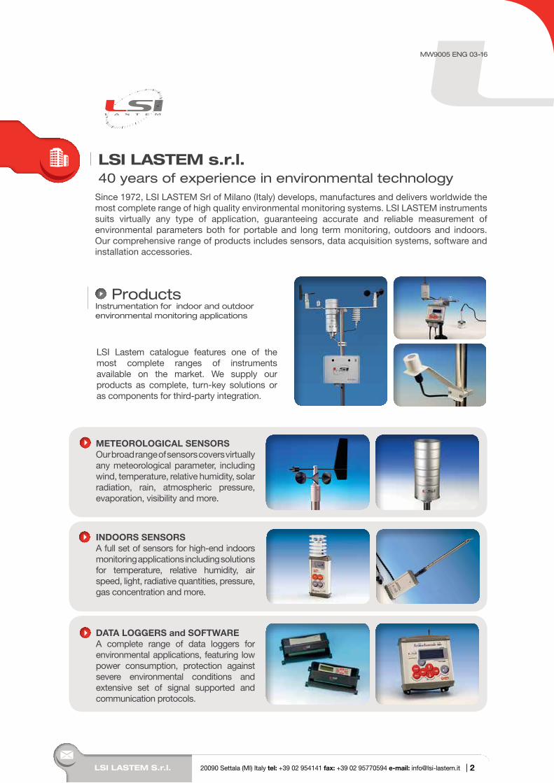
METEOROLOGICAL SENSORS Our broad range of sensors covers virtually any meteorological parameter, including wind, temperature, relative humidity, solar radiation, rain, atmospheric pressure, evaporation, visibility and more.
ProductsInstrumentation for indoor and outdoor environmental monitoring applications
LSI Lastem catalogue features one of the most complete ranges of instruments available on the market. We supply our products as complete, turn-key solutions or as components for third-party integration.
Since 1972, LSI LASTEM Srl of Milano (Italy) develops, manufactures and delivers worldwide the most complete range of high quality environmental monitoring systems. LSI LASTEM instruments suits virtually any type of application, guaranteeing accurate and reliable measurement of environmental parameters both for portable and long term monitoring, outdoors and indoors. Our comprehensive range of products includes sensors, data acquisition systems, software and installation accessories.
LSI LASTEM s.r.l.40 years of experience in environmental technology
INDOORS SENSORSA full set of sensors for high-end indoors monitoring applications including solutions for temperature, relative humidity, air speed, light, radiative quantities, pressure, gas concentration and more.
DATA LOGGERS and SOFTWAREA complete range of data loggers for environmental applications, featuring low power consumption, protection against severe environmental conditions and extensive set of signal supported and communication protocols.
MW9005 ENG 03-16
2
LSI L
AS
TEM
S.r.
l.
Indoor Environmental QualitySince his inception, indoor environmental assessment has been LSI Lastem’s core business. Over the years, we implemented the most complete range of systems to measure the critical quantities defining health and comfort of building occupants.
Heat stress and thermal comfort State-of-the-art systems for the measurement of thermal comfort and heat/cold stress in health and safety applications according to relevant ISO standards. Over the years this application has become a true LSI LASTEM’s specialty.
HVACComplete solutions for thermal comfort and indoor air quality monitoring in order to regulate HVAC (Heating, Ventilation Air Conditioning) systems performances and attain a better thermal sensation with optimal energy expenditures.
Buildings assessment/Wall insulationComplete systems for testing building environmental performances as function of energy saving capacity and related environmental comfort (Green Building Rating Tools) - including wall thermal transmittance, thermal comfort, indoor air quality and ventilation, light controls.
Controlled Atmosphere Processing EnvironmentsMonitoring of ambient temperature, relative humidity, air speed, pressure, IAQ and other parameters relevant for optimal storing and processing purposes in clean rooms, white chambers, laboratories, warehouses, caves and green houses.
Museums and heritagePracticing on Italy’s immense cultural and artistic heritage and in cooperation with the most renowned restoration institutes, LSI Lastem has implemented monitoring solutions for the critical environmental and chemical parameters affecting conservation of artworks in museums, archeological sites and natural caves.
SystemsLSI Lastem knowledge and expertise, the result of 40 years of business in the environmental market, has helped customers put together an incredible number of application-specific monitoring solutions.
INDOORS APPLICATIONS
|
Page
3
MW
9005
-ENG

Air Quality MonitoringMeteorological measurements for the analysis of the atmosphere dynamics and data correlation for air quality networks, stack emissions and gas analyzers systems.
ENVIRONMENT AND POLLUTION
METEOROLOGICAL APPLICATIONS
AWS and Synoptic Meteorological systemsComplete surface weather observation systems according to WMO standards for general or specific meteorological observations, operating individually or in networks.
Compost and biofiltersSystems to monitor the compost maturation process and bio-filtration activity. We provide solutions for temperature, oxygen and water content monitoring, for on-line (wireless or cabled) and portable applications.
Landfills and waste plants monitoring Monitoring of meteorological parameters in environmental-hazardous plants such as landfills and waste treatment plants. Solutions for odours dynamics, rain quantity and deepwater level&quality.
Road and transportation monitoring systems Meteorological measurements systems for roads, railroads, seaports and airports-including specific parameters such as wind, visibility, precipitation intensity and type, road-surface conditions and present weather.
Hydrology systems Meteorological systems to control water both as a resource and as a hazard in hydrological networks and water-basin management – including measures of rain intensity, level and quality of water and snow.
AgrometeorologyClimate is the single most important factor for crops growth and health. We offer a complete range of application-specific monitoring for leaf wetness, evapotranspiration, soil water content and photosynthetic-active radiation.
Wind energyFrom site assessment to wind turbine control, our complete meteorological catalogue with its full range of anemometers and data logger, gives wind energy professionals one of the most complete arrays of solutions available on the market.
Solar energyAs Italy evolved into a premium solar energy market, we became the preferred choice for plant owners, EPC contractors and monitoring systems producers as we developed a unique knowledge of the application to go along with our meteorological and radiometric know-how.
|
Page
4
www.lsi-lastem.com
LSI L
AS
TEM
S.r.
l. -
Sto
ry
The LSI LASTEM Story40 years of experience in environmental technology
1972 - Laboratori di Strumentazione Industriale (LSI) Spa is organized in Milano by former members of a previously existing electronic research company (LRE) and begins the production of electrical thermometers. Soon afterwards, the company adds systems to measure relative humidity through the psychrometric method and hot-wire anemometers to his portfolio.
1975 - The company introduces graphic recorders for the online printing of the measured values and a line of converters for the connection of sensors to industrial systems. In just a short time, the range of products and measured quantities is remarkably increased with the introduction of sensors for the measurement of different types of temperature radiant, contact and of liquids, along with luxmetric sensors and hygrometers.
1979 - Introducing the LASTEM logo, the company begins the production and distribution of his line of sensors and data acquisition systems specific for meteorological applications. LASTEM Srl is now operative.
1980 - LSI is the first company in Italy to produce instruments for the measurement and storage of the thermal environments parameters requested in the health and safety regulations in working environments.
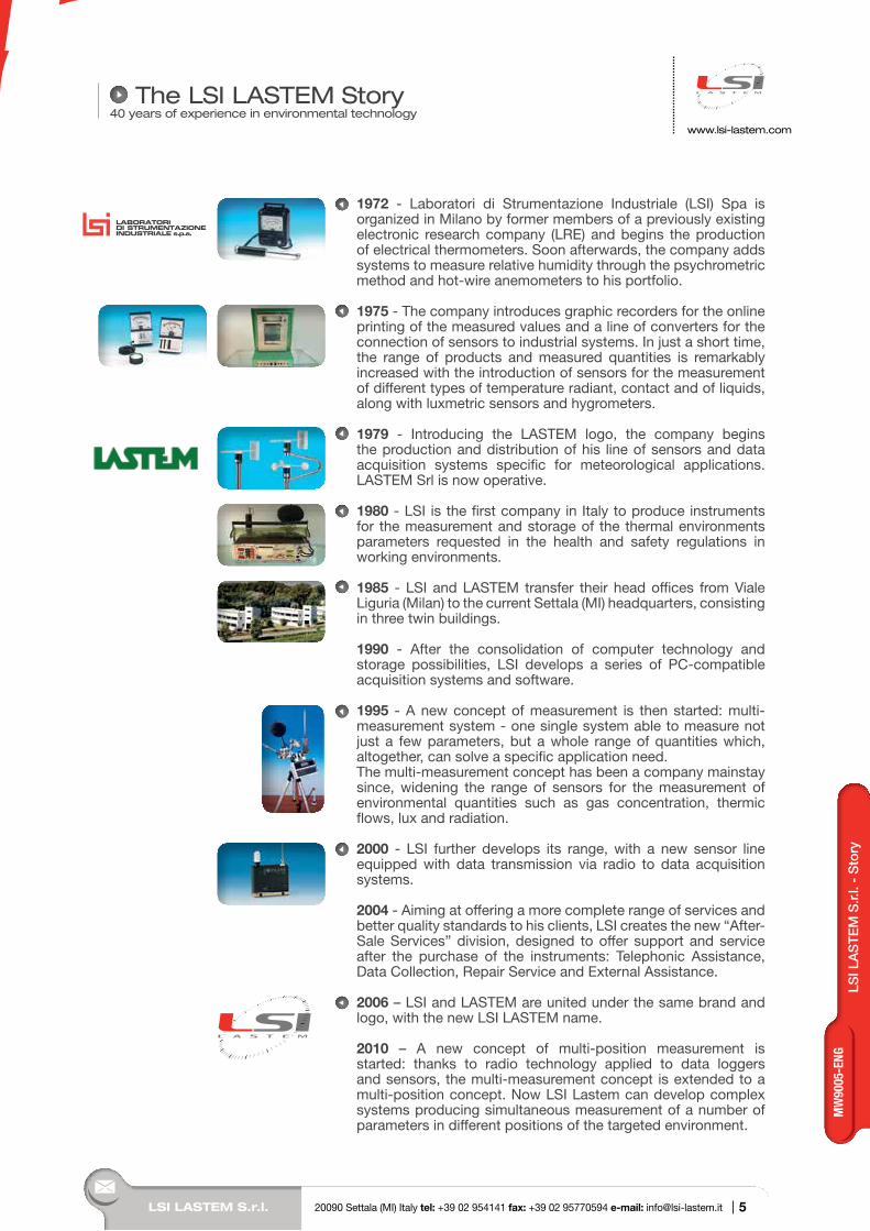
1985 - LSI and LASTEM transfer their head offices from Viale Liguria (Milan) to the current Settala (MI) headquarters, consisting in three twin buildings.
1990 - After the consolidation of computer technology and storage possibilities, LSI develops a series of PC-compatible acquisition systems and software.
1995 - A new concept of measurement is then started: multi-measurement system - one single system able to measure not just a few parameters, but a whole range of quantities which, altogether, can solve a specific application need. The multi-measurement concept has been a company mainstay since, widening the range of sensors for the measurement of environmental quantities such as gas concentration, thermic flows, lux and radiation.
2000 - LSI further develops its range, with a new sensor line equipped with data transmission via radio to data acquisition systems.
2004 - Aiming at offering a more complete range of services and better quality standards to his clients, LSI creates the new “After-Sale Services” division, designed to offer support and service after the purchase of the instruments: Telephonic Assistance, Data Collection, Repair Service and External Assistance.
2006 – LSI and LASTEM are united under the same brand and logo, with the new LSI LASTEM name.
2010 – A new concept of multi-position measurement is started: thanks to radio technology applied to data loggers and sensors, the multi-measurement concept is extended to a multi-position concept. Now LSI Lastem can develop complex systems producing simultaneous measurement of a number of parameters in different positions of the targeted environment.
LSI LASTEM S.r.l. 20090 Settala (MI) Italy tel: +39 02 954141 fax: +39 02 95770594 e-mail: [email protected] | 5
MW
9005
-ENG
www.lsi-lastem.com
LSI LASTEM S.r.l. 20090 Settala (MI) Italy tel: +39 02 954141 fax: +39 02 95770594 e-mail: [email protected] |
LSI LASTEM HeadquartersSettala (MI) ITALY
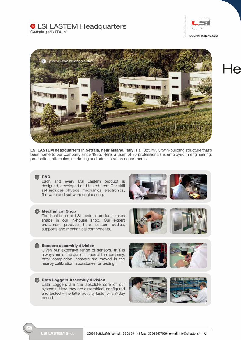
R&DEach and every LSI Lastem product is designed, developed and tested here. Our skill set includes physics, mechanics, electronics, firmware and software engineering.
Mechanical ShopThe backbone of LSI Lastem products takes shape in our in-house shop. Our expert craftsmen produce here sensor bodies, supports and mechanical components.
Sensors assembly divisionGiven our extensive range of sensors, this is always one of the busiest areas of the company. After completion, sensors are moved in the nearby calibration laboratories for testing.
Data Loggers Assembly divisionData Loggers are the absolute core of our systems. Here they are assembled, configured and tested – the latter activity lasts for a 7-day period.
LSI LASTEM headquarters in Settala, near Milano, Italy is a 1325 m2, 3 twin-building structure that’s been home to our company since 1985. Here, a team of 30 professionals is employed in engineering, production, aftersales, marketing and administration departments.
| photo | 3 twin-building structure
6
HeadquartersHe
7
MW
9005
-ENG
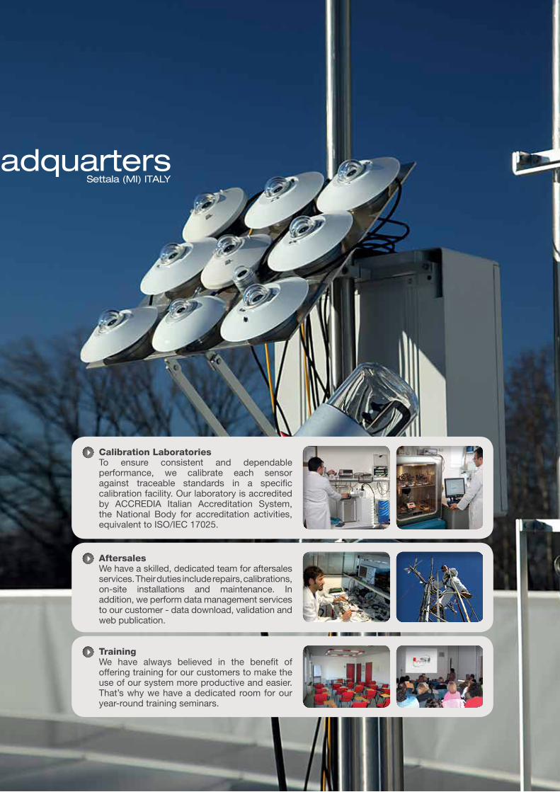
Calibration LaboratoriesTo ensure consistent and dependable performance, we calibrate each sensor against traceable standards in a specific calibration facility. Our laboratory is accredited by ACCREDIA Italian Accreditation System, the National Body for accreditation activities, equivalent to ISO/IEC 17025.
AftersalesWe have a skilled, dedicated team for aftersales services. Their duties include repairs, calibrations, on-site installations and maintenance. In addition, we perform data management services to our customer - data download, validation and web publication.
TrainingWe have always believed in the benefit of offering training for our customers to make the use of our system more productive and easier. That’s why we have a dedicated room for our year-round training seminars.
HeadquartersSettala (MI) ITALY
He
LSI LASTEM designs and manufactures a wide range of data loggers for environmental applications. With very low power consumption, expanded signal capacity and protections against severe environmental conditions, LSI LASTEM data loggers are the ideal solution for measurements in meteorological, air quality, indoor and outdoor environmental monitoring applications. The different features of LSI LASTEM instruments suits virtually any environmental monitoring procedure, guaranteeing accurate and reliable monitoring of physical parameters both for portable and continuous application, outdoors and indoors. LSI LASTEM data loggers can send and receive data to each other, allowing for MASTER/SLAVE or NETWORK architectures and design of multi-measurement and multi-positions monitoring systems.Data logger flexibility and input range makes the use of third party sensors and transducers just as easy as the ones from LSI LASTEM production (see Indoor sensors, Meteorological sensors catalogues).
Our Data logger series includes three main families: M-Log Mini Data logger E-Log Environmental Data logger R-Log Radio Data logger X-Log Expert Data Logger
Order numb. Pag.
M-Log ELO007 9
ELO008
ELO009
ELO010
E-Log ELO105 13
ELO305
ELO310
ELO515
R-Log ELR510 17
ELR515
ELR517
Calculated Quantities 23
X-Log XLO001 24
Order numb. Pag.
Accessories Supports 29
Power supply Devices
30
Batteries 31
RS232 cables USB interface, Bluetooth
31
RS485, TCP/IP Modules
32
Reed relay 32
Inputs expansion modules for X-Log
33
GSM/GPRS UMTS router
34
Input electrical protection boards
35
Long distance VHF radio
36
Solar panel 37
Carrying cases 37
Shockproof cases 38
IP65 boxes 39
Index
Data LoggersGeneral catalogue
LSI LASTEM S.r.l. 20090 Settala (MI) Italy tel: +39 02 954141 fax: +39 02 95770594 e-mail: [email protected] | 8
www.lsi-lastem.com
InputsN. 4 (8 single-ended) inputs for analogue signals (voltage, current and resistance).N. 1 digital input. It can be configured for frequency or digital on/off signals.N.1 input for RS232 sensors
Models with mini-Din inputs and sensors self-recognition feature and models with terminal input board are available
Derived environmental and mathematical calculationsM-Log has an internal library of derived environmental quantities. These calculated quantities can use inputs from monitoring measures, user-defined constants and other derived quantities.This library also includes mathematical calculations (see Calculated Quantities - p. 22)
Sampling rate Programmable for each sensor (1 sec -12 hrs). M-Log manages up to n.4 channels from sensors and n.16 derived quantities in 1 sec.
Data storage M-Log stores statistical elaborations with time bases from 1 sec. to 24 hrs:- instant values- arithmetical average, minimum, maximum, standard deviation- totalization and integration time measurements- wind elaborations: resulting/prevailing direction, resulting speed, direction standard deviation (sigma- theta), calm percentage.Memory structure is circular.
Output actuation at event/timeM-Log (ELO007-008) has three digital outputs to power up external systems or alarm devices. Outputs are activated according to user-defined actuation logics.- Greater/less than, within a range;- Wind alarm;- Alarm for beginning of precipitations;- Flood Alarm;- Scheduled event;- Snow level alarm;- Error state of the unit.
Sensors power supply actuationM-Log can feed sensors requiring power supply for their operation, with user-defined warm-up time.
BatteryM-Log comes with an internal (2 Ah, 4.2 V) Lithium rechargeable battery. For long-term operation, additional batteries are normally included in ELF enclosures (see Accessories). LSI-LASTEM supplies 2-15-40 Ah rechargeable battery packs and 1,5-V, D-shaped disposable battery packs. Batteries can be recharged using main power supply or solar panels.
Power supplyM-Log runs at 12 Vdc input voltage power supply and features an extremely low power consumption (< 4 mW).
Serial ports for data communicationM-Log is equipped with two RS232 serial ports. Both of them can be used for local or remote communication for data download or real-time update of instantaneous and diagnostic values.Serial Port n. 2 can also be used to connect sensors with RS232 output (see “Protocols” table).
M-Log – Mini Data Logger
Main Features
Highlights
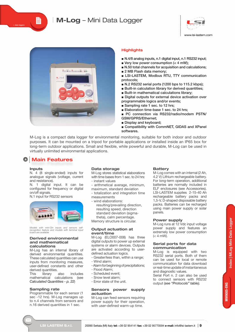
N.4/8 analog inputs, n.1 digital input, n.1 RS232 input; Very low power consumption (< 4 mW); N.50 total channels for acquisition and calculations; 2 MB Flash data memory; LSI-LASTEM, Modbus RTU, TTY communication protocols; N.2 RS232 serial ports (1200 bps to 115.2 kbps); Built-in calculation library for derived quantities; Built-in mathematical calculations library; Digital outputs for external device activation over programmable logics and/or events; Sampling rate 1 sec. to 12 hrs; Elaboration time-base 1 sec. to 24 hrs; PC connection via RS232/radio/modem PSTN/GSM/GPRS/Ethernet; Display and keyboard; Compatibility with CommNET, GIDAS and XPanel softwares.
M-Log is a compact data logger for environmental monitoring, suitable for both indoor and outdoor purposes. It can be mounted on a tripod for portable applications or installed inside an IP65 box for long-term outdoor applications. Small and flexible, while powerful and durable, M-Log can be used in virtually unlimited environmental applications.
> data loggers
Tem
per
atur
a d
ell’a
riaIn
dex
| M
Log
Min
i Dat
a Lo
gger
LSI LASTEM S.r.l. 20090 Settala (MI) Italy tel: +39 02 954141 fax: +39 02 95770594 e-mail: [email protected] | 9
MW
9005
-ENG
LSI LASTEM S.r.l. 20090 Settala (MI) Italy tel: +39 02 954141 fax: +39 02 95770594 e-mail: [email protected] |
www.lsi-lastem.com
Direct connection to PCM-Log can be directly connected to a PC with the following interfaces:- USB, using included adapter;- RS485 line drivers: distances up to 1 km, using DEA504 converter;- Ethernet, using DEA550 converter (ELO007 features a built-in RJ45 port);- Bluetooth, using DEA300 adapter.
Remote connection to PCM-Log can be remotely connected to a PC with the following interfaces:- Telephone network: GSM and GPRS: GSM/GPRS modem;-Long distances UHF radio communication;CommNetEG software can help managing both direct and remote connections with automatic/scheduled communications.
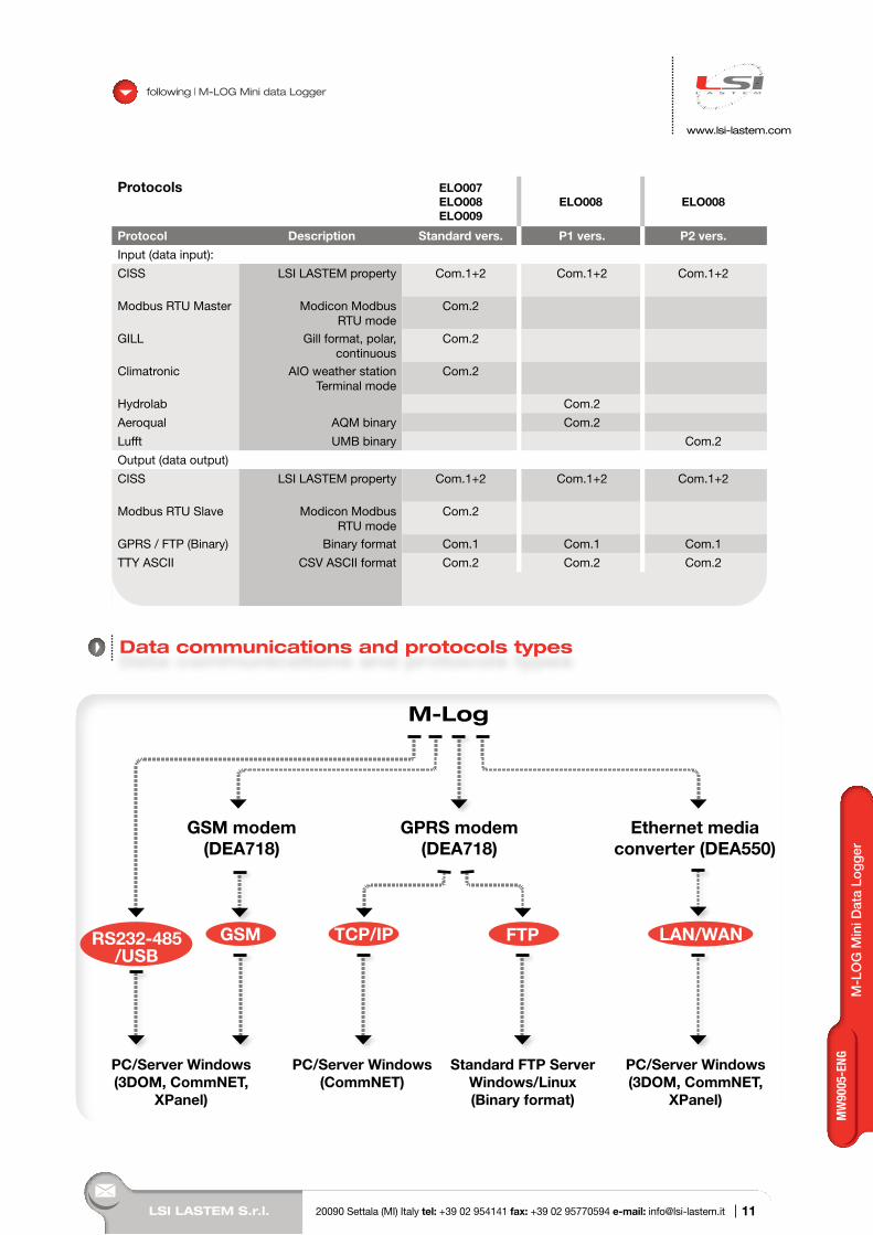
Data communication in ASCII format using GPRS/FTP and TCP/IP protocolsM-Log can send instant or statistical data using programmable scheduled time in spontaneous mode by GPRS modem and FTP protocol or by TCP/IP converter (over LAN or WAN). See “Data communications and protocols types” scheme.
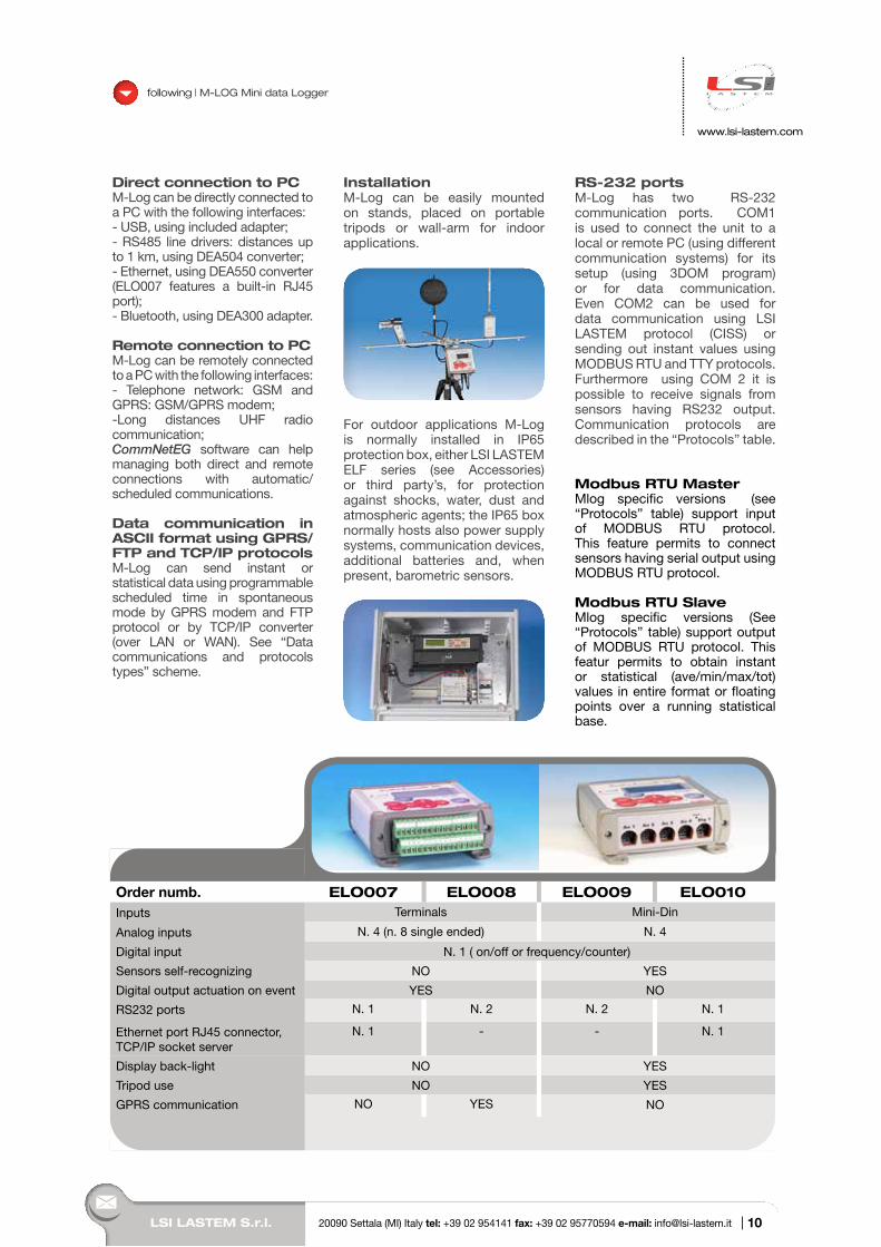
InstallationM-Log can be easily mounted on stands, placed on portable tripods or wall-arm for indoor applications.
For outdoor applications M-Log is normally installed in IP65 protection box, either LSI LASTEM ELF series (see Accessories) or third party’s, for protection against shocks, water, dust and atmospheric agents; the IP65 box normally hosts also power supply systems, communication devices, additional batteries and, when present, barometric sensors.
RS-232 portsM-Log has two RS-232 communication ports. COM1 is used to connect the unit to a local or remote PC (using different communication systems) for its setup (using 3DOM program) or for data communication. Even COM2 can be used for data communication using LSI LASTEM protocol (CISS) or sending out instant values using MODBUS RTU and TTY protocols. Furthermore using COM 2 it is possible to receive signals from sensors having RS232 output. Communication protocols are described in the “Protocols” table.
Modbus RTU MasterMlog specific versions (see “Protocols” table) support input of MODBUS RTU protocol. This feature permits to connect sensors having serial output using MODBUS RTU protocol.
Modbus RTU SlaveMlog specific versions (See “Protocols” table) support output of MODBUS RTU protocol. This featur permits to obtain instant or statistical (ave/min/max/tot) values in entire format or floating points over a running statistical base.
following | M-LOG Mini data Logger
Order numb. ELO007 ELO008 ELO009 ELO010Inputs Terminals Mini-Din
Analog inputs N. 4 (n. 8 single ended) N. 4
Digital input N. 1 ( on/off or frequency/counter)
Sensors self-recognizing NO YES
Digital output actuation on event YES NO
RS232 ports N. 1 N. 2 N. 2 N. 1
Ethernet port RJ45 connector, TCP/IP socket server
N. 1 - - N. 1
Display back-light NO YES
Tripod use NO YES
GPRS communication NO YES NO
10
M-L
OG
Min
i Dat
a Lo
gger
LSI LASTEM S.r.l. 20090 Settala (MI) Italy tel: +39 02 954141 fax: +39 02 95770594 e-mail: [email protected] |
following | M-LOG Mini data Logger
www.lsi-lastem.com
Protocols ELO007ELO008ELO009
ELO008 ELO008
Protocol Description Standard vers. P1 vers. P2 vers.
Input (data input):
CISS LSI LASTEM property Com.1+2 Com.1+2 Com.1+2
Modbus RTU Master Modicon Modbus RTU mode
Com.2
GILL Gill format, polar, continuous
Com.2
Climatronic AIO weather station Terminal mode
Com.2
Hydrolab Com.2
Aeroqual AQM binary Com.2
Lufft UMB binary Com.2
Output (data output)
CISS LSI LASTEM property Com.1+2 Com.1+2 Com.1+2
Modbus RTU Slave Modicon Modbus RTU mode
Com.2
GPRS / FTP (Binary) Binary format Com.1 Com.1 Com.1
TTY ASCII CSV ASCII format Com.2 Com.2 Com.2
Data communications and protocols types
11
MW
9005
-ENG
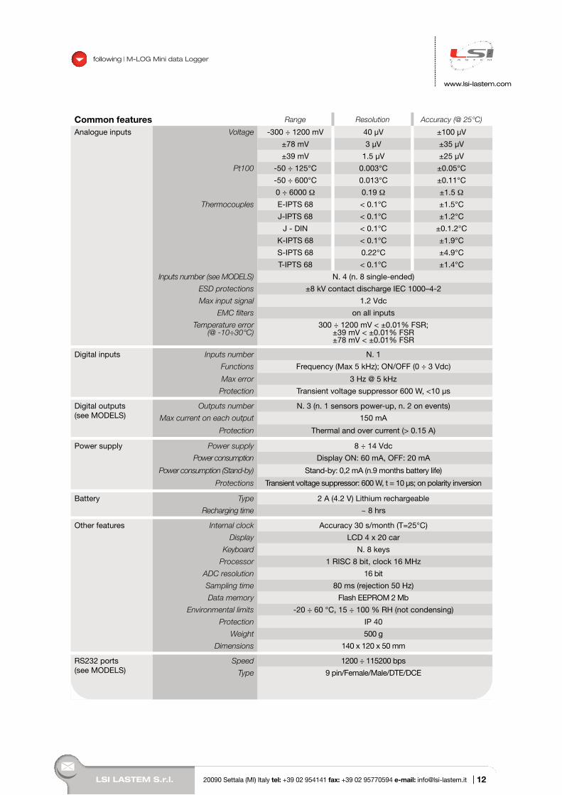
Common features Range Resolution Accuracy (@ 25°C)
Analogue inputs Voltage -300 ÷ 1200 mV 40 µV ±100 µV
±78 mV 3 µV ±35 µV
±39 mV 1.5 µV ±25 µV
Pt100 -50 ÷ 125°C 0.003°C ±0.05°C
-50 ÷ 600°C 0.013°C ±0.11°C
0 ÷ 6000 Ω 0.19 Ω ±1.5 Ω
Thermocouples E-IPTS 68 < 0.1°C ±1.5°C
J-IPTS 68 < 0.1°C ±1.2°C
J - DIN < 0.1°C ±0.1.2°C
K-IPTS 68 < 0.1°C ±1.9°C
S-IPTS 68 0.22°C ±4.9°C
T-IPTS 68 < 0.1°C ±1.4°C
Inputs number (see MODELS) N. 4 (n. 8 single-ended)
ESD protections ±8 kV contact discharge IEC 1000–4-2
Max input signal 1.2 Vdc
EMC filters on all inputs
Temperature error (@ -10÷30°C)
300 ÷ 1200 mV < ±0.01% FSR;±39 mV < ±0.01% FSR±78 mV < ±0.01% FSR
Digital inputs Inputs number N. 1
Functions Frequency (Max 5 kHz); ON/OFF (0 ÷ 3 Vdc)
Max error 3 Hz @ 5 kHz
Protection Transient voltage suppressor 600 W, <10 µs
Digital outputs(see MODELS)
Outputs number N. 3 (n. 1 sensors power-up, n. 2 on events)
Max current on each output 150 mA
Protection Thermal and over current (> 0.15 A)
Power supply Power supply 8 ÷ 14 Vdc
Power consumption Display ON: 60 mA, OFF: 20 mA
Power consumption (Stand-by) Stand-by: 0,2 mA (n.9 months battery life)
Protections Transient voltage suppressor: 600 W, t = 10 µs; on polarity inversion
Battery Type 2 A (4.2 V) Lithium rechargeable
Recharging time ~ 8 hrs
Other features Internal clock Accuracy 30 s/month (T=25°C)
Display LCD 4 x 20 car
Keyboard N. 8 keys
Processor 1 RISC 8 bit, clock 16 MHz
ADC resolution 16 bit
Sampling time 80 ms (rejection 50 Hz)
Data memory Flash EEPROM 2 Mb
Environmental limits -20 ÷ 60 °C, 15 ÷ 100 % RH (not condensing)
Protection IP 40
Weight 500 g
Dimensions 140 x 120 x 50 mm
RS232 ports(see MODELS)
Speed 1200 ÷ 115200 bps
Type 9 pin/Female/Male/DTE/DCE
www.lsi-lastem.com
following | M-LOG Mini data Logger
LSI LASTEM S.r.l. 20090 Settala (MI) Italy tel: +39 02 954141 fax: +39 02 95770594 e-mail: [email protected] | 12
LSI LASTEM S.r.l. 20090 Settala (MI) Italy tel: +39 02 954141 fax: +39 02 95770594 e-mail: [email protected] |
www.lsi-lastem.com
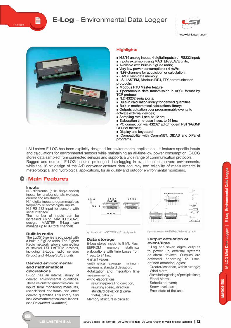
E-Log – Environmental Data Logger
InputsN.8 differential (n.16 single-ended) inputs for analog signals (voltage, current and resistance).N.4 digital inputs programmable as frequency or on/off digital inputsN.1 RS 232 input for sensors with serial interface.The number of inputs can be increased using MASTER/SLAVE design. MASTER E-Log can manage up to 99 total channels.
Built-in radioThe ELO515 series is equipped with a built-in ZigBee radio. The Zigbee Radio network allows connecting of several LSI LASTEM devices, including E-Logs, radio sensors (S-Log) and R-Log-SLAVE units.
Derived environmental and mathematical calculationsE-Log has an internal library of derived environmental quantities. These calculated quantities can use inputs from monitoring measures, user-defined constants and other derived quantities This library also includes mathematical calculations. (see Calculated Quantities)
M A S T E RR S 2 3 2
E L A 1 2 1
E L A 1 1 0
E - L o g 1
CO
M 1
CO
M 2
CO
M 1
CO
M 2
E - L o g 2
Inputs extension: MASTER/SLAVE units by cable
Data storageE-Log stores inside its 8 Mb Flash EEPROM memory statistical elaborations with time bases from 1 sec. to 24 hrs:-instant values;-arithmetical average, minimum, maximum, standard deviation;-totalization and integration time measurements;-wind elaborations: resulting/prevailing direction, resulting speed, direction standard deviation (sigma- theta), calm %.Memory structure is circular.
Inputs extension: MASTER/SLAVE units by radio
Output actuation at event/timeE-Log has seven digital outputs to power up external systems or alarm devices. Outputs are activated according to user-defined actuation logics:- Greater/less than, within a range;- Wind alarm;- Alarm for beginning of precipitations;- Flood Alarm;- Scheduled event;- Snow level alarm;- Error state of the unit.
Main Features
Highlights
N.8/16 analog inputs, 4 digital inputs, n.1 RS232 input; Inputs extension using MASTER/SLAVE units; Available with built-in ZigBee radio; Very low power consumption (< 4 mW); N.99 channels for acquisition or calculation; 8 MB Flash data memory; LSI-LASTEM, Modbus RTU, TTY communication protocols; Modbus RTU Master feature; Spontaneous data transmission in ASCII format by TCP protocol; N.2 RS232 serial ports; Built-in calculation library for derived quantities; Built-in mathematical calculations library; Outputs actuation over programmable events to activate external devices; Sampling rate 1 sec. to 12 hrs; Elaboration time-base 1 sec. to 24 hrs; PC connection via RS232/radio/modem PSTN/GSM/GPRS/Ethernet; Display and keyboard; Compatibility with CommNET, GIDAS and XPanel programs.
LSI Lastem E-LOG has been explicitly designed for environmental applications. It features specific inputs and calculations for environmental sensors while maintaining an all-time-low power consumption. E-LOG stores data sampled from connected sensors and supports a wide range of communication protocols. Rugged and durable, E-LOG ensures prolonged data-logging in even the most severe environments, while the 16-bit design of the A/D converter ensures data accuracy and reliability of measurements in meteorological and hydrological applications, for air quality and outdoor environmental monitoring.
> data loggers
M-L
OG
Min
i Dat
a Lo
gger
|
E-L
og E
nviro
nmen
tal D
ata
Logg
er
13
MW
9005
-ENG
LSI LASTEM S.r.l. 20090 Settala (MI) Italy tel: +39 02 954141 fax: +39 02 95770594 e-mail: [email protected] |
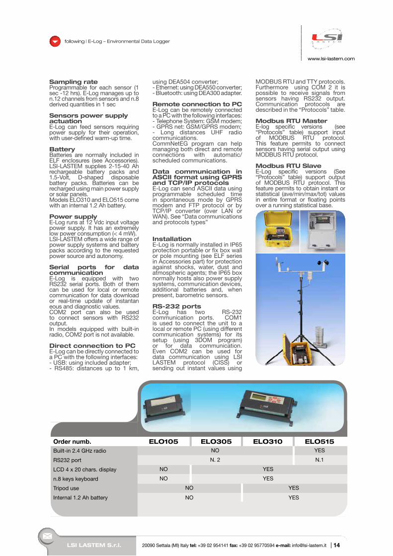
Sampling rateProgrammable for each sensor (1 sec -12 hrs). E-Log manages up to n.12 channels from sensors and n.8 derived quantities in 1 sec
Sensors power supply actuationE-Log can feed sensors requiring power supply for their operation, with user-defined warm-up time.
BatteryBatteries are normally included in ELF enclosures (see Accessories). LSI-LASTEM supplies 2-15-40 Ah rechargeable battery packs and 1.5-Volt, D-shaped disposable battery packs. Batteries can be recharged using main power supply or solar panels. Models ELO310 and ELO515 come with an internal 1.2 Ah battery.
Power supplyE-Log runs at 12 Vdc input voltage power supply. It has an extremely low power consumption (< 4 mW).LSI-LASTEM offers a wide range of power supply systems and battery packs according to the requested power source and autonomy.
Serial ports for data communicationE-Log is equipped with two RS232 serial ports. Both of them can be used for local or remote communication for data download or real-time update of instantan eous and diagnostic values.COM2 port can also be used to connect sensors with RS232 output.In models equipped with built-in radio, COM2 port is not available.
Direct connection to PCE-Log can be directly connected to a PC with the following interfaces:- USB: using included adapter;- RS485: distances up to 1 km,
using DEA504 converter;- Ethernet: using DEA550 converter; - Bluetooth: using DEA300 adapter.
Remote connection to PCE-Log can be remotely connected to a PC with the following interfaces:- Telephone System: GSM modem;- GPRS net: GSM/GPRS modem;- Long distances UHF radio communications.CommNetEG program can help managing both direct and remote connections with automatic/scheduled communications.
Data communication in ASCII format using GPRS and TCP/IP protocolsE-Log can send ASCII data using programmable scheduled time in spontaneous mode by GPRS modem and FTP protocol or by TCP/IP converter (over LAN or WAN). See “Data communications and protocols types”
InstallationE-Log is normally installed in IP65 protection portable or fix box wall or pole mounting (see ELF series in Accessories part) for protection against shocks, water, dust and atmospheric agents; the IP65 box normally hosts also power supply systems, communication devices, additional batteries and, when present, barometric sensors.
RS-232 portsE-Log has two RS-232 communication ports. COM1 is used to connect the unit to a local or remote PC (using different communication systems) for its setup (using 3DOM program) or for data communication. Even COM2 can be used for data communication using LSI LASTEM protocol (CISS) or sending out instant values using
MODBUS RTU and TTY protocols. Furthermore using COM 2 it is possible to receive signals from sensors having RS232 output. Communication protocols are described in the “Protocols” table.
Modbus RTU MasterE-log specific versions (see “Protocols” table) support input of MODBUS RTU protocol. This feature permits to connect sensors having serial output using MODBUS RTU protocol.
Modbus RTU SlaveE-Log specific versions (See “Protocols” table) support output of MODBUS RTU protocol. This feature permits to obtain instant or statistical (ave/min/max/tot) values in entire format or floating points over a running statistical base.
www.lsi-lastem.com
following | E-Log – Environmental Data Logger
Order numb. ELO105 ELO305 ELO310 ELO515Built-in 2.4 GHz radio NO YES
RS232 port N. 2 N.1
LCD 4 x 20 chars. display NO YES
n.8 keys keyboard NO YES
Tripod use NO YES
Internal 1.2 Ah battery NO YES
14
LSI LASTEM S.r.l. 20090 Settala (MI) Italy tel: +39 02 954141 fax: +39 02 95770594 e-mail: [email protected] |
E
-Log
Env
ironm
enta
l Dat
a Lo
gger
www.lsi-lastem.com
following | E-Log – Environmental Data Logger
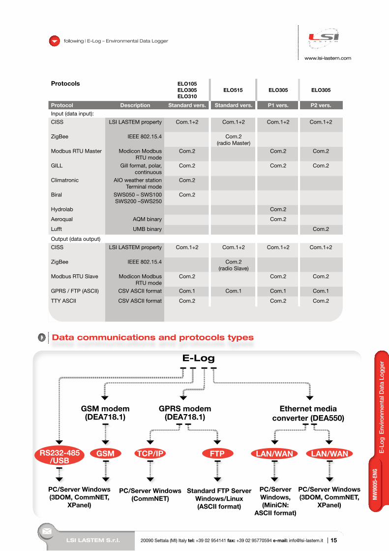
Protocols ELO105ELO305ELO310
ELO515 ELO305 ELO305
Protocol Description Standard vers. Standard vers. P1 vers. P2 vers.
Input (data input):
CISS LSI LASTEM property Com.1+2 Com.1+2 Com.1+2 Com.1+2
ZigBee IEEE 802.15.4 Com.2 (radio Master)
Modbus RTU Master Modicon Modbus RTU mode
Com.2 Com.2 Com.2
GILL Gill format, polar, continuous
Com.2 Com.2 Com.2
Climatronic AIO weather station Terminal mode
Com.2
Biral SWS050 – SWS100 SWS200 –SWS250
Com.2
Hydrolab Com.2
Aeroqual AQM binary Com.2
Lufft UMB binary Com.2
Output (data output)
CISS LSI LASTEM property Com.1+2 Com.1+2 Com.1+2 Com.1+2
ZigBee IEEE 802.15.4 Com.2 (radio Slave)
Modbus RTU Slave Modicon Modbus RTU mode
Com.2 Com.2 Com.2
GPRS / FTP (ASCII) CSV ASCII format Com.1 Com.1 Com.1 Com.1
TTY ASCII CSV ASCII format Com.2 Com.2 Com.2
Data communications and protocols types
15
MW
9005
-ENG
www.lsi-lastem.com
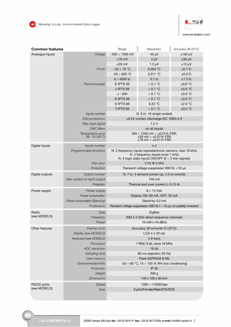
Common features Range Resolution Accuracy (@ 25°C)
Analogue inputs Voltage -300 ÷ 1200 mV 40 µV ±160 µV
±78 mV 3 µV ±30 µV
±39 mV 1.5 µV ±15 µV
Pt100 -50 ÷ 70 °C 0.003 °C ±0.1°C
-50 ÷ 600 °C 0.011 °C ±0.3°C
0 ÷ 6000 Ω 0.1 Ω ±1.5 Ω
Thermocouples E-IPTS 68 < 0.1 °C ±0.6 °C
J-IPTS 68 < 0.1 °C ±0.6 °C
J - DIN < 0.1 °C ±0.6 °C
K-IPTS 68 < 0.1 °C ±0.5 °C
S-IPTS 68 0.22 °C ±2.0 °C
T-IPTS 68 < 0.1 °C ±0.5 °C
Inputs number N. 8 (n. 16 single-ended)
ESD protections ±8 kV contact discharge IEC 1000–4-2
Max input signal 1.2 V
EMC filters on all inputs
Temperature error (@ -10÷30°C)
300 ÷ 1200 mV < ±0.01% FSR;±39 mV < ±0.01% FSR±78 mV < ±0.01% FSR
Digital inputs Inputs number n.4
Programmable functions N. 2 frequency inputs (optoelectronic sensors, max 10 kHz)N. 2 frequency inputs (max 1 kHz)
N. 4 logic state inputs ON/OFF (0 ÷ 3 Vdc signals)
Max error 3 Hz @ 5 kHz
Protection Transient voltage suppressor 600 W, <10 µs
Digital outputs Output number N. 7 (n. 4 sensors power-up, n.3 on events)
Max current on each output 150 mA
Protection Thermal and over current (> 0.15 A)
Power supply Power supply 8 ÷ 14 Vdc
Power consumption Display ON: 60 mA, OFF: 20 mA
Power consumption (Stand-by) Stand-by: 0.2 mA
Protections Transient voltage suppressor: 600 W, t = 10 µs; on polarity inversion
Radio(see MODELS)
Type ZigBee
Frequency ISM 2.4 GHz direct sequence channels
Power 10 mW (+10 dBm)
Other features Internal clock Accuracy 30 s/month (T=25°C)
Display (see MODELS) LCD 4 x 20 car
Keyboard (see MODELS) n.8 keys
Processor 1 RISC 8 bit, clock 16 MHz
ADC resolution 16 bit
Sampling time 80 ms (rejection 50 Hz)
Data memory Flash EEPROM 8 Mb
Environmental limits -20 ÷ 60 °C, 15 ÷ 100 % RH (not condensing)
Protection IP 40
Weight 500 g
Dimensions 140 x 120 x 50 mm
RS232 ports(see MODELS)
Speed 1200 ÷ 115200 bps
Type 9 pins/Female/Male/DTE/DCE
following | E-Log – Environmental Data Logger
16LSI LASTEM S.r.l. 20090 Settala (MI) Italy tel: +39 02 954141 fax: +39 02 95770594 e-mail: [email protected] |
LSI LASTEM S.r.l. 20090 Settala (MI) Italy tel: +39 02 954141 fax: +39 02 95770594 e-mail: [email protected] |
www.lsi-lastem.com
R-Log – Radio data logger
Highlights
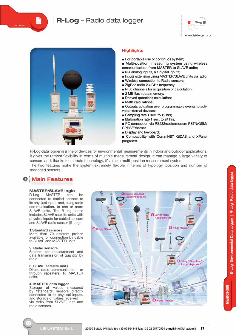
For portable use or continuos system; Multi-position measuring system using wireless communication from MASTER to SLAVE units; N.4 analog inputs, n.1 digital inputs; Inputs extension using MASTER/SLAVE units via radio; Wireless connection to Radio sensors; ZigBee radio 2.4 GHz frequency; N.50 channels for acquisition or calculation; 2 MB flash data memory; Derived quantities calculation; Math calculations; Outputs actuation over programmable events to acti-vate external devices; Sampling rate 1 sec. to 12 hrs; Elaboration rate 1 sec. to 24 hrs; PC connection via RS232/radio/modem PSTN/GSM/GPRS/Ethernet Display and keyboard; Compatibility with CommNET, GIDAS and XPanel programs.
R-Log data logger is a line of devices for environmental measurements in indoor and outdoor applications; it gives the utmost flexibility in terms of multiple measurement design. It can manage a large variety of sensors and, thanks to its radio technology, it’s also a multi-position measurement system. The two features make the system extremely flexible in terms of typology, position and number of managed sensors.
MASTER/SLAVE logicR-Log MASTER can be connected to cabled sensors to its physical inputs and, using radio communication, to one or more SLAVE units. The R-Log series includes SLAVE satellite units with physical inputs for cabled sensors and SLAVE radio sensor (S-Log).
1.Standard sensorsMore than 70 different probes available for connection by cable to SLAVE and MASTER units.
2. Radio sensorsSensors for measurement and data transmission of quantity by radio.
3. SLAVE satellite unitsDirect radio communication, or through repeaters, to MASTER units.
4. MASTER data loggerStorage of values measured by “standard” sensors directly connected to its physical inputs, and storage of values receivedvia radio from SLAVE units and radio sensors.
Main Features
> data loggers
E-L
og E
nviro
nmen
tal D
ata
Logg
er |
R-L
og R
adio
dat
a lo
gger
17
MW
9005
-ENG
LSI LASTEM S.r.l. 20090 Settala (MI) Italy tel: +39 02 954141 fax: +39 02 95770594 e-mail: [email protected] |
www.lsi-lastem.com
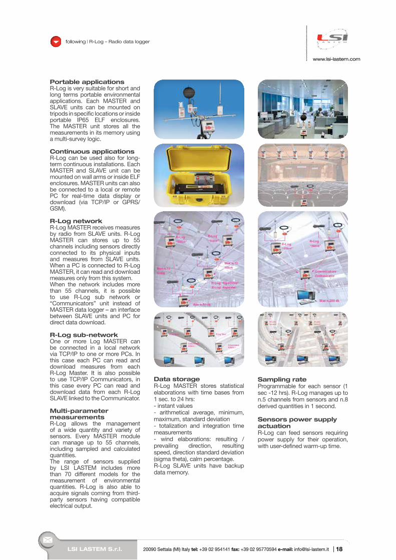
Portable applicationsR-Log is very suitable for short and long terms portable environmental applications. Each MASTER and SLAVE units can be mounted on tripods in specific locations or inside portable IP65 ELF enclosures. The MASTER unit stores all the measurements in its memory using a multi-survey logic.
Continuous applicationsR-Log can be used also for long-term continuous installations. Each MASTER and SLAVE unit can be mounted on wall arms or inside ELF enclosures. MASTER units can also be connected to a local or remote PC for real-time data display or download (via TCP/IP or GPRS/GSM).
R-Log networkR-Log MASTER receives measures by radio from SLAVE units. R-Log MASTER can stores up to 55 channels including sensors directly connected to its physical inputs and measures from SLAVE units. When a PC is connected to R-Log MASTER, it can read and download measures only from this system.When the network includes more than 55 channels, it is possible to use R-Log sub network or “Communicators” unit instead of MASTER data logger – an interface between SLAVE units and PC for direct data download.
R-Log sub-networkOne or more Log MASTER can be connected in a local network via TCP/IP to one or more PCs. In this case each PC can read and download measures from each R-Log Master. It is also possible to use TCP/IP Communicators, in this case every PC can read and download data from each R-Log SLAVE linked to the Communicator.
Multi-parameter measurementsR-Log allows the management of a wide quantity and variety of sensors. Every MASTER module can manage up to 55 channels, including sampled and calculated quantities.The range of sensors supplied by LSI LASTEM includes more than 70 different models for the measurement of environmental quantities. R-Log is also able to acquire signals coming from third-party sensors having compatible electrical output.
Data storageR-Log MASTER stores statistical elaborations with time bases from 1 sec. to 24 hrs:- instant values- arithmetical average, minimum, maximum, standard deviation- totalization and integration time measurements- wind elaborations: resulting /prevailing direction, resulting speed, direction standard deviation (sigma theta), calm percentage.R-Log SLAVE units have backup data memory.
Sampling rateProgrammable for each sensor (1 sec -12 hrs). R-Log manages up to n.5 channels from sensors and n.8 derived quantities in 1 second.
Sensors power supply actuationR-Log can feed sensors requiring power supply for their operation, with user-defined warm-up time.
following | R-Log – Radio data logger
18
R-L
og R
adio
dat
a lo
gger
LSI LASTEM S.r.l. 20090 Settala (MI) Italy tel: +39 02 954141 fax: +39 02 95770594 e-mail: [email protected] |
www.lsi-lastem.com
InputsMASTER and SLAVE units have the same number and type of inputs:- N. 4 inputs (n.8 single-ended) for analogue signals (voltage, current and resistance);- N. 1 digital input. It can be configured as input for frequency signals or as on/off input.
Direct connection to PCMASTER units can be directly connected to a PC with the following interfaces:- USB, using included adapter.- RS485 line drivers: distances up to 1 km, using DEA504 converter- Ethernet, using DEA550 converter - Bluetooth, using DEA300 adapter
Remote connection to PCMASTER units can be remotely connected to a PC with the following interfaces:- Telephone System: GSM modem- GPRS net: GSM/GPRS modem.- Long distances UHF radio communications
CommNetEG program can help managing both direct and remote connections with automatic/scheduled communications.
Derived environmental and mathematical calculationsR-Log has an internal library of derived environmental quantities. For their calculation R-Log can use inputs from monitoring measures,
user-defined constants and other derived quantities This library also includes mathematical calculations (see Calculated Quantities).
Models with mini-Din inputs and sensors self-recognition feature and models with terminal input board are available
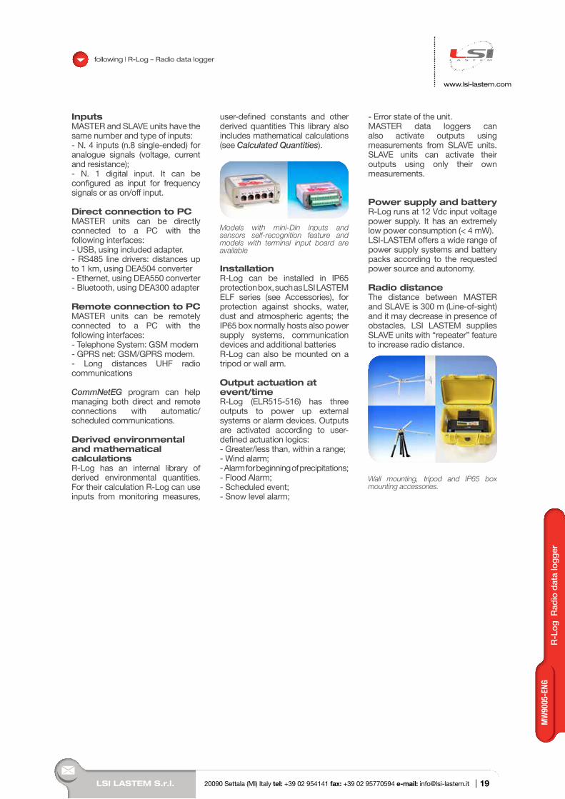
InstallationR-Log can be installed in IP65 protection box, such as LSI LASTEM ELF series (see Accessories), for protection against shocks, water, dust and atmospheric agents; the IP65 box normally hosts also power supply systems, communication devices and additional batteriesR-Log can also be mounted on a tripod or wall arm.
Output actuation at event/timeR-Log (ELR515-516) has three outputs to power up external systems or alarm devices. Outputs are activated according to user-defined actuation logics:- Greater/less than, within a range;- Wind alarm;- Alarm for beginning of precipitations;- Flood Alarm;- Scheduled event;- Snow level alarm;
- Error state of the unit.MASTER data loggers can also activate outputs using measurements from SLAVE units. SLAVE units can activate their outputs using only their own measurements.
Power supply and batteryR-Log runs at 12 Vdc input voltage power supply. It has an extremely low power consumption (< 4 mW).LSI-LASTEM offers a wide range of power supply systems and battery packs according to the requested power source and autonomy.
Radio distanceThe distance between MASTER and SLAVE is 300 m (Line-of-sight) and it may decrease in presence of obstacles. LSI LASTEM supplies SLAVE units with “repeater” feature to increase radio distance.
Wall mounting, tripod and IP65 box mounting accessories.
following | R-Log – Radio data logger
19
MW
9005
-ENG
LSI LASTEM S.r.l. 20090 Settala (MI) Italy tel: +39 02 954141 fax: +39 02 95770594 e-mail: [email protected] |
www.lsi-lastem.com
following | R-Log – Radio data logger
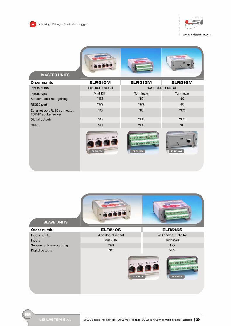
MASTER UNITS
Order numb. ELR510M ELR515M ELR516MInputs numb. 4 analog, 1 digital 4/8 analog, 1 digital
Inputs type Mini-DIN Terminals Terminals
Sensors auto-recognizing YES NO NO
RS232 port YES YES NO
Ethernet port RJ45 connector, TCP/IP socket server
NO NO YES
Digital outputs NO YES YES
GPRS NO YES NO
ELR510S ELR515S ELR516M
SLAVE UNITS
Order numb. ELR510S ELR515SInputs numb. 4 analog, 1 digital 4/8 analog, 1 digital
Inputs Mini-DIN Terminals
Sensors auto-recognizing YES NO
Digital outputs NO YES
ELR510S ELR515S
20
R-L
og R
adio
dat
a lo
gger
LSI LASTEM S.r.l. 20090 Settala (MI) Italy tel: +39 02 954141 fax: +39 02 95770594 e-mail: [email protected] |
following | R-Log – Radio data logger
www.lsi-lastem.com
continued
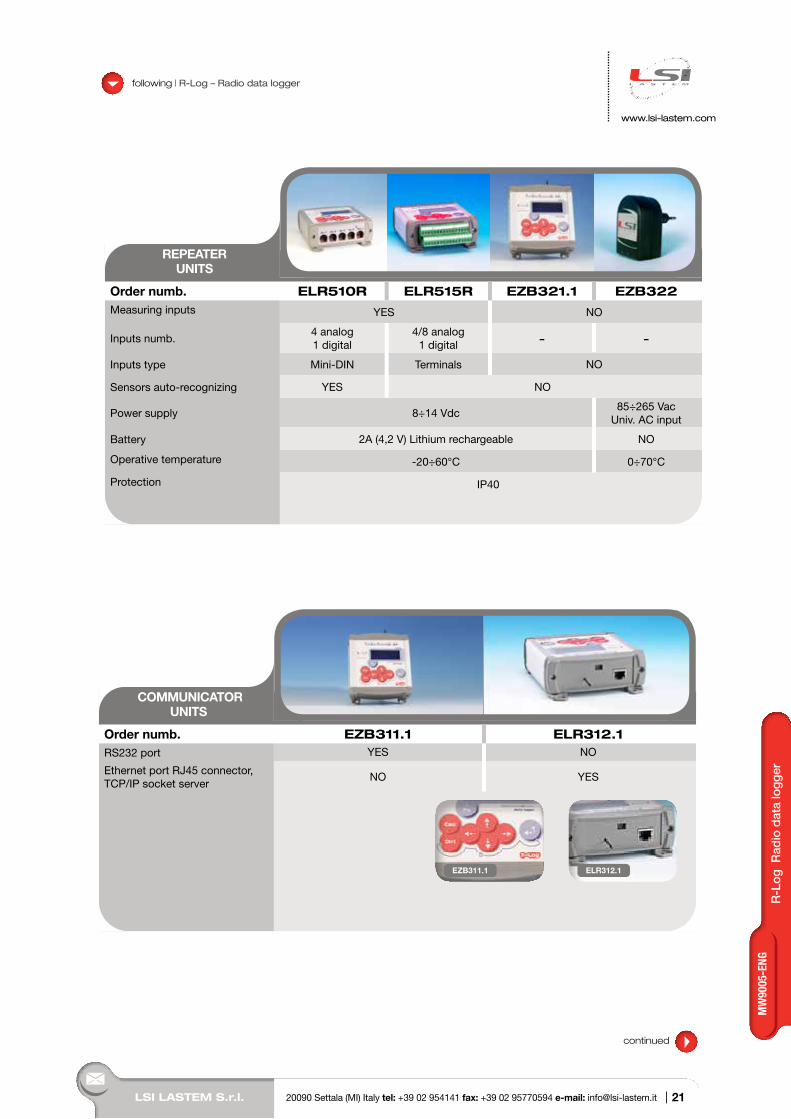
REPEATER UNITS
Order numb. ELR510R ELR515R EZB321.1 EZB322Measuring inputs YES NO
Inputs numb.4 analog1 digital
4/8 analog1 digital - -
Inputs type Mini-DIN Terminals NO
Sensors auto-recognizing YES NO
Power supply 8÷14 Vdc85÷265 Vac
Univ. AC input
Battery 2A (4,2 V) Lithium rechargeable NO
Operative temperature -20÷60°C 0÷70°C
Protection IP40
COMMUNICATORUNITS
Order numb. EZB311.1 ELR312.1RS232 port YES NO
Ethernet port RJ45 connector,TCP/IP socket server
NO YES
EZB311.1 ELR312.1
21
MW
9005
-ENG
LSI LASTEM S.r.l. 20090 Settala (MI) Italy tel: +39 02 954141 fax: +39 02 95770594 e-mail: [email protected] |
www.lsi-lastem.com
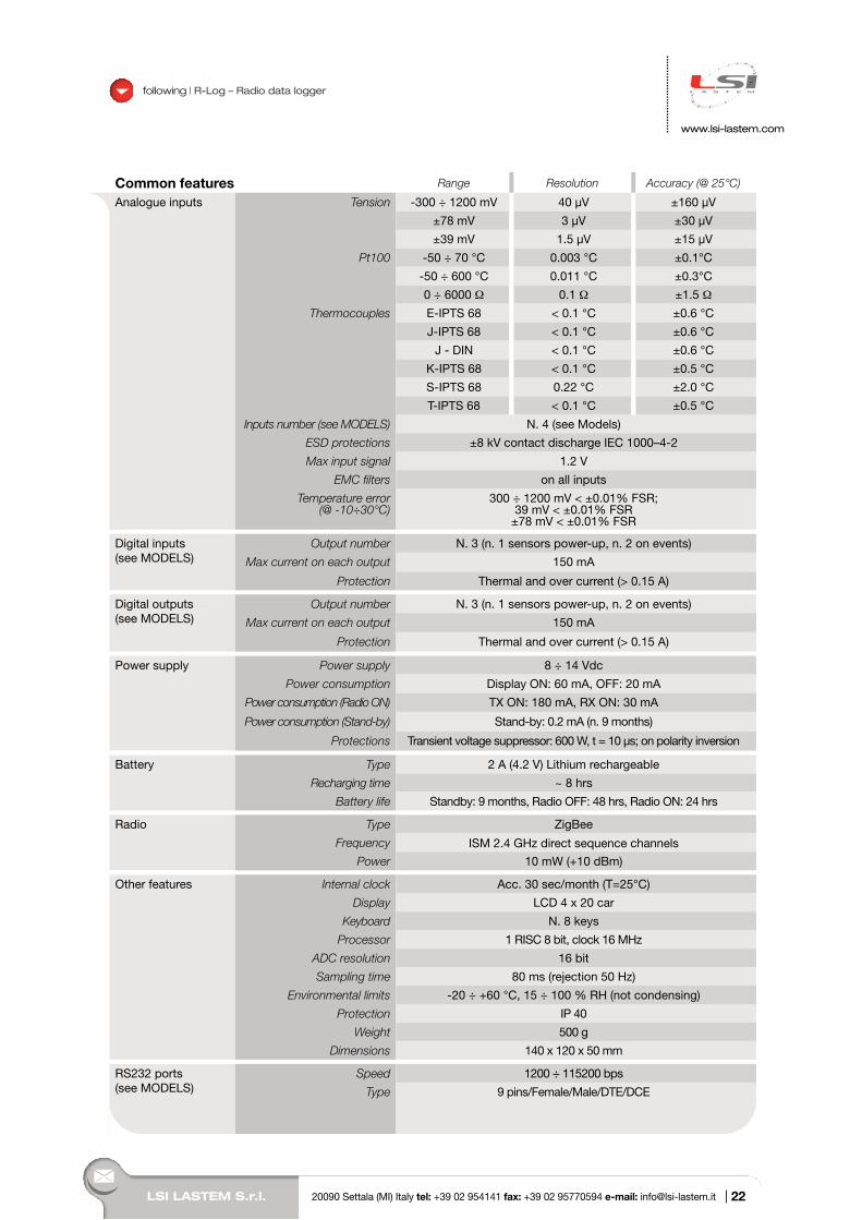
Common features Range Resolution Accuracy (@ 25°C)
Analogue inputs Tension -300 ÷ 1200 mV 40 µV ±160 µV
±78 mV 3 µV ±30 µV
±39 mV 1.5 µV ±15 µV
Pt100 -50 ÷ 70 °C 0.003 °C ±0.1°C
-50 ÷ 600 °C 0.011 °C ±0.3°C
0 ÷ 6000 Ω 0.1 Ω ±1.5 Ω
Thermocouples E-IPTS 68 < 0.1 °C ±0.6 °C
J-IPTS 68 < 0.1 °C ±0.6 °C
J - DIN < 0.1 °C ±0.6 °C
K-IPTS 68 < 0.1 °C ±0.5 °C
S-IPTS 68 0.22 °C ±2.0 °C
T-IPTS 68 < 0.1 °C ±0.5 °C
Inputs number (see MODELS) N. 4 (see Models)
ESD protections ±8 kV contact discharge IEC 1000–4-2
Max input signal 1.2 V
EMC filters on all inputs
Temperature error (@ -10÷30°C)
300 ÷ 1200 mV < ±0.01% FSR;39 mV < ±0.01% FSR
±78 mV < ±0.01% FSR
Digital inputs (see MODELS)
Output number N. 3 (n. 1 sensors power-up, n. 2 on events)
Max current on each output 150 mA
Protection Thermal and over current (> 0.15 A)
Digital outputs(see MODELS)
Output number N. 3 (n. 1 sensors power-up, n. 2 on events)
Max current on each output 150 mA
Protection Thermal and over current (> 0.15 A)
Power supply Power supply 8 ÷ 14 Vdc
Power consumption Display ON: 60 mA, OFF: 20 mA
Power consumption (Radio ON) TX ON: 180 mA, RX ON: 30 mA
Power consumption (Stand-by) Stand-by: 0.2 mA (n. 9 months)
Protections Transient voltage suppressor: 600 W, t = 10 µs; on polarity inversion
Battery Type 2 A (4.2 V) Lithium rechargeable
Recharging time ~ 8 hrs
Battery life Standby: 9 months, Radio OFF: 48 hrs, Radio ON: 24 hrs
Radio Type ZigBee
Frequency ISM 2.4 GHz direct sequence channels
Power 10 mW (+10 dBm)
Other features Internal clock Acc. 30 sec/month (T=25°C)
Display LCD 4 x 20 car
Keyboard N. 8 keys
Processor 1 RISC 8 bit, clock 16 MHz
ADC resolution 16 bit
Sampling time 80 ms (rejection 50 Hz)
Environmental limits -20 ÷ +60 °C, 15 ÷ 100 % RH (not condensing)
Protection IP 40
Weight 500 g
Dimensions 140 x 120 x 50 mm
RS232 ports(see MODELS)
Speed 1200 ÷ 115200 bps
Type 9 pins/Female/Male/DTE/DCE
following | R-Log – Radio data logger
22
LSI LASTEM S.r.l. 20090 Settala (MI) Italy tel: +39 02 954141 fax: +39 02 95770594 e-mail: [email protected] |
www.lsi-lastem.com
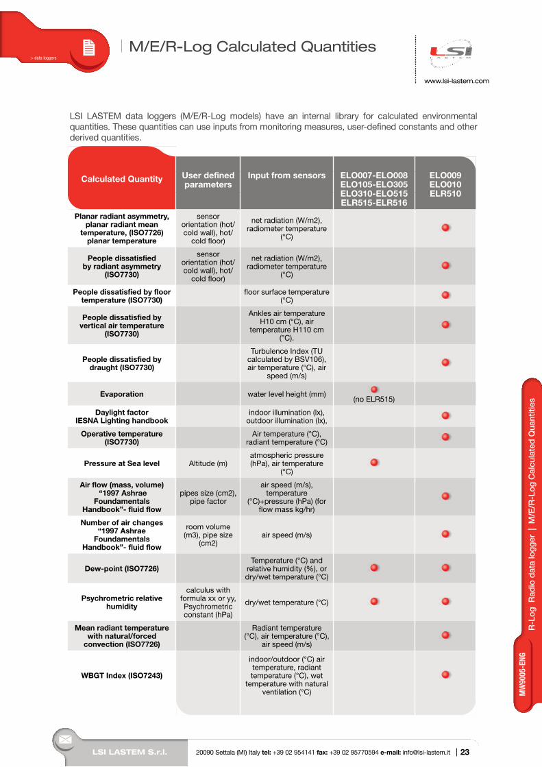
LSI LASTEM data loggers (M/E/R-Log models) have an internal library for calculated environmental quantities. These quantities can use inputs from monitoring measures, user-defined constants and other derived quantities.
M/E/R-Log Calculated Quantities
Calculated Quantity User defined parameters
Input from sensors ELO007-ELO008 ELO105-ELO305 ELO310-ELO515 ELR515-ELR516
ELO009 ELO010 ELR510
Planar radiant asymmetry, planar radiant mean
temperature, (ISO7726) planar temperature
sensor orientation (hot/cold wall), hot/
cold floor)
net radiation (W/m2), radiometer temperature
(°C)
People dissatisfied by radiant asymmetry
(ISO7730)
sensor orientation (hot/cold wall), hot/
cold floor)
net radiation (W/m2), radiometer temperature
(°C)
People dissatisfied by floor temperature (ISO7730)
floor surface temperature (°C)
People dissatisfied by vertical air temperature
(ISO7730)
Ankles air temperature H10 cm (°C), air
temperature H110 cm (°C).
People dissatisfied by draught (ISO7730)
Turbulence Index (TU calculated by BSV106), air temperature (°C), air
speed (m/s)
Evaporation water level height (mm)(no ELR515)
Daylight factorIESNA Lighting handbook
indoor illumination (lx), outdoor illumination (lx),
Operative temperature (ISO7730)
Air temperature (°C), radiant temperature (°C)
Pressure at Sea level Altitude (m)atmospheric pressure (hPa), air temperature
(°C)
Air flow (mass, volume) “1997 Ashrae
Foundamentals Handbook”- fluid flow
pipes size (cm2), pipe factor
air speed (m/s), temperature
(°C)+pressure (hPa) (for flow mass kg/hr)
Number of air changes“1997 Ashrae
Foundamentals Handbook”- fluid flow
room volume (m3), pipe size
(cm2)air speed (m/s)
Dew-point (ISO7726)Temperature (°C) and
relative humidity (%), or dry/wet temperature (°C)
Psychrometric relative humidity
calculus with formula xx or yy, Psychrometric constant (hPa)
dry/wet temperature (°C)
Mean radiant temperature with natural/forced
convection (ISO7726)
Radiant temperature (°C), air temperature (°C),
air speed (m/s)
WBGT Index (ISO7243)
indoor/outdoor (°C) air temperature, radiant temperature (°C), wet
temperature with natural ventilation (°C)
> data loggers
R-L
og R
adio
dat
a lo
gger
| M
/E/R
-Log
Cal
cula
ted
Qua
ntiti
es
23
MW
9005
-ENG
LSI LASTEM S.r.l. 20090 Settala (MI) Italy tel: +39 02 954141 fax: +39 02 95770594 e-mail: [email protected] |
www.lsi-lastem.com
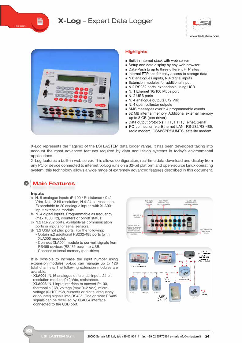
X-Log – Expert Data Logger
Highlights
Built-in internet stack with web server Setup and data display by any web browser Data-Push to up to three different FTP sites Internal FTP site for easy access to storage data N.8 analogues inputs, N.4 digital inputs Extension modules for additional input N.2 RS232 ports, expandable using USB N. 1 Ehernet 10/100 Mbps port N. 2 USB ports N. 4 analogue outputs 0÷2 Vdc N. 4 open collector outputs SMS messages over n.4 programmable events 32 MB internal memory. Additional external memory up to 8 GB (pen-driver) Data output protocols: FTP, HTTP, Telnet, Serial PC connection via Ethernet LAN, RS-232/RS-485, radio modem, GSM/GPRS/UMTS, satellite modem.
X-Log represents the flagship of the LSI LASTEM data logger range. It has been developed taking into account the most advanced features required by data acquisition systems in today’s environmental applications. X-Log features a built-in web server. This allows configuration, real-time data download and display from any PC or device connected to internet. X-Log runs on a 32-bit platform and open-source Linux operating system; this technology allows a wide range of extremely advanced features described in this document.
Main Features
> data loggers
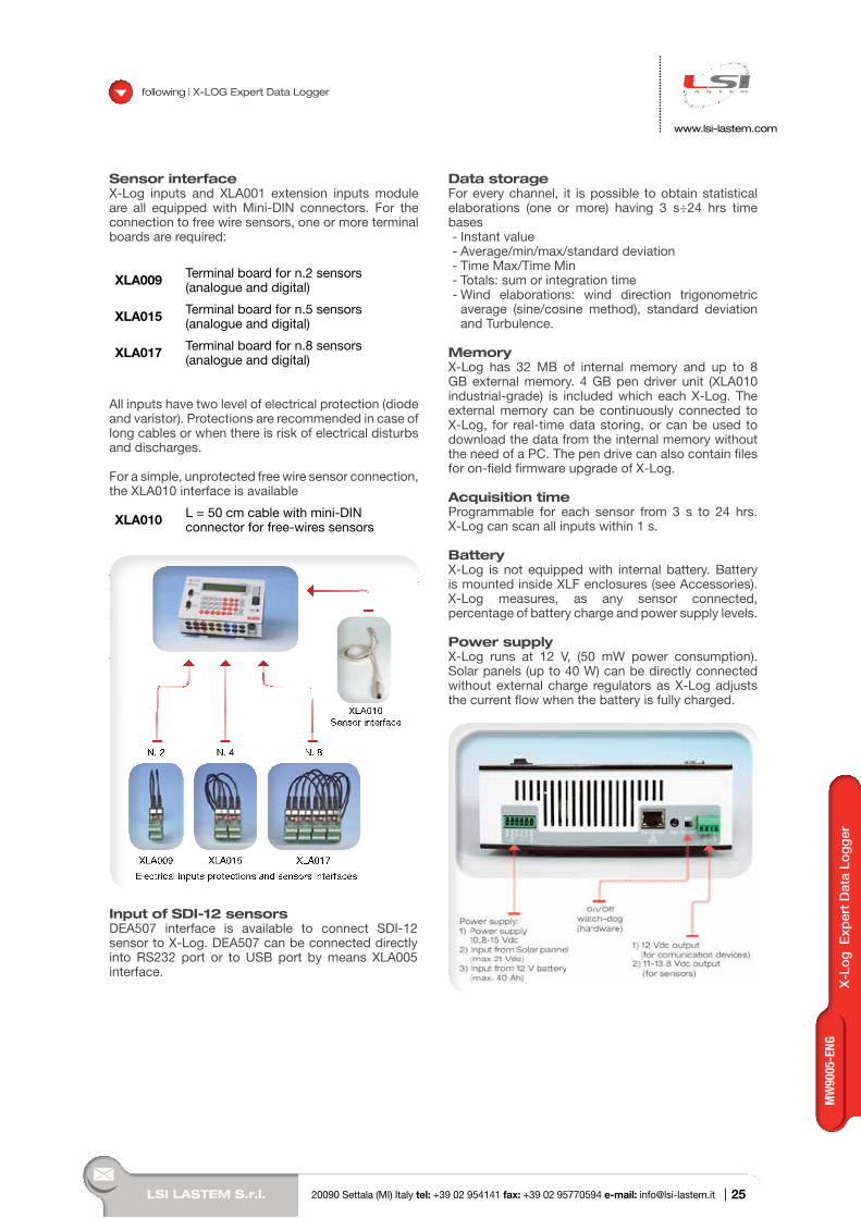
Inputsa- N. 8 analogue inputs (Pt100 / Resistance / 0÷2
Vdc). N.4-12 bit resolution, N.4-24 bit resolution. Expandable to 20 analogue inputs with XLA001 input extension module.
b- N. 4 digital inputs. Programmable as frequency (max.1000 Hz), counters or on/off status
c- N.2 RS-232 ports. Available as communication ports or inputs for serial sensors.
d- N.2 USB hot plug ports. For the following: - Obtain n.2 additional RS232/485 ports (with
XLA005 module). - Connect XLA004 module to convert signals from
RS485 devices (RS485 bus) into USB. - Connect external memory (pen-drive).
It is possible to increase the input number using expansion modules. X-Log can manage up to 128 total channels. The following extension modules are available:- XLA001: N.16 analogue differential inputs 24 bit
resolution module (0÷2 Vdc, resistance).- XLA003: N.1 input interface to convert Pt100,
thermopile (µV), voltage (max 0÷2 Vdc), micro-voltage (0÷100 mV), currents or digital (frequency or counter) signals into RS485. One or more RS485 signals can be received by XLA004 interface connected to the USB port.
24
LSI LASTEM S.r.l. 20090 Settala (MI) Italy tel: +39 02 954141 fax: +39 02 95770594 e-mail: [email protected] |
X-L
og E
xper
t D
ata
Logg
er
www.lsi-lastem.com
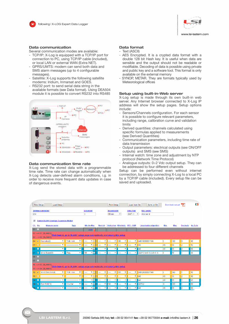
Sensor interfaceX-Log inputs and XLA001 extension inputs module are all equipped with Mini-DIN connectors. For the connection to free wire sensors, one or more terminal boards are required:
XLA009 Terminal board for n.2 sensors (analogue and digital)
XLA015 Terminal board for n.5 sensors(analogue and digital)
XLA017 Terminal board for n.8 sensors(analogue and digital)
All inputs have two level of electrical protection (diode and varistor). Protections are recommended in case of long cables or when there is risk of electrical disturbs and discharges.
For a simple, unprotected free wire sensor connection, the XLA010 interface is available
XLA010 L = 50 cm cable with mini-DIN connector for free-wires sensors
All inputs have two level of electrical protection (diode and varistor). Protections are recommended in case of long cables or when there is risk of electrical disturbs and discharges.
For a simple, unprotected free wire sensor connection, the XLA010 interface is available
XLA010 L. 50 cm cable with mini-DIN connector for free-wires sensors
Input of SDI-12 sensorsDEA507 interface is available to connect SDI-12 sensor to X-Log. DEA507 can be connected directly into RS232 port or to USB port by means XLA005 interface.
Data storageFor every channel, it is possible to obtain statistical elaborations (one or more) having 3 s÷24 hrs time bases - Instant value- Average/min/max/standard deviation- Time Max/Time Min- Totals: sum or integration time- Wind elaborations: wind direction trigonometric
average (sine/cosine method), standard deviation and Turbulence.
MemoryX-Log has 32 MB of internal memory and up to 8 GB external memory. 4 GB pen driver unit (XLA010 industrial-grade) is included which each X-Log. The external memory can be continuously connected to X-Log, for real-time data storing, or can be used to download the data from the internal memory without the need of a PC. The pen drive can also contain files for on-field firmware upgrade of X-Log.
Acquisition timeProgrammable for each sensor from 3 s to 24 hrs. X-Log can scan all inputs within 1 s.
BatteryX-Log is not equipped with internal battery. Battery is mounted inside XLF enclosures (see Accessories). X-Log measures, as any sensor connected, percentage of battery charge and power supply levels.
Power supplyX-Log runs at 12 V, (50 mW power consumption). Solar panels (up to 40 W) can be directly connected without external charge regulators as X-Log adjusts the current flow when the battery is fully charged.
following | X-LOG Expert Data Logger
25
MW
9005
-ENG
LSI LASTEM S.r.l. 20090 Settala (MI) Italy tel: +39 02 954141 fax: +39 02 95770594 e-mail: [email protected] |
www.lsi-lastem.com
following | X-LOG Expert Data Logger
Data communicationSeveral communication modes are available:- TCP/IP: X-Log is equipped with a TCP/IP port for
connection to PC, using TCP/IP cable (included), or local LAN or external WAN (Extra NET).
- GPRS/UMTS: modem can send both data and SMS alarm messages (up to 4 configurable messages).
- Satellite: X-Log supports the following satellite modems: Iridium, Inmarsat and GOES.
- RS232 port: to send serial data string in the available formats (see Data format). Using DEA504 module it is possible to convert RS232 into RS485
Data communication time rateX-Log send the stored data with a programmable time rate. Time rate can change automatically when X-Log detects user-defined alarm conditions, i.g. in order to receive more frequent data updates in case of dangerous events.
Data format- Text (ASCII)- AES Encrypted. It is a crypted data format with a
double 128 bit Hash key. It is useful when data are sensible and the output should not be readable or modifiable. Decoding of data is possible using private and public key and a software tool. This format is only available on the external memory
- SYNOP, METAR. They are formats typically used by Meteorological offices
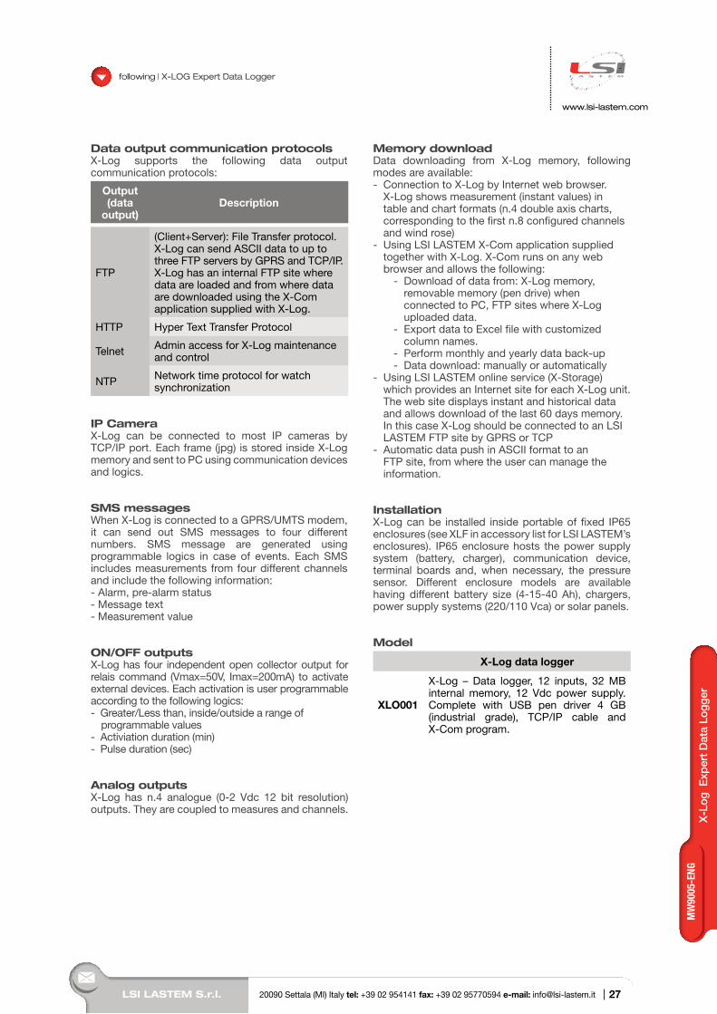
Setup using built-in-Web serverX-Log setup is made through its own built-in web server. Any Internet browser connected to X-Log IP address will show the setup pages. Setup options include:- Sensors/Channels configuration. For each sensor
it is possible to configure relevant parameters, including range, calibration curve and validation limits
- Derived quantities: channels calculated using specific formulas applied to measurements (see Derived Quantities)
- Communication parameters, including time rate of data transmission
- Output parameters: electrical outputs (see ON/OFF outputs) and SMS (see SMS)
- Internal watch: time zone and adjustment by NTP protocol (Network Time Protocol)
- Analogue outputs: 0÷2 Vdc output setup. They can be addressed to four different channels
Setup can be performed even without internet connection, by simply connecting X-Log to a local PC by a TCP/IP cable (included). Every setup file can be saved and uploaded.
26
LSI LASTEM S.r.l. 20090 Settala (MI) Italy tel: +39 02 954141 fax: +39 02 95770594 e-mail: [email protected] |
X-L
og E
xper
t D
ata
Logg
er
www.lsi-lastem.com
following | X-LOG Expert Data Logger
Data output communication protocolsX-Log supports the following data output communication protocols:
Output (data
output)Description
FTP
(Client+Server): File Transfer protocol. X-Log can send ASCII data to up to three FTP servers by GPRS and TCP/IP. X-Log has an internal FTP site where data are loaded and from where data are downloaded using the X-Com application supplied with X-Log.
HTTP Hyper Text Transfer Protocol
Telnet Admin access for X-Log maintenance and control
NTP Network time protocol for watch synchronization
IP CameraX-Log can be connected to most IP cameras by TCP/IP port. Each frame (jpg) is stored inside X-Log memory and sent to PC using communication devices and logics.
SMS messagesWhen X-Log is connected to a GPRS/UMTS modem, it can send out SMS messages to four different numbers. SMS message are generated using programmable logics in case of events. Each SMS includes measurements from four different channels and include the following information:- Alarm, pre-alarm status- Message text- Measurement value
ON/OFF outputsX-Log has four independent open collector output for relais command (Vmax=50V, Imax=200mA) to activate external devices. Each activation is user programmable according to the following logics:- Greater/Less than, inside/outside a range of
programmable values- Activiation duration (min)- Pulse duration (sec)
Analog outputsX-Log has n.4 analogue (0-2 Vdc 12 bit resolution) outputs. They are coupled to measures and channels.
Memory downloadData downloading from X-Log memory, following modes are available:- Connection to X-Log by Internet web browser.
X-Log shows measurement (instant values) in table and chart formats (n.4 double axis charts, corresponding to the first n.8 configured channels and wind rose)
- Using LSI LASTEM X-Com application supplied together with X-Log. X-Com runs on any web browser and allows the following:
- Download of data from: X-Log memory, removable memory (pen drive) when connected to PC, FTP sites where X-Log uploaded data.
- Export data to Excel file with customized column names.
- Perform monthly and yearly data back-up- Data download: manually or automatically
- Using LSI LASTEM online service (X-Storage) which provides an Internet site for each X-Log unit. The web site displays instant and historical data and allows download of the last 60 days memory. In this case X-Log should be connected to an LSI LASTEM FTP site by GPRS or TCP
- Automatic data push in ASCII format to an FTP site, from where the user can manage the information.
InstallationX-Log can be installed inside portable of fixed IP65 enclosures (see XLF in accessory list for LSI LASTEM’s enclosures). IP65 enclosure hosts the power supply system (battery, charger), communication device, terminal boards and, when necessary, the pressure sensor. Different enclosure models are available having different battery size (4-15-40 Ah), chargers, power supply systems (220/110 Vca) or solar panels.
Model
X-Log data logger
XLO001
X-Log – Data logger, 12 inputs, 32 MB internal memory, 12 Vdc power supply. Complete with USB pen driver 4 GB (industrial grade), TCP/IP cable and X-Com program.
27
MW
9005
-ENG
LSI LASTEM S.r.l. 20090 Settala (MI) Italy tel: +39 02 954141 fax: +39 02 95770594 e-mail: [email protected] |
www.lsi-lastem.com
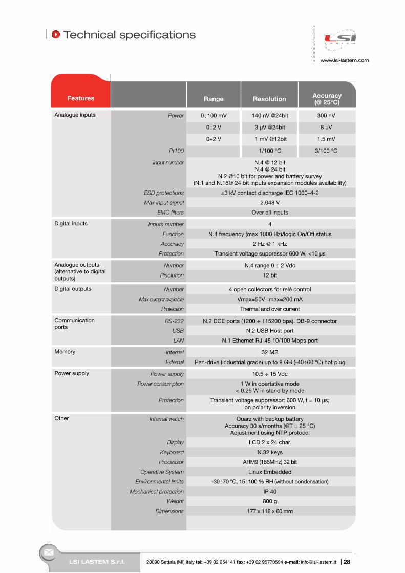
Analogue inputs Power 0÷100 mV 140 nV @24bit 300 nV
0÷2 V 3 µV @24bit 8 µV
0÷2 V 1 mV @12bit 1.5 mV
Pt100 1/100 °C 3/100 °C
Input number N.4 @ 12 bitN.4 @ 24 bit
N.2 @10 bit for power and battery survey(N.1 and N.16@ 24 bit inputs expansion modules availability)
ESD protections ±3 kV contact discharge IEC 1000–4-2
Max input signal 2.048 V
EMC filters Over all inputs
Digital inputs Inputs number 4
Function N.4 frequency (max 1000 Hz)/logic On/Off status
Accuracy 2 Hz @ 1 kHz
Protection Transient voltage suppressor 600 W, <10 µs
Analogue outputs (alternative to digital outputs)
Number N.4 range 0 ÷ 2 Vdc
Risolution 12 bit
Digital outputs Number 4 open collectors for relé control
Max current available Vmax=50V, Imax=200 mA
Protection Thermal and over current
Communication ports
RS-232 N.2 DCE ports (1200 ÷ 115200 bps), DB-9 connector
USB N.2 USB Host port
LAN N.1 Ethernet RJ-45 10/100 Mbps port
Memory Internal 32 MB
External Pen-drive (industrial grade) up to 8 GB (-40÷60 °C) hot plug
Power supply Power supply 10.5 ÷ 15 Vdc
Power consumption 1 W in opertative mode< 0.25 W in stand by mode
Protection Transient voltage suppressor: 600 W, t = 10 µs; on polarity inversion
Other Internal watch Quarz with backup batteryAccuracy 30 s/months (@T = 25 °C)
Adjustment using NTP protocol
Display LCD 2 x 24 char.
Keyboard N.32 keys
Processor ARM9 (166MHz) 32 bit
Operative System Linux Embedded
Environmental limits -30÷70 °C, 15÷100 % RH (without condensation)
Mechanical protection IP 40
Weight 800 g
Dimensions 177 x 118 x 60 mm
Features Range Resolution Accuracy (@ 25°C)
Technical specifications
28
LSI LASTEM S.r.l. 20090 Settala (MI) Italy tel: +39 02 954141 fax: +39 02 95770594 e-mail: [email protected] |
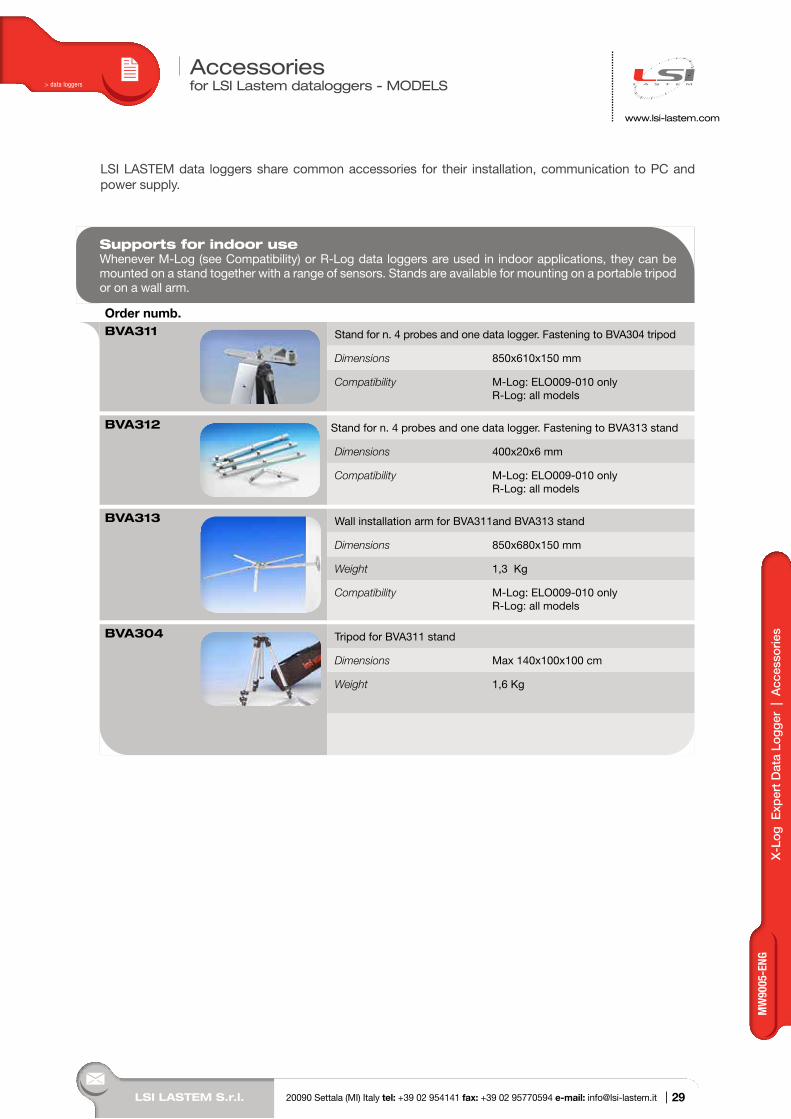
Accessories for LSI Lastem dataloggers - MODELS> data loggers
LSI LASTEM data loggers share common accessories for their installation, communication to PC and power supply.
Supports for indoor useWhenever M-Log (see Compatibility) or R-Log data loggers are used in indoor applications, they can be mounted on a stand together with a range of sensors. Stands are available for mounting on a portable tripod or on a wall arm.
Order numb.BVA311 Stand for n. 4 probes and one data logger. Fastening to BVA304 tripod
Dimensions 850x610x150 mm
Compatibility M-Log: ELO009-010 only R-Log: all models
BVA312 Stand for n. 4 probes and one data logger. Fastening to BVA313 stand
Dimensions 400x20x6 mm
Compatibility M-Log: ELO009-010 only R-Log: all models
BVA313 Wall installation arm for BVA311and BVA313 stand
Dimensions 850x680x150 mm
Weight 1,3 Kg
Compatibility M-Log: ELO009-010 only R-Log: all models
BVA304 Tripod for BVA311 stand
Dimensions Max 140x100x100 cm
Weight 1,6 Kg
www.lsi-lastem.com
X-L
og E
xper
t D
ata
Logg
er |
Acc
esso
ries
29
MW
9005
-ENG
LSI LASTEM S.r.l. 20090 Settala (MI) Italy tel: +39 02 954141 fax: +39 02 95770594 e-mail: [email protected] |
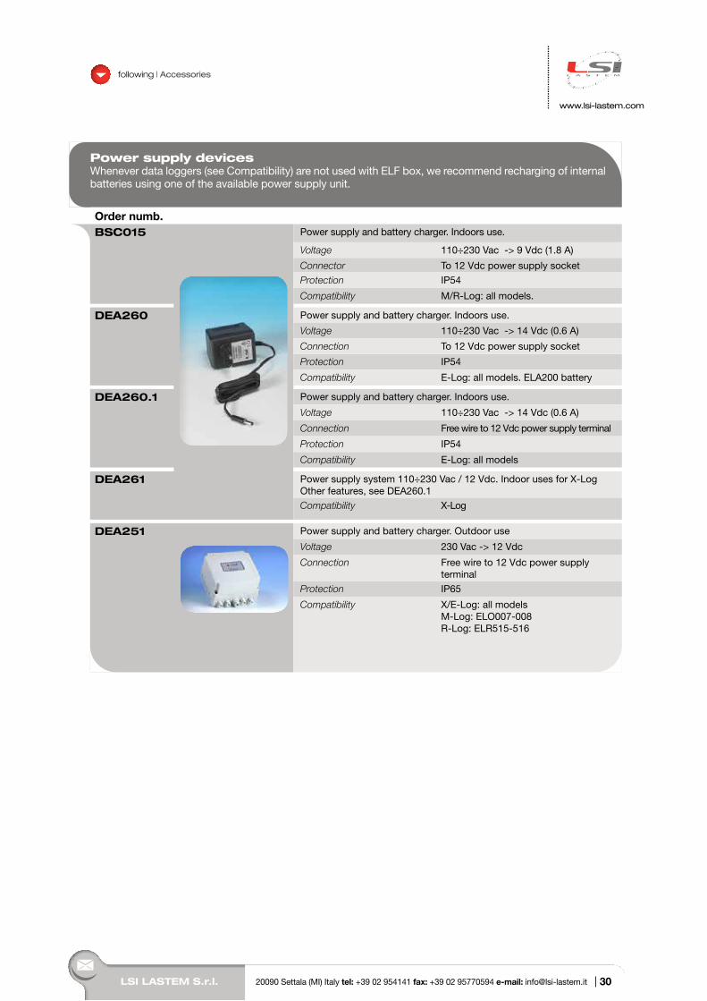
Power supply devicesWhenever data loggers (see Compatibility) are not used with ELF box, we recommend recharging of internal batteries using one of the available power supply unit.
Order numb.BSC015 Power supply and battery charger. Indoors use.
Voltage 110÷230 Vac -> 9 Vdc (1.8 A)
Connector To 12 Vdc power supply socket
Protection IP54
Compatibility M/R-Log: all models.
DEA260 Power supply and battery charger. Indoors use.
Voltage 110÷230 Vac -> 14 Vdc (0.6 A)
Connection To 12 Vdc power supply socket
Protection IP54
Compatibility E-Log: all models. ELA200 battery
DEA260.1 Power supply and battery charger. Indoors use.
Voltage 110÷230 Vac -> 14 Vdc (0.6 A)
Connection Free wire to 12 Vdc power supply terminal
Protection IP54
Compatibility E-Log: all models
DEA261 Power supply system 110÷230 Vac / 12 Vdc. Indoor uses for X-LogOther features, see DEA260.1
Compatibility X-Log
DEA251 Power supply and battery charger. Outdoor use
Voltage 230 Vac -> 12 Vdc
Connection Free wire to 12 Vdc power supply terminal
Protection IP65
Compatibility X/E-Log: all modelsM-Log: ELO007-008R-Log: ELR515-516
following | Accessories
www.lsi-lastem.com
30
LSI LASTEM S.r.l. 20090 Settala (MI) Italy tel: +39 02 954141 fax: +39 02 95770594 e-mail: [email protected] |
Acc
esso
ries
following | Accessories
www.lsi-lastem.com
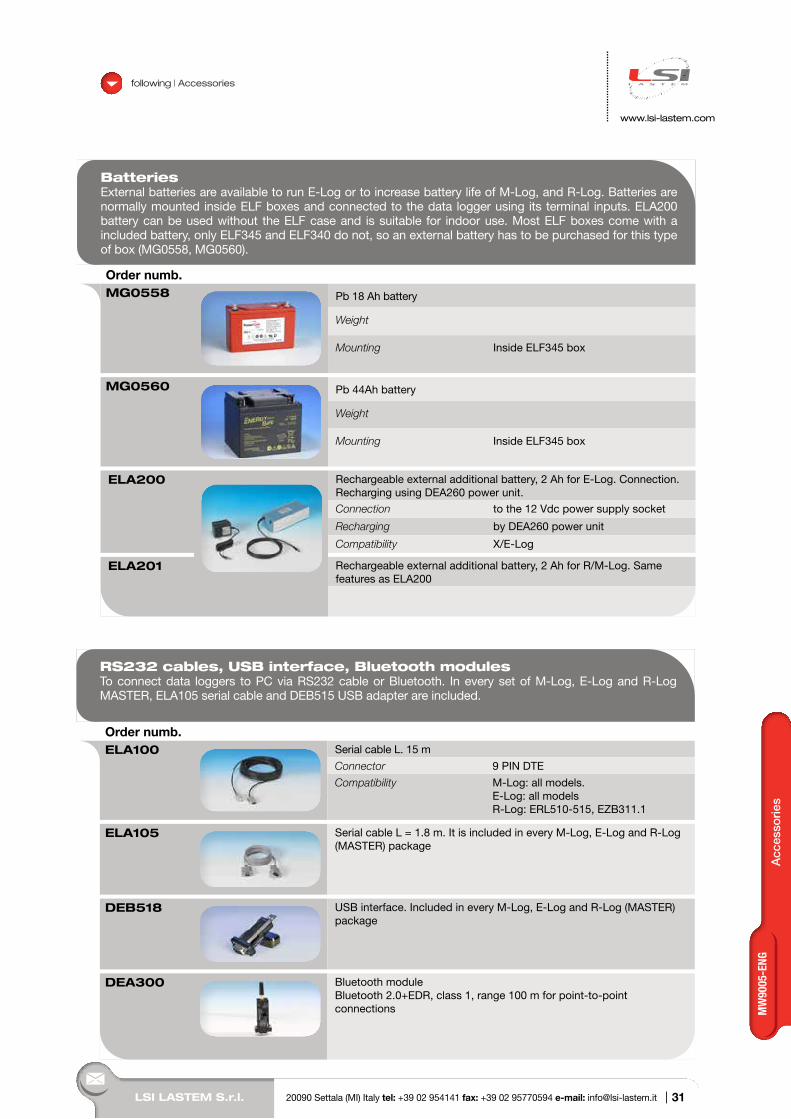
BatteriesExternal batteries are available to run E-Log or to increase battery life of M-Log, and R-Log. Batteries are normally mounted inside ELF boxes and connected to the data logger using its terminal inputs. ELA200 battery can be used without the ELF case and is suitable for indoor use. Most ELF boxes come with a included battery, only ELF345 and ELF340 do not, so an external battery has to be purchased for this type of box (MG0558, MG0560).
Order numb.MG0558 Pb 18 Ah battery
Weight
Mounting Inside ELF345 box
MG0560 Pb 44Ah battery
Weight
Mounting Inside ELF345 box
ELA200 Rechargeable external additional battery, 2 Ah for E-Log. Connection. Recharging using DEA260 power unit.
Connection to the 12 Vdc power supply socket
Recharging by DEA260 power unit
Compatibility X/E-Log
ELA201 Rechargeable external additional battery, 2 Ah for R/M-Log. Same features as ELA200
RS232 cables, USB interface, Bluetooth modulesTo connect data loggers to PC via RS232 cable or Bluetooth. In every set of M-Log, E-Log and R-Log MASTER, ELA105 serial cable and DEB515 USB adapter are included.
Order numb.ELA100 Serial cable L. 15 m
Connector 9 PIN DTE
Compatibility M-Log: all models. E-Log: all models R-Log: ERL510-515, EZB311.1
ELA105 Serial cable L = 1.8 m. It is included in every M-Log, E-Log and R-Log (MASTER) package
DEB518 USB interface. Included in every M-Log, E-Log and R-Log (MASTER) package
DEA300 Bluetooth moduleBluetooth 2.0+EDR, class 1, range 100 m for point-to-point connections
31
MW
9005
-ENG
LSI LASTEM S.r.l. 20090 Settala (MI) Italy tel: +39 02 954141 fax: +39 02 95770594 e-mail: [email protected] |
following | Accessories
www.lsi-lastem.com
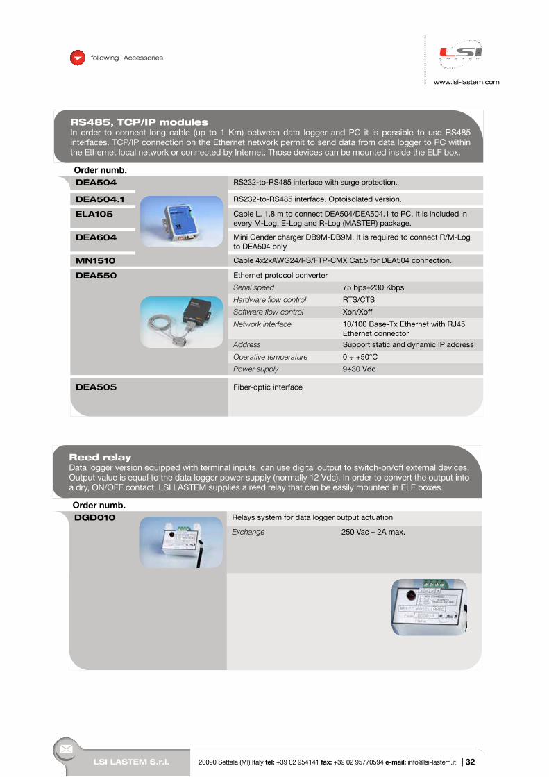
RS485, TCP/IP modulesIn order to connect long cable (up to 1 Km) between data logger and PC it is possible to use RS485 interfaces. TCP/IP connection on the Ethernet network permit to send data from data logger to PC within the Ethernet local network or connected by Internet. Those devices can be mounted inside the ELF box.
Order numb.DEA504 RS232-to-RS485 interface with surge protection.
DEA504.1 RS232-to-RS485 interface. Optoisolated version.
ELA105 Cable L. 1.8 m to connect DEA504/DEA504.1 to PC. It is included in every M-Log, E-Log and R-Log (MASTER) package.
DEA604 Mini Gender charger DB9M-DB9M. It is required to connect R/M-Log to DEA504 only
MN1510 Cable 4x2xAWG24/I-S/FTP-CMX Cat.5 for DEA504 connection.
DEA550 Ethernet protocol converter
Serial speed 75 bps÷230 Kbps
Hardware flow control RTS/CTS
Software flow control Xon/Xoff
Network interface 10/100 Base-Tx Ethernet with RJ45 Ethernet connector
Address Support static and dynamic IP address
Operative temperature 0 ÷ +50°C
Power supply 9÷30 Vdc
DEA505 Fiber-optic interface
Reed relayData logger version equipped with terminal inputs, can use digital output to switch-on/off external devices. Output value is equal to the data logger power supply (normally 12 Vdc). In order to convert the output into a dry, ON/OFF contact, LSI LASTEM supplies a reed relay that can be easily mounted in ELF boxes.
Order numb.DGD010 Relays system for data logger output actuation
Exchange 250 Vac – 2A max.
32
Acc
esso
ries
LSI LASTEM S.r.l. 20090 Settala (MI) Italy tel: +39 02 954141 fax: +39 02 95770594 e-mail: [email protected] |
following | Accessories
www.lsi-lastem.com
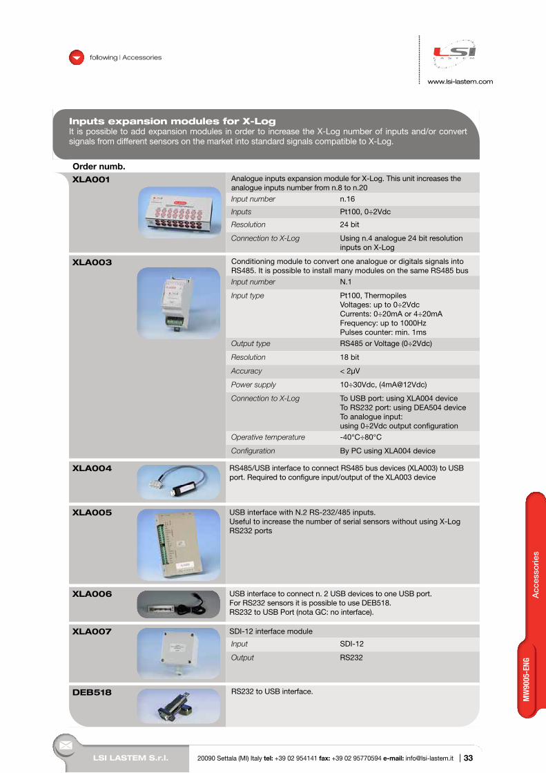
Inputs expansion modules for X-LogIt is possible to add expansion modules in order to increase the X-Log number of inputs and/or convert signals from different sensors on the market into standard signals compatible to X-Log.
Order numb.XLA001 Analogue inputs expansion module for X-Log. This unit increases the
analogue inputs number from n.8 to n.20
Input number n.16
Inputs Pt100, 0÷2Vdc
Resolution 24 bit
Connection to X-Log Using n.4 analogue 24 bit resolution inputs on X-Log
XLA003 Conditioning module to convert one analogue or digitals signals into RS485. It is possible to install many modules on the same RS485 bus
Input number N.1
Input type Pt100, ThermopilesVoltages: up to 0÷2VdcCurrents: 0÷20mA or 4÷20mAFrequency: up to 1000HzPulses counter: min. 1ms
Output type RS485 or Voltage (0÷2Vdc)
Resolution 18 bit
Accuracy < 2µV
Power supply 10÷30Vdc, (4mA@12Vdc)
Connection to X-Log To USB port: using XLA004 deviceTo RS232 port: using DEA504 deviceTo analogue input: using 0÷2Vdc output configuration
Operative temperature -40°C÷80°C
Configuration By PC using XLA004 device
XLA004 RS485/USB interface to connect RS485 bus devices (XLA003) to USB port. Required to configure input/output of the XLA003 device
XLA005 USB interface with N.2 RS-232/485 inputs. Useful to increase the number of serial sensors without using X-Log RS232 ports
XLA006 USB interface to connect n. 2 USB devices to one USB port. For RS232 sensors it is possible to use DEB518. RS232 to USB Port (nota GC: no interface).
XLA007 SDI-12 interface module
Input SDI-12
Output RS232
DEB518 RS232 to USB interface.
33
MW
9005
-ENG
LSI LASTEM S.r.l. 20090 Settala (MI) Italy tel: +39 02 954141 fax: +39 02 95770594 e-mail: [email protected] |
following | Accessories
www.lsi-lastem.com
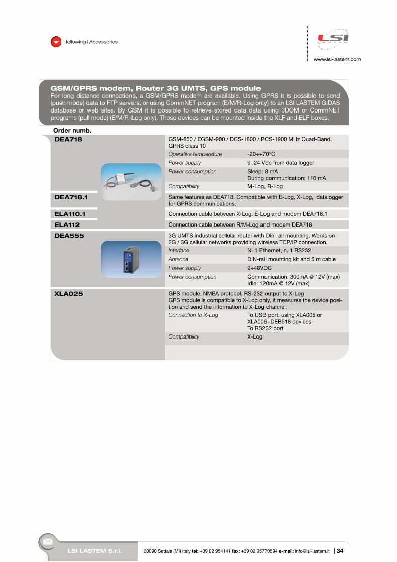
GSM/GPRS modem, Router 3G UMTS, GPS moduleFor long distance connections, a GSM/GPRS modem are available. Using GPRS it is possible to send (push mode) data to FTP servers, or using CommNET program (E/M/R-Log only) to an LSI LASTEM GIDAS database or web sites. By GSM it is possible to retrieve stored data data using 3DOM or CommNET programs (pull mode) (E/M/R-Log only). Those devices can be mounted inside the XLF and ELF boxes.
Order numb.DEA718 GSM-850 / EGSM-900 / DCS-1800 / PCS-1900 MHz Quad-Band.
GPRS class 10
Operative temperature -20÷+70°C
Power supply 9÷24 Vdc from data logger
Power consumption Sleep: 8 mA During communication: 110 mA
Compatibility M-Log, R-Log
DEA718.1 Same features as DEA718. Compatible with E-Log, X-Log, datalogger for GPRS communications.
ELA110.1 Connection cable between X-Log, E-Log and modem DEA718.1
ELA112 Connection cable between R/M-Log and modem DEA718
DEA555 3G UMTS industrial cellular router with Din-rail mounting. Works on 2G / 3G cellular networks providing wireless TCP/IP connection.
Interface N. 1 Ethernet, n. 1 RS232
Antenna DIN-rail mounting kit and 5 m cable
Power supply 9÷48VDC
Power consumption Communication: 300mA @ 12V (max)Idle: 120mA @ 12V (max)
XLA025 GPS module, NMEA protocol. RS-232 output to X-LogGPS module is compatible to X-Log only, it measures the device posi-tion and send the information to X-Log channel.
Connection to X-Log To USB port: using XLA005 or XLA006+DEB518 devicesTo RS232 port
Compatibility X-Log
34
Acc
esso
ries
LSI LASTEM S.r.l. 20090 Settala (MI) Italy tel: +39 02 954141 fax: +39 02 95770594 e-mail: [email protected] |
following | Accessories
www.lsi-lastem.com
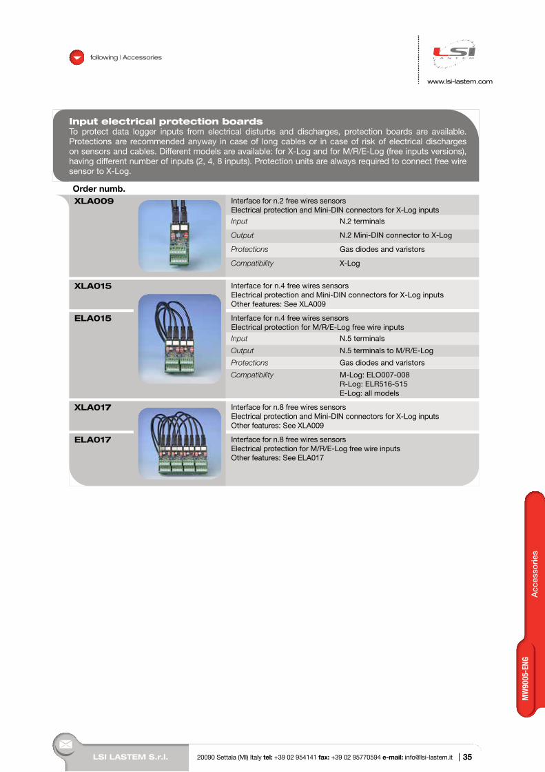
Input electrical protection boardsTo protect data logger inputs from electrical disturbs and discharges, protection boards are available. Protections are recommended anyway in case of long cables or in case of risk of electrical discharges on sensors and cables. Different models are available: for X-Log and for M/R/E-Log (free inputs versions), having different number of inputs (2, 4, 8 inputs). Protection units are always required to connect free wire sensor to X-Log.
Order numb.XLA009 Interface for n.2 free wires sensors
Electrical protection and Mini-DIN connectors for X-Log inputs
Input N.2 terminals
Output N.2 Mini-DIN connector to X-Log
Protections Gas diodes and varistors
Compatibility X-Log
XLA015 Interface for n.4 free wires sensors Electrical protection and Mini-DIN connectors for X-Log inputsOther features: See XLA009
ELA015 Interface for n.4 free wires sensorsElectrical protection for M/R/E-Log free wire inputs
Input N.5 terminals
Output N.5 terminals to M/R/E-Log
Protections Gas diodes and varistors
Compatibility M-Log: ELO007-008R-Log: ELR516-515E-Log: all models
XLA017 Interface for n.8 free wires sensorsElectrical protection and Mini-DIN connectors for X-Log inputsOther features: See XLA009
ELA017 Interface for n.8 free wires sensorsElectrical protection for M/R/E-Log free wire inputsOther features: See ELA017
35
MW
9005
-ENG
LSI LASTEM S.r.l. 20090 Settala (MI) Italy tel: +39 02 954141 fax: +39 02 95770594 e-mail: [email protected] |
following | Accessories
www.lsi-lastem.com
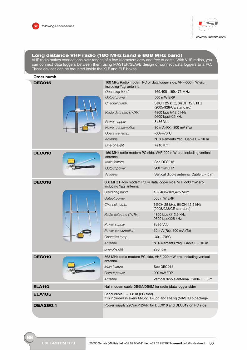
Long distance VHF radio (160 MHz band e 868 MHz band)VHF radio makes connections over ranges of a few kilometers easy and free of costs. With VHF radios, you can connect data loggers between them using MASTER/SLAVE design or connect data loggers to a PC. Those devices can be mounted inside the XLF and ELF boxes.
Order numb.DEC015 160 MHz Radio modem PC or data logger side, VHF-500 mW erp,
including Yagi antenna
Operating band 169.400÷169.475 MHz
Output power 500 mW ERP
Channel numb. 3@CH 25 kHz, 6@CH 12.5 kHz (2005/928/CE standard)
Radio data rate (Tx/Rx) 4800 bps @12.5 kHz 9600 bps@25 kHz
Power supply 8÷36 Vdc
Power consumption 30 mA (Rx), 300 mA (Tx)
Operative temp. -30÷+70°C
Antenna N. 3 elements Yagi. Cable L = 10 m
Line-of-sight 7÷10 Km
DEC010 160 MHz radio modem PC side, VHF-200 mW erp, including vertical antenna.
Main feature See DEC015
Output power 200 mW ERP
Antenna Vertical dipole antenna. Cable L = 5 m
DEC018 868 MHz Radio modem PC or data logger side, VHF-500 mW erp, including Yagi antenna
Operating band 169,400÷169,475 MHz
Output power 500 mW ERP
Channel numb. 3@CH 25 kHz, 6@CH 12,5 kHz (2005/928/CE standard)
Radio data rate (Tx/Rx) 4800 bps @12,5 kHz9600 bps@25 kHz
Power supply 8÷36 Vdc
Power consumption 30 mA (Rx), 300 mA (Tx)
Operative temp. -30÷+70°C
Antenna N. 6 elements Yagi. Cable L = 10 m
Line-of-sight 2÷3 Km
DEC019 868 MHz radio modem PC side, VHF-200 mW erp, including vertical antenna.
Main feature See DEC015
Output power 200 mW ERP
Antenna Vertical dipole antenna. Cable L = 5 m
ELA110 Null modem cable DB9M/DB9M for radio (data logger side)
ELA105 Serial cable L = 1.8 m (PC side). It is included in every M-Log, E-Log and R-Log (MASTER) package
DEA260.1 Power supply 220Vac/12Vdc for DEC010 and DEC019 on PC side
36
Acc
esso
ries
LSI LASTEM S.r.l. 20090 Settala (MI) Italy tel: +39 02 954141 fax: +39 02 95770594 e-mail: [email protected] |
following | Accessories
www.lsi-lastem.com
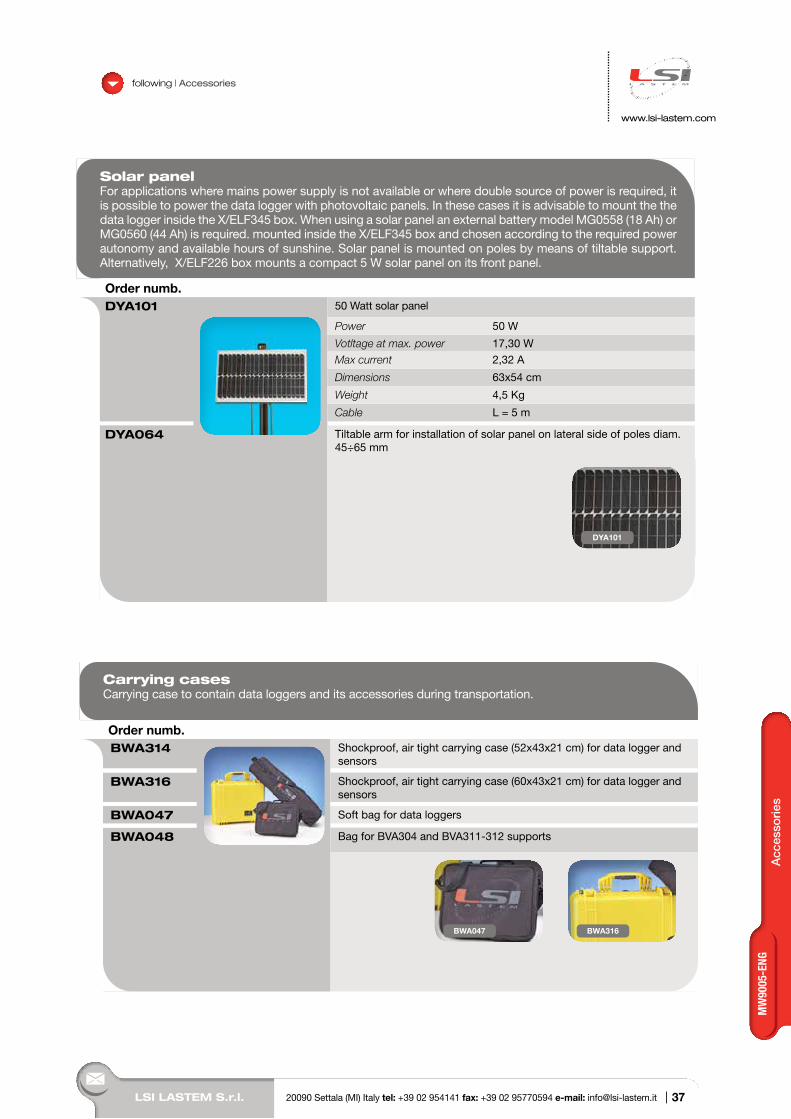
Solar panelFor applications where mains power supply is not available or where double source of power is required, it is possible to power the data logger with photovoltaic panels. In these cases it is advisable to mount the the data logger inside the X/ELF345 box. When using a solar panel an external battery model MG0558 (18 Ah) or MG0560 (44 Ah) is required. mounted inside the X/ELF345 box and chosen according to the required power autonomy and available hours of sunshine. Solar panel is mounted on poles by means of tiltable support. Alternatively, X/ELF226 box mounts a compact 5 W solar panel on its front panel.
Order numb.DYA101 50 Watt solar panel
Power 50 W
Votltage at max. power 17,30 W
Max current 2,32 A
Dimensions 63x54 cm
Weight 4,5 Kg
Cable L = 5 m
DYA064 Tiltable arm for installation of solar panel on lateral side of poles diam. 45÷65 mm
DYA101
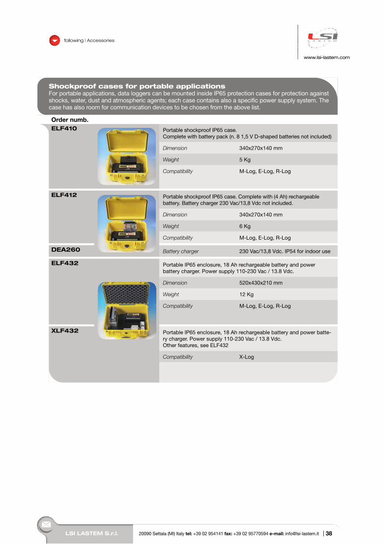
Carrying casesCarrying case to contain data loggers and its accessories during transportation.
Order numb.BWA314 Shockproof, air tight carrying case (52x43x21 cm) for data logger and
sensors
BWA316 Shockproof, air tight carrying case (60x43x21 cm) for data logger and sensors
BWA047 Soft bag for data loggers
BWA048 Bag for BVA304 and BVA311-312 supports
BWA047 BWA316
37
MW
9005
-ENG
LSI LASTEM S.r.l. 20090 Settala (MI) Italy tel: +39 02 954141 fax: +39 02 95770594 e-mail: [email protected] |
Shockproof cases for portable applications For portable applications, data loggers can be mounted inside IP65 protection cases for protection against shocks, water, dust and atmospheric agents; each case contains also a specific power supply system. The case has also room for communication devices to be chosen from the above list.
Order numb.ELF410 Portable shockproof IP65 case.
Complete with battery pack (n. 8 1,5 V D-shaped batteries not included)
Dimension 340x270x140 mm
Weight 5 Kg
Compatibility M-Log, E-Log, R-Log
ELF412 Portable shockproof IP65 case. Complete with (4 Ah) rechargeable battery. Battery charger 230 Vac/13,8 Vdc not included.
Dimension 340x270x140 mm
Weight 6 Kg
Compatibility M-Log, E-Log, R-Log
DEA260 Battery charger 230 Vac/13,8 Vdc. IP54 for indoor use
ELF432 Portable IP65 enclosure, 18 Ah rechargeable battery and power battery charger. Power supply 110-230 Vac / 13.8 Vdc.
Dimension 520x430x210 mm
Weight 12 Kg
Compatibility M-Log, E-Log, R-Log
XLF432 Portable IP65 enclosure, 18 Ah rechargeable battery and power batte-ry charger. Power supply 110-230 Vac / 13.8 Vdc.Other features, see ELF432
Compatibility X-Log
following | Accessories
www.lsi-lastem.com
38
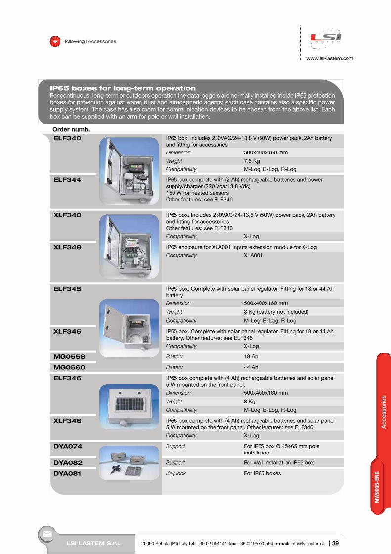
Acc
esso
ries
LSI LASTEM S.r.l. 20090 Settala (MI) Italy tel: +39 02 954141 fax: +39 02 95770594 e-mail: [email protected] |
following | Accessories
www.lsi-lastem.com
IP65 boxes for long-term operationFor continuous, long-term or outdoors operation the data loggers are normally installed inside IP65 protection boxes for protection against water, dust and atmospheric agents; each case contains also a specific power supply system. The case has also room for communication devices to be chosen from the above list. Each box can be supplied with an arm for pole or wall installation.
Order numb.ELF340 IP65 box. Includes 230VAC/24-13,8 V (50W) power pack, 2Ah battery
and fitting for accessories
Dimension 500x400x160 mm
Weight 7,5 Kg
Compatibility M-Log, E-Log, R-Log
ELF344 IP65 box complete with (2 Ah) rechargeable batteries and power supply/charger (220 Vca/13,8 Vdc)150 W for heated sensorsOther features: see ELF340
XLF340 IP65 box. Includes 230VAC/24-13,8 V (50W) power pack, 2Ah battery and fitting for accessories.Other features: see ELF340
Compatibility X-Log
XLF348 IP65 enclosure for XLA001 inputs extension module for X-Log
Compatibility XLA001
ELF345 IP65 box. Complete with solar panel regulator. Fitting for 18 or 44 Ah battery
Dimension 500x400x160 mm
Weight 8 Kg (battery not included)
Compatibility M-Log, E-Log, R-Log
XLF345 IP65 box. Complete with solar panel regulator. Fitting for 18 or 44 Ah battery. Other features: see ELF345
Compatibility X-Log
MG0558 Battery 18 Ah
MG0560 Battery 44 Ah
ELF346 IP65 box complete with (4 Ah) rechargeable batteries and solar panel 5 W mounted on the front panel.
Dimension 500x400x160 mm
Weight 8 Kg
Compatibility M-Log, E-Log, R-Log
XLF346 IP65 box complete with (4 Ah) rechargeable batteries and solar panel 5 W mounted on the front panel. Other features: see ELF346
Compatibility X-Log
DYA074 Support For IP65 box Ø 45÷65 mm pole installation
DYA082 Support For wall installation IP65 box
DYA081 Key lock For IP65 boxes
39
MW
9005
-ENG
40
>> d
ata
LO
GG
ER
S
via Ex SP. 161 Dosso, 9 20090 Settala (MI) Italy tel: +39 02 95 41 41 fax: +39 02 95 77 05 94e-mail: [email protected] web site: www.lsi-lastem.com
1
2
3
4
5
6
7
8
MilanoITALY
adresses and contacts
1
2
3
4