Data logger - LSI LASTEM · 2020-04-03 · LSI LASTEM Data logger – Communication protocols 4 1....
25
INSTUM_00728_en Data logger Communication protocols Updated on 28 May 2018
Transcript of Data logger - LSI LASTEM · 2020-04-03 · LSI LASTEM Data logger – Communication protocols 4 1....

INSTUM_00728_en
Data logger
Communication protocols
Updated on 28 May 2018
LSI LASTEM Data logger – Communication protocols
2
Copyright 2010-2018 LSI LASTEM. All rights reserved.
The information contained in this manual may be changed without prior notification.
No part of this manual may be reproduced, neither electronically or mechanically, under any circumstance, without the
prior written permission of LSI LASTEM.
LSI LASTEM reserves the right to carry out changes to this product without timely updating this document.

LSI LASTEM Data logger – Communication protocols
3
Index
1. Introduction .................................................................................................................................. 4
2. TTY protocol................................................................................................................................ 4 2.1. Messages description ........................................................................................................... 4 2.2. Request message format....................................................................................................... 4
2.2.1. Instrument time adjust .................................................................................................. 5 2.3. Responce messages format .................................................................................................. 5
2.3.1. Calculation of checksum field ...................................................................................... 5 2.3.2. Simple confirmation answer ........................................................................................ 6 2.3.3. Instantaneous values .................................................................................................... 6 2.3.4. Registry information .................................................................................................... 6 2.3.5. Statistic and diagnotic data .......................................................................................... 7
3. Modbus protocol .......................................................................................................................... 8 3.1. Messages format .................................................................................................................. 8
3.1.1. Address......................................................................................................................... 8 3.1.2. Function code ............................................................................................................... 9 3.1.3. CRC16 .......................................................................................................................... 9
3.2. Supported functions ............................................................................................................. 9
3.2.1. Read Coils .................................................................................................................... 9 3.2.2. Read Holding Registers ............................................................................................. 12
3.2.3. Read Input Registers .................................................................................................. 12 3.2.4. Write Single Coil ....................................................................................................... 17 3.2.5. Write Multiple Coils .................................................................................................. 19
3.2.6. Write Multiple Registers ............................................................................................ 20 3.2.7. Read Device Identification ......................................................................................... 22
3.3. Exception codes ................................................................................................................. 24 3.4. Master mode ....................................................................................................................... 25

LSI LASTEM Data logger – Communication protocols
4
1. Introduction
E-Log and M-Log data loggers supports some different communication protocols accessible from
two serial ports. This manual describes the TTY and Modbus protocols on serial port 2.
2. TTY protocol
Using TTY protocol the instrument can be queried to obtainin, in a very simple way, probe
measurements and derived calculations (instantaneous values) and other useful information. The
request of the measured values takes place in polling mode (by host command), or spontaneous
mode with programmable transmission rate.
Data is transmitted in a format easy to decode, either directly by the operator using the terminal
program, both by decoder or auto-import programs.
The query message contains the network address of the queried device; this allow to query different
data loggers connected on a single communications line.
2.1. Messages description
In the following descriptions will be used < and > characters to delimit the various fields that make
up the request and response messages. Keep in mind that these characters are used herein for
descriptive purposes and are thus not in real messages exchanged during the communication.
2.2. Request message format
Following characters sequence is needed to query the data logger:
<A><addr><cmd><prm><CR>
where:
<A>: ASCII ‘A’ character (Hexadecimal 41);
<addr>: Instrument’s address, expressed by ASCII character from ‘1’ (Hexadecimal 31) to ‘9’
(Hexadecimal 39); the instrument answers only if the 3DOM programmed address inside the data
logger (network address parameter) match this value;
<cmd>: command code; ASCII character among:
• <I>: inquiry of the measure’s instantaneous value;
• <S>: inquiry of instrument’s registry information;
• <T>: time adjust (E-Log support this command from version 2.01.04);
• <A>: starts the spontaneous transmission of the instantaneous data; the data logger starts the
transmission of measure’s instantaneous data using temporal rate configured through 3DOM
program; if programmed value is zero, this command enters the automatic sending mode
with fixed transmission rate of 10 seconds; in case of instrument restart, the automatism
LSI LASTEM Data logger – Communication protocols
5
isn’t restarted; in order to obtain the automatic transmission (also after the instrument’s
restart) setup with 3DOM automatic sending time ≠ 0;
• <M>: stops the spontaneous transmission of the instantaneous data; if the instrument is
restarted from power off, it starts again the automatic data transmission, but only if sending
time is programmed ≠ 0;
• <D>: inquiry of the diagnostic and statistic data regarding the instrument operation;
• <R>: Zero setting of the instrument-operation’s diagnostic and statistic data; please note that
the zero setting includes the answer data sent to <D> command, and the zeroing of all others
statistic information (displayed by the diagnostic windows, for more information refer to the
manual of the instrument in use).
<prm>: optional request parameters.
<CR>: ASCII character carriage return.
Note: when the data logger is restarted it starts the automatic spontaneous data transmission only in
case the transmission rate has been setup with a value ≠ 0, without the need to use the command
<A>.
All above mentioned commands must be sent in a complete sequence, not interrupted by data
automatically transmitted by the data logger, otherwise the instrument isn’t able to identify the sent
command.
2.2.1. Instrument time adjust
Time inside the data logger can be adjusted with a message like this:
<addr><T><P¦I><yy/mm/dd hh:mm:ss>
where:
<P¦I>:“P” set the data logger to adjust progressively the time indicated in the message, while “I”
set the time in immediate way;
<yy/mm/dd hh:mm:ss> date and time to be set in the data logger; the numeric sequence must
be respected, but separator characters between fields can be any not numeric character.
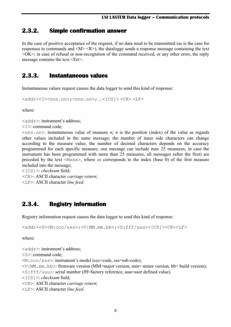
2.3. Responce messages format
2.3.1. Calculation of checksum field
Each response message containing data prepared by the instrument includes, as appendix, a
transmission check control code (checksum), useful for validating the data received from those
actually transmitted.
The checksum field is enclosed in square brackets; it is expressed in hexadecimal and ASCII, which
is the sum to 8-bit exclusive OR of all characters between the first character and the character
immediately preceding the left bracket.
LSI LASTEM Data logger – Communication protocols
6
2.3.2. Simple confirmation answer
In the case of positive acceptance of the requent, if no data need to be transmitted (as is the case for
responses to commands and <M> <R>), the datalogge sends a response message containing the text
<OK>; in case of refusal or non-recognition of the command received, or any other error, the reply
message contains the text <Err>.
2.3.3. Instantaneous values
Instantaneous values request causes the data logger to send this kind of response:
<addr><I><nnn.nn>;<nnn.nn>;…<[CS]> <CR> <LF>
where:
<addr>: instrument’s address;
<I>: command code;
<nnn.nn>: instantaneous value of measure n; n is the position (index) of the value as regards
other values included in the same message; the number of inner side characters can change
according to the measure value; the number of decimal characters depends on the accuracy
programmed for each specific measure; one message can include max 25 measures; in case the
instrument has been programmed with more than 25 measures, all messages (after the first) are
preceded by the text <Mxxx>, where xx corresponds to the index (base 0) of the first measure
included into the message;
<[CS]>: checksum field;
<CR>: ASCII character carriage return;
<LF>: ASCII character line feed.
2.3.4. Registry information
Registry information request causes the data logger to send this kind of response:
<addr><S><M:ccc/sss>;<V:MM.mm.bb>;<S:fff/uuu><[CS]><CR><LF>
where:
<addr>: instrument’s address;
<S>: command code;
<M:ccc/sss>: instrument’s model (ccc=code, sss=sub-code);
<V:MM.mm.bb>: firmware version (MM=major version, mm= minor version, bb= build version);
<S:fff/uuu>: serial number (fff=factory reference, uuu=user defined value).
<[CS]>: checksum field;
<CR>: ASCII character carriage return;
<LF>: ASCII character line feed.

LSI LASTEM Data logger – Communication protocols
7
2.3.5. Statistic and diagnotic data
<addr><D><L:lll>;<S:sss>;<C:ccc>;<E:eee><[CS]><CR><LF>
where:
<addr>: instrument’s address;
<D>: command code;
<L:lll>: instrument continuous operation time (lifetime), written as ddd hh:mm:ss;
<S:sss>: date/time of last zero setting of the statistic data, written as yy/mm/dd hh:mm:ss;
<C:ccc>: system date/hour of the instrument, written yy/mm/dd hh:mm:ss;
<E:eee>: hexadecimal code of operation errors found by the instrument (for more information
refer to the manual of the instrument in use);
<[CS]>: checksum field;
<CR>: ASCII character carriage return;
<LF>: ASCII character line feed.

LSI LASTEM Data logger – Communication protocols
8
3. Modbus protocol
Modbus is a serial communication protocol widely used in industry to enable communication
between a master (usually a PCor a SCADA system) and one or more slaves (measuring
instruments, control or PLC), connected on the same network. Modbus defines how the master and
slave establish and interrupt the communication, how messages are exchanged and how errors are
detected. Only the master can initiate the communication.
Each network device is assigned a unique address. A Modbus command contains the address of the
destination device which the message is direct to. Only the addressed device will respond to the
command, although other instruments are receiving the same message. All Modbus commands
contain checking information, ensuring that the command arrived is correct.
From Modbus point of view the data logger is configured in the system either as master or slave
and implements the protocol in RTU version.
The data logger is able to communicate via serial with other devices that support the parity set to
None.
3.1. Messages format
Master/slave devices use following messages format:
Field name Dimension Description
Address 1 byte The master must communicate with this slave address
(instrument network address); broadcast (ID = 0) message
isn’t supported
Function code 1 byte Command to run (or executed)
Data n bytes Data payload
CRC16 2 bytes Error check according to CRC16 algorithm
If slave device finds an error in received message (format error or error in CRC16), this message is
considered like non-valid and it’s rejected; therefore the command isn’t run. The same happens
when the address doesn’t correspond to considered device.
3.1.1. Address
The address is used to identify the message’s receiver: it includes the numeric address of selected
slave. The address can have values from 1 to 200 if used in RS-232 network. The instrument
compares the value of received address with programmed network address, and it answers only if
both match. Use 3DOM application to change the network address.
Broadcast messages (address = 0) aren’t supported.
LSI LASTEM Data logger – Communication protocols
9
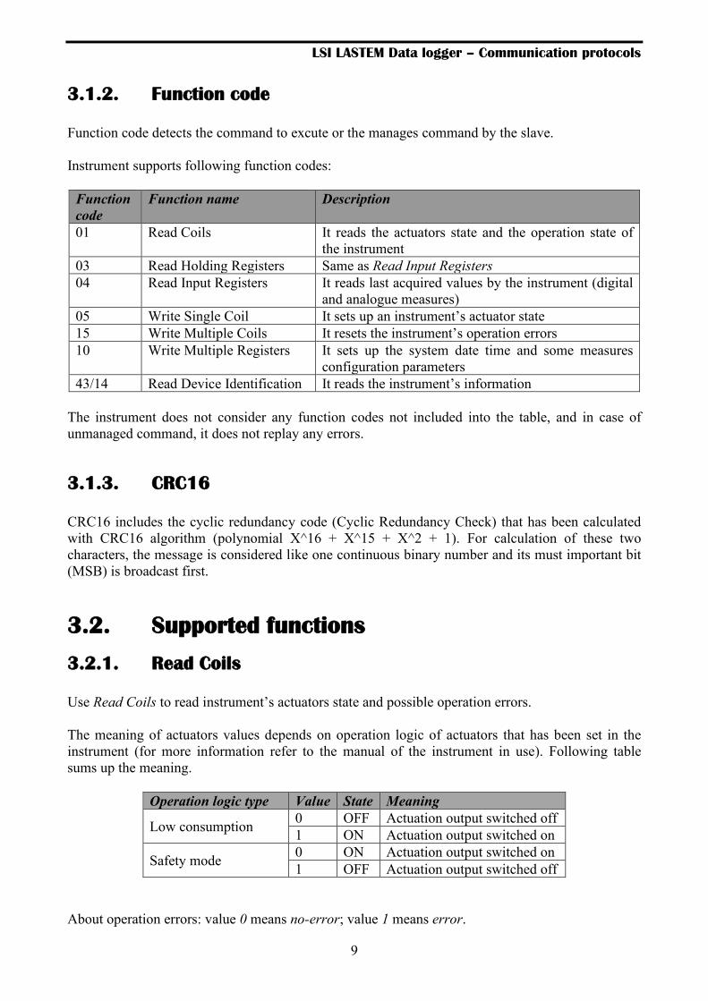
3.1.2. Function code
Function code detects the command to excute or the manages command by the slave.
Instrument supports following function codes:
Function
code
Function name Description
01 Read Coils It reads the actuators state and the operation state of
the instrument
03 Read Holding Registers Same as Read Input Registers
04 Read Input Registers It reads last acquired values by the instrument (digital
and analogue measures)
05 Write Single Coil It sets up an instrument’s actuator state
15 Write Multiple Coils It resets the instrument’s operation errors
10 Write Multiple Registers It sets up the system date time and some measures
configuration parameters
43/14 Read Device Identification It reads the instrument’s information
The instrument does not consider any function codes not included into the table, and in case of
unmanaged command, it does not replay any errors.
3.1.3. CRC16
CRC16 includes the cyclic redundancy code (Cyclic Redundancy Check) that has been calculated
with CRC16 algorithm (polynomial X^16 + X^15 + X^2 + 1). For calculation of these two
characters, the message is considered like one continuous binary number and its must important bit
(MSB) is broadcast first.
3.2. Supported functions
3.2.1. Read Coils
Use Read Coils to read instrument’s actuators state and possible operation errors.
The meaning of actuators values depends on operation logic of actuators that has been set in the
instrument (for more information refer to the manual of the instrument in use). Following table
sums up the meaning.
Operation logic type Value State Meaning
Low consumption 0 OFF Actuation output switched off
1 ON Actuation output switched on
Safety mode 0 ON Actuation output switched on
1 OFF Actuation output switched off
About operation errors: value 0 means no-error; value 1 means error.

LSI LASTEM Data logger – Communication protocols
10
Address
(Hex) Coil Meaning
Actuators state
0x00 01
02
03
04
05
06
07
08
Actuator nr. 1 state
Actuator nr. 2 state
Actuator nr. 3 state
Actuator nr. 4 state
Actuator nr. 5 state
Actuator nr. 6 state
Actuator nr. 7 state
Not used
Operation state (errors)
0x01 09
10
11
12
13
14
15
16
Error Read After Write
Saved configuration not-valid
Search error of storage page
Max loop Nr. exceeded during stored data search
Overrun acceptance queue acquisition request
Overrun storage queue acquisition results
Not used
Failed page writing in store
0x02 17
18
19
20
21
22
23
24
One or more pages of processing data lost
Failed deleting store sector
Timeout about waiting operation stop in store
Store device not supported
Wrong received message (check code not valid)
Message repeated up to 3 times max.
Message has been deleted owing to max repeat
Error deleted during writing/reading of EEProm slave inside
0x03 25
26
27
28
29
30
31
32
Slave cannot operate because configuration hasn’t been programmed
Overflow reception of single message
Messages queue full in slave
All CISS errors about syntax
CISS Error not specified (Unspecified)
CISS Error (BadCommandCode)
CISS Error (BadParameter)
CISS Error (ParameterOutOfRange)
0x04 33
34
35
36
37
38
39
40
CISS Error (UnrecognizedCDV)
CISS Error (BeyondMaxClassLevel)
CISS Error (ParameterIndexOutOfRange)
CISS Error (ClassIndexOutOfRange)
CISS Error (RequestNotPermitted)
Not used
Not used
Not used
LSI LASTEM Data logger – Communication protocols
11
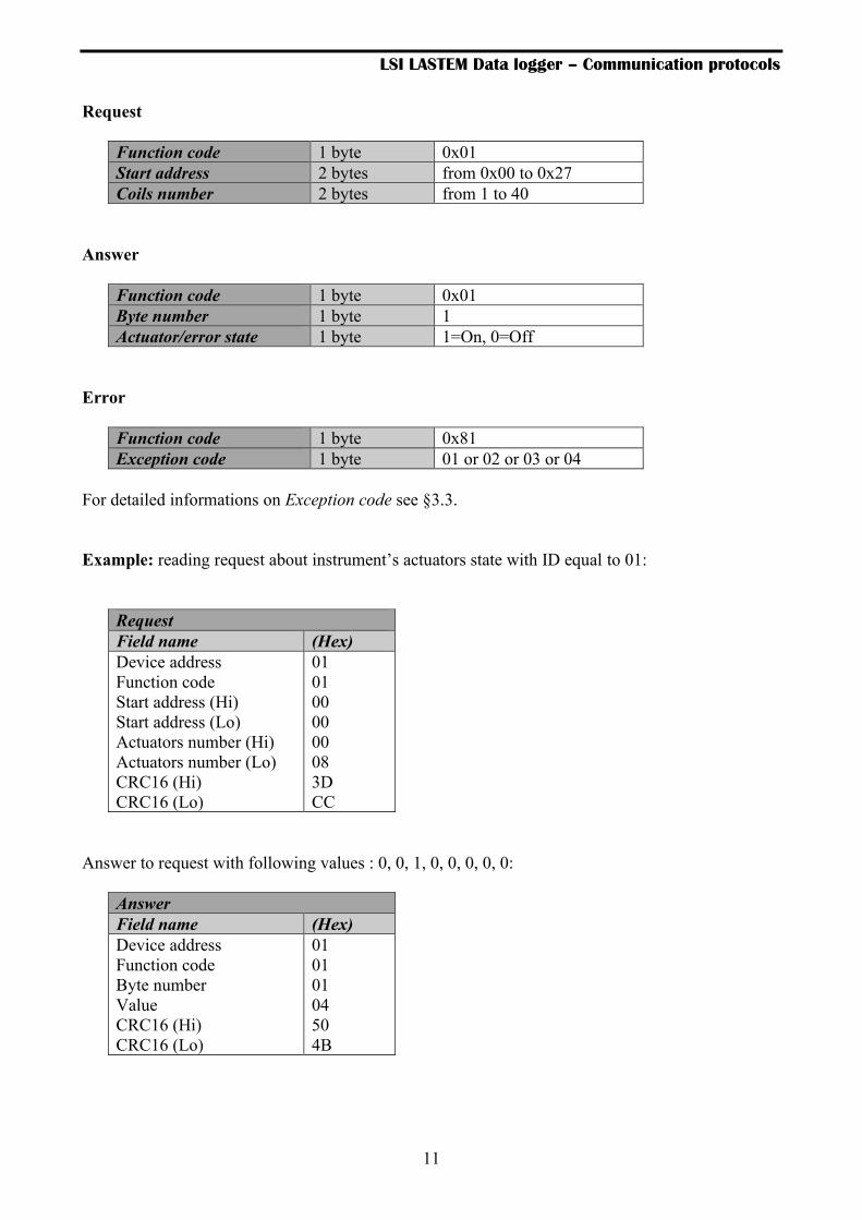
Request
Function code 1 byte 0x01
Start address 2 bytes from 0x00 to 0x27
Coils number 2 bytes from 1 to 40
Answer
Function code 1 byte 0x01
Byte number 1 byte 1
Actuator/error state 1 byte 1=On, 0=Off
Error
Function code 1 byte 0x81
Exception code 1 byte 01 or 02 or 03 or 04
For detailed informations on Exception code see §3.3.
Example: reading request about instrument’s actuators state with ID equal to 01:
Request
Field name (Hex)
Device address
Function code
Start address (Hi)
Start address (Lo)
Actuators number (Hi)
Actuators number (Lo)
CRC16 (Hi)
CRC16 (Lo)
01
01
00
00
00
08
3D
CC
Answer to request with following values : 0, 0, 1, 0, 0, 0, 0, 0:
Answer
Field name (Hex)
Device address
Function code
Byte number
Value
CRC16 (Hi)
CRC16 (Lo)
01
01
01
04
50
4B

LSI LASTEM Data logger – Communication protocols
12
3.2.2. Read Holding Registers
Read Holding Register and Read Input Register are similar. In the Request use 0x03 funcition code
for the first case and 0x04 for the second.
For more information, see Read Input Register explanation command.
3.2.3. Read Input Registers
Use the function Read Input Registers to read last values acquired by the instrument, both analogue
and digital measures, and the system date time. Acquired values can be read in numeric floating-
point format by requesting them from the address 0 (0x0000) and in integer format from the address
1000 (0x03E8) while the date time from the address 2000 (0x07D0).
The address to set for each request is as follows:
Address (Hex) Registers number Meaning
Float values ( IEEE754 format)
0x0000 2 Measure value 1
0x0002 2 Measure value 2
… … …
0x00C4 2 Measure value 99
Integer values (WORD format)
0x03E8 1 Measure value 1
0x03E9 1 Measure value 2
… … …
0x044B 1 Measure value 99
System date time (yy MM dd hh mm ss)
0x07D0 1 yy MM
0x07D1 1 dd hh
0x07D2 1 mm ss
Floating point values
Each measure value transmitted in floating point format required 4 byte, so it uses 2 Modbus
registers. Floating point values are expressed as indicated in the IEEE754 norm.
Through program 3DOM it’s possible select the data format between Big Endian (default value)
and Little Endian. In the first case the data storage starts from most significant byte (MSB) while in
the second case it starts from less significant byte (LSB). i.e. the value 11,0 is stored from the
address 0x20 like follow:

LSI LASTEM Data logger – Communication protocols
13
Memory Address
(Hex)
Format value
Big Endian (Hex)
Format value
Little Endian (Hex)
…
Value 11,0
Register 1 Byte 1 0x20 00 30
Byte 2 0x21 00 41
Register 2 Byte 1 0x22 41 00
Byte 2 0x23 30 00
…
As the frame consists of 255 characters, it is possible to transmit max 60 measures for each request
message. It is necessary arrange two requests to obtain all 99 measures.
Value -999999 (0xF02374C9), unless otherwise noted (see §3.2.6), corresponds to measure in
error.
Request
Function code 1 byte 0x04
Start address 2 bytes from 0x0000 to 0x00C4
Registers number 2 bytes from 2 to 198 (max 120)
Answer
Function code 1 byte 0x04
Byte number 1 byte 2 x N*
Value 2 bytes x N*
*N = Measures number.
Error
Function code 1 byte 0x84
Exception code 1 byte 01 o 02 o 03 o 04
For detailed informations on Exception code see §3.3.
Data Area
# Measure 1 2 3 4 5 6 … 99
Address (hex) 0x00 0x02 0x04 0x06 0x08 0x0A … 0x0C4
LSI LASTEM Data logger – Communication protocols
14
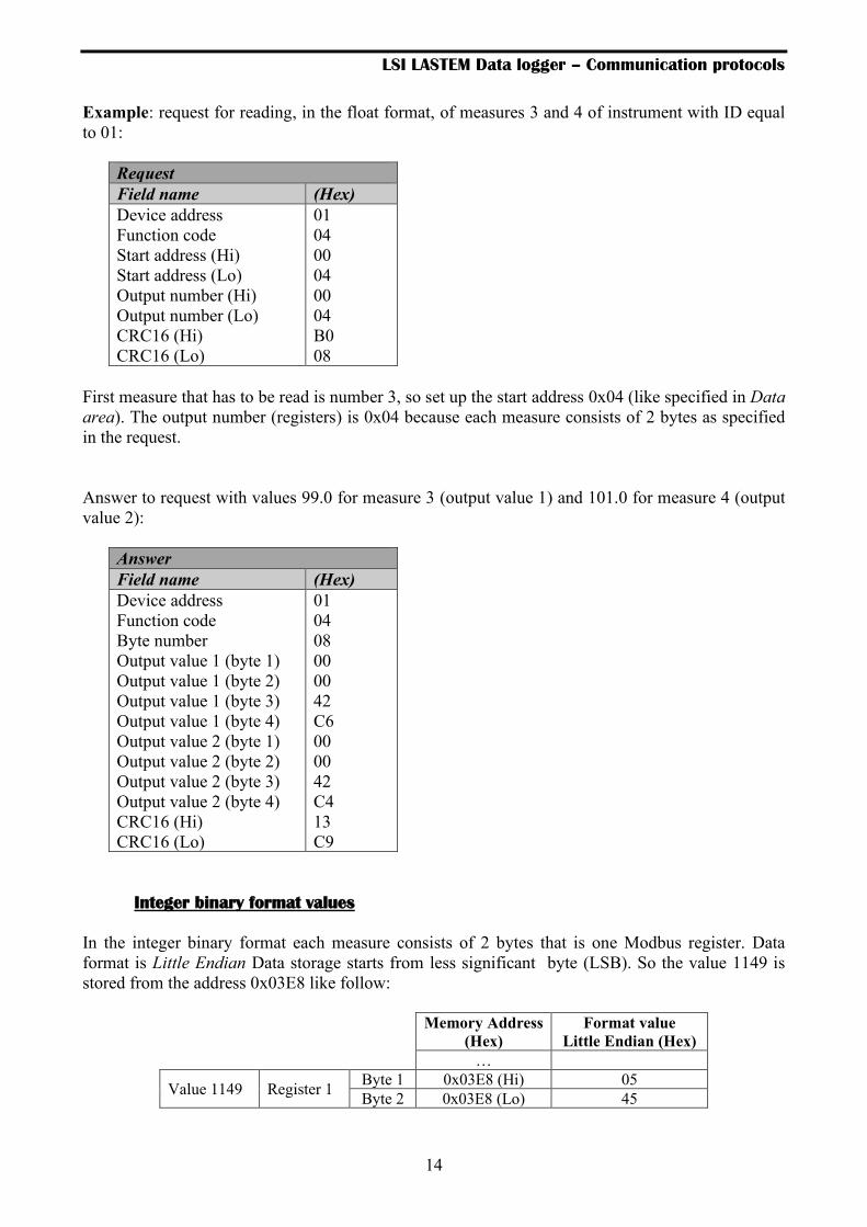
Example: request for reading, in the float format, of measures 3 and 4 of instrument with ID equal
to 01:
Request
Field name (Hex)
Device address
Function code
Start address (Hi)
Start address (Lo)
Output number (Hi)
Output number (Lo)
CRC16 (Hi)
CRC16 (Lo)
01
04
00
04
00
04
B0
08
First measure that has to be read is number 3, so set up the start address 0x04 (like specified in Data
area). The output number (registers) is 0x04 because each measure consists of 2 bytes as specified
in the request.
Answer to request with values 99.0 for measure 3 (output value 1) and 101.0 for measure 4 (output
value 2):
Answer
Field name (Hex)
Device address
Function code
Byte number
Output value 1 (byte 1)
Output value 1 (byte 2)
Output value 1 (byte 3)
Output value 1 (byte 4)
Output value 2 (byte 1)
Output value 2 (byte 2)
Output value 2 (byte 3)
Output value 2 (byte 4)
CRC16 (Hi)
CRC16 (Lo)
01
04
08
00
00
42
C6
00
00
42
C4
13
C9
Integer binary format values
In the integer binary format each measure consists of 2 bytes that is one Modbus register. Data
format is Little Endian Data storage starts from less significant byte (LSB). So the value 1149 is
stored from the address 0x03E8 like follow:
Memory Address
(Hex)
Format value
Little Endian (Hex)
…
Value 1149 Register 1 Byte 1 0x03E8 (Hi) 05
Byte 2 0x03E8 (Lo) 45

LSI LASTEM Data logger – Communication protocols
15
Until E-Log V. 2.36.01 and M-Log V. 2.15.00, in order not to loose the decimal part of the
measure, an offset and gain can be applied to each reading, by setting respectively Mathematical
constant 1 and Mathematical constant 2 of the standard parameters with the program 3DOM. Thus,
for example, having set an offset of 0 and a gain of 100, the reading 11.49 would become (11.49 +
0) * 100 = 1149. To obtain the correct value, the received measure must be divided by the gain and
subtracted to the offset. From later program version this operation is done based on the precision of
the measure. The reading 23.45 with two decimals value would became 2345 while the reading 68.4
with one decimal value would became 684.
Unlike to the float format, for the integer type it is possible to obtain all the 99 measures, which the
data logger is capable, in a single request.
A value of -1 (0xFFFF), unless otherwise set (see §3.2.6), corresponds to measure error value.
Request
Function code 1 byte 0x04
Address Start 2 bytes da 0x03E8 a 0x044B
Coil Number 2 bytes da 1 a 99
Answer
Function code 1 byte 0x04
Byte number 1 byte 2 x N*
Actuator/error state 2 bytes x N*
*N = measures number.
Error
Function code 1 byte 0x84
Exception code 1 byte 01 o 02 o 03 o 04
For detailed informations on Exception code see §3.3.
Data area
# Measure 1 2 3 4 … 99
Address (hex) 0x03E8 0x03E9 0x03EA 0x03EB … 0x044B

LSI LASTEM Data logger – Communication protocols
16
Example: request for reading, in the integer format, of measure 3 of instrument with ID equal to 01:
Request
Field name (Hex)
Device address
Function code
Start address (Hi)
Start address (Lo)
Output number (Hi)
Output number (Lo)
CRC16 (Hi)
CRC16 (Lo)
01
04
03
EA
00
01
A5
BA
The measure that has to be read is number 3, so set up the start address 0x03EA (like specified in
Data area). The output number (register) is 0x01 because the measure consists of 1 byte like
specified in the request.
Answer to request with value 1343:
Answer
Field name (Hex)
Device address
Function code
Byte number
Output value 1 (byte 1)
Output value 1 (byte 2)
CRC16 (Hi)
CRC16 (Lo)
01
04
02
05
3F
FB
04
System date time
Request
Function code 1 byte 0x04
Start address 2 bytes da 0x07D0 a 0x07D2
Registers number 2 bytes da 1 a 3
Answer
Function code 1 byte 0x04
Byte number 1 byte 2 x N*
Value 2 bytes x N*
*N = Measures number.
The sequence of date/time fields starting from address 0x07D0 is: yy MM dd hh mm ss.
LSI LASTEM Data logger – Communication protocols
17
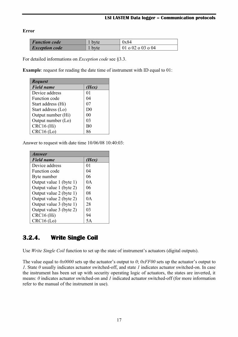
Error
Function code 1 byte 0x84
Exception code 1 byte 01 o 02 o 03 o 04
For detailed informations on Exception code see §3.3.
Example: request for reading the date time of instrument with ID equal to 01:
Request
Field name (Hex)
Device address
Function code
Start address (Hi)
Start address (Lo)
Output number (Hi)
Output number (Lo)
CRC16 (Hi)
CRC16 (Lo)
01
04
07
D0
00
03
B0
86
Answer to request with date time 10/06/08 10:40:03:
Answer
Field name (Hex)
Device address
Function code
Byte number
Output value 1 (byte 1)
Output value 1 (byte 2)
Output value 2 (byte 1)
Output value 2 (byte 2)
Output value 3 (byte 1)
Output value 3 (byte 2)
CRC16 (Hi)
CRC16 (Lo)
01
04
06
0A
06
08
0A
28
03
94
5A
3.2.4. Write Single Coil
Use Write Single Coil function to set up the state of instrument’s actuators (digital outputs).
The value equal to 0x0000 sets up the actuator’s output to 0; 0xFF00 sets up the actuator’s output to
1. State 0 usually indicates actuator switched-off, and state 1 indicates actuator switched-on. In case
the instrument has been set up with security operating logic of actuators, the states are inverted, it
means: 0 indicates actuator switched-on and 1 indicated actuator switched-off (for more information
refer to the manual of the instrument in use).

LSI LASTEM Data logger – Communication protocols
18
Request
Function code 1 byte 0x05
Start address 2 bytes from 0x0000 to 0x0007
Value 2 bytes 0x0000 or 0xFF00
Answer
Function code 1 byte 0x01
Start address 2 bytes from 0x0000 to 0x0007
Value 2 bytes 0x0000 or 0xFF00
Error
Function code 1 byte 0x85
Exception code 1 byte 01 or 02 or 03 or 04
For detailed informations on Exception code see §3.3.
Example: request to set up to 0 the state of actuator number 3 of the instrument with ID equal to 01:
Request
Field name (Hex)
Device address
Function code
Start address (Hi)
Start address (Lo)
Value (Hi)
Value (Lo)
CRC16 (Hi)
CRC16 (Lo)
01
05
00
02
00
00
6C
0A
Answer
Device address (Hex)
Device address
Function code
Start address (Hi)
Start address (Lo)
Value (Hi)
Value (Lo)
CRC16 (Hi)
CRC16 (Lo)
01
05
00
02
00
00
6C
0A
LSI LASTEM Data logger – Communication protocols
19
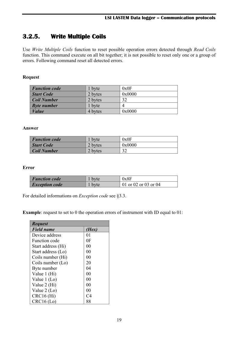
3.2.5. Write Multiple Coils
Use Write Multiple Coils function to reset possible operation errors detected through Read Coils
function. This command execute on all bit together; it is not possible to reset only one or a group of
errors. Following command reset all detected errors.
Request
Function code 1 byte 0x0F
Start Code 2 bytes 0x0000
Coil Number 2 bytes 32
Byte number 1 byte 4
Value 4 bytes 0x0000
Answer
Error
Function code 1 byte 0x8F
Exception code 1 byte 01 or 02 or 03 or 04
For detailed informations on Exception code see §3.3.
Example: request to set to 0 the operation errors of instrument with ID equal to 01:
Request
Field name (Hex)
Device address
Function code
Start address (Hi)
Start address (Lo)
Coils number (Hi)
Coils number (Lo)
Byte number
Value 1 (Hi)
Value 1 (Lo)
Value 2 (Hi)
Value 2 (Lo)
CRC16 (Hi)
CRC16 (Lo)
01
0F
00
00
00
20
04
00
00
00
00
C4
88
Function code 1 byte 0x0F
Start Code 2 bytes 0x0000
Coil Number 2 bytes 32

LSI LASTEM Data logger – Communication protocols
20
Answer
Nome campo (Hex)
Device address
Function code
Start address (Hi)
Start address (Lo)
Coils number (Hi)
Coisl number (Lo)
CRC16 (Hi)
CRC16 (Lo)
01
0F
00
00
00
20
21
79
3.2.6. Write Multiple Registers
Use Write Multiple Registers function to set the system date time and some measures configuration
parameters.
The address to set for each request is as follows:
Address (Hex) Registers number Meaning
System date time (yy mm dd hh mm ss)
0x07D0 3 yy mm dd hh mm ss
Measure configuration
0x07DA 5 Value used for measurement error in the
decimal binary and floating point type, measure
enable (up to max 32)
The configuration parameters of the measure that can be changed are:
• Value to assign to the measure when it is in error in the WORD format (2 bytes = 1
register);
• Value to assign to the measure when it is in error in the float format (4 bytes = 2 register);
use Little Endian format;
• Measure enabled status (one bit for each activation status of the measure for a maximum of
32 measures (4 bytes = 2 registers); the measure not enabled will be considered in error.
These parameters are stored permanently until they are reset or until the next reconfiguration of the
instrument by 3DOM. In this case they are set with default values: -1 for binary decimal values, -
999999 for floating point values, all measures enabled.

LSI LASTEM Data logger – Communication protocols
21
Example 1: request to set the system date time to 09/06/10 16:03:05 (yy/mm/dd hh:mm:ss format):
Request
Field name (Hex)
Device address
Function code
Start address (Hi)
Start address (Lo)
Registers number (Hi)
Registers number (Lo)
Byte number
Value 1 (Hi)
Value 1 (Lo)
Value 2 (Hi)
Value 2 (Lo)
Value 3 (Hi)
Value 3 (Lo)
CRC16 (Hi)
CRC16 (Lo)
01
10
07
D0
00
03
06
0A
06
09
10
03
05
B2
5D
Answer
Field name (Hex)
Device address
Function code
Start address (Hi)
Start address (Lo)
Coils number (Hi)
Coils number (Lo)
CRC16 (Hi)
CRC16 (Lo)
01
10
07
D0
00
03
80
85

LSI LASTEM Data logger – Communication protocols
22
Example 2: request to set the measures parameters with the following values: -12345 (0xCFC7) for
measure in error for binary decimal type, -12345678 (0x4E613CCB) for measure in error for float
type and all measures disabled except the first 3:
Request
Field name (Hex)
Device address
Function code
Start address (Hi)
Start address (Lo)
Registers number (Hi)
Registers number (Lo)
Byte number
Value 1 (Hi)
Value 1 (Lo)
Value 2 (Hi)
Value 2 (Lo)
Value 3 (Hi)
Value 3 (Lo)
Value 4 (Hi)
Value 4 (Lo)
Value 5 (Hi)
Value 5 (Lo)
CRC16 (Hi)
CRC16 (Lo)
01
10
07
DA
00
05
0A
C7
CF
4E
61
3C
CB
07
00
00
00
6C
11
Request
Field name (Hex)
Device address
Function code
Start address (Hi)
Start address (Lo)
Coils number (Hi)
Coisl number (Lo)
CRC16 (Hi)
CRC16 (Lo)
01
10
07
DA
00
05
20
85
3.2.7. Read Device Identification
Use Read Device Identification to get information about instrument, i.e.: producing company name,
type, code, serial number and instrument model.
Request
Function code 1 byte 0x2B
MEI type 1 byte 0x0E
Id code device reading 1 byte 01
Id object 1 byte 0x00

LSI LASTEM Data logger – Communication protocols
23
Answer
Function code 1 byte 0x2B
MEI*type 1 byte 0x0E
Id code device reading 1 byte 01
Compliance level 1 byte 0x01
Follow 1 byte 0
Next object Id 1 byte Object Id number
Objects number 1 byte 3
Object 1 Id 1 byte 0
Object 1 Length 1 byte 26
Object 1 Value object 1 length “LSI-Lastem - Milan (Italy)”
Object 2 Id 1 byte 1
Object 2 Length 1 byte 31
Object 2 Value object 2 length Type, Code, Serial number and
user name
Object 3 Id 1 byte 2
Object 3 Length 1 byte 8
Object 3 Value object 3 length Instrument version
Error
Function code 1 byte Function code + 0x80
Exception code 1 byte 01 or 02 or 03 or 04
For detailed informations on Exception code see §3.3.
Example: Here below the example with E-Log type 305, serial number 08030284/08030284,
program version 2.08.01 with ID set to 01:
Request
Field name Value
Device address
Function code
MEI type
Id Code device reading
Id object
CRC16 (Hi)
CRC16 (Lo)
01
2B
0E
01
00
70
77

LSI LASTEM Data logger – Communication protocols
24
Answer
Field name Value
Device address
Function code
MEI* type
Id Code device reading
Compliance level
follow
Id next object
Objects number
Object 1 Id
Object 1 length
Object 1 value *
Object 2 Id
Object 2 length
Object 2 value *
Object 3 Id
Object 3 length
Object 3 value *
CRC16 (Hi)
CRC16 (Lo)
01
2B
0E
01
01
00
00
03
00
1A
“LSI-Lastem - Milan (Italy)”
01
21
“ELog-305; Serial08030284/08030284”
02
08
“02.08.01”
9A
6B
*Hexadecimal values for:
- Object 1 value: [4C][53][49][2D][4C][61][73][74][65][6D][20][2D][20][4D][69][6C]
[61][6E][20][28][49][74][61][6C][79][29]
- Object 2 value:
[45][4C][6F][67][2D][33][30][35][3B][20][53][65][72][69][61][6C]
[30][38][30][33][30][32][38][34][2F][30][38][30][33][30][32][38][34]
- Object 3 value: [30][32][2E][30][38][2E][30][31]
3.3. Exception codes
The exception codes are transmitted when the command sent to slave cannot be executed, even if
it’s correct. The returned exception codes are the following:
Code Name Meaning
01 ILLEGAL FUNCTION The function code doesn’t correspond with one
function supported by the slave device
02 ILLEGAL DATA ADDRESS The register address specified is not valid
03 ILLEGAL DATA VALUE The value to assign isn’t valid for specified address
04 SLAVE DEVICE FAILURE Error detected during the command execution

LSI LASTEM Data logger – Communication protocols
25
3.4. Master mode
The data logger (E-Log from version 2.36.01 and M-Log from version 2.15.00) is able to query one
or more slave devices using Modbus RTU protocol. The implementation has the following
characteristics:
• The polling takes place with a cycle determined by the acquisition time programmed in each
specific measure.
• Each measure programmed in the data logger can independently select:
o Slave device of specified Modbus address.
o Modbus register address.
o Type of data to read from the specified address:
▪ 2 consecutive 16-bit registers floating point value.
▪ 16-bit register integer value.
o Data query command (from V. 2.39 of E-Log and V. 2.18 of M-Log):
▪ Read Holding Registers (hex code 0x03)
▪ Read Input Registers (hex code 0x04)
• From version 2.36 up to version 2.38 of E-Log and from version 2.15 up to version 2.17 of
M-Log, Read Holding Register (0x03) is the only command used followed by the selection
of one or two registers (according to the data format type choosen) but refer to a single
measurement. From subsequent versions the command is specified directly in the
measurement parameters (see previous point).
• All read measurements in floating point are subject to the setting "reverse floating point
data" (it is not possible differentiate) programmed for the modbus protocol.
• Up to E-Log 2.37.00 and M-Log 2.17.00 program versions the Master mode is activated
when the protocol Modbus is set for the serial line of the data logger and at the same time
one or more serial type measures are configured. Following program version requires that
the Master mode be explicitly selected with 3DOM in the serial port 2 protocols list.
• The measures management includes the following:
o Identification of error if an exception message by the slave (through setting bit 7 of
the command code) sent as a response.
o Identification of error if the measure has a value equal to -999999 for floating point
value or -1 for integer value in the data logger configuration.
o Identification of error for lack of response of the slave; the timeout is set to 1 second
and the retries to 3 (these values are not changeable).