Data Link Layer (Sicherungsschicht) Medium Access · PDF file(Sicherungsschicht) Medium Access...
50
www.comnets.uni-bremen.de MAC - 1 Data Link Layer (Sicherungsschicht) Medium Access Control (Zugriffsverfahren) References: [Bossert99] [Wa0102]
Transcript of Data Link Layer (Sicherungsschicht) Medium Access · PDF file(Sicherungsschicht) Medium Access...

www.comnets.uni-bremen.de MAC - 1
Data Link Layer (Sicherungsschicht)
Medium Access Control (Zugriffsverfahren)
References:
[Bossert99]
[Wa0102]
www.comnets.uni-bremen.de MAC - 2
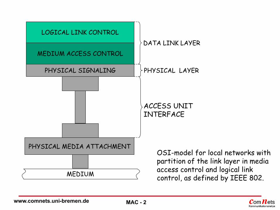
LOGICAL LINK CONTROL
MEDIUM ACCESS CONTROL
PHYSICAL SIGNALING
PHYSICAL MEDIA ATTACHMENT
MEDIUM
DATA LINK LAYER
PHYSICAL LAYER
ACCESS UNIT INTERFACE
OSI-model for local networks with partition of the link layer in media access control and logical link control, as defined by IEEE 802.

www.comnets.uni-bremen.de MAC - 3
Multiple Access Protocols (Vielfachzugriffsprotokolle)
MAC: Medium (Multiple) Access Control
Influence Medium (Übertragungsmedium)
Network Topology (Netztopologie)
Performance Aspects

www.comnets.uni-bremen.de MAC - 4
Multiple Access Protocols
centralized:
Polling
Aloha with collision resolution methods
Reservation Aloha
CDMA
Code Division Multiple Access
Carrier Sensing
FDMA
Frequency Division Multiple Access
Slotted Aloha
TDMA
Time Division Multiple Access
decentralized:
Token Passing
Register Insertion
Ring
DQDB
Pure Aloha
Reservation
Methods
Scheduling
Methods
Random Access
Methods

www.comnets.uni-bremen.de MAC - 5
Competitive Methods
Random Access Schemes (Zufallszugriff)
Every station with data to send can principally access the channel
Transmission successful, when only one station accesses the medium
Concurrent access of more than one station at the same time leads to errors

www.comnets.uni-bremen.de MAC - 6
Scheduling Methods (Zuteilungsverfahren)
Perfectly scheduled
Centralized: Polling:
a master station polls each station in turn
Decentralized: all stations are equal
(Token Passing, Register Insertion, DQDB)

www.comnets.uni-bremen.de MAC - 7
Reservation Methods (Reservierungsverfahren)
Examples: TDMA, FDMA, CDMA
Management of a channel by a central station
Channel with synchronous multiplexing techniques with subchannels
Assignment of one or more channels on request
Request in a fixed subchannel through random access or scheduling method
Combined Methods

www.comnets.uni-bremen.de MAC - 8
Network Topology
Polling: (usually) star topology
master in the center
Ring / Bus: pairs of fiber channels,
often separate rings or busses in both directions
(dual ring, dual bus)
Mobile Radio Networks
usually use random access methods for reservation
Reliability (Ausfallsicherheit) and Robustness: Polling ?
Random access methods ?
Critical: error in central station Critical: error in central station
Critical: high load Critical: high load

www.comnets.uni-bremen.de MAC - 9
Performance Evaluation of Methods
Offered Traffic (Verkehrsangebot)
Transmission Time (Übertragungszeit)
Throughput (Durchsatz)
Which methods are to be preferred for high and low traffic?
How does the offered traffic influence throughput and transmission time?
Random access methods lead to lower
transmission times for low or high traffic?
Reservation and Scheduling Strategies lead to
lower transmission times for low or high traffic? high high
low low

www.comnets.uni-bremen.de MAC - 10
Aloha Protocols
Development at the University of Hawaii end of the 60s for the transmission of packet data in a radio network between terminals and a central computer
Basic method of all random access methods
Easy to implement, no complex coordination
Unsuccessful transmissions are repeated
Robust against transmission errors
Used in mobile radio networks, e.g., GSM (Global System for Mobile Communication) or TETRA (Trans-European Trunked Radio, digitaler Bündelfunk) for reservation
Collisions

www.comnets.uni-bremen.de MAC - 11
Assumptions for the Evaluation of Collision Resolution Methods
(Kollisionsauflösungsverfahren) (1) m sending stations and exactly one receiver station One jointly used channel from all sending stations to the
receiver Channel close to error free Data packets generated in all stations with Poisson
distribution with rate m, all packets of equal length, X transmission time of a packet Immediate Transmission for Pure (Unslotted) Aloha Transmission in the next time slot for Slotted Aloha Transmission successful when only one sender
accesses the channel during the transmission Collisions for concurrent access Immediate feedback: sender knows immediately whether
or not the transmission was successful

www.comnets.uni-bremen.de MAC - 12

www.comnets.uni-bremen.de MAC - 13
Assumptions for the Evaluation of Collision Resolution Methods (2)
No loss: sender retransmits packet until the transmission is successful
Station is backlogged, as long as the transmission of a packet is repeated
No buffering assumption: stations in a backlogged state do not generate additional packets
Infinity assumption: the number m of stations are assumed to be infinite, i.e., m ∞
Probability for generating a packet
at a specific station in time T:
P{Generate a Packet in time T}=
(Poisson Distribution)
m
T
em
T

www.comnets.uni-bremen.de MAC - 14
Pure Aloha (unslotted)
Basic random access method
Station sends packet immediately after arrival
Packet is received successfully when no other station sends during the same time
Acknowledgement by receiver immediately after transmission
Collision: two or more stations sending during the same time, no acknowledgement
Sender sends packet again after a random time until packet is successfully transmitted (Acknowledgement)

www.comnets.uni-bremen.de MAC - 15
www.comnets.uni-bremen.de MAC - 16
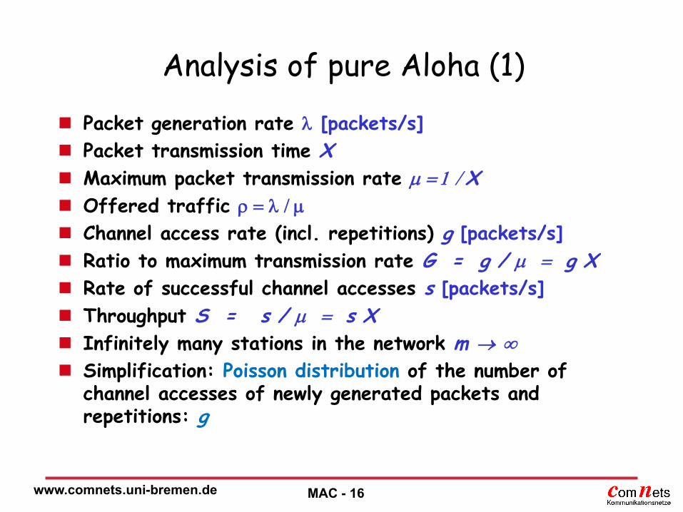
Analysis of pure Aloha (1)
Packet generation rate [packets/s]
Packet transmission time X
Maximum packet transmission rate X
Offered traffic
Channel access rate (incl. repetitions) g [packets/s]
Ratio to maximum transmission rate G = g / g X
Rate of successful channel accesses s [packets/s]
Throughput S = s / s X
Infinitely many stations in the network m
Simplification: Poisson distribution of the number of channel accesses of newly generated packets and repetitions: g

www.comnets.uni-bremen.de MAC - 17
www.comnets.uni-bremen.de MAC - 18
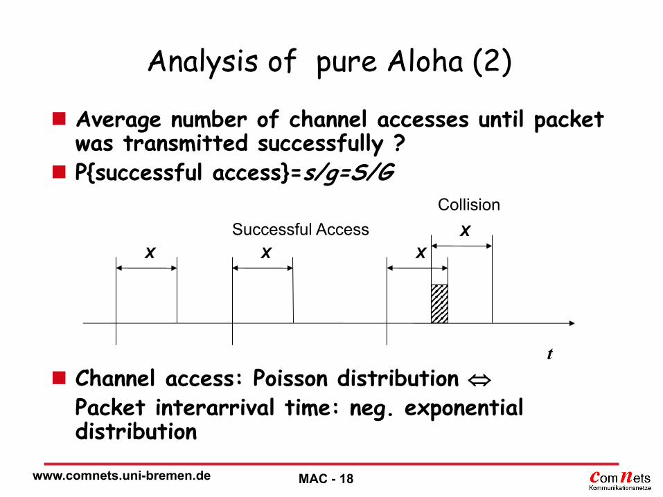
Analysis of pure Aloha (2)
Average number of channel accesses until packet was transmitted successfully ?
P{successful access}=s/g=S/G Channel access: Poisson distribution Packet interarrival time: neg. exponential
distribution
X X X
t
X Successful Access
Collision

www.comnets.uni-bremen.de MAC - 19
Formulas for pure Aloha
5.0for %4.18184.02
1
success
maxmax
2
2
Ge
S
GeS
eXTPXTPP
eedtgeXTP
G
G
afterbefore
GgX
X
gt

www.comnets.uni-bremen.de MAC - 20

www.comnets.uni-bremen.de MAC - 21
Throughput “Pure Aloha” protocol
1
Gstab
0
0.02
0.04
0.06
0.08
0.1
0.12
0.14
0.16
0.18
0.2
0 1 1.5 2 2.5 3 0.5
2e
Glab
S
G

www.comnets.uni-bremen.de MAC - 22
Slotted Aloha
Receiver defines pattern of time slots of length X for the channel access
Stations access the channel synchronously to the predefined slot pattern
Otherwise: see pure Aloha
Synchronization leads to complete overlay of packets sent in the same time slot
Maximum Throughput relative to Pure Aloha?
Maximum Throughput is doubled!

www.comnets.uni-bremen.de MAC - 23
www.comnets.uni-bremen.de MAC - 24
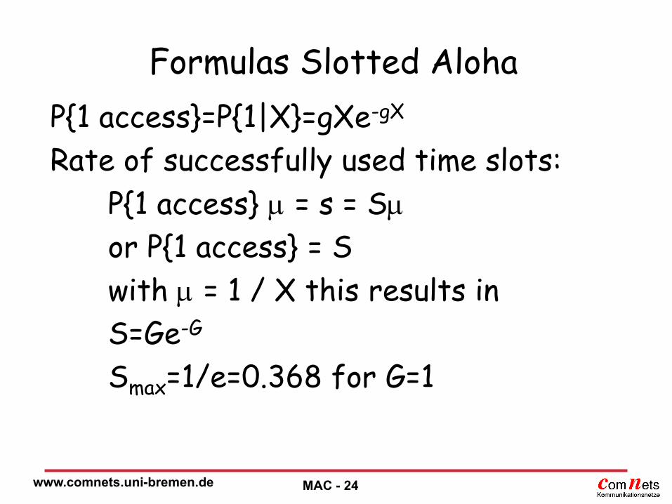
Formulas Slotted Aloha
P{1 access}=P{1|X}=gXe-gX
Rate of successfully used time slots:
P{1 access} = s = S
or P{1 access} = S
with = 1 / X this results in
S=Ge-G
Smax=1/e=0.368 for G=1

www.comnets.uni-bremen.de MAC - 25

www.comnets.uni-bremen.de MAC - 26
Throughput Slotted Aloha Protocol
0
0.05
0.1
0.15
0.2
0.25
0.3
0.35
0.4
0 0.5 1 1.5 2 2.5 3
1 e S
G

www.comnets.uni-bremen.de MAC - 27
Strategies for Collision Resolution
Binary Exponential Backoff Channel Access Probability qr
After j erroneous accesses qr is set to 2-j
Stabilization
Goal: Region of G=1 with high throughput S
or other more complex methods see Pseudo-Bayes-Algorithm [Bossert99]
Max. Throughput < 0.587
Tree Method: Throughput < 0.46
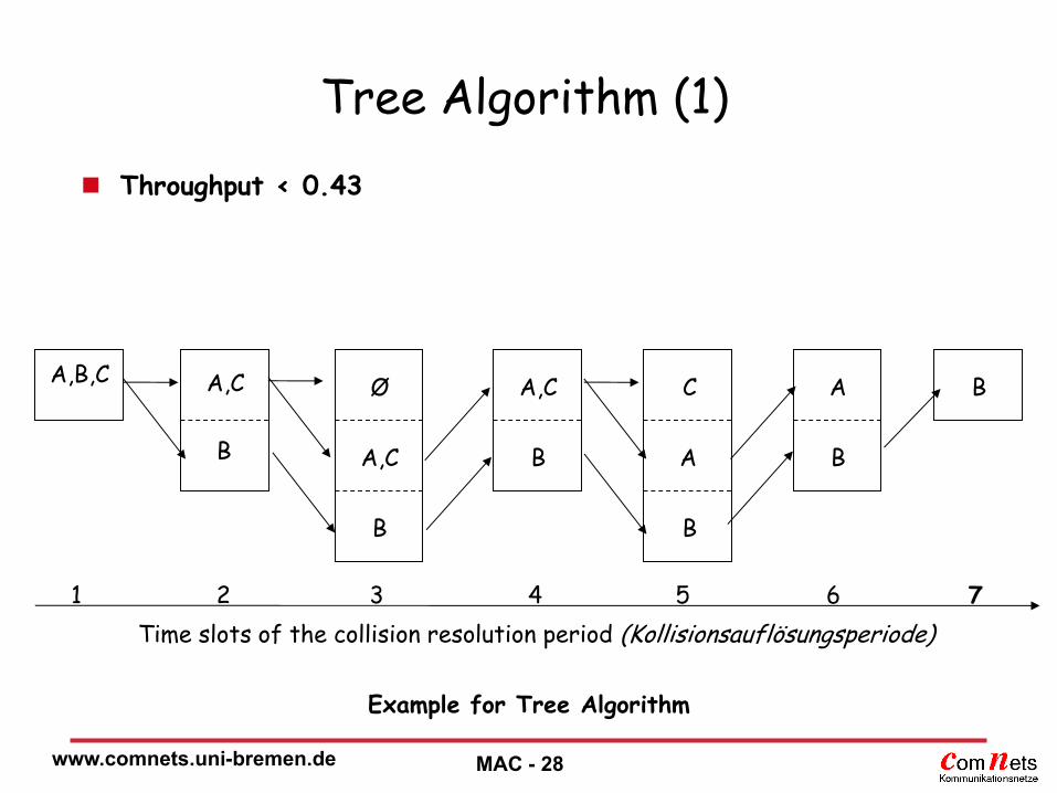
www.comnets.uni-bremen.de MAC - 28
Tree Algorithm (1)
Throughput < 0.43
1 2 4 3 5 6 7
Time slots of the collision resolution period (Kollisionsauflösungsperiode)
A,B,C
Example for Tree Algorithm
A,C
B
B
A,C
Ø
B
A,C
B
A B
B
A
C

www.comnets.uni-bremen.de MAC - 29
Tree Algorithm (2)
Throughput < 0.46
M2(5) M1(4)
M0(4) M1(3) M0(3)
M2(3) M1(2) M0(2)
M0(1)
M1(5) M0(5) M0(6)
M1(6) M0(7)
1 2 4 3 5 6 7
Time Slots of the Collision Resolution Period
Presentation of subsets as trees.

www.comnets.uni-bremen.de MAC - 30
FCFS-Algorithm (1)
Throughput < 0.4878
time slot time
two new packets
Example for the procedure of the FCFS-Algorithm

www.comnets.uni-bremen.de MAC - 31
FCFS-Algorithm (2)
No Collision
State diagram of the FCFS Algorithm
R0
L3 L1
R2 R1
L2 No Access No Access
Collision Collision
R3

www.comnets.uni-bremen.de MAC - 32
Carrier- Sensing- Methods
Prerequisite: all stations can “hear” each other Common Topology: Bus Collision Avoidance through so-called Carrier Sensing
(Abhören des Mediums auf Trägersignal) CSMA = Carrier Sense Multiple Access “Polite discussion” (höflich geführte Diskussion) Persistence: Persistent CSMA: channel is constantly monitored, access as soon as channel is free Non-persistent CSMA: monitor channel, if busy -> random time
delay, listen to channel, access as soon as channel is free p-persistent CSMA: Mixture, listen to channel until free,
access with probability p, random time delay, listen to channel

www.comnets.uni-bremen.de MAC - 33
End of transmission
Start of transmission
Station 1 Station 2
Time
Station 1 Station 2
Start of transmission
End of transmission
vulnerable period
= max. signal propagation delay between 2 stations L = mean packet length [bit] C = channel transmission rate [bit/s] X = mean packet transmission delay X = L / C Parameter = / X = C / L

www.comnets.uni-bremen.de MAC - 34
CSMA: Throughput
Non-persistent CSMA
m stations
States of the channel:
free, successful transmission, collision
k: number of stations ready to send a packet
Other assumptions: see Aloha Protocol

www.comnets.uni-bremen.de MAC - 35
CSMA: Throughput (1) CSMA throughput ( = 0,1)
0.1
0.15
0.2
0.25
0.3
0.35
0.4
0.45
0.5
0.55
0 2 4 6 8 10 12 14
G(k)
S(k)
G(k)stab G(k)lab
21
1max
S

www.comnets.uni-bremen.de MAC - 36
CSMA: Throughput (2) CSMA throughput for different
0
0.1
0.2
0.3
0.4
0.5
0.6
0.7
0.8
0.9
1
0 5 10 15 20 25 30
= 0,1
= 0,01
= 0,001
= 0,0001
G (k)
S (k)
www.comnets.uni-bremen.de MAC - 37
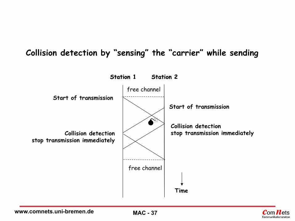
Collision detection by “sensing” the “carrier” while sending
Station 1 Station 2
Time
Start of transmission
Start of transmission
Station 1 Station 2
Collision detection stop transmission immediately Collision detection
stop transmission immediately
free channel
free channel
www.comnets.uni-bremen.de MAC - 38
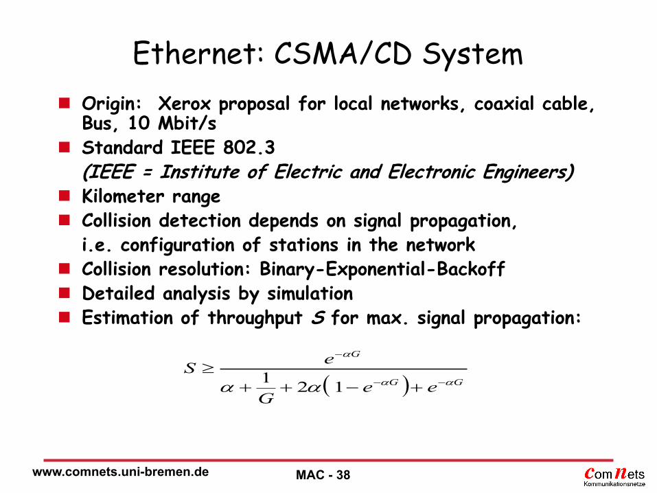
Ethernet: CSMA/CD System
Origin: Xerox proposal for local networks, coaxial cable, Bus, 10 Mbit/s
Standard IEEE 802.3 (IEEE = Institute of Electric and Electronic Engineers) Kilometer range Collision detection depends on signal propagation, i.e. configuration of stations in the network Collision resolution: Binary-Exponential-Backoff Detailed analysis by simulation Estimation of throughput S for max. signal propagation:
GG
G
eeG
eS
121

www.comnets.uni-bremen.de MAC - 39
CSMA / CA (Collision Avoidance)
Collision detection, e.g. in radio networks usually not possible, sent signal conceals external received signal
Collision avoidance strategy:
Sequence of access for all stations in the network
Segment time into time slots of duration
slightly larger than max. signal propagation
Fixed or Random assignment of slots to stations
Station is only allowed to access assigned time slot
Time pattern is interrupted, as soon as a station is in sending mode
Time slot is an implicit token
Example: IEEE 802.11b WLAN
(installation at University of Bremen / NW1)

www.comnets.uni-bremen.de MAC - 40
Polling
Central assignment of sending right Formerly mainframe access for terminals Mainframe as master Terminals are polled cyclically Simple implementation Disadvantage: overhead of polling idle terminals
results in considerable overhead for a large number of stations
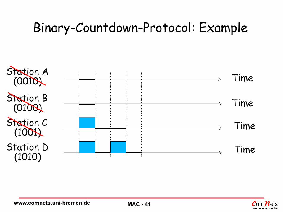
Improvement by so-called Binary-Countdown-Protocol o Stations are assigned network IDs o Stations broadcast their network IDs simultaneously o Stations with highest network ID bit = 1 wins o Repeat until station with highest network ID bit ready to send
remains o In each step the address space is divided by 2: k = log2 m o Fairness?
www.comnets.uni-bremen.de
Binary-Countdown-Protocol: Example
MAC - 41
Station A (0010)
Station B (0100)
Station C (1001)
Station D (1010)
Time
Time
Time
Time

www.comnets.uni-bremen.de MAC - 42
Token-Passing Methods
Examples:
Token-Bus IEEE 802.4
Token-Ring IEEE 802.5
FDDI (Fiber Distributed Data Interface)
General Token-Passing Characteristics:
Scheduling Method:
Station receives sending right through a so-called token
Transfer of the sending right by sending the short token to the next station
No Collisions
Limit of max. time until sending right is acquired is possible (e.g. by limiting time or number of packets), suitable for real time services, priorities
Router

www.comnets.uni-bremen.de MAC - 43
Token-Bus (IEEE 802.4) Token release after a max. of 10 ms
Logical Ring implemented on bus topology
Can handle hardware failures
Changes of the logical ring structure
Deleting stations: Controlled: Station informs predecessor
Uncontrolled, e.g. by error: after releasing a token, Station watches if successor releases token itself, otherwise a message is sent to all stations, successor (of successor) answers or logical ring is newly established.
Adding stations: Stations regularly ask new stations to send a notification.
Establishing new logical ring: if a station has not noticed any access to the bus over a sufficiently long period of time, the station defines itself as the first station and stations are added with the same procedure as above.
This standard has been withdrawn by the IEEE

www.comnets.uni-bremen.de MAC - 45
Token-Ring (IEEE 802.5)
Point-to-point connections of neighbouring stations
Unidirectional mode of operation
Data is passed on until it reaches the sender again
Stations that are switched off or damaged are bridged (switch in the interface)
Tokens are 3 bytes in length and consist of a start delimiter, an access control byte, and an end delimiter.
Lost token, duplicate token: Monitor Station (arbitrary but fixed station) generates
new token after max. token rotation time

www.comnets.uni-bremen.de MAC - 46
FDDI – Fiber Distributed Data Interface
ISO Standard ISO-9314 (ANSI)
Fiber with 100 Mbit/s
Copper cables can also be used (CDDI)
Range is up to 200 km
Logical topology is ring-based token network
Timed Token Protocol based on 802.4
FDDI network usually contains two rings
Primary ring
Secondary ring (for backup purpose)
Deployed as backbone network in 90s

www.comnets.uni-bremen.de MAC - 47
FDDI – Fiber Distributed Data Interface
Standard
High throughput
Not developed further
Only one data rate
More expensive than Fast Ethernet and Gigabit Ethernet

www.comnets.uni-bremen.de MAC - 50
DQDB (Distributed Queue Dual Bus)
IEEE 802.6 Standard (1991)
155 Mbit/s, Data and Voice
Scheduling Method
Decentralized organization, synchronized system, priorities
ATM-like cell structure with 48 byte payload
(ATM: Asynchronous Transfer Mode)
PLT (Payload Type) only 2 bit,
SPR=Segment Priority
MAN = Metropolitan Area Network
or HSLAN = High Speed Local Area Network
2 unidirectional busses, reverse direction of transmission, not limited in range/distance

www.comnets.uni-bremen.de MAC - 51
DQDB Topology
Cell Generator
Terminator Cell Generator
Terminator
....
Cells
Cells

www.comnets.uni-bremen.de MAC - 52
DQDB Cell Format
1 octet
ACF – Access Control Field
HEC – Header Error Control
Information Field 48 Octets
53 o
ctets
VCI – Virtual Channel Identifier 20 bit PLT SPR
Bit 1: Busy
Bit 2: Slot Type
Bit 3: PSR
Bit 4-5: RES
Bit 6: Req 2
Bit 7: Req 1
Bit 8: Req 0
www.comnets.uni-bremen.de MAC - 53
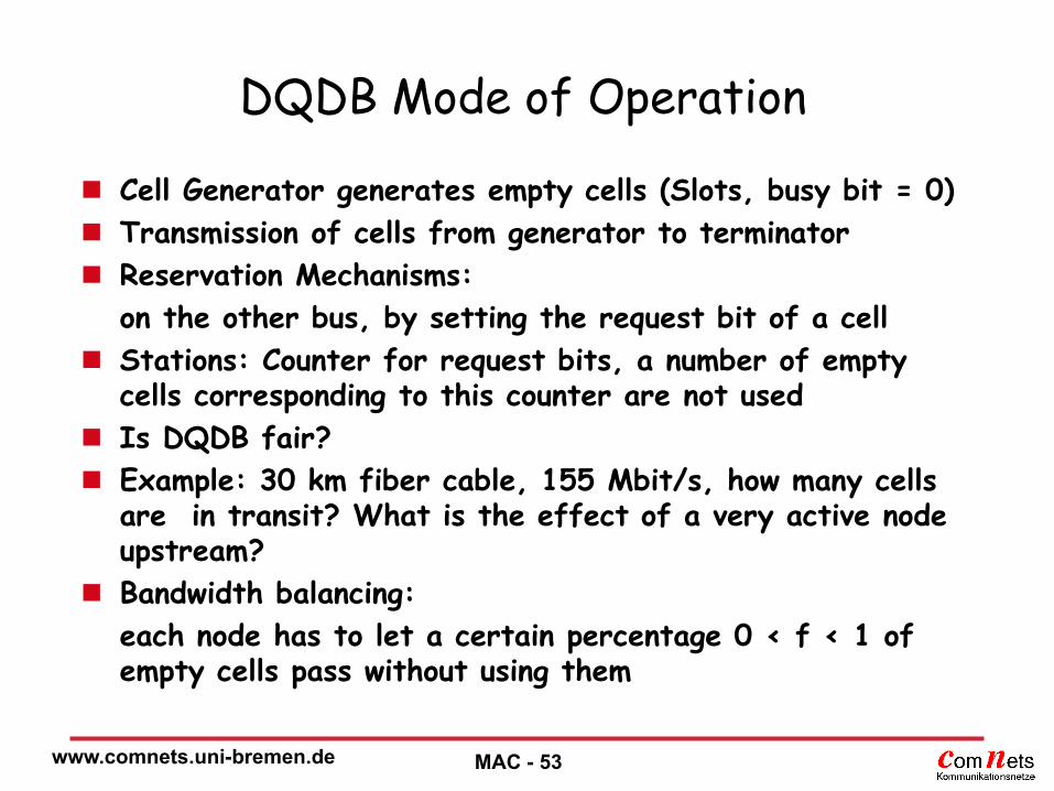
DQDB Mode of Operation
Cell Generator generates empty cells (Slots, busy bit = 0)
Transmission of cells from generator to terminator
Reservation Mechanisms:
on the other bus, by setting the request bit of a cell
Stations: Counter for request bits, a number of empty cells corresponding to this counter are not used
Is DQDB fair?
Example: 30 km fiber cable, 155 Mbit/s, how many cells are in transit? What is the effect of a very active node upstream?
Bandwidth balancing:
each node has to let a certain percentage 0 < f < 1 of empty cells pass without using them