
Data Framing - University of Auckland
34
COMPSCI 314 S1 C Data Comms - Basics 18-Mar-05 1 Data Framing • Most communication sends bit-serial data. How do we isolate the characters? Asynchronous Communication. • This is a very old technique, developed about 100 years ago for automatic teletypewriter equipment. • It is meant for slower speed communication, where the send and receive bit-timing clocks may differ by ±5%. 1. The communication line rests in state “1” – “sender is connected” 2. A character starts with a Start Bit, always “0”, typically lasting for 1.0 bit-times. 3. The data bits are sent in order, LSB first. 4. There may be a parity bit, to check transmission accuracy. 5. The character ends with a Stop Bit, always a “1”. This may be 1.0, 1.5, or 2.0 bits long.
Transcript of Data Framing - University of Auckland

COMPSCI 314 S1 C Data Comms - Basics 18-Mar-05 1
Data Framing
• Most communication sends bit-serial data. How do we isolate the characters?
Asynchronous Communication.• This is a very old technique, developed about 100 years ago for
automatic teletypewriter equipment.• It is meant for slower speed communication, where the send and
receive bit-timing clocks may differ by ±5%.1. The communication line rests in state “1” – “sender is connected”2. A character starts with a Start Bit, always “0”, typically lasting for
1.0 bit-times.3. The data bits are sent in order, LSB first.4. There may be a parity bit, to check transmission accuracy.5. The character ends with a Stop Bit, always a “1”. This may be
1.0, 1.5, or 2.0 bits long.

COMPSCI 314 S1 C Data Comms - Basics 18-Mar-05 2
A Simple Asynchronous Block-mode protocol
• The connection was like Ethernet (but much slower)• Each station had an address, a single ASCII character• The CPU cycled round all stations:
– POL (do you have a message?) or – SEL (can you receive a message?)
• Characters were 7-bit ASCII, with even parity.• Messages had an even parity longitudinal parity (BCC –
Block Check Character), including all characters from address to ETX.
This protocol was used on Burroughs terminals, to about 38,400 bps, during the 1970’s.
Terminals (multi-dropped on a single line)
Central Processor (with data communications processor)

COMPSCI 314 S1 C Data Comms - Basics 18-Mar-05 3
ASCII Control characters
Can you receive a message?qsel0x71
Is there a message to send?ppol0x70
Error in received message.Negative ACKNAK0x15
Message received correctly.AcknowledgeACK0x06
Terminal must respond.EnquireENQ0x05
No more data to send.End of TransmissionEOT0x04
End of TextETX0x03
Start of TextSTX0x02
Introduces message headerStart of HeaderSOH0x01
The protocol used the following ASCII control (non-data) characters
The final Block Check Character (BCC) is data-dependent and can be any value.
ETX BCCdataSTXheaderSOH

COMPSCI 314 S1 C Data Comms - Basics 18-Mar-05 4
Burroughs TD800 Poll SequenceCentral Processor
EOTAddressPOL (‘p’)ENQ
Poll Sequence:Is there a message to send?
Terminal
Error
NAK
No message
EOT
Ready To Send
SOHAddressSTXDataETXBCC
EOT
Processor times out(say 1 second)
Received OK
ACKUp to 10 retries
Invalid
(Ignore)
EOT - usually proceed to next poll (or select)

COMPSCI 314 S1 C Data Comms - Basics 18-Mar-05 5
Burroughs TD800 Select SequenceCentral Processor
EOTAddressPOL (‘q’)ENQ
Select Sequence:OK to send?
Terminal
Error
NAK
Not ready to receive
Ready to receive
Processor times out(say 1 second)
Received OK
ACK
Invalid
(Ignore) NAK ACK
EOTSOHAddressSTXDataETXBCC
Continue to Select (if message to send), or to Poll
Up to 10 retries

COMPSCI 314 S1 C Data Comms - Basics 18-Mar-05 6
Example of Parity Calculation• The character parity (most-sig bit) is set to give an even number of
bits in the character.‘a’ = 0x61 = 110 00012 has three 1-bits and becomes 1110 0001
• The message parity is the Exclusive-OR (⊕ ) of the 7-bit message character codes:
the BCC of the first 4 octets is 01 ⊕ 31 ⊕ 02 ⊕ 44 = 76• Data message is Data Example, sent to address 1.• Character and message (longitudinal) parity are both even
• The receiver checks both character parity and overall message parity and requests retransmission if either fails.
• The receiver also checks for the correct structure, eg SOH addr STX and ignores bad messages
• Character parity, including BCC, is added on transmission.
81 B1 82 44 E1 74 E1 A0 C5 78 E1 ED F0 6C 65 03 69Hex with parity
01 31 02 44 61 74 61 20 45 78 61 6D 70 6C 65 03 69Hex value
SOH 1 STX D a t a E x a m p l e ETX BCCCharacter

COMPSCI 314 S1 C Data Comms - Basics 18-Mar-05 7
• Well-defined message formats, with extensive checking• Well-defined question-response sequence, such as
Do you have a message? (poll)Yes, and here it is (the data)
I have it correctly (ACK)I have no more messages (EOT)
• Retry in case of error, up to some agreed limit (say 10 times).
• If errors persist, report to higher layers of software.• Control station can “timeout”, so it can recover if nothing
is received.– A timeout is an essential part of any useful protocol.
• This is a “stop and wait” protocol – it sends a message and waits for a reply.
This example shows many features of data communications protocols:

COMPSCI 314 S1 C Data Comms - Basics 18-Mar-05 8
Synchronous Communication1. Introduced for computers and semi-intelligent terminals
which send blocks of data.2. Used with modems which convey bit-timing and tell the
receiver when to accept a bit — the receiver does not have to infer bits.
3. All data is sent as blocks or frames, each preceded by two or three special SYN (Synchronisation) codes.ASCII 0x16 01101000 (lsb first)EBCDIC 0x32 01001100 (lsb first)
4. Receiver searches bit by bit for the pattern SYN SYN (in binary ASCII: 0001011000010110).
5. It then delivers one character per 8 bit-times (seldom use character parity).

COMPSCI 314 S1 C Data Comms - Basics 18-Mar-05 9
Binary Synchronous Control (BSC) protocol
1. Used by IBM at about the same time as Burroughs TD800 protocol, but for similar purposes.
2. Intended for 8-bit EBCDIC, not 7-bit ASCII: no character parity, and need a better message parity. (Use 16-bit cyclic redundancy check.)
3. Can be used for true binary data, with “byte stuffing”.4. The simplest message format is for normal text
SYN SYN SOH header STX data ETX BCC
5. This is just like the TD800 protocol, except that it uses EBCDIC and has two leading SYN characters (but TD800 could also use synchronous ASCII).
6. A very long message may be broken into blocks, each ending with ETB (End of Transmission Block), and last block ending with ETX.

COMPSCI 314 S1 C Data Comms - Basics 18-Mar-05 10
Character ‘E’ 0x45’, 01000101
• Character is “synchronised” from leading edge of Start Bit• Hardware device is UART
– “Universal Asynchronous Receiver Transmitter”
• UART can select parameters:– Data Bits: 5, 6, 7, or 8 – Parity: Odd, Even, 0, 1, or none– Stop Bits: 1.0, (rarely1.5, or 2.0)– Bit-time: e.g. for 9600 bits/second, 1 bit-time is 1/9600 second.
1
01 2 3 4 5 6 7 8
Data BitsStartBit
StopBit
ParityBit
StartBit
1 2 3 4
Bit timing clocks
First character (E) Next character

COMPSCI 314 S1 C Data Comms - Basics 18-Mar-05 11
UART Operation1. A UART is usually given a clock at 16× the desired bit
rate, e.g. clock frequency may be 16 × 9600 bps.2. The clock is “counted down” by 16 times for transmission3. For reception, look for a change 1→0; this is the start of
the Start Bit4. Then count 8 clocks; this should be the middle of the
Start Bit5. Then count off successive 16 clocks for each data bit.6. Read the parity bit; is it correct? (if not then Parity Error)7. Read the Stop Bit; is it 1? (if not then Framing Error)8. “Idle” until the next Start Bit (8 ≤ delay < ∞ clocks)

COMPSCI 314 S1 C Data Comms - Basics 18-Mar-05 12
Asynchronous characteristics and usage
1. Originally used for electromechanical equipment, hence1.5 stop bits (with 5-bit data, 75 bps), 2 stop bits (ASCII 7-bit+parity, 110 bps)Now use only 1 stop bit with modern electronic communication
2. Asynchronous communication is relatively inefficient, at least 25% overhead from start/stop bits
3. Used mainly where there is no shared clock from sender to receiver, OR
4. with very short messages, perhaps just 1 character.5. Data is now either 7 or 8 bits, and parity may be present
or absent.

COMPSCI 314 S1 C Data Comms - Basics 18-Mar-05 13
Bisync Transparent mode• What happens if the data might contain an ETX
character?– Text from a terminal certainly will not have an ETX, but we might
want to send pure binary data.• The answer is to use “byte stuffing” = inserting DLE
(Data Link Escape) codes in appropriate places.• Transparent mode is signalled by a DLE STX in place of
the beginning STX and a message is ended by the pair DLE ETX.SYN SYN SOH header DLE STX data DLE ETX BCC
• What if the message contains a genuine DLE ETX?– Replace any data DLE by DLE DLE and treat the following
character as data.• DLE ETX is sent as DLE DLE ETX.
• What if there’s a genuine DLE DLE?– Send DLE DLE DLE DLE.

COMPSCI 314 S1 C Data Comms - Basics 18-Mar-05 14
The BSC protocol• The BSC protocol is similar in principle to the
TD800 protocol, but differs of course in detail.• Both are stop and wait protocols.• Both have a controlling, or Primary, station with
one or more Secondary stations.– The Primary station always initiates an operation.– A Secondary station always responds.
• BSC and TD800 are now obsolete, and were replaced by the HDLC (or SDLC) protocols to be described.– HDLC/SDLC is nearly obsolete, too!– The concepts are still important. Some are reflected
in current protocols, and some may be “resurrected” in your lifetime.

COMPSCI 314 S1 C Data Comms - Basics 18-Mar-05 15
Synchronous Data Link Control (SDLC), orHigh-level Data Link Control (HDLC)
• These were introduced in conjunction with the ISO Open System Interconnection (OSI) model, which included X.25.
• Although HDLC itself is little used now, many of its details have carried over into present protocols.
• The HDLC frame format is
• The address and control sizes are agreed at set-up time• Apart from the flags, there is little framing or other
overhead.
FlagFCSData
(N chars)
ControlAddressFlagDescription
Width (bits) 8 816 or 328 × N8 or 168 or 16

COMPSCI 314 S1 C Data Comms - Basics 18-Mar-05 16
Bit Stuffing• The Flags which surround an HDLC frame are always the eight-bit
pattern 01111110.– Six consecutive ‘1’s, surrounded by 0’s.
• Arbitrary (binary) data is handled by “bit stuffing” with three rules:
1. On transmission, always force a ‘0’ after five consecutive 1’s.– “Stuff” in an extra ‘0’ bit after the pattern 11111.
2. On reception, ignore any ‘0’ bit which is preceded by five 1’s. – In other words 111110 → 11111.
3. Flags are inserted after bit-stuffing on transmission, and detected before “un-stuffing” on reception.
• On random data, we can expect the pattern …011111… to occur about once every 26 = 64 bits.– On average, one extra bit for every 64 data bits, or about 1.5%
expansion.• Note that a complete HDLC frame (including flags!) can be
tunnelled within another HDLC frame.

COMPSCI 314 S1 C Data Comms - Basics 18-Mar-05 17
HDLC Control fields• The control field is usually 8 bits, in one of three formats• An Information Frame starts with a 0 (in the LSB position!) and
conveys normal data. The fields will be discussed later.
• A Supervisory Frame is used for acknowledgements, including not-ready indications.
• An Unnumbered Frame is used for various control functions.
# of bits:
N(R)P/FN(S)0
3131
M
2
MP/F11
3111
S
2
N(R)P/F01
3111

COMPSCI 314 S1 C Data Comms - Basics 18-Mar-05 18
HDLC Control Fields• P/F (Poll/Final).
– If sent by a Primary station, it is a “poll” bit and demands a response.– If sent by the Secondary, it is a “final” bit signalling the last frame in a
sequence of frames• N(S) and N(R) are send and receive sequence numbers, used in
flow control.• S is a function field:
RR Receive Ready ready to receive frame N(R)REJ Reject reject frame N(R); send it and all followingRNR Receive Not Ready received frame N(R), but send no moreSREJ Selective Reject resend only frame N(R)
• M is another function field, mostly used for link control, connection and disconnection.
• The final CRC (Cyclic Redundancy Check) is a 16-bit checksum (possibly 32-bit) as discussed later.

COMPSCI 314 S1 C Data Comms - Basics 18-Mar-05 19
HDLC Configurations• A Primary station can send commands.• A Secondary station can send responses.
PrimaryStation
SecondaryStation
commands
responses
Point-to-point link
PrimaryStation
SecondaryStation
commands
responses
Multipoint link
PrimaryStation
SecondaryStation
commands and responses
responses and commands
Point-to-point link between combined stations
SecondaryStation
SecondaryStation

COMPSCI 314 S1 C Data Comms - Basics 18-Mar-05 20
HDLC communication modes1. In Normal Response Mode (NRM) the primary stations
controls the operation, just as in the earlier protocols.2. Asynchronous Response Mode (ARM) is like NRM, but
allows a secondary to send data or control information without explicit permission, but it cannot send commands. Both NRM and ARM are intended to connect dumb terminals to a computer.
3. Asynchronous balanced mode (ABM) allows both stations to send both commands and responses. It is the usual method between computers.
4. All modes have an extended mode, with seven-bit sequence numbers.
5. There are unnumbered commands to set these modes:SARM SARME Set Asynchronous Response Mode (E)SNRM SNRME Set Normal Response Mode (E)SABM SABME Set Balanced Response Mode (E)

COMPSCI 314 S1 C Data Comms - Basics 18-Mar-05 21
Other important Commands and Responses
RSET Reset Reset N(R) and N(S)
SIM Set initialization mode Reset data link control functions DISC Disconnect Disconnect, or break, connection
DM Disconnect Mode Station is disconnected
CDMR Command Reject ACK receipt of unacceptable command
UA Unnumbered acknowledge ACK receipt of acceptable command
FRMR Frame Reject NAK: received frame is damagedor out of order.
UI Unnumbered Information ACK, plus information requested;
UI may be sent from Primary
in NRM (i.e. as a Command).

COMPSCI 314 S1 C Data Comms - Basics 18-Mar-05 22
Link controlTwo examples of link connection and disconnection
Normal Response Mode, or Multidrop Asynchronous Balanced Mode
Primary(A)
Secondary(B)
CombinedP/S (A)
CombinedP/S (B)
V(S)=0
V(R)=0
Primarydisconnected
V(R)=0V(S)=0
Secondarydisconnected
SNRM(B,P=1)
UA(B,F=1)
Data Transfer
DISC(B,P=1)
UA(B,F=1)
V(S)=0
V(R)=0
V(R)=0V(S)=0
Secondarydisconnected
SABM(B,P=1)
UA(B,F=1)
Data Transfer
UA(A,F=1)
DISC(A,P=1) Primarydisconnected
Primary andsecondary
disconnected

COMPSCI 314 S1 C Data Comms - Basics 18-Mar-05 23
Flow Control
Flow control allows a receiving station to control transmissions so that it (the receiver) is not overwhelmed. There are several types of flow control —
1. Stop-Go, or ARQ, or XON/XOFF.• The receiver completely starts or completely stops transmission,
often on a single message basis.2. Buffer Control (Window control).
• The receiver notifies the sender of how many buffers are available to receive data.
• Increasing the number of buffers often allows higher user data rates (if link latency is important).
• Decreasing the number of buffers reduces the traffic; zero buffers implies traffic stopped.
3. Rate Control.• Allow packets to be sent at some maximum rate — good for for
some long-delay networks. Not treated here.

COMPSCI 314 S1 C Data Comms - Basics 18-Mar-05 24
Sliding Window flow control• Stop-and-Wait protocols (ARQ protocols) may give slow data
transfers because every message involves several send-wait-receive-wait sequences.– On long distance links, the waits can be large and may greatly reduce
the useful network speed.– But waits may be necessary in a half-duplex connection.
• With a full-duplex connection both stations can send and receive simultaneously and we may send several messages while waiting for the first to be acknowledged, leading to a sliding windowprotocol.
• With a sliding window protocol every message has a sequence number, incremented for successive messages, so that the transmitter and receiver can agree on which messages have been sent and which received.
• Acknowledgements are, if possible, “piggy-backed” onto reverse traffic (using the N(R) field of the message). Otherwise use RR response.

COMPSCI 314 S1 C Data Comms - Basics 18-Mar-05 25
• Start with messages 0–7 sent, and messages 0–2 acknowledged.• If message 3 is acknowledged, the window can advance and allow
message 8 to be sent.Message 0Message 1Message 2Message 3Message 4Message 5Message 6Message 7Message 8Message 9Message 10Message 11Message 12Message 13Message 14
These (later)messages arestill to be sent.
These (earlier) messages have been sent and received.
These messages are outstanding, but the windowhas moved.
These (later)messages arestill to be sent.
These (earlier)messages have beensent and received.
(Earlier) message 7 sent;message 2 received.
(Later) message 9 sent;message 4 received.
These messagesare outstanding:the “window”.
Window size = 5messages
• After message 4 has been acknowledged, the window can advance and allow another two messages to be sent.

COMPSCI 314 S1 C Data Comms - Basics 18-Mar-05 26
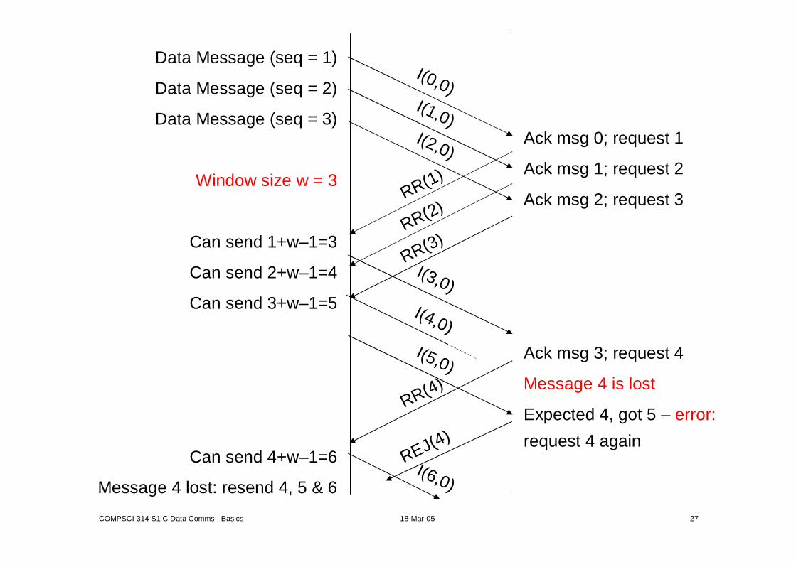
• HDLC usually works with a 3-bit sequence number, or frame numbers 0–7, which increments modulo-8.
• The sender has a variable V(S), the number for the next frame to be sent.
• The receiver has a variable V(R), for the next frame which it expects.
The HDLC sequence numbers can be increased to 7 bits (window size = 127) to handle connections with long delays, such as satellite links.
NOTE : The end-nodes maintain variables V(S) and V(R); the values of these variables appear as the numbers N(S) and N(R) in the messages.
COMPSCI 314 S1 C Data Comms - Basics 18-Mar-05 27
Data Message (seq = 1)
Data Message (seq = 2)
Data Message (seq = 3)
Window size w = 3
Can send 1+w–1=3
Can send 2+w–1=4
Can send 3+w–1=5
Can send 4+w–1=6
Message 4 lost: resend 4, 5 & 6
Ack msg 0; request 1
Ack msg 1; request 2
Ack msg 2; request 3
Ack msg 3; request 4
Message 4 is lost
Expected 4, got 5 – error:
request 4 again
RR(1)
RR(2)
RR(3)
RR(4)
REJ(4)
I(0,0)I(1,0)I(2,0)
I(6,0)
I(3,0)
I(5,0)
I(4,0)

COMPSCI 314 S1 C Data Comms - Basics 18-Mar-05 28
Two retransmission disciplines1. Go-back-N. If a message is lost, resend that message
and all later ones.– This is simplest, if errors are rare and with small window sizes.– The receiver discards all messages, until the sequence is
reestablished.– It may be necessary to repeat a whole “window-size” of
messages.– In HDLC/X.25, go-back-N is signalled by a REJ response
frame.2. Selective repeat repeats only missing or faulty
messages. It is best if there is a large link latency and therefore a large window size.– The receiver needs more complex memory management to
reassemble messages in the right order (and they may have differing sizes).
– In HDLC/X.25, selective repeat is signalled by a SREJ response frame. In the above example frames 5 and 6 will have been sent and the repeated frame 4 could be acknowledged by RR(7), acknowledging all frames up to 6.

COMPSCI 314 S1 C Data Comms - Basics 18-Mar-05 29
Transmission times and link performance• The link “performance” almost always means
“How many correct bytes/octets can be transferred per second”?(Sometimes data loss rate, delay, or delay variation may be important)
• This means working out how many bytes of user data are transferred in a typical exchange, and how long that exchange takes.
• Recommend working this out from first principles in each case, rather than learning difficult formulæ.
• Remember that anything that happens takes time; calculate these times and add them up.
• If you have a 1 Mb/s link between Auckland and Wellington, but you are using a 14.4 kbps modem to connect to the Auckland end, thenthe speed is 14.4 kbps.
• If you have a heavily loaded network which can transfer at 10 kbps, then upgrading a 14.4 kbps modem to 56 kbps will have little effect.

COMPSCI 314 S1 C Data Comms - Basics 18-Mar-05 30
• Things to consider are –1. Frame overheads. If a frame has an overhead (header,
trailer, etc) of 20 octets, 100 bytes of user data needs a 120 byte frame and this 120 bytes must be used in working out times, but still 100 for data.
2. Acknowledgement overheads. The total length of the acknowledgement frame (RR or piggy-backed) must be added to the length of the data frame in calculating time.
3. Link latency. Information travels at 200,000 km/s (cable) or 300,000 km/s (radio) whether we like it or not. This transmission delay or latency must be included, especially for stop-and-wait protocols.
4. Turnaround delays. Many systems take time to finish transmitting, start receiving, and stabilise to deliver a reliable signal. This delay can be significant in the older stop-and-wait protocols with frequent line “reversals”.

COMPSCI 314 S1 C Data Comms - Basics 18-Mar-05 31
Example• Calculate the user data rate for a CPU sending 250-character blocks to a
terminal using the TD800 protocol, under the following assumptions:– Aynchronous transmission at 9600 bps: 8 data, 1 start, 1 stop bit– Address = 1 character– The line turnaround time is 5 ms– Distance from CPU to terminal is 1,000 km– Include the time required to run the “select” sub-protocol once per block.
Time (in ms)Select sequence (4 chars):
((4 char) × (10 b/char) / (9600 bps)) × (1000 ms/s) 4Latency to terminal: (1,000 km) / (200 km/ms) 5Turnaround, ACK reply (1 char) 6Latency to CPU + turnaround 10
250 B Message + 5 B overhead:((255 char) × (10 b/char) / (9600 bps)) × (1000 ms/s) 266
Latency to terminal 5Turnaround, ACK reply, latency to CPU, turnaround 16
Total time for 250 bytes of data 312
⇒ 312 ms to send 250B, so data rate is 2 kb / 312 ms = 6.4 kbps

COMPSCI 314 S1 C Data Comms - Basics 18-Mar-05 32
• It is instructive to repeat the exercise, but with a message of 2,000 characters, instead of the previous 250 characters.
Select sequence (4 chars):((4 char) × (10 b/char) / (9600 bps)) × (1000 ms/s) 4 msLatency to terminal: (1,000 km) / (200 km/ms) 5 msTurnaround, ACK, Latency to CPU, turnaround 26 ms
2000 B Message + 5 B overhead:((2005 char) × (10 b/char) / (9600 bps)) × (1000 ms/s) 2089 msLatency to terminal 5 msTurnaround, ACK reply, latency to CPU, turnaround 16 ms
Total time for 2000 B of data 2135 ms
⇒ 2.135 s to send 2000 B, so data rate is 16 kb / 2.135 s = 7.5 kbps
• The effective data rate is now very close to the maximum possible with asynchronous characters, or 9600*8/10 = 7680 bps.
• The larger message blocks have almost eliminated the effect of the signal and protocol overheads.
• Total time on “overhead”: 36 ms. Total time on user data: 2089 ms.

COMPSCI 314 S1 C Data Comms - Basics 18-Mar-05 33
Sliding windows performance• With full-duplex modems we eliminate the turnaround delays, and
with overlapped protocols, much of the effect of latency.• But the link must be “filled” with data, so the transmitter never waits.• Assume a satellite link:
altitude = 36,000 km; 1-way latency = 72,000 km = 0.24 s; round-trip latency: say 0.5 s
• As it takes 0.5 s to get an acknowledgement to a packet, we need a window with 0.5 s of data.At 9600 bps, 4800 bits = 4800/(128*8) = 4.69 pkts.
63,000631,000,0001,000
4,000450,0001,000
3,2002550,000128
64059600128
Bytes to buffer
Packets to buffer
Data rate, bps
Packet size, bytes

COMPSCI 314 S1 C Data Comms - Basics 18-Mar-05 34
• The first two lines correspond to X.25 (b1910) communication via satellite. A window size of 7 can handle 9,600 bps, but no more; hence there is a 7-bit sequence number option for a window of 127 packets.
• For a more modern example: consider – a trans-Pacific link (10,000 km each way),– sending 53-octet “cells” (for ATM transmission),– at 150 Mbps or greater.– The round-trip latency (20,000 km at 200,000 km/s) is 100 ms.
• As before, how many packets “fill” the round-trip link before we get a reply?
OC-192
OC-48
OC-12
OC-3
124.4162,437,4729.9532853
31.104586,8682.4883253
7.776146,7170.6220853
1.94436,6800.1555253
MBytes to buffer
Packets to buffer
Data rate, Gbps
Packet size, bytes