Data Encapsulation - LearnTech Training · o OSI Address Resolution Protocol ... (Open System...
21
DATA ENCAPSULATION Data Encapsulation - 101 This book will help you understand Data Encapsulation which is related to your Cisco CCENT/CCNA Certification studies. Author | Keith Gebhardt
Transcript of Data Encapsulation - LearnTech Training · o OSI Address Resolution Protocol ... (Open System...
DATA
ENCAPSULATION
Data Encapsulation - 101 This book will help you understand Data Encapsulation which is related to your Cisco
CCENT/CCNA Certification studies.
Author | Keith Gebhardt

DATA ENCAPSULATION | KEITH GEBHARDT 1
Visit us on
LearnTech Training - YouTube
Subscribe for new FREE
Lectures, Labs, and Promotion Offers for Udemy Courses!
This eBook is a companion for Data Encapsulation 101 course on udemy.com
All images and text in this document are copyright.
© Keith Gebhardt, 2017

DATA ENCAPSULATION | KEITH GEBHARDT 2
About this Course Have you ever heard anyone discussing how information is being communicated through
networks, and then all of the sudden feel completely lost in all of the tech lingo they are using?
Well, in this eBook you can expect to learn everything you need to know about the transmission
process of our data when it is sent across our networks, and all of the tech lingo that is usually
used to reference this process.
The process of sending our data through our networks is made possible by what’s called Data
Encapsulation. Now, before you can start to understand this important topic, you need to have
a decent understanding of the Networking Architecture Models, and some simple protocols we
use today. You will also want to be familiar with Broadcast and Collision Domains, and Network
hardware such as switches and routers.
This course will primarily be focused on teaching you everything you need to know about Data
Encapsulation, but we will go over the previously mentioned topics briefly just to familiarize
yourself with them, and see how everything fits into place. This course is especially useful for
any of you out there seeking a career position as a Network Administrator, Engineer, or even
Security analyst as it is crucial to understand how our data is being sent across the network and
how to monitor it for threats.
In this course, you will learn:
Introduction to Network Architecture Models
o TCP/IP
o OSI
Address Resolution Protocol
Introduction to Transport Layer Protocols
o TCP
o UDP
Introduction to Application Layer Protocols
o HTTP
o DNS
Introduction to Network Hardware
o Switches
o Routers
Introduction to Collison & Broadcast Domains
Data Encapsulation
o Segment
o Packet
o Frame

DATA ENCAPSULATION | KEITH GEBHARDT 3
Course Requirements Network Fundamentals
Cisco Packet Tracer
Wireshark
Notebook
Desire to Learn
Students should have a basic understanding of network fundamentals before taking this course.
______________________________________________________________________________
My “Cisco Networking Introduction” Course is available. Use PROMO CODE: EBOOK_DATACAP
to take the course for only $15! Normally $50.
LINK: https://www.udemy.com/cisco-networking-
introduction/?couponCode=EBOOK_DATACAP
______________________________________________________________________________
We will be using Cisco’s Virtual Network Simulator application called Packet Tracer which is
available on www.netacad.com. You can create a free account and then navigate to Packet
Tracer and *download the version suitable for your operating system.* We will use Packet
Tracer to build a couple of labs so you can familiarize yourself with how the information is being
communicated through our network.
We will also use a program used for Packet Sniffing called Wireshark just to show some
examples and get you familiar with it. This is not a Wireshark course so we will not cover it in-
depth, but I strongly encourage you to download it and become familiar with it as you move
forward in your studies. Wireshark can be downloaded for free at www.wireshark.org
I strongly encourage you to have a notebook to physically take notes, although I have this little
eBook typed up for you, physically writing down the information, listening, and watching me
explain it will ultimately help you retain the information that much better.
Last but, not least – You need to have a desire to learn! I say this with all my courses and with
all of my students simply for the fact that if you are not interested in learning this material, it
will become that much more difficult for you to retain the information and benefit from it. So,
enjoy the material, learn the material, and love the material and you will be Data Encapsulation
pros before you know it!
*NOTE* Cisco Packet Tracer is not available for MAC. You will need to install virtual box or VMware Fusion, and
boot Linux Ubuntu to install Packet Tracer.

DATA ENCAPSULATION | KEITH GEBHARDT 4
Chapter 1 To understand the Data Encapsulation process, we need to get you reacquainted with some of
the important basic networking topics first. We will start off by discussing the Network
Architecture Models.
Network Architectures
Network Architecture Models are essentially stacked layers which provide the devices on our
networks with a blueprint, or set of instructions for communicating our data across the network
successfully. Each layer in the models have a specific job to perform for our networks to
communicate, and they use specific protocols and standards related to each individual layer to
make that communication possible.
These models are what we call ‘known standards’ and we do not concern ourselves with them
as far as programming or a configuration standpoint. We don’t touch them. Our computers and
network devices are running specific applications with programming that already knows of
these rules and instructions. All’s we are concerned with is what each layer does, so we can
understand which devices, protocols, and standards are being used at any given point during
the communication of data through the networks.
There are two types of network architecture models as seen in Figure 1.1. We have the TCP/IP
Model and the OSI Model.
Figure 1.1 – Network Architecture Comparison

DATA ENCAPSULATION | KEITH GEBHARDT 5
When we discuss either of the network models, we always talk about them from the
application layer, working our way down, when discussing data encapsulation.
Two terms you should be familiar with are:
Same-Layer Interaction – Two computers use a protocols to communicate with the same layer
on another computer.
For example: TCP making a connection, and checking for packet loss – it will communicate to
the other PC at the same layer requesting that packet to be sent again.
Adjacent-Layer Interaction – On a single computer, one layer provides a service to a higher
layer, that higher layer requests that the next lower layer perform the needed functions.
For example: HTTP is an Application Layer Protocol, it needs the Transport Layer and its services
to perform – It needs to use TCP to establish a connection.
OSI (Open System Interconnection)
The OSI Network Architecture Model is the older of
the two models. Although it is the older model, we
still use the OSI layers to reference our networks in
today’s environments. It’s comprised of 7 layers –
Application, Presentation, Session, Transport,
Network, Data Link, and Physical. We will not go over
each of the seven layers in this course, however it is
imperative you learn each of the 7 layers for your
CCENT/CCNA Exam.
The layers you need to know to understand data
encapsulation for this course are:
Layer 7 (Application) – HTTP, DNS | Hosts/Clients
Layer 4 (Transport) – TCP, UDP | Hosts/Clients
Layer 3 (Network) – IP [IP Address] | Routers
Layer 2 (Data Link) – Ethernet [Mac Address] | Switch
Layer 1 (Physical) – NICs, Cabling, Hubs
When discussing data encapsulation for the OSI model, we use PDU’s to explain the process.
PDU’s are Protocol Data Units and represent each layer by - L number X PDU.
For example: Layer 4 would be L4PDU.
Figure 1.2 – OSI Model

DATA ENCAPSULATION | KEITH GEBHARDT 6
TCP/IP Model
The TCP/IP Model is the model that we currently use today. Although it is the model we use
today, its important to know that there are two versions of the TCP/IP Model. You have the old
model which was only comprised of 4 layers, and you have the new model which is comprised of
5 layers. When we discuss the TCP/IP model today, we are going to be referencing the newer
model with the 5 layers. Looking back at Figure 1.1, you can see that all 3 models are very similar.
There are only mild differences between the layers, and you can see how with the two versions
of the TCP/IP model, the only difference is the Link layer is divided into two layers which is a
resemblance to the OSI model.
The TCP/IP New model has 5 layers:
Layer 5 (Application) – HTTP, DNS | Hosts/Clients
Layer 4 (Transport) – TCP, UDP | Hosts/Clients
Layer 3 (Network) – IP [IP Address] | Routers
Layer 2 (Data Link) – Ethernet [Mac Address] | Switch
Layer 1 (Physical) – NICs, Cabling, Hubs
When we discuss data encapsulation with the TCP/IP
model, we use what are called Segments, Packets and
Frames.
Segments – Layer 4 (Transport Layer) encapsulation which encapsulates Application layer and
data into a segment header, and uses Source and Destination Port numbers for TCP or UDP
Protocols.
Packets – Layer 3 (Network Layer) encapsulation which encapsulated all of layer 4 and
encapsulated data into a packet header, and uses Source and Destination IP address for
communicating across networks.
Frames – Layer 2 (Data Link Layer) encapsulation which encapsulates all of layer 3 and its
encapsulated data into a frame header, and uses Source and Destination Mac Address for
communication on a LAN. Frames also receive a Trailer which has an FCS field which allows the
receiving device to notice if there were any transmission errors.
We will discuss Segments, Packets, and Frames later in this ebook.
Figure 1.3 – TCP/IP New Model
DATA ENCAPSULATION | KEITH GEBHARDT 7
Chapter 2 In this chapter we will discuss some protocols as a review, as you should already be familiar
with them. The protocols we will cover will be the ones you need to know for this course so you
understand the data encapsulation examples we use later in this course. We will cover ARP,
TCP, UDP, HTTP, and DNS.
Address Resolution Protocol (ARP)
The ARP protocol is used to map IP addresses to a devices MAC address. Your computers and
routers all have ARP tables, and learn information by sending out ARP BROADCAST messages
across the network to learn the information necessary to send our data to the target or
destination devices.
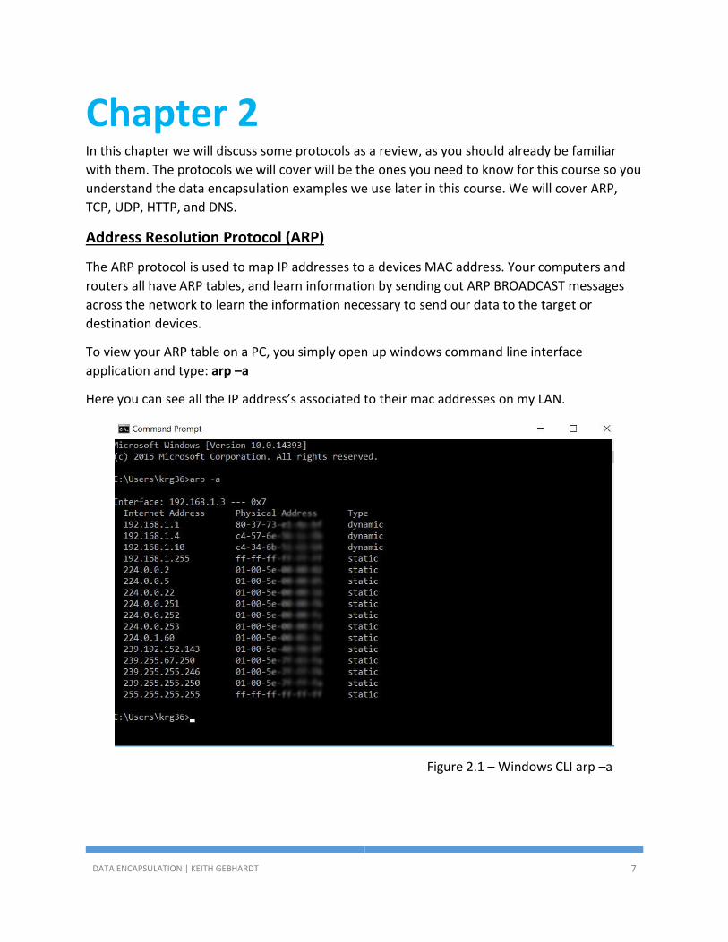
To view your ARP table on a PC, you simply open up windows command line interface
application and type: arp –a
Here you can see all the IP address’s associated to their mac addresses on my LAN.
Figure 2.1 – Windows CLI arp –a

DATA ENCAPSULATION | KEITH GEBHARDT 8
To view your ARP table on your router, you simply log into your router and navigate to
privileged mode. Once in privileged mode type in: show arp
Figure 2.2 – Router ARP Table, show arp command
ARP Broadcasts
ARP Broadcasts are a broadcast message that uses the Mac Address FFFF.FFFF.FFFF.
When a transmitting device (SOURCE) is trying to reach a device on the network to receive
(DESTINATION) the information and it does not know how to reach it, it will send out the ARP
Broadcast message using the FFFF.FFFF.FFFF address.
When devices on the network see this information, they start comparing the IP Address it is
trying to reach to their ip address, if it matches, then the device replies back with their mac
address.

DATA ENCAPSULATION | KEITH GEBHARDT 9
The important thing to remember here is that Routers are the only network device that
separate Broadcast Domains. So, your ARP Broadcast will never go beyond your default
gateway router.
In figure 2.3 below, we will say PC Bob (192.168.1.10) is trying to figure out where SERVER Larry
(192.168.1.20) is on our network, so they can communicate together.
1.) Bob will type in the IP Address of Larry in his browser
2.) Since Bobs PC’s ARP Table is empty, Bobs PC generates an ARP Broadcast which will go
out to every device on the network, but the one it came from.
3.) PC Sally will receive the message, notice the IP Address is not hers and simply discard
the message.
4.) SERVER Larry will receive the message, notice the IP Address is for him and reply back
saying, yes this is me. You need my mac address and sends his mac address to Bob.
5.) Once Bob receives the Mac Address information he will then put it in his PC’s ARP table
the IP and MAC address for SERVER Larry. Once this happens, any time they try to
communicate in the future, it will not need to waste time sending out the ARP broadcast
because the information is now stored in the ARP table on Bobs PC.
Figure 2.3 – ARP Broadcast Example

DATA ENCAPSULATION | KEITH GEBHARDT 10
Application Layer Protocols
There are many Application Layer Protocols out there, and for your CCNA exam you should
know the ones in figure 2.4.
Figure 2.4 – Common Protocols, CCENT/CCNA
For this course, we are only going to be focused on DNS and HTTP as those are going to be the
two we use to show the data encapsulation process in our examples later in this course.
DNS – Domain Name System: Protocol used to map Domain Names to their associated IP
addresses. Uses TCP or UDP and uses port 53.
HTTP – Hypertext Transfer Protocol: Protocol used to establish a connection to a web server.
Uses TCP and port 80.
As you study the protocols, it’s important to remember which transport layer protocol they are
using and which port number they need to establish a connection. Without that information,
it’s useless to even study the protocols because the whole point is being able to read the packet
information and decipher the data content. You will need to know the common protocols in
Figure 2.4 for your CCENT and CCNA exams.

DATA ENCAPSULATION | KEITH GEBHARDT 11
Transport Layer Protocols
We use our Transport layer protocols to establish a connection with another device on our
network. Pending on which application layer protocol is being used, determines which protocol
the transport layer will choose. We have two transport layer protocols.
TCP – Transmission Control Protocol: Connection Orientated protocol that provides reliability of
data being sent across the network. Uses 3 way handshake to establish connections.
UDP – User Datagram Protocol: Connection-less protocol that provides unreliable transmission
of data being sent across the network.
Although UDP does not guarantee the delivery of data across the network, it does not make it a
bad protocol. In fact, it is a great protocol as it doesn’t require as much overhead as TCP does.
Depending on the application, will determine whether or not it needs that reliability or not.
Even though TCP has more overhead, the speed is hardly noticeable to the human eye just
sitting at your computer.
Our layer 4 Segment in our Data Encapsulation process will use a source and destination port
number to make a connection possible.
We have “Known Ports” which are the ports to the common protocols in figure 2.4 – which
range from 1 to 1024. These ports cannot be changed!
We also have “Registered Open Ports” which are ports that are open for our computers and
devices to automatically assign us a port, or in certain cases allow us to choose the port we
want to use. These ports range from 1025 to 49152.
These protocols and ports are standards set by the iANA organization and for a complete listing
you should visit their web site.
Protocol and Port Standards | iANA Organization
Take a look at the network in Figure 2.5. We can see the port numbers on the PC and Server.

DATA ENCAPSULATION | KEITH GEBHARDT 12
Figure 2.5 – Network Diagram for Encapsulation
Notice how in Figure 2.6 the Source and Destination Port number information was now learned.
We use port 80 as the destination port because that is the “Known Port” for HTTP. You can see
we use port 1036 as our source port because that is the port our computer gave us.
All the information in the Orange is considered our Segment Header.
Figure 2.6 – Data Encapsulation, Segment Header

DATA ENCAPSULATION | KEITH GEBHARDT 13
Chapter 3 There are a variety of different network devices in the industry you can select from to build you
networks. For you CCENT or CCNA exams, you will only need to know about Hubs, Bridges,
Switches, and Routers. Your CCNA Routing and Switching exam will briefly discuss VoIP and
QoS, and will also briefly touch on Wireless. Since the focus for this course is Data
Encapsulation you will only be understanding the Data Encapsulation Process through Switches
and Routers.
In my “Cisco Networking Introduction” Course available on Udemy.com, you will learn more
about these network devices, however you will still only learn the basics. I will make an
announcement when my full CCNA course is completed and available at which point when you
receive the promotion notification, you will receive a coupon to receive it at a discounted price.
This full CCNA course will cover all the networking devices in a lot more detail.
Figure 3.1 – Cisco Switch and Router Comparison
Routers
Routers are Layer 3 devices that use the IP protocol to forward our data in a network, through a
network, or to a different network. Routers are the only network device that allows us to
communicate to other networks, and separate broadcast domains. Looking at figure 3.1 you
can see the 2801 router is similar to the 2960 switch, but it has a lot less ports. That is
deliberate as you would not want to have so many routers on your network, the cost would just
be ridiculous.
Routers learn where to forward this information through our layer 3 Packets in our Data
Encapsulation Process, which would include the destination IP Address of where the data is
being sent to. The Source IP address will be the device sending out the information.
Looking back at Figure 2.5, we are going to use the same network topology for this example. In
Figure 3.2 you can see how the Packet Header information was filled in with the source and
destination IP address information.

DATA ENCAPSULATION | KEITH GEBHARDT 14
Figure 3.2 – Data Encapsulation, Packet Header
Switches
Switches are Layer 2 devices that use the Ethernet protocol to forward our data in our LAN’s.
Switches learn mac addresses associated to their port numbers to build a mac address table in
its memory to use logic to determine which port to forward our data out of. Every single port
on a switch is also considered its own collision domain.
Switches learn the Mac Address information through our layer 2 frames in our Data
Encapsulation Process, which would include the source and destination Mac Address where the
data is being sent to. The source IP address will be the interface that is forwarding out data.
That is important to remember!
If you have PC Bob and you’re communicating to Server Larry on the same subnet, the source
mac address will be PC Bob and the destination mac address will be Server Larry.
Again, using the network topology example from Figure 2.5, we can see in Figure 3.3 below how
the source and destination Mac Address information was added into our Frame Header. You
can also see how we obtained a Trailer with the Frame Check Sequence field.
Figure 3.3 – Data Encapsulation, Frame Header and Trailer

DATA ENCAPSULATION | KEITH GEBHARDT 15
Chapter 4 Now that you are reacquainted with some basic fundamentals, and you were introduced to
some basic data encapsulation concepts in the previous chapters, we can now dive into the
Data Encapsulation Process In more detail.
We will use the new topology in Figure 4.1 for this chapter.
Figure 4.1 – Data Encapsulation Topology
Let’s begin by going back to our Segment, Packet, and Frame and dig into them in a little more
detail.
Figure 4.2 – Data Encapsulation: Segment, Packet, Frame

DATA ENCAPSULATION | KEITH GEBHARDT 16
Segment, Packet, Frame
Segments are our Layer 4 Data Encapsulation Headers, and include:
Source Port #
Destination Port #
Figure 4.3 – Segment and Data
Packets are our Layer 3 Data Encapsulation Headers, encapsulate all of our Segment
information and Data, and include:
Source IP Address
Destination IP Address
Figure 4.4 – Packet and Data

DATA ENCAPSULATION | KEITH GEBHARDT 17
Frames are our Layer 2 Data Encapsulation Header and Trailer, encapsulating all of Packet
information and Data, and include:
Source Mac Address
Destination Mac Address
FCS Trailer
Figure 4.5 – Frame and Data
As the information gets encapsulated from Application layer down to the Physical layer, the
information continues to get encapsulated inside of each data block. Its important to know that
none of the information is removed, essentially it is like putting change in a container, and
putting the lid on it where change represents the information in our header, and the closed
container represents the data block.
Figure 4.6 is another graphical representation that better represents of all the information
together.

DATA ENCAPSULATION | KEITH GEBHARDT 18
Figure 4.6 – Data Encapsulation Graphical Representation
Figure 4.7 is an actual graphical representation of the data encapsulation information, however
for this course we will not go into that much detail.
Take notice of the names of the different Segments, Packets, and Frames. The bottom where it
says TCP would be your Segment. The Middle where it says IP would be your Packet, and the
Top that says Ethernet will be your Frame.

DATA ENCAPSULATION | KEITH GEBHARDT 19
Figure 4.7 – Actual encapsulation example

DATA ENCAPSULATION | KEITH GEBHARDT 20
Chapter 5 Now that you understand how the data encapsulation process works, and how each of the
Segment, Packet, and Frame headers are obtaining their information, you need to understand
how the frames are being sent across multiple networks.
So far we have only seen a frame sent on a local area network and not to a router. Remember
routers are the only network device that break up broadcast domains. For a frame to reach a
router and for that packet to be sent across the network to another network, the router has
some work to do.
First, when we type in our URL the IP address of Server 172.16.5.12, the computer compares
the subnet to its own ip address configured on its network adapter. Once it realizes it is in a
different subnet the computer knows to send the data to the default gateway.
At this point our source Mac Address will be the PC 172.16.4.10. The destination Mac Address
will be the Fa0/0 port on the router since that is the physical interface we need to reach before
we can access any other part of the network.
Once the router receives the frame, it removes the frame header to examine the packet
information. The router now compares the destination IP address to its routing table and
decides where to forward the information next.
Once it knows the IP Route it needs to take, it builds a new Frame using the Mac Address of the
interface the router is forwarding the information out of. In our example, it will be Fa0/1. That
Mac Address will now become our Source Mac address because the router is now the sending
device. The servers mac address will now become the destination mac address.
We will go over a few different examples of this in the video lectures as it is very important to
understand. You can expect to see a variety of questions on your Cisco certification related to
data encapsulation across networks.
I hope you found this eBook to be a helpful companion to the Data Encapsulation 101 course
available on udemy.com!
Thank you,
Keith Gebhardt