Data Domain Hardware Features and Specifications
208
Dell EMC Data Domain Hardware Features and Specifications Guide Version 6.2 302-004-902 REV 02
Transcript of Data Domain Hardware Features and Specifications

Dell EMC Data Domain Hardware Featuresand Specifications GuideVersion 6.2
302-004-902
REV 02

Copyright © 2018 Dell Inc. or its subsidiaries. All rights reserved.
Published December 2018
Dell believes the information in this publication is accurate as of its publication date. The information is subject to change without notice.
THE INFORMATION IN THIS PUBLICATION IS PROVIDED “AS-IS.“ DELL MAKES NO REPRESENTATIONS OR WARRANTIES OF ANY KIND
WITH RESPECT TO THE INFORMATION IN THIS PUBLICATION, AND SPECIFICALLY DISCLAIMS IMPLIED WARRANTIES OF
MERCHANTABILITY OR FITNESS FOR A PARTICULAR PURPOSE. USE, COPYING, AND DISTRIBUTION OF ANY DELL SOFTWARE DESCRIBED
IN THIS PUBLICATION REQUIRES AN APPLICABLE SOFTWARE LICENSE.
Dell Technologies, Dell, EMC, Dell EMC and other trademarks are trademarks of Dell Inc. or its subsidiaries. Other trademarks may be the property
of their respective owners. Published in the USA.
Dell EMCHopkinton, Massachusetts 01748-91031-508-435-1000 In North America 1-866-464-7381www.DellEMC.com
2 Data Domain Hardware Features and Specifications Guide 6.2

9
13
DD2200 17DD2200 system features.............................................................................18DD2200 system specifications.................................................................... 18DD2200 storage capacity............................................................................19Front panel................................................................................................. 20
Disk drives..................................................................................... 20Front LED indicators......................................................................20
Back panel...................................................................................................21Power supply units......................................................................... 21Onboard interfaces and LEDs........................................................ 22
I/O modules and slot assignments.............................................................. 23FC I/O module option.................................................................... 23Ethernet I/O module options......................................................... 23
Internal system components.......................................................................24Cooling fans...................................................................................24DIMM modules.............................................................................. 25
DD2500 27DD2500 system features............................................................................28System specifications.................................................................................29DD2500 storage capacity........................................................................... 29Front panel................................................................................................. 30
Disk drives..................................................................................... 30Front LED indicators......................................................................30
Back panel.................................................................................................. 32Power supply units........................................................................ 32Onboard interfaces and LEDs........................................................ 33
I/O modules and slot assignments.............................................................. 34FC I/O module option.................................................................... 34Ethernet I/O module options......................................................... 34
Internal system components.......................................................................34Cooling fans...................................................................................35DIMM modules.............................................................................. 35
DD3300 37DD3300 system features............................................................................ 38DD3300 system specifications................................................................... 39DD3300 storage capacity........................................................................... 40Front panel..................................................................................................41
Left control panel........................................................................... 41Right control panel........................................................................ 43Front disks.....................................................................................45Service tag.................................................................................... 45
Figures
Tables
Chapter 1
Chapter 2
Chapter 3
CONTENTS
Data Domain Hardware Features and Specifications Guide 6.2 3

Rear panel..................................................................................... 46Rear panel...................................................................................................51
Product serial number tag (PSNT)................................................ 53Rear SSD.......................................................................................53NIC indicators................................................................................54Power supply indicators................................................................ 55
DD4200 57DD4200 system features............................................................................58DD4200 system specifications................................................................... 59DD4200 storage capacity........................................................................... 60Front Panel................................................................................................. 61
Power supply units......................................................................... 61AC power extender module............................................................ 61Cooling Fans..................................................................................62Solid-state drives...........................................................................62Front LED Indicators......................................................................62
Back Panel................................................................................................. 65I/O module LEDs........................................................................... 65Management module and interfaces..............................................65
I/O modules and slot assignments.............................................................. 67Slot addition rules.......................................................................... 67
Internal system components.......................................................................69DIMM modules.............................................................................. 69
DD4500 71DD4500 system features............................................................................ 72DD4500 system specifications....................................................................73DD4500 storage capacity........................................................................... 74Front Panel.................................................................................................75
Power supply units........................................................................ 75AC power extender module............................................................75Cooling Fans.................................................................................. 76Solid-state drives...........................................................................76Front LED Indicators......................................................................76
Back Panel..................................................................................................79I/O module LEDs........................................................................... 79Management module and interfaces.............................................. 79
I/O modules and slot assignments...............................................................81Slot addition rules.......................................................................... 81
Internal system components.......................................................................83DIMM modules.............................................................................. 83
DD6300 85DD6300 system features............................................................................86DD6300 system specifications....................................................................87DD6300 storage capacity........................................................................... 87DD6300 front panel....................................................................................88
Front LED indicators......................................................................89Back panel...................................................................................................91
DD6300 rear SSDs......................................................................... 91Rear LED indicators........................................................................91
I/O modules................................................................................................94I/O module population rules...........................................................95
Chapter 4
Chapter 5
Chapter 6
CONTENTS
4 Data Domain Hardware Features and Specifications Guide 6.2

Internal system components.......................................................................97DIMMs overview............................................................................97
DD6800 99DD6800 system features.......................................................................... 100DD6800 system specifications...................................................................101DD6800 storage capacity.......................................................................... 101DD6800 front panel.................................................................................. 102
Front LED indicators.................................................................... 103Back panel.................................................................................................104
Rear LED indicators......................................................................104I/O modules.............................................................................................. 107
I/O module population rules......................................................... 108Internal system components...................................................................... 110
DIMMs overview........................................................................... 110
DD7200 113DD7200 system features........................................................................... 114DD7200 system specifications...................................................................115DD7200 storage capacity.......................................................................... 116Front Panel................................................................................................ 117
Power supply units........................................................................ 117AC power extender module........................................................... 117Cooling Fans................................................................................. 118Solid-state drives..........................................................................118Front LED Indicators..................................................................... 118
Back Panel................................................................................................. 121I/O module LEDs...........................................................................121Management module and interfaces............................................. 121
I/O modules and slot assignments.............................................................123Slot addition rules.........................................................................123
Internal system components..................................................................... 125DIMM modules............................................................................. 125
DD9300 127DD9300 system features...........................................................................128DD9300 system specifications.................................................................. 129DD9300 storage capacity..........................................................................129DD9300 front panel...................................................................................130
Front LED indicators..................................................................... 131Back panel.................................................................................................132
Rear LED indicators......................................................................132I/O modules.............................................................................................. 135
I/O module population rules......................................................... 136Internal system components..................................................................... 138
DIMMs overview.......................................................................... 138
DD9500 141System features........................................................................................142System specifications............................................................................... 143DD9500 storage capacity..........................................................................144Front panel................................................................................................146
Front LED indicators.................................................................... 146
Chapter 7
Chapter 8
Chapter 9
Chapter 10
CONTENTS
Data Domain Hardware Features and Specifications Guide 6.2 5

Solid-state drives......................................................................... 149Rear panel.................................................................................................150
Power supply units........................................................................151Management module.................................................................... 151Rear LED indicators......................................................................152Available I/O modules...................................................................154Ethernet I/O module options........................................................155Fibre Channel I/O modules...........................................................155SAS I/O modules..........................................................................155
I/O module slot assignments.....................................................................155Slot addition rules.........................................................................157
Internal System Components.................................................................... 158DIMM modules............................................................................. 160Cooling fans................................................................................. 160
DD9800 161DD9800 system features.......................................................................... 162DD9800 system specifications.................................................................. 163DD9800 storage capacity..........................................................................164DD9800 front panel.................................................................................. 166
Front LED indicators.................................................................... 166Solid-state drives......................................................................... 169
Rear panel................................................................................................. 170Power supply units........................................................................ 171Management module.....................................................................171Rear LED indicators......................................................................172Available I/O modules................................................................... 174Ethernet I/O module options........................................................ 175Fibre Channel I/O modules........................................................... 175SAS I/O modules..........................................................................175
I/O module slot assignments..................................................................... 175Slot addition rules.........................................................................176
Internal system components..................................................................... 178DIMM modules............................................................................. 180Cooling fans................................................................................. 180
ES30 181ES30 overview.......................................................................................... 182ES30 site requirements............................................................................. 182ES30 hardware specifications................................................................... 183Front panel................................................................................................184Back panel................................................................................................ 185Ports......................................................................................................... 188
DS60 189DS60 overview..........................................................................................190DS60 site requirements............................................................................ 190DS60 hardware specifications................................................................... 191DS60 front panel ......................................................................................192Back panel.................................................................................................193Disk enclosure interior ..............................................................................194Expansion shelf cables.............................................................................. 197Ports......................................................................................................... 198
Chapter 11
Chapter 12
Chapter 13
CONTENTS
6 Data Domain Hardware Features and Specifications Guide 6.2

FS15 199Overview of FS15 SSD drives................................................................... 200Site requirements.....................................................................................200FS15 hardware specifications....................................................................201FS15 front panel....................................................................................... 202Back panel................................................................................................204Status LEDs............................................................................................. 206
Chapter 14
CONTENTS
Data Domain Hardware Features and Specifications Guide 6.2 7

CONTENTS
8 Data Domain Hardware Features and Specifications Guide 6.2

Front panel components.............................................................................................20Disk and system LEDs................................................................................................ 20Bezel showing lighted system power LED................................................................... 21Features on rear of chassis......................................................................................... 21Power supply unit LEDs.............................................................................................. 22Onboard interfaces and LEDs..................................................................................... 22Top view of SP module ( system shown)....................................................................24Top view of SP module with air ducts removed.......................................................... 25Front panel components.............................................................................................30Disk and system LEDs................................................................................................. 31Bezel showing lighted system power LED................................................................... 31Features on rear of chassis.........................................................................................32Power supply unit LEDs.............................................................................................. 32Onboard interfaces and LEDs..................................................................................... 33Top view of SP module ( system shown)....................................................................35Top view of SP module with air ducts removed.......................................................... 35Front panel..................................................................................................................41Left control panel....................................................................................................... 42Right control panel..................................................................................................... 44Disk LEDs................................................................................................................... 45Service tag................................................................................................................. 46Rear panel.................................................................................................................. 46PSNT location............................................................................................................ 48Disk LEDs................................................................................................................... 49NIC LEDs....................................................................................................................49Power supply LED...................................................................................................... 50Rear panel...................................................................................................................51PSNT location............................................................................................................ 53Disk LEDs................................................................................................................... 53NIC LEDs....................................................................................................................54Power supply LED...................................................................................................... 55Front panel components..............................................................................................61System LEDs.............................................................................................................. 62System LED legend label............................................................................................ 63Power supply LEDs.....................................................................................................63Fan and SSD LEDs......................................................................................................64Features on rear of chassis.........................................................................................65Interfaces on the management module.......................................................................66Top view of SP module with SP cover removed......................................................... 69Front panel components............................................................................................. 75System LEDs.............................................................................................................. 76System LED legend label.............................................................................................77Power supply LEDs..................................................................................................... 77Fan and SSD LEDs......................................................................................................78Features on rear of chassis......................................................................................... 79Interfaces on the management module.......................................................................80Top view of SP module with SP cover removed......................................................... 83Front LED indicators...................................................................................................89Rear LED indicators.................................................................................................... 91I/O module Power/Service LED location.................................................................... 93Onboard network port LEDs....................................................................................... 94I/O module slot numbering......................................................................................... 94CPU and memory locations.........................................................................................97
1234567891011121314151617181920212223242526272829303132333435363738394041424344454647484950515253
FIGURES
Data Domain Hardware Features and Specifications Guide 6.2 9

Front LED indicators................................................................................................. 103Rear LED indicators.................................................................................................. 104I/O module Power/Service LED location...................................................................106Onboard network port LEDs......................................................................................107I/O module slot numbering........................................................................................ 107CPU and memory locations........................................................................................110Front panel components............................................................................................ 117System LEDs............................................................................................................. 118System LED legend label............................................................................................119Power supply LEDs.................................................................................................... 119Fan and SSD LEDs.................................................................................................... 120Features on rear of chassis........................................................................................ 121Interfaces on the management module..................................................................... 122Top view of SP module with SP cover removed........................................................ 125Front LED indicators.................................................................................................. 131Rear LED indicators...................................................................................................132I/O module Power/Service LED location...................................................................134Onboard network port LEDs......................................................................................135I/O module slot numbering........................................................................................135CPU and memory locations....................................................................................... 138Front panel components............................................................................................146Service LEDs............................................................................................................. 147Power button............................................................................................................ 148Front LEDs................................................................................................................ 148SSD drives................................................................................................................ 149Features on rear of chassis....................................................................................... 150Serial number tag location.........................................................................................150Four power supplies................................................................................................... 151Management module.................................................................................................1521000BaseT Ethernet ports........................................................................................ 152Rear LEDs................................................................................................................. 153Power supply LEDs................................................................................................... 153Location of NVRAM and I/O modules....................................................................... 156SP module ................................................................................................................159Releasing a memory riser ......................................................................................... 159Open fan tray............................................................................................................ 160Front panel components........................................................................................... 166Service LEDs............................................................................................................. 167Power button............................................................................................................ 168Front LEDs................................................................................................................ 168SSD drives................................................................................................................ 169Features on rear of chassis........................................................................................170Serial number tag location.........................................................................................170Four power supplies................................................................................................... 171Management module..................................................................................................1711000BaseT Ethernet ports.........................................................................................172Rear LEDs................................................................................................................. 173Power supply LEDs....................................................................................................173Location of NVRAM and I/O modules........................................................................175SP module ................................................................................................................ 178Releasing a memory riser ..........................................................................................179Open fan tray............................................................................................................ 179ES30 front panel (bezel removed)............................................................................ 184Front panel LEDs.......................................................................................................184Back panel: Power modules and controllers.............................................................. 186Power Supply A LEDs................................................................................................187
54555657585960616263646566676869707172737475767778798081828384858687888990919293949596979899100101102103104105106107108109
FIGURES
10 Data Domain Hardware Features and Specifications Guide 6.2

DS60 front panel.......................................................................................................192DS60 back panel ...................................................................................................... 193Fans and disk drives inside the disk enclosure........................................................... 194Drives as packs......................................................................................................... 196HD-mini-SAS connector............................................................................................198FS15 front panel (bezel removed)............................................................................ 202Front panel LEDs...................................................................................................... 203Back panel: Power modules and controllers..............................................................204Power Supply A LEDs...............................................................................................205Rear panel overview................................................................................................. 206
110111112113114115116117118119
FIGURES
Data Domain Hardware Features and Specifications Guide 6.2 11

FIGURES
12 Data Domain Hardware Features and Specifications Guide 6.2

DD2200 system features.............................................................................................18System operating environment................................................................................... 19DD2200 storage capacity............................................................................................19Indicator states........................................................................................................... 21Indicator status...........................................................................................................22slot assignments......................................................................................................... 23DD2500 system features............................................................................................28Fundamental features.................................................................................................29DD2500 storage capacity........................................................................................... 29Indicator states........................................................................................................... 31Indicator status...........................................................................................................33slot assignments......................................................................................................... 34DD3300 system features............................................................................................ 38DD3300 system specifications....................................................................................39System operating environment...................................................................................39DD3300 storage capacity........................................................................................... 40Front disk slot numbers...............................................................................................41Rear disk slot numbers................................................................................................47Network daughter card port identifiers.......................................................................47Optional 10 GbE module port identifiers......................................................................48Optional 16 Gbps FC module port identifiers...............................................................48Rear disk slot numbers............................................................................................... 52Network daughter card port identifiers...................................................................... 52Optional 10 GbE module port identifiers..................................................................... 52Optional 16 Gbps FC module port identifiers...............................................................53DD4200 system features............................................................................................58DD4200 system specifications................................................................................... 59System operating environment...................................................................................59DD4200 storage capacity........................................................................................... 60LED status indicators..................................................................................................64DD4200 slot assignments........................................................................................... 67DD4500 system features............................................................................................ 72DD4500 system specifications....................................................................................73System operating environment................................................................................... 73DD4500 storage capacity........................................................................................... 74LED status indicators..................................................................................................78DD4500 slot assignments............................................................................................81DD6300 system features............................................................................................86DD6300 system specifications....................................................................................87System operating environment................................................................................... 87DD6300 storage capacity........................................................................................... 87DD6300 AIO capacity................................................................................................. 88DD6300 AIO configuration..........................................................................................89DD6300 AIO expanded configuration..........................................................................89Front LEDs................................................................................................................. 89DD6300 I/O slot module mapping.............................................................................. 95I/O module slot population rules.................................................................................96DD6300 memory DIMM configuration........................................................................ 97Memory locations - CPU 0..........................................................................................97Memory locations - CPU 1.......................................................................................... 98DD6800 system features.......................................................................................... 100DD6800 system specifications...................................................................................101System operating environment.................................................................................. 101
1234567891011121314151617181920212223242526272829303132333435363738394041424344454647484950515253
TABLES
Data Domain Hardware Features and Specifications Guide 6.2 13

DD6800 storage capacity.......................................................................................... 101DD6800 DLH SSD requirements............................................................................... 102DD6800 DLH configuration drive layout.................................................................... 102DD6800 DLH expanded configuration drive layout.................................................... 102Front LEDs................................................................................................................ 103DD6800 I/O module slot mapping............................................................................. 108I/O module slot population rules................................................................................109DD6800 memory DIMM configuration....................................................................... 110Memory locations - CPU 0.........................................................................................110Memory locations - CPU 1.......................................................................................... 111DD7200 system features........................................................................................... 114DD7200 system specifications................................................................................... 115System operating environment.................................................................................. 115DD7200 storage capacity...........................................................................................116LED status indicators................................................................................................ 120DD7200 slot assignments.......................................................................................... 123DD9300 system features...........................................................................................128DD9300 system specifications.................................................................................. 129System operating environment................................................................................. 129DD9300 storage capacity..........................................................................................129DD9300 DLH SSD requirements............................................................................... 130DD9300 DLH configuration drive layout.................................................................... 130DD9300 DLH expanded configuration drive layout.................................................... 130Front LEDs.................................................................................................................131DD9300 I/O module slot mapping............................................................................. 136I/O module slot population rules................................................................................ 137DD9300 memory DIMM configuration.......................................................................138Memory locations - CPU 0........................................................................................ 138Memory locations - CPU 1.........................................................................................139DD9500 system features...........................................................................................142DD9500/DD9800 system specifications................................................................... 143DD9500 storage capacity..........................................................................................144DD9500 with ES30 SAS shelves............................................................................... 145DD9500 with DS60 shelves.......................................................................................145Front panel LED status indicators............................................................................. 149Rear LED status indicators........................................................................................ 153Physical to logical port mapping example.................................................................. 154DD9500 I/O module slot assignments....................................................................... 156I/O module slot population rules................................................................................157DD9500 memory configurations............................................................................... 160DD9800 system features...........................................................................................162DD9800 system specifications.................................................................................. 163DD9800 storage capacity..........................................................................................164DD9800 with ES30 SAS shelves............................................................................... 165DD9800 with DS60 shelves.......................................................................................165Front panel LED status indicators............................................................................. 169Rear LED status indicators........................................................................................ 173Physical to logical port mapping example.................................................................. 174DD9800 I/O module slot assignments....................................................................... 176I/O module slot population rules................................................................................ 177DD9800 memory configurations................................................................................180ES30 shelves in a set.................................................................................................182ES30 site requirements............................................................................................. 182ES30 hardware specifications................................................................................... 183Status lights visible from front of disk enclosure.......................................................185Status lights visible from rear of disk enclosure ........................................................187
54555657585960616263646566676869707172737475767778798081828384858687888990919293949596979899100101102103104105106107108109
TABLES
14 Data Domain Hardware Features and Specifications Guide 6.2

DS60 shelf set support............................................................................................. 190Site requirements......................................................................................................190Hardware specifications.............................................................................................191LED status lights....................................................................................................... 192Status lights visible from rear of disk enclosure ....................................................... 193LED status lights....................................................................................................... 195Physical drives.......................................................................................................... 196HD-mini-SAS to mini-SAS cable part numbers.......................................................... 198HD-mini-SAS to ES30 host and ES30 expansion port cable part numbers................ 198Number of SSD drives and Data Domain model compatibilty....................................200FS15 site requirements............................................................................................. 200FS15 hardware specifications....................................................................................201Status lights visible from front of disk enclosure...................................................... 203Status lights visible from rear of disk enclosure .......................................................205Status LEDs..............................................................................................................206
110111112113114115116117118119120121122123124
TABLES
Data Domain Hardware Features and Specifications Guide 6.2 15

TABLES
16 Data Domain Hardware Features and Specifications Guide 6.2

CHAPTER 1
DD2200
l DD2200 system features.................................................................................... 18l DD2200 system specifications............................................................................18l DD2200 storage capacity................................................................................... 19l Front panel.........................................................................................................20l Back panel.......................................................................................................... 21l I/O modules and slot assignments......................................................................23l Internal system components.............................................................................. 24
DD2200 17

DD2200 system featuresThis table summarizes the system features of the DD2200.
Table 1 DD2200 system features
Feature DD2200 (Baseconfiguration)
DD2200 (Expandedconfiguration)
Rack height 2U, supported in four-postracks only
2U, supported in four-postracks only
Rack mounting Rack mount kit included witheach system. Adjustablebetween 18 - 36 in. (45.7–76.2 cm).
Rack mount kit included witheach system. Adjustablebetween 18 - 36 in. (45.7–76.2 cm).
Power 1 +1 redundant, hot-swappable power units
1 +1 redundant, hot-swappable power units
Processor One 6-core processor One 6-core processor
NVRAM System memory-BBUmodule-hard disk drivecombination for data integrityduring a power outage.
System memory-BBUmodule-hard disk drivecombination for data integrityduring a power outage.
BBU module One BBU module for dataintegrity during a poweroutage. Not hot-swappable.
One BBU module for dataintegrity during a poweroutage. Not hot-swappable.
Fans Seven fan assemblies. Nothot-swappable.
Seven fan assemblies. Nothot-swappable.
Memory 2 x 4 GB DIMM (8 GB) 4 x 4 GB DIMM (16 GB)
Internal drives Seven 2-TB HDD hot-swappable drives.
Twelve 2-TB HDD hot-swappable drives.
I/O module slots Two replaceable I/O module(FC and Ethernet) slots.Not hot-swappable.
Two replaceable I/O module(FC and Ethernet) slots.Not hot-swappable.
DD2200 system specificationsModel Watts BTU/
hourPower (VA)(120V/230V)
Size(U)
Powerconnectors
Weight Width Depth Height
DD2200with 7drives
394 1345 406 (3.38A/1.76A)
2 2 x grounded 65 lb /29.5 kg
19 in /48.3 cm
29.5 in /74.9 cm
3.5 in / 8.9cm
DD2200with 12drives
487 1662 502 (4.18A/2.18A)
2 2 x grounded 73 lb /33.1 kg
19 in /48.3 cm
29.5 in /74.9 cm
3.5 in / 8.9cm
DD2200
18 Data Domain Hardware Features and Specifications Guide 6.2

Table 2 System operating environment
Operating Temperature 50° to 95° F (10° to 35° C), derate 1.1° Cper 1,000 feet, above 7500 feet up to 10,000feet
Operating Humidity 20% to 80%, non-condensing
Non-operating Temperature -40° to +149° F (-40° to +65° C)
Operating Acoustic Noise Sound power, LWAd: 7.52 bels. Soundpressure, LpAm: 56.4 dB. (Declared noiseemission per ISO 9296.)
DD2200 storage capacityThe table lists the capacities of the DD2200 system. The Data Domain system internalindices and other product components use variable amounts of storage, depending onthe type of data and the sizes of files. If you send different data sets to otherwiseidentical systems, one system may, over time, have room for more or less actualbackup data than another.
Note
The system commands compute and display amounts of disk space or data as decimalmultiples of certain powers of two (210, 220, 230, and so forth). For example, 7 GiB ofdisk space = 7 x 230 bytes = 7 x 1,073,741,824 bytes. This process is referred to asBase 2 calculation.
Table 3 DD2200 storage capacity
System/InstalledMemory
InternalDisks
Data StorageSpace(Base 2Calculation)
Data StorageSpace(Base 10Calculation)
External Storage
DD22002 x 4 GBDIMM
Seven 3.5in. 2 TBSAS HDDs
7 drives: 7012 GiB 7 drives: 7531GB
NA
DD22004 x 4 GBDIMM
Seven ortwelve 3.5in. 2 TBSAS HDDs
7 drives: 7012 GiB7+5 drives: 12,356GiB
12 drives: 16,100GiB
7 drives: 7531GB7+5 drives:13,270 GB
12 drives: 17,291GB
NA
Note
For information about Data Domain expansion shelves, see the Data Domain ES30Expansion Shelf Hardware Guide and Data Domain DS60 Expansion Shelf Hardware Guide.
DD2200
DD2200 storage capacity 19

Front panelFigure 1 Front panel components
Disk drivesThe system contains up to 12 hot-swappable 3.5" HDD SAS disk drives, located in thefront of the chassis. Left to right, drives are numbered 0-3 in the top row, 4-7 in themiddle row, and 8-11 in the bottom row.
l The base configuration contains 7 disk drives in locations 0 through 6. Drive bays7-11 contain bay blanks.
l The expanded configuration contains 12 disk drives.
Front LED indicatorsThe front of the system contains 12 disk drive status LEDs that are normally blue andblink when there is activity on the disk. The LEDs are shaped like triangles, and theapex of the triangle points either left or right toward the disk whose status itrepresents. If the disk drive has a failure, the disk’s status LED turns from blue toamber.
There are two square-shaped system LEDs. A blue system power LED is on wheneverthe system has power. An amber system fault LED is normally off and is lit amberwhenever the chassis or any other FRU in the system requires service.
Figure 2 Disk and system LEDs
1. System fault LED (square shaped).2. System power LED (square shaped).3. Disk drive LEDs (triangular shaped).
DD2200
20 Data Domain Hardware Features and Specifications Guide 6.2

Table 4 Indicator states
Part State
System fault Normally unlit. Amber indicates fault.
System power Steady blue indicates normal power.
Disk drive status Steady blue or blinking blue indicates normal operation. Amberindicates fault or failure.
When the bezel is affixed, the blue system power LED can be seen through the bezel.
Figure 3 Bezel showing lighted system power LED
Back panelFigure 4 Features on rear of chassis
1. Slot 0.2. Slot 1.3. Slot 2.4. Slot 3.5. Slot 4, NVRAM-BBU combination module.6. Onboard interfaces.7. Power supply, number 0.8. Power supply, number 1.
Power supply unitsA system has two power supply units, numbered 0 and 1 from left to right. Each powerunit has LEDs (shown in the photo) that indicates the following states:
l AC LED (top): Glows green when AC input is good.
l DC LED (middle): Glows green when DC output is good.
DD2200
Back panel 21

l Symbol “!” (lower): Glows solid amber for fault or attention.
Figure 5 Power supply unit LEDs
Onboard interfaces and LEDsFigure 6 Onboard interfaces and LEDs
1. Serial number label.2. SP power LED (top); SP service LED (bottom).3. Dual-port 10GBaseT.4. Quad-port Gigabit Ethernet.5. Service network port (top); USB port (bottom).6. Serial port.
The onboard interfaces and LEDs are located at the far lower left side of the back ofthe system. The onboard interfaces enable you to check system status and connect tothe system through a serial console or Ethernet connections. The dual-port 10GBaseTand quad-port Gigabit Ethernet interfaces allow connectivity to the data host.
A USB port enables the system to boot from a USB flash device.
Rear LED status summary
Table 5 Indicator status
Part State
SP service Blue indicates normal operation. Amber indicates fault.
SP power Steady green indicates normal power. Dark indicates no power.
DD2200
22 Data Domain Hardware Features and Specifications Guide 6.2

Table 5 Indicator status (continued)
Part State
I/O module Steady green indicates normal operation. Amber indicates faultor failure.
Power supply AC Glows green when AC input is operational.
Power supply DC Glows green when DC output is operational.
Power supply symbol “!” Glows solid amber for fault or attention.
I/O modules and slot assignments
Table 6 slot assignments
Slot Number System
0 FC, Ethernet or emptyEmpty
1 FC, Ethernet or emptyEmpty
2 FC, Ethernet or emptyEmpty
3 SAS or empty
4 NVRAM-BBU
When a system is upgraded, the newly inserted I/O module must go into slot positionthree. No other slot positions should be used. Existing modules should not be removedand reinserted into different slots.
When a system is upgraded, the newly inserted I/O module should go into the nextavailable slot position. The following slot loading rules apply:
l For mixed populations, populate all Ethernet I/O modules first, then populate theFC I/O modules.
l For Ethernet I/O modules, populate the leftmost (slot 0) slot first, if empty, thenslot 1 and so on.
l Slot 3 is reserved for SAS I/O modules only.
FC I/O module optionThe FC I/O module is a dual-port Fibre Channel module. The optional virtual tapelibrary (VTL) feature requires at least one FC I/O module. Three FC I/O module slotsare available for use.
Ethernet I/O module optionsThe following Ethernet I/O modules are available:
l Dual Port 10GBase-SR Optical with LC connectors
l Dual Port 10GBase-CX1 Direct Attach Copper with SPF+ module
l Quad Port 1000Base-T Copper with RJ-45 connectors
l Quad port 2-port 1000Base-T Copper (RJ-45)/2-port 1000Base-SR Optical
You can use up to three I/O module slots for Ethernet connectivity.
DD2200
I/O modules and slot assignments 23

Internal system componentsThe photo shows the system with the storage processor (SP) module removed fromthe chassis. The top of the photo shows the rear of the system.
Figure 7 Top view of SP module ( system shown)
Cooling fansA system processor module contains seven cooling fans. The fans provide cooling forthe processor, DIMMs, and I/O modules. A system can run with one fan modulefaulted.
DD2200
24 Data Domain Hardware Features and Specifications Guide 6.2

Figure 8 Top view of SP module with air ducts removed
DIMM modulesDD2200 systems can contain either 2 x 4 GB or 4 x 4 GB memory DIMMs.
DD2200
DIMM modules 25

DD2200
26 Data Domain Hardware Features and Specifications Guide 6.2

CHAPTER 2
DD2500
l DD2500 system features................................................................................... 28l System specifications........................................................................................ 29l DD2500 storage capacity...................................................................................29l Front panel.........................................................................................................30l Back panel..........................................................................................................32l I/O modules and slot assignments......................................................................34l Internal system components.............................................................................. 34
DD2500 27

DD2500 system featuresThe table summarizes the features of the DD2500 system.
Table 7 DD2500 system features
Feature DD2500 (Baseconfiguration)
DD2500 (Expandedconfiguration)
Rack height 2U, supported in four-postracks only
2U, supported in four-postracks only
Rack mounting Rack mount kit included witheach system. Adjustablebetween 18 - 36 in. (45.7–76.2 cm).
Rack mount kit included witheach system. Adjustablebetween 18 - 36 in. (45.7–76.2 cm).
Power 1 +1 redundant, hot-swappable power units
1 +1 redundant, hot-swappable power units
Processor One 8-core processor One 8-core processor
NVRAM One 2-GB NVRAM-BBUcombination module for dataintegrity during a poweroutage. Not hot-swappable.
One 2-GB NVRAM-BBUcombination module for dataintegrity during a poweroutage. Not hot-swappable.
BBU module BBU module is combined withthe NVRAM module.
BBU module is combined withthe NVRAM module.
Fans Seven fan assemblies. Nothot-swappable.
Seven fan assemblies. Nothot-swappable.
Memory 4 x 8 GB DIMM (32 GB) 8 x 8 GB DIMM (64 GB)
Internal drives Seven 3-TB HDD hot-swappable drives.
Twelve 3-TB HDD hot-swappable drives.
External storage 1 x 30-TB SAS shelf adding upto 30 TB of external rawcapacity
4 x 30-TB SAS shelves or 3 x45-TB SAS shelves adding upto 135 TB of external rawcapacity
I/O module slots Four replaceable I/O module(FC, Ethernet, and SAS)slots.Not hot-swappable.
Four replaceable I/O module(FC, Ethernet, and SAS)slots.Not hot-swappable.
DD2500
28 Data Domain Hardware Features and Specifications Guide 6.2

System specifications
Table 8 Fundamental features
Model Watts BTU/hour
Power (VA)(120V/230V)
Size(U)
Powerconnectors
Weight Width Depth Height
with 7drives
394 1345 406 (3.38A/1.76A)
2 2 x grounded,120 VAC, NEMA15P/R
65 lb. /29.5 kg.
19 in. /48.3 cm.
29.5 in. /74.9 cm
3.5 in. /8.9 cm.
with 12drives
487 1662 502 (4.18A/2.18A)
2 2 x grounded,120 VAC, NEMA15P/R
73 lb. /33.1 kg.
19 in. /48.3 cm.
29.5 in. /74.9 cm.
3.5 in. /8.9 cm.
l Operating temperature: 50° to 95° F (10° to 35° C), derate 1.1° C per 1000 feet,above 7500 feet up to 10,000 feet.
l Operating humidity: 20% to 80%, non-condensing.
l Non-operating temperature: -40° to +149° F (-40° to +65° C).
l Operating acoustic noise: Sound power, LWAd, is 7.52 bels. Sound pressure,LpAm, is 56.4 dB. (Declared noise emission per ISO 9296.)
DD2500 storage capacityThe table lists the capacities of the DD2500 system. The Data Domain system internalindices and other product components use variable amounts of storage, depending onthe type of data and the sizes of files. If you send different data sets to otherwiseidentical systems, one system may, over time, have room for more or less actualbackup data than another.
Note
The system commands compute and display amounts of disk space or data as decimalmultiples of certain powers of two (210, 220, 230, and so forth). For example, 7 GiB ofdisk space = 7 x 230 bytes = 7 x 1,073,741,824 bytes. This process is referred to asBase 2 calculation.
Table 9 DD2500 storage capacity
System/InstalledMemory
InternalDisks
RawStorage(Base10)
Data StorageSpace(Base 2Calculation)
DataStorageSpace(Base 10Calculation)
External Storage
4 x 8 GBDIMM
Seven ortwelve 3.5in. 3 TBSAS HDDs
21 TB or36 TB
7 drives: 10,671GiB7+5 drives:18,763 GiB
7 drives:11,458 GiB7+5 drives:20147 GiB1
1 x 30-TB SAS shelf;up to 30 TB of rawcapacity.
DD2500
System specifications 29
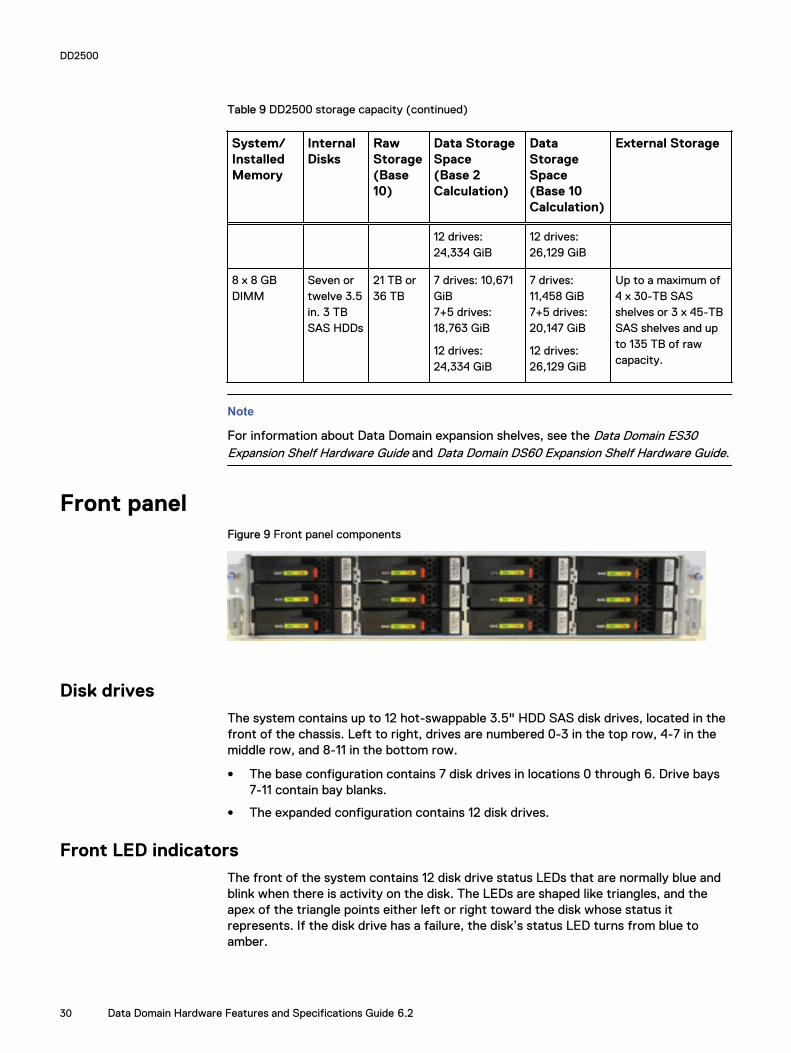
Table 9 DD2500 storage capacity (continued)
System/InstalledMemory
InternalDisks
RawStorage(Base10)
Data StorageSpace(Base 2Calculation)
DataStorageSpace(Base 10Calculation)
External Storage
12 drives:24,334 GiB
12 drives:26,129 GiB
8 x 8 GBDIMM
Seven ortwelve 3.5in. 3 TBSAS HDDs
21 TB or36 TB
7 drives: 10,671GiB7+5 drives:18,763 GiB
12 drives:24,334 GiB
7 drives:11,458 GiB7+5 drives:20,147 GiB
12 drives:26,129 GiB
Up to a maximum of4 x 30-TB SASshelves or 3 x 45-TBSAS shelves and upto 135 TB of rawcapacity.
Note
For information about Data Domain expansion shelves, see the Data Domain ES30Expansion Shelf Hardware Guide and Data Domain DS60 Expansion Shelf Hardware Guide.
Front panelFigure 9 Front panel components
Disk drivesThe system contains up to 12 hot-swappable 3.5" HDD SAS disk drives, located in thefront of the chassis. Left to right, drives are numbered 0-3 in the top row, 4-7 in themiddle row, and 8-11 in the bottom row.
l The base configuration contains 7 disk drives in locations 0 through 6. Drive bays7-11 contain bay blanks.
l The expanded configuration contains 12 disk drives.
Front LED indicatorsThe front of the system contains 12 disk drive status LEDs that are normally blue andblink when there is activity on the disk. The LEDs are shaped like triangles, and theapex of the triangle points either left or right toward the disk whose status itrepresents. If the disk drive has a failure, the disk’s status LED turns from blue toamber.
DD2500
30 Data Domain Hardware Features and Specifications Guide 6.2

There are two square-shaped system LEDs. A blue system power LED is on wheneverthe system has power. An amber system fault LED is normally off and is lit amberwhenever the chassis or any other FRU in the system requires service.
Figure 10 Disk and system LEDs
1. System fault LED (square shaped).2. System power LED (square shaped).3. Disk drive LEDs (triangular shaped).
Table 10 Indicator states
Part State
System fault Normally unlit. Amber indicates fault.
System power Steady blue indicates normal power.
Disk drive status Steady blue or blinking blue indicates normal operation. Amberindicates fault or failure.
When the bezel is affixed, the blue system power LED can be seen through the bezel.
Figure 11 Bezel showing lighted system power LED
DD2500
Front LED indicators 31

Back panelFigure 12 Features on rear of chassis
1. Slot 0.2. Slot 1.3. Slot 2.4. Slot 3.5. Slot 4, NVRAM-BBU combination module.6. Onboard interfaces.7. Power supply, number 0.8. Power supply, number 1.
Power supply unitsA system has two power supply units, numbered 0 and 1 from left to right. Each powerunit has LEDs (shown in the photo) that indicates the following states:
l AC LED (top): Glows green when AC input is good.
l DC LED (middle): Glows green when DC output is good.
l Symbol “!” (lower): Glows solid amber for fault or attention.
Figure 13 Power supply unit LEDs
DD2500
32 Data Domain Hardware Features and Specifications Guide 6.2

Onboard interfaces and LEDsFigure 14 Onboard interfaces and LEDs
1. Serial number label.2. SP power LED (top); SP service LED (bottom).3. Dual-port 10GBaseT.4. Quad-port Gigabit Ethernet.5. Service network port (top); USB port (bottom).6. Serial port.
The onboard interfaces and LEDs are located at the far lower left side of the back ofthe system. The onboard interfaces enable you to check system status and connect tothe system through a serial console or Ethernet connections. The dual-port 10GBaseTand quad-port Gigabit Ethernet interfaces allow connectivity to the data host.
A USB port enables the system to boot from a USB flash device.
Rear LED status summary
Table 11 Indicator status
Part State
SP service Blue indicates normal operation. Amber indicates fault.
SP power Steady green indicates normal power. Dark indicates no power.
I/O module Steady green indicates normal operation. Amber indicates faultor failure.
Power supply AC Glows green when AC input is operational.
Power supply DC Glows green when DC output is operational.
Power supply symbol “!” Glows solid amber for fault or attention.
DD2500
Onboard interfaces and LEDs 33

I/O modules and slot assignments
Table 12 slot assignments
Slot Number System
0 FC, Ethernet or emptyEmpty
1 FC, Ethernet or emptyEmpty
2 FC, Ethernet or emptyEmpty
3 SAS or empty
4 NVRAM-BBU
When a system is upgraded, the newly inserted I/O module must go into slot positionthree. No other slot positions should be used. Existing modules should not be removedand reinserted into different slots.
When a system is upgraded, the newly inserted I/O module should go into the nextavailable slot position. The following slot loading rules apply:
l For mixed populations, populate all Ethernet I/O modules first, then populate theFC I/O modules.
l For Ethernet I/O modules, populate the leftmost (slot 0) slot first, if empty, thenslot 1 and so on.
l Slot 3 is reserved for SAS I/O modules only.
FC I/O module optionThe FC I/O module is a dual-port Fibre Channel module. The optional virtual tapelibrary (VTL) feature requires at least one FC I/O module. Three FC I/O module slotsare available for use.
Ethernet I/O module optionsThe following Ethernet I/O modules are available:
l Dual Port 10GBase-SR Optical with LC connectors
l Dual Port 10GBase-CX1 Direct Attach Copper with SPF+ module
l Quad Port 1000Base-T Copper with RJ-45 connectors
l Quad port 2-port 1000Base-T Copper (RJ-45)/2-port 1000Base-SR Optical
You can use up to three I/O module slots for Ethernet connectivity.
Internal system componentsThe photo shows the system with the storage processor (SP) module removed fromthe chassis. The top of the photo shows the rear of the system.
DD2500
34 Data Domain Hardware Features and Specifications Guide 6.2

Figure 15 Top view of SP module ( system shown)
Cooling fansA system processor module contains seven cooling fans. The fans provide cooling forthe processor, DIMMs, and I/O modules. A system can run with one fan modulefaulted.
Figure 16 Top view of SP module with air ducts removed
DIMM modulessystems can contain either 4 x 8 GB or 8 x 8 GB memory DIMMs.
DD2500
Cooling fans 35

DD2500
36 Data Domain Hardware Features and Specifications Guide 6.2

CHAPTER 3
DD3300
l DD3300 system features....................................................................................38l DD3300 system specifications........................................................................... 39l DD3300 storage capacity...................................................................................40l Front panel......................................................................................................... 41l Rear panel.......................................................................................................... 51
DD3300 37

DD3300 system features
Table 13 DD3300 system features
Feature 4 TB configuration 8 TB configuration 16 TB configuration 32 TB configuration
RackHeight
2U, supported in four-post racks only
Power 1 or 2 hot-swappable power units
Fans 6 hot swappable fans, installed in two fan assemblies (3 fans per fan assembly)
Rackmounting
Rack mount kit included with each system. Adjustable between 24 - 36 in. (60.9–76.2 cm).
Processor 1 x 8-core Intel 4110 series, hyperthreaded
Voltage 100–240 V~. Frequency: 50 Hz to 60 Hz.
Internal3.5" drives(front)
4 x 4 TB HDD 10 x 4 TB HDD 10 x 4 TB HDD 12 x 4 TB HDD
Internal3.5" drives(middle)
N/A N/A N/A 4 x 4 TB HDD
Internal3.5" drives(rear)
N/A 1 x 480 GB SSD for NVRAMa
NIC 4 x 1 GbE or 4 x 10 GbE (always present)b + 2 x 10 GbE (optional)
FC (DDVTL only)
4 x 16 Gbps (optional)
Memory 16 GB or 24 GBc 48 GB 48 GB or 56 GBd 64 GB
a. The SSD is for use as an NVRAM device, and for SSD Cache Tier storage only. The maximum supported SSD Cache Tiercapacity is one percent of the Active Tier capacity. Other SSD-based functions such as Random I/O handling are not supportedfor use with the SSD.
b. Starting with DD OS 6.2, DD3300 systems ship with a 4 x 10 GbE RJ-45 network daughter card.c. 24 GB of memory is required to use the FC module for DD VTL.d. A 16 TB system will have 56 GB of memory if it was a 4 TB system equipped with the FC module, and was later upgraded to 16
TB.
Note
DD OS may report less storage and memory than indicated in this table. Theunreported resources are used for internal system processes.
DD3300
38 Data Domain Hardware Features and Specifications Guide 6.2

DD3300 system specifications
Table 14 DD3300 system specifications
Watts BTU/hr Weight Width Depth Height
750 2891 72.91 lb/33.1 kg 17.09 in/43.4 cm 28.17 inches/71.55cm
3.42 in/8.68 cm
Table 15 System operating environment
Operating Temperature 50° to 95° F (10° to 35° C), derate 1.1° Cper 1000 feet, above 7500 feet up to 10,000feet
Operating Humidity 20% to 80%, non-condensing
Non-operating Temperature -40° to +149° F (-40° to +65° C)
Operating Acoustic Noise Sound power, LWAd: 7.52 bels. Soundpressure, LpAm: 56.4 dB. (Declared noiseemission per ISO 9296.)
DD3300
DD3300 system specifications 39

DD3300 storage capacityThe table lists the capacities of the systems. Data Domain system internal indexes andother product components use variable amounts of storage, depending on the type ofdata and the sizes of files. If you send different data sets to otherwise identicalsystems, one system may, over time, have room for more or less actual backup datathan another.
Table 16 DD3300 storage capacity
Configuration
Internaldisks -physicalab
Internal disks -virtual
Rawstorage
Usablestorage(local)c
Cloud storage SSD metadatacache storage
4 TBcapacity /16GB memory
4 x 4 TB 7200RPM NLSAS
l 1 x 4 TB forActive Tier
l 1 x 1 TB for DDCloud Tiermetadata
16 TB 4 TB 8 TB N/A
8 TBcapacity/48GB memory
10 x 4 TB7200 RPMNLSAS
l 4 x 4 TB forActive Tier
l 2 x 1 TB for DDCloud Tiermetadata
40 TB 8 TB 16 TB 160 GB
16 TBcapacity/48GB memory
10 x 4 TB7200 RPMNLSAS
l 4 x 4 TB forActive Tier
l 2 x 1 TB for DDCloud Tiermetadata
40 TB 16 TB 32 TB 160 GB
32 TBcapacity/64GB memory
l 12 x 4 TB7200RPMNLSAS(front)
l 4 x 4 TB7200RPMNLSAS(middle)
l 8 x 4 TB forActive Tier
l 4 x 1 TB for DDCloud Tiermetadata
64 TB 32 TB 64 TB 320 GB
a. The internal physical disks are configured in a RAID6 configuration. RAID6 provides the system with the ability to withstand thesimultaneous failure of two hard drives, or the failure of one hard drive while another hard drive is still rebuilding after a drivereplacement operation.
b. After replacing a disk, it takes approximately 18 hours to complete the rebuild operation on the new disk, but may takesignificantly longer depending on the amount of activity on the system.
c. The system compensates for the required file system overhead, so the reported usable capacity matches the specified usablecapacity.
DD3300
40 Data Domain Hardware Features and Specifications Guide 6.2

Front panelThe DD3300 front panel consists of two control panels, which contain system LEDsand ports, twelve 3.5" disk drive bays, and the service tag. Figure 17 on page 41shows the locations of the front panel components.
Figure 17 Front panel
1. Left control panel2. 3.5" disk drive3. Right control panel4. Service tag.
Disk layoutThe following table shows the physical location of each disk slot.
Note
Although the physical slots are numbered starting from 0, the software identifies theslots starting at 1.
Table 17 Front disk slot numbers
Slot 0 (SW slot 1) Slot 3 (SW slot 4) Slot 6 (SW slot 7) Slot 9 (SW slot 10)
Slot 1 (SW slot 2) Slot 4 (SW slot 5) Slot 7 (SW slot 8) Slot 10 (SW slot 11)
Slot 2 (SW slot 3) Slot 5 (SW slot 6) Slot 8 (SW slot 9) Slot 11 (SW slot 12)
Left control panelThe left control panel contains system status LEDs. Figure 18 on page 42 shows thepanel.
DD3300
Front panel 41

Figure 18 Left control panel
1. System status LEDs2. System health and system ID indicator3. iDRAC Quick Sync 2 wireless indicator (Not supported)
The system status LEDs turn solid amber if the system experiences an error in any ofthe following categories. Under normal operating conditions, the system status LEDsremain off. From top to bottom, the five system status LEDs are:
l Drive indicator
l Temperature indicator
DD3300
42 Data Domain Hardware Features and Specifications Guide 6.2

l Electrical indicator
l Memory indicator
l PCIe indicator
The system health and system ID indicator has the following states:
l Solid blue: Indicator is in system health mode. System is on and healthy.
l Blinking blue: Indicator is in system ID mode.
Note
Press the System Health and System ID button to switch the indicator betweensystem health and system ID modes.
l Solid amber: System is in fail-safe mode.
l Blinking amber: System is experiencing a fault.
Right control panelThe right control panel contains the system power button, and system maintenanceports. Figure 19 on page 44 shows the panel.
DD3300
Right control panel 43
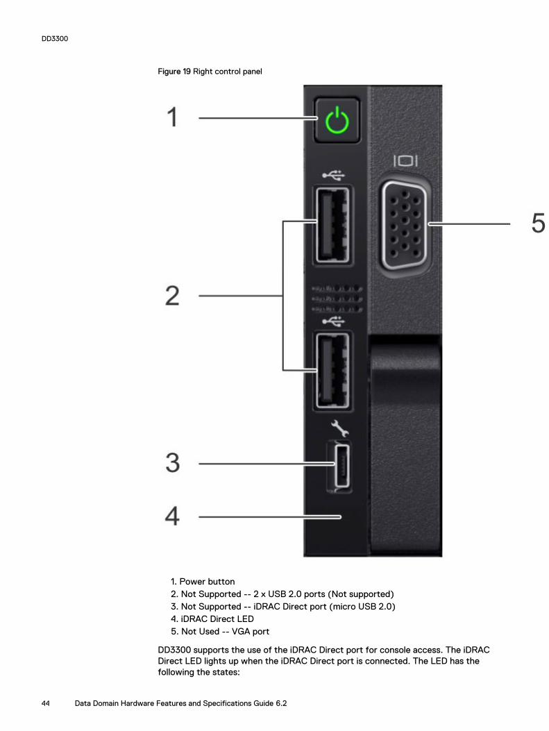
Figure 19 Right control panel
1. Power button2. Not Supported -- 2 x USB 2.0 ports (Not supported)3. Not Supported -- iDRAC Direct port (micro USB 2.0)4. iDRAC Direct LED5. Not Used -- VGA port
DD3300 supports the use of the iDRAC Direct port for console access. The iDRACDirect LED lights up when the iDRAC Direct port is connected. The LED has thefollowing the states:
DD3300
44 Data Domain Hardware Features and Specifications Guide 6.2
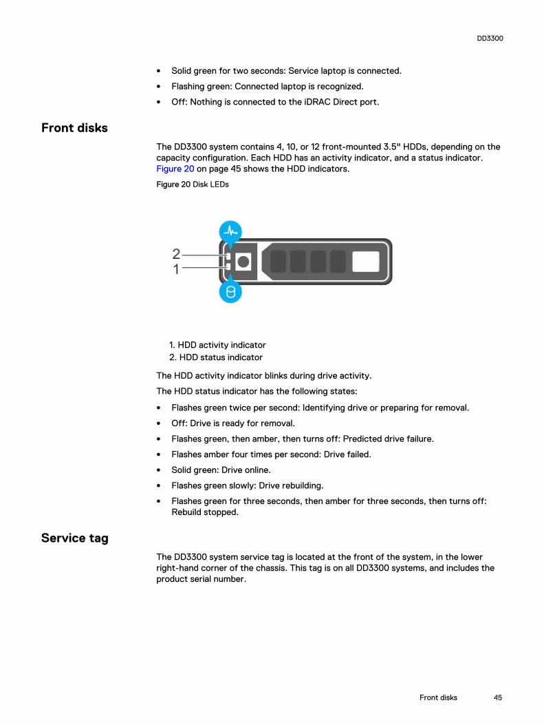
l Solid green for two seconds: Service laptop is connected.
l Flashing green: Connected laptop is recognized.
l Off: Nothing is connected to the iDRAC Direct port.
Front disksThe DD3300 system contains 4, 10, or 12 front-mounted 3.5" HDDs, depending on thecapacity configuration. Each HDD has an activity indicator, and a status indicator. Figure 20 on page 45 shows the HDD indicators.
Figure 20 Disk LEDs
1. HDD activity indicator2. HDD status indicator
The HDD activity indicator blinks during drive activity.
The HDD status indicator has the following states:
l Flashes green twice per second: Identifying drive or preparing for removal.
l Off: Drive is ready for removal.
l Flashes green, then amber, then turns off: Predicted drive failure.
l Flashes amber four times per second: Drive failed.
l Solid green: Drive online.
l Flashes green slowly: Drive rebuilding.
l Flashes green for three seconds, then amber for three seconds, then turns off:Rebuild stopped.
Service tagThe DD3300 system service tag is located at the front of the system, in the lowerright-hand corner of the chassis. This tag is on all DD3300 systems, and includes theproduct serial number.
DD3300
Front disks 45

Figure 21 Service tag
1. Information tag (top view)2. Information tag (back view)3. OpenManage Mobile (OMM) label4. iDRAC MAC address and secure password label5. Service tag
Rear panelThe DD3300 rear panel contains the system serial port, NIC cards, power supplies, and3.5" drive bays. shows the rear of the system.
Figure 22 Rear panel
1. Full height PCIe expansion card slots
l The top slot is for the optional 2 x 10 GbE NIC
l The middle slot is for the optional 4 x 16 Gbps FC module
DD3300
46 Data Domain Hardware Features and Specifications Guide 6.2

l The bottom slot is not supported
2. Not Supported -- Half height PCIe expansion card slot
3. Rear handle
4. 3.5" drive bays (used for 1 x 480 GB SSD in the 8 TB, 16 TB, and 32 TBconfigurations)
5. Power supply units (1 or 2)
6. Network daughter card Ethernet ports
7. Not Supported -- USB 3.0 ports
8. Not Supported -- VGA port
9. Serial port
10. iDRAC9 dedicated management port
11. System identification button
The DD3300 system supports the use of the iDRAC9 dedicated management port toemulate a serial console.
Disk layout8 TB, 16 TB, and 32 TB configurations use one rear slot for an SSD. 4 TBconfigurations do not use an SSD. The following table shows the physical location ofthe rear SSD slots.
Note
Although the physical slots are numbered starting from 0, the software identifies theslots starting at 1.
Table 18 Rear disk slot numbers
Slot 12 (SW slot 13) Slot 13 (SW slot 14)
Network port layoutThe DD3300 network daughter card provides 4 x 1 GbE or 4 x 10 GbE network portsfor network connectivity.
Note
Starting with DD OS 6.2, DD3300 systems ship with a 4 x 10 GbE RJ-45 networkdaughter card.
The following table lists the layout of the network daughter card ports.
Table 19 Network daughter card port identifiers
ethMa ethMb ethMc ethMd
An optional 2 x 10 GbE module is supported on the DD3300 system.
The following table lists the layout of the 10 GbE ports.
DD3300
Rear panel 47

Note
The 10 GbE module is inserted upside down, therefore the ports are in descendingorder from left to right.
Table 20 Optional 10 GbE module port identifiers
eth1b eth1a
FC port layoutAn optional 4 x 16 Gbps FC module is supported on the DD3300 system.
The following table lists the layout of the FC ports.
Table 21 Optional 16 Gbps FC module port identifiers
22a 22b 22c 22d
Product serial number tag (PSNT)
Some DD3300 systems have a PSNT tag located on the rear of the system, attachedto the arm in the center of the chassis. If this tag is not present, the product serialnumber is available from the service tag located on the front of the system.
Note
Service tag on page 45 describes the front-mounted service tag.
Figure 23 PSNT location
If present, the PSNT tag contains the following information:
l Product ID/Serial Number (PROD ID/SN): A 14 digit alphanumeric string startingwith "FNM00". This serial number is the default system password for serialconsole and Data Domain system manager access.
l Part Number (PN): 900-555-024: The Data Domain part number for the DD3300system.
DD3300
48 Data Domain Hardware Features and Specifications Guide 6.2

Rear SSDThe DD3300 8 TB, 16 TB, and 32 TB configurations use one rear-mounted 480 GB2.5" SSD. The SSD has an activity indicator, and a status indicator.
Figure 24 Disk LEDs
1. HDD activity indicator2. HDD status indicator
The HDD activity indicator blinks during drive activity.
The HDD status indicator has the following states:
l Flashes green twice per second: Identifying drive or preparing for removal.
l Off: Drive is ready for removal.
l Flashes green, then amber, then turns off: Predicted drive failure.
l Flashes amber four times per second: Drive failed.
l Solid green: Drive online.
NIC indicatorsAll network ports on the DD3300 system have link and activity LED indicators.
Figure 25 NIC LEDs
1. Link LED indicator2. Activity LED indicator
The NIC LEDs have the following states:
DD3300
Rear panel 49

Link indicator state Activity indicator state Meaning
Green Blinking green The NIC is connected to avalid network at its maximumport speed and data is beingsent or received.
Amber Blinking green The NIC is connected to avalid network at less than itsmaximum port speed and datais being sent or received.
Green Off The NIC is connected to avalid network at its maximumport speed and data is notbeing sent or received.
Amber Off The NIC is connected to avalid network at less than itsmaximum port speed and datais not being sent or received.
Blinking green Off NIC identify is enabledthrough the NIC configurationutility.
Power supply indicatorsThe power supply unit has an illuminated, translucent handle that functions as a statusLED.
Figure 26 Power supply LED
The indicator has the following states:
l Green: Valid power source is connected, and the PSU is operational.
l Blinking amber: Indicates a problem with the PSU.
l Off: Power is not connected.
l Blinking green: Firmware update is in progress.
DD3300
50 Data Domain Hardware Features and Specifications Guide 6.2

CAUTION
Do not disconnect the power cord or unplug the PSU when updatingfirmware. If firmware update is interrupted, the PSUs do not function.
l Blinking green, then off: When hot-plugging a PSU, the PSU handle blinks greenfive times at a rate of 4 Hz and turns off. This indicates a PSU mismatch withrespect to efficiency, feature set, health status, or supported voltage.
Rear panelThe DD3300 rear panel contains the system serial port, NIC cards, power supplies, and3.5" drive bays. shows the rear of the system.
Figure 27 Rear panel
1. Full height PCIe expansion card slots
l The top slot is for the optional 2 x 10 GbE NIC
l The middle slot is for the optional 4 x 16 Gbps FC module
l The bottom slot is not supported
2. Not Supported -- Half height PCIe expansion card slot
3. Rear handle
4. 3.5" drive bays (used for 1 x 480 GB SSD in the 8 TB, 16 TB, and 32 TBconfigurations)
5. Power supply units (1 or 2)
6. Network daughter card Ethernet ports
7. Not Supported -- USB 3.0 ports
8. Not Supported -- VGA port
9. Serial port
10. iDRAC9 dedicated management port
11. System identification button
The DD3300 system supports the use of the iDRAC9 dedicated management port toemulate a serial console.
DD3300
Rear panel 51

Disk layout8 TB, 16 TB, and 32 TB configurations use one rear slot for an SSD. 4 TBconfigurations do not use an SSD. The following table shows the physical location ofthe rear SSD slots.
Note
Although the physical slots are numbered starting from 0, the software identifies theslots starting at 1.
Table 22 Rear disk slot numbers
Slot 12 (SW slot 13) Slot 13 (SW slot 14)
Network port layoutThe DD3300 network daughter card provides 4 x 1 GbE or 4 x 10 GbE network portsfor network connectivity.
Note
Starting with DD OS 6.2, DD3300 systems ship with a 4 x 10 GbE RJ-45 networkdaughter card.
The following table lists the layout of the network daughter card ports.
Table 23 Network daughter card port identifiers
ethMa ethMb ethMc ethMd
An optional 2 x 10 GbE module is supported on the DD3300 system.
The following table lists the layout of the 10 GbE ports.
Note
The 10 GbE module is inserted upside down, therefore the ports are in descendingorder from left to right.
Table 24 Optional 10 GbE module port identifiers
eth1b eth1a
FC port layoutAn optional 4 x 16 Gbps FC module is supported on the DD3300 system.
The following table lists the layout of the FC ports.
DD3300
52 Data Domain Hardware Features and Specifications Guide 6.2

Table 25 Optional 16 Gbps FC module port identifiers
22a 22b 22c 22d
Product serial number tag (PSNT)
Some DD3300 systems have a PSNT tag located on the rear of the system, attachedto the arm in the center of the chassis. If this tag is not present, the product serialnumber is available from the service tag located on the front of the system.
Note
Service tag on page 45 describes the front-mounted service tag.
Figure 28 PSNT location
If present, the PSNT tag contains the following information:
l Product ID/Serial Number (PROD ID/SN): A 14 digit alphanumeric string startingwith "FNM00". This serial number is the default system password for serialconsole and Data Domain system manager access.
l Part Number (PN): 900-555-024: The Data Domain part number for the DD3300system.
Rear SSDThe DD3300 8 TB, 16 TB, and 32 TB configurations use one rear-mounted 480 GB2.5" SSD. The SSD has an activity indicator, and a status indicator.
Figure 29 Disk LEDs
1. HDD activity indicator
DD3300
Product serial number tag (PSNT) 53

2. HDD status indicator
The HDD activity indicator blinks during drive activity.
The HDD status indicator has the following states:
l Flashes green twice per second: Identifying drive or preparing for removal.
l Off: Drive is ready for removal.
l Flashes green, then amber, then turns off: Predicted drive failure.
l Flashes amber four times per second: Drive failed.
l Solid green: Drive online.
NIC indicatorsAll network ports on the DD3300 system have link and activity LED indicators.
Figure 30 NIC LEDs
1. Link LED indicator2. Activity LED indicator
The NIC LEDs have the following states:
Link indicator state Activity indicator state Meaning
Green Blinking green The NIC is connected to avalid network at its maximumport speed and data is beingsent or received.
Amber Blinking green The NIC is connected to avalid network at less than itsmaximum port speed and datais being sent or received.
Green Off The NIC is connected to avalid network at its maximumport speed and data is notbeing sent or received.
Amber Off The NIC is connected to avalid network at less than itsmaximum port speed and datais not being sent or received.
DD3300
54 Data Domain Hardware Features and Specifications Guide 6.2

Link indicator state Activity indicator state Meaning
Blinking green Off NIC identify is enabledthrough the NIC configurationutility.
Power supply indicatorsThe power supply unit has an illuminated, translucent handle that functions as a statusLED.
Figure 31 Power supply LED
The indicator has the following states:
l Green: Valid power source is connected, and the PSU is operational.
l Blinking amber: Indicates a problem with the PSU.
l Off: Power is not connected.
l Blinking green: Firmware update is in progress.
CAUTION
Do not disconnect the power cord or unplug the PSU when updatingfirmware. If firmware update is interrupted, the PSUs do not function.
l Blinking green, then off: When hot-plugging a PSU, the PSU handle blinks greenfive times at a rate of 4 Hz and turns off. This indicates a PSU mismatch withrespect to efficiency, feature set, health status, or supported voltage.
DD3300
Power supply indicators 55

DD3300
56 Data Domain Hardware Features and Specifications Guide 6.2

CHAPTER 4
DD4200
l DD4200 system features................................................................................... 58l DD4200 system specifications...........................................................................59l DD4200 storage capacity...................................................................................60l Front Panel.........................................................................................................61l Back Panel......................................................................................................... 65l I/O modules and slot assignments......................................................................67l Internal system components.............................................................................. 69
DD4200 57

DD4200 system featuresThe table summarizes the DD4200 system features.
Table 26 DD4200 system features
Feature DD4200 (Base configuration)
Rack height 4U, supported in four-post racksonly
Rack mounting Rack mount kit included with eachsystem. Adjustable between 24 -36 in. (60.9 - 76.2 cm).
Power 1 +1 redundant, hot-swappablepower units
Processor Two 8-core processors
NVRAM One 4-GB NVRAM module (andcompanion BBU) for data integrityduring a power outage
Fans Hot-swappable, redundant, 5
Memory 16 x 8 GB DIMM (128 GB)
Internal drives SSD drives, 3 x 200 GB (base 10)
I/O module slots Nine replaceable I/O module(Fibre Channel, Ethernet, andSAS) slots, one BBU, one NVRAM,and one Management module slot.See Management module andinterfaces on page 65 and I/Omodules and slot assignments onpage 67.
Supported capacity Non-extended retention 8 x 2-TB or 5 x 3-TB shelvesadding up to 189 TB of usableexternal capacity.
DD Cloud Tier 189 TB of Active Tier capacity, and378 TB of Cloud Tier capacity. 2x3TB shelves are required to storeDD Cloud Tier metadata.
DD Extended Retention 24 x 2-TB or 16 x 3-TB shelvesadding up to 378 TB of usableexternal capacity. If lower-capacity 1 TB-drive-based shelvesare used, the maximumconfiguration will also be limitedby a maximum shelf count of 32.
DD4200
58 Data Domain Hardware Features and Specifications Guide 6.2

DD4200 system specifications
Table 27 DD4200 system specifications
Model Watts BTU/hr Power Weight Width Depth Height
DD4200 800 2730 800 80 lb / 36.3kg
17.5 in (44.5cm)
33 in (84 cm) 7 in (17.8 cm)
Table 28 System operating environment
Operating Temperature 50° to 95° F (10° to 35° C), derate 1.1° Cper 1000 feet, above 7500 feet up to 10,000feet
Operating Humidity 20% to 80%, non-condensing
Non-operating Temperature -40° to +149° F (-40° to +65° C)
Operating Acoustic Noise Sound power, LWAd: 7.52 bels. Soundpressure, LpAm: 56.4 dB. (Declared noiseemission per ISO 9296.)
DD4200
DD4200 system specifications 59

DD4200 storage capacityThe table lists the capacities of the systems. Data Domain system internal indexes andother product components use variable amounts of storage, depending on the type ofdata and the sizes of files. If you send different data sets to otherwise identicalsystems, one system may, over time, have room for more or less actual backup datathan another.
Table 29 DD4200 storage capacity
System/InstalledMemory
Internal Disks(SATA SSDs)
Data StorageSpace
External Storage3
DD4200(2 SAS I/Omodules)
128 GB
2.5 in. 3 @ 200 GBNo User Data
189 TB Up to a maximum of 8 x 2-TBor 5 x 3-TB shelves.
DD4200 with DDCloud Tier1
(3 SAS I/Omodules)
128 GB
2.5 in. 3 @ 200 GBNo User Data
l 189 TB (ActiveTier)
l 72 TB (DDCloud Tiermetadata)
l 378 TB (DDCloud Tier)
Up to a maximum of 8 x 2-TBor 5 x 3-TB shelves.2x3-TB shelves for DD CloudTier metadata.
DD4200 withExtendedRetentionsoftware1 (4 SASI/O modules)128 GB
2.5 in. 3 @ 200 GBNo User Data
378 TB Up to a maximum of 16 x 2-TBand 10 x 3-TB shelves.
1Data Domain DD4200 controller with DD Extended Retention software.2 Data Domain DD4200 controller with DD Cloud Tier.3 The capacity will differ depending on the size of the external storage shelves used.This data based on ES30 shelves.
Note
For information about Data Domain expansion shelves, see the separate document,Data Domain Expansion Shelf Hardware Guide.
DD4200
60 Data Domain Hardware Features and Specifications Guide 6.2

Front PanelThe photo shows the hardware features and interfaces on the front of the system.
Figure 32 Front panel components
(1) Filler panel
(2) The red box indicates the system processor (SP) module
(3) SSD drive #1
(4) Fan #0
(5) Power supply #B
(6) AC power disconnect plug
(7) AC power extender module
Power supply unitsA system has two power supply units, numbered A and B from the bottom up. Eachpower supply has its own integral cooling fan. Each power unit has three LEDs (see Figure 34 on page 63) that indicates the following states:
l AC LED: Glows green when AC input is good
l DC LED: Glows green when DC output is good
l Symbol “!”: Glows solid or blinking amber for fault or attention
The AC power plugs are located to the right of each power supply. These plugs arepulled to disconnect AC power to each power supply.
AC power extender moduleAC power entry is connected at the rear of the system. The AC power extendermodule provides power to the two power supplies on the front of the system. ACPower plugs are located in the front. The module is adjacent to the SP module and canbe removed and replaced.
DD4200
Front Panel 61

Cooling FansA system contains five hot-swappable cooling fans in a 4+1 redundant configuration.The fans provide cooling for the processors, DIMMs, IO modules, and the managementmodule. Each fan has a fault LED which causes the fan housing to glow amber. Asystem can run with one fan faulted or removed.
Solid-state drivesA system contains three hot-swappable 2.5" solid-state drive (SSD) bays that arelocated in the front and on top of the fan modules. There are four drive bays, with theleft-most bay containing a blank. The next drive to the right of the blank is SSD #1,the next is #2, and the right-most bay contains SSD #3. No user backup data is kepton the SSDs.
Each drive has a blue colored power LED and an amber fault LED.
Front LED IndicatorsThe photo below indicates the location of the four system LEDs.
Figure 33 System LEDs
The next photo shows the location of the system LED legend label. Figure 35 on page63 shows the power supply LEDs. Other front LEDs are shown in Figure 36 on page64. LED states are described in Table 30 on page 64.
DD4200
62 Data Domain Hardware Features and Specifications Guide 6.2

Figure 34 System LED legend label
The power supply LEDs include:
l AC LED on top
l DC LED in the middle
l Failure LED on the bottom
Figure 35 Power supply LEDs
Each SSD has two LEDs as shown in the following figure. The lower left corner of thehousing around each fan acts as an LED, glowing amber when the fan has failed.
DD4200
Front LED Indicators 63

Figure 36 Fan and SSD LEDs
Table 30 LED status indicators
Part Description or Location State
System Dot within a circle (top LED) Blue indicates power on andnormal operation.
System, SP fault Exclamation point within atriangle
Dark indicates normaloperation. Amber indicatesfailure.
System, chassis fault Exclamation point within atriangle with a light below
Dark indicates normaloperation. Yellow indicates afault condition.
System Marked out hand within ablack square (bottom LED)
White warms not to removethe unit.
Power supply AC LED Steady green indicates normalAC power.
Power supply DC LED Steady green indicates normalDC power.
Power supply Failure LED Solid amber indicates a failedpower supply.
SSD Top LED Solid blue, disk ready, blinkswhile busy.
SSD Bottom LED Dark indicates healthy. Solidamber indicates disk fail.
Fan Fan housing The fan housing glows anamber color during fan failure.
DD4200
64 Data Domain Hardware Features and Specifications Guide 6.2

Back PanelThe photo shows the hardware features and interfaces on the back of the system.
Figure 37 Features on rear of chassis
1. Upper level contains all blanks2. AC power extender module3. Management module (slot Mgmt A)4. Red box indicating I/O modules (slots 0-8)5. Battery backup (BBU in slot 9)6. NVRAM module (slot 10)7. Cage covering the BBU and NVRAM combination module8. I/O LED at the end of each I/O module handle9. Location of serial number label/tag
Note
For modules containing multiple ports, the bottom port is numbered as zero (0) withnumbers increasing going upward.
I/O module LEDsEach I/O module ejector handle contains a bi-colored LED. Green indicates normalfunction, while an amber color indicates a fault condition.
Management module and interfacesThe management module is on the left-most side when facing the back of the system,in slot Mgmt A. The process to remove and add a management module is the same asthe I/O modules, however, the management module can only be accommodated inMgmt A slot.
The management module contains one external LAN connection for managementaccess to the SP module. One micro DB-9 connector is included to provide theconsole. A USB port is provided for use during service of the system to allow bootingfrom a USB flash device.
DD4200
Back Panel 65

Figure 38 Interfaces on the management module
(1) Ethernet port
(2) USB port
(3) Micro serial port
DD4200
66 Data Domain Hardware Features and Specifications Guide 6.2

I/O modules and slot assignmentsThe table shows the I/O module slot assignments for the systems. See Figure 37 onpage 65 for a view of the slot positions on the back panel and Figure 39 on page 69for a top view.
Table 31 DD4200 slot assignments
Slot Number DD4200 DD4200 with ExtendedRetention Software
DD4200 with DD CloudTier
MGMT A Management module Management module Management module
0 Fibre Channel (FC), Ethernet orempty
FC, Ethernet or empty FC, Ethernet or empty
1 FC, Ethernet or empty FC, Ethernet or empty FC, Ethernet or empty
2 FC, Ethernet or empty FC, Ethernet or empty FC, Ethernet or empty
3 FC, Ethernet or empty FC, Ethernet or empty FC, Ethernet or empty
4 Ethernet or empty Ethernet or empty Ethernet or empty
5 Ethernet or empty SAS Ethernet or empty
6 Empty SAS SAS
7 SAS SAS SAS
8 SAS SAS SAS
9 BBU BBU BBU
10 NVRAM NVRAM NVRAM
Slot addition rulesl A maximum of six optional I/O modules (FC plus Ethernet) are allowed in systems
without Extended Retention software, and a maximum of five optional I/O modules(FC plus Ethernet) are allowed in systems with Extended Retention software.
l Additional FC modules should be installed in numerically increasing slot numbersimmediately to the right of the existing FC modules, or starting in slot 0 if no FCmodules were originally installed. A maximum of four FC modules are allowed in asystem.
l Additional Ethernet modules should be installed in numerically decreasing slotnumbers immediately to the left of the existing Ethernet modules or starting in slot4 if no Ethernet modules were originally installed. For systems without ExtendedRetention software, a maximum of six (limited to four of any one type) Ethernetmodules can be present. For systems with Extended Retention software, amaximum of five (limited to four of any one type) Ethernet modules can bepresent.
l All systems include two SAS modules in slots 7 and 8. Systems with ExtendedRetention software must have two additional SAS modules in slots 5 and 6.
l For systems without Extended Retention software, if adding I/O modules results inthe allowed maximum of six I/O modules present, slot 5 is used. Slot 5 is only usedfor an Ethernet module. Adding FC modules in this specific case require moving an
DD4200
I/O modules and slot assignments 67

existing Ethernet module to slot 5. Other than this specific case, it is notrecommended to move I/O modules between slots.
l Adding Extended Retention software to a system includes adding two SASmodules in slots 5 and 6. If the system originally had the maximum of 6 optionalI/O modules, the I/O module in slot 5 must be permanently removed from thesystem.
Fibre Channel (FC) I/O Module OptionAn FC I/O module is a dual-port Fibre Channel module. The optional virtual tape library(VTL) feature requires at least one FC I/O module. Boost over Fiber Channel isoptional and the total FC HBAs cannot exceed more than allowable Fibre Channelcards per controller.
Ethernet I/O Module OptionsThe available Ethernet I/O modules are:
l Dual Port 10GBase-SR Optical with LC connectors
l Dual Port 10GBase-CX1 Direct Attach Copper with SPF+ module
l Quad Port 1000Base-T Copper with RJ-45 connectors
l Quad port 2 port 1000Base-T Copper (RJ45) /2 port 1000Base-SR Optical
DD4200
68 Data Domain Hardware Features and Specifications Guide 6.2

Internal system componentsThe photo shows the system with the system processor (SP) module that is removedfrom the chassis and the SP cover removed.
Figure 39 Top view of SP module with SP cover removed
(1) Front of system
(2) Four groups of 4 DIMM cards
DIMM modulesDD4200 systems contain 16 x 8 GB of memory DIMM.
DD4200
Internal system components 69

DD4200
70 Data Domain Hardware Features and Specifications Guide 6.2

CHAPTER 5
DD4500
l DD4500 system features....................................................................................72l DD4500 system specifications........................................................................... 73l DD4500 storage capacity...................................................................................74l Front Panel........................................................................................................ 75l Back Panel......................................................................................................... 79l I/O modules and slot assignments...................................................................... 81l Internal system components.............................................................................. 83
DD4500 71
DD4500 system featuresThe table summarizes the DD4500 system features.
Table 32 DD4500 system features
Feature DD4500
Rack height 4U, supported in four-post racksonly
Rack mounting Rack mount kit included with eachsystem. Adjustable between 24 -36 in. (60.9 - 76.2 cm).
Power 1 +1 redundant, hot-swappablepower units
Processor Two 8-core processors
NVRAM One 4-GB NVRAM module (andcompanion BBU) for data integrityduring a power outage
Fans Hot-swappable, redundant, 5
Memory 8 x 8 GB DIMM + 8 x 16 GB DIMM(192 GB)
Internal drives SSD drives, 3 x 200 GB (base 10)
I/O module slots Nine replaceable I/O module(Fibre Channel, Ethernet, andSAS) slots, one BBU, one NVRAM,and one Management module slot.See Management module andinterfaces on page 65 and I/Omodules and slot assignments onpage 67.
Supported capacity Non-extended retention 12 x 2-TB or 8 x 3-TB shelvesadding up to 285 TB of usableexternal capacity.
DD Cloud Tier 285 TB of Active Tier capacity,and 570 TB of Cloud Tier capacity.2 x 4 TB shelves are required tostore DD Cloud Tier metadata.
DD Extended Retention 32 shelves adding up to 570 TB ofusable external capacity. If lower-capacity 1 TB-drive-based shelvesare used, the maximumconfiguration will also be limitedby a maximum shelf count of 40.
DD4500
72 Data Domain Hardware Features and Specifications Guide 6.2

DD4500 system specifications
Table 33 DD4500 system specifications
Model Watts BTU/hr Power Weight Width Depth Height
DD4500 800 2730 800 80 lb / 36.3kg
17.5 in (44.5cm)
33 in (84 cm) 7 in (17.8 cm)
Table 34 System operating environment
Operating Temperature 50° to 95° F (10° to 35° C), derate 1.1° Cper 1000 feet, above 7500 feet up to 10,000feet
Operating Humidity 20% to 80%, non-condensing
Non-operating Temperature -40° to +149° F (-40° to +65° C)
Operating Acoustic Noise Sound power, LWAd: 7.52 bels. Soundpressure, LpAm: 56.4 dB. (Declared noiseemission per ISO 9296.)
DD4500
DD4500 system specifications 73

DD4500 storage capacityThe table lists the capacities of the systems. Data Domain system internal indexes andother product components use variable amounts of storage, depending on the type ofdata and the sizes of files. If you send different data sets to otherwise identicalsystems, one system may, over time, have room for more or less actual backup datathan another.
Table 35 DD4500 storage capacity
System/InstalledMemory
Internal Disks(SATA SSDs)
Data StorageSpace
External Storage1
DD4500(2 SAS I/Omodules)
192 GB
2.5 in. 3 @ 200 GBNo User Data
285 TB Up to a maximum of 12 x 2-TBor 8 x 3-TB shelves.
DD4500 with DDCloud Tier1
(3 SAS I/Omodules)
192 GB
2.5 in. 3 @ 200 GBNo User Data
l 285 TB (ActiveTier)
l 96 TB (DDCloud Tiermetadata)
l 570 TB (DDCloud Tier)
Up to a maximum of 12 x 2-TBor 8 x 3-TB shelves.2x4-TB shelves for DD CloudTier metadata.
DD4500 withExtendedRetentionsoftware1 (4 SASI/O modules)192 GB
2.5 in. 3 @ 200 GBNo User Data
570 TB Up to a maximum of 24 x 2-TB or 16 x 3-TB shelves.
1 The capacity will differ depending on the size of the external storage shelves used.This data based on ES30 shelves.
Note
For information about Data Domain expansion shelves, see the separate document,Data Domain Expansion Shelf Hardware Guide.
DD4500
74 Data Domain Hardware Features and Specifications Guide 6.2

Front PanelThe photo shows the hardware features and interfaces on the front of the system.
Figure 40 Front panel components
(1) Filler panel
(2) The red box indicates the system processor (SP) module
(3) SSD drive #1
(4) Fan #0
(5) Power supply #B
(6) AC power disconnect plug
(7) AC power extender module
Power supply unitsA system has two power supply units, numbered A and B from the bottom up. Eachpower supply has its own integral cooling fan. Each power unit has three LEDs (see Figure 34 on page 63) that indicates the following states:
l AC LED: Glows green when AC input is good
l DC LED: Glows green when DC output is good
l Symbol “!”: Glows solid or blinking amber for fault or attention
The AC power plugs are located to the right of each power supply. These plugs arepulled to disconnect AC power to each power supply.
AC power extender moduleAC power entry is connected at the rear of the system. The AC power extendermodule provides power to the two power supplies on the front of the system. ACPower plugs are located in the front. The module is adjacent to the SP module and canbe removed and replaced.
DD4500
Front Panel 75

Cooling FansA system contains five hot-swappable cooling fans in a 4+1 redundant configuration.The fans provide cooling for the processors, DIMMs, IO modules, and the managementmodule. Each fan has a fault LED which causes the fan housing to glow amber. Asystem can run with one fan faulted or removed.
Solid-state drivesA system contains three hot-swappable 2.5" solid-state drive (SSD) bays that arelocated in the front and on top of the fan modules. There are four drive bays, with theleft-most bay containing a blank. The next drive to the right of the blank is SSD #1,the next is #2, and the right-most bay contains SSD #3. No user backup data is kepton the SSDs.
Each drive has a blue colored power LED and an amber fault LED.
Front LED IndicatorsThe photo below indicates the location of the four system LEDs.
Figure 41 System LEDs
The next photo shows the location of the system LED legend label. Figure 43 on page77 shows the power supply LEDs. Other front LEDs are shown in Figure 44 on page78. LED states are described in Table 36 on page 78.
DD4500
76 Data Domain Hardware Features and Specifications Guide 6.2

Figure 42 System LED legend label
The power supply LEDs include:
l AC LED on top
l DC LED in the middle
l Failure LED on the bottom
Figure 43 Power supply LEDs
Each SSD has two LEDs as shown in the following figure. The lower left corner of thehousing around each fan acts as an LED, glowing amber when the fan has failed.
DD4500
Front LED Indicators 77

Figure 44 Fan and SSD LEDs
Table 36 LED status indicators
Part Description or Location State
System Dot within a circle (top LED) Blue indicates power on andnormal operation.
System, SP fault Exclamation point within atriangle
Dark indicates normaloperation. Amber indicatesfailure.
System, chassis fault Exclamation point within atriangle with a light below
Dark indicates normaloperation. Yellow indicates afault condition.
System Marked out hand within ablack square (bottom LED)
White warms not to removethe unit.
Power supply AC LED Steady green indicates normalAC power.
Power supply DC LED Steady green indicates normalDC power.
Power supply Failure LED Solid amber indicates a failedpower supply.
SSD Top LED Solid blue, disk ready, blinkswhile busy.
SSD Bottom LED Dark indicates healthy. Solidamber indicates disk fail.
Fan Fan housing The fan housing glows anamber color during fan failure.
DD4500
78 Data Domain Hardware Features and Specifications Guide 6.2

Back PanelThe photo shows the hardware features and interfaces on the back of the system.
Figure 45 Features on rear of chassis
1. Upper level contains all blanks2. AC power extender module3. Management module (slot Mgmt A)4. Red box indicating I/O modules (slots 0-8)5. Battery backup (BBU in slot 9)6. NVRAM module (slot 10)7. Cage covering the BBU and NVRAM combination module8. I/O LED at the end of each I/O module handle9. Location of serial number label/tag
Note
For modules containing multiple ports, the bottom port is numbered as zero (0) withnumbers increasing going upward.
I/O module LEDsEach I/O module ejector handle contains a bi-colored LED. Green indicates normalfunction, while an amber color indicates a fault condition.
Management module and interfacesThe management module is on the left-most side when facing the back of the system,in slot Mgmt A. The process to remove and add a management module is the same asthe I/O modules, however, the management module can only be accommodated inMgmt A slot.
The management module contains one external LAN connection for managementaccess to the SP module. One micro DB-9 connector is included to provide theconsole. A USB port is provided for use during service of the system to allow bootingfrom a USB flash device.
DD4500
Back Panel 79
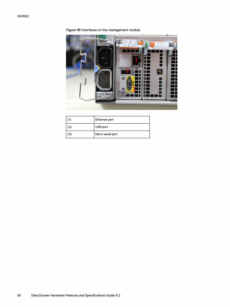
Figure 46 Interfaces on the management module
(1) Ethernet port
(2) USB port
(3) Micro serial port
DD4500
80 Data Domain Hardware Features and Specifications Guide 6.2
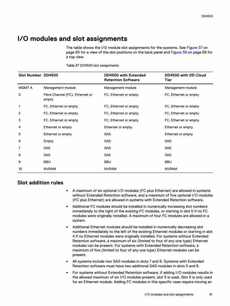
I/O modules and slot assignmentsThe table shows the I/O module slot assignments for the systems. See Figure 37 onpage 65 for a view of the slot positions on the back panel and Figure 39 on page 69 fora top view.
Table 37 DD4500 slot assignments
Slot Number DD4500 DD4500 with ExtendedRetention Software
DD4500 with DD CloudTier
MGMT A Management module Management module Management module
0 Fibre Channel (FC), Ethernet orempty
FC, Ethernet or empty FC, Ethernet or empty
1 FC, Ethernet or empty FC, Ethernet or empty FC, Ethernet or empty
2 FC, Ethernet or empty FC, Ethernet or empty FC, Ethernet or empty
3 FC, Ethernet or empty FC, Ethernet or empty FC, Ethernet or empty
4 Ethernet or empty Ethernet or empty Ethernet or empty
5 Ethernet or empty SAS Ethernet or empty
6 Empty SAS SAS
7 SAS SAS SAS
8 SAS SAS SAS
9 BBU BBU BBU
10 NVRAM NVRAM NVRAM
Slot addition rulesl A maximum of six optional I/O modules (FC plus Ethernet) are allowed in systems
without Extended Retention software, and a maximum of five optional I/O modules(FC plus Ethernet) are allowed in systems with Extended Retention software.
l Additional FC modules should be installed in numerically increasing slot numbersimmediately to the right of the existing FC modules, or starting in slot 0 if no FCmodules were originally installed. A maximum of four FC modules are allowed in asystem.
l Additional Ethernet modules should be installed in numerically decreasing slotnumbers immediately to the left of the existing Ethernet modules or starting in slot4 if no Ethernet modules were originally installed. For systems without ExtendedRetention software, a maximum of six (limited to four of any one type) Ethernetmodules can be present. For systems with Extended Retention software, amaximum of five (limited to four of any one type) Ethernet modules can bepresent.
l All systems include two SAS modules in slots 7 and 8. Systems with ExtendedRetention software must have two additional SAS modules in slots 5 and 6.
l For systems without Extended Retention software, if adding I/O modules results inthe allowed maximum of six I/O modules present, slot 5 is used. Slot 5 is only usedfor an Ethernet module. Adding FC modules in this specific case require moving an
DD4500
I/O modules and slot assignments 81
existing Ethernet module to slot 5. Other than this specific case, it is notrecommended to move I/O modules between slots.
l Adding Extended Retention software to a system includes adding two SASmodules in slots 5 and 6. If the system originally had the maximum of 6 optionalI/O modules, the I/O module in slot 5 must be permanently removed from thesystem.
Fibre Channel (FC) I/O Module OptionAn FC I/O module is a dual-port Fibre Channel module. The optional virtual tape library(VTL) feature requires at least one FC I/O module. Boost over Fiber Channel isoptional and the total FC HBAs cannot exceed more than allowable Fibre Channelcards per controller.
Ethernet I/O Module OptionsThe available Ethernet I/O modules are:
l Dual Port 10GBase-SR Optical with LC connectors
l Dual Port 10GBase-CX1 Direct Attach Copper with SPF+ module
l Quad Port 1000Base-T Copper with RJ-45 connectors
l Quad port 2 port 1000Base-T Copper (RJ45) /2 port 1000Base-SR Optical
DD4500
82 Data Domain Hardware Features and Specifications Guide 6.2

Internal system componentsThe photo shows the system with the system processor (SP) module that is removedfrom the chassis and the SP cover removed.
Figure 47 Top view of SP module with SP cover removed
(1) Front of system
(2) Four groups of 4 DIMM cards
DIMM modulesDD4500 systems contain 8 x 8 GB and 8 x 16 GB of memory DIMM. DIMMs must be inspecific slots based on DIMM size.
DD4500
Internal system components 83

DD4500
84 Data Domain Hardware Features and Specifications Guide 6.2

CHAPTER 6
DD6300
l DD6300 system features................................................................................... 86l DD6300 system specifications........................................................................... 87l DD6300 storage capacity...................................................................................87l DD6300 front panel............................................................................................88l Back panel.......................................................................................................... 91l I/O modules....................................................................................................... 94l Internal system components.............................................................................. 97
DD6300 85

DD6300 system features
Table 38 DD6300 system features
Feature DD6300 (Baseconfiguration)
DD6300(Expandedconfiguration)
Rack height 2U 2U
Processor E5-2620 V3 E5-2620 V3
Kernel 3.2.x 3.2.x
NVRAM NVRAM 8g Model3
NVRAM 8g Model3
Memory 6 x 8 GB DIMM (48GB)
12 x 8 GB DIMM(96 GB)
Internal drives HDDs in 3.5" bays 7/ 7+5 12
SSDs in 3.5" bays 0 0
SSDs in 2.5" bays 1 2
I/O module slots SAS I/O modules (Quad Port6 Gbps SAS)
l 0 for internalstorage only
l 1 with externalstorage
l 0 for internalstorage only
l 1 with externalstorage
Network and FC I/O modules Four replaceableI/O module slots.Not hot-swappable.
Four replaceableI/O module slots.Not hot-swappable.
Supported capacity 76 TB (28 TBinternal + 48 TBexternal)
180 TB (36 TBinternal + 144 TBexternal)
High availability support No No
HA private interconnect N/A N/A
External SSD shelf N/A N/A
SAS string depth(max)
ES30 1 4
DS60 0 1
Stream count 270 writes, 75reads
270 writes, 75reads
DD6300
86 Data Domain Hardware Features and Specifications Guide 6.2

DD6300 system specifications
Table 39 DD6300 system specifications
Model Averagepowerconsumption25 C
Heat dissipation(operatingmaximum)
Weight a Width Depth Height
DD6300 530W 1.69 x 10⁶ J/hr (1604Btu/hr) maximum
80 lbs (36.29kg)
17.50 in (44.45cm)
30.5 in (77.5 cm) 3.40 in (8.64cm)
a. The weight does not include mounting rails. Allow 2.3-4.5 kg (5-10 lb) for a rail set.
Table 40 System operating environment
Requirement Description
Ambient temperature 10°C - 35°C; derate 1.1°C per 1,000 ft (304m)
Relative humidity (extremes) 20–80% noncondensing
Elevation 0 - 7,500ft (0 - 2,268m)
Operating acoustic noise Lwad sound power, 7.5 Bels
DD6300 storage capacity
The following table provides storage capacity information for the DD6300 system.
Table 41 DD6300 storage capacity
Memory Internaldisks
Internalstorage(raw)
Externalstorage(raw)
Usable data storage space (TB/TiB/GB/GiB)a
48 GB(Factorybase)
l Front: 7x 4 TB
l Rear: 1x 800GB SSD
28 TB 60 TB l Internal:14 TB
l External:48 TB
l Internal:12.74 TiB
l External:43.68 TiB
l Internal:14,000 GB
l External:48,000 GB
l Internal:13,039 GiB
l External:44,704 GiB
48 GB(Factoryupgrade)
l 12 x 4TB HDD
l Rear: 1x 800GB SSD
48 TB 60 TB l Internal:34 TB
l External:48 TB
l Internal:30.94 TiB
l External:43.68 TiB
l Internal:34,000 GB
l External:48,000 GB
l Internal:31,665 GiB
l External:44,704 GiB
48 GB(FieldUpgrade)
l (7 + 5)x 4 TBHDD
48 TB 60 TB l Internal:22 TB
l Internal:20.02 TiB
l Internal:22,000 GB
l Internal:20,489 GiB
DD6300
DD6300 system specifications 87

Table 41 DD6300 storage capacity (continued)
Memory Internaldisks
Internalstorage(raw)
Externalstorage(raw)
Usable data storage space (TB/TiB/GB/GiB)a
l Rear: 1x 800GB SSD
l External:48 TB
l External:43.68 TiB
l External:48,000 GB
l External:44,704 GiB
96 GB(Expanded)
l Front:12 x 4TBHDDs
l Rear: 2x 800GB SSD
48 TB 180 TB l Internal:34 TB
l External:144 TB
l Internal:30.94 TiB
l External:131 TiB
l Internal:34,000 GB
l External:144,000 GB
l Internal:31,665 GiB
l External:134,110 GiB
96 GB(Fieldupgradefrom 48GB)
l Front:(7 + 5)x 4 TBHDDs
l Rear: 2x 800GB SSD
48 TB 180 TB l Internal:22 TB
l External:144 TB
l Internal:20.02 TiB
l External:131 TiB
l Internal:22,000 GB
l External:144,000 GB
l Internal:20,489 GiB
l External:134,110 GiB
a. The capacity differs depending on the size of the external storage shelves used. This data based on ES30 shelves.
DD6300 front panel
DD6300 All-in-One (AIO) systems have one of the following front panel driveconfigurations to host the DD OS boot drives, and provide storage for customer data:
Note
Upgrading a base configuration to an expanded configuration provides less capacitythan a factory-built expanded configuration.
Table 42 DD6300 AIO capacity
Configuration Installed drives Usable internalcapacity
DD6300 baseconfiguration
Seven 4 TB HDDs 14 TB
DD6300 expandedconfiguration (factory)
Twelve 4 TB HDDs 34 TB
DD6300 expandedconfiguration (upgrade)
Seven 4 TB HDDs + Five 4 TB HDDs 22 TB
DD6300
88 Data Domain Hardware Features and Specifications Guide 6.2

Table 43 DD6300 AIO configuration
Slot 0: HDD 1 Slot 1: HDD 2 Slot 2: HDD 3 Slot 3: HDD 4
Slot 4: HDD 5 Slot 5: HDD 6 Slot 6: HDD 7 Slot 7: Filler
Slot 8: Filler Slot 9: Filler Slot 10: Filler Slot 11: Filler
Table 44 DD6300 AIO expanded configuration
Slot 0: HDD 1 Slot 1: HDD 2 Slot 2: HDD 3 Slot 3: HDD 4
Slot 4: HDD 5 Slot 5: HDD 6 Slot 6: HDD 7 Slot 7: HDD 8
Slot 8: HDD 9 Slot 9: HDD 10 Slot 10: HDD 11 Slot 11: HDD 12
Front LED indicatorsThe front of the system contain 12 disk drive status LEDs that are normally blue, andblink when there is activity on the disk. The LEDs are shaped like triangles, and theapex of the triangle points left or right, indicating that disk's status. If the disk drivehas a failure, the disk’s status LED turns from blue to amber, indicating that a drivemust be replaced.
The front also contains two system status LEDs. A blue system power LED is presentthat is on whenever the system has power. An amber system fault LED is also presentthat is normally off and lit amber whenever the chassis or any other FRU in the systemrequires service.
Figure 48 Front LED indicators
1. System service LED2. Drive activity/service LED3. System power LED
Table 45 Front LEDs
Name Color Purpose
System power LED Blue Indication that the system haspower.
System service LED Amber Normally off; is lit amberwhenever the SP or any otherFRU (except disk drives) inthe system requires service.
DD6300
Front LED indicators 89

Table 45 Front LEDs (continued)
Name Color Purpose
Drive activity/Service LED Blue /Amber l Lit blue when the drive ispowered.
l Blinks blue during driveactivity.
l Lit solid amber when adisk needs service.
DD6300
90 Data Domain Hardware Features and Specifications Guide 6.2

Back panelThe back panel of the chassis contains the following components:
1. Management panel
2. Two 2.5" SSD slots labeled 0 and 1
3. I/O module slots
4. Power supply modules (PSU 0 is the lower module, and PSU 1 is the uppermodule)
DD6300 rear SSDsThe D6300 system uses one or two 800 GB SSDs mounted at the rear of the chassisfor metadata caching:
Configuration Number of SSDs SSD location
DD6300 1 SSD slot 0
DD6300 expanded 2 SSD slots 0 and 1
Note
SSDs are not RAID-protected.
Rear LED indicatorsFigure 49 Rear LED indicators
1. Do not remove LED2. SP service LED3. System power LED4. AC power good LED5. DC power good LED
DD6300
Back panel 91

Figure 49 Rear LED indicators (continued)
6. Power supply fault LED
Name of LED Location Color Definition
"Do not remove" LED Upper left-most partof rear chassis
White This LED is lit duringsystem BIOS andBMC firmwareupdates and indicatesthat the SP shouldnot be removed fromthe chassis, norshould system powerbe removed.
SP service LED To the right of "Donot remove" LED
Amber l Solid amber - SPor a FRU insidethe SP requiresservice
l Blinking amber -blink rate reflectsone of thefollowing isbooting
n BIOS - 1/4 Hz
n POST - 1 Hz
n OS - 4 Hz
Drive Power/ActivityLED a
Left LED on the SSD Blue Lit blue when thedrive is powered.Blinks during driveactivity.
Drive Fault LED a Right LED on the SSD Amber Lit solid amber when adrive needs service.
System power LED Right-most LED onthe managementpanel
Blue SP has good, stablepower
PSU FRU LED - ACGood
Top LED on powersupply
Green AC input is asexpected
PSU FRU LED - DCGood
Middle LED on powersupply
Green DC output is asexpected
PSU FRU LED -Attention
Bottom LED on powersupply
Amber PSU has encountereda fault condition
a. The SSD is only present on DD6300 systems.
DD6300
92 Data Domain Hardware Features and Specifications Guide 6.2

Figure 50 I/O module Power/Service LED location
1. I/O module power/service LED
Name of LED Location Color Definition
I/O module FRU LED- Figure 50 on page93
Ejector handle of I/Omodules
Green/Amber l Green - I/Omodule has powerand is functioningnormally
l Amber - I/Omodule hasencountered afault conditionand requiresservice
I/O port status LED(SAS, Fibre Channel,and opticalnetworking I/Omodules only)
One LED per I/Omodule port
Blue Lit when port isenabled. May flash ifSW "marks" theport. a
a. For RJ45 networking ports, the standard green link and amber activity LEDs are used.
DD6300
Rear LED indicators 93

Figure 51 Onboard network port LEDs
1. Network port link LED2. Network port activity LED3. Dedicated IPMI port BMC0A4. Management interface EthMa
Name of LED Location Color Definition
Onboard network portLED - Link LED Figure51 on page 94
Top LED on networkport
Green l Lit when there isa link at1000BaseT and100BaseT speeds
l Off when the linkspeed is 10BaseTor there is no link
Onboard network portLED - Activity LED
Bottom LED onnetwork port
Amber Blinks when there istraffic on the port
I/O modulesI/O module slot numberingThe eight I/O module slots are enumerated as Slot 0 (on the left when viewed fromthe rear) through Slot 7. Ports on an I/O module are enumerated as 0 through 3, with0 being on the bottom.
Figure 52 I/O module slot numbering
1. Slot 02. Slot 13. Slot 24. Slot 35. Slot 46. Slot 5
DD6300
94 Data Domain Hardware Features and Specifications Guide 6.2
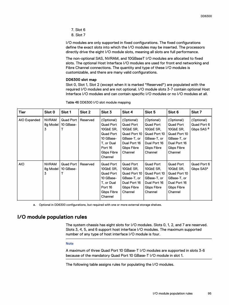
7. Slot 68. Slot 7
I/O modules are only supported in fixed configurations. The fixed configurationsdefine the exact slots into which the I/O modules may be inserted. The processorsdirectly drive the eight I/O module slots, meaning all slots are full performance.
The non-optional SAS, NVRAM, and 10GBaseT I/O modules are allocated to fixedslots. The optional Host Interface I/O modules are used for front end networking andFibre Channel connections. The quantity and type of these I/O modules iscustomizable, and there are many valid configurations.
DD6300 slot mapSlot 0, Slot 1, Slot 2 (except when it is marked "Reserved") are populated with therequired I/O modules and are not optional. I/O module slots 3-7 contain optional HostInterface I/O modules and can contain specific I/O modules or no I/O modules at all.
Table 46 DD6300 I/O slot module mapping
Tier Slot 0 Slot 1 Slot 2 Slot 3 Slot 4 Slot 5 Slot 6 Slot 7
AIO Expanded NVRAM8g Model3
Quad Port10 GBase-T
Reserved (Optional)Quad Port10GbE SR,Quad Port10 GBase-T, or DualPort 16Gbps FibreChannel
(Optional)Quad Port10GbE SR,Quad Port 10GBase-T, orDual Port 16Gbps FibreChannel
(Optional)Quad Port10GbE SR,Quad Port 10GBase-T, orDual Port 16Gbps FibreChannel
(Optional)Quad Port10GbE SR,Quad Port 10GBase-T, orDual Port 16Gbps FibreChannel
(Optional)Quad Port 6Gbps SAS a
AIO NVRAM8g Model3
Quad Port10 GBase-T
Reserved Quad Port10GbE SR,Quad Port10 GBase-T, or DualPort 16Gbps FibreChannel
Quad Port10GbE SR,Quad Port 10GBase-T, orDual Port 16Gbps FibreChannel
Quad Port10GbE SR,Quad Port 10GBase-T, orDual Port 16Gbps FibreChannel
Quad Port10GbE SR,Quad Port 10GBase-T, orDual Port 16Gbps FibreChannel
Quad Port 6Gbps SASa
a. Optional in DD6300 configurations, but required with one or more external storage shelves.
I/O module population rulesThe system chassis has eight slots for I/O modules. Slots 0, 1, 2, and 7 are reserved.Slots 3, 4, 5, and 6 support host interface I/O modules. The maximum supportednumber of any type of host interface I/O module is four.
Note
A maximum of three Quad Port 10 GBase-T I/O modules are supported in slots 3-6because of the mandatory Quad Port 10 GBase-T I/O module in slot 1.
The following table assigns rules for populating the I/O modules.
DD6300
I/O module population rules 95

Table 47 I/O module slot population rules
Step I/O module name Slots Notes
Step 1: Populatemandatory I/Omodules
NVRAM 8g Model 3 0 Mandatory for allconfigurations
Quad Port 10 GBase-T
1 Mandatory for allconfigurations
Quad Port 6 GbpsSAS
2 Reserved for DD6300expandedconfiguration.
Quad Port 6 GbpsSAS
7 Reserved for DD6300for baseconfiguration.
Step 2: Populate allQuad Port 10GbE SRI/O modules
Quad Port 10GbE SR 3, 4, 5, 6 Populate startingfrom the lowestavailable slot number.
Step 3: Populate allQuad Port 10 GBase-T I/O modules
Quad Port 10 GBase-T
3, 4, 5, 6 Populate startingfrom the lowestavailable slot number.With Quad Port 10GBase-T in slot 1, maxnumber of Quad Port10 GBase-T I/Omodules are limited to4.
Step 4: Populate allDual Port 16 GbpsFibre Channel I/Omodules
Dual Port 16 GbpsFibre Channel
6, 5, 4, 3 Populate startingfrom the highestavailable slot number.
DD6300
96 Data Domain Hardware Features and Specifications Guide 6.2

Internal system componentsThe following figure shows the layout of the CPUs and DIMMs inside the chassis. Thefront of the system is at the top of the figure.
Figure 53 CPU and memory locations
DIMMs overviewDual in-line memory modules (DIMM) come in various sizes, which must be configuredin a certain way. This topic can help you select the correct configuration whenservicing DIMMs.
The storage processor contains two Intel processors each with an integrated memorycontroller that supports four channels of memory. The storage processor allows twoDIMM slots per channel, so the storage processor supports a total of 16 DIMM slots.
DD6300 memory DIMM configuration
Table 48 DD6300 memory DIMM configuration
Tier Total Memory Memory DIMM Configuration
DD6300 AIO Expanded 96 GB 12 x 8 GB
DD6300 AIO 48 GB 6 x 8 GB
To ensure maximum memory performance, there are memory DIMM population rulesfor best memory loading and interleaving. Table 49 on page 97 and Table 50 onpage 98 specify the DIMM location rules for various memory configurations:
Table 49 Memory locations - CPU 0
Channel A Channel B Channel D Channel C
Tier TotalMemory
0 1 2 3 4 5 6 7
DD6300 AIOExpanded
96 GB 8 GB N/A 8 GB N/A 8 GB 8 GB 8 GB 8 GB
DD6300 AIO 48 GB N/A N/A 8 GB N/A N/A 8 GB N/A 8 GB
DD6300
Internal system components 97

Table 50 Memory locations - CPU 1
Channel A Channel B Channel D Channel C
Tier TotalMemory
8 9 10 11 12 13 14 15
DD6300 AIOExpanded
96 GB 8 GB 8 GB 8 GB 8 GB N/A 8 GB N/A 8 GB
DD6300 AIO 48 GB 8 GB N/A 8 GB N/A N/A 8 GB N/A N/A
DD6300
98 Data Domain Hardware Features and Specifications Guide 6.2
CHAPTER 7
DD6800
l DD6800 system features.................................................................................. 100l DD6800 system specifications.......................................................................... 101l DD6800 storage capacity..................................................................................101l DD6800 front panel.......................................................................................... 102l Back panel........................................................................................................ 104l I/O modules...................................................................................................... 107l Internal system components............................................................................. 110
DD6800 99

DD6800 system features
Table 51 DD6800 system features
Feature DD6800 (Baseconfiguration)
DD6800(Expandedconfiguration)
Rack height 2U 2U
Processor E5-2630 V3 E5-2630 V3
Kernel 3.2.x 3.2.x
NVRAM NVRAM 8g Model3
NVRAM 8g Model3
Memory 8 x 8 GB DIMM + 8x 16 GB DIMM (192GB)
8 x 8 GB DIMM + 8x 16 GB DIMM (192GB)
Internal drives HDDs in 3.5" bays 7/ 7+5 12
SSDs in 3.5" bays 0 0
SSDs in 2.5" bays 1 2
I/O module slots SAS I/O modules (Quad Port6 Gbps SAS)
2 2
Network and FC I/O modules Four replaceableI/O module slots.Not hot-swappable.
Four replaceableI/O module slots.Not hot-swappable.
Supported capacity Non-extended retention 144 TB 288 TB
DD Cloud Tier N/A 576 TB a
Extended retention N/A 288 TBb
High availability support Yes Yes
HA private interconnect (2) 10GBase-Tports
(2) 10GBase-Tports
External SSD shelf One SSD shelf forA-P highavailability clustercontaining twodrives.
One SSD shelf forA-P highavailability clustercontaining fourdrives.
SAS string depth(max)
ES30 1 4
DS60 0 1
ES30 and DS60 5 shelves total 5 shelves total
Stream count 405 writes, 112reads
405 writes, 112reads
DD6800
100 Data Domain Hardware Features and Specifications Guide 6.2
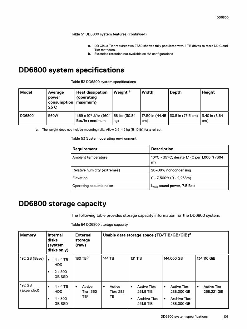
Table 51 DD6800 system features (continued)
a. DD Cloud Tier requires two ES30 shelves fully populated with 4 TB drives to store DD CloudTier metadata.
b. Extended retention not available on HA configurations
DD6800 system specifications
Table 52 DD6800 system specifications
Model Averagepowerconsumption25 C
Heat dissipation(operatingmaximum)
Weight a Width Depth Height
DD6800 560W 1.69 x 10⁶ J/hr (1604Btu/hr) maximum
68 lbs (30.84kg)
17.50 in (44.45cm)
30.5 in (77.5 cm) 3.40 in (8.64cm)
a. The weight does not include mounting rails. Allow 2.3-4.5 kg (5-10 lb) for a rail set.
Table 53 System operating environment
Requirement Description
Ambient temperature 10°C - 35°C; derate 1.1°C per 1,000 ft (304m)
Relative humidity (extremes) 20–80% noncondensing
Elevation 0 - 7,500ft (0 - 2,268m)
Operating acoustic noise Lwad sound power, 7.5 Bels
DD6800 storage capacity
The following table provides storage capacity information for the DD6800 system.
Table 54 DD6800 storage capacity
Memory Internaldisks(systemdisks only)
Externalstorage(raw)
Usable data storage space (TB/TiB/GB/GiB)a
192 GB (Base) l 4 x 4 TBHDD
l 2 x 800GB SSD
180 TBb 144 TB 131 TiB 144,000 GB 134,110 GiB
192 GB(Expanded)
l 4 x 4 TBHDD
l 4 x 800GB SSD
l ActiveTier: 360TBb
l ActiveTier: 288TB
l Active Tier:261.9 TiB
l Archive Tier:261.9 TiB
l Active Tier:288,000 GB
l Archive Tier:288,000 GB
l Active Tier:268,221 GiB
DD6800
DD6800 system specifications 101

Table 54 DD6800 storage capacity (continued)
Memory Internaldisks(systemdisks only)
Externalstorage(raw)
Usable data storage space (TB/TiB/GB/GiB)a
l ArchiveTier: 360TBc
l Cloud Tier:720 TB inthe cloudd
l Cloud Tiermetadata:120 TBlocalstorage
l ArchiveTier: 288TB
l Cloud Tier:576 TB
l Cloud Tiermetadata:96 TB
l Cloud Tier:523.8 TiB
l Cloud Tiermetadata:87.3 TiB
l Cloud Tier:576,000 GB
l Cloud Tiermetadata:96,000 GB
l Archive Tier:268,221 GiB
l Cloud Tier:536,442 GiB
l Cloud Tiermetadata:89,407 GiB
a. The capacity differs depending on the size of the external storage shelves used. This data based on ES30 shelves.b. HA is supported.c. HA is not supported with Extended Retention.d. HA is supported in combination with Cloud Tier.
DD6800 front panel
DD6800 Dataless Head (DLH) systems have one of the following front panel driveconfigurations to host the DD OS boot drives and provide metadata caching on SSD:
Table 55 DD6800 DLH SSD requirements
Configuration Number of SSDs
DD6800 2
DD6800 expanded 4
Note
SSDs are not RAID-protected.
Table 56 DD6800 DLH configuration drive layout
Slot 0: HDD 1 Slot 1: HDD 2 Slot 2: HDD 3 Slot 3: HDD 4
Slot 4: SSD 1 Slot 5: SSD 2 Slot 6: Filler Slot 7: Filler
Slot 8: Filler Slot 9: Filler Slot 10: Filler Slot 11: Filler
Table 57 DD6800 DLH expanded configuration drive layout
Slot 0: HDD 1 Slot 1: HDD 2 Slot 2: HDD 3 Slot 3: HDD 4
Slot 4: SSD 1 Slot 5: SSD 2 Slot 6: SSD 3 Slot 7: SSD 4
DD6800
102 Data Domain Hardware Features and Specifications Guide 6.2

Table 57 DD6800 DLH expanded configuration drive layout (continued)
Slot 8: Filler Slot 9: Filler Slot 10: Filler Slot 11: Filler
Front LED indicatorsThe front of the system contain 12 disk drive status LEDs that are normally blue, andblink when there is activity on the disk. The LEDs are shaped like triangles, and theapex of the triangle points left or right, indicating that disk's status. If the disk drivehas a failure, the disk’s status LED turns from blue to amber, indicating that a drivemust be replaced.
The front also contains two system status LEDs. A blue system power LED is presentthat is on whenever the system has power. An amber system fault LED is also presentthat is normally off and lit amber whenever the chassis or any other FRU in the systemrequires service.
Figure 54 Front LED indicators
1. System service LED2. Drive activity/service LED3. System power LED
Table 58 Front LEDs
Name Color Purpose
System power LED Blue Indication that the system haspower.
System service LED Amber Normally off; is lit amberwhenever the SP or any otherFRU (except disk drives) inthe system requires service.
Drive activity/Service LED Blue /Amber l Lit blue when the drive ispowered.
l Blinks blue during driveactivity.
l Lit solid amber when adisk needs service.
DD6800
Front LED indicators 103

Back panelThe back panel of the chassis contains the following components:
1. Management panel
2. Not Used -- Two 2.5" SSD slots labeled 0 and 1
3. I/O module slots
4. Power supply modules (PSU 0 is the lower module, and PSU 1 is the uppermodule)
Rear LED indicatorsFigure 55 Rear LED indicators
1. Do not remove LED2. SP service LED3. System power LED4. AC power good LED5. DC power good LED6. Power supply fault LED
Name of LED Location Color Definition
"Do not remove" LED Upper left-most partof rear chassis
White This LED is lit duringsystem BIOS andBMC firmwareupdates and indicatesthat the SP shouldnot be removed fromthe chassis, norshould system powerbe removed.
DD6800
104 Data Domain Hardware Features and Specifications Guide 6.2
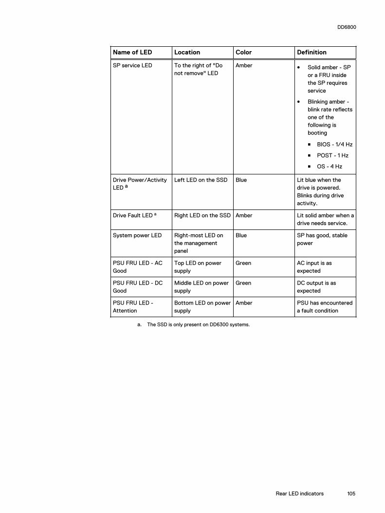
Name of LED Location Color Definition
SP service LED To the right of "Donot remove" LED
Amber l Solid amber - SPor a FRU insidethe SP requiresservice
l Blinking amber -blink rate reflectsone of thefollowing isbooting
n BIOS - 1/4 Hz
n POST - 1 Hz
n OS - 4 Hz
Drive Power/ActivityLED a
Left LED on the SSD Blue Lit blue when thedrive is powered.Blinks during driveactivity.
Drive Fault LED a Right LED on the SSD Amber Lit solid amber when adrive needs service.
System power LED Right-most LED onthe managementpanel
Blue SP has good, stablepower
PSU FRU LED - ACGood
Top LED on powersupply
Green AC input is asexpected
PSU FRU LED - DCGood
Middle LED on powersupply
Green DC output is asexpected
PSU FRU LED -Attention
Bottom LED on powersupply
Amber PSU has encountereda fault condition
a. The SSD is only present on DD6300 systems.
DD6800
Rear LED indicators 105

Figure 56 I/O module Power/Service LED location
1. I/O module power/service LED
Name of LED Location Color Definition
I/O module FRU LED- Figure 56 on page106
Ejector handle of I/Omodules
Green/Amber l Green - I/Omodule has powerand is functioningnormally
l Amber - I/Omodule hasencountered afault conditionand requiresservice
I/O port status LED(SAS, Fibre Channel,and opticalnetworking I/Omodules only)
One LED per I/Omodule port
Blue Lit when port isenabled. May flash ifSW "marks" theport. a
a. For RJ45 networking ports, the standard green link and amber activity LEDs are used.
DD6800
106 Data Domain Hardware Features and Specifications Guide 6.2

Figure 57 Onboard network port LEDs
1. Network port link LED2. Network port activity LED3. Dedicated IPMI port BMC0A4. Management interface EthMa
Name of LED Location Color Definition
Onboard network portLED - Link LED Figure57 on page 107
Top LED on networkport
Green l Lit when there isa link at1000BaseT and100BaseT speeds
l Off when the linkspeed is 10BaseTor there is no link
Onboard network portLED - Activity LED
Bottom LED onnetwork port
Amber Blinks when there istraffic on the port
I/O modulesI/O module slot numberingThe eight I/O module slots are enumerated as Slot 0 (on the left when viewed fromthe rear) through Slot 7. Ports on an I/O module are enumerated as 0 through 3, with0 being on the bottom.
Figure 58 I/O module slot numbering
1. Slot 02. Slot 13. Slot 24. Slot 35. Slot 46. Slot 5
DD6800
I/O modules 107
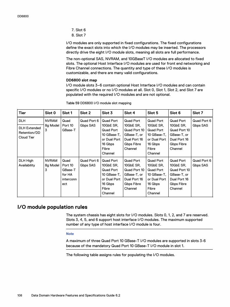
7. Slot 68. Slot 7
I/O modules are only supported in fixed configurations. The fixed configurationsdefine the exact slots into which the I/O modules may be inserted. The processorsdirectly drive the eight I/O module slots, meaning all slots are full performance.
The non-optional SAS, NVRAM, and 10GBaseT I/O modules are allocated to fixedslots. The optional Host Interface I/O modules are used for front end networking andFibre Channel connections. The quantity and type of these I/O modules iscustomizable, and there are many valid configurations.
DD6800 slot mapI/O module slots 3–6 contain optional Host Interface I/O modules and can containspecific I/O modules or no I/O modules at all. Slot 0, Slot 1, Slot 2, and Slot 7 arepopulated with the required I/O modules and are not optional.
Table 59 DD6800 I/O module slot mapping
Tier Slot 0 Slot 1 Slot 2 Slot 3 Slot 4 Slot 5 Slot 6 Slot 7
DLH NVRAM8g Model3
QuadPort 10GBase-T
Quad Port 6Gbps SAS
Quad Port10GbE SR,Quad Port10 GBase-T,or Dual Port16 GbpsFibreChannel
Quad Port10GbE SR,Quad Port 10GBase-T, orDual Port 16Gbps FibreChannel
Quad Port10GbE SR,Quad Port10 GBase-T,or Dual Port16 GbpsFibreChannel
Quad Port10GbE SR,Quad Port 10GBase-T, orDual Port 16Gbps FibreChannel
Quad Port 6Gbps SAS
DLH ExtendedRetention/DDCloud Tier
DLH HighAvailability
NVRAM8g Model3
QuadPort 10GBase-Tfor HAinterconnect
Quad Port 6Gbps SAS
Quad Port10GbE SR,Quad Port10 GBase-T,or Dual Port16 GbpsFibreChannel
Quad Port10GbE SR,Quad Port 10GBase-T, orDual Port 16Gbps FibreChannel
Quad Port10GbE SR,Quad Port10 GBase-T,or Dual Port16 GbpsFibreChannel
Quad Port10GbE SR,Quad Port 10GBase-T, orDual Port 16Gbps FibreChannel
Quad Port 6Gbps SAS
I/O module population rulesThe system chassis has eight slots for I/O modules. Slots 0, 1, 2, and 7 are reserved.Slots 3, 4, 5, and 6 support host interface I/O modules. The maximum supportednumber of any type of host interface I/O module is four.
Note
A maximum of three Quad Port 10 GBase-T I/O modules are supported in slots 3-6because of the mandatory Quad Port 10 GBase-T I/O module in slot 1.
The following table assigns rules for populating the I/O modules.
DD6800
108 Data Domain Hardware Features and Specifications Guide 6.2
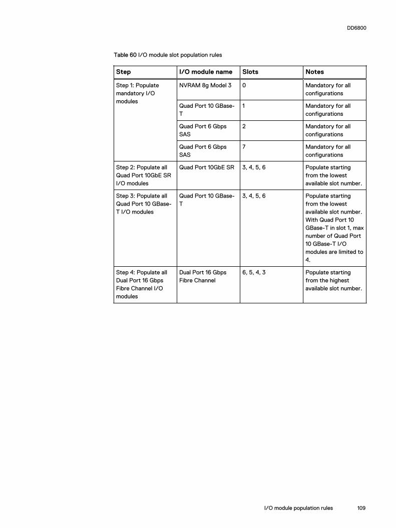
Table 60 I/O module slot population rules
Step I/O module name Slots Notes
Step 1: Populatemandatory I/Omodules
NVRAM 8g Model 3 0 Mandatory for allconfigurations
Quad Port 10 GBase-T
1 Mandatory for allconfigurations
Quad Port 6 GbpsSAS
2 Mandatory for allconfigurations
Quad Port 6 GbpsSAS
7 Mandatory for allconfigurations
Step 2: Populate allQuad Port 10GbE SRI/O modules
Quad Port 10GbE SR 3, 4, 5, 6 Populate startingfrom the lowestavailable slot number.
Step 3: Populate allQuad Port 10 GBase-T I/O modules
Quad Port 10 GBase-T
3, 4, 5, 6 Populate startingfrom the lowestavailable slot number.With Quad Port 10GBase-T in slot 1, maxnumber of Quad Port10 GBase-T I/Omodules are limited to4.
Step 4: Populate allDual Port 16 GbpsFibre Channel I/Omodules
Dual Port 16 GbpsFibre Channel
6, 5, 4, 3 Populate startingfrom the highestavailable slot number.
DD6800
I/O module population rules 109

Internal system componentsThe following figure shows the layout of the CPUs and DIMMs inside the chassis. Thefront of the system is at the top of the figure.
Figure 59 CPU and memory locations
DIMMs overviewDual in-line memory modules (DIMM) come in various sizes, which must be configuredin a certain way. This topic can help you select the correct configuration whenservicing DIMMs.
The storage processor contains two Intel processors each with an integrated memorycontroller that supports four channels of memory. The storage processor allows twoDIMM slots per channel, so the storage processor supports a total of 16 DIMM slots.
DD6800 memory DIMM configuration
Table 61 DD6800 memory DIMM configuration
Tier Total Memory Memory DIMM Configuration
DD6800 DLH 192 GB 8 x 16 GB +8 x 8 GB
DD6800 DLH ExtendedRetention/DD Cloud Tier
192 GB 8 x 16 GB +8 x 8 GB
HA is supported with all available memory configurations.
To ensure maximum memory performance, there are memory DIMM population rulesfor best memory loading and interleaving. Table 62 on page 110 and Table 63 onpage 111 specify the DIMM location rules for various memory configurations:
Table 62 Memory locations - CPU 0
Channel A Channel B Channel D Channel C
Tier TotalMemory
0 1 2 3 4 5 6 7
DD6800 DLH(Base)
192 GB 16 GB 8 GB 16 GB 8 GB 8 GB 16 GB 8 GB 16 GB
DD6800
110 Data Domain Hardware Features and Specifications Guide 6.2
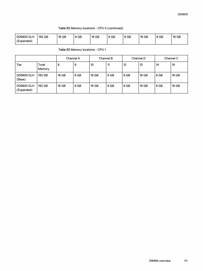
Table 62 Memory locations - CPU 0 (continued)
DD6800 DLH(Expanded)
192 GB 16 GB 8 GB 16 GB 8 GB 8 GB 16 GB 8 GB 16 GB
Table 63 Memory locations - CPU 1
Channel A Channel B Channel D Channel C
Tier TotalMemory
8 9 10 11 12 13 14 15
DD6800 DLH(Base)
192 GB 16 GB 8 GB 16 GB 8 GB 8 GB 16 GB 8 GB 16 GB
DD6800 DLH(Expanded)
192 GB 16 GB 8 GB 16 GB 8 GB 8 GB 16 GB 8 GB 16 GB
DD6800
DIMMs overview 111

DD6800
112 Data Domain Hardware Features and Specifications Guide 6.2
CHAPTER 8
DD7200
l DD7200 system features................................................................................... 114l DD7200 system specifications.......................................................................... 115l DD7200 storage capacity.................................................................................. 116l Front Panel........................................................................................................117l Back Panel........................................................................................................ 121l I/O modules and slot assignments.................................................................... 123l Internal system components.............................................................................125
DD7200 113
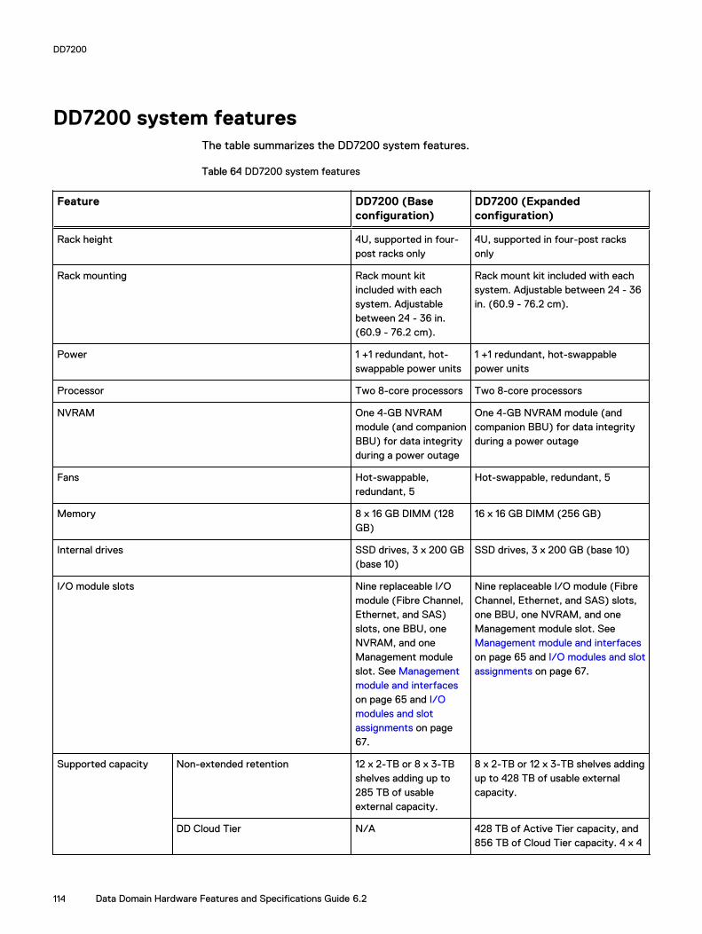
DD7200 system featuresThe table summarizes the DD7200 system features.
Table 64 DD7200 system features
Feature DD7200 (Baseconfiguration)
DD7200 (Expandedconfiguration)
Rack height 4U, supported in four-post racks only
4U, supported in four-post racksonly
Rack mounting Rack mount kitincluded with eachsystem. Adjustablebetween 24 - 36 in.(60.9 - 76.2 cm).
Rack mount kit included with eachsystem. Adjustable between 24 - 36in. (60.9 - 76.2 cm).
Power 1 +1 redundant, hot-swappable power units
1 +1 redundant, hot-swappablepower units
Processor Two 8-core processors Two 8-core processors
NVRAM One 4-GB NVRAMmodule (and companionBBU) for data integrityduring a power outage
One 4-GB NVRAM module (andcompanion BBU) for data integrityduring a power outage
Fans Hot-swappable,redundant, 5
Hot-swappable, redundant, 5
Memory 8 x 16 GB DIMM (128GB)
16 x 16 GB DIMM (256 GB)
Internal drives SSD drives, 3 x 200 GB(base 10)
SSD drives, 3 x 200 GB (base 10)
I/O module slots Nine replaceable I/Omodule (Fibre Channel,Ethernet, and SAS)slots, one BBU, oneNVRAM, and oneManagement moduleslot. See Managementmodule and interfaceson page 65 and I/Omodules and slotassignments on page67.
Nine replaceable I/O module (FibreChannel, Ethernet, and SAS) slots,one BBU, one NVRAM, and oneManagement module slot. See Management module and interfaceson page 65 and I/O modules and slotassignments on page 67.
Supported capacity Non-extended retention 12 x 2-TB or 8 x 3-TBshelves adding up to285 TB of usableexternal capacity.
8 x 2-TB or 12 x 3-TB shelves addingup to 428 TB of usable externalcapacity.
DD Cloud Tier N/A 428 TB of Active Tier capacity, and856 TB of Cloud Tier capacity. 4 x 4
DD7200
114 Data Domain Hardware Features and Specifications Guide 6.2

Table 64 DD7200 system features (continued)
Feature DD7200 (Baseconfiguration)
DD7200 (Expandedconfiguration)
TB shelves are required to store DDCloud Tier metadata.
DD Extended Retention N/A 56 shelves adding up to a maximumof 856 GB of usable externalcapacity.
DD7200 system specifications
Table 65 DD7200 system specifications
Model Watts BTU/hr Power Weight Width Depth Height
DD7200 800 2730 800 80 lb / 36.3kg
17.5 in (44.5cm)
33 in (84 cm) 7 in (17.8 cm)
Table 66 System operating environment
Operating Temperature 50° to 95° F (10° to 35° C), derate 1.1° Cper 1000 feet, above 7500 feet up to 10,000feet
Operating Humidity 20% to 80%, non-condensing
Non-operating Temperature -40° to +149° F (-40° to +65° C)
Operating Acoustic Noise Sound power, LWAd: 7.52 bels. Soundpressure, LpAm: 56.4 dB. (Declared noiseemission per ISO 9296.)
DD7200
DD7200 system specifications 115
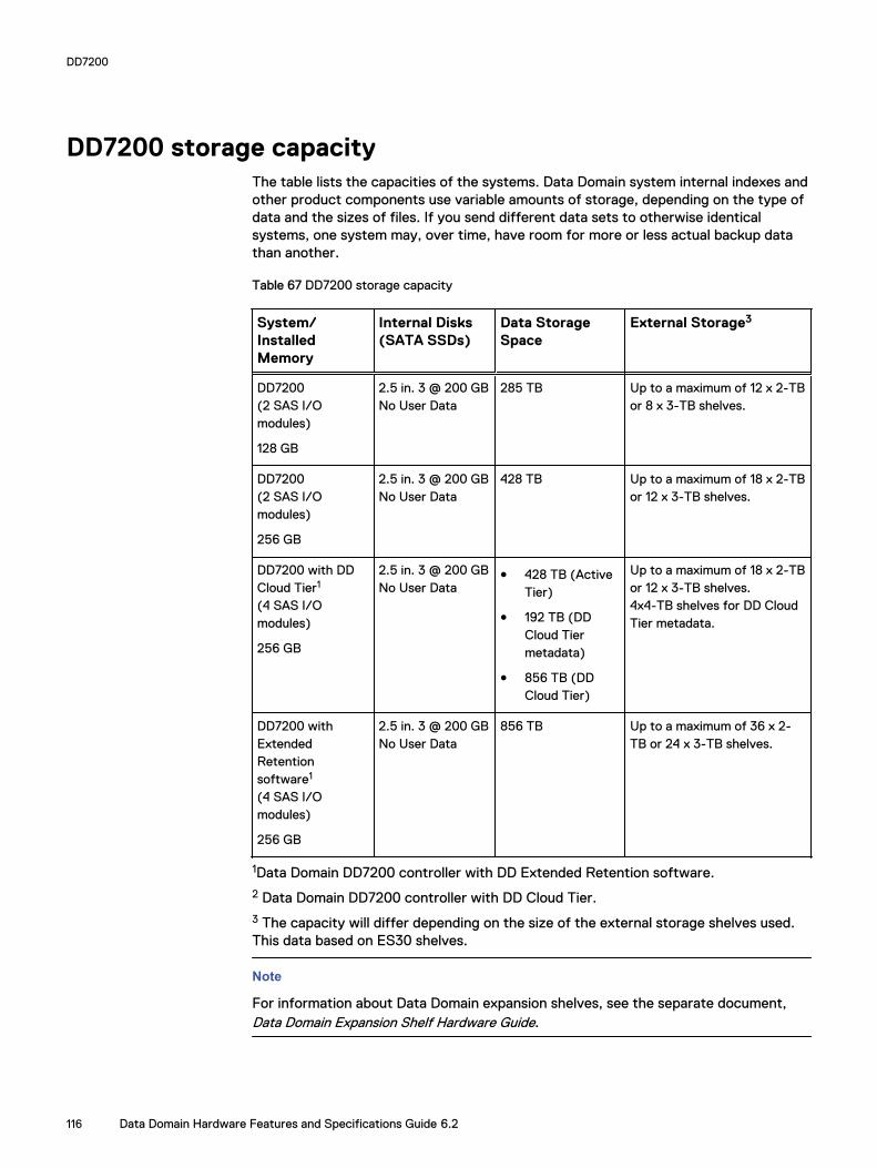
DD7200 storage capacityThe table lists the capacities of the systems. Data Domain system internal indexes andother product components use variable amounts of storage, depending on the type ofdata and the sizes of files. If you send different data sets to otherwise identicalsystems, one system may, over time, have room for more or less actual backup datathan another.
Table 67 DD7200 storage capacity
System/InstalledMemory
Internal Disks(SATA SSDs)
Data StorageSpace
External Storage3
DD7200(2 SAS I/Omodules)
128 GB
2.5 in. 3 @ 200 GBNo User Data
285 TB Up to a maximum of 12 x 2-TBor 8 x 3-TB shelves.
DD7200(2 SAS I/Omodules)
256 GB
2.5 in. 3 @ 200 GBNo User Data
428 TB Up to a maximum of 18 x 2-TBor 12 x 3-TB shelves.
DD7200 with DDCloud Tier1
(4 SAS I/Omodules)
256 GB
2.5 in. 3 @ 200 GBNo User Data
l 428 TB (ActiveTier)
l 192 TB (DDCloud Tiermetadata)
l 856 TB (DDCloud Tier)
Up to a maximum of 18 x 2-TBor 12 x 3-TB shelves.4x4-TB shelves for DD CloudTier metadata.
DD7200 withExtendedRetentionsoftware1
(4 SAS I/Omodules)
256 GB
2.5 in. 3 @ 200 GBNo User Data
856 TB Up to a maximum of 36 x 2-TB or 24 x 3-TB shelves.
1Data Domain DD7200 controller with DD Extended Retention software.2 Data Domain DD7200 controller with DD Cloud Tier.3 The capacity will differ depending on the size of the external storage shelves used.This data based on ES30 shelves.
Note
For information about Data Domain expansion shelves, see the separate document,Data Domain Expansion Shelf Hardware Guide.
DD7200
116 Data Domain Hardware Features and Specifications Guide 6.2

Front PanelThe photo shows the hardware features and interfaces on the front of the system.
Figure 60 Front panel components
(1) Filler panel
(2) The red box indicates the system processor (SP) module
(3) SSD drive #1
(4) Fan #0
(5) Power supply #B
(6) AC power disconnect plug
(7) AC power extender module
Power supply unitsA system has two power supply units, numbered A and B from the bottom up. Eachpower supply has its own integral cooling fan. Each power unit has three LEDs (see Figure 34 on page 63) that indicates the following states:
l AC LED: Glows green when AC input is good
l DC LED: Glows green when DC output is good
l Symbol “!”: Glows solid or blinking amber for fault or attention
The AC power plugs are located to the right of each power supply. These plugs arepulled to disconnect AC power to each power supply.
AC power extender moduleAC power entry is connected at the rear of the system. The AC power extendermodule provides power to the two power supplies on the front of the system. ACPower plugs are located in the front. The module is adjacent to the SP module and canbe removed and replaced.
DD7200
Front Panel 117

Cooling FansA system contains five hot-swappable cooling fans in a 4+1 redundant configuration.The fans provide cooling for the processors, DIMMs, IO modules, and the managementmodule. Each fan has a fault LED which causes the fan housing to glow amber. Asystem can run with one fan faulted or removed.
Solid-state drivesA system contains three hot-swappable 2.5" solid-state drive (SSD) bays that arelocated in the front and on top of the fan modules. There are four drive bays, with theleft-most bay containing a blank. The next drive to the right of the blank is SSD #1,the next is #2, and the right-most bay contains SSD #3. No user backup data is kepton the SSDs.
Each drive has a blue colored power LED and an amber fault LED.
Front LED IndicatorsThe photo below indicates the location of the four system LEDs.
Figure 61 System LEDs
The next photo shows the location of the system LED legend label. Figure 63 on page119 shows the power supply LEDs. Other front LEDs are shown in Figure 64 on page120. LED states are described in Table 68 on page 120.
DD7200
118 Data Domain Hardware Features and Specifications Guide 6.2

Figure 62 System LED legend label
The power supply LEDs include:
l AC LED on top
l DC LED in the middle
l Failure LED on the bottom
Figure 63 Power supply LEDs
Each SSD has two LEDs as shown in the following figure. The lower left corner of thehousing around each fan acts as an LED, glowing amber when the fan has failed.
DD7200
Front LED Indicators 119

Figure 64 Fan and SSD LEDs
Table 68 LED status indicators
Part Description or Location State
System Dot within a circle (top LED) Blue indicates power on andnormal operation.
System, SP fault Exclamation point within atriangle
Dark indicates normaloperation. Amber indicatesfailure.
System, chassis fault Exclamation point within atriangle with a light below
Dark indicates normaloperation. Yellow indicates afault condition.
System Marked out hand within ablack square (bottom LED)
White warms not to removethe unit.
Power supply AC LED Steady green indicates normalAC power.
Power supply DC LED Steady green indicates normalDC power.
Power supply Failure LED Solid amber indicates a failedpower supply.
SSD Top LED Solid blue, disk ready, blinkswhile busy.
SSD Bottom LED Dark indicates healthy. Solidamber indicates disk fail.
Fan Fan housing The fan housing glows anamber color during fan failure.
DD7200
120 Data Domain Hardware Features and Specifications Guide 6.2

Back PanelThe photo shows the hardware features and interfaces on the back of the system.
Figure 65 Features on rear of chassis
1. Upper level contains all blanks2. AC power extender module3. Management module (slot Mgmt A)4. Red box indicating I/O modules (slots 0-8)5. Battery backup (BBU in slot 9)6. NVRAM module (slot 10)7. Cage covering the BBU and NVRAM combination module8. I/O LED at the end of each I/O module handle9. Location of serial number label/tag
Note
For modules containing multiple ports, the bottom port is numbered as zero (0) withnumbers increasing going upward.
I/O module LEDsEach I/O module ejector handle contains a bi-colored LED. Green indicates normalfunction, while an amber color indicates a fault condition.
Management module and interfacesThe management module is on the left-most side when facing the back of the system,in slot Mgmt A. The process to remove and add a management module is the same asthe I/O modules, however, the management module can only be accommodated inMgmt A slot.
The management module contains one external LAN connection for managementaccess to the SP module. One micro DB-9 connector is included to provide theconsole. A USB port is provided for use during service of the system to allow bootingfrom a USB flash device.
DD7200
Back Panel 121

Figure 66 Interfaces on the management module
(1) Ethernet port
(2) USB port
(3) Micro serial port
DD7200
122 Data Domain Hardware Features and Specifications Guide 6.2

I/O modules and slot assignmentsThe table shows the I/O module slot assignments for the systems. See Figure 37 onpage 65 for a view of the slot positions on the back panel and Figure 39 on page 69 fora top view.
Table 69 DD7200 slot assignments
Slot Number DD7200 DD7200 with ExtendedRetention Software
DD7200 with DD CloudTier
MGMT A Management module Management module Management module
0 Fibre Channel (FC), Ethernet orempty
FC, Ethernet or empty FC, Ethernet or empty
1 FC, Ethernet or empty FC, Ethernet or empty FC, Ethernet or empty
2 FC, Ethernet or empty FC, Ethernet or empty FC, Ethernet or empty
3 FC, Ethernet or empty FC, Ethernet or empty FC, Ethernet or empty
4 Ethernet or empty Ethernet or empty Ethernet or empty
5 Ethernet or empty SAS SAS
6 Empty SAS SAS
7 SAS SAS SAS
8 SAS SAS SAS
9 BBU BBU BBU
10 NVRAM NVRAM NVRAM
Slot addition rulesl A maximum of six optional I/O modules (FC plus Ethernet) are allowed in systems
without Extended Retention software, and a maximum of five optional I/O modules(FC plus Ethernet) are allowed in systems with Extended Retention software.
l Additional FC modules should be installed in numerically increasing slot numbersimmediately to the right of the existing FC modules, or starting in slot 0 if no FCmodules were originally installed. A maximum of four FC modules are allowed in asystem.
l Additional Ethernet modules should be installed in numerically decreasing slotnumbers immediately to the left of the existing Ethernet modules or starting in slot4 if no Ethernet modules were originally installed. For systems without ExtendedRetention software, a maximum of six (limited to four of any one type) Ethernetmodules can be present. For systems with Extended Retention software, amaximum of five (limited to four of any one type) Ethernet modules can bepresent.
l All systems include two SAS modules in slots 7 and 8. Systems with ExtendedRetention software must have two additional SAS modules in slots 5 and 6.
l For systems without Extended Retention software, if adding I/O modules results inthe allowed maximum of six I/O modules present, slot 5 is used. Slot 5 is only usedfor an Ethernet module. Adding FC modules in this specific case require moving an
DD7200
I/O modules and slot assignments 123

existing Ethernet module to slot 5. Other than this specific case, it is notrecommended to move I/O modules between slots.
l Adding Extended Retention software to a system includes adding two SASmodules in slots 5 and 6. If the system originally had the maximum of 6 optionalI/O modules, the I/O module in slot 5 must be permanently removed from thesystem.
Fibre Channel (FC) I/O Module OptionAn FC I/O module is a dual-port Fibre Channel module. The optional virtual tape library(VTL) feature requires at least one FC I/O module. Boost over Fiber Channel isoptional and the total FC HBAs cannot exceed more than allowable Fibre Channelcards per controller.
Ethernet I/O Module OptionsThe available Ethernet I/O modules are:
l Dual Port 10GBase-SR Optical with LC connectors
l Dual Port 10GBase-CX1 Direct Attach Copper with SPF+ module
l Quad Port 1000Base-T Copper with RJ-45 connectors
l Quad port 2 port 1000Base-T Copper (RJ45) /2 port 1000Base-SR Optical
DD7200
124 Data Domain Hardware Features and Specifications Guide 6.2

Internal system componentsThe photo shows the system with the system processor (SP) module that is removedfrom the chassis and the SP cover removed.
Figure 67 Top view of SP module with SP cover removed
(1) Front of system
(2) Four groups of 4 DIMM cards
DIMM modulesl DD7200 systems with 128 GB of memory contain 8 x 16 GB DIMMs, with 8 empty
DIMM slots.
l DD7200 systems with 256 GB of memory contain 16 x 16 GB DIMMs.
DD7200
Internal system components 125

DD7200
126 Data Domain Hardware Features and Specifications Guide 6.2

CHAPTER 9
DD9300
l DD9300 system features.................................................................................. 128l DD9300 system specifications..........................................................................129l DD9300 storage capacity................................................................................. 129l DD9300 front panel.......................................................................................... 130l Back panel........................................................................................................ 132l I/O modules......................................................................................................135l Internal system components............................................................................. 138
DD9300 127

DD9300 system features
Table 70 DD9300 system features
Feature DD9300 (Baseconfiguration)
DD9300(Expandedconfiguration)
Rack height 2U 2U
Processor E5-2680 V3 E5-2680 V3
Kernel 3.2.x 3.2.x
NVRAM NVRAM 8g Model3
NVRAM 8g Model3
Memory 4 x 32 GB DIMM+ 4 x 16 GB DIMM(192 GB)
8 x 32 GB DIMM+ 8 x 16 GB DIMM(384 GB)
Internal drives HDDs in 3.5" bays 4 4
SSDs in 3.5" bays 5 8
SSDs in 2.5" bays 0 0
I/O module slots SAS I/O modules (Quad Port6 Gbps SAS)
2 2
Network and FC I/O modules Four replaceableI/O module slots.Not hot-swappable.
Four replaceableI/O module slots.Not hot-swappable.
Supported capacity Non-extended retention 384 TB 720 TB
DD Cloud Tier N/A 1440 TB a
Extended retention N/A 720 TBb
High availability support Yes Yes
HA private interconnect (2) 10GBase-Tports
(2) 10GBase-Tports
External SSD shelf One SSD shelf forA-P highavailability clustercontaining twodrives.
One SSD shelf forA-P highavailability clustercontaining fourdrives.
SAS string depth(max)
ES30 6 6 (7 for extendedretention)
DS60 3 3
ES30 and DS60 5 shelves total 5 shelves total
Stream count 810 writes, 225reads
810 writes, 225reads
DD9300
128 Data Domain Hardware Features and Specifications Guide 6.2

Table 70 DD9300 system features (continued)
a. DD Cloud Tier requires four ES30 shelves fully populated with 4 TB drives to store DD CloudTier metadata.
b. Extended retention not available on HA configurations
DD9300 system specifications
Table 71 DD9300 system specifications
Model Averagepowerconsumption25 C
Heat dissipation(operatingmaximum)
Weight a Width Depth Height
DD9300 645W 1.69 x 10⁶ J/hr (1604Btu/hr) maximum
70 lbs (31.75kg)
17.50 in (44.45cm)
30.5 in (77.5 cm) 3.40 in (8.64cm)
a. The weight does not include mounting rails. Allow 2.3-4.5 kg (5-10 lb) for a rail set.
Table 72 System operating environment
Requirement Description
Ambient temperature 10°C - 35°C; derate 1.1°C per 1,000 ft (304m)
Relative humidity (extremes) 20–80% noncondensing
Elevation 0 - 7,500ft (0 - 2,268m)
Operating acoustic noise Lwad sound power, 7.5 Bels
DD9300 storage capacity
The following table provides storage capacity information for the DD9300 system.
Table 73 DD9300 storage capacity
Memory Internaldisks(systemdisks only)
Externalstorage(raw)
Usable data storage space (TB/TiB/GB/GiB)a
192 GB (Base) l 4 x 4 TBHDD
l 5 x 800GB SSD
480 TBb 384 TB 349.2 TiB 384,000 GB 357,628 GiB
384 GB(Expanded)
l 4 x 4 TBHDD
l 8 x 800GB SSD
l ActiveTier: 900TBb
l ActiveTier: 720TB
l Active Tier:654.8 TiB
l Archive Tier:654.8 TiB
l Active Tier:720,000 GB
l Archive Tier:720,000 GB
l Active Tier:670,552 GiB
DD9300
DD9300 system specifications 129

Table 73 DD9300 storage capacity (continued)
Memory Internaldisks(systemdisks only)
Externalstorage(raw)
Usable data storage space (TB/TiB/GB/GiB)a
l ArchiveTier: 900TBc
l Cloud Tier:1800 TB inthe cloudd
l Cloud Tiermetadata:240 TBlocalstorage
l ArchiveTier: 720TB
l Cloud Tier:1,440 TB
l Cloud Tiermetadata:192 TB
l Cloud Tier:1,309.6 TiB
l Cloud Tiermetadata:174.6 TiB
l Cloud Tier:144,000 GB
l Cloud Tiermetadata:192,000 GB
l Archive Tier:670,552 GiB
l Cloud Tier:1,341,104 GiB
l Cloud Tiermetadata:178,814 GiB
a. The capacity differs depending on the size of the external storage shelves used. This data based on ES30 shelves.b. HA is supported.c. HA is not supported with Extended Retention.d. HA is supported in combination with Cloud Tier.
DD9300 front panel
DD9300 Dataless Head (DLH) systems have one of the following front panel driveconfigurations to host the DD OS boot drives and provide metadata caching on SSD:
Table 74 DD9300 DLH SSD requirements
Configuration Number of SSDs
DD9300 5
DD9300 expanded 8
Note
SSDs are not RAID-protected.
Table 75 DD9300 DLH configuration drive layout
Slot 0: HDD 1 Slot 1: HDD 2 Slot 2: HDD 3 Slot 3: HDD 4
Slot 4: SSD 1 Slot 5: SSD 2 Slot 6: SSD 3 Slot 7: SSD 4
Slot 8: SSD 5 Slot 9: Filler Slot 10: Filler Slot 11: Filler
Table 76 DD9300 DLH expanded configuration drive layout
Slot 0: HDD 1 Slot 1: HDD 2 Slot 2: HDD 3 Slot 3: HDD 4
Slot 4: SSD 1 Slot 5: SSD 2 Slot 6: SSD 3 Slot 7: SSD 4
DD9300
130 Data Domain Hardware Features and Specifications Guide 6.2

Table 76 DD9300 DLH expanded configuration drive layout (continued)
Slot 8: SSD 5 Slot 9: SSD 6 Slot 10: SSD 7 Slot 11: SSD 8
Front LED indicatorsThe front of the system contain 12 disk drive status LEDs that are normally blue, andblink when there is activity on the disk. The LEDs are shaped like triangles, and theapex of the triangle points left or right, indicating that disk's status. If the disk drivehas a failure, the disk’s status LED turns from blue to amber, indicating that a drivemust be replaced.
The front also contains two system status LEDs. A blue system power LED is presentthat is on whenever the system has power. An amber system fault LED is also presentthat is normally off and lit amber whenever the chassis or any other FRU in the systemrequires service.
Figure 68 Front LED indicators
1. System service LED2. Drive activity/service LED3. System power LED
Table 77 Front LEDs
Name Color Purpose
System power LED Blue Indication that the system haspower.
System service LED Amber Normally off; is lit amberwhenever the SP or any otherFRU (except disk drives) inthe system requires service.
Drive activity/Service LED Blue /Amber l Lit blue when the drive ispowered.
l Blinks blue during driveactivity.
l Lit solid amber when adisk needs service.
DD9300
Front LED indicators 131
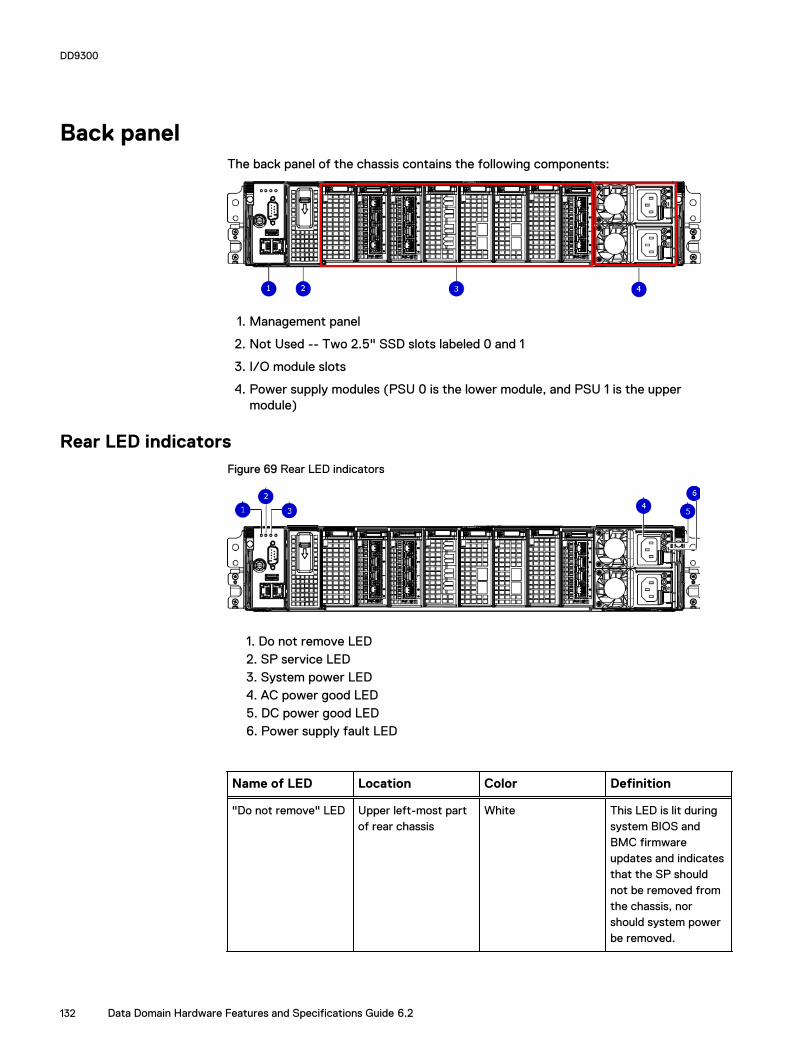
Back panelThe back panel of the chassis contains the following components:
1. Management panel
2. Not Used -- Two 2.5" SSD slots labeled 0 and 1
3. I/O module slots
4. Power supply modules (PSU 0 is the lower module, and PSU 1 is the uppermodule)
Rear LED indicatorsFigure 69 Rear LED indicators
1. Do not remove LED2. SP service LED3. System power LED4. AC power good LED5. DC power good LED6. Power supply fault LED
Name of LED Location Color Definition
"Do not remove" LED Upper left-most partof rear chassis
White This LED is lit duringsystem BIOS andBMC firmwareupdates and indicatesthat the SP shouldnot be removed fromthe chassis, norshould system powerbe removed.
DD9300
132 Data Domain Hardware Features and Specifications Guide 6.2

Name of LED Location Color Definition
SP service LED To the right of "Donot remove" LED
Amber l Solid amber - SPor a FRU insidethe SP requiresservice
l Blinking amber -blink rate reflectsone of thefollowing isbooting
n BIOS - 1/4 Hz
n POST - 1 Hz
n OS - 4 Hz
Drive Power/ActivityLED a
Left LED on the SSD Blue Lit blue when thedrive is powered.Blinks during driveactivity.
Drive Fault LED a Right LED on the SSD Amber Lit solid amber when adrive needs service.
System power LED Right-most LED onthe managementpanel
Blue SP has good, stablepower
PSU FRU LED - ACGood
Top LED on powersupply
Green AC input is asexpected
PSU FRU LED - DCGood
Middle LED on powersupply
Green DC output is asexpected
PSU FRU LED -Attention
Bottom LED on powersupply
Amber PSU has encountereda fault condition
a. The SSD is only present on DD6300 systems.
DD9300
Rear LED indicators 133

Figure 70 I/O module Power/Service LED location
1. I/O module power/service LED
Name of LED Location Color Definition
I/O module FRU LED- Figure 70 on page134
Ejector handle of I/Omodules
Green/Amber l Green - I/Omodule has powerand is functioningnormally
l Amber - I/Omodule hasencountered afault conditionand requiresservice
I/O port status LED(SAS, Fibre Channel,and opticalnetworking I/Omodules only)
One LED per I/Omodule port
Blue Lit when port isenabled. May flash ifSW "marks" theport. a
a. For RJ45 networking ports, the standard green link and amber activity LEDs are used.
DD9300
134 Data Domain Hardware Features and Specifications Guide 6.2

Figure 71 Onboard network port LEDs
1. Network port link LED2. Network port activity LED3. Dedicated IPMI port BMC0A4. Management interface EthMa
Name of LED Location Color Definition
Onboard network portLED - Link LED Figure71 on page 135
Top LED on networkport
Green l Lit when there isa link at1000BaseT and100BaseT speeds
l Off when the linkspeed is 10BaseTor there is no link
Onboard network portLED - Activity LED
Bottom LED onnetwork port
Amber Blinks when there istraffic on the port
I/O modulesI/O module slot numberingThe eight I/O module slots are enumerated as Slot 0 (on the left when viewed fromthe rear) through Slot 7. Ports on an I/O module are enumerated as 0 through 3, with0 being on the bottom.
Figure 72 I/O module slot numbering
1. Slot 02. Slot 13. Slot 24. Slot 35. Slot 46. Slot 5
DD9300
I/O modules 135

7. Slot 68. Slot 7
I/O modules are only supported in fixed configurations. The fixed configurationsdefine the exact slots into which the I/O modules may be inserted. The processorsdirectly drive the eight I/O module slots, meaning all slots are full performance.
The non-optional SAS, NVRAM, and 10GBaseT I/O modules are allocated to fixedslots. The optional Host Interface I/O modules are used for front end networking andFibre Channel connections. The quantity and type of these I/O modules iscustomizable, and there are many valid configurations.
DD9300 slot mapI/O module slots 3–6 contain optional Host Interface I/O modules and can containspecific I/O modules or no I/O modules at all. Slot 0, Slot 1, Slot 2, and Slot 7 arepopulated with the required I/O modules and are not optional.
Table 78 DD9300 I/O module slot mapping
Tier Slot 0 Slot 1 Slot 2 Slot 3 Slot 4 Slot 5 Slot 6 Slot 7
DLH NVRAM8g Model3
QuadPort 10GBase-T
Quad Port 6Gbps SAS
Quad Port10GbE SR,Quad Port10 GBase-T,or Dual Port16 GbpsFibreChannel
Quad Port10GbE SR,Quad Port 10GBase-T, orDual Port 16Gbps FibreChannel
Quad Port10GbE SR,Quad Port10 GBase-T,or Dual Port16 GbpsFibreChannel
Quad Port10GbE SR,Quad Port 10GBase-T, orDual Port 16Gbps FibreChannel
Quad Port 6Gbps SAS
DLH ExtendedRetention/DDCloud Tier
DLH HighAvailability
NVRAM8g Model3
QuadPort 10GBase-Tfor HAinterconnect
Quad Port 6Gbps SAS
Quad Port10GbE SR,Quad Port10 GBase-T,or Dual Port16 GbpsFibreChannel
Quad Port10GbE SR,Quad Port 10GBase-T, orDual Port 16Gbps FibreChannel
Quad Port10GbE SR,Quad Port10 GBase-T,or Dual Port16 GbpsFibreChannel
Quad Port10GbE SR,Quad Port 10GBase-T, orDual Port 16Gbps FibreChannel
Quad Port 6Gbps SAS
I/O module population rulesThe system chassis has eight slots for I/O modules. Slots 0, 1, 2, and 7 are reserved.Slots 3, 4, 5, and 6 support host interface I/O modules. The maximum supportednumber of any type of host interface I/O module is four.
Note
A maximum of three Quad Port 10 GBase-T I/O modules are supported in slots 3-6because of the mandatory Quad Port 10 GBase-T I/O module in slot 1.
The following table assigns rules for populating the I/O modules.
DD9300
136 Data Domain Hardware Features and Specifications Guide 6.2

Table 79 I/O module slot population rules
Step I/O module name Slots Notes
Step 1: Populatemandatory I/Omodules
NVRAM 8g Model 3 0 Mandatory for allconfigurations
Quad Port 10 GBase-T
1 Mandatory for allconfigurations
Quad Port 6 GbpsSAS
2 Mandatory for allconfigurations
Quad Port 6 GbpsSAS
7 Mandatory for allconfigurations
Step 2: Populate allQuad Port 10GbE SRI/O modules
Quad Port 10GbE SR 3, 4, 5, 6 Populate startingfrom the lowestavailable slot number.
Step 3: Populate allQuad Port 10 GBase-T I/O modules
Quad Port 10 GBase-T
3, 4, 5, 6 Populate startingfrom the lowestavailable slot number.With Quad Port 10GBase-T in slot 1, maxnumber of Quad Port10 GBase-T I/Omodules are limited to4.
Step 4: Populate allDual Port 16 GbpsFibre Channel I/Omodules
Dual Port 16 GbpsFibre Channel
6, 5, 4, 3 Populate startingfrom the highestavailable slot number.
DD9300
I/O module population rules 137

Internal system componentsThe following figure shows the layout of the CPUs and DIMMs inside the chassis. Thefront of the system is at the top of the figure.
Figure 73 CPU and memory locations
DIMMs overviewDual in-line memory modules (DIMM) come in various sizes, which must be configuredin a certain way. This topic can help you select the correct configuration whenservicing DIMMs.
The storage processor contains two Intel processors each with an integrated memorycontroller that supports four channels of memory. The storage processor allows twoDIMM slots per channel, so the storage processor supports a total of 16 DIMM slots.
DD9300 memory DIMM configuration
Table 80 DD9300 memory DIMM configuration
Tier Total Memory Memory DIMM Configuration
DD9300 DLH Expanded 384 GB 8 x 32 GB + 8 x 16 GB
DD9300 DLH 192 GB 4 x 32 GB + 4 x 16 GB
DD9300 DLH ExtendedRetention/DD Cloud Tier
384 GB 8 x 32 GB +8 x 16 GB
HA is supported with all available memory configurations.
To ensure maximum memory performance, there are memory DIMM population rulesfor best memory loading and interleaving. Table 81 on page 138 and Table 82 onpage 139 specify the DIMM location rules for various memory configurations:
Table 81 Memory locations - CPU 0
Channel A Channel B Channel D Channel C
Tier TotalMemory
0 1 2 3 4 5 6 7
DD9300 DLHExpanded
384 GB 32 GB 16 GB 32 GB 16 GB 16 GB 32 GB 16 GB 32 GB
DD9300
138 Data Domain Hardware Features and Specifications Guide 6.2

Table 81 Memory locations - CPU 0 (continued)
DD9300 DLH 192 GB 16 GB N/A 16 GB N/A N/A 32 GB N/A 32 GB
DD9300 DLHExtendedRetention/DDCloud Tier
384 GB 32 GB 16 GB 32 GB 16 GB 16 GB 32 GB 16 GB 32 GB
Table 82 Memory locations - CPU 1
Channel A Channel B Channel D Channel C
Tier TotalMemory
8 9 10 11 12 13 14 15
DD9300 DLHExpanded
384 GB 32 GB 16 GB 32 GB 16 GB 16 GB 32 GB 16 GB 32 GB
DD9300 DLH 192 GB 32 GB N/A 32 GB N/A N/A 16 GB N/A 16 GB
DD9300 DLHExtendedRetention/DDCloud Tier
384 GB 32 GB 16 GB 32 GB 16 GB 16 GB 32 GB 16 GB 32 GB
DD9300
DIMMs overview 139

DD9300
140 Data Domain Hardware Features and Specifications Guide 6.2

CHAPTER 10
DD9500
l System features............................................................................................... 142l System specifications....................................................................................... 143l DD9500 storage capacity................................................................................. 144l Front panel....................................................................................................... 146l Rear panel........................................................................................................ 150l I/O module slot assignments............................................................................ 155l Internal System Components............................................................................158
DD9500 141

System features
Table 83 DD9500 system features
Feature DD9500 (Baseconfiguration)
DD9500 (Expandedconfiguration)
Rack height 4U, supported in four-postracks only
4U, supported in four-postracks only
Rack mounting Rack mount kit includedwith each system.Adjustable between 24 -36 in. (60.9–76.2 cm).
Rack mount kit includedwith each system.Adjustable between 24 -36 in. (60.9–76.2 cm).
Power 4 hot-swappable powerunits, 2 pairs of 1 +1redundant
4 hot-swappable powerunits, 2 pairs of 1 +1redundant
Voltage 200–240 V~. Frequency:50 Hz to 60 Hz.
200–240 V~. Frequency:50 Hz to 60 Hz.
Processor 4 Intel EX processors. 4 Intel EX processors.
NVRAM One 8-GB NVRAM modulefor data integrity during apower outage
One 8-GB NVRAM modulefor data integrity during apower outage
Fans 8 hot-swappable fans,redundant
8 hot-swappable fans,redundant
Memory 32 x 8 GB DIMM (256 GB) 32 x 8 GB DIMM + 16 x 16GB DIMM (512 GB)
Internal drives 4 x 400 GB (base 10) hot-swappable solid statedrives (SSD)
4 x 400 GB (base 10) hot-swappable solid statedrives (SSD)
I/O module slots 11 I/O module (FibreChannel, Ethernet, andSAS) slots. ReplaceableI/O modules are not hot-swappable. See I/O module slotassignments on page 155
11 I/O module (FibreChannel, Ethernet, andSAS) slots. ReplaceableI/O modules are not hot-swappable. See I/O module slotassignments on page 155
Supported capacity Non-extended retention 540 TB 1080 TB
DD Cloud Tier N/A 2160 TBa
Extended retention N/A 1080 TBb
High availability support Yes Yes
HA private interconnect 4 10 GbE optical ports 4 10 GbE optical ports
External SSD shelf Optional 1 x 8 drive SSDshelf
Optional 1 x 15 drive SSDshelf
a. DD Cloud Tier requires five ES30 shelves fully populated with 4 TB drives to store DD Cloud Tier metadata.
DD9500
142 Data Domain Hardware Features and Specifications Guide 6.2

Table 83 DD9500 system features (continued)
b. Extended retention not available on HA configurations
System specifications
Table 84 DD9500/DD9800 system specifications
Model Watts BTU/hr Power (VA) Weight Width Depth Height
DD9500/DD9800
1887 6444 1981 117 lb / 53.2kg
19 in / 48.3cm
29.5 in / 74.9cm
7 in / 17.8 cm
l Operating temperature: 50° to 95° F (10° to 35° C), derate 1.1° C per 1000 feet,above 7500 feet up to 10,000 feet
l Operating humidity: 20% to 80%, non-condensing
l Non-operating temperature: -40° to +149° F (-40° to +65° C)
l Operating acoustic noise: Sound power, LWAd, is 7.7 bels.
DD9500
System specifications 143

DD9500 storage capacityThe table lists the capacities of the systems. Data Domain system internal indexes andother product components use variable amounts of storage, depending on the type ofdata and the sizes of files. If you send different data sets to otherwise identicalsystems, one system may, over time, have room for more or less actual backup datathan another.
Note
Data Domain system commands compute and display amounts of disk space or data asdecimal multiples of certain powers of two (210, 220, 230, and so forth). For example, 7GiB of disk space = 7 x 230 bytes = 7 x 1,073,741,824 bytes. Data Domain refers to thisprocess as Base 2 calculation.
Table 85 DD9500 storage capacity
System/InstalledMemory
Internal Disks Raw Storage(Base 10)
Data StorageSpace (Base 2Calculation)
Data StorageSpace (Base10Calculation)
DD9500(3 SAS I/Omodules)
256 GB
2.5 in.; 4 x 400GB SATA SSDNo User Data
540 TB(external)
392.9 TiB 432 TB
DD9500(3 SAS I/Omodules)
512 GB
2.5 in.; 4 x 400GB SATA SSDNo User Data
1,080 TB(external)
786.8 TiB 864 TB
DD9500 with DDCloud Tiersoftware(4 SAS I/Omodules)
512 GB
2.5 in.; 4 x 400GB SATA SSDNo User Data
3,240 TB(external)
2360.4 TiB 2592 TB
DD9500 withExtendedRetention (ER)software(4 SAS I/Omodules)
512 GB
2.5 in.; 4 x 400GB SATA SSDNo User Data
2,160 TB(external)
1573.6 TiB 1728 TB
Note
For information about Data Domain expansion shelves and guidelines on using amixture of shelves, see the Data Domain ES30 Expansion Shelf Hardware Guide and DataDomain DS60 Expansion Shelf Hardware Guide.
DD9500
144 Data Domain Hardware Features and Specifications Guide 6.2

Table 86 DD9500 with ES30 SAS shelves
DD9500 DD9500
Memory (GB) 256 512
SAS I/O modules x ports permodule
3x4 3x4
ES30 support (TB) SAS 30, 45, 60 SAS 30, 45, 60
Maximum shelves per set 5 5
Maximum number of sets 6 6
Note
ES30 SATA shelves are supported when upgrading from an older Data Domain singlenode system, but are not supported with HA pairs or new installations.
Table 87 DD9500 with DS60 shelves
DD9500 DD9500
Memory (GB) 256 512
SAS I/O modules x ports permodule
3x4 3x4
DS60 support (TB) SAS 45, 60 SAS 45, 60
Maximum shelves per set 4 4
Maximum number of sets 6 6
DD9500
DD9500 storage capacity 145

Front panelThe four solid state drives (SSDs), the storage processor (SP), and the fans areaccessed from the front of the system. The SP must be pulled out to provide accessto the DIMMs. The fans are accessed without pulling or removing the SP and they arehot-swappable. The photo shows the interfaces on the front of the system.
Figure 74 Front panel components
1. SSD slot 02. SSD slot 13. SSD slot 24. SSD slot 35. Front LEDs6. USB ports7. Power button8. Fan tray thumbscrew (left)9. SP module thumbscrew to secure the ejector handle10. Fan tray thumbscrew (right)
Front LED indicatorsOn the front panel to the right of SSD #4 (in Slot 3) are 3 LEDs that show high levelsystem status. The System Power LED glows blue to show the system is powered on.
Note
The system can have power (be plugged in) but the blue LEDs are off if the system ispowered off.
The SP Service LED is normally off, but glows amber whenever the storage processor(SP) requires service. The Enclosure Service LED is normally off, but glows amberwhenever the SP or other replaceable parts require service. The System Power andEnclosure Service LEDs are visible through the front bezel.
DD9500
146 Data Domain Hardware Features and Specifications Guide 6.2

Figure 75 Service LEDs
1. SP service LED — Amber light indicates that the SP or one of its componentsneeds service.2. Enclosure Service LED — This is normally off, but amber light indicates that theenclosure or something within the enclosure— the fans, SP, I/O modules,management module etc—requires service.3. System power LED — Blue light indicates system running
DD9500
Front LED indicators 147

The power button shown in the picture is used when a system needs to be powered upafter a shut down using the system poweroff command. Once power is restoredthe system power LED light turns blue.
Figure 76 Power button
1. System power LED — Blue light indicates system running2. Power button
The LEDs in the front are shown in the following figure.
Figure 77 Front LEDs
1. SSD LED in slot 02. SSD LED in slot 13. SSD LED in slot 24. SSD LED in slot 35. System power LED — Blue light indicates system running
DD9500
148 Data Domain Hardware Features and Specifications Guide 6.2

Table 88 Front panel LED status indicators
Part Description or Location State
System, SP fault Exclamation point within atriangle
Dark indicates normaloperation. Amber indicatesfailure.
System, chassis fault Exclamation point within atriangle
Dark indicates normaloperation. Amber indicates afault condition.
SSD Top LED Solid blue, disk ready, blinkswhile busy.
SSD Bottom LED Dark indicates healthy. Solidamber indicates disk fail.
Solid-state drivesA system contains 4 hot-swappable 2.5 in. 400 GB solid-state drives (SSD) located inthe front. There are four drive bays numbered 0–3 from left to right. A dual drivefailure allows the system to operate without disruption.
Each drive has a blue colored power LED and an amber fault LED.
Figure 78 SSD drives
1. Slot 02. Slot 13. Slot 24. Slot 3
DD9500
Solid-state drives 149

Rear panelIn the rear of the system, the top section contains the 4 power supply units. In themiddle of the section, on the left, is serial number tag location. To the right of theserial number tag location is the management module. The lower section contains theNVRAM and the I/O modules numbered 0 through 11 from left to right. The photoshows the hardware features and interfaces on the rear of the system.
Figure 79 Features on rear of chassis
1. Power supply units2. Serial number tag3. Management module4. NVRAM and I/O modules (slots 0-11)
The figure shows the location of the serial number tag on the left of the managementmodule.
Figure 80 Serial number tag location
DD9500
150 Data Domain Hardware Features and Specifications Guide 6.2
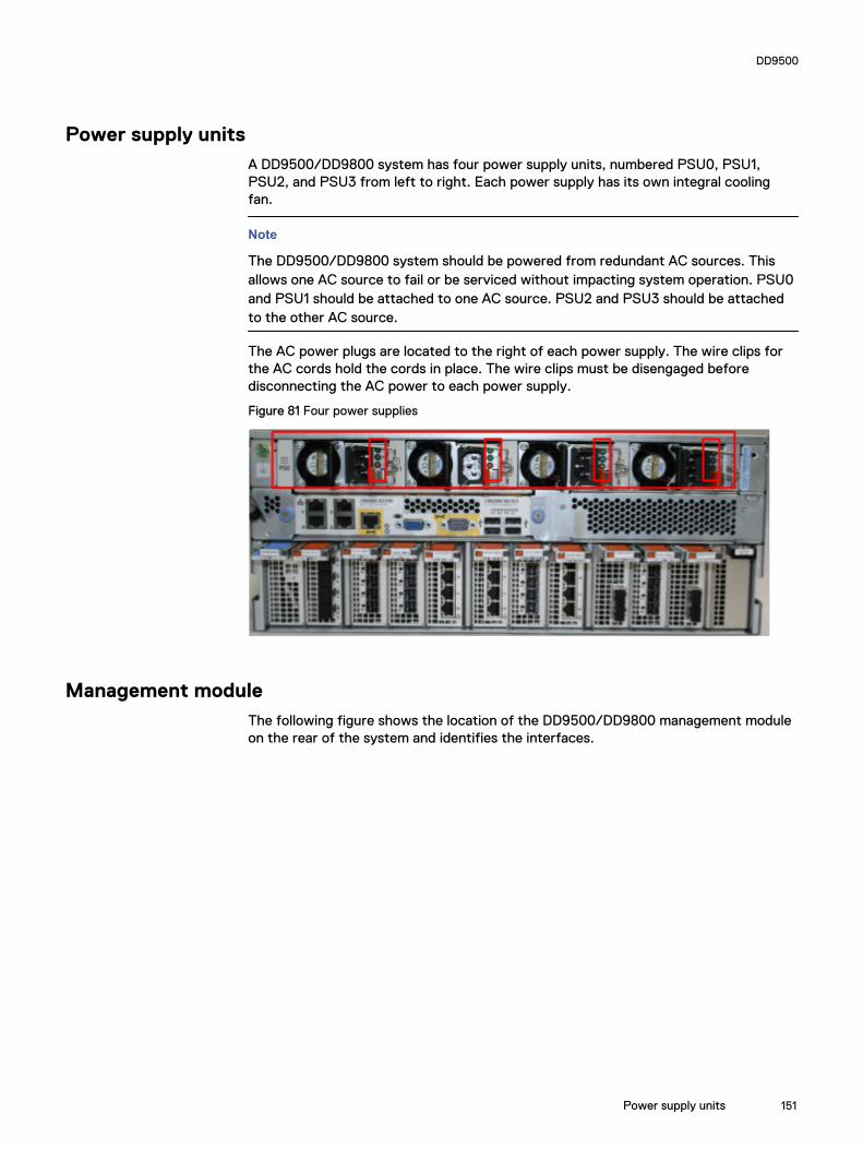
Power supply unitsA DD9500/DD9800 system has four power supply units, numbered PSU0, PSU1,PSU2, and PSU3 from left to right. Each power supply has its own integral coolingfan.
Note
The DD9500/DD9800 system should be powered from redundant AC sources. Thisallows one AC source to fail or be serviced without impacting system operation. PSU0and PSU1 should be attached to one AC source. PSU2 and PSU3 should be attachedto the other AC source.
The AC power plugs are located to the right of each power supply. The wire clips forthe AC cords hold the cords in place. The wire clips must be disengaged beforedisconnecting the AC power to each power supply.
Figure 81 Four power supplies
Management moduleThe following figure shows the location of the DD9500/DD9800 management moduleon the rear of the system and identifies the interfaces.
DD9500
Power supply units 151

Figure 82 Management module
1. Left blue thumbscrew to loosen the management module2. 4 x 1000BaseT Ethernet ports (For details, see the picture - 1000BaseT Ethernetports)3. Service network port (IPMI, 1000BaseT Ethernet port)4. Service LED5. VGA port6. Serial port7. Four USB ports8. Right blue thumbscrew to loosen the management module
Figure 83 1000BaseT Ethernet ports
- Lower left port: physical #0, logical ethMa- Top left port: physical #1, logical ethMb- Lower right port: physical #2, logical ethMc- Top right port: physical #3, logical ethMd
Rear LED indicators
The rear elements containing LEDs include each power supply, each I/O module, andthe management module.
DD9500
152 Data Domain Hardware Features and Specifications Guide 6.2

The figure shows the rear LEDS.
Figure 84 Rear LEDs
1. Management module service LEDs2. Power supply LEDs3. NVRAM LEDs4. I/O Module LEDs
The power supply LEDs include:
l AC LED on top
l DC LED in the middle
l Service Required LED on the bottom
Figure 85 Power supply LEDs
Table 89 Rear LED status indicators
Part Description or Location State
Power supply AC LED Steady green indicates normalAC input power.
DD9500
Rear LED indicators 153

Table 89 Rear LED status indicators (continued)
Part Description or Location State
Power supply DC LED Steady green indicates normalDC output power.
Power supply Service LED Solid amber indicates a failedpower supply.
I/O module I/O module handle Solid green means I/O modulefunctioning normally. Amberindicates a fault condition.Each I/O module also has perport LEDs. These LEDs areblue on the FC, and SAS I/Omodules. They light when theport is active.
Management module Bicolor LED Solid green meansmanagement modulefunctioning normally. Amberindicates that themanagement module requiresservice.
Available I/O modulesI/O modules may include:
l Quad port Ethernet 10GBase-SR Optical with LC connectors
l Quad port Ethernet 10GBase-CX1 Direct Attach Copper with SPF+ module
l Quad port Ethernet 10GBase-T Copper
l Dual port 16 Gbps Fibre Channel
l Quad port 6 Gbps SAS
I/O module port physical mappingI/O module ports are numbered starting with 0. When the I/O modules are insertedvertically into the system chassis, port 0 is on the bottom.
I/O module port logical mappingThe numerical port labels on the I/O modules are identified logically in the DD OSsoftware by the following descriptions:
l I/O module type
l I/O module slot
l Alphabetic character corresponding to the physical port number
The following example is based on a four-port Ethernet I/O module installed in slot 1 ofthe system chassis.
Table 90 Physical to logical port mapping example
Physical port Logical identifier
0 eth1a
DD9500
154 Data Domain Hardware Features and Specifications Guide 6.2
Table 90 Physical to logical port mapping example (continued)
Physical port Logical identifier
1 eth1b
2 eth1c
3 eth1d
Ethernet I/O module optionsThe available Ethernet I/O modules are:
l Dual Port 10GBase-SR Optical with LC connectors
l Dual Port 10GBase-CX1 Direct Attach Copper with SPF+ module
l Quad Port 1000Base-T Copper with RJ-45 connectors
l Quad port 2 port 1000Base-T Copper (RJ45) /2 port 1000Base-SR Optical
Fibre Channel I/O modulesA Fibre Channel (FC) I/O module is a dual-port Fibre Channel module. Up to four FCI/O modules may be installed. The optional virtual tape library (VTL) feature requiresat least one FC I/O module. Boost over Fibre Channel is an optional feature andrequires at least one FC I/O module. A maximum of four FC I/O modules may beinstalled in a system using either VTL or the Boost protocol or a combination of bothprotocols.
SAS I/O modulesDD9500 systems have three quad-port SAS I/O modules installed in slots 2, 3 and 6.Systems configured with DD Extended Retention (ER) or DD Cloud Tier softwareoptions require an additional SAS I/O module in slot 9.
I/O module slot assignmentsThe following figure shows the location of the NVRAM and I/O modules.
DD9500
Ethernet I/O module options 155

Figure 86 Location of NVRAM and I/O modules
1. NVRAM module—slot 02. I/O modules—slots 1 to 11 (See the I/O module slot assignments table.)
The table shows the I/O module slot assignments for the DD9500 system. Each typeof I/O module is restricted to certain slots.
Table 91 DD9500 I/O module slot assignments
Slot Baseconfiguration
HA ER or DD Cloud Tier DD Cloud Tier and HA
0 NVRAM NVRAM NVRAM NVRAM
1 Fibre Channel (FC),Ethernet or empty
Fibre Channel (FC),Ethernet or empty
Fibre Channel (FC),Ethernet or empty
Fibre Channel (FC),Ethernet or empty
2 SAS SAS SAS SAS
3 SAS SAS SAS SAS
4 FC, Ethernet orempty
FC, Ethernet or empty FC, Ethernet or empty FC, Ethernet or empty
5 FC, Ethernet orempty
FC, Ethernet or empty FC, Ethernet or empty FC, Ethernet or empty
6 SAS SAS SAS SAS
7 FC, Ethernet orempty
FC, Ethernet or empty FC, Ethernet or empty FC, Ethernet or empty
8 FC, Ethernet orempty
FC, Ethernet or empty FC, Ethernet or empty FC, Ethernet or empty
9 Not available(contains a filler)
Not available (containsa filler)
SAS SAS
10 FC, Ethernet orempty
FC, Ethernet or empty FC, Ethernet or empty FC, Ethernet or empty
11 FC, Ethernet orempty
10 Gb optical Ethernetfor interconnect
FC, Ethernet or empty 10 Gb optical Ethernet forinterconnect between the
DD9500
156 Data Domain Hardware Features and Specifications Guide 6.2

Table 91 DD9500 I/O module slot assignments (continued)
Slot Baseconfiguration
HA ER or DD Cloud Tier DD Cloud Tier and HA
between the primaryand standby nodes inthe HA pair.
primary and standby nodesin the HA pair.
Slot addition rulesThis system has 12 slots for I/O modules. Slots 0, 2, 3, 6, 9, and 11 are reserved formandatory I/O modules. Slots 1, 4, 5, 7, 8, and 10 support optional host interface I/Omodules. The maximum supported number of any type of host interface (Ethernet orFC) I/O module is four.
Note
The maximum number of host interface I/O modules that are listed above does notinclude the 10 GbE Optical I/O module for the HA interconnect. The HA interconnectis a fifth Ethernet module, but it is reserved for communication between the twonodes of an HA pair, and is not available for host connections.
The maximum number of I/O modules, including both mandatory and optional I/Omodules, supported in a system varies by configuration:
l Single node: 10
l HA: 10
l DD Extended Retention: 10
l DD Cloud Tier: 10
l HA + DD Cloud Tier: 11
Three I/O module slots are tied to each CPU in the system. When installing I/Omodules, balance the load across the CPUs. The following table shows the CPU to slotmappings.
CPU I/O module slots
0 0, 1, 2
1 3, 4, 5
2 6, 7, 8
3 9, 10, 11
The following table assigns rules for populating the I/O modules.
Table 92 I/O module slot population rules
Step I/O module type Slots Notes
1: Populate mandatoryI/O modules
NVRAM 0
Quad Port SAS 2
Quad Port SAS 3
DD9500
Slot addition rules 157

Table 92 I/O module slot population rules (continued)
Step I/O module type Slots Notes
Quad Port SAS 6
Quad Port SAS 9 This slot remainsempty if the systemdoes not use DDCloud Tier or DDExtended Retention.
Quad Port 10GbEOptical
11 This slot remainsempty if the systemdoes not use HA.
2: Populate hostinterface I/O modules
l Quad Port 10GbESR
l Quad Port 10GBase-T
l Dual Port 16 GbpsFibre Channel
1, 4, 5, 7, 8, 10 Install host interfaceI/O modules in theremaining slots. Installthe I/O modules tobalance the loadacross the CPUs. Donot place twoEthernet or two FCI/O modules on oneCPU.a
a. HA systems are the exception to this guidance, as a Quad Port 10GbE SR I or Quad Port 10GBase-T /O module can be added in slot 10 alongside the HA interconnect I/O module inslot 11.
Internal System ComponentsThe storage processor (SP) is a subassembly within the chassis that contains thememory risers with the DIMMs and a fan tray with fan modules. The SP module alsocontains the 4 CPUs, which cannot be removed or replaced.
l The memory risers tray, which contains 8 memory risers with DIMMs, can beaccessed from the front of the SP module. The memory risers are not hotswappable
l The fan tray, which contains 8 fan modules, can be accessed from the front of theSP module. The fans are hot swappable.
The DIMMS can be accessed by pulling the entire SP module away from the chassis.Depending on the model, there are DIMMs totaling:
l 256 GB or 512 GB for a DD9500 system.
l 256 GB or 768 GB for a DD9800 system.
The figures show the location of the SP module, the DIMM risers accessed from apartly removed SP module, and the fan tray partly removed.
Do not lift the DD9500/DD9800 system, or the storage processor (SP) module, orany modules by the handle. The handle is not designed to support the weight of thepopulated shelf. Also do not carry the DD9500/DD9800 system or the SP by thehandle. The handles are only intended to be used to insert or remove the SP module.
DD9500
158 Data Domain Hardware Features and Specifications Guide 6.2

Figure 87 SP module
Figure 88 Releasing a memory riser
1. Left riser card ejector handle2. Release button3. Right riser card ejector handle
DD9500
Internal System Components 159
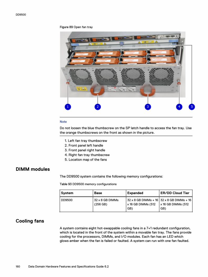
Figure 89 Open fan tray
Note
Do not loosen the blue thumbscrew on the SP latch handle to access the fan tray. Usethe orange thumbscrews on the front as shown in the picture.
1. Left fan tray thumbscrew2. Front panel left handle3. Front panel right handle4. Right fan tray thumbscrew5. Location map of the fans
DIMM modulesThe DD9500 system contains the following memory configurations:
Table 93 DD9500 memory configurations
System Base Expanded ER/DD Cloud Tier
DD9500 32 x 8 GB DIMMs(256 GB)
32 x 8 GB DIMMs + 16x 16 GB DIMMs (512GB)
32 x 8 GB DIMMs + 16x 16 GB DIMMs (512GB)
Cooling fansA system contains eight hot-swappable cooling fans in a 7+1 redundant configuration,which is located in the front of the system within a movable fan tray. The fans providecooling for the processors, DIMMs, and I/O modules. Each fan has an LED whichglows amber when the fan is failed or faulted. A system can run with one fan faulted.
DD9500
160 Data Domain Hardware Features and Specifications Guide 6.2

CHAPTER 11
DD9800
l DD9800 system features.................................................................................. 162l DD9800 system specifications..........................................................................163l DD9800 storage capacity................................................................................. 164l DD9800 front panel.......................................................................................... 166l Rear panel.........................................................................................................170l I/O module slot assignments.............................................................................175l Internal system components............................................................................. 178
DD9800 161

DD9800 system features
Table 94 DD9800 system features
Feature DD9800 (Baseconfiguration)
DD9800 (Expandedconfiguration)
Rack height 4U, supported in four-postracks only
4U, supported in four-postracks only
Rack mounting Rack mount kit includedwith each system.Adjustable between 24 -36 in. (60.9–76.2 cm).
Rack mount kit includedwith each system.Adjustable between 24 -36 in. (60.9–76.2 cm).
Power 4 hot-swappable powerunits, 2 pairs of 1 +1redundant
4 hot-swappable powerunits, 2 pairs of 1 +1redundant
Voltage 200–240 V~. Frequency:50 Hz to 60 Hz.
200–240 V~. Frequency:50 Hz to 60 Hz.
Processor 4 Intel EX processors. 4 Intel EX processors.
NVRAM One 8-GB NVRAM modulefor data integrity during apower outage
One 8-GB NVRAM modulefor data integrity during apower outage
Fans 8 hot-swappable fans,redundant
8 hot-swappable fans,redundant
Memory 32 x 8 GB DIMM (256 GB) 32 x 8 GB DIMM + 32 x 16GB DIMM (768 GB)
Internal drives 4 x 400 GB (base 10) hot-swappable solid statedrives (SSD)
4 x 400 GB (base 10) hot-swappable solid statedrives (SSD)
I/O module slots 11 I/O module (FibreChannel, Ethernet, andSAS) slots. ReplaceableI/O modules are not hot-swappable. See I/O module slotassignments on page 155
11 I/O module (FibreChannel, Ethernet, andSAS) slots. ReplaceableI/O modules are not hot-swappable. See I/O module slotassignments on page 155
Supported capacity Non-extended retention 630 TB 1260 TB
DD Cloud Tier N/A 2520 TB a
Extended retention N/A 1260 TB b
High availability support Yes Yes
HA private interconnect 4 10 GbE optical ports 4 10 GbE optical ports
External SSD shelf 1 x 8 drive SSD shelf 1 x 15 drive SSD shelf
a. DD Cloud Tier requires five ES30 shelves fully populated with 4 TB drives to store DD Cloud Tier metadata.b. Extended retention not available on HA configurations
DD9800
162 Data Domain Hardware Features and Specifications Guide 6.2
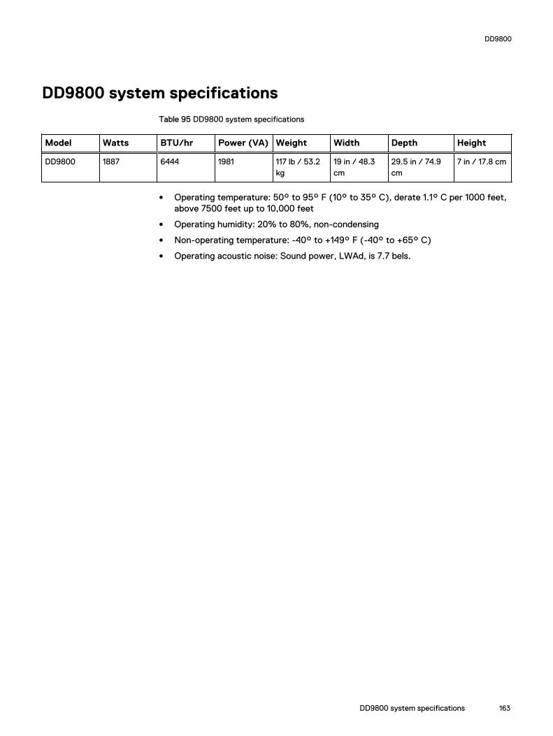
DD9800 system specifications
Table 95 DD9800 system specifications
Model Watts BTU/hr Power (VA) Weight Width Depth Height
DD9800 1887 6444 1981 117 lb / 53.2kg
19 in / 48.3cm
29.5 in / 74.9cm
7 in / 17.8 cm
l Operating temperature: 50° to 95° F (10° to 35° C), derate 1.1° C per 1000 feet,above 7500 feet up to 10,000 feet
l Operating humidity: 20% to 80%, non-condensing
l Non-operating temperature: -40° to +149° F (-40° to +65° C)
l Operating acoustic noise: Sound power, LWAd, is 7.7 bels.
DD9800
DD9800 system specifications 163
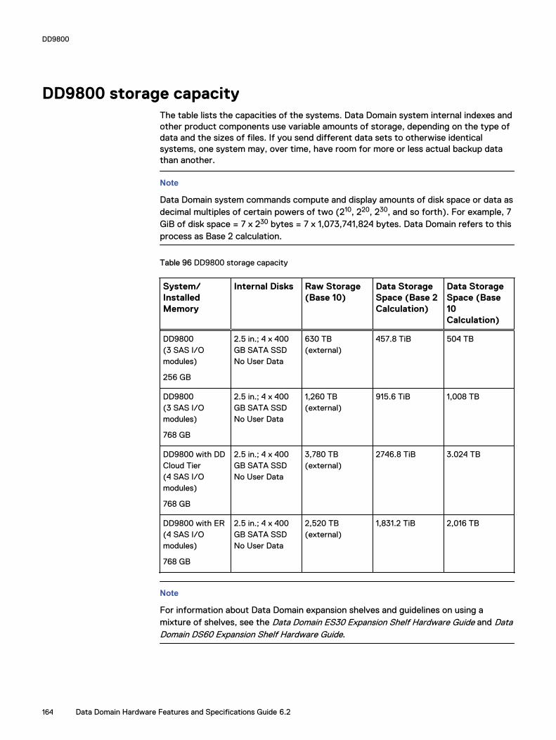
DD9800 storage capacityThe table lists the capacities of the systems. Data Domain system internal indexes andother product components use variable amounts of storage, depending on the type ofdata and the sizes of files. If you send different data sets to otherwise identicalsystems, one system may, over time, have room for more or less actual backup datathan another.
Note
Data Domain system commands compute and display amounts of disk space or data asdecimal multiples of certain powers of two (210, 220, 230, and so forth). For example, 7GiB of disk space = 7 x 230 bytes = 7 x 1,073,741,824 bytes. Data Domain refers to thisprocess as Base 2 calculation.
Table 96 DD9800 storage capacity
System/InstalledMemory
Internal Disks Raw Storage(Base 10)
Data StorageSpace (Base 2Calculation)
Data StorageSpace (Base10Calculation)
DD9800(3 SAS I/Omodules)
256 GB
2.5 in.; 4 x 400GB SATA SSDNo User Data
630 TB(external)
457.8 TiB 504 TB
DD9800(3 SAS I/Omodules)
768 GB
2.5 in.; 4 x 400GB SATA SSDNo User Data
1,260 TB(external)
915.6 TiB 1,008 TB
DD9800 with DDCloud Tier(4 SAS I/Omodules)
768 GB
2.5 in.; 4 x 400GB SATA SSDNo User Data
3,780 TB(external)
2746.8 TiB 3.024 TB
DD9800 with ER(4 SAS I/Omodules)
768 GB
2.5 in.; 4 x 400GB SATA SSDNo User Data
2,520 TB(external)
1,831.2 TiB 2,016 TB
Note
For information about Data Domain expansion shelves and guidelines on using amixture of shelves, see the Data Domain ES30 Expansion Shelf Hardware Guide and DataDomain DS60 Expansion Shelf Hardware Guide.
DD9800
164 Data Domain Hardware Features and Specifications Guide 6.2

Table 97 DD9800 with ES30 SAS shelves
DD9800 DD9800
Memory (GB) 256 768
SAS I/O modules x ports permodule
3x4 3x4
ES30 support (TB) SAS 30, 45, 60 SAS 30, 45, 60
Maximum shelves per set 5 5
Maximum number of sets 6 6
Note
ES30 SATA shelves are supported when upgrading from an older Data Domain singlenode system, but are not supported with HA pairs or new installations.
Table 98 DD9800 with DS60 shelves
DD9800 DD9800
Memory (GB) 256 768
SAS I/O modules x ports permodule
3x4 3x4
DS60 support (TB) SAS 45, 60 SAS 45, 60
Maximum shelves per set 4 4
Maximum number of sets 6 6
DD9800
DD9800 storage capacity 165

DD9800 front panelThe four solid state drives (SSDs), the storage processor (SP), and the fans areaccessed from the front of the system. The SP must be pulled out to provide accessto the DIMMs. The fans are accessed without pulling or removing the SP and they arehot-swappable. The photo shows the interfaces on the front of the system.
Figure 90 Front panel components
1. SSD slot 02. SSD slot 13. SSD slot 24. SSD slot 35. Front LEDs6. USB ports7. Power button8. Fan tray thumbscrew (left)9. SP module thumbscrew to secure the ejector handle10. Fan tray thumbscrew (right)
Front LED indicatorsOn the front panel to the right of SSD #4 (in Slot 3) are 3 LEDs that show high levelsystem status. The System Power LED glows blue to show the system is powered on.
Note
The system can have power (be plugged in) but the blue LEDs are off if the system ispowered off.
The SP Service LED is normally off, but glows amber whenever the storage processor(SP) requires service. The Enclosure Service LED is normally off, but glows amberwhenever the SP or other replaceable parts require service. The System Power andEnclosure Service LEDs are visible through the front bezel.
DD9800
166 Data Domain Hardware Features and Specifications Guide 6.2

Figure 91 Service LEDs
1. SP service LED — Amber light indicates that the SP or one of its componentsneeds service.2. Enclosure Service LED — This is normally off, but amber light indicates that theenclosure or something within the enclosure— the fans, SP, I/O modules,management module etc—requires service.3. System power LED — Blue light indicates system running
DD9800
Front LED indicators 167

The power button shown in the picture is used when a system needs to be powered upafter a shut down using the system poweroff command. Once power is restoredthe system power LED light turns blue.
Figure 92 Power button
1. System power LED — Blue light indicates system running2. Power button
The LEDs in the front are shown in the following figure.
Figure 93 Front LEDs
1. SSD LED in slot 02. SSD LED in slot 13. SSD LED in slot 24. SSD LED in slot 35. System power LED — Blue light indicates system running
DD9800
168 Data Domain Hardware Features and Specifications Guide 6.2

Table 99 Front panel LED status indicators
Part Description or Location State
System, SP fault Exclamation point within atriangle
Dark indicates normaloperation. Amber indicatesfailure.
System, chassis fault Exclamation point within atriangle
Dark indicates normaloperation. Amber indicates afault condition.
SSD Top LED Solid blue, disk ready, blinkswhile busy.
SSD Bottom LED Dark indicates healthy. Solidamber indicates disk fail.
Solid-state drivesA system contains 4 hot-swappable 2.5 in. 400 GB solid-state drives (SSD) located inthe front. There are four drive bays numbered 0–3 from left to right. A dual drivefailure allows the system to operate without disruption.
Each drive has a blue colored power LED and an amber fault LED.
Figure 94 SSD drives
1. Slot 02. Slot 13. Slot 24. Slot 3
DD9800
Solid-state drives 169

Rear panelIn the rear of the system, the top section contains the 4 power supply units. In themiddle of the section, on the left, is serial number tag location. To the right of theserial number tag location is the management module. The lower section contains theNVRAM and the I/O modules numbered 0 through 11 from left to right. The photoshows the hardware features and interfaces on the rear of the system.
Figure 95 Features on rear of chassis
1. Power supply units2. Serial number tag3. Management module4. NVRAM and I/O modules (slots 0-11)
The figure shows the location of the serial number tag on the left of the managementmodule.
Figure 96 Serial number tag location
DD9800
170 Data Domain Hardware Features and Specifications Guide 6.2

Power supply unitsA DD9800 system has four power supply units, numbered PSU0, PSU1, PSU2, andPSU3 from left to right. Each power supply has its own integral cooling fan.
Note
The DD9800 system should be powered from redundant AC sources. This allows oneAC source to fail or be serviced without impacting system operation. PSU0 and PSU1should be attached to one AC source. PSU2 and PSU3 should be attached to theother AC source.
The AC power plugs are located to the right of each power supply. The wire clips forthe AC cords hold the cords in place. The wire clips must be disengaged beforedisconnecting the AC power to each power supply.
Figure 97 Four power supplies
Management moduleThe following figure shows the location of the DD9500/DD9800 management moduleon the rear of the system and identifies the interfaces.
Figure 98 Management module
DD9800
Power supply units 171

1. Left blue thumbscrew to loosen the management module2. 4 x 1000BaseT Ethernet ports (For details, see the picture - 1000BaseT Ethernetports)3. Service network port (IPMI, 1000BaseT Ethernet port)4. Service LED5. VGA port6. Serial port7. Four USB ports8. Right blue thumbscrew to loosen the management module
Figure 99 1000BaseT Ethernet ports
- Lower left port: physical #0, logical ethMa- Top left port: physical #1, logical ethMb- Lower right port: physical #2, logical ethMc- Top right port: physical #3, logical ethMd
Rear LED indicators
The rear elements containing LEDs include each power supply, each I/O module, andthe management module.
The figure shows the rear LEDS.
DD9800
172 Data Domain Hardware Features and Specifications Guide 6.2

Figure 100 Rear LEDs
1. Management module service LEDs2. Power supply LEDs3. NVRAM LEDs4. I/O Module LEDs
The power supply LEDs include:
l AC LED on top
l DC LED in the middle
l Service Required LED on the bottom
Figure 101 Power supply LEDs
Table 100 Rear LED status indicators
Part Description or Location State
Power supply AC LED Steady green indicates normalAC input power.
Power supply DC LED Steady green indicates normalDC output power.
DD9800
Rear LED indicators 173

Table 100 Rear LED status indicators (continued)
Part Description or Location State
Power supply Service LED Solid amber indicates a failedpower supply.
I/O module I/O module handle Solid green means I/O modulefunctioning normally. Amberindicates a fault condition.Each I/O module also has perport LEDs. These LEDs areblue on the FC, and SAS I/Omodules. They light when theport is active.
Management module Bicolor LED Solid green meansmanagement modulefunctioning normally. Amberindicates that themanagement module requiresservice.
Available I/O modulesI/O modules may include:
l Quad port Ethernet 10GBase-SR Optical with LC connectors
l Quad port Ethernet 10GBase-CX1 Direct Attach Copper with SPF+ module
l Quad port Ethernet 10GBase-T Copper
l Dual port 16 Gbps Fibre Channel
l Quad port 6 Gbps SAS
I/O module port physical mappingI/O module ports are numbered starting with 0. When the I/O modules are insertedvertically into the system chassis, port 0 is on the bottom.
I/O module port logical mappingThe numerical port labels on the I/O modules are identified logically in the DD OSsoftware by the following descriptions:
l I/O module type
l I/O module slot
l Alphabetic character corresponding to the physical port number
The following example is based on a four-port Ethernet I/O module installed in slot 1 ofthe system chassis.
Table 101 Physical to logical port mapping example
Physical port Logical identifier
0 eth1a
1 eth1b
DD9800
174 Data Domain Hardware Features and Specifications Guide 6.2

Table 101 Physical to logical port mapping example (continued)
Physical port Logical identifier
2 eth1c
3 eth1d
Ethernet I/O module optionsThe available Ethernet I/O modules are:
l Dual Port 10GBase-SR Optical with LC connectors
l Dual Port 10GBase-CX1 Direct Attach Copper with SPF+ module
l Quad Port 1000Base-T Copper with RJ-45 connectors
l Quad port 2 port 1000Base-T Copper (RJ45) /2 port 1000Base-SR Optical
Fibre Channel I/O modulesA Fibre Channel (FC) I/O module is a dual-port Fibre Channel module. Up to four FCI/O modules may be installed. The optional virtual tape library (VTL) feature requiresat least one FC I/O module. Boost over Fibre Channel is an optional feature andrequires at least one FC I/O module. A maximum of four FC I/O modules may beinstalled in a system using either VTL or the Boost protocol or a combination of bothprotocols.
SAS I/O modulesDD9800 systems have three quad-port SAS I/O modules installed in slots 2, 3 and 6.Systems configured with DD Extended Retention (ER) or DD Cloud Tier softwareoptions require an additional SAS I/O module in slot 9.
I/O module slot assignmentsThe following figure shows the location of the NVRAM and I/O modules.
Figure 102 Location of NVRAM and I/O modules
DD9800
Ethernet I/O module options 175

1. NVRAM module—slot 02. I/O modules—slots 1 to 11 (See the I/O module slot assignments table.)
The table shows the I/O module slot assignments for the DD9800 system. Each typeof I/O module is restricted to certain slots.
Table 102 DD9800 I/O module slot assignments
Slot Baseconfiguration
HA ER or DD Cloud Tier DD Cloud Tier and HA
0 NVRAM NVRAM NVRAM NVRAM
1 Fibre Channel (FC),Ethernet or empty
Fibre Channel (FC),Ethernet or empty
Fibre Channel (FC),Ethernet or empty
Fibre Channel (FC),Ethernet or empty
2 SAS SAS SAS SAS
3 SAS SAS SAS SAS
4 FC, Ethernet orempty
FC, Ethernet or empty FC, Ethernet or empty FC, Ethernet or empty
5 FC, Ethernet orempty
FC, Ethernet or empty FC, Ethernet or empty FC, Ethernet or empty
6 SAS SAS SAS SAS
7 FC, Ethernet orempty
FC, Ethernet or empty FC, Ethernet or empty FC, Ethernet or empty
8 FC, Ethernet orempty
FC, Ethernet or empty FC, Ethernet or empty FC, Ethernet or empty
9 Not available(contains a filler)
Not available (containsa filler)
SAS SAS
10 FC, Ethernet orempty
FC, Ethernet or empty FC, Ethernet or empty FC, Ethernet or empty
11 FC, Ethernet orempty
10 Gb optical Ethernetfor interconnectbetween the primaryand standby nodes inthe HA pair.
FC, Ethernet or empty 10 Gb optical Ethernet forinterconnect between theprimary and standby nodesin the HA pair.
Slot addition rulesThis system has 12 slots for I/O modules. Slots 0, 2, 3, 6, 9, and 11 are reserved formandatory I/O modules. Slots 1, 4, 5, 7, 8, and 10 support optional host interface I/Omodules. The maximum supported number of any type of host interface (Ethernet orFC) I/O module is four.
Note
The maximum number of host interface I/O modules that are listed above does notinclude the 10 GbE Optical I/O module for the HA interconnect. The HA interconnectis a fifth Ethernet module, but it is reserved for communication between the twonodes of an HA pair, and is not available for host connections.
DD9800
176 Data Domain Hardware Features and Specifications Guide 6.2
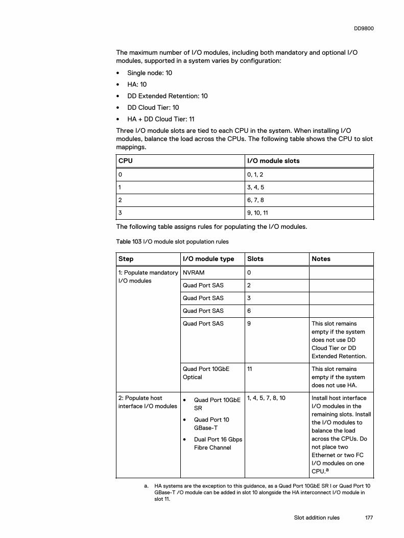
The maximum number of I/O modules, including both mandatory and optional I/Omodules, supported in a system varies by configuration:
l Single node: 10
l HA: 10
l DD Extended Retention: 10
l DD Cloud Tier: 10
l HA + DD Cloud Tier: 11
Three I/O module slots are tied to each CPU in the system. When installing I/Omodules, balance the load across the CPUs. The following table shows the CPU to slotmappings.
CPU I/O module slots
0 0, 1, 2
1 3, 4, 5
2 6, 7, 8
3 9, 10, 11
The following table assigns rules for populating the I/O modules.
Table 103 I/O module slot population rules
Step I/O module type Slots Notes
1: Populate mandatoryI/O modules
NVRAM 0
Quad Port SAS 2
Quad Port SAS 3
Quad Port SAS 6
Quad Port SAS 9 This slot remainsempty if the systemdoes not use DDCloud Tier or DDExtended Retention.
Quad Port 10GbEOptical
11 This slot remainsempty if the systemdoes not use HA.
2: Populate hostinterface I/O modules
l Quad Port 10GbESR
l Quad Port 10GBase-T
l Dual Port 16 GbpsFibre Channel
1, 4, 5, 7, 8, 10 Install host interfaceI/O modules in theremaining slots. Installthe I/O modules tobalance the loadacross the CPUs. Donot place twoEthernet or two FCI/O modules on oneCPU.a
a. HA systems are the exception to this guidance, as a Quad Port 10GbE SR I or Quad Port 10GBase-T /O module can be added in slot 10 alongside the HA interconnect I/O module inslot 11.
DD9800
Slot addition rules 177
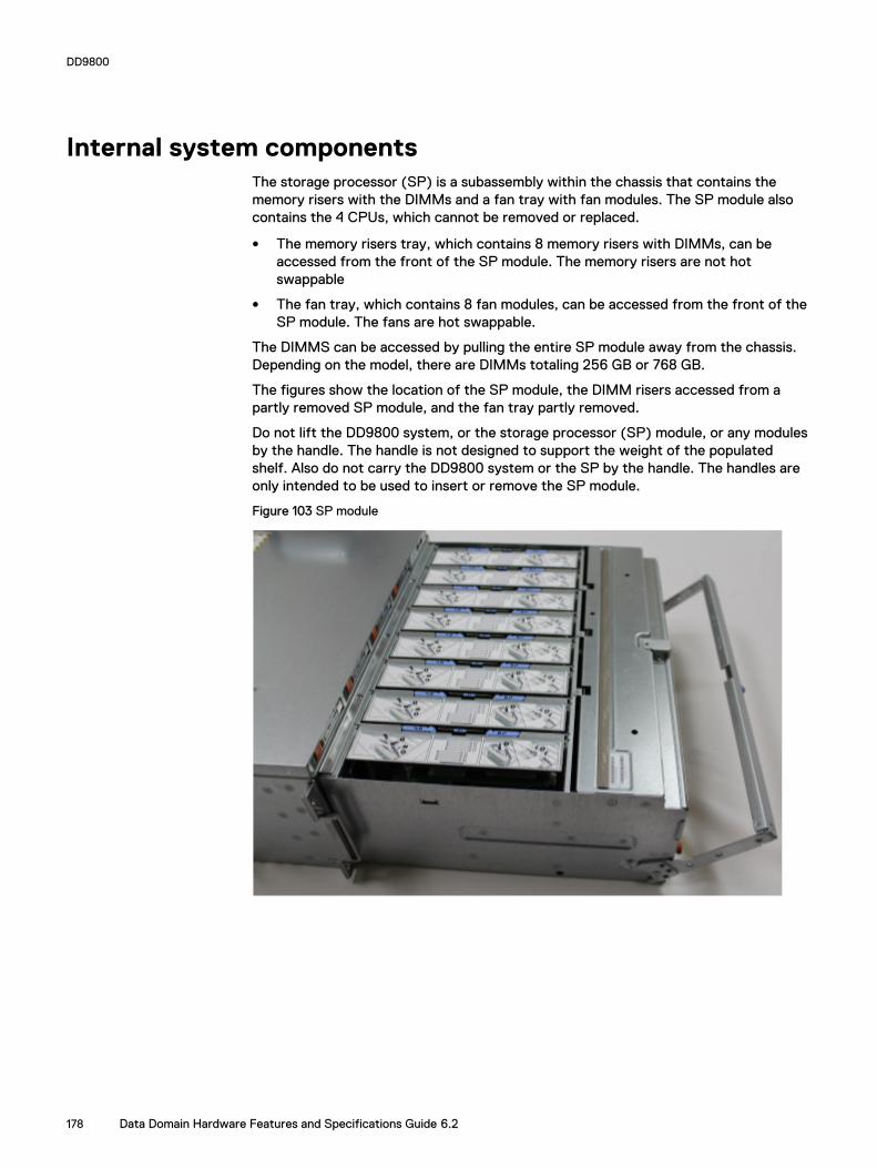
Internal system componentsThe storage processor (SP) is a subassembly within the chassis that contains thememory risers with the DIMMs and a fan tray with fan modules. The SP module alsocontains the 4 CPUs, which cannot be removed or replaced.
l The memory risers tray, which contains 8 memory risers with DIMMs, can beaccessed from the front of the SP module. The memory risers are not hotswappable
l The fan tray, which contains 8 fan modules, can be accessed from the front of theSP module. The fans are hot swappable.
The DIMMS can be accessed by pulling the entire SP module away from the chassis.Depending on the model, there are DIMMs totaling 256 GB or 768 GB.
The figures show the location of the SP module, the DIMM risers accessed from apartly removed SP module, and the fan tray partly removed.
Do not lift the DD9800 system, or the storage processor (SP) module, or any modulesby the handle. The handle is not designed to support the weight of the populatedshelf. Also do not carry the DD9800 system or the SP by the handle. The handles areonly intended to be used to insert or remove the SP module.
Figure 103 SP module
DD9800
178 Data Domain Hardware Features and Specifications Guide 6.2

Figure 104 Releasing a memory riser
1. Left riser card ejector handle2. Release button3. Right riser card ejector handle
Figure 105 Open fan tray
DD9800
Internal system components 179

Note
Do not loosen the blue thumbscrew on the SP latch handle to access the fan tray. Usethe orange thumbscrews on the front as shown in the picture.
1. Left fan tray thumbscrew2. Front panel left handle3. Front panel right handle4. Right fan tray thumbscrew5. Location map of the fans
DIMM modulesThe DD9800 system contains the following memory configurations:
Table 104 DD9800 memory configurations
System Base Expanded ER/DD Cloud Tier
DD9800 32 x 8 GB DIMMs(256 GB)
32 x 8 GB DIMMs+ 32 x 16 GB DIMMS(768 GB)
32 x 8 GB DIMMs+ 32 x 16 GB DIMMS(768 GB)
Cooling fansA system contains eight hot-swappable cooling fans in a 7+1 redundant configuration,which is located in the front of the system within a movable fan tray. The fans providecooling for the processors, DIMMs, and I/O modules. Each fan has an LED whichglows amber when the fan is failed or faulted. A system can run with one fan faulted.
DD9800
180 Data Domain Hardware Features and Specifications Guide 6.2

CHAPTER 12
ES30
l ES30 overview..................................................................................................182l ES30 site requirements.....................................................................................182l ES30 hardware specifications...........................................................................183l Front panel....................................................................................................... 184l Back panel........................................................................................................ 185l Ports.................................................................................................................188
ES30 181

ES30 overviewAdding ES30 expansion shelves to a Data Domain system increases the system'sstorage capacity.
The expansion shelves are organized by sets (or chains). The following table showsthe number of ES30 shelves than can be in a set.
Table 105 ES30 shelves in a set
Configuration ES30 shelves
Base Data Domain systems 1–4
Extended Retention software option 1–7
For redundancy, a shelf set is usually connected to two separate SAS I/O modules orHBA cards on the Data Domain controller, and all of the shelves within a set areconnected to each other via dual paths.
ES30 site requirementsThis table lists the ES30 site requirements.
Table 106 ES30 site requirements
Requirement ES30 expansion shelf
Vertical Space in Standard 19", 4-post Rack 3U. Do not use a two-post rack. See the sliderail and installation documentation in thepackaging for installing in a rack.
Air Conditioning Air conditioning that can cope with themaximum BTU/hr thermal rating.
Temperature Controls Adequate temperature control with a gradient(change) not to exceed 30° C in an hour.
Front Bezel Clearance 1.56 inches (4.0 cm) of unobstructedclearance.
Back Panel Clearance 5 inches (12.7 cm) of unobstructed clearance.
Airflow In a closed or multi-unit rack, ensure that theunit has adequate airflow. If the equipment ismounted in an enclosed (as opposed to afour-post open rack), the front and rear doorsshould have 65% minimum open area forairflow. Whether in an open or enclosed rack,use filler panels to prevent hot airrecirculation. The rack design and installationshould take into consideration the maximumambient operating temperature of theequipment, which is 35° C.
Power/ Grounding Two single-phase AC power outlets with anearth ground conductor (safety ground). Asafe electrical earth connection must be
ES30
182 Data Domain Hardware Features and Specifications Guide 6.2

Table 106 ES30 site requirements (continued)
Requirement ES30 expansion shelf
provided to each power cord. Voltage shouldbe 100-120 VAC or 200-240 VAC; 50 or 60Hz. Use only with branch circuits protectedby a minimum 15A overcurrent protector. Plugthe two power cords into separate branchcircuit supplies for redundancy.
ES30 hardware specifications
Note
All ratings assume a fully configured ES30.
Table 107 ES30 hardware specifications
Specification Description
AC line voltage 100 to 240 Vac ± 10%, single-phase, 47 to 63Hz
AC line current (operating maximum) 2.8 A max at 100 Vac, 1.4 A max at 200 Vac
Power consumption (operating maximum) 280 VA (235 W) max
Power factor 0.98 min at full load, low voltage
Heat dissipation (operating maximum) 8.46 x 10⁵ J/hr, (800 Btu/hr) max
Dimensions (rack mounted, with bezel) l Width: 17.62" (45 cm) Depth: 14”(35.56cm)
l Height: 5.25” (13.34cm) 3 RU
Maximum Weight 68 lbs (30.8 kg)
Operating Temperature l Ambient temperature: 10o C to 35o C (50o
F to 95o F)
l Temperature gradient: 10o C/hr (180o
F/hr)
l Relative humidity extremes: 20% to 80%noncondensing
Recommended Operating Relative Humidity 40% to 55% noncondensing
Non-Operating Temperature l Ambient temperature: -40o C to 65o C(-40o F to 149o F)
l Temperature gradient: 25o C/hr(45oF/hr)
l Relative humidity: 10% to 90%noncondensing
ES30
ES30 hardware specifications 183

Front panelAfter you unlock and remove the snap-on bezel on the front panel, the 15 disks arevisible. Disk numbers, as reported by system commands, range from 1 to 15. Whenfacing the front panel, Disk 1 is located in the leftmost slot in the enclosure and Disk 15in the rightmost slot.
Figure 106 ES30 front panel (bezel removed)
Note
The flanges or sheet metal on the ES30 show 0 to 14 but the software will refer to thelogical numbering of 1 to 15.
Each disk in the enclosure has two LEDs. The disk’s active LED glows green when thedisk is functional. The disk fault LED glows amber when the disk has failed.
If there is a problem with the enclosure, the enclosure fault light is amber. The diskenclosure power light should be on (blue) when the shelf is powered on.
When replacing disks, a good practice is to run this command:
disk beacon <enclosure-id>.<disk-id>
Note
The disk beacon command causes the LED that signals normal operation to flash onthe target disk. Enter Ctrl-C to stop the flash. You can also use the enclosurebeacon command to check the LED to blink on every disk.
Figure 107 Front panel LEDs
ES30
184 Data Domain Hardware Features and Specifications Guide 6.2

1. Disk enclosure fault light2. Disk enclosure power light3. Disk active light4. Disk fault light
Table 108 Status lights visible from front of disk enclosure
Light Quantity Color Meaning
Disk enclosurefault light
1 Amber On when any fault condition exists; if the faultis not obvious from a disk module light, look atthe back of the disk enclosure.
Disk enclosurepower light
1 Blue Power to enclosure is on.
Disk active light 1 per diskmodule
Green No LED when the slot is empty or has a fillermodule. Also, off when the disk is powereddown by command; for example, the result ofa temperature fault.Fast blinking when the SATA/SAS drive ispowered up but not spinning; this is a normalpart of the spin-up sequence, occurringduring the spin-up delays of a slot.
On when the drive has power but is nothanding any I/O activity (the ready state.
Slow blinking when the drive is spinning andhandling I/O activity.
Disk fault light 1 per diskmodule
Amber On when the disk module is faulty, or as anindication to replace the drive.
Back panelFor redundancy, the shelf has two identical power supply/cooling modules and twoidentical shelf controllers which are placed in reverse order.
Note
When replacing a component, note its orientation before removing it. Insert thereplacement in the same position.
Power supply A and controller A are located at the bottom of the chassis, and powersupply B and controller B are located at the top of the chassis.
ES30
Back panel 185

Figure 108 Back panel: Power modules and controllers
1. LEDs
l Power supply B: Power LED
l Power fault: Amber
l Blower fault: Amber
2. Expansion (Out)
3. Host (In)
4. Enclosure address (not used)
5. Power (Green) or Fault (Amber)
6. Bus ID (not used)
7. Host link active
8. Expansion link active
9. LEDs
l Power supply A Power LED
l Power fault: Amber
l Blower fault: Amber
ES30
186 Data Domain Hardware Features and Specifications Guide 6.2

Figure 109 Power Supply A LEDs
Each shelf controller has two SAS ports. The port labeled with a circle symbol is theHost port, and the port labeled with a diamond symbol is the Expansion port. TheExpansion ports are located on the outside, and the Host ports on the inside (reversedcontroller positions).
Table 109 Status lights visible from rear of disk enclosure
Light Quantity Color Meaning
ControllerPower
1 per Controller Blue or Green On when the Controller is powered on.Blue when host connection is active at thenormal speed for DD990, DD2500,DD4200, DD4500, DD6300, DD6800,DD7200, DD9300, DD9500, and DD9800systems.
Green when host connection is slow forthose systems or at normal speed for allother systems.
Blue when host connection is active at thenormal speed.
Green when host connection is slow.
Controller Fault 1 per Controller Amber On when either the Controller or a SASconnection is faulty. On during power-onself-test
Host Link Active 1 per Controller Blue On when the host connection is active.
Expansion LinkActive
1 per Controller Blue On when the expansion connection isactive.
Power SupplyActive
1 per powersupply
Green On when the power supply is operating.
Power SupplyFault*
1 per powersupply
Amber On when the power supply is faulty or isnot receiving AC line voltage.
ES30
Back panel 187

Table 109 Status lights visible from rear of disk enclosure (continued)
Light Quantity Color Meaning
Flashing when either a multiple blower orambient over temperature condition hasshut off DC power to the system.
Blower Fault* 1 per powersupply
Amber On when one of the blowers in the powersupply is faulty.
*The ES30 and FS15 continue to run with a single power supply and three of its fourblowers. Removing a power/cooling module constitutes a multiple blower faultcondition, and powers down the shelf unless you replace a module within two minutes.
PortsDepending on the model, a Data Domain system has one to four dual- or quad-portSAS HBA cards or SAS I/O modules installed. The ES30 shelf has two controllers (Blocated above A). Each controller has two ports, a host and an expansion port.
See #unique_137 for SAS HBA card, SAS I/O module, and port locations.
ES30
188 Data Domain Hardware Features and Specifications Guide 6.2

CHAPTER 13
DS60
l DS60 overview................................................................................................. 190l DS60 site requirements.................................................................................... 190l DS60 hardware specifications........................................................................... 191l DS60 front panel ............................................................................................. 192l Back panel........................................................................................................ 193l Disk enclosure interior ..................................................................................... 194l Expansion shelf cables...................................................................................... 197l Ports.................................................................................................................198
DS60 189

DS60 overviewAdding DS60 expansion shelves to a Data Domain system increases the system'sstorage capacity.
The expansion shelves are organized by sets (or chains). The following table showsthe number of DS60 shelves in set (chain) each system can support.
Table 110 DS60 shelf set support
System (base) DS60 shelves
DD4200, DD4500, and DD7200 2 per set (chain)
DD6300 1 shelf only*
DD6800, DD9300, DD9500, and DD9800 4 per set (chain)
* DD6300 systems only supports the addition of one DS60 expansion shelf.
DS60 site requirementsThis table lists the DS60 site requirements. See DS60 hardware specifications on page191 for hardware specifications information.
Table 111 Site requirements
Requirement DS60 Expansion Shelf
Vertical space in standard 19", 4-post rack 5U including a 1U Cable Managements Tray.Do not use a two-post rack. See the slide railand installation documentation in thepackaging for installing in a rack.
Air conditioning Air conditioning that can cope with themaximum BTU/hr thermal rating.
Temperature controls Adequate temperature control with a gradient(change) not to exceed 30° C in an hour.
Front bezel clearance 1.56 inches (4.0 cm) of unobstructedclearance.
Back panel clearance 5 inches (12.7 cm) of unobstructed clearance.
Airflow In a closed or multi-unit rack, ensure that theunit has adequate airflow. If the equipment ismounted in an enclosed (as opposed to afour-post open rack), the front and rear doorsshould have 65% minimum open area forairflow. Whether in an open or enclosed rack,use filler panels to prevent hot air re-circulation. The rack design and installationshould take into consideration the maximumambient operating temperature of theequipment, which is 35° C.
DS60
190 Data Domain Hardware Features and Specifications Guide 6.2

Table 111 Site requirements (continued)
Requirement DS60 Expansion Shelf
Power/grounding The Power distribution within the rack shouldprovide a safe electrical earth connection.Voltage should be 200-240 VAC; 50 or 60 Hz.Plug four power cords - two from each powersupply into separate branch circuit suppliesfor redundancy—one set of cords from onepower supply goes to one branch and thesecond set of cords from the other powersupply goes to a different branch. Eachreceptacle must be capable of safelysupplying 0.94 amps from each power socketor 1.87 amps from each socket in case of aredundant circuit.
DS60 hardware specifications
Note
All ratings assume a fully configured DS60 shelves.
Table 112 Hardware specifications
Specification Description
AC line voltage 200 to 240 Vac ± 10%, single-phase, 47 to 63Hz
AC line current (operating maximum) 4.9 A max at 200 Vac
Power consumption (operating maximum) 980 VA (931W) max
Power factor 0.95 min at full load, low voltage
Heat dissipation (operating maximum) 3.36 x 10⁶ J/hr, (3177 Btu/hr) max
Dimensions (rack mounted) l Height: 8.75 in (22.23 cm) 5U (4U plus 1Ucable management tray).
l Width including rails: 17.50 in (44.45 cm)
l Depth (chassis only): 34.5 in (87.63 cm)
l Maximum depth (fully configured): 36.4in (92.46 cm)
Shelf weight l Without FRUs installed: 55.0 lb ( 24.7 kg)
l With FRUs installed: 225.0 lb (102 kg)
Operating temperature l Ambient temperature: 41o F to 104o F (5o
C to 40o C)
l Temperature gradient: 18o F/hr (10o
C/hr)
DS60
DS60 hardware specifications 191

Table 112 Hardware specifications (continued)
Specification Description
l Relative humidity extremes: 20% to 80%noncondensing
Recommended operating relative humidity 40% to 55% noncondensing
Operating elevation -50 to 7500 ft (-16 to 2300 m)
Non-operating (shipping and storage)temperature
l Ambient temperature: -40o F to 149o F(-40o C to 65o F)
l Temperature gradient: 45o F/hr(25oC/hr)
l Relative humidity: 10% to 90%noncondensing
l Elevation: -50 to 35,000 ft (-16 to 10,600m)
DS60 front panelFigure 110 DS60 front panel
Note
The front LEDs are identified inside the red rectangle.
If there is a problem with the enclosure, the enclosure fault light LED (marked with atriangle with an exclamation mark) is amber. When the shelf is powered on and active,the disk enclosure power LED (marked with a circle with a vertical line) is blue.
Table 113 LED status lights
Light Quantity Color Meaning
Disk Enclosure Power 1 Blue Power to enclosure ison.
Disk Enclosure Fault 1 Amber On when any faultcondition exists; if the
DS60
192 Data Domain Hardware Features and Specifications Guide 6.2

Table 113 LED status lights (continued)
Light Quantity Color Meaning
fault is not obviousfrom a disk or fanmodule light, look atthe back of the diskenclosure.
Note
The individual disk LEDs are only visible when the disk enclosure is opened to verifythe disks inside.
For part replacement information, refer to the DS60 Expansion Shelf Installation andFRU Replacement Guide.
Back panelThe back panel has two dual power supplies and two LCCs (Link Controller Cards).
Figure 111 DS60 back panel
Each controller has 4 SAS ports (laid out as 2 pairs). Standard Data Domain systems,and systems with the licensed HA feature only use ports 0 and 2 on each controller.Ports 1 and 3 typically have a plastic plug blocking the unused ports to make insertinga cable into the correct ports easier.
Table 114 Status lights visible from rear of disk enclosure
Light Quantity Color Meaning
Controllerpower
1 per controller Green On when the Controller is powered on.
Controller fault 1 per controller Amber On when either the Controller or a SASconnection is faulty. On during power-onself test.
Link active 4 per controller Blue On when the host connection is active.
Power supplyinput voltage
1 per powersupply
Green Input power green when it is working.
DS60
Back panel 193

Table 114 Status lights visible from rear of disk enclosure (continued)
Light Quantity Color Meaning
Power supplyfault*
1 per powersupply
Amber l On when the power supply is faulty oris not receiving AC line voltage.
l Flashing when either a multiple bloweror ambient over temperature conditionhas shut off DC power to the system.
The DS60 continues to run with a single power supply and two fans (out of the threefans).
For part replacement information, refer to the DS60 Installation and FRU ReplacementGuide.
Disk enclosure interiorThe disks are visible when the DS60 is pulled out of the rack and the top cover isremoved from the chassis. There are also three fans in the front of the disk enclosureand each fan has a fault LED.
Each disk in the enclosure has two LEDs. The active LED glows blue when the disk isfunctional. The disk fault LED glows amber when the disk has failed.
Note
The individual disk and fan LEDs are only visible when the disk enclosure is opened toverify the disks inside.
Figure 112 Fans and disk drives inside the disk enclosure
DS60
194 Data Domain Hardware Features and Specifications Guide 6.2

Table 115 LED status lights
Light Quantity Color Meaning
Disk Active
Note
Only visible after thedisk enclosure isopened.
1 per disk module Blue l No LED when theslot is empty orhas a fillermodule. Also, offwhen the disk ispowered down bycommand; forexample, theresult of atemperaturefault.
l Fast blinkingwhen the SASdrive is poweredup but notspinning; this is anormal part of thespin-upsequence,occurring duringthe spin-updelays of a slot.
l On when thedrive has powerbut is not handingany I/O activity(the ready state).
l Disk and fanlights are onlyavailable whenenclosure isremoved from thechassis.
l Slow blinkingwhen the drive isspinning andhandling I/Oactivity.
Disk Fault
Note
Only visible after thedisk enclosure isopened.
1 per disk module Amber On when the diskmodule is faulty, or asan indication toreplace the drive.
Fan fault 1 per fan module Amber On when the fanmodule is faulty, or as
DS60
Disk enclosure interior 195

Table 115 LED status lights (continued)
Light Quantity Color Meaning
an indication toreplace the fan.
The DD OS software manages the drives in packs (groups) of 15. A top down view ofthe chassis shows that the disks are arranged in four packs (groups) of 15 drives. Thepacks are color coded—pack 1 purple, pack 2 is yellow, pack 3 is green, and pack 4 ispink. A pack must have the same size drives. Pack 1 is shown within the red rectangle.
Figure 113 Drives as packs
The next table shows how the drives are distributed by packs (groups) and numberedphysically. The bottom of the table represents the front of the shelf
Table 116 Physical drives
Rows Pack 1 Pack 2 Pack 3 Pack 4
E 0-2 3-5 6-8 9-11
D 0-2 3-5 6-8 9-11
DS60
196 Data Domain Hardware Features and Specifications Guide 6.2

Table 116 Physical drives (continued)
Rows Pack 1 Pack 2 Pack 3 Pack 4
C 0-2 3-5 6-8 9-11
B 0-2 3-5 6-8 9-11
A 0-2 3-5 6-8 9-11
Although the disk numbers are physically 0 to 59, the disks are reported logically bysystem software commands in two ways:
l A range from 1 to 60, usually reported with the enclosure number (e.g. 3.37)
l The position matrix A-E (1-12)
For part replacement information, refer to the DS60 Expansion Shelf Installation andFRU Replacement Guide.
Expansion shelf cablesExpansion shelves are connected to each other and to the Data Domain controller withqualified cables. The expansion shelf can be connected to supported Data Domainsystems only by using SAS (serial-attached SCSI) cables. A Data Domain shelf withqualified disks can be added as an expansion shelf if there are complete drive packs(15 in a pack) in the correct position.
Note
Shelves for other Dell EMC product lines look identical. Check the product numberswhen unpacking.
DS60 cablesThe DS60 shelves use cables with HD-mini-SAS connectors at both ends to connectthe shelves to the controllers that have SAS I/O modules, such as DD4200, DD4500,DD6300, DD6800, DD7200, DD9300, DD9500, and DD9800 systems.
The DS60 connector is referred as the HD-mini-SAS connector and is same as the I/Omodule connectors. These cables are available in 3M, 4M, and 5M lengths.
Use the appropriate length for the connection you are making. Refer to the specificInstallation and Configuration Guide of the shelves for the recommended cablelengths:
l Use the 3-meter cable in the same rack either to connect to a controller or shelf toadjacent shelf.
l Use a 3-meter, 4-meter, or 5-meter cable when a DS60 is in another rack.
DS60
Expansion shelf cables 197

Figure 114 HD-mini-SAS connector
Table 117 HD-mini-SAS to mini-SAS cable part numbers
Cable Part Number Cable Length
038-004-380-01 3M(118 in.)
038-000-212-00 4M (158 in.)
038-000-214-00 5M (196 in.)
Special cables must be used when attaching an ES30 to a chain with a DS60.Specifically, one HOST (circle) connection and one EXPANSION (diamond) cables areconnected between the ES30 LCC and the DS60 LCC connection. Since this is not acommon situation, only two expansion cable lengths are available.
Table 118 HD-mini-SAS to ES30 host and ES30 expansion port cable part numbers
Cable Part Number Cable Type Cable Length
038-003-810 Host 2M (78 in.)
038-003-813 Host 5M (196 in.)
038-004-108 Expansion 2M (78 in.)
038-004-111 Expansion 5M (196 in.)
The cable connectors must be secured with their latch assembly.
PortsDepending on the model, a Data Domain system has two to four quad-port SAS IOmodules installed. The DS60 shelf has two controllers. Each DS60 controller has fourports, labeled 0, 1, 2, and 3 (right to left).
DS60
198 Data Domain Hardware Features and Specifications Guide 6.2

CHAPTER 14
FS15
l Overview of FS15 SSD drives...........................................................................200l Site requirements.............................................................................................200l FS15 hardware specifications........................................................................... 201l FS15 front panel...............................................................................................202l Back panel........................................................................................................204l Status LEDs..................................................................................................... 206
FS15 199

Overview of FS15 SSD drivesThe FS15 is an external shelf consisting of a specific number of SSD drives, dependingupon the Data Domain system, and are used to cache meta-data.
The SSDs for the FS15 shelf are 800GB 3WPD devices, which have positiveperformance and longevity characteristics.
Table 119 Number of SSD drives and Data Domain model compatibilty
Number of Drives Model
2 DD6800 with HA
5 l DD6800 with HA
l DD9300 with HA
8 l DD9500 - with or without HA
l DD9300with HA
15 DD9500 - with or without HA
Note
Unused drive slots have drive fillers to improve airflow.
There are also upgrade kits available to add more SSDs if a Data Domain system isexpanded to have additional memory.
Upgrade Pack Use
3 Drive Upgrade Pack To create a 5 drive shelf from originally a 2drive shelf or an 8 drive shelf from originally a5 drive shelf
7 Drive Upgrade Pack To create a 15 drive shelf from an 8 drive shelf
Site requirementsThis table lists the FS15 site requirements.
Table 120 FS15 site requirements
Requirement FS15 shelf
Vertical Space inStandard 19", 4-postRack
3U. Do not use a two-post rack. See the slide rail and installationdocumentation in the packaging for installing in a rack.
Air Conditioning Air conditioning that can cope with the maximum BTU/hr thermalrating.
TemperatureControls
Adequate temperature control with a gradient (change) not to exceed30° C in an hour.
FS15
200 Data Domain Hardware Features and Specifications Guide 6.2

Table 120 FS15 site requirements (continued)
Requirement FS15 shelf
Front BezelClearance
1.56 inches (4.0 cm) of unobstructed clearance.
Back PanelClearance
5 inches (12.7 cm) of unobstructed clearance.
Airflow In a closed or multi-unit rack, ensure that the unit has adequate airflow.If the equipment is mounted in an enclosed (as opposed to a four-postopen rack), the front and rear doors should have 65% minimum openarea for airflow. Whether in an open or enclosed rack, use filler panelsto prevent hot air recirculation. The rack design and installation shouldtake into consideration the maximum ambient operating temperature ofthe equipment, which is 35° C.
Power/ Grounding Two single-phase AC power outlets with an earth ground conductor(safety ground). A safe electrical earth connection must be provided toeach power cord. Voltage should be 100-120 VAC or 200-240 VAC; 50or 60 Hz. Use only with branch circuits protected by a minimum 15Aovercurrent protector. Plug the two power cords into separate branchcircuit supplies for redundancy.
FS15 hardware specifications
Note
All ratings assume a fully configured FS15.
Table 121 FS15 hardware specifications
Specification Description
AC line voltage 100 to 240 Vac ± 10%, single-phase, 47 to 63Hz
AC line current (operating maximum) 2.8 A max at 100 Vac, 1.4 A max at 200 Vac
Power consumption (operating maximum) 280 VA (235 W) max
Power factor 0.98 min at full load, low voltage
Heat dissipation (operating maximum) 8.46 x 10⁵ J/hr, (800 Btu/hr) max
Dimensions (rack mounted, with bezel) l Width: 17.62" (45 cm) Depth: 14”(35.56cm)
l Height: 5.25” (13.34cm) 3 RU
Maximum Weight 68 lbs (30.8 kg)
Operating Temperature l Ambient temperature: 10o C to 35o C (50o
F to 95o F)
l Temperature gradient: 10o C/hr (180o
F/hr)
FS15
FS15 hardware specifications 201

Table 121 FS15 hardware specifications (continued)
Specification Description
l Relative humidity extremes: 20% to 80%noncondensing
Recommended Operating Relative Humidity 40% to 55% noncondensing
Non-Operating Temperature l Ambient temperature: -40o C to 65o C(-40o F to 149o F)
l Temperature gradient: 25o C/hr(45oF/hr)
l Relative humidity: 10% to 90%noncondensing
FS15 front panelAfter you unlock and remove the snap-on bezel on the front panel, the 15 disks arevisible. Disk numbers, as reported by system commands, range from 1 to 15. Whenfacing the front panel, Disk 1 is located in the leftmost slot in the enclosure and Disk 15in the rightmost slot.
Figure 115 FS15 front panel (bezel removed)
Note
The flanges or sheet metal on the FS15 show 0 to 14 but the software will refer to thelogical numbering of 1 to 15.
Each disk in the enclosure has two LEDs. The disk’s active LED glows green when thedisk is functional. The disk fault LED glows amber when the disk has failed.
If there is a problem with the enclosure, the enclosure fault light is amber. The diskenclosure power light should be on (blue) when the shelf is powered on.
When replacing FS15 disks, a good practice is to run this command:
disk beacon <enclosure-id>.<disk-id>
Note
The disk beacon command causes the LED that signals normal operation to flash onthe target disk. Enter Ctrl-C to stop the flash. You can also use the enclosurebeacon command to check the LED to blink on every disk.
FS15
202 Data Domain Hardware Features and Specifications Guide 6.2

Figure 116 Front panel LEDs
1. Disk enclosure fault light2. Disk enclosure power light3. Disk active light4. Disk fault light
Table 122 Status lights visible from front of disk enclosure
Light Quantity Color Meaning
Disk enclosurefault light
1 Amber On when any fault condition exists; if the faultis not obvious from a disk module light, look atthe back of the disk enclosure.
Disk enclosurepower light
1 Blue Power to enclosure is on.
Disk active light 1 per diskmodule
Green No LED when the slot is empty or has a fillermodule. Also, off when the disk is powereddown by command; for example, the result ofa temperature fault.Fast blinking when the SATA/SAS drive ispowered up but not spinning; this is a normalpart of the spin-up sequence, occurringduring the spin-up delays of a slot.
On when the drive has power but is nothanding any I/O activity (the ready state.
Slow blinking when the drive is spinning andhandling I/O activity.
Disk fault light 1 per diskmodule
Amber On when the disk module is faulty, or as anindication to replace the drive.
FS15
FS15 front panel 203

Back panelFor redundancy, the shelf has two identical power supply/cooling modules and twoidentical shelf controllers which are placed in reverse order.
Note
When replacing a component, note its orientation before removing it. Insert thereplacement in the same position.
Power supply A and controller A are located at the bottom of the chassis, and powersupply B and controller B are located at the top of the chassis.
Figure 117 Back panel: Power modules and controllers
1. LEDs
l Power supply B: Power LED
l Power fault: Amber
l Blower fault: Amber
2. Expansion (Out)
3. Host (In)
4. Enclosure address (not used)
5. Power (Green) or Fault (Amber)
6. Bus ID (not used)
7. Host link active
8. Expansion link active
9. LEDs
l Power supply A Power LED
l Power fault: Amber
l Blower fault: Amber
FS15
204 Data Domain Hardware Features and Specifications Guide 6.2
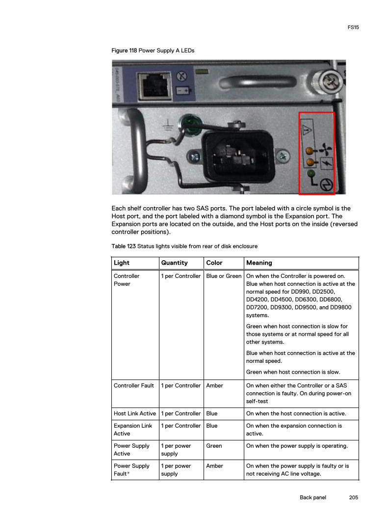
Figure 118 Power Supply A LEDs
Each shelf controller has two SAS ports. The port labeled with a circle symbol is theHost port, and the port labeled with a diamond symbol is the Expansion port. TheExpansion ports are located on the outside, and the Host ports on the inside (reversedcontroller positions).
Table 123 Status lights visible from rear of disk enclosure
Light Quantity Color Meaning
ControllerPower
1 per Controller Blue or Green On when the Controller is powered on.Blue when host connection is active at thenormal speed for DD990, DD2500,DD4200, DD4500, DD6300, DD6800,DD7200, DD9300, DD9500, and DD9800systems.
Green when host connection is slow forthose systems or at normal speed for allother systems.
Blue when host connection is active at thenormal speed.
Green when host connection is slow.
Controller Fault 1 per Controller Amber On when either the Controller or a SASconnection is faulty. On during power-onself-test
Host Link Active 1 per Controller Blue On when the host connection is active.
Expansion LinkActive
1 per Controller Blue On when the expansion connection isactive.
Power SupplyActive
1 per powersupply
Green On when the power supply is operating.
Power SupplyFault*
1 per powersupply
Amber On when the power supply is faulty or isnot receiving AC line voltage.
FS15
Back panel 205

Table 123 Status lights visible from rear of disk enclosure (continued)
Light Quantity Color Meaning
Flashing when either a multiple blower orambient over temperature condition hasshut off DC power to the system.
Blower Fault* 1 per powersupply
Amber On when one of the blowers in the powersupply is faulty.
*The ES30 and FS15 continue to run with a single power supply and three of its fourblowers. Removing a power/cooling module constitutes a multiple blower faultcondition, and powers down the shelf unless you replace a module within two minutes.
Status LEDsVerify the status of the by checking the LEDs. Controller B is located above ControllerA in the center of the rear panel. The power supply/cooling units are above and belowthe controllers.
Facing the back panel of the FS15, the Expander ports are the outer of the two ports;the Host ports are the inner of the two ports. The ports are identified by symbols onthe rear panel: a circle symbol indicates a Host port; a diamond symbol indicates anExpander port.
Figure 119 Rear panel overview
Table 124 Status LEDs
Light Quantity Color Meaning
Controller power 1 per controller Green On when thecontroller is poweredon
Controller failure 1 per controller Amber On when either thecontroller or a SASconnection has failed.On during a power-onself test.
Host link active 1 per controller Blue On when the hostconnection is active
FS15
206 Data Domain Hardware Features and Specifications Guide 6.2

Table 124 Status LEDs (continued)
Light Quantity Color Meaning
Expansion link active 1 per controller Blue On when theexpansion host isactive
FS15
Status LEDs 207

FS15
208 Data Domain Hardware Features and Specifications Guide 6.2