Data Center Disaster Recovery - · PDF file©2006 Cisco Systems, Inc. All rights reserved....
63
© 2006 Cisco Systems, Inc. All rights reserved. Cisco Confidential Presentation_ID 1 Data Center Disaster Recovery KwaiSeng Consulting Systems Engineer
Transcript of Data Center Disaster Recovery - · PDF file©2006 Cisco Systems, Inc. All rights reserved....

© 2006 Cisco Systems, Inc. All rights reserved. Cisco ConfidentialPresentation_ID 1
Data Center Disaster Recovery
KwaiSeng
Consulting Systems Engineer

© 2006 Cisco Systems, Inc. All rights reserved. 2
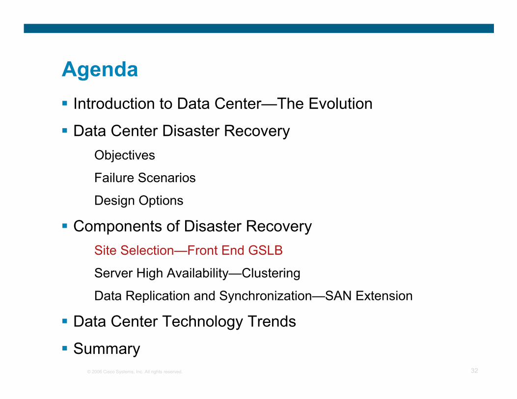
Agenda
� Data Center—The Evolution
� Data Center Disaster Recovery
Objectives
Failure Scenarios
Design Options
� Components of Disaster Recovery
Site Selection—Front End GSLB
Server High Availability—Clustering
Data Replication and Synchronization—SAN Extension
� Data Center Technology Trends
� Summary

© 2006 Cisco Systems, Inc. All rights reserved. 3
The Evolution of Data Centers

© 2006 Cisco Systems, Inc. All rights reserved. 4
Data Center Evolution
1960 1980 2000 2010
Business Agility
Networked Data Center Phase
Mainframes
Terminal
Client/Server
Compute Evolution
Network Evolution
Network
OptimizationInternet
Computing
Content Networking
Data Center Continuous Availability
Data Center Consolidation
Data Center
Virtualization
TCP/IP
Thin Client: HTTP
1. Consolidation
2. Integration
3. Virtualization
4. High Availability
Data CenterNetworking

© 2006 Cisco Systems, Inc. All rights reserved. 5
N-Tier Applications
DB Servers
App Servers
Web Servers
Mainframe OperationsIP Comm.
Front End Network
Application/Server Optimization
ContentSwitch
Cache
Today’s Data Center Integration of Many Systems and Services
TapeFC SAN
RAID
Storage Network
NAS
FCSwitch
VSANs
Scalable Infrastructure
DC Storage NetworksDistributed Data Centers
Application and Server Optimization
Data Center Security
Security
Firewall
IDS
Resilient IP
Metro NetworkDWDM/SONET/Ethernet
FCSwitch
Secondary Data Center
MAN/Internet
DR Data Center
FCSwitch
WAN/Internet

© 2006 Cisco Systems, Inc. All rights reserved. 6
PrimaryData Center
SecondaryData Center
App A App B App A App C
FC FC
What Is Distributed Data Center?
Data Replication

© 2006 Cisco Systems, Inc. All rights reserved. 7
Distributed Data Centers
� Required by disaster recovery and business continuance
� Avoid single, concentrated data depositary
� High availability of applications and data access
� Load balancing together with performance scalability
� Better response and optimal content routing: proximityto clients

© 2006 Cisco Systems, Inc. All rights reserved. 8
PrimaryData Center
SecondaryData Center
App A App B App A App C
FC FC
Front-End IP Access Layer
“Content Routing”Site Selection
© 2006 Cisco Systems, Inc. All rights reserved. 9
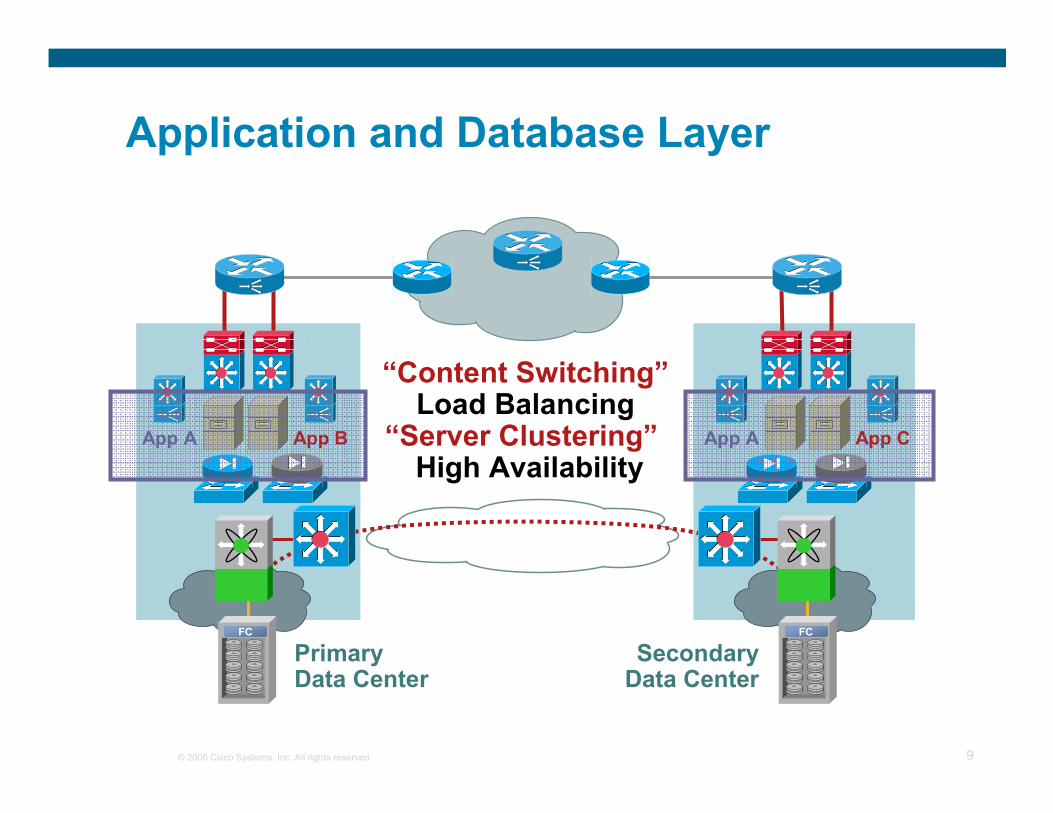
PrimaryData Center
SecondaryData Center
App A App B App A App C
FC FC
Application and Database Layer
“Content Switching”Load Balancing
“Server Clustering”High Availability

© 2006 Cisco Systems, Inc. All rights reserved. 10
PrimaryData Center
SecondaryData Center
App A App B App A App C
FC FC
Backend SAN Extension
“Storage” and “Optical”Data Replicationand Transporting

© 2006 Cisco Systems, Inc. All rights reserved. 11
Data Center Disaster Recovery

© 2006 Cisco Systems, Inc. All rights reserved. 12
Agenda
� Introduction to Data Center—The Evolution
� Data Center Disaster Recovery
Objectives
Failure Scenarios
Design Options
� Components of Disaster Recovery
Site Selection—Front End GSLB
Server High Availability—Clustering
Data Replication and Synchronization—San Extension
� Data Center Technology Trends
� Summary

© 2006 Cisco Systems, Inc. All rights reserved. 13
Disaster Recovery
� Recovery of data and resumption of service—Ensuring business can recover and continue after failure or disaster
� Ability of a business to adapt, change and continue when confronted with various outside impacts
� Mitigating the impact of a disaster

© 2006 Cisco Systems, Inc. All rights reserved. 14
Disaster RecoveryWhat It Means for Business
Zero Down Time Is the Ultimate Goal
Business Resilience
Continued Operation ofBusiness During a Failure
Disaster Recovery
Protecting Data Through Offsite Data Replication and Backup
Business Continuance
Restoration of Business After a Failure

© 2006 Cisco Systems, Inc. All rights reserved. 15
Disaster Recovery Planning
� Business Impact Analysis (BIA)
Determines the impacts of various disasters to specific businessfunctions and company assets
� Risk analysis
Identifies important functions and assets that are critical to company’s operations
� Disaster Recovery Plan (DRP)
Restores operability of the target systems, applications,or computing facility at the secondary data center after the disaster

© 2006 Cisco Systems, Inc. All rights reserved. 16
Disaster Recovery Objectives
� Recovery Point Objective (RPO)
The point in time (prior to the outage) in which system and data must be restored to
Tolerable lost of data in event of disaster or failure
The impact of data loss and the cost associated with the loss
� Recovery Time Objective (RTO)
The period of time after an outage in which the systems and data must be restored to the predetermined RPO
The maximum tolerable outage time

© 2006 Cisco Systems, Inc. All rights reserved. 17
Recovery Point/Time vs. Cost
� Smaller RPO/RTO
Higher $$$, replication, hot standby
� Larger RPO/RTO
Lower $$$, tape backup/restore, cold standby
Time
DisasterStrikes
Time t1 Time t2
Systems Recoveredand Operational
Recovery Time
ExtendedCluster
ManualMigration
TapeRestore
Secs Mins Hours Days Weeks
$$$ Increasing Cost
Recovery Point
SynchronousReplication
SecsMinsHoursDays
AsynchronousReplication
PeriodicReplication
Tapebackup
time t0
$$$ Increasing Cost
Critical Data Is Recovered

© 2006 Cisco Systems, Inc. All rights reserved. 18
Agenda
� Introduction to Data Center—The Evolution
� Data Center Disaster Recovery
Objectives
Failure Scenarios
Design Options
� Components of Disaster Recovery
Site Selection—Front End GSLB
Server High Availability—Clustering
Data Replication and Synchronization—San Extension
� Data Center Technology Trends
� Summary

© 2006 Cisco Systems, Inc. All rights reserved. 19
Failure Scenarios
� Network failure
� Device failure
� Storage failure
� Site failure
Disaster Could Mean Many Types of Failure

© 2006 Cisco Systems, Inc. All rights reserved. 20
InternetService
Provider AService
Provider B
Network Failures
� ISP failure
� Dual ISP connections
� Multiple ISP
� Connection failure within the network
� EtherChannel®
� Multiple route paths

© 2006 Cisco Systems, Inc. All rights reserved. 21
InternetService
Provider AService
Provider B
Device Failures
� Routers, switches, FWs
� HSRP
� VRRP
� Hosts
� HA cluster
� LB server farm
� NIC teaming

© 2006 Cisco Systems, Inc. All rights reserved. 22
InternetService
Provider AService
Provider B
Storage Failures
� Disk arrays
� RAID
� Disk controllers
� Storage Replication
� Site to Site Mirroring
� Optimization

© 2006 Cisco Systems, Inc. All rights reserved. 23
InternetService
Provider AService
Provider B
Site Failures
� Partial site failure
� Application maintenance
� Application migration
� Application scheduled DR exercise
� Complete site failure
� Disaster

© 2006 Cisco Systems, Inc. All rights reserved. 24
Agenda
� Introduction to Data Center—The Evolution
� Data Center Disaster Recovery
Objectives
Failure Scenarios
Design Options
� Components of Disaster Recovery
Site Selection—Front End GSLB
Server High Availability—Clustering
Data Replication and Synchronization—San Extension
� Data Center Technology Trends
� Summary

© 2006 Cisco Systems, Inc. All rights reserved. 25
Warm Standby
� A data center that is equipped with hardware and communications interfaces capable of providing backup operating support
� Latest backups from the production data center must be delivered
� Network access needs to be activated
� Application needs to be manually started

© 2006 Cisco Systems, Inc. All rights reserved. 26
Disaster Recovery—Active/Standby
PrimaryData Center
SecondaryData Center
(Warm Standby)
App A App B App A App C
FC FC
IP/Optical Network

© 2006 Cisco Systems, Inc. All rights reserved. 27
Hot Standby
� A data center that is environmentally ready and has sufficient hardware, software to provide data processing service with little down time
� Hot backup offers disaster recovery, with little or no human intervention
� Application data is replicated from the primary site
� A hot backup site provides better RTO/RPO than warm standby but cost more to implement
� Business continuance

© 2006 Cisco Systems, Inc. All rights reserved. 28
Disaster Recovery—Active/Standby
PrimaryData Center
SecondaryData Center
App A App B App A App C
FC FC
IP/Optical Network

© 2006 Cisco Systems, Inc. All rights reserved. 29
Active/Active DR DesignMultiple Tiers of Application
Presentation Tier
Application Tier
Storage Tier
InternetService
Provider AService
Provider B

© 2006 Cisco Systems, Inc. All rights reserved. 30
InternalNetwork
Active/Active Application Processing
Active/StandbyDatabase Processing
orActive/Active
for Different Application
InternalNetwork
Active/Active Web Hosting
Active/Active Data Centers
InternetService
Provider A
ServiceProvider B
© 2006 Cisco Systems, Inc. All rights reserved. 31
Components of Disaster Recovery
© 2006 Cisco Systems, Inc. All rights reserved. 32
Agenda
� Introduction to Data Center—The Evolution
� Data Center Disaster Recovery
Objectives
Failure Scenarios
Design Options
� Components of Disaster Recovery
Site Selection—Front End GSLB
Server High Availability—Clustering
Data Replication and Synchronization—SAN Extension
� Data Center Technology Trends
� Summary

© 2006 Cisco Systems, Inc. All rights reserved. 33
Site Selection Mechanisms
� Site selection mechanisms depend on the technology or mix of technologies adopted for request routing:
1. HTTP redirect
2. DNS-based
3. L3 Routing with Route Health Injection (RHI)
� Health of servers and/or applications needs to be taken into account
� Optionally, other metrics (like load) can be measured and utilized for a better selection

© 2006 Cisco Systems, Inc. All rights reserved. 34
HTTP Redirection—Traffic Flow
http://www2.cisco.com/
http://www1.cisco.com/
http://www.cisco.com/
1.GET/H
TTP/1
.1
Host: ww
w.cisco.com
2.HTTP/1.1 302 Moved
Location: ww
w2.cisco.com
3. GET/HTTP/1.1Host: www2.cisco.com
HTTP/1.1 200 OK
Keepalives

© 2006 Cisco Systems, Inc. All rights reserved. 35
DNS-Based Site Selection—Traffic Flow
Client
DNS Proxy
Data Center 1
http://www.cisco.com/
Root Name Server for/ Authoritative Name Server for .com
Authoritative Name Servercisco.com
AuthoritativeName Server
www.cisco.com
Keepali
ves
1
2
3 4
56
78
9
10
Keepalives
Data Center 2
UDP:53
TCP:80

© 2006 Cisco Systems, Inc. All rights reserved. 36
Route Health Injection—Implementation
Client BClient ARouter 13
Router 11
Router 12
Router 10
Location BPreferred Location for
VIP x.y.w.z
Location ABackup Location for
VIP x.y.w.z
Very High Cost
Low Cost

© 2006 Cisco Systems, Inc. All rights reserved. 37
Site Selection Summary
Site Persistence
Convergence
Yes
No
NoWithin Secs
DNS Cache
No
YesActive/StandbyRHI
YesActive/ActiveDNS
NoActive/ActiveHTTP
Re-Direct
App Health Visibility
Redundancy
Mode

© 2006 Cisco Systems, Inc. All rights reserved. 38
Agenda
� Introduction to Data Center—The Evolution
� Data Center Disaster Recovery
Objectives
Failure Scenarios
Design Options
� Components of Disaster Recovery
Site Selection—Front End GSLB
Server High Availability—Clustering
Data Replication and Synchronization—San Extension
� Data Center Technology Trends
� Summary

© 2006 Cisco Systems, Inc. All rights reserved. 39
Cluster Overview
� Load Balancing Cluster : multiple copies of the same application against the same data set, usually read only
� High Availability Cluster : multiple copies of application that requires access to a common data depository, usually read and write
� Clustering provides benefits for availability, reliability, scalability, and manageability
Application Servers
Web Servers
Database Servers

© 2006 Cisco Systems, Inc. All rights reserved. 40
High Availability Cluster Design
� Public Network : Client /Application requests
� Private Network : Interconnection between nodes
� Storage Disk : Shared storage array, NAS or SAN
OS
Cluster Enabler
Cluster Software
APP

© 2006 Cisco Systems, Inc. All rights reserved. 41
HA Cluster Application View
� Active/standbyStandby takes over when active fails
Two-node or multi-node
� Active/activeDatabase requests load balanced all nodes
Lock mechanism ensures data integrity
� Shared everything
Each node mounts all storage resources
Provides a single layout reference system for all nodes
� Shared nothing
Each node mounts only its “semi-private” storage
Data stored on the peer system’s storage is accessed via the peer-peer communication
Node1 Node2

© 2006 Cisco Systems, Inc. All rights reserved. 42
Geo-Cluster: Cluster That Span Multiple Data Centers
Geo-Clusters Considerations
Node1 Node2
LocalDatacenter
RemoteDatacenter
WAN
Disk ReplicationSynchronous or Asynchronous
2 x RTT
� Challenges:
Split brain
L2 heart-beats
Storage

© 2006 Cisco Systems, Inc. All rights reserved. 43
HA Cluster Challenges : Split-Brain
� Split-brain : Active nodes concurrently accessing the same disk, leads to data corruption
� Resolution : Use a Quorum, a tie breaker for gaining access to the disk
Node1 Node2
Data Corruption

© 2006 Cisco Systems, Inc. All rights reserved. 44
Layer 2 Heartbeats
� Extended L2 Network : L2 adjacency required for node’s heartbeat.
Extending VLAN across site is hazardous
� Resolution : L3 Capability for Cluster Heartbeat. EoMPLS to carry L2 hearbitsacross DR sites.
Node1 Node2
LocalDatacenter
RemoteDatacenter
WAN
Disk ReplicationSynchronous or Asynchronous
Public Layer 2 Network
Private Layer 2 Network

© 2006 Cisco Systems, Inc. All rights reserved. 45
Storage Disk Zoning
� Storage Zoning : Taking over of storage disk array when active node fails.
� Resolution : Cluster software to communicate with the Cluster Enabler. Instructs the Disk Array to perform an failover when failure is detected.
Node1 Node2
Extended SAN
sym1320 sym1291
StandbyActive
WD
WDRW
RW

© 2006 Cisco Systems, Inc. All rights reserved. 46
Agenda
� Introduction to Data Center—The Evolution
� Data Center Disaster Recovery
Objectives
Failure Scenarios
Design Options
� Components of Disaster Recovery
Site Selection—Front End GSLB
Server High Availability—Clustering
Data Replication and Synchronization—San Extension
� Data Center Technology Trends
� Summary

© 2006 Cisco Systems, Inc. All rights reserved. 47
Storage for Applications
� Presentation tier
Unrelated small data files commonly stored on internal disks
Manual distribution
� Application processing tier
Transitional, unrelated data
Small files residing on file systems
May use RAID to spread data over multiple disks
� Storage tier
Large, permanent data files or raw data
Large batch updates, most likely real time
Log and data on separate volumes

© 2006 Cisco Systems, Inc. All rights reserved. 48
Replication: Modes of Operation
� Synchronous
All data written to local and remote arrays before I/O is complete and acknowledged to host
� Asynchronous
Write acknowledged and I/O is complete after write to local array; changes (writes) are replicated to remote array asynchronously
Speed of Light = 3 x 10⁸m/s (Vacuum) ≈≈≈≈ 3.3µs/km
Speed through Fiber ≈≈≈≈ ⅔⅔⅔⅔ c ≈≈≈≈ 5µs/km
2 RTT per write I/O = 20µs/km

© 2006 Cisco Systems, Inc. All rights reserved. 49
Synchronous
Impact to Application Performance
Distance Limited (Are Both Sites Within the Same Threat Radius)
No Data Loss
Asynchronous
No Application Performance Impact
Unlimited Distance (Second Site Outside Threat Radius)
Exposure to Possible Data Loss
Synchronous vs. Asynchronous Trade-Off
� Maximum tolerable distance ascertained by assessing each application
� Cost of data loss
Enterprises Must Evaluate the Trade-Offs

© 2006 Cisco Systems, Inc. All rights reserved. 50
Data Replication with DB Example
� Control files identify other files making up the database and records content and state of the db
� Datafile is only updated periodically
� Redo logs record db changes resulting from transactions
Used to play back changes that may not have been written to datafile when failure occurred
Typically archived as they fill to local and DR site destinations
Control Files
Datafiles Redo Log Files
Identify
Record Changes To
• DB name
• Creation date
• Backup performed
• Redo log time period
• Datafile state
• Table spaces
• Indexes
• Data dictionary
• Database changes

© 2006 Cisco Systems, Inc. All rights reserved. 51
Data Replication with DB Example (Cont.)
� Database restored to state at time of failure (time t1) by:
1. Restoring control files and datafiles from last hot backup (time t0)
2. Sequentially replaying changes from subsequent redo logs (archived and online)—changes made between time t0 and t1
Hot Backup of Datafiles and Control Files
Taken at Time t0
t0
Time
t1
Failure or Disaster Occurs at Time t1
• Media failure (e.g., disk)
• Human error (datafile deletion)
• Database corruption
Online Redo Logs
Archived Redo Logs
. . . . . . . . .

© 2006 Cisco Systems, Inc. All rights reserved. 52
Data Replication with DB Example (Cont.)
Mixture of Sync and Async Replication Technologies Commonly Used
• Usually only redo logs sync replicated to remote site
• Archive logs created from redo log and copied when redo log switches
• Point in Time (PiT) copies of datafiles and control files copied periodically (e.g., nightly)
Redo Logs (Cyclic)Redo Logs (Cyclic)Copy of Every
Committed Transaction
Archive Logs
Synchronously Replicated for Zero Loss
Replicated/Copied
Primary Site Secondary Site
Replicated/Copied
Point in Time
Copy Taken When DB Quiescent
Database
Database Copy at Time t0
Database Copy at Time t0
Earlier DB Backups
Archive Logs
SAN Extension Transport

© 2006 Cisco Systems, Inc. All rights reserved. 53
HighDensityMultilayerSAN
Director
Internet
HighDensityMultilayerLANSwitch
Data Center Interconnection Options
Back-End Application Servers
Enterprise-Class Storage Arrays
IntrusionDetection
ServerLoad
Balancing
ContentCaching
StatefulFirewalls
Front-End Application Servers
SONET/SDH
DWDM/CWDM
IP/Metro E
HighDensityMultilayerSAN
Director
HighDensityMultilayerLANSwitch
IntrusionDetection
ServerLoad
Balancing
StatefulFirewalls
ContentCaching
Back-End Application Servers
Enterprise-Class Storage Arrays
Front-End Application Servers
Internet
© 2006 Cisco Systems, Inc. All rights reserved. 54
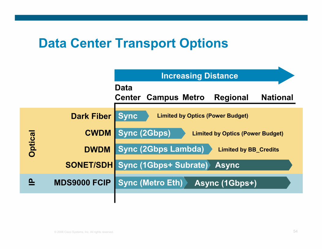
Limited by Optics (Power Budget)
Data Center Transport Options
Dark Fiber
CWDM
DWDM
SONET/SDH
Data Center Campus Metro Regional National
Increasing Distance
Async
Async (1Gbps+)MDS9000 FCIP
Limited by Optics (Power Budget)
Limited by BB_Credits
Optical
IP
Sync
Sync (2Gbps)
Sync (2Gbps Lambda)
Sync (1Gbps+ Subrate)
Sync (Metro Eth)

© 2006 Cisco Systems, Inc. All rights reserved. 55
DATA CENTERARCHITECTURE TRENDS
555555© 2005 Cisco Systems, Inc. All rights reserved.

© 2006 Cisco Systems, Inc. All rights reserved. 56
Cisco Data Center Vision
Centralization and standardization to lower costs, improve efficiency
and uptime
Centralization and standardization to lower costs, improve efficiency
and uptime
CONSOLIDATIONCONSOLIDATION
VIRTUALIZATIONVIRTUALIZATIONLANWANMAN
LANWANMAN
SANSAN
Storage NetworkStorage Network
Data NetworkData
NetworkAUTOMATIONAUTOMATION
StorageNetworkCompute
EnterpriseApplicationsEnterpriseApplications
StorageStorage
NetworkNetwork
ComputeCompute
Business PoliciesOn-Demand
Service Oriented
Business PoliciesOn-Demand
Service OrientedManagement of resources independent of underlying physical infrastructure to
increase utilization, efficiency and flexibility
Management of resources independent of underlying physical infrastructure to
increase utilization, efficiency and flexibility
Dynamic provisioning and autonomic Information
Lifecyle Management (ILM) to enable business agility
Dynamic provisioning and autonomic Information
Lifecyle Management (ILM) to enable business agility
Intelligent Information Network
Intelligent Information Network
Server FabricNetwork
Server FabricNetwork
HPCClusterGRID
HPCClusterGRID

© 2006 Cisco Systems, Inc. All rights reserved. 57
Summary

© 2006 Cisco Systems, Inc. All rights reserved. 58
What we have talk so far?
� DR and its Business Objectives
Define budget, Technical solution
Management Buy In
DR is a process
� Components of a Data Center
Multi Tier Architecture
Front-end, Application, Backend Database
� Techniques in Data Center Disaster Recovery
HTML Re-Direction/GSS/RHI
Clustering
SAN extension
� Trends in Data Center Technology
© 2006 Cisco Systems, Inc. All rights reserved. 59
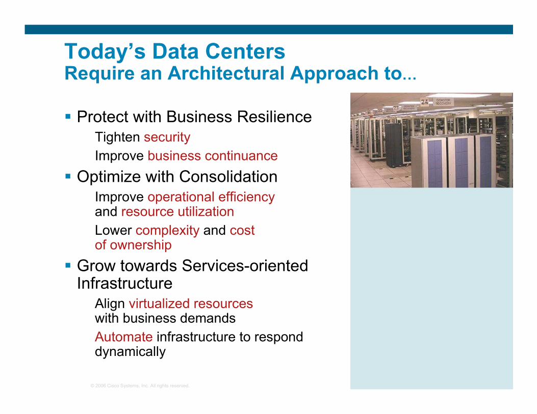
Today’s Data Centers Require an Architectural Approach to…
� Protect with Business ResilienceTighten security
Improve business continuance
� Optimize with ConsolidationImprove operational efficiencyand resource utilization
Lower complexity and cost of ownership
� Grow towards Services-oriented Infrastructure
Align virtualized resourceswith business demands
Automate infrastructure to respond dynamically

© 2006 Cisco Systems, Inc. All rights reserved. 60
The Big Picture—The Cisco Data Center
The EmergingData CenterArchitecture
MultiprotocolGateway Services
ENTERPRISE TAPE STORAGE
ENTERPRISEDISK STORAGE
MAINFRAMECONNECTIVITY
TOPSPINFAMILY
Catalyst 6500Family
Enterprise NAS Storage
BladeServers
UNIX/WindowsServers
SERVER FABRIC
SWITCHING
SSL Termination
VPN Termination
Firewall Services
Intrusion Detection
Server Balancing
Server Farm Switching
MDS 9000Family
Virtual Private ServerFabric #1
Virtual PrivateBlade ServerFabric #3
Virtual PrivateServerFabric #2
ENTERPRISE SAN SWITCHING
Embedded Intelligent Network Services
Embedded Intelligent Virtualization Services
Server VirtualizationVFrame
V
Low Latency RDMA Services
Virtual I/O
Clustering
Fabric Routing Svcs
Data Replication Svcs
Storage Virtualization
Virtual Fabrics (VSANs)Embedded Intelligent Storage Services
ENTERPRISE GRID
Grid/Utility Computing
NAS UNIXWIN

© 2006 Cisco Systems, Inc. All rights reserved. 61
What’s Next?
� A Security Strategy to Protect the Data Center
Understands the vulnerabilities, and apply the relevant mitigations
� Leverage on Cisco’s Technology to
Optimize the Server Resources
Reducing TCO for DRs
Virtualization to maximize resource invested
Grow DC infrastructure, enabling Business Agility
Automating computing resources provisioning
Speed of deploying new services

© 2006 Cisco Systems, Inc. All rights reserved. 62
Q and A

© 2006 Cisco Systems, Inc. All rights reserved. 63