Data brief - ST33TPHF2XSPI - Long-term evolution Flash ...TPM firmware and critical data upon...
21
For further information contact your local STMicroelectronics sales office. November 2019 DB3421 Rev 3 1/21 ST33TPHF2XSPI Long-term evolution Flash-memory-based TPM 2.0 device with an SPI interface Data brief Features TPM features • Flash-memory-based trusted platform module (TPM) • Compliant with Trusted Computing Group (TCG) Trusted Platform Module (TPM) Library specifications 2.0, Level 0, Revision 138 and TCG PC Client Specific TPM Platform Specifications 1.03 • Fault-tolerant firmware loader that keeps the TPM fully functional when the loading process is interrupted (self-recovery) • SP800-193 compliant for protection, detection and recovery requirements • Targeted certifications: – CC according to TPM 2.0 PP at EAL4+ – FIPS 140-2 level 2 (physical security level 3) – TCG certification • SPI support at up to 33 MHz Hardware features • Arm ® SecurCore ® SC300™ 32-bit RISC core • Highly reliable Flash memory technology • Extended temperature range: −40 °C to 105 °C • ESD protection up to 4 kV (HBM) • 1.8 V or 3.3 V supply voltage range Security features • Active shield and environmental sensors • Monitoring of environmental parameters (power) • Hardware and software protection against fault injection • FIPS compliant RNG built on an SP800-90A compliant SHA256 DRBG and an AIS-31 Class PTG2 compliant true random number generator (TRNG) • Cryptographic algorithms: – RSA key generation (1024 or 2048 bits) – RSA signature (RSASSA-PSS,RSASSA- PKCS1v1_5) – RSA encryption (RSAES-OAEP, RSAES- PKCS1-v1_5) – SHA-1, SHA-2 (256 and 384 bits), SHA-3 (256 and 384 bits) – HMAC SHA-1, SHA-2 and SHA-3 – AES-128,192 and 256 bits – TDES 192 bits – ECC (NIST P-256, P-384 curves): Key generation, ECDH and ECDSA, ECSchnorr – ECDAA (BN-256 curve) • Device provided with 3 EK and EK certificates (RSA2048, ECC NIST P_256 and ECC NIST P_384) • Device provisioned with 3 RSA key pairs to reduce the TPM provisioning time Product compliance • TPM 2.0 compliant with Microsoft ® Windows ® 8.1 and 10 • Compliant with Intel ® TXT for TPM 2.0 • Compliant with TCG test suite for TPM 2.0 TSSOP28 VFQFPN32 STSAFE-TPM (9.7 × 4.4 mm) (5 × 5 mm) www.st.com
Transcript of Data brief - ST33TPHF2XSPI - Long-term evolution Flash ...TPM firmware and critical data upon...

For further information contact your local STMicroelectronics sales office.
November 2019 DB3421 Rev 3 1/21
ST33TPHF2XSPI
Long-term evolution Flash-memory-based TPM 2.0 device with an SPI interface
Data brief
Features
TPM features• Flash-memory-based trusted platform module
(TPM)• Compliant with Trusted Computing Group
(TCG) Trusted Platform Module (TPM) Library specifications 2.0, Level 0, Revision 138 and TCG PC Client Specific TPM Platform Specifications 1.03
• Fault-tolerant firmware loader that keeps the TPM fully functional when the loading process is interrupted (self-recovery)
• SP800-193 compliant for protection, detection and recovery requirements
• Targeted certifications:– CC according to TPM 2.0 PP at EAL4+– FIPS 140-2 level 2
(physical security level 3)– TCG certification
• SPI support at up to 33 MHz
Hardware features• Arm® SecurCore® SC300™ 32-bit RISC core• Highly reliable Flash memory technology• Extended temperature range: −40 °C to 105 °C• ESD protection up to 4 kV (HBM)• 1.8 V or 3.3 V supply voltage range
Security features• Active shield and environmental sensors• Monitoring of environmental parameters
(power)• Hardware and software protection against fault
injection• FIPS compliant RNG built on an SP800-90A
compliant SHA256 DRBG and an AIS-31 Class PTG2 compliant true random number generator (TRNG)
• Cryptographic algorithms:– RSA key generation (1024 or 2048 bits)– RSA signature (RSASSA-PSS,RSASSA-
PKCS1v1_5)– RSA encryption (RSAES-OAEP, RSAES-
PKCS1-v1_5)– SHA-1, SHA-2 (256 and 384 bits), SHA-3
(256 and 384 bits)– HMAC SHA-1, SHA-2 and SHA-3– AES-128,192 and 256 bits– TDES 192 bits– ECC (NIST P-256, P-384 curves): Key
generation, ECDH and ECDSA, ECSchnorr– ECDAA (BN-256 curve)
• Device provided with 3 EK and EK certificates (RSA2048, ECC NIST P_256 and ECC NIST P_384)
• Device provisioned with 3 RSA key pairs to reduce the TPM provisioning time
Product compliance• TPM 2.0 compliant with Microsoft® Windows®
8.1 and 10• Compliant with Intel® TXT for TPM 2.0• Compliant with TCG test suite for TPM 2.0
TSSOP28 VFQFPN32
STSAFE-TPM
(9.7 × 4.4 mm) (5 × 5 mm)
www.st.com

Contents ST33TPHF2XSPI
2/21 DB3421 Rev 3
Contents
1 Description . . . . . . . . . . . . . . . . . . . . . . . . . . . . . . . . . . . . . . . . . . . . . . . . . 5
2 Pin and signal descriptions . . . . . . . . . . . . . . . . . . . . . . . . . . . . . . . . . . . 6
3 Package information . . . . . . . . . . . . . . . . . . . . . . . . . . . . . . . . . . . . . . . . . 83.1 TSSOP28 package information . . . . . . . . . . . . . . . . . . . . . . . . . . . . . . . . . 8
3.2 VFQFPN32 package information . . . . . . . . . . . . . . . . . . . . . . . . . . . . . . . 10
3.3 Thermal characteristics of packages . . . . . . . . . . . . . . . . . . . . . . . . . . . . 12
4 Delivery packing . . . . . . . . . . . . . . . . . . . . . . . . . . . . . . . . . . . . . . . . . . . 13
5 Package marking information . . . . . . . . . . . . . . . . . . . . . . . . . . . . . . . . 16
6 Ordering information . . . . . . . . . . . . . . . . . . . . . . . . . . . . . . . . . . . . . . . 17
7 Support and information . . . . . . . . . . . . . . . . . . . . . . . . . . . . . . . . . . . . 18
Revision history . . . . . . . . . . . . . . . . . . . . . . . . . . . . . . . . . . . . . . . . . . . . . . . . . . . . 20

DB3421 Rev 3 3/21
ST33TPHF2XSPI List of tables
3
List of tables
Table 1. Pin descriptions . . . . . . . . . . . . . . . . . . . . . . . . . . . . . . . . . . . . . . . . . . . . . . . . . . . . . . . . . . 7Table 2. TSSOP28 - mechanical data . . . . . . . . . . . . . . . . . . . . . . . . . . . . . . . . . . . . . . . . . . . . . . . . 8Table 3. VFQFPN32 - mechanical data . . . . . . . . . . . . . . . . . . . . . . . . . . . . . . . . . . . . . . . . . . . . . . 10Table 4. Thermal characteristics. . . . . . . . . . . . . . . . . . . . . . . . . . . . . . . . . . . . . . . . . . . . . . . . . . . . 12Table 5. Packages on tape and reel . . . . . . . . . . . . . . . . . . . . . . . . . . . . . . . . . . . . . . . . . . . . . . . . . 13Table 6. Reel dimensions . . . . . . . . . . . . . . . . . . . . . . . . . . . . . . . . . . . . . . . . . . . . . . . . . . . . . . . . . 14Table 7. Carrier tape dimensions for VFQFPN 5 × 5 mm. . . . . . . . . . . . . . . . . . . . . . . . . . . . . . . . . 14Table 8. Carrier tape constant dimensions for TSSOP 4.4 mm body width . . . . . . . . . . . . . . . . . . . 15Table 9. Ordering information for the ST33TPHF2X product family . . . . . . . . . . . . . . . . . . . . . . . . . 17Table 10. List of abbreviations . . . . . . . . . . . . . . . . . . . . . . . . . . . . . . . . . . . . . . . . . . . . . . . . . . . . . . 19Table 11. Document revision history . . . . . . . . . . . . . . . . . . . . . . . . . . . . . . . . . . . . . . . . . . . . . . . . . 20

List of figures ST33TPHF2XSPI
4/21 DB3421 Rev 3
List of figures
Figure 1. TSSOP28 pinout . . . . . . . . . . . . . . . . . . . . . . . . . . . . . . . . . . . . . . . . . . . . . . . . . . . . . . . . . 6Figure 2. VQFN32 pinout . . . . . . . . . . . . . . . . . . . . . . . . . . . . . . . . . . . . . . . . . . . . . . . . . . . . . . . . . . 6Figure 3. TSSOP28 - outline . . . . . . . . . . . . . . . . . . . . . . . . . . . . . . . . . . . . . . . . . . . . . . . . . . . . . . . . 8Figure 4. TSSOP28 - recommended footprint . . . . . . . . . . . . . . . . . . . . . . . . . . . . . . . . . . . . . . . . . . . 9Figure 5. VFQFPN32 - outline . . . . . . . . . . . . . . . . . . . . . . . . . . . . . . . . . . . . . . . . . . . . . . . . . . . . . 10Figure 6. VFQFPN32 - recommended footprint . . . . . . . . . . . . . . . . . . . . . . . . . . . . . . . . . . . . . . . . . 11Figure 7. Reel diagram . . . . . . . . . . . . . . . . . . . . . . . . . . . . . . . . . . . . . . . . . . . . . . . . . . . . . . . . . . . 13Figure 8. Embossed carrier tape for VFQFPN 5 × 5 mm. . . . . . . . . . . . . . . . . . . . . . . . . . . . . . . . . . 14Figure 9. Chip orientation in the embossed carrier tape for VFQFPN 5 × 5 mm . . . . . . . . . . . . . . . . 14Figure 10. Embossed carrier tape for TSSOP28 4.4 mm body width . . . . . . . . . . . . . . . . . . . . . . . . . 15Figure 11. Chip orientation in the embossed carrier tape for TSSOP28 4.4 mm body width. . . . . . . . 15Figure 12. TSSOP28 device package marking area . . . . . . . . . . . . . . . . . . . . . . . . . . . . . . . . . . . . . . 16Figure 13. VQFN32 device package marking area . . . . . . . . . . . . . . . . . . . . . . . . . . . . . . . . . . . . . . . 16

DB3421 Rev 3 5/21
ST33TPHF2XSPI Description
7
1 Description
The STSAFE-TPM (trusted platform module) family of products offers a broad portfolio of standardized solutions for embedded, PC, mobile and computing applications. STSAFE is an ST trademark.
It includes turnkey products compliant with the Trusted Computing Group (TCG) standards that provide services to protect the confidentiality, integrity and authenticity of information and devices.
These devices are easy to integrate thanks to the variety of supported interfaces and the availability of TPM ecosystem software solutions.
The STSAFE-TPM devices are all Common Criteria (EAL4+) and FIPS certified.
They embed an Arm®(a) SecurCore® SC300™ processor with additional security features to help protect against advanced forms of attack.
The ST33TPHF2XSPI offers a slave serial peripheral interface (SPI) compliant with the TCG PC Client TPM Profile specifications.
It offers resilience services during the TPM firmware upgrade process, and self-recovery of TPM firmware and critical data upon failure detection.
The ST33TPHF2XSPI operates in the –25 to +85 °C commercial temperature range at 1.8 V, or in the –40 °C to 105 °C extended temperature range at 3.3 V.
The device is offered in TSSOP28 and VFQFPN32 ECOPACK2 packages. ECOPACK is an ST trademark.
a. Arm is a registered trademark of Arm Limited (or its subsidiaries) in the US and/or elsewhere.

Pin and signal descriptions ST33TPHF2XSPI
6/21 DB3421 Rev 3
2 Pin and signal descriptions
Figure 1 and Figure 2 give the pinouts of the two packages in which the devices are delivered. Table 1 describes the associated signals.
Figure 1. TSSOP28 pinout
Figure 2. VQFN32 pinout
MSv52769V1.
TSSOP287GPIO_PP8
GND
9NiC10NiC11NiC121314NiC
MISO
NiC
VPSMOSI
SPI_CLK
123456
NiCNiC
NiC
GPIO_LPNiC
NiCNiCNiC
2221201918171615
282726252423
NiCNiCNiC
NiCNiC
NiC
SPI_CS
SPI_PIRQ
SPI_RST
MSv52770V1.
VQFN32
1NiC2GND3NiC4NiC5NiC6GPIO_LP7GPIO_PP8NiC
32
NiC
31
NiC
30
NiC
29
NiC
28
NiC
27
NiC
26
NiC
25
NiC
MISONiCVPSMOSISPI_CSSPI_CLKSPI_PIRQSPI_RST
24
23
22
21
20
19
18
17
9 10 11 12 13 14 15 16
NiC
NiC
NiC
NiC
NiC
NiC
NiC
NiC
33NiC

DB3421 Rev 3 7/21
ST33TPHF2XSPI Pin and signal descriptions
7
Note: The VQFN32 package has a central pad (PIN33) on the bottom, which is not connected to the die. This pin does not impact the TPM, be it connected or not.
Table 1. Pin descriptions
Signal Type Description
VPS Input Power supply. This pin must be connected to 1.8 V or 3.3 V DC power rail supplied by the motherboard.
GND Input GND has to be connected to the main motherboard ground.
SPI_RST Input SPI Reset, active low, used to re-initialize the device. Must not be unconnected. External pull-up required if it cannot be driven.
MISO Output SPI Master Input, Slave Output (output from slave)
MOSI Input SPI Master Output, Slave Input (output from master)
SPI_CLK Input SPI Serial Clock (output from master)
SPI_CS Input SPI Chip (or Slave) Select, internal pull-up (active low; output from master)
SPI_PIRQ Output SPI IRQ, active low, open drain, used by TPM to generate an interrupt
GPIO_PP InputPhysical Presence, active high, internal pull-down. Used to indicate Physical Presence to the TPM. The GPIO function could be modified by activating the GPIOs mapped on the NV storage index feature.
GPIO_LP InputBy default: Used for activation and deactivation of the TPM Standby mode (TPMLowPowerByGpio). The GPIO function could be modified by activating the GPIOs mapped on the NV storage index feature.
NiC - Not internally connected: not connected to the die. May be left unconnected, but has no impact on the TPM if connected.

Package information ST33TPHF2XSPI
8/21 DB3421 Rev 3
3 Package information
In order to meet environmental requirements, ST offers these devices in different grades of ECOPACK packages, depending on their level of environmental compliance. ECOPACK specifications, grade definitions and product status are available at: www.st.com. ECOPACK is an ST trademark.
3.1 TSSOP28 package informationThe TSSOP28 package is a 28-lead thin shrink small outline package with the following dimensional features: 9.7 × 4.4 mm and 0.65 mm pitch.
Unless otherwise specified, general tolerance is ± 0.1 mm.
Figure 3. TSSOP28 - outline
1. Drawing is not to scale.
Table 2. TSSOP28 - mechanical data
Symbolmillimeters inches(1)
Min. Typ. Max. Min. Typ. Max.
A - - 1.20 - - 0.047A1 0.05 - 0.15 0.002 - 0.006A2 0.80 1.00 1.05 0.031 0.040 0.041b 0.19 - 0.30 0.007 - 0.012c 0.09 - 0.20 0.004 - 0.008D 9.60 9.70 9.80 0.378 0.382 0.386E 6.20 6.40 6.60 0.244 0.252 0.260
E1 4.30 4.40 4.50 0.170 0.173 0.177e - 0.65 - - 0.026 -
YM_ME
c
L
k
A1
aaa
A2A
eb
1
28
14
15
D
EE1
L1

DB3421 Rev 3 9/21
ST33TPHF2XSPI Package information
20
Figure 4. TSSOP28 - recommended footprint
1. All dimensions are in millimeters.
L 0.45 0.60 0.75 0.018 0.024 0.0230L1 - 1.00 - - 0.040 -k 0° - 8° 0° - 8°
aaa - - 0.10 - - 0.004
1. Values in inches are converted from mm and rounded to 4 decimal digits.
Table 2. TSSOP28 - mechanical data (continued)
Symbolmillimeters inches(1)
Min. Typ. Max. Min. Typ. Max.
YM_FP_V1
4.46.4
0.3
0.65
1.0
8.75
1 14
28 15
Package information ST33TPHF2XSPI
10/21 DB3421 Rev 3
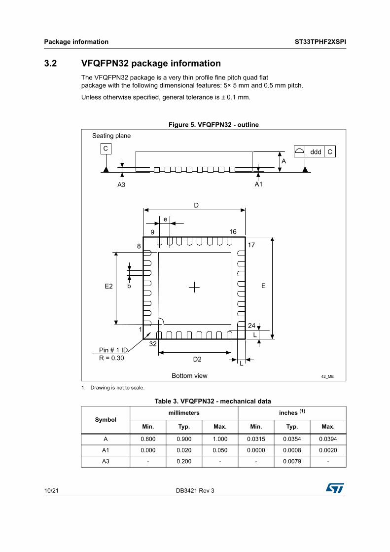
3.2 VFQFPN32 package informationThe VFQFPN32 package is a very thin profile fine pitch quad flat package with the following dimensional features: 5× 5 mm and 0.5 mm pitch.
Unless otherwise specified, general tolerance is ± 0.1 mm.
Figure 5. VFQFPN32 - outline
1. Drawing is not to scale.
Table 3. VFQFPN32 - mechanical data
Symbolmillimeters inches (1)
Min. Typ. Max. Min. Typ. Max.
A 0.800 0.900 1.000 0.0315 0.0354 0.0394
A1 0.000 0.020 0.050 0.0000 0.0008 0.0020
A3 - 0.200 - - 0.0079 -
Seating plane
ddd CC
A3 A1
A
D
e
9 16
17
24
32Pin # 1 IDR = 0.30
8
E
L
L
D2
1
bE2
42_MEBottom view

DB3421 Rev 3 11/21
ST33TPHF2XSPI Package information
20
Figure 6. VFQFPN32 - recommended footprint
b 0.180 0.250 0.300 0.0071 0.0098 0.0118
D 4.850 5.000 5.150 0.1909 0.1969 0.2028
D2 3.500 3.600 3.700 0.1378 0.1417 0.1457
E 4.850 5.000 5.150 0.1909 0.1969 0.2028
E2 3.500 3.600 3.700 0.1378 0.1417 0.1457
e - 0.500 - - 0.0197 -
L 0.300 0.400 0.500 0.0118 0.0157 0.0197
ddd - - 0.050 - - 0.0020
1. Values in inches are converted from mm and rounded to 4 decimal digits.
Table 3. VFQFPN32 - mechanical data (continued)
Symbolmillimeters inches (1)
Min. Typ. Max. Min. Typ. Max.
Ai15210All dimensions are in millimeters.
1
25
24
17
16
8
9
32
5.30
3.80
5.30
3.80
0.60
0.75
3.45
3.45
0.50
0.30

Package information ST33TPHF2XSPI
12/21 DB3421 Rev 3
3.3 Thermal characteristics of packagesThe table below provides the thermal characteristics of the TSSOP28 and VFQFPN32 packages.
Table 4. Thermal characteristics Parameter Symbol Value
Recommended operating temperature range
Ambient temperature TA −40 to 105 °C
Case temperature TC -
Junction temperature TJ −43 to 108 °C
Absolute maximum junction temperature - 125 °C
Maximum power dissipation - 63 mW
Theta-JA, Theta-JC and Theta-JB
Junction to ambient thermal resistance θJA 35.8 @ 0 lfpm(1)
1. Linear feet per minute.
Junction to case thermal resistance θJC 1.48 @ 0 lfpm(1)
Junction to board thermal resistance θJB 13.9 @ 0 lfpm(1)

DB3421 Rev 3 13/21
ST33TPHF2XSPI Delivery packing
20
4 Delivery packing
Surface-mount packages can be supplied with tape and reel packing. The reels have a 13" typical diameter.
Reels are in plastic, either anti-static or conductive, with a black conductive cavity tape. The cover tape is transparent anti-static or conductive.
The devices are positioned in the cavities with the identifying pin (normally Pin “1”) on the same side as the sprocket holes in the tape.
The STMicroelectronics Tape & Reel specifications are compliant to the EIA 481-A standard specification.
Figure 7. Reel diagram
Table 5. Packages on tape and reelPackage Description Tape width Tape pitch Reel diameter Quantity per reel
TSSOP 28 Thin shrink small outline package 16 mm 8 mm 13 in. 2500
VFQFPN 32Very thin fine pitch quad flat pack no-lead package
12 mm 8 mm 13 in. 3000
AI00650D
A
D
B
C
N
T
G

Delivery packing ST33TPHF2XSPI
14/21 DB3421 Rev 3
Figure 8. Embossed carrier tape for VFQFPN 5 × 5 mm
1. Drawing is not to scale.
Figure 9. Chip orientation in the embossed carrier tape for VFQFPN 5 × 5 mm
Table 6. Reel dimensions
Reel size Tape width A Max. B Min. C D Min. G Max. N Min. T Max. Unit
13”16
330 1.5 13 ±0.2 20.216.4 +2/–0
10022.4
mm12 12.6 18.4
AI18807V1
T
B0
K0
D
D1
Y
P2P0
Y
P A0
E
WF
Section Y - YUser direction of feed
MS41227V1User direction of feed
Table 7. Carrier tape dimensions for VFQFPN 5 × 5 mm
Package A0 B0 K0 D1 Min. P P2 D P0 E F W T
Max. Unit
FPN 5x55.25±0.1
5.25±0.1
1.1±0.1
1.58
±0.12
±0.11.55±0.05
4±0.1
1.75±0.1
5.5±0.1
12±0.3
0.3±0.05
mm

DB3421 Rev 3 15/21
ST33TPHF2XSPI Delivery packing
20
Figure 10. Embossed carrier tape for TSSOP28 4.4 mm body width
1. Drawing is not to scale.
Figure 11. Chip orientation in the embossed carrier tape for TSSOP28 4.4 mm body width
AI00652V1
W
TK
Bo
DP2
Po
B1
Ao
Bo
P
F
E
D1
User direction of feed
Ko
TopCoverTape
Typical
User direction of feedMS41228V1
Table 8. Carrier tape constant dimensions for TSSOP 4.4 mm body widthTape size Ao, Bo, Ko(1) D E Po T Max. Unit
16 mm See note. 1.5 +0.1 / -0 1.75 ±0.1 4 ±0.1 0.4 mm
1. Ao, Bo, Ko, are determined by components sizes. The clearance between the component and the cavity must be within 0.05 mm (Min.) to 0.90 mm (Max.)

Package marking information ST33TPHF2XSPI
16/21 DB3421 Rev 3
5 Package marking information
Figure 12 and Figure 13 illustrate the typical markings of the TSSOP28 and the VQFN32 device packages, respectively.
Figure 12. TSSOP28 device package marking area
Figure 13. VQFN32 device package marking area
For the two packages, the 6-digit ‘A’ marking area is equal to “PXYZZZ”, with:• Y = Hardware revision• ZZZ = Product identifier
MS47082V1
A
B C D FE
HIGa
A: Marking area – 6 digitsB: Assembly plantC: BE sequenceD: Diffusion plantE: Assembly yearF: Assembly weekG: ECOPACK levelH: ST logoI: Marking area - 2 digits - unuseda: Dot
MS47083V1
A
B C D
E F G
IJH
K
A: Marking area – 6 digits
B: Assembly plant
C: BE sequence
D: Diffusion plant
E: Country of origin
F: Assembly year
G: Assembly week
H: ECOPACK
I: ST logo
J: Marking area - 2 digits - unused
K: Dot

ST33TPHF2XSPI
Ordering inform
ation
DB3421 R
ev 317/21
6 Ordering information
Table 9. Ordering information for the ST33TPHF2X product family
Ordering code Firmware version Operating temperature range(1)
Maximum SPI clock frequency Package Marking
(area A) Product status
ST33HTPH2X28AHC40x00.01.01.00 (1.256) -40 °C to +105 °C 33 MHz
TSSOP28PXAHC4
NRND (Not recommended
for new design)ST33HTPH2X32AHC4 VQFN32
ST33HTPH2X28AHD40x00.01.01.01 (1.257) -40 °C to +105 °C 33 MHz
TSSOP28PXAHD4 Active
ST33HTPH2X32AHD4 VQFN32
1. Refer to Section 1: Description for the operating voltages associated with the different operating temperature ranges.

Support and information ST33TPHF2XSPI
18/21 DB3421 Rev 3
7 Support and information
Additional information regarding ST TPM devices can be obtained from the website www.st.com.
For any specific support information you can contact STMicroelectronics through the following e-mail: [email protected].

DB3421 Rev 3 19/21
ST33TPHF2XSPI Terms and abbreviations
20
Appendix A Terms and abbreviations
Table 10. List of abbreviations Term Meaning
AES Advanced Encryption Standard
CA Certificate authority
CC Common Criteria
DAM Dictionary attack mitigation mechanism
Data byte Byte from the TPM command or answer or register value.
DES Data Encryption Standard
EC Elliptic Curve
EK Endorsement Key
FIPS Federal Information Processing Standard
GPIO General Purpose I/O
HMAC Keyed-Hashing for Message Authentication
HSM Hardware security module
NIST National Institute of Standards and Technology
NV Non-volatile (memory)
OEM Original Equipment Manufacturer
OIAP Object-Independent Authorization Protocol
OSAP Object Specific Authorization Protocol
PCR Platform Configuration Register
RSA Rivest Shamir Adelman
RTM Root of Trust for Measurement
RTR Root of Trust for Reporting
SHA Secure Hash Algorithm
SPI Serial Peripheral Interface
SRK Storage Root Key
TCG Trusted Computed Group
TIS TPM interface specification
TPM Trusted Platform Module
TPME TPM Manufacturer
Transaction bytes All bytes from a TPM command or TPM answer.
TSS TPM Software Stack
Revision history ST33TPHF2XSPI
20/21 DB3421 Rev 3
Revision history
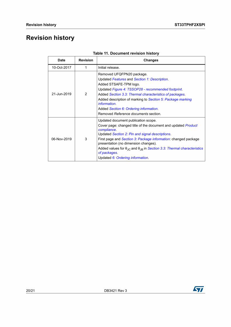
Table 11. Document revision history Date Revision Changes
10-Oct-2017 1 Initial release.
21-Jun-2019 2
Removed UFQFPN20 package.Updated Features and Section 1: Description.Added STSAFE-TPM logo.Updated Figure 4: TSSOP28 - recommended footprint.Added Section 3.3: Thermal characteristics of packages.Added description of marking to Section 5: Package marking information.Added Section 6: Ordering information.Removed Reference documents section.
06-Nov-2019 3
Updated document publication scope.Cover page: changed title of the document and updated Product compliance. Updated Section 2: Pin and signal descriptions.First page and Section 3: Package information: changed package presentation (no dimension changes).Added values for θJC and θJB in Section 3.3: Thermal characteristics of packages.Updated 6: Ordering information.

DB3421 Rev 3 21/21
ST33TPHF2XSPI
21
IMPORTANT NOTICE – PLEASE READ CAREFULLY
STMicroelectronics NV and its subsidiaries (“ST”) reserve the right to make changes, corrections, enhancements, modifications, and improvements to ST products and/or to this document at any time without notice. Purchasers should obtain the latest relevant information on ST products before placing orders. ST products are sold pursuant to ST’s terms and conditions of sale in place at the time of order acknowledgement.
Purchasers are solely responsible for the choice, selection, and use of ST products and ST assumes no liability for application assistance or the design of Purchasers’ products.
No license, express or implied, to any intellectual property right is granted by ST herein.
Resale of ST products with provisions different from the information set forth herein shall void any warranty granted by ST for such product.
ST and the ST logo are trademarks of ST. For additional information about ST trademarks, please refer to www.st.com/trademarks. All other product or service names are the property of their respective owners.
Information in this document supersedes and replaces information previously supplied in any prior versions of this document.
© 2019 STMicroelectronics – All rights reserved