DATA ACQUISTION AND SIGNAL PROCESSING Dr. Tayab Din Memon Lecture Introduction to Opamps & Multisim.
34
DATA ACQUISTION AND SIGNAL PROCESSING Dr. Tayab Din Memon Lecture Introduction to Opamps & Multisim
-
Upload
laurence-green -
Category
Documents
-
view
223 -
download
1
Transcript of DATA ACQUISTION AND SIGNAL PROCESSING Dr. Tayab Din Memon Lecture Introduction to Opamps & Multisim.

DATA ACQUISTION AND SIGNAL PROCESSING
Dr. Tayab Din Memon
Lecture
Introduction to Opamps & Multisim

Objectives To introduce the amplifier and its Transfer
Characteristics. Opamp
Definition, Internal Architecture, Notation, and its Package.
Ideal Characteristics of Opamp. Differential Mode of Opamp. Power of Negative Feedback Opamp Modes of Operation
Inverting Non-Inverting Differential
Session-II Lab Work Simulation of Modes of Opamp.

Amplifier?
Why do we need to amplify signals? Why do we need to amplify signals?
To increase level of signals.
To increase level of signals.
SENSORANALOG TO
DIGITALCONVERSION
SIGNALCONDITIONING
PHYSICALPHENOMENA
DIGITALOUTPUT

Amplifier-Transfer Characteristics
Transfer Characteristic is the relationship between input and output voltages
Transfer Characteristic is the relationship between input and output voltages
The level of signal amplification is called the Gain, Av, and is the slope of the amplifier transfer characteristics.
The level of signal amplification is called the Gain, Av, and is the slope of the amplifier transfer characteristics.
Input voltage is Vi
Output voltage is Vo
Input voltage is Vi
Output voltage is Vo

How do we build an amplifier?
Discrete Devices, Transistors, Resistors, Capacitors.
Discrete Devices, Transistors, Resistors, Capacitors.
Attractive Solution
Attractive Solution
Use of the Integrated Circuits – Operational Amplifiers (Op-Amp)
Use of the Integrated Circuits – Operational Amplifiers (Op-Amp)
Inexpensive, Easy to use, and readily available.
Inexpensive, Easy to use, and readily available.

How Opamp can be Defined?
The op-amp is a high gain dc amplifier that has high input impedance and low output impedance.
The op-amp is a high gain dc amplifier that has high input impedance and low output impedance.
Note: Op-amps are analog, rather than digital devices, although they are used in many digital instrument.
Note: Op-amps are analog, rather than digital devices, although they are used in many digital instrument.
DC Amplifier – An amplifier that is capable of amplifying dc voltages and slowly varying voltages.

Op-Amp Definition
An operational amplifier (op-amp) is a DC-coupled (?)high-gain electronic voltage amplifier with a differential input and, usually, a single-ended output. An op-amp produces an output voltage that is typically hundreds of thousands of times larger than the voltage difference between its input terminals [source: Wikipedia].

DC Coupled Direct coupled refers to coupling between stages of an
amplifier and coupling of the output stage to the load. The reason for coupling devices between stages is to accommodate the different DC biases needed by each stage. Normally you can't just connect the collector output of one stage to the base input of another identical stage, since collector and base operate at very different voltages. So an interstage transformer or capacitor provides DC isolation between stages while passing the audio.
Direct-coupled interstage designs often use complementary stages; a PNP transistor drives an NPN transistor, etc. This makes it much easier to obtain bias compatibility between stages. See ref, figure 2.5.Direct output coupling is used to eliminate the nonlinearity, phase-shift and limited frequency response of a transformer or capacitor. The drawback is the possibility of applying a DC bias to the load. Direct output coupled amplifiers usually have a bias nulling adjustment which may need occasional adjustment.

Internal Structure of Opamp.

Op-amp Notation
-
+v+
v-
VO
v+
v- -
+
+Vcc
v0
-Vcc
The Opamp has minimum five terminals:
Two Signal Input Terminals: +v and –v
One Output terminal vo
Two dc Power Supply Terminals +Vcc and –Vcc
The Opamp has minimum five terminals:
Two Signal Input Terminals: +v and –v
One Output terminal vo
Two dc Power Supply Terminals +Vcc and –Vcc

Opamp Packages
Opamp uA741 present in 8pin Dip IC. Also available in different size pins i.e. 16 also.
Opamp uA741 present in 8pin Dip IC. Also available in different size pins i.e. 16 also.
Pin ConfigurationIC Package

Opamp Transfer Characteristics…..
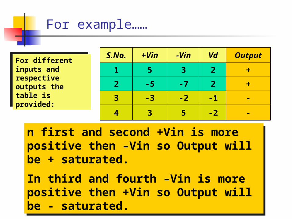
For example……
S.No. +Vin -Vin Vd Output
1 5 3 2 +
2 -5 -7 2 +
3 -3 -2 -1 -
4 3 5 -2 -
n first and second +Vin is more positive then –Vin so Output will be + saturated.
In third and fourth –Vin is more positive then +Vin so Output will be - saturated.
n first and second +Vin is more positive then –Vin so Output will be + saturated.
In third and fourth –Vin is more positive then +Vin so Output will be - saturated.
For different inputs and respective outputs the table is provided:
For different inputs and respective outputs the table is provided:

Opamp Saturation ………..
Input Signal
30v pk-pk.
Output Signal 30V pk-pk Gain 1,000,000 Op-Amp Saturates at 10V
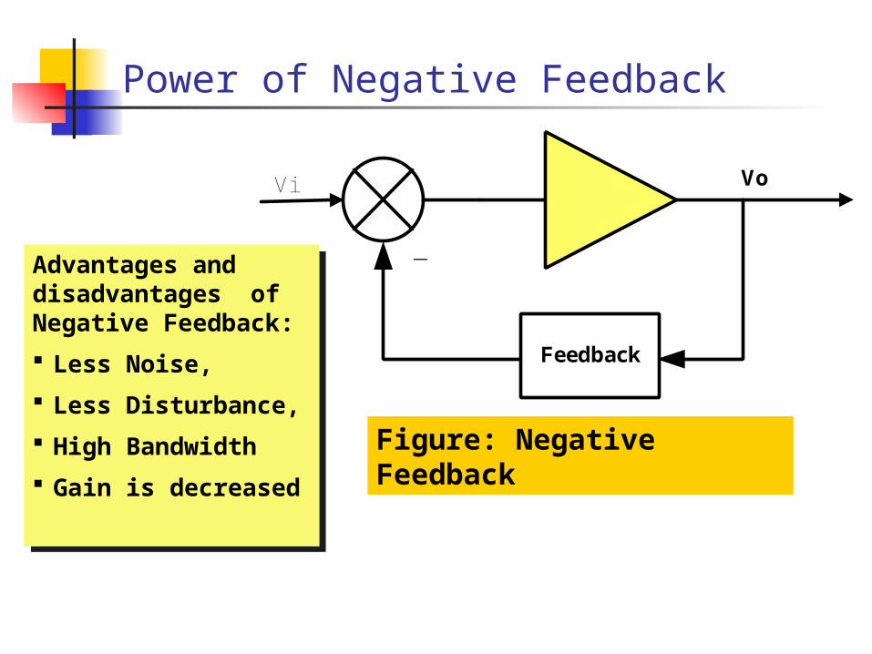
Power of Negative Feedback
Figure: Negative Feedback
Vi
Feedback
Vo
-Advantages and disadvantages of Negative Feedback:
Less Noise,
Less Disturbance,
High Bandwidth
Gain is decreased
Advantages and disadvantages of Negative Feedback:
Less Noise,
Less Disturbance,
High Bandwidth
Gain is decreased

Opamp Modes of Operation
Inverting Mode Noninverting Mode Differential Mode
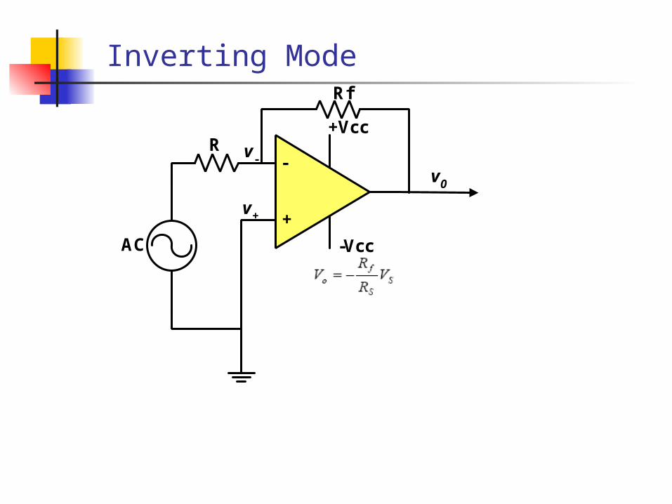
Inverting ModeRf
AC
v+
v- -
+
+Vcc
v0
-Vcc
R

Non-Inverting Mode Rf
AC
v+
v- -
+
+Vcc
v0
-Vcc
R

AC
v+
v- -
+
+Vcc
v0
-Vcc
AC
Differential Mode
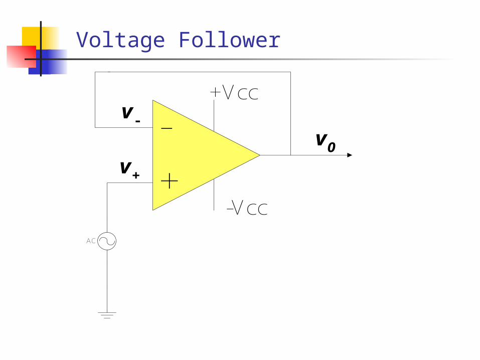
Voltage Follower
v+
v- -
+
+Vcc
v0
-Vcc
AC


SESSION II
LAB WORK
All tasks given in the Handout should be
completed

Introduction to MultiSim
Multisim is fully featured SPICE schematiccapture and simulation tool used for circuit design, simulation, and in combination with Ultiboard for layout of custom PCBs.

Design of an amplifier with a gain 10.
TASK-I
Design an amplifier with gain of 10?
Mode choice is open!!
Ok! Design using Inverting mode. In inverting mode Voltage gain is ratio of Feedback Resistance to Input Resistance. Vo/Vi= -(Rf/Ri).
So Select Rf=10KΩ and Ri=1KΩ, then voltage gain will be 10. HERE IS THE SOLUTION!!

Inverting Amplifier with Gain 10.
Rf=10K
AC
v+
v- -
+
+Vcc
v0
-Vcc
R=1K
1V/1KHz

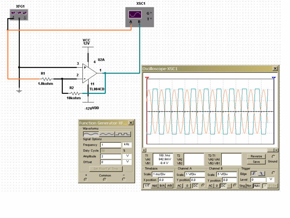
WHAT DIFFERENCE DID YOU OBSERVE IN TWO OUTPUTS?
ANSWER?
Saturation Due to input voltage increase.

Repeat same Task with Non-Inverting Amplifier.
In Non-inverting mode Voltage gain is: 1+Rf/Ri.
So if we select Rf=4.7KΩ then Ri=0.52KΩ ~0.51K Ω (because 0.51K Ω is a standard Resistor).
If we place these values then Output of the Circuit should be 10.
HERE IS SOLUTION


Voltage Follower Simulated Result
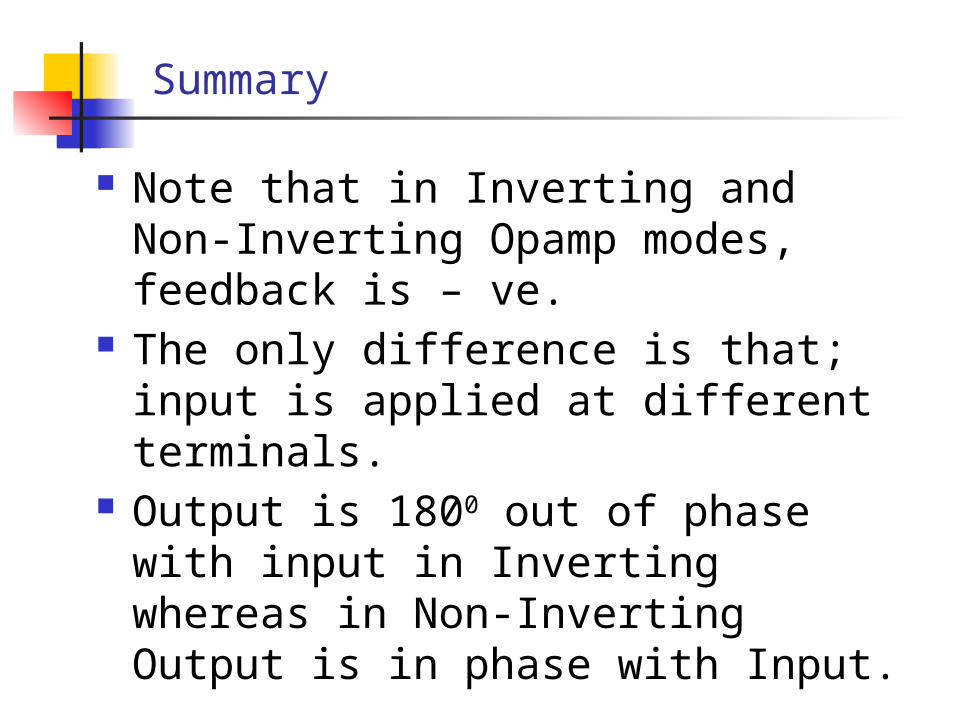
Summary
Note that in Inverting and Non-Inverting Opamp modes, feedback is – ve.
The only difference is that; input is applied at different terminals.
Output is 1800 out of phase with input in Inverting whereas in Non-Inverting Output is in phase with Input.