Data Acquisition Operator's Manual - Agilent · Star Toolbar ... Specifying the Data File Name and...
94
Varian Analytical Instruments 2700 Mitchell Drive Walnut Creek, CA 94598-1675/USA Star Chromatography Workstation Version 6 Data Acquisition Operation Manual ©Varian, Inc. 2002 03-914729-00:Rev. 4
Transcript of Data Acquisition Operator's Manual - Agilent · Star Toolbar ... Specifying the Data File Name and...
Varian Analytical Instruments 2700 Mitchell Drive Walnut Creek, CA 94598-1675/USA
Star Chromatography Workstation Version 6
Data Acquisition
Operation Manual
©Varian, Inc. 2002 03-914729-00:Rev. 4
ros
Temp Errata
Trademark Acknowledgment
Microsoft, Windows, Windows 95, Windows 98, Windows NT, and Windows 2000 are registered trademarks of Microsoft Corporation.
Other brand and product names are trademarks or registered trademarks of their respective holders.

Table of Contents
Getting Started......................................................................................... 1 About this Manual .........................................................................................................1 Additional Manuals........................................................................................................1
Data Handling and Reports Operation Manual....................................................1 Data Handling and Reports Tutorial Manual .......................................................1
Star Toolbar ..................................................................................................................2 Elements of the Star Toolbar ...............................................................................3 Application Buttons ..............................................................................................3 Quick Link Buttons ...............................................................................................4 Star Toolbar Options............................................................................................4
Starting System Control the First Time.........................................................................5 Configuring an Instrument.............................................................................................8
Modules and Instruments Defined .......................................................................8 Elements of the Configuration Screen .................................................................8 Setting Instrument Parameters ............................................................................9
The Instrument Window ................................................................................................9 Elements of the Instrument Window ..................................................................10 Displaying ADC Board Status and Control Window ..........................................10 Configuring the ADC Board Status and Control Window ..................................11 Configuring the Real-Time Chromatogram Display...........................................11 Documenting Module Information......................................................................13
Data Acquisition i

Ethernet Communication Setup ........................................................... 15 What Do I need to Know about Networks...................................................................16
Isolated Network ................................................................................................16 Company Network .............................................................................................17
Where to Begin ...........................................................................................................19 Setting the Network Properties for Isolated Network..................................................19 Setting the Network Properties for a Company Network ............................................22 Setting the Star WS BOOTP Server to Assign IP Addresses.....................................23
Assigning IP Addresses from Star WS BOOTP Server.....................................25 Adding Star 800 MIB to Instruments in System Control .............................................28
Using the Star 800 MIB.......................................................................... 31 Connecting to an Instrument.......................................................................................31
Analog Signals ...................................................................................................32 Synchronization Signals.....................................................................................33 Serial Communication Signals...........................................................................34
The Star 800 MIB Status Window...............................................................................35 Star 800 MIB Method ..................................................................................................36
Building Methods .................................................................................. 37 Overview .....................................................................................................................37 Using Star Assistant to Create a new Method ............................................................38 The Method Builder Window.......................................................................................41 Editing a Method .........................................................................................................42
Method Notes.....................................................................................................42 ADC Board Data Acquisition Settings................................................................43 Post-run Processing...........................................................................................45
The Startup Method ....................................................................................................50 Editing Methods from the ADC Board Status and Control Window............................50 Changing Method Endtime from the ADC Board Status and Control Window...........50 Importing Method Sections .........................................................................................51 Deleting Method Sections ...........................................................................................52 Printing the Method .....................................................................................................52 Password Protecting a Method ...................................................................................52
Injecting a Single Sample ..................................................................... 53 Using the Inject Single Sample Dialog Box ................................................................53 Specifying the Data File Name and Path....................................................................54 Specifying Per-Sample Data Handling Parameters....................................................56 Specifying a RecalcList ...............................................................................................58 Monitoring the Status of the Run ................................................................................59 Using QuickStart .........................................................................................................60
ii 03-914729-00:4

TABLE OF CONTENTS
Injecting Multiple Samples.................................................................... 63 Using a SampleList in System Control........................................................................63 Specifying the Data File Name and Path....................................................................66 Specifying Per-Sample Data Handling Parameters....................................................68 Specifying a RecalcList ...............................................................................................70 Changing Default SampleList Entries .........................................................................70 Monitoring the Status of Runs.....................................................................................71 Saving SampleLists for Later Use...............................................................................72 Using More Than One Method for Injections ..............................................................72
Changing the Method in the SampleList............................................................72 Using the Sequence Window.............................................................................74
Automation File Editor .......................................................................... 77 Accessing the Automation File Editor .........................................................................77 Editing or creating a RecalcList ..................................................................................78 Editing or creating a SampleList .................................................................................80 Specifying the Data File Name and Path....................................................................82 Specifying Per-Sample Data Handling Parameters....................................................84 Specifying a RecalcList ...............................................................................................85 Changing Default SampleList Entries .........................................................................86 Using More Than One Method for Injections ..............................................................86 Editing or creating a Sequence...................................................................................88
Data Acquisition iii

iv 03-914729-00:4

Getting Started
About this Manual This manual describes the operation of the Star Chromatography Workstation when used with the Star ADC Board for chromatography data acquisition. It covers configuring an instrument for data acquisition, building a method, and running samples. For post-run data handling, peak integration, and standard report generation, please refer to the Data Handling and Reports Operation Manual.
Additional Manuals Other sources of information are available to help you get the most from this product.
Data Handling and Reports Operation Manual
This manual describes post-run and interactive data handling, standard report generation, and advanced application.
Data Handling and Reports Tutorial Manual The tutorials provide a practical way to quickly learn how to perform basic tasks using the Star Chromatography Software. These Tutorials cover Star Workstation operation that is common to all instrument configurations.
Data Acquisition 1

Star Toolbar
Star Chromatography Workstation is a suite of applications for controlling chromatographs, collecting data from chromatograph detectors, and analyzing that data. The Star Toolbar provides quick and easy access to the Star Chromatography Workstation applications. When activated the Star Toolbar behaves very much like the Windows Taskbar. It can be docked on any of the four sides of the display screen and other Windows programs will not cover or go behind it when they are opened in full screen mode.
If the Star Toolbar is not already opened on your Star Workstation, you can start it from the Windows Start Menu.
2 03-914729-00:4

GETTING STARTED Star Toolbar
Elements of the Star Toolbar
Application Buttons for immediate access to the selected application.
Application Descriptions give a brief description of the application that will be opened when the cursor rests on the Application Button.
Quick Link Buttons provide menu selections of operations to be performed on the listed file.
ToolTip shows the application name when the cursor rests on the Application Button.
Application Buttons
Used to monitor instrument status, perform automated injections, and perform batch recalculations.
Used to view and edit instrument operation, data acquisition, and data handling methods.
Used to review chromatograms, interactively edit data handling parameters, and recalculate results.
Used to preview standard chromatogram and results reports.
Used for offline editing of SampleLists, RecalcLists and Sequences.
Used to generate standard reports for a group of Data Files by dragging and dropping them on the Batch Report Window.
Used to set Star Workstation security options and passwords.
Other application buttons may be added to the Star Toolbar when you install additional Star Workstation Options, such as StarFinder, Star Custom Report Writer, and PolyView2000.
Data Acquisition 3

Quick Link Buttons
Most Recently Used Data File
Menu of operations that can be performed on the Most Recently Used Data File.
List of Most Recently Used Files
Most Recently Used Method
Menu of operations that can be performed on the Most Recently Used Method.
List of the Most Recently Used Methods
Star Toolbar Options
Menu of Star ToolBar configuration options and operations that may be performed.
4 03-914729-00:4

GETTING STARTED Starting System Control the First Time
Starting System Control the First Time The first time that you use the Star Chromatography Workstation to control your instrument, collect chromatographic data and generate results, you must configure the System Control application. The System Control Configuration Window allows you to set the communication parameters for each of your chromatograph modules and to drag the various modules into Star Workstation instrument areas to match the physical plumbing arrangement of your modules. Once the instruments are configured in System Control, the configuration is stored and you only need to reconfigure System Control when you change the physical hardware configuration of your chromatograph modules.
Start by running System Control.
Click on the System Control /Automation button on the Star ToolBar to start System Control.
When System Control is started the first time, the Star Assistant Communication Configuration Wizard will appear to guide you through the setting of the ADC Board I/O port addresses.
Data Acquisition 5

Read the description presented in the Star Assistant window and click on the Next button to advance to the next step. The first time the Star Assistant guides you through the setup of your ADC Board I/O addresses, you will get the following message:
Click on the OK button to let the System Control application search for any installed ADC Boards.
6 03-914729-00:4
GETTING STARTED Starting System Control the First Time
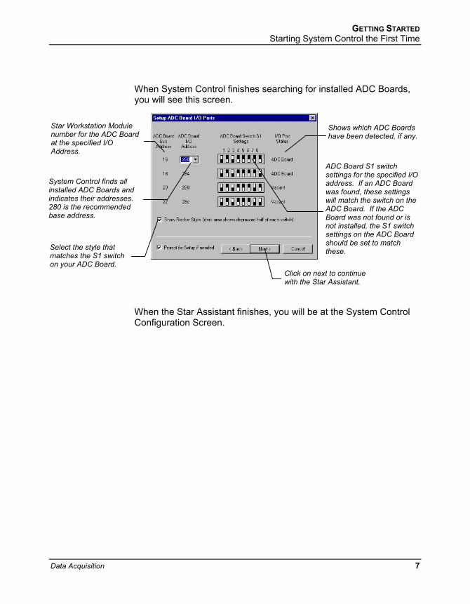
When System Control finishes searching for installed ADC Boards, you will see this screen.
Star Workstation Module number for the ADC Board at the specified I/O Address.
Shows which ADC Boards have been detected, if any.
ADC Board S1 switch settings for the specified I/O address. If an ADC Board was found, these settings will match the switch on the ADC Board. If the ADC Board was not found or inot installed, the S1 switsettings on the ADC Board should be set to match these.
s ch
System Control finds all installed ADC Boards and indicates their addresses. 280 is the recommended base address.
Select the style that matches the S1 switch on your ADC Board.
Click on next to continue with the Star Assistant.
When the Star Assistant finishes, you will be at the System Control Configuration Screen.
Data Acquisition 7

Configuring an Instrument
Modules and Instruments Defined System Control communicates with hardware modules that are used to perform chromatography. When you group these modules together in System Control (and physically connect together any necessary cables and plumbing), they form an instrument. All modules in an instrument are synchronized to run on the same time base. For Star Data Acquisition Workstation, the only modules that are installed are ADC Boards. An instrument, therefore, would consist of one or more ADC Boards electrically connected to your detector output(s).
Elements of the Configuration Screen
Instrument Parameters -- Instrument Name Operator Name Instrument status
AutoStart Module area. Place the ADC Board Module icon in this box if you want the ADC Board to provide the Start signal to the chromatograph. If the ADC Board receives a Start signal from the chromatograph, do NOT put it in this box.
Module icon showing that ADC Board Module 16 has been configured to Instrument #1.
Click on this button to enter or change the Instrument Name, Operator Name, and Maximum allowable error count.
Instrument Window – drag modules from the available module area to add them to an instrument. Double-click in this area to view the System Control Status and Control Window for this instrument. For the Star Data Acquisition Workstation Single Instrument, there will only be one instrument window shown on this screen.
Modules that have logged in and are available for configuration into an instrument are displayed here.
8 03-914729-00:4

GETTING STARTED The Instrument Window
Setting Instrument Parameters
When the maximum number of non-fatal errors is exceeded during automation, the automation sequence halts. Setting this value to zero disables this feature.
The instrument name appears on reports and in the instrument window.
The operator name appears on reports. You are optionally prompted for this
information when you start an automated sequence of injections or recalculations.
The Instrument Window Once you have configured your instruments, you may view any instrument window.
Double-click in this area or select the instrument from the Instrument menu to view the System Control Status and Control Window for this instrument.
The instrument window allows you to monitor the status of all modules assigned to the instrument, perform injections of one or more samples, and perform batch recalculations.
Data Acquisition 9

Elements of the Instrument Window
Instrument Status display shows Operator and Instrument Names, free disk space, connected modules, open method, and the number of injections, calculations, recalculations, and reports.
ADC Board Status and Control Window
Quick Link button for the selected Data File.
List of the most recently used Data Files. Data Files are added to this list box as they are generated. When a Data File is selected, its name appears on the Quick Link button above. This Quick Link button provides access to additional operations for the selected Data File.
Real Time Chromatogram Displays
System Control Instrument Window positions are remembered the next time you start System Control.
Displaying ADC Board Status and Control Window
If the Status and Control Windows for the modules configured in the instrument are not currently displayed, you can select Show Module Windows from the Windows menu.
10 03-914729-00:4

GETTING STARTED The Instrument Window
Configuring the ADC Board Status and Control Window Method parameters and synchronization signals can be configured in the ADC Board window.
Change the Method endtime.
Enable or disable synchronization signals.
Show only the chromatogram display.
Select the channels to view.
Edit the active Method.
Configuring the Real-Time Chromatogram Display All detectors installed on the 3800 GC display their chromatographic signals in real time. Configuration of the chromatogram display for all detectors is the same.
Enable/disable the Auto Scale feature.
Enable/disable the cursor display. Use these buttons to move
between stored scalings. Select the background color for the display.
Hide/unhide the Toolbar.
Set both the amplitude and time axes to full scale.
Set the amplitude axis to full scale.
Set the time axis to full scale.
Data Acquisition 11
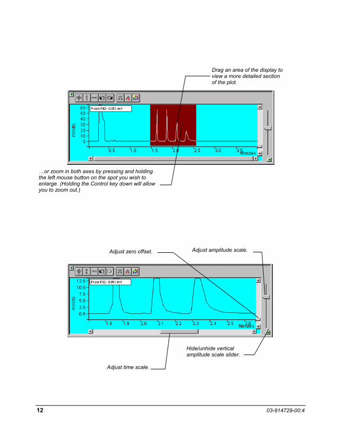
Drag an area of the display to view a more detailed section of the plot.
…or zoom in both axes by pressing and holding the left mouse button on the spot you wish to enlarge. (Holding the Control key down will allow you to zoom out.)
Adjust amplitude scale. Adjust zero offset.
Hide/unhide vertical amplitude scale slider.
Adjust time scale.
12 03-914729-00:4

GETTING STARTED The Instrument Window
Documenting Module Information You may wish to document the configuration of your modules, their installation and most recent service dates, and other information pertinent to your instrument. To do so, use the Module Information Editor accessed from the Edit menu in the instrument window.
Click on the module window to give it the focus.
Select Edit Module Info.
Data Acquisition 13

The Module Information Editor window is displayed.
You may add and edit sections and items in sections.
Select Help for details on creating and editing module information.
The injections value is updated each time an injection is performed.
Click on Done to close the window.
Module information is copied into Data Files generated after injections and can be included in the Run Log portion of the results report.
14 03-914729-00:4

Ethernet Communication Setup
This section describes the procedure for configuring your computer for use with the Star 800 MIB that communicates with the Star Workstation over a standard 10BaseT Ethernet connection. Your system can easily be expanded from a single module on a single Star Workstation configuration to multiple modules on a single Star Workstation. In a fully networked lab, it is possible to have several Star 800 MIBs connected to any one of several Star Workstation systems located anywhere on the network.
The term Ethernet refers to the cables and interface cards that are used to connect devices on the network. Several types of Ethernet cables exist, and if you are connecting your Star 800 MIB to an existing Ethernet network, you will need to use cables compatible with 10BaseT Ethernet connections. Generally these will be Ethernet category 3 or Ethernet category 5 cables with RJ45 connectors.
Data Acquisition 15

What Do I need to Know about Networks The Star 800 MIB uses TCP/IP (Transmission Control Protocol / Internet Protocol) to communicate over the Ethernet network. Ethernet is a set of hardware specifications that govern the way a device is connected to the network. This section of the manual describes the Ethernet connections used to connect these modules to Star Workstations.
The term TCP/IP refers to the software protocol that allows various devices to communicate with each other over a network. Communications over the Internet and the World Wide Web use TCP/IP. Since the Star 800 MIB use TCP/IP to communicate with the Star Workstation, the Star Workstation PC and the Star 800 MIB need to be given unique IP addresses—the addresses that are used to identify each networked TCP/IP device. The process used to assign IP addresses to the PC and to the Modules is also covered in this section of the manual.
Isolated Network If you have one Star 800 MIB to connect directly to the Star Workstation PC and the Star Workstation PC is NOT connected to a company network, then you may connect your Star Workstation and Star 800 MIB directly to each other using the Ethernet crossover cable supplied with the Star 800 MIB.
Star 800 MIB
Star Workstation
Ethernet Crossover Cable p/n 03-933511-01
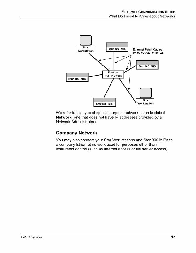
If you want to connect several Star 800 MIBs to one or more Star Workstations, then you will need to use an Ethernet 10BaseT hub or switch and Ethernet Category 3 or 5 patch cables to connect the modules and the Star Workstation PCs to the Ethernet hub or switch.
16 03-914729-00:4
ETHERNET COMMUNICATION SETUP What Do I need to Know about Networks
Star Workstation
Star Workstation
Star 800 MIB
Star 800 MIB
Star 800 MIB P S 520
Star 800 MIB
Ethernet Patch Cables p/n 03-926129-01 or -02
Ethernet Hub or Switch
We refer to this type of special purpose network as an Isolated Network (one that does not have IP addresses provided by a Network Administrator).
Company Network You may also connect your Star Workstations and Star 800 MIBs to a company Ethernet network used for purposes other than instrument control (such as Internet access or file server access).
Data Acquisition 17

Company Ethernet Network
Star Workstation
Star Workstation
Star Workstation
Star 800 MIB
Star 800 MIB
Star 800 MIB
Ethernet Hub or S i h
Ethernet Patch Cables
p/n 03-926129-01 or -02
Star 800 MIB
Star 800 MIB
Star 800 MIB
Ethernet Hub or S i h
Ethernet Patch Cables p/n 03-926129-01 or -02
Uplink connection to Company Network
Uplink connection to Company Network
Star 800 MIB
Star 800 MIB
We refer to this type of multi-purpose network as a Company Network, and a Network Administrator in your company will typically manage it. If this is the case, then some of the settings needed to configure your Star 800 MIB and Star Workstation PC will need to be provided by your Network Administrator.
The Star 800 MIB is provided its IP address either by the BOOTP server included with Star Workstation or by BOOTP software running on your network. The software used to send IP addresses to TCP/IP devices is called a BOOTP Server (Bootstrap Protocol Server). You will see the term BOOTP Server mentioned in this manual. If you are connecting your modules and Star Workstation to a company network, your Network Administrator should be made aware that the Star 800 MIB would require a BOOTP Server for IP address assignment.
18 03-914729-00:4

ETHERNET COMMUNICATION SETUP Where to Begin
Where to Begin Before beginning the configuration process, you should know whether you will be attaching your Star Workstation PC, the Star 800 MIB to a company network (as described in the previous section) or as an isolated network only used for instrument control. If you have a Network Administrator on site, you may wish to ask which configuration is recommended.
Use this information to determine the order in which you should read the following sections.
“Setting the Network Properties for Isolated Network” describes the procedure for configuring the TCP/IP parameters of your Star Workstation PC for use with No Company Network.
“Setting the Network Properties for Company Network” describes the procedure for configuring the TCP/IP parameters of your Star Workstation PC for use on a Company Network.
“Setting the Star WS BOOTP Server to Assign IP Addresses” describes the process of getting the Star Workstation to assign IP Addresses for the modules connected to the network.
“Adding Star 800 MIB to Instruments in System Control” describes the process of configuring and adding the modules to instruments.
Setting the Network Properties for Isolated Network Note: The following section describes a procedure specific to Windows 2000.
If you are running Windows NT 4.0 or Windows 98, the Windows and dialog boxes shown will differ from those you see on your system, but the procedure described here is essentially the same as the one for Windows NT 4.0 or Windows 98.
Data Acquisition 19

If you will be connecting your Star Workstation PC directly to one or more Star 800 MIB modules, with no connection to the company network, then you can use the following network properties on your PC:
Subnet mask 255.0.0.0
Gateway
DNS
To access the TCP/IP network properties click on the Windows Start button and select Settings Network and Dial-up Connection Local Area Connection Properties.
From the installed component list, click on the TCP/IP protocol and select properties. Since your Star Workstation PC is only connected to the Star 800 MIB, you can set the IP Address to any value, for example 10.2.128.1.
20 03-914729-00:4

ETHERNET COMMUNICATION SETUP Setting the Network Properties for Isolated Network
If the TCP/IP is not listed in the list of Network components, then click on the Install button and select Protocol from the list of Network Components Type, and select Microsoft as the manufacturer and TCP/IP as the Protocol.
Data Acquisition 21

If your isolated network contains multiple Star 800 MIBs, and Star Workstation PCs or a combination of these, then each device on the network will need a unique IP address assigned to it. You will need to keep track of which IP addresses have been used to avoid assigning duplicates.
Note: After making changes to the network properties in the PC, save the changes and then shutdown and power off the PC. This will ensure that the Ethernet board is reset and communication is restarted with the new properties.
Setting the Network Properties for a Company Network If you will be connecting your Star Workstation PC to your company network, you should contact your Network Administrator to obtain the static IP addresses for each device, the gateway, domain, DNS settings, and WINS settings that should be used. Note that each Workstation PC must have a unique IP address.
To access the TCP/IP network properties click on the Windows Start button and select Settings Network and Dial-up Connection Local Area Connection Properties. The following is only an example of the Network TCP/IP properties for the Star Workstation PC when connected to a company network.
22 03-914729-00:4

ETHERNET COMMUNICATION SETUP Setting the Star WS BOOTP Server to Assign IP Addresses
Setting the Star WS BOOTP Server to Assign IP Addresses If you are using a Company Network and the Network Administrator has a BOOTP Server on the network that will be providing the IP Addresses for the chromatography instruments connected to the network, you should skip to the next section. For all other installations, choose one Star Workstation PC to be the BOOTP server.
Note: It is good practice to have only one BOOTP server on a network.
1. Power up your Star Workstation PC that will be the BOOTP server. The Star 800 MIBs connected to the network should still be powered down.
2. When System Control has started for the first time, the Star Assistant Communication Configuration Wizard will appear to guide you through the Ethernet communication setup.
Data Acquisition 23

Otherwise, start System Control and choose Setup Ethernet Communications from the Instrument drop down menu. Click on the Next button. The Setup Ethernet Ports dialog will display a table of module Addresses (44, 45, 46, 47), Module Type, and IP Address or Domain Name.
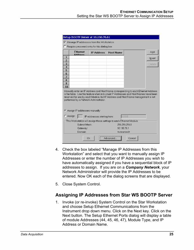
3. Click on the Setup button located at the right side of the window. The “Setup BOOTP Server” dialog box will display a table with the headings Ethernet Address, IP Address, and Host Name.
24 03-914729-00:4
ETHERNET COMMUNICATION SETUP Setting the Star WS BOOTP Server to Assign IP Addresses
4. Check the box labeled “Manage IP Addresses from this Workstation” and select that you want to manually assign IP Addresses or enter the number of IP Addresses you wish to have automatically assigned if you have a sequential block of IP addresses to assign. If you are on a Company Network, your Network Administrator will provide the IP Addresses to be entered. Now OK each of the dialog screens that are displayed.
5. Close System Control.
Assigning IP Addresses from Star WS BOOTP Server 1. Invoke (or re-invoke) System Control on the Star Workstation
and choose Setup Ethernet Communications from the Instrument drop down menu. Click on the Next key. Click on the Next button. The Setup Ethernet Ports dialog will display a table of module Addresses (44, 45, 46, 47), Module Type, and IP Address or Domain Name.
Data Acquisition 25

2. Click on the Setup button located at the right side of the window. The Setup BOOTP Server dialog box will display a table with the headings Ethernet Address, IP Address, and Host Name.
Verify that the PC IP address in the title bar and Ethernet settings at the bottom of the dialog box are correct before proceeding.
3. Power-up one of your Star 800 MIBs.
4. Within a couple of minutes, the Ethernet address will appear in the table for the Star 800 MIB that you just turned on. If you are in a network environment, this could take longer. If you have chosen to manually assign IP Addresses, you should enter one now, otherwise, it should appear automatically in this dialog box. If you are on a Company Network, your Network Administrator should provide this IP address.
5. Enter a descriptive name in the Host Name field for your Star 800 MIB. If you are on a Company Network, your Network Administrator may provide this name.
6. Repeat steps 3, 4, and 5 for each Star 800 MIB connected to your network.
7. When all of the chromatographic devices have been powered up and had their IP Address and Host Name entered into the table, click OK.
The following is an example for Isolated Network IP addresses that were assigned to a Star 800 MIB. These IP addresses are not provided by a Network Administrator, However, the IP addresses must be on the same segment as your Star Workstation PC that was assigned an IP address of 10.2.128.1 in this section of the manual.
26 03-914729-00:4

ETHERNET COMMUNICATION SETUP Setting the Star WS BOOTP Server to Assign IP Addresses
The following is an example for Company Network IP addresses that were assigned to a Star 800 MIB. A Network Administrator provided these IP addresses.
Data Acquisition 27

Allow a couple of minutes for the Star 800 MIB to get their IP Addresses and finish booting.
Adding Star 800 MIB to Instruments in System Control Once you have configured your Star Workstation computer and the Star 800 MIB for network communication, you may select up to four Ethernet modules to be controlled from each Star Workstation. If it is not already running, start System Control. The Star Assistant Communication Configuration Wizard will be displayed if you have not yet configured your Star 800 Ethernet connections. Click on the Next button to advance to the Setup Ethernet Ports dialog box.
1. In the Setup Ethernet Ports Dialog box, click on the Module Type drop down box for one of the lines and select 800.
28 03-914729-00:4

ETHERNET COMMUNICATION SETUP Adding Star 800 MIB to Instruments in System Control
2. Press the TAB key and type in the IP Address or Host Name of the Star 800 MIB that you wish to control.
3. Click on the “Config…” button located to the left of the Star 800 MIB that you want to configure. The Assign ADC Channels dialog box will be displayed. Each Star 800 MIB channel can be configured for the analog signal level and synchronization signal polarity.
Data Acquisition 29

4. The top half of this dialog box is a table for the settings of the analog and synchronization signals. The different rows allow the configuration of analog channels connected to different instruments. ONLY the analog channels connected to detectors in the same instrument should have their settings on the same row. There will be one 800 MIB icon created for each row that has an analog signal setting. Multiple analog signal settings in the same row are different channels in the same ADCB.
Select the analog input signal range from the drop down box for each channel that is being used.
5. Next select the Start In and System Ready Out synchronization signal settings from the drop down boxes for each row that has channel entry. The bottom half of this dialog box allows the optional serial ports to be configured. For Varian detectors, Start In should be set to “when closing” and Ready Out should be set to “when closed”.
6. When the entries are complete, click on Save.
7. Click OK on the dialog box reminding you to restart System Control for the changes to be implemented.
8. Click OK to close the Setup Ethernet dialog box.
9. Close and restart System Control.
10. When System Control is restarted, 800 MIB icons corresponding to the analog channels just configured for the Star 800 MIB will appear. These icons can now be configured into the instruments and used like any other module in Star Workstation.
30 03-914729-00:4

Using the Star 800 MIB
This section describes the use of the Star 800 Module Interface Box (MIB) with the Star Data Acquisition Workstation. For information on the operation of the Star Workstation, please refer to the earlier sections of this manual.
Note: For information on the Star 800 MIB setup and configuration, please refer to the Ethernet Communication Setup section of this manual.
A maximum of four Star 800 MIBs can be configured in one computer for use with the Star Chromatography Workstation software.
Connecting to an Instrument The Star 800 MIB provides up to four channels of analog-to-digital signal conversion (ADC) with chromatographic module synchronization contacts for each analog channel. The ADC channels can be used to collect data from any chromatographic detector that provides a voltage output signal of less than 10 volts. The synchronization signals are contact closures for START IN and READY OUT signals that can be used to synchronize the Star Chromatography Workstation operation with the chromatographic modules connected to it. The Star 800 MIB can also provide a serial interface to 3400 GCs, 3600 GCs, and standalone 8200/SPME AutoSamplers when equipped with the optional serial interface board.
All of the instrument interface connections are on the right side of the Star 800 MIB.
Data Acquisition 31

Output signals from the PS-310, PS-320, PS-340, PS-345, PS-350 and PS-363 can be connected to the ADC channels of the Star 800 MIB for data processing by the Star Workstation.
Analog Signals The analog signals connect to the Star 800 MIB using a 4-pin mini DIN (round) connector that attaches to one of the analog signal input ports in the middle of the right side of the Star 800 MIB. Depending on how the Star 800 MIB was ordered, there will either be two or four analog input ports on the Star 800 MIB.
Analog cables are sold separately and they are available with various end configurations to match the Varian detector analog output connectors. Included with each analog signal cable is the corresponding synchronization cables. The following analog signal cables are available and the cables appropriate for your installation should have been purchased and be available to complete this installation.
32 03-914729-00:4
USING THE STAR 800 MIB Connecting to an Instrument
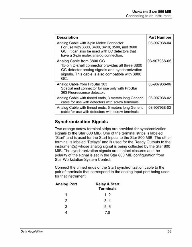
Description Part Number Analog Cable with 3-pin Molex Connector
For use with 3300, 3400, 3410, 3500, and 3600 GC. It can also be used with LC detectors that have a 3-pin molex analog connection.
03-907938-04
Analog Cable from 3800 GC 15-pin D-shell connector provides all three 3800 GC detector analog signals and synchronization signals. This cable is also compatible with 3900 GC.
03-907938-05
Analog Cable from ProStar 363 Special end connector for use only with ProStar 363 Fluorescence detector.
03-907938-06
Analog Cable with tinned ends, 3 meters long Generic cable for use with detectors with screw terminals.
03-907938-02
Analog Cable with tinned ends, 5 meters long Generic cable for use with detectors with screw terminals.
03-907938-03
Synchronization Signals Two orange screw terminal strips are provided for synchronization signals to the Star 800 MIB. One of the terminal strips is labeled “Start” and is used for the Start Inputs to the Star 800 MIB. The other terminal is labeled “Relays” and is used for the Ready Outputs to the instrument(s) whose analog signal is being collected by the Star 800 MIB. The synchronization signals are contact closures and the polarity of the signal is set in the Star 800 MIB configuration from Star Workstation System Control.
Connect the tinned ends of the Start synchronization cable to the pair of terminals that correspond to the analog input port being used for that instrument.
Analog Port Relay & Start Terminals
1 2 3 4
1, 2 3, 4 5, 6 7,8
Data Acquisition 33
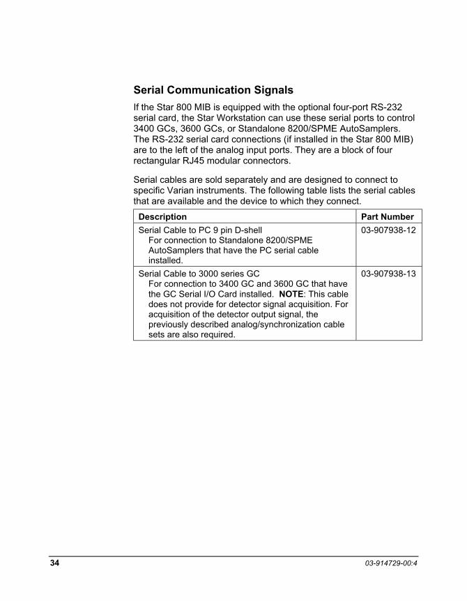
Serial Communication Signals If the Star 800 MIB is equipped with the optional four-port RS-232 serial card, the Star Workstation can use these serial ports to control 3400 GCs, 3600 GCs, or Standalone 8200/SPME AutoSamplers. The RS-232 serial card connections (if installed in the Star 800 MIB) are to the left of the analog input ports. They are a block of four rectangular RJ45 modular connectors.
Serial cables are sold separately and are designed to connect to specific Varian instruments. The following table lists the serial cables that are available and the device to which they connect.
Description Part Number Serial Cable to PC 9 pin D-shell
For connection to Standalone 8200/SPME AutoSamplers that have the PC serial cable installed.
03-907938-12
Serial Cable to 3000 series GC For connection to 3400 GC and 3600 GC that have the GC Serial I/O Card installed. NOTE: This cable does not provide for detector signal acquisition. For acquisition of the detector output signal, the previously described analog/synchronization cable sets are also required.
03-907938-13
34 03-914729-00:4
USING THE STAR 800 MIB The Star 800 MIB Status Window
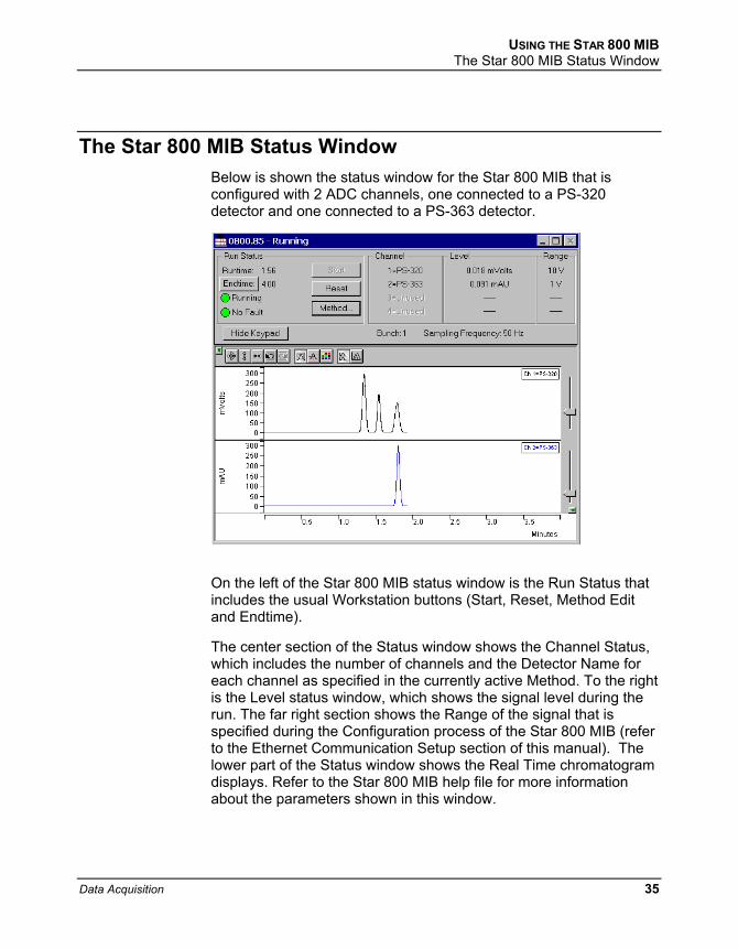
The Star 800 MIB Status Window Below is shown the status window for the Star 800 MIB that is configured with 2 ADC channels, one connected to a PS-320 detector and one connected to a PS-363 detector.
On the left of the Star 800 MIB status window is the Run Status that includes the usual Workstation buttons (Start, Reset, Method Edit and Endtime).
The center section of the Status window shows the Channel Status, which includes the number of channels and the Detector Name for each channel as specified in the currently active Method. To the right is the Level status window, which shows the signal level during the run. The far right section shows the Range of the signal that is specified during the Configuration process of the Star 800 MIB (refer to the Ethernet Communication Setup section of this manual). The lower part of the Status window shows the Real Time chromatogram displays. Refer to the Star 800 MIB help file for more information about the parameters shown in this window.
Data Acquisition 35

Star 800 MIB Method
From the Star Workstation Method Builder window select the Star 800 MIB Set Condition Method section. The Parameter Entry pan will be displayed. The top section of the window contains data acquisition and display settings. The table at the bottom of the window allows entry of Star 800 MIB labeling and scaling information including a Data Units column to specify the Units for the detector signal that is being digitized. Please refer to the Method Editor Help files for more information on the Star 800 MIB Method section.
36 03-914729-00:4

Building Methods
Overview In the Getting Started section, you configured your hardware for an instrument and opened the System Control Window for the instrument. At this point, you could simply inject a sample, as described in the following sections. However, it is not likely that the default Method will have the Method settings that are appropriate for your analysis. Therefore, the default Method will need to edited to enter the settings appropriate for your analysis. Method Builder is used to view and edit Methods. It can be accessed from:
This button on the Star Toolbar opens Method Builder and prompts you to create a new Method or open an existing one.
This button on the Star Toolbar allows you to view and edit the Method file shown on the button.
This button on the System Control Toolbar allows you to view and edit the Method file shown on the button.
Data Acquisition 37

Using Star Assistant to Create a new Method If you click on the Method Builder button on the Star Toolbar, you will get this dialog box.
If you choose Create a New Method File, the Star Assistant Wizard will guide you in building this new Method.
38 03-914729-00:4
BUILDING METHODS Using Star Assistant to Create a new Method
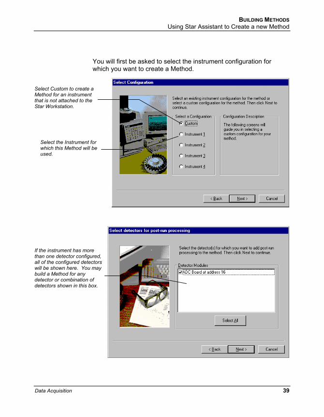
You will first be asked to select the instrument configuration for which you want to create a Method.
Select Custom to create a Method for an instrument that is not attached to the Star Workstation.
Select the Instrument for which this Method will be used.
If the instrument has more than one detector configured, all of the configured detectors will be shown here. You may build a Method for any detector or combination of detectors shown in this box.
Data Acquisition 39

For each detector in the Method, you will be asked to select the channels on which post-run processing will be performed.
When you have selected the data channels and type(s) of post-run processing to be run for each detector, the Star Assistant will create a Method containing all of the sections that are needed to control the hardware, collect data and do the post-run processing specified. These Method sections will contain default values for all of the parameters. These parameters will need to be edited to match your analysis.
40 03-914729-00:4

BUILDING METHODS The Method Builder Window
The Method Builder Window
Title Bar
Menu Bar
Toolbar
This navigation window shows the overall structure of the Method, its sections, and subsections. The branches can be expanded by clicking on the plus sign or contracted by clicking on the minus sign to show the desired level of detail.
The parameters window shows the parameters for the highlighted item in the navigation window. Method parameters are viewed and edited in this window.
Detailed information about the menu items and Toolbar buttons can be found in the on-line help.
Data Acquisition 41
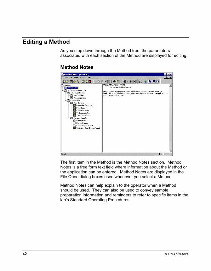
Editing a Method As you step down through the Method tree, the parameters associated with each section of the Method are displayed for editing.
Method Notes
The first item in the Method is the Method Notes section. Method Notes is a free form text field where information about the Method or the application can be entered. Method Notes are displayed in the File Open dialog boxes used whenever you select a Method.
Method Notes can help explain to the operator when a Method should be used. They can also be used to convey sample preparation information and reminders to refer to specific items in the lab’s Standard Operating Procedures.
42 03-914729-00:4
BUILDING METHODS Editing a Method
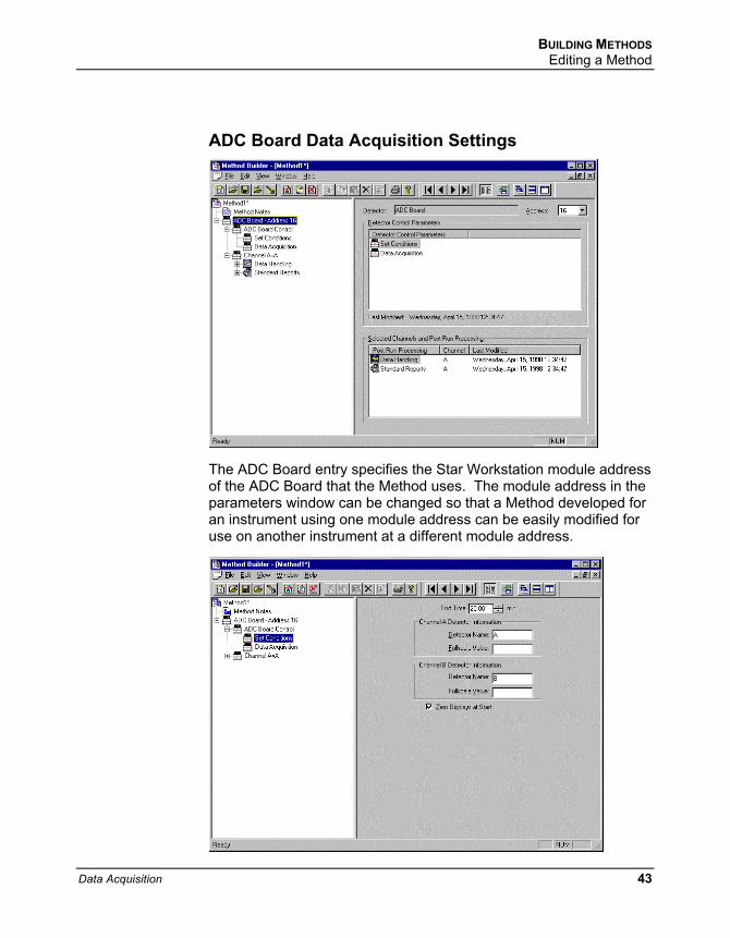
ADC Board Data Acquisition Settings
The ADC Board entry specifies the Star Workstation module address of the ADC Board that the Method uses. The module address in the parameters window can be changed so that a Method developed for an instrument using one module address can be easily modified for use on another instrument at a different module address.
Data Acquisition 43
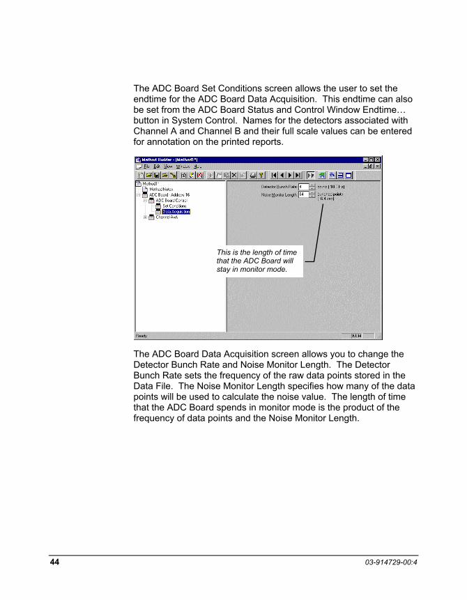
The ADC Board Set Conditions screen allows the user to set the endtime for the ADC Board Data Acquisition. This endtime can also be set from the ADC Board Status and Control Window Endtime… button in System Control. Names for the detectors associated with Channel A and Channel B and their full scale values can be entered for annotation on the printed reports.
This is the length of time that the ADC Board will stay in monitor mode.
The ADC Board Data Acquisition screen allows you to change the Detector Bunch Rate and Noise Monitor Length. The Detector Bunch Rate sets the frequency of the raw data points stored in the Data File. The Noise Monitor Length specifies how many of the data points will be used to calculate the noise value. The length of time that the ADC Board spends in monitor mode is the product of the frequency of data points and the Noise Monitor Length.
44 03-914729-00:4

BUILDING METHODS Editing a Method
Post-run Processing
Multichannel detectors can have post-run processing sections for any or all of their channels. For the Method shown above, post-run processing has only be chosen for ADC Board Channel A. The post-run processing for Channel A includes both Data Handling (peak detection and integration) and Standard Reports (numerical results and chromatogram).
Data Acquisition 45

The Data Handling section has parameter pages for Integration Parameters, Peak Table entries, Calibration Setup, Verification Setup and Time Events (integration control parameters). For the initial setup of a Method the default values are usually a good starting place. For information on these Data Handling parameters and setting them for your application, please refer to the Data Handling and Reports Operation Manual.
46 03-914729-00:4
BUILDING METHODS Editing a Method
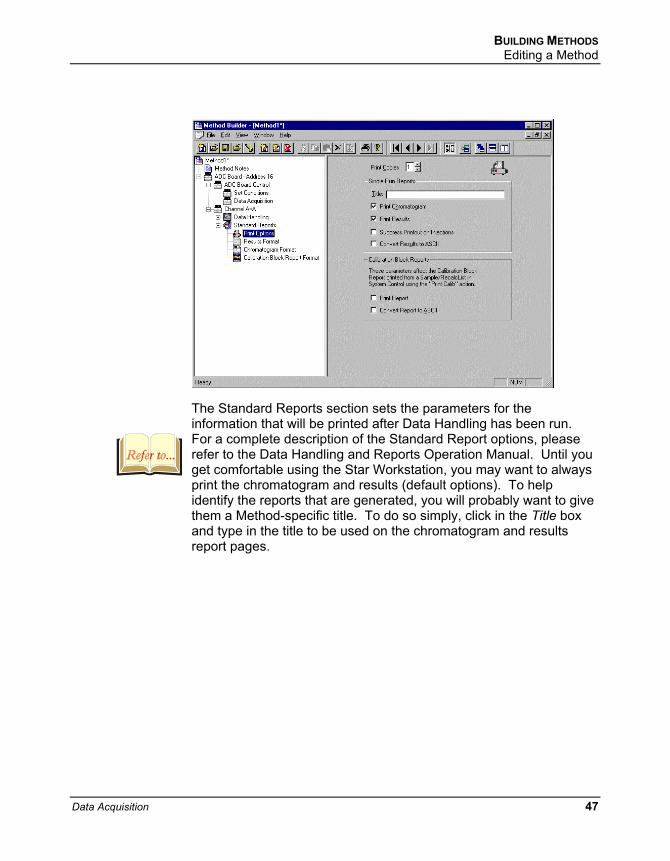
The Standard Reports section sets the parameters for the information that will be printed after Data Handling has been run. For a complete description of the Standard Report options, please refer to the Data Handling and Reports Operation Manual. Until you get comfortable using the Star Workstation, you may want to always print the chromatogram and results (default options). To help identify the reports that are generated, you will probably want to give them a Method-specific title. To do so simply, click in the Title box and type in the title to be used on the chromatogram and results report pages.
Data Acquisition 47

The Results Format page controls the format of the results table, the result units to be printed in the Amount column header and the number of decimal digits to print for the calculated amounts. It also controls what additional information is appended to the end of the results report.
48 03-914729-00:4

BUILDING METHODS Editing a Method
The Chromatogram Format page controls the formatting of the printed chromatogram. When the defaults are used, the chromatogram for the complete run will be printed and autoscaled to fit on one page. You may only want to print the portion of the chromatogram that contains the peaks of interest. This may be done by changing the start and end times to bracket the period of interest. Auto Scale is often turned off and a fixed attenuation and zero offset chosen so that printed chromatograms from several runs may be visually compared. For more information about the Chromatogram Format parameters, please refer to Data Handling and Operation Reports Manual.
Data Acquisition 49

The Startup Method When you start System Control and display an Instrument Window, the last active Method for that instrument is activated. When System Control is started, it will return to the initial settings in the Method that was last used on the instrument.
To change Methods, simply click on the activate Method button on the System Control Toolbar or choose New Method from the File menu.
Editing Methods from the ADC Board Status and Control Window
The ADC Board Status and Control Window Method… button allows you to directly edit the active Method corresponding to that ADC Board. When you click on this button, Method Builder is opened with active Method loaded and the corresponding ADC Board Instrument Control section selected. You can then edit that section or any other section of the Method as described previously.
Once you have edited the Method and closed the Method Builder window, you are prompted to reactivate the Method. Reactivating the Method downloads the changes to the ADC Board.
Changing Method Endtime from the ADC Board Status and Control Window
The ADC Board Status and Control Window Endtime… button allows you to immediately change the endtime of the active Method Instrument Control section corresponding to that ADC Board. This is useful if you wish to extend a run while the run is in progress. Changing the endtime in this manner updates the endtime in the stored Method. This endtime will then be used until the Method endtime is changed by again using the Endtime… button or editing the Method.
50 03-914729-00:4
BUILDING METHODS Importing Method Sections
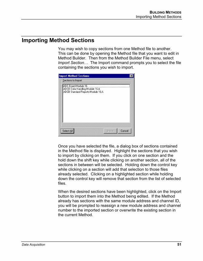
Importing Method Sections You may wish to copy sections from one Method file to another. This can be done by opening the Method file that you want to edit in Method Builder. Then from the Method Builder File menu, select Import Section… The Import command prompts you to select the file containing the sections you wish to import.
Once you have selected the file, a dialog box of sections contained in the Method file is displayed. Highlight the sections that you wish to import by clicking on them. If you click on one section and the hold down the shift key while clicking on another section, all of the sections in between will be selected. Holding down the control key while clicking on a section will add that selection to those files already selected. Clicking on a highlighted section while holding down the control key will remove that section from the list of selected files.
When the desired sections have been highlighted, click on the Import button to import them into the Method being edited. If the Method already has sections with the same module address and channel ID, you will be prompted to reassign a new module address and channel number to the imported section or overwrite the existing section in the current Method.
Data Acquisition 51
Deleting Method Sections To remove sections from a Method open the Method containing the sections you wish to remove in Method Builder. Click on the Delete Section button on the Method Builder Toolbar or select Delete Section from the File menu. A dialog box of sections contained in the Method file is displayed. Highlight the sections that you wish to delete by clicking on them. If you click on one section and the hold down the shift key while clicking on another section, all of the sections in between will be selected. Holding down the control key while clicking on a section will add that selection to those files already selected. Clicking on a highlighted section while holding down the control key will remove that section from the list of selected files.
When the desired sections have been highlighted, click on the Delete button to delete them from the Method being edited. You will be prompted to confirm that you want to delete each section before it is deleted.
Printing the Method To print a Method from Method Builder, click on the Print button on the Toolbar and select the Method section or sections to be printed. The active Method can also be printed from the System Control Toolbar and the Star Toolbar. Click on the Active Method Options button on the System Control Toolbar or on the Method Operations button on the Star Toolbar and select Print Method.
Password Protecting a Method A Method can be password protected from changes by clicking on the Set Password button on the Method Builder Toolbar or selecting Set Password from the File menu. Enter the password and then re-enter it to verify that it was not mistyped. After a Method has been password protected, the password will be required to save changes to the Method.
Once a Method is password protected, it can be activated and used for instrument control and data acquisition. It can also be viewed from Method Builder. Only the saving of changes to the Method will be inhibited unless the correct password is entered.
52 03-914729-00:4

Injecting a Single Sample
By now you should have your instrument configured and a basic Method built for data acquisition. If this hasn’t been done, please refer to the previous sections for instructions on doing this.
Using the Inject Single Sample Dialog Box You can inject a single sample from System Control by using the Inject Single Sample dialog box.
or by clicking on the Inject Single Sample button on the toolbar.
Display the Inject Single Sample dialog by selecting it from the Inject menu …
Data Acquisition 53

The Inject Single Sample dialog box is displayed.
Enter notes about the sample. Refer to the Specifying Data Handling Parameters section of this manual.
Specifies the number of injections of this sample.
Enter information about the sample.
Click Inject to start the run.
The fields in the table change depending on the type of sampling device configured in the instrument.
Change the location and name of the Data Files.
Select the Method to use for the run.
Specifying the Data File Name and Path Data File names can be up to 255 characters long. Sample ID, injection date, module name, and injection number can be embedded in the file name making the Data File name correlate with each sample injection. When you click on the Data Files… button, the Data Files Generation dialog box is displayed. This dialog box allows you to select the path and the file name specification for the data file displayed.
54 03-914729-00:4

INJECTING A SINGLE SAMPLE Specifying the Data File Name and Path
The left side of the Data File Generation dialog box allows you to select the drive letter and subdirectory (path) where the data files are to be stored. The default directory is the data subdirectory of your Star directory.
The right side of this dialog box allows you to create a file name specification. You can combine text entry with the “%” variable symbols shown to specify file names that contain sample injection specific information. An example of the file name is dynamically updated as you type in the file name specification. This makes it easy to see how a Data File created with this file name specification would appear.
Data Acquisition 55

Specifying Per-Sample Data Handling Parameters Most Data Handling parameters are specified in the Method used during the injection. Some parameters may vary on a per-sample basis, and are therefore specified when you perform the injection.
The following Data Handling parameters can be specified on a per-sample basis:
Unidentified Peak Factor
Multiplier
Divisor
Amount Standard when one Internal Standard is being used
Refer to the Data Handling and Reports Operation Manual for a brief description of these parameters.
Refer to the Regulatory Compliance Manual for a complete description of how these parameters are used to calculate results.
Not only can you specify these parameters on a per-sample basis, but you can specify them on a per-detector channel basis. This is useful if, for example, you have an ADC Board with channel A and channel B connected to two different detectors on a GC. In addition, if you are using multiple internal standards, you can also specify their amounts on a per sample and per detector channel basis.
56 03-914729-00:4

INJECTING A SINGLE SAMPLE Specifying Per-Sample Data Handling Parameters
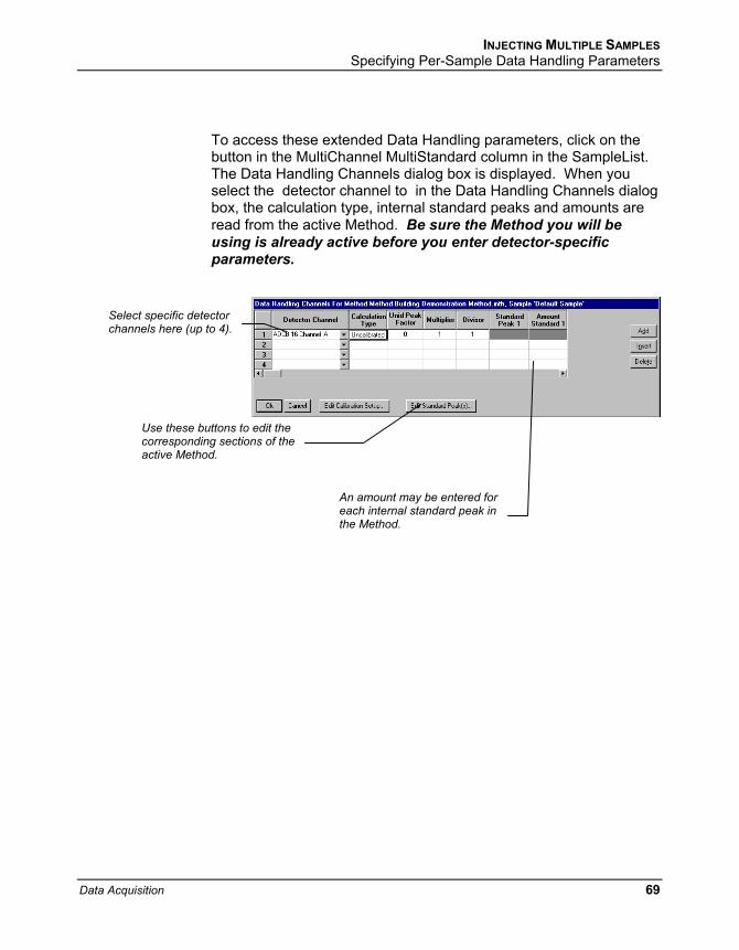
To access these extended Data Handling parameters, click on the button in the Multi-Channel Multi-Standard column in the Inject Single Sample dialog box. The Data Handling Channels dialog box is displayed. When you select the detector channel to in the Data Handling Channels dialog box, the calculation type, internal standard peaks and amounts are read from the active Method. Be sure the Method you will be using is already active before you enter detector-specific parameters.
Select specific detector channels here (up to 4).
An amount may be entered for each internal standard peak in the Method.
Use these buttons to edit the corresponding sections of the active Method.
Data Acquisition 57

Specifying a RecalcList You can choose to create a new RecalcList, append to an existing RecalcList, or not create nor update a RecalcList. To select the RecalcList option that you want, click on the RecalcList button. The RecalcList Generation dialog box is displayed.
If you choose to create a new RecalcList, this automatically generated RecalcList will not overwrite an existing RecalcList unless you also specify “Overwrite the Recalc List each time the SampleList begins”. If a RecalcList with the same file name exists, the newly created RecalcList will have number appended to its file name to make it unique and to prevent the older RecalcList from being overwritten.
58 03-914729-00:4

INJECTING A SINGLE SAMPLE Monitoring the Status of the Run
Monitoring the Status of the Run After an injection is performed, the status of the run can be monitored in the instrument window.
Module status is shown in the status and control windows and on the toolbar.
The total number of injections completed is shown in the Instrument Status window.
Automation actions and errors are logged in the Message Log.
The chromatogram is displayed as it is acquired.
Data Acquisition 59
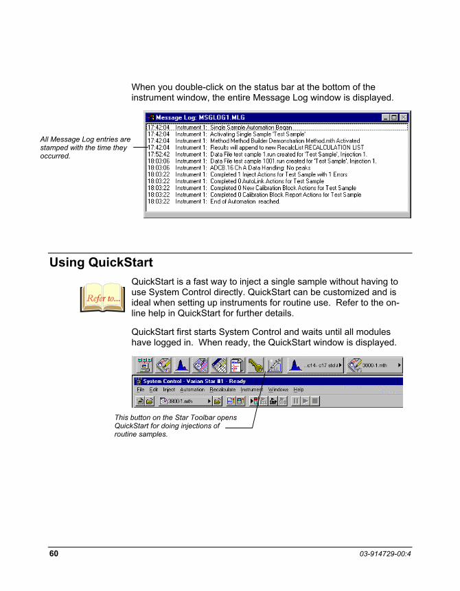
When you double-click on the status bar at the bottom of the instrument window, the entire Message Log window is displayed.
All Message Log entries are stamped with the time they occurred.
Using QuickStart QuickStart is a fast way to inject a single sample without having to use System Control directly. QuickStart can be customized and is ideal when setting up instruments for routine use. Refer to the on-line help in QuickStart for further details.
QuickStart first starts System Control and waits until all modules have logged in. When ready, the QuickStart window is displayed.
This button on the Star Toolbar opens QuickStart for doing injections of routine samples.
60 03-914729-00:4
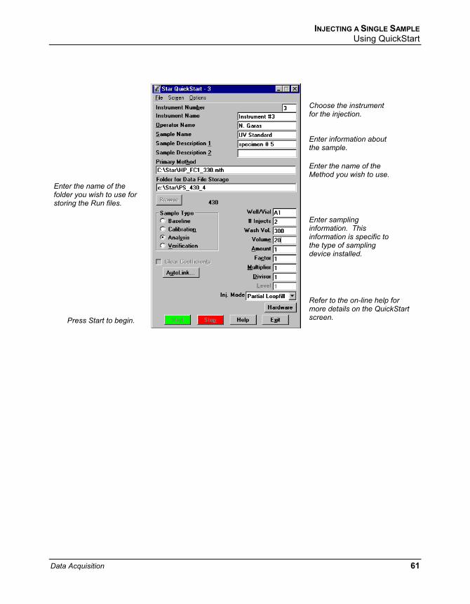
INJECTING A SINGLE SAMPLE Using QuickStart
Choose the instrument for the injection.
Enter information about the sample.
Enter the name of the Method you wish to use.
Enter the name of the folder you wish to use for storing the Run files.
Enter sampling information. This information is specific to the type of sampling device installed.
Refer to the on-line help for more details on the QuickStart screen. Press Start to begin.
Data Acquisition 61

62 03-914729-00:4

Injecting Multiple Samples
By now you should have your instrument configured and a basic method built for data acquisition. If this hasn’t been done, please refer to the previous sections for instructions on doing this.
Using a SampleList in System Control You can inject multiple samples from System Control by using the SampleList.
Choose to open either a New SampleList or an existing SampleList from the File menu...
…or by clicking on the New or Open Automation File button on the toolbar.
Data Acquisition 63

The SampleList window for the open SampleList is displayed. It contains fields that are specific to the sampling device configured in the instrument. In this case, since there is no sampling device configured, a generic SampleList is used (no vial positions or sampling options).
Spreadsheet columns can be sized by dragging their border using the left mouse button. Move columns by dragging them using the right mouse button. Right click on column headers for formatting options.
Enter notes about the sample.
Enter post-run operations to be performed.
Enter information about the samples and the injections you wish to perform.
Select the location and name for the Data Files generated by the SampleList.
Press the Begin button to start injecting samples.
Used to specify RecalcList generation options.
64 03-914729-00:4

INJECTING MULTIPLE SAMPLES Using a SampleList in System Control
When the table is scrolled to the right, the Sample Name column doesn't scroll so you can easily tell for which sample you are entering additional parameters. Commonly used data handling parameters, the amount for single internal standard calculations, the unidentified peak factor, a multiplier, and a divisor, can be entered directly into this table.
If you have more complex requirements, such as multiple internal standards or multiple detectors requiring different entries for these data handling parameters, click on the button in MultiChannel MultiStandard column.
Click here to enter extended data handling parameters.
If you need to add several similar lines to the sample list, click on the Add Lines… button. You can then enter the common information in the dialog box.
For sequentially numbered Sample names, enter the starting number and the number of entries to add to the SampleList. The Sample Names will have these numbers appended to them.
Data Acquisition 65

When you press the Begin button, you are prompted for the Method to use.
…or browse for the Method file. Enter the Method to
use for the run…
After you click on OK, the run will begin. If you are using a manual injector or a sampling device that is not controlled by the Star Workstation, you will need to start the device manually.
Specifying the Data File Name and Path Data File names can be up to 255 characters long. Sample ID, injection date, module name, and injection number can be embedded in the file name making the Data File name correlate with each sample injection. When you click on the Data Files… button, the Data Files Generation dialog box is displayed. This dialog box allows you to select the path and the file name “specification” for the data file.
66 03-914729-00:4
INJECTING MULTIPLE SAMPLES Specifying the Data File Name and Path
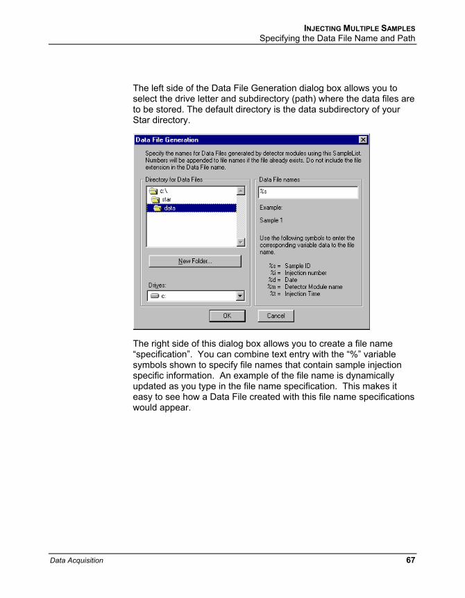
The left side of the Data File Generation dialog box allows you to select the drive letter and subdirectory (path) where the data files are to be stored. The default directory is the data subdirectory of your Star directory.
The right side of this dialog box allows you to create a file name “specification”. You can combine text entry with the “%” variable symbols shown to specify file names that contain sample injection specific information. An example of the file name is dynamically updated as you type in the file name specification. This makes it easy to see how a Data File created with this file name specifications would appear.
Data Acquisition 67

Specifying Per-Sample Data Handling Parameters Most Data Handling parameters are specified in the Method used during the injection. Some parameters may vary on a per-sample basis, and are therefore specified when you perform the injection.
The following Data Handling parameters can be specified on a per-sample basis:
Unidentified Peak Factor
Multiplier
Divisor
Amount Standard when one Internal Standard is being used
Refer to the Data Handling and Reports Operation Manual for a brief description of these parameters.
Refer to the Star Workstation Regulatory Compliance Manual for a complete description of how these parameters are used to calculate results.
Not only can you specify these parameters on a per-sample basis, but you can specify them on a per-detector channel basis. This is useful if, for example, you have an ADC Board with channel A and channel B connected to two different detectors on a GC. In addition, if you are using multiple internal standards, you can also specify their amounts on a per sample and per detector channel basis.
68 03-914729-00:4
INJECTING MULTIPLE SAMPLES Specifying Per-Sample Data Handling Parameters
To access these extended Data Handling parameters, click on the button in the MultiChannel MultiStandard column in the SampleList. The Data Handling Channels dialog box is displayed. When you select the detector channel to in the Data Handling Channels dialog box, the calculation type, internal standard peaks and amounts are read from the active Method. Be sure the Method you will be using is already active before you enter detector-specific parameters.
Select specific detector channels here (up to 4).
Use these buttons to edit the corresponding sections of the active Method.
An amount may be entered for each internal standard peak in the Method.
Data Acquisition 69

Specifying a RecalcList You can choose to create a new RecalcList, append to an existing RecalcList, or not create nor update a RecalcList. To select the RecalcList option that you want, click on the RecalcList button. The RecalcList Generation dialog box is displayed.
If you choose to create a new RecalcList, this automatically generated RecalcList will not overwrite an existing RecalcList unless you also specify “Overwrite the Recalc List each time the SampleList begins”. If a RecalcList with the same file name exists, the newly created RecalcList will have number appended to its file name to make it unique and to prevent the older RecalcList from being overwritten.
Changing Default SampleList Entries When you add a new row into a SampleList, default values are used for each cell. To change the default values, click on the Defaults… button in the open SampleList window. The following dialog box will be displayed. Enter the desired default values and click on Save.
70 03-914729-00:4

INJECTING MULTIPLE SAMPLES Monitoring the Status of Runs
Monitoring the Status of Runs After an injection is performed, the status of the run can be monitored in the instrument window.
Module status is shown in the status and control windows and on the toolbar.
The total number of injections completed is shown in the Instrument Status window.
The chromatogram is displayed as it is acquired.
Automation actions and errors are logged in the Message Log.
When you double-click on the status bar at the bottom of the instrument window, the entire Message Log window is displayed.
All Message Log entries are stamped with the time they occurred.
Data Acquisition 71

Saving SampleLists for Later Use When you make changes to the open SampleList, the changes are automatically saved to the SampleList file and will be used for the automated runs that are in progress. If you want to edit a SampleList other than the open SampleList, use the offline Automation File Editor application described in the next section of this manual.
Note: Opening an automation file, SampleList, Sequence, or RecalcList, during automated runs will cause the automation that is in progress to be suspended.
Using More Than One Method for Injections The Star Workstation allows you to perform automated injections using more than one Method. There are two ways in which this can be accomplished. The first is by changing the active Method from within the SampleList. The second is by using a Sequence.
Changing the Method in the SampleList You may change the Method used during injections by activating a Method in a SampleList row.
Select Activate Method from the Sample Type cell.
Click on the AutoLink button. The Activate Method dialog box is displayed.
72 03-914729-00:4

INJECTING MULTIPLE SAMPLES Using More Than One Method for Injections
Enter the name of the Method to use…
…or pick the Method from a list of files.
When this line is encountered during automated injections, the specified Method is activated.
You may specify any number of Methods to be used in the SampleList.
Data Acquisition 73

Using the Sequence Window The Sequence window allows you to specify multiple Methods and SampleLists to be processed during automation.
Choose to open either a New Sequence or an existing Sequence from the File menu...
…or by clicking on the New or Open Automation File button on the toolbar.
74 03-914729-00:4
INJECTING MULTIPLE SAMPLES Using More Than One Method for Injections
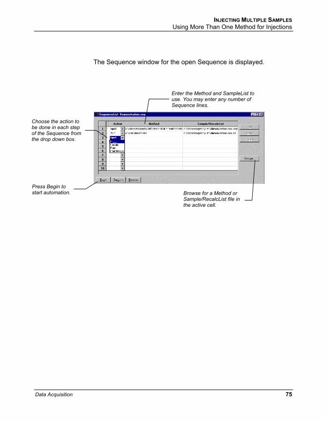
The Sequence window for the open Sequence is displayed.
Enter the Method and SampleList to use. You may enter any number of Sequence lines.
Choose the action to be done in each step of the Sequence from the drop down box.
Press Begin to start automation. Browse for a Method or
Sample/RecalcList file in the active cell.
Data Acquisition 75

76 03-914729-00:4

Automation File Editor
The Automation File Editor is used for editing and creation of automation files, SampleLists, RecalcLists, and Sequences offline (outside of Star Workstation’s System Control application). The Automation File Editor allows access to these files without disrupting automated runs that may be occurring in System Control.
Accessing the Automation File Editor
Click on the Automation File Editor icon on the Star Toolbar.
Data Acquisition 77
Editing or creating a RecalcList
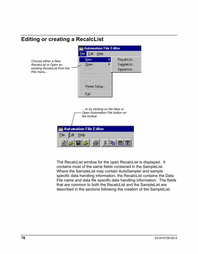
Choose either a New RecalcList or Open an existing RecalcList from the File menu...
…or by clicking on the New or Open Automation File button on the toolbar.
The RecalcList window for the open RecalcList is displayed. It contains most of the same fields contained in the SampleList. Where the SampleList may contain AutoSampler and sample specific data handling information, the RecalcList contains the Data File name and data file specific data handling information. The fields that are common to both the RecalcList and the SampleList are described in the sections following the creation of the SampleList.
78 03-914729-00:4

AUTOMATION FILE EDITOR Editing or creating a RecalcList
As the table is scrolled to reveal additional columns, the Data File and Sample Name column do not scroll. They remain visible so that you can see for which data file and sample you are entering parameters.
Enter postcalculation operations to be performed.
Spreadsheet columns can be sized by dragging their border using the left mouse button. Right-click on column headers for formatting options.
Enter notes about the recalculation of the Data File.
Provides quick access to the Standard Report for viewing the results.
Click here to enter extended data handling parameters.
Data Acquisition 79

Editing or creating a SampleList
Choose either a New SampleList or Open an existing SampleList from the File menu...
…or by clicking on the New or Open Automation File button on the toolbar.
After choosing the SampleList to open the “Select SampleList Section Type” dialog box is displayed. This dialog box allows you to choose a SampleList that is appropriate for the AutoSampler that will be used. The Star Data Acquisition Workstation does not include AutoSampler control, therefore Generic is the only available choice.
80 03-914729-00:4

AUTOMATION FILE EDITOR Editing or creating a SampleList
The SampleList window for the open SampleList is displayed.
Spreadsheet columns can be sized by dragging their border using the left mouse button. Right-click on column headers for formatting options.
Enter notes about the sample.
Enter post run operations to be performed.
As the table is scrolled to reveal additional columns, the Sample Name column does not scroll. It remains visible so that you can see for which sample you are entering parameters.
Enter information about the samples you plan to inject.
Select the location and name for the Data Files generated by the SampleList.
When the table is scrolled to the right, the Sample Name column doesn't scroll so you can easily tell for which sample you are entering additional parameters. Commonly used data handling parameters, the amount for single internal standard calculations, the unidentified peak factor, a multiplier, and a divisor, can be entered directly into this table.
If you have more complex requirements, such as multiple internal standards or multiple detectors requiring different entries for these data handling parameters, click on the button in MultiChannel MultiStandard column.
Data Acquisition 81
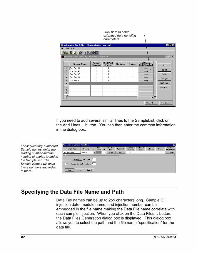
Click here to enter extended data handling parameters.
If you need to add several similar lines to the SampleList, click on the Add Lines… button. You can then enter the common information in the dialog box.
For sequentially numbered Sample names, enter the starting number and the number of entries to add to the SampleList. The Sample Names will have these numbers appended to them.
Specifying the Data File Name and Path Data File names can be up to 255 characters long. Sample ID, injection date, module name, and injection number can be embedded in the file name making the Data File name correlate with each sample injection. When you click on the Data Files… button, the Data Files Generation dialog box is displayed. This dialog box allows you to select the path and the file name “specification” for the data file.
82 03-914729-00:4

AUTOMATION FILE EDITOR Specifying the Data File Name and Path
The left side of the Data File Generation dialog box allows you to select the drive letter and subdirectory (path) where the data files are to be stored. The default directory is the data subdirectory of your Star directory.
The right side of this dialog box allows you to create a file name “specification”. You can combine text entry with the “%” variable symbols shown to specify file names that contain sample injection specific information. An example of the file name is dynamically updated as you type in the file name specification. This makes it easy to see how a Data File created with this file name specifications would appear.
Data Acquisition 83
Specifying Per-Sample Data Handling Parameters Most Data Handling parameters are specified in the Method used during the injection. Some parameters may vary on a per-sample basis, and are therefore specified when you perform the injection. The following Data Handling parameters can be specified on a per-sample basis:
Unidentified Peak Factor
Multiplier
Divisor
Amount Standard when one Internal Standard is being used
Refer to the Data Handling and Reports Operation Manual for a brief description of these parameters.
Refer to the Regulatory Compliance Manual for a complete description of how these parameters are used to calculate results.
Not only can you specify these parameters on a per-sample basis, but you can specify them on a per-detector channel basis. This is useful if, for example, you have an ADC Board with channel A and channel B connected to two different detectors on a GC. In addition, if you are using multiple internal standards, you can also specify their amounts on a per sample and per detector channel basis.
To access these extended Data Handling parameters, click on the button in the Multi-Channel Multi-Standard column in the Inject Single Sample dialog box. You will be prompted for the Method that will be used when this SampleList is run. Then Data Handling Channels dialog box is displayed. When you select the detector channel in the Data Handling Channels dialog box, the calculation type, internal standard peaks and amounts are read from the Method that you just selected. The values entered for internal standard peaks and amounts will be entered into the peak table of this method.
84 03-914729-00:4

AUTOMATION FILE EDITOR Specifying a RecalcList
An amount may be entered for each internal standard peak in the Method.
Select specific detector channels here (up to 4).
Use these buttons to edit the corresponding sections of the active Method.
Specifying a RecalcList From the SampleList RecalcList… button, you can choose to create a new RecalcList, append to an existing RecalcList, or not create nor update a RecalcList. Clicking on the RecalcList button displays the RecalcList Generation dialog box.
If you choose to create a new RecalcList, this automatically generated RecalcList will not overwrite an existing RecalcList unless you also specify “Overwrite the Recalc List each time the SampleList begins”. If a RecalcList with the same file name exists, the newly created RecalcList will have number appended to its file name to make it unique and to prevent the older RecalcList from being overwritten.
Data Acquisition 85

Changing Default SampleList Entries When you add a new row into a SampleList, default values are used for each cell. To change the default values, click on the Defaults… button in the open SampleList window. The following dialog box will be displayed. Enter the desired default values and click on Save.
Using More Than One Method for Injections The Star Workstation allows you to perform automated injections using more than one Method. There are two ways in which this can be accomplished. The first is by changing the active Method from within the SampleList. The second is by using a Sequence.
You may change the Method used during injections by activating a Method in a SampleList row.
Select Activate Method from the Sample Type cell.
Click on the AutoLink button. The Activate Method dialog box is displayed.
86 03-914729-00:4

AUTOMATION FILE EDITOR Using More Than One Method for Injections
Enter the name of the Method to use…
…or pick the Method from a list of files.
When this line is encountered during automated injections, the specified Method is activated.
You may specify any number of Methods to be used in the SampleList.
Data Acquisition 87

88 03-914729-00:4
Editing or creating a Sequence
Choose either a New Sequence or Open an existing Sequence from the File menu...
…or by clicking on the New or Open Automation File button on the toolbar.
The Sequence window for the open Sequence is displayed.
Enter the Method and SampleList to use. You may enter any number of Sequence lines.
Browse for a Method or SampleList file in the active cell.
Choose the action to be done in that step of the Sequence fromthe drop down box.