Dash 2000 Patient Monitor - ardusmedical.com
272
Dash 2000 Patient Monitor Software Version 3 Operator's Manual 2005873-001 ENG Revision C
Transcript of Dash 2000 Patient Monitor - ardusmedical.com

Dash 2000 Patient Monitor Software Version 3
Operator's Manual 2005873-001 ENG Revision C
Kevin
Typewritten Text
www.ardusmedical.com

T-2 Dash 2000 Patient Monitor Revision C 2005873-001
Trademarks
NOTE: The information in this manual only applies to Dash 2000 software version 3.
Due to continuing product innovation, specifications in this manual are subject to change without notice.
Trademarked names appear throughout this document. Rather than list the names and entities that own the trademarks or insert a trademark symbol with each mention of the trademarked name, the publisher states that it is using the names only for editorial purposes and to the benefit of the trademark owner with no intention of improperly using the trademark. 900 SC, ACCUSKETCH, AccuVision, APEX , AQUA-KNOT, ARCHIVIST, Autoseq, BABY MAC, C Qwik Connect, CardioServ, CardioSmart, CardioSys, CardioWindow, CASE, CD TELEMETRY, CENTRA, CHART GUARD, CINE 35, COROLAN, CORO, COROMETRICS, Corometrics Sensor Tip, CRG PLUS, DASH, Digistore, Digital DATAQ, E for M, EAGLE, Event-Link, FMS 101B, FMS 111, HELLIGE, IMAGE STORE, INTELLIMOTION, IQA, LASER SXP, MAC, MAC-LAB, MACTRODE, MARQUETTE, MARQUETTE MAC, MARQUETTE MEDICAL SYSTEMS, MARQUETTE UNITY NETWORK, MARS, MAX, MEDITEL, MEI, MEI in the circle logo, MEMOPORT, MEMOPORT C, MINISTORE, MINNOWS, Monarch 8000, MULTI-LINK, MULTISCRIPTOR, MUSE, MUSE CV, Neo-Trak, NEUROSCRIPT, OnlineABG, OXYMONITOR, Pres-R-Cuff, PRESSURE-SCRIBE, QMI, QS, Quantitative Medicine, Quantitative Sentinel, RAC, RAMS, RSVP, SAM, SEER, SILVERTRACE, SOLAR, SOLARVIEW, Spectra 400, Spectra-Overview, Spectra-Tel, ST GUARD, TRAM, TRAM-NET, TRAM-RAC, TRAMSCOPE, TRIM KNOB, Trimline, UNION, STATION, UNITY logo, UNITY NETWORK, Vari-X, Vari-X Cardiomatic, VariCath, VARIDEX, VAS, and Vision Care Filter are trademarks of GE Medical Systems Information Technologies, Inc., registered in the United States Patent and Trademark Office.
12SL, 15SL, Access, AccuSpeak, ADVANTAGE, BAM, BODYTRODE, Cardiomatic, CardioSpeak, CD TELEMETRY®-LAN, CENTRALSCOPE, Corolation, Dash Port Docking Station, Dash Responder, EK-Pro, EDIC, Event-Link Cumulus, Event-Link Cirrus, Event-Link Nimbus, HI-RES, ICMMS, IMAGE VAULT, IMPACT.wf, INTER-LEAD, LIFEWATCH, Managed Use, MARQUETTE PRISM, MARQUETTE® RESPONDER, MENTOR, MicroSmart, MMS, MRT, MUSE CardioWindow, NST PRO, NAUTILUS, OCTANET, O2 SENSOR, OMRS, PHi-Res, Premium, Prism, QUIK CONNECT V. QUICK CONNECT, QT Guard, SMARTLOOK, SMART-PAC, Spiral Lok, Sweetheart, UNITY, Universal, Waterfall, and Walkmom are trademarks of GE Medical Systems Information Technologies, Inc.
© GE Medical Systems Information Technologies, Inc., 2004. All rights reserved.

Revision C Dash 2000 Patient Monitor NOTICES-1 2005873-001
CE Marking Information
Compliance
The Dash 2000 patient monitor bears CE mark CE-0459 indicating its conformity with the provisions of the Council Directive 93/42/EEC concerning medical devices, and fulfills the essential requirements of Annex I of this directive. The radio-interference emitted by this device is within the limits specified in EN 55011, for class B equipment.
The product complies with the requirements of standard EN 60601-1-2 ”Electromagnetic Compatibility – Medical Electrical Equipment”.
The safety and effectiveness of this device has been verified against previously distributed devices. Although all standards applicable to presently marketed devices may not be appropriate for prior devices (i.e. electromagnetic compatibility standards), this device will not impair the safe and effective use of those previously distributed devices. See user’s information.

NOTICES-2 Dash 2000 Patient Monitor Revision C 2005873-001
General Information
• This manual is an integral part of the product and describes its intended use. It should always be kept close to the equipment. Observance of the manual is a prerequisite for proper product performance and correct operation and ensures patient and operator safety.
• The symbol means ATTENTION: Consult accompanying documents.
• Information which refers only to certain versions of the product is accompanied by the model number(s) of the product(s) concerned. The model number is given on the nameplate of the product.
• The warranty does not cover damages resulting from the use of accessories and consumables from other manufacturers.
• GE Medical Systems Information Technologies is responsible for the effects on safety, reliability, and performance of the product, only if
− assembly operations, extensions, readjustments, modifications, or repairs are carried out by persons authorized by GE Medical Systems Information Technologies
− the electrical installation of the relevant room complies with the requirements of the appropriate regulations; and,
− the device is used in accordance with the instructions for use.
• All publications are in conformity with the product specifications and IEC publications on safety of electromedical equipment as well as with UL and CSA requirements and AHA recommendations valid at the time of printing.
• The GE Medical Systems Information Technologies quality management system complies with the international standards DIN/EN/ISO 9001 and EN 46001, and the Council Directive on Medical Devices 93/42/EEC.

Revision C Dash 2000 Patient Monitor i 2005873-001
Table of Contents
About This Manual ............................................................................ ix Manual Purpose ............................................................................ ix Intended Audience ........................................................................ ix Intended Use ................................................................................. ix Product References ....................................................................... ix Conventions................................................................................... ix
Revision History.................................................................................. x
How to Reach Us................................................................................ xi Service Calls and Product Support.............................................. xi Ordering Supplies & Service Parts.............................................. xi Other Questions or Problems...................................................... xii
Monitor Defaults Worksheet...........................................................xiii
THE BASICS...............................................................1-1
Components......................................................................................1-2 The Monitoring System..............................................................1-2 Dash 2000 Monitor .....................................................................1-2 Optional Nurse Call....................................................................1-3 Optional Centralscope Central Station.....................................1-4 Optional Clinical Information Center .......................................1-5 Optional Laser Printer ...............................................................1-6 Optional Defibrillator and Pacer ...............................................1-7 Optional Dash Port Docking Station.........................................1-8
Operation..........................................................................................1-9 General ........................................................................................1-9 Trim Knob Control....................................................................1-10 Control Keys..............................................................................1-11
Power ....................................................................................1-11 Graph Go/Stop .....................................................................1-11 NBP Go/Stop ........................................................................1-12 Function ...............................................................................1-12 Silence Alarm.......................................................................1-12
Turning Power On .........................................................................1-13 AC Power...................................................................................1-13
Normal Mode........................................................................1-13 Standby Mode ......................................................................1-13
Battery Power ................................................................................1-14 Power Indicator Lights.............................................................1-15 Battery Conditioning................................................................1-16 Battery.......................................................................................1-17
Battery Capacity Gauge......................................................1-17 Battery Service Information Window......................................1-18
Battery Status Messages.....................................................1-18
Software Features..........................................................................1-19
1

ii Dash 2000 Patient Monitor Revision C 2005873-001
Menus.........................................................................1-19 Menu Timeout......................................................................1-19 Main Menu...........................................................................1-19 Parameter Menus ................................................................1-20 More Menus .........................................................................1-20
Popup Menus.............................................................................1-21 Scrolling Popup....................................................................1-21 Pointer Popup ......................................................................1-21 Numeric Popup ....................................................................1-22
Subordinate Menus...................................................................1-22 Direct Action Menu Options ....................................................1-23 Parameter Windows .................................................................1-24 Information Windows ...............................................................1-25 Trim Knob Control Operation When Setting Alarm Limits ..1-26
Graphing (Printing) .......................................................................1-27 Devices.......................................................................................1-27 Manual Graphs .........................................................................1-27
Exclusive Graph Control .....................................................1-27 Alarm Graphs ......................................................................1-27
Pressure Scales .........................................................................1-28 Graphing Messages ..................................................................1-28 Graph Header ...........................................................................1-28
Putting the Monitor Into Operation .............................................1-29 Monitor Installation and Connection ......................................1-29 Performance Check...................................................................1-30
SAFETY.......................................................................2-1
For Your Safety ................................................................................2-2 Intended Use ...............................................................................2-2 Terminology ................................................................................2-2 Monitor Safety ............................................................................2-2 Dangers........................................................................................2-2 Warnings .....................................................................................2-3 Cautions ......................................................................................2-7 Notes ..........................................................................................2-10
Reference Literature......................................................................2-10
Classifications ................................................................................2-11 Underwriters Laboratories, Inc ...............................................2-11 Safe Operating and Handling Conditions...............................2-12 Equipment Symbols..................................................................2-13
ADMIT DISCHARGE .................................................3-1
About Admitting ..............................................................................3-2 You Must Admit to Activate Alarms .........................................3-2 Monitors are Used in Different Ways........................................3-2
Guidelines When Doing Combination Monitoring ..............3-3 For Which Application is the Monitor Set?...............................3-3
Getting to the Admit Menu .............................................................3-4
2
3

Revision C Dash 2000 Patient Monitor iii 2005873-001
Standard Admit Menu.....................................................................3-5
Rover Admit Menu...........................................................................3-6
Combo Admit Menu .........................................................................3-7
Rover Combo Admit Menu ..............................................................3-8
Admit Menu Options .......................................................................3-9 Admit Info ...................................................................................3-9
Change Admit Info ..............................................................3-10 Request Admit Info..............................................................3-11 Save Admit Info ...................................................................3-11 Weight and Height ..............................................................3-11 Age ....................................................................................3-11
Admit Patient............................................................................3-12 Admit Patient.......................................................................3-12 New Case..............................................................................3-12
Set Unit Name ..........................................................................3-13 Set Bed Number........................................................................3-14 Set Graph Location...................................................................3-15 ECG Source ...............................................................................3-15
About Discharging .........................................................................3-16 Discharge Patient .....................................................................3-16
Standard and Rover Admit Menu ......................................3-16 Combo and Rover Combo ....................................................3-17 New Case..............................................................................3-17
ALARM CONTROL.....................................................4-1
Smart Alarms...................................................................................4-2
Alarm Structure ...............................................................................4-3 Patient Status Alarms................................................................4-3 System Status Alarms................................................................4-4
Controlling Audio Alarms ...............................................................4-5 Silencing an Alarm for One Minute ..........................................4-5 Pausing Alarms...........................................................................4-5 Turning Alarm Volume Off Permanently .................................4-5
Alarm Control Menu........................................................................4-6 All Limits.....................................................................................4-7
Viewing an All Limits Screen ...............................................4-7 Changing a Limit in the All Limits Screen..........................4-8
Alarm Graph ...............................................................................4-9 Alarm Volume ...........................................................................4-10 Parameter Alarm Level ............................................................4-11 Arrhythmia Alarm Level..........................................................4-12
MONITOR SETUP......................................................5-1
Monitor Setup Menu........................................................................5-2 Monitor Defaults.........................................................................5-3 Monitor Defaults Menu ..............................................................5-3
4
5

iv Dash 2000 Patient Monitor Revision C 2005873-001
Setup Default Arrhythmia Alarm Levels ..................5-4 Setup Default Parameter Alarm Levels...............................5-6 Setup Default Limits .............................................................5-7 Setup Default Display ...........................................................5-8 Setup Default Parameter Priority ........................................5-9 Recall Default ......................................................................5-10
Display Setup Menu .................................................................5-11 Waveform On / Off ...............................................................5-12 Contrast................................................................................5-13 Color ....................................................................................5-14 Backgrnd ..............................................................................5-14 Time and Date .....................................................................5-14 Set Date................................................................................5-15 Set Time ...............................................................................5-15
Graph Setup ..............................................................................5-16 ECG 1, Waveform 2, Waveform 3.......................................5-17 Graph Location ....................................................................5-18 Alarm Graph ........................................................................5-20 Speed ....................................................................................5-20 Timed Graph ........................................................................5-21
Parameters On / Off..................................................................5-22 Software Summary ...................................................................5-23 Service Mode .............................................................................5-24
Patient Monitor Type ..........................................................5-25 Admit Mode..........................................................................5-25
PATIENT DATA..........................................................6-1
Patient Data Menu ..........................................................................6-2 Vital Signs ...................................................................................6-3
View Older / View Newer ......................................................6-4 Time Interval .........................................................................6-4 Specific Time ..........................................................................6-4 Page Down and Page Up .......................................................6-4
Graphic Trends ...........................................................................6-5 Select Parameters..................................................................6-6 View Older / View Newer ......................................................6-7 Time Period ............................................................................6-7
MAINTENANCE.........................................................7-1
Biocompatibility ...............................................................................7-2
Inspection .........................................................................................7-3
General Cleaning .............................................................................7-4 Exterior Surface ...............................................................................7-4
Display.........................................................................................7-5
Cleaning Applied Parts ...................................................................7-6 Cables and Leadwires.................................................................7-6 Other............................................................................................7-6
Technical Maintenance....................................................................7-7
6
7

Revision C Dash 2000 Patient Monitor v 2005873-001
Technical Inspections ............................................................7-7
Changing Graph Paper....................................................................7-8 Built-in Writer .......................................................................7-8
Thermal Paper Storage ...................................................................7-9
ECG .............................................................................8-1 Introduction......................................................................................8-2
Checklist......................................................................................8-2 Skin Preparation..............................................................................8-3 Electrode Placement ........................................................................8-4
5-Leadwire Electrode Placement ...............................................8-4 3-Leadwire Electrode Placement ...............................................8-5
Three-leadwire Configuration ..............................................8-5 Electrode Placement for Neonates.............................................8-6 Electrode Placement for Pacemaker Patients ..........................8-7 Maintaining Quality ECG Signal ..............................................8-8 Surgical Considerations for Electrode Placement (Adults) .....8-8
ESU ECG Filters..............................................................................8-8 Electrosurgical Unit (ESU Cable) .............................................8-8
ECG Monitoring Features...............................................................8-9 ECG Display................................................................................8-9 Getting to the ECG Menu ........................................................8-10
ECG Menu Options........................................................................8-11 Display Lead .............................................................................8-11
Synchronized Cardioversion ...............................................8-11 Smart-Lead Fail...................................................................8-12 Leads Fail Patient Condition..............................................8-12
ECG Size....................................................................................8-13 ECG Limits................................................................................8-14
Heart Rate............................................................................8-14 Relearn ......................................................................................8-15 QRS Volume ..............................................................................8-15 Analysis Settings ......................................................................8-16
ECG Filter............................................................................8-17 Lead Analysis.......................................................................8-18 Multi-Lead Analysis ............................................................8-18 Single Lead Analysis ...........................................................8-18 Changing Lead Analysis .....................................................8-18 Detect Pace...........................................................................8-19 Safety Considerations .........................................................8-19 Monitoring Internal Pacemaker Patients ..........................8-20 Monitoring Dash Responder Paced Patients .....................8-21 QRS Width ...........................................................................8-22 Changing QRS Width ..........................................................8-22 Arrhythmia ..........................................................................8-23 Lethal ...................................................................................8-23 Arrhythmia Conditions .......................................................8-23
Troubleshooting .............................................................................8-25
Internal Pacemaker Troubleshooting...........................................8-26
8

vi Dash 2000 Patient Monitor Revision C 2005873-001
PRESSURES ...............................................................9-1
Introduction......................................................................................9-2 Assigned BP Names....................................................................9-3
Zero Reference..................................................................................9-4
Checklist ...........................................................................................9-4
Pressure Monitoring Features ........................................................9-5 Pressure Information..................................................................9-5 Getting to the Pressure Menu....................................................9-6
Pressure Menu Options ...................................................................9-7 Scales ...........................................................................................9-7 Cursor ..........................................................................................9-8 Clear Cursor................................................................................9-8 Limits...........................................................................................9-9 Change Name............................................................................9-10 Zero ............................................................................................9-10 Settings......................................................................................9-11
BP Filter...............................................................................9-12 Calibrate Transducer ..........................................................9-12 Smart BP..............................................................................9-13 Pulse Rate ............................................................................9-13 Disconnect Alarm.................................................................9-14
Troubleshooting .............................................................................9-15
NBP ...........................................................................10-1
Introduction....................................................................................10-2 Checklist....................................................................................10-5
Patient Preparation .......................................................................10-6
NBP Monitoring Features .............................................................10-7 NBP Information ......................................................................10-7
Mean Arterial Pressure.......................................................10-7 Systolic Search.....................................................................10-8 NBP Go/Stop Key.................................................................10-8 Power Key ............................................................................10-8
Getting to the NBP Menu ........................................................10-9
NBP Menu Options......................................................................10-10 NBP Auto.................................................................................10-10 NBP Stat..................................................................................10-11
Early Systolic Measurement.............................................10-11 NBP Limits..............................................................................10-12 NBP Settings...........................................................................10-13
Cuff Size .............................................................................10-14 Initial Cuff Pressure..........................................................10-14
Review NBPs...........................................................................10-15 Clear NBP Reading.................................................................10-15
Troubleshooting ...........................................................................10-16 NBP Status Messages.............................................................10-16
10
9

Revision C Dash 2000 Patient Monitor vii 2005873-001
SPO2..........................................................................11-1
Introduction....................................................................................11-2
Neonates and Infants ....................................................................11-3
Checklist .........................................................................................11-4
Patient Preparation .......................................................................11-5
Signal and Data Validity...............................................................11-6 Signal Strength Indicator.........................................................11-6 Quality of SPO2 Waveform ......................................................11-6 Stability of SPO2 Values ..........................................................11-7
SPO2 Monitoring Features ...........................................................11-8 SPO2 Information.....................................................................11-8 Getting to the SPO2 Menu.......................................................11-9
SPO2 Menu Options ....................................................................11-10 Size...........................................................................................11-10 SPO2 Limits ............................................................................11-11 Rate Volume............................................................................11-12 Rate..........................................................................................11-12
Probe Off Patient Condition........................................................11-13
Troubleshooting ...........................................................................11-14 SPO2 Messages .......................................................................11-14
RESPIRATION..........................................................12-1
Introduction....................................................................................12-2 General Information .................................................................12-3 Checklist....................................................................................12-4
Respiration Monitoring Features .................................................12-5 Respiration Information...........................................................12-5 Getting to the Respiration Menu.............................................12-6
Respiration Menu Options ............................................................12-7 Lead ...........................................................................................12-7 Relearn Respiration..................................................................12-7 Respiration Limits ....................................................................12-8 Sensitiv ......................................................................................12-9 Cardiac Artifact Alarm...........................................................12-10 Size...........................................................................................12-11
Auto Size ............................................................................12-11 Manual Size .......................................................................12-11
Troubleshooting ...........................................................................12-12 Respiratory Waveform............................................................12-12
Cardiac Artifact .................................................................12-12 Varying Amplitudes...........................................................12-13
Messages..................................................................................12-13
12
11

viii Dash 2000 Patient Monitor Revision C 2005873-001
TEMPERATURE.......................................................13-1
Introduction....................................................................................13-2 Checklist....................................................................................13-2
Temperature Monitoring Features...............................................13-3 Temperature Information ........................................................13-3 Getting to the Temperature Menu ..........................................13-4
Temperature Menu Options..........................................................13-5 Units ..........................................................................................13-5 TP Limits...................................................................................13-5
Troubleshooting .............................................................................13-6 Messages....................................................................................13-6
APPENDICES ...........................................................14-1
Defib Sync/Analog Output.............................................................14-2 ECG Acquisition Modules ........................................................14-2
Abbreviations and Symbols...........................................................14-3 Abbreviations ............................................................................14-3 Symbols......................................................................................14-9
Software Packages .......................................................................14-10
Factory Defaults—Adult-ICU Mode ...........................................14-11
Factory Defaults—Neonatal-ICU Mode .....................................14-15
Factory Defaults—Operating Room Mode .................................14-19
Minimum and Maximum Limits (Default Mode) ......................14-23
Technical Specifications ..............................................................14-24 Display.....................................................................................14-24 Controls ...................................................................................14-24 Processing................................................................................14-24 Alarms .....................................................................................14-25 ECG..........................................................................................14-25 Respiration ..............................................................................14-26 Temperature (TEMP) .............................................................14-27 Invasive Blood Pressure (BP).................................................14-27 Pulse Oximetry (SpO2)...........................................................14-28 Non-invasive Blood Pressure (NBP)......................................14-28 Paper Recorder........................................................................14-30 Analog Output.........................................................................14-30 Defibrillator Synchronization Pulse ......................................14-30 Environmental Specifications ................................................14-31 Physical Specifications ...........................................................14-32 Certification ............................................................................14-32 Warranty .................................................................................14-32
14
13

Revision C Dash 2000 Patient Monitor ix 2005873-001
About This Manual
Manual Purpose Intended Audience Intended Use Product References Conventions
This manual contains the instructions to operate the Dash 2000 patient monitor safely and in accordance with its functions and intended use.
This manual is geared for clinical professionals. Clinical professionals are expected to have working knowledge of medical procedures, practices, and terminology as required for monitoring of critically ill patients.
This product is intended for use as a hospital patient monitor. It is NOT intended for home use.
The Dash 2000 patient monitor is referred to in this manual as the Dash monitor or simply the monitor.
The Centralscope central station and the Clinical Information Center are generically referred to as the central station in this manual.
The PRN 50 and the Direct Digital Writer (DDW) are referred to as writer.
The laser printer is referred to as the printer.
References to screen text appear throughout this manual in all capital letters (for example ECG, DISCHARGED, SAVING, ALARM VOLUME OFF, etc.). This manual refers to keys, menus, and menu options.
Keys—a labeled button found on the front of the monitor which you press to activate.
Menus and Menu Options—A menu is text which appears at the bottom of the display screen. A menu is composed of a set of menu options. Each menu option is enclosed in a rectangle.
How can you tell what software package you have? Follow this procedure:
1. Select MORE MENUS option from the Main Menu.
2. Select MONITOR SETUP from the menu displayed.
3. Select SOFTWARE SUMMARY from the Monitor Setup Menu. An information window is displayed. The software package number is displayed in the second line of the title in the information window.
Illustrations
All illustrations in this manual are provided as examples only. They may not necessarily reflect your monitoring setup or data displayed on your monitor.

x Dash 2000 Patient Monitor Revision C 2005873-001
Revision History
This manual has a revision letter, located at the bottom of each page. This revision letter changes whenever the manual is updated.
Revision Date Comments
A April 2001 This document corresponds with the Dash monitor software version 3.
B April 2002 ECO 070505
C September 2002 ECO 072030
C1 February 2004 ECO 075999 Updated addresses

Revision C Dash 2000 Patient Monitor xi 2005873-001
How to Reach Us
Service Calls and Product Support Ordering Supplies & Service Parts
To open a service call or obtain product support call the numbers below:
800.558.7044 (US & Canada) 561.575.5000 (outside US)
or contact your representative or distributor
For other product information please contact one of the offices listed on the next page.
Order supplies (leadwires, electrode paste, thermal paper, etc.) or service parts (manuals, circuit boards, cables, software, etc.) from:
Accessories GE Medical Systems Accessories and Supplies 2607 North Grandview Blvd. Mail Code: SN-471 Waukesha, WI 53188 Telephone: 800.558.5102 (US only) 262.521.6856 (outside US) Fax: 800.232.2599 (US only) 262.521.6855 (outside US)
Service parts GE Clinical Services P.O. Box 9100, 100 Marquette Drive Jupiter, FL 33468-9100 Telephone: 800.558.7044 (US only) 561.575.5000 (outside US) Fax: 800.421.6841 (US only) 561.575.5050 (outside US)
Have the following information available before calling:
• part number of the defective part, or
• model and serial number of the equipment,
• part number/name of the assembly where the item is used,
• item name, and
• where applicable, reference designation (e.g., R13, S12, U32).
Ordering Manuals When ordering additional operator manuals, be sure to include the software version of the product.

xii Dash 2000 Patient Monitor Revision C 2005873-001
Other Questions or Problems
For additional information contact one of the offices listed below or see our website at www.gemedicalsystems.com.
Headquarters World Headquarters GE Medical Systems Information Technologies, Inc. 8200 West Tower Avenue Milwaukee, WI 53223 USA Tel: + 1 414 355 5000 1 800 558 5120 (US only) Fax: + 1 414 355 3790
Europe GE Medical Systems Information Technologies GmbH Munzinger Straße 3-5 D-79111 Freiburg Germany Tel: + 49 761 45 43 - 0 Fax: + 49 761 45 43 - 233
Asia Headquarters GE Medical Systems Information Technologies Asia; GE (China) Co., Ltd. 24th Floor, Shanghai MAXDO Center, 8 Xing Yi Road, Hong Qiao Development Zone Shanghai 200336, P.R. China Tel: + 86 21 5257 4650 Fax: + 86 21 5208 2008

Revision C Dash 2000 Patient Monitor xiii 2005873-001
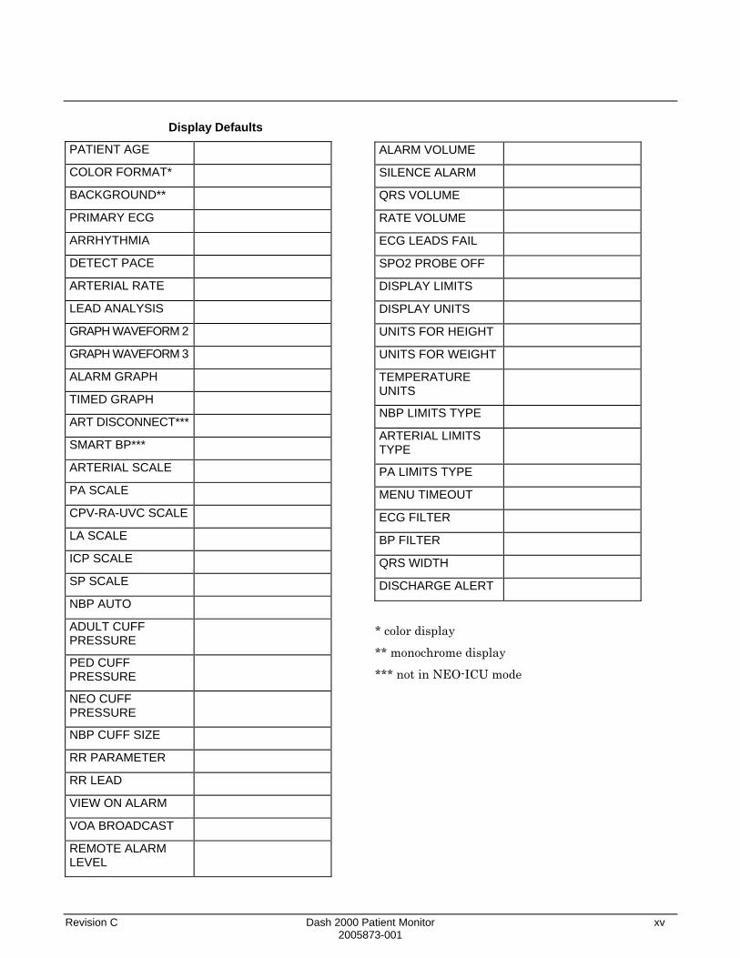
Monitor Defaults Worksheet
You can customize alarm limits and levels as well as numerous display options. Your settings can be set up as Monitor Defaults to be recalled with each discharge procedure. Refer to the Monitor Setup chapter of this manual for details.
We have provided this worksheet as an optional reference tool. Fill it out and keep it in a prominent place to refer to your setup. You may want to make additional copies of the worksheet for future use before filling it out.
Arrhythmia Alarm Levels Crisis Warning Advisory Message
Asystole VFib/VTac VTach Brady (NEO mode)
Date: ________________ Unit: ______________
Patient Monitor Type (circle one):
ADULT ICU NEONATAL-ICU OPERATING ROOM
NOTE: Changing patient-monitor type after setup erases your monitor defaults and reinstates monitor defaults.
Parameter Alarm Levels Crisis Warning Advisory Message
HR ART PA CVP NBP SPO2 FEM UAC RA UVC LA ICP SP ART Rate SPO2 Rate FEM Rate UAC Rate RR Resp Apnea TP

xiv Dash 2000 Patient Monitor Revision C 2005873-001
Parameter Limits Low High
HR
NBP-S
NBP-D
NBP-M
ART-S
ART-D
ART-M
ART-R
FEM-S
FEM-D
FEM-M
FEM-R
UAC-S
UAC-D
UAC-M
UAC-R
PA-S
PA-D
PA-M
CVP
RA
UVC
LA
ICP
SP
SpO2
SpO2-R
RR
RR-Apnea
TP
Revision C Dash 2000 Patient Monitor xv 2005873-001
Display Defaults
PATIENT AGE
COLOR FORMAT*
BACKGROUND**
PRIMARY ECG
ARRHYTHMIA
DETECT PACE
ARTERIAL RATE
LEAD ANALYSIS
GRAPH WAVEFORM 2
GRAPH WAVEFORM 3
ALARM GRAPH
TIMED GRAPH
ART DISCONNECT***
SMART BP***
ARTERIAL SCALE
PA SCALE
CPV-RA-UVC SCALE
LA SCALE
ICP SCALE
SP SCALE
NBP AUTO
ADULT CUFF PRESSURE
PED CUFF PRESSURE
NEO CUFF PRESSURE
NBP CUFF SIZE
RR PARAMETER
RR LEAD
VIEW ON ALARM
VOA BROADCAST
REMOTE ALARM LEVEL
ALARM VOLUME
SILENCE ALARM
QRS VOLUME
RATE VOLUME
ECG LEADS FAIL
SPO2 PROBE OFF
DISPLAY LIMITS
DISPLAY UNITS
UNITS FOR HEIGHT
UNITS FOR WEIGHT
TEMPERATURE UNITS
NBP LIMITS TYPE
ARTERIAL LIMITS TYPE
PA LIMITS TYPE
MENU TIMEOUT
ECG FILTER
BP FILTER
QRS WIDTH
DISCHARGE ALERT
* color display
** monochrome display
*** not in NEO-ICU mode

xvi Dash 2000 Patient Monitor Revision C 2005873-001
Parameter Priority Defaults
Indicate which parameters you want to have priority in the first 3 positions on the display. ECG always appears first and cannot be changed.
Parameter 1 ECG
Parameter 2
Parameter 3
Circle the other parameters you want to have priority after position 3. The software prevents you from selecting more parameters than allowable.
NBP UVC ART LA FEM ICP UAC SP PA SPO2
CVP RR RA TP

Revision C Dash 2000 Patient Monitor 1-1 2005873-001
1 THE BASICS Components......................................................................................1-2
The Monitoring System.............................................................1-2 Dash 2000 Monitor .....................................................................1-2 Optional Nurse Call....................................................................1-3 Optional Centralscope Central Station.....................................1-4 Optional Clinical Information Center .......................................1-5 Optional Laser Printer ..............................................................1-6 Optional Defibrillator and Pacer ...............................................1-7 Optional Dash Port Docking Station.........................................1-8
Operation..........................................................................................1-9 General ........................................................................................1-9 Trim Knob Control....................................................................1-10 Control Keys..............................................................................1-11
Turning Power On .........................................................................1-13 AC Power...................................................................................1-13
Battery Power ................................................................................1-14 Power Indicator Lights.............................................................1-15 Battery Conditioning................................................................1-16 Battery.......................................................................................1-17 Battery Service Information Window......................................1-18
Software Features..........................................................................1-19 Menus ........................................................................................1-19 Popup Menus.............................................................................1-20 Subordinate Menus...................................................................1-22 Direct Action Menu Options ....................................................1-23 Parameter Windows .................................................................1-24 Information Windows ...............................................................1-25 Trim Knob Control Operation When Setting Alarm Limits ..1-26
Graphing (Printing) .......................................................................1-27 Devices.......................................................................................1-27 Manual Graphs .........................................................................1-27 Pressure Scales .........................................................................1-28 Graphing Messages ..................................................................1-28 Graph Header ...........................................................................1-28
Putting the Monitor Into Operation .............................................1-29 Monitor Installation and Connection ......................................1-29 Performance Check...................................................................1-30

1-2 Dash 2000 Patient Monitor Revision C 2005873-001
Components
The Monitoring System
Dash 2000 Monitor
The Dash 2000 patient monitor can function by itself with a built-in writer (optional) or it can be cabled in with the Unity network via Ethernet. Optional components are, if cabled to Ethernet, a Centralscope central station and the Clinical Information Center.
This device is designed to monitor a fixed set of parameters including ECG, noninvasive blood pressure, impedance respiration, SpO2, and temperature. Invasive pressure is an optional feature.
All of the patient cable connectors are located on the right side panel of the monitor. The screen displays patient information in a logical, easily understood format. A Trim Knob control provides single control operation of virtually all monitor functions.
The monitor is available in both monochrome and color.
DASH 2000
AC Battery
Power
Graph Go/Stop
NBP Go/Stop
Function
Silence Alarm
Trim Knob
Charging Status
ECG 150/ 5021-NOV-1998 16:27
II
SPO2
DAK.BED 1
75SPO2 105/ 90
RT70* * * 97NBP 200/ 80
ADT
XX
X/
MOREMENUS
+ -
Patient CableConnectors
Trim KnobControl
Screen
001
Monitor, Front and Side Views
The illustration above shows one invasive pressure connector (labeled BP). This is an optional feature which your monitor may not have. References are made to this optional feature throughout the manual. Please ignore such references if this feature was not purchased with your monitor.

Revision C Dash 2000 Patient Monitor 1-3 2005873-001
On the back of the monitor, you can find all connectors for equipment and network. (See the illustration below.)
NOTE: Refer to the service manual for system safety requirements when connecting the monitor to accessory equipment.
Aux Port – Used for nurse call connector only.
Defib Sync Connector – Provides ECG analog output signals to user-supplied equipment. A 5-volt, 2-milisecond artificial pacer spike is added to the analog output when PACE is on and detection occurs. Refer to the Appendices, Analog Output, for details on signal output.
Network Connector – A cablecan be connected to this portfor monitors used in the patientmonitoring network configuration.
002
Handle – An optional alarm indicator can bebuilt into the handle of the monitor (not shown). When activated, the LED indicator flashes redfor CRISIS and WARNING patient status alarms and yellow for all other alarms.
AC Power Connector
PeripheralExpansionConnector
Monitor, Back View
Optional Nurse Call
For connection of the monitor to a nurse-call system, a separation line according to IEC 60601 (4 kV voltage isolation) is required. Use parts set 2005693-001. Please note the information given in chapter 4, section "Alarm Structure", on the different categories of transferred alarms.

1-4 Dash 2000 Patient Monitor Revision C 2005873-001
Optional Centralscope Central Station
The GE Medical Systems Information Technologies Unity Network (Ethernet) establishes bed-to-bed communication and allows patient data to be sent to an optional Centralscope central station and to other monitors on the network. All devices must be connected to the network.
The central station may have a built-in writer for graphing (printing). This built-in writer uses 2-inch wide graph paper.
012A Centralscope Central Station
The Centralscope Central Station is generically referred to as the central station throughout this manual.
Refer to the Centralscope central station operator’s manual for instructions on operation.

Revision C Dash 2000 Patient Monitor 1-5 2005873-001
Optional Clinical Information Center
The Unity Network (Ethernet) establishes bed-to-bed communication and allows patient data to be sent to an optional Clinical Information Center and to other monitors on the network. All devices must be connected to the network.
Clinical Information Center
The Clinical Information Center is generically referred to as the central station throughout this manual.
Refer to the Clinical Information Center operator's manual for instructions on operation.

1-6 Dash 2000 Patient Monitor Revision C 2005873-001
Optional Laser Printer
An optional laser printer (not shown) connects to the central station. It is identified on the Dash monitor as LASER when choosing a graph location. (Refer to the Monitor Setup chapter for more details.)
When you choose the laser printer as the print window location, it can print any printable information window when it is displayed and the GRAPH GO/STOP key is pressed.
When you choose the laser printer as the manual graph location, it will print the waveforms as selected in Graph Setup when the GRAPH GO/STOP key is pressed. It prints 20 seconds of waveforms per page in a cascade format when the graph speed is set for 25 millimeters per second. There will be a delay of approximately one minute until the first page is printed, then it will run until all patient data is printed.
NOTE: The one-minute delay does not mean the data printed is delayed. It just takes that long for the information to be processed by the laser printer. The amount of data printed will increase and the delay will be longer if a speed slower than 25 mm/s is chosen.
When you choose the laser printer as the alarm graph location, it will provide 20 seconds of waveforms per page in a cascade format, but again, there will be a delay of one minute until the first page is printed.

Revision C Dash 2000 Patient Monitor 1-7 2005873-001
Optional Defibrillator and Pacer
The Dash Responder® defibrillator (with optional integrated pacer) also connects to the Dash 2000 patient monitor, version 3.
AC Battery
Power
Graph Go/Stop
NBP Go/Stop
Function
Silence Alarm
Trim Knob
Charging Status
patient monitor
DASH 2000
1 2 3On/Off Charge Shock
Sync.
Energy Select J(50Ω )Charging Status
Pacer Pause
Pacer Mode
Pacer On/Off
Rate (ppm)
Output (mA)
Dash Respondertranspor t defibr i l lator
139 Dash Responder® defibrillator with Dash 2000 patient monitor
Refer to the Dash Responder Operator's Manual for instructions on operation.
WARNING Arrhythmia processing is suspended during external pacing with the Dash Responder.
Refer to the ECG chapter in this manual for notes on influences of the Dash Responder defibrillator and pacer.
NOTE: Only versions 3 and higher of the Dash 2000 patient monitor are capable of communicating with the Dash Responder.

1-8 Dash 2000 Patient Monitor Revision C 2005873-001
Optional Dash Port Docking Station
Via the Dash Port Docking Station, the Dash 2000 patient monitor, version 3, can also be powered, connected to Ethernet and to the nurse-call system.
Refer to the Dash Port Docking Station Operator's Manual for instructions on operation.
NOTES: The Dash 2000 patient monitor can only be connected either to the Dash Responder or to the Dash Port Docking Station at a time.
Only versions 3 and higher of the Dash 2000 patient monitor are compatible with the Dash Port Docking Station.

Revision C Dash 2000 Patient Monitor 1-9 2005873-001
Operation
General Below is an illustration of the front of the monitor with a waveform display. The parts of the monitor and display which are involved in the operation of the monitor are labeled. Each of these is described in more detail on the following pages.
DASH 2000
AC Battery
Power
Graph Go/Stop
NBP Go/Stop
Function
Silence Alarm
Trim Knob
Charging Status
ECG 150/ 5021-NOV-1998 16:27
II
SPO2
DAK.BED 1
75SPO2 105/ 90
RT70* * * 97NBP 200/ 80
ADT
XX
X/
MOREMENUS
+ -
003
Power
ParameterWindows
GraphGo/Stop
NBPGo/Stop
Function
Trim KnobControl
Silence Alarm
Operating the Dash 2000 Patient Monitor

1-10 Dash 2000 Patient Monitor Revision C 2005873-001
Trim Knob Control
The main operator control is the Trim Knob control. The Trim Knob control rotates in either direction to highlight parameter labels and menu options. After highlighting the desired selection, press the Trim Knob control to view a new menu or a small popup menu. This procedure is referred to as ”select” throughout the manual.
Remember, when using the Trim Knob control, rotate to highlight, then press to select.
AC Battery
Power
Graph Go/Stop
NBP Go/Stop
Function
Silence Alarm
Trim Knob
Charging Status
ECG 150/ 50
75SPO2 105/ 90
RT70* * * 97NBP 200/ 80
ADT
XX
X/
003A Trim Knob Control

Revision C Dash 2000 Patient Monitor 1-11 2005873-001
Control Keys
Power
Graph Go/Stop
On the right side of the monitor are five control keys. Their functions are described below. Press the key to activate the function.
Beginning with the upper key and reading down, the keys are:
AC Battery
Power
Graph Go/Stop
NBP Go/Stop
Function
Silence Alarm
Trim Knob
Charging Status
ECG 150/ 50
75SPO2 105/ 90
RT70* * * 97NBP 200/ 80
ADT
XX
X/
004 Location of Control Keys
The monitor will be powered at all times when plugged into AC power. This key turns the monitoring function ON and OFF. When the monitor is turned off, patient monitoring is discontinued; however, patient data already accumulated is retained and the battery charging function continues.
NOTES: To avoid unintentional switchoff, the POWER key must be pressed at least 0.25 seconds to switch off the monitor.
In the event of a lockup, you can force a switch-off by pressing the POWER key for five seconds.
Press this key once to start a graph run of the patient’s data. Press a second time to stop. If pressed during an alarm graph run, the graph will run continuously until GRAPH GO/STOP is pressed again. Note that an alarm graph run is usually an automatic 20-second timed graph.
This key is also used to print a copy of non-real time screens. We refer to these as information windows. Not all information windows can be printed. If a printable information window is displayed, press GRAPH GO/STOP to print a copy. If a nonprintable information window is displayed, pressing the GRAPH GO/STOP key prints patient data as if the information window was not displayed.

1-12 Dash 2000 Patient Monitor Revision C 2005873-001
NBP Go/Stop
Function
Silence Alarm
This key starts one noninvasive blood pressure measurement. It can also be used at any time to stop a measurement in process.
NOTE: In Operating Room Mode, if an auto mode time is set in monitor defaults, pressing the NBP GO/STOP key starts the auto mode feature.
This key zeroes the invasive pressure line. The pressure can also be zeroed, if desired, with a menu option in the pressure menu. (If your monitor does not have the invasive pressure option, this key will be present, but will not affect the operation of the monitor.)
This key silences a current, audible alarm for 60 seconds. Only new alarms of equal or higher level interrupt the silence command.
WARNING Alarms do not sound, alarm graphs do not print, and alarms are not sent to the central station during an "Alarm Pause" condition.
Press the key twice during an alarm to start an alarm pause (five minutes for Adult-ICU, 3 minutes for Neonatal-ICU). Press the key again during the alarm pause to reactivate alarms.
If no alarm is sounding, press this key to start an alarm pause.
If your monitor is set up for Operating Room mode, you have three levels of alarm pause:
• Press once (if an alarm is sounding you must press twice) to start a 5-minute alarm pause;
• Press again to start a 15-minute alarm pause;
• Press again to start a permanent alarm pause;
• Press again to reactivate alarms.

Revision C Dash 2000 Patient Monitor 1-13 2005873-001
Turning Power On
AC Power
Normal Mode
Standby Mode
The Dash 2000 monitor will be powered at all times when using AC power (there is no AC power switch). The monitor is preset at the factory for a specific AC voltage. Before applying power, be sure the power requirements match your power supply. Refer to the label on the back of the unit for the voltage and current requirements. Refer also to Power Requirements in the Safety chapter of this manual.
When all cables are properly connected, press the POWER button to turn the monitor on. After approximately 10 seconds you should see a display on the screen. The AC indicator on the front panel will light when using AC power.
Two modes of operation are available when using AC power. The monitor will enter "NORMAL" mode when plugged into AC power and the monitor is turned ON. Normal mode operation provides all functional capabilities of the monitor including vital signs monitoring, communications, and battery charging.
The monitor will enter "STANDBY" mode when plugged into AC power and the monitor is turned OFF. The battery charging function is the only function provided when the monitor is off.
AC Battery
Power
Graph Go/Stop
NBP Go/Stop
Function
Silence Alarm
Trim Knob
Charging Status
ECG 150/ 50
75SPO2 105/ 90
RT70* * * 97NBP 200/ 80
ADT
XX
X/
AC power indicator
005 AC Power Indicator

1-14 Dash 2000 Patient Monitor Revision C 2005873-001
Battery Power The monitor has a built-in battery pack to provide power to the monitor whenever AC power is interrupted. The battery pack is composed of ten nickel cadmium batteries. The battery pack is generally referred to as the ”battery.”
You must charge the battery before using it. There is no external charger. The battery is charged when the monitor is connected to AC power. A fully depleted battery will take 1 hour when the monitor is switched off, and up to 3 hours when the monitor is switched on, to fully charge. To assure a fully charged battery which is ready for use, we recommend that the monitor be plugged into AC power whenever it is not in use.
Depending on usage, you can get 2 to 3 hours of battery power on a new, fully-charged battery on a color monitor, and up to 4 hours on a monochrome monitor. NBP and SpO2 monitoring and the usage of the recorder will drain battery power faster than other parameters.
NOTE: A "Battery Low" message at the top of the screen and an audible system alarm indicate 10 minutes of battery life remaining. You should connect the monitor to an AC power source when the message is displayed.
CAUTION The battery discharges even when the device is not operating.
• Please ensure that the battery is always fully charged when you are keeping the device in storage for an extended period of time.
• Check the battery status at least once every month and recharge the battery (see "Environmental Specifications --> Storage Conditions").
• Condition the battery every three months (see "Battery Conditioning" below).

Revision C Dash 2000 Patient Monitor 1-15 2005873-001
Power Indicator Lights
There are three power indicator lights on the front of the monitor. The illustration below identifies these indicator lights.
AC Battery
Power
Graph Go/Stop
NBP Go/Stop
Charging Status
AC Power LED
Battery Power LED
Charging status indicator
007 Power Indicator Lights
These indicators, when lit, denote a power condition. Conditions may be designated with a single indicator or a combination of indicators. The chart below details these power conditions and their indicators.
In the chart below, an "X" indicates that the indicator light shown at the top of the column is lit.
Conditions Indicated by Power Indicator Lights
AC Battery Charging Status
Unit is AC powered; battery is being charged
X yellow X
Unit is AC powered; battery is fully charged
X green X
Unit is battery powered
X
Conditioning; battery is being discharged*
X X
* In this condition, the battery can be used but be aware it is not fully charged so usage time is unpredictable. The system message "COND IS RUNNING" is displayed.
NOTE: If the Charging Status LED is blinking yellow, this indicates a malfunction in the battery management system. Please contact Service.

1-16 Dash 2000 Patient Monitor Revision C 2005873-001
Battery Conditioning To obtain the greatest possible battery performance and to keep the fuel gauge up to date, the battery needs to be conditioned every 3 months or after 250 discharge cycles.
There are three battery conditioning modes: automatic, user-controlled, and manual.
• automatic mode: Conditioning starts automatically when the time limit (3 months) or the discharge limit (250 cycles) is reached. The automatic start time for the conditioning cycle is defined with the softkey AUTO START AT. (Should there be a loss of AC power, all the user has to do is plug in the power cord.)
• user-controlled mode: If the time limit or discharge limit is reached, the monitor displays the status message "BATTERY NEEDS COND". It is up to the user to start the conditioning as a result of this message.
• manual mode: In this mode the user is required to manually start the conditioning process. The time limit or discharge limit is not observed and has no effect. The conditioning process is started from the service menu.
• In the user-controlled and manual modes, conditioning is started using this menu sequence: MONITOR SETUP > SERVICE MODE > BATTERY SERVICE > START CONDITION (notify service!).

Revision C Dash 2000 Patient Monitor 1-17 2005873-001
Battery
Battery Capacity Gauge
The battery capacity gauge or bar graph indicates the battery charge capacity. The gauge is drawn as a vertical, rectangular outline which is filled in from bottom to top proportional with the battery charge level.
The full rated capacity of the type of battery installed will be represented on the gauge by a dashed outline. The maximum charge level for the cell currently installed in the monitor is represented by a solid outline on the gauge. As the battery ages-and its charging capacity becomes diminished-this line becomes a smaller percentage of the full rated capacity shown by the solid line. Refer to the following examples:
New battery,fully charged
New battery,approximately60% charged
Old battery,fully charged
Old battery, chargedto approximately75% of its current
capacity (less thanhalf of its new capacity)
008

1-18 Dash 2000 Patient Monitor Revision C 2005873-001
Battery Service Information Window
Battery Status Messages
The Battery Service Information window can be accessed using the Trim Knob in the Monitor Setup Service Mode menu by selecting the Battery Service softkey. The Battery Service Information window includes the following information:
BATTERY SERVICE INFORMATION
BATTERY CAPACITY NEW ACTUAL FULL ACTUAL REMAINING FULL/NEW REPLACE BELOWBATTERY TEMPERATURE:LAST CONDITIONING:
200019845009940
25.0
21-NOV-1998 16:27
mAhmAhmAh%%˚C
009 Battery Service Information Window
The BATTERY LOW message is displayed in the STATUS MESSAGE line and indicates 10 minutes of battery life remaining. You should connect the monitor to an AC power source when the message is displayed. The REPLACE BATTERY message is displayed in the STATUS MESSAGE line if, when fully charged, the battery reaches only 40% capacity of its design capacity for cell type. The BATTERY NEEDS COND system message is displayed when the battery needs to be reconditioned. The COND IS RUNNING message is displayed while the battery is being reconditioned. The BATTERY DEFECTIVE message is displayed when errors have occurred within the battery management system or the battery. The reason of the error can be found in the error logbook (MONITOR SETUP -> SERVICE MODE -> REVIEW ERRORS -> VIEW OUTPUT ERRORS). Notify Service. Environmental Issues: GE Medical Systems Information Technologies strives to produce products that are both user safe and environmentally friendly. We sincerely believe that our products and the production methods used to produce them, meet these goals.
Battery Notice: This product contains a rechargeable battery. The average life span of this type of battery is approximately three years. When replacement becomes necessary, contact a qualified service representative to perform the replacement.
Disposal Notice: Should this product become damaged beyond repair, or for some reason its useful life is considered to be at an end, please observe all local, state, and federal regulations that relate to the disposal of products that contain lead, batteries, plastics, etc.

Revision C Dash 2000 Patient Monitor 1-19 2005873-001
Software Features
Menus
Menu Timeout
Main Menu
A menu, like the name implies, is a selection of available options. These options are displayed at the bottom of the screen and are accessed with the Trim Knob control. Some menus may have some empty spaces. These spaces are available for future software enhancements.
There are two important menu options to note. One or both of these options is found in every menu with the exception of the Main Menu.
MAIN MENU This option will always take you back to the Main Menu. Use it when you are finished making adjustments or accessing stored information.
PREV MENU This option allows you to back up to the previous menu when a subordinate menu is displayed.
Think of these as escape or exit options.
The monitor automatically returns to the Main Menu (refer to the figure below) when you have displayed another menu and have not used the Trim Knob for 5 minutes (default time). This is a Monitor Defaults setting (SETUP DEFAULT DISPLAY) which can be set for a longer period of time or no timeout at all. Some menus, such as Vital Signs and trends, are not affected by the timeout setting. You must exit them using one of the exit options described above.
The Main Menu has one menu option, MORE MENUS, in the lower left corner of the screen. With the Main Menu displayed, the screen shows all monitored parameters and waveforms.
ECG 150/ 5021-NOV-1998 16:27
II
SPO2
ART
160
DAK.BED 1
60SPO2 105/ 90
RT51* * * 98NBP 200/ 80
S mmHg
ADT
XX
X/
ART 200/ 80S mmHg
4673
117/TP 42.0/ 30.0
C
36.6MORE
MENUS
+ -
0
RT59010
The Main Menu
From the Main Menu, you access a parameter menu by selecting the appropriate parameter label, or you can access other menus (not related to a specific parameter) by selecting the MORE MENUS option.
1-20 Dash 2000 Patient Monitor Revision C 2005873-001
Parameter Menus
More Menus
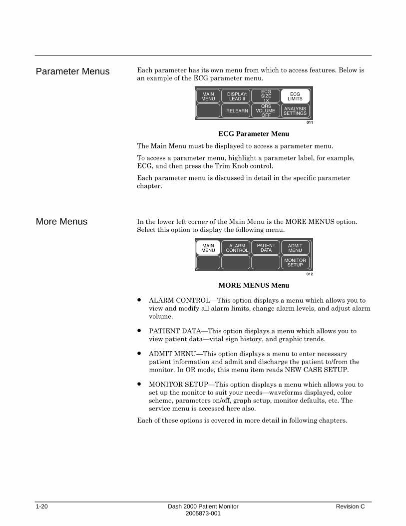
Each parameter has its own menu from which to access features. Below is an example of the ECG parameter menu.
MAINMENU
DISPLAY:LEAD II
RELEARN
ECGSIZE1X
QRSVOLUME:
OFF
ECGLIMITS
ANALYSISSETTINGS
011 ECG Parameter Menu
The Main Menu must be displayed to access a parameter menu.
To access a parameter menu, highlight a parameter label, for example, ECG, and then press the Trim Knob control.
Each parameter menu is discussed in detail in the specific parameter chapter.
In the lower left corner of the Main Menu is the MORE MENUS option. Select this option to display the following menu.
MAINMENU
ALARMCONTROL
PATIENTDATA
ADMITMENU
MONITORSETUP
012 MORE MENUS Menu
• ALARM CONTROL—This option displays a menu which allows you to view and modify all alarm limits, change alarm levels, and adjust alarm volume.
• PATIENT DATA—This option displays a menu which allows you to view patient data—vital sign history, and graphic trends.
• ADMIT MENU—This option displays a menu to enter necessary patient information and admit and discharge the patient to/from the monitor. In OR mode, this menu item reads NEW CASE SETUP.
• MONITOR SETUP—This option displays a menu which allows you to set up the monitor to suit your needs—waveforms displayed, color scheme, parameters on/off, graph setup, monitor defaults, etc. The service menu is accessed here also.
Each of these options is covered in more detail in following chapters.

Revision C Dash 2000 Patient Monitor 1-21 2005873-001
Popup Menus
Scrolling Popup
Pointer Popup
When some menu options are selected, a small menu ”pops up” around the selected menu option. These are called popup menus. There are different types of popup menus. Those most commonly used are described below.
Note that with all popup menus, the original menu remains on the screen but the options are dimmed. The popup menu must be closed before you can select other options from the original menu.
MAINMENU
DISPLAY:LEAD II
RELEARN
ECGSIZE1X
4X2X1X
0.5X
013 Scrolling Popup Menu
All available selections appear with the current selection highlighted. The arrows are also highlighted indicating that the Trim Knob control can be rotated (scrolled) to change the selection. When the Trim Knob control is rotated, the new selection is highlighted and the change occurs immediately on the screen so that the user can see if the selection is appropriate before exiting the popup. Press the Trim Knob control to close the popup menu.
MAINMENU
DETECTPACE:OFF
ECGFILTER
MONITORGOFF
PACE 2PACE 1HELP
>
014
PREV.MENU
QRSWIDTH:
NORMAL
Pointer Popup Menu
All available selections appear and a pointer (>) is displayed. The arrows are highlighted indicating that the Trim Knob control can be rotated to move the pointer to another selection. However, before the change is actually implemented, the Trim Knob control must be pressed. The popup menu closes and the change is in effect.

1-22 Dash 2000 Patient Monitor Revision C 2005873-001
Numeric Popup
Subordinate Menus
MAINMENU
ECGLIMITS
ECG LIMITS
RETURN
HR
UNITS
BPM
LOW
50
HIGH
150>
015 Numeric Popup Menu
The available selections are many; therefore, only the current selection is displayed. The arrows are highlighted indicating the Trim Knob control can be rotated. Rotating the Trim Knob control will change the displayed value in the popup menu. Like the Pointer Popup, the change will not be in effect until the Trim Knob control is pressed.
Whenever possible, short popup menus are displayed when selecting menu options. In some cases, however, a whole new menu is displayed. This is a menu within a menu, or a subordinate menu.
Many, but not all, subordinate menus have the PREV MENU option to allow you to return to the previously displayed menu.
Following is an example of a subordinate menu:
Display the ECG Menu.
MAINMENU
DISPLAY:LEAD II
RELEARN
ECGSIZE1X
QRSVOLUME:
OFF
ECGLIMITS
ANALYSISSETTINGS
016 ECG Parameter Menu
From the ECG Menu select ANALYSIS SETTINGS—the entire ECG Menu is replaced with the subordinate ANALYSIS SETTINGS Menu.
MAINMENU
PREVMENU
ARRHYTHON
ECGFILTER
MONITORGQRS
WIDTHNORMAL
LEADANALYSIS:
MULTI
DETECTPACE:OFF
017 ANALYSIS SETTINGS Menu
Select PREV MENU to redisplay the ECG Menu.

Revision C Dash 2000 Patient Monitor 1-23 2005873-001
Direct Action Menu Options
A direct action menu option, when selected, displays neither a popup menu nor a subordinate menu. The option either turns a feature on or off, or starts a processing function. For example, selecting the SMART BP: ON option from the ART SETTINGS menu turns the Smart BP feature off. In ON/OFF cases, the menu option reflects the current state; selecting it switches to the other state.
MAINMENU
CALIBTRANSDUC
PREVMENU
SMART BP:ON
BPFILTER12Hz
PULSEPATE:
ONDISCONNALARM:
ON
018 SMART BP: ON
MAINMENU
CALIBTRANSDUC
PREVMENU
SMART BP:OFF
BPFILTER12Hz
PULSEPATE:
ONDISCONNALARM:
ON
019 SMART BP: OFF
Other direct action options start a process. For example, selecting the RELEARN option from the ECG parameter menu tells the monitor to immediately start to relearn the patient’s ECG rhythm. You can’t stop these processes as they are short term and stop automatically; therefore, the words identifying the menu option do not change as in ON/OFF actions.

1-24 Dash 2000 Patient Monitor Revision C 2005873-001
Parameter Windows
Parameter windows are displayed on the far right side of the screen, and, when necessary, across the bottom. Every monitored parameter has a parameter window.
Each parameter window has two parts—a parameter label and digital values. Depending on how you have set your defaults, limits and units of measure may be displayed under the parameter label.
ART 200/ 80 S mmHg
RT. 70
7294
136/
020 ART Parameter Window

Revision C Dash 2000 Patient Monitor 1-25 2005873-001
Information Windows
Another window that is sometimes displayed on the screen is called an information window. This large window is superimposed over the middle left portion of the screen. The top real-time waveform is displayed as are 4 parameter windows.
Information windows are displayed when a HELP option is selected and with certain menu options, such as LIMITS. The information window contains instructions or other non-realtime information.
Below is an example of an information window:
ECG 150/ 5021-NOV-2000 17:10
II
DAK.BED 1
60SPO2 105/ 90
RT51* * * 98NBP 200/ 80
S mmHg
ADT
XX
X/
ART 200/ 80S mmHg
RT59
MAINMENU
PREVMENU
SPECIFICTIME
VIEWOLDER
SELECTPARAM
4673
117/
VITAL SIGNS 21-NOV-2000 17:10
ART-SART-DART-MART-RSPO2-%SPO2-RALARMS
21-NOV16:15
60116467258
21-NOV16:30
60116467258
21-NOV16:45
60116467258
21-NOV17:00
60116467258
>
021
HR
Real-TimeWaveforms
InformationWindow
The Vital Signs Information Window
If a popup menu is displayed with the window, you must turn the Trim Knob control to scroll to more information.

1-26 Dash 2000 Patient Monitor Revision C 2005873-001
Trim Knob Control Operation When Setting Alarm Limits
Limits which trigger alarms for monitored parameters can be modified. You should refer to the specific parameter chapter for details. When setting alarm limits, the following information is helpful and applies to most parameters:
The Trim Knob control will always increase (or decrease) the displayed number in increments of one for the first five numbers. Thereafter, it increases (or decreases) in increments of five. There may be situations where the limit you wish to modify does not fall into this incremental sequence. For example, the low heart rate limit default is 50. For your patient, a limit of 44 is desired.
1. Open the ALL LIMITS popup menu and information window.
2. Rotate the Trim Knob control to move the pointer (>) through the list.
3. Press the Trim Knob control when the pointer is in front of HR. The parameter label highlights.
4. Turn the Trim Knob control to highlight the low limit. The number 50 is displayed.
5. Rotate the Trim Knob control until the number reads 45. It will follow this sequence: 49, 48, 47, 46, 45.
NOTE: The next rotation will take the number to 40 which, in this instance, is too low.
6. Press the Trim Knob control and rotate it to highlight the parameter label and press to unhighlight. Then press again, rotate the Trim Knob control to highlight the low limit and press again.
7. Rotate the Trim Knob control to 44.
NOTE: Reselecting the limit always allows you to reset again in increments of one.
8. When all changes are completed, press the Trim Knob control and rotate to highlight the parameter label.
9. Press again and select RETURN with the Trim Knob control. The popup menu and information window close.
The same principle applies when setting limits for other parameters.

Revision C Dash 2000 Patient Monitor 1-27 2005873-001
Graphing (Printing)
Devices
Manual Graphs
Exclusive Graph Control
Alarm Graphs
You can print displayed information using the Dash 2000 monitor's built-in writer or, via the network, using an optional writer and/or an optional laser printer. This manual refers to a PRN 50 and direct digital writer (DDW) as a writer and to a laser printer as a printer.
The writer may be the Dash 2000 monitor's built-in writer or a stand-alone writer connected to another monitor. Your system may include one or more central stations. Some central stations come equipped with a built-in writer. A writer can also be connected to the central station. The optional laser printer always connects to a central station.
Patient waveforms and most information windows can be printed. You choose which waveforms you want to print, to which device you want to print, a duration time, and the speed at which manual graphs are printed. These menu options are all found in the Graph Setup menu. Refer to the Monitor Setup chapter for details.
Waveforms and information windows are printed when the GRAPH GO/ STOP key is pressed. The message ”GRAPHING MANUAL” or ”PRINTING WINDOW” is displayed when a manual graph is requested. There is a setting in the Graph Setup Menu which allows you to set a time for how long a manual graph runs (e.g., continuous, 20 seconds, etc.).
NOTES: A one millivolt ECG signal at normal (1X) size equals 10 millimeters on the graph paper. All waveforms on a graph strip begin with 10 seconds of delayed data. The header information printed with the waveforms is real-time data.
Once a manual graph is started, it can only be stopped from the same source from which it was started or from the Graph Stop key on the writer. This is to prevent two people at different sources starting a graph at the same time, which results in one turning the graph on and the other turning the graph off.
A graph strip is automatically printed when a Crisis or Warning alarm occurs. An arrhythmia alarm graph will run until a normal sinus rhythm is again detected or you manually stop the graph. Any other alarm graph runs for 20 seconds or until you manually stop it.
NOTE: To convert an arrhythmia alarm graph to a manual graph, you must stop the graph using the Graph Stop key on the writer and immediately restart the graph.
In Operating Room mode and Neonatal-ICU mode, the alarm graphing default is off, in Adult ICU mode, it is on. There is a menu option in the Graph Setup menu (ALARM GRAPH) to turn this feature on and off. This can be saved as a Monitor Default.

1-28 Dash 2000 Patient Monitor Revision C 2005873-001
Pressure Scales
Graphing Messages
Graph Header
Invasive pressures will always graph on individual scales as follows:
Displayed Scale Graph Scale
30 0-30 (CVP, LA, RA, ICP,PA) 40 0-45 60 0-60 100 0-90 160 0-150 200, 300 0-300 Auto 0-150 (ART, FEM, UAC, SP)
0-45 (PA, CVP, UVC, RA, LA, ICP)
Following is a list of all graphing messages and what they indicate:
SAVING—the device to which you want to print is busy or for some reason inoperable. If it is an alarm graph, 20 seconds of data is saved until it can print or another alarm graph occurs. The monitor only saves for print the most recent alarm data. A manual graph is saved until you press the GRAPH GO / STOP key or an alarm graph occurs.
GRAPHING MANUAL—a manual graph is in progress. GRAPHING ALARM—a crisis or warning alarm has occurred. An automatic graph is run. PRINTING WINDOW—a manual graph of a printable information window is in progress. PAPER OUT—the writer/printer needs paper or a writer door is open.
NOTE: If saved graph never prints or graph does not print at your central station, check all graph locations, then verify the graph location settings. (Refer to GRAPH LOCATION in the Monitor Setup chapter.)
The graph header which is printed with all patient waveforms, includes:
• type of graph (alarm or manual) • *alarm violation* (if any) • unit name, bed number, and patient name • date and time • patient-monitor type label (ICU has no label) • alarm volume level (%) • graph speed • lead failed (if any) • heart rate • arrhythmia call (if any and arrhythmia is on) • pace mode (if on) • arrhythmia mode (off or lethal) • ECG filter (Hz range) • values for all other monitored parameters

Revision C Dash 2000 Patient Monitor 1-29 2005873-001
Putting the Monitor Into Operation
Monitor Installation and Connection
WARNING Before using the monitor for the first time, please read the information given in chapter 2 ”Safety”.
The operating position does not influence the performance of the monitor in any way.
• Choose a location which affords an unobstructed view of the monitor screen and easy access to the operating controls.
• Set up the device in a location which affords sufficient ventilation. The ventilation openings of the device must not be obstructed (by external equipment, walls or blankets, for instance). The ambient conditions specified in the Technical Specifications chapter must be ensured at all times.
• The Dash 2000 monitor is designed to comply with the requirements of IEC 60601/EN 60601.
• Using the power cord supplied with the monitor, connect it to the power line (the illustration on page 1-3 shows the AC power connector). Use only the original cord or an equivalent one.
WARNING The Dash 2000 must be connected to a properly installed power outlet with protective earth contacts only. If the installation does not provide for a protective earth conductor, disconnect the monitor from the power line and operate it on battery power.
• For measurements in or near the heart we recommend connecting the monitor to the potential equalization system. Use the green and yellow potential equalization cable and connect it to the pin labeled with the
symbol.
• Our customer service engineers can be called in to connect the Dash 2000 to a central station and to the nurse call-system.
WARNING For safety reasons, all connectors for patient cables and sensor leads (with the exception of temperature) are designed to prevent inadvertent disconnection, should someone pull on the leads. Do not route cables in a way that they may present a stumbling hazard. Do not install the monitor in a location where it may drop on the patient. All consoles and brackets used must have a raised edge at the front.

1-30 Dash 2000 Patient Monitor Revision C 2005873-001
Performance Check
• Dash monitors may be shipped with protective covers to protect unused parameter connector inputs from dust and liquids.
NOTE: Do not remove these covers, the parameter connectors do not function.
WARNING After connecting the monitor to the central station and/or nurse-call system, verify the function of the alarm system. This can be done, for instance, by temporarily changing one of the alarm limits to initiate an alarm.
• Turn on the device with the power switch at the front. The green AC ON indicator lights up (page 1-13).
• The monitor display appears after approximately 10 seconds.
After power up and during operation the Dash 2000 runs automatic self- tests. When a malfunction is detected, the monitor displays a message and a prompt, asking whether the user wishes to continue operation.
WARNING If this message appears during operation, it is the physician’s responsibility to decide whether the unit is still suitable for patient monitoring. As a general rule, monitoring with this unit should continue only in extremely urgent cases and under the supervision of a physician. The unit must be repaired before being used again on a patient. If this message appears after power up, the unit must be repaired before being used on a patient.
WARNING After connecting the monitor to a central station, verify the function of the alarm system. This can be done, for instance, by temporarily changing one of the alarm limits to initiate an alarm.
Revision C Dash 2000 Patient Monitor 2-1 2005873-001
2 SAFETY For Your Safety ................................................................................2-2
Intended Use ...............................................................................2-2 Terminology ................................................................................2-2 Monitor Safety ............................................................................2-2 Dangers........................................................................................2-2 Warnings .....................................................................................2-3 Cautions ......................................................................................2-7 Notes ..........................................................................................2-10
Reference Literature......................................................................2-10
Classifications ................................................................................2-11 Underwriters Laboratories, Inc ...............................................2-11 Safe Operating and Handling Conditions...............................2-12 Equipment Symbols..................................................................2-13

2-2 Dash 2000 Patient Monitor Revision C 2005873-001
For Your Safety
Intended Use Terminology Monitor Safety
Dangers
The intended use of the monitoring system is to monitor physiologic parameter data on adult, pediatric, and neonatal patients between all acuity care areas.
Physiologic data includes the parameters covered in this manual. The monitoring system is also intended to provide physiologic data over the Unity network to clinical information systems. This information can be displayed, trended, stored, and printed.
The terms danger, warning, and caution are used throughout this manual to point out hazards and to designate a degree or level of seriousness. Familiarize yourself with their definitions and significance.
Hazard is defined as a source of potential injury to a person.
DANGER indicates an imminent hazard which, if not avoided, will result in death or serious injury.
WARNING indicates a potential hazard or unsafe practice which, if not avoided, could result in death or serious injury.
CAUTION indicates a potential hazard or unsafe practice which, if not avoided, could result in minor personal injury or product/property damage.
NOTE provides application tips or other useful information to assure that you get the most from your equipment.
The safety statements presented in this chapter refer to the equipment in general and, in most cases, apply to all aspects of the monitor. There are additional safety statements in the parameter chapters which are specific to that monitored parameter.
The order in which safety statements are presented in no way implies order of importance.
There are no dangers that refer to the equipment in general. Specific "Danger" statements may be given in the respective sections of this manual.

Revision C Dash 2000 Patient Monitor 2-3 2005873-001
Warnings
WARNINGS
ACCIDENTAL SPILLS — To avoid electric shock or device malfunction liquids must not be allowed to enter the device. If liquids have entered a device, take it out of service and have it checked by a service technician before it is used again.
ACCURACY — If the accuracy of any value displayed on the monitor, central station, or printed on a graph strip is questionable, determine the patient's vital signs by alternative means. Verify that all equipment is working correctly.
ALARMS — Do not rely exclusively on the audible alarm system for patient monitoring. Adjustment of alarm volume to a low level or off during patient monitoring may result in a hazard to the patient. Remember that the most reliable method of patient monitoring combines close personal surveillance with correct operation of monitoring equipment.
After connecting the monitor to the central station and/or nurse-call system, verify the function of the alarm system.
The functions of the alarm system for monitoring the patient must be verified at regular intervals.
BEFORE USE — Before putting the system into operation visually inspect all connecting cables for signs of damage. Damaged cables and connectors must be replaced immediately.
Before using the system, the operator must verify that it is in correct working order and operating condition.
Periodically, and whenever the integrity of the product is in doubt, test all functions.
CABLES — Route all cables away from patient's throat to avoid possible strangulation.
CONDUCTIVE CONNECTIONS — Extreme care must be exercised when applying medical electrical equipment. Many parts of the man/machine circuit are conductive, such as the patient, connectors, electrodes, transducers. It is very important that these conductive parts do not come into contact with other grounded, conductive parts when connected to the insulated patient input of the device. Such contact would bridge the patient's insulation and cancel the protection provided by the insulated input. In particular, there must be no contact of the neutral electrode and ground.

2-4 Dash 2000 Patient Monitor Revision C 2005873-001
WARNINGS
DEFIBRILLATION — Do not come into contact with patients during defibrillation. Otherwise serious injury or death could result.
DISCHARGE TO CLEAR PATIENT DATA — When admitting a new patient, you must clear all previous patient data from the system. To accomplish this, disconnect patient cables, then do a discharge.
DISCONNECTION FROM MAINS — When disconnecting the system from the power line, remove the plug from the wall outlet first. Then you may disconnect the power cord from the device. If you do not observe this sequence, there is a risk of coming into contact with line voltage by inserting metal objects, such as the pins of leadwires, into the sockets of the power cord by mistake.
DISPOSAL — Dispose of the packaging material, observing the applicable waste control regulations and keeping it out of children's reach.
EXPLOSION HAZARD — Do not use this equipment in the presence of flammable anesthetics, vapors or liquids.
INTERFACING OTHER EQUIPMENT — Devices may only be interconnected with each other or to parts of the system when it has been determined by qualified biomedical engineering personnel that there is no danger to the patient, the operator, or the environment as a result. In those instances where there is any element of doubt concerning the safety of connected devices, the user must contact the manufacturers concerned (or other informed experts) for proper use. In all cases, safe and proper operation should be verified with the applicable manufacturer's instructions for use, and system standards IEC 60601-1-1/EN 60601-1-1 must be complied with.

Revision C Dash 2000 Patient Monitor 2-5 2005873-001
WARNINGS
INTRACARDIAC APPLICATION — When applying devices intracardially, electrically conductive contact with parts connected to the heart (pressure transducers, metal tube connections and stopcocks, guide wires, etc.) must be avoided in all cases.
To prevent electrical contact, we recommend the following:
• always wear isolating rubber gloves, • keep parts that are conductively connected to the heart
isolated from ground, • if possible, do not use tube fittings or stopcocks made of
metal.
During intracardiac application of a device, a defibrillator and pacemaker whose proper functioning has been verified must be kept at hand.
LEAKAGE CURRENT TEST — When interfacing with other equipment, a test for leakage current must be performed by qualified biomedical engineering personnel before using with patients.
PATIENT AMBULATION — A patient must be assisted if ambulating with a roll-stand mounted monitor.
POWER SUPPLY — The device must be connected to a properly installed power outlet with protective earth contacts only. If the installation does not provide for a protective earth conductor, disconnect the monitor from the power line and operate it on battery power, if possible.
All devices of a system must be connected to the same power supply circuit. Devices which are not connected to the same circuit must be electrically isolated when operated (electrically isolated RS232 interface).
PROTECTED LEADWIRES — Only use protected leadwires and patient cables with this monitor. The use of unprotected leadwires and patient cables creates the potential for making an electrical connection to ground or to a high voltage power source which can cause serious injury or death to the patient.
Unprotected Leadwire Protected Leadwire002A

2-6 Dash 2000 Patient Monitor Revision C 2005873-001
WARNINGS
RATE METERS — Keep pacemaker patients under close observation. Rate meters may continue to count the pacemaker rate during cardiac arrest and some arrhythmias. Therefore, do not rely entirely on rate meter alarms.
SITE REQUIREMENTS — For safety reasons, all connectors for patient cables and sensor leads (with the exception of temperature) are designed to prevent inadvertent disconnection, should someone pull on them. Do not route cables in a way that they may present a stumbling hazard. For devices installed above the patient, adequate precautions must be taken to prevent them from dropping on the patient.

Revision C Dash 2000 Patient Monitor 2-7 2005873-001
Cautions
CAUTIONS
ACCESSORIES (SUPPLIES) — To ensure patient safety, use only parts and accessories manufactured or recommended by GE Medical Systems Information Technologies.
Parts and accessories used must meet the requirements of the applicable IEC 60601 series safety standards and essential performance standards, and/or the system configuration must meet the requirements of the IEC 60601-1-1 medical electrical systems standard.
ACCESSORIES (EQUIPMENT) — The use of ACCESSORY equipment not complying with the equivalent safety requirements of this equipment may lead to a reduced level of safety of the resulting system. Consideration relating to the choice shall include:
• use of the accessory in the PATIENT VICINITY; and • evidence that the safety certification of the ACCESSORY
has been performed in accordance to the appropriate IEC 60601-1 and/or IEC 60601-1-1 harmonized national standard.
BATTERY POWER — The device is equipped with a battery pack. The battery discharges even when the device is not in use. Store the device with a fully charged battery and check the battery status of devices in storage once a month.
BEFORE INSTALLATION — Compatibility is critical to safe and effective use of this device. Please contact your local sales or service representative prior to installation to verify equipment compatibility.
DEFIBRILLATOR PRECAUTIONS — Patient signal inputs labeled with the CF and BF symbols with paddles are protected against damage resulting from defibrillation voltages. To ensure proper defibrillator protection, use only the recommended cables and leadwires.
Proper placement of defibrillator paddles in relation to the electrodes is required to ensure successful defibrillation.

2-8 Dash 2000 Patient Monitor Revision C 2005873-001
CAUTIONS
DISPOSABLES — Disposable devices are intended for single use only. They should not be reused as performance could degrade or contamination could occur.
DISPOSAL — At the end of its service life, the product described in this manual, as well as its accessories, must be disposed of in compliance with the guidelines regulating the disposal of such products. If you have questions concerning disposal of products, please contact GE Medical Systems Information Technologies or its representatives.
ELECTROCAUTERY PRECAUTIONS — To prevent skin burns, apply electrocautery electrodes as far as possible from all other electrodes, a distance of at least 15 cm/6 in. is recommended.
EMC — Magnetic and electrical fields are capable of interfering with the proper performance of the device. For this reason make sure that all external devices operated in the vicinity of the monitor comply with the relevant EMC requirements. X-ray equipment or MRI devices are a possible source of interference as they may emit higher levels of electromagnetic radiation. Also, keep cellular phones or other telecommunication equipment away from the monitor.
INSTRUCTIONS FOR USE — For continued safe use of this equipment, it is necessary that the listed instructions are followed. However, instructions listed in this manual in no way supersede established medical practices concerning patient care.
LOSS OF DATA — Should the monitor at any time temporarily lose patient data, the potential exists that active monitoring is not being done. Close patient observation or alternate monitoring devices should be used until monitor function is restored.
If the monitor does not automatically resume operation within 60 seconds, power cycle the monitor using the power on/off switch. Once monitoring is restored, you should verify correct monitoring state and alarm function.
MAINTENANCE — Regular preventive maintenance should be carried out annually (Technical Inspections). You are responsible for any requirements specific to your country.

Revision C Dash 2000 Patient Monitor 2-9 2005873-001
CAUTIONS
MPSO — The use of a multiple portable socket outlet (MPSO) for a system will result in an enclosure leakage current equal to the sum of all individual earth leakage currents of the system if there is an interruption of the MPSO protective earth conductor. Do not use an additional extension cable with the MPSO as it will increase the chance of the single protective earth conductor interruption.
NEGLIGENCE — GE Medical Systems Information Technologies does not assume responsibility for damage to the equipment caused by improperly vented cabinets, improper or faulty power, or insufficient wall strength to support equipment mounted on such walls.
OPERATOR — Medical technical equipment such as this monitor/monitoring system must only be used by persons who have received adequate training in the use of such equipment and who are capable of applying it properly.
POWER REQUIREMENTS — Before connecting the device to the power line, check that the voltage and frequency ratings of the power line are the same as those indicated on the unit's label. If this is not the case, do not connect the system to the power line until you adjust the unit to match the power source.
In U.S.A., if the installation of this equipment will use 240V rather than 120V, the source must be a center-tapped, 240V, single-phase circuit.
RESTRICTED SALE—U.S. federal law restricts this device to sale by or on the order of a physician.
SUPERVISED USE—This equipment is intended for use under the direct supervision of a licensed health care practitioner.
VENTILATION REQUIREMENTS—Set up the device in a location which affords sufficient ventilation. The ventilation openings of the device must not be obstructed. The ambient conditions specified in the technical specifications must be ensured at all times.

2-10 Dash 2000 Patient Monitor Revision C 2005873-001
Notes
Reference Literature
• Put the monitor in a location where you can easily see the screen and access the operating controls.
• This product is not likely to cause abnormal operation of other patient-connected equipment such as cardiac pacemaker or other electrical stimulators. Exceptions are noted in the section “Detect Pace”, if applicable.
• This product is protected against the effects of cardiac defibrillator discharges to ensure proper recovery, as required by test standards. (The screen may blank during a defibrillator discharge but recovers within seconds as required by test standards.)
Medical Device Directive 93/42/EEC
EN 60601-1/1990 + A1: 1993 + A2: 1995: Medical electrical equipment. General requirements for safety
EN 60601-1-1/9.1994 + A1 12.95: General requirements for safety. Requirements for the safety of medical electrical systems.
IEC Publication 513/1994: Fundamental aspects of safety standards for medical equipment.

Revision C Dash 2000 Patient Monitor 2-11 2005873-001
Classifications
Underwriters Laboratories, Inc.
The Dash 2000 Patient Monitor is classified, according to IEC 60601-1 as:
Type of protection against electric shock:
I
Degree of protection against electric shock:
CF—ECG, Temp, Resp, BP
BF—NBP, SpO2
Degree of protection against harmful ingress of water:
Ordinary Equipment (enclosed equipment without protection against ingress of water)
Degree of safety of application in the presence of a flammable anesthetic –mixture with air or with oxygen or nitrous oxide:
Not suitable
I: Class I equipment
CF: Type CF applied part
BF: Type BF applied part
Not suitable: Equipment not suitable for use in the presence of flammable anesthetic mixture with air or with oxygen or nitrous oxide.
CLASSIFIED
C USR
Classified by Underwriters Laboratories Inc. with respect to electric shock, fire, mechanical and other specified hazards, only in accordance with UL 2601-1, CAN/CSA C22.2 No. 601.1, IEC 60601-1, and, if required, IEC 60601-2-27, IEC 60601-2-30, IEC 60601-2-34, IEC 60601-1-1.

2-12 Dash 2000 Patient Monitor Revision C 2005873-001
Safe Operating and Handling Conditions
Method(s) of sterilization or disinfection recommended by the manufacturer:
Sterilization: not applicable
Disinfection: see "Maintenance -> General Cleaning"
Mode of operation: Continuous operation
Electromagnetic interference No cordless telephone nearby
Electrosurgical interference damage
No damage
Diathermy instruments influence
Displayed values and prints may be disturbed or erroneous during diathermy.
Defibrillation shocks The monitor specifications fulfill the requirements of EC13, IEC 60601-2-27, -30, 34 and prEN 865.
Auxiliary outputs The system must fulfill the requirements of standard IEC 60601-1-1.

Revision C Dash 2000 Patient Monitor 2-13 2005873-001
Equipment Symbols
NOTE: The rating of protection
against electric shock (indicated by symbol for CF or BF) is achieved only when used with patient applied parts recommended by GE Medical Systems Information Technologies.
NOTE: Some symbols may not appear on all equipment.
ATTENTION: Consult accompanying documents
CAUTION: To reduce the risk of electric shock, do NOT remove cover. Refer servicing to qualified service personnel.
TYPE CF APPLIED PART: Insulated (floating) applied part suitable for intentional external and internal application to the patient including direct cardiac application. "Paddles" outside the box indicate the applied part is defibrillator proof.
Medical Standard Definition: F-type applied part (floating/insulated) complying with the specified requirements of IEC 60601-1/UL 2601-1/CSA 601.1 Medical Standards to provide a higher degree of protection against electric shock than that provided by type BF applied parts.
TYPE BF APPLIED PART: Insulated (floating) applied part suitable for intentional external and internal application to the patient excluding direct cardiac application. "Paddles" outside the box indicate the applied part is defibrillator proof.
Medical Standard Definition: F-type applied part (floating/insulated) complying with the specified requirements of IEC 60601-1/UL 2601-1/CSA 601.1 Medical Standards to provide a higher degree of protection against electric shock than that provided by type B applied parts.
TYPE B APPLIED PART: Non-insulated applied part suitable for intentional external and internal application to the patient excluding direct cardiac application.
Medical Standard Definition: Applied part complying with the specified requirements of IEC 60601-1/UL 2601-1/CSA 601.1 Medical Standards to provide protection against electric shock, particularly regarding allowable leakage current.
Fuse
Equipotentiality
Alternating current (AC)
Power; I = ON; O = OFF
Indicates where to press to open the door on the DDW.

2-14 Dash 2000 Patient Monitor Revision C 2005873-001
For your notes

Revision C Dash 2000 Patient Monitor 3-1 2005873-001
3 ADMIT DISCHARGE About Admitting ..............................................................................3-2
You Must Admit to Activate Alarms .........................................3-2 Monitors are Used in Different Ways........................................3-2
Guidelines When Doing Combination Monitoring ..............3-3 For Which Application is the Monitor Set?...............................3-3
Getting to the Admit Menu .............................................................3-4
Standard Admit Menu.....................................................................3-5
Rover Admit Menu...........................................................................3-6
Combo Admit Menu .........................................................................3-7
Rover Combo Admit Menu ..............................................................3-8
Admit Menu Options .......................................................................3-9 Admit Info ...................................................................................3-9
Change Admit Info ..............................................................3-10 Request Admit Info..............................................................3-11 Save Admit Info ...................................................................3-11 Weight and Height ..............................................................3-11 Age ....................................................................................3-11
Admit Patient............................................................................3-12 Admit Patient.......................................................................3-12 New Case..............................................................................3-12
Set Unit Name ..........................................................................3-13 Set Bed Number........................................................................3-14 Set Graph Location...................................................................3-15 ECG Source ...............................................................................3-15
About Discharging .........................................................................3-16 Discharge Patient .....................................................................3-16
Standard and Rover Admit Menu ......................................3-16 Combo and Rover Combo ....................................................3-17 New Case..............................................................................3-17

3-2 Dash 2000 Patient Monitor Revision C 2005873-001
About Admitting
You Must Admit to Activate Alarms Monitors are Used in Different Ways
Admitting a patient to the monitor is important. Audible alarms are off and there will be no alarm graphs and alarm history until the monitor is in the admit mode. The following message is displayed near the middle of the screen to alert you to admit your patient:
ALL ALARMS OFF ADMIT PATIENT TO ACTIVATE ALARMS
What you do to admit a patient to the monitor depends on how the monitor is used. We have defined four ways in which the monitor is used:
STANDARD—This application uses a monitor mounted in the room. It does not accommodate telemetry. A network connection is not required unless you have a central station.
ROVER—With this application you can move, or ”rove,” the monitor to the patient, rather than moving the patient to a monitored room. It does not accommodate telemetry. A network connection is not required unless you have a central station.
COMBO—This application provides the option to acquire ECG data from either the monitor or from a telemetry receiver cabinet. This ECG data acquisition capability enhances basic telemetry monitoring by providing additional access to all of the available parameters from the monitor. A network connection is required.
ROVER COMBO—This application combines the mobility feature of Rover monitoring with the telemetry compatibility of Combo monitoring. A network is required.
It is determined at the time of installation which application applies. At that time a menu option in the service mode is used to set your monitor for one of the above applications. The information that is necessary for successful admission to the monitor and the network is then provided in the Admit Menu.
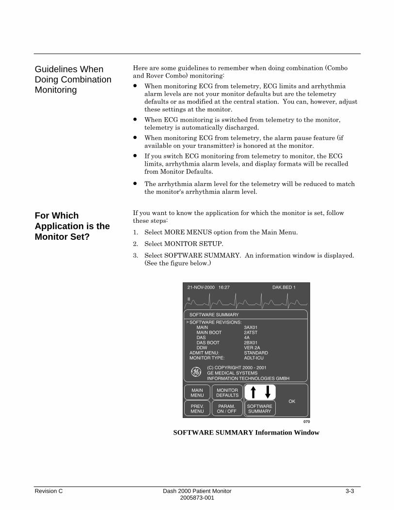
Revision C Dash 2000 Patient Monitor 3-3 2005873-001
Guidelines When Doing Combination Monitoring
For Which Application is the Monitor Set?
Here are some guidelines to remember when doing combination (Combo and Rover Combo) monitoring: • When monitoring ECG from telemetry, ECG limits and arrhythmia
alarm levels are not your monitor defaults but are the telemetry defaults or as modified at the central station. You can, however, adjust these settings at the monitor.
• When ECG monitoring is switched from telemetry to the monitor, telemetry is automatically discharged.
• When monitoring ECG from telemetry, the alarm pause feature (if available on your transmitter) is honored at the monitor.
• If you switch ECG monitoring from telemetry to monitor, the ECG limits, arrhythmia alarm levels, and display formats will be recalled from Monitor Defaults.
• The arrhythmia alarm level for the telemetry will be reduced to match the monitor's arrhythmia alarm level.
If you want to know the application for which the monitor is set, follow these steps:
1. Select MORE MENUS option from the Main Menu.
2. Select MONITOR SETUP.
3. Select SOFTWARE SUMMARY. An information window is displayed. (See the figure below.)
21-NOV-2000 16:27
II
DAK.BED 1
SOFTWARE SUMMARY
SOFTWARE REVISIONS:MAINMAIN BOOTDASDAS BOOTDDW
ADMIT MENU:MONITOR TYPE:
3AX012ATST4A2BX01VER 2ASTANDARDADLT-ICU
MAINMENU
MONITORDEFAULTS
PREV.MENU
SOFTWARESUMMARY
OKPARAM.
ON / OFF
>
070
(C) COPYRIGHT 2000 - 2001GE MEDICAL SYSTEMSINFORMATION TECHNOLOGIES GMBH
SOFTWARE SUMMARY Information Window

3-4 Dash 2000 Patient Monitor Revision C 2005873-001
Getting to the Admit Menu
1. Select MORE MENUS from the Main Menu.
2. Select ADMIT MENU to display one of the following menus.
MAINMENU
ALARMCONTROL
PATIENTDATA
ADMITMENU
MONITORSETUP
023 Adult-ICU and Neonatal-ICU Modes
MAINMENU
ALARMCONTROL
PATIENTDATA
NEW CASESETUP
MONITORSETUP
024 Operating Room Mode
3. Select ADMIT MENU or NEW CASE SETUP to display the Admit Menu. The admit menu displayed depends on how your monitor has been set up. The following pages describe the various admit menus.

Revision C Dash 2000 Patient Monitor 3-5 2005873-001
Standard Admit Menu
With the Standard application, the monitor is permanently assigned to a room. The unit name and bed number are assigned during installation. The options you may need to adjust/enter are shown in the admit menu below.
MAINMENU
ADMITINFO
XXXPATIENT
PREV.MENU
025 ICU ADMIT Menu – STANDARD application
NOTE: XXX=ADMIT if patient is discharged, DISCHARG otherwise.
MAINMENU
ADMITINFO
NEWCASE
PREV.MENU
026 OR ADMIT Menu – STANDARD Application
ADMIT INFO—opens the admit information window and popup menu; refer to section Admit Info later in this chapter.
ADMIT PATIENT–a direct action menu option that admits the patient.
DISCHARG PATIENT—opens a popup menu to confirm the discharge of the patient.
NEW CASE—a direct action option which discharges the patient’s information and, with no additional steps, readies the monitor for the next patient (new admission).
NOTE: This option is found in OR mode only.
Refer to this chapter, Admit Menu Options, if you need more details on these menu options.

3-6 Dash 2000 Patient Monitor Revision C 2005873-001
Rover Admit Menu
With the Rover application, the monitor may be on a cart which allows you to move it from one room to another. The unit name and bed number, in some cases, may need to be changed so they are included as options in the admit menu.
MAINMENU
ADMITINFO
XXXPATIENT
PREV.MENU
SETUNIT
NAME
SETBED
NUMBER
SETGRAPH
LOCATION
027 ICU ADMIT Menu – Rover Application
NOTE: XXX=ADMIT if patient is discharged, DISCHARG otherwise.
MAINMENU
ADMITINFO
NEWCASE
PREV.MENU
SETUNIT
NAME
SETBED
NUMBER
SETGRAPH
LOCATION
028 OR ADMIT Menu – Rover Application
SET UNIT NAME—verify or change the unit name. The correct unit name is essential for recognition at a central station and other network devices. SET BED NUMBER—verify or change the assigned bed number. The correct bed number is essential for recognition at a central station and other network devices. SET GRAPH LOCATION—option displays a menu which allows you to choose writers for alarm and manual graphs; refer to sections Monitor Setup, Graph Setup, Set Graph Location.
ADMIT INFO—opens the admit information window and popup menu; refer to section Admit Info later in this chapter.
ADMIT PATIENT–a direct action menu option that admits the patient.
DISCHARG PATIENT—opens a popup menu to confirm the discharge of the patient.
NEW CASE—a direct action option which discharges the patient’s information and, with no additional steps, readies the monitor for the next patient (new admission).
NOTE: This option is found in OR mode only.
Refer to this chapter, Admit Menu Options, if you need more details on these menu options.

Revision C Dash 2000 Patient Monitor 3-7 2005873-001
Combo Admit Menu
With the Combo application, the monitor is permanently assigned to a room, and you have the ability to obtain patient ECG data from a monitor or from a telemetry transmitter.
NOTE: A room must have network cable in order to use telemetry.
The unit name and bed number are assigned during installation. The options you may need to adjust/enter are shown in the admit menu below.
MAINMENU
ADMITINFO
XXXPATIENT
PREV.MENU
ECGSOURCE:MONITOR
029 ICU Admit Menu—Combo Application
NOTE: XXX=ADMIT if patient is discharged, DISCHARG otherwise.
NOTE: It is not likely that this application is used when the monitor is set for Operating Room mode. However, the admit menu would look just like this one.
ECG SOURCE—choose either the monitor or a telemetry transmitter from which to receive the patient’s parameter data.
ADMIT INFO—opens the admit information window and popup menu; refer to section Admit Info later in this chapter.
ADMIT PATIENT–a direct action menu option that admits the patient.
DISCHARG PATIENT—opens a popup menu to confirm the discharge of the patient.
Refer to this chapter, Admit Menu Options, if you need more details on these menu options.
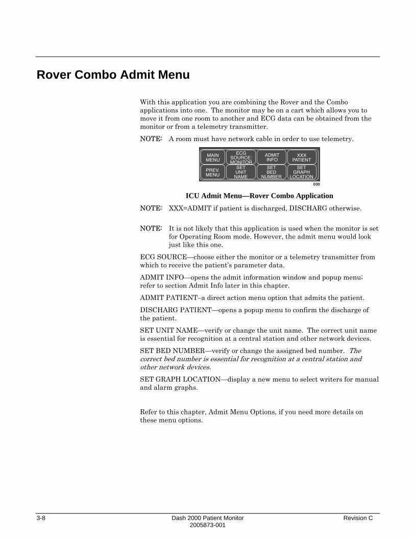
3-8 Dash 2000 Patient Monitor Revision C 2005873-001
Rover Combo Admit Menu
With this application you are combining the Rover and the Combo applications into one. The monitor may be on a cart which allows you to move it from one room to another and ECG data can be obtained from the monitor or from a telemetry transmitter.
NOTE: A room must have network cable in order to use telemetry.
MAINMENU
ADMITINFO
XXXPATIENT
PREV.MENU
SETUNIT
NAME
SETBED
NUMBER
SETGRAPH
LOCATION
030
ECGSOURCE:MONITOR
ICU Admit Menu—Rover Combo Application
NOTE: XXX=ADMIT if patient is discharged, DISCHARG otherwise. NOTE: It is not likely that this application is used when the monitor is set
for Operating Room mode. However, the admit menu would look just like this one.
ECG SOURCE—choose either the monitor or a telemetry transmitter from which to receive the patient’s parameter data.
ADMIT INFO—opens the admit information window and popup menu; refer to section Admit Info later in this chapter.
ADMIT PATIENT–a direct action menu option that admits the patient.
DISCHARG PATIENT—opens a popup menu to confirm the discharge of the patient.
SET UNIT NAME—verify or change the unit name. The correct unit name is essential for recognition at a central station and other network devices.
SET BED NUMBER—verify or change the assigned bed number. The correct bed number is essential for recognition at a central station and other network devices. SET GRAPH LOCATION—display a new menu to select writers for manual and alarm graphs.
Refer to this chapter, Admit Menu Options, if you need more details on these menu options.

Revision C Dash 2000 Patient Monitor 3-9 2005873-001
Admit Menu Options
Admit Info
This menu option is found in all the admit menus.
It opens the Admit Info information window and popup menu.
The Admit Info popup menu allows you to view, change, request or save information pertinent to the monitored patient.
Below is an example of the Admit Info information window:
21-NOV-1998 16:27
II
DAK.BED 1
MANUAL ADMIT INFORMATION
RETURNLAST NAMEFIRST NAMEPATIENT IDSEXBIRTH DATEAGEHEIGHTWEIGHT
>
034 ADMIT INFO Information Window
The RETURN option appears after selecting CHANGE ADMIT INFO. Then two additional items, LOCATION ID and SITE NUMBER, are accessible when scrolling through the window (not functional in Dash 2000).
Depending on the monitor setup, different Admit Info popup menus are displayed:
MAINMENU
REQUESTADMITINFO
PREV.MENU
WEIGHT:KG
CHANGEADMITINFO
HEIGHT:INCHES
SAVEADMITINFO
031 ADMIT INFO Menu—Adult ICU / OR
MAINMENU
REQUESTADMITINFO
PREV.MENU
WEIGHT:KG
CHANGEADMITINFO
HEIGHT:INCHES
SAVEADMITINFO
AGE:DAYS
032 ADMIT INFO Menu—Neonatal ICU

3-10 Dash 2000 Patient Monitor Revision C 2005873-001
Change Admit Info
The CHANGE ADMIT INFO option allows you to change or enter information pertinent to the monitored patient.
1. Select CHANGE ADMIT INFO option from the Admit Info Menu. The RETURN option and a pointer (>) are displayed in the Admit Info information window.
21-NOV-1998 16:27
II
DAK.BED 1
MANUAL ADMIT INFORMATION
RETURNLAST NAMEFIRST NAMEPATIENT IDSEXBIRTH DATEAGEHEIGHTWEIGHT
>
034 CHANGE ADMIT INFO Window
2. Rotate the Trim Knob control to move the pointer (>) and scroll through the list; press to select an item you want to change (see below).
3. When all information is entered select RETURN. A prompt appears giving you the option to SAVE or DO NOT SAVE CHANGES. Selecting an option will close the popup and return you to the Change Admit Info menu.
Name: enter up to 13 characters for each name. The name (at least part if not all) is displayed on the monitor and central station, and printed on all graph headers.
Patient ID: enter up to 13 characters. This is important information to enter if you have a MUSE system or a Solar Lab Access Server. If not entered the monitor uses a default of all 9's for MUSE storage.
Sex: select male or female.
Birth Date: enter the patient's birth date. AGE is automatically calculated.
Age: automatically calculated when the birth date is entered. Age is calculated in years for adults and weeks, days, or years for neonates (weeks if ages is greater than 14 days but less than 2 years). If you enter an age, the birth date is calculated with current day and month and appropriate year.
Height, Weight: enter the patient's height and weight.
Location ID: enter the location identification for your MUSE system if you have one (not used in current SW version).
Site Number: if your institution has multiple buildings, a site number may be necessary. A Muse system may be used for site numbering (not used in current SW version).

Revision C Dash 2000 Patient Monitor 3-11 2005873-001
Request Admit Info
Save Admit Info
Weight and Height
Age
If your monitoring system includes a Lab Access Server with an interface to hospital information, selecting this option will display patient information that was entered. (See the figure below.) If your system does not have this equipment, a message is displayed below the menu when you attempt to select this option.
AUTOMATIC ADMIT INFORMATION
LAST NAMEFIRST NAMEPATIENT IDSEXBIRTH DATEAGEHEIGHTWEIGHTLOCATION IDSITE NUMBER
DAYTONRAY333-33-333MALE14 JAN 194850
Name, ID, Sex, and Birth Datecome from hospital information.
Age is calculated if a birth datehas been entered.The remaining information willbe displayed if previouslyentered. If necessary you canadd to or change the informationdisplayed.
034A
MAINMENU
REQUESTADMITINFO
PREV.MENU
WEIGHT:KG
CHANGEADMITINFO
HEIGHT:INCHES
REQUEST ADMIT INFO Information Menu
Verify the accuracy of any displayed information. Use the CHANGE ADMIT INFO option if any information needs to be corrected or additional information entered.
NOTE: If you change any information which was supplied automatically, you may have to notify the appropriate hospital personnel.
This option is displayed only if your monitoring system includes a Lab Access Server with an interface to hospital information. Selecting this option will save patient information entered at bedside.
WEIGHT and HEIGHT—these options change the units of measure for weight and height.
AGE—this option only appears when the monitor is set for Neonatal-ICU mode. Select it to switch age between weeks, days, or years.
3-12 Dash 2000 Patient Monitor Revision C 2005873-001
Admit Patient
Admit Patient
New Case
Depending on how your monitor is set up, you will see either ADMIT PATIENT or NEW CASE.
This menu option is a direct action menu option which admits the patient to the monitor. Simply select the key to admit the patient.
This menu option is found only when the monitor is set for Operating Room mode and Standard or Rover admit menu.
It is a direct action menu option which, when selected, does both a discharge and immediate admit.
All patient data from the previous patient is erased, the screen blanks for a few seconds, and then the monitor is ready for the next patient.

Revision C Dash 2000 Patient Monitor 3-13 2005873-001
Set Unit Name
This menu option is found in the Rover and Rover Combo admit menus.
The unit name is very important for sending information to central stations and writers.
Look at the top of the display. The unit name (CCU, ICU, etc.) is displayed on the right. Is this the unit name which identifies your unit?
ECG 150/ 5021-NOV-1998 16:27
II
SPO2
ART
160
DAK.BED 1
60SPO2 105/ 90
RT51* * * 98NBP 200/ 80
S mmHg
ADT
XX
X/
ART 200/ 80S mmHg
4673
117/TP 420/ 300
°C
36.6MORE
MENUS
+ -
0
RT59
The unit name appears here
036 Location of Unit Name on the Monitor
If it is not the correct unit name follow this procedure to change it:
1. Select SET UNIT NAME option from the Admit Menu. An information window is displayed with the available unit names.
21-NOV-2000 16:27
II
DAK.BED 1
SELECT A CARE UNIT
RETURNNICUPICUSICU
MAINMENU
XXXPATIENT
SETUNITNAME
SETGRAPH
LOCATION
PREV.MENU
>
037 SET UNIT NAME Popup Menu and Information Window
2. Rotate the Trim Knob control to move the pointer (>) in front of the correct unit name.
3. Press the Trim Knob control. The information window closes and the new unit name appears at the top of the monitor.
NOTE: If the monitor is not on the network, a text entry popup menu will open.

3-14 Dash 2000 Patient Monitor Revision C 2005873-001
Set Bed Number
This menu option is found in Rover and Rover Combo admit menus.
Another essential element to recognize the monitor on the network is the bed number. Look to the right of the unit name on the display. The bed number assigned to this monitor is displayed.
ECG 150/ 5021-NOV-1998 16:27
II
DAK.BED 1
60SPO2 105/ 90
98
Bed number appears here
038 Location of Bed Number on the Monitor
Follow this procedure to confirm that the bed number is correct:
1. Select SET BED NUMBER from the Admit Menu. A popup menu and information window are displayed.
21-NOV-2000 16:27
II
DAK.BED 1
CONFIRM BED NUMBER:
CREATE NEW BEDBED1BED2BED3BED4BED5BED6
MAINMENU
SETUNITNAME
SETBED
NUMBERXXXXPREV.
MENU
>
039 SET BED NUMBER Popup Menu and Information Window
2. Use the Trim Knob control to move the pointer in front of the correct bed number.
3. If the bed number you need is not listed, select CREATE NEW BED. A text entry popup menu opens which works just like that for setting patient name.
NOTE: If the monitor is not on the network, a text entry popup menu will open.

Revision C Dash 2000 Patient Monitor 3-15 2005873-001
Set Graph Location
ECG Source
The GRAPH LOCATION option display a menu which allows you to choose writers for alarm and manual graphs. This option is used mostly if the Dash does not have the optional built-in writer. The graph location should be changed whenever the Dash is moved from one unit to another. Refer to GRAPH LOCATION in the Monitor Setup chapter for more detailed information.
This menu option is found in Combo and Rover Combo admit menus.
This menu option, which is unique to those monitors which can obtain parameter data from telemetry or the monitor, is used to tell the monitor where to get the parameter information.
Follow this procedure:
1. Select ECG SOURCE option from the Admit Menu. A popup menu and an information window are displayed.
21-NOV-2000 16:27
II
DAK.BED 1
SELECT ECG SOURCE
MONITOR331446447783
MAINMENU
ECGSOURCE
PREV.MENU
>
040
ADMITPATIENT
SETGRAPH
LOCATION
ECG SOURCE Popup Menu and Information Window
The information window lists the possible sources from which the parameter data can be obtained. The transmitter numbers listed are those transmitters assigned to the unit.
2. Rotate the Trim Knob control to move the pointer (>) in front of the source of choice. Select MONITOR if your patient’s ECG cable is connected to the monitor. If your patient is wearing a telemetry transmitter, select the transmitter number that matches the one on the back of the transmitter.
3. Press the Trim Knob control to close the popup menu and information window. If you choose a transmitter number, that number (TTX) needs to be admitted before it will appear in the ECG parameter window.
4. Select ADMIT PATIENT to admit the transmitter. The TTX number now appears in the ECG parameter window.
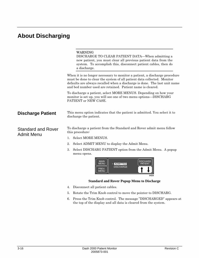
3-16 Dash 2000 Patient Monitor Revision C 2005873-001
About Discharging
Discharge Patient
Standard and Rover Admit Menu
WARNING DISCHARGE TO CLEAR PATIENT DATA—When admitting a new patient, you must clear all previous patient data from the system. To accomplish this, disconnect patient cables, then do a discharge.
When it is no longer necessary to monitor a patient, a discharge procedure must be done to clear the system of all patient data collected. Monitor defaults are always recalled when a discharge is done. The last unit name and bed number used are retained. Patient name is cleared.
To discharge a patient, select MORE MENUS. Depending on how your monitor is set up, you will see one of two menu options—DISCHARG PATIENT or NEW CASE.
This menu option indicates that the patient is admitted. You select it to discharge the patient.
To discharge a patient from the Standard and Rover admit menu follow this procedure:
1. Select MORE MENUS.
2. Select ADMIT MENU to display the Admit Menu.
3. Select DISCHARG PATIENT option from the Admit Menu. A popup menu opens.
MAINMENU
DISCHARGPATIENT
PREV.MENU
DISCHARGE
042A
ADMITTED>
Standard and Rover Popup Menu to Discharge
4. Disconnect all patient cables.
5. Rotate the Trim Knob control to move the pointer to DISCHARG.
6. Press the Trim Knob control. The message ”DISCHARGED” appears at the top of the display and all data is cleared from the system.

Revision C Dash 2000 Patient Monitor 3-17 2005873-001
Combo and Rover Combo
New Case
To discharge a patient from the Combo and Rover Combo admit menu follow this procedure:
1. Select MORE MENUS.
2. Select ADMIT MENU to display the Admit Menu.
3. Select DISCHARG PATIENT to display the following popup menu.
MAINMENU
DISCHARGPATIENT
PREV.MENU
> RETURN MONITOR TELEMETRY BOTH
042B Combo and Rover Combo Popup Menu to Discharge
4. Rotate the Trim Knob control to move the pointer (>) in front of: a. RETURN if you do not want to discharge.
b. MONITOR to discharge patient from monitor only. If ECG was from telemetry, telemetry will remain admitted, but will not be monitored by this monitor. The central station will continue to monitor the telemetry.
c. TELEMETRY to discharge patient from telemetry only. ECG will automatically switch to the monitor.
d. BOTH to discharge patient from telemetry and monitor. If ECG was from the monitor, BOTH will only affect the monitor.
5. Press the Trim Knob control to complete the discharge.
This menu option is displayed only when the monitor is set for Operating Room mode and is found in Standard and Rover admit menus.
This menu option clears patient information from the monitor. With no additional steps, the monitor is ready for the next patient (new admission).
1. Select MORE MENUS.
2. Select NEW CASE SETUP to display the Admit Menu.
3. Disconnect patient cables.
4. Select NEW CASE from the Admit Menu.
5. Press the Trim Knob control. Patient information clears and the monitor is automatically put in the admit state, ready for the next patient. (You will never see the ”DISCHARGED” message displayed.)

3-18 Dash 2000 Patient Monitor Revision C 2005873-001
For your notes

Revision C Dash 2000 Patient Monitor 4-1 2005873-001
4 ALARM CONTROL Smart Alarms...................................................................................4-2
Alarm Structure ...............................................................................4-3 Patient Status Alarms................................................................4-3 System Status Alarms................................................................4-4
Controlling Audio Alarms ...............................................................4-5 Silencing an Alarm for One Minute ..........................................4-5 Pausing Alarms...........................................................................4-5 Turning Alarm Volume Off Permanently .................................4-5
Alarm Control Menu........................................................................4-6 All Limits.....................................................................................4-7
Viewing an All Limits Screen ...............................................4-7 Changing a Limit in the All Limits Screen..........................4-8
Alarm Graph ...............................................................................4-9 Alarm Volume ...........................................................................4-10 Parameter Alarm Level ............................................................4-11 Arrhythmia Alarm Level..........................................................4-12

4-2 Dash 2000 Patient Monitor Revision C 2005873-001
Smart Alarms
Alarm processing is not activated until the monitor has detected valid physiologic data from the patient. This allows you to admit a patient and proceed with necessary patient connections without bothersome alarm tones. If during monitoring a new parameter is added, for example, pulse oximetry, the alarm processing for that parameter will not be active until valid physiologic data is detected.
NOTE: To properly use the smart alarm feature, be sure to remove all patient cables to the monitor prior to discharging. This assures that no data is seen after a discharge.
WARNING After an interruption of the electric power supply (e.g. for an emergency power test) it is necessary to check whether the alarm processing is active again and whether asystole has occurred while the power supply was interrupted.

Revision C Dash 2000 Patient Monitor 4-3 2005873-001
Alarm Structure
Patient Status Alarms
The alarm structure of the monitor is divided into two classifications:
• Patient Status Alarms and
• System Status Alarms.
Within each classification there are levels which correlate to how severe the condition is that is causing the alarm. The levels and how the monitor responds to each are described below. Patient status alarms can, in most cases, be moved from one level to another. Refer to this chapter, Arrhythmia Alarm Level and Parameter Alarm Level.
Patient status alarms are triggered by patient condition which exceeds parameter limits, or by an arrhythmia condition. Patient status alarms provide you the highest priority information.
The levels within the Patient Status Alarm category and how the monitor responds to each is shown in the following chart. The chart begins with the most critical type of alarm (Crisis) and ends with the least critical type of alarm (Message).
NOTE: (Only for monitors without arrhythmia detection.) For patients at risk of asystole, it is recommended to assign the HR alarm to the “Crisis” level (when assigned to the “Warning” level the HR alarm will clear automatically after 3 minutes in cases of continued asystole).
Alarm Level: Monitor Response:
CRISIS*
WARNING
ADVISORY
MESSAGE
*Crisis Alarm must be silenced by the user
Alarm Tone(3, 2, or 1 beep)
AutomaticGraph
Flashing Visual Alert(Text or Parameter Value)
200
200
200
200
200
043 Patient Status Alarms Chart

4-4 Dash 2000 Patient Monitor Revision C 2005873-001
System Status Alarms
NOTE: The automatic alarm graph feature defaults off (factory defaults) in Neonatal-ICU and Operating Room modes. This feature can be turned on and saved as a Monitor Default. Refer to Monitor Setup chapter.
NOTE: The nurse call system connected to the Aux port on the back of the monitor is activated when a patient status alarm occurs. The alarm level that activates the alarm is determined by the Remote Alarm Level set in the Monitor Defaults, SETUP DEFAULT DISPLAY.
• CRISIS (default)—only CRISIS alarms activate the nurse call connector.
• WARNING—both CRISIS and WARNING alarms will activate the nurse call connector.
• ADVISORY—either a CRISIS, a WARNING, or an ADVISORY alarm will activate the nurse call connector.
WARNING After connecting the monitor to the central station and/or nurse-call system, verify the function of the alarm system.
System status alarms are triggered by mechanical or electrical problems and are of lesser priority than patient status alarms. The levels within the System Status Alarm category and how the monitor responds to each are shown in the following chart.
NOTE: The optional built-in handle alarm indicator is activated (flashes yellow) when a system status alarm occurs.
Alarm Level: Monitor Response:
WARNING
ADVISORY
Warning sounds continuously. Advisory sounds only once.
Fog-horntone
FlashingtextAlarm Text
Alarm Text
Alarm Text
044 System Status Alarms Chart
Unlike patient status alarms, system status alarms cannot be moved from one level to another.
NOTE: The nurse call system connected to the AUX port on the back of the monitor is activated when a WARNING System Status alarm occurs.

Revision C Dash 2000 Patient Monitor 4-5 2005873-001
Controlling Audio Alarms
Silencing an Alarm for One Minute
Pausing Alarms
Turning Alarm Volume Off Permanently
To silence an alarm tone when it sounds, press the SILENCE ALARM key on the front of the monitor. The current alarm will be silenced for 60 seconds and the message ”SILENCED” is displayed on the screen.
Any new alarm at an equal or greater level will sound and the silence command is cancelled.
An alarm pause tells the monitor that you do not want any alarms to sound for several minutes (see below).
WARNING Alarms do not sound, alarm histories are not stored, alarm graphs do not print, and alarms are not sent to the central stations during an "Alarm Pause" condition.
To start an alarm pause, press the SILENCE ALARM key on the front of the monitor. Press the key twice if an alarm is sounding when you want to start an alarm pause.
ADULT-ICU mode: If your monitor is set up for this mode, a five-minute alarm pause occurs and a count-down timer is displayed on the screen. Press the SILENCE ALARM key again to reactivate alarms before the five- minute period elapses.
NEONATAL-ICU mode: If your monitor is set up for this mode, a three-minute alarm pause occurs with a count-down timer displayed. Press the SILENCE ALARM key again to reactivate alarms before the three-minute period elapses.
OPERATING ROOM mode: If your monitor is set up for this mode, press the key once for a 5- minute pause, press again for a 15-minute alarm pause, press again for a permanent alarm pause (message will read ”ALARMS PAUSED”). Also arrhythmia is switched off and the alarm limits are set to the Operating Room factory defaults.
Press the SILENCE ALARM key again to turn alarms back on.
Refer to this chapter, Alarm Volume, for a procedure whereby you can permanently turn the alarm volume off.

4-6 Dash 2000 Patient Monitor Revision C 2005873-001
Alarm Control Menu
Follow these steps to access the Alarm Control Menu:
1. Select MORE MENUS from the Main Menu.
2. Select ALARM CONTROL to display the Alarm Control Menu.
MAINMENU
ALLLIMITS
PREV.MENU
ALARMVOL:OFF
ALARMGRAPH:
OFFPARAM.ALARMLEVEL
ARRHYTHALARMLEVEL
045 ALARM CONTROL Menu
• ALL LIMITS—view a screen of all currently monitored parameters and their alarm limits. Included also is the unit of measure for each. Alarm limits can also be changed.
• ALARM GRAPH—turn automatic alarm graphing on and off.
• ALARM VOL—adjust the volume of the alarm tone.
• PARAM. ALARM LEVEL—view parameter alarm levels. Can adjust parameter alarms to other alarm levels.
• ARRHYTH ALARM LEVEL—view arrhythmia alarm levels. Can adjust arrhythmia alarms to other alarm levels.

Revision C Dash 2000 Patient Monitor 4-7 2005873-001
All Limits
Viewing an All Limits Screen
The ALL LIMITS menu option allows you to view the high and low alarm limits and unit of measurement for each parameter currently monitored. You can change the limits for any monitored parameter without having to go into each individual parameter menu.
1. Select ALL LIMITS option from the Alarm Control Menu.
2. An information window is displayed on the screen and a popup menu is displayed in the menu area.
21-NOV-2000 16:27
II
DAK.BED 1
SETUP DEFAULT LIMITS
RETURNHRSPO2RRRR-APNEANBP-SNBP-DNBP-MTP
UNITSBPM%#/MINSECmmHgmmHgmmHg˚C
LOW50905
802040
30.0
HIGH1501055520
20012014042.0
MAINMENU
ALLLIMITS
PREV.MENU
>
046 ALL LIMITS Popup Menu and Information Window
The information window shows a list of the patient parameters currently monitored, the units by which they are measured, and the high and low limits currently in effect.

4-8 Dash 2000 Patient Monitor Revision C 2005873-001
Changing a Limit in the All Limits Screen
If you want to change one or more limits, follow the procedure below. Any changes made with this menu option are temporary and will revert to defaults upon discharge.
1. Rotate the Trim Knob control to move the pointer (>).
2. When the pointer is in front of the parameter you wish to change, press the Trim Knob control. The parameter label highlights.
3. Rotate the Trim Knob control to highlight the low or high limit.
4. Press, then rotate the Trim Knob control to change the limit value.
5. Press the Trim Knob control again to complete the change. The new limit is in effect immediately.
6. Rotate the Trim Knob control to highlight the parameter label, then press to unhighlight. You can now move to another parameter if you want.
7. When finished with all changes, move the pointer to RETURN, and press the Trim Knob control to close the All Limits information window.

Revision C Dash 2000 Patient Monitor 4-9 2005873-001
Alarm Graph
To adjust the automatic alarm graphing to on or off, follow this procedure:
1. Select ALARM GRAPH option from the Alarm Control Menu.
2. Pressing the Trim Knob control alternately changes the state to on or off; the actual setting is always displayed.
Any change made with this menu option is only temporary and will revert to default upon discharge.

4-10 Dash 2000 Patient Monitor Revision C 2005873-001
Alarm Volume
To adjust the volume of the alarm tones, follow this procedure:
1. Select ALARM VOL option from the Alarm Control Menu.
2. A popup menu opens displaying all choices.
MAINMENU
ALARMVOL:OFF
100 %90 %80 %70 %60 %50 %
40 %30 %20 %10 %PREV.
MENU
049
OFF
ALARM VOL Popup Menu
3. Rotate the Trim Knob control to change the selection. Each time the control is rotated, you hear a tone at that volume. ALARM VOL. OFF message is displayed at the top of the screen if OFF is selected.
NOTE: When in Neonatal-ICU mode, alarm volume cannot be turned off. The lowest it can be set is 10%.
4. When you are satisfied with the volume level, press the Trim Knob control to close the popup menu.
Any change made with this menu option is only temporary and will revert to default upon discharge.

Revision C Dash 2000 Patient Monitor 4-11 2005873-001
Parameter Alarm Level
Parameter alarms are assigned to one of the four patient status alarm categories. The PARAMETER ALARM LEVEL option allows you to view and reassign parameter alarms to other levels.
NOTE: The heart rate limit alarm level cannot be set to the MESSAGE level in Neonatal ICU mode.
If you want to move a parameter alarm to another level, use the PARAM ALARM LEVEL option, and follow the same procedure as described for arrhythmia alarm levels. Any changes made with this menu option are temporary and will revert to defaults upon discharge.
21-NOV-2000 16:27
II
DAK.BED 1
PARAMETER ALARM LEVELS
RETURNHRSPO2RRRR-APNEASPO2-RATENBPTP
WARNINGADVISORYADVISORYADVISORYMESSAGEMESSAGEMESSAGE
MAINMENU
PARAM.ALARMLEVEL
PREV.MENU
>
048
The parameters listed areonly those currently beingmonitored.
PARAMETER ALARM LEVELS Popup Menu and
Information Window
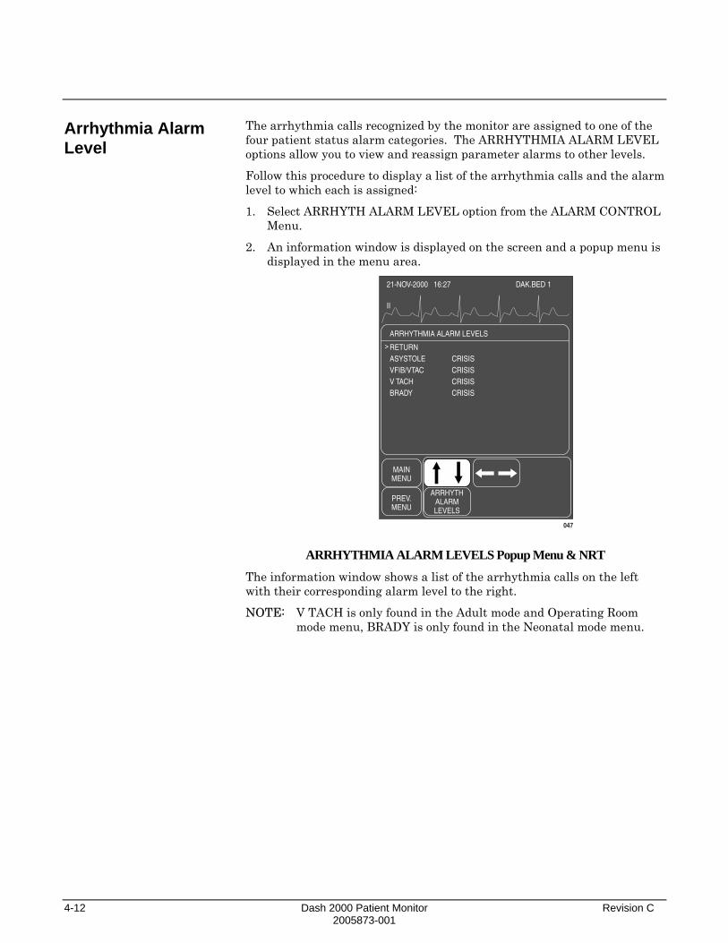
4-12 Dash 2000 Patient Monitor Revision C 2005873-001
Arrhythmia Alarm Level
The arrhythmia calls recognized by the monitor are assigned to one of the four patient status alarm categories. The ARRHYTHMIA ALARM LEVEL options allow you to view and reassign parameter alarms to other levels.
Follow this procedure to display a list of the arrhythmia calls and the alarm level to which each is assigned:
1. Select ARRHYTH ALARM LEVEL option from the ALARM CONTROL Menu.
2. An information window is displayed on the screen and a popup menu is displayed in the menu area.
21-NOV-2000 16:27
II
DAK.BED 1
ARRHYTHMIA ALARM LEVELS
RETURNASYSTOLEVFIB/VTACV TACHBRADY
CRISISCRISISCRISISCRISIS
MAINMENU
ARRHYTHALARMLEVELS
PREV.MENU
>
047
ARRHYTHMIA ALARM LEVELS Popup Menu & NRT
The information window shows a list of the arrhythmia calls on the left with their corresponding alarm level to the right.
NOTE: V TACH is only found in the Adult mode and Operating Room mode menu, BRADY is only found in the Neonatal mode menu.

Revision C Dash 2000 Patient Monitor 4-13 2005873-001
If you want to move a call to another level, follow this procedure. (In this example we will change V TACH from a Crisis level to a Warning level.) Any changes made with this menu option are temporary and will revert to defaults upon discharge.
NOTE: Asystole and ventricular fibrillation (V FIB, VTAC) cannot be moved when in ICU (Adult and Neonatal) Mode.
1. Rotate the Trim Knob control to move the pointer in front of V TACH.
2. Press the Trim Knob control. The level for the V TACH call highlights.
3. Rotate the Trim Knob control until WARNING is displayed.
4. Press the Trim Knob control to complete the change. The information window is reorganized to include V TACH as a WARNING alarm and the change is in effect. The information window remains open for you to make any other changes.
5. When you have completed all changes, move the pointer to RETURN and press the Trim Knob control to close the information window.

4-14 Dash 2000 Patient Monitor Revision C 2005873-001
For your notes

Revision C Dash 2000 Patient Monitor 5-1 2005873-001
5 MONITOR SETUP Monitor Setup Menu........................................................................5-2
Monitor Defaults.........................................................................5-3 Monitor Defaults Menu ..............................................................5-3
Setup Default Arrhythmia Alarm Levels ............................5-4 Setup Default Parameter Alarm Levels...............................5-6 Setup Default Limits .............................................................5-7 Setup Default Display ...........................................................5-8 Setup Default Parameter Priority ........................................5-9 Recall Default ......................................................................5-10
Display Setup Menu .................................................................5-11 Waveform On / Off ...............................................................5-12 Contrast................................................................................5-13 Color ....................................................................................5-14 Backgrnd ..............................................................................5-14 Time and Date .....................................................................5-14 Set Date................................................................................5-15 Set Time ...............................................................................5-15
Graph Setup ..............................................................................5-16 ECG 1, Waveform 2, Waveform 3.......................................5-17 Graph Location ....................................................................5-18 Alarm Graph ........................................................................5-20 Speed ....................................................................................5-20 Timed Graph ........................................................................5-21
Parameters On / Off..................................................................5-22 Software Summary ...................................................................5-23 Service Mode .............................................................................5-24
Patient Monitor Type ..........................................................5-25 Admit Mode..........................................................................5-25
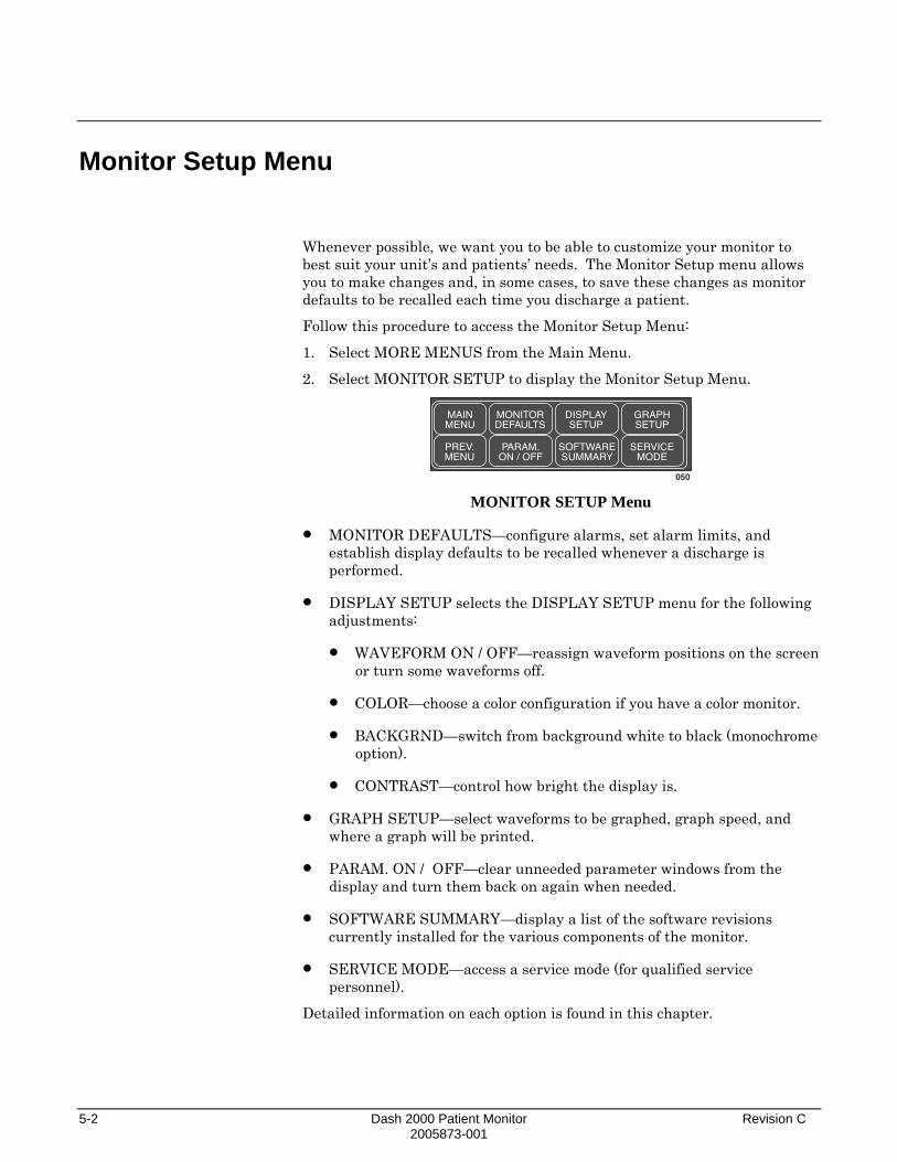
5-2 Dash 2000 Patient Monitor Revision C 2005873-001
Monitor Setup Menu
Whenever possible, we want you to be able to customize your monitor to best suit your unit’s and patients’ needs. The Monitor Setup menu allows you to make changes and, in some cases, to save these changes as monitor defaults to be recalled each time you discharge a patient.
Follow this procedure to access the Monitor Setup Menu:
1. Select MORE MENUS from the Main Menu.
2. Select MONITOR SETUP to display the Monitor Setup Menu.
MAINMENU
MONITORDEFAULTS
DISPLAYSETUP
GRAPHSETUP
PREV.MENU
PARAM.ON / OFF
SOFTWARESUMMARY
SERVICEMODE
050 MONITOR SETUP Menu
• MONITOR DEFAULTS—configure alarms, set alarm limits, and establish display defaults to be recalled whenever a discharge is performed.
• DISPLAY SETUP selects the DISPLAY SETUP menu for the following adjustments:
• WAVEFORM ON / OFF—reassign waveform positions on the screen or turn some waveforms off.
• COLOR—choose a color configuration if you have a color monitor.
• BACKGRND—switch from background white to black (monochrome option).
• CONTRAST—control how bright the display is.
• GRAPH SETUP—select waveforms to be graphed, graph speed, and where a graph will be printed.
• PARAM. ON / OFF—clear unneeded parameter windows from the display and turn them back on again when needed.
• SOFTWARE SUMMARY—display a list of the software revisions currently installed for the various components of the monitor.
• SERVICE MODE—access a service mode (for qualified service personnel).
Detailed information on each option is found in this chapter.

Revision C Dash 2000 Patient Monitor 5-3 2005873-001
Monitor Defaults
Monitor Defaults Menu
Alarm levels, alarm limits, and many of your monitor settings can be set up as Monitor Defaults. Monitor Defaults can only be set when the monitor is in a discharge state. Monitor Defaults are recalled whenever a discharge procedure is performed.
The monitor can save only one set of defaults. Whenever the monitor mode is changed, (Adult-ICU, Neonatal-ICU, Operating Room) any Monitor Defaults you have set up will revert to factory default settings. The monitor mode, however, is usually established at the time of installation and can only be changed in the service menu.
CAUTION If you disconnect a parameter cable at any point along the cable or disconnect it from the module, and the parameter window is removed from the monitor display, all alarm limits may revert to the set monitor default alarm limits when the cable is reconnected.
To display the menu to set up your Monitor Defaults, select MONITOR DEFAULTS from the Monitor Setup Menu.
MAINMENU
SETUPDEFAULTDISPLAY
PARAM.PRIORITY
DEFAULTLIMITS
PREV.MENU
PARAM.ALARMLEVELS
ARRHYTHALARMLEVELS
RECALLDEFAULT
063 MONITOR DEFAULTS Menu
NOTE: Monitor Defaults can only be changed when the monitor is in a discharged state. Changes made are in effect immediately but admit must be done for fully functional alarms.
• SETUP DEFAULT DISPLAY—determine display settings, such as Smart BP on, color format, waveforms graphed, etc.
• PARAM. PRIORITY—determine the priorities you want for display of parameters.
• DEFAULT LIMITS—set alarm limits for all parameters.
• PARAM. ALARM LEVELS—adjust parameter alarm levels to other alarm levels.
• ARRHYTH. ALARM LEVELS—adjust arrhythmia alarms to other alarm levels.
• RECALL DEFAULT—recall Monitor Defaults without performing a discharge procedure.
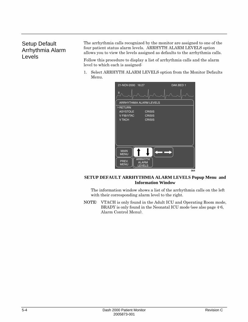
5-4 Dash 2000 Patient Monitor Revision C 2005873-001
Setup Default Arrhythmia Alarm Levels
The arrhythmia calls recognized by the monitor are assigned to one of the four patient status alarm levels. ARRHYTH ALARM LEVELS option allows you to view the levels assigned as defaults to the arrhythmia calls.
Follow this procedure to display a list of arrhythmia calls and the alarm level to which each is assigned:
1. Select ARRHYTH ALARM LEVELS option from the Monitor Defaults Menu.
21-NOV-2000 16:27
II
DAK.BED 1
ARRHYTHMIA ALARM LEVELS
RETURNASYSTOLEV FIB/VTACV TACH
CRISISCRISISCRISIS
MAINMENU
ARRHYTHALARMLEVELS
PREV.MENU
>
064 SETUP DEFAULT ARRHYTHMIA ALARM LEVELS Popup Menu and
Information Window
The information window shows a list of the arrhythmia calls on the left with their corresponding alarm level to the right.
NOTE: VTACH is only found in the Adult ICU and Operating Room mode, BRADY is only found in the Neonatal ICU mode (see also page 4-6, Alarm Control Menu).

Revision C Dash 2000 Patient Monitor 5-5 2005873-001
If you want to move an arrhythmia call to another level for your Monitor Default, follow this procedure. (In this example we will change V TACH from a Crisis to a Warning level.)
NOTE: Asystole and VFIB/VTAC can only be moved when in Operating Room Mode.
1. Rotate the Trim Knob control to move the pointer (>) up and down the list. Stop when the pointer is in front of V TACH.
2. Press the Trim Knob control. Notice that the level for the V TACH call is highlighted.
3. Rotate the Trim Knob control until WARNING is displayed.
4. Press the Trim Knob control to complete the change. The information window is reorganized to include V TACH as a WARNING alarm.
The information window remains open for you to make any other changes.
5. When you have completed all changes, move the pointer to RETURN and press the Trim Knob control to close the information window.

5-6 Dash 2000 Patient Monitor Revision C 2005873-001
Setup Default Parameter Alarm Levels
You can set default alarm levels for all parameters supported by the monitor.
Use the PARAM ALARM LEVELS option to view and adjust default alarm levels for parameters. Follow the same procedure as described for changing arrhythmia alarm level defaults.
21-NOV-2000 16:27
II
DAK.BED 1
PARAMETER ALARM LEVELS
RETURNHRSPO2RRRR-APNEASPO2-RATENBPTP
WARNINGADVISORYADVISORYADVISORYMESSAGEMESSAGEMESSAGE
MAINMENU
PARAM.ALARMLEVELS
PREV.MENU
>
065 PARAM ALARM LEVELS Popup Menu and Information Window
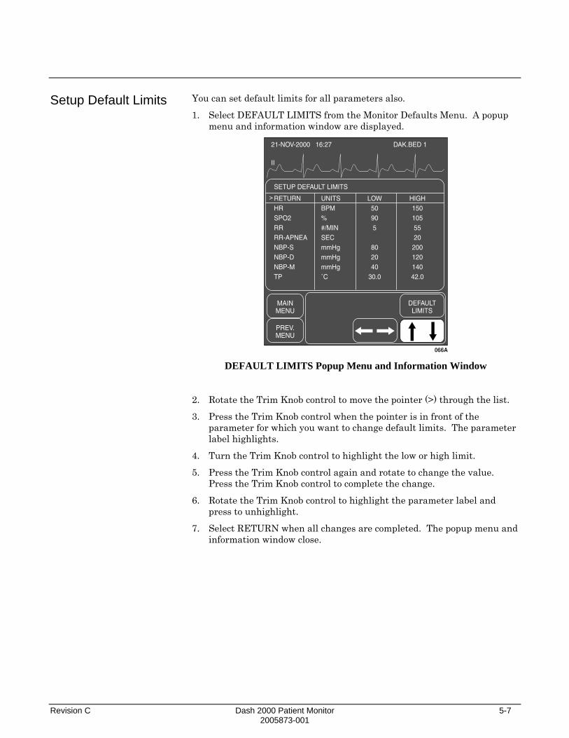
Revision C Dash 2000 Patient Monitor 5-7 2005873-001
Setup Default Limits
You can set default limits for all parameters also.
1. Select DEFAULT LIMITS from the Monitor Defaults Menu. A popup menu and information window are displayed.
21-NOV-2000 16:27
II
DAK.BED 1
SETUP DEFAULT LIMITS
RETURNHRSPO2RRRR-APNEANBP-SNBP-DNBP-MTP
UNITSBPM%#/MINSECmmHgmmHgmmHg˚C
LOW50905
802040
30.0
HIGH1501055520
20012014042.0
MAINMENU
DEFAULTLIMITS
PREV.MENU
>
066A DEFAULT LIMITS Popup Menu and Information Window
2. Rotate the Trim Knob control to move the pointer (>) through the list.
3. Press the Trim Knob control when the pointer is in front of the parameter for which you want to change default limits. The parameter label highlights.
4. Turn the Trim Knob control to highlight the low or high limit.
5. Press the Trim Knob control again and rotate to change the value. Press the Trim Knob control to complete the change.
6. Rotate the Trim Knob control to highlight the parameter label and press to unhighlight.
7. Select RETURN when all changes are completed. The popup menu and information window close.

5-8 Dash 2000 Patient Monitor Revision C 2005873-001
Setup Default Display
This menu option allows you to set up certain aspects of the display as defaults.
1. Select SETUP DEFAULT DISPLAY option from the Monitor Defaults Menu. A popup menu and information window open.
21-NOV-2000 16:27
II
DAK.BED 1
SETUP DISPLAY
RETURNPATIENT AGECOLOR FORMATPRIMARY ECGDETECT PACEARTERIAL RATELEAD ANALYSISGRAPH WAVEFORM 2GRAPH WAVEFORM 3
ADULTTRANSDUCIIOFFOFFSINGLEARTOFF
MAINMENU
SETUPDEFAULTDISPLAY
PREV.MENU
>
067 SETUP DEFAULT DISPLAY Popup Menu and Information Window
2. Using the rotate and press technique with the Trim Knob control, select a display item and make the desired change.
3. Select RETURN when finished to close the popup menu and information window.

Revision C Dash 2000 Patient Monitor 5-9 2005873-001
Setup Default Parameter Priority
This menu option allows you to select how the parameter windows are prioritized on the display.
1. Select PARAM PRIORITY option from the Monitor Defaults Menu. A popup menu and information window open.
21-NOV-2000 16:27
II
DAK.BED 1
DEFAULT PARAMETER PRIORITY
> RETURN PARAMETER 1 PARAMETER 2 PARAMETER 3NBPARTFEMUACPA
ECGSPO2RESP
MAINMENU
PREV.MENU
066
All parameterswhich can bemonitored arelisted (illustrationshown includesBP option).
CVPRAUVCLAICP
SPSPO2RESPTEMP
PARAMPRIORITY
PARAM PRIORITY Popup Menu and Information Window
2. Using the rotate and press technique with the Trim Knob control, select parameters for positions on the display.
The PARAMETER selections in the top half of the window are the ones displayed as full-size windows on the right side of the screen. You control the order of these when you designate a parameter for each position.
The parameters in the lower half of the window will be displayed at the bottom of the screen only when there is no room at the side. You cannot control the order of parameters displayed across the bottom of the screen. The system prioritizes these for you.
See the next page for additional information which may be helpful to you when prioritizing parameters.

5-10 Dash 2000 Patient Monitor Revision C 2005873-001
Recall Default
Here is some additional information regarding parameter priorities:
• The first parameter cannot be changed. It must always be ECG.
• If only four parameters are being monitored then the window will occupy the four positions on the right side of the screen. These windows are always the normal size windows. If monitoring more than four parameters, some will occupy space at the bottom of the screen.
• You can display a maximum of six parameters. The software will not allow you to pick more parameters than can be displayed.
• If you are not monitoring a designated parameter, the space is not left blank, but filled with the next prioritized parameter. Should you begin monitoring the designated parameter, the screen reconfigures so the parameter occupies its designated space.
• Whenever possible waveforms will align with their parameter window. You can override waveform alignment with the WAVEFORMS ON/OFF option.
The RECALL DEFAULT option is a direct action menu option used to recall the monitor defaults while monitoring an admitted patient. In some cases you may have to temporarily override a default. For example, it may be necessary to set different alarm limits for the needs of a specific patient. The alarm limits you set are in effect until you change them again or discharge the patient.
If you have made changes while monitoring a patient and then want to recall the monitor defaults WITHOUT discharging the patient, use the RECALL DEFAULT option.
NOTE: If you are actually changing Monitor Defaults, this option will not recall any prior defaults. If you made changes to defaults that you didn’t want to make you will have to change them manually. Refer to your Defaults Worksheet at the front of this manual, or refer to the Appendix, Factory Defaults, to see the factory defaults.
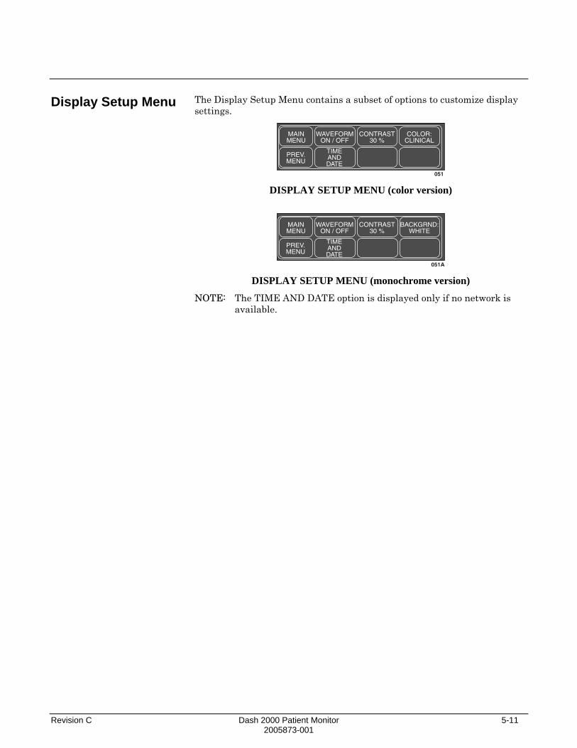
Revision C Dash 2000 Patient Monitor 5-11 2005873-001
Display Setup Menu
The Display Setup Menu contains a subset of options to customize display settings.
MAINMENU
WAVEFORMON / OFF
CONTRAST30 %
COLOR:CLINICAL
PREV.MENU
TIMEANDDATE
051 DISPLAY SETUP MENU (color version)
MAINMENU
WAVEFORMON / OFF
CONTRAST30 %
BACKGRND:WHITE
PREV.MENU
TIMEANDDATE
051A DISPLAY SETUP MENU (monochrome version)
NOTE: The TIME AND DATE option is displayed only if no network is available.
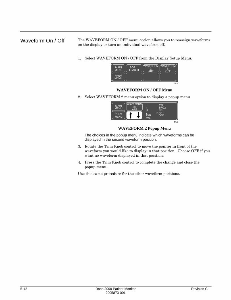
5-12 Dash 2000 Patient Monitor Revision C 2005873-001
Waveform On / Off
The WAVEFORM ON / OFF menu option allows you to reassign waveforms on the display or turn an individual waveform off.
1. Select WAVEFORM ON / OFF from the Display Setup Menu.
MAINMENU
ECG 1:LEAD III
WAVEFORM2:
ART
WAVEFORM3:
OFF
PREV.MENU
052 WAVEFORM ON / OFF Menu
2. Select WAVEFORM 2 menu option to display a popup menu.
MAINMENU
WAVEFORM2:
ART
IIIIIIVAVRAVL
AVFSPO2RRARTOFFPREV.
MENU
>
053 WAVEFORM 2 Popup Menu
The choices in the popup menu indicate which waveforms can be displayed in the second waveform position.
3. Rotate the Trim Knob control to move the pointer in front of the waveform you would like to display in that position. Choose OFF if you want no waveform displayed in that position.
4. Press the Trim Knob control to complete the change and close the popup menu.
Use this same procedure for the other waveform positions.

Revision C Dash 2000 Patient Monitor 5-13 2005873-001
Contrast
This option is used to control the brightness of the monitor’s screen.
1. Select CONTRAST option from the Display Setup Menu. A popup menu is displayed with all choices.
MAINMENU
CONTRAST20 %
100 %90 %80 %70 %60 %
50 %40 %30 %20 %10 %PREV.
MENU
069
20 %
CONTRAST Popup Menu
2. Rotate the Trim Knob control to change the brightness of the display. The change takes place immediately so you can judge the appropriate percentage.
3. Press the Trim Knob control to close the popup menu.

5-14 Dash 2000 Patient Monitor Revision C 2005873-001
Color
(color option) Backgrnd
(monochrome option)
Time and Date
If you have a color monitor, you can use the COLOR menu option to open a popup menu to select a color format.
1. Select COLOR option from the Display Setup Menu. A popup menu is displayed.
MAINMENU
COLOR:CLINICAL
PREV.MENU
054
> CLINICAL TRANSDUC
COLOR Option Popup Menu (COLOR version)
2. Use the Trim Knob control to move the pointer to the color format of your choice:
• CLINICAL—groups physiological functions by color—ECG is amber, hemodynamics are green, and cardiopulmonary and temperature are blue.
• TRANSDUC—matches a color to a specific transducer—ART, FEM, AND UAC are red, PA is yellow, LA and ICP are white, CVP, RA, and UVC are blue, SP and all other physiological parameters are green.
If you have a monochrome monitor, this is a direct action menu option which switches the background from white to black and reverse.
This menu option is displayed only if no network access is detected, and therefore no actual date and time values are available from remote devices.
Select TIME AND DATE to display the TIME AND DATE popup menu.
MAINMENU
SETDATE
SETTIME
PREV.MENU
054A TIME AND DATE Popup Menu

Revision C Dash 2000 Patient Monitor 5-15 2005873-001
Set Date
Set Time
• SET DATE—opens a popup menu to enter or adjust the current date.
MAINMENU
SETDATE
4 F E B 2 0 0 1
PREV.MENU
033 SET DATE Popup Menu
To modify the date, follow this procedure:
1. Rotate the Trim Knob control to select the item you want to adjust; the selected item will be highlighted.
2. Press the Trim Knob control to let the item be changed.
3. Rotate the Trim Knob control until the item shows the desired value; press the Trim Knob control to set the value.
4. Rotate the Trim Knob control to select another item and proceed as in steps 2 and 3 to change the day, month, or year. If an implausible value is entered, the monitor will not accept this value and display a message.
5. To complete the procedure, select the SET DATE option again and press the Trim Knob control.
• SET TIME—opens a popup menu to enter or adjust the current time. The time is displayed in the 24-hour format.
MAINMENU
PREV.MENU
033A
SETDATE 1 1 : 2 9
SETTIME
SET TIME Popup Menu
To modify the time, follow this procedure:
1. Rotate the Trim Knob control to select the item you want to adjust; the selected item will be highlighted.
2. Press the Trim Knob control to let the item be changed.
3. Rotate the Trim Knob control until the item shows the desired value; press the Trim Knob control to set the value.
4. Rotate the Trim Knob control to select another item and proceed as in steps 2 and 3.
5. To complete the procedure, select the SET TIME option again and press the Trim Knob control.

5-16 Dash 2000 Patient Monitor Revision C 2005873-001
Graph Setup
This menu option displays a new menu from which you can change certain aspects of your graphing capabilities.
Select GRAPH SETUP from the Monitor Setup Menu. A new menu is displayed.
MAINMENU
ECG 1:LEAD III
WAVEFORM2:
ART
WAVEFORM3:
OFFALARMGRAPH:ON / OFF
GRAPHTIME /SPEED
PREV.MENU
GRAPHLOCATION
056 GRAPH SETUP Menu
• ECG 1—designate the ECG lead graphed as position 1.
• WAVEFORM 2 (3)—designate the other waveforms to be graphed.
• GRAPH LOCATION—display a new menu to select writers for manual and alarm graphs and information window data.
• ALARM GRAPH—turn automatic alarm graphing on and off.
• GRAPH TIME / SPEED—control the duration of a manual graph and the speed at which a graph is run.
• SPEED—choose a speed at which a graph strip is run.
• TIMED GRAPH—control the duration of a manual graph.
More details on the Graph Setup Menu options follow.

Revision C Dash 2000 Patient Monitor 5-17 2005873-001
ECG 1, Waveform 2, Waveform 3
Each of these options designates a waveform to be printed on the graph strip. You choose the waveforms; the system prioritizes them based on the system priority defaults.
NOTE: The PRN 50 does not reposition the ECG waveform when going from 3 to 2 waveforms during a real time graph run. The graph needs to be stopped and re-started.
Since all of these options are similar, only one, WAVEFORM 2, is detailed below. Use this procedure for the other waveform options.
1. Select WAVEFORM 2 option from the Graph Setup Menu. A popup menu opens displaying all choices. Choices available reflect the parameters currently being monitored.
MAINMENU
WAVEFORM2:
ART
IIIIIIVAVRAVL
AVFSPO2RRARTOFFPREV
MENU
>
057 WAVEFORM 2 Popup Menu
2. Use the Trim Knob control to move the pointer in front of the waveform you want to be graphed.
3. Press the Trim Knob control to confirm the change and close the popup menu.

5-18 Dash 2000 Patient Monitor Revision C 2005873-001
Graph Location
The GRAPH LOCATION option displays a menu which allows you to choose writers for alarm and manual graphs. This menu is shown in the figure below.
MAINMENU
MANUALGRAPH
LOCATION:ICU1CS1
WRITER
ALARMGRAPH:
LOCATION:ICU1CS1
LASER
PRINTWINDOW
LOCATION:ICU1CS1
WRITERPREV.MENU
058 GRAPH LOCATION Menu
• MANUAL GRAPH LOCATION—designate to which writer a graph strip with patient waveforms will be printed. A manual graph is started and stopped with the GRAPH GO / STOP key on the front of the monitor.
• ALARM GRAPH LOCATION—designate to which writer an alarm graph strip with patient waveforms will be printed. An alarm graph is automatically started when a Crisis or Warning alarm occurs.
• PRINT WINDOW LOCATION—designate to which writer the data from an information window will be printed.
You can designate a different writer for each type of graph. Described on the following page is the procedure for selecting a manual graph location. Use the same procedure when selecting an alarm graph location and print window location.
NOTE: The Graph Location Menu is also accessible via the Admit Patient Menu when the Rover or Rover/Combo application is selected.

Revision C Dash 2000 Patient Monitor 5-19 2005873-001
1. Select MANUAL GRAPH LOCATION option from the Graph Location Menu. A popup menu and information window are displayed with a list of writers available on your network.
21-NOV-2000 16:27
II
DAK.BED 1
MANUAL GRAPHLOCATION:
RETURNICUICUICUICUICU
CS 2BED3CS 1BED1BED5
WRITERWRITERWRITERWRITERWRITER
MAINMENU
PREV.MENU
>
MANUALGRAPH
LOCATION:ICU1CS1
WRITER
PRINTWINDOW
LOCATION:ICU1CS1
WRITER
059 MANUAL GRAPH LOCATION Popup Menu and Information
Window
2. Rotate the Trim Knob control so the pointer is in front of the writer you want your manual graphs to go to.
NOTE: The change will not be in effect until the Trim Knob control is pressed and the popup menu closed.
3. Press the Trim Knob control to confirm the change and close the popup menu. The menu option displays the name of the writer where the graph strip will print.
NOTE: Graph locations cannot be set as Monitor Defaults; however, upon discharge, the graph location designations will remain as last selected. If the selected writer/printer is removed from use, this menu option will continue to show that removed device even though it is no longer available. You will have to change it to another available device. The “SAVING” message is displayed when attempting to graph to an unavailable device.
The first column in the list shows the unit where the writer is located. The second column shows the bed number or central station number to which the writer is attached. The third column shows the type of writer—WRITER means it is a Direct Digital Writer, LASER means it is a laser printer.

5-20 Dash 2000 Patient Monitor Revision C 2005873-001
Alarm Graph
Speed
This menu option allows you to turn automatic alarm graphs off and on. This is a direct action menu option. Selecting this option switches back and forth between off and on.
MAINMENU
ECG 1:LEAD III
WAVEFORM2:
ART
WAVEFORM3:
OFFALARMGRAPH:
ON
GRAPHTIME /SPEED
PREV.MENU
GRAPHLOCATION
060 ALARM GRAPH Option
An arrhythmia alarm graph continues to run until a normal sinus rhythm is again detected, or until you manually stop it at the writer. All other alarm graphs will run for 20-seconds.
NOTE: To convert an arrhythmia alarm graph to a manual graph, you must stop the graph using the GRAPH GO / STOP key on the writer and immediately restart the graph.
The speed at which a graph strip is printed is controlled with this menu option. The slower the speed, the more condensed the data will be. This option affects manual graphs only and must be selected before starting the graph.
NOTE: Alarm graphs always run at 25 millimeters per second.
1. Select the GRAPH TIME/SPEED option from the Graph Setup Menu. A menu with the two options SPEED and TIMED GRAPH appears.
2. Select the SPEED option. A popup menu opens displaying all choices.
MAINMENU
SPEED:25 0.1
0.515PREV.
MENU
10 12.5>25 50
061 SPEED Popup Menu
NOTE: A laser printer does not support the 0.1 millimeters per second speed.
3. Rotate the Trim Knob control so the pointer is in front of the speed you want.
4. Press the Trim Knob control to confirm the change and close the popup menu.

Revision C Dash 2000 Patient Monitor 5-21 2005873-001
Timed Graph
The duration at which a manual graph is printed is controlled with this menu option.
1. Select the GRAPH TIME/SPEED option from the Graph Setup Menu. A menu with the two options SPEED and TIMED GRAPH appears.
2. Select the TIMED GRAPH option. A popup menu opens displaying all choices.
MAINMENU
SPEED:25
TIMEDGRAPHCONTIN
10 SEC20 SEC30 SEC60 SECCONTINPREV.
MENU>
062 TIMED GRAPH Popup Menu
3. Rotate the Trim Knob control so the pointer is in front of your choice.
4. Press the Trim Knob control to confirm the change and close the popup menu.
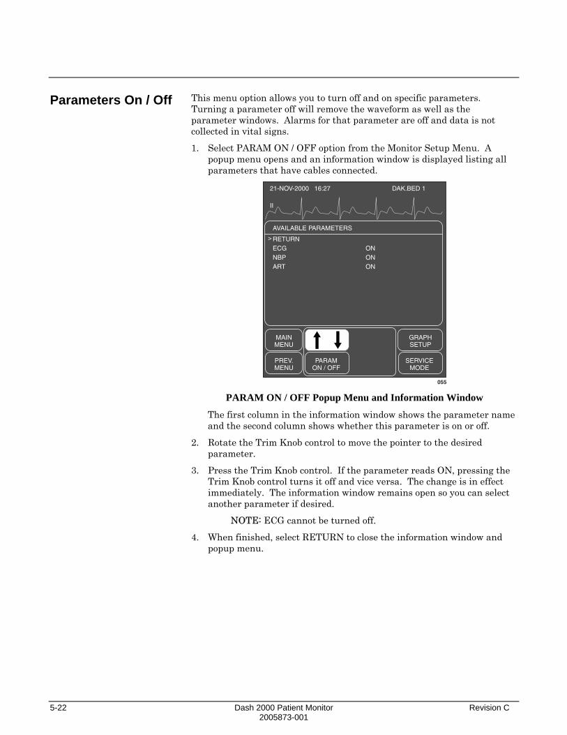
5-22 Dash 2000 Patient Monitor Revision C 2005873-001
Parameters On / Off
This menu option allows you to turn off and on specific parameters. Turning a parameter off will remove the waveform as well as the parameter windows. Alarms for that parameter are off and data is not collected in vital signs.
1. Select PARAM ON / OFF option from the Monitor Setup Menu. A popup menu opens and an information window is displayed listing all parameters that have cables connected.
21-NOV-2000 16:27
II
DAK.BED 1
AVAILABLE PARAMETERS
RETURNECGNBPART
ONONON
MAINMENU
GRAPHSETUP
PREV.MENU
PARAMON / OFF
SERVICEMODE
>
055 PARAM ON / OFF Popup Menu and Information Window
The first column in the information window shows the parameter name and the second column shows whether this parameter is on or off.
2. Rotate the Trim Knob control to move the pointer to the desired parameter.
3. Press the Trim Knob control. If the parameter reads ON, pressing the Trim Knob control turns it off and vice versa. The change is in effect immediately. The information window remains open so you can select another parameter if desired.
NOTE: ECG cannot be turned off.
4. When finished, select RETURN to close the information window and popup menu.

Revision C Dash 2000 Patient Monitor 5-23 2005873-001
Software Summary
It is important to know how to find out what software revisions (versions) your system is using. Follow this procedure.
1. Select SOFTWARE SUMMARY option from the Monitor Setup Menu. A popup menu and information window are displayed.
21-NOV-2000 16:27
II
DAK.BED 1
SOFTWARE SUMMARY
SOFTWARE REVISIONS:MAINMAIN BOOTDASDAS BOOTDDW
ADMIT MENU:MONITOR TYPE:
3AX012ATST4A2BX01VER 2ASTANDARDADLT-ICU
MAINMENU
MONITORDEFAULTS
PREV.MENU
SOFTWARESUMMARY
OKPARAM.
ON / OFF
>
070
(C) COPYRIGHT 2000 - 2001GE MEDICAL SYSTEMSINFORMATION TECHNOLOGIES GMBH
SOFTWARE SUMMARY Popup Menu and Information Window
The information in the list is most useful to service personnel.
2. Select OK to close the popup menu and information window.

5-24 Dash 2000 Patient Monitor Revision C 2005873-001
Service Mode
The service menu is meant for qualified service personnel and, therefore, is password protected. If you select SERVICE MODE option from the Monitor Setup Menu you will see a screen similar to the one shown below.
21-NOV-2000 16:27
II
DAK.BED 1
CAUTION !!
YOU ARE ABOUT TO ENTER THESERVICE MODE OF OPERATION.
IF YOU PROCEED, YOU MAY LOSEYOUR MONITOR CONFIGURATION.
SOME OPERATIONS WILL CAUSEA COLD START OF THE MONITOR.
ENTER THE PASSWORD ANDPROCEED AT YOUR OWN RISK!
MAINMENU
PREV.MENU
SERVICEMODE
O O O O
071 SERVICE MODE Popup Menu and Information Window
When the password is entered and the popup menu closed, the Service Mode Menu will be displayed.
MAINMENU
BATTERYSERVICE
REVIEWERRORSCALIBRATE ADDRESS
MONITOR /ADMITTYPE
TIMEANDDATE
072 SERVICE MODE Menu
The service mode is used by qualified field engineers, factory service personnel, and hospital biomedical engineers to set up, troubleshoot, and repair the monitor. If you want more details please refer to the appropriate product service manual.

Revision C Dash 2000 Patient Monitor 5-25 2005873-001
Patient Monitor Type
Admit Mode
Following is an explanation of two Service Menu options which have been mentioned in other places in the manual.
In many places throughout the manual the patient-monitor type is mentioned. Your monitor is set up for monitoring in one of three modes with the PATIENT-MONITOR TYPE option:
Adult-ICU (ADLT-ICU), Neonatal-ICU (NEO-ICU), or Operating Room (OP-ROOM).
You will know which mode your monitor is set up for by the absence or presence of a label on the date and time line at the top of the display. Adult-ICU has no label. The other labels are NEO-ICU and OP-ROOM. The patient must be DISCHARGED to change the patient monitor type.
Remember, when you change the patient-monitor type any Monitor Defaults you have set will be lost and factory defaults will again be in effect.
Another option in the Service Menu which affects your monitor is the ADMIT MODE. The admit mode determines the menu options you will use when admitting a patient to the monitor. The admit modes are:
Standard, Rover, Combo, and Rover Combo (ROV COM).

5-26 Dash 2000 Patient Monitor Revision C 2005873-001
For your notes

Revision C Dash 2000 Patient Monitor 6-1 2005873-001
6 PATIENT DATA Patient Data Menu ..........................................................................6-2
Vital Signs ...................................................................................6-3 View Older / View Newer ......................................................6-4 Time Interval .........................................................................6-4 Specific Time ..........................................................................6-4 Page Down and Page Up .......................................................6-4
Graphic Trends ...........................................................................6-5 Select Parameters..................................................................6-6 View Older / View Newer ......................................................6-7 Time Period ............................................................................6-7

6-2 Dash 2000 Patient Monitor Revision C 2005873-001
Patient Data Menu
Select PATIENT DATA from the Main Menu to display the following menu:
MAINMENU
GRAPHICTRENDS
VITALSIGNS
PREV.MENU
073 PATIENT DATA Menu
• VITAL SIGNS (TABULAR TRENDS)—display the values for the patient’s monitored parameters over the last 24 hours.
• GRAPHIC TRENDS—plot trends for selected parameters.
Detailed information on each option is found in this chapter.

Revision C Dash 2000 Patient Monitor 6-3 2005873-001
Vital Signs
NOTE: Vital Signs is called TABULAR TRENDS if your monitor is in the Operating Room mode.
Upon admit to the system, a history of the patient’s vital signs is continually being collected. Follow this procedure to display this patient data:
1. Select VITAL SIGNS (TABULAR TRENDS) from the Patient Data Menu. An information window and new set of menu options are displayed.
21-APR-2001 17:10
II
DAK.BED 1
MAINMENU
PREV.MENU
SPECIFICTIME
PAGEUP
PAGEDOWN
VIEWOLDER
VIEWNEWER
TIMEINTERVAL:
15 MINS
VITAL SIGNS 21-APR-2001 17:10
RETURN
SPO2-%SPO2-RRNBP-SNBP-DNBP-M
ALARMS
21-APR16:15
6899
21-APR16:30
6899
21-APR16:45
6798
OFF
21-APR17:00
6799
1327092
OFF
> HR
074
Current Date and Time
OFF is displayed if alarmswere paused or the monitorwas in discharged state.
Press the GRAPH GO/STOPkey to print the vital signsinformation.
VITAL SIGNS Menu and Information Window
For most parameters, 24 hours of data is collected. For NBP 96 values (NBP-S, NBP-D, NBP-M) are collected. With a BP interval of 15 minutes, 24 hours of NBP data is collected.
2. You cannot change any values in the Vital Signs but you can use the menu options to move through all the data collected. Refer to the following page for details.

6-4 Dash 2000 Patient Monitor Revision C 2005873-001
View Older / View Newer
Time Interval
Specific Time
Page Down and Page Up
Described below are the Vital Signs Menu options.
Each of these direct action menu options will move the data displayed either backward or forward in time if data is available.
Select TIME INTERVAL to choose the time interval between each of the displayed columns of data. This does not affect data collection, only how it is displayed.
MAINMENU
VIEWOLDER
TIMEINTERVAL:
15 MINS
1 HR30 MINS15 MINS5 MINS1 MINPREV.
MENUPAGEDOWN
>
075 TIME INTERVAL Popup Menu
1. Rotate the Trim Knob control to move the pointer in front of the time interval of choice.
2. Press the Trim Knob control to close the popup menu and effect the change.
Select SPECIFIC TIME option to open a popup menu which allows you to enter a specific time you want to find and display in vital signs.
MAINMENU
SPECIFICTIME
PREV.MENU 27 NOV 2000 16:27
076 SPECIFIC TIME Popup Menu
1. Rotate the Trim Knob control to move the highlight into the date and time. (The popup menu opens with the current date and time.)
2. Press the Trim Knob control when an element in the date or time is highlighted. Rotate to make a change.
3. Press the Trim Knob control to complete the change, and rotate to highlight the next element in the date and time.
4. Close the popup menu by rotating the Trim Knob control to highlight SPECIFIC TIME, then press the Trim Knob control. The specific time you requested (or the time closest to it if your TIME INTERVAL is set for other than one minute) will appear in the middle column of the information window.
These direct action menu options work just like VIEW OLDER and VIEW NEWER but instead of moving the data in time, they display any additional data not displayed on the screen due to space restrictions.

Revision C Dash 2000 Patient Monitor 6-5 2005873-001
Graphic Trends
Another way of displaying collected patient data is through trends. A trend is a graphic representation of one parameter over a specified period of time. Every non-episodic parameter is sampled 30 times a minute. A median value is determined and that value is stored for trend display at one-minute resolution. Episodic parameters (NBP, etc.) are stored every time one occurs.
Follow this procedure to view graphic trends:
1. Select GRAPHIC TRENDS from the Patient Data Menu. An information window and new set of menu options are displayed.
HR
GRAPHIC TRENDS 27-NOV-1998 16:27
150
50
SPO2-%
100
90
MAINMENU
VIEWOLDER
VIEWNEWER
PREV.MENU
SELECTPARAM.
TIMEPERIOD:90 MINS
077
The trend data willautomatically update whiledisplayed. Refer to this chapter, Time Period.Press the GRAPH GO/STOPkey to print the displayedtrends.
GRAPHIC TRENDS Menu and Information Window
The graphic trends for the last selected parameters are displayed. Heart rate is the default if none were previously selected.
2. To select other parameters for trending follow the procedure on the following page.
NOTE: All trend data that is available at the monitor can be requested by a network device viewing trends, e.g., central station.

6-6 Dash 2000 Patient Monitor Revision C 2005873-001
Select Parameters
1. Select the SELECT PARAMETERS option from the Graphic Trends Menu. A popup menu and the Vital Signs information window are displayed.
27-APR-2001 17:10
II
DAK.BED 1
MAINMENU
PREVMENU
SELECTPARAM.
VIEWOLDER
MARKPARAM
VITAL SIGNS 27-APR-2001 17:10
SPO2-%SPO2-RNBP-SNBP-DNBP-M
ALARMS
27-APR16:15
6899
27-APR16:30
6899
27-APR16:45
6798
OFF
27-APR17:10
6799
1327092
OFF
> HR
078
Notice the pointer (>)and a RETURN optionin this window.
SELECT PARAMETERS Popup Menu
2. To mark (highlight) a parameter for trending, rotate the Trim Knob control to move the pointer and then press the Trim Knob control. In this example HR is highlighted because that is the default. Up to two parameters can be selected. Selecting a third will unmark the first selection chosen.
NOTE: NBP or an invasive pressure with a systolic, diastolic, and mean value is considered one selection. For example, if you select ART-S, the other two parameters (ART-D and ART-M) will also highlight. However, the trends for these parameters will appear in only one trend window. If you only want to plot one of the three pressure parameters, simply unmark those you don’t want.
3. When the parameters you want to plot as trends are highlighted, move the pointer to RETURN and press the Trim Knob control. The popup menu closes and the information window reconfigures to display the trends.

Revision C Dash 2000 Patient Monitor 6-7 2005873-001
View Older / View Newer
Time Period
Use these options to move backward and forward in time.
NOTE: These options do not function when viewing in the 6-minute time period.
Use this option to open a popup menu to select a time period for viewing the displayed trends.
MAINMENU
TIMEPERIOD90 MINS
24 HRS12 HRS6 HRS3 HRS90 MINS
60 MINS30 MINS15 MINS6 MINSPREV.
MENU
>
079 TIME PERIOD Popup Menu
Displayed trends will automatically update. The frequency of the update is based on the time period selected.
6 MINS updates every 10 seconds (not for NBP) 15, 30 MINS updates every minute 60 MINS, 90 MINS, 3 HRS updates every minute 6 HR updates every 2 minutes 12 HRS updates every 4 minutes 24 HRS updates every 8 minutes

6-8 Dash 2000 Patient Monitor Revision C 2005873-001
For your notes

Revision C Dash 2000 Patient Monitor 7-1 2005873-001
7 MAINTENANCE Biocompatibility ...............................................................................7-2
Inspection .........................................................................................7-3
General Cleaning .............................................................................7-4 Exterior Surface..........................................................................7-4 Display.........................................................................................7-5
Cleaning Applied Parts ...................................................................7-6 Cables and Leadwires.................................................................7-6 Other............................................................................................7-6
Technical Maintenance....................................................................7-7 Technical Inspections .................................................................7-7
Changing Graph Paper....................................................................7-8 Built-in Writer ............................................................................7-8
Thermal Paper Storage ...................................................................7-9

7-2 Dash 2000 Patient Monitor Revision C 2005873-001
Biocompatibility
When used as intended, the parts of the product described in this operator manual, including accessories that come in contact with the patient during the intended use, fulfill the biocompatibility requirements of the applicable standards. If you have questions in this matter, please contact GE Medical Systems Information Technologies or its representatives.

Revision C Dash 2000 Patient Monitor 7-3 2005873-001
Inspection
An effective maintenance schedule should be established for your monitoring equipment and reusable supplies. This should include inspection as well as general cleaning on a regular basis. The maintenance schedule must comply with the policies of your institution’s infection control unit and/or biomed department.
WARNING Failure on the part of the responsible hospital or institution employing the use of this monitoring equipment to implement a satisfactory maintenance schedule may cause undue equipment failure and possible health hazards.
Check with your Biomedical Department to be sure preventive maintenance and calibration has been done. The service manuals contain detailed information. Follow these guidelines when inspecting the equipment:
• Inspect the equipment for obvious physical damage and replace damaged items.
• Inspect all cords for fraying or other damage. Inspect all plugs and connectors for bent prongs or pins. Repair or replacement must be performed by qualified service personnel.
• Inspect all cable insulation. Qualified service personnel should repair or replace damaged or deteriorated cables.
In the United States, GE Medical Systems Information Technologies Service is available 24-hours a day by calling 800-558-7044. Outside the United States, please contact your sales/service office.
NOTE: Refer to the service manuals for more comprehensive checkout procedures.
Check before each use
Before each use visually check the monitor, the cables and the sensors for signs of mechanical damage.
Check all functions relevant to patient monitoring
Should you detect damages or impaired monitor functions which present a hazard to the patient or the user, have the monitor inspected and repaired before using it again.
Furthermore the alarm system (audio alarms, alarm indicators) must be checked.

7-4 Dash 2000 Patient Monitor Revision C 2005873-001
General Cleaning
Exterior Surface
WARNING Disconnect the monitor from the power line before cleaning or disinfecting its surface.
The equipment should be cleaned on a regular basis. (Comply with the policies of your institution’s infection control unit and/or biomed department.) The exterior surfaces of the equipment may be cleaned with a dampened, lint-free cloth. Use one of the following approved solutions:
• ammonia (diluted),
• Cidex,
• sodium hypochlorite bleach (diluted), or
• mild soap (diluted). To avoid damage to the equipment, follow these rules:
CAUTION Failure to follow these rules may melt, distort, or dull the finish of the case, blur lettering on the labels, or cause equipment failures.
• Always dilute the solutions according to the manufacturer’s suggestions.
• Always wipe off all the cleaning solution with a dry cloth after cleaning.
• Never use a cleaning substance containing wax.
• Never pour or spray water or any cleaning solution on the equipment or permit fluids to run behind switches, into the connectors, or into any ventilation openings in the equipment.
• Never use these cleaning agents:
abrasive cleaners or solvents of any kind,
acetone
ketone,
alcohol based cleaning agents, or
Betadine.
Revision C Dash 2000 Patient Monitor 7-5 2005873-001
Display To clean the display screen, use a soft, clean cloth dampened with a glass cleaner. Never spray the glass cleaner directly onto the display, and never use alcohol or hospital disinfectants like Betadine.
The Dash monitors have a special filter for the display. Specifically, it’s a circular-polarized filter with an anti-reflective coating. This type of filter increases the display’s contrast while it reduces glare from nearby lights.
If you look closely at the display while it’s turned off, you might notice milky-white streaks. The streaks don’t mean that you need to clean the display. They’re caused by the circular polarization effect of the filter, and they are perfectly normal with this type of filter.

7-6 Dash 2000 Patient Monitor Revision C 2005873-001
Cleaning Applied Parts
Cables and Leadwires
Other
CAUTION Do not use acetone or ketone solvents for cleaning; do not use an autoclave or steam cleaner.
Cables and leadwires can be cleaned with a warm, damp cloth and mild soap, or isopropyl alcohol wipes. Refer to page 7-4 for safe cleaning techniques.
For more intensive disinfecting (near sterile) Ethylene Oxide (ETO) is acceptable but will reduce the useful lifetime of the cable or leadwire.
CAUTION The decision to sterilize must be made per your institution’s requirements with an awareness of the effect on the integrity of the cable or leadwire.
For other applied parts such as temperature sensors, catheters, pulse oximetry probes, and NBP cuffs, refer to the documentation supplied with these parts for cleaning, sterilization, or disinfecting methods.

Revision C Dash 2000 Patient Monitor 7-7 2005873-001
Technical Maintenance
Technical Inspections
Schematic diagrams, specifications, and other relevant technical information can be found in the service manuals. Comply with the policies of your institution’s biomed department, or the recommendations made within the Preventive Maintenance section of the product’s service manual.
For safety, the devices require regular maintenance. To ensure functional and operational safety of the Dash 2000 patient monitor, technical inspections should be carried out on an annual basis.
These inspections should be referred to independent persons with adequate training and experience.
Within the framework of a service agreement, GE Medical Systems Information Technologies service representatives would be pleased to carry out these technical inspections for you.
The relevant sections of the Field Service Manual describe the scope and nature of the technical inspections.
The Dash 2000 patient monitor does not require other regular maintenance checks.

7-8 Dash 2000 Patient Monitor Revision C 2005873-001
Changing Graph Paper
Built-in Writer
1. Open the door by pressing on the top of the writer, as indicated below.
638A
2. Remove the old paper spool and install a new paper roll. (The paper
contains a special coating on one side and must be installed correctly.) Install the paper so it unrolls from the bottom.
639A
3. Close the door. Make sure the paper protrudes through the opening.
640A
4. Test the writer by initiating a graph strip (refer to The Basics chapter,
Graphing (Printing) for directions). Be sure to tear downward when removing a graph strip from the writer.
NOTE: If the graph strip is blank, the paper is probably installed upside-down. Turn the spool over so the paper unwinds from the other direction.

Revision C Dash 2000 Patient Monitor 7-9 2005873-001
Thermal Paper Storage
To avoid deterioration or fading of traces, follow these precautions:
NOTE: These precautions apply to both unused paper as well as paper that has already been run through the writer.
Store in cool, dark locations. Temperature must be below 80°F (27°C). Relative humidity must be between 40% and 65%.
Avoid exposure to bright light or ultraviolet sources such as sunlight, fluorescent, and similar lighting which causes yellowing of paper and fading of tracings.
DO NOT STORE THERMAL PAPER WITH ANY OF THE FOLLOWING:
• carbon and carbonless forms.
• non-thermal chart papers or any other products containing tributyl phosphate, dibutyl phthalate, or any other organic solvents. Many medical and industrial charts contain these chemicals.
• document protectors, envelopes, and sheet separators containing polyvinyl chloride or other vinyl chlorides.
AVOID CONTACT WITH: cleaning fluids and solvents such as alcohols, ketones, esters, ether, etc.
DO NOT USE: mounting forms, pressure-sensitive tapes or labels containing solvent-based adhesives.
To assure MAXIMUM TRACE IMAGE LIFE, thermal paper should be stored separately in: manilla folders, polyester or polyimide protectors.
Plastic document protectors, envelopes, or sheet separators made of polystyrene, polypropylene, or polyethylene will not degrade thermal traces in themselves. However, these materials afford no protection against fading from external causes.
Use only mounting forms and pressure-sensitive tapes made with starch or water-based adhesives.
Paper manufacturers advise us that these thermal products should retain their traces when properly imaged and stored for about 3-5 years. If your retention requirements exceed these guidelines, we recommend you consider alternate image storage techniques.

7-10 Dash 2000 Patient Monitor Revision C 2005873-001
For your notes

Revision C Dash 2000 Patient Monitor 8-1 2005873-001
8 ECG Introduction......................................................................................8-2
Checklist......................................................................................8-2
Skin Preparation..............................................................................8-3
Electrode Placement ........................................................................8-4 5-Leadwire Electrode Placement ...............................................8-4 3-Leadwire Electrode Placement ...............................................8-5
Three-leadwire Configuration ..............................................8-5 Electrode Placement for Neonates.............................................8-6 Electrode Placement for Pacemaker Patients ..........................8-7 Maintaining Quality ECG Signal ..............................................8-8 Surgical Considerations for Electrode Placement (Adults) .....8-8
ESU ECG Filters..............................................................................8-8 Electrosurgical Unit (ESU Cable) .............................................8-8
ECG Monitoring Features...............................................................8-9 ECG Display................................................................................8-9 Getting to the ECG Menu ........................................................8-10
ECG Menu Options........................................................................8-11 Display Lead .............................................................................8-11
Synchronized Cardioversion ...............................................8-11 Smart-Lead Fail...................................................................8-12 Leads Fail Patient Condition..............................................8-12
ECG Size....................................................................................8-13 ECG Limits................................................................................8-14
Heart Rate............................................................................8-14 Relearn ......................................................................................8-15 QRS Volume ..............................................................................8-15 Analysis Settings ......................................................................8-16
ECG Filter............................................................................8-17 Lead Analysis.......................................................................8-18 Multi-Lead Analysis ............................................................8-18 Single Lead Analysis ...........................................................8-18 Changing Lead Analysis .....................................................8-18 Detect Pace...........................................................................8-19 Safety Considerations .........................................................8-19 Monitoring Internal Pacemaker Patients ..........................8-20 Monitoring Dash Responder Paced Patient.......................8-21 QRS Width ...........................................................................8-22 Changing QRS Width ..........................................................8-22 Arrhythmia ..........................................................................8-23 Lethal ...................................................................................8-23 Arrhythmia Conditions .......................................................8-23
Troubleshooting .............................................................................8-25
Internal Pacemaker Troubleshooting...........................................8-26

8-2 Dash 2000 Patient Monitor Revision C 2005873-001
Introduction
Checklist
The information in this chapter will help you to successfully use all the ECG monitoring features of your Dash monitor. The ECG connector where the patient cable is plugged into the monitor is shown below.
ECG Connector080
BP
ECG Temp
SPO2
NBP
Dash 2000 Monitor—ECG Connector
NOTE: The signal input is a high-insulation port and it is defibrillator-proof ( ).
The insulated input ensures patient safety and protects the device during defibrillation and electrosurgery.
Use only the electrodes listed in the enclosed publication "Accessories – Dash 2000/3000". Electrodes for diagnostic use may vastly compromize recovery time and stability after defibrillation.
Do not connect any electrode to metal parts or ground.
1. Electrodes have been placed on the patient following proper skin preparation.
NOTE: When using “snap” leadwires, attach leadwires to electrodes first, then apply electrodes to the patient. This prevents the gel from spreading and becoming ineffective as you attach the snaps to the electrodes.
2. Leadwires are attached to electrodes on the patient.
3. Leadwires are connected to patient cable and patient cable is connected to the monitor.
4. Verify the V-lead label is correct if using a 5-leadwire patient cable.
5. ECG setup is adjusted, if necessary. Follow detailed procedures within this chapter.

Revision C Dash 2000 Patient Monitor 8-3 2005873-001
Skin Preparation
The quality of ECG information displayed on the monitor is a direct result of the quality of the electrical signal received at the electrode.
Proper skin preparation is necessary for good signal quality at the electrode. A good signal at the electrode provides the monitor with valid information for processing the ECG data.
Choose flat, non-muscular areas to place electrodes, then follow the established prep protocol for your unit. Following is a suggested guideline for skin preparation:
1. Shave hair from skin at chosen sites.
2. Gently rub skin surface at sites to remove dead skin cells.
3. Thoroughly clean the site with alcohol or a mild soap and water solution. Be sure to remove all oily residue, dead skin cells, and abrasives. Leftover abrasion particles can be a source of noise.
4. Dry the skin completely before applying the electrodes.

8-4 Dash 2000 Patient Monitor Revision C 2005873-001
Electrode Placement
5-Leadwire Electrode Placement
The chart below shows the label used to identify each leadwire. Included also is its associated color code per AHA and IEC standards.
Leadwire (Software Label)
AHA Color
AHA Label
IEC Color
IEC Label
RA (right arm) white RA red R
LA (left arm) black LA yellow L
RL (right leg) green RL black N
LL (left leg) red LL green F
V1 (precordial) brown V1 white C1
V2 (precordial) yellow V2 yellow C2
V3 (precordial) green V3 green C3
V4 (precordial) blue V4 brown C4
V5 (precordial) orange V5 black C5
V6 (precordial) purple V6 purple C6
Following is a suggested configuration when using five leadwires:
132B
V1
RA LA
RL LL 132C
C1
R L
N F
AHA Configuration IEC Configuration
Right arm and left arm electrodes should be placed just below the right and left clavicle.
Right leg and left leg electrodes should be placed on a non-muscular surface on the lower edge of the rib cage.
The chest electrode should be placed according to the physician’s preference.

Revision C Dash 2000 Patient Monitor 8-5 2005873-001
3-Leadwire Electrode Placement
When a 5-leadwire electrode configuration is not desirable, a 3-leadwire electrode configuration can be used.
348A
RA LA
LL 348B
R L
F
AHA Configuration IEC Configuration
Three-leadwire Configuration
NOTE: Electrode configuration will vary depending on the type of leadwire set you are using. Refer to ”Three-leadwire Configuration” below.
Right arm and left arm electrodes should be placed just below the right and left clavicle.
Left leg electrode should be placed on a non-muscular surface on the lower edge of the rib cage.
The molded 3-leadwire sets can be placed in the 5-lead Multi-Link patient cable.
Standard Molded 3-leadwire Set (Rotating Reference)
• Selectable lead I, II, or III cable with a rotating reference (right arm, left arm, left leg).
Operation of the monitor with this standard cable allows you to select one of three leads (I, II, or III) for monitoring.
When using the standard, 3-leadwire configuration, the following operating conditions occur:
• LD ANALYSIS automatically switches to single lead analysis. If an attempt is made to change to multi-lead analysis, a message "NOT POSSIBLE WITH 3 LEAD CABLE" will appear briefly and no change will occur.
• DISPLAY LEAD choices are limited to I, II, and III.
• Any options usually allowing more than one ECG lead selection will be disallowed. A message line is displayed briefly, indicating such.

8-6 Dash 2000 Patient Monitor Revision C 2005873-001
Electrode Placement for Neonates
• Respiration can be monitored from either lead I or II. It is not dependent on the displayed lead.
WARNING Route cables away from patient’s throat to avoid possible strangulation.
Because of the size of neonatal patients, there is usually only enough room for a 3-leadwire electrode configuration. A 3-lead neonatal ECG cable is available, and a Multi-Link DIN adapter is available for the 5-lead Multi-Link cable. The right arm and left arm or right arm and left leg electrodes are positioned on the right and left sides of the chest. The third electrode (right leg) can be placed on either the right or left side of the abdomen.
RALL
RL
RA LA
RL
R L
N
RF
N
Lead II Lead I
AHA Configuration
Lead II Lead I
IEC Configuration081
NOTE: Use the neonatal patient cable!

Revision C Dash 2000 Patient Monitor 8-7 2005873-001
Electrode Placement for Pacemaker Patients
Electrodes need to be repositioned to modify detection of the electrical signals generated by the pacemaker. Following is a suggested configuration:
NOTE: When using this configuration, display Lead II as your primary ECG lead.
AHA Configuration IEC Configuration
The right arm electrode is moved down to the 5th intercostal space, and the left leg electrode is moved up to the 5th intercostal space.
NOTE: After all electrodes are in place, ensure minimum of 1/2 mV of signal is present on each lead (I, II, III, V).

8-8 Dash 2000 Patient Monitor Revision C 2005873-001
Maintaining Quality ECG Signal Surgical Considerations for Electrode Placement (Adults)
ESU ECG Filters
Electrosurgical Unit (ESU Cable)
Regardless of patient age, electrodes should be replaced at least every 48 hours to maintain quality signals during long-term monitoring. Over the course of 48 hours, the electrode gel will start to dry out and the adhesive will age. After a long period of time, the patient’s sensitive skin also may be irritated by the gel or adhesive causing discomfort. Stabilize the electrode and leadwire with a leadwire stress loop near the electrode. Tape the stress loop to the patient. A secured stress loop prevents leadwire rotation about the electrode snap, leadwire tugging at the electrode, and ECG artifact.
Thorough skin preparation is very important to help keep ESU interference to a minimum. Do a thorough skin prep to the skin next to the grounding pad as well.
Place the right leg electrode close to the ESU grounding pad.
The Multi-Link ESU ECG patient cable is recommended when using the monitor in the presence of an electrosurgical unit. This cable, with a built-in ESU filter, helps reduce electrosurgical noise detected on the ECG signal.
082
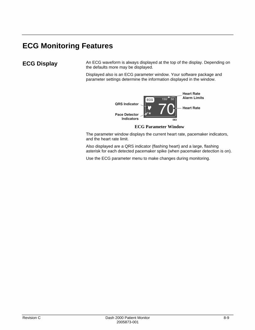
Revision C Dash 2000 Patient Monitor 8-9 2005873-001
ECG Monitoring Features
ECG Display
An ECG waveform is always displayed at the top of the display. Depending on the defaults more may be displayed.
Displayed also is an ECG parameter window. Your software package and parameter settings determine the information displayed in the window.
ECG 150/ 50
P* 70083
Heart RateAlarm Limits
QRS Indicator
Pace DetectorIndicators
Heart Rate
ECG Parameter Window
The parameter window displays the current heart rate, pacemaker indicators, and the heart rate limit.
Also displayed are a QRS indicator (flashing heart) and a large, flashing asterisk for each detected pacemaker spike (when pacemaker detection is on).
Use the ECG parameter menu to make changes during monitoring.

8-10 Dash 2000 Patient Monitor Revision C 2005873-001
Getting to the ECG Menu
To display the ECG Menu, use the Trim Knob control to select the ECG parameter label. Remember, selecting with the Trim Knob control is a two-step process—rotate to highlight, then press to select.
ECG 150/ 50
P* 60084
Selecting the ECG Parameter Label The ECG Menu is displayed at the bottom of the screen.
MAINMENU
ECGSIZE:
1XDISPLAYLEAD II
ECGLIMITS
RELEARN ANALYSISSETTINGS
QRSVOLUME:
OFF
085 ECG Menu
With the Trim Knob control, you can now select any of the displayed options.
• DISPLAY LEAD—change the top displayed (primary) ECG lead.
• ECG SIZE—change the size of all ECG waveforms displayed and graphed.
• ECG LIMITS—display a new menu and an information window to adjust heart rate alarm limits.
• RELEARN—relearn the patient’s QRS pattern to enable more accurate monitoring.
• QRS VOLUME—turn the QRS tone on/off, and adjust volume when on.
• ANALYSIS SETTINGS—displays a new menu to adjust single or multi-lead analysis, pace detection, and filter settings.
Detailed information on each option is found in this chapter.
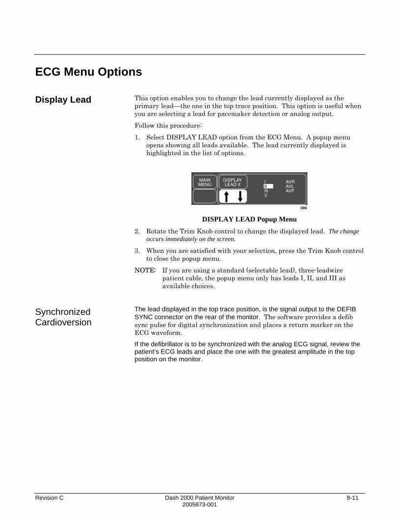
Revision C Dash 2000 Patient Monitor 8-11 2005873-001
ECG Menu Options
Display Lead
Synchronized Cardioversion
This option enables you to change the lead currently displayed as the primary lead—the one in the top trace position. This option is useful when you are selecting a lead for pacemaker detection or analog output.
Follow this procedure:
1. Select DISPLAY LEAD option from the ECG Menu. A popup menu opens showing all leads available. The lead currently displayed is highlighted in the list of options.
MAINMENU
DISPLAYLEAD II
AVRAVLAVF
086
IIIIIIV
DISPLAY LEAD Popup Menu
2. Rotate the Trim Knob control to change the displayed lead. The change occurs immediately on the screen.
3. When you are satisfied with your selection, press the Trim Knob control to close the popup menu.
NOTE: If you are using a standard (selectable lead), three-leadwire patient cable, the popup menu only has leads I, II, and III as available choices.
The lead displayed in the top trace position, is the signal output to the DEFIB SYNC connector on the rear of the monitor. The software provides a defib sync pulse for digital synchronization and places a return marker on the ECG waveform. If the defibrillator is to be synchronized with the analog ECG signal, review the patient’s ECG leads and place the one with the greatest amplitude in the top position on the monitor.

8-12 Dash 2000 Patient Monitor Revision C 2005873-001
Smart-Lead Fail
Leads Fail Patient Condition
NOTE: The smart-lead fail feature works only when using a 5-leadwire electrode configuration.
The smart-lead fail feature is continually checking the integrity of the electrodes to allow uninterrupted monitoring. Should the quality of an electrode signal degrade to an inadequate level, a lead fail message will be displayed. If the lead fail affects the ECG waveform monitored in the top trace position on the screen, monitoring will automatically switch to another lead. Refer to the chart below.
Message IEC Label New lead monitored
RA FAIL R Lead III LL FAIL F Lead I LA FAIL L Lead II V FAIL C Lead II LEADS FAIL No waveform displayed—right leg
fail or multiple leads fail Individual lead fail messages will not be displayed when using single-lead analysis, but lead switching will occur.
There is a system alarm to alert you when more than one lead fails. In OR mode, the monitor defaults this ”leads fail patient” condition as a system ADVISORY alarm. You can, however, set it as a CRISIS alarm in Monitor Defaults.
In Adult-ICU and Neonatal-ICU modes this alarm defaults to a system WARNING alarm but can also be set to a CRISIS alarm. Refer to Setup Default Display section in Chapter 5, Monitor Setup.

Revision C Dash 2000 Patient Monitor 8-13 2005873-001
ECG Size
This option enables you to change the size of all the ECG waveforms displayed on the screen. This may be necessary when diagnosing or problem solving. Normal size (1X) is recommended unless circumstances require otherwise.
NOTES: If a size other than 1X is used, the size is displayed on the left side of the screen next to the ECG waveform. Size 2X and greater will lower the QRS detection threshold. This may be helpful for low amplitude QRS waveforms. Use with caution since baseline artifact may be detected as a QRS.
Follow this procedure:
1. Select ECG SIZE option from the ECG Menu. A popup menu opens showing all sizes available. The current size of all displayed ECG waveforms is highlighted.
MAINMENU
PREV.MENU
ECGSIZE:
1X4X2X
0.5X
DISPLAYLEAD II
RELEARN
087
1X
ECG SIZE Popup Menu
2. Rotate the Trim Knob control to change the size. The change occurs immediately on the screen and affects all displayed ECG waveforms.
3. When you are satisfied with your selection, press the Trim Knob control to close the popup menu.
NOTE: For QRS complexes < 1 mV, use size 2x or 4x.

8-14 Dash 2000 Patient Monitor Revision C 2005873-001
ECG Limits
Heart Rate
This option provides an information window that shows the heart rate alarm limits. A limits menu is displayed to allow you to adjust these limits.
Follow these procedures:
1. Select ECG LIMITS from the ECG Menu. An information window is displayed on the screen and a related set of menu options is displayed in the menu area.
21-NOV-2000 16:27
II
DAK.BED 1
ECG LIMITS
RETURNHR
UNITSBPM
LOW50
HIGH150
>
MAINMENU
ECGLIMITS
089 ECG LIMITS Menu and Information Window
1. Rotate the Trim Knob control to move the pointer (>) through the list.
2. Press the Trim Knob control when the pointer is in front of HR. The parameter label highlights.
3. Turn the Trim Knob control to highlight the low or high limit.
4. Press the Trim Knob control again and rotate to change value. Press the Trim Knob control to complete the change.
5. Rotate the Trim Knob control to highlight the parameter label and press to unhighlight.
6. Select RETURN when all changes are completed. The popup menu and information window close.

Revision C Dash 2000 Patient Monitor 8-15 2005873-001
Relearn QRS Volume
NOTE: QRS volume is not available from a telemetry transmitter when using combination monitoring (Combo, Rover Combo).
During monitoring of ECG, it may be necessary to use the RELEARN option when a dramatic change in the patient's ECG pattern has occurred. A change in the ECG pattern could result in:
• incorrect arrhythmia calls and/or
• inaccurate heart rate.
The RELEARN option will allow the monitor to learn the new ECG pattern to correct arrhythmia calls and heart rate value.
Select RELEARN option from the ECG Menu. This is a direct action option.
During the learning process, an X replaces the heart rate value in the ECG values window.
NOTE: Whenever arrhythmia is turned on, relearn automatically takes place.
The QRS VOLUME option turns on a tone which sounds each time a QRS complex is detected. You can adjust how loud you want this tone. Follow this procedure:
1. Select QRS VOLUME option from the ECG Menu. A popup menu opens displaying all choices.
MAINMENU
QRSVOLUME:
OFF
100 %90 %80 %70 %60 %50 %
40 %30 %20 %10 %
092
OFF
QRS VOLUME Popup Menu
2. Rotate the Trim Knob control. Each time the Trim Knob control is rotated, you will hear a tone at that volume.
3. When you are satisfied with the volume level, press the Trim Knob control to close the popup menu.
NOTE: Turning QRS volume on will automatically turn off the SPO2 rate volume, if on. (Refer to SPO2 chapter.)
When in OR mode, the 10% and 20% volume tone is slightly quieter than the 10% and 20% volume tone in Adult-ICU or Neonatal-ICU modes.

8-16 Dash 2000 Patient Monitor Revision C 2005873-001
Analysis Settings To display the ECG Analysis Settings Menu, use the Trim Knob control to select the Analysis Settings label from the ECG Menu.
MAINMENU
ECGSIZE:
1XDISPLAYLEAD II
ECGLIMITS
RELEARN ANALYSISSETTINGS
QRSVOLUME:
OFF
085 ECG Menu
The Analysis Settings Menu is displayed at the bottom of the screen.
MAINMENU
LEADANALYSIS:MULTI-LD
ECGFILTER:
MONITORG
DETECTPACE:OFF
PREV.MENU
ARRHYTH:ON
QRSWIDTH:
NORMAL
085A ANALYSIS SETTINGS Menu
With the Trim Knob control, you can now select any of the displayed options.
• ECG FILTER—select one of four filter settings for the ECG signal.
• LEAD ANALYSIS—choose single lead or multi-lead processing of ECG.
• DETECT PACE—turn pacemaker detection on/off or access help.
• QRS WIDTH—choose QRS width (normal or narrow) or access help.
• ARRHYTH—turn arrhythmia detection on/off.

Revision C Dash 2000 Patient Monitor 8-17 2005873-001
ECG Filter
The ECG FILTER option offers you four choices for filtering the ECG waveform data on the display and graph strip.
NOTE: Filters affect the ECG waveform only. Arrhythmia analysis is not affected by filter choice.
1. Select the ECG FILTER option to open a popup menu.
MAINMENU
PREV.MENU
ECGFILTER:
MONITORGDIAGNOSTMONITORGMODERATEMAXIMUMHELP
>
091 ECG FILTER Popup Menu
2. Rotate the Trim Knob control to move the pointer (>). The change will not take effect until the Trim Knob control is pressed and the popup menu closed. Press the Trim Knob to close the popup menu.
DIAGNOSTIC—provides the least amount of filtering (.05-120Hz).
MONITOR—recommended for typical monitoring applications (.05-40Hz).
MODERATE—used to reduce high frequency interference, i.e. ESU (.05-25Hz). Moderate ECG filtering is not recommended with pacemaker patients.
MAXIMUM—provides maximum filtering (5-25Hz); used to stabilize the ECG baseline. Maximum ECG filtering is not recommended with pacemaker patients.
WARNING The MAXIMUM filter alters ECG morphology. Do not rely on ECG morphology for diagnostic purposes when this filter is selected. When selected, ”5 Hz” is displayed under the ECG parameter label.

8-18 Dash 2000 Patient Monitor Revision C 2005873-001
Lead Analysis
Multi-Lead Analysis
Single Lead Analysis
Changing Lead Analysis
With the LEAD ANALYSIS option, you can elect to choose single lead analysis or multi-lead analysis for ECG analysis.
Multi-lead analysis examines ECG leads I, II, III, and V (whether they are displayed or not) to help eliminate false alarms and improve the capability of the system to:
• detect beats which occur isoelectric to a single chest lead; • discriminate artifact that appears in one lead compared to the other
lead vectors; • provide a ”smart-lead fail” feature where the failed lead is identified
and, if available, another lead is provided for display; • continue arrhythmia processing even after a lead change.
Single lead analysis uses only the lead displayed in the top position on the screen to process ECG and arrhythmia information. When monitoring an adult, single lead analysis would be beneficial when:
• using an external, temporary pacemaker with a Zoll interface cable; • troubleshooting pacemaker detection and/or arrhythmia detection.
NOTE: ECG is relearned whenever lead analysis is changed.
To change the lead analysis, follow this procedure:
1. Select LD ANALYSIS option from the Analysis Settings menu. A popup menu opens displaying the two options.
MAINMENU
LEADANALYSISMULTI-LD
PREV.MENU
SINGLEMULTI
>
ECGFILTER:
MONITORGQRS
WIDTH:NORMAL
093 LEAD ANALYSIS Popup Menu
2. Rotate the Trim Knob control to place the pointer in front of your choice. The change will not take effect until the Trim Knob control is pressed and the popup menu closed.
3. Press the Trim Knob control to confirm the change and close the popup menu.
NOTE: Because of the lead configuration used when monitoring neonates, single-lead analysis defaults on with lead II in the top trace position when the monitor is set up for Neonatal-ICU monitoring mode.

Revision C Dash 2000 Patient Monitor 8-19 2005873-001
Detect Pace
Safety Considerations
WARNINGS FALSE CALLS—False low heart rate indicators or false asystole calls may result with certain pacemakers because of electrical overshoots.
MONITORING PACEMAKER PATIENTS—Monitoring of pacemaker patients can only occur with the pace program activated.
PACEMAKER SPIKE—An artificial pacemaker spike is displayed in place of the actual pacemaker spike. All pacemaker spikes appear uniform. Do not diagnostically interpret pacemaker spike size and shape.
PATIENT HAZARD— A pacemaker pulse can be counted as a QRS during asystole in either pace mode. Keep pacemaker patients under close observation.
RATE METERS—Keep pacemaker patients under close observation. Rate meters may continue to count the pacemaker rate during cardiac arrest and some arrhythmias. Therefore, do not rely entirely on rate meter alarms.
CAUTION FDA POSTMARKET SAFETY ALERT—The United States FDA Center for Devices and Radiological Health issued a safety bulletin October 14, 1998. This bulletin states "that minute ventilation rate-adaptive implantable pacemakers can occasionally interact with certain cardiac monitoring and diagnostic equipment, causing the pacemakers to pace at their maximum programmed rate."
The FDA further recommends precautions to take into consideration for patients with these types of pacemakers. These precautions include disabling the rate responsive mode and enabling an alternate pace mode. For more information contact:
Office of Surveillance and Biometrics, CDRH, FDA 1350 Piccard Drive, Mail Stop HFZ-510 Rockville, MD 20850 U.S.A.

8-20 Dash 2000 Patient Monitor Revision C 2005873-001
Monitoring Internal Pacemaker Patients
NOTE: ECG monitoring with patients on non-invasive transcutaneous pacemakers may not be possible due to large amounts of energy produced by these devices. Monitoring ECG with an external device may be needed.
The DETECT PACE option enables/disables the pacemaker detection program. It must be used whenever the monitored patient has a pacemaker. Pace detection choices are Pace 1, Pace 2, and Off.
NOTE: Moderate and maximum ECG filtering is not recommended with pacemaker patients. (Refer to this chapter, ECG Filter.)
There are two pacemaker processing modes, Pace 1 and Pace 2. The Pace 1 and Pace 2 modes use different algorithms for pacemaker artifact rejection. The clinician must be the judge as to which mode is better for each patient. The pacemaker detection program defaults off so if you have a patient with a pacemaker, you will have to turn the program on.
Follow this procedure:
1. Select DETECT PACE option from the Analysis Settings menu. A popup menu opens.
MAINMENU
PREV.MENU
DETECTPACE:OFF
ECGFILTER:
MONITORGOFFPACE 2PACE 1HELP
>
QRSWIDTH:
NORMAL
088 DETECT PACE Popup Menu
2. Rotate the Trim Knob control so the pointer is in front of your choice. The Pace 2 mode is much more conservative in recognizing paced QRS morphologies and is recommended for use whenever possible. It is designed to minimize the possibility of counting pacemaker artifact as QRS complexes during ASYSTOLE. If the monitor does not adequately detect paced beats in the Pace 2 mode, then the user may wish to try the Pace 1 mode.
NOTE: Please observe all cautions as described when choosing the Pace 1 mode of operation.
The Pace 1 mode allows successful detection of the largest variety of paced QRS morphologies. As a direct consequence, this mode does have a higher risk of counting pacemaker artifact as QRS complexes during ASYSTOLE. For this reason, it is imperative that the user keep patients with pacemakers under close observation. It is also recommended that the user set the low heart rate limit on the monitor close to the minimum pacing rate, and that the BRADY arrhythmia alarm level be elevated to a WARNING or CRISIS level.
3. Press the Trim Knob control to confirm the change and close the popup menu.
When either pace mode is enabled, the software places an artificial spike on the waveform, whenever the pacemaker triggers. When pacemaker detection is on, it is indicated by a “P” in the patient's ECG parameter window.

Revision C Dash 2000 Patient Monitor 8-21 2005873-001
Monitoring Dash Responder Paced Patients
For successful monitoring of pacemaker patients follow these suggestions:
• Use recommended electrode placement. (Refer to the Electrode Placement section in this chapter.)
• Brady, Pause, and Low Heart Rate are additional alarms available for use when monitoring pacemaker patients.
• Problems you may experience are: • heart rate double counting; • inaccurate alarms for low heart rate or asystole; • pacemaker spikes not recognized by the software.
• Possible solutions to above problems are: • relearn arrhythmia; • try an alternate electrode placement; • try single-lead analysis; • try switching to the other pace detection mode.
• Pacemaker mode: In most cases, Pace 2 mode will effectively monitor a pacemaker patient. However, if you are experiencing problems, select the Pace 1 mode as an option, and observe all cautions as described for the Pace 1 mode of operation.
Here are some additional guidelines for successful monitoring of pacemaker patients:
• When using the 10-leadwire patient cable with all electrodes attached, pace detection occurs on any V lead selected for the top trace position.
• For more information refer to Troubleshooting in this chapter.
When using the Dash Responder transcutaneous pacer, a specific pace detection mode is automatically used.
The DETECT PACE option indicates OFF and automatically turns back to the previous setting, after the Dash Responder pacer is switched off.
WARNING Arrhythmia processing is suspended during external pacing. Closely monitor alternate parameters, especially Heart Rate in patients being externally paced. "ARR OFF" is displayed in the ECG parameter box during all external pacing applications. Arrhythmia processing is resumed automatically when external pacing is discontinued.

8-22 Dash 2000 Patient Monitor Revision C 2005873-001
QRS Width
Changing QRS Width
With the QRS WIDTH option you can choose between normal and narrow QRS widths.
• QRS normal—Use the Normal mode for ECG rhythms that have QRS complex widths of approximately 70 ms or wider. This includes almost all adult patients and also any patient with electronic ventricular pacing.
• QRS narrow—The Narrow mode is intended for use with all neonatals and pediatric patients who have a QRS complex width of 120 ms or less.
NOTE: Full range of QRS amplitude sensitivity is achieved for QRS <80 ms.
The QRS WIDTH option opens a popup menu that allows you to specify the QRS width type to NORMAL or NARROW. The selected width type will be sent to the monitor for use in the ECG analysis algorithms.
To change the QRS width, follow this procedure:
1. Select QRS WIDTH from the Analysis Settings menu.
MAINMENU
PREV.MENU
DETECTPACE:OFFNORMAL
NARROWHELP
>QRS
WIDTH:NORMAL
093A QRS WIDTH Popup Menu
2. Rotate the Trim Knob control to place the pointer in front of your choice. The change will not take effect until the Trim Knob control is pressed and the popup menu closed.
3. Press the Trim Knob control to confirm the change and close the popup menu.

Revision C Dash 2000 Patient Monitor 8-23 2005873-001
Arrhythmia
*NOTE: Arrhythmia messages will be displayed when ALARM PAUSE, ALL ALARMS OFF, or DISCHARGED is displayed, but there are no alarm tones.
Lethal
NOTES: The message "ARR OFF" appears in the ECG parameter window when arrhythmia is turned OFF. (This message is not displayed when the monitor is in Operating Room mode).
Turning arrhythmia on automatically starts a "relearn" procedure. Arrhythmia Conditions
WARNINGS VENTRICULAR ARRHYTHMIAS—The arrhythmia analysis program is intended to detect ventricular arrhythmias. It is not designed to detect atrial or supraventricular arrhythmias. Occasionally it may incorrectly identify the presence or absence of an arrhythmia. Therefore, a physician must analyze the arrhythmia information in conjunction with other clinical findings.
SUSPENDED ANALYSIS—Certain conditions suspend arrhythmia analysis. When suspended, arrhythmia conditions are not detected and alarms associated with arrhythmias do not occur. The messages which alert you to the conditions causing suspended arrhythmia analysis are: ARR OFF, ARRHY SUSPEND, LEADS FAIL, ALARM PAUSE*, ALL ALARMS OFF*, and DISCHARGED*.
The EK-Pro algorithm simultaneously uses leads I, II, III, and V for ECG and arrhythmia analysis. The software package detects lethal arrhythmias.
Lethal arrhythmias are Asystole, VFib/VTac, and V Tach unless in Neonatal-ICU mode. Then Asystole, VFib/VTac, and Brady are the lethal arrhythmias. (Refer to this chapter, Arrhythmia Conditions, for arrhythmia definitions.) To manually turn arrhythmia analysis off and on, follow this procedure:
1. Select ANALYSIS SETTINGS from the ECG Menu. A popup menu opens.
2. Select ARRHYTH: from the Analysis Settings menu. A popup opens.
MAINMENU
ARRHYTH:ON
PREV.MENU
ONOFF
>
ECGFILTER:
MONITORGQRS
WIDTH:NORMAL
093B ARRHYTHMIA ON/OFF Popup Menu
3. Rotate the Trim Knob control to place the pointer in front of your choice, then press. The change will not take effect until the Trim Knob control is pressed and the popup menu closed.
Following is an alphabetical list of the arrhythmia messages which will be displayed when arrhythmia is on and the condition occurs. A definition of each arrhythmia condition is included. How the monitor responds to each condition is determined by the alarm level to which the arrhythmia has been assigned. Refer to Alarm Control section, Arrhythmia Alarm Level, to view the alarm level settings for arrhythmias.

8-24 Dash 2000 Patient Monitor Revision C 2005873-001
ASYSTOLE Ventricular asystole occurs when a QRS has failed to be detected for 6 seconds and the heart rate is less than 30 beats per minute.
BRADY Bradycardia is the average of the most recent eight R-to-R intervals at a heart rate less than the set low heart rate limit.
NOTE: The Brady limit matches the low heart rate limit. If the low heart rate limit is changed, the Brady limit changes.
VFIB/VTAC Ventricular fibrillation occurs when the instantaneous heart rate indicates a chaotic ventricular rhythm.
WARNING VFIB/VTAC should not be considered a substitute for the V TACH arrhythmia call. Efforts to lower the alarm level of V TACH can result in missed ventricular tachycardia alarms.
V TACH Adult—Ventricular tachycardia occurs when a run of six or more ventricular beats is detected with an average heart rate greater than or equal to 100 beats per minute. 0-2 years—Occurs when a run of six or more ventricular beats is detected with an average heart rate greater than or equal to 160 beats per minute. 3-10 years—Occurs when a run of six or more ventricular beats is detected with an average heart rate greater than or equal to 140 beats per minute. 11-13 years—Occurs when a run of six or more ventricular beats is detected with an average heart rate greater than or equal to 130 beats per minute.
NOTES: The message ARR OFF appears in the ECG parameter window when arrhythmia is turned OFF. This message is not displayed when the monitor is in Operating Room mode.
Turning arrhythmia detection on will automatically start a "relearn" procedure.
WARNING Arrhythmia processing is suspended during external pacing. Closely monitor alternate parameters, especially Heart Rate in patients being externally paced. "ARR OFF" is displayed in the ECG parameter box during all external pacing applications. Arrhythmia processing is resumed automatically when external pacing is discontinued.

Revision C Dash 2000 Patient Monitor 8-25 2005873-001
Troubleshooting
Problem: Inaccurate heart rate and/or false asystole
Solution: Check ECG signal from patient:
1. Check/adjust lead placement. 2. Check/perform skin preparation. 3. Check/replace electrodes.
Check amplitude of ECG waveform: 1. Select ECG parameter label. 2. Select DISPLAY LEAD. 3. Scroll through all ECG leads and check for 0.5 mV amplitude at
normal (1X) size. (At least 0.5 mV amplitude is required for QRS detection.) For borderline signals, validate on a graph.
4. If amplitudes are low, electrodes may need to be repositioned or replaced.
Relearn arrhythmia: 1. Select ECG parameter label. 2. Select RELEARN.
IF PROBLEM CONTINUES AND ECG AMPLITUDE IS LOW: 1. Select ECG parameter label. 2. Select ECG SIZE. 3. Select 2X or higher. 4. Close the popup menu. 5. Select RELEARN.
IF PROBLEM CONTINUES: Change to single lead ECG detection and processing:
1. Select ECG parameter label. 2. Select ANALYSIS SETTINGS. 3. Select LEAD ANALYSIS. 4. Select SINGLE LEAD. 5. Go to PREV MENU. 6. Select DISPLAY LEAD. 7. Assess all the ECG leads and change top ECG waveform to display
lead with greatest amplitude. (At least 0.5 mV amplitude is required for QRS detection.)

8-26 Dash 2000 Patient Monitor Revision C 2005873-001
Problem: False ventricular calls
Internal Pacemaker Troubleshooting
Solution: Check ECG signal from patient: (The chest lead may exhibit polarity changes which may occasionally cause an inaccurate call.)
1. Check/adjust lead placement. 2. Check/perform skin preparation. 3. Check/replace electrodes. (If chest lead is a problem, move the
chest lead to another chest position or leg position.) 4. Relearn ECG.
a. Select ECG parameter label.
b. Select RELEARN.
IF PROBLEM CONTINUES:
1. Select ECG parameter label. 2. Select RELEARN.
There are two general things that occur when the pace mode is activated for internal pacemaker patients.
1. Beats that would otherwise be classified as ventricular are instead classified as V-paced if a ventricular pacemaker event is detected.
2. Residual pacemaker energy that might otherwise appear in the ECG is removed, and a "pacemaker enhancement spike" is artificially placed in the ECG.
Pace detection is indicated visually in the ECG parameter box. By watching the ECG waveform, pace detection is indicated by uniform, upright pacemaker enhancement spikes in the ECG data (both displayed and graphed).
The pacemaker signal is acquired from the displayed ECG lead (top trace).
Two effective approaches for improving internal pacemaker detection are:
• Change the displayed ECG trace to a different lead.
• Move the electrodes associated with the displayed trace.

Revision C Dash 2000 Patient Monitor 8-27 2005873-001
Problem: Inaccurate internal pacemaker detection
Solution: Use pacemaker processing:
1. Select ECG parameter label. 2. Display the lead of ECG with the greatest amplitude in the top
waveform position. 3. Select ANALYSIS SETTINGS. 4. Select DETECT PACE. 5. Select either PACE 1 or PACE 2.
NOTES: • In general, be aware that a pacemaker pulse could be falsely
counted as a QRS during asystole. • Pace 1 mode analyzes the presence of a pacer spike, assesses the
waveform for residual pacemaker energy, and determines the presence of an R wave following the pacer spike. If an event occurs during the first few milliseconds following the pacer spike, it will be counted.
• Pace 2 mode analyzes waveforms with the added capability of minimizing the chance of counting severe residual pacemaker energy as QRS complexes. In relation to the event rejection capability of Pace 2 pace mode, certain morphologies may not be detected. Arrhythmia calls like asystole or pause may be made with heart rate identified as less than actual.
• Again, pacemaker patients should be kept under close observation. The appropriate pace mode may be determined at the time the pacemaker patient is admitted to the monitoring system. The Pace 2 mode is recommended for use whenever possible. Check ECG signal from patient:
1. Check/adjust lead placement; refer to the Electrode Placement for Pacemaker Patients section in this chapter.
2. Check/perform skin preparation. 3. Check/replace electrodes.

8-28 Dash 2000 Patient Monitor Revision C 2005873-001
For your notes

Revision C Dash 2000 Patient Monitor 9-1 2005873-001
9 PRESSURES Introduction......................................................................................9-2
Assigned BP Names....................................................................9-3
Zero Reference..................................................................................9-4
Checklist ...........................................................................................9-4
Pressure Monitoring Features ........................................................9-5 Pressure Information..................................................................9-5 Getting to the Pressure Menu....................................................9-6
Pressure Menu Options ...................................................................9-7 Scales ...........................................................................................9-7 Cursor ..........................................................................................9-8 Clear Cursor................................................................................9-8 Limits...........................................................................................9-9 Change Name............................................................................9-10 Zero ............................................................................................9-10 Settings......................................................................................9-11
BP Filter...............................................................................9-12 Calibrate Transducer ..........................................................9-12 Smart BP..............................................................................9-13 Pulse Rate ............................................................................9-13 Disconnect Alarm.................................................................9-14
Troubleshooting .............................................................................9-15
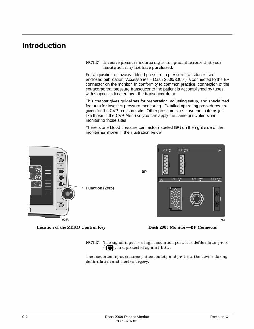
9-2 Dash 2000 Patient Monitor Revision C 2005873-001
Introduction
NOTE: Invasive pressure monitoring is an optional feature that your institution may not have purchased.
For acquisition of invasive blood pressure, a pressure transducer (see enclosed publication "Accessories – Dash 2000/3000") is connected to the BP connector on the monitor. In conformity to common practice, connection of the extracorporeal pressure transducer to the patient is accomplished by tubes with stopcocks located near the transducer dome.
This chapter gives guidelines for preparation, adjusting setup, and specialized features for invasive pressure monitoring. Detailed operating procedures are given for the CVP pressure site. Other pressure sites have menu items just like those in the CVP Menu so you can apply the same principles when monitoring those sites.
There is one blood pressure connector (labeled BP) on the right side of the monitor as shown in the illustration below.
AC Battery
Power
Graph Go/Stop
NBP Go/Stop
Function
Silence Alarm
Trim Knob
Charging Status
ECG 150/ 50
75SPO2 105/ 90
RT70* * * 97NBP 200/ 80
ADT
XX
X/
004A
Function (Zero)
Location of the ZERO Control Key
BP
094
BP
ECG Temp
SPO2
NBP
Dash 2000 Monitor—BP Connector
NOTE: The signal input is a high-insulation port, it is defibrillator-proof ( ) and protected against ESU.
The insulated input ensures patient safety and protects the device during defibrillation and electrosurgery.

Revision C Dash 2000 Patient Monitor 9-3 2005873-001
Assigned BP Names
The invasive pressure connector is labeled BP on the monitor. However, the site name can be changed during the setup procedure. Having a name properly reflect the site is important for proper processing of the waveform since different algorithms are used for processing different pressure sites.
Site names supported and values displayed are: arterial (ART)—systolic, diastolic, and mean femoral (FEM)—systolic, diastolic, and mean pulmonary artery (PA)—systolic, diastolic, and mean central venous (CVP)—mean left atrial (LA)—mean right atrial (RA)—mean intracranial (ICP)—mean special (SP)—mean
Additional site names available in the Neonatal-ICU mode are: umbilical artery catheter (UAC)—systolic, diastolic and mean umbilical venous catheter (UVC)—mean
For reference purposes in this manual, we refer to the connector as BP.

9-4 Dash 2000 Patient Monitor Revision C 2005873-001
Zero Reference
Zeroing the pressure transducer is very important for accurate pressure measurement. Transducers should be zeroed frequently and always before initiating treatment changes based on the pressure data.
To zero the pressure transducer, follow this procedure:
1. Close the transducer stopcock to the patient.
2. Open the venting stopcock to air (atmosphere).
3. Press the FUNCTION key on the front panel of the monitor.
4. Verify that zero reference has been established. (Watch the pressure parameter window for messages.)
5. Close the venting stopcock to air (atmosphere).
6. Open the transducer stopcock to the patient. Within seconds pressure numerics should be displayed in the pressure parameter windows.
As an alternative, select the ZERO option in the pressure menu.
Checklist
1. Patient cable is attached to the BP connector on the monitor.
2. Transducers are level according to unit policy. (Recommended standard is level of right/left atrium.)
3. The transducer is zeroed.
4. Any entrapped air is removed from the system.
NOTE: Refer to the transducer manufacturer’s instructions for suggested means of removing entrapped air from the hydraulic system.
5. Pressure setup is adjusted, if necessary. Details are provided in this chapter.

Revision C Dash 2000 Patient Monitor 9-5 2005873-001
Pressure Monitoring Features
Pressure Information
A labeled pressure waveform will be displayed when the patient cable is connected to the monitor, if enabled from the Display Setup Menu. After a zero reference procedure is done, numerics are displayed in the pressure parameter windows on the right side of the screen.
ART 200/ 80 S mmHg
7294
136/RT70
095
Limits and Units(S denotes systolic limits)
DiastolicValue
MeanValue
SystolicValue
PulseRate Value
ART Pressure Parameter Window
CVP 349/ -99
mmHg
8096
MeanValue
CVP Pressure Parameter Window
The current systolic, diastolic, and mean values are displayed. Some pressures only display a mean value. Limits and the units of measurement may also be displayed. For pressures with multiple values, the limits are labeled (S=systolic, D=diastolic, M=mean). For sites labeled ART, FEM, and UAC, a pulse rate value can be turned on.
The pressure monitoring features are found in the pressure menu. All pressure menus include scales, cursor, site name, limits, zero, and calibration.

9-6 Dash 2000 Patient Monitor Revision C 2005873-001
Getting to the Pressure Menu
To display a pressure menu, use the Trim Knob control to select the pressure parameter label. In this example, we will use the CVP Menu. Remember, selecting with the Trim Knob control is a two-step process—rotate to highlight, then press to select.
CVP 349/ -99 mmHg
8
097 Selecting the CVP Parameter Label
The CVP Menu is displayed at the bottom of the screen.
MAINMENU CURSOR
CVPLIMITS
CHANGENAMECVP
CVPSCALES:
30
ZEROCVP
CVPSETTINGS
098 CVP Menu
With the Trim Knob control, you now can select any of the displayed options:
• SCALES—change the displayed scale for this pressure. • CURSOR—display a new menu for a moveable cursor on the waveform. • LIMITS—display a new menu and an information window to adjust
alarm limits. • CHANGE NAME—change to another name. • ZERO—zero reference transducer. • SETTINGS—displays a new menu to adjust BP filter, pulse rate,
transducer calibration, smart BP, and disconnect alarm feature in the ICU and Operating Room Mode.
These menu options are found in all pressure menus. The only difference is the site name, for example, CVP Cursor, PA Cursor, etc. More details on each option are found in this chapter.

Revision C Dash 2000 Patient Monitor 9-7 2005873-001
Pressure Menu Options
Scales
In most cases, the CVP menu is used in this section to demonstrate the pressure menu options.
The SCALES option allows you to change the scale on which the pressure waveform is displayed on the screen. Changing the scale changes the size of the waveform. Scales can be set in Monitor Defaults.
Follow this procedure:
1. Select CVP SCALES option from the CVP Menu. A popup menu opens showing the scale sizes available. The scale currently used is designated with the pointer (>).
MAINMENU
CVPSCALES:
160
AUTO300200160
100604030>
099 CVP SCALES Popup Menu
NOTE: The auto scale is only an option once the pressure is zeroed.
2. With the Trim Knob control, move the pointer to the desired scale size. The scale on the display will not change until the Trim Knob control is pressed. Pressing the Trim Knob control also closes the popup menu. Selecting AUTO will calculate a scale based on the patient's current blood pressure.
NOTE: Auto scaled waveforms will graph on a slightly different scale than displayed.

9-8 Dash 2000 Patient Monitor Revision C 2005873-001
Cursor
Clear Cursor
This option takes you to a menu that allows you to place a cursor (dashed, horizontal line) across the pressure waveform. The cursor is moveable and is used to give accurate pressure values at selected points on the pressure waveform. A numeric value is displayed on the screen to the right of the cursor.
To use this feature, proceed as follows:
1. Select the CURSOR option from the Pressure menu. The CURSOR menu appears.
MAINMENU
CLEARCURSOR
CVPCURSOR
PREVMENU
100 CVP CURSOR Menu
2. Select CVP CURSOR option from the CVP CURSOR Menu. Another popup menu opens.
MAINMENU
CVPCURSOR USE TO
POSITIONCURSOR ONWAVEFORMPREV.
MENU
100A CVP Cursor Popup Menu
The monitor automatically calculates a scale and the new scale and cursor are displayed with the waveform. A numeric cursor value is displayed to the right of the cursor.
CVP2
25
-1
12
New Scale Cursor Cursor Value
101 Cursor on CVP Waveform
3. With the popup menu open, rotate the Trim Knob control to move the cursor. The cursor value changes as you move the cursor.
4. Press the Trim Knob control to close the popup menu. The cursor remains on the waveform.
To remove the cursor from the waveform, select CLEAR CURSOR option from the previous menu. This is a direct action menu option.
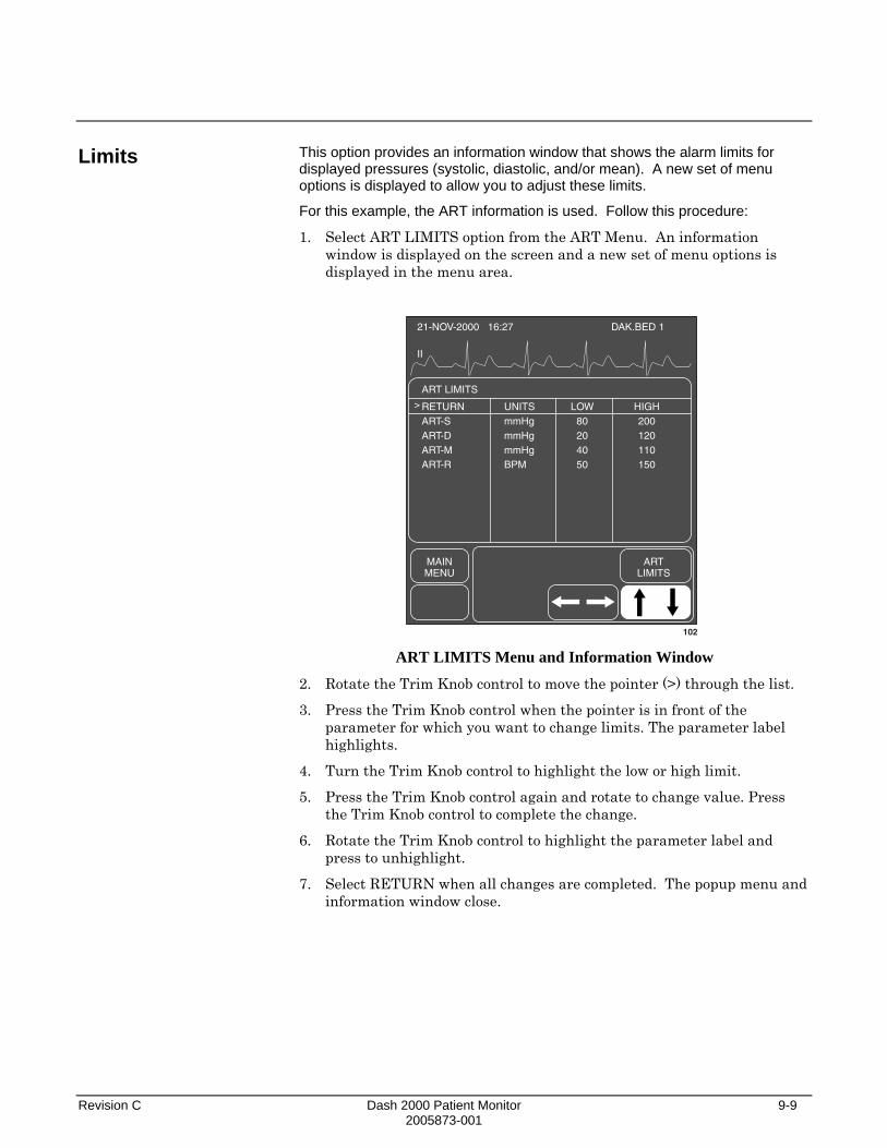
Revision C Dash 2000 Patient Monitor 9-9 2005873-001
Limits
This option provides an information window that shows the alarm limits for displayed pressures (systolic, diastolic, and/or mean). A new set of menu options is displayed to allow you to adjust these limits.
For this example, the ART information is used. Follow this procedure:
1. Select ART LIMITS option from the ART Menu. An information window is displayed on the screen and a new set of menu options is displayed in the menu area.
21-NOV-2000 16:27
II
DAK.BED 1
ART LIMITS
RETURNART-SART-DART-MART-R
UNITSmmHgmmHgmmHgBPM
LOW80204050
HIGH200120110150
MAINMENU
ARTLIMITS
>
102 ART LIMITS Menu and Information Window
2. Rotate the Trim Knob control to move the pointer (>) through the list.
3. Press the Trim Knob control when the pointer is in front of the parameter for which you want to change limits. The parameter label highlights.
4. Turn the Trim Knob control to highlight the low or high limit.
5. Press the Trim Knob control again and rotate to change value. Press the Trim Knob control to complete the change.
6. Rotate the Trim Knob control to highlight the parameter label and press to unhighlight.
7. Select RETURN when all changes are completed. The popup menu and information window close.
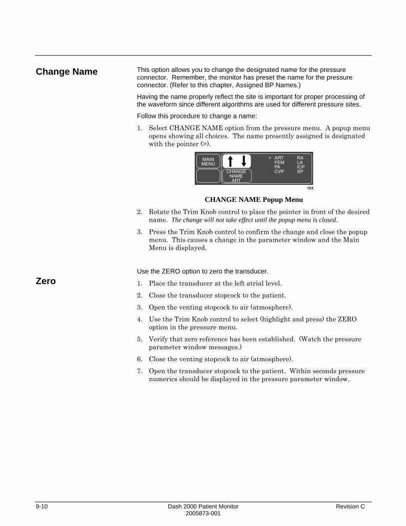
9-10 Dash 2000 Patient Monitor Revision C 2005873-001
Change Name
Zero
This option allows you to change the designated name for the pressure connector. Remember, the monitor has preset the name for the pressure connector. (Refer to this chapter, Assigned BP Names.)
Having the name properly reflect the site is important for proper processing of the waveform since different algorithms are used for different pressure sites.
Follow this procedure to change a name:
1. Select CHANGE NAME option from the pressure menu. A popup menu opens showing all choices. The name presently assigned is designated with the pointer (>).
MAINMENU
CHANGENAMEART
ARTFEMPACVP
RALAICPSP
>
103 CHANGE NAME Popup Menu
2. Rotate the Trim Knob control to place the pointer in front of the desired name. The change will not take effect until the popup menu is closed.
3. Press the Trim Knob control to confirm the change and close the popup menu. This causes a change in the parameter window and the Main Menu is displayed.
Use the ZERO option to zero the transducer.
1. Place the transducer at the left atrial level.
2. Close the transducer stopcock to the patient.
3. Open the venting stopcock to air (atmosphere).
4. Use the Trim Knob control to select (highlight and press) the ZERO option in the pressure menu.
5. Verify that zero reference has been established. (Watch the pressure parameter window messages.)
6. Close the venting stopcock to air (atmosphere).
7. Open the transducer stopcock to the patient. Within seconds pressure numerics should be displayed in the pressure parameter window.

Revision C Dash 2000 Patient Monitor 9-11 2005873-001
Settings
This option provides access to another popup menu that offers special options which influence the processing of the pressure signal. The set of options offered varies depending on the pressure site and the selected monitory type.
MAINMENU
BPFILTER:12 Hz
PULSERATE:OFF
PREV.MENU
CALIBTRANSDUC
SMART BP:ON
DISCONNALARM:
OFF
BPSET1 BP Settings Menu for pressures sites ART, FEM
(Adult ICU and Operating Room mode)
MAINMENU
BPFILTER:12 Hz
PULSERATE:OFF
PREV.MENU
CALIBTRANSDUC
BPSET2 BP Settings Menu for pressures sites ART, FEM, UAC
(Neonatal ICU mode)
MAINMENU
BPFILTER:12 Hz
PREV.MENU
CALIBTRANSDUC
BPSET3 BP Settings Menu for all other pressures sites

9-12 Dash 2000 Patient Monitor Revision C 2005873-001
BP Filter
Calibrate Transducer
Select the BP FILTER option of the SETTINGS menu to open a popup menu. Use the Trim Knob control to select a 12 or 40 Hz filter.
MAINMENU
CALIBTRANSDUC
BPFILTER:12 Hz
12 Hz40 HzHELP
PREV.MENU
>
104 BP FILTER Popup Menu
The 12-Hz filter is recommended for typical monitoring applications. The 40-Hz filter allows higher frequency waveform components to be processed. This may result in elevated pressure values.
The CALIB TRANSDUC option allows you to adjust the monitor for any transducer error.
NOTE: Error is determined when pressure calibration is measured with another instrument such as a mercury manometer.
1. Select CALIB TRANSDUC option from the Settings menu. A new menu is displayed with two options to adjust for transducer error.
MAINMENU
CAL#:100
ADJUSTTO
MMHG
PREV.MENU
105 CALIBRATE TRANSDUCER Menu
2. Select one of the two menu options. Adjusting one option automatically adjusts the other.
• CAL # 100—Open a popup menu to enter the percentage of error. Use this option when the calibration error is already known.
NOTE: Always make sure the CAL# is at 100 when making a new adjustment.
For example, if it is known that this transducer measured 2% high, rotate the Trim Knob control to 102. When you close the popup menu the monitor will now compensate for the error.
NOTE: If you apply a known pressure, such as 100, and the monitor displays 102 for that pressure site, adjust the CAL# to the number displayed.
You must close the popup menu before a change is displayed in the values window.
• ADJUST TO MMHG—Open a popup menu to change the millimeters of mercury.

Revision C Dash 2000 Patient Monitor 9-13 2005873-001
Smart BP
Pulse Rate
Smart BP is a feature found in ART and FEM Settings menus.
NOTE: The Smart BP feature is not available when the monitor is set up for Neonatal-ICU mode.
Smart BP is an arterial (femoral) artifact rejection program which substantially reduces the occurrences of needless alarms by eliminating most of the alarms associated with zeroing the transducer, fast flushing the system, and drawing blood.
When Smart BP is on, and the system recognizes one of these events, the arterial (femoral) alarms are deactivated and the systolic and diastolic numerics are replaced with Xs. The message ”ARTIFACT” is displayed. The mean pressure value is displayed throughout the artifact occurrence.
Safety Features: If zeroing, fast flushing, or drawing blood is not accomplished within certain time frames, alarms will sound. When artifact is detected, Smart BP begins to search for the return of a pulsatile pressure. When 15-20 beats have been detected, numerics are displayed and alarms are reactivated. If pressure remains below 10 mmHg for more than 14 seconds, the alarms will reactivate. During sustained high pressure (drawing blood), you have a maximum of two minutes before alarms reactivate. To turn Smart BP on/off, select the SMART BP option from the Settings menu. This feature can be set in Monitor Defaults.
Another special feature is PULSE RATE. This feature is found in ART, FEM, and UAC (neonatal mode only) pressure sites. When turned on, a Rate value is displayed in the appropriate parameter values window.
ART 200/ 80 S mmHg
RT. 70
7294
136/PulseRate on
106 Pulse Rate Displayed in ART Parameter Window
To turn the pulse rate value on and off, simply select PULSE RATE in the applicable Settings menu.
9-14 Dash 2000 Patient Monitor Revision C 2005873-001
Disconnect Alarm
The DISCONN ALARM feature is found in ART and FEM Settings menus.
NOTE: This feature is not available when the monitor is set up for Neonatal-ICU mode.
If the mean pressure falls below 25 mmHg and the disconnect alarm is on, a Warning alarm sounds and the message DISCONNECTED is displayed in the values window. Check your patient immediately in the event the catheter has dislodged.
To turn this feature off and on, select DISCONN ALARM option from the appropriate Settings menu. This feature can be set off or on in Monitor Defaults. You cannot change the alarm level. It will always be a warning alarm.

Revision C Dash 2000 Patient Monitor 9-15 2005873-001
Troubleshooting
Problem: Displayed pressure values are different than expected Problem: Smart BP is on. Artifact is sensed without flush, draw, or zero
Solution: Check tubing for bubbles.
Remove excessive tubing.
Check phlebostatic axis placement of transducer.
Rezero pressure: 1. Place the transducer at the left atrial level. 2. Close transducer stopcock to patient. 3. Open the venting stopcock to air. 4. Press FUNCTION key on the front panel of the monitor. 5. Close the venting stopcock to air. 6. Open transducer stopcock to patient.
Solution: Turn Smart BP OFF then ON. If problem persists, you may need to disable Smart BP by turning it off for that pressure.
Use Alarm Pause feature prior to drawing blood to reduce unnecessary alarms if Smart BP is disabled.

9-16 Dash 2000 Patient Monitor Revision C 2005873-001
For your notes

Revision C Dash 2000 Patient Monitor 10-1 2005873-001
10 NBP Introduction....................................................................................10-2
Checklist....................................................................................10-5
Patient Preparation .......................................................................10-6
NBP Monitoring Features .............................................................10-7 NBP Information ......................................................................10-7
Mean Arterial Pressure.......................................................10-7 Systolic Search.....................................................................10-8 NBP Go/Stop Key.................................................................10-8 Power Key ............................................................................10-8
Getting to the NBP Menu ........................................................10-9
NBP Menu Options......................................................................10-10 NBP Auto.................................................................................10-10 NBP Stat..................................................................................10-11
Early Systolic Measurement.............................................10-11 NBP Limits..............................................................................10-12 NBP Settings...........................................................................10-13
Cuff Size .............................................................................10-14 Initial Cuff Pressure..........................................................10-14
Review NBPs...........................................................................10-15 Clear NBP Reading.................................................................10-15
Troubleshooting ...........................................................................10-16 NBP Status Messages.............................................................10-16

10-2 Dash 2000 Patient Monitor Revision C 2005873-001
Introduction
A patient's vital signs may vary dramatically during the use of cardiovascular agents such as those that raise or lower blood pressure or those that increase or decrease heart rate.
Because treatment protocol based on the patient's blood pressure may rely on specific values and differing measurement methods, such as auscultatory, clinicians should note a possible variance from values obtained with this unit in planning patient care management. The Dash 2000 patient monitor values are based on the oscillometric method of noninvasive blood pressure measurement and correspond to comparisons with intra-aortic values within ANSI/AAMI Standards for accuracy.
GENERAL WARNINGS The NBP parameter will not measure blood pressure effectively on patients who are experiencing seizures or tremors.
Arrhythmias will increase the time required by the NBP parameter to determine a blood pressure and may extend the time beyond the capabilities of the parameter.
Devices that exert pressure on tissue have been associated with purpura, skin avulsion, compartmental syndrome, ischemia, and/or neuropathy. To minimize these potential problems, especially when monitoring at frequent intervals or over extended periods of time, make sure the cuff is applied appropriately and examine the cuff site and the limb distal to the cuff regularly for signs of impeded blood flow.
Do not apply external pressure against cuff while monitoring. Doing so may cause inaccurate blood pressure values.
Use care when placing cuff on extremity used to monitor other patient parameters.
Revision C Dash 2000 Patient Monitor 10-3 2005873-001
GENERAL CAUTIONS Accuracy of NBP measurement depends on using a cuff of the proper size. It is essential to measure the circumference of the limb and to choose the proper cuff size.
The pulse rate derived from an NBP determination may differ from the heart rate derived from an ECG waveform because the NBP parameter measures actual peripheral pulses, not electrical signals or contractions from the heart. Differences may occur because electrical signals at the heart occasionally fail to produce a peripheral pulse or the patient may have poor peripheral perfusion. Also, if a patient's beat-to-beat pulse amplitude varies significantly (e.g., because of pulsus alternans, atrial fibrillation, or the use of a rapid-cycling artificial ventilator), blood pressure and pulse rate readings can be erratic, and an alternate measuring method should be used for confirmation.
GENERAL NOTES A patient's vital signs may vary dramatically during the use of cardiovascular agents such as those that raise or lower blood pressure or those that increase or decrease heart rate.
Automatic noninvasive blood pressure monitoring uses the oscillometric method of measurement. To understand how this method works, we’ll compare it to the auscultative method. With auscultation, the clinician listens to the blood pressure and determines the systolic and diastolic pressures. The mean pressure can then be calculated with reference to these pressures as long as the arterial pressure curve is normal. Since the monitor cannot hear the blood pressure, it measures cuff pressure oscillation amplitudes. Oscillations are caused by blood pressure pulses against the cuff. The oscillation with the greatest amplitude is the mean pressure. This is the most accurate parameter measured by the oscillometric method. Once the mean pressure is determined, the systolic and diastolic pressures are calculated with reference to the mean.
Simply stated, auscultation measures systolic and diastolic pressures and the mean pressure is calculated. The oscillometric method measures the mean pressure and determines the systolic and diastolic pressures.

10-4 Dash 2000 Patient Monitor Revision C 2005873-001
NOTE: Due to the difference in these methods, one cannot be used to check the accuracy of the other.
NBP Cable Connector
107
BP
ECG Temp
SPO2
NBP
Dash 2000 Monitor—NBP Connector
NOTE: The NBP cable connector is insulated and it is defibrillator-proof ( ). Use only the BP cuffs listed in the enclosed publication "Accessories – Dash 2000/3000". These cuffs ensure patient safety and protect the device during defibrillation and electrosurgery.

Revision C Dash 2000 Patient Monitor 10-5 2005873-001
Checklist
1. A cuff appropriate for limb size has been selected.
2. Cuff is properly placed on patient.
3. Patient cable is connected to monitor.
NOTE: Do not connect more than one NBP patient cable.
4. Tubes between the cuff and the monitor are not kinked or blocked.
5. Correct CUFF SIZE has been selected from the NBP menu.
6. Confirm that the cuff is fully deflated before positioning on the patient.
7. Start an NBP reading following auto or stat mode procedures as detailed in this section, or use the NBP GO/STOP control key.
8. The measurement should be performed on the left arm if feasible. Roll up sleeve before measurement. Only very thin fabrics will not impair the measurement.
9. Check that rolled up sleeve does not constrict the vessels.
10. The arm should be placed on a surface that is level with the heart. The palm of the hand should face up.
11. Position patient so that no external pressure is applied against cuff while monitoring. External pressure may cause inaccurate blood pressure values.
WARNING The cuff size selected in the NBP menu and the cuff size used must be correct to obtain reliable NBP data and to prevent overpressure in neonatal or pediatric use.

10-6 Dash 2000 Patient Monitor Revision C 2005873-001
Patient Preparation
Cuff selection and application are important. Inappropriate selection or improper application of the cuff will result in erroneous measurements.
WARNINGS The system is designed for use with dual-hose cuffs and tubing. The use of single-hose cuffs with dual hose tubing can result in unreliable and inaccurate NBP data.
Use care when placing cuff on extremity used to monitor other patient parameters.
Do not place the cuff on a limb being used for A-V Fistulas, intravenous infusion, or any area where circulation is compromised or has the potential to be compromised.
Cuff selection:
1. Identify patient limb circumference.
2. Select appropriate cuff: limb circumference is identified on each cuff.
Cuff placement:
1. Place cuff snugly around extremity being used.
2. Marking on cuff should match artery location.
3. Cuff should be 2 to 5 cm (1 to 2 inches) above the elbow if using brachial artery.
4. The air pad should be exactly over the brachial artery. Tubing is immediately to the right or left of the brachial artery to prevent kinking when elbow is bent.
For further information on cuffs, please contact your sales/service representative.

Revision C Dash 2000 Patient Monitor 10-7 2005873-001
NBP Monitoring Features
NBP Information
Mean Arterial Pressure
There is no waveform displayed when monitoring with the non-invasive blood pressure technique. However, numerics are displayed in the NBP parameter window.
NBP 200/ 80S mmHg
58 16:27SEC ADT
7187
111/
108
Systolic Value
CountdownTimer
Diastolic Value
Limits and Units
Mean Value
Cuff Size(Adult)
NBP Parameter Label and Window The current systolic, diastolic, and mean values are displayed. Limits and the units of measurement may also be displayed. The limits displayed are labeled (S=systolic, D=diastolic, M=mean). The cuff size and time of last measurement are also displayed. The time is displayed with a 24-hour clock. During a measurement, the cuff inflation pressure (updated every second) is displayed in place of the mean value.
If AUTO mode is on, a countdown timer is displayed in the lower left corner.
The NBP values change to "X" if no NBP monitoring has taken place for 2 hours in ADULT-ICU mode, 15 minutes in OPERATING ROOM mode, and 12 hours in NEONATAL-ICU mode.
The NBP monitoring features are found in the NBP Menu. These features include AUTO and STAT modes, reviewing previous NBP measurements, cuff size, alarm limits, and clearing readings.
There are several conditions that may cause the NBP parameter block to display the mean arterial pressure (MAP) without an associated systolic and diastolic reading. These conditions include:
• Very low systolic and diastolic amplitude fluctuations (e.g. patients in shock).
• A very small difference between the systolic and MAP calculation in relation to the difference between diastolic and MAP.
• A break in the integrity of the system (e.g. loose connections or leak).
Be sure to perform a visual inspection to ensure system integrity.
NOTE: If MAP is the only value displayed, X's will appear in place of systolic and diastolic values.

10-8 Dash 2000 Patient Monitor Revision C 2005873-001
Systolic Search
NBP Go/Stop Key
Power Key
NOTE: The cuff target pressure must be higher than the patient's systolic pressure to obtain an accurate systolic and diastolic reading.
If a systolic blood pressure is not found, the Dash monitor will search for a systolic value at a cuff pressure higher than the initial target pressure. This will occur only once per NBP determination. The maximum pressure allowed in systolic search is limited by the normal range for cuff pressures.
The NBP GO/STOP key on the front of the monitor is a quick way to take one measurement without going into the NBP menu. It can also be used to stop a measurement already in progress.
If you turn the power off with the POWER key on the front of the monitor, NBP is also turned off. This applies to both auto NBP (if running) and manual NBP. Turning the power on again enables manual NBP. It does not automatically restart auto NBP.

Revision C Dash 2000 Patient Monitor 10-9 2005873-001
Getting to the NBP Menu
To display the NBP Menu, use the Trim Knob control to select the pressure parameter label. Remember, selecting with the Trim Knob control is a two-step process—rotate to highlight, then press to select.
NBP 200/ 80S mmHg
58 16:27SEC ADT
7187
111/
109 Selecting the NBP Parameter Label
The NBP Menu is displayed at the bottom of the screen.
MAINMENU
NBPLIMITS
NBPSTAT:OFF
NBPAUTO:OFF
CLEARNBP
READING
NBPSETTINGS
110
REVIEWNBPS
NBP Menu
With the Trim Knob control, you now can select any of the displayed options:
• NBP AUTO—start/stop the automatic mode; select appropriate time interval.
• NBP STAT—start 5 minutes of continuous, sequential NBP measurements. (Not available in Neonatal-ICU mode.)
• NBP LIMITS—display an information window and a new menu to adjust systolic, diastolic, and mean limits.
• NBP SETTINGS—display a new menu to adjust the cuff size and the target inflation pressure.
• REVIEW NBPS—review previous NBP measurements in Vital Signs.
• CLEAR NBP READING—remove the values from the NBP parameter window.
Detailed information on each option is found in this chapter.
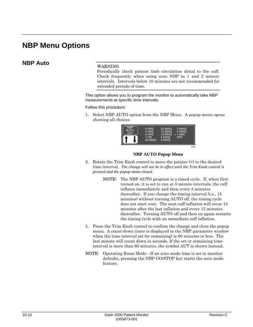
10-10 Dash 2000 Patient Monitor Revision C 2005873-001
NBP Menu Options
NBP Auto
WARNING Periodically check patient limb circulation distal to the cuff. Check frequently when using auto NBP in 1 and 2 minute intervals. Intervals below 10 minutes are not recommended for extended periods of time.
This option allows you to program the monitor to automatically take NBP measurements at specific time intervals.
Follow this procedure:
1. Select NBP AUTO option from the NBP Menu. A popup menu opens showing all choices.
NBPAUTO:OFF
8 HRS4 HRS2 HRS1 HR30 MINS
20 MINS15 MINS10 MINS5 MINS4 MINS
3 MINS2 MINS1 MINOFF
>
111 NBP AUTO Popup Menu
2. Rotate the Trim Knob control to move the pointer (>) to the desired time interval. The change will not be in effect until the Trim Knob control is pressed and the popup menu closed.
NOTE: The NBP AUTO program is a timed cycle. If, when first turned on, it is set to run at 5-minute intervals, the cuff inflates immediately and then every 5 minutes thereafter. If you change the timing interval (i.e., 15 minutes) without turning AUTO off, the timing cycle does not start over. The next cuff inflation will occur 15 minutes after the last inflation and every 15 minutes thereafter. Turning AUTO off and then on again restarts the timing cycle with an immediate cuff inflation.
3. Press the Trim Knob control to confirm the change and close the popup menu. A count-down timer is displayed in the NBP parameter window when the time interval set (or remaining) is 60 minutes or less. The last minute will count down in seconds. If the set or remaining time interval is more than 60 minutes, the symbol AUT is shown instead.
NOTE: Operating Room Mode—If an auto mode time is set in monitor defaults, pressing the NBP GO/STOP key starts the auto mode feature.

Revision C Dash 2000 Patient Monitor 10-11 2005873-001
NBP Stat Early Systolic Measurement
NOTE: The NBP STAT feature is not available when the monitor is set up for Neonatal-ICU mode. Please do not use the STAT mode on neonatal patients when the monitor is set up for Adult-ICU or Operating Room mode.
NBP STAT enables 5 minutes of continuous, sequential, automatic NBP measurements. Follow this procedure:
• Activate the NBP STAT option of the NBP menu to start 5 minutes of continuous, sequential NBP measurement.
• Press OFF to discontinue the STAT process before the 5-minute period is up, or simply press NBP GO / STOP key on the front of the monitor.
Early systolic measurement is a feature of the NBP STAT mode. As soon as you enter NBP STAT mode, cuff inflation begins, a measurement is taken, and the systolic, diastolic, and mean values are displayed. Thereafter, the systolic value will be displayed shortly after the measurement starts. When the measurement is complete the monitor will beep and the diastolic and mean values will be displayed.

10-12 Dash 2000 Patient Monitor Revision C 2005873-001
NBP Limits
This option provides an information window that shows the alarm limits for systolic, diastolic, and mean pressures. A new set of menu options is displayed to allow you to adjust these limits.
Follow this procedure:
1. Select NBP LIMITS from the NBP Menu. An information window is displayed on the screen and a new set of menu options is displayed in the menu area.
21-NOV-2000 16:27
II
DAK.BED 1
NBP LIMITS
RETURNNBP-SNBP-DNBP-M
UNITSmmHgmmHgmmHg
LOW202040
HIGH200120140
MAINMENU
NBPLIMITS
>
112 NBP LIMITS Menu and Information Window
2. Rotate the Trim Knob control to move the pointer (>) through the list.
3. Press the Trim Knob control when the pointer is in front of the parameter for which you want to change default limits. The parameter label highlights.
4. Turn the Trim Knob control to highlight the low or high limit.
5. Press the Trim Knob control again and rotate to change value. Press the Trim Knob control to complete the change.
6. Rotate the Trim Knob control to highlight the parameter label and press to unhighlight.
7. Select RETURN when all changes are completed. The popup menu and information window close.

Revision C Dash 2000 Patient Monitor 10-13 2005873-001
NBP Settings With this option a new set of menu options is displayed to allow you to choose the cuff size and the initial cuff inflation pressure.
Follow this procedure:
Select NBP SETTINGS from the NBP Menu.
MAINMENU
INIT. CUFFPRESSURE:
AUTO
CUFFSIZE:
ADULT
110A
PREV.MENU
NBP Settings Menu
With the Trim Knob control, you can now select any of the displayed options.
• CUFF SIZE—select the type of cuff being used (adult, pediatric, neonatal).
• INIT. CUFF PRESSURE—determine the target inflation pressure for the first measurement.

10-14 Dash 2000 Patient Monitor Revision C 2005873-001
Cuff Size
Initial Cuff Pressure
This option programs the monitor for the appropriate inflation pressure. The cuff size setting is based on the patient's age. There are three choices—Adult, Pediatric, and Neonatal. This can be set in Monitor Defaults.
A label showing your choice—ADT, PED, NEO—is displayed at the bottom of the parameter window.
If you need to select a different size, follow this procedure:
1. Select CUFF SIZE option from the NBP Settings Menu. A popup menu opens displaying the three options.
MAINMENU
CUFFSIZE:
ADULT ADULTPEDIATNEONATEPREV.
MENU
>
113 CUFF SIZE Popup Menu
2. Use the Trim Knob control to make your selection. The change will not be in effect until the Trim Knob control is pressed and the popup menu closed.
3. Press the Trim Knob control to close the popup menu.
This option allows you to set the target inflation pressure for the first measurement. 1. Select INIT CUFF PRESSURE option from the NBP Settings Menu to
display the following popup menu.
MAINMENU
INIT.CUFFPRESSURE:
AUTO AUTO
CUFFSIZE:
ADULT
113A
PREV.MENU
INIT CUFF PRESSURE Popup Menu
2. Rotate the Trim Knob control to scroll through the list of inflation pressures. The choices available depend on the cuff size. For adult and pediatric cuff size, the choices are AUTO and 100 mmHg to 250 mmHg, The choices for neonatal cuff size are AUTO, 100 mmHg to 140 mmHg. Inflation pressures are adjusted in increments of 5 mmHg. The inflation pressure for the AUTO setting is as follows:
Adult, 160 mmHg Pediatric, 140 mmHg Neonatal, 110 mmHg
3. Press the Trim Knob control to set the inflation pressure and close the popup menu.
Cuff inflation thereafter is automatically determined by multiple factors including mode of operation, cuff size, and previous reading.

Revision C Dash 2000 Patient Monitor 10-15 2005873-001
Review NBPs
Clear NBP Reading
The monitor can store up to 96 NBP readings which can be reviewed in Vital Signs. This would be equivalent to running auto mode at 15 minute intervals for 24 hours. Readings older than 24 hours are cleared from Vital Signs.
1. Select REVIEW NBPS option from the NBP Menu. The Vital Signs information window is displayed with the data sorted so NBP readings appear first in the list.
21-MAR-2001 17:10
II
DAK.BED 1
MAINMENU
PREV.MENU
SPECIFICTIME
PAGEUP
PAGEDOWN
VIEWOLDER
VIEWNEWER
TIMEINTERVAL:
VITAL SIGNS 21-MAR-2001 17:10
RETURN
NBP-SNBP-DNBP-MNBP-R
ALARMS
21-MAR16:45117638569
OFF
22-MAR17:00114739369
OFF
112A REVIEW NBPS Menu and Information Window
2. Use the Trim Knob control to select menu options. Refer to the Patient Data chapter, Vital Signs, to review details.
NOTE: TIME INTERVAL and SPECIFIC TIME do not work with episodic events such as NBP.
3. Select PREVIOUS MENU to return to the NBP menu.
If you want to remove the values displayed in the NBP parameter window, select this option. The values will be replaced with "X". This action also removes those values from Vital Signs history.

10-16 Dash 2000 Patient Monitor Revision C 2005873-001
Troubleshooting
NBP Status Messages
A status message will be displayed in the NBP values window if a measurement is unable to be completed. Following is an alphabetical list of the status messages with monitor response and action to take.
STATUS MESSAGE MONITOR RESPONSE SOLUTION
CUFF INFLAT OVER 5 MINS System status alarm. Auto mode will shut off.
Check cuff, if no air is in cuff, try another measurement. If problem persists, contact service.
If air is in cuff, remove cuff and contact service.
DEFLATION FAIL System status alarm. Auto mode will shut off.
Remove cuff and contact service.
HARDWARE FAIL System status alarm. Auto mode will shut off.
Contact service.
NO DETERMINATION System status alarm. Auto mode will shut off.
Check patient and cuff placement; try another measurement. If problem persists, contact service.
OVER PRESSURE System status alarm. Remove cuff and contact service.
PUMP TIMEOUT (inflation failure/pressure leak)
System status alarm. Check connections between cuff and monitor; try another measurement. If problem persists, contact service.
Check for worn connector ”O” rings. Contact service.
TOTAL TIMEOUT (measurement > 3 minutes)
System status alarm. Auto mode will shut off.
Possible excessive patient movement or arrhythmia condition. Check patient; try another measurement.
For neonatal mode, the status message will appear after 90 seconds.
Any two consecutive NBP status messages will shut Auto mode off if it is running.
A message will clear when the next measurement is initiated, or a message can be cleared manually with the CLEAR NBP READING option in the NBP menu.
An NBP status message will also be included in the graph header in an abbreviated form, when applicable.

Revision C Dash 2000 Patient Monitor 10-17 2005873-001
Problem: Erroneous NBP measurement
Solutions 1. Check for proper cuff size:
a. Too small a cuff can give an erroneously high value.
b. Too large a cuff can give an erroneously low value.
2. Check for residual air left in the cuff from a previous measurement.
3. Make sure cuff is not too tight or too loose.
4. Make sure cuff and heart are at same level, otherwise hydrostatic pressure will offset the NBP value.
5. Minimize patient movement during measurement.
6. Watch for pulsus paradoxus.
7. Check for leak in cuff or tubing.
8. Patient may have a weak pulse.
9. Calibration may be necessary.


Revision C Dash 2000 Patient Monitor 11-1 2005873-001
11 SPO2 Introduction....................................................................................11-2
Neonates and Infants ....................................................................11-3
Checklist .........................................................................................11-4
Patient Preparation .......................................................................11-5
Signal and Data Validity...............................................................11-6 Signal Strength Indicator.........................................................11-6 Quality of SPO2 Waveform ......................................................11-6 Stability of SPO2 Values ..........................................................11-7
SPO2 Monitoring Features ...........................................................11-8 SPO2 Information.....................................................................11-8 Getting to the SPO2 Menu.......................................................11-9
SPO2 Menu Options ....................................................................11-10 Size...........................................................................................11-10 SPO2 Limits ............................................................................11-11 Rate Volume............................................................................11-12 Rate..........................................................................................11-12
Probe Off Patient Condition........................................................11-13
Troubleshooting ...........................................................................11-14 SPO2 Messages .......................................................................11-14

11-2 Dash 2000 Patient Monitor Revision C 2005873-001
Introduction
WARNING SpO2 monitoring may interfere with MRI operation.
NOTE: SpO2 and SPO2 are used interchangeably in this chapter. SPO2 monitoring is a noninvasive technique used to measure the amount of oxygenated hemoglobin and pulse rate by measuring the absorption of selected wavelengths of light (functional saturation). The light generated in the probe passes through the tissue and is converted into an electrical signal by the photodetector in the probe. The monitor processes the electrical signal and displays on the screen a waveform and digital values for SpO2 and pulse rate. This chapter provides guidelines for successful SPO2 monitoring.
114
SPO2 Cable Connector
BP
ECG Temp
SPO2
NBP
Dash 2000 Monitor—SPO2 Cable Connector
NOTE: The signal input is insulated and it is defibrillator-proof ( ). The insulated input ensures patient safety and protects the device during defibrillation and electrosurgery.

Revision C Dash 2000 Patient Monitor 11-3 2005873-001
Neonates and Infants
WARNING The display of inaccurate pulse oximetry (SPO2) values has been linked to the presence of poor signal strength or artifact due to patient motion during signal analysis. This condition is most likely to be encountered when the monitor is used on neonates or infants. These same conditions in adults do not impact the pulse oximetry values to the same extent.
When using pulse oximetry on neonates and infants, always observe the following precautions.
PRECAUTIONS
We recommend the application of the following criteria when using the pulse oximetry function on neonates and infants:
1. The peripheral pulse rate (PPR) as determined by the pulse oximetry function must be within 10% of the heart rate, and
2. the pulse oximetry signal strength indicator must have 2 or 3 asterisks displayed, and
3. six seconds of artifact-free waveform must be present, or
4. stable pulse oximetry values are displayed for six seconds.
Procedures or devices previously applied in your facility for pulse oximetry monitoring should be used in the event that the pulse oximetry value from the Dash monitor cannot be validated by the above criteria.

11-4 Dash 2000 Patient Monitor Revision C 2005873-001
Checklist
1. SPO2 probe is correctly positioned on the patient. (Follow instructions provided with the probe of choice.)
2. Patient cable is connected to the monitor.
3. SPO2 setup is adjusted, if necessary. Follow detailed procedures within this chapter.
Revision C Dash 2000 Patient Monitor 11-5 2005873-001
Patient Preparation
Prepare the patient for SPO2 monitoring using the following steps:
1. Choose the probe that is best suited to your patient—ear, finger, disposable, reusable, etc.
NOTE: Nellcor’s RS-10 reflective probe is not recommended for use. Use only the probes listed in the enclosed publication "Accessories – Dash 2000/3000". Contact your sales/service representative for other probe options.
2. Clean the surface of the probe before and after each patient use.
3. Following the instructions provided with the probe, correctly position and attach the probe to your patient.
Be aware of the following general safety precautions when using SPO2 probes:
WARNINGS DATA VALIDITY—Do not expose probe detector to strong ambient light while monitoring a patient. A poor signal may result.
DATA VALIDITY—Do not allow tape to block the probe light detector.
DATA VALIDITY—Check that the SPO2 waveform is physiological in shape.
PATIENT SAFETY—Prolonged monitoring may require changing the probe site periodically. Move the probe if there is any sign of skin irritation or impaired circulation. Change the probe site at least every four hours to prevent ischemic skin necrosis. Be particularly careful when monitoring neonates. If required, reduce the application periods to half the times recommended above.
PATIENT SAFETY—If a probe is damaged in any way, discontinue use immediately.
Be sure to read all literature accompanying probes for specific safety information.

11-6 Dash 2000 Patient Monitor Revision C 2005873-001
Signal and Data Validity
Signal Strength Indicator
Quality of SPO2 Waveform
It is extremely important to determine that the probe is attached to the patient correctly and the data is verifiable. To make this determination, three indications from the monitor are of assistance—signal strength indicator, quality of the SPO2 waveform, and the stability of the SPO2 values. It is critical to observe all three indications simultaneously when ascertaining signal and data validity.
The signal strength indicator is displayed within the SPO2 values window. This indicator consists of 0, 1, 2, or 3 (strongest) asterisks depending on the strength of the signal. Proper environmental conditions and probe attachment will help to ensure a strong signal.
Under normal conditions, the SPO2 waveform corresponds to (but is not proportional to) the arterial pressure waveform. The typical SPO2 waveform indicates not only a good waveform, but helps the user find a probe placement with the least noise spikes present. The figure below represents an SPO2 waveform of good quality.
115 Good Quality SPO2 Waveform
If noise (artifact) is seen on the waveform because of poor probe placement, the photodetector may not be flush with the tissue. Check that the probe is secured and the tissue sample is not too thick. Pulse rate is determined from the SPO2 waveform which can be disrupted by a cough or other hemodynamic pressure disturbances. Motion at the probe site is indicated by noise spikes in the normal waveform. (See the figure below.) It has been noted that letting the patient view the SPO2 waveform enables them to assist in reducing motion artifact.
116 SPO2 Waveform with Artifact
Revision C Dash 2000 Patient Monitor 11-7 2005873-001
Stability of SPO2 Values
The stability of the displayed SPO2 values can also be used as an indication of signal validity. Although stability is a relative term, with a small amount of practice one can get a good feeling for changes that are artifactual or physiological and the speed of each.
Messages are provided in the SPO2 values window to aid you in successful SPO2 monitoring. (Refer to this chapter, Troubleshooting.)
WARNING In the monitoring of patients the coincidence of adverse conditions may lead to a disturbed signal going unnoticed. In this situation artifacts are capable of simulating a plausible parameter reading, so that the monitor fails to sound an alarm. In order to ensure reliable patient monitoring, the proper application of the probe and the signal quality must be checked at regular intervals.

11-8 Dash 2000 Patient Monitor Revision C 2005873-001
SPO2 Monitoring Features
SPO2 Information
A waveform, labeled SPO2, will be displayed on the screen when the patient cable is connected to the monitor. Numerics are also displayed in the SPO2 parameter windows on the right side of the screen.
NOTE: Visual indication of the patient’s pulse is not proportional to the pulse amplitude.
SPO2 105/ 90%
***RT. 70100
Strength ofSignal
Indicator
Pulse RateValue
Limits and Units
SPO2 Value
117 SPO2 Parameter Window
The current SPO2 value and the derived pulse rate (RT) are displayed. The asterisks indicate the strength of the signal (three asterisks indicate the strongest signal).
The SPO2 measurements are averaged over a 6-second period of time in adult mode and 12 seconds in neonatal mode. The different averaging time in neonatal mode is to help decrease false alarms related to patient motion artifact.
The monitor display is updated every 2 seconds.
The SPO2 monitoring features are found in the SPO2 menu. These features include waveform size, alarm limit adjustment, display of RATE, and RATE volume.

Revision C Dash 2000 Patient Monitor 11-9 2005873-001
Getting to the SPO2 Menu
To display the SPO2 menu, use the Trim Knob control to select the SPO2 parameter label. Remember, selecting with the Trim Knob control is a two-step process—rotate to highlight, then press to select.
SPO2 105/ 90%
***RT. 70100
118 Selecting the SPO2 Parameter Label
The SPO2 menu is displayed at the bottom of the screen.
MAINMENU
SIZE:1X
RATE:OFF
SPO2 LIMITS
RATEVOL:OFF
118A SPO2 Menu
With the Trim Knob control, you now can select any of the displayed options:
• SIZE—adjust the size of the displayed SPO2 waveform.
• SPO2 LIMITS—display a new menu and an information window to adjust SPO2 percent and rate (beats per minute) alarm limits.
• RATE VOL—turn the rate volume on/off; adjust the volume when on.
• RATE—turn the displayed rate value off and on.
Detailed information on each option is found in this chapter.

11-10 Dash 2000 Patient Monitor Revision C 2005873-001
SPO2 Menu Options
Size
The SIZE option allows you to change the size of the displayed SPO2 waveform.
1. Select SIZE option from the SPO2 Menu. A popup menu opens showing all sizes available. The current size is highlighted.
MAINMENU
SPO2LIMITS8X
4X2X
SIZE:1X
119
1X
SIZE Popup Menu
2. Rotate the Trim Knob control to change the size. The change occurs immediately on the screen.
3. When you are satisfied with your selection, press the Trim Knob control to close the popup menu.

Revision C Dash 2000 Patient Monitor 11-11 2005873-001
SPO2 Limits
This option provides an information window that shows the alarm limits for SPO2 and pulse rate. A new set of menu options is displayed to allow you to adjust these limits. Follow this procedure:
1. Select SPO2 LIMITS option from the SPO2 Menu. An information window is displayed on the screen and a new set of menu options is displayed in the menu area.
21-NOV-2000 16:27
II
DAK.BED 1
SPO2 LIMITS
RETURNSPO2
SPO2-R
UNITS%BPM
LOW9050
HIGH98
150
MAINMENU
SPO2LIMITS
>
121 SPO2 LIMITS Menu and Information Window
2. Rotate the Trim Knob control to move the pointer (>) through the list.
3. Press the Trim Knob control when the pointer is in front of the parameter for which you want to change default limits. The parameter label highlights.
4. Turn the Trim Knob control to highlight the low or high limit.
5. Press the Trim Knob control again and rotate to change value. Press the Trim Knob control to complete the change.
6. Rotate the Trim Knob control to highlight the parameter label and press to unhighlight.
7. Select RETURN when all changes are completed. The popup menu and information window close.

11-12 Dash 2000 Patient Monitor Revision C 2005873-001
Rate Volume
Rate
The RATE VOL option turns on a tone which sounds each time an SPO2 pulse is detected. This is a variable pitch tone which changes as the patient’s saturation level changes; as the saturation level decreases, the pitch of the tone also decreases. The volume of this tone can be adjusted up or down.
1. Select RATE VOL option from the SPO2 Menu. A popup menu opens displaying all choices.
MAINMENU
RATEVOL:OFF
100 %90 %80 %70 %60 %50 %
40 %30 %20 %10 %
120
OFF
RATE VOL Popup Menu
2. Rotate the Trim Knob control. You will hear the tone volume when an option is highlighted. Press the Trim Knob control to confirm the change and close the popup menu.
NOTE: Turning the rate volume on will automatically turn the QRS volume off.
When in OR mode, the 10% and 20% volume tone is slightly quieter than the 10% and 20% volume tone in Adult-ICU and Neonatal-ICU modes.
A pulse rate is derived from the SPO2 signal and is displayed in the parameter window. You can turn this displayed rate off and on. Simply select the RATE option from the SPO2 Menu. This is a direct action menu option.

Revision C Dash 2000 Patient Monitor 11-13 2005873-001
Probe Off Patient Condition
When using a reusable finger probe, there is a system alarm to alert you when the probe is off the patient. The monitor defaults this ”probe off patient” condition as a System Warning alarm. You can, however, set it as a System Advisory alarm in Monitor Defaults. Refer to Setup Default Display section in Chapter 5, Monitor Setup. It is identified as SPO2 PROBE OFF in the Setup Default Display information window.

11-14 Dash 2000 Patient Monitor Revision C 2005873-001
Troubleshooting
SPO2 Messages
Below is a list of system status alarm messages which may be displayed in the SPO2 parameter window during monitoring. SPO2 messages will appear in abbreviated form in graph headers.
If you are unable to resume SPO2 monitoring, call GE Medical Systems Information Technologies service at 1-800-558-7044 (US only). Outside the United States, please contact your sales/service office.
INCOMPATIBLE PROBE TYPE
The type of probe connected is not compatible with this software. Replace the probe with one that is compatible.
LOW QUALITY SIGNAL
SPO2 data continues to be displayed, but the quality of the signal is questionable. Check the patient and the probe.
PROBE IS OFF THE PATIENT
Reusable finger probe is off the patient. Check the probe. The factory default for this alarm is system warning. You can set it to be a system advisory alarm in your Monitor Defaults.
POOR SIGNAL QUALITY
The SPO2 signal is too low. No SPO2 data is displayed. This can be due to a low patient pulse, patient motion, or some other interference. Check the patient and the probe.
PULSE SEARCH
Detection by the monitor of a repeatable pulse has ceased. Check the patient and the probe site.
No SPO2 data is displayed. One of the following conditions is indicated: • defective or damaged probe, • defective or damaged cable, • probe is off the patient, or • detection of a repeatable pulse has ceased.
Check the probe and cable; reposition or replace as needed.

Revision C Dash 2000 Patient Monitor 11-15 2005873-001
The following clinical questions are frequently asked about SPO2 monitoring. These may help in troubleshooting when monitoring SPO2.
Why does the monitor (pulse oximeter) sometimes read differently than an ABG?
How does a pulse oximeter ”read” the various types of hemoglobins?
What effect can ambient light have on pulse oximetry monitoring?
Arterial Blood Gas analyzers calculate the O2 saturation based on normal values for pH, PaCO2, Hb, temperature, etc. (i.e., a normal oxyhemoglobin dissociation curve). Depending on the patient's physiologic and metabolic status, his curve and all his values may be shifted away from ”normal.” Thus the oximeter, which measures O2 saturation, may not agree with the ABG. A CO-Oximeter is an analyzer which also measures O2 saturation. The saturation of hemoglobin may be much closer to a pulse oximeter in these cases.
All pulse oximeters utilize two wavelength absorption. This is because reduced hemoglobin (RHb) and oxyhemoglobin (HbO2) absorb these two wavelengths differently. The hemoglobin saturation is then figured from the measured amounts of the hemoglobins: (SpO2–HbO2)/(HbO2 + RHb). Carboxyhemoglobin (COHb) absorbs similarly to HbO2 and thus can raise the SpO2. Normal levels of COHb are 1-2%. Methemoglobin (MetHb) usually represents less than 1% total Hb, but in cases such as some IV dyes, antibiotics, etc. this level may go up sharply. MetHb absorbs similarly to RHb, and thus could lower the SpO2 reading. Fetal Hb absorbs like adult Hb, thus the oximeter has the same accuracy with neonates and adults.
Ambient light can have numerous effects. In the newborn, ICU bili lights can affect the readings of the oximeters. Outside light striking the probe detector can give poor waveform and inaccurate readings. Sunlight or bright indoor lights can have the same effect in other areas of the hospital using oximetry. Error messages of PROBE IS OFF THE PATIENT or PULSE SEARCH, etc. are possible. Shielding the probe with opaque tape, the posey wrap or other material can thus increase oximetry accuracy—verified by good waveform and signal strength.

11-16 Dash 2000 Patient Monitor Revision C 2005873-001
What things can create inaccurate pulse oximeter readings?
Certain IV dyes, such as methylene blue, can affect the readings. Methylene blue will give falsely low readings due to excess absorption of the red wavelength.
Nail polish, especially violets and blues, can also reduce the reading due to the same absorption. Removal of the polish is always recommended.
Long nails, and artificial or acrylic nails can interfere with good LED/detector opposition through the tissue.
Patients with deeply pigmented skin may be tough to monitor, although finger pigmentation is usually less than the rest of the body.
Patients with Sickle Cell Anemia undergoing a sickling crisis may have erroneous readings due to the absorption spectrum of HbS being different than for normal adult Hb.
Severely jaundiced patients have high levels of bilirubin in their blood. A product of bilirubin metabolism is CO and thus high levels of carboxyhemoglobin can be formed, causing the oximeter to read artificially high SPO2.
Patients with severe anemia can have low SPO2 readings.
Patients with heavy smoke inhalation can have transiently high CO levels and thus a high amount of Carboxyhemoglobin.
Certain antibiotics, such as the Sulfas, can create high levels of methemoglobin. Methemoglobin is unable to bind O2 and will absorb light similarly to reduced hemoglobin, thus giving an artificially low SPO2.

Revision C Dash 2000 Patient Monitor 11-17 2005873-001
What does motion artifact look like, what problems can it cause, and how can it be corrected?
What does electrosurgical interference look like and how can it be minimized?
Motion artifact occurs with excessive motion of the probe, the cable leading to the probe or the cable/probe junction. In other words anything that causes any of these things to move, like the patient moving his hands, or the cable laying across the ventilator tubing and being moved with every cycle, can cause motion artifact. A non-arterial, often erratic looking waveform, and a pulse rate that does not coincide with the HR on the ECG will result.
The main problem motion artifact can cause is erroneous SPO2 readings.
Motion artifact can be reduced, if not eliminated, by selecting a ”quieter” site on the patient. An ear probe if he refuses to keep his hands still, or an adhesive probe on the toe, an adhesive probe on the little finger for an adult, or on the sole of the foot in a newborn, can help greatly.
Cable movement can be reduced by applying the probe with the cable leading toward the patient, then taping the cable to the side of the hand or foot. In the case of the butterfly probe, the tape was designed to secure the cable to the finger.
Electrosurgical interference will be most obvious on the displayed waveform. It is a very spiky, erratic looking waveform caused by the electrosurgical unit's overwhelming interference in the OR. It can result in grossly inaccurate pulse oximeter parameters.
Electrosurgical interference can be minimized by:
1. Making sure the pulse oximeter probe is as far away from the return pad and operating site as possible.
2. Making sure the probe is not between the return pad and operating site.
3. Keeping the power cord and probe cable away from the power cord of the electrosurgical unit.
4. Plugging the electrosurgery unit into a separate set of outlets from the monitor.

11-18 Dash 2000 Patient Monitor Revision C 2005873-001
For your notes

Revision C Dash 2000 Patient Monitor 12-1 2005873-001
12 RESPIRATION Introduction....................................................................................12-2
General Information .................................................................12-3 Checklist....................................................................................12-4
Respiration Monitoring Features .................................................12-5 Respiration Information...........................................................12-5 Getting to the Respiration Menu.............................................12-6
Respiration Menu Options ............................................................12-7 Lead ...........................................................................................12-7 Relearn Respiration..................................................................12-7 Respiration Limits ....................................................................12-8 Sensitiv ......................................................................................12-9 Cardiac Artifact Alarm...........................................................12-10 Size...........................................................................................12-11
Auto Size ............................................................................12-11 Manual Size .......................................................................12-11
Troubleshooting ...........................................................................12-12 Respiratory Waveform............................................................12-12
Cardiac Artifact .................................................................12-12 Varying Amplitudes...........................................................12-13
Messages..................................................................................12-13
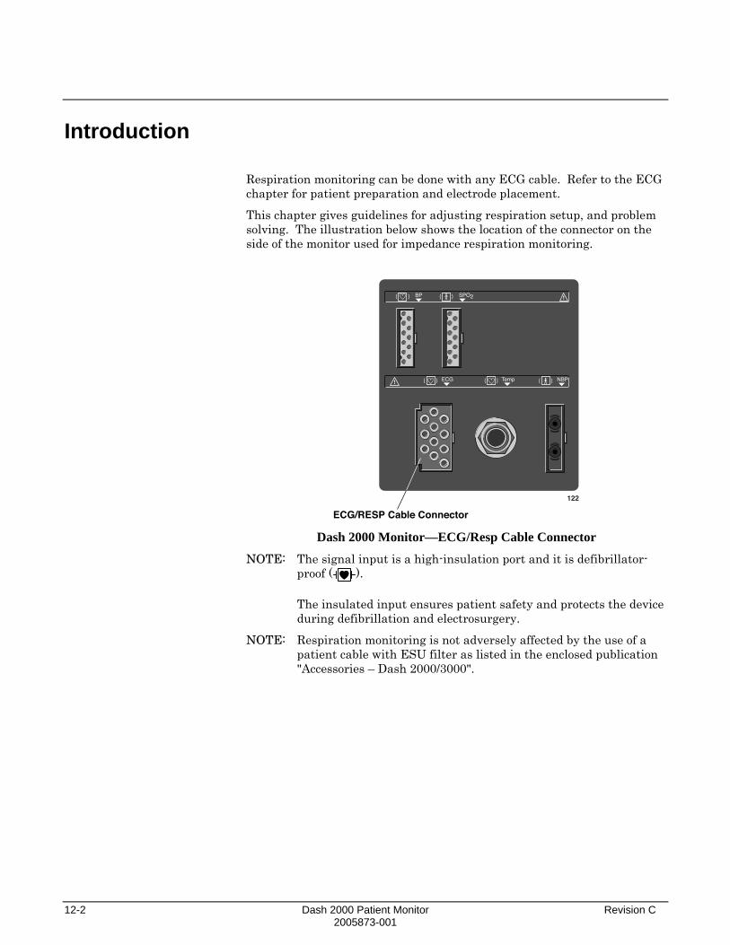
12-2 Dash 2000 Patient Monitor Revision C 2005873-001
Introduction
Respiration monitoring can be done with any ECG cable. Refer to the ECG chapter for patient preparation and electrode placement.
This chapter gives guidelines for adjusting respiration setup, and problem solving. The illustration below shows the location of the connector on the side of the monitor used for impedance respiration monitoring.
ECG/RESP Cable Connector
122
BP
ECG Temp
SPO2
NBP
Dash 2000 Monitor—ECG/Resp Cable Connector
NOTE: The signal input is a high-insulation port and it is defibrillator-proof ( ). The insulated input ensures patient safety and protects the device during defibrillation and electrosurgery.
NOTE: Respiration monitoring is not adversely affected by the use of a patient cable with ESU filter as listed in the enclosed publication "Accessories – Dash 2000/3000".
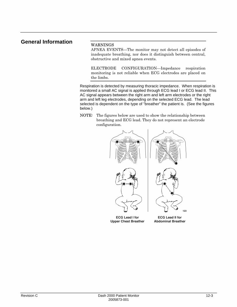
Revision C Dash 2000 Patient Monitor 12-3 2005873-001
General Information
WARNINGS APNEA EVENTS—The monitor may not detect all episodes of inadequate breathing, nor does it distinguish between central, obstructive and mixed apnea events.
ELECTRODE CONFIGURATION—Impedance respiration monitoring is not reliable when ECG electrodes are placed on the limbs.
Respiration is detected by measuring thoracic impedance. When respiration is monitored a small AC signal is applied through ECG lead I or ECG lead II. This AC signal appears between the right arm and left arm electrodes or the right arm and left leg electrodes, depending on the selected ECG lead. The lead selected is dependent on the type of ”breather” the patient is. (See the figures below.)
NOTE: The figures below are used to show the relationship between breathing and ECG lead. They do not represent an electrode configuration.
123
ECG Lead I forUpper Chest Breather
ECG Lead II forAbdominal Breather

12-4 Dash 2000 Patient Monitor Revision C 2005873-001
Checklist
When starting respiration monitoring, the monitor ”learns” the patient’s respiration pattern. Eight breaths are averaged and the average amplitude of the respiration waveform is found. Detection sensitivity is automatically set at 40% of the average amplitude.
NOTE: The message ”LEARNING” is displayed in the RR values window during this process.
Markers displayed on the waveform show this 40% detection range. One marker is at inspiration, the other at expiration. The detection sensitivity can be manually adjusted by using the SENSITIV option from the respiration menu.
The waveform size is also set automatically during the learning process, but may be adjusted if necessary.
NOTE: Respiration detection is not dependent on the size of the waveform. Size is for visual purposes only.
Even though the same electrodes are used for ECG and respiration monitoring, it is possible to get a lead fail message for respiration without one for ECG. The impedance may be too high for respiration detection, but the electrode is still good for ECG. (Refer to Smart-Lead Fail in the ECG Monitoring chapter.)
Since respiration monitoring is so closely linked with ECG monitoring, patient preparation and electrode placement are important. Please refer to the ECG Monitoring chapter for guidelines.
1. Electrodes have been placed on the patient following proper skin preparation.
2. Leadwires are attached to electrodes on the patient.
3. Leadwires are connected to patient cable and patient cable is connected to the monitor.
4. Respiration setup is adjusted, if necessary. Follow detailed procedures within this chapter.

Revision C Dash 2000 Patient Monitor 12-5 2005873-001
Respiration Monitoring Features
Respiration Information
When respiration monitoring is on, a labeled respiration waveform is displayed when the learning process is complete. (Refer to this section, General Information.) The label includes the ECG lead used to derive the respiration waveform, for example, RR II.
Numerics are displayed in the RR parameter window on the right side of the screen.
RR 55/ 520 S
II 20Breath Indicator
Lead Monitored
Limits
Respiration Rate
124 RR Parameter Window
The parameter window displays the current respiration rate and the ECG lead used to monitor respiration. A flashing breath indicator (lung symbol) is displayed with each breath detection. Alarm limits may be displayed for respiration rate and apnea.
The respiration monitoring features are found in the RR parameter menu. These features include lead, relearn, sensitivity, limits, size, and cardiac artifact alarm.

12-6 Dash 2000 Patient Monitor Revision C 2005873-001
Getting to the Respiration Menu
To display the Respiration Menu, use the Trim Knob control to select the RR parameter label. Remember, selecting with the Trim Knob control is a two-step process—rotate to highlight, then press to select.
NOTE: If the parameter label is not displayed, select PARAM ON/OFF option in the Monitor Setup Menu to turn respiration on. Then select the RR parameter label.
RR 55/ 520 S
II 20125
Selecting the RR Parameter Label The Respiration Menu is displayed at the bottom of the screen.
MAINMENU
LEAD:II
RELEARNRESP
SENSITIV:40 %
RESPLIMITS
SIZECARDIACARTIFACT:ON / OFF
126 Respiration Menu
With the Trim Knob control, you now can select any of the displayed options.
• LEAD—change the lead from which the respiration rate is derived.
• RELEARN RESP—tell the monitor to examine and relearn the patient’s respiration pattern.
• RESP LIMITS—display a new menu and an information window to adjust respiration rate and apnea alarm limits.
• SENSITIV—increase or decrease the sensitivity setting.
• CARDIAC ARTIFACT—turn the artifact alarm off and on.
• SIZE—displays the SIZE menu with the AUTO SIZE and MANUAL SIZE options. • AUTO SIZE—automatically size the respiration waveform to fit in a
predetermined area on the screen.
• MANUAL SIZE—manually increase or decrease the size of the respiration waveform.
Detailed information on each option is found in this chapter.

Revision C Dash 2000 Patient Monitor 12-7 2005873-001
Respiration Menu Options
Lead
Relearn Respiration
You have two choices for the respiration lead—lead I and lead II. This menu option, when selected, automatically switches the monitored lead for respiration. The label of the lead currently being monitored (I or II) appears in the menu option, in the lower left corner of the RR parameter window, and with the waveform label.
Changing leads automatically starts the relearn process.
NOTE: If you are monitoring with a fixed-lead 3-lead cable, respiration can only be obtained from the lead for which the cable is manufactured. For example, if your cable is a fixed lead II cable, you will see a ”LD I FAIL” message in the RR parameter window should you try to change the respiration lead.
A ”learning” process always takes place for a few seconds whenever respiration monitoring is started. If your patient’s breathing pattern changes after the initial learning process has taken place, it may be necessary to relearn. Select RELEARN RESP option from the respiration menu. This is a direct action menu option.
The message ”LEARNING” will be displayed in the RR values window. (There is no respiration rate displayed during the learning process.) When learning is complete, the message will clear and the respiration rate will be displayed.
NOTE: Sensitivity is reset at 40% and the waveform is automatically sized.

12-8 Dash 2000 Patient Monitor Revision C 2005873-001
Respiration Limits
This option provides an information window that shows the alarm limits for respiration rate and apnea. A new set of menu options is displayed to allow you to adjust these limits.
Follow this procedure:
1. Select RESP LIMITS option from the Respiration Menu. An information window is displayed on the screen and a new set of menu options is displayed in the menu area.
21-NOV-2000 16:27
II
DAK.BED 1
RESP LIMITS
RETURNRRRR-APNEA
UNITS#/minsec
LOW5
HIGH3020
MAINMENU
RESPLIMITS
>
128 RESPIRATION LIMITS Menu and Information Window
2. Rotate the Trim Knob control to move the pointer (>) through the list.
3. Press the Trim Knob control when the pointer is in front of the parameter for which you want to change default limits. The parameter label highlights.
4. Turn the Trim Knob control to highlight the low or high limit.
5. Press the Trim Knob control again and rotate to change value. Press the Trim Knob control to complete the change.
6. Rotate the Trim Knob control to highlight the parameter label and press to unhighlight.
7. Select RETURN when all changes are completed. The popup men and information window close.
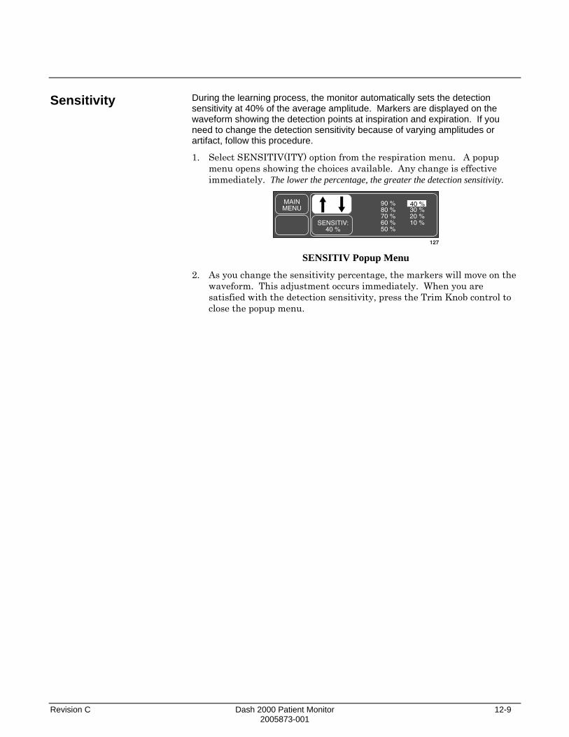
Revision C Dash 2000 Patient Monitor 12-9 2005873-001
Sensitivity
During the learning process, the monitor automatically sets the detection sensitivity at 40% of the average amplitude. Markers are displayed on the waveform showing the detection points at inspiration and expiration. If you need to change the detection sensitivity because of varying amplitudes or artifact, follow this procedure.
1. Select SENSITIV(ITY) option from the respiration menu. A popup menu opens showing the choices available. Any change is effective immediately. The lower the percentage, the greater the detection sensitivity.
MAINMENU
SENSITIV:40 %
90 %80 %70 %60 %50 %
40 %30 %20 %10 %
127
40 %
SENSITIV Popup Menu
2. As you change the sensitivity percentage, the markers will move on the waveform. This adjustment occurs immediately. When you are satisfied with the detection sensitivity, press the Trim Knob control to close the popup menu.

12-10 Dash 2000 Patient Monitor Revision C 2005873-001
Cardiac Artifact Alarm
The cardiac artifact alarm alerts you to the fact that the respiration rate is within 5% of the heart rate (over 30 consecutive breaths). If this happens, the respiration program may be counting heart beat artifact as respiration. The cardiac artifact alarm is an Advisory alarm—ARTIFACT is displayed in the RR values window, and a 1-beep tone sounds.
There is no adjustable limit for this alarm, but you can turn it off and on.
WARNING If the cardiac artifact alarm is turned off, apnea events may not be detected.
Select CARDIAC ARTIFACT option from the Respiration Menu to turn the alarm off and on. This is a direct action menu option.
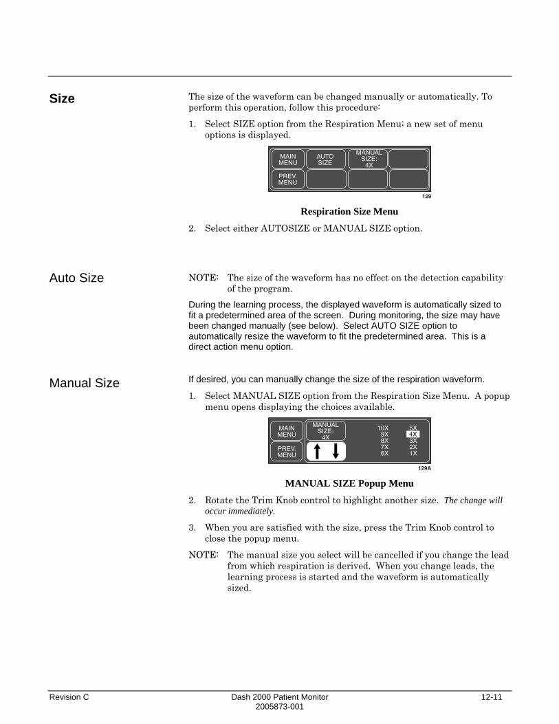
Revision C Dash 2000 Patient Monitor 12-11 2005873-001
Size
Auto Size
Manual Size
The size of the waveform can be changed manually or automatically. To perform this operation, follow this procedure:
1. Select SIZE option from the Respiration Menu; a new set of menu options is displayed.
MAINMENU
AUTOSIZE
MANUALSIZE:
4X
PREV.MENU
129 Respiration Size Menu
2. Select either AUTOSIZE or MANUAL SIZE option.
NOTE: The size of the waveform has no effect on the detection capability of the program.
During the learning process, the displayed waveform is automatically sized to fit a predetermined area of the screen. During monitoring, the size may have been changed manually (see below). Select AUTO SIZE option to automatically resize the waveform to fit the predetermined area. This is a direct action menu option.
If desired, you can manually change the size of the respiration waveform.
1. Select MANUAL SIZE option from the Respiration Size Menu. A popup menu opens displaying the choices available.
MAINMENU
MANUALSIZE:
4X
10X9X8X7X6X
5X
3X2X1X
PREV.MENU
129A
4X
MANUAL SIZE Popup Menu
2. Rotate the Trim Knob control to highlight another size. The change will occur immediately.
3. When you are satisfied with the size, press the Trim Knob control to close the popup menu.
NOTE: The manual size you select will be cancelled if you change the lead from which respiration is derived. When you change leads, the learning process is started and the waveform is automatically sized.
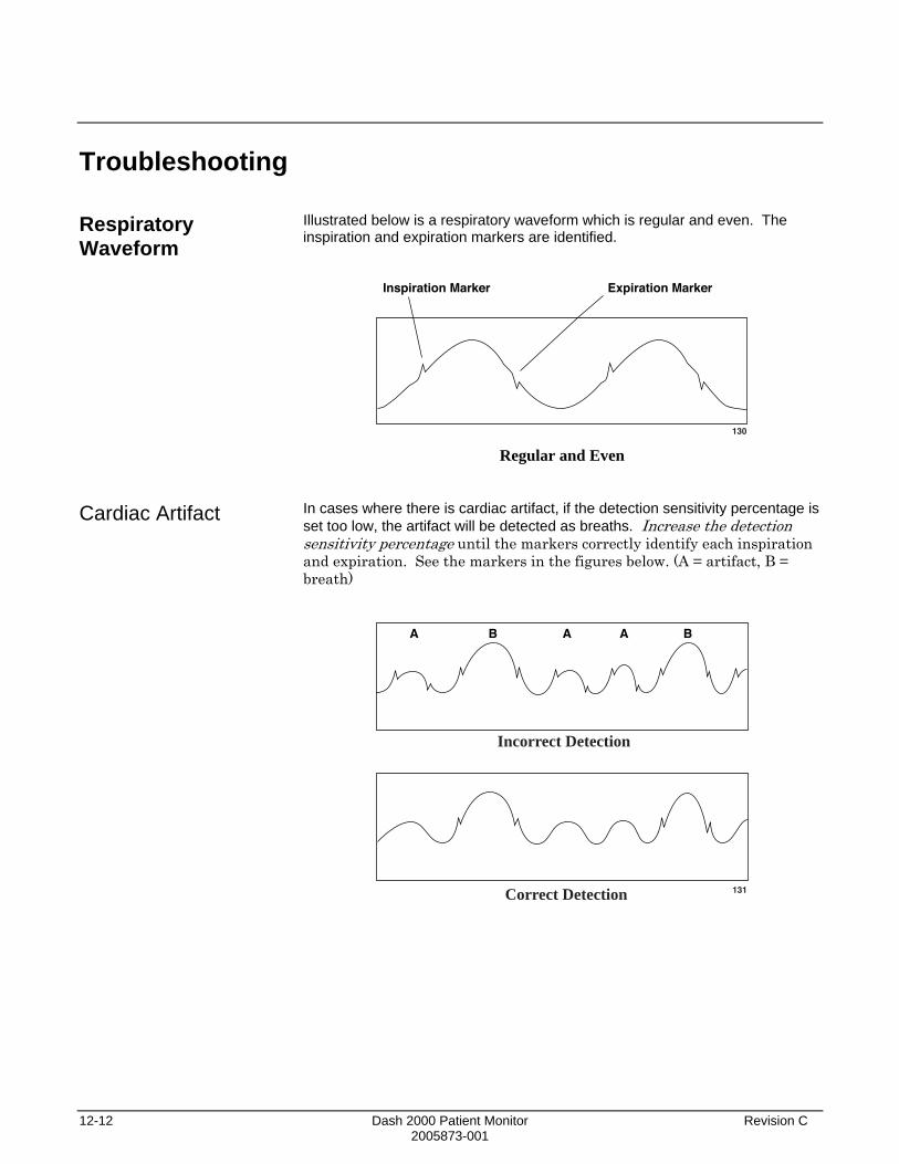
12-12 Dash 2000 Patient Monitor Revision C 2005873-001
Troubleshooting
Respiratory Waveform Cardiac Artifact
Illustrated below is a respiratory waveform which is regular and even. The inspiration and expiration markers are identified.
Inspiration Marker
130
Expiration Marker
Regular and Even
In cases where there is cardiac artifact, if the detection sensitivity percentage is set too low, the artifact will be detected as breaths. Increase the detection sensitivity percentage until the markers correctly identify each inspiration and expiration. See the markers in the figures below. (A = artifact, B = breath)
A B A A B
131
Incorrect Detection
Correct Detection

Revision C Dash 2000 Patient Monitor 12-13 2005873-001
Varying Amplitudes
Messages
Some waveforms may show a combination of shallow and deep breaths. If the detection sensitivity percentage is set too high, the shallow breaths will not be detected. Decrease the detection sensitivity percentage until the markers correctly identify each inspiration and expiration. See the markers in the figures below. (B = breath)
B B B B B
132
Incorrect Detection
Correct Detection
Below is a list of all the messages which may be displayed in the RR parameter window during respiration monitoring. What each of these messages mean as well as action to take is included. These messages may appear in abbreviated form if the parameter window is sized smaller due to the number of parameters being monitored. The abbreviated form, if there is one, is shown in parenthesis.
LEARNING
The monitor takes approximately 8 breaths to learn the patient’s respiration pattern before displaying a respiration value. Learning automatically occurs whenever respiration is turned on and when the lead from which respiration is determined is switched.
APNEA
CHECK THE PATIENT. This is an alarm condition which requires action. Breathing has not been detected for a predetermined period of seconds. If necessary, the apnea limit can be changed. Refer to page 12-8.
ARTIFACT
CHECK THE PATIENT. This is an alarm condition which requires action. The monitor is unable to successfully determine respiration. If it is determined that patient condition is not the cause, it may be necessary to reprep the patient’s skin and change the electrodes to resume monitoring of respiration.

12-14 Dash 2000 Patient Monitor Revision C 2005873-001
LD I FAIL or LD II FAIL
CHECK THE PATIENT. This is an alarm condition which requires action. The lead monitoring respiration has failed. You can manually switch respiration detection to the other lead (refer to page 12-7). Or it may be necessary to reprep the patient’s skin and change the electrodes.
LEADS FAIL (LDS FAIL)
CHECK THE PATIENT. This is an alarm condition which requires action. It may be necessary to reprep the patient’s skin and change the electrodes.

Revision C Dash 2000 Patient Monitor 13-1 2005873-001
13 TEMPERATURE Introduction....................................................................................13-2
Checklist....................................................................................13-2
Temperature Monitoring Features...............................................13-3 Temperature Information ........................................................13-3 Getting to the Temperature Menu ..........................................13-4
Temperature Menu Options..........................................................13-5 Units ..........................................................................................13-5 TP Limits...................................................................................13-5
Troubleshooting .............................................................................13-6 Messages....................................................................................13-6
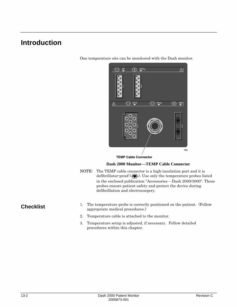
13-2 Dash 2000 Patient Monitor Revision C 2005873-001
Introduction
Checklist
One temperature site can be monitored with the Dash monitor.
TEMP Cable Connector
134
BP
ECG Temp
SPO2
NBP
Dash 2000 Monitor—TEMP Cable Connector
NOTE: The TEMP cable connector is a high-insulation port and it is defibrillator-proof ( ). Use only the temperature probes listed in the enclosed publication "Accessories – Dash 2000/3000". These probes ensure patient safety and protect the device during defibrillation and electrosurgery.
1. The temperature probe is correctly positioned on the patient. (Follow appropriate medical procedures.)
2. Temperature cable is attached to the monitor.
3. Temperature setup is adjusted, if necessary. Follow detailed procedures within this chapter.

Revision C Dash 2000 Patient Monitor 13-3 2005873-001
Temperature Monitoring Features
Temperature Information
Temperature monitoring provides numerical information only—no waveform. As with other parameters, numerics are displayed in the temperature (TP) parameter window on the right side of the screen.
TP 42.0/ 30.0˚ C
37.8
Temp Limits
Temp Value
Units
135 Temperature Parameter Window
The parameter window displays the current temperature values with the unit of measurement.
You can monitor a patient’s temperature at multiple sites. Both internal and external temperature sensors may be used. The monitor calculates the monitored temperature and displays its value on the screen.
The monitor is compatible with YSI series 400 probes listed in the enclosed publication "Accessories – Dash 2000/3000".
The temperature cable is plugged into the TEMP cable connector on the monitor. The temperature monitoring features are found in the Temperature Parameter Menu.
WARNINGS When the probe becomes disconnected, the temperature monitoring function is disabled, but no alarm is submitted. In order to ensure reliable patient monitoring, the proper application of the probe and the connection must be checked at regular intervals.
Do not route cables in a way that they may present a stumbling hazard.
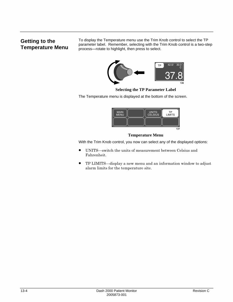
13-4 Dash 2000 Patient Monitor Revision C 2005873-001
Getting to the Temperature Menu
To display the Temperature menu use the Trim Knob control to select the TP parameter label. Remember, selecting with the Trim Knob control is a two-step process—rotate to highlight, then press to select.
TP 42.0/ 30.0 C
37.8136
Selecting the TP Parameter Label The Temperature menu is displayed at the bottom of the screen.
MAINMENU
UNITS:CELSIUS
TPLIMITS
137 Temperature Menu
With the Trim Knob control, you now can select any of the displayed options:
• UNITS—switch the units of measurement between Celsius and Fahrenheit.
• TP LIMITS—display a new menu and an information window to adjust alarm limits for the temperature site.

Revision C Dash 2000 Patient Monitor 13-5 2005873-001
Temperature Menu Options
Units
TP Limits
This direct action menu option switches the units of measure between Celsius (C) and Fahrenheit (F).
A new set of menu options is displayed to allow you to adjust these limits.
Follow this procedure:
1. Select TP LIMITS option from the Temperature Menu. An information window is displayed on the screen and a new set of menu options is displayed in the menu area.
21-NOV-2000 16:27
II
DAK.BED 1
TP LIMITS
RETURNTP
UNITS C
LOW00.0
HIGH42.0
MAINMENU
TPLIMITS
>
138 TP LIMITS Menu and Information Window
2. Rotate the Trim Knob control to move the pointer (>) through the list.
3. Press the Trim Knob control when the pointer is in front of TP. The parameter label highlights.
4. Turn the Trim Knob control to highlight the low or high limit.
5. Press the Trim Knob control again and rotate to change value. Press the Trim Knob control to complete the change.
6. Rotate the Trim Knob control to highlight the parameter label and press to unhighlight.
7. Select RETURN when all changes are completed. The popup men and information window close.

13-6 Dash 2000 Patient Monitor Revision C 2005873-001
Troubleshooting
Messages
If you experience some problems with temperature monitoring, one of the following messages may be displayed in the TP parameter window:
CHECK
There is a 0.1 oC deviation between the temperature value and the internal calibration. No temperature value will be displayed. Service on the monitor is required.
CAL FAIL
There is a 1 oC deviation between the temperature value sensed and the internal calibration. No temperature value will be displayed. Service on the monitor is required.
SENSOR
The temperature sensor has failed.

Revision C Dash 2000 Patient Monitor 14-1 2005873-001
14 APPENDICES Defib Sync/Analog Output.............................................................14-2
ECG Acquisition Modules ........................................................14-2
Abbreviations and Symbols...........................................................14-3 Abbreviations ............................................................................14-3 Symbols......................................................................................14-9
Software Packages .......................................................................14-10
Factory Defaults—Adult-ICU Mode ...........................................14-11
Factory Defaults—Neonatal-ICU Mode .....................................14-15
Factory Defaults—Operating Room Mode .................................14-19
Minimum and Maximum Limits (Default Mode) ......................14-23
Technical Specifications ..............................................................14-24 Display.....................................................................................14-24 Controls ...................................................................................14-24 Processing................................................................................14-24 Alarms .....................................................................................14-25 ECG..........................................................................................14-25 Respiration ..............................................................................14-26 Temperature (TEMP) .............................................................14-27 Invasive Blood Pressure (BP).................................................14-27 Pulse Oximetry (SpO2)...........................................................14-28 Non-invasive Blood Pressure (NBP)......................................14-28 Paper Recorder........................................................................14-30 Analog Output.........................................................................14-30 Defibrillator Synchronization Pulse ......................................14-30 Environmental Specifications ................................................14-31 Physical Specifications ...........................................................14-32 Certification ............................................................................14-32 Warranty .................................................................................14-32

14-2 Dash 2000 Patient Monitor Revision C 2005873-001
Defib Sync/Analog Output
ECG Acquisition Modules
The configuration for the analog output from the ECG acquisition modules is detailed below. Analog output is obtained through the Defib Sync connector on the rear of the monitor.
ECG ANALOG OUTPUT: Top displayed lead including augmented leads. If pace is on there is an enhanced pacer pulse (5 volts at 2 milliseconds) when pacemaker triggering is detected.
In the event of a LEAD FAIL, refer to the following:
Lead Failed AHA Label IEC Label ECG Analog Out
Right arm RL R III
Left arm LA L II
Left leg LL F I
Chest V C II
Right leg RL N Buzz*
*A right leg lead fail causes an all LEADS FAIL on the screen and a buzz is output.
NOTES:
1. All ECG outputs are 1 volt per millivolt referred to input.
2. In single lead mode, if the specified lead is not available, a buzz will be output.
DIGITAL SYNCHRONIZATION OUTPUT: A digital sync output is available with a return marker. For the technical specifications refer to appendix Technical Specifications, section Analog Out and Defibrillator Synchronization Pulse.
Revision C Dash 2000 Patient Monitor 14-3 2005873-001
Abbreviations and Symbols
Abbreviations
Abbreviations and symbols which you may encounter while reading this manual or using the monitor are listed below with their meaning.
A A amps AaDO2 alveolar arterial oxygen gradient ABG arterial blood gas AC alternating current ACCV accelerated ventricular ACC VENT accelerated ventricular ADT adult AHA American Heart Association ANT anterior AO2 (aO2) arterial oxygen saturation AR argon ARR arrhythmia ART arterial ASYS asystole Auto, AUTO automatic a-v02 arterial venous oxygen content difference AVF left foot augmented lead AVG average AVL left arm augmented lead AVR right arm augmented lead
B BE base excess BGMY bigeminy BP blood pressure BPM beats per minute BRAD bradycardia BSA body surface area BT blood temperature
C C Celsius CAL calibration CALC calculation CALCS calculations CaO2 arterial oxygen content CARD cardiac CC computation constant cc, CC cubic centimeter CCU critical care unit CEd effective dynamic compliance CH channel

14-4 Dash 2000 Patient Monitor Revision C 2005873-001
CI cardiac index cm, CM centimeter CO cardiac output, carbon monoxide CO2 carbon dioxide COHb carboxyhemoglobin COMM communication CP cardiopulmonary CPLT couplet CPP cerebral perfusion pressure CS central station CvO2 mixed venous oxygen content difference CVP central venous pressure
D D diastolic DC direct current DDW Direct Digital Writer DEFIB, Defib defibrillator DES desflurane DIA diastolic DISCH discharge dyn dyne
E E expired ea-vO2 estimated arterial venous oxygen content difference eCaO2 estimated arterial oxygen content ECG electrocardiograph eCvO2 estimated mixed venous oxygen content eg for example ENF enflurane eO2CI estimated oxygen consumption eO2DI estimated oxygen delivery eO2R estimated oxygen extraction ratio eQs/Qt estimated shunt fraction Esopho esophageal ESU electrosurgical cautery unit et al and others EtCO2, ETCO2 end-tidal carbon dioxide ETO Ethylene Oxide EX, Exp expired
F F Fahrenheit FEM femoral FiO2 fraction of inspired oxygen FR French (catheter size)

Revision C Dash 2000 Patient Monitor 14-5 2005873-001
G g gr GTT/CC, gtt/cc drops per cubic centimeter
H HAL halothane Hb hemoglobin HbO2 oxyhemoglobin HCO3 bicarbonate HE helium Hgb hemoglobin HR heart rate, hour HT height Hz hertz
I I inspired IABP intra-aortic balloon pump ICP intracranial pressure ICU intensive care unit ie that is IEEE Institute of Electrial and Electronics Engineers IEC International Electrotechnical Commission IN inspired Inc incorporated INF infusion, inferior INIT initialization Inj, INJECT injectate Insp inspired IRRG irregular ISO isoflurane ISU inlet select unit IT injectate temperature IV intravenous
K kg, KG kilogram kPa kilopascal
L L liter, left LA left arm, left atrial LAT lateral LBS pounds LCD liquid crystal display LD lead LED light emitting diode LL left leg LVSWI left ventricular stroke work index

14-6 Dash 2000 Patient Monitor Revision C 2005873-001
M M mean, minute m meter MAP mean arterial pressure MAWP mean airway pressure MCG micrograms MetHb methemoglobin MG milligrams MIN, min minute mL milliliter MM, mm millimeters MM/S millimeters per second MMHG, mmHg millimeters of mercury MRI magnetic resonance image MTR motor MUNITS milliunits mV millivolt MV minute volume
N N2 nitrogen N20 nitrous oxide NBP noninvasive blood pressure NC non-capture NEO, Neo neonatal NRT non real-time NS non-sense
O O2 oxygen O2CI oxygen consumption index O2D1 oxygen delivery index O2R oxygen extraction ratio OR operating room
P PA pulmonary artery PaCO2 partial pressure of carbon dioxide in arterial blood PAD pulmonary artery diastolic Pa/FiO2 oxygenation ratio PAM pulmonary artery mean pressure PaO2 partial pressure of oxygen in arterial blood PAO2 alveolar pressure PAUS pause PAW pulmonary artery wedge pressure PBAR barometric pressure PCO2 partial pressure of arterial carbon dioxide PEAKP end inspiratory pressure PED pediatric

Revision C Dash 2000 Patient Monitor 14-7 2005873-001
PEEP positive end expiratory pressure pH hydrogen ion concentration PIP peak inspiratory pressure PO2 partial pressure of arterial oxygen PPLAT plateau pressure PT-RR patient respiration rate PULM pulmonary PVC premature ventricular complex PvO2 partial pressure of oxygen in mixed venous blood PVR pulmonary vascular resistance PVRI pulmonary vascular resistance index PWR power
Q QA quality assurance QRS interval of ventricular depolarization Qs/Qt shunt fraction QTY quantity
R R rate, right RA right arm, right atrial RESP respiration RHb reduced hemoglobin RHY rhythm RL right leg RM respiratory mechanics RT A.LM remote alarm RMTVID remote video RR respiration rate RTFC artifact RVSWI right ventricular stroke work index
S S systolic Sa02 arterial oxygen saturation sec second SOL solution SP special SPEC spectrometer SpO2 arterial oxygen saturation from pulse oximetry SUM summation SV stroke volume SvO2 mixed venous oxygen saturation SVR systemic vascular resistance SVRI systemic vascular resistance index SYNC, Sync synchronization SYS systolic

14-8 Dash 2000 Patient Monitor Revision C 2005873-001
T Tl temperature site 1 T2 temperature site 2 TACH tachycardia Temp, TEMP temperature TGMY trigeminy TP temperature TV tidal volume
U UAC umbilical artery catheter UVC umbilical venous catheter
V V precordial lead V volt VAC volts AC (alternating current) VBRADY ventricular bradycardia VBRD ventricular bradycardia VENT ventilator V-Fib, V-FIB ventricular fibrillation VID video VNT ventilator VT ventricular tachycardia VTAC ventricular tachycardia V-Tach, V-TACH ventricular tachycardia VOL volume
W WT weight
X X multiplier when used with a number (2X)
denotes invalid data when used in place of a value on the display

Revision C Dash 2000 Patient Monitor 14-9 2005873-001
Symbols 12SL 12-lead ECG analysis & and ° degree(s) > greater than < less than - minus # number % percent ± plus or minus

14-10 Dash 2000 Patient Monitor Revision C 2005873-001
Software Packages
There is an invasive pressure software package available for the Dash 2000 patient monitor. This package can be activated by entering a password in the service mode.

Revision C Dash 2000 Patient Monitor 14-11 2005873-001
Factory Defaults—Adult-ICU Mode
Following are the factory-set monitor defaults for the Adult-ICU Mode. You can change these using the Monitor Defaults feature. Monitor defaults are recalled upon discharge. Refer to the Monitor Setup chapter.
Arrhythmia Alarm Levels
Crisis Warning Advisory Message
Asystole VFib/VTac V Tach
Parameter Alarm Levels
Crisis Warning Advisory Message
HR PA ART NBP SPO2 FEM UAC CVP RA UVC LA ICP SP ART Rate RR Resp Apnea
SPO2 Rate TP FEM Rate UAC Rate

14-12 Dash 2000 Patient Monitor Revision C 2005873-001
Parameter Limits
Low High
HR 50 150
NBP-S 80 200
NBP-D 20 120
NBP-M 40 140
ART-S 80 200
ART-D 20 120
ART-M 40 140
ART-R 50 150
FEM-S 80 200
FEM-D 20 120
FEM-M 40 140
FEM-R 50 150
UAC-S 80 200
UAC-D 20 120
UAC-M 40 140
UAC-R 50 150
PA-S -99 350
PA-D -99 350
PA-M -99 350
CVP -99 350
RA -99 350
UVC -99 350
LA -99 350
ICP -99 350
SP -99 350
SpO2 90 105
SpO2-R 50 150
RR 5 30
RR-Apnea - 20
TP 30.0°C/86.0°F 42.0°C/107.6°F

Revision C Dash 2000 Patient Monitor 14-13 2005873-001
Display Defaults Patient Age Adult
Color Format* Transducer
Background** black
Primary ECG II
Arrhythmia On
Detect Pace Off
Arterial Rate On
Lead Analysis Multi-Lead
Graph Waveform 2 ART
Graph Waveform 3 Off
Alarm Graph On
Timed Graph Continuous
ART Disconnect On
Smart BP On
Arterial Scale 160
PA Scale 60
CVP-RA-UVC Scale 30
LA Scale 30
ICP Scale 30
SP Scale 160
NBP Auto Off
Adult Cuff Pressure Auto
PED Cuff Pressure Auto
NEO Cuff Pressure Auto
NBP Cuff Size Adult
RR Parameter Off
RR Lead II
View on Alarm Off
VOA Broadcast Off
Remote Alarm Level Crisis
Alarm Volume 70%
Silence Alarm Normal
QRS Volume Off
Rate Volume Off
ECG Leads Fail Sys Warning
SPO2 Probe Off Sys Warning
Display Limits On
Display Units Off
Units for Height cm
Units for Weight kg
Temperature Units °C
NBP Limits Type Systolic
Arterial Limits Type Systolic
PA Limits Type Diastolic
Menu Timeout 5 minutes
ECG Filter Monitoring
BP Filter 12 Hz
QRS Width Normal
Discharge Alert Off
* color display
** monochrome display

14-14 Dash 2000 Patient Monitor Revision C 2005873-001
Parameter Priority Defaults
The following parameters, when monitored, will always appear in parameter windows at the right side of the display. Parameter 1 ECG
Parameter 2 SPO2
Parameter 3 RR
The highlighted parameters below appear in parameter windows at the bottom of the display only when there is no room at the side.
NBP UVC
ART LA
FEM ICP
UAC SP
PA SPO2
CVP RR
RA TP

Revision C Dash 2000 Patient Monitor 14-15 2005873-001
Factory Defaults—Neonatal-ICU Mode
Following are the factory-set monitor defaults for the Neonatal-ICU Mode. You can change these using the Monitor Defaults feature. Monitor defaults are recalled upon discharge. Refer to the Monitor Setup chapter.
Arrhythmia Alarm Levels
Crisis Warning Advisory Message
Asystole VFib/VTac V Tach
Parameter Alarm Levels
Crisis Warning Advisory Message
Resp Apnea
HR UAC UVC SPO2 NBP ART FEM PA CVP RA LA ICP SP UAC Rate RR SPO2 Rate ART Rate FEM Rate TP

14-16 Dash 2000 Patient Monitor Revision C 2005873-001
Parameter Limits
Low High
HR 90 200
NBP-S 40 100
NBP-D 20 60
NBP-M 30 70
ART-S 40 100
ART-D 20 60
ART-M 30 70
ART-R 90 200
FEM-S 40 100
FEM-D 20 60
FEM-M 30 70
FEM-R 90 200
UAC-S 40 100
UAC-D 20 60
UAC-M 30 70
UAC-R 90 200
PA-S -99 350
PA-D -99 350
PA-M -99 350
CVP -99 350
RA -99 350
UVC -99 350
LA -99 350
ICP -99 350
SP -99 350
SpO2 88 100
SpO2-R 90 200
RR 15 100
RR-Apnea - 15
TP 30.0°C/86.0°F 42.0°C/107.6°F

Revision C Dash 2000 Patient Monitor 14-17 2005873-001
Display Defaults Patient Age 0-2 years
Color Format* Transducer
Background** Black
Primary ECG II
Arrhythmia On
Detect Pace Off
Arterial Rate On
Lead Analysis Multi-Lead
Graph Waveform 2 ART
Graph Waveform 3 RR
Alarm Graph Off
Timed Graph Continuous
Arterial Scale 100
PA Scale 60
CVP-RA-UVC Scale 30
LA Scale 30
ICP Scale 30
SP Scale 160
NBP Auto Off
Adult Cuff Pressure Auto
PED Cuff Pressure Auto
NEO Cuff Pressure Auto
NBP Cuff Size Neonatal
RR Parameter On
RR Lead II
View on Alarm Off
VOA Broadcast Off
Remote Alarm Level Crisis
Alarm Volume 70%
Silence Alarm Normal
QRS Volume Off
Rate Volume Off
ECG Leads Fail Sys Warning
SPO2 Probe Off Sys Warning
Display Limits On
Display Units Off
Units for Height cm
Units for Weight kg
Temperature Units °C
NBP Limits Type Systolic
Arterial Limits Type Systolic
PA Limits Type Diastolic
Menu Timeout 5 minutes
ECG Filter Monitoring
BP Filter 12 Hz
QRS Width Narrow
Discharge Alert Off
* color display
** monochrome display
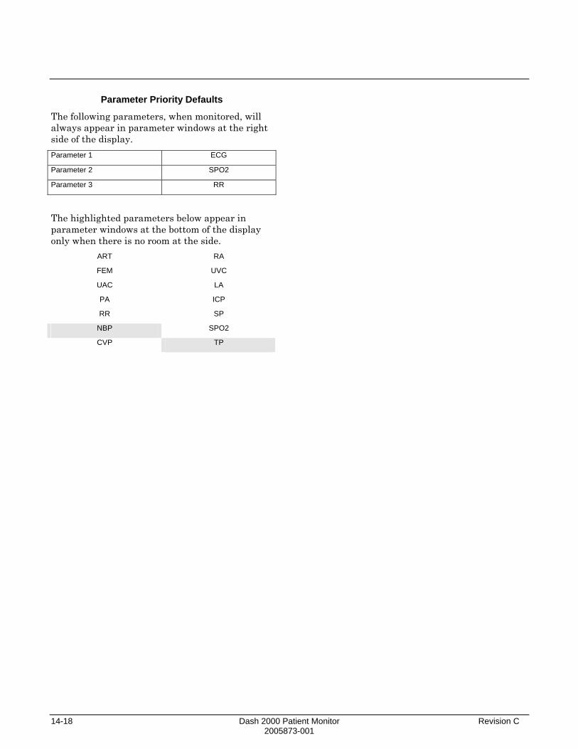
14-18 Dash 2000 Patient Monitor Revision C 2005873-001
Parameter Priority Defaults
The following parameters, when monitored, will always appear in parameter windows at the right side of the display. Parameter 1 ECG
Parameter 2 SPO2
Parameter 3 RR
The highlighted parameters below appear in parameter windows at the bottom of the display only when there is no room at the side.
ART RA
FEM UVC
UAC LA
PA ICP
RR SP
NBP SPO2
CVP TP
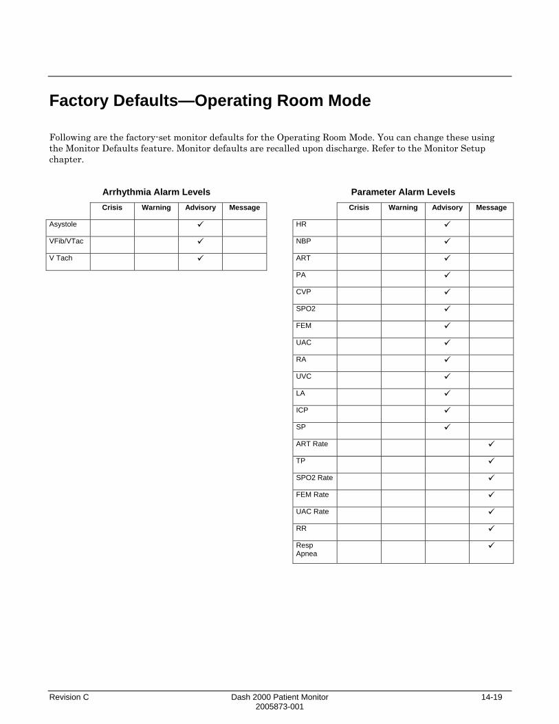
Revision C Dash 2000 Patient Monitor 14-19 2005873-001
Factory Defaults—Operating Room Mode
Following are the factory-set monitor defaults for the Operating Room Mode. You can change these using the Monitor Defaults feature. Monitor defaults are recalled upon discharge. Refer to the Monitor Setup chapter.
Arrhythmia Alarm Levels
Crisis Warning Advisory Message
Asystole VFib/VTac V Tach
Parameter Alarm Levels
Crisis Warning Advisory Message
HR NBP ART PA CVP SPO2 FEM UAC RA UVC LA ICP SP ART Rate TP SPO2 Rate FEM Rate UAC Rate RR Resp Apnea

14-20 Dash 2000 Patient Monitor Revision C 2005873-001
Parameter Limits
Low High
HR -1 150
NBP-S 40 200
NBP-D 20 120
NBP-M 40 140
ART-S 40 200
ART-D 20 120
ART-M 40 140
ART-R -1 150
FEM-S 40 200
FEM-D 20 120
FEM-M 40 140
FEM-R -1 150
UAC-S 40 200
UAC-D 20 120
UAC-M 40 140
UAC-R -1 150
PA-S -99 350
PA-D -99 350
PA-M -99 350
CVP -99 350
RA -99 350
UVC -99 350
LA -99 350
ICP -99 350
SP -99 350
SpO2 90 105
SpO2-R -1 150
RR 1 200
RR-Apnea - 20
TP 0.0°C/32.0°F 42.0°C/107.6°F

Revision C Dash 2000 Patient Monitor 14-21 2005873-001
Display Defaults Patient Age Adult
Color Format* Transducer
Background** Black
Primary ECG II
Arrhythmia Off
Detect Pace Off
Arterial Rate On
Lead Analysis Multi-Lead
Graph Waveform 2 ART
Graph Waveform 3 Off
Alarm Graph Off
Timed Graph 20 seconds
ART Disconnect Off
Smart BP On
Arterial Scale 160
PA Scale 60
CVP-RA-UVC Scale 30
LA Scale 30
ICP Scale 30
SP Scale 160
NBP Auto Off
Adult Cuff Pressure Auto
PED Cuff Pressure Auto
NEO Cuff Pressure Auto
NBP Cuff Size Adult
RR Parameter Off
RR Lead II
View on Alarm Off
VOA Broadcast Off
Remote Alarm Level Crisis
Alarm Volume 40%
Silence Alarm Normal
QRS Volume Off
Rate Volume 40%
ECG Leads Fail Sys Advisory
SPO2 Probe Off Sys Warning
Display Limits Off
Display Units Off
Units for Height cm
Units for Weight kg
Temperature Units °C
NBP Limits Type Systolic
Arterial Limits Type Systolic
PA Limits Type Diastolic
Menu Timeout 5 minutes
ECG Filter Moderate
BP Filter 12 Hz
QRS Width Normal
Discharge Alert Off
* color display
** monochrome display

14-22 Dash 2000 Patient Monitor Revision C 2005873-001
Parameter Priority Defaults
The following parameters, when monitored, will always appear in parameter windows at the right side of the display. Parameter 1 ECG
Parameter 2 SPO2
Parameter 3 RR
The highlighted parameters below appear in parameter windows at the bottom of the display only when there is no room at the side.
SPO2 CVP
TP RA
NBP UVC
ART LA
FEM ICP
UAC SP
PA RR

Revision C Dash 2000 Patient Monitor 14-23 2005873-001
Minimum and Maximum Limits (Default Mode)
Parameter Low Limits
Min Max
HR -1 299
NBP-S -99 349
NBP-D -99 349
NBP-M -99 349
ART-S -99 349
ART-D -99 349
ART-M -99 349
ART-R -1 299
FEM-S -99 349
FEM-D -99 349
FEM-M -99 349
FEM-R -1 299
UAC-S -99 349
UAC-D -99 349
UAC-M -99 349
UAC-R -1 299
PA-S -99 349
PA-D -99 349
PA-M -99 349
CVP -99 349
RA -99 349
UVC -99 349
LA -99 349
ICP -99 349
SP -99 349
SpO2 0 104
SpO2-R -1 299
RR 1 199
RR-Apnea - -
TP -1.0 °C/30.2 °F 46.9 °C/116.5 °F
High Limits
Min Max
0 300
-98 350
-98 350
-98 350
-98 350
-98 350
-98 350
0 300
-98 350
-98 350
-98 350
0 300
-98 350
-98 350
-98 350
0 300
-98 350
-98 350
-98 350
-98 350
-98 350
-98 350
-98 350
-98 350
-98 350
1 105
0 300
2 200
3 30
-0.9°C/30.3°F 47.0°C/116.6°F
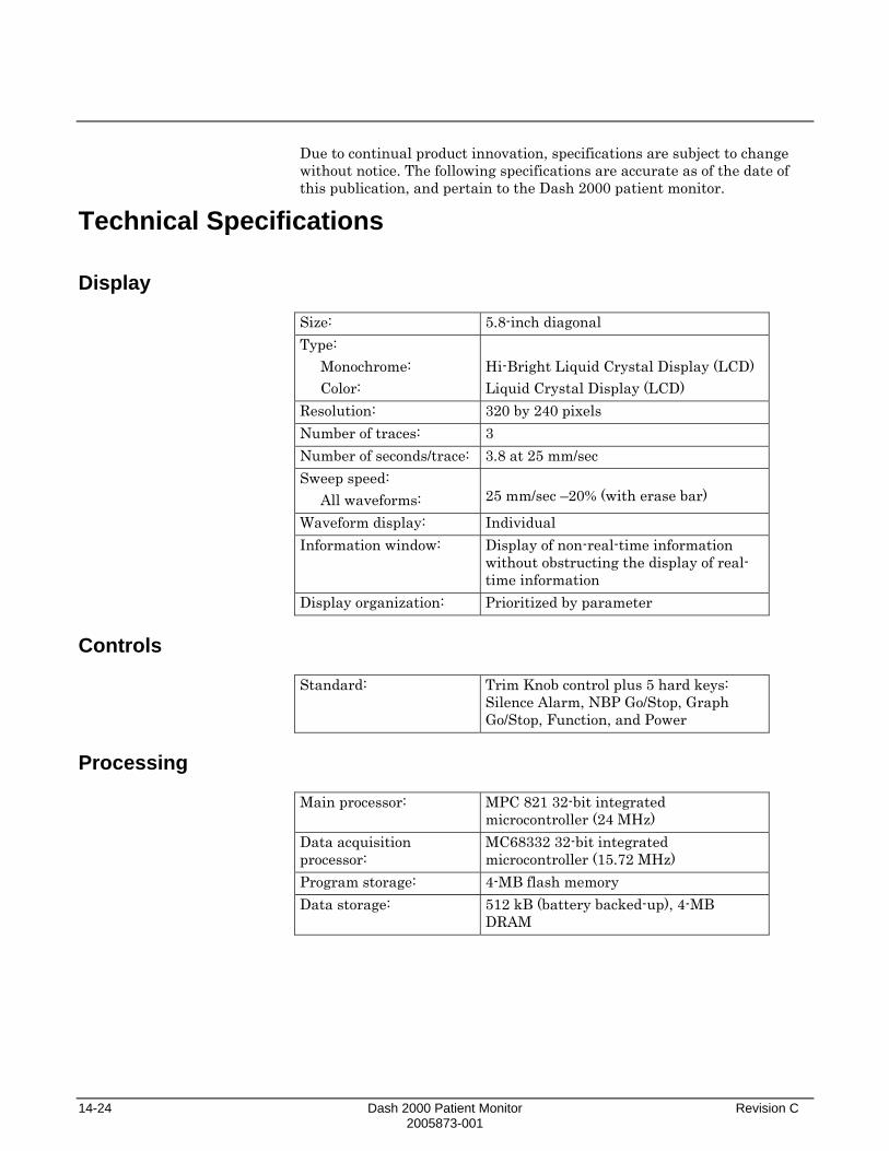
14-24 Dash 2000 Patient Monitor Revision C 2005873-001
Due to continual product innovation, specifications are subject to change without notice. The following specifications are accurate as of the date of this publication, and pertain to the Dash 2000 patient monitor.
Technical Specifications
Display Size: 5.8-inch diagonal Type:
Monochrome: Color:
Hi-Bright Liquid Crystal Display (LCD) Liquid Crystal Display (LCD)
Resolution: 320 by 240 pixels Number of traces: 3 Number of seconds/trace: 3.8 at 25 mm/sec Sweep speed:
All waveforms: 25 mm/sec –20% (with erase bar)
Waveform display: Individual Information window: Display of non-real-time information
without obstructing the display of real-time information
Display organization: Prioritized by parameter
Controls
Standard: Trim Knob control plus 5 hard keys:
Silence Alarm, NBP Go/Stop, Graph Go/Stop, Function, and Power
Processing
Main processor: MPC 821 32-bit integrated
microcontroller (24 MHz) Data acquisition processor:
MC68332 32-bit integrated microcontroller (15.72 MHz)
Program storage: 4-MB flash memory Data storage: 512 kB (battery backed-up), 4-MB
DRAM

Revision C Dash 2000 Patient Monitor 14-25 2005873-001
Alarms
Classification: 4 levels—Crisis, Warning, Advisory, and
Message Notification: Audible and visual Setting: Default and individual Silencing: 1 minute, current alarm only Pause: 5 minutes (adult); 3 minutes (neonatal);
5, 15 minutes, permanent (OR mode) Volume: Default 70%, 70 dB measured at 1 m
ECG
Standard leads available: I, II, III, V, aVR, aVL, and aVF Leads analyzed simultaneously:
I, II, III, and V (multi-lead mode)
Lead fail: Identifies failed lead Alarms: User selectable upper and lower heart
rate limits Input specifications:
Voltage range: QRS detection: Signal width: Heart rate range: Accuracy: Response time to change in heart rate Heart rate update: Input impedance:
Common mode: Differential:
Tall T-wave rejection amplitude:
±0.5 mV to ±5 mV amplitude 0.5 to 5 mV with size 2x or 4x below 1 mV and with QRS time duration Adult ICU 70 to 120 ms Neonatal ICU 40 to 80 ms 40 ms to 120 ms (Q to S) 30 to 300 BPM ±1% or ±1 BPM, whichever is greater 12 s ±2 s (HR averaging) 2 s >10 MOhms at 50/60 Hz >2.5 MOhms from dc to 60 Hz 1.2 mV max.
Output specifications: Frequency response: Display:
Diagnostic: Monitoring: Moderate: Maximum:
0.05 to 120 Hz 0.05 to 40 Hz 0.05 to 25 Hz
5 to 25 Hz

14-26 Dash 2000 Patient Monitor Revision C 2005873-001
Output specs (contd.):
Paper Recorder: Diagnostic: Monitoring: Moderate: Maximum:
Common mode rejection: Linearity deviation: Noise: Leads off sensing:
0.05 to 100 Hz 0.05 to 40 Hz 0.05 to 25 Hz
5 to 25 Hz 90 dB minimum at 50 Hz or 60 Hz ±3% <30 µV RTI (referred to input) For each electrode 1.25 V/62 MOhms referred to RL
Pacemaker detection/rejection:
Input voltage range: Input pulse width: Rise time: Over/under shoot: Baseline drift:
±2 mV to ±700 mV 0.1 to 2 ms 10 ms to 100 µs 2 mV (max.) with Diagnostic or Monitor filter setting and size 1x or 0.5x <0.5 mV/hour with a ±700-mV, 2-ms pacemaker pulse applied
Time to alarm: for tachycardia: for cardiac standstill:
12 s ±2 s 7 s ± 1 s (acoustic alarm)
Response to irregular rhythm:
EK PRO used for optimized results, with learning function
Respiration
Measurement technique: Impedance variation detection Range:
Respiration rate: Base impedance: Detection sensitivity:
1 to 200 breaths per minute 100 to 1000 Ohms at 52.5 kHz excitation frequency 0.4 to 10 Ohms variation
Accuracy (respiration rate):
± 1 BrPM
Waveform display bandwidth:
0.1 to 1.8 Hz (-3 dB)
Alarms: User-selectable upper and lower respiration rate limits, and user-selectable apnea limit

Revision C Dash 2000 Patient Monitor 14-27 2005873-001
Temperature (TEMP) Number of channels: 1 Input specifications:
Probe type: Temperature range: Resolution:
YSI Series 400 0 °C to 45 °C (32 °F to 113 °F) ±0.1 °C (±.18 °F)
Output specifications: Parameter displayed: Linearity: Accuracy:
TP <1 % from 30 °C to 42 °C (independent of source) ±0.1 °C (±.18 °F)
Alarms: User-selectable upper and lower limits for TP
Invasive Blood Pressure (BP)
Number of channels: 1 (optional) Transducer sites: Arterial (ART), femoral artery (FEM),
pulmonary artery (PA), central venous (CVP), right atrial (RA), left atrial (LA), intracranial (ICP), and special (SP). In neonatal mode: umbilical artery catheter (UAC) or umbilical venous catheter (UVC)
Transducer requirements:
Excitation voltage: Transducer output:
5 Vdc ±0.1 % 50 µV/V/cmHg
Input specifications: Range: Offset: Input impedance:
Common mode: Differential:
-25 mmHg to 300 mmHg ±150 mmHg >100 k at 50/50 Hz >100 k from dc to 60 Hz
Output specifications: Frequency response: Gain stability: Zero balance range: Zero balance accuracy:Zero balance drift:
dc to 50 Hz (+0/-3 dB) <±0.1%/°C, and <±0.1% over any 24 hour period ±150 mmHg ±1 mmHg ±1 mmHg over 24 hours

14-28 Dash 2000 Patient Monitor Revision C 2005873-001
Output specs (contd.):
Common mode rejection: Noise: Accuracy:
>60 dB at 60 Hz <0.2 mmHgp-p ±2% or ±1 mmHg (in the range of –25 mmHg to 350 mmHg) whichever is greater (exclusive of transducer)
Alarms: User-selectable upper and lower limits for systolic, diastolic, and mean pressures
Pulse Oximetry (SpO2)
Parameters monitored: Arterial oxygen saturation (SpO2) and
peripheral pulse rate (PPR) SpO2 range:
calibrated: total:
50 – 100% 0 – 100%
PPR range: 25 – 250 beats per minute (±3 beats per minute)
Accuracy:
SpO2: PPR:
Actual accuracy depends on probe. Please reference manufacturer's specifications. ±2% (70 – 100% SpO2) ±1 standard deviation ±3% (50 – 69% SpO2) ±1 standard deviation ±3 beats per minute
Alarms: User-selectable upper and lower limits for SpO2 and PPR
Non-invasive Blood Pressure (NBP)
Measurement technique: Oscillometric Displayed parameters: Systolic, diastolic, and mean pressures,
pulse rate, time of last measurement Measurement modes: Manual, auto, and stat in Adult and OR
modes; manual and auto in Neonatal mode
NBP pressure range: Systolic pressure range:
Adult: Pediatric: Neonatal:
30 to 275 mmHg 30 to 235 mmHg 30 to 135 mmHg

Revision C Dash 2000 Patient Monitor 14-29 2005873-001
NBP pressure range (contd.):
Diastolic pressure range:
Adult: Pediatric: Neonatal:
Mean pressure range: Adult: Pediatric: Neonatal:
10 to 220 mmHg 10 to 220 mmHg 10 to 110 mmHg 20 to 260 mmHg 20 to 260 mmHg 20 to 125 mmHg
Cuff pressure range: Adult: Pediatric: Neonatal:
0 to 275 mmHg 0 to 235 mmHg 0 to 135 mmHg
Heart rate detection: 30 to 300 beats per minute Total cycle time: 20 to 40 seconds typical (dependent on
heart rate and motion artifact) Automatic cycle times: 0 to 8 hours Auto zero: Zero pressure reference prior to each cuff
inflation Tubing length:
Adult: Neonatal:
12 feet (3.6 m) 8 feet (2.4 m)
Automatic cuff deflation: Cycle time exceeding 3 minutes (90 seconds neonatal), power off, or cuff pressure exceeds 294 mmHg (+6 mmHg) adult, 147 mmHg (+3 mmHg) neonatal
Cuff sizes: Disposable: Reusable:
Large adult, adult, small adult, neonatal (5 sizes) Thigh, large adult, adult, small adult, child, and infant
Alarms: User-selectable upper and lower limits for systolic, diastolic, and mean pressures
Pressure accuracy: Static: Clinical:
±2% or ±3 mmHg, whichever is greater ±5 mmHg average error 8 mmHg standard deviation

14-30 Dash 2000 Patient Monitor Revision C 2005873-001
Paper Recorder Method: Thermal dot array Horizontal resolution: 480 dots/in at 25 mm/sec Vertical resolution: 200 dots/in Number of waveform channels:
3
Paper width: 50 mm (1.97 in) Paper length: 30 m (100 ft) Paper speed 0.1, 0.5, 1, 5, 10, 12.5, 25, and 50 mm/sec
(±2%)
Analog Output
ECG:
Gain: DC offset: Noise: Frequency response:
1 V/mV ±10% ±100 mV (max) <5 mVp-p (0-300 Hz) 0.05 Hz to 100 Hz +7/-0 Hz
Defibrillator Synchronization Pulse
Marker out:
Time delay:
+5 V selection: +12 V selection:
Pulse width: Output impedance: Current limit:
35 ms (max), R-wave peak to leading edge of pulse. Amplitude selectable in Service Menu (for selection of the Service Menu and adjustments, reference the Dash 2000 Field Service Manual). 3.5 V (min) at 1 mA sourcing; 0.5 V (max) at 5 mA sinking. 11.0 V (max) at 1 mA sourcing; 0.75 V (max) at 5 mA sinking. 10 ms ±10% or 100 ms ±10% in Service Menu 50 Ohms nominal 15 mA nominal, both sourcing and sinking.
Marker in: Input threshold: Input hysteresis: Maximum input voltage: Input impedance: Pulse width:
VIH = +2.5 V (min); VIL = +1.5 V (max) 650 mV typical ±30 V (with respect to ground on pin 3) 10 k (min) for –25 V < Vin < 25 V 1.0 ms (min), Vin < 2.5 V

Revision C Dash 2000 Patient Monitor 14-31 2005873-001
Environmental Specifications Power requirements:
AC voltage: Power consumption:
100 – 240 VAC ±10% 16 W normal use, 45 W fast charge
Cooling: Convection Heat dissipation: 240 BTU/hr Battery: nickel-cadmium (NiCd), 12 V, 2.0
ampere hours Fuses: 100 – 240 VAC: T2.0A, 250 VAC, 5 x
20 mm Design (general): Continuous operation, not protected
against ingress of liquids Battery operation time:
General: Monochrome LCD display: Color LCD display: Min. battery operating time: Battery charge time to 90%:
Battery age will affect operating time. SpO2 and NBP monitoring, as well as battery age, reduce operating time. Typical operation time while monitoring ECG is 3.5 hours from a new, fully-charged battery. Typical operation time while monitoring ECG is 3 hours from a new, fully-charged battery. 1.5 hours 1 hour to 3 hours
Operating conditions: Ambient temperature:Relative humidity: Atmospheric pressure:
10 to 40 °C (50 to 104 °F) 5 to 95% at 40 °C (104 °F) 700 to 1060 hPa
Storage conditions: Maximum: Minimum: Atmospheric pressure:Duration:
50 °C (122 °F) at 50% relative humidity,or 70 °C (158 °F) at 15% relative humidity -25 °C (-13 °F) 500 to 1060 hPa without battery recharge: 2 months at 30 °C (86 °F) 1 month at 40 °C (104 °F) 2 weeks at 50 °C (122 °F) 1 week at 60 °C (140 °F) 4 days at 70 °C (158 °F)
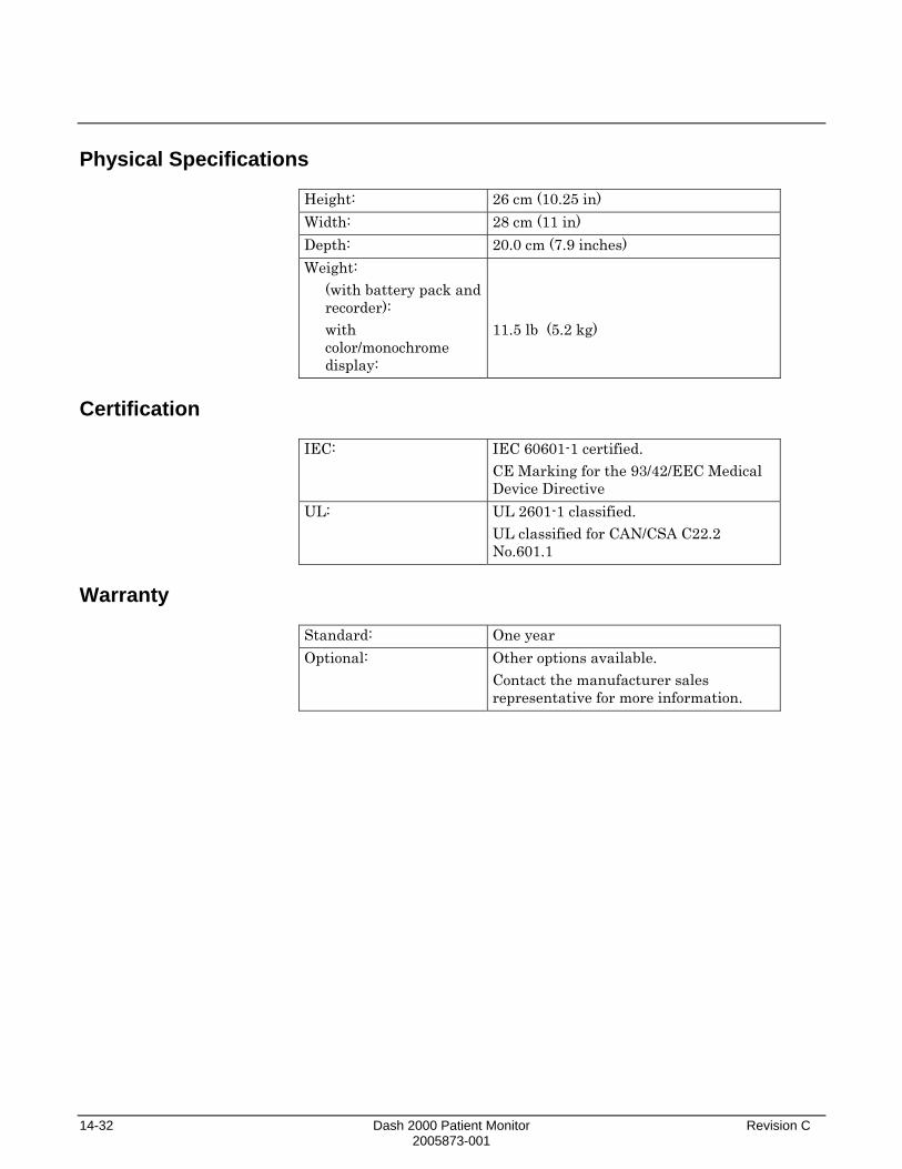
14-32 Dash 2000 Patient Monitor Revision C 2005873-001
Physical Specifications Height: 26 cm (10.25 in) Width: 28 cm (11 in) Depth: 20.0 cm (7.9 inches) Weight:
(with battery pack and recorder): with color/monochrome display:
11.5 lb (5.2 kg)
Certification
IEC: IEC 60601-1 certified.
CE Marking for the 93/42/EEC Medical Device Directive
UL: UL 2601-1 classified. UL classified for CAN/CSA C22.2 No.601.1
Warranty
Standard: One year Optional: Other options available.
Contact the manufacturer sales representative for more information.