Dartmouth-Hitchcock Medical Center Campus Map & Visitors Guide
DARTMOUTH-HITCHCOCK
MEDICAL CENTER
One Medical Center Drive, Lebanon, NH 03756-0001
www.dhmc.org
DEPARTMENT OF RADIOLOGY
DIAGNOSTIC SECTION
DIGITAL IMAGE
STANDARDS
FOR
ROUTINE RADIOGRAPHY
Gerald J. Bergen, RT (R)
© 2005 Dartmouth-Hitchcock Medical Center The contents of DHMC's Digital Image Standards for Routine Radiography may not be reproduced without permission, but we are usually able - and happy - to extend such permission.
First revision April 2005
Second revision May 2006 Third revision September 2008
Fourth Revision April 2016

Acknowledgment
The digital radiographic images displayed in this manual are the product of the skill, ingenuity, and perseverance of the
radiographers of the Dartmouth-Hitchcock Medical Center diagnostic radiology
department. This manual would not have been possible without their professionalism and their dedication to adhering to the
highest standards of image quality. GJB
Preface
Digital Image Standards for Routine Radiography was developed for radiographers and clinicians for the purpose of standardizing the production, storage and display of digital
images. Radiographers are provided a reference for image qualities and orientation and for the
sequencing of digital images before archiving to PACS. Clinicians have a reference for selecting the appropriate positions/projections and
exams to meet their imaging needs and expectations. Clinicians must be aware that the resulting diagnostic value of an exam is affected
by the patient's ability to comply with the demands of the exam requested.
Digital Image Standards for Routine Radiography describes both routine and non-
routine positions/projections performed at Dartmouth-Hitchcock Medical Center. The
routine as indicated by an asterisk is required by radiology, and positions/projections can be omitted from, substituted for or added to the
routine at the discretion of the radiology staff. The patient's ability to safely comply with
imaging requirements and/or the concerns for minimizing radiation exposure will be determining factors for altering the routine.
Additional images may be acquired if the benefit of the diagnostic information outweighs the risk.
This manual does not describe how to perform
the positions/projections listed. The reader is referred to the many excellent radiographic positioning textbooks available. A partial listing
is included at the end of this manual.
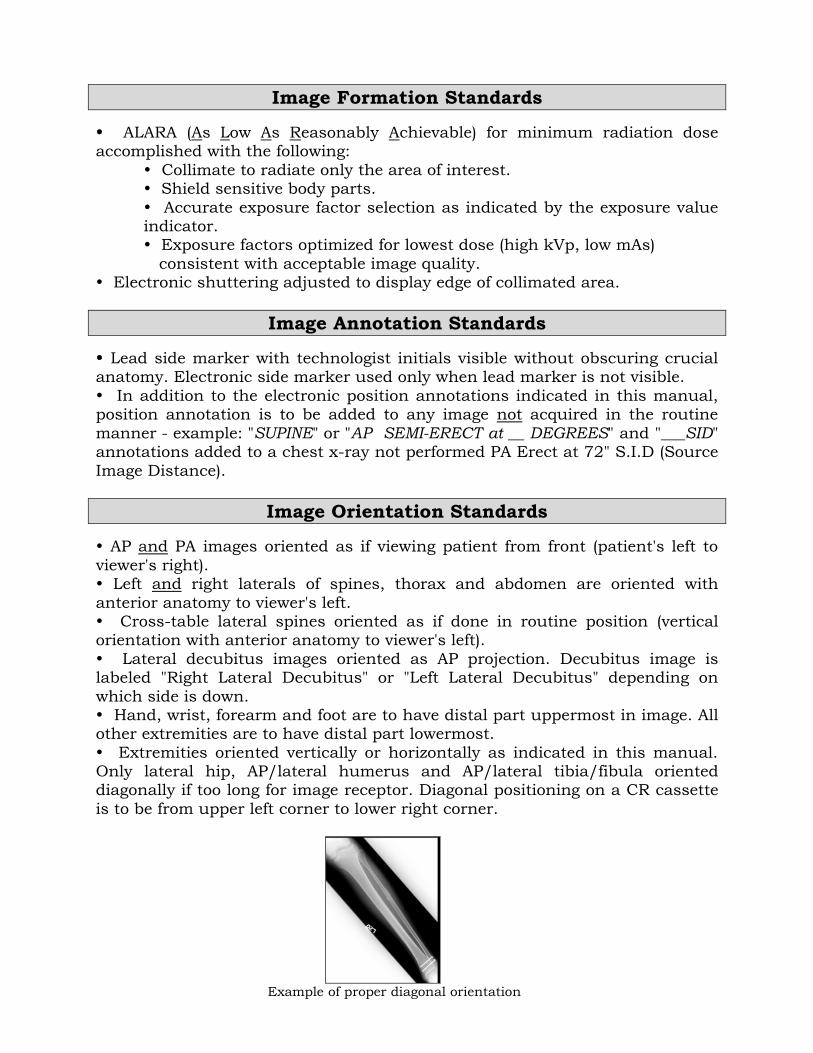
Image Formation Standards
ALARA (As Low As Reasonably Achievable) for minimum radiation dose accomplished with the following:
Collimate to radiate only the area of interest. Shield sensitive body parts.
Accurate exposure factor selection as indicated by the exposure value indicator.
Exposure factors optimized for lowest dose (high kVp, low mAs)
consistent with acceptable image quality. Electronic shuttering adjusted to display edge of collimated area.
Image Annotation Standards
Lead side marker with technologist initials visible without obscuring crucial anatomy. Electronic side marker used only when lead marker is not visible.
In addition to the electronic position annotations indicated in this manual, position annotation is to be added to any image not acquired in the routine
manner - example: "SUPINE" or "AP SEMI-ERECT at __ DEGREES" and "___SID" annotations added to a chest x-ray not performed PA Erect at 72" S.I.D (Source
Image Distance).
Image Orientation Standards
AP and PA images oriented as if viewing patient from front (patient's left to
viewer's right). Left and right laterals of spines, thorax and abdomen are oriented with
anterior anatomy to viewer's left. Cross-table lateral spines oriented as if done in routine position (vertical orientation with anterior anatomy to viewer's left).
Lateral decubitus images oriented as AP projection. Decubitus image is labeled "Right Lateral Decubitus" or "Left Lateral Decubitus" depending on
which side is down. Hand, wrist, forearm and foot are to have distal part uppermost in image. All other extremities are to have distal part lowermost.
Extremities oriented vertically or horizontally as indicated in this manual. Only lateral hip, AP/lateral humerus and AP/lateral tibia/fibula oriented diagonally if too long for image receptor. Diagonal positioning on a CR cassette
is to be from upper left corner to lower right corner.
Example of proper diagonal orientation
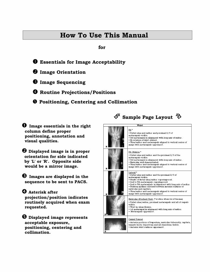
How To Use This Manual
for
Essentials for Image Acceptability
Image Orientation
Image Sequencing
Routine Projections/Positions
Positioning, Centering and Collimation
Sample Page Layout
Image essentials in the right
column define proper
positioning, annotation and visual qualities.
Displayed image is in proper
orientation for side indicated by 'L' or 'R'. Opposite side
would be a mirror image.
Images are displayed in the
sequence to be sent to PACS.
Asterisk after
projection/position indicates routinely acquired when exam requested.
Displayed image represents
acceptable exposure,
positioning, centering and collimation.
Digital Image Standards for Routine Radiography
Imaging Terminology
The following definitions apply to the terminology used in this manual:
Position: The position of the patient's body at the time of imaging. Prone, supine, erect, standing, decubitus, oblique and lateral describe a patient's
position.
Projection: The path of the x-ray beam through the body sometimes
expressed as a double term with the first term indicating entrance side and the second indicating exit side. AP (antero-posterior). PA (postero-anterior),
supero-inferior, infero-superior, lateral (for the head and trunk of the body), medio-lateral or latero-medial (for extremities) describe projections. Axial and semi-axial describe a projection along or nearly along the long axis (sagittal
or coronal plane) of the body.
View: The orientation of an image as viewed by the detector or the viewer.
The terms anterior, posterior, superior, inferior, oblique and lateral used as a view describe the patient's side closest to the detector. The use of the term view has been avoided in this manual to eliminate confusion with positions
and projections.
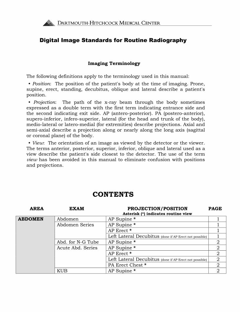
CONTENTS
AREA EXAM PROJECTION/POSITION PAGE Asterisk (*) indicates routine view
ABDOMEN Abdomen AP Supine * 1
Abdomen Series
AP Supine * 1
AP Erect * 1
Left Lateral Decubitus (done if AP Erect not possible) 1
Abd. for N-G Tube AP Supine * 2
Acute Abd. Series AP Supine * 2
AP Erect * 2
Left Lateral Decubitus (done if AP Erect not possible) 2
PA Erect Chest * 2
KUB AP Supine * 2
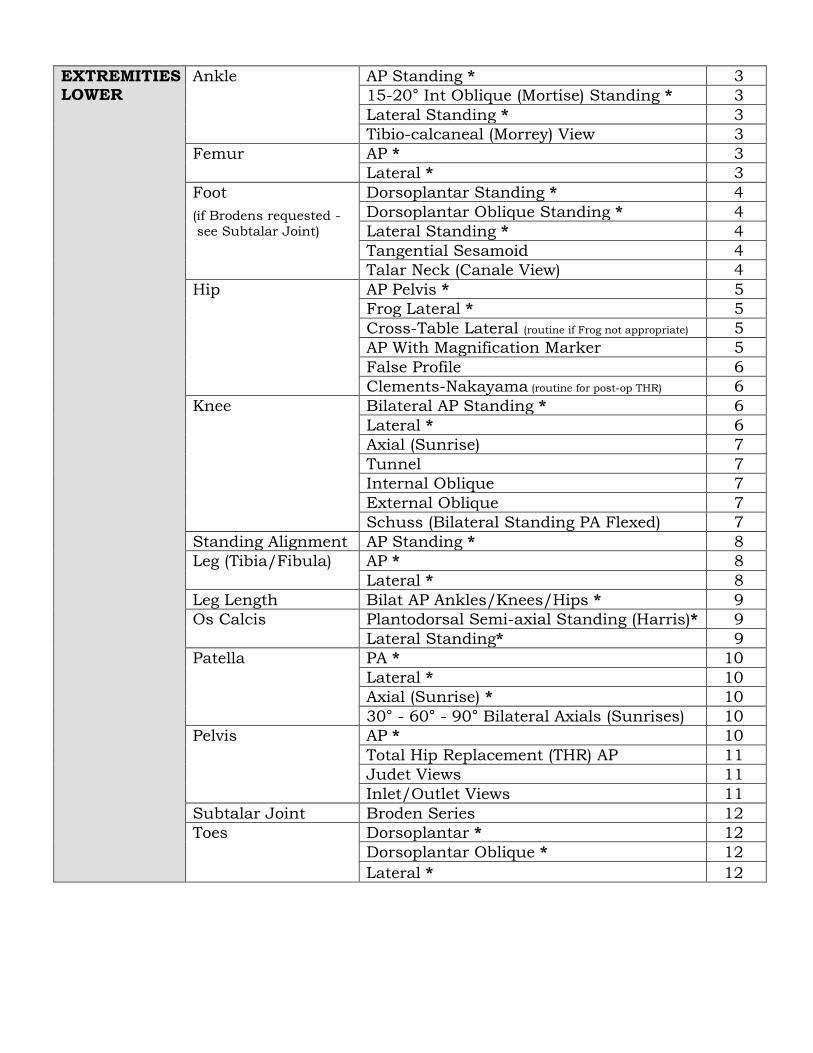
EXTREMITIES - LOWER
Ankle AP Standing * 3
15-20° Int Oblique (Mortise) Standing * 3
Lateral Standing * 3
Tibio-calcaneal (Morrey) View 3
Femur AP * 3
Lateral * 3
Foot
(if Brodens requested -
see Subtalar Joint)
Dorsoplantar Standing * 4
Dorsoplantar Oblique Standing * 4
Lateral Standing * 4
Tangential Sesamoid 4
Talar Neck (Canale View) 4
Hip AP Pelvis * 5
Frog Lateral * 5
Cross-Table Lateral (routine if Frog not appropriate) 5
AP With Magnification Marker 5
False Profile 6
Clements-Nakayama (routine for post-op THR) 6
Knee Bilateral AP Standing * 6
Lateral * 6
Axial (Sunrise) 7
Tunnel 7
Internal Oblique 7
External Oblique 7
Schuss (Bilateral Standing PA Flexed) 7
Standing Alignment AP Standing * 8
Leg (Tibia/Fibula) AP * 8
Lateral * 8
Leg Length Bilat AP Ankles/Knees/Hips * 9
Os Calcis Plantodorsal Semi-axial Standing (Harris)* 9
Lateral Standing* 9
Patella PA * 10
Lateral * 10
Axial (Sunrise) * 10
30° - 60° - 90° Bilateral Axials (Sunrises) 10
Pelvis AP * 10
Total Hip Replacement (THR) AP 11
Judet Views 11
Inlet/Outlet Views 11
Subtalar Joint Broden Series 12
Toes Dorsoplantar * 12
Dorsoplantar Oblique * 12
Lateral * 12
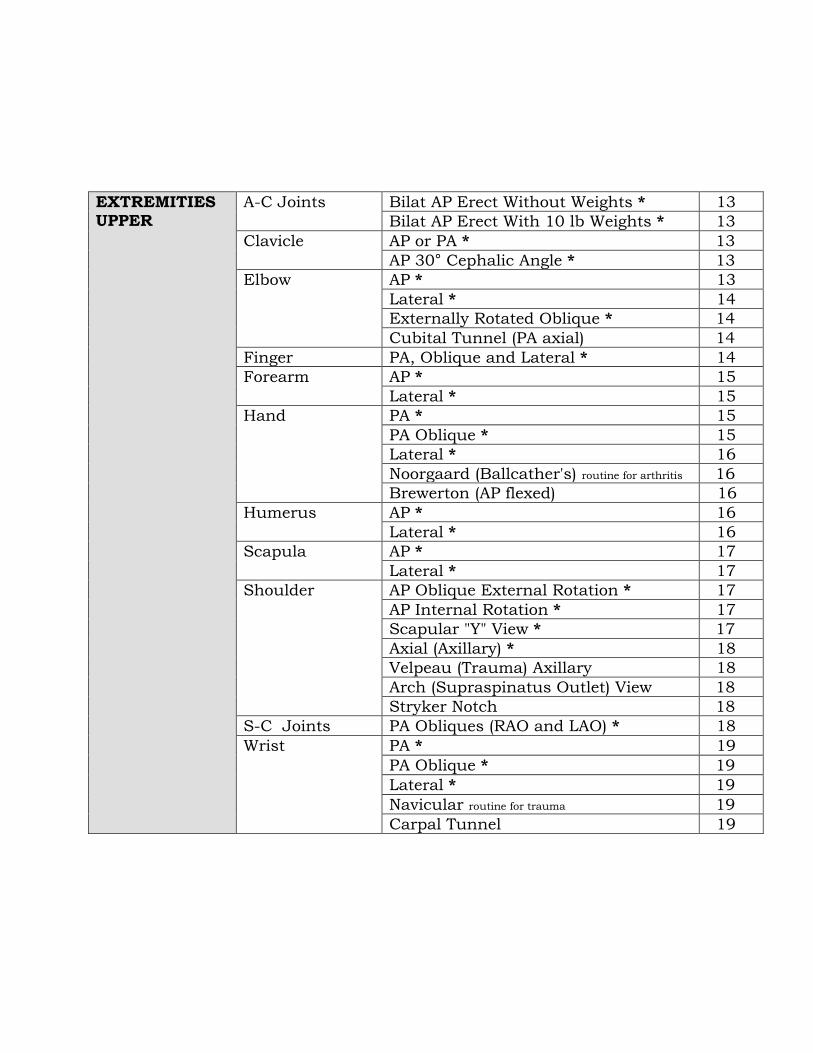
EXTREMITIES UPPER
A-C Joints Bilat AP Erect Without Weights * 13
Bilat AP Erect With 10 lb Weights * 13
Clavicle AP or PA * 13
AP 30° Cephalic Angle * 13
Elbow AP * 13
Lateral * 14
Externally Rotated Oblique * 14
Cubital Tunnel (PA axial) 14
Finger PA, Oblique and Lateral * 14
Forearm AP * 15
Lateral * 15
Hand PA * 15
PA Oblique * 15
Lateral * 16
Noorgaard (Ballcather's) routine for arthritis 16
Brewerton (AP flexed) 16
Humerus AP * 16
Lateral * 16
Scapula AP * 17
Lateral * 17
Shoulder AP Oblique External Rotation * 17
AP Internal Rotation * 17
Scapular "Y" View * 17
Axial (Axillary) * 18
Velpeau (Trauma) Axillary 18
Arch (Supraspinatus Outlet) View 18
Stryker Notch 18
S-C Joints PA Obliques (RAO and LAO) * 18
Wrist PA * 19
PA Oblique * 19
Lateral * 19
Navicular routine for trauma 19
Carpal Tunnel 19
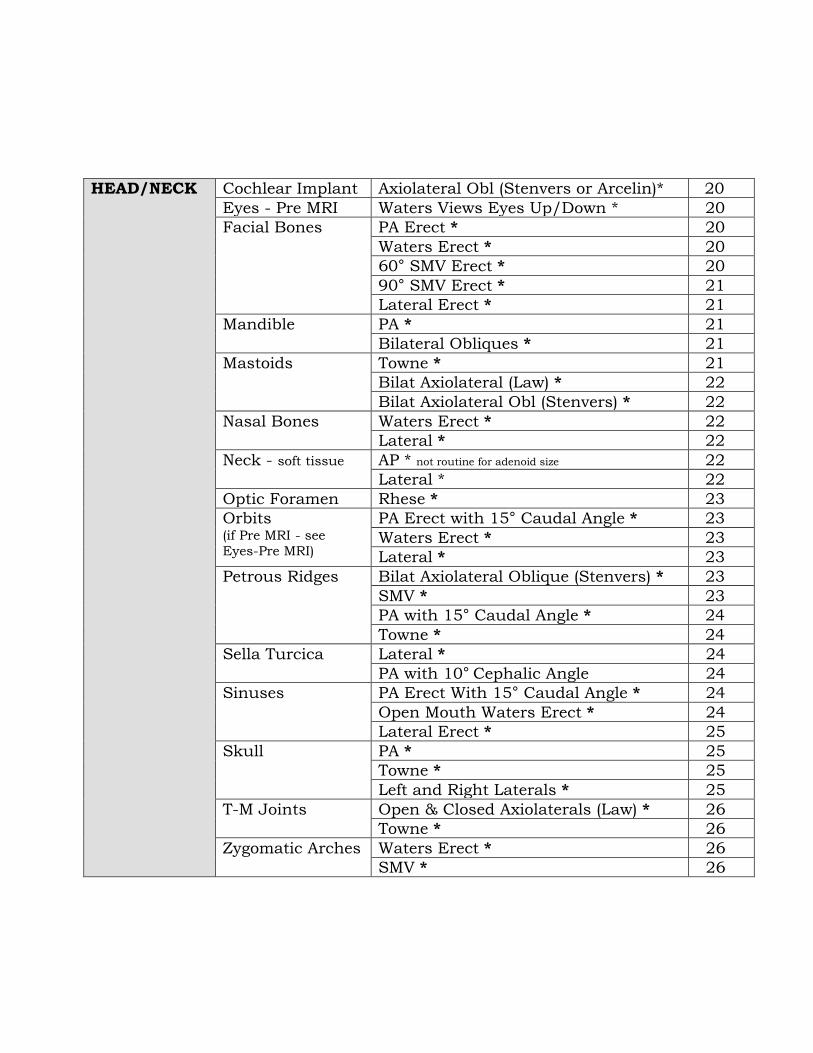
HEAD/NECK Cochlear Implant Axiolateral Obl (Stenvers or Arcelin)* 20
Eyes - Pre MRI Waters Views Eyes Up/Down * 20
Facial Bones PA Erect * 20
Waters Erect * 20
60° SMV Erect * 20
90° SMV Erect * 21
Lateral Erect * 21
Mandible PA * 21
Bilateral Obliques * 21
Mastoids Towne * 21
Bilat Axiolateral (Law) * 22
Bilat Axiolateral Obl (Stenvers) * 22
Nasal Bones Waters Erect * 22
Lateral * 22
Neck - soft tissue AP * not routine for adenoid size 22
Lateral * 22
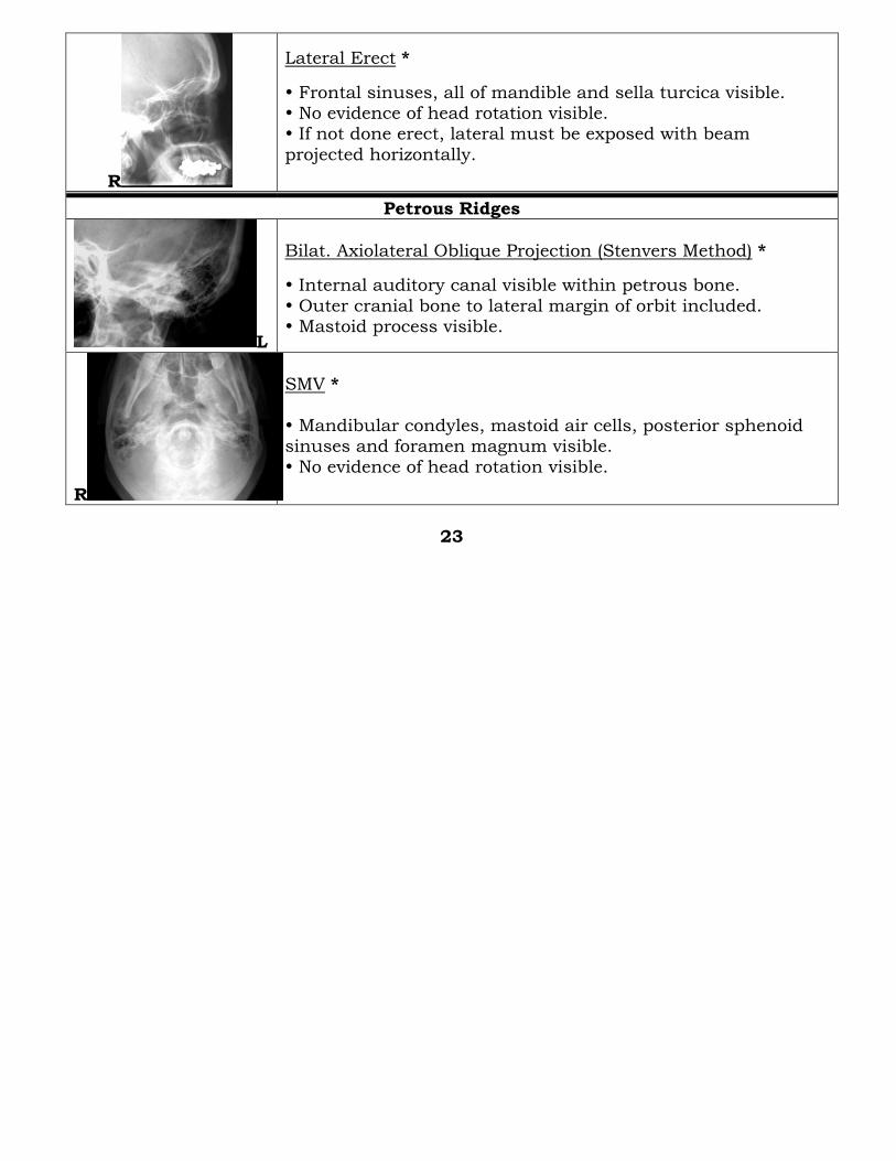
Optic Foramen Rhese * 23
Orbits (if Pre MRI - see
Eyes-Pre MRI)
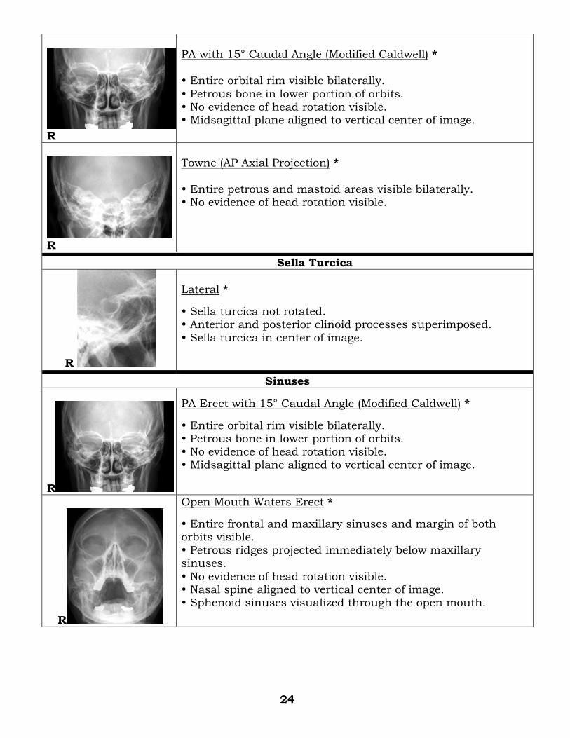
PA Erect with 15° Caudal Angle * 23
Waters Erect * 23
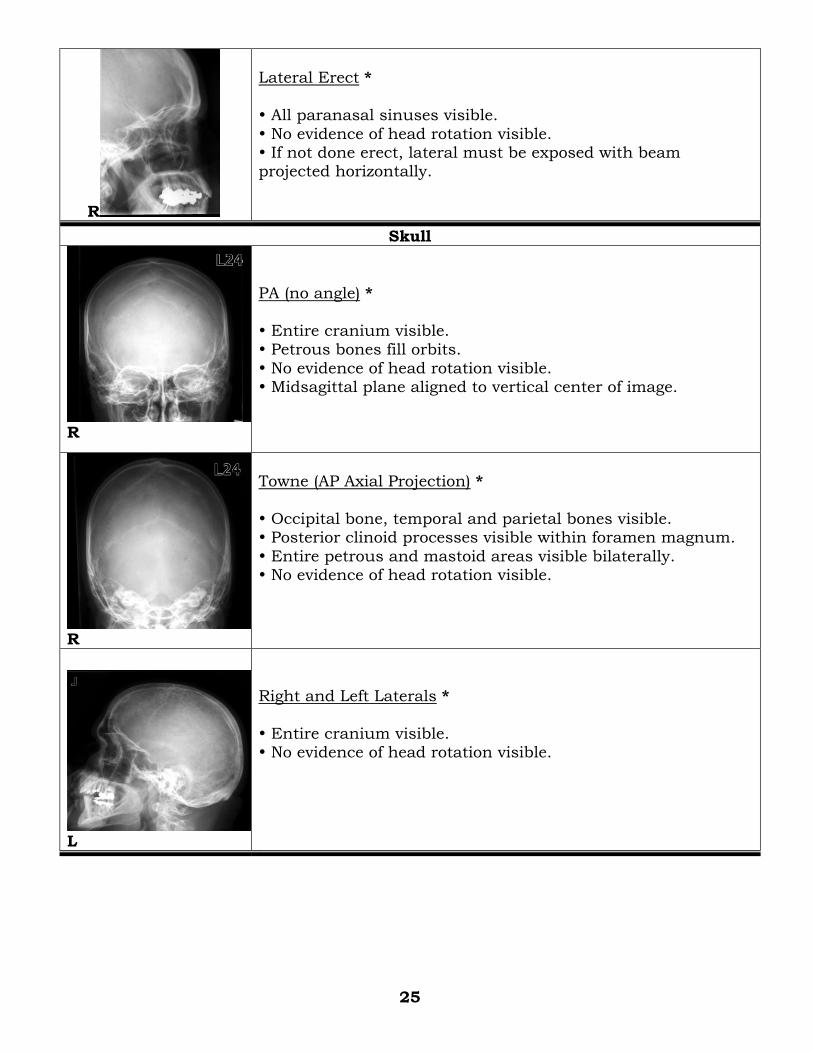
Lateral * 23
Petrous Ridges Bilat Axiolateral Oblique (Stenvers) * 23
SMV * 23
PA with 15° Caudal Angle * 24
Towne * 24
Sella Turcica Lateral * 24
PA with 10° Cephalic Angle 24
Sinuses PA Erect With 15° Caudal Angle * 24
Open Mouth Waters Erect * 24
Lateral Erect * 25
Skull PA * 25
Towne * 25
Left and Right Laterals * 25
T-M Joints Open & Closed Axiolaterals (Law) * 26
Towne * 26
Zygomatic Arches Waters Erect * 26
SMV * 26
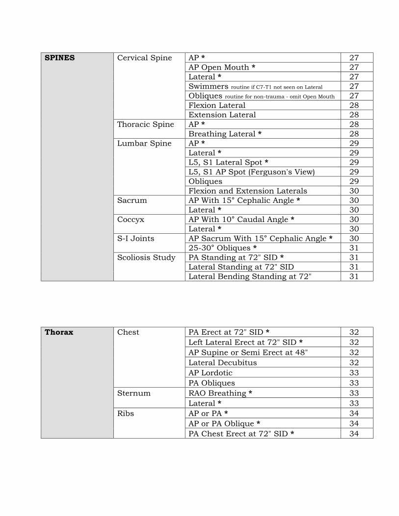
SPINES Cervical Spine AP * 27
AP Open Mouth * 27
Lateral * 27
Swimmers routine if C7-T1 not seen on Lateral 27
Obliques routine for non-trauma - omit Open Mouth 27
Flexion Lateral 28
Extension Lateral 28
Thoracic Spine AP * 28
Breathing Lateral * 28
Lumbar Spine AP * 29
Lateral * 29
L5, S1 Lateral Spot * 29
L5, S1 AP Spot (Ferguson's View) 29
Obliques 29
Flexion and Extension Laterals 30
Sacrum AP With 15° Cephalic Angle * 30
Lateral * 30
Coccyx AP With 10° Caudal Angle * 30
Lateral * 30
S-I Joints AP Sacrum With 15° Cephalic Angle * 30
25-30° Obliques * 31
Scoliosis Study PA Standing at 72" SID * 31
Lateral Standing at 72" SID 31
Lateral Bending Standing at 72" 31
Thorax Chest PA Erect at 72" SID * 32
Left Lateral Erect at 72" SID * 32
AP Supine or Semi Erect at 48" 32
Lateral Decubitus 32
AP Lordotic 33
PA Obliques 33
Sternum RAO Breathing * 33
Lateral * 33
Ribs AP or PA * 34
AP or PA Oblique * 34
PA Chest Erect at 72" SID * 34
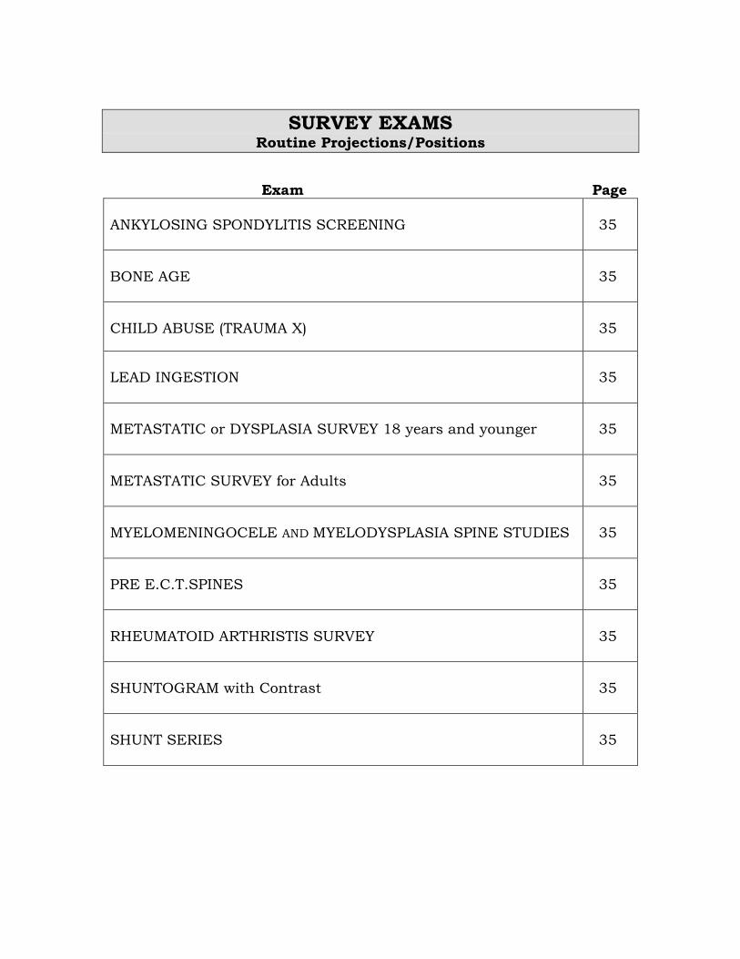
SURVEY EXAMS Routine Projections/Positions
Exam Page
ANKYLOSING SPONDYLITIS SCREENING
35
BONE AGE
35
CHILD ABUSE (TRAUMA X)
35
LEAD INGESTION
35
METASTATIC or DYSPLASIA SURVEY 18 years and younger
35
METASTATIC SURVEY for Adults
35
MYELOMENINGOCELE AND MYELODYSPLASIA SPINE STUDIES
35
PRE E.C.T.SPINES
35
RHEUMATOID ARTHRISTIS SURVEY
35
SHUNTOGRAM with Contrast
35
SHUNT SERIES
35

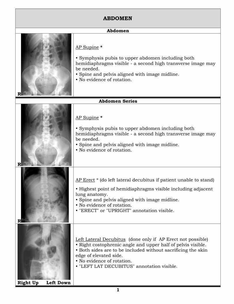
ABDOMEN
Abdomen
R
AP Supine * Symphysis pubis to upper abdomen including both
hemidiaphragms visible - a second high transverse image may be needed.
Spine and pelvis aligned with image midline. No evidence of rotation.
Abdomen Series
R
AP Supine *
Symphysis pubis to upper abdomen including both hemidiaphragms visible - a second high transverse image may be needed.
Spine and pelvis aligned with image midline. No evidence of rotation.
R
AP Erect * (do left lateral decubitus if patient unable to stand)
Highest point of hemidiaphragms visible including adjacent
lung anatomy. Spine and pelvis aligned with image midline. No evidence of rotation.
"ERECT" or "UPRIGHT" annotation visible.
Right Up Left Down
Left Lateral Decubitus (done only if AP Erect not possible)
Right costophrenic angle and upper half of pelvis visible. Both sides are to be included without sacrificing the skin edge of elevated side.
No evidence of rotation. "LEFT LAT DECUBITUS" annotation visible.
1
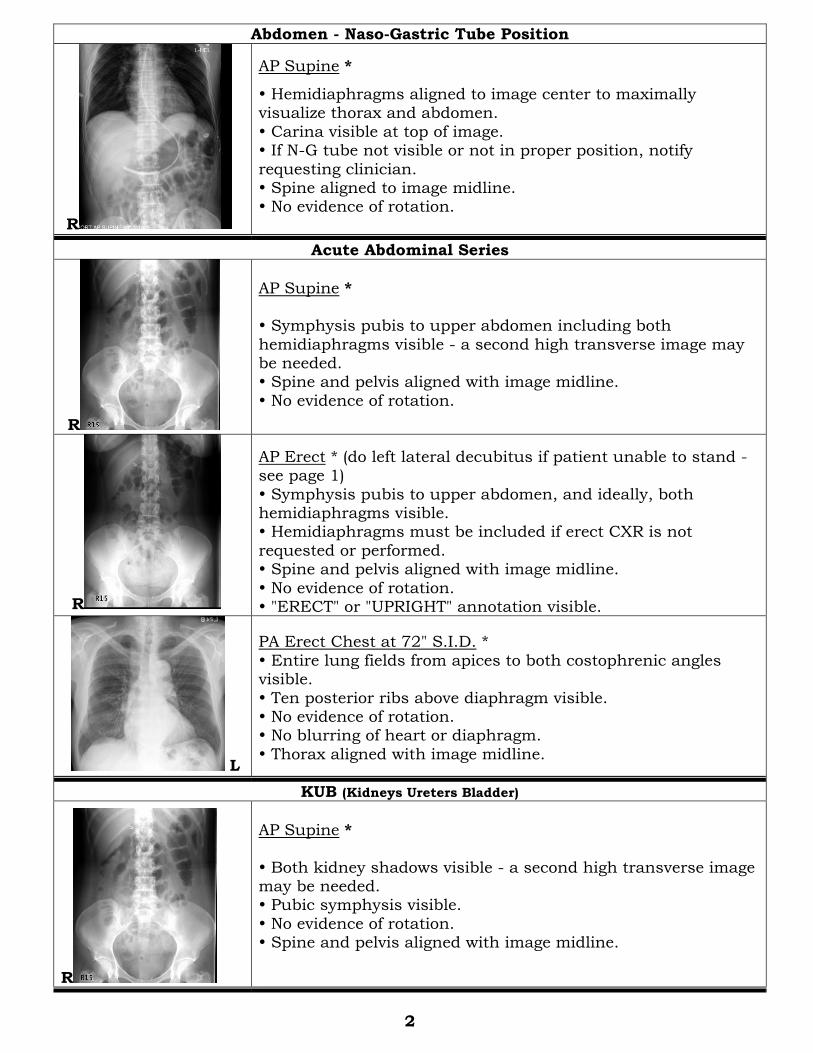
Abdomen - Naso-Gastric Tube Position
R
AP Supine *
Hemidiaphragms aligned to image center to maximally visualize thorax and abdomen.
Carina visible at top of image. If N-G tube not visible or not in proper position, notify
requesting clinician. Spine aligned to image midline. No evidence of rotation.
Acute Abdominal Series
R
AP Supine * Symphysis pubis to upper abdomen including both
hemidiaphragms visible - a second high transverse image may be needed. Spine and pelvis aligned with image midline.
No evidence of rotation.
R
AP Erect * (do left lateral decubitus if patient unable to stand - see page 1)
Symphysis pubis to upper abdomen, and ideally, both hemidiaphragms visible. Hemidiaphragms must be included if erect CXR is not
requested or performed. Spine and pelvis aligned with image midline.
No evidence of rotation. "ERECT" or "UPRIGHT" annotation visible.
L
PA Erect Chest at 72" S.I.D. *
Entire lung fields from apices to both costophrenic angles visible.
Ten posterior ribs above diaphragm visible. No evidence of rotation. No blurring of heart or diaphragm.
Thorax aligned with image midline.
KUB (Kidneys Ureters Bladder)
R
AP Supine *
Both kidney shadows visible - a second high transverse image may be needed. Pubic symphysis visible.
No evidence of rotation. Spine and pelvis aligned with image midline.
2
EXTREMITIES - LOWER
Ankle
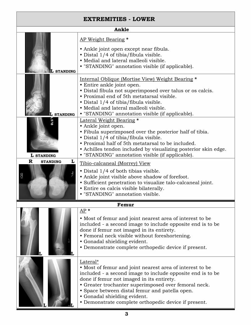
L STANDING
AP Weight Bearing *
Ankle joint open except near fibula.
Distal 1/4 of tibia/fibula visible. Medial and lateral malleoli visible. "STANDING" annotation visible (if applicable).
L STANDING
Internal Oblique (Mortise View) Weight Bearing *
Entire ankle joint open. Distal fibula not superimposed over talus or os calcis. Proximal end of 5th metatarsal visible.
Distal 1/4 of tibia/fibula visible. Medial and lateral malleoli visible. "STANDING" annotation visible (if applicable).
L STANDING
Lateral Weight Bearing * Ankle joint open.
Fibula superimposed over the posterior half of tibia. Distal 1/4 of tibia/fibula visible.
Proximal half of 5th metatarsal to be included. Achilles tendon included by visualizing posterior skin edge. "STANDING" annotation visible (if applicable).
R STANDING L
Tibio-calcaneal (Morrey) View
Distal 1/4 of both tibias visible. Ankle joint visible above shadow of forefoot.
Sufficient penetration to visualize talo-calcaneal joint. Entire os calcis visible bilaterally. "STANDING" annotation visible.
Femur
L L
AP *
Most of femur and joint nearest area of interest to be included - a second image to include opposite end is to be
done if femur not imaged in its entirety. Femoral neck visible without foreshortening. Gonadal shielding evident.
Demonstrate complete orthopedic device if present.
L L
Lateral* Most of femur and joint nearest area of interest to be included - a second image to include opposite end is to be
done if femur not imaged in its entirety. Greater trochanter superimposed over femoral neck.
Space between distal femur and patella open. Gonadal shielding evident. Demonstrate complete orthopedic device if present.
3
Foot
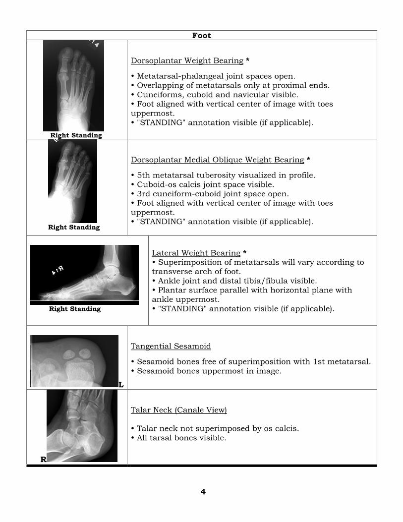
Right Standing
Dorsoplantar Weight Bearing *
Metatarsal-phalangeal joint spaces open. Overlapping of metatarsals only at proximal ends.
Cuneiforms, cuboid and navicular visible. Foot aligned with vertical center of image with toes uppermost.
"STANDING" annotation visible (if applicable).
Right Standing
Dorsoplantar Medial Oblique Weight Bearing *
5th metatarsal tuberosity visualized in profile.
Cuboid-os calcis joint space visible. 3rd cuneiform-cuboid joint space open. Foot aligned with vertical center of image with toes
uppermost. "STANDING" annotation visible (if applicable).
Right Standing
Lateral Weight Bearing * Superimposition of metatarsals will vary according to transverse arch of foot.
Ankle joint and distal tibia/fibula visible. Plantar surface parallel with horizontal plane with ankle uppermost.
"STANDING" annotation visible (if applicable).
L
Tangential Sesamoid
Sesamoid bones free of superimposition with 1st metatarsal.
Sesamoid bones uppermost in image.
R
Talar Neck (Canale View) Talar neck not superimposed by os calcis.
All tarsal bones visible.
4
5
Hip
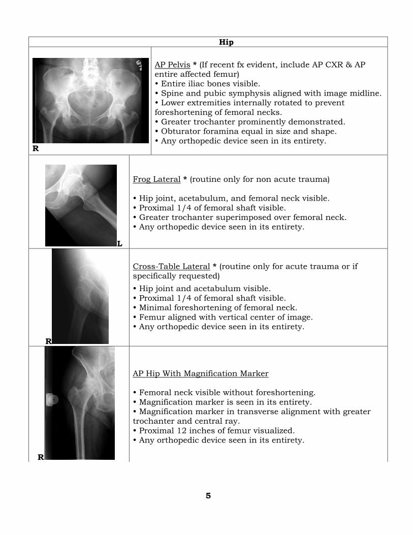
R
AP Pelvis * (If recent fx evident, include AP CXR & AP entire affected femur) Entire iliac bones visible.
Spine and pubic symphysis aligned with image midline. Lower extremities internally rotated to prevent
foreshortening of femoral necks. Greater trochanter prominently demonstrated. Obturator foramina equal in size and shape.
Any orthopedic device seen in its entirety.
L
Frog Lateral * (routine only for non acute trauma)
Hip joint, acetabulum, and femoral neck visible.
Proximal 1/4 of femoral shaft visible. Greater trochanter superimposed over femoral neck. Any orthopedic device seen in its entirety.
R
Cross-Table Lateral * (routine only for acute trauma or if specifically requested)
Hip joint and acetabulum visible.
Proximal 1/4 of femoral shaft visible. Minimal foreshortening of femoral neck.
Femur aligned with vertical center of image. Any orthopedic device seen in its entirety.
R
AP Hip With Magnification Marker Femoral neck visible without foreshortening.
Magnification marker is seen in its entirety. Magnification marker in transverse alignment with greater trochanter and central ray.
Proximal 12 inches of femur visualized. Any orthopedic device seen in its entirety.
R
False Profile
Anterior acetabular surface visible.
Greater trochanter superimposed over femoral neck. Lesser trochanter visible.
Acetabulum and femur free of superimposition from soft tissue of contra lateral thigh. Femur aligned with vertical center of image.
If requested with magnification marker, marker is to be in transverse alignment with greater trochanter and central ray. Also, proximal 12 inches of femur visualized.
R
Clements-Nakayama (routine for post-op total hip replacement)
Acetabulum and proximal femur visible. Acetabulum and femur free of superimposition from soft
tissue of contra lateral thigh. Any orthopedic device seen in its entirety.
Femur aligned with vertical center of image.
Knee
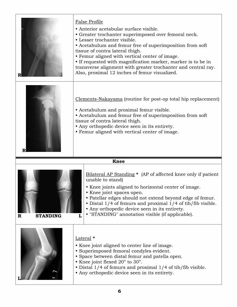
R STANDING L
Bilateral AP Standing * (AP of affected knee only if patient
unable to stand)
Knee joints aligned to horizontal center of image.
Knee joint spaces open. Patellar edges should not extend beyond edge of femur. Distal 1/4 of femurs and proximal 1/4 of tib/fib visible.
Any orthopedic device seen in its entirety. "STANDING" annotation visible (if applicable).
L
Lateral *
Knee joint aligned to center line of image.
Superimposed femoral condyles evident. Space between distal femur and patella open.
Knee joint flexed 20° to 30°. Distal 1/4 of femurs and proximal 1/4 of tib/fib visible. Any orthopedic device seen in its entirety.
6
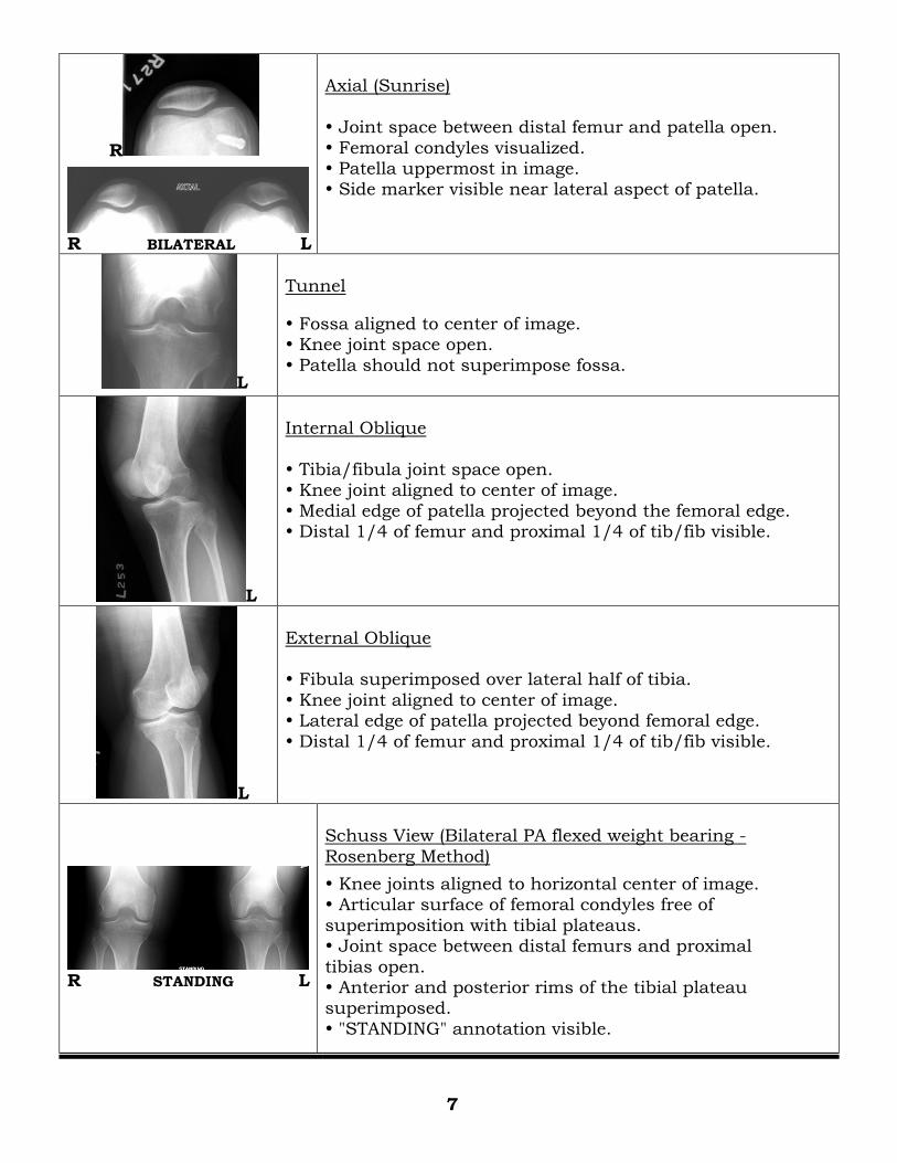
R
R BILATERAL L
Axial (Sunrise)
Joint space between distal femur and patella open.
Femoral condyles visualized. Patella uppermost in image. Side marker visible near lateral aspect of patella.
L
Tunnel
Fossa aligned to center of image. Knee joint space open.
Patella should not superimpose fossa.
L
Internal Oblique
Tibia/fibula joint space open. Knee joint aligned to center of image.
Medial edge of patella projected beyond the femoral edge. Distal 1/4 of femur and proximal 1/4 of tib/fib visible.
L
External Oblique Fibula superimposed over lateral half of tibia.
Knee joint aligned to center of image. Lateral edge of patella projected beyond femoral edge.
Distal 1/4 of femur and proximal 1/4 of tib/fib visible.
R STANDING L
Schuss View (Bilateral PA flexed weight bearing -
Rosenberg Method)
Knee joints aligned to horizontal center of image. Articular surface of femoral condyles free of
superimposition with tibial plateaus. Joint space between distal femurs and proximal
tibias open. Anterior and posterior rims of the tibial plateau superimposed.
"STANDING" annotation visible.
7
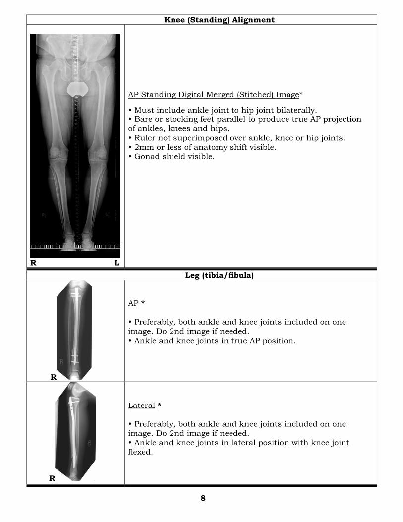
Knee (Standing) Alignment
R L
AP Standing Digital Merged (Stitched) Image*
Must include ankle joint to hip joint bilaterally. Bare or stocking feet parallel to produce true AP projection of ankles, knees and hips.
Ruler not superimposed over ankle, knee or hip joints. 2mm or less of anatomy shift visible. Gonad shield visible.
Leg (tibia/fibula)
R
AP *
Preferably, both ankle and knee joints included on one
image. Do 2nd image if needed. Ankle and knee joints in true AP position.
R
Lateral *
Preferably, both ankle and knee joints included on one image. Do 2nd image if needed.
Ankle and knee joints in lateral position with knee joint flexed.
8
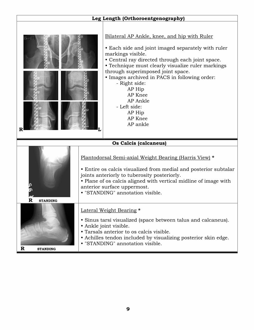
Leg Length (Orthoroentgenography)
R L
Bilateral AP Ankle, knee, and hip with Ruler
Each side and joint imaged separately with ruler
markings visible. Central ray directed through each joint space. Technique must clearly visualize ruler markings
through superimposed joint space. Images archived in PACS in following order: - Right side:
AP Hip AP Knee
AP Ankle - Left side: AP Hip
AP Knee AP ankle
Os Calcis (calcaneus)
R STANDING
Plantodorsal Semi-axial Weight Bearing (Harris View) * Entire os calcis visualized from medial and posterior subtalar
joints anteriorly to tuberosity posteriorly. Plane of os calcis aligned with vertical midline of image with anterior surface uppermost.
"STANDING" annotation visible.
R STANDING
Lateral Weight Bearing *
Sinus tarsi visualized (space between talus and calcaneus).
Ankle joint visible. Tarsals anterior to os calcis visible.
Achilles tendon included by visualizing posterior skin edge. "STANDING" annotation visible.
9
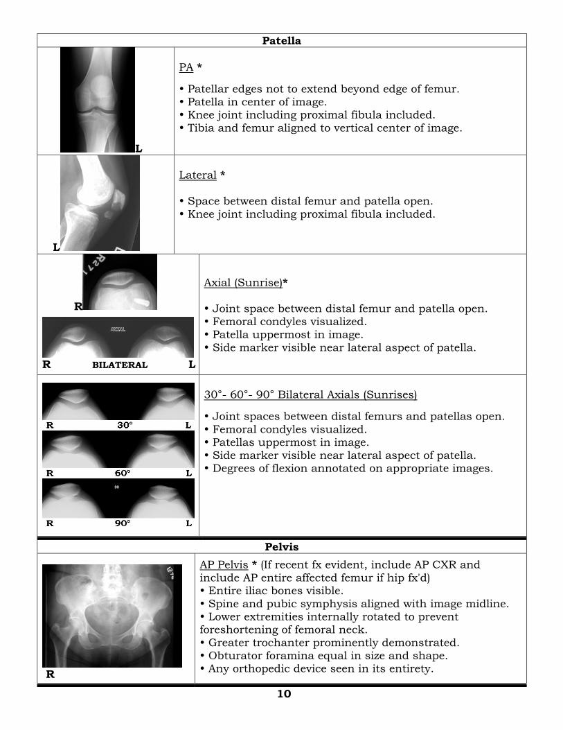
Patella
L
PA *
Patellar edges not to extend beyond edge of femur. Patella in center of image. Knee joint including proximal fibula included.
Tibia and femur aligned to vertical center of image.
L
Lateral *
Space between distal femur and patella open.
Knee joint including proximal fibula included.
R
R BILATERAL L
Axial (Sunrise)*
Joint space between distal femur and patella open. Femoral condyles visualized. Patella uppermost in image.
Side marker visible near lateral aspect of patella.
30°- 60°- 90° Bilateral Axials (Sunrises)
Joint spaces between distal femurs and patellas open.
Femoral condyles visualized. Patellas uppermost in image.
Side marker visible near lateral aspect of patella. Degrees of flexion annotated on appropriate images.
Pelvis
R
AP Pelvis * (If recent fx evident, include AP CXR and
include AP entire affected femur if hip fx'd) Entire iliac bones visible.
Spine and pubic symphysis aligned with image midline. Lower extremities internally rotated to prevent foreshortening of femoral neck.
Greater trochanter prominently demonstrated. Obturator foramina equal in size and shape. Any orthopedic device seen in its entirety.
10
R
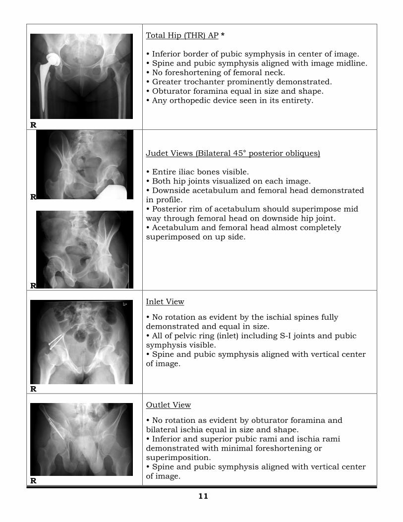
Total Hip (THR) AP *
Inferior border of pubic symphysis in center of image. Spine and pubic symphysis aligned with image midline.
No foreshortening of femoral neck. Greater trochanter prominently demonstrated.
Obturator foramina equal in size and shape. Any orthopedic device seen in its entirety.
R
R
Judet Views (Bilateral 45° posterior obliques)
Entire iliac bones visible. Both hip joints visualized on each image.
Downside acetabulum and femoral head demonstrated in profile. Posterior rim of acetabulum should superimpose mid
way through femoral head on downside hip joint. Acetabulum and femoral head almost completely superimposed on up side.
R
Inlet View
No rotation as evident by the ischial spines fully demonstrated and equal in size.
All of pelvic ring (inlet) including S-I joints and pubic symphysis visible. Spine and pubic symphysis aligned with vertical center
of image.
R
Outlet View
No rotation as evident by obturator foramina and
bilateral ischia equal in size and shape. Inferior and superior pubic rami and ischia rami
demonstrated with minimal foreshortening or superimposition. Spine and pubic symphysis aligned with vertical center
of image.
11
Subtalar Joint
R 10 DEGREES R 20 DEGREES
R 30 DEGREES R 40 DEGREES
Broden Series with 10°, 20°, 30° and 40° Cephalic Angles Distal tibia/fibula and entire talus and os calcis
visible in all views. Posterior subtalar joint space visible in all views. Tibia/fibula aligned to vertical center of image.
Each image annotated with appropriate degrees of angle.
Toes
L
Dorsoplantar * Joint spaces open.
Majority of adjacent metatarsal visible. Distal phalanx uppermost in image.
L
Dorsoplantar (or Plantodorso) Oblique *
Joint spaces open. Majority of adjacent metatarsal visible. Distal phalanx uppermost in image.
L
Lateral *
Toes separated to prevent superimposition. Metatarsal-phalangeal joint visible.
Joint spaces open. Distal phalanx uppermost in image.
12
UPPER EXTREMITIES
Acromio-Clavicular Joints
R L
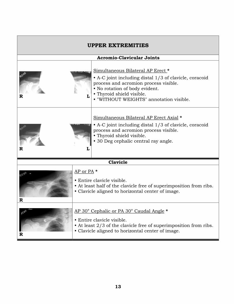
Simultaneous Bilateral AP Erect *
A-C joint including distal 1/3 of clavicle, coracoid
process and acromion process visible. No rotation of body evident. Thyroid shield visible.
"WITHOUT WEIGHTS" annotation visible.
R L
Simultaneous Bilateral AP Erect Axial *
A-C joint including distal 1/3 of clavicle, coracoid process and acromion process visible. Thyroid shield visible.
30 Deg cephalic central ray angle.
Clavicle
R
AP or PA *
Entire clavicle visible. At least half of the clavicle free of superimposition from ribs.
Clavicle aligned to horizontal center of image.
R
AP 30° Cephalic or PA 30° Caudal Angle *
Entire clavicle visible.
At least 2/3 of the clavicle free of superimposition from ribs. Clavicle aligned to horizontal center of image.
13
Elbow
R
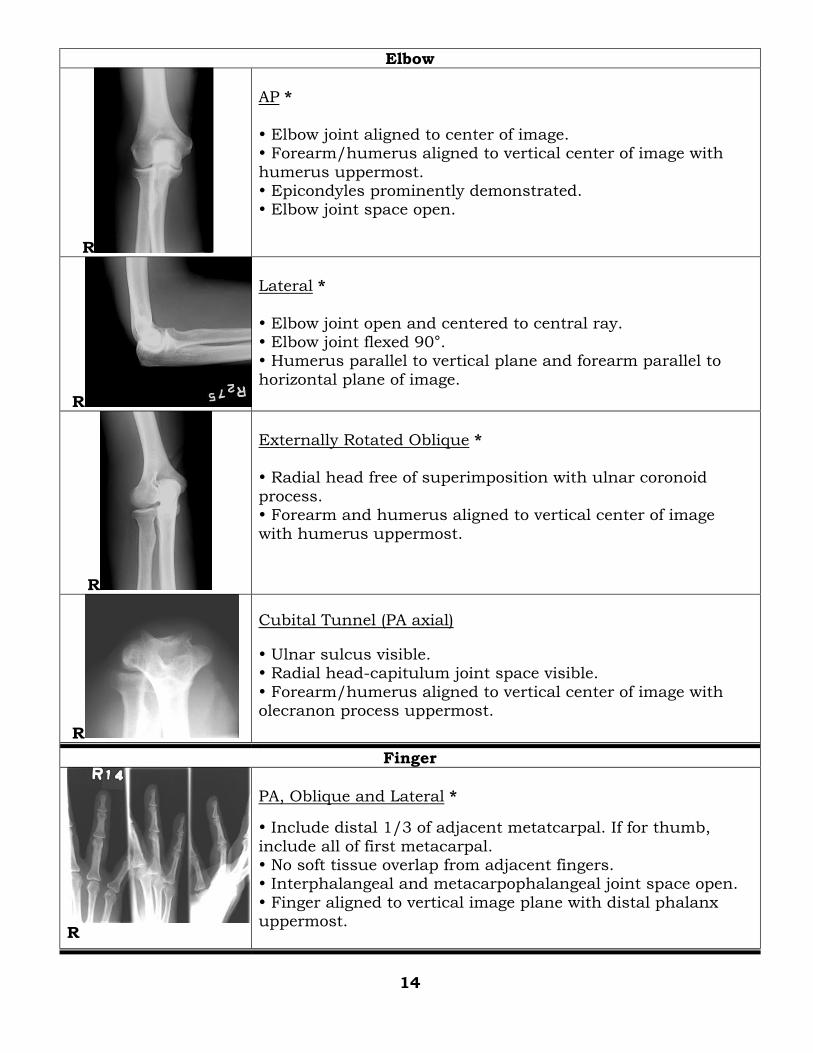
AP *
Elbow joint aligned to center of image. Forearm/humerus aligned to vertical center of image with
humerus uppermost. Epicondyles prominently demonstrated. Elbow joint space open.
R
Lateral *
Elbow joint open and centered to central ray. Elbow joint flexed 90°. Humerus parallel to vertical plane and forearm parallel to
horizontal plane of image.
R
Externally Rotated Oblique * Radial head free of superimposition with ulnar coronoid
process. Forearm and humerus aligned to vertical center of image
with humerus uppermost.
R
Cubital Tunnel (PA axial)
Ulnar sulcus visible. Radial head-capitulum joint space visible.
Forearm/humerus aligned to vertical center of image with olecranon process uppermost.
Finger
R
PA, Oblique and Lateral *
Include distal 1/3 of adjacent metatcarpal. If for thumb,
include all of first metacarpal. No soft tissue overlap from adjacent fingers. Interphalangeal and metacarpophalangeal joint space open.
Finger aligned to vertical image plane with distal phalanx uppermost.
14
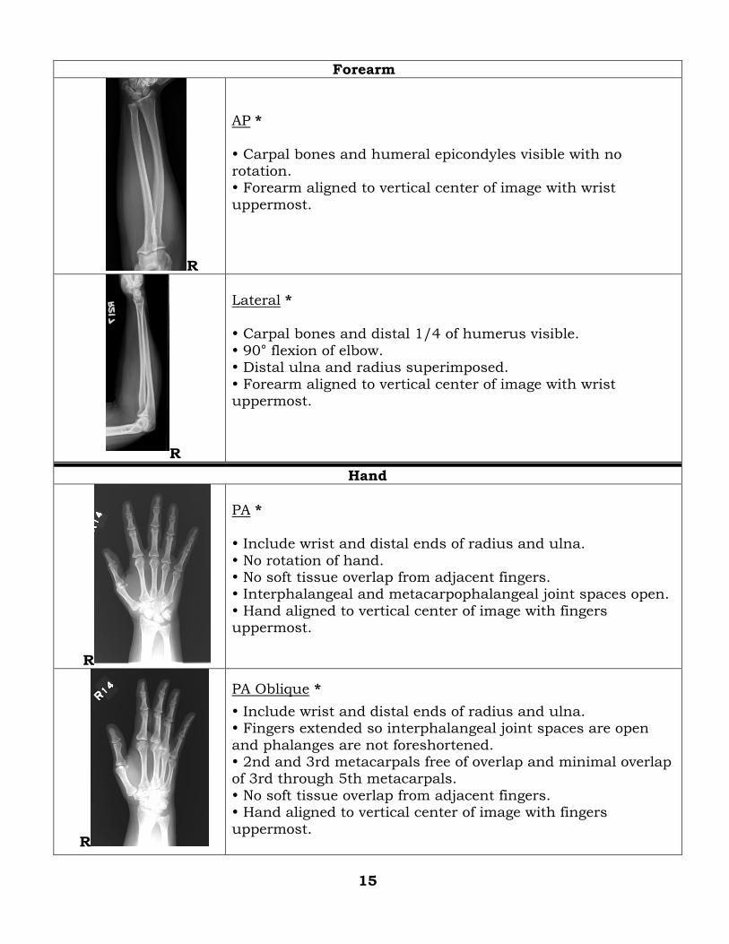
Forearm
R
AP *
Carpal bones and humeral epicondyles visible with no rotation. Forearm aligned to vertical center of image with wrist
uppermost.
R
Lateral * Carpal bones and distal 1/4 of humerus visible.
90° flexion of elbow. Distal ulna and radius superimposed.
Forearm aligned to vertical center of image with wrist uppermost.
Hand
R
PA *
Include wrist and distal ends of radius and ulna.
No rotation of hand. No soft tissue overlap from adjacent fingers. Interphalangeal and metacarpophalangeal joint spaces open.
Hand aligned to vertical center of image with fingers uppermost.
R
PA Oblique *
Include wrist and distal ends of radius and ulna. Fingers extended so interphalangeal joint spaces are open
and phalanges are not foreshortened. 2nd and 3rd metacarpals free of overlap and minimal overlap of 3rd through 5th metacarpals.
No soft tissue overlap from adjacent fingers. Hand aligned to vertical center of image with fingers
uppermost.
15
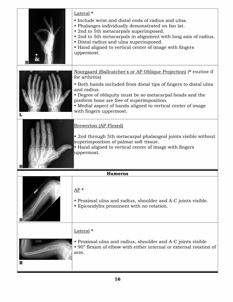
R
Lateral *
Include wrist and distal ends of radius and ulna.
Phalanges individually demonstrated on fan lat. 2nd to 5th metacarpals superimposed. 2nd to 5th metacarpals in alignment with long axis of radius.
Distal radius and ulna superimposed. Hand aligned to vertical center of image with fingers
uppermost.
L
Noorgaard (Ballcatcher's or AP Oblique Projection) (* routine if for arthritis)
Both hands included from distal tips of fingers to distal ulna and radius. Degree of obliquity must be so metacarpal heads and the
pisiform bone are free of superimposition. Medial aspect of hands aligned to vertical center of image
with fingers uppermost.
R
Brewerton (AP Flexed)
2nd through 5th metacarpal phalangeal joints visible without superimposition of palmar soft tissue. Hand aligned to vertical center of image with fingers
uppermost.
Humerus
R
AP *
Proximal ulna and radius, shoulder and A-C joints visible. Epicondyles prominent with no rotation.
R
Lateral * Proximal ulna and radius, shoulder and A-C joints visible
90° flexion of elbow with either internal or external rotation of arm.
16
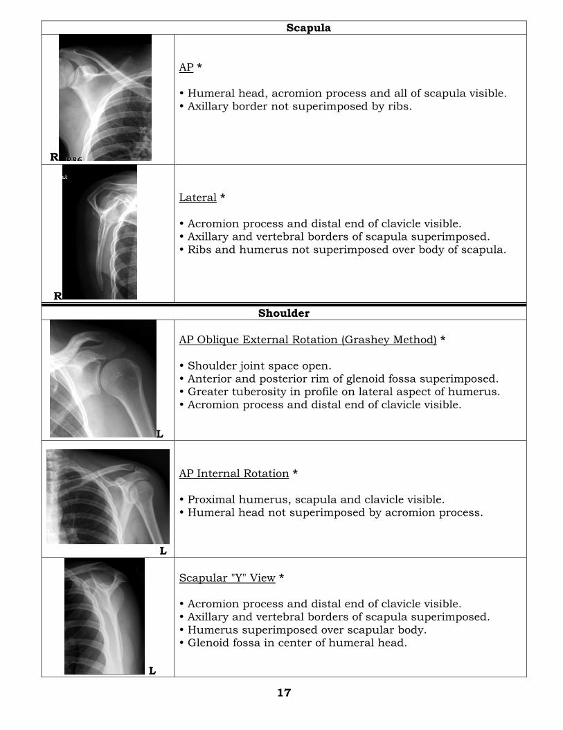
Scapula
R
AP *
Humeral head, acromion process and all of scapula visible. Axillary border not superimposed by ribs.
R
Lateral *
Acromion process and distal end of clavicle visible. Axillary and vertebral borders of scapula superimposed.
Ribs and humerus not superimposed over body of scapula.
Shoulder
L
AP Oblique External Rotation (Grashey Method) *
Shoulder joint space open.
Anterior and posterior rim of glenoid fossa superimposed. Greater tuberosity in profile on lateral aspect of humerus. Acromion process and distal end of clavicle visible.
L
AP Internal Rotation *
Proximal humerus, scapula and clavicle visible. Humeral head not superimposed by acromion process.
L
Scapular "Y" View *
Acromion process and distal end of clavicle visible. Axillary and vertebral borders of scapula superimposed.
Humerus superimposed over scapular body. Glenoid fossa in center of humeral head.
17
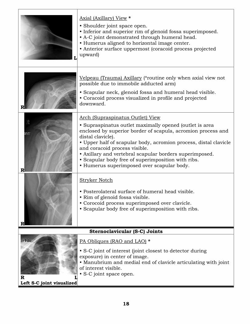
L
Axial (Axillary) View *
Shoulder joint space open. Inferior and superior rim of glenoid fossa superimposed. A-C joint demonstrated through humeral head.
Humerus aligned to horizontal image center. Anterior surface uppermost (coracoid process projected upward)
R
Velpeau (Trauma) Axillary (*routine only when axial view not
possible due to immobile adducted arm)
Scapular neck, glenoid fossa and humeral head visible. Coracoid process visualized in profile and projected downward.
R
Arch (Supraspinatus Outlet) View
Supraspinatus outlet maximally opened (outlet is area enclosed by superior border of scapula, acromion process and
distal clavicle). Upper half of scapular body, acromion process, distal clavicle and coracoid process visible.
Axillary and vertebral scapular borders superimposed. Scapular body free of superimposition with ribs.
Humerus superimposed over scapular body.
R
Stryker Notch
Posterolateral surface of humeral head visible. Rim of glenoid fossa visible.
Corocoid process superimposed over clavicle. Scapular body free of superimposition with ribs.
Sternoclavicular (S-C) Joints
R L Left S-C joint visualized
PA Obliques (RAO and LAO) *
S-C joint of interest (joint closest to detector during
exposure) in center of image. Manubrium and medial end of clavicle articulating with joint
of interest visible. S-C joint space open.
18
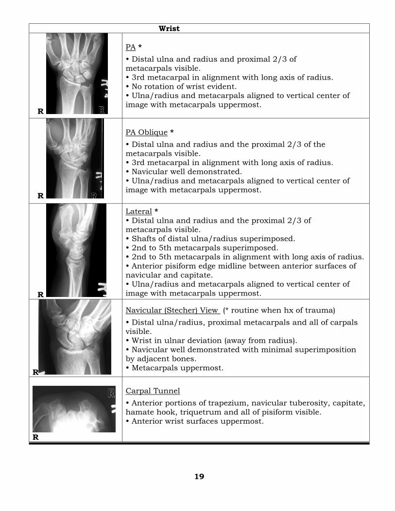
Wrist
R
PA *
Distal ulna and radius and proximal 2/3 of
metacarpals visible. 3rd metacarpal in alignment with long axis of radius.
No rotation of wrist evident. Ulna/radius and metacarpals aligned to vertical center of image with metacarpals uppermost.
R
PA Oblique *
Distal ulna and radius and the proximal 2/3 of the
metacarpals visible. 3rd metacarpal in alignment with long axis of radius. Navicular well demonstrated.
Ulna/radius and metacarpals aligned to vertical center of image with metacarpals uppermost.
R
Lateral *
Distal ulna and radius and the proximal 2/3 of metacarpals visible. Shafts of distal ulna/radius superimposed.
2nd to 5th metacarpals superimposed. 2nd to 5th metacarpals in alignment with long axis of radius.
Anterior pisiform edge midline between anterior surfaces of navicular and capitate. Ulna/radius and metacarpals aligned to vertical center of
image with metacarpals uppermost.
R
Navicular (Stecher) View (* routine when hx of trauma)
Distal ulna/radius, proximal metacarpals and all of carpals visible. Wrist in ulnar deviation (away from radius).
Navicular well demonstrated with minimal superimposition by adjacent bones.
Metacarpals uppermost.
R
Carpal Tunnel
Anterior portions of trapezium, navicular tuberosity, capitate,
hamate hook, triquetrum and all of pisiform visible. Anterior wrist surfaces uppermost.
19
HEAD / NECK
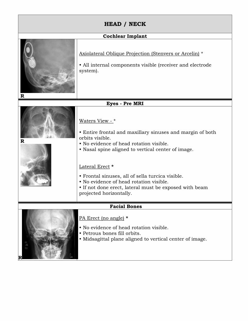
Cochlear Implant
Axiolateral Oblique Projection (Stenvers or Arcelin) *
All internal components visible (receiver and electrode system).
R
Eyes - Pre MRI
R
Waters View - *
Entire frontal and maxillary sinuses and margin of both orbits visible. No evidence of head rotation visible.
Nasal spine aligned to vertical center of image.
Lateral Erect *
Frontal sinuses, all of sella turcica visible. No evidence of head rotation visible. If not done erect, lateral must be exposed with beam
projected horizontally.
Facial Bones
R
PA Erect (no angle) *
No evidence of head rotation visible. Petrous bones fill orbits. Midsagittal plane aligned to vertical center of image.
R
Waters Erect (Parietoacantheal Projection) *
Entire frontal and maxillary sinuses, margin of both orbits and zygomatic arches visible. Petrous ridges projected immediately below maxillary
sinuses. No evidence of head rotation visible.
Nasal spine aligned to vertical center of image.
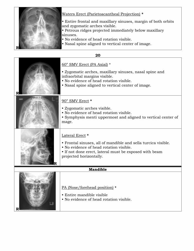
20
R
60° SMV Erect (PA Axial) *
Zygomatic arches, maxillary sinuses, nasal spine and
infraorbital margins visible. No evidence of head rotation visible. Nasal spine aligned to vertical center of image.
90° SMV Erect *
Zygomatic arches visible.
No evidence of head rotation visible. Symphysis menti uppermost and aligned to vertical center of mage.
R
Lateral Erect *
Frontal sinuses, all of mandible and sella turcica visible. No evidence of head rotation visible. If not done erect, lateral must be exposed with beam
projected horizontally.
Mandible
R
PA (Nose/forehead position) *
Entire mandible visible No evidence of head rotation visible.
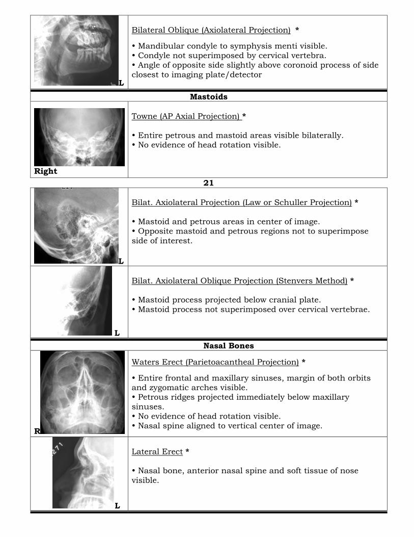
L
Bilateral Oblique (Axiolateral Projection) *
Mandibular condyle to symphysis menti visible. Condyle not superimposed by cervical vertebra. Angle of opposite side slightly above coronoid process of side
closest to imaging plate/detector
Mastoids
Right
Towne (AP Axial Projection) *
Entire petrous and mastoid areas visible bilaterally. No evidence of head rotation visible.
21
L
Bilat. Axiolateral Projection (Law or Schuller Projection) *
Mastoid and petrous areas in center of image. Opposite mastoid and petrous regions not to superimpose
side of interest.
L
Bilat. Axiolateral Oblique Projection (Stenvers Method) * Mastoid process projected below cranial plate.
Mastoid process not superimposed over cervical vertebrae.
Nasal Bones
R
Waters Erect (Parietoacantheal Projection) *
Entire frontal and maxillary sinuses, margin of both orbits and zygomatic arches visible. Petrous ridges projected immediately below maxillary
sinuses. No evidence of head rotation visible. Nasal spine aligned to vertical center of image.
L
Lateral Erect * Nasal bone, anterior nasal spine and soft tissue of nose
visible.
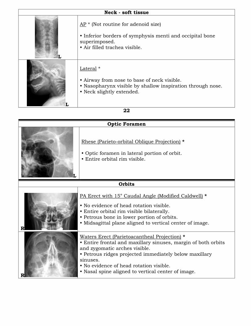
Neck - soft tissue
L
AP * (Not routine for adenoid size) Inferior borders of symphysis menti and occipital bone
superimposed. Air filled trachea visible.
L
Lateral *
Airway from nose to base of neck visible. Nasopharynx visible by shallow inspiration through nose.
Neck slightly extended.
22
Optic Foramen
L
Rhese (Parieto-orbital Oblique Projection) *
Optic foramen in lateral portion of orbit.
Entire orbital rim visible.
Orbits
R
PA Erect with 15° Caudal Angle (Modified Caldwell) *
No evidence of head rotation visible.
Entire orbital rim visible bilaterally. Petrous bone in lower portion of orbits. Midsagittal plane aligned to vertical center of image.
R
Waters Erect (Parietoacantheal Projection) *
Entire frontal and maxillary sinuses, margin of both orbits and zygomatic arches visible.
Petrous ridges projected immediately below maxillary sinuses. No evidence of head rotation visible.
Nasal spine aligned to vertical center of image.
R
Lateral Erect *
Frontal sinuses, all of mandible and sella turcica visible. No evidence of head rotation visible. If not done erect, lateral must be exposed with beam
projected horizontally.
Petrous Ridges
L
Bilat. Axiolateral Oblique Projection (Stenvers Method) *
Internal auditory canal visible within petrous bone.
Outer cranial bone to lateral margin of orbit included. Mastoid process visible.
R
SMV *
Mandibular condyles, mastoid air cells, posterior sphenoid sinuses and foramen magnum visible.
No evidence of head rotation visible.
23
R
PA with 15° Caudal Angle (Modified Caldwell) *
Entire orbital rim visible bilaterally.
Petrous bone in lower portion of orbits. No evidence of head rotation visible. Midsagittal plane aligned to vertical center of image.
R
Towne (AP Axial Projection) *
Entire petrous and mastoid areas visible bilaterally. No evidence of head rotation visible.
Sella Turcica
R
Lateral *
Sella turcica not rotated. Anterior and posterior clinoid processes superimposed.
Sella turcica in center of image.
Sinuses
R
PA Erect with 15° Caudal Angle (Modified Caldwell) *
Entire orbital rim visible bilaterally. Petrous bone in lower portion of orbits. No evidence of head rotation visible.
Midsagittal plane aligned to vertical center of image.
R
Open Mouth Waters Erect *
Entire frontal and maxillary sinuses and margin of both orbits visible.
Petrous ridges projected immediately below maxillary sinuses.
No evidence of head rotation visible. Nasal spine aligned to vertical center of image. Sphenoid sinuses visualized through the open mouth.
24
R
Lateral Erect *
All paranasal sinuses visible.
No evidence of head rotation visible. If not done erect, lateral must be exposed with beam projected horizontally.
Skull
R
PA (no angle) *
Entire cranium visible. Petrous bones fill orbits.
No evidence of head rotation visible. Midsagittal plane aligned to vertical center of image.
R
Towne (AP Axial Projection) *
Occipital bone, temporal and parietal bones visible. Posterior clinoid processes visible within foramen magnum.
Entire petrous and mastoid areas visible bilaterally. No evidence of head rotation visible.
L
Right and Left Laterals *
Entire cranium visible. No evidence of head rotation visible.
25
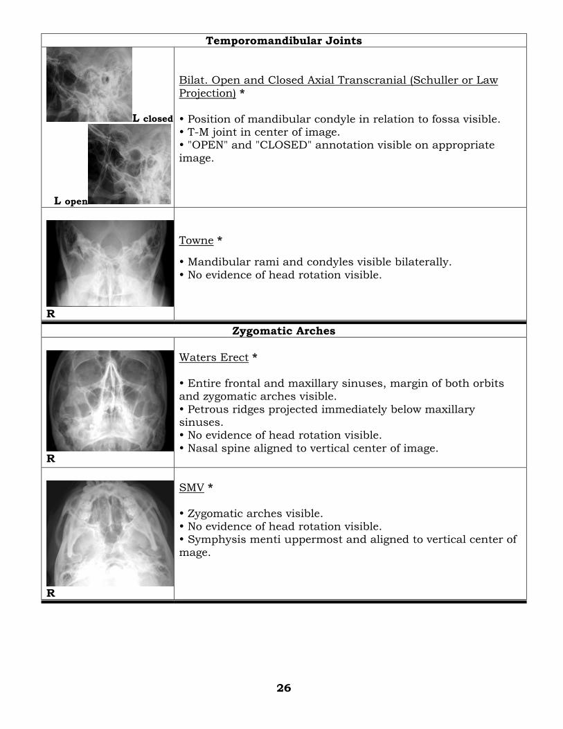
Temporomandibular Joints
L closed
L open
Bilat. Open and Closed Axial Transcranial (Schuller or Law
Projection) *
Position of mandibular condyle in relation to fossa visible. T-M joint in center of image. "OPEN" and "CLOSED" annotation visible on appropriate
image.
R
Towne *
Mandibular rami and condyles visible bilaterally.
No evidence of head rotation visible.
Zygomatic Arches
R
Waters Erect *
Entire frontal and maxillary sinuses, margin of both orbits and zygomatic arches visible.
Petrous ridges projected immediately below maxillary sinuses. No evidence of head rotation visible.
Nasal spine aligned to vertical center of image.
R
SMV *
Zygomatic arches visible. No evidence of head rotation visible. Symphysis menti uppermost and aligned to vertical center of
mage.
26
Spines
Cervical Spine
L
AP with 15° Cephalic Angle *
Vertebrae from C3 to T2 visible. Inferior border of symphysis menti superimposed over inferior border of occipital bone.
Intervertebral disc spaces open. No evidence of rotation.
Spine aligned to vertical midline of image.
R
AP Open-Mouth *
C1 and most of C2 including odontoid process visible within open mouth. Inferior margins of upper teeth and base of skull
superimposed. No evidence of rotation.
If open-mouth AP unsuccessful, then a Fuchs Method or "Wagging" jaw maneuver is to be done.
L
Lateral *
All seven cervical vertebrae visible including articulation with T1. A separate radiograph of cervicothoracic region (Swimmers) is required if C7-T1 articulation not visualized.
Sella turcica included to insure visualization of clivus (area between dorsum sellae and foramen magnum). Air filled Pharynx and trachea visible.
No evidence of rotation.
L
Swimmers *routine only if C7-T1 not seen on Lateral
Vertebrae from C1 to T3 visible especially C7 and T1. Air filled Pharynx and trachea visible.
No evidence of rotation.
27
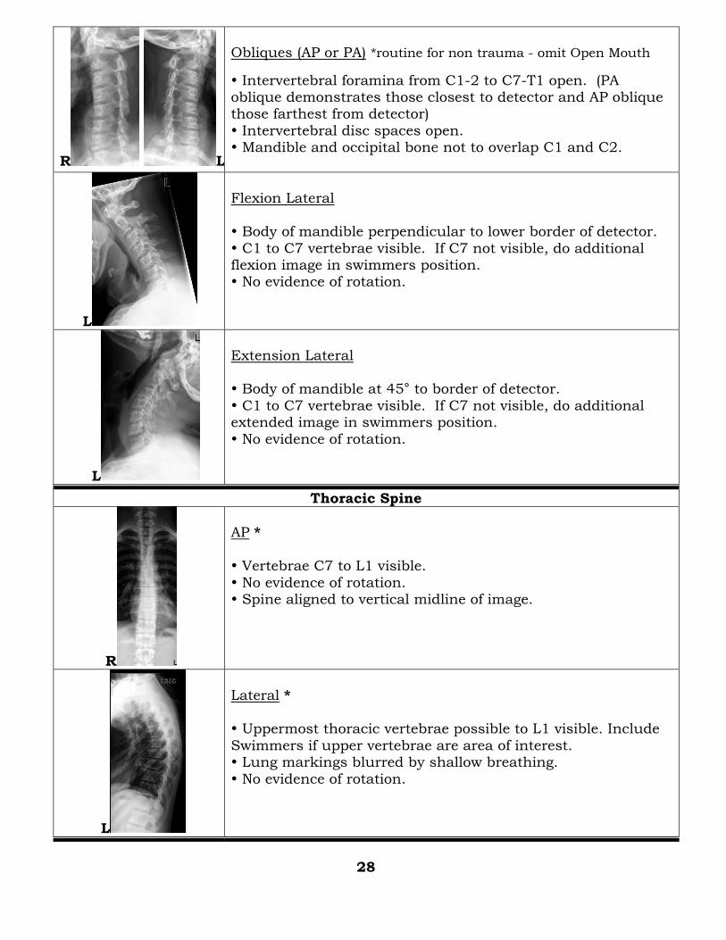
R L
Obliques (AP or PA) *routine for non trauma - omit Open Mouth
Intervertebral foramina from C1-2 to C7-T1 open. (PA oblique demonstrates those closest to detector and AP oblique those farthest from detector)
Intervertebral disc spaces open. Mandible and occipital bone not to overlap C1 and C2.
L
Flexion Lateral Body of mandible perpendicular to lower border of detector.
C1 to C7 vertebrae visible. If C7 not visible, do additional flexion image in swimmers position. No evidence of rotation.
L
Extension Lateral Body of mandible at 45° to border of detector.
C1 to C7 vertebrae visible. If C7 not visible, do additional extended image in swimmers position.
No evidence of rotation.
Thoracic Spine
R
AP *
Vertebrae C7 to L1 visible.
No evidence of rotation. Spine aligned to vertical midline of image.
L
Lateral * Uppermost thoracic vertebrae possible to L1 visible. Include
Swimmers if upper vertebrae are area of interest. Lung markings blurred by shallow breathing.
No evidence of rotation.
28
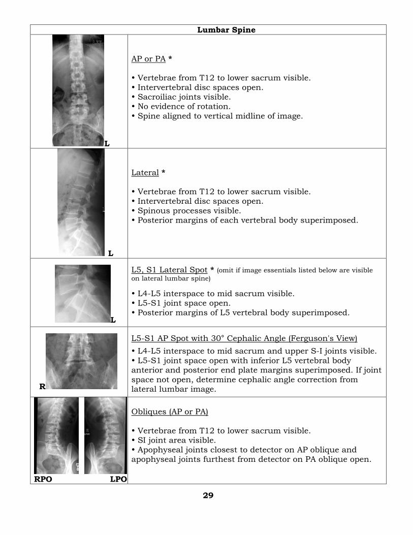
Lumbar Spine
L
AP or PA *
Vertebrae from T12 to lower sacrum visible.
Intervertebral disc spaces open. Sacroiliac joints visible. No evidence of rotation.
Spine aligned to vertical midline of image.
L
Lateral *
Vertebrae from T12 to lower sacrum visible. Intervertebral disc spaces open.
Spinous processes visible. Posterior margins of each vertebral body superimposed.
L
L5, S1 Lateral Spot * (omit if image essentials listed below are visible
on lateral lumbar spine)
L4-L5 interspace to mid sacrum visible. L5-S1 joint space open.
Posterior margins of L5 vertebral body superimposed.
R
L5-S1 AP Spot with 30° Cephalic Angle (Ferguson's View)
L4-L5 interspace to mid sacrum and upper S-I joints visible.
L5-S1 joint space open with inferior L5 vertebral body anterior and posterior end plate margins superimposed. If joint
space not open, determine cephalic angle correction from lateral lumbar image.
RPO LPO
Obliques (AP or PA)
Vertebrae from T12 to lower sacrum visible. SI joint area visible.
Apophyseal joints closest to detector on AP oblique and apophyseal joints furthest from detector on PA oblique open.
29
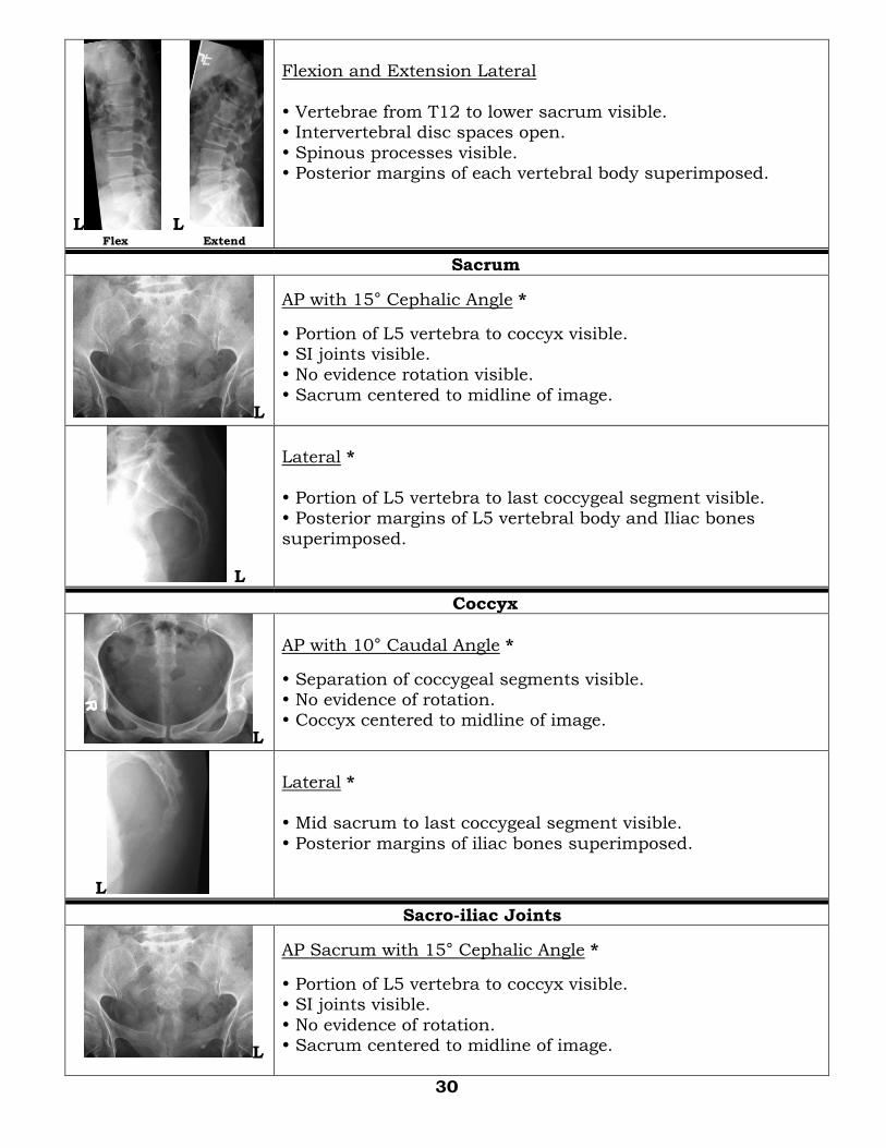
L L Flex Extend
Flexion and Extension Lateral
Vertebrae from T12 to lower sacrum visible. Intervertebral disc spaces open.
Spinous processes visible. Posterior margins of each vertebral body superimposed.
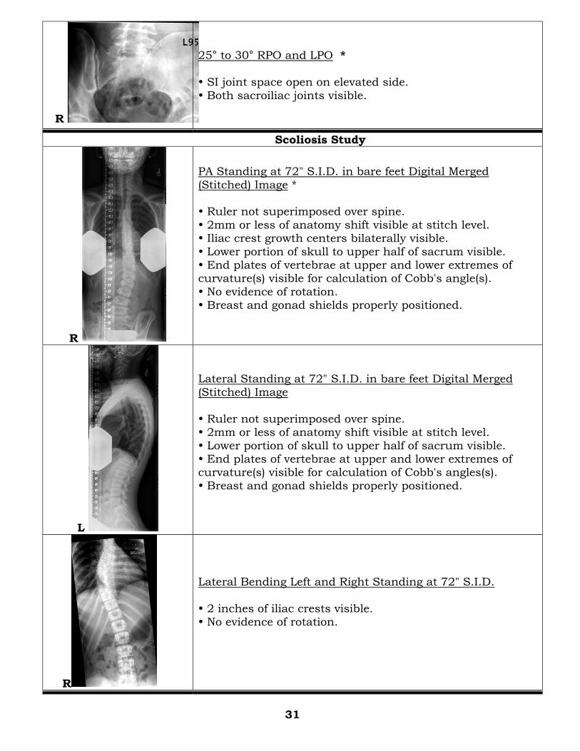
Sacrum
L
AP with 15° Cephalic Angle *
Portion of L5 vertebra to coccyx visible. SI joints visible. No evidence rotation visible.
Sacrum centered to midline of image.
L
Lateral *
Portion of L5 vertebra to last coccygeal segment visible. Posterior margins of L5 vertebral body and Iliac bones
superimposed.
Coccyx
L
AP with 10° Caudal Angle *
Separation of coccygeal segments visible. No evidence of rotation. Coccyx centered to midline of image.
L
Lateral * Mid sacrum to last coccygeal segment visible.
Posterior margins of iliac bones superimposed.
Sacro-iliac Joints
L
AP Sacrum with 15° Cephalic Angle *
Portion of L5 vertebra to coccyx visible. SI joints visible.
No evidence of rotation. Sacrum centered to midline of image.
30
R
25° to 30° RPO and LPO *
SI joint space open on elevated side.
Both sacroiliac joints visible.
Scoliosis Study
R
PA Standing at 72" S.I.D. in bare feet Digital Merged
(Stitched) Image * Ruler not superimposed over spine.
2mm or less of anatomy shift visible at stitch level. Iliac crest growth centers bilaterally visible.
Lower portion of skull to upper half of sacrum visible. End plates of vertebrae at upper and lower extremes of curvature(s) visible for calculation of Cobb's angle(s).
No evidence of rotation. Breast and gonad shields properly positioned.
L
Lateral Standing at 72" S.I.D. in bare feet Digital Merged (Stitched) Image
Ruler not superimposed over spine. 2mm or less of anatomy shift visible at stitch level.
Lower portion of skull to upper half of sacrum visible. End plates of vertebrae at upper and lower extremes of curvature(s) visible for calculation of Cobb's angles(s).
Breast and gonad shields properly positioned.
R
Lateral Bending Left and Right Standing at 72" S.I.D.
2 inches of iliac crests visible. No evidence of rotation.
31
Thorax
Chest (lungs)
L
PA Erect at 72" S.I.D. *
Entire lung fields from apices to both costophrenic angles visible. Ten posterior ribs above diaphragm visible.
No evidence of rotation. No blurring of heart or diaphragm.
Thorax aligned with image midline.
L
Left Lateral Erect at 72" S.I.D. *
Entire lung field from apices to costophrenic angles visible. All of sternum to posterior ribs visible.
No evidence of rotation. No blurring of heart or diaphragm.
R
AP Supine or Semi-erect at 48" S.I.D. (only if upright not possible)
Entire lung fields from apices to both costophrenic angles visible. No evidence of rotation.
No blurring of heart or diaphragm. Thorax aligned with image midline. Annotation must be visible stating position and SID.
Right Lateral Decubitus (right side down)
Lateral Decubitus Entire side of interest visible;
- lower side if for pleural effusion, - elevated side if for pneumothorax. No evidence of rotation.
Annotation indicating side down visible.
32
L
AP Lordotic
Apices and lungs to costophrenic angles visible. Clavicles projected superior to lungs.
Thorax aligned with image midline. No evidence of rotation.
L
PA Obliques (RAO and LAO) Erect at 72" S.I.D.
Entire lung fields from apices to both costophrenic angles visible.
No blurring of heart or diaphragm.
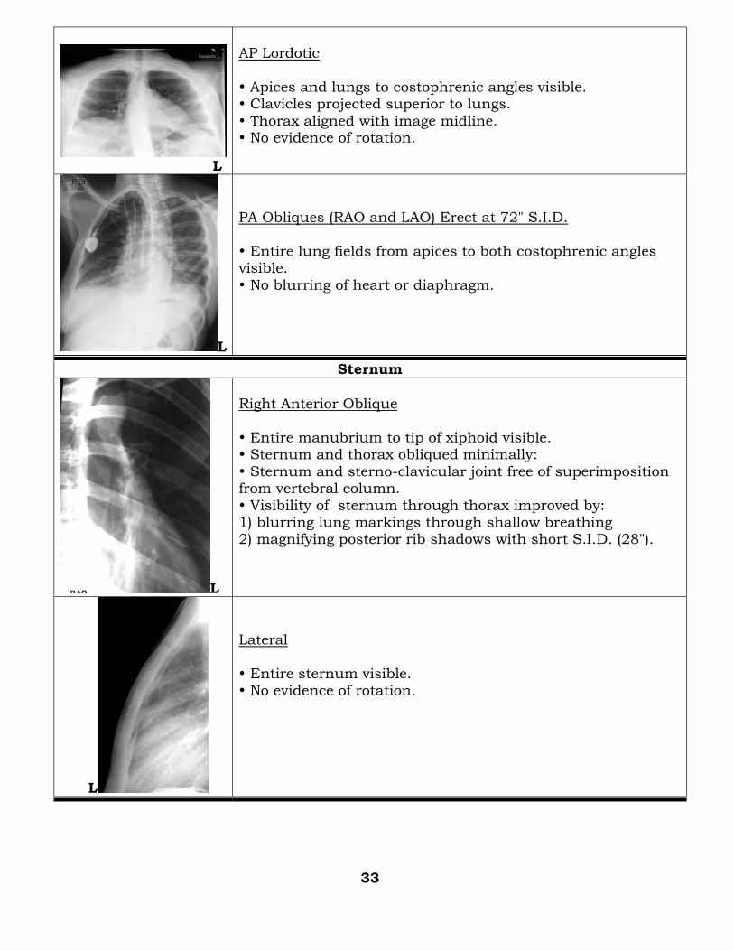
Sternum
L
Right Anterior Oblique
Entire manubrium to tip of xiphoid visible. Sternum and thorax obliqued minimally:
Sternum and sterno-clavicular joint free of superimposition from vertebral column.
Visibility of sternum through thorax improved by: 1) blurring lung markings through shallow breathing 2) magnifying posterior rib shadows with short S.I.D. (28").
L
Lateral
Entire sternum visible. No evidence of rotation.
33
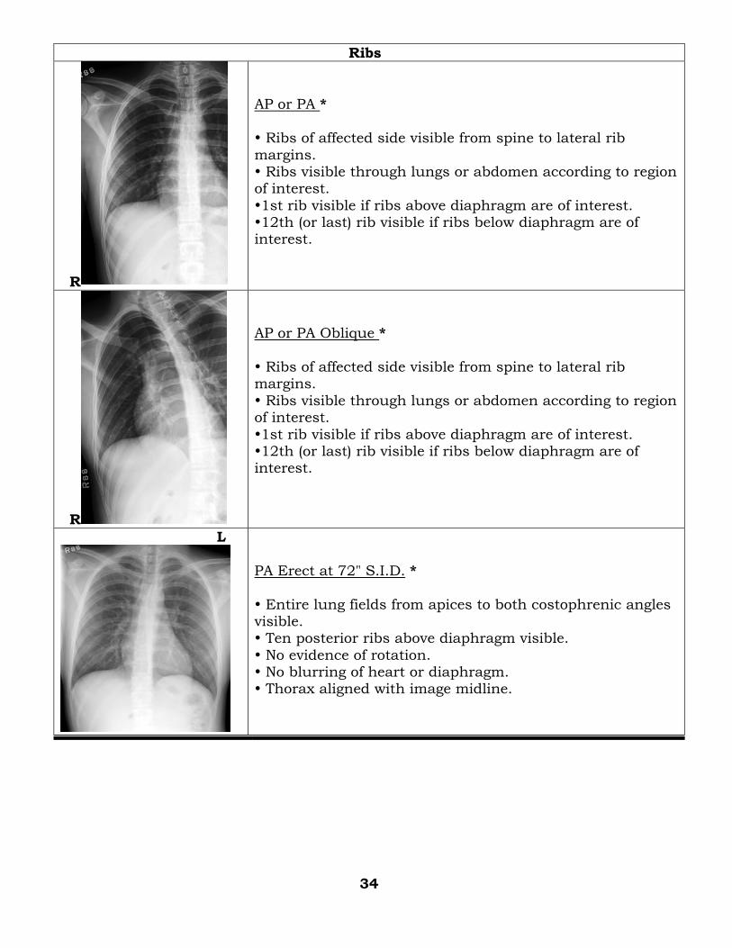
Ribs
R
AP or PA *
Ribs of affected side visible from spine to lateral rib
margins. Ribs visible through lungs or abdomen according to region of interest.
1st rib visible if ribs above diaphragm are of interest. 12th (or last) rib visible if ribs below diaphragm are of interest.
R
AP or PA Oblique *
Ribs of affected side visible from spine to lateral rib margins.
Ribs visible through lungs or abdomen according to region of interest.
1st rib visible if ribs above diaphragm are of interest. 12th (or last) rib visible if ribs below diaphragm are of interest.
L
PA Erect at 72" S.I.D. *
Entire lung fields from apices to both costophrenic angles visible. Ten posterior ribs above diaphragm visible.
No evidence of rotation. No blurring of heart or diaphragm. Thorax aligned with image midline.
34
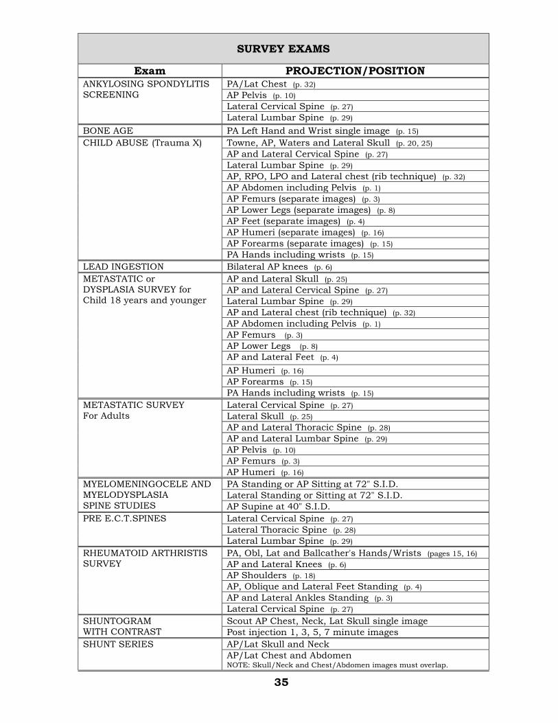
SURVEY EXAMS
Exam PROJECTION/POSITION ANKYLOSING SPONDYLITIS
SCREENING
PA/Lat Chest (p. 32)
AP Pelvis (p. 10)
Lateral Cervical Spine (p. 27)
Lateral Lumbar Spine (p. 29)
BONE AGE PA Left Hand and Wrist single image (p. 15)
CHILD ABUSE (Trauma X)
Towne, AP, Waters and Lateral Skull (p. 20, 25)
AP and Lateral Cervical Spine (p. 27)
Lateral Lumbar Spine (p. 29)
AP, RPO, LPO and Lateral chest (rib technique) (p. 32)
AP Abdomen including Pelvis (p. 1)
AP Femurs (separate images) (p. 3)
AP Lower Legs (separate images) (p. 8)
AP Feet (separate images) (p. 4)
AP Humeri (separate images) (p. 16)
AP Forearms (separate images) (p. 15)
PA Hands including wrists (p. 15)
LEAD INGESTION Bilateral AP knees (p. 6)
METASTATIC or DYSPLASIA SURVEY for
Child 18 years and younger
AP and Lateral Skull (p. 25)
AP and Lateral Cervical Spine (p. 27)
Lateral Lumbar Spine (p. 29)
AP and Lateral chest (rib technique) (p. 32)
AP Abdomen including Pelvis (p. 1)
AP Femurs (p. 3)
AP Lower Legs (p. 8)
AP and Lateral Feet (p. 4)
AP Humeri (p. 16)
AP Forearms (p. 15)
PA Hands including wrists (p. 15)
METASTATIC SURVEY
For Adults
Lateral Cervical Spine (p. 27)
Lateral Skull (p. 25)
AP and Lateral Thoracic Spine (p. 28)
AP and Lateral Lumbar Spine (p. 29)
AP Pelvis (p. 10)
AP Femurs (p. 3)
AP Humeri (p. 16)
MYELOMENINGOCELE AND
MYELODYSPLASIA
SPINE STUDIES
PA Standing or AP Sitting at 72" S.I.D.
Lateral Standing or Sitting at 72" S.I.D.
AP Supine at 40" S.I.D.
PRE E.C.T.SPINES Lateral Cervical Spine (p. 27)
Lateral Thoracic Spine (p. 28)
Lateral Lumbar Spine (p. 29)
RHEUMATOID ARTHRISTIS SURVEY
PA, Obl, Lat and Ballcather's Hands/Wrists (pages 15, 16)
AP and Lateral Knees (p. 6)
AP Shoulders (p. 18)
AP, Oblique and Lateral Feet Standing (p. 4)
AP and Lateral Ankles Standing (p. 3)
Lateral Cervical Spine (p. 27)
SHUNTOGRAM
WITH CONTRAST
Scout AP Chest, Neck, Lat Skull single image
Post injection 1, 3, 5, 7 minute images
SHUNT SERIES AP/Lat Skull and Neck
AP/Lat Chest and Abdomen NOTE: Skull/Neck and Chest/Abdomen images must overlap.
35
Radiographic Positioning Textbooks
Textbook of Radiographic Positioning and Related Anatomy
Kenneth L. Bontrager, MA, RT(R)
Mosby, Inc
Positioning in Radiography
K. C. Clark, M.B.E. Intercontinental Medical Book Corporation
Merrill's Atlas of Radiographic Positions and Radiologic Procedures Philip W. Ballinger, MS, RT(R), FAERS Eugene D. Frank, MA, RT(R), FASRT
Mosby, Inc
Orthopaedist's Guide to Plain Film Imaging Helene Pavlov, MD, FACR
Michele Burke, BS, RT Mary Giesa, RT
Kathleen R. Seager, BS, RT Edward T. White, RT
Thieme Medical Publishers, Inc.