Dark and Its Optical Network Applications - CESNET · PDF fileand Its Optical Network...
18
© National Institute of Information and Communications Technology Hiroaki Harai ([email protected]) Director at Network Architecture Lab. National Institute of Information and Communications Technology Koganei, Tokyo, Japan Sep 15, 2014 8 th CEF Networks Workshop 1/18 Dark Fibre Testbed in Japan and Its Optical Network Applications
Transcript of Dark and Its Optical Network Applications - CESNET · PDF fileand Its Optical Network...

© National Institute of Information and Communications Technology
Hiroaki Harai ([email protected])Director at Network Architecture Lab.
National Institute of Information and Communications Technology Koganei, Tokyo, Japan
Sep 15, 20148th CEF Networks Workshop
1/18
Dark Fibre Testbed in Japan and Its Optical Network
Applications

© National Institute of Information and Communications Technology
Contents of This Talk JGN‐X ‐ A nation‐wide R&D network testbed Dark fibres on JGN‐X Advanced optical applications on the dark fibres JGN‐X useful facilities for optical network experiments Conclusion and Next step
2/18

© National Institute of Information and Communications Technology
Where is Japan? –JGN‐X International Circuits
Tokyo
CA*net4(Canada)
SURFnet(Netherland)
Internet2(USA)
NLR(USA)
MREN(USA)
AARNet(Australia)
IEEAF(USA)
UKLight(UK)
ThaiSarn(Thailand)
SingAREN(Singapore)
StarLight(USA)TransPAC3
(USA)
LA
HK
GEANT(Europe)
APAN(Asia)
PacificWave(USA)
CERNET(China)
CSTNET(China)
BKKUniNet(Thailand)
KOREN(Korea)
KR
SG
US‐JP line : Tokyo‐Los Angeles, 10GbpsKR‐JP line (APII) : Tokyo‐Seoul, 10GbpsHK‐JP line : Tokyo‐Hong Kong, 10GbpsHK‐SG line : Hong Kong – Singapore 2.4GbpsSG‐TH line : Singapore –Thailand 1Gbps
TEIN4(Asia, Europe)
http://www.jgn.nict.go.jp/ 3/18

JGN-X Network (planned for Oct. 2014)Realizing multiple New Generation Network Planes on virtual JGN‐X network. Also made it available to interconnect with other Testbeds.
FukuokaHiroshima
Okayama
Sendai
NICT Koganei
SouthKorea
USA Thailand Singapore HongKong
Bandwidth International
Wireless Testbed
Kanazawa
Kagawa
Okinawa
Nagoya
Kochi
DCNDCN
DCNDCN plane
OFOF
OFOF
OFOpenFlow plane
VN
VN
Virtual Node planeVN
VN
Optical TestbedWireless Testbed
VLAN-based testbed network
Osaka
Iwate
Tokyo
Sapporo
100G10G
DF
VN Virtual Node
OF Openflow
DCN DCNEx
1GVirtual Storage
StarBED
Japan- USA: 10GJapan - Korea: 10GJapan – Hong Kong: 10GHong Kong - Singapore 2.4GSingapore - Thailand: 1G
Optical TestbedKoganei -- OtemachiOtemachi -- Hakusan
DCNVN
OF
VN OF
DCNVN
OF
VN
OF
OF OF OF
VN
OF
OF
VN
OF
DCNVN
OF
OF 4/18

© National Institute of Information and Communications Technology
Dark Fibres
G.652 single mode fibres (SMFs) are installed16 SMFs (45km, < 20dB@1550nm) Koganei<‐> Otemachi4 SMFs (12km, < 12dB@1550nm) Otemachi<‐>Hakusan)
Total length approximate 768 km No amplifiers (Installed by users)
HakusanTOKYO
KoganeiTOKYO
OtematchiTOKYO
SMF 16 fibers (2 fibers x 8) SMF 4 fibers (2 fibers x 2)
(Approx. 45km)
(Approx12km)
http://www.jgn.nict.go.jp/ 5/18

© National Institute of Information and Communications Technology
Advanced Applications for Dark Fibre Testbed Time and Frequency Transfer Quantum Communications (Quantum Key Distribution Network) 1.28 Tbps Optical Packet Transmission and Switching System Optical Packet and Circuit Integrated Network Commercial 100Gigabit Ethernet Line
6/18

© National Institute of Information and Communications Technology
Highly Stable Time and Frequency (T&F) Transfer
NICT has primary responsibility of National T&F Metrology in Japan. Japan Standard Time, Atomic Frequency Standards, Satellite Link, etc..
New technique for T&F transfer using optical fiber linkActive cancellation of imposed fiber noise during transmission
Direct frequency comparison of two high accurate optical clocksDetected a few Hz difference due to the elevation (relativistic effect)
Source: Space‐Time Standards Laboratory of NICT
7/18
8
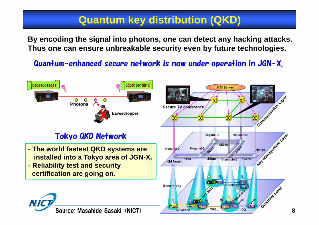
Quantum key distribution (QKD)
Photons
Eavesdropper X
By encoding the signal into photons, one can detect any hacking attacks. Thus one can ensure unbreakable security even by future technologies.
- The world fastest QKD systems are installed into a Tokyo area of JGN-X.
- Reliability test and security certification are going on.
Tokyo QKD Network
Quantum-enhanced secure network is now under operation in JGN-X.
Source: Masahide Sasaki (NICT)

© National Institute of Information and Communications Technology
Optical Packet Transmission & Switching System
Demonstration of optical packet switching and buffering for 1.28 Tbit/s (64ch×20 Gbit/s DQPSK) optical packets after transmitting over 100‐km long field fiber (JGN).
~100 km
1.28 Tbit/sOptical Packets 2x2 OPS
TX1
TX2
RX
RXKOGANEI KOGANEIOTEMACHI (Loop-back)
Transmitter
QPSK(Data 1)LN-IM
TX1
TX2
Label Generator
QPSK(Data 2)LN-IM
13
5
63
24
6
64
64ch, 50-GHz spacing64 x 10 Gbaud-DQPSK
1.28Tbit/s WDM/DQPSK packets
Ref. S. Shinada et al., Optics Express 2011.Source: Satoshi Shinada (NICT)
with label-A
with label-B
2x1 Buffer with 3-FDLs(for label-B)
2x2 OPSLabel Processor Buffer Manager
1x4 PLZTSwitch
RX
RX
1x2 PLZTSwitch
1x2 PLZTSwitch
Electro-optic switch with low-polarization-dependence
1x4 PLZTSwitch
(for label-A)
9/18

© National Institute of Information and Communications Technology
Optical Packet Trans. & Switching System (Cont’d)
Low-polarization-dependence OPS system succeeded in handling optical packets with time-varying polarization (after field-fiber transmission).
DGD/ PMD
100-km field fiber in JGN testbed
1530 1540 1550 1560 1570
2.5
2.0
1.5
1.0
0.5
60
45
30
15
0
Tim
e [m
in]
Wavelength [nm]
DGD [ps]
1530 1540 1550 1560 1570
60
45
30
15
0
Tim
e [m
in]
Wavelength [nm]
2.5
2.0
1.5
1.0
0.5
DGD [ps]After Transmitter
-45 -43 -41 -39 -37 -35 -33
-4
-10
-9-8
-7
-6
-5
Power [dBm]
Log(
BE
R)
Back to Back(w/o Transmissionand OPS process)
1540 1550 1560
1540 1550 1560
Wavelength [nm]
64 ch(50-GHz spacing)
WDM Packets
TX-2
< 7 dB (time-varying)
After OPS process
TX-1
Out
put [
5 dB
/div
.]O
utpu
t Pow
er [5
dB/
div.
]
After Field Transmissionand OPS process
100-km bobbin fiber on the benchSpectra of WDM packets Bit Error Rate (64ch x I/Q)
1.28 Tbit/s (64ch x10 Gbaud DQPSK)
10/18Ref. S. Shinada et al., Optics Express 2011.Source: Satoshi Shinada (NICT)

© National Institute of Information and Communications Technology
Optical Packet & Circuit Integrated Network User view: A “high‐speed, inexpensive” service and
“low delay, low data‐loss” service on a single optical network Network provider view: Large switch capacity (>100Gbps
Optical Packet), energy saving, and flexible & efficient resource use under a simple control
packets circuits
Sensors, tags
Packet sequence
11/18
© National Institute of Information and Communications Technology
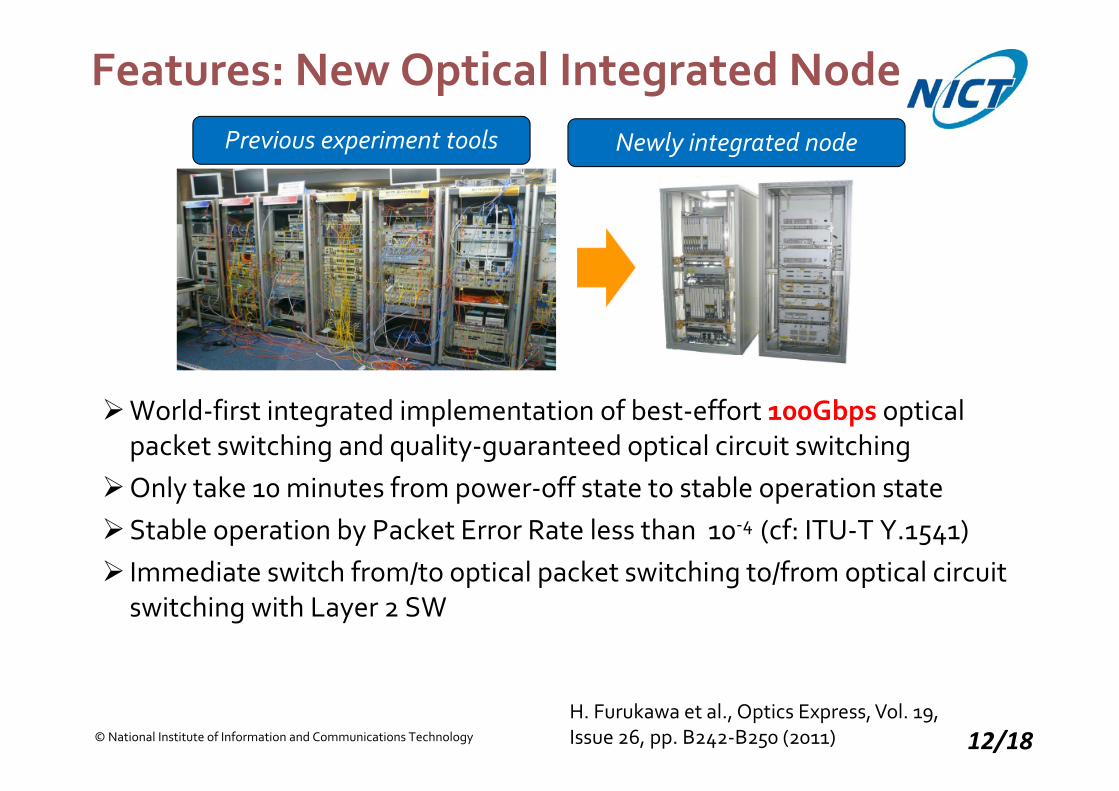
Features: New Optical Integrated Node
World‐first integrated implementation of best‐effort 100Gbps optical packet switching and quality‐guaranteed optical circuit switching
Only take 10 minutes from power‐off state to stable operation stateStable operation by Packet Error Rate less than 10‐4 (cf: ITU‐T Y.1541) Immediate switch from/to optical packet switching to/from optical circuit
switching with Layer 2 SW
Previous experiment tools Newly integrated node
H. Furukawa et al., Optics Express, Vol. 19, Issue 26, pp. B242‐B250 (2011) 12/18

© National Institute of Information and Communications Technology
Optical Integrate Node 100GHz spacing, 40Wavelengths (1531.9—1563.05nm)
For packet switching, only 1 of 10 wavelengths is converted into electric signals for header processing
Performance of packet error rate is compliant with ITU‐T Y.1541
Circuits Wavelengths 30 C‐bands
Clients 7 10BASE‐LR Can insert other alien wavelengths
Net 7 OTU2e
Packets Wavelengths 10 C‐bands
Clients 10 10BASE‐LR 64‐9,604 byte frame
Net 1 100Gbps
Switching Layer 3
13/18

© National Institute of Information and Communications Technology
Two “Optical Packet & Circuit Nodes” Connected to JGN‐X at InteropTokyo 2011
14/18

© National Institute of Information and Communications Technology
Make OPCInet Stable, Operational, and SDN‐capable 5‐hop, 244 km 100Gbps optical packet switching 8 fiber‐delay‐line buffer embedded Longest prefix matching of optical packet header confirmed Management system connected Optical testbed experiments (below)
Our lab net is accessible to the Internet via OPCInodes
OpenFlow/OPCI node interwork on JGN‐X (RISE)
T. Miyazawa et al., SDN Workshop at IEEE Globecom 2013.H. Harai et al, IEEE/OSA JLT, 32 (16), 2751‐2759 (2014).
15/18

© National Institute of Information and Communications Technology
Other JGN‐X Facilities for Optical Network R&DRISE ( Research Infrastructure for large‐Scale network Experiments) OpenFlow network environment Ver. 2.0: multi‐user model
(April 2012) OpenFlow‐based user‐slices
in which users can use their own controllers
Virtualized IP Services VMs, virtual routers, 4Gbps FC
capable storages Tailor‐made network computing
environment with computers, storages, and networks for each user slice
Source: Eiji Kawai 16/18

© National Institute of Information and Communications Technology
Conclusion JGN‐X: nation‐wide R&D network testbed in Japan Dark fibres installed in Tokyo for advanced application
verificationTime and Frequency TransferQKD (Quantum key distribution) network 1.28Tbps Optical Packet Transmission and Switching SystemOPCInet (Optical packet & circuit integrated network)
Users want a variety of services (dark fibre, L2, OpenFlow, VM, …) for advanced trials
We are promoting OPCI net into the deployment stage on R&D network testbed
Next page is final. 17/18

© National Institute of Information and Communications Technology
Next Steps: OPCInet Deployment
Future JGN
We are promoting OPCInet deployment in R&D network testbed
18/18

![The Emerging Optical Control Plane - fujitsu.com · (ASON) [2]. In general, the ITU-T has defined the architecture and requirements for an optical control plane, whereas the IETF](https://static.fdocuments.in/doc/165x107/5c019a9309d3f2377a8d8969/the-emerging-optical-control-plane-ason-2-in-general-the-itu-t-has-defined.jpg)