
DAQSTATION CX1000 User's Manual - Yokogawa …cdn2.us.yokogawa.com/IM04L31A01-03E_060.pdf · Manual...
414
User’s Manual Yokogawa Electric Corporation Model CX1000/CX1006/CX1200/CX1206 DAQSTATION CX1000 IM 04L31A01-03E 6th Edition
Transcript of DAQSTATION CX1000 User's Manual - Yokogawa …cdn2.us.yokogawa.com/IM04L31A01-03E_060.pdf · Manual...

User’sManual
Yokogawa Electric Corporation
Model CX1000/CX1006/CX1200/CX1206
DAQSTATION CX1000
IM 04L31A01-03E6th Edition

iIM 04L31A01-03E
6th Edition : June 2010 (YK)
All Rights Reserved, Copyright © 2002 Yokogawa Electric Corporation
Thank you for purchasing the CX1000. This manual describes the functions (excludingthe communications functions), installation and wiring procedures, operating procedures,and handling precautions of the CX1000. To ensure correct use, please read thismanual thoroughly before beginning operation. The following manuals are also providedin addition to this manual. Read them along with this manual.Electronic Manuals Provided on the Accompanying CD-ROM
Manual Title Manual No. Description
CX1000/CX2000 IM 04L31A01-17E Describes the communications functions of theCommunications Interface CX1000/CX2000 using the Ethernet/serial interface.User’s Manual
Paper Manuals
Manual Title Manual No. Description
CX1000 Opration Guide IM 04L31A01-04E A guide providing simple explanations ofcontrol-related operations for the CX1000(includes a chart of setting values).
CX1000 Installation and IM 04L31A01-73E Describes concisely the installationConnection Guide procedures and wiring procedures of the CX1000.
Precautions on the Use of IM 04L31A01-72E Precautions regarding the use of the CX1000/CX2000.the CX1000/CX2000 The same information is written on pages ii and iii of
this user’s manual.
CX1000/CX2000 Control of IM 04L31A01-91C Gives a description of pollution control.Pollution Caused by the Product
DAQSTANDARD ManualsAll manuals other than IM 04L41B01-66EN are contained in the DAQSTANDARD CD.
Manual Title Manual No.
DAQSTANDARD Data Viewer User’s Manual IM 04L41B01-63EN
DAQSTANDARD Hardware Configurator User’s Manual IM 04L41B01-64EN
Installing DAQSTANDARD IM 04L41B01-66EN
Notes• This manual describes the CX1000, style number “S3.”• The contents of this manual are subject to change without prior notice as a result of
continuing improvements to the instrument’s performance and functions.• Every effort has been made in the preparation of this manual to ensure the accuracy of
its contents. However, should you have any questions or find any errors, please contactyour nearest YOKOGAWA dealer.
• Copying or reproducing all or any part of the contents of this manual without thepermission of Yokogawa Electric Corporation is strictly prohibited.
• The TCP/IP software of this product and the document concerning the TCP/IPsoftware have been developed/created by YOKOGAWA based on the BSDNetworking Software, Release 1 that has been licensed from the Regents of theUniversity of California.
Trademarks• vigilantplant, DAQSTATION, and Daqstation are registered trademarks of Yokogawa
Electric Corporation.• Microsoft and Windows are registered trademarks or trademarks of Microsoft
Corporation in the United States and/or other countries.• Adobe and Acrobat are registered trademarks or trademarks of Adobe Systems
Incorporated.• Company and product names that appear in this manual are registered trademarks or
trademarks of their respective holders.• The company and product names used in this manual are not accompanied by
registered trademark or trademark symbols (® and ™).Revisions
1st Edition March 2002 4th Edition November 20032nd Edition April 2002 5th Edition May 20073rd Edition June 2003 6th Edition June 2010

ii IM 04L31A01-03E
Safety Precautions
About This Manual• This manual should be read by the end user.
• Read this manual thoroughly and have a clear understanding of the product before operation.• This manual explains the functions of the product. YOKOGAWA does not guarantee that the product will suit
a particular purpose of the user.
• Under absolutely no circumstances may the contents of this manual be transcribed or copied, in part or inwhole, without permission.
• The contents of this manual are subject to change without prior notice.
• Every effort has been made in the preparation of this manual to ensure the accuracy of its contents.However, should you have any questions or find any errors or omissions, please contact your nearestYOKOGAWA dealer.
Precautions Related to the Protection, Safety, and Alteration of the Product• The following safety symbols are used on the product and in this manual.
“Handle with care.” (To avoid injury, death of personnel or damage to the instrument, the operatormust refer to the explanation in the manual.)
Functional ground terminal. (Do not use this terminal as a protective ground terminal.)
Protective grounding terminal
Alternating current
Direct current
• For the protection and safe use of the product and the system controlled by it, be sure to follow theinstructions and precautions on safety that are stated in this manual whenever you handle the product. Takespecial note that if you handle the product in a manner that violate these instructions, the protection
functionality of the product may be damaged or impaired. In such cases, YOKOGAWA does not guaranteethe quality, performance, function, and safety of the product.
• When installing protection and/or safety circuits such as lightning protection devices and equipment for the
product and control system or designing or installing separate protection and/or safety circuits for fool-proofdesign and fail-safe design of the processes and lines that use the product and the control system, the usershould implement these using additional devices and equipment.
• If you are replacing parts or consumable items of the product, make sure to use parts specified byYOKOGAWA.
• This product is not designed or manufactured to be used in critical applications that directly affect or threaten
human lives. Such applications include nuclear power equipment, devices using radioactivity, railwayfacilities, aviation equipment, air navigation facilities, aviation facilities, and medical equipment. If so used, itis the user’s responsibility to include in the system additional equipment and devices that ensure personnel
safety.• Do not modify this product.• The CX is designed for indoor use.

iiiIM 04L31A01-03E
WARNINGPower Supply
Ensure that the source voltage matches the voltage of the power supply before turning ON the power.Protective Grounding
Make sure to connect the protective grounding to prevent electric shock before turning ON the power.Necessity of Protective Grounding
Never cut off the internal or external protective earth wire or disconnect the wiring of the protective
earth terminal. Doing so invalidates the protective functions of the instrument and poses a potentialshock hazard.
Defect of Protective GroundingDo not operate the instrument if the protective earth or fuse might be defective. Make sure to checkthem before operation.
Do Not Operate in an Explosive AtmosphereDo not operate the instrument in the presence of flammable liquids or vapors. Operation in suchenvironments constitutes a safety hazard.
Do Not Remove CoversThe cover should be removed by YOKOGAWA’s qualified personnel only. Opening the cover isdangerous, because some areas inside the instrument have high voltages.
External ConnectionConnect the protective grounding before connecting to the item under measurement or to an externalcontrol unit.
Damage to the Protective StructureOperating the CX1000 in a manner not described in this manual may damage its protective structure.
Exemption from Responsibility• YOKOGAWA makes no warranties regarding the product except those stated in the WARRANTY that is
provided separately.• YOKOGAWA assumes no liability to any party for any loss or damage, direct or indirect, caused by the user
or any unpredictable defect of the product.
Handling Precautions of the Software• YOKOGAWA makes no warranties regarding the software accompanying this product except those stated in
the WARRANTY that is provided separately.• Use the software on a single PC.
• You must purchase another copy of the software, if you are to use the software on another PC.• Copying the software for any purposes other than backup is strictly prohibited.• Please store the original media containing the software in a safe place.
• Reverse engineering, such as decompiling of the software, is strictly prohibited.• No portion of the software supplied by YOKOGAWA may be transferred, exchanged, sublet, or leased for
use by any third party without prior permission by YOKOGAWA.
Safety Precautions

iv IM 04L31A01-03E
Checking the Contents of the Package
Unpack the box and check the contents before operating the instrument. If some of thecontents are not correct or missing or if there is physical damage, contact the dealer
from which you purchased them.
CX1000When you open the operation cover on the front panel, a name plate is located on theback side of the cover. Check that the model name and suffix code given on the nameplate on the rear panel match those on the order.
NO
SUFFIXMODEL STYLE
STYLE
Open the operationcover
MODEL and SUFFIX
/A6/A6R/A4F/A4FR
/M1/N2/P1/PG1/PG2/BT1
–1–2–3–5
–0–1–2
–1–2
CX1000CX1006CX1200CX1206Externalstoragemedium
*1 Only one can be specified at once on the CX1000 and CX1006.
Model Suffix Code Optional Code Description
Communicationinterface
Displayed language
Options
Number of internal control loops: 0, number of inputs for measurement: 0 ch
Number of internal control loops: 2, number of inputs for measurement: 6 chFloppy disk100MB Zip diskATA flash memory card (Compact flash and adapter)250MB Zip diskEthernet
Ethernet + RS-232 serial interface port
Ethernet + RS-422A/485 serial interface portJapaneseEnglish
6 measurement alarm outputs*1
6 measurement alarm output, 8 remote inputs*1
4 measurement alarm outputs, 1 FAIL output, 1 memory end output*1
4 measurement alarm outputs, 1 FAIL output, 1 memory end output,8 remote inputs*1
Computation functionThree-wire isolated RTD (input for measurement)24-VDC/AC power supply drivenProgram control (number of program patterns: 4)*2
Program control (number of program patterns: 30)*2
*2 Either one can be specified on the CX1200 and CX1206.
Number of internal control loops: 0, number of inputs for measurement: 6 chNumber of internal control loops: 2, number of inputs for measurement: 0 ch
Batch header
NO. (Instrument Number)When contacting the dealer from which you purchased the instrument, please give them
the instrument number.

vIM 04L31A01-03E
Standard AccessoriesThe standard accessories below are supplied with the instrument. Check that all
contents are present and that they are undamaged.
1 2 4 5 6 83
or
7
No. Name Part Number/Model Q’ty Note
1 Terminal screws 5 M4
2 Mounting bracket B9900BX 2 For panel mounting
3 DAQSTANDARD DXA120 1 Software for setting the CX anddisplaying data. CD-ROM used to install“DAQSTANDARD”
4 CX1000/CX2000 B8700MA 1 CD-ROM containing the PDF files of thiselectronic manual manual, the CX1000/CX2000
Communication Interface User’s Manual,DAQSTANDARD for CX User’s Manual,and other files.
5 CX1000 Operation IM 04L31A01-04E 1 A guide providing simple explanations ofGuide control-related operations for the CX1000
(includes a chart of setting values).
6 CX1000 Installation and IM 04L31A01-73E 1 Abridged paper manualConnection Guide
7 Precautions on the Use IM 04L31A01-72E 1 Paper stating the precautions.of the CX1000/CX2000CX1000/CX2000 IM 04L31A01-91C 1 Gives a description of pollution control.Control of PollutionCaused by the ProductInstalling DAQSTANDARD IM 04L41B01-66EN 1 Describes the installation procedures.
8 External storage medium A1053MP 1 100 MB Zip disk (provided only when theexternal storage medium suffix code is “-2”)
A1056MP 1 250 MB Zip disk (provided only when theexternal storage medium suffix code is “-5”)
B9968NL 1 ATA flash memory card(32 MB CF card +adapter,capacity model of CF card mayvary) provided only when the externalstorage medium suffix code is “-3”
Optional Accessories (Sold Separately)The following optional accessories are available for purchase separately. When youreceive the order, check that all contents are present and that they are undamaged.
For information and ordering, contact your nearest YOKOGAWA dealer.
Part Name Part Number/Model Q’ty Note
3.5" floppy disk 7059 00 10 2HD
Zip disk A1053MP 1 100 MBA1056MP 1 250 MB
ATA flash memory card B9968NL 1 32 MB (32 MB CF card + adapter,capacity and model of CF card mayvary)
Shunt resistance 4159 20 1 250 Ω±0.1%(for the screw terminal) 4159 21 1 100 Ω±0.1%
4159 22 1 10 Ω±0.1%
Mounting bracket B9900BX 2
Checking the Contents of the Package

vi IM 04L31A01-03E
How to Use This Manual
Structure of the ManualThis user’s manual consists of the following sections. For details on the communications
functions and the software “DAQSTANDARD” provided with the package, see therespective manuals (IM 04L31A01-17E, IM 04L41B01-63EN, and IM 04L41B01-64EN).
Chapter Title and Description
1 Explanation of FunctionsDescribes in detail the functions of the instrument. The chapters that explain theoperation of the CX1000 only describe the operating procedures. For more detailedinformation about the functions, see this chapter.
2 Installation and WiringDescribes the installation and wiring procedures of the CX1000.
3 Names of Parts, Display Modes, and Common OperationsDescribes the names of the parts of the CX1000, the basic key operations, the basicoperations carried out initially, and how to use the external storage medium drive.
4 Control Function Related Setup OperationsDescribes setup operations related to the control function that are carried out beforestarting control operations.
5 Program Control Related Setup Operations (Only on Models with the ProgramControl Option)Describes the setup operations related to program control that are carried out beforestarting control operations on models with the program control option.
6 Operations during Control OperationDescribes how to switch operation mode during control operation, how to change thesetpoints of setting mode, how to tune the control parameters, and the operations onthe program control screen (operations only on models with the option).
7 Measurement Function Related Setup OperationsDescribes how to set the PV input of the measurement function and alarms(measurement alarms).
8 Operations for Changing the Displayed ContentsDescribes how to change the operating display of both the control function and themeasurement function and the display format.
9 Data Save/Load OperationsDescribes how to write various data to the internal memory, how to save and load fromthe external storage medium, and the file operations on the external storage medium.
10 Computation and Report Function Related Operations (Only on Models with theComputation Function Option)Describes how to set and execute operations related to the computation function andreport function of the computation function option.
11 Operations of Other FunctionsDescribes the USER key, key lock, login/logout of key operation, log display, andremote input setting.
12 TroubleshootingDescribes the error messages and the troubleshooting measures of the CX1000.
13 MaintenanceDescribes periodic inspection, calibration, and recommended replacement period forworn parts.
14 SpecificationsDescribes the specifications of the CX1000.
Appendix Describes the acquisition function of measured data to the internal memory, additionalinformation on the computation and report functions, the ASCII file format, and initial settings.
Index
Note• This user’s manual covers information regarding CX1000s that have a suffix code for
language “-2” (English).
• For details on setting the displayed language, see section 3.6.

viiIM 04L31A01-03E
How to Use This Manual
Conventions Used in This ManualUnitK........ Denotes “1024.” Example: 768 KB (file size)k........ Denotes “1000.”
Safety MarkingsThe following markings are used in this manual.
Danger. Refer to corresponding location on the instrument.
This symbol appears on dangerous locations on the instrument
which require special instructions for proper handling or use. The
same symbol appears in the corresponding place in the manual to
identify those instructions.
WARNING Calls attention to actions or conditions that could cause serious
injury or death to the user, and precautions that can be taken to
prevent such occurences.
CAUTION Calls attentions to actions or conditions that could cause damage to
the instrument or user’s data, and precautions that can be taken to
prevent such occurrences.
Note Calls attention to information that is important for proper operation
of th instrument.
Symbols Used on Pages Describing Operating ProceduresOn pages that describe the operating procedures in Chapter 3 through 11, the following
symbols are used to distinguish the procedures from their explanations.[ ] ................ Indicates character strings that appear on the screen.
Example: [Space] soft key, [Volt]
Procedure This subsection contains the operating procedure used to carry out
the function described in the current section. All procedures are
written with inexperienced users in mind; experienced users may
not need to carry out all the steps.
Setup Items Describes the details of the settings and the restrictions that exist with
the operating procedure. It does not give a detailed explanation of
the function. For details on the function, see chapter 1.
the function. For details on the function, see chapter 1.
Revision History
Edition Addition and Change to Functions
5 Added the contents of IM04L31A01-05E (the user’s manual describing changes tofunctions with version 3.02 or later) to the user’s manual, and discarded IM04L31A01-05E. Added an I/O terminal diagram. Added example expressions.
6 The DAQSTANDARD is revised.

viii IM 04L31A01-03E
Contents
Safety Precautions .......................................................................................................................... iiChecking the Contents of the Package .......................................................................................... iv
How to Use This Manual ................................................................................................................ vi
Chapter 1 Explanation of Functions1.1 CX1000 Overview ............................................................................................................ 1-11.2 Control Function Overview ............................................................................................... 1-21.3 Basic Settings of Control ................................................................................................ 1-16
1.4 PV Input Related Settings .............................................................................................. 1-211.5 Contact Input/Output Related Settings .......................................................................... 1-251.6 Target Setpoint Related Settings ................................................................................... 1-29
1.7 PID Parameter Settings ................................................................................................. 1-311.8 Control Output Suppression Settings ............................................................................. 1-351.9 Settings for ON/OFF Control .......................................................................................... 1-37
1.10 Control Alarm Related Settings ...................................................................................... 1-381.11 Program Control Related Settings ................................................................................. 1-401.12 Tuning ............................................................................................................................ 1-54
1.13 Measurement Function Overview .................................................................................. 1-561.14 Measurement Function > Measurement Input Related Settings .................................... 1-581.15 Measurement Function > Measurement Alarm Related Settings................................... 1-61
1.16 Display Function ............................................................................................................ 1-661.17 Data Storage Function ................................................................................................... 1-861.18 Computation and Report Functions (Option) ................................................................. 1-91
1.19 Equations for Control Computation (Style Number S3 or Later) .................................... 1-951.20 Other Functions ............................................................................................................. 1-96
Chapter 2 Installation and Wiring2.1 Handling Precautions ....................................................................................................... 2-12.2 Installation ........................................................................................................................ 2-2
2.3 Wiring ............................................................................................................................... 2-52.4 Connecting the Power Supply ........................................................................................ 2-17
Chapter 3 Names of Parts, Display Modes, and Common Operations3.1 Names and Functions of Sections ................................................................................... 3-13.2 Basic Key Operations ...................................................................................................... 3-4
3.3 Setting the Date and Time ............................................................................................. 3-113.4 Setting the Brightness of the Display and the Backlight Saver Function ....................... 3-133.5 Initializing the Setup Data and Clearing the Internal Memory ........................................ 3-14
3.6 Changing the Displayed Language ................................................................................ 3-153.7 Changing the Time Zone ................................................................................................ 3-163.8 Inserting and Ejecting the External Storage Medium ..................................................... 3-17
Chapter 4 Control Function Related Setup Operations4.1 Control > Control action ................................................................................................... 4-1
4.2 Control > Input setting (Burnout and RJC) ....................................................................... 4-44.3 Control > DI/DO/SW-registration ...................................................................................... 4-64.4 Control > AUX (Remote setting, Alarm mode, SP No. selection source) ....................... 4-11
4.5 Control > Output processing .......................................................................................... 4-134.6 Control > Relay .............................................................................................................. 4-15

ixIM 04L31A01-03E
3
2
1
4
5
6
7
8
9
10
11
12
13
14
App
Index
4.7 Control > Tuning setting ................................................................................................. 4-17
4.8 Control input range ........................................................................................................ 4-194.9 Control alarm ................................................................................................................. 4-234.10 Operation-related parameters/Zone PID ........................................................................ 4-25
4.11 PID parameters .............................................................................................................. 4-274.12 Control group setting ...................................................................................................... 4-294.13 Ten-segment linearizer I/O ............................................................................................. 4-31
4.14 Control Function Settings ............................................................................................... 4-334.15 Hysteresis (Alarm) ......................................................................................................... 4-354.16 DIO Operation Monitoring Function Settings (Style Number S3 or Later) ..................... 4-37
4.17 DI/DO Label Settings (Style Number S3 or Later) ......................................................... 4-404.18 PV/SP Computation and Analog Retransmission Settings (Style Number S3 or Later) 4-414.19 Logic Computation Settings (Style Number S3 or Later) ............................................... 4-45
4.20 Control Constant Settings (Style Number S3 or Later) .................................................. 4-474.21 Settings for Switching the Program Patterns Using Contact Inputs with BCD Codes
(Version 3.20 or Later) ................................................................................................... 4-49
Chapter 5 Program Control Related Setup Operations5.1 Program Pattern Setup Procedure ................................................................................... 5-1
5.2 Program parameter setting > Pattern initial setting .......................................................... 5-25.3 Program parameter setting > Wait action setting ............................................................. 5-45.4 Program parameter setting > Program start setting ......................................................... 5-5
5.5 Program parameter setting > Program pattern setting..................................................... 5-65.6 Program parameter setting > Event setting ..................................................................... 5-85.7 Program Pattern Settings > Hysteresis (PV Event) ....................................................... 5-10
5.8 Program parameter setting > Repeat action setting ...................................................... 5-115.9 Event Output Settings .................................................................................................... 5-125.10 AUX (Auto message, Display position) .......................................................................... 5-14
5.11 AUX (Event Group) Settings (Style Number S3 or Later) .............................................. 5-16
Chapter 6 Operations during Control Operation6.1 Operations on the Control Group Display (Switching Displayed Information and Control
Operation Modes) ............................................................................................................ 6-16.2 Switching Displays on the Overview Display ................................................................... 6-7
6.3 Tuning Operation ............................................................................................................. 6-86.4 Operations on the Program Selection Display and Program Control Display (Only on
Models with the Program Control Option) ...................................................................... 6-12
Chapter 7 Measurement Function Related Setup Operations7.1 Settings Related to Measurement Inputs ......................................................................... 7-1
7.2 Settings Related to Measurement Alarms ........................................................................ 7-67.3 Setting the Temperature Unit ......................................................................................... 7-11
Chapter 8 Operations for Changing the Displayed Contents8.1 Using the Information Display (Alarm Summary, Message Summary, Memory Summary,
and Control Summary) ..................................................................................................... 8-1
8.2 Measurement Function > Measurement Group Setup Operation .................................... 8-28.3 Measurement Function > Settings Related to Tag Display for Channels ......................... 8-48.4 Measurement Function > Operations When Displaying Trend, Digital, and Bar Graph
Displays ........................................................................................................................... 8-68.5 Measurement Function > Operations When Displaying the Overview ............................ 8-88.6 Measurement Function > Operations When Displaying the Historical Trend .................. 8-9
8.7 Measurement Function > Changing the Display Update Rate of the Trend Display ...... 8-10
Contents

x IM 04L31A01-03E
8.8 Measurement Function > Settings Related to Messages Displayed on the Trend Display
and Write Operation ....................................................................................................... 8-118.9 Measurement Function > Changing the Trip Line of the Trend Display ......................... 8-138.10 Measurement Function > Changing the Channel Display Color .................................... 8-14
8.11 Measurement Function > Changing the Zone Display of the Trend Display .................. 8-168.12 Measurement Function > Setting the Scale Division, Bar Graph Base Position, Scale
Position of Trend Displays ............................................................................................. 8-17
8.13 Measurement Function > Setting the Partial Expanded Display on the Trend Display .. 8-218.14 Measurement Function > Setting the Display Direction, Background Color, Waveform Line
Width, Trip Line Width, Grid, and Scroll Time ................................................................ 8-23
Chapter 9 Data Save/Load Operations9.1 Acquiring Measurement Data to the Internal Memory and Saving Data to the External
Storage Medium ............................................................................................................... 9-19.2 Saving Measured/Computed Data at Arbitrary Times (Manual Sample) ......................... 9-79.3 Saving and Loading Setup Data ...................................................................................... 9-8
9.4 Loading the Stored Display/Event Data (Historical Trend) ............................................. 9-109.5 Managing Files and Checking the Free Space on the External Storage Medium ......... 9-119.6 Saving the Screen Image Data ...................................................................................... 9-14
9.7 Clearing the Data in the Internal Memory ...................................................................... 9-15
Chapter 10 Computation and Report Function Related Operations (Only onModels with the Computation Function Option)10.1 Assigning Computation Channels and Setting Computing Equations,
Constants and Tags ....................................................................................................... 10-1
10.2 Starting, Stopping, and Resetting the Computation ....................................................... 10-410.3 Setting Computation Channel Alarms ............................................................................ 10-510.4 Setting TLOG Computations .......................................................................................... 10-8
10.5 Setting the Rolling Average .......................................................................................... 10-1110.6 Creating Reports .......................................................................................................... 10-1210.7 Starting/Stopping the Report Function ......................................................................... 10-14
Chapter 11 Operations of Other Functions11.1 USER Key Assignment and Operation .......................................................................... 11-1
11.2 Key Lock ........................................................................................................................ 11-311.3 Key Operation Login/Logout .......................................................................................... 11-511.4 Displaying Logs (Checking Operations) and System Information Display (Checking the
System Specifications) ................................................................................................... 11-811.5 Setting the Measurement Remote Input (/A6R option or /A4FR option) ...................... 11-1111.6 Setting Whether or Not to Use the Batch Header (/BT1 option) ................................. 11-14
11.7 Setting the Batch Information (/BT1 option) ................................................................ 11-1511.8 Setting the Batch Information (/BT1 option) ................................................................ 11-17
Chapter 12 Troubleshooting12.1 Messages ....................................................................................................................... 12-112.2 Troubleshooting Flow Chart ......................................................................................... 12-11
Chapter 13 Maintenance13.1 Periodic Inspection ......................................................................................................... 13-1
13.2 Calibration ...................................................................................................................... 13-213.3 Replacement of Parts .................................................................................................... 13-4
Contents

xiIM 04L31A01-03E
3
2
1
4
5
6
7
8
9
10
11
12
13
14
App
Index
Contents
Chapter 14 Specifications14.1 Input Section Specifications ........................................................................................... 14-114.2 Control Function ............................................................................................................. 14-314.3 Alarm Function ............................................................................................................... 14-5
14.4 Display Function ............................................................................................................ 14-614.5 Storage Function ............................................................................................................ 14-814.6 Communication Functions ........................................................................................... 14-11
14.7 Options ......................................................................................................................... 14-1314.8 General Specifications ................................................................................................. 14-1614.9 Dimensional Drawings ................................................................................................. 14-20
AppendixAppendix 1 Supplementary Explanation of the Acquisition of Display Data/Event Data to the
Internal Memory ...........................................................................................................App-1Appendix 2 Supplementary Explanation of the Computation Function ..............................App-6Appendix 3 Meaning and Syntax of Equations ................................................................. App-11
Appendix 4 Additional Explanation of the Report Function .............................................. App-17Appendix 5 Data Format of ASCII Files ............................................................................App-20Appendix 6 Initial Values ..................................................................................................App-24
Appendix 7 Control Function Block Diagram ....................................................................App-39Appendix 8 Explanation of Engineering Units (EU and EUS) ...........................................App-45Appendix 9 Program Control Worksheets ........................................................................App-46
Appendix 10 Expression Examples ....................................................................................App-50
Index

1-1IM 04L31A01-03E
Exp
lanatio
n o
f Fu
nctio
ns
3
2
1
4
5
6
7
8
9
10
11
12
13
14
1.1 CX1000 Overview
The CX1000 consists of a control function and a measurement function. The controlfunction executes control through PID control and ON/OFF control. The measurement
function displays and acquires measured data and control-output data.Control FunctionThe CX1000 supports thee control modes: single-loop control, cascade control, loop
control with PV switching, and analog retransmission. It can handle up to two loops ofPID control. In addition, the UT Series controllers made by Yokogawa M&C Corporationcan be connected and controlled simultaneously as external loops (four loops max.).
You can check the control status on the controller style and faceplate style displays andthe hybrid style display that is a mixture of the two styles. Furthermore, the overviewdisplay allows monitoring of all control loops including external loops. In addition, the
CX1000 provides auto-tuning of PID constants as well as manual tuning, which enablesyou to adjust the control parameters such as PID constants while checking the controlstatus.
Measurement FunctionIn addition to the measured data for the control function, the CX1000 can acquire up tosix channels of measured data. The data can be displayed as waveforms, numeric
values, and bar graphs. The measured data along with the control data can be stored toa floppy disk, Zip disk, or ATA flash memory card using the built-in drive.Conceptual Input/Output Diagram
Ethernet
R1
PC
CX1000
• Universal control output: for 2 loops Select current, voltage pulse, or relay output.• Control contact input: 6 inputs
• Control contact input Relay output: 2 outputs Transistor output: 4 outputs
LAN(Ethernet)
SSRMagnetswitch
Contactinput6 inputs
Contactoutput6 outputs
5 universal measurement inputs 6 universal measurement inputs
Controllers (up to4 loops) PLC
(such as the FA-M3by YOKOGAWA)100 VAC to 240 VAC
24 VDC/AC (/P1 option)Select one from the following optionterminal blocks.
Measurement alarmoutput + remote input/
output (/A6R option)
Measurement alarm output +FAIL/memory end output
(/A4F option)
Measurement alarmoutput + FAIL/memoryend output + remote
input/output (/A4FR option)
Measurement alarm output(/A6 option)
Serial interfaceport
RS-422/485/232
PowerSupply
Control output terminalblock (Loops 1 and 2)
Option terminal block(Can be installed in place of
the control output terminal block)
Control loopsection
(select 0 or 2 loops)Measurement input
section
Control/measurement inputterminal block
Control inputterminals
Measurement inputterminals
CH1 to CH6
Chapter 1 Explanation of Functions

1-2 IM 04L31A01-03E
1.2 Control Function Overview
Control Signal Input/OutputAs shown in the following figure, the CX1000 can control up to two loops.
DISP/ENTER
CX Controls and
switches
• TC• RTD
etc.
Control PV input (number of analog inputs: 5)
Control output
Object ofcontrol
• SSR• Magnet switch
etc.
[Up to 2 loops]
• Relay• Voltage pulse• Current
···
···
The UT Series controllers made by Yokogawa M&C Corporation can be connected viathe serial interface and controlled simultaneously as external loops (four loops max.)(see the CX1000/CX2000 Communication Interface User’s Manual).Analog Input for Loop ControlPV input and remote setpoint input (RSP) are available as control signal inputs. You canselect thermocouple, resistance temperature detector, standard signal, or DC voltage for
both PV input and RSP input. The RSP input is used as a terget setpoint (SP). Thereare five input terminals on the control/measurement input terminal block. When PV/SPcomputation is OFF, each input terminal is assigned depending on the number of loopsused and the control mode (see next page) as shown in the figure below.
LOOP22 1 3 2 1
PVPV (RSP)(RSP)
(RSP)
(RSP)
PVPV
PV1PV1 PV2PV2
LOOP1 Measurement input terminals
During single-loop controlDuring cascade controlDuring loop control withPV switching
[Control mode setting]
PV, PV1, PV2: PV input, (RSP): RSP input(not used during program control), : unused terminal
When PV/SP is ON, the numbers CI01, CI02, CI03, CI04, and CI05 are assigned to each
control input terminal starting on the right as you face the terminals, and the PV/SP ofeach loop is the computed value.You can apply scale conversion, bias, input filter, ten-segment linearizer bias, ten-
segment linearizer approximation, and square-root computation on the control signalinput. For thermocouple inputs, you can set reference junction compensation. Inaddition, ratio setting can be specified against RSP inputs.
Control Signal OutputThe terminal provides universal output. Two loops can be controlled (except cascade controlwhich uses two loops for one control). The following types of control output can be selected.
• PID control output• Time proportional PID Outputs ON/OFF signals with a pulse width that is proportional
relay contact output: to the time as relay contact signals according to the computedPID value.
• Time proportional PID Outputs ON/OFF signals with a pulse width that is proportional tovoltage pulse output: the time as voltages according to the computed PID value.
• Current output (continuous Continuously outputs a current (analog signal) that isPID control output): proportional to the computed PID value.
• On/off control relay Outputs on/off control relay contact signals according to thecontact output: polarity (positive/negative) of the deviation between the SP
and the PV.

1-3IM 04L31A01-03E
Exp
lanatio
n o
f Fu
nctio
ns
3
2
1
4
5
6
7
8
9
10
11
12
13
14
• Analog RetransmissionOutputs the specified computed result, not the computed PID value.
Control MethodsPID control and ON/OFF control are available. The following control modes can beselected for both PID control and ON/OFF control.
Control ModeIn PID control, the following three control modes are available in relation to the PV inputselection.
• Single-loop controlBasic control consisting of a single system of controller CPU.
PIDSP
PV
OUT• Cascade control
Control consisting of two systems of controller CPUs that use the primary controloutput as the secondary control SP.
PIDSP
PV1 PV2
PID
OUT• Loop control with PV switching
Single-loop control that is switched between two PV inputs (PV1 and PV2) accordingto a specified condition.
PIDSP
PV1 PV2
OUTIn PID control, you can also select the PID control mode.PID Control ModeDepending on the desired operation at the time the SP is changed, you can select thePID control mode from below. The selections between the PV derivative type anddeviation derivative type as well as the presence or absence of the control output bumps
are automatically made according to the PID control mode and operation mode (fixed-point control or program control).
• Standard PID controlControlled so that the control output reaches the new SP quickly after the SP ischanged.
SPPV OUT SP
PV
OUT
PV derivative type PID(with output bump)
Deviation derivative type PID(with output bump)
• Fixed-point controlSelect this mode if you wish to avoid the control OUT from reacting sensitively to the
SP change causing a disturbance in the control such as in the case with a continuousfixed-point control.
SP
PV OUT
SP
OUT
PVPV derivative type PID (without output bump) PV derivative type PID (with output bump)
1.2 Control Function Overview

1-4 IM 04L31A01-03E
Control ParametersThe following control parameters are available. For each group, you can enter up to
eight sets of SPs and PID parameters as underlined below.SP, PID constant, control output limiter, ON/OFF of the shutdown function, manual resetvalue, relay hysteresis, control action direction, preset output, SP tracking, PV tracking,
setpoint limiter, output velocity limiter, auto/manual switching of the over-integrationprevention function (anti-reset windup), ON/OFF of the control output suppressionfunction, and SP ramp-rate.
PID Selection MethodThe following two methods are available.• Target setpoint selection method
A group (up to 8 groups) consisting of a SP and PID parameters is registered to a PIDnumber (SP number). By specifying the SP number using keys on the front panel,external contact input, or via communications, the SP and PID parameters are
switched.
SP1
SP3
SP1
SP2
(No.1 PID)
(No.3 PID)
(No.1 PID)
(No.2 PID)
PV Rise according to thesetpoint ramp-up
setting
SPn: Target setpoint number
Rise according to thesetpoint ramp-upsetting
Switch from SP1 to SP3 Switch from SP3 to SP1 Switch from SP1 to SP2Time
Fall according to thesetpoint ramp-downsetting
• Zone PID methodThe measurement span is divided into a maximum of seven zones using reference
points. The optimum PID constant is preassigned to each zone, and the PID constant(in actuality, other control parameters that are registered using the PID number areincluded) is automatically switched according to the PV. This method is suited for
controlling equipment such as reactors in which the chemical reaction gain variesdepending on the temperature.
No.1 PID
Maximum value of measurement span
Reference point 1
Reference point 2Reference point 3
Reference point 4
Reference point 5
Reference point 6
No.2 PID
No.3 PID
No.4 PID
No.5 PID
No.6 PID
No.7 PID
Minimum value of measurement span
Change in thePV.
If the current PV is here, PID constant of PID No. 5 is used for control.
Note• When performing program control operation on models with the program control option,
you will select between segment PID method (zone PID selection OFF) and zone PID
method.
• For a description on auto tuning, which automatically sets the optimum PID constant, see
section 1.12, “Tuning.”
1.2 Control Function Overview

1-5IM 04L31A01-03E
Exp
lanatio
n o
f Fu
nctio
ns
3
2
1
4
5
6
7
8
9
10
11
12
13
14
Alarm OutputWhen the control action status matches the preset status (up to 4 points per loop), the
CX1000 can output a relay contact signal from the control output terminal block or the DIOexpansion terminal block, and output it to the internal switches. Also, you can display thealarm status on the CX screen. In relay contact output, you can select and assign the type
of alarm you wish to output at each output terminal of the control output terminal block orthe control DIO extension terminal block.Alarm TypeYou can select the alarm type from below. For a detailed explanation on each alarmoutput, see section 1.10, “Control Alarm Related Settings.”PV high-limit alarm, PV low-limit alarm, deviation high-limit alarm, deviation low-limit
alarm, deviation high & low limit alarm, deviation within high & low limits alarm, SP high-limit alarm, SP low-limit alarm, output high-limit alarm, and output low-limit alarm.Alarm HysteresisYou can set a hysteresis to the setpoints used in the activation and releasing of the alarm.
ONOFF
HysteresisPV
Alarm ON
OFF
ON
OFF
Example of PV high limit alarm
Alarm setpoint
Time
Alarm StandbyYou can put the alarm output on standby at the initial stage of control operation until thePV input reaches the SP.
Normalhandling
PV
Power upTime
Alarm is not output during thisperiod even if the PV is below the alarm low limit.
Alarm low limit value
Normal FailureAlarm output ON
Hysteresis
Alarm ModeYou can set the condition for disabling the alarm output (such as when the operation is stopped).
FAIL Output/Self Diagnosis OutputIn addition to the alarm output described above, the following relay contact signal forfailure detection can be output from the control output terminal block.
• FAIL outputOutput when a failure is detected in the CX1000 CPU. When a failure is detected, theCX1000 is put in the following condition.
Control: Stopped (preset output if in the middle of operation, control output is off or0% when power is turned ON)
• Self diagnosis outputOutput when an input burnout, A/D converter failure, or RJC failure occurs. If an inputburnout or A/D converter failure is detected, the control output is set to the presetoutput value. For RJC, PID control continues as though RJC is 0 °C.
1.2 Control Function Overview

1-6 IM 04L31A01-03E
Control Operation ModeThe following control operation switching is available. The control operation can be
switched using keys on the CX1000 control group display (see page 1-14), using contactinputs, or via communications. For a description of the control operation modes onmodels with the program control option, see “Program Control” in the next section. The
control function block diagram in the explanation below is a simplified one. For adetailed control function block diagram for each control mode, see appendix 7.Switching between Remote (REM) and Local (LOC)Select whether control is executed using the SPs set on the CX1000 or using theexternal analog signal (RSP) as the SP.
SP
Controller CPU
PV input RSP input (Analog signal)
Control output
Remote(REM)
Local(LOC)
PV RSP
OUT
Switching between Auto (AUT), Manual (MAN), and Cascade (CAS)When set to auto, the control output value (OUT) is computed from the deviation between the PVinput and the SP. When set to manual, the control output value (OUT) that is set manually isused rather than the computed control output value (OUT). Switching to “cascade (CAS)” is
possible only when the control mode is set to “cascade control.” In cascade control, the primaryPID control output is used as the SP of the secondary PID control.Switching between Run (RUN) and Stop (STP)When the operation is stopped, the control output value (OUT) is set to the preset value.
PV input
SP
Controller CPU Manual operation
Output limiter Preset output
Auto (AUT)Manual (MAN)
Run (RUN)Stop (STP)
PVSingle-loop control
Control output OUT
PV input 1(Cascade primary)
Control output
Controller CPU 1
SP1
PV input 2(Cascade secondary)
SP2
Controller CPU 2 Manual operation
Output limiter Preset output
CascadeAuto/Manual
Cascade/Auto(CAS/AUT)
Manual (MAN)
Run (RUN)Stop (STP)
PV1 PV2
OUT
Cascade control
Enabling/Disabling Auto-TuningIn PID control, the optimum PID constant is set automatically when auto-tuning (see
page 1-54) is performed. Auto-tuning is possible only during auto operation.Contact Input
Contact input can be used to carry out operations such as running/stopping operation,
switching operation modes, changing SPs, switching PV inputs (during loop control withPV switching). For a description on the possible operations, see “Contact InputInformation Registration” on page 1-26.
1.2 Control Function Overview

1-7IM 04L31A01-03E
Exp
lanatio
n o
f Fu
nctio
ns
3
2
1
4
5
6
7
8
9
10
11
12
13
14
PV/SP Computation (Style Number S3 or Later)You can use the specified computed result as PV or SP. When PV/SP computation is
ON, you can set the control analog input terminals to CI01–CI05, and set the range foreach channel.The SP is active when the control operation mode is Remote. You can also use the
control output value in the equation. The constants that can be used are separate fromthe computation function (W01–W12). When a computation error occurs, you can treatthe computed result as an overrange or underrange. Computation is performed in
synchronization with the control interval.
Analog Retransmission (Style Number S3 or Later)Output comes from the control output channels per the results of the specified equation.The computed result is converted to a percentage of the output span (ranging from 0.0%for the lower limit of the output span to 100.0% for the upper limit), and then outputs
according to the output format below. The output interval is the same as the controloutput interval.• Time proportional relay contact output: Outputs an ON/OFF signal having a pulse
width proportional to the time as relay contactpoint signal according to the computedvalues.
• Time proportional pulse output: Output an ON/OFF signal having a pulsewidth proportional to the time as voltageaccording to the computed values.
• Current output: Continuously output a current (analog signal)proportional to the computed PID values.
Note• The output value while initialization occurs after turning the power ON or OFF is 0 mA or 0
V.
• The output value while in setup mode or when closing setup mode and switching to
operation mode is 0 mA or 0 V.
• Analog retransmission is handled the same as when control mode is OFF. Control
functions such as upper/lower limit of output value and preset output are not supported.
The following is a block diagram of analog retransmission:
Measurement input/computation input
Output
Analog retransmission computation sectionManual operation
Output data created
Automatic (AUT)Manual (MAN)
OUT
Control input
Remote input/control module relay
Internal switches Communication data
PV/SP/control output
1.2 Control Function Overview

1-8 IM 04L31A01-03E
The order of processing for PID computation and analog retransmission is as follows:
Start control task
PID computation
Analog retransmission computation
Display/recording/terminal output
Stop control task
Input value, data used in computation
(newest value)
Previous PV, previous SP, previous output
value (PID computation)
Previous output value (analog retransmission
output)
PV, SP output value (PID computation)
Output value (analog retransmission output)
Processing of all control loops
Processing of all analog retransmission loops
Processing of all loops
Data that can be used in the analog retransmission equation are as follows:• Measured input data, measured computation data, internal/external control data, and
communication input data.• Constants (constants used in measurement computations can not be used)• Control input data
• Control output module, expansion module DIO, and remote input for measurement• Internal switches
Computation ErrorYou can specify the output method when a computation error occurs, such as when anoverrange occurs on the computed results of analog retransmission.Over: 105% of span
Under: –5% of span
Display/Recording of Analog RetransmissionThe output value of analog retransmission is displayed/recorded as the OUT value of theloop specified for analog retransmission. PV and SP are not displayed or recorded.
Internal Switches (Style Number S3 or Later)Internal switches are software switches that are not output externally, and are used onlyfor internal processing. The switches have the following uses.• The same output destination as the output relay
Control alarm, measurement alarm, measurement computation alarm, time event, PVevent, program pattern end signal, logic computation output.
• DIO operation monitoring function
• Use of computation data in the PV/SP computation and the analog retransmissionequation
• Assignment of actions to changes in the status of the internal switches
• Reads the operation ON/OFF and internal switch statuses using the communicationfunction.
The status of the internal switches is “nonhold.”
1.2 Control Function Overview

1-9IM 04L31A01-03E
Exp
lanatio
n o
f Fu
nctio
ns
3
2
1
4
5
6
7
8
9
10
11
12
13
14
DIO Operation Monitoring Function (Style Number S3 or Later)Internal Switches and DIO Operation Monitoring Function
Since the internal switches are used exclusively for internal processing, the status of theswitches cannot be confirmed externally. With the DIO operation monitoring function,you can output the status of the internal switches by assigning a DO to the internal
switch. You can output the ON and OFF statuses of the internal switches to separateDOs. Also, you can switch between Auto and Manual operation modes. When in Automode, the status of the internal switches is output. When in Manual mode, you can
manually switch between DO ON(1) and OFF (0). Internal switch output has priority overalarm output and event output. If the same DO is assigned to an internal switch and analarm output, alarms cannot be output.
Internal switch SW01
AUTO MAN
DO001
Internal switch SW02
DO003
AUTO MAN
DO004
ON OFF
When DO01 is assigned to SW01 When DO003 is assigned to the ON signal of SW02, and DO004 is assigned to the OFF signal
In the above cases, even if D001, DO003, and DO004 are specified for alarm output, thealarm signal is not output. However, FAIL and self diagnosis output take priority over the
internal switch status output.
1.2 Control Function Overview

1-10 IM 04L31A01-03E
Program Control (Optional Function)This function is used to ramp-up or ramp-down the SP according to a program pattern.
You can set multiple program patterns (up to 4 on the /PG1 option and up to 30 on thePG/2 option) and switch among them according to the operating condition. A programpattern consists of multiple program segments. With style number S3 or later, you can
execute a program pattern while a separate program pattern is executing as long as theoperating loops do not overlap.There are two methods in selecting the PID constant in program control. One is the
“segment PID method” in which the PID constant is switched every segment according tothe program pattern setting; the other is the “zone PID method” in which the PIDconstant is automatically switched according to the PV. The “segment PID method” is
used when a different PID constant is required in the same PV region when thetemperature is rising and when the temperature is falling.
No.2 PID
SEG1 SEG2 SEG3 SEG4 SEG5 SEG6 SEG7
No.1 PID No.3 PID
1000.0
500.0
0.0
The PID constant of PID No. 1is used in the 5th segment (SEG5).
Segment PID methodPV
Setting the Operation for Program ControlSettings include the number of repetitions of the program pattern (repeat function), delay function(wait function) for the case when the PV cannot follow up the SP, and alarm output/event outputassignments (contact output can be assigned) according to the program progression.
Operation Mode during Program ControlThe following 4 types of operation modes are available.• Program operation mode
Condition in which control is carried out according to the program pattern.• Hold operation mode
Condition in which the change in the SP according to the program pattern is forcibily
paused through key operation or other factors.• Reset mode
Condition in which program operation of all loops is stopped. All event outputs are
cleared (off).• Local operation mode
If you switch to local operation mode even during program control, fixed-operation is
perfomed acording to the SP set locally.
Reset modeLocal operation
mode
Program operationmode Hold operation mode
During program control
HOLD
Release HOLD
PRG RUN LOC or programLOCAL end
RUN
RESET or all loop STOP
PRG RUNRESET, program end,or all loop STOP
PRG
Since the remote input cannot be used for the SP during program control, there is noremote/local switching operation.
1.2 Control Function Overview

1-11IM 04L31A01-03E
Exp
lanatio
n o
f Fu
nctio
ns
3
2
1
4
5
6
7
8
9
10
11
12
13
14
Flow of Setup ProcedureBelow is a standard flow of setup procedure in executing control for the first time using
auto operation.
Basic settings
Power ON
PID controlON/OFF control
Set SP
Adjust control
Operating condition
PID control orON/OFF control?*
Start actual operation
Set PID parameters
Set SP
Start a test run
→ Section 1.6
→ Section 1.7Set relay hysteresis
• Auto tuning• Manual tuning → Section 1.12• Control output suppression → Section 1.8• Other adjustments (Parameters that cannot be changed during operation → section 6.1)
→ Section 1.3
Basic settings
Contact input/outputrelated settings
Basic control settings
Set alarm-relatedparameters
→ Section 1.4
→ Section 1.5
Basic settings include the followingparameters.
Set other controlparameters
PV input related settings
→ Section 1.10
* Set in "Control Output Type" of basic control settings
Set alarm-relatedparameters
Section 1.9
When using program control, set the items that include “Program control: On” in “Basiccontrol settings” indicated above. Then, carry out the following settings in addition to
“Target setpoint/PID parameter settings.”
Settings for program control
Pattern initial setting
Wait action setting
Pattern start setting
Program pattern setting
Event setting
Event output setting
Repeat action setting
Pattern initial setting:Set the pattern numbers, pattern off/on, number ofsegments used, segment assignment method,edit segment number, and loop number.
Pattern start setting:Set starting target setpoint and start code (operationstart condition).
Program pattern setting:Set segment numbers, ramp/soak, final target setpoint,segment time, ramp-rate-time unit, ramp-rate, segmentPID group numbers, operation at the time of segmentswitching, wait operation type, and wait numbers.
Wait action setting:Set wait zone off/on, wait zone settings, and timer.
Event setting:Set event types, loop number/type/setpoint (only whenPV event is selected), time event ON/OFF, ON time/OFF time (only when time event is selected), and hysteresis ofPV event..
Event output setting:Set the event type, relay output ON/OFF, and relayoutput number.
Repeat action setting:Set the repeat function, number of repetitions, startsegment number, and end segment number.Auto message printing/
program display positionsetting
→ Section 1.11
1.2 Control Function Overview

1-12 IM 04L31A01-03E
Switching DisplaysControl-related settings are entered in basic setting mode and control setting mode. In
addition, settings common to control and measurement are entered in the common andmeasurement setting mode.
Power ONOperation mode
Common and measurement setting mode[Set mode]
Basic settingmode
MENU key
Menu
Operation display
Setup display(#1 to #11)
Setup display(#1 to #12**)
Menu
MENU key or ESC key
Soft keys MENU key orESC key
Soft keys ESC key
[End] soft key -> DISP/ENTER key(This operation saves the settings madein the basic setting mode.)
Control setting mode[Setting mode (Control)]
Menu
Setup display(#1 to #8*)
Press the FUNCkey for 3 s
Soft keys MENU key orESC key
ESC key
MENU key
* #1 to #9 when program control is ON.
** #1 to #11: Basic common and measurement settings #12: Basic control settings
Display Transition Diagram
Press the FUNCkey for 3 s
Basic Control Setup Items in Basic Setting Mode#1 Control action
PID number, control period, zone PID, restart mode, restart mode (program) (only onmodels with the control option), initial PID, auto tuning, control mode, method (only
during loop control with PV switching), program control ON/OFF (only on models withthe program control option), and PID control mode.
#2 Input setting
Burnout and RJC.#3 Contact input-registration
Contact input registration
#4 AUXRemote setting, alarm mode, and SP number selection source.
#5 Output processing
Control output, cycle time, and analog-output type#6 Relay
FAIL ON/OFF, self diagnosis ON/OFF, and relay action/behavior (energize/de-
energize, hold/nonhold)#7 Tuning setting
Tuning item selection
#8 External loop setting (For details on the settings, see the CX1000/CX2000Communication Interface User’s Manual.)
Setup Items in the Control Setting Mode#1 Control input range
Input type, mode, type, range, span, scale, unit, square root, low-cut, bias, filter, and ratio.#2 Control alarm
Type, standby, relay output ON/OFF, and alarm value
1.2 Control Function Overview

1-13IM 04L31A01-03E
Exp
lanatio
n o
f Fu
nctio
ns
3
2
1
4
5
6
7
8
9
10
11
12
13
14
#3 Operation-related parameters/Zone PIDSuppressing function, ramp-rate-time unit, SP ramp-down-rate/SP ramp-up-rate, tag,
tag comment, reference point (when zone PID is selected), switching hysteresis(when zone PID is selected), and reference deviation (when zone PID is selected).
#4 PID parameters
SP, PID constant, output limit, shutdown ON/OFF, manual reset, relay hysteresis(only during ON/OFF control), reverse/direct, and preset output.
#5 Control group setting
Group name, kind (internal loop/external loop/measurement channel), and number.#6 Ten-segment linearizer I/O
Input type, mode, and biasing or approximation input/output values.
#7 Program control paramters (only when program control is ON)#1 Program parameter setting
#1 Pattern initial setting
#2 Wait action setting#3 Pattern start setting#4 Program pattern setting
#5 Event setting#6 Event output setting#7 Hysteresis (PV event)
#8 Repeat action setting#2 AUX (Auto message, Display position)
Auto message for program Run/Reset, Program display position, and Auto change
to program run display.#3 AUX (Event group)
#8 Detailed setting (“#7” when program control is OFF)
#1 Control functionSP tracking, PV tracking, SP limiter, output velocity limiter, and anti-reset windupauto/manual.
#2 Hysteresis (Alarm)#3 DIO monitor and operation setting#4 DI/DO label setting
#9 Control math setting (“#8” when program control is OFF)#1 PV/SP math, Retransmission#2 Logic math (#1 when both PV/SP computation and analog retransmission are
inactive.)#3 Constant (#2 when both PV/SP computation and analog retransmission are
inactive.)
Control Operation DisplayIn operation mode, the following control operation displays can be shown.
• Control group displayThis display is used to monitor the control status of multiple loops simultaneouslyincluding external loops. You can select from three display styles as shown in the
display example in the figure below. If you include the measurement channels for themeasurement function in the group, you can also monitor the measured values on themeasurement channels at the same time on this display.
• Tuning displayThis display is used to optimize (tune) the control parameters such as PID constants.
• Overview display
This display is used to monitor the alarm status of all control loops.
1.2 Control Function Overview

1-14 IM 04L31A01-03E
• DI/DO status displayDisplays the ON/OFF status of the current contact input (DI) and contact output (DO).
• Internal switch status displayDisplays the current ON/OFF status of the internal switches.
• Control action summary display
Displays a log of control actions such as operation run/stop and auto/manualoperation switching.
On models with the program control function option, additional displays are available
such as 1) the program control display, which can show the pattern and current PVaccumulated on the screen during program operation and 2) the program eventsummary display, which shows a log of time events and PV events that occurred during
program operation.Displays common with the measurement function include: 1) the alarm summary display, whichshows a log of alarm occurrence status and 2) the memory summary display, which shows the
file information of the internal memory. In addition, the values of PV, SP, and OUT can beassigned to channels, and the trends of these channels can be displayed along with the trends ofmeasurement channels on the trend display of the measurement function.
• Control group display
Faceplate style Hybrid styleController style• Tuning display • Overview display
• Control operation summary display • Internal switch status display
Display Examples
• DI/DO status display
• Program control display
1.2 Control Function Overview

1-15IM 04L31A01-03E
Exp
lanatio
n o
f Fu
nctio
ns
3
2
1
4
5
6
7
8
9
10
11
12
13
14
Saving DataAcquisition to the Internal MemoryAlong with the measurement data, the data of SPs, PVs and OUT, and event informationfor control are acquired to the internal memory.Saving Data to the External Storage MediumYou can save the data acquired in the internal memory to an external storage medium(floppy disk, Zip disk, or ATA flash memory card).
Floppy disk
Zip disk
ATA flash memory card• Control setup data• Measurement setup data• Measured data
1
2
3
4
5
6
7
8
9
10
26
27
28
29
30
21
22
23
24
25
16
17
18
19
20
11
12
13
14
15
DISP/ENTER
CX
CommunicationsThe following communications functions are available. For a description on the handlingof the communications function and the software “DAQSTANDARD for CX” that comeswith the package, see the respective manuals.
Communications with ControllersThe CX1000 can communicate with UT Series Controllers made by Yokogawa M&CCorporation to transmit/receive control parameters and receive PV data. Up to four
external loops can be constructed.
Controllers
Up to four units (four loops)
1
2
3
4
5
6
7
8
9
10
26
27
28
29
30
21
22
23
24
25
16
17
18
19
20
11
12
13
14
15
DISP/ENTER
CX
Communications with PLCsThe CX1000 can carry out ladder communications between PLCs (sequencers).PLCs (such as the FA-M3 by YOKOGAWA)
Up to 32 units
1
2
3
4
5
6
7
8
9
10
26
27
28
29
30
21
22
23
24
25
16
17
18
19
20
11
12
13
14
15
DISP/ENTER
CX
1
2
3
4
5
6
7
8
9
10
26
27
28
29
30
21
22
23
24
25
16
17
18
19
20
11
12
13
14
15
DISP/ENTER
CX
Communications with PCsThe CX1000 can communicate with PCs.
• Modbus master/slave• Dedicated protocol communications with the PC (Command communications)• Display settings/data of the CX using “DAQSTANDARD for CX”
PC
1
2
3
4
5
6
7
8
9
10
26
27
28
29
30
21
22
23
24
25
16
17
18
19
20
11
12
13
14
15
DISP/ENTER
CX
1.2 Control Function Overview

1-16 IM 04L31A01-03E
1.3 Basic Settings of Control
PID Group NumberYou can set up to eight groups of control parameters (“PID parameters” on the setting
display) that you wish to change collectively through control. You set the number ofgroups to be used from 1 to 8. For example, if you set a value of 4, the selectable PIDnumbers will be 1 through 4. The parameters that are included in a single control
parameter group vary depending on the control method (“Control output” in the settings).During PID control: SP, PID constant, output lower/upper limit, shutdown ON/OFF
(only when outputting 4-20 mA of current), manual reset, reverse/
direct, and preset outputDuring ON/OFF control: SP, relay hysteresis, reverse/direct, and preset output
Control PeriodThe following control periods can be selected:250 ms (initial value), 500 ms, and 1 s.
The control period is common to all loops. When the A/D integral time is set to 100 ms,the control period is fixed to 1 s.The scan interval of control PV input is the same as the control period.
PID Selection Method (Zone PID ON/OFF)Select either one from below. When program control is ON on models with the programcontrol option, the selection is between the segment PID method (zone PID OFF) and
the zone PID method.• Target setpoint selection method (zone PID: OFF) (initial value)
In the target setpoint selection method, the operator can switch up to 8 SPs as
necessary. There are two methods in switching the SPs. One method is to specifythe SP number (SPs are registered to PID numbers (= SP numbers) along with PIDconstants and other parameters) using keys on the front panel. The other is to use
external contact input or communications. The SP can be switched at any time.During switching, the setpoint ramp-up-rate or setpoint ramp-down-rate setting isactivated. In addition, when a switch is made, control computation is performed using
the PID constant group that corresponds to the SP at that point.
SP1
(No.1 PID)
SP3
(No.3PID)
SP1
(No.1 PID)
SP2
(No.2PID)
PVRise according to
the setpointramp-up setting
SPn: SP number
Rise according to thesetpoint ramp-up setting
Switch from SP1 to SP3 Switch from SP3 to SP1 Switch from SP1 to SP2Time
Fall according tothe setpointramp-down setting

1-17IM 04L31A01-03E
Exp
lanatio
n o
f Fu
nctio
ns
3
2
1
4
5
6
7
8
9
10
11
12
13
14
• Zone PID methodIn the zone PID method, the measurement span is divided into a maximum of seven zones
using reference points. The optimum PID constant is preassigned to each zone, and thePID constant (in actuality, other control parameters that are registered using the PIDnumber are included) is automatically switched according to the PV.
The number of reference points that can be specified is “PID group number – 2.” As shown inthe figure below, if the PID group number is 7, the number of reference points is 5. If thenumber of reference points is 5, there are 6 zones. For example, if zones 1 through 6
correspond to PID numbers 1 through 6 and if the PV is within the zones of reference points 3and 4, the control parameters of PID number 4 are selected. The control parameters of PIDnumber 7, which cannot be assigned to a zone, are selected when the deviation between the
SP and PV becomes greater than the preset reference deviation.
No.1 PIDReference point 1
Reference point 2
Reference point 3
Reference point 4
Reference point 5
No.2 PID
No.3 PID
No.4 PID
No.5 PID
No.6 PIDMaximum value of measurement span
Minimum value of measurement span
Change in thePV.
If the current PV here, control using thePID constant of No. 4.
Restart and Restart for Program ControlSelect how the CX1000 is to behave when an extended power failure occurs during control
operation (power failure period of 5 s or more) and the power recovers.• Continue (initial setting):
Continue the operation before the power failure occurred.
• Manual operation:Start from the manual operation condition.
• Auto operation (only during fixed-point operation):
Auto operation by continuing the operation before the power failure occurred.• Reset (only during program operation):
Stop the program operation.
NoteIf the duration of the power failure is less than or equal to 2 s (a short power disruption), the
operation before the disruption continues. If the duration is between 2 to 5 s, the behavior for a
short power disruption or an extended power failure is carried out depending on the condition.
Initial PIDSelect whether the initial PID constant in PID parameter settings (see page 1-31) is
optimized to temperature control, pressure control, or flow control. Below are the initialvalues of PID constants.Initial values for temperature: P = 5.0%, I = 240 s, and D = 60 s.
Initial values for pressure/flow: P = 120.0%, I = 20 s, and D = 0 s.
Control ModeThe following four control modes are available. The mode is selected for each control loop.
• Single-loop controlBasic control consisting of a single system of controller CPU.
PIDSP
PV
OUT
1.3 Basic Settings of Control

1-18 IM 04L31A01-03E
• Cascade controlControl consisting of two systems of controller CPUs that uses the primary control
output as the secondary control SP. Continuous PID control is only possible forprimary control.
PIDSP
PV1 PV2
PID
OUT
• Loop control with PV switchingSingle-loop control that switches between two PV inputs (PV1 and PV2) according tothe following conditions.
PIDSP
PV1 PV2
OUTInput Switching Condition ([Method] on the setting display)• Auto switching according to the PV range ([Range] on the setting display)
Switches PV inputs (PV1 and PV2) automatically according to the preset “PVswitching low-limit” and “PV switching high-limit” as shown in the following figure.
However, PV1 must be less than PV2.PV
PV2
PV1PV switching low limit
PV switching high limitProcess value accordingto the equation
PV range high limit
PV range low limit
The PV value is computed using the following equation when “PV switching lower limit< PV1 ≤ PV switching upper limit” and “PV switching lower limit ≤ PV2 < PV switching
upper limit.”
Process value = 1– × PV input 1+ × PV input 2PV input 1 – PV switching low limitPV switching high limit – PV switching low limit
PV input 1 – PV switching low limitPV switching high limit – PV switching low limit
• Auto switching according to the PV switching upper limit ([PVHigh] on the setting display)The preset “PV switching upper limit” and PV1 are compared. Auto switching is
performed according to the following conditions. The switching hysteresis isapproximately 0.5% of the PV range span.When PV1 ≤ PV switching upper value: Switch to PV1
When PV1 > PV switching upper value: Switch to PV2• Switching through control input ([Signal] on the setting display)
Input is switched using “PV switching (loops 1 and 2)” (see page 1-26) as follows:
Contact input is OFF: Switch to PV1. Contact input is ON: Switch to PV2.
Analog RetransmissionOutputs the specified computed result instead of the computed PID value from thecontrol output terminal. In control setting mode, you can set the equation, output span,unit, and method of processing computation errors for the loop specified for analog
retransmission. Unlike the 3 control modes above, control functions such as upper/loweroutput value and preset output are not supported.
Program Control ON/OFF (only on models with the program control option)Select whether to use the program control function. For a description on the settings forprogram control, see section 1.11, “Program Control Related Settings.”
1.3 Basic Settings of Control

1-19IM 04L31A01-03E
Exp
lanatio
n o
f Fu
nctio
ns
3
2
1
4
5
6
7
8
9
10
11
12
13
14
PID Control ModeThere are two PID control modes: standard PID control mode and fixed-point control mode. To
control the output so that the PV reaches the new SP quickly after the SP is changed, select“standard PID control mode.” To perform a continuous fixed-point control, select “fixed-pointcontrol.” As shown in the figure below, the control behavior varies depending on the selected
PID control mode. There are two control methods: PV derivative type PID control method anddeviation derivative type PID control method. As shown in the figure below, the control method isautomatically selected. In addition, the presence or absence of the control output bump at the
point of change of the SP is automatically selected. When performing program control instandard PID control mode on models with the program control option, deviation derivative typePID control is used during operation (except during hold and soak) and on the secondary loop of
cascade control. For all other cases, PV derivative type PID control is used.
Type of PIDControl Mode
Control Method Description of the Control Operation
Standard PIDcontrol mode(Initial value)
PV derivative type PIDDuring operation in localmode or auto mode(only the primary sideduring cascade control)
With bumps in the controloutput at the time the SP is changed
Deviation derivativetype PIDDuring operation in remotemode (secondary sideduring cascade control)
With bumps in the controloutput at the time the SP is changed
Employs a PV derivative type PID so that the output reachesthe new SP quickly after the target setpoint is changed. In PV derivative type PID, the proportional terms (P) that are proportional to the deviation that occurred due to the SP change are output immediately, forcing the process value to quickly reach the new SP.
By applying the derivative term (D) against the deviation thatoccurs due to minute changes in the program pattern, the processvalue quickly tracks the program pattern.
Fixed-pointcontrol mode
PV derivative type PIDDuring operation in localmode or auto mode(only the primary sideduring cascade control)
Without bumps in thecontrol output at the timethe SP is changed
PV derivative type PIDDuring operation in remotemode (secondary sideduring cascade control)
With bumps in the controloutput at the time the SPis changed
Use this function on continuous fixed-point control, if you do notwish to disturb the PV caused by the sensitive reaction of the control output (OUT) at the time the SP is changed.In the case of "PV derivative type PID + no control output bumps," the output value (OUT) does not drastically change at the timethe SP is changed. The deviation is gradually eliminated using only the integral term (I) against the deviationthat occurs.
Use this function on the secondary loop of cascade control. A stable control output is achieved without sensitively reacting tothe output of the primary loop.
SP
SP
SP
SP
PV OUT
PV OUT
PV OUT
OUT
PV
1.3 Basic Settings of Control

1-20 IM 04L31A01-03E
Control OutputSelect the type of control output from the following. The type can be selected for each loop.
• Time proportional PID relay contact output• Time proportional PID voltage pulse output• Current output (continuous PID control output)
• On/off control relay contact outputTime Proportional PIDThe result of PID computation is output using a pulse width of an ON/OFF signal that is
proportional to the time. The pulse width is calculated using the following equation withthe cycle time (control output period, see next section) taken to be 100%.Pulse width = Control output (%) × cycle time
You can select relay output or voltage pulse for the output type.Current Output (Continuous PID Control Output)The result of PID computation is output using a current (analog signal) that is
proportional to the computed PID value. There are four types of output current.On/Off Control Relay Contact OutputThe on and off signals are output using a relay according to the polarity of the deviation
between the SP and PV.
Cycle TimeSet the cycle time (control output cycle) for the time proportional PID in the range of 1 s
to 1000 s. Setting a short cycle time enables precise control. However, the life of theoutput relay and the input contact on the control element may be shortened, because thenumber of ON/OFF operations increases. In general, the cycle time is set around 10 s to
30 s for relay output. You can select the cycle time for each loop.
Ratio of theON time
0.0 50.0Output display value
Cycle time
OFF
ON
When the cycle timeis short
OFF
ON
When the cycle time is ofmedium length
OFF
ON
When the cycle time is long
OFF
ON
100.0
Selecting the Analog OutputSelect the type of output current when current output is used from the following:
4-20 mA, 0-20 mA, 20-4 mA, and 20-0 mA.
1.3 Basic Settings of Control

1-21IM 04L31A01-03E
Exp
lanatio
n o
f Fu
nctio
ns
3
2
1
4
5
6
7
8
9
10
11
12
13
14
1.4 PV Input Related Settings
Input RangeInput TypeSelect the input source for making input range related settings from the following. Select“RemoteSP” when setting the remote input when you are performing remote/localswitching of the SP. When using program control, “RemoteSP” cannot be selected
because remote input is not possible.• During single-loop control or cascade control: PV1/RemoteSP• During loop control with PV switching: PV1/PV2/RemoteSP/PVrange
Set “process value 1” (PV1) and “process value 2” (PV2). “PVrange” is used for “loopcontrol with PV switching” when the input range of two PV inputs (PV1 and PV2) isdifferent and PV range conversion (see page 1-23) is to be performed. When set to “PV
range,” “PV upper-/lower-limits,” “unit,” and “PV switching lower/upper limits” (“PV lower-limit” if the input switching method is “PV High”) are set in place of the following settings.
Measurement ModeSelect from the following according to the type of input.TC (thermocouple), RTD (resistance temperature detector), scale (linear scale), and 1-5 V.Select scale when scaling the input signal to values with an appropriate unit for the
application. If you select scale, set the lower and upper limits.Type (setting only when measurement mode is set to “scale”)Select the type of input signal from “Volt,” “TC” (thermocouple), and “RTD” (resistance
temperature detector.”RangeSet the range (thermocouple or resistance temperature detector type) that matches the
input signal type. This setting determines the measurement range (measurable range).• Thermocouple
R, S, B, K, E, J, T, N, W, L, U, PLATINEL, PR40-20, and W3Re/W25Re.
• Resistance temperature detectorJpt100 and Pt100.
• Voltage
Standard signal: 1-5 V (when “measurement mode” is set to “1-5 V”)Current voltage: 20 mV, 60 mV, 200 mV, 2 V, 6 V, 20 V, and 50 V.
SpanSet the “measurement span,” the actual range of control (upper limit and low limit), withinthe minimum and maximum values of the measurement range.UnitYou can enter the unit using up to 6 alphanumeric characters.
PV CorrectionInput FilterThe input filter can be used to eliminate noise when harmonic noise is included in the PV inputsuch as in current signals and pressure signals. The input filter is first-order-lag computation. Thelarger the time constant (parameter setting), the stronger the noise elimination function becomes.
The input filter is also used for the improvement of the controllability and for phase correction.The time constant of the input filter can be changed during operation as an operation parameter.Selectable range: OFF (no filter) or 1 to 120 s (initial value is OFF)
Raw inputFilter time constant:
smallFilter time constant:
large

1-22 IM 04L31A01-03E
BiasThis function is used to add a constant value (bias value) to the PV and use the result in
the display of the PV and control.
PV input value + Bias value Process value in the instrument=
This function can be used in a case when the PV is less than the true value by a
constant amount due to the physical circumstances of the detector. For example, theatmospheric temperature inside a furnace can be measured and substituted for thematerial temperature. This function can also be used to make minute adjustments when
the displayed value is within the allowable precision range but small deviation existsbetween other instruments and you wish to align it.Selectable range: –100.0% to 100.0% of the measurement span (the initial value is 0.0%)
Ten-segment Linearizer Biasing FunctionThis function is used when you wish to correct the input value due to the deterioration of
the sensor. In the ten-segment linearizer biasing function, the output value (b) is thecorrected value obtained by adding the bias at numerous arbitrary points (up to 11 pointscan be specified) against the input value (a), as shown in the figure below. For
definitions of the engineering units (EU and EUS), see appendix 8, “Explanation ofEngineering Units (EU and EUS).”Selectable range of input values: EU (–5.0% to 105.0%) of the measurement span (the
initial value is 0.0%)Selectable range of output values: EUS (–100.0% to 100.0%) of the measurement span
(the initial value is 0.0%)
Actual input
Ten-segment linearizer bias
Corrected value(sum of the actual input
and the ten-segmentlinearizer bias)
n.a2 n.a4 Input(a)
n.b4
Output(b)
Ten-segment Linearizer ApproximationThis function is used when the relationship between the input signal value and the value you wishto measure is not linear such as the level meter and the volume of a spherical tank. In the ten-
segment linearizer approximation function, you can set the output value (b) to anarbitrary value with respect to the input value (a) of an arbitrary point (up to 11 points canbe specified), as shown in the figure below. For definitions of the engineering units (EU
and EUS), see appendix 8, “Explanation of Engineering Units (EU and EUS).”Selectable range of input value: EU (–5.0% to 105.0%) of the measurement span (the
initial value is 0.0%)
Selectable range of output values: EU (–5.0% to 105.0%) of the measurement span (theinitial value is 0.0%)
1.4 PV Input Related Settings

1-23IM 04L31A01-03E
Exp
lanatio
n o
f Fu
nctio
ns
3
2
1
4
5
6
7
8
9
10
11
12
13
14
Ten-segment linearizerapproximation
Input(a)
Output(b)
Square-root Computation of PVsThe square-root function is used in the case such as when the differential pressuresignal of a restriction flowmeter such as an orifice or a nozzle is converted to a flowsignal. You can also set the low-signal cutoff point for the square-root computation.
Square-root computation ON/OFF setting: ON or OFF (the initial value is 1.0%)Selectable range of the low-signal cutoff of the analog input: 0.0 to 5.0% (the initial valueis OFF)
100.0%
Input 100.0%0.0%
Slope: 1
Low-signalcutoff point(0.0 to 5.0%)
PV Range Conversion (only during loop control with PV switching)The PV range conversion is a function used to determine the PV range of the control
function when the measurement range of the two input signal is different for the loopcontrol with PV switching. For example, if the input range of the first input is 0 °C to 500°C and the input range of the second input is 300 °C to 1000 °C, the PV range
conversion is used to convert the PV range of the control function to 0 °C to 1000 °C.
PV range
0 300 500 1000 °C
PV range of PV input 2
PV range ofPV input 1
1.4 PV Input Related Settings

1-24 IM 04L31A01-03E
PV Tracking ON/OFFThe PV tracking function is used to prevent radical changes in the PV.
When the PV tracking function is enabled (ON), the SP is forced to match the PV once inthe following cases.• When powering up.
• When switching from manual (MAN) operation mode to auto (AUTO) operation mode.• When switching from operation stop to operation run.• When switching the SP number.
The SP is matched against the PV once, and then returns to the original SP according tothe “target setpoint ramp-rate (rate of change)” that is specified separately. When usingthe PV tracking function, make sure to set the SP ramp-rate (rate of change). The ramp-
rate is 0 when it is OFF. Consequently, the PV tracking function does not operate in thiscase. PV tracking function ON/OFF setting: ON or OFF (the initial value is OFF)• When PV tracking is OFF
MAN AUTO
PV
SP
TimeMode switching
• When PV tracking is ON
MAN AUTO
Follows the target setpointramp-rate
PV
SP
TimeMode switchingBurnout
When the PV input is a thermocouple or standard signal, a burnout action can bespecified. When a burnout is detected, the PV is fixed to positive overrange (when theburnout detection action is set to “UP”) or negative overrange (when the burnout
detection action is set to “DOWN”), and the control output is set to preset output.
Reference Junction CompensationYou can select whether to use the internal reference junction compensation function ofthe CX1000 or an external reference junction compensation function. When using anexternal reference junction compensation, set an appropriate reference junction
compensation voltage. For example, if the reference junction temperature of the externalreference compensation is T0 °C, set the reference compensation junction voltage to thethermoelectromotive force of the 0-°C reference of T0 °C.
1.4 PV Input Related Settings

1-25IM 04L31A01-03E
Exp
lanatio
n o
f Fu
nctio
ns
3
2
1
4
5
6
7
8
9
10
11
12
13
14
1.5 Contact Input/Output Related Settings
Contact Input/Output TerminalThe contact signal is input or output from the control output terminal block indicated in
the following figure.
Control outputterminal block
As shown in the following figure, contact input terminals (DIGITAL IN) and contact output
terminals (DIGITAL OUT) are arranged on the control output terminal block. There aretwo types of contact outputs: relay output and transistor output. For the connectionprocedure of the signal wires, see section 2.3, “Wiring”.
LOOP1NONCC
NOC
2NONCC
LOOP2
CTRL OUT
mAPULS
C
LOOP2mAPULS
C C
56
C
34
456
123
LOOP1
CTRL OUT
DIGITAL OUT DIGITAL OUT DIGITAL IN
NOC
1
Contact inputTransistor outputRelay contact output
Contact InputPrescribed operation such as stop/run operation can be performed using contact inputs.
There are six contact inputs, and numbers DI001 to DI006 are used to select them.

1-26 IM 04L31A01-03E
Contact Input Information RegistrationYou can select the information that is registered to the contact input from the following.
Name of Action Detection Action
Stop all loop control operation Trigger Stops the operation of all internal loops.Start all loop control operation Trigger Starts the operation of all internal loops.Stop/run control (loops 1 and 2) Edge Starts/stops the operation of each internal loop.Remote/local (loops 1 and 2) Edge Switches the local/remote operation modes of each
internal loop.Auto/Man operation Edge Switches the auto/manual operation modes of each(loops 1 and 2) internal loop.Cascade switching Trigger Switches the internal loops 1-2 to cascade operation.Auto operation Trigger Switches the internal loops 1-2 to auto operation.Manual operation Trigger Switches the internal loops 1-2 to manual operation.Set target setpoint bits 0 to 3 Trigger Switches the SP to the specified binary value.Start program operation Trigger Starts the program operation (only on models with the
program control option).Reset program operation Trigger Resets the program operation (only on models with the
program control option).Hold Trigger Holds the program operation (only on models with the
program control option).Advance Trigger Advances the program operation (only on models with the
program control option).Set pattern number 0 to 4 bits Trigger Switches the program pattern number to the specified
binary or binary-coded decimal value (only models with theprogram control option).
Input switch contact Edge Switches the PV input (PV1, PV2) of each internal(loops 1 and 2) loop during loop control with PV input switching.Start/Stop Edge Starts/stops data acquisition to the internal memory.Trigger Trigger Trigger used to start acquiring event data to the
internal memory (valid only when “event data” isspecified to be acquired to the internal memory andthe trigger used to start the acquisition is set to“external trigger”).
Alarm ACK Trigger Clears alarm display/relay output (valid only when thealarm indicator or output relay behavior is set to “hold”).
Time adj Trigger Adjusts the internal clock to the nearest hour.Math Edge Starts/stops computation (only on models with the
computation function (/M1)).Math reset Trigger Resets computed data of measurement channels
(Resets the computed value to 0. Only whencomputation is stopped on models with thecomputation function option).
Manual sample Trigger Acquires instantaneous values of all channels to theinternal memory.
Load setup data 1 to 3 Trigger Loads the setup data file saved to the external storagemedium.
Messages 1 to 8 Trigger Displays message 1 to 8 on the trend display andstores the message to the internal memory.
Snapshot Trigger Saves the screen image data to the external storagemedium.
Method of Detecting Contact InputsThe above operations are carried out on the rising or falling edge of the contact signal(edge) or the ON signal lasting at least 250 ms (trigger). The remote signal rises whenthe contact switches from “open to closed” and falls when the contact switches from
“closed to open.” For open collector signals, the remote signal rises when the collectorsignal (voltage level of the input terminal) goes from “high to low” and falls when thecollector signal goes “low to high.”
Rising and falling edges Trigger
Rising Falling 250 ms or more
1.5 Contact Input/Output Related Settings

1-27IM 04L31A01-03E
Exp
lanatio
n o
f Fu
nctio
ns
3
2
1
4
5
6
7
8
9
10
11
12
13
14
Note• For a description on how to register contact inputs, see “Setup Items” of section 4.3,
“Basic Control Settings > Contact Input-Registration.”
• On models with the measurement alarm option terminal block /A6R or /A4FR, the actions from
“Start/stop” to “Snapshot” can also be assigned to the measurement remote input. For a
description on the assignment of actions to the measurement remote input, see “Measurement
Remote Input” on page 1-100.
• If the same action is performed using keys of the CX1000, communications, and contact
input, the newest operation/input is valid regardless of the method. This is also true
between contact inputs and measurement remote inputs.
• If a program start trigger activates through contact input during program hold, hold mode is
cleared.
Contact Output (FAIL Output, Self Diagnosis Output, and Event Output)Output Terminal SelectionThere are six contact outputs, and numbers DO001 to DO006 are used to select them.Setting the Relay Action/HoldSet whether to energize or de-energize the output relay when outputting failure detection
found by FAIL or self diagnosis and events. In addition, set whether the relay output isturned OFF when the condition is appropriate for releasing the output, or hold the relayoutput until an alarm ACK operation is carried out. In the settings, select the behavior
from “deenergize/hold,” “deenergize/nonhold,” “energize/hold,” and “energize/non-hold.”In the case of a transistor (open-collector) output, the signal is switched from Off to Onduring output for an energize setting and from On to Off during output for a de-energize
setting. These relay actions are the same as the alarm output relay actions of themeasurement function. For details on energize/de-energize and hold/nonhold, see“Energized/De-energized Operation of Alarm Output Relays” and “Hold/Non-hold
Operation of Alarm Output Relays” on page 1-63.FAIL OutputThis is the setting for the function that outputs a relay contact signal when a failure isdetected in the CX1000 CPU. When FAIL output is turned ON, “DO001” of the controloutput terminal block is automatically assigned to “de-energized/hon-hold.”
Fault Diagnosis OutputThis is the setting for the function that outputs a relay contact signal when an inputburnout, A/D converter failure, or reference junction compensation failure occurs.
When fault diagnosis output is turned ON, “DO002” of the control output terminal block isautomatically assigned to “de-energized/hon-hold.”Event OutputOn models with the program control option, PV events and time events can be assignedto contact outputs. You can select the output terminal for PV events and time eventsfrom DO001 to DO006.
Note• You can specify the internal switches (SW01-SW18) as the event output destination (style
number S3 or later).
Registering the Contents of Contact Output (Style Number S3 or Later)In the same manner as with contact input, you can register actions for contact output andinternal switches. The actions that can be registered are the same as the actions for thecontact input, excluding the 0-3 bit target setpoint setting and the 0-4 bit pattern number
setting.
1.5 Contact Input/Output Related Settings

1-28 IM 04L31A01-03E
DIO Operation Control Function (Style Number S3 or Later)There are 7 types of DIO available.
DI-1: Displays the input status of the specified DI. The status of the internalswitches is displayed.
DO-1: The status of the internal switches is output to 1 DO. 1 (ON) is output when
the internal switches are ON, and 0 (OFF) is output when they are OFF.DO-2: You can output the ON and OFF statuses of the internal switches to separate
DOs. 1 (ON) is output from the ON output DO when the internal switches are
ON, and 0 (OFF) is output from the OFF output DO when they are OFF. 0(OFF) is output from the ON output DO when the internal switches are OFF,and 1 (ON) is output from the OFF output DO when they are ON.
DIO-11: The same operation as the DO-1 is performed while displaying the inputstatus of the specified DI.
DIO-12: The same operation as the DO-2 is performed while displaying the input
status of the specified DI.DO-2P: You can output the ON and OFF statuses of the internal switches to separate
DOs. A pulse signal having a 1 to 2 second pulse width is output from the ON
output DO when the internal switches are ON, and from the 0 (OFF) outputDO when they are OFF.
DIO-12P: The same operation as the DO-2P is performed while displaying the input
status of the specified DI.
Internal switchesONOFF
1 (ON)0 (OFF)
1 to 2 seconds
1 to 2 seconds
1 (ON)0 (OFF)
1(ON)0 (OFF)
1 (ON)0 (OFF)
1 (ON)0 (OFF)
DO-1/DIO-11
DO-2/DIO-12
DO for ON output
DO for ON output
DO for OFF output
DO for OFF output
DO-2P/DIO-12P
1.5 Contact Input/Output Related Settings

1-29IM 04L31A01-03E
Exp
lanatio
n o
f Fu
nctio
ns
3
2
1
4
5
6
7
8
9
10
11
12
13
14
1.6 Target Setpoint Related Settings
Setting the SPSet the SP, as one of the PID parameters, for each PID number (1 to 8) in the range of
EU (0.0 to 100.0% of the measurement span). The PID number in which the SP hasbeen registered is handled as “SP number” when specifying the setpoint and for otherpurposes.
SP AssignmentThe SP is specified using the SP number. The operation at the time of SP number
switching varies depending on the PID selection method.• When target setpoint selection method is selected
The SP number and PID number are synchronized. By switching the SP number, the
control parameters (“PID parameters” in the settings) such as the SP and the PIDconstant are changed to the control parameters registered to the corresponding PIDnumber.
SP1
(No.1PID)
SP3
(No.3PID)
SP1
(No.1PID)
SP2
(No.2PID)
PVRise according to
the setpointramp-up setting
SPn: SP number
Rise according tothe setpointramp-up setting
Switch from SP1 to SP3 Switch from SP3 to SP1 Switch from SP1 to SP2Time
Fall according tothe setpointramp-down setting
• When zone PID method is selectedThe assignment of the SP number and the assignment of the PID number are notsynchronized.
A PID number (group number of the PID parameter) is registered for each zonebeforehand. When the PV changes and becomes a value of a different zone, the PIDnumber automatically changes, but the SP number does not switch.
NoteThe value of control alarms corresponds to the SP number (see section 4.9). If the SP
number is changed, the alarm value also changes accordingly.
Selection of the SP Number to Be Switched Using Contact InputSet loop 1 and 2 for switching the SP number using the contact input “Set target setpointbits 0 to 3” (see page 1-26).
Target Setpoint TrackingThe CX1000 can perform operation according to the remote SP (remote input) received from anexternal source. In this case, it is foreseeable that the output value will drastically change when
switching from a remote operation condition to a local operation (operation according to theinternal SP of the CX1000) condition or switching from program operation to local operation. Toprevent the output value from drastically changing, the CX1000 has a function used to track the
output from the remote SP to the local SP. The operation image of target setpoint tracking isshown below.
PV
Local SP
Remote SP
• When target setpoint tracking is enabled
Switch from remote to local modeTimeTime
• When target setpoint tracking is disabled
Switch from remote to local mode
Local SP
Remote SP PV

1-30 IM 04L31A01-03E
1.6 Target Setpoint Related Settings
Setpoint LimiterThis function is used to limit the range in which the SP is to change. The value is
specified using EU (0.0% to 100.0%). For a definition of the engineering unit (EUS), seeappendix 8, “Explanation of Engineering Units (EU and EUS).”When not in program operation: Limit the change in the SP.
When in program operation: Limit the program setpoint.Ramp-rate Setting during Target Setpoint Switching
When you do not want the SP to change rapidly or when you wish to change the SP at a
constant velocity ramp-rate, you can set the velocity ramp-rate (SP ramp-up rate or SPramp-down rate) for raising or lowering the SP. The specified velocity ramp-ratefunctions in the following cases.
• When the SP is changed.• When the SP number is changed.• When the CX1000 is powered up (or recovers after a power failure).
The SP changes according to the specified ramp-rate from the PV to the SP.• When the CX1000 is switched from manual operation to auto operation.
The SP changes according to the specified ramp-rate from the PV to the SP.
Inp
ut ran
ge
• When the SP is changed
SP (old)
Preset ramp-rate
SP (new)
SP changeTimeTime Time
• When the SP number is changed
SP 2
Preset ramp-rate
SP 1
SP switching
Preset ramp-rate
• At the time of power-up (or recovery after power failure) or when manual/auto operation is switched
SP
PV
Power-up or manual/auto switching
The following figure shows an example in which the ramp-up rate is set to 70 (°C/minute)and the CX1000 is operating at SP 1 = 500 °C and a switch is made to SP 2 = 640 °C.
70°C/minute
Temperature rise time:2 minutes
SP 1
SP 2 = 640°C
SP1 = 500°C
SP switching
Temperature difference:140°C
SP 2
RSP InputIn addition to the value specified on the CX1000, the value determined from the analog signalthat is input to the RSP terminal of the control input terminal block can be used as the SP. Theinput setting for the remote input analog signal is carried out in the same fashion as the input
setting for the PV input (see section 1.4, “PV Input Related Settings”). When using the SP of theremote input, select [REMOTE] through the local/remote switching operation on the operationdisplay. The switching operation can also be carried out using the contact input (see section 1.5,“Contact Input/Output Related Settings”).Note
The remote input function can be used only when program control is not used. To use this
function, the program control ON/OFF setting (setting available only on models with the
program control option) must be set to [OFF] and “[Basic Control Settings] > [Contact Input
Registration] > [Remote Input Selection]” must be set to [REMOTE].

1-31IM 04L31A01-03E
Exp
lanatio
n o
f Fu
nctio
ns
3
2
1
4
5
6
7
8
9
10
11
12
13
14
1.7 PID Parameter Settings
PID NumberPID parameter group number. The PID number can be set for each loop. When the PID
group number setting is “8”, you can select the PID number from 1 through 8. However,if the PID group number is set to a smaller number, the maximum selectable PID numberis decreased accordingly.Note
• The parameters that are registered to a single PID number include the PID constant,
output lower/upper limit, control action method, preset output value, shutdown function
ON/OFF, and manual reset value.
• In the zone PID method, a single PID number is assigned to each zone (zone specified by
reference points 5 and 6 is assigned a PID number of 6, for example). When the zone
changes, the parameter switches to the control parameters assigned to the PID number,
and the output is controlled accordingly.
PID Number AssignmentThe PID number assignment operation varies depending on the PID selection method.• When using the target setpoint selection method
The SP number and PID number are synchronized. By switching the SP number, the controlparameters (“PID parameters” in the settings) such as the SP and the PID constant arechanged to the control parameters registered to the corresponding PID number.
• When using the zone PID methodPID numbers are assigned to each zone beforehand. When the PV changes andbecomes a value of a different zone, the output is controlled automatically using the
PID parameters of the PID number that is assigned to that zone. The followingsettings are required when using this method.
Reference PointsAs shown in the following figure, reference points 1 to 6 (up to 7 zones) are specified to divide themeasurement span into zones. The number of reference points that can be specified is “PIDgroup number – 2.” As shown in the following figure, if the PID group number is 7, the number of
reference points is 5. If the number of reference points is 5, there are 6 zones.
No.1 PID
Maximum value of measurement span
Reference point 1
Reference point 2Reference point 3
Reference point 4
Reference point 5
Reference point 6
No.2 PID
No.3 PID
No.4 PID
No.5 PID
No.6 PID
No.7 PID
Minimum value of measurement span
Change in thePV.
If the current PV is here, PID constant of PID No. 5 is used for control.
Switching HysteresisYou can set the hysteresis used in the zone switching in EUS (0.0% to 10.0%) of the
measurement span. The hysteresis is initially set to 0.5% of the measurement span.
No.1PID No.2PID No.1PID No.2PID
Referencepoint 1
PV
Hysteresis width

1-32 IM 04L31A01-03E
Reference DeviationDuring control operation, the operation can be switched automatically to a preset PID
constant (PID constant with the largest PID number. For example, if the PID groupnumber is 8, the PID constant of PID number 8.) when the deviation between the SP andthe PV exceeds the “reference deviation” setting. For example, when the deviation is
large, you can increase the proportional gain (decrease the proportional band) to makethe output reach the SP quickly. The switching of the PID constant by the referencedeviation has precedence over the switching of the PID constant by the zone PID. When
the actual deviation becomes smaller than the “reference deviation” setting, the CX1000returns to the operation using the PID constant assigned to the zone corresponding tothe PV at that point. The previously described switching hysteresis is also applied to the
reference deviation.
PVMaximum valueof measurement span
Minimum valueof measurement span
No.1 PID No.2 PID No.8 PID
SP
Reference deviation value
Referencepoint 2
Referencepoint 1
Reference deviation value
If the PID group number is 8 andthe PV exceeds the reference deviation value, the operation switches to the PID constant of PID number 8 regardless of the zone.
PID ConstantProportional Band (P)The proportional band is specified in the range of 0.1 to 999.9% of the measurement span.Integral Time (I)The integral time is set in the range of 0 to 6000 s.
Derivative Time (D)The derivative time is set in the range of 0 to 6000 s.
Control Output LimiterThe control output limiter is a function that allows the upper and lower limits of theoperation range of the control output (output limiter) regardless of operation mode.Selectable range of upper/lower limits: –5.0% to 105.0% (where upper limit > lower limit)
–5.0% 105.0%
0%
105.0%
Upper limit of output
Lower limit of output
Actu
al ou
tpu
t from
the term
inal
Original variable range
Selectable range: –5.0% ≤ lower limit of limiter < Upper limit of limiter ≤ 105.0%
Actual outputchange range
Lower limit of limiter Upper limit of limiter
Variable range
1.7 PID Parameter Settings

1-33IM 04L31A01-03E
Exp
lanatio
n o
f Fu
nctio
ns
3
2
1
4
5
6
7
8
9
10
11
12
13
14
Shutdown Function ON/FF (can be specified only during manual mode using 4- to 20-mA current output)
The shutdown function closes the control value fully (set the output to 0) exceeding thedead band of the control valve positioner. When this function is turned ON, the controloutput is set to 0 mA if the manual control output becomes –5.0%.Manipulated
output
20.0 mA
–5.0%
100.0%
Outputdisplay value
3.2 mA4.0 mA
0.0 mA
NoteThe “output high-limit alarm” is not activated even if the control output becomes 0 mA due to
shutdown.
Manual Reset Value (valid only when the integral action is Off)The manual reset value is the output value when the PV is equal to the SP. For example, ifthe manual reset value is set to 50%, the output value is set to 50% when PV = SP.Selectable range of manual reset value: –5.0 to 105.0%
Control DirectionThe control action direction defines the direction (increase or decrease) in which the
control output value changes according to the polarity of the deviation between the SPand the PV. In reverse action (factory default setting), the control output valuedecreases when the PV is greater than the SP and vice versa. The control output is
varied using direct control or reverse control specified beforehand in sync with thedeviation between the SP and the PV at that point. Direct action and reverse action canbe switched in the middle of operation.
Condition
ON/OFF output
Current output
PV time-proportional output
Output change directionfor the 4-20 mA case
PV>SP
OFF
Current decrease
ON time decrease
Reverse action Direct action
SP
Minimum value(PV is low)
Maximum value(PV is high)
4mA PV
20 mA
PV<SP
ON
Current increase
ON time increase
PV>SP
ON
Current increase
ON time increase
PV<SP
OFF
Current decrease
ON time decrease
Outputvalue
(Increase)
(Decrease)
↑
↓
SP
4mA
20 mA PV
Outputvalue
(Increase)
(Decrease)
↑
↓
Minimum value(PV is low)
Maximum value(PV is high)
1.7 PID Parameter Settings

1-34 IM 04L31A01-03E
Preset OutputThe preset output function outputs a constant value (preset output value) independently
from the control output value present up to that point when the following conditionsoccur.• When an input burnout occurs during operation in auto mode or cascade mode.
• When a failure occurs in the A/D converter during operation in auto mode or cascademode.
• When the operation of the CX1000 is switched from run to stop.
The initial preset output value is set to 0.0%. However, the preset output value can beset to a value in the range of –5.0 to 105.0% regardless of the high and low limits of theoutput limiter.Note
When setting (changing) the preset output value, presume the case when the preset output is
actually used, check the appropriate output value, and set the value. After confirmation,
change the preset output only when it is necessary.
1.7 PID Parameter Settings

1-35IM 04L31A01-03E
Exp
lanatio
n o
f Fu
nctio
ns
3
2
1
4
5
6
7
8
9
10
11
12
13
14
1.8 Control Output Suppression Settings
Anti-Reset Windup (Over-Integration Prevention)There are certain cases in which a large deviation between the SP and PV is present for
an extended time such as when control operation is started. In such cases, the controloutput may reach the high limit of the output limiter and become saturated due to theintegral action. In the end, an overshoot may occur. To prevent this from happening, the
anti-reset windup function is used to pause the integral action when the manipulatedoutput reaches the high limit of the output limiter.
Stop PIDcomputation
Start PIDcomputation
Outputvalue
PV
→Time
→Time
100%Upper limit of the
output limiter
0
SP
The function can be set automatically or manually. When manually setting the function,the point at which the integral computation is resumed is set in terms of a deviation width
(%). The deviation width is derived using the following equation.Deviation width (%) = |PV – SP|/proportional band × 100Selectable range of deviation width: 50.0 to 200.0%
Control Output SuppressionYou can use the overshoot suppressing function that uses fuzzy logic. The overshoot
suppression function works only during PID control when all PID constants are specified.When the overshoot suppression function is used, the deviation is monitored to detectthe danger of overshooting. If danger is detected, the SP is automatically changed to a
slightly lower tentative value referred to as the “auxiliary SP”, and the control continues.Then, when the PV enters a range in which overshooting is no longer a danger, the auxiliary SPis gradually returned to the original SP.
The following cases are examples in which this function is effective.• When you wish to suppress overshooting.• When you wish to shorten the rise time.
• When load fluctuation is frequent• When the setpoint is changed frequently.
PV
Auxiliary SP
Control outputsuppression function ON
Start fuzzy logic
Time
PV
Original SP

1-36 IM 04L31A01-03E
Output Velocity LimiterThis function is used to prevent radical changes in the control output to protect the
control element and object of control. Since this function negates the derivative action,use caution when using this function on derivative type control.Selectable range of velocity: 0.1 or 100.0%/s
1.8 Control Output Suppression Settings

1-37IM 04L31A01-03E
Exp
lanatio
n o
f Fu
nctio
ns
3
2
1
4
5
6
7
8
9
10
11
12
13
14
1.9 Settings for ON/OFF Control
Target SetpointThe target setpoint (SP) is set on the PID Parameter setting display (see page 4-27) in EU
(0.0 to 100.0% of the measurement span) in the same fashion as the PID control. On thePID parameter setting display, you select a PID number in the range of 1 to 8 and registerone SP for each PID parameter as with other parameters. However, in ON/OFF control,
the PID number functions as a SP number.
Relay HysteresisIn ON/OFF control output, you can set hysteresis to prevent chattering. The hysteresisis set using the setpoint (0.0 to 100.0%) and the hysteresis activation position (center,low limit, and high limit).
OFF
ON
Output
Process value
ON/OFF action point(Target setpoint)
Hysteresis
When the activation position setting is “Center”
Settings of Other Control ParametersThe following control parameters are common with PID control.• Control action direction• Preset output
• Control alarm mode• SP tracking• PV tracking
• Setpoint limiter• Target setpoint ramp-rate setting
Switching Control Parameters by PV ZonesWhen Zone PID is turned ON, the following control parameters can be switchedaccording to the specified PV zones. Like in the case with PID control, reference points1 to 6 (up to 7 zones) for setting the zones correspond to the SP number (1 to 7, PID
number on the setting display).• Relay hysteresis• Control action direction
• Preset output
Control Mode SelectionON/OFF control output also allows single-loop control, cascade control, and loop controlwith PV switching. However, for cascade control, the secondary output is ON/OFFcontrol output, but the primary output is the computed result obtained by the PID
constant that is assigned to the primary loop. Therefore, a PID constant is assigned tothe parameter of the PID number assigned to the primary loop.

1-38 IM 04L31A01-03E
1.10 Control Alarm Related Settings
Alarm Operating Conditions (Alarm Mode)The following three types of alarm operating conditions are available for selection.
• Alarm is always enabled ← initial value• Alarm is disabled when operation is stopped.• Alarm is disabled when operation is stopped or during manual (MAN) operation mode.
Alarm TypeYou can select the alarm type from the following.
Alarmsetpoint
Close
Hysteresis
PV
Open
Close
Hysteresis
Open
Hysteresis
Open
SPDeviationsetpoint
Close
Open
Hysteresis
Close
Alarm action(Open/close: relay contact status)
Alarm action(Open/close: relay contact status)Alarm type Alarm type
Hysteresis Hysteresis
Close Open Close
Deviationsetpoint
Hysteresis Hysteresis
OpenOpen
Close
Alarm setpointSetpoint
Hysteresis
Hysteresis
Alarm setpoint Setpoint
Hysteresis
Alarm setpointOutputvalue
Hysteresis
Alarm setpoint
PV high-limit
PV low-limit
Deviationhigh-limit
Deviationlow-limit
Deviationhigh & low limit
PV
PV
Alarmsetpoint
SP
Deviationsetpoint
Deviationsetpoint
Deviation withinhigh & lowlimits
SP high-limit
SP low-limit
Output high-limit
Output low-limit
OutputvalueSP
PV
PV
PVSP
Action When an Alarm OccursAlarms can be generated at the contact output and on the CX1000 display.The alarm contact output can be assigned to the [DIGITAL OUT] terminal (see page 2-6)
of the control output terminal block.The alarm display can be confirmed by the mark on the control group displays, alarmoccurrence history on the alarm summary display, and the alarm icon on the operation
status display section.
NoteYou cannot assign the control alarm output to the [ALARM] terminal of the measurement
alarm option terminal block.

1-39IM 04L31A01-03E
Exp
lanatio
n o
f Fu
nctio
ns
3
2
1
4
5
6
7
8
9
10
11
12
13
14
Setting the Alarm ValueAn alarm is registered for each SP of a single control loop. If the SP number (1 to 8) is
switched, the alarm value switches accordingly. Since up to 4 alarm types can beassigned for each control loop, four alarm values can be assigned per SP number. Youcan set the alarm value in the following range.
PV high/low limits, SP high/low limits: EU (0 to 100%) of the measurement span.Deviation high/low limits: EUS (–100 to 100%) of the measurement span.Deviation high & low limit, deviation within high & low limits: EUS (0 to 100%) of the
measurement spanOutput high/low limit: –5.0 to 105.0%
NoteThe alarm number corresponds to the SP number. If you change the SP number, the alarm
switches to the value of the corresponding alarm number.
Alarm Stand-by ActionWhen the PV input reaches the SP at the initial stages of control operation, you can putthe alarm output on standby.
Normalhandling
PV
Power upTime
Alarm is not output duringthis period even if thePV is below the alarm lower limit.
Alarm lower limit value
Normal FailureAlarm output
ON Hysteresis
Alarm HysteresisThe alarm hysteresis can be set in the range of EUS (0.0% to 10.0%) of the measurement span.Below is an example of setting the hysteresis of alarm 1 when the alarm 1 type is set to
PV high limit. Open and close in the figure indicate the relay contact status. If the alarmswitching (ON/OFF) is excessive, the alarm hysteresis can be widened to lessen theexcessiveness. In the right figure, the switching of the alarm (ON/OFF) is slow because
the hysteresis width has been widened.
HY1: 15.0°C (example)HY1: 5.0°C (example)
PV
Alarm ON
OFF
ON
OFF
ON
OFF
Alarm ON
OFF
Open Open
TimeTime
Close (ON)Close (ON)
AL 1 setpoint: 100.0°C(example)
AL 1 setpoint: 100.0°C(example)
PV
Control Alarm Related Settings

1-40 IM 04L31A01-03E
1.11 Program Control Related Settings
Selecting the PID Selection MethodWhen program control is turned ON, select segment PID method (zone PID selection
OFF) or zone PID method.• Segment PID method
Segment PID method is a function in which the PID setpoint is switched for each
segment according to the program pattern setting during program operation.Therefore, this method is suitable for control in which the PID constant is changedduring ramp-up and ramp-down in the same PV region.
Processvalue
No.2PID
SEG1 SEG2 SEG3 SEG4 SEG5 SEG6 SEG7
No.1PID No.3PID
1000.0
500.0
0.0
If the current operation isat the 5th segment, thePID constant of No. 1 isused.
• Zone PID methodZone PID method is a function in which the PID setpoint is automatically switched
according to the PV. Therefore, the same PID constant is used in the same PVregion regardless of the ramp-up and ramp-down program operation. This method isused on equipment such as reactors in which the chemical reaction gain varies
depending on the temperature.As shown in the following figure, the measurement span can be divided into up to 7zones using reference points 1 to 6. An optimum PID constant can be assigned to
each zone. Therefore, even if the PV changes and crosses between the zones, theoutput is controlled automatically using the PID constant that is assigned to each zone.
No.1PIDMinimum value of PV span
Maximum value of PV span
Reference point 1
Reference point 2Reference point 3
Reference point 4
Reference point 5
Reference point 6
No.2PID
No.3PID
No.4PID
No.5PID
No.6PID
No.7PID
Change in the process value (PV)
If the current process value (PV) here,control using the PID constant of No. 6.
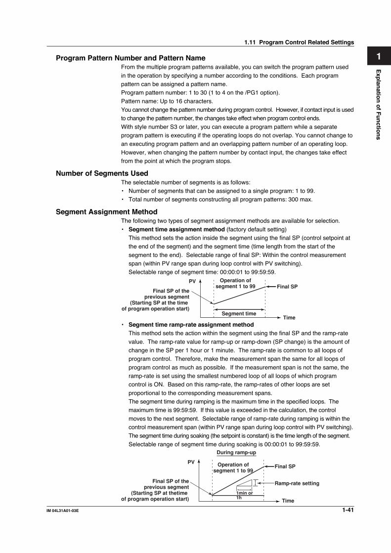
1-41IM 04L31A01-03E
Exp
lanatio
n o
f Fu
nctio
ns
3
2
1
4
5
6
7
8
9
10
11
12
13
14
Program Pattern Number and Pattern NameFrom the multiple program patterns available, you can switch the program pattern used
in the operation by specifying a number according to the conditions. Each programpattern can be assigned a pattern name.Program pattern number: 1 to 30 (1 to 4 on the /PG1 option).
Pattern name: Up to 16 characters.You cannot change the pattern number during program control. However, if contact input is usedto change the pattern number, the changes take effect when program control ends.
With style number S3 or later, you can execute a program pattern while a separateprogram pattern is executing if the operating loops do not overlap. You cannot change toan executing program pattern and an overlapping pattern number of an operating loop.
However, when changing the pattern number by contact input, the changes take effectfrom the point at which the program stops.
Number of Segments UsedThe selectable number of segments is as follows:• Number of segments that can be assigned to a single program: 1 to 99.• Total number of segments constructing all program patterns: 300 max.
Segment Assignment MethodThe following two types of segment assignment methods are available for selection.
• Segment time assignment method (factory default setting)This method sets the action inside the segment using the final SP (control setpoint atthe end of the segment) and the segment time (time length from the start of the
segment to the end). Selectable range of final SP: Within the control measurementspan (within PV range span during loop control with PV switching).Selectable range of segment time: 00:00:01 to 99:59:59.
Operation ofsegment 1 to 99 Final SP
Time
PV
Final SP of theprevious segment
(Starting SP at the time of program operation start)
Segment time
• Segment time ramp-rate assignment methodThis method sets the action within the segment using the final SP and the ramp-rate
value. The ramp-rate value for ramp-up or ramp-down (SP change) is the amount ofchange in the SP per 1 hour or 1 minute. The ramp-rate is common to all loops ofprogram control. Therefore, make the measurement span the same for all loops of
program control as much as possible. If the measurement span is not the same, theramp-rate is set using the smallest numbered loop of all loops of which programcontrol is ON. Based on this ramp-rate, the ramp-rates of other loops are set
proportional to the corresponding measurement spans.The segment time during ramping is the maximum time in the specified loops. Themaximum time is 99:59:59. If this value is exceeded in the calculation, the control
moves to the next segment. Selectable range of ramp-rate during ramping is within thecontrol measurement span (within PV range span during loop control with PV switching).The segment time during soaking (the setpoint is constant) is the time length of the segment.
Selectable range of segment time during soaking is 00:00:01 to 99:59:59.
PV Operation ofsegment 1 to 99
Time
Final SP
1min or1h
Final SP of theprevious segment
(Starting SP at thetime of program operation start)
Ramp-rate setting
During ramp-up
1.11 Program Control Related Settings

1-42 IM 04L31A01-03E
The segment assignment method applies to all segments constructing the programpattern. Note that the contents of program patterns created before are cleared when the
segment assignment method is changed.
Selecting the Start Condition for Program OperationThe following four operation start conditions (start codes) are available for selection.• Starting SP start (initial value).• Ramp-prioritized PV1 start
• Time-prioritized PV start• Ramp-prioritized PV2 startStarting Target Setpoint StartThe starting SP is the SP at the start of the program operation.When set to starting SP start, the SP is changed from the starting SP to the final SP. Inthis case, the change follows the ramp-rate defined by “(final SP – starting SP)/segment
time” regardless of the PV. When segment time ramp-rate assignment method isselected, the change follows the specified ramp-rate.
PV SEG1 SEG2TSPn: Final SPSSPn: Starting SP
Time
TSP2
SSP2
SSP1
TSP1Program pattern forthe 1st loop
Program pattern forthe 2nd loop
Segment time
Ramp-prioritized PV StartIn ramp-prioritized PV start, the program operation is started by specifying one of the
process values (PV1 or PV2) of loops 1 and 2. The patterns of other unspecifiedpatterns start according to the PV start pattern of the specified loop. The start pointvaries depending on the comparison between the starting PV of the specified loop and
the SP specified by the program pattern. The section of the program pattern that iscompared is from the starting SP to the first soak point or the first ramp-down start point(when the start segment is ramp-up). The start point is the point at which the starting PV
value and the setpoint on the program pattern match. If this matching point is not found,the start point is the end point of the program pattern being compared against.If the segment consists of only an up ramp and the starting PV is greater than the final SP, the
program control will not start and program control ends. In this case, SP tracking prcess is notperformed. If the start segment is a soak, this function does not operate, and the start conditionis the same as with the starting SP start.
Loops set to ramp-prioritized PV start that are in local or stopped mode and are no longer inprogram operation mode, change to starting SP start.Below are examples of ramp-prioritized PV1 start and ramp-prioritized PV2 start.
• Example in which the 2nd segment of the 1st loop is a soak segmentWhen set to ramp-prioritized PV1 start, the ramp-rate of the 1st loop is prioritized. Theprogram operation start point of the 1st loop will be point C1, D1, or E1 (depends on
the PV position a to e at that point). The program operation start point of the 2nd loop(one of the other loops) is at the same time as that of the 1st loop. For example, if theprogram operation start point of the 1st loop is point C1, the program operation start
point of the 2nd loop is point C2.
1.11 Program Control Related Settings

1-43IM 04L31A01-03E
Exp
lanatio
n o
f Fu
nctio
ns
3
2
1
4
5
6
7
8
9
10
11
12
13
14
PV
SEG1
A1
B1
D1
E1B2
C1
A2
C2
E2D2
SEG2 SEG3 SEG4 SEG5Time
a
b
cd
e
Program pattern forthe 2nd loop
Program pattern forthe 1st loop
• Example in which the 3rd segment of the 2nd loop is a soak segmentWhen set to ramp-prioritized PV2 start, the ramp-rate of the 2nd loop is prioritized.
The program operation start point of the 2nd loop will be one of the points from A2 toE2 (depends on the PV position a to e at that point). The program operation startpoint of the 1st loop (one of the other loops) is at the same time as that of the 2nd loop.
For example, if the program operation start point of the 2nd loop is point A2, theprogram operation start point of the 1st loop is point A1.
PV
SEG1
A1B1D1
E2
B2
C1
A2
C2
E1
D2
SEG2 SEG3 SEG4Time
Program pattern forthe 1st loop
Program pattern forthe 2nd loop
a
b
c
d
e
• Example in which the segment consists of only an up rampWhen set to ramp-prioritized PV1 start, the ramp-rate of the 1st loop is prioritized. Theprogram operation start point of the 1st loop will be one of the points from B1 to E1
(depends on the PV position a to e at that point. If the PV position is at point a,program operation will not start). The program operation start point of the 2nd loop(one of the other loops) must be at the same time as that of the 1st loop. For example,
if the program operation start point of the 1st loop is point B1, the program operationstart point of the 2nd loop is point B2.
PV
SEG1
A2B2
D2E1
B1
C2
A1
C1
E2
D1
SEG2Time
a
b
c
d
e
Program pattern forthe 1st loop
Program pattern forthe 2nd loop
1.11 Program Control Related Settings

1-44 IM 04L31A01-03E
Time-prioritized PV StartProgram operation is started by prioritizing the segment time to change the SP from the
PV at the start of program operation to the final SP of the 1st segment. The ten-segmentlinearizer ramp is defined by “(final SP – PV)/segment time.” When the 1st segment is asoak segment, the start condition is the same as with the starting target setpoint start.
• Example in which the 2nd segment is a soak segmentThe program operation start point of the 1st loop is always one of the points from point ato e. Since the program operation start point of the 2nd loop is at the same time as that
of the 1st loop, the program operation start point is one of the points point a2 to e2.PV
SEG1
TSP1
TSP2
TSPn: Final SP
C2
C1
SEG2 SEG3 SEG4 SEG5Time
C1
C1
C1
C1
Program pattern forthe 2nd loop
Program pattern forthe 1st loop
a
b
c
d
e
a2
b2
c2
d2
e2
NoteThis start method cannot be selected if the segment setting method is set to segment time
ramp grade.
Switching Conditions of Program Segments (program operation related setting)The operating conditions related to the switching of the segments can be specified for
each segment. Such conditions include the condition for switching to the next segmentand the operating conditions within the segment. The following four conditions forswitching the segment are available.
• Switching for continuation (initial value)• Hold-on switching• Local-mode end
• Reset-mode endSwitching for ContinuationWhen the segment set to switching for continuation ends, the next segment is executed.
When switching for continuation is specified on the last segment, the program operationis the same as when reset-end is specified. Below is an example of segment switchingfor continuation.
PV
TIMEn
SEG.n SEG.n + 1
Time
n = 1 to 98
TIMEn + 1
Final SP of segment n
When SEG.n ends, theoperation continuesto the next segment(SEG.n + 1).
1.11 Program Control Related Settings

1-45IM 04L31A01-03E
Exp
lanatio
n o
f Fu
nctio
ns
3
2
1
4
5
6
7
8
9
10
11
12
13
14
Hold-on SwitchingWhen a segment set to hold-on switching ends, the program operation is paused (hold
operation).The hold condition continues until the hold operation mode is cleared through keyoperation, external contact, or communication function. If the hold operation mode is
cleared at the last segment, the program operation is stopped (reset) and each controlloop enters the STOP status. In addition to releasing the hold mode, executing programRUN operation or executing advance during hold operation also clears the hold mode.
Below is an example of segment hold-on switching.PV
TIMEn
SEG.nSEG.n + 1
Time
n = 1 to 98
TIMEn + 1In hold
The hold mode continuesuntil it is cleared.
When the segment (SEG.n) to which holdswitching has been assigned ends, theprogram operation is paused (hold operation).
Local-Mode EndWhen the segment set to local-mode end is terminated, program control enters the stop(reset) status, and each control loop operates in the local mode (constant SP). The SPthat is used varies depending on the ON/OFF condition of target setpoint tracking as
follows. In addition, when the operation enters local mode, PV event and time event areturned OFF.• When the target setpoint tracking is ON
When the program operation of the last segment ends, the operation is set to localmode (constant SP) as shown below. At this point, the final SP of the last segment isused continuously as the SP in local mode. The “local SP” can be specified
beforehand. However, if the target setpoint tracking is ON, the PV tracks to the finalSP of the final segment regardless of the local SP.
PV
Time eventEVn
Last segmentSEG.n
Local SP
Time
n = 1 to 99
Programoperation
Localoperation
After the last segment ends, the localSP is set to the final SP of the last segment regardless of the "local SP" specified beforehand, and the operation continues under fixed-point control.
• When the target setpoint tracking is OFFWhen the program operation of the last segment ends, the operation is set to localmode (constant SP) as shown below (next page). At this point, the output is
controlled using the preset “local SP,” and PV event and time event are turned OFF.
1.11 Program Control Related Settings

1-46 IM 04L31A01-03E
PV
Time eventEVn
Last segmentSEG.n
Local SP
Time
n = 1 to 99
Programoperation
Localoperation
After the last segment ends,the operation continues underfixed-point control using the"local SP" specified beforehand.
Reset-Mode EndWhen the segment set to reset-mode end is terminated, program control enters the stop
(reset) status, and the operation of each control loop is stopped.Note
When creating the program pattern, data is created so that the segment set to [Local] or
[Reset] is the last segment of program control.
Wait OperationThis function is used to pause the program operation when the PV cannot track the SP.The program is paused to stop the change in the SP and waits for the PV to track theSP. When the PV tracks the SP, the program operation is automatically resumed.
This function has the following two types of operation.• Wait at the time of segment switching• Wait within the segment
The operation is set using the wait zone, which is the deviation width used to determinethe tracking level of the PV input, and the wait time, which is the time until the wait zoneis reached. Up to 5 groups of wait zone and wait time combination can be specified.
The wait operation applies to each loop. Therefore, if the PV of any loop does not reachthe wait zone, the operation switches from run mode to wait mode. Wait operation doesnot apply to loops that are in local mode or that are stopped. In cascade control, if the
primary loop is in local mode or if the secondary loop is stopped, wait operation does notapply. If in hold mode, wait operation is not performed because hold mode hasprecedence.
Wait at the Time of Segment SwitchingWait at the time of segment switching is the wait operation that is performed when thePV has not reached the final SP before changing to the next segment. If the PV reaches
the wait zone within the wait time, the operation moves to the next segment at that point.If the PV does not reach the wait zone within the wait time, the operation moves to thenext segment after the wait time elapses.
When the operation is switched to hold mode during wait operation, the wait time isreset. If the PV has not reached the wait zone when the hold mode is cleared, the timeris restarted from zero. If the remaining segment time is changed when in hold operation,
wait at the time of segment switching no longer applies, and the wait operation is reset.• Operation when the PV reaches the wait zone within the wait time
If the PV reaches the wait zone of the final SP before the wait time elapses after the wait
operation is started, the operation switches from wait mode to run mode and transits tothe next segment.
1.11 Program Control Related Settings

1-47IM 04L31A01-03E
Exp
lanatio
n o
f Fu
nctio
ns
3
2
1
4
5
6
7
8
9
10
11
12
13
14
SEG.n SEG.n + 1 n = 1 to 98
EVn EVn + 1
Wait zoneWait zone
Timerstopped
Wait time
PVTransits to the next segment(SEG.n + 1) when the wait zoneis reached.
Final SP
SP
• Operation when the PV does not reach the wait zone within the wait timeIf the wait time elapses before the PV reaches the wait zone, the operation switchesfrom wait mode to run mode at that point (even if the PV has not reached the final SP)
and transits to the next segment. However, if the wait time is set to 00:00:00, the waitoperation continues until the PV reaches the wait zone.
SEG.n SEG.n + 1 n = 1 to 98
EVn EVn + 1
Wait zoneWait zone
Timerstopped
Wait time
PV
The PV has not reached the wait zone, but the program transits to thenext segment when the waittime has elapsed.
Final SP
SP
NoteIf the wait time is changed during wait operation, wait operation continues using the new wait
time including the wait time that has already elapsed. If the new wait time is equal or shorter
than the wait time that has already elapsed, the wait operation ends at that point. If the wait
time is changed from 00:00:00 to some other value during wait operation, the wait operation
starts at that time using the new wait time.
Wait within the SegmentIf the PV falls outside the wait zone specified with respect to the current SP when theprogram operation is within the segment, the operation enters wait mode and theprogram operation is delayed. For wait operation within the segment, wait operation
continues until the PV reaches the wait zone regardless of the wait time setting. Whenthe PV returns within the wait zone, the operation switches from wait operation to runmode and the program operation is resumed. Wait operation is repeated every time the
PV falls out of the wait zone.Segment n
Wait period
PV
Wait zoneOriginal SP
SP
1.11 Program Control Related Settings

1-48 IM 04L31A01-03E
Event OutputThis function is used to output an alarm at a preset point in time or turn ON the contact
output after a given time elapses. The function operates in sync with the progression ofthe program operation. The event action operates at the start time of the segment towhich the event action is assigned. There are two types of event actions: time event and
PV event.• Number of time events/PV events that can be assigned to a single segment: 16 each.• Total number of events that can be assigned (total of all patterns): 800
You can set relay output (event output) corresponding to an event action. You can useone of the following types. However, only “event output for each program pattern” isavailable with versions of the CX earlier than 3.02.
• Common event output setting for all program patterns• Event output for each program patternTime EventTime event is a function used to turn ON the contact output after a specified time elapsesby starting the clock from the time the segment operation is started. The ON time andOFF time are specified in terms of the time elapsed from the start point of the specified
segment. You can specify a time exceeding the segment time of the specified segmentand event action.
SEG4SEG3SEG2
TSP2
TSP1
SEG1 SEG5
Time event 1
Time event 2
Time event 3
Program pattern forthe 2nd loop
Program pattern forthe 1st loop
TSPn: Final SP
ON time OFF time
ON time OFF time
ON time OFF time
Note• The event information of the time event is retained even after the segment to which the
time event is assigned.
• During the hold and wait operations, the time event count is temporarily stopped.
• With the ramp-prioritized PV start, if a pattern starts partway through a segment, the time
event also starts partway through.
1.11 Program Control Related Settings

1-49IM 04L31A01-03E
Exp
lanatio
n o
f Fu
nctio
ns
3
2
1
4
5
6
7
8
9
10
11
12
13
14
PV EventThis function outputs preset alarms such as PV alarms and deviation alarms during
program operation. PV events operate only within the specified segment.The following table shows the types of PV events. Hysteresis can be specified for each event.
Alarmsetpoint
Close
Hysteresis
Processvalue
Open
Close
Hysteresis
Open
Hysteresis
Open
SP
Deviationsetpoint
Close
Open
Hysteresis
Close
Relay action(Open/close: relay contact status)
Relay action(Open/close: relay contact status)Event type Event type
Hysteresis Hysteresis
Close Open Close
Hysteresis Hysteresis
OpenOpen
Close
Setpoint
Hysteresis
Hysteresis
Alarm setpoint Setpoint
Hysteresis
Output value
Hysteresis
Output value
PV high-limit
PV low-limit
Deviationhigh-imit
Deviationlow-limit
Deviationhigh & low
limit
PVAlarmsetpoint
Alarmsetpoint
Alarmsetpoint
Alarmsetpoint
Deviationsetpoint
Deviationsetpoint
Deviationsetpoint
Deviation within high & low limits
SP high-limit
SP low- limit
Output high-limit
Output low-limit
PV
SP
SP
SP
PV
PV
PV
Note• If the setup conditions of PV events are not specified using the same conditions also in the
next segment, they are reset at the time the operation of the specified program segment
ends.
• With cascade control, you can set PV events to the primary loop and secondary loop.
Switching the Program Pattern Using Contact InputsContact input is applied at [DI001-DI006] of the control output terminal block.
• Before version 3.02The program pattern is changed using contact inputs of binary representation.
• Version 3.20 and later
In addition to the binary representation, the program pattern can be changed usingcontact inputs of binary-coded decimal (BCD) representation. You can select Whetherto use [Binary] or [BCD]. The default setting is [Binary].
1.11 Program Control Related Settings

1-50 IM 04L31A01-03E
Repeat FunctionThis function repeats the operation over a section of the program pattern consisting of
continuous segments. To perform repeat operation, you specify the repeat startsegment, repeat end segment, and the number of repetitions (repeat count).Below is a program pattern in which the repeat count = 1, repeat start segment number = 3, and
repeat end segment number = 5. You can also specify an infinite number of repetitions.
TSP1
TSP2
SEG4 SEG6SEG5SEG3SEG5SEG4SEG3SEG2SEG1
Repeat period: repeat count = 1
Repeat startsegment number = 3
Repeat endsegment number = 5
TSPn: Final target setpoint
Program pattern forthe 2nd loop
Program pattern forthe 1st loop
Same value
Note• The operation when repeat action, repeat start segment, repeat end segment, and repeat
frequency (including infinity) are changed during program control is indicated below.
• When changed to repeat OFF or when the segment number at that point is larger than
the repeat end segment
Repeat action is not performed regardless of the repeat action performed (or not
performed) up to that point.
• When the segment number at that point is smaller than the repeat start segment
Repeat action is performed from the first repetition using the new settings regardless of
the repeat action performed (or not performed) up to that point.
• When the segment number at that point is between the repeat start segment and
repeat end segment
If the change is made before the repeat action is performed (including a change from
repeat OFF) or after the repeat action has been finished, repeat action is performed from
the first repetition using the new settings. If the change is made during repeat action, the
repeat action is performed the number of times specified by the new repeat frequency
including the number of repetitions that have been performed before the change. If the
new repeat frequency is smaller than or equal to the number of repetitions that have
been performed already before the change, the repeat action is terminated after the
current repetition. However, if the repeat frequency is changed from infinity to a finite
value, repeat action is started using the new repeat frequency from the change point.
• Only a single period of repeat action can be specified for each program pattern.
• Set the first SP of the repeat start segment the same as the last SP of the repeat end
segment. If they do not match, the start segment pattern will be affected.
• In repeat action, all time events that are ON are turned OFF when returning from repeat end
segment to repeat start segment. If “time-prioritized PV start” or “ramp-prioritized PV start” is
specified as a starting condition of the program operation, PV start is also performed when repeat
operation is started. However, PV start does not apply to loops in local mode or loops that are
stopped. In cascade control, PV start does not apply if the primary loop is in local mode or the
secondary loop is stopped. If PV start cannot be carried out, "starting target setpoint start" is
carried out.
1.11 Program Control Related Settings

1-51IM 04L31A01-03E
Exp
lanatio
n o
f Fu
nctio
ns
3
2
1
4
5
6
7
8
9
10
11
12
13
14
Program Operation Start DelayYou can set a delay (program start time) in starting the actual program pattern control
after carrying out the procedure for starting the program operation. The setting iscommon to all loops and is valid for a single program operation. The delay cannot bespecified during program control. The control output during program control is a preset
value. Hold and advance operations cannot be performed while delay is in effect.Selectable range of program start time: 00:00:00 to 99:59:59
PV
Time
Delay elapses
Program operation starts
SP
Delay
Program start operation
Specifying the Start Segment at the Time Program Operation Is StartedYou can specify the start segment number that is used at the time program operation isstarted. For example, this function can be used when you wish to set the programcurrently in operation back to the previous segment and restart the operation. Below is
an example in which the operation is started from segment 3.
SEG4SEG3SEG2SEG1 SEG5
TimeStart program operation from segment 3
B
C
A
Process value
Segment time of segment 3
When set toramp-prioritizedPV1 start
When set to time-prioritizedPV start
Current process value
When set to starting targetsetpoint start
SSP
TSP1 TSP2
TSP3 TSP4
TSP5
If the program operation is started from segment 3, the program operation startsaccording to the start conditions as follows.• When set to starting SP start
The program operates using point A as the starting SP and progresses towards point C.• When set to ramp-prioritized PV1 start
The program progresses from point B to point C.
• When set to time-prioritized PV startProgram operates from the current PV using the segment time of segment 3 andprogresses toward point C.
Hold OperationYou can hold the program progression (stop the timer) during program operation. You canhold the program using key operation on the program operation status display, using the
external contact input, or through the communication function. While the program operationis in hold mode, you can temporarily change the settings for the current segment. Whenhold mode is cleared, the operation continues with the new settings. Temporarily means
that the changes take effect in the operation of the current segment, but the setting itself isnot changed. The settings that can be changed temporarily are indicated below.• Change the final SP of the segment.
• Increase or decrease the remaining segment time.However, if the segment indicated in bold is a ramp segment and the segment time ramp settingmethod is used, you cannot change only the remaining segment time. If you change the final
SP, the remaining segment time changes accordingly.In addition to releasing the hold mode, executing program RUN operation or executingadvance during hold operation also clears the hold mode.
1.11 Program Control Related Settings

1-52 IM 04L31A01-03E
When changing the final SP of the segmentYou can change the SP during the hold operation. The ON/OFF time of the time event
and the segment time is adjusted by the amount of time the operation is held.
Hold period(Timer stopped)
Delay for the amount of timethe timer was stopped
Final SP
Time eventON
OFF
SEG1 SEG2 SEG3 SEG4 SEG5Pattern after the
setpoint is changed
Target SPchanged
Pattern before thesetpoint is changed
NoteWhen changing the final SP with the segment time ramp rate assignment method, thesegment time is also changed. The time event's event timer is not changed.
When increasing or decreasing the segment timeYou can increase or decrease the segment time during the hold operation.
If the segment time is increased or decreased during the hold operation, the ON/OFFtime and segment time is automatically adjusted by the amount of time the operation isheld and the amount of time the segment time is increased or decreased.
• Example in which the segment time is increased
SEG1 SEG2 SEG5SEG4SEG3
Remaining segmenttime increased
Final SP
ONOFF
Time event
Hold period(Timer stopped)
Delay for the amount of timethe timer was stopped
Pattern after theremainigsegment time isincreased
Pattern before the remainingsegment time is increased
• Example in which the segment time is decreased
SEG1 SEG2 SEG5SEG4SEG3
Final SP
ONOFF
Time event Hold period(Timer stopped)
The time event also decreases by the amountthe remaining segment time was decreased.
Delay for the amount of time the timer was stopped
Pattern after the remainingsegment time is decreased
Pattern before the remainingsegment time is decreased
Remaining segment timedecreased
1.11 Program Control Related Settings

1-53IM 04L31A01-03E
Exp
lanatio
n o
f Fu
nctio
ns
3
2
1
4
5
6
7
8
9
10
11
12
13
14
NoteWhen the remaining segment time is decreased and the event action timer times out, the time
event is forcibly generated at that point.
Example in which the final SP is changed using the segment time ramp gradesetup methodThe figure below shows the example in which both the final SP and the remainingsegment time are changed by changing the final SP using the segment time ramp gradesetup method.
TSP1
TSP3
TSP2
Previous TSP1
Previous TSP2
Previous TSP3
Segment n–1 Segment n+1Segment n
Remaining segment time
Change the final SP and remainingsegment time when in hold mode
Time event
TSP1 after changePrevious TSP1
Previous TSP2
Previous TSP3
Segment n–1 Segment n+1Segment n
Remaining segmenttime after change
Time event
TSP3 after change
TSP2 after change
TSP1 to 3: Target SP
On
Off
On
Off
Advancing SegmentsDuring program operation, you can force the program to advance to the next segment.
You can advance the program using key operation on the program operation statusdisplay, using the external contact input, or through the communication function.When you advance the program at the segment currently in operation, the program
advances to the next segment. However, depending on the segment at which thisfunction is executed, the following operation may take place.• When advance is executed at the last segment
The program operates according to the switching settings of the segment.When set to [Local]: The operation enters local modeWhen set to [Reset]: The operation enters reset mode (operation stop)
When set to [Continuous] or [Hold]: The operation enters reset mode (operation stop)• When advance is executed at the repeat end segment
Repeat operation is started.
• When advance is executed at a segment other than those described aboveThe program advances to the next segment regardless of the segment switching settings.
• When advance is executed when the program operation is on hold
The hold mode is cleared, and the program operates according to the segmentconditions described above.
Program pattern end signalWhen program control terminates normally (excluding forced termination), thetermination can be notified using contact output (also through communication function).The contact output is turn ON for 5 s after normal termination.
1.11 Program Control Related Settings

1-54 IM 04L31A01-03E
1.12 Tuning
Selecting Tuning ParametersUp to 21 tuning parameters can be shown on the tuning display. The parameters are
initially assigned as shown below. The name of the tuning parameters (such as SP) canbe changed using up to 6 characters. In addition to the tuning parameters below, [DR](control direction) and [H] (relay hysteresis) are available.
SP (target setpoint) D (derivative time) BS1 (measured value 1 input bias)*
A1 (alarm 1 setpoint) OH (High limit of the output limiter) FL1 (measured value 1 input filter)*
A2 (alarm 2 setpoint) OL (Low limit of the output limiter) BS2 (measured value 2 input bias)*
A3 (alarm 3 setpoint) MR (manual reset) FL2 (measured value 2 input filter)*
A4 (alarm 4 setpoint) PO (preset output) RT (ratio setting)*
P (proportional band) RBS (remote input bias)*
I (integral time) RFL (remote input filter)*
W01 to W36(control computation constant)*
* Applies to style number S3 or laterBS1, FL1, BS2, FL2, RFL, and W01-W36 cannot be selected when PV/SP computation is ON.
Manual Tuning OperationOn the tuning display as shown below, you can select the parameter you wish to tuneusing the arrow keys and change the value.
Auto Tuning the PID ConstantOn the tuning display, select the PID number you wish to auto-tune and execute auto tuning.

1-55IM 04L31A01-03E
Exp
lanatio
n o
f Fu
nctio
ns
3
2
1
4
5
6
7
8
9
10
11
12
13
14
Auto TuningAuto tuning is a function that automatically measures the process characteristics and
automatically sets the optimum PID constant. When auto tuning is executed, the controlouput is temporarily turned ON/OFF step-wise (see the following figure). From thehunting period and amplitude of the PV that is generated, the optimum PID constant is
calculated and set. This method is called the limit cycle method. Auto-tuning is allowedonly during auto operation under PID control. In addition, for cascade control, autotuning on the primary loop is possible only when cascade operation is in progress.
Setpoint
Processvalue
Controloutput
Auto tuning on PID control according tothe PID control determinedby auto tuning
Auto tuning endson the third hump.
Auto tuning in progress
OFF OFFON ONON
Time
Target Setpoint during Auto Tuning Execution (Auto Tuning Point)The auto tuning point can be limited in the range of 3 to 97% of the measurement span.Auto tuning points are indicated below.
• When Zone PID is selectedLocal operation
When specified group is in operation: SP specified by the SP number
When all groups are in operation: Midpoint of each reference pointProgram operation or remote operation
When specified group is in operation: SP when auto tuning is executed
When all groups are in operation: Midpoint of each reference point• When Zone PID is not selected
Local operation
SP specified by the SP numberProgram operation or remote operation
SP when auto tuning is executed
(However, the secondary loop of cascade control is the SP specified by the SPnumber)
NoteIf auto tuning is executed when any of the loops set to program control enabled (includes the
case when program control is enabled on the primary loop of cascade control) is in program
operation, the progress of the program operation is temporarily paused. The time event and
segment time are prolonged by the amount of time the program operation is paused. The
program operation is resumed when auto tuning on all loops set to program control enabled is
complete. When program operation is temporarily paused, hole operation, advance operation,
and PV event are valid. However, wait operation is invalid.
1.12 Tuning

1-56 IM 04L31A01-03E
1.13 Measurement Function Overview
Measurement InputDC voltage, thermocouple, resistance temperature detector, or ON/OFF signal (contact
signal or voltage signal) can be measured. The input signal is A/D-converted at a scaninterval of 1 s or 2 s and acquired to the internal memory. In addition, differencecomputation, square-root computation, and scaling can be carried out on the measured
data and acquired to the internal memory.
Displaying the Measured DataThe measured data acquired to the internal memory can be displayed on the operationdisplay using trend waveforms, numeric values (digital values), or bar graphs.Trend Display Digital Display
Bar Graph Display
Measurement AlarmsAlarms can be generated when the measured/computed data meets a certain condition.When an alarm occurs, you can have the information about the alarm displayed on theoperation display. Also, you can output relay signals from the alarm output terminal(ALARM) on the measurement alarm option terminal block, or the transistor outputterminal (DIGITAL OUT). You can also turn the internal switches ON.On the operation display, the alarm status is displayed as alarm icons in the statusdisplay section and using methods such as the trend, digital, bar graph, overview
displays. The detailed information about the alarms is displayed in the alarm summary.Alarm Indication Example on the Overview Display
Cursor
Area of channels on which analarm is occurring is indicatedin red
Area of channels on which an alarmis not occurring is indicated in greenMeasured/computed value
Channel No. or tag name
Alarm type
Alarm icon

1-57IM 04L31A01-03E
Exp
lanatio
n o
f Fu
nctio
ns
3
2
1
4
5
6
7
8
9
10
11
12
13
14
Alarm Summary Display ExampleNumber of the alarm information displayed on the bottom line
Number of the alarm information in the internal memory
Alarm occurrence channel (channel No. or tag)
Alarm No. (1, 2, 3, 4)/type (H, L, h, l, R, r, T, t)
Date and time when the alarm occurredDate and time when thealarm was released
Mark
Cursor
Saving DataThe measured data can also be saved to external storage media such as floppy disks(2HD), Zip disks (100 MB or 250 MB), and ATA flash memory cards (4 to 440 MB).
CX1000
1
2
3
4
DISP/ENTER
External storage medium(One of the following typesspecified at the time of purchase)
Floppy disk
Zip disk
ATA flashmemory card
The data that has been saved to an external storage medium can be displayed on a PCusing the DAQSTANDARD for CX software that comes with the package. The data can
also be loaded into the CX1000 to be displayed.
Communication FunctionBy using the Ethernet interface that comes standard with the CX1000, the data can betransferred to a server on a network (client function). The data stored on the CX1000’sexternal storage medium can also be read from a PC on the network (server function).
CX CXMeasured data
Server
Primary Secondary
Data on the externalstorage medium
PC
CX CX
The communication functions using the Ethernet or serial interface are not covered in thismanual. See the CX1000/CX2000 Communication Interface User’s Manual (IM 04L31A01-17E).
1.13 Measurement Function Overview

1-58 IM 04L31A01-03E
1.14 Measurement Function > Measurement InputRelated Settings
Integration Time of the A/D ConverterThe CX1000 uses an A/D converter to convert the sampled analog signal to a digitalsignal. At this point, the sampled data is integrated for a certain period to eliminate thenoise that is mixed in the input signal. You can select the integral time from [Auto]/
[50Hz(20ms)]/[60Hz(16.7ms)/100ms]. This setting applies not only to the measurementinput of the measurement function but also to the PV input of the control function. Bysetting the integration time of the A/D converter to match the time period corresponding
to one cycle of the power supply or an integer multiple of one cycle, the power supplyfrequency noise can be effectively eliminated. If [Auto] is selected, the recorder willautomatically detect the power supply frequency and select 16.7 ms or 20 ms. Because 100 ms
is an integer multiple of 16.7 ms and 20 ms, this setting can be used to eliminate the powerfrequency noise for either frequency, 50 Hz or 60 Hz.
Scan IntervalThe scan interval is the interval used to sample the input signal. You can select [1s] or[2s]. However, if the integral time is set to [100ms], the scan interval is fixed to 2 s.
NoteWhen performing four arithmetic operations on models with the computation function (/M1),
this scan interval is used to carry out the computation.
Input Type and Input Computation (Mode)There are six channels of measurement input channels (measurement channels). You canselect the type of signal input to each measurement channel from DC voltage, thermocouple,
resistance temperature detector, and ON/OFF input (contact signal or voltage signal). Inaddition, difference computation, square-root computation, and scaling can be performed on themeasured data and display or save the computed result as measured data.
On the CX1000, the input type and input computation type is set as a [Mode]. Inaddition, if [Mode] is set to difference computation, square-root computation, or scaling,the input type is set as a [Type].
Mode Notation in Setup* Description
DC voltage Voltage Measures a DC voltage in the range of ±20 mV to ±50 V.Thermocouple TC Measures temperatures corresponding to the temperature range of each
thermocouple type such as R, S, B, K, E, J, T, N, and W.Resistance RTD Measures temperatures corresponding to thetemperature detector appropriate range for Pt100 or JPt100.Scaling Scale The input signal can be scaled to a value in the appropriate unit and displayed. You
can select the input type from DC voltage, thermocouple, resistance temperaturedetector, and ON/OFF input.
Difference Delta Displays the value obtained by subtracting the measured value of another channel(called the reference channel) from the input signal of the specified channel as themeasured value for the specified channel. You can select the input type from DCvoltage, thermocouple, resistance temperature detector, and ON/OFF input.
ON/OFF input DI Displays the contact input or voltage input signals by correlating them to 0% or100% of the display range.Contact input: Closed contact is ON (1).
Open contact is OFF (0).Voltage input: Less than 2.4 V is OFF (0).
Greater than or equal to 2.4 V is ON (1)Square root Sqrt Calculates the square root of the input signal andcomputation displays the result as the measured value of the channel. The computed
result can also be scaled to a value in the appropriate unit and displayed.The input type is DC voltage only.
Skip Skip Disables the channel.
* Characters displayed as selections in the [Mode] box of the setting display. It is used when setting the measurement channels.

1-59IM 04L31A01-03E
Exp
lanatio
n o
f Fu
nctio
ns
3
2
1
4
5
6
7
8
9
10
11
12
13
14
Note• For current inputs, a shunt resistor is attached to the input terminal to convert the signal to
voltage input. The following table shows the available shunt resistors. For example, a
250-Ω shunt resistor is used to convert the signal to 1 to 5 V for 4-20 mA input.
Name Model Resistance
Shunt resistor 4159 20 250 Ω ± 0.1%
(for screw terminals) 4159 21 100 Ω ± 0.1%
4159 22 10 Ω ± 0.1%
• The square-root computation method of the CX1000 is indicated below.
F = (F - F )x max min V - Vx minmax minV - V
= minF
Meanings of the symbols are shown below.
Vmin: span lower limit, Vmax: span upper limit, Fmin: scale lower limit after conversion,
Fmax: scale upper limit after conversion, Vx: input voltage, Fx: scaling value.
If the value inside the root is negative, the computed result is displayed as follows.
When Fmin < Fmax: “–*****”
When Fmin > Fmax: “+*****”
Input Range and Measurable RangeWhen the input type is set to DC voltage, thermocouple, resistance temperature detector,
or ON/OFF input, you will select the range to match the input signal. For DC voltage, selectthe measurable range (select [20mV] for “–20.00 to 20.00 mV”). For thermocouple orresistance temperature detector, select the type. For example, the type selections for the
thermocouple are [R], [S], [B], [K], [E], [J], [T], [N], [W], [L], [U], [PLATINEL], [PR40-20], and[W3Re/W25Re]. If [R] is selected, the measurable range is 0.0 °C to 176.0 °C. In addition,you will set the measurement span ([Span lower limit] and [Span high limit]) within the
measurable range as the actual range for making measurements.
Burnout DetectionWhen measuring the temperature using a thermocouple, you can have the measurement resultset to positive overrange*1 or negative overrange*2 when a burnout occurs. Burnout can be seton each measurement channel. The initial setting is set so that burnout is not detected.*1 Positive overrange refers to the condition in which the input signal is exceeding the upper limit of
the measurable range of the input range. The measured value is show as “+*****”.
*2 Negative overrange refers to the condition in which the input signal is less than the lower limit of
the measurable range of the input range. The measured value is show as “–*****”.
Reference Junction CompensationWhen measuring the temperature using a thermocouple, the reference junction compensationcan be used. You can select whether to use the reference junction compensation provided by
the CX1000 or an external reference junction compensation. If you are using an externalreference junction compensation, you will also set the reference voltage. The initial setting is setso that the reference junction compensation provided by the CX1000 is used. When using the
external reference junction compensation, set an appropriate reference junctioncompensation voltage. As in the example in the following figure, if the reference junctiontemperature for the external reference junction compensation is T0 °C, set the
thermoelectromotive force of the 0-°C reference for T0 °C as the reference junctioncompensation voltage.
CX1000
External reference junction compensation(Hold the contact point of the thermocoupleand copper wire at T0 °C)
ThermocoupleCopper wire
1
2
3
4
DISP/ENTER
1.14 Measurement Function > Measurement Input Related Settings

1-60 IM 04L31A01-03E
Moving AverageThe moving average is used to suppress the effects of noise that is riding on the signal.
The input signal of the measurement channel is set to the averaged value of the m mostcurrent data points (the number of moving-averaged data points) acquired using the scaninterval. The number of moving-averaged data points (m) can be set in the range 2 to 16.
The figure below shows an example indicating the operation of the buffer for the movingaverage computation when the number of moving averaged data points is set to “5.”The moving average can be set on each channel. The moving average is initially turned
OFF.
1
2
3
4
5Cleared Cleared
Movingaverage
New data New data
Buffer data for the nthsampling time
Buffer data for the n+1thsampling time
Buffer data for the n+2thsampling time
10.0mV
5.0mV
0.0mV
–5.0mV
–10.0mV
0.0mV
15.0mV
10.0mV
5.0mV
0.0mV
–5.0mV
5.0mV
10.0mV
15.0mV
10.0mV
5.0mV
0.0mV
8.0mV
1.14 Measurement Function > Measurement Input Related Settings

1-61IM 04L31A01-03E
Exp
lanatio
n o
f Fu
nctio
ns
3
2
1
4
5
6
7
8
9
10
11
12
13
14
1.15 Measurement Function > Measurement AlarmRelated Settings
Turning ON/OFF the AlarmYou can set up to four alarms for each channel. You can set alarms not only onmeasurement channels but also computation channels. For each alarm, you can setdifferent alarm conditions.
Alarm ConditionsThe following eight conditions (shown as [Type] on the setting display) are available.
• Upper limit alarmAn alarm occurs when the measured/computed value exceeds the alarm value.
• Lower limit alarmAn alarm occurs when the measured/computed value falls below the alarm value.
Alarmvalue
Alarm release
Process value
Alarm occurrence
Upper limit alarm Lower limit alarm
Processvalue
Alarm release
AlarmvalueAlarm occurrence
• Difference upper limit alarm (can be set on difference computation channels only)
An alarm occurs when the difference in the measured values of two channels exceedsthe difference upper limit alarm value.
• Difference lower limit alarm (can be set on difference computation channels only)
An alarm occurs when the difference in the measured values of two channels fallsbelow the difference upper limit alarm value.
• Upper limit on rate-of-change alarm (can be set on measurement channels only)
The rate-of-change of the measured values is checked over a certain time (interval).An alarm occurs if the rate-of-change of the measured value in the rising directionexceeds the specified value.
• Lower limit on rate-of-change alarm (can be set on measurement channels only)The rate-of-change of the measured values is checked over a certain time (interval).An alarm occurs if the rate-of-change of the measured value in the falling direction
exceeds the specified value.
Measuredvalue
Change inthe measuredvalue
T1
Time
T2
Time
Upper limit on rate-of-change alarm Lower limit on rate-of-change alarm
Measuredvalue
Change inthe measuredvalue
Amount of changein the setting |T2-T1| T2
T1
Amount of changein the setting |T2-T1|
t2t1
Intervalt2-t1
Intervalt2-t1
t2 t1
The alarm value of the rate-of-change alarm is set using an absolute value. The intervalis derived using the following equation and set using the number of sampled data.Interval = Scan interval × number of sampled data
• Delay upper limit alarmAn alarm occurs when the measured/computed value remains above the alarm valuefor the specified time (delay).

1-62 IM 04L31A01-03E
• Delay lower limit alarmAn alarm occurs when the measured/computed value remains below the alarm value
for the specified time (delay).Delay upper limit alarm example (T is the specified delay)
Alarm releaseAlarm occurrence
T
X1 X2 X3 X4
T1
Measured value orcomputed value
Alarm setting
• Alarm does not occur at T1, because the time is shorter than the specified delay (T).• The input exceeds the alarm value at X2, but the alarm occurs at X3 at which the
specified delay period elapses (the time when the alarm occurs is the time at X3).
• The input falls below the alarm value at X4 and the alarm is released.
NoteThe following special operations are available for the delay upper/lower limit alarm.
• When a delay alarm is set on a computation channel and the computation is stopped
If the computation is stopped in a condition in which the computed value is exceeding the
alarm setting, the alarm is turned ON after the specified period (delay period) elapses.
Alarm occurrence
TComputedvalues
Stop computation
Alarm setting
• Delay alarm when a power failure occurs
Alarm detection is reset upon a power failure. It restarts the operation after the power recovers.
Power failureoccurrence/recovery
Power failureoccurrence/recovery
T T T
Alarm On Off On Off On Off
Measured value orcomputed value
Alarm setting
:Off
• Operation when the alarm setting is changed
• When a new delay alarm is set
The alarm detection starts at the time the alarm is set. It is unaffected by the conditions
existing before the alarm is set.
• If the alarm setting of a preexisting delay alarm is changed
• If an alarm is not occurring at the time of the change, alarm detection starts at the
new setting.
• If an alarm is occurring at the time of the change and the alarm type is set to delay
upper limit alarm, the alarm continues as long as the input is above or equal to the
new setting. If the input is below the new setting, the alarm turns OFF. If the alarm
type is set to delay lower limit alarm, the alarm continues as long as the input is
below or equal to the new setting. If the input is greater than the new setting, the
alarm turns OFF.
1.15 Measurement Function > Measurement Alarm Related Settings

1-63IM 04L31A01-03E
Exp
lanatio
n o
f Fu
nctio
ns
3
2
1
4
5
6
7
8
9
10
11
12
13
14
Alarm HysteresisYou can set a width (hysteresis) to the values used to activate and release alarms.
Alarm hysteresis prevents frequent activation and release of alarms when the measuredvalue is unstable around the alarm value. The hysteresis is fixed to 0.5% of themeasurement span (display scale width if the range is set to scale).
It is applied only on alarms set to upper/lower limit alarm on measurement channels, andthe function can be turned ON/OFF.Factory default setting: Hysteresis ON
Alarmsetting
Alarm releaseMeasured value
Alarm occurrence
Upper limit alarm Lower limit alarm
Measured valueAlarm release
Hysteresis (Approx. 0.5%)
Alarm occurrenceAlarmsetting
Alarm Relay OutputRelay Output ON/OFFA relay signal can be output from the alarm output terminal [ALARM] of themeasurement alarm option terminal block and the relay contact output/transistor outputterminal [DIGITAL OUT] of the control output terminal block. You can set whether to
output the relay signal for each alarm setting. You can also turn the internal switchesON (style number S3 or later).
Reflash AlarmThis function is used to notify alarms occurring after the relay is activated on the firstalarm when multiple alarms are assigned to a single alarm output relay. When this
function is turned ON, the output relay is temporarily (approx. 500 ms) released whenalarms after the first alarm occur. The initial setting is [Off] (not use reflash alarm).The reflash alarm function is set only on output relays I01, I02, and I03.
Alarm
Channel 1
Channel 3
Channel 2
Alarm output relay(Reflash alarm ON)
Alarm output relay(Reflash alarm OFF)
Approx.500 ms
Approx.500 ms
NoteIf the reflash alarm is set, I01 to I03 become dedicated reflash alarms regardless of the
number of alarm output relays. Therefore, relays I01 to I03 operate as OR logic (see “AND/
OR of Alarm Output Relays”) and non-hold (see “Hold/Non-hold Operation of Alarm Output
Relays”) regardless of the settings made in “AND/OR of alarm output relays” and “Hold/Non-
hold operation of the alarm output relay.”
1.15 Measurement Function > Measurement Alarm Related Settings

1-64 IM 04L31A01-03E
AND/OR of Alarm Output RelaysWhen a single alarm relay is shared among multiple alarms, you can select either
condition below to activate the alarm output relay.• AND: Activated when all assigned alarms are occurring simultaneously.• OR: Activated when any of the specified alarms is occurring.
Set the alarm output relays for taking the AND logic in the following fashion: “I01 (first relay)to Ixx (where xx is the relay number).” The value is initially set to [None] (no AND relay).
Alarm
Channel 1
AND
Channel 2
OR
Alarm output relay
NoteWhen the reflash alarm is turned ON, I01 to I03 operates as reflash alarms. They are fixed to
OR logic operation. Specifying AND produces no effect.
Energized/De-energized Operation of Alarm Output RelaysYou can select whether the alarm output relay is energized or de-energized when an
alarm occurs. If de-energized is selected, the alarm output relay behaves in the samefashion as when an alarm occurs if the power is shut down. The setting applies to allalarm outputs. The initial setting is [Energized].
NOEnergized
De-energized
C NC NO C NC NO C NC
NO C NC NO C NCNO C NC
When power isshut down
NO: Normally Opened, C: Common, NC: Normally Closed
When alarm isnot occurring
When alarm isoccurring
1.15 Measurement Function > Measurement Alarm Related Settings

1-65IM 04L31A01-03E
Exp
lanatio
n o
f Fu
nctio
ns
3
2
1
4
5
6
7
8
9
10
11
12
13
14
Hold/Non-hold Operation of Alarm Output RelaysYou can select the following behavior when the alarm switches from the activated
condition to the released condition (reverts to the normal condition).• Turn OFF the output relay with the release of the alarm (non-hold).• Hold the output relay at ON until an alarm ACK operation is performed (hold).
The setting applies to all alarm output relays. The initial setting is [Non-hold].
Alarm ON
When set to non-hold
When set to hold
Alarm OFF
Relay output ON*
Relay output OFF*
Alarm ACK
Alarm ON
Alarm OFF
Relay output ON*
Relay output OFF*
* Relay output ON/OFF is for the case whenNO (Normally Opened) terminal is used. If a NC (Normally Closed) terminal is used,the ON/OFF condition is reversed from thecondition shown in the left figure.
NoteWhen the reflash alarm is turned ON, I01 to I03 are set to non-hold. Specifying [Hold]
produces no effect.
Hold/Non-hold of Alarm IndicationsYou can select the following behavior when the alarm switches from the activated
condition to the released condition.• Clear the alarm indication with the release of the alarm (non-hold).• Hold the alarm indication until the alarm ACK operation is performed (hold).
The initial setting is [Non-hold].Alarm Icon Indication Example
Release
When indication is set to non-hold
Alarm
Occurrence
Red icon
Red icon
IndicationNone
When indication is set to hold
Occurrence
Release
None
Blinkingred icon Blinking
green icon
Alarm ACK
Blinkingred icon
Alarm ACK
Alarmicon
NoteThe non-hold/hold setting of the alarm indication also applies to control alarms.
Showing/Hiding the Alarm Display (Style Number S3 or Later)You can select whether or not to display alarms when they occur. When not displayingalarms, the alarm is output but not retained in the alarm summary.
1.15 Measurement Function > Measurement Alarm Related Settings

1-66 IM 04L31A01-03E
1.16 Display Function
Display Types and Switching OperationAs indicated in the following figure, key operation is used to switch the displays.
Power ONOperation mode
Common and measurement setting mode[Set mode]
Basic settingmode
MENU key
Menu
Operation display
Setup display(#1 to #11)
Setup display(#1 to #12**)
Menu
MENU key or ESC key
Soft keys MENU key orESC key
Soft keys ESC key
[End] soft key -> DISP/ENTER key(This operation saves the settings made in the basic setting mode.)
Control setting mode[Setting mode (Control)]
Setup display(#1 to #8)
Press the FUNCkey for 3 s
Soft keys MENU key orESC key
ESC key
MENU key
* #1 to #9 when program control is ON.
** #1 to #11: Basic common and measurement settings #12: Basic control settings
Press the FUNCkey for 3 sMenu
MenuThis display is used to select the necessary setup items.• Selection Display for Control Related Setup Items
Setting DisplayThis display is used to set various parameters for the selected item.• Control Input Range Setting Display

1-67IM 04L31A01-03E
Exp
lanatio
n o
f Fu
nctio
ns
3
2
1
4
5
6
7
8
9
10
11
12
13
14
Operation DisplayThis display is used to monitor the operation status and carry out control operations such
as running and stopping the operation.• Control Group Display (Controller Style) for Monitoring the Control Status and
Performing Control Operations
• Trend Display of Measured Data
Display ConstructionThe display consists of the operation status indication section, data display section, and
the soft key menu. However, on the measurement operation display, the [FUNC] keymust be pressed to show the soft key menu.[Control Group Display (Faceplate Style) Example]
Operation statusdisplay section
Control datadisplay section
Soft key menu
1.16 Display Function

1-68 IM 04L31A01-03E
• Operation Status Indication SectionThe following information is displayed in the status display section during operation
mode and setting mode. (The information is not displayed during basic setting mode.[Setup Mode] is displayed instead.)
1
85 9 11
103
4
72
6
A
B
C
E
F
G
H
When the internalmemory is partitionedinto 16 blocks
(When set to display data only)
(When set to [Free])
(When set to [Trigger] or [Rotate])
D
Data acquisition to theinternal memory in progress
Program control in progress1. User name
The user name is displayed when the key login function is used and the user is logged in.2. Group name or display name
The display name or group name corresponding to the display shown on the data display
section. [ALL] is displayed only when all channels are displayed on the trend display.3. Current date and time
The current date and time are displayed.
On models with the optional /BT1 batch header, the “date and time” and “batchnumber and lot number” are alternately displayed every 5 s when “Use BatchHeader” (see section 11.6) is being set.
4. Data acquisition to the internal memory ON/OFFA and B is alternately displayed: Data being acquired or waiting for a trigger for event data.C: Data acquisition stopped
D: When the control mode is set to a mode other than [Off] and the program controlis ON, program control RESET (red)/RUN (green) status is indicated in additionto the ON/OFF status of the data acquisition to the internal memory.
NoteFor event data that starts sampling when the trigger condition is met, the display indicates
that sampling is in progress even in the trigger wait state. The trigger wait state can be
determined on the bar graph.
5. Memory usage of the display data acquisition area in the internal memoryDisplayed when acquisition of display data is enabled.• Bar graph
Indicates the amount of display data acquisition area that is being used.• Time display
Remaining time of the display data acquisition area. When the remaining time
becomes short, the time is displayed in units of minutes.
Remaining time Unit
100 days or more % (Percentage of the remaining area in the display data acquisition area)100 hours or more to Days (time unit less then one day is truncated)less than 100 days60 minutes or more to Hours (time unit less then one hour is truncated)less than 100 hoursLess than 60 minutes Minutes (time unit less then one minute is truncated)
1.16 Display Function

1-69IM 04L31A01-03E
Exp
lanatio
n o
f Fu
nctio
ns
3
2
1
4
5
6
7
8
9
10
11
12
13
14
• n/16The maximum number of display data files that can be written to the internal
memory is 16. “16” represents this value.The value n is the number of display data files in the internal memory.
NoteIn the following cases, the display data is overwritten from the oldest file. Use caution
because the overwritten data is lost forever.
• When there is no more remaining time of the display data acquisition area in the internal
memory
At this point, the status display section shows [Overwrite].
• When the number of display data files in the internal memory has exceeded 16
6. Memory usage of the event data acquisition area in the internal memoryDisplayed when acquisition of event data is enabled.• When the acquisition mode is [Free]
• Bar graphIndicates the amount of event data acquisition area that is being used.
• Time display
Remaining time of the event data acquisition area. When the remaining timebecomes short, the time is displayed in units of minutes.
Remaining time Unit
100 days or more % (Percentage of the remaining area in the event data acquisition area)100 hours or more to Days (time unit less then one day is truncated)less than 100 days60 minutes or more to Hours (time unit less then one hour is truncated)less than 100 hoursLess than 60 minutes Minutes (time unit less then one minute is truncated)
• n/16
The maximum number of event data files that can be written to the internalmemory is 16. “16” represents this value.The value n is the number of event data files in the internal memory.
NoteIn the following cases, the event data is overwritten from the oldest file. Use caution because
the overwritten data is lost forever.
• When there is no more remaining time of the event data acquisition area in the internal memory
The status display section shows [Overwrite].
• When the number of event data files in the internal memory has exceeded 16
• When the mode is [Trigger] or [Rotate]• Bar graph
Displays the acquisition time (amount of memory used with respect to thedata length) of the specified event data.When pretrigger is specified and START is pressed causing the CX1000 to
enter the trigger wait state, data of size equal to the pretrigger amount isacquired to the internal memory. At this point the bar is displayed in orange.After acquiring the data of size equal to the pretrigger, the length of the bar
stays fixed. However, the relevant data is updated until the trigger conditionis met. When the trigger condition is met, the bar turns green. Data isacquired to the internal memory after the pretrigger data.
If data acquisition to all blocks is finished in [Trigger] mode, [Full] is displayedin the bar. When [Full] is displayed, event data is not acquired to the internalmemory even if the trigger condition is met.
1.16 Display Function

1-70 IM 04L31A01-03E
• Block displayWhen the event data acquisition area is divided into multiple blocks, the block
usage is displayed.White blocks: Blocks with no data.Green blocks: Block containing data that was acquired to the internal
memory after starting the current acquisition of event data.Gray blocks: Blocks containing previous data.
7. Icon indicating the external storage medium statusIf F and G are displayed alternately, the external storage medium is beingaccessed. If the icon is not displayed, this indicates that an external storagemedium is not inserted in the drive. Other indications are as follows.
E: The operation cover on the front panel is open.G: External storage medium waiting (not being accessed).H: The green level inside the icon indicates the amount of the external storage medium
used. If the remaining amount falls to 10% or less, the color changes to red.
Note• The CX1000 detects whether an external storage medium is inserted in the drive when the
operation cover is closed.
• To prevent adverse effects from dust, use the CX1000 with the door closed.
8. Computation icon (only on models with the computation option)No computation mark is displayed: No computation option or computation is stopped.White computation icon: Computation in progress.Yellow computation icon: Computation dropout occurred.
NoteComputation dropout occurs when the computation process cannot be completed within the
scan interval. Press “FUNC > [Math ACK] soft key” to set the icon back to a white
computation icon. If computation dropouts occur, increase the scan interval or reduce the
number of computation channels that are turned on.
9. Key lock iconKey icon: Key locked
No indication: No key lock
10. E-mail transmission function iconDisplayed when the e-mail transmission function (see the CX1000/CX2000Communication Interface User’s Manual) is enabled.
11. Alarm iconDisplayed when any one of the alarms is occurring.
• Data Display SectionThe control operation display shows the PV input values, SPs, and OUT for
monitoring the control status, tuning information, and so on. The measurementoperation display shows the trend display, digital display, and bar graph display of themeasured and computed data as well as alarm, message, and file information. For
details on the displayed contents, see the following pages.
1.16 Display Function

1-71IM 04L31A01-03E
Exp
lanatio
n o
f Fu
nctio
ns
3
2
1
4
5
6
7
8
9
10
11
12
13
14
Setting GroupsThe control monitoring data and measured/computed data on the operation display are
shown in groups. Therefore, control loops and measurement channels must beassigned to groups.Setting Control Groups (for the Control Function)Up to four loops by combining internal and external loops can be assigned to eachgroup. In addition to internal and external loops, measurement channels can also beassigned. You can assign up to four groups and assign a group name to each group for
easy identification.Setting Measurement Groups (for the Measurement Function)Measurement channels or computation channels are assigned. Up to six groups can be
registered. The groups are common to the trend, digital, and bar graph displays.On the trend, digital, and bar graph displays, the displayed groups can be automaticallyswitched at “5 s,” “10 s,” “20 s,” “30 s,” or “1 min” intervals.
For trend display, the waveform of all applicable channels can be displayed on a singledisplay rather than in groups.
Displaying TagsFor identifying the control loops and channels, tags (tag comments can also be assignedto control loops) can be displayed in place of numbers.
Control Operation Display > Control Group Display
Target setpoint (SP)Red: Can be setYellow: Cannot be set
Loop selectioncursor
Auto/manual
Tag name
PV input value*
Target setpoint*
Control output value*
Remote (REM) or local (LOC)Operation running (RUN), operation stopped (STP),or auto tuning (blinking AT)
Alarm mark
PV input valueUpper limit alarmRed: Alarm occurrenceGreen: Alarm OFF
Control output value (OUT)Red: ControllableYellow: Not controllable
Scale(The value indicates spanlower limit or upper limit.)
Process value (PV)Red: Alarm occurrenceGreen: Alarm OFF
Tag commentdisplay section
* Red when alarm is occurring
DIO operation monitoring function Analog retransmission
When monitoring only DI or DO
Displayed using the specified color when DO or DI is ON
Displayed using the specified color when DO or DI is OFF
Displayed using the specified color when DO is ON
Displayed using the specified color when DO is OFF
When monitoring both DI and DO
Displayed using the specified color when DI is ON
Displayed using the specified color when DI is OFF
Output value
Tag Tag comment
Label for ON
Label for OFF
1.16 Display Function

1-72 IM 04L31A01-03E
Control Operation Display > Tuning Display
Control parameter setupdisplay section
Control status indication section(similar to the display on thefaceplate control group display)
Trend waveform display of PV (green),SP (red), and OUT (yellow)
Setup displayAT: PID number being auto tunedSP No.: Current target setpoint numberPID No.: Current PID numberGroup No.: PID number of the tuning parameter to be manipulated
Time
PID numberItem name
Control Operation Display > Overview Display
Auto/manual
PV input valueTarget setpoint
Control output value
Tag name and tag comment
Remote (REM) or local (LOC)
Run (RUN)/Stop (STP)/auto tuning (blinking AT)
Red indicationwhen alarm isoccurring
Loop selection cursor
DIO operation monitoring function Analog retransmission
When monitoring only DI or DO
Displayed using the specified color when DO or DI is ON
Displayed using the specified color when DO or DI is OFF
Displayed using the specified color when DO is ON
Displayed using the specified color when DO is OFF
When monitoring both DI and DO
Displayed using the specified color when DI is ON
Displayed using the specified color when DI is OFF
Output value
TagTag comment
Label for ON
Label for OFF
1.16 Display Function

1-73IM 04L31A01-03E
Exp
lanatio
n o
f Fu
nctio
ns
3
2
1
4
5
6
7
8
9
10
11
12
13
14
Control Operation Display > DI/DO Status DisplayContact ON/OFF (red: ON, green: OFF)
Contact number (DI: input, DO: output) or label name (style 3 or later)
NoteContact displays with numbers “DOXXX” indicate the alarm output status, not the ON/OFF
status of the output. For example, if the energize/de-energize setting of an alarm output relay
is set to “de-energize,” the indication turns red when an alarm occurs to indicate that it is de-
energized.
Contorol Operation Display > Internal Switch Status Display (Style Number S3 or later)
Internal switch number
ON/OFF(red: ON, green: OFF)
1.16 Display Function

1-74 IM 04L31A01-03E
Control Operation Display > Control Action Summary Display
Operation status Date and time of occurrence
Number of control operation information in the internal memoryNumber of the control operation information displayed on the bottom line
Cursor(Select a control operation using the cursor and select [INFORMATION] > [JUMP TO HISTORY] from the display selection menu to display the historical trend of the data containing the selected control operation)
Tag name + tag comment or pattern name (when program operating)Pattern name while operation mode is RUN, RESET, HOLD ON/OFF, or WAIT ON/OFF
Note• The status indicates “****,” if an error is occurring on an external loop using the optional
Green series communication function.
• With style number S2 or earlier, the name is displayed as Tag name + tag comment or
program while the program is running.
Control Operation Display > Program Event Summary Display (Only on Models withthe Program Control Option)
Event ON/OFF status (red: ON, green: OFF)
Event ON timeEvent OFF time
Event kind
Number of the event information displayed on the bottom lineNumber of the event information in the internal memory
Cursor(Select an event using the cursor and select [INFORMATION] > [JUMP TO HISTORY] from the display selection menu to display the historical trend of the data containing the selected
Time event: TIME + 2-digit event number + pattern namePVE + 2-digit event number + tag name + event type or PVE + 2-digit event number + tag name
Note• For a description of the program control display and program selection display, see
section 6.4, "Operations on the Program Selection Display and Program Control Display."
• With style number S3 or later, you can select to display PV event types as PVE + 2-digit
event number + tag name + event type, or PVE + 2-digit event number + pattern name.
1.16 Display Function

1-75IM 04L31A01-03E
Exp
lanatio
n o
f Fu
nctio
ns
3
2
1
4
5
6
7
8
9
10
11
12
13
14
Control Operation Display > Trend DisplayDisplayed Information and Display DirectionIn addition to the waveforms of measured/computed data, PVs, SPs, and OUT ofinternal/external control loops are also assigned to channels and displayed. The displaydirection of the waveform can be set to horizontal or vertical as show in the following
figure. Numeric values can be displayed along with waveforms.Note
For a description of the assignment of internal control channels (internal loop channels) and external
control channels (external loop channels), see channel assignment explanation on page 1-86.
Trend (Vertical) Display
Measured or computed valueUnitAlarm mark
Message (message mark, time, and message)
Trip line
Scale
Display update rate
Numericaldisplay section(digital display section)
Channel No. or tag name
Trend (Vertical, All Channels) Display
Data of the selected group
Waveforms of all channels that areset to display the trend
Trend (Horizontal) DisplayType 1 Type 2
Displayed Info Description
Message Messages specified by the user can be displayed at arbitrary points in time. For example, by displaying amessage when a certain operation is carried out, the point at which the operation is carried out can be seenvisually. Displayed messages are saved.
Trip line You can display a line to indicate a particular value of interest (trip line) for each group. You can select the thicknessof the displayed line from three types: 1, 2, or 3 dots. Up to four trip lines can be displayed on a single group.
Scale A scale appropriate for the measured item can be displayed for each channel. The number of divisions of the displayscale created by the main scale marks can be set to a value in the range 4 to 12 divisions (also applies to the bargraph display). Medium and small scale marks are displayed in between the main scale marks. You can selectwhether or not to display the scale for each channel and the display position.
1.16 Display Function

1-76 IM 04L31A01-03E
Updating the Waveform and Updating the Numerical DisplayOne division on the CX1000 consists of 30 dots along the time axis on the LCD. The
displayed waveform is updated at an interval corresponding to one dot. This interval isdetermined by the time corresponding to one division (referred to as the display updaterate). The relationship between the display update rate and the speed of movement of
waveforms is as follows. Measured/computed values of the numerical display areupdated every second (every 2 s if the scan interval is set to 2 s on the).
Display Update Rate (/div) 1 min 2 min 5 min 10 min 20 min 30 min 1 h 2 h 4 h 10 h
Speed of Movement of 594 297 119 59 30 20 10 5 2.5 1.0Waveforms (approximate value, mm/h)
NoteThe speed of movement of the trend display along the time axis is derived from the following
equation given the dot pitch of the LCD (0.33 mm).
The speed of movement of the trend display along the time axis = 30 (dots) × 0.33 (mm) × 60
(min)/display update rate (min)
Display Format of WaveformsThe data shown on the display consists of maximum and minimum values of the data
that is sampled at the scan interval, within the time period corresponding to one dot.
1 minute
1 division (30 dots)
If the display update rate is set to 1 minute, the time correspondingto 1 dot (sampling interval of display data) is 2 s. For example,if the scan interval is 250 ms, the input signal is sampled 8 timeswithin a 2-s interval. The maximum and minimum values of the datasampled eight times are used as display data.
2 s (1 dot)
Maximum value
Minimum value
The time period corresponding to one dot is called “the sampling interval of displayeddata.” The sampling interval of displayed data is determined by the display updateinterval. The relationship between the display update rate and the sampling interval of
displayed data is as follows:
Display Update Rate (/div) 1 min 2 min 5 min 10 min 20 min 30 min 1 h 2 h 4 h 10 h
Sampling interval of 2 4 10 20 40 60 120 240 480 1200displayed data (s)
Zone DisplayThe waveform display range is called a zone. You can display channels by setting azone for each channel. Displaying the waveforms in separate zones facilitates reading
of the waveform. In the example in the figure, channel 1 is displayed in the 0 to 30%zone, channel 1 in the 30 to 60% zone, and channel 3 in the 60 to 100% zone.
Zone 2
Zone 1
Zone 3
100%
Time axis
30%
60%
100%
0%0%Time axis
When zone display is not used When zone display is used
CH3
CH2
CH1
1.16 Display Function

1-77IM 04L31A01-03E
Exp
lanatio
n o
f Fu
nctio
ns
3
2
1
4
5
6
7
8
9
10
11
12
13
14
Partial Expanded DisplayThis function compresses a section of the waveform display range and expands the rest
of the section. In this function, you specify the destination position (the new boundaryposition) where a single value (boundary point) in the display range is moved. In theexample in the figure, 0 V (boundary value) is moved to the 30% position of the display
range (new boundary position). The 30% below the boundary corresponds to “–6 V to 0V” and 70% above the boundary corresponds to “0 V to 6 V.”
100
Percentage withrespect to thedisplay span
Measuredvalue
BoundaryNewboundaryposition
100
300
500
6V
0–6V–6V 0
Exp
and
ed s
ecti
on
Reducedsection
Time axis Time axis
When partial expanded display is usedWhen partial expanded display is not used
Measuredvalue
6V
Percentage withrespect to thedisplay span
Waveform color and line thicknessThe waveform color can be set or changed for each channel. The waveform color andthe bar color in the bar graph display are the same.
You can select the thickness of the waveform line from 1 to 3 dots. The thickness of theline cannot be set separately for each channel.
Control Operation Display > Digital DisplayDisplays the measured, computed, and control data numerically using large numbers.
Unit
Channel No. or tag name
Measured or computed value
Specified alarm
Updating of the Numerical DisplayMeasured/computed values are updated every second (every 2 s if the scan interval is
set to 2 s).
1.16 Display Function
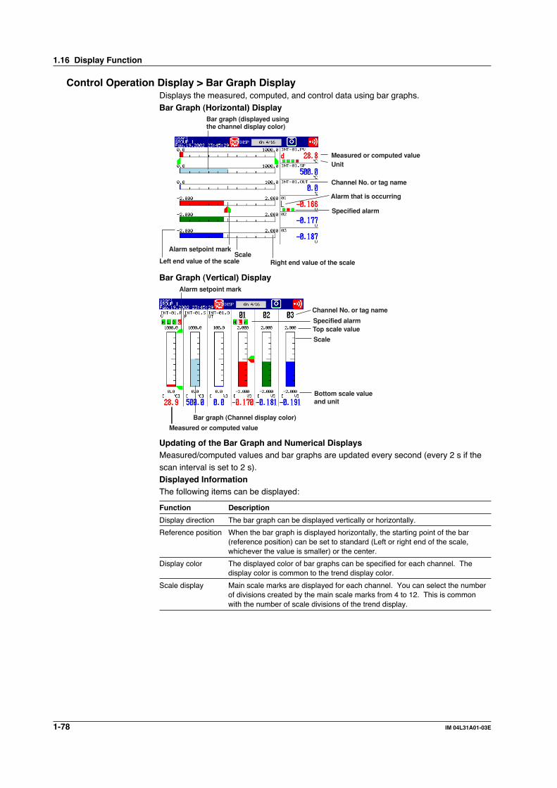
1-78 IM 04L31A01-03E
Control Operation Display > Bar Graph DisplayDisplays the measured, computed, and control data using bar graphs.
Bar Graph (Horizontal) Display
Unit
Alarm that is occurring
ScaleLeft end value of the scale Right end value of the scale
Specified alarm
Channel No. or tag name
Measured or computed value
Alarm setpoint mark
Bar graph (displayed usingthe channel display color)
Bar Graph (Vertical) Display
Specified alarm
Measured or computed value
Channel No. or tag name
Bar graph (Channel display color)
Bottom scale valueand unit
Scale
Top scale value
Alarm setpoint mark
Updating of the Bar Graph and Numerical DisplaysMeasured/computed values and bar graphs are updated every second (every 2 s if the
scan interval is set to 2 s).Displayed InformationThe following items can be displayed:
Function Description
Display direction The bar graph can be displayed vertically or horizontally.
Reference position When the bar graph is displayed horizontally, the starting point of the bar(reference position) can be set to standard (Left or right end of the scale,whichever the value is smaller) or the center.
Display color The displayed color of bar graphs can be specified for each channel. Thedisplay color is common to the trend display color.
Scale display Main scale marks are displayed for each channel. You can select the numberof divisions created by the main scale marks from 4 to 12. This is commonwith the number of scale divisions of the trend display.
1.16 Display Function

1-79IM 04L31A01-03E
Exp
lanatio
n o
f Fu
nctio
ns
3
2
1
4
5
6
7
8
9
10
11
12
13
14
Control Operation Display > Overview DisplayA list of measured/computed values and alarm conditions of all measurement/
computation channels is displayed. You can move the cursor to select a channel anddisplay the trend or bar graph of the group containing the selected channel. For theprocedure in displaying the overview display, see section 8.5.
Channel selection cursorMeasured or computed value
Channel No. or tag name
The type of alarm that is occurring
Area of channels on which an alarmis not occurring is indicated in green
Area of channels on which an alarmis occurring is indicated in red
Update Rate of the Numerical DisplayMeasured/computed values are updated every second (every 2 s if the scan interval isset to 2 s).
Control/Measurement Common Operation Display > Alarm SummaryLists the newest control alarms and measurement alarms. By scrolling the display using
the arrow keys, up to 120 incidents can be displayed. By selecting an alarm from the listusing up and down arrow keys, the historical trend of the display data or event datacontaining the alarm can be recalled. For a description on the historical trend display,
see the section “Measurement Operation Display > Historical Trend”.
Alarm selectioncursor*
Number of the alarm information displayed on the bottom line
Number of the alarm information in the internal memory (120 max.)
Control loop name (tag name + tag comment)/channel number (or tag name)Alarm number (1, 2, 3, 4)
Date and time whenthe alarm occurred
Date and time whenthe alarm was released
Alarm status indication mark
Alarm type (See page 4-24 for the meaning of control alarm symbols.See page 7-8 for the meaning of measurement alarm symbols.)
Control alarm: PVH, PVL, SPH, SPL, OTH, OTL, DVH, DVL, DVO, DVI, ETC (see Note below)Measurement alarm: H, L, h, l, R, r, T, t
* Select a alarm using the cursor and select [INFORMATION] > [JUMP TO HISTORY] on the display selection menu to display the data historical trend containing the selected alarm information.
Note• You can also display only the control alarms (see page 8-1).
• Alarm type indicates [ETC], if the alarm is an external loop and the alarm is of a type other
than the control alarms that you can specify on the CX1000.
1.16 Display Function

1-80 IM 04L31A01-03E
Control Operation Display > Message SummaryA list of written messages and the time the messages were written is displayed.
• Up to 120 sets of message information can be stored to the internal memory. Whenthe number of message information exceeds 120, the information is overwritten fromthe oldest information.
• By scrolling the screen using up and down arrow keys, the message information in theinternal memory can be displayed.
• By selecting a message from the list using up and down arrow keys, the historical
trend of the display data or event data containing the message can be recalled. For adescription on the historical trend display, see “Control Operation Display > HistoricalTrend” in this section.Number of the message displayed on the bottom line
Number of messages in the internal memory
Message string
Date/time when message as written
Name of the user who wrote the message(only when the key login function is used)
Cursor(Select a message using the cursor and select [INFORMATION] > [JUMP TO HISTORY]on the display selection menu to display the data historical trend containing theselected message.)
Control Operation Display > Memory SummaryThe information pertaining to the display data and event data in the internal memory is
displayed.• By selecting the display data or event data using the arrow keys, the historical trend
display can be recalled. For a description on the historical trend display, see “ControlOperation Display > Historical Trend” in this section.
• The number of manual sampled data, TLOG data (/M1 option), and report data (/M1option) residing in the internal memory are displayed.
• For models that have the alarm output relays (option), the ON/OFF status of therelays are also listed.
Number of data points in the internal memory/maximum numberof data points that can be acquired in the internal memory
Date/time when the newestdata was acquired
Date/time when the dataacquisition started
Date/time whenthe dataacquisitionended* Sampling count
Cursor(Select the data using the cursor and select [INFORMATION] > [JUMP TO HISTORY]on the display selection menu to display the historical trend of the selected data.)
Factor causing the end of dataacquisition
Data type (switch usinleft and right arrow keys)• Display data• Event data
* On models with the optional /BT1 batch header, the batch number and lot number for each file can be displayed in place of the date and time the data acquisition ended.
1.16 Display Function

1-81IM 04L31A01-03E
Exp
lanatio
n o
f Fu
nctio
ns
3
2
1
4
5
6
7
8
9
10
11
12
13
14
Control Operation Display > Report Data (Optional Function)Report data residing in the internal memory can be displayed.
The report function is used to write the average, minimum, maximum, and sum atspecified intervals for the specified channels. Reports can be made hourly, daily,weekly, or monthly.
Number of the report data being displayedNumber of report data in the internal memory
Type of report
Channel No. or tag name
Unit
Start date/time
Report data status
Report date/time
Average, maximum, minimum, and sum
Control Operation Display > Historical Trend DisplayThe waveform of the past display data* and event data* in the internal memory can bedisplayed. This function is called “Historical trend.”Methods of Displaying the Historical TrendThe following four methods are available in displaying the historical trend.• Display from the alarm summary.• Display from the message summary.
• Display from the memory summary.• Display from the control action summary.• Display from the program event summary (only on models with the program control
option)• Recall from the screen menu.Information Displayed on the Historical TrendAlarm information and scales are not displayed on the historical trend display.
Zoom factor of the time axis(using the display selection menu)
Time axis Channel No. or tag name
Measured/computed value(max. or min. value at the cursor position)
Measured/computed value(max. or min. value over the entire display range)
Waveform display(channel display color)
The background color isthe opposite of the trenddisplay color. (black or white)
Position of the newestdisplayed data
Date and time at the leftend on the time axis
Date and time at the rightend on the time axis
Screen switch displayUp arrow key:
Display the all data display(see the next page)
Down arrow key:Half screen display of currentand historical trend (see the next page)
Message
Trip line
Unit
This area is displayedusing the channeldisplay color.
1.16 Display Function

1-82 IM 04L31A01-03E
Operations on the Historical Trend Display• The waveform can be scrolled along the time axis using the left and right arrow keys
(for horizontal display) or up and down arrow keys (for vertical display).• The time axis can be expanded or reduced using the display selection menu ([TREND
HISTORY] > [ZOOM +] or [ZOOM -]).
• You can display all the data points on the historical trend display in a section of thescreen (all data display). When you move the cursor (yellow line) using the left andright arrow keys (for horizontal display), the date and time of the acquisition of the
data at the cursor position are displayed. By pressing the down arrow key (forhorizontal display) after moving the cursor to return to the original display, you canchange the display position within the entire data. In the display that appears, the
data at the cursor position is shown at the right end of the display.
All data displayCursor
Date and time at the cursor position
• You can display the information of the file displayed on the historical trend through thedisplay selection menu operation ([Historical Trend] > [Memory Information ON]).
Serial No. of the instrumentthat sampled the data
File name and data type
Start/end time and user name(User name is displayed only whenthe key login function is used.)
When batch header is active
Half Screen Display (Only When Displaying the Historical Trend of the Display Data)Using up and down arrow keys, you can have the left half of the display (lower half if thetrend display is vertical) show the historical data of the display data and the right half
(upper half if the trend display is vertical) show the display data currently beingmeasured.
Historical trend(Display data only) Current trend
Current trendinformation
1.16 Display Function

1-83IM 04L31A01-03E
Exp
lanatio
n o
f Fu
nctio
ns
3
2
1
4
5
6
7
8
9
10
11
12
13
14
Control Operation Display > Alarm DisplayThe measurement alarm status is indicated using an alarm icon on the status display
section (common with the control alarm) and the alarm indication on operation displayssuch as the trend display. The displayed pattern varies depending on the non-hold/holdmode of the alarm indication. In the explanation below, “Alarm ACK” refers to the alarm
release operation.Alarm Icon in the Status Display Section
Alarm icon
When indication isset to non-hold
AlarmOccurrence
Release
Alarm icon
When indication isset to hold
None Red None None None None NoneRed
Alarm ACK
Blinkingred
indication
Blinkinggreen
indication
Alarm ACK
Blinkingred
indication
Alarm Indication on the Trend Display
Measured value
Alarm mark
Alarm type
Mark for thespecified alarm
AlarmOccurrence
Release
Alarm ACK Alarm ACK
Blinkingred
indication
Blinkingred
indication
Blinkinggreen
indication RedGreen Red Green
When indication isset to non-hold
When indication isset to hold
Green Green Green Green
Alarm Indication on the Digital Display
Measured value
Alarm markWhen indication isset to non-hold
When indication isset to hold
Alarm ACK Alarm ACK
Mark for thespecified alarm
AlarmOccurrence
Release
Green Green Green Green Green GreenRedRed
Blinkingred
indication
Blinkingred
indication
Blinkinggreen
indication
1.16 Display Function

1-84 IM 04L31A01-03E
Alarm Indication on the Bar Graph Display
Alarm mark
Alarm setpoint mark
Measured value
Mark for thespecified alarm
AlarmOccurrence
Release
Alarm ACK Alarm ACK
When indication isset to non-hold
When indication isset to hold
Blinkingred
indication
Blinkingred
indication
Blinkinggreen
indicationGreen Green Green Green Green GreenRed Red
Alarm Indication on the Overview Display
Alarm type
Measured value Area of channels on which an alarmis occurring is indicated in red
Channel No. or tag name
Cursor
* When all the alarms occurring on the channel is acknowledged (alarm ACK).
Channel/Tag
Channel displayarea color
Alarm ACK* Alarm ACK*
When indication isset to non-hold
When indication isset to hold
AlarmOccurrence
Release
Green Green Green Green Green GreenRed Red Red
Blinkingindication
Blinkingindication
1.16 Display Function

1-85IM 04L31A01-03E
Exp
lanatio
n o
f Fu
nctio
ns
3
2
1
4
5
6
7
8
9
10
11
12
13
14
Alarm Summary DisplayA list of the most recent alarms can be displayed.
• Up to 120 sets of alarm information can be stored to the internal memory. When thenumber of alarm information exceeds 120, the information is overwritten from theoldest information.
• By scrolling the screen using arrow keys, the alarm information in the internal memorycan be displayed.
• You can select arbitrary alarm information and show the historical trend of the display
data or event data that contains the alarm information.For the operating procedure, see section 8.1.
* Select the alarm information using the cursor and select [INFORMATION] > [JUMP TO HISTORY]on the display selection menu to display the historical trend containing the selected alarminformation.)
Number of the alarm information displayed on the bottom line
Number of the alarm information in the internal memory (up to 120)
Alarm No. (1, 2, 3, 4)
Date/Time when thealarm occurred Date/Time when the alarm was released
Alarm type (See page 4-24 for the meaning of the control alarm symbols;see page 7-8 for the meaning of the measurement alarm symbols.)
Control loop name (tag + tag comment)/channel number (or tag)
Control alarms: PVH, PVL, SPH, SPL, OTH, OTL, DVH, DVL, DVO, DVI, ETC (see Note below)Measurement alarms: H, L, h, l, R, r, T, t
Alarm informationselection cursor*
Alarm status mark
Note• You can also display only the control alarms (see page 8-1).
• Alarm type indicates [ETC], if the alarm is an external loop and the alarm is of a type other
than the control alarms that you can specify on the CX1000.
Alarm Mark IndicationThe mark indication varies depending on the hold/non-hold setting of alarm indication
(see section 1.6) as follows.
Mark
Alarm ACK Alarm ACK
When indication isset to non-hold
When indication isset to hold
AlarmOccurrence
ReleaseBlinking
redindication
Blinkingred
indication
Blinkinggreen
indicationRed RedGreen Green Green
Setting the Display Conditions of the LCDThe following display conditions of the LCD can be configured.
Display Attribute Setting
Background color of The background color of the display can be set to white or black. The initialthe operation display setting of the control operation display is [Black]; the initial setting of the
measurement operation display is [White].
LCD brightness The brightness of the LCD can be set between eight levels. The initial setting is [4].
Backlight saver The lifetime of the LCD backlight can be extended by automatically dimmingthe light when there is no key operation for a certain amount of time. Thedisplay returns to the original brightness with a key operation or an alarmoccurrence. The initial setting is set so that the backlight saver is disabled.
1.16 Display Function

1-86 IM 04L31A01-03E
1.17 Data Storage Function
Data Acquisition to the Internal MemoryControl DataThe following control related data can be acquired to the internal memory. Controlrelated data includes the PV, SP, and OUT of external loops created through Greenseries communications (/CM1 optional function) in addition to those of internal loops.
Data Type Data Content
Display data Maximum/minimum values of PVs, SPs, and OUTs for every interval of acquisition to the internalmemory.
Event data Instantaneous value of PV, SP, and OUT at every specified sampling interval.
Manual sampled data Data in ASCII format containing the time and PV at the time of key operation or remote input.
Alarm summary data Channel on which alarm is occurred, alarm type, and time of occurrence and release.
Event summary data Loop number at which the time event or PV event occurred and the time of occurrence and release.
Operation mode Information of operation mode switching.summary data
Internal control channel (internal loop channel) assignments
The data of two loops is assigned to channel numbers as follows.
Loop 1 PV: 101, Loop 1 SP: 102, Loop 1 OUT: 103
Loop 2 PV: 104, Loop 6 SP: 105, Loop 6 OUT: 106
External control channel (external loop channel) assignments
The data of 4 loops is assigned to channel numbers as follows.
External loop 1 PV: 201, External loop 1 SP: 202, External loop 1 OUT: 203
•••
External loop 4 PV: 210, External loop 4 SP: 211, External loop 4 OUT: 212
Measurement Data• Display data and event data
The measured/computed/control data can be written to two types of data, display data
and event data, in the internal memory of the CX1000.Display dataData used to display waveforms on the CX1000 display. Display data consists of maximum
and minimum values of the measured or computed data sampled at the scan interval withinthe time period corresponding to one dot on the time axis on the display. The display datathat is saved can be likened to the conventional recording on the chart sheet and is useful for
observations of long-term changes. The data is saved in binary format.Event dataEvent data consists of instantaneous values of the measured/computed/control data at
specified sampling intervals. This is useful when you wish to observe the measured/computed/control data more in detail than display data. If the sampling interval is set tothe same value as the scan interval, all the measured or computed data sampled at the
scan interval can be acquired to the internal memory. The data is saved in binaryformat.
Measured/computed/control data per scaninterval
Display data
Event data
Sampling interval of dislay data (time equivalent to 1 dot on the display)
Scan intervalTime
Sampling interval of event data
Max. value per sampling intervalMin. value per sampling interval

1-87IM 04L31A01-03E
Exp
lanatio
n o
f Fu
nctio
ns
3
2
1
4
5
6
7
8
9
10
11
12
13
14
Internal memory sizeThe size of the internal memory for acquiring display data and event data is 1.2 MB. When
the measured/computed/control data is saved using both display data and event data, 0.9 MBand 0.3 MB of memory is used for display data and event data, respectively.
Display data Event data
0.9 MB0.3 MB
Display data
1.2 MB
Event data
When set to display data only When set to event data only When set to display data and event data
CX1000internalmemory
1
2
3
4
DISP/ENTER
1.2 MB
Data to be acquired and selecting the acquisition mode of event dataYou can select “display data only,” “display data and event data,” or “even data only”for the items to be acquired (“Data type” in the settings). If “display data and eventdata” or “event data only” is selected, you can select the acquisition mode (“Mode” in
the settings) from “Free,” “Trigger,” or “Rotate.” Refer to the following examples tomake the appropriate selection for your application.• Acquire only the display data at all times
Data to be acquired: Display data only• Acquire display data in normal cases and acquire event data around the alarm
occurrence when alarms occur
Data to be acquired: Display data and event data.Acquisition mode: Trigger or rotate
• Acquire event data at all times
Data to be acquired: Event data only. Acquisition mode: Free• Acquire event data only when alarms occur
Data to be acquired: Event data only. Acquisition mode: Trigger or rotate
Block segmentation during event data acquisitionIn the acquisition of event data, the acquisition area in the internal memory can bedivided into blocks (block segmentation). The acquisition operation varies depending
on whether the acquisition area is divided into blocks for each mode. For detailedinformation, see “Acquisition Mode of Event Data” in appendix 1, “SupplementaryExplanation of the Acquisition of Display Data/Event Data to the Internal Memory.”
You can select the number of blocks from 2, 4, 8, and 16.• Manual sampled data
Every time a given key operation is carried out, all measured/computed/control data
(instantaneous values) at that point is acquired to the internal memory except formeasurement channels that are skipped and computation channels that are turned OFF.
• TLOG data (only on models with the computation function option)
All the measured/computed data (instantaneous data) of all channels can be acquiredto the internal memory at the preset interval. However, this excludes measurementchannels that are skipped and computation channels that are turned OFF.
• Report data (only on models with the computation function option)The average, maximum, minimum, and sum can be computed for the specifiedchannels at the preset interval, and the result can be acquired to the internal memory.
You can select one hour (hourly report), one day (daily report), one hour/one day(hourly and daily), one day/one week (daily and weekly reports), or one day/onemonth (daily and monthly reports) for the interval.
1.17 Data Storage Function

1-88 IM 04L31A01-03E
Saving Data to the External Storage MediumThe data acquired to the internal memory can be saved to an external storage medium.
The following two methods are available in saving the data.Manual SaveThe data in the internal memory is saved to the external storage medium, only when the external
storage medium is inserted into the drive. You can specify whether to save the entire data in thememory or only the data that have not been saved to the external storage medium beforehand.Auto SaveHave the external storage medium inserted in the drive at all times. Data storage to theexternal storage medium is done automatically.
Note• If an external storage medium is not inserted when the data save operation is started
during “auto save” mode, the unsaved data is saved the first time the specified interval
elapses after an external storage medium is inserted.
• If the acquisition of the display data to the internal memory or acquisition of the event data
to the internal memory in free mode is started, you can save the display data or event data
at any time by operating the “[FUNC] key > soft key” even during auto save mode.
• Display dataThe display data in the internal memory is closed as a single file at the specified interval or atthe specified date and time and saved to the external storage medium in binary format.
7/19 13:10 7/20 13:10 7/21 13:10 7/22 13:10
Memory start Saved to the externalstorage medium
Examples of data save operation to the external storage mediumExample 1Auto save interval or data length: 1 dayDate and time when data is saved to the external storage medium: Not useAfter starting at 13:10, data is saved every day at 13:10 to the external storage medium.
7/19 13:10 7/20 0:00 7/21 0:00 7/22 0:00
Memory start Saved to the externalstorage medium
Example 2Auto save interval or data length: 1 dayDate and time when data is saved to the external storage medium: 0 hour every day.After starting at 13:10 on July 19th, data is saved at 0 hour on July 20th and then everyday after and at 0 hour every day (the same time for both in this example).
7/19 13:10 7/20 0:00 12:00 12:00 12:007/21 0:00 7/22 0:00
Example 3Auto save interval or data length: 12 hoursDate and time when data is saved to the external storage medium: 0 hour every day.After starting at 13:10 on July 19th, data is saved at 0 hour on July 20th and then every12 hours after and at 0 hour every day(0 hour occurs at the same time as the 12 hour timing).
Memory start Saved to the externalstorage medium
7/19 13:10 7/20 0:00 7/21 0:00 7/22 0:00
Memory start Saved to the externalstorage medium
Example 4Auto save interval or data length: 2 daysDate and time when data is saved to the external storage medium: 0 hour every day.After starting at 13:10 on July 19th, data is saved at 0 hour on July 20th and then every2 days after and at 0 hour every day (the 2-day timing occurs at the same time as 0 hour).
1.17 Data Storage Function

1-89IM 04L31A01-03E
Exp
lanatio
n o
f Fu
nctio
ns
3
2
1
4
5
6
7
8
9
10
11
12
13
14
• Event data• During the free mode
The event data in the internal memory is closed as a single file at the specifiedinterval (data length) or at the specified date and time and saved to the externalstorage medium in binary format.
• During trigger or rotate modeAfter acquiring the data to the internal memory over the specified period (datalength), the event data in the internal memory is stored to the external storage
medium in binary format.The following figure shows the operation when the acquisition area in the internalmemory is divided using the trigger mode.
Data acquisition
Trigger wait
Triggercondition met
Triggercondition met
Triggercondition metTrigger wait Trigger wait
Saved to the externalstorage medium
Saved to the externalstorage medium
Saved to the externalstorage medium
Stop
1st block 2nd block Last block
Data acquisition Data acquisition
• Manual sampled dataThe first time manual sample is executed, a manual sample data file is created on the
external storage medium. Data is added to this file every time manual sample isexecuted. The data is saved in ASCII format.
NoteIf an external storage medium is not inserted in the drive during auto save mode, the unsaved
data is saved the first time manual sample is executed after an external storage medium is
inserted.
• TLOG dataThe first time TLOG data is created, a TLOG data file is created on the externalstorage medium. The data is appended to this file at the specified interval. If the
number of TLOG data points saved exceed 400, a new file is created on the externalstorage medium. The data is saved in ASCII format.
• Report dataThe first time report data is created, a report data file is created on the externalstorage medium. A file is created for each type of report such as daily and monthly.The data is appended to this file every time of report.
The report file is divided at the following times. The data is saved in ASCII format.• For hourly reports• When the report at 0 hour every day is created.
• When the number of data points in a single file reaches 25.• For daily reports• When the report on the 1st day of every month is created.
• When the number of data points in a single file reaches 32.
Other Types of Data That Can Be StoredThe following two types of data can be stored on the external storage medium.
• Setup dataThe setup data can be saved to the external storage medium. The saved data can beloaded to change the CX1000 settings.
• Image data of the display screenThe image data of the display screen can be stored to the external storage medium inPNG format.
1.17 Data Storage Function

1-90 IM 04L31A01-03E
File Name• The file name “(Sampling month, day, hour, minute of the first data).extension” of
display data, event data, manual sample data, TLOG data, and report data isautomatically assigned.• Display data file: Mddhhmma.CDS
• Event data file: Mddhhmma.CEV• Manual sample data file: Mddhhmma.DMN• TLOG data file: Mddhhmma.DTG
• Hourly data file: Mddhhmma.DHR• Daily data file: Mddhhmma.DDR• Weekly data file: Mddhhmma.DWR
• Monthly data file: Mddhhmma.DMRM: Month (1-9, X (October), Y (November), Z (December), dd: day, hh: hour, mm: minute,a: the lowest digit of the year (0 to 9, except if another file with the same month, day,
hour, and minute exist, in which case “a” to “z” are assigned in order).• Setup data
Set the name using up to 8 characters through the save operation. A .pcl extension is
automatically added when the data is saved.• Screen image data
The file name “(month, day, hour, minute when the save operation of the screen
image data was executed+sequence number).png” is automatically assigned.Mddhhmma.PNGM: Month (1-9, X (October), Y (November), Z (December), dd: day, hh: hour, mm:
minute, a: the lowest digit of the year (0 to 9, except if the screen image data is savedmultiple times within a minute, in which case “a” to “z” are assigned in order from thesecond file)
Save Destination DirectoryAll the data excluding the setup data (display data, event data, manual sample data, TLOGdata, report data (only on models with the computation function option), and screen image
data) are saved to the specified directory. The setup data is saved to the root directory.The save destination directory varies depending on how the data is saved.Auto save: Directory specified here.
Manual save: Directory with a sequence number added to the stringspecified here.
Save on the setting display: Directory with “A+sequence number” added to the string
specified here (the sequence number increments every timethe data is saved).
File Header of Display Data and Event DataYou can enter a header comment using up to 32 alphanumeric characters.
Saving Data via the Ethernet NetworkThe display data, event data, and report data, as described in “Data Acquisition to the
Internal Memory,” can be automatically transferred to an FTP server via the Ethernetnetwork for storage. Conversely, the CX1000 can function as an FTP server. TheCX1000 can be accessed from a PC and the data in the external storage medium can be
retrieved for storage. For a description on these functions, see the CX1000/CX2000Communication Interface User’s Manual (IM 04L31A01-17E).
1.17 Data Storage Function

1-91IM 04L31A01-03E
Exp
lanatio
n o
f Fu
nctio
ns
3
2
1
4
5
6
7
8
9
10
11
12
13
14
1.18 Computation and Report Functions (Option)
Computation FunctionYou can perform computations by specifying a computing equation and display the results
as computed values of a computation channel, on various displays such as the trenddisplay, numerical display, and bar graph display. You can use data of measurementchannels, the data of computation channels, the data of control channels, constants, etc. in
the computing equation. Computed data can be saved similar to measured data ofmeasurement channels. Computation is performed every scan interval.Explanation of the computation function is also given in appendix 2, “Supplementary
Explanation of the Computation Function” and appendix 3, “Meaning and Syntax ofComputing Equations.” Read them along with this section.Channel Numbers Dedicated to ComputationsThe channel numbers dedicated to computations are 31 to 42 (12 channels).Computation Types and the Order of Precedence of ComputationsThe following computations can be performed. The order of precedence of computations
in descending order is functions (SQR, ABS, LOG, EXP, relational computation, logicalcomputation, and statistic computation), exponentiation, logical negation, multiplication/division, addition/subtraction, greater/less relation, equal/not equal relation, logical
product, logical sum/exclusive logical sum.
Type Description
Four arithmetic operation Addition (+), subtraction, multiplication (×), and division (/)
** Power. y = Xn
SQR Square root
ABS Absolute value
LOG Common logarithm
EXP Exponent. y = ex
Relational computation Determines <, ≤, >, ≥, =, or ≠ of two elements and outputs “0” or “1.”
Logical computation Determines the AND (logical product), OR (logical sum), XOR (exclusive logicalsum) of two elements, NOT (negation) of an element and outputs “0” or “1.”
Statistical computation Determines the average (AVE), maximum (MAX), minimum (MIN), sum(TLOG) (SUM), and maximum - minimum (P-P) at specified time intervals for the
specified channels.
Rolling average Determines the moving average of the computed results of the channels towhich a computing equation has been assigned. The sampling interval and thenumber of samples can be specified for each channel. The maximum samplinginterval is 1 hour; the maximum number of samples is 64.
Data That Can Be Used in Equations
Data Description
Measured data Measured value of a measurement channel or the control PV input.
Computed data Computed value of a computation channel.
Constants Set as constants K01 to K12 in the computation function.
Communication input data Values set using the communication function and written as C01 to C12(see the CX1000/CX2000 Communication Interface User’s Manual).
Conditions of the Remote Input signal (0 or 1) of the remote control function, written as D01 to D08.Control Terminals
Handing of the Unit in ComputationsThe unit corresponding to the measured/computed data in the equation is not
compensated. In computations, measured and computed data are handled as valueswithout units. For example, if the measured data from channel 01 is 20 mV and themeasured data from channel 02 is 20 V, the computed result of 01 + 02 is 40.

1-92 IM 04L31A01-03E
Displaying the Computed DataThe computed data that is assigned to computation channels can be displayed on
various operation displays using trend waveforms, bar graphs, and numerical values justlike measured data.Alarms of Computed DataLike measurement channels, up to four alarms can be assigned to each computation channel.Acquisition of Computed Data to the Internal MemoryLike measurement channels, the display data or event data of computation channels can
also be acquired to the internal memory and saved to an external storage medium. Inaddition, the instantaneous values and TLOG data of computation channels can besaved through manual sample operations.
Report FunctionThe report function is one of the functions of the computation function option (/M1). It isused to compute the average, maximum, minimum, and sum of each specified channel
at the specified interval and writing the result to the internal memory.Explanation of the report function is also given in appendix 4, “Additional Explanation ofthe Report Function.” Read it along with this section.
Item Description
Types of reports Select from hourly reports only, daily reports only, hourly and dailyreports, daily and weekly reports, and daily and monthly reports.
Number of channels per report Up to 12 channels
Computed data Average, maximum, minimum, and sum
Number of reports that can be Up to 40acquired to the internal memory
Data format ASCII format
The reports are created every hour on the hour for hourly reports, at the specified hour
for daily reports (once a day), at the specified hour on the specified day for weeklyreports (once a week), and at the specified hour on the hour on the specified date formonthly reports (once a week). For example, in the case of daily reports, the average,
maximum, minimum, and sum over a day for the specified channels are computed at thespecified time (on the hour), and the results are acquired to the internal memory. Thisconstitutes one report data set.
Unit of Sum ComputationIn the sum computation, data are summed over the scan interval. However, for flowvalues that have units /s, /min, /h, or /day a simple summation results in the actual value
not matching the computed result, because the scan interval and the unit of the inputvalues are different. In these cases, the unit of the data measured over the scan intervalis converted to match the unit of the input values, and the computation is performed.
For example, if the scan interval is 2 s, and the input value is 100 m3/min, a simplesummation would add 100 every 2 s resulting in 3000 after one minute. However, if thesum unit is set to /min, then 2 s/60 s is multiplied every scan interval before the value is
added giving a result that has an m3/min unit.The following converting equations are used to compute the sum. The scan interval unitis in seconds.
Off: Σ(measured/computed data every scan interval)/s: Σ(measured/computed data every scan interval) × scan interval/min: Σ(measured/computed data every scan interval) × scan interval/60
/h: Σ(measured/computed data every scan interval) × scan interval/3600/day: Σ(measured/computed data every scan interval) × scan interval/86400
1.18 Computation and Report Functions (Option)

1-93IM 04L31A01-03E
Exp
lanatio
n o
f Fu
nctio
ns
3
2
1
4
5
6
7
8
9
10
11
12
13
14
Operation during Power FailuresIf a power disruption occurred while the report function was in progress, the report
function will resume after the power is restored. The exact operation will vary dependingon whether the power is restored before or after the scheduled time to create a report.
Time of Recovery Port Operation
After the time to create the report Report data is created immediately after power is restored. Themeasured/computed data up to the time of the power disruption is used.For the next scheduled report, data after the power recovery are used.
Before the time to create the report After power is restored, report data are created at the time of the nextnormally scheduled report. The measured/computed data excludingthe power disruption period is used.
Handling of Abnormal DataHandling of the measured/computed data containing abnormal values is as follows.
Type of Abnormal Data Report DataAverage Value Maximum/Minimum Value Sum Value
Positive over* Not used Used Not usedNegative over* Not used Used Not usedError Not used Not used Not used
* “Over range” for measurement channels or “computation overflow” for computation channels.
StatusIf the data of a measurement or a computation channel enters any of the conditionslisted below within the relevant time period (one hour for hourly reports and one day for
daily reports, for example), status is output to the report.
Data Condition Status
Common to measurement and computation channelsMeasurement error or computation error E
For measurement channelsPositive (+) over range ONegative (–) over range OWhen the input type is voltage, over range occurs when the measured value exceeds themeasurable range of ±5%.Suppose the measurement range is 2 V, and the measurable range is –2.000 to 2.000 V. If themeasured value exceeds 2.200 V, positive over range results; if the measured value falls below –2.200 V, negative over range results.If the input type is TC (thermocouple) or RTD (resistance temperature detector), over range occurs when themeasured value exceeds approximately ±10°C of the measurable range. Suppose the measurement rangeis R, and the measurable range is 0.0 to 1760.0 °C. If the measured value exceeds 1770.0 °C, positive overrange results; if the measured value falls below –10.0 °C, negative over range results.
For computation channelsPositive (+) computation overflow (when the value exceeds 3.4E + 38) ONegative (–) computation overflow (when the value falls below –3.4E + 38) O
Power failure/Time change Status
When a power failure occurs P
When the time is changed C
1.18 Computation and Report Functions (Option)

1-94 IM 04L31A01-03E
Numerical DisplayThe range of displayed values of report data is from –9999999 to 99999999 excluding
the decimal point. The decimal point position corresponds to the position of the decimalpoint of the upper and lower limit span or upper and lower limit scale (for scaling).However, special displays are used for cases given in the table below.
• Measurement channel
Item Data Condition of Measurement Channels Displayed Output
Average value When all of the data are measurement errors or over range (Blank)
Maximum/Minimum Value • When all of the data are measurement errors (Blank)• Positive (+) over range 99999• Negative (-) over range –99999
Sum • When all of the data are measurement errors or (Blank)over range
• When the sum value exceeds 3.4E + 38 9.999999E+99• When the sum value is below –3.4E + 38 –9.999999E+99
• Computation channel
Item Data Condition of Computation Channels Displayed Output
Average value When all of the data are computation errors or (Blank)computation overflow
Maximum/Minimum value • When all of the data are computation errors (Blank)• When the maximum value exceeds 99999999 999999999• When the minimum value is –9999999 –99999999The decimal position that was specified when the span for the channelwas specified applies to the maximum and minimum values. Forexample, if the span setting of the channel is “200.0,” then “99999999” isoutput when the value exceeds “99999999.9” and “–99999999” is outputwhen the value is below “–999999.9.”
Sum • When all of the data are computation errors or (Blank)computation overflow
• When the sum value exceeds 3.4E + 38 9.999999E+99• When the sum value is below –3.4E + 38 –9.999999E+99
Displaying and Saving Report DataThe report data in the internal memory can be displayed on the LCD of the CX1000. Inaddition, the report data in the internal memory can be saved to an external storagemedium. The figure below shows an example of an hourly report.
Number of the report data being displayedNumber of report data in the internal memory
Type of report
Channel No. or tag name
Unit
Start date/time
Report data status
Date/time of the report
Average, maximum, minimum, and sum
1.18 Computation and Report Functions (Option)

1-95IM 04L31A01-03E
Exp
lanatio
n o
f Fu
nctio
ns
3
2
1
4
5
6
7
8
9
10
11
12
13
14
1.19 Equations for Control Computation (StyleNumber S3 or Later)
PV/SP ComputationWhen PV and program control function is OFF, you can set an equation for SP of theloops set to remote SP.Computation Type• Measurement computations other than TLOG computations• CLOG
You can calculate the max value, min value, average, and the difference in the max
and min values of data measured at the same time (max 10 channels). Measurementdata and control input data can be used for this computation.You can not set an equation inside the CLOG equation.
One CLOG only can be set within the PV/SP equation.The target data designation is delimited with periods. You can use hyphens toexpress a continuous range of channels.
• ConditionsA different computation is performed depending on the computed results of thespecified equation.
For [eq1?eq2:eq3], if the computed result of eq1 is other than 0, eq2 is computed, andif that result is 0, then eq3 is computed.You can set a conditional expressions such as [eq1?[eq2-1?eq2-2:eq2-3]:[eq3-1?eq3-
2:eq3-3]].Equations may not be used simultaneously.
Data That Can Be Used in EquationsThe data that can be used in equations is the same data that can be used for themeasurement computation function, plus the following:• Control input channel data (2 loop models: CI01-CI05).
• Constants (however W01-W12, and the measurement constants K01-K12 cannot beused).
• Status of internal switches.
• The status of the control relays (DO001-DO006).
Logic ComputationThe computed result is output to the DO or internal switch as a 0 or 1.Computation Type
Computation Type Operator
Logical operation AND, OR, XOR, NOT
Relational operation .GT., .LT., .GE., .LE., .EQ., .NE.
Conditional expressions [eq1?eq2: eq3]
Data That Can Be Used in EquationsSame as for PV/SP computation.
Analog RetransmissionIf the control mode is Analog Retransmission, you can set an equation for the controloutput.
The data that can be used for the equation and the computation is the same as for thePV/SP computation.

1-96 IM 04L31A01-03E
1.20 Other Functions
USER KeyOne of the following actions can be assigned to the USER key. The key is initially
assigned “Alarm ACK.”Actions That Can Be Assigned
Name of Action Action
Trigger Key trigger used to start acquiring event data to the internal memory (valid onlywhen event data is specified to be acquired to the internal memory and thetrigger used to start the acquisition is set to key trigger).
Alarm ACK Clears alarm display/relay output (valid only when the operation of the alarmdisplay or output relay is set to “hold”).
Math Starts/stops computation (only on models with the computation function (/M1)).Math reset Resets computed data (Resets the computed value to 0. Only when
computation is stopped on models with the computation function option).Manual sample Acquires instantaneous values of all channels to the internal memory.Messages 1 to 8 Displays message 1 to 8 on the trend display and stores the message to the
internal memory.Snapshot Saves the screen image data to the external storage medium.
Key LockKey lock is a function used to prohibit key operations, removal of the Zip disk, and savingof the data to the external storage medium in manual save mode, soft key operations on
the control operation display, and setup operation on the control setting display. Youmust enter a password to release the key lock.Key Lock ItemThe characters in the middle column are the characters of the soft key menu that aredisplayed on the control operation screen.
Operation during Key LockAll keys except those shown in the following table are disabled.
Key Lock Item Operation When Key Lock Is Enabled
DISP/ENTER key Switching of operation displays prohibitedExternal storage medium• During manual save mode Saving of data when the external storage medium is inserted is
prohibited. Zip disk removal prohibited on models with Zip drives.• During auto save mode Zip disk removal prohibited on models with Zip drives.Control menu lock Soft keys that are locked cannot be used on setting mode (control)
menu.

1-97IM 04L31A01-03E
Exp
lanatio
n o
f Fu
nctio
ns
3
2
1
4
5
6
7
8
9
10
11
12
13
14
Key Login/LogoutYou can set the CX1000 so that only certain users can operate the instrument. User name,
user ID, and password are used to identify a user. Up to 7 users can be registered.
Log DisplayA list of phenomena that occurred can be displayed in the order of occurrence for the
following types. The newest 200 incidents are stored for communication commands; thenewest 50 incidents are stored for other items.Error Message Log
Date/time when the error occurred
Error code Error message
Key Login/Logout Log
Date/time of key login/logoutIn: Key login, Out: Logout
User name
Number of the log displayed on the bottomline/total number of logs
Communication Command Log
Date/time the CX1000 was accessed
Number identifying the connected user
Input/output signal(>: input, <: output)
Message (up to 20 characters)
Number of the log displayed onthe bottom line/total number of logs
Connection status indication of theEthernet interfaceIlluminated (green): Connected electricallyNot illuminated: Not connected electrically
File Transfer Log Using the FTP Client Function
Date/time when file was transferred
Error code
FTP connection destination (P: primary, S: secondary)
File name (8 characters)
Number of the log displayed on the bottom line/total number of logs
Web Operation Log
Date/time when the operation was carried out on the Web screen.
Operation informationError code (See chapter 12.)
Operation type
1.20 Other Functions

1-98 IM 04L31A01-03E
E-mail Transmission LogNumber of measurement inputs (measurement channels)
Number of computation channelsNumber of internal control loops
Internal memory sizeCommunication interfaceExternal storage medium
MAC address Firmware version
Program controlGreen series communicationsLadder communications
Type of terminal block 1(PID: Exists, Alarm: Measurement alarmoption, NONE: None)
System DisplayThe total number of inputs on the CX1000, the size of the internal memory, thecommunication functions, the external storage drive, the options, and the MAC address,and the firmware version number can be displayed.
Number of measurement inputs (measurement channels)Number of computation channels
Number of internal control loops
Internal memory sizeCommunication interfaceExternal storage medium
MAC address Firmware version
Program controlGreen series communicationsLadder communications
Type of terminal block 1(PID: Exists, Alarm: Measurement alarmoption, NONE: None)
Displayed LanguageThe displayed language can be set to English, Japanese, German, French or Chinese*.
* Can be selected on a CX of version 3.02 or later.
1.20 Other Functions

1-99IM 04L31A01-03E
Exp
lanatio
n o
f Fu
nctio
ns
3
2
1
4
5
6
7
8
9
10
11
12
13
14
FAIL/Memory End Relay Output (/A4F option or /A4FR option)FAIL OutputWhen a failure occurs in the CPU of the CX1000, a relay contact signal (1 signal) isoutput.The relay is energized when the CPU is normal; it is de-energized when a CPU failure
occurs (de-energized on failure). Therefore, relay output is carried out also when thepower is turned OFF (including a power failure) (see figure below). You cannot changethis behavior.
The following figure shows the operation of the FAIL output relay (de-energized type).
NO C NC
During normal operation
NO C NC
When a failure occurs
NO C NC
When power is turned OFF
* NO, C, and NC are names of the relay output terminals.
NO: Normally Opened, C: Common, NC: Normally Closed
Memory End OutputWhen the remaining free space in the internal memory or external storage mediumbecomes small, a relay contact signal (1 signal) is output. When a memory end isdetected, the relay is energized (energized on memory end). You cannot change this so
that it is de-energized on memory end. When memory end is output, save the data to anexternal storage medium (during manual save mode) or change the external storagemedium (during auto save mode).
The memory end output operates as follows:• During auto save mode
If an external storage medium is inserted in auto save mode, the relay is energized
when the remaining free space on the external storage medium falls to 10%. (At thispoint, the icon indicating the status of the external storage medium in the statusdisplay section turns from green to red.)
• During manual save mode• If the type of data to be saved is display data only or display data and event data,
the relay is energized when the remaining amount of time for acquiring the display
data in the internal memory falls to the specified time.• If the type of data to be saved is event data only
If the CX1000 is in a mode in which data acquisition to the internal memory starts
at the same time as the start of measurement, the relay is energized when theremaining amount of time for acquiring the event data falls to the specified time.If the CX1000 is in a mode in which the data acquisition to the internal memory is
started using a trigger such as an alarm occurrence, the relay is not energized (nomemory end output).
The following figure shows the operation of the memory end output relay (energized on
memory end).
NO C NC
During normal operation
NO C NC
When memory end occurs
NO C NC
When power is turned OFF
1.20 Other Functions

1-100 IM 04L31A01-03E
Measurement Remote Input (/A6R option or /A4FR option)The actions shown in the table can be assigned to the contact signal or open collector
signal that is input to the 8 remote input terminals [REMOTE] of the measurement alarmoption terminal block.
Name of Action Detection Method Action
Start/Stop Edge Starts/stops data acquisition to the internal memoryTrigger Trigger Trigger used to start acquiring event data to the internal
memory (valid only when “event data” is specified to beacquired to the internal memory and the trigger used tostart the acquisition is set to “external trigger”).
Alarm ACK Trigger Clears alarm display/relay output (valid only when theoperation of the alarm display or output relay is set to“hold”).
Time adj Trigger Adjusts the internal clock to the nearest hour.Math Edge Starts/stops computation (only on models with the
computation function (/M1)).Math reset Trigger Resets computed data of measurement channels
(Resets the computed value to 0. Only whencomputation is stopped on models with the computationfunction option).
Manual sample Trigger Acquires instantaneous values of all channels to theinternal memory.
Load setup data 1 to 3 Trigger Loads the setup data file saved to the external storagemedium.
Messages 1 to 8 Trigger Displays message 1 to 8 on the trend display and storesthe message to the internal memory.
Snapshot Trigger Saves the screen image data to the external storagemedium.
Note• The actions above can also be registered to the contact inputs of the control output terminal
block.
• If the same action is performed using keys of the CX1000, communications, and contact
input, the newest operation/input is valid regardless of the method. This is also true between
control contact inputs and measurement remote inputs.
Method of Detecting the Remote Input SignalThe above actions are carried out on the rising or falling edge of the remote input signal
(edge) or the ON signal lasting at least 250 ms (trigger). For contact inputs, the remotesignal rises when the contact switches from “open to closed” and falls when the contactswitches from “closed to open”. For open collector signals, the remote signal rises when
the collector signal (voltage level of the remote terminal) goes from “high to low” and fallswhen the collector signal goes “low to high.”
Rising and falling edges Trigger
Rising Falling 250 ms or more
1.20 Other Functions

1-101IM 04L31A01-03E
Exp
lanatio
n o
f Fu
nctio
ns
3
2
1
4
5
6
7
8
9
10
11
12
13
14
Batch Header (/BT1 Option)Batch header is used to include information such as batch numbers and lot numbers
along with the data acquired to the internal memory. By including information such asbatch numbers, lot numbers, and supervisor names along with the measured/control/computed data, you will be able to manage the stored data. By using the key login
function in combination with this function, the operators that are allowed to store data onthe CX can be restricted and identified.
Adding Batch Information to the Measured/Control/Computed Data(Display Data and Event Data)The following information can be added to the display data and event data acquired to
the internal memory. For the setting procedure, see section 11.7.The operator can change the batch number, lot number, and comment for each lot. Inaddition, the lot number can be automatically increased by one when one lot is complete.
• Serial number of the CX (the number written on the name plate of the CX).• Application name (up to 16 characters).• Supervisor name (up to 16 characters).
• Manager name (up to 16 characters).• Batch name• Batch number (up to 16 characters).
• Lot number (0 to 9999).• Start information.
Start date and time and user name* (up to 16 characters).
* Only when the key login function is used.• Stop information.
Stop date and time and user name* (up to 16 characters).
* Only when the key login function is used.• Comment information.
Comment (up to 32 characters x 3 lines).
The date and time when comment was written.User name* of the user who wrote comment (up to 16 characters).* Only when the key login function is used.
Identifying Operators (Users) by using the Key Login FunctionBy using the key login function, the users that can log into the CX can be restricted andidentified. When the batch header is activated, the security is enhanced in the following
manner as compared with the standard key login function.• User names that are already registered cannot be specified.• The combinations of user IDs and passwords that are identical to those that have
been registered by any user in the past cannot be specified.
Changing the MessagesWhen the optional batch function is installed, messages 1 through 3 can be changed inthe operation mode. For the procedure related to changing the messages, see section8.9.
DisplayThe following items are displayed:• The batch number/lot number and date/time are alternately displayed in the status
display section.• When the STOP key is pressed, batch information is displayed in the stop
confirmation screen.
1.20 Other Functions

1-102 IM 04L31A01-03E
Confirming the Stored DataThe display data and the event data in the internal memory or the external storage
medium, can be displayed on the historical trend display.• When the historical trend of the display data or event data in the internal memory or in
the external storage medium is displayed, batch information can be shown in the
memory information display.• The batch number and lot number for each file can be displayed in place of the date
and time of the file creation on the memory summary screen and on the screen used
to select the display data and event data to be loaded from the external storagemedium.
1.20 Other Functions

2-1IM 04L31A01-03E
Installatio
n an
d W
iring
3
2
1
4
5
6
7
8
9
10
11
12
13
14
Chapter 2 Installation and Wiring
2.1 Handling Precautions
This section describes the precautions to be taken when using the CX1000 and theexternal storage medium. Make sure to read this section before using the CX1000.
Handling Precautions• This instrument uses many plastic parts. When cleaning, wipe using a dry soft cloth.
Do not use volatile chemicals since this might cause discoloring and deformation.• Do not bring charged objects near the signal terminals. Doing so can lead to
malfunction.• Do not pour volatile agents on the LCD, panel keys, or other parts of the instrument
nor leave them in contact with rubber or PVC products for an extended time. Doingso can lead to malfunction.
• Do not apply shock to the instrument.• When not in use, make sure to turn OFF the power.• If there are any symptoms of trouble such as smoke, strange ordors, or strange
sounds coming from the instrument, immediately turn OFF the power and disconnectpower supply. Then, contact your nearest YOKOGAWA dealer or representative.
Handling Precautions for the External Storage Medium• Use caution in the handling of the external storage medium as it is delicate.• Write operations to floppy disks and Zip disks may fail in high-temperature or low-
temperature environments. If you are using the CX1000 in a low-temperatureenvironment (around 10 °C or less), use the CX1000 after the warm-up time (at least30 minutes) has elapsed.If you are using the CX1000 in a high-temperature environment (around 40 °C ormore), it is recommended that the external storage medium be inserted into the drivewhen saving the data and be removed after the data storage operation is finished.
• If you are using a commercially available compact flash card on CX1000s in the ATAflash memory card drive, be careful of static electricity. The CX1000 may not operateproperly if you touch the compact flash card that is inserted into the CX1000 whenyour body is charged with static electricity.
• Handling the CF Card and AdapterInsert the CF card into the adapter as shown in the figure below. The card shouldremain in the adapter when removing it from the card slot on the CX1000.
CF card
Do not force the CF card when inserting it into the adapter. If the card does not seem to fit, make sure you are inserting it right-side up.
Adaptor
Insert the card until these edges are nearly flush.
• For the general handling precautions of the external storage medium, see theinstruction manual that came with that medium.
CAUTION• If you turn ON/OFF the CX1000 while a Zip disk is inserted in the drive, the Zip
drive may malfunction. When turning ON/OFF the CX1000, first remove the Zipdisk from the drive.
• Do not eject the external storage medium while the access lamp is illuminated.This can damage the data.
• Do not operate the floppy disk drive or Zip drive in a place with vibrations or
shock. The disk or drive may malfunction.

2-2 IM 04L31A01-03E
2.2 Installation
Installation LocationInstall the CX indoors in a location that meets the following conditions. The environment
of the installation location is described in section 14.8, “General Specifications.”
• Instrumentation PanelThe CX1000 is designed to be installed in an instrumentation panel (panel mount type).
• Well-Ventilated LocationInstall the instrument in a well-ventilated location to prevent the temperature inside the
instrument from rising. For the panel cut dimensions when arranging multipleCX1000, see the next page. Also, when other instruments are arranged on the panel,allow adequate space between them.
• Location Where Mechanical Vibration Is SmallSelect a location with low mechanical vibration for installation.
• Horizontal LocationWhen installing the CX1000, make sure it does not tilt to the left or right (0 to 30degrees of backward tilt angle is allowed).
Note• Condensation may occur if the instrument is moved to another place where the ambient
temperature is higher, or if the temperature changes rapidly. In addition, measurement
errors will occur when using thermocouple input. In this case, let the instrument adjust to
the new environment for at least an hour before using it.
• The life of the LCD may shorten (degradation of the image quality) if the CX1000 is used
in a high-temperature environment. It is recommended that the backlight brightness of the
LCD be set low if the CX1000 is installed in a hot environment (around 40°C or higher).
For a description on the LCD brightness setting, see section 3.4, “Setting the Brightness of
the LCD and the Backlight Saver Function.”
Do not install the CX1000 in the following places.
• Outdoors
• In Direct Sunlight or Near Heat AppliancesSelect a location with the smallest temperature fluctuation as possible near room
temperature (23 °C). Placing the CX1000 in direct sunlight or near heat appliancescan cause adverse effects.
• Where an Excessive Amount of Soot, Steam, Dust, or Corrosive Gases ArePresentSoot, steam, humidity, dust, and corrosive gas can cause adverse effects on theCX1000. Avoid installing the CX1000 in an environment with a high level of such
elements.
• Near Magnetic Field SourcesAvoid bringing magnets or instruments that produce magnetic fields near the CX1000.Using the CX1000 near a strong magnetic field source can cause measurementerrors.
• Where the View of the Display Is PoorThe CX1000 uses a 5.5” TFT color LCD for the display. Therefore, viewing of thedisplay from an extreme angle is difficult. Install the CX1000 so that the user can
easily view the display.

2-3IM 04L31A01-03E
Installatio
n an
d W
iring
3
2
1
4
5
6
7
8
9
10
11
12
13
14
Installation ProcedureUse a 2 mm to 26 mm thick steel plate for the panel on which the CX1000 is to be mounted.
1. Insert CX1000 from the front of the panel.2. Using the mounting brackets that came with the package, insert the CX1000 to the
panel as shown in the following figure.
• Two mounting brackets are used at the top and bottom or left and right of the case(remove the seal covering the holes of the mounting brackets on the casebeforehand).
• The adequate tightening torque of the screws for the panel mounting brackets is0.7 to 0.9 N·m.
• Mount the CX2000 to the panel according to the procedure below.
• First, attach the two mounting brackets and temporarily fasten the attachmentscrews.
• Next, fix the CX in place by tightening the attachment screws with the
appropriate torque. When the CX is approximately perpendicular to the panel asyou fasten the screws, press the mounting bracket against the case so that theyare in contact with each other.
CAUTIONTightening the screws with a torque greater than the adequate tightening torquecan cause deformation of the case or damage to the bracket.
Panel Cut DiagramA single unit Multiple units installed closely
up and down (up to 3 units)Multiple units installed closelyleft and right
137 +20 137 +2
0
L +20
L+2 0
137
175
min
.
175 min.
2 2824265707148581002114612901434
(144xn)-6
3456789
n10
Num of Units
+2 0
137
+2 0
L +20
Unit: mm
2.2 Installation

2-4 IM 04L31A01-03E
Panel Mounting DiagramScrew temporarily
Fix in place
Front
Panel
Panel
Mounting bracket
Mounting bracket
Torque driver(flat blade)
Attachment screw
Case
In contact with each other
(The figure shows the case when the mounting brackets are used on the top and bottom of the case.)
Attachment screw
External Dimensions of the CX1000Unit: mm
136.5
144151.5
23.4 223.6165.5
+0.40
136.
59.
47.
5+0
.40
144
151.
5
(Dimensions beforethe mounting bracketis attached)
(Dimensions afterthe mounting bracketis attached)
Thickness of the attachment panel 2 to 26
2.2 Installation

2-5IM 04L31A01-03E
Installatio
n an
d W
iring
3
2
1
4
5
6
7
8
9
10
11
12
13
14
2.3 Wiring
Arrangement of the Input/Output TerminalsIf you specify a model with two internal control loops and six measurement channels (CX2106),two terminal blocks are arranged vertically on the rear panel of the CX1000 as shown in thefollowing figure. If you specify a model with only six measurement channels (CX100) with one ofthe measurement alarm option terminal blocks, the option terminal block is installed in place ofthe control output terminal block. The measurement alarm option terminal blocks include the /A6[measurement alarm (6 DOs)], /A6R [measurement alarm (8 DIs, 6 DOs)], /A4F [measurementalarm (4 DOs, with FAIL/memory end output relay)], and /A4FR [measurement alarm (8 DIs, 4DOs, with FAIL/memory end output relay)]. If the control output terminal block or themeasurement alarm option terminal block is not installed according to the specification made atthe time of purchase, a protection cover is attached in place of the terminal block.
Control output terminal blockor
Measurement alarm option terminal block
Control/measurement input terminal block
Note• The installation position of each terminal block is fixed and cannot be changed.• For a description on the connection of communication interfaces such as the serial or Ethernet
interface, see the CX1000/CX2000 Communication Interface User’s Manual (IM04L31A01-17E).
Control Input Assignments of the Control/Measurement Input Terminal BlockThere are five input terminals. When PV/SP computation is OFF, the PV inputs (PV) andRSP inputs (RSP) are assigned as shown in the following figure depending on the controlmode. The following figure denotes the three terminals (/b, +/A, -/B) of a single columnusing a single cell. In addition, of the 12 columns of terminals, the left-most column thathas no terminal screws because they are not used are omitted.
LOOP22 1 3 2 1
PVPV (RSP)(RSP)
(RSP)
(RSP)
PVPV
PV1PV1 PV2PV2
LOOP1 Measurement input terminals
PV, PV1, PV2: PV input, (RSP): RSP input(not used during program control), : unused terminal
During single-loop controlDuring cascade controlDuring loop control withPV switching
[Control mode setting]
When PV/SP is ON, the numbers CI01, CI02, CI03, CI04, and CI05 are assigned to eachcontrol input terminal starting on the right as you face the terminals, and the PV/SP of
each loop is the computed value.

2-6 IM 04L31A01-03E
Terminal Arrangements of the Control Output Terminal BlockEach block has a control output containing 2 loops of current output, voltage pulse
output, and relay contact output terminals, 6 contact input, 2 relay contact output, and 4transistor output terminals. The following figure shows their arrangement. Wire theterminals according to the configuration.
LOOP1NONCC
NOC
2NONCC
LOOP2
CTRL OUT
mAPULS
C
LOOP2mAPULS
C C
56
C
34
456
123
LOOP1
CTRL OUT
DIGITAL OUT DIGITAL OUT DIGITAL IN
NOC
1
Contact inputTransistor outputRelay contact output
[DIGITAL OUT] terminals 1 to 6 are indicated using the following numbers when the
control output terminal block is selected in the contact (relay) output registration settingor alarm relay output setting.
DO001 to DO006
In addition, [DIGITAL IN] terminals 1 to 6 are indicated using the following numbers whenthe control output terminal block is selected in the contact input registration setting.
DI001 to DI006
NoteIn the contact (relay) output setting, relay contact outputs DO001and DO002, and the
numbers of transistor outputs are not distinguished. Confirm this before registering the output
signals.
2.3 Wiring

2-7IM 04L31A01-03E
Installatio
n an
d W
iring
3
2
1
4
5
6
7
8
9
10
11
12
13
14
Terminal Arrangements of the Measurement Alarm Option Terminal BlockThe measurement alarm option terminal block is the terminal block that you specified as
an option at the time of purchase. The following four types are available./A6: 6 measurement alarm outputs/A6R: 6 measurement alarm outputs and 8 measurement remote inputs
/A4F: 4 measurement alarm outputs, 1 FAIL output, and 1 memory end output/A4FR: 4 measurement alarm outputs, 1 FAIL output, 1 memory end output, and 8
measurement remote inputs.
The following figure shows the terminal arrangements on each measurement alarmoption terminal block. Wire the terminals according to the configuration.
ALARM06NC
NO
C
05NC
NO
C
04NC
NO
C
03NC
NO
C
02NC
NO
C
01NC
NO
C
ALARM REMOTE06NC
NO
C
05NC
NO
C
04NC
NO
C
03NC
NO
C
02NC
NO
C
016
7
8
3
4
5
C
1
2
NC
NO
C
Alarm output• /A6 option
Measurement remote input• /A6R option
C: CommonNO: Normally OpenedNC: Normally Closed
Alarm output
• /A4F option
Measurement remote input• /A4FR option
C: CommonNO: Normally OpenedNC: Normally Closed
ALARM REMOTE01020304
FAIL
ALARMMEMORY
MEMORY
02 010304FAIL
C
1
2
3
4
5
6
7
8
NC
NO
C
NC
NO
C
NC
NO
C
NC
NO
C
NC
NO
C
NC
NO
C
NC
NO
C
NC
NO
C
NC
NO
C
NC
NO
C
NC
NO
C
NC
NO
C
Memory end outputFAIL output
ALARM terminals 01 to 06 are indicated using [I01] to [I06] in the measurement alarmoutput settings (see section 7.2, “Setting Related to Measurement alarm ” ).
REMOTE terminals 1 to 8 are indicated using numbers 1 to 8 in the measurementremote output settings (see section 11.5, “Setting the Measurement Remote Input” ).Note
• There are no output registration settings for the FAIL and MEMORY terminals. However,
the setting for outputting memory end, Memory Alarm Time, exists. In addition, FAIL
output can be assigned to the DIGITAL OUT1 terminal of the control output terminal block.
In this case, registration settings are required.
• The control alarm output cannot be assigned to the [ALARM] terminal. The control alarm
output can be assigned to the DIGITAL OUT terminal of the control output terminal block.
The measurement alarm output can be assigned to the DIGITAL OUT terminal of the
control output terminal block.
2.3 Wiring

2-8 IM 04L31A01-03E
Terminal Arrangements of the Measurement Input Terminal BlockSix measurement input terminals are available on each terminal block as shown below.
b
A
B
1
b
A
B
2
b
A
B
3
b
A
B
4
b
A
B
5
b
A
B
6 Channel numberControl measurement input terminals
NoteIn the terminal arrangement diagram of the standard terminal block shown above, b terminals
are shorted with each other. If you specified the three-wire isolated RTD (/N2) option, b
terminals are isolated with each other.
Terminal Cover LabelsA label showing the arrangement of the terminals is affixed to the front and back of the
terminal cover of each terminal block.Label on the Front of the Terminal CoverThe terminal numbers for checking the connection (not the numbers used in the settings)
are written on the label on the front of the terminal cover (see the following figure).• For the control output terminal block
CAT DIGITAL-IN
004
005
006
001
002
003
007
008
009
010
011
012
013
014
015
016
017
018
019
020
022
023
025
026
027
028
029
030
DIGITAL-OUTCTRL-OUTDIGITAL-OUTCTRL-OUT
• For the control/measurement input terminal block
105
106
108
109
111
112
114
115
117
118
116 113 110 107 104
102
103
101
LOOP1LOOP2
119
120
121
122
123
124
125
126
127
128
129
130
131
132
133
CAT
The highest digit indicates the arrangement of the terminal block shown in the figure below; thelower two digits indicate the terminal position within the terminal block (01 is the top right terminal
and 36 is the bottom left terminal). The terminals that cannot be used are indicated as “ ”.
0
1
Label on the Back of the Terminal CoverA character indicating the terminal function and a terminal symbol indicating the type ofsignal to be input/output to each terminal are printed on the label on the back of the terminal
cover. The following figure is for the control/measurement input terminal block. For adescription on the wiring method corresponding to each terminal, see pages 2-10 to 2-12.
b
A
B
b
A
B
b
A
B
b
A A
B B
A
B
A
B
A
B
A
B
A
B
b
A
B
5 4 3 2 1131 22LOOP 2CAT II
!LOOP 1
6
b b b b bb
Terminal symbol
2.3 Wiring

2-9IM 04L31A01-03E
Installatio
n an
d W
iring
3
2
1
4
5
6
7
8
9
10
11
12
13
14
Input/Output Terminals for the CX1000
Measurement alarm option terminal blockオプション/A6,/A6R,/A4F,または/A4FRを指定したときだけ,オプション用の端子ブロックが装着されています。
One screw terminal is shown in the figure below.
Chracters indicating the type of input/output signalUnique terminal number005
A+
No screw terminal is attached.
保守用です。配線しないでください。
Measurement Alarm Option TerminalSymbolsNO: Normally opened, NC: Normally closed, C: Common
/A6Alarm output
025
026
027
028
029
030
019
020
010
011
012
NC
C
NO
NC
C
NC
C
NO021NO
NC
C
NO
016
017
6018
NC
C
NO
06 05 04 03 02 01
034
035
036
NC
C
NO
/A6RMeasurement remote inputAlarm output
025
026
027
028
029
030
019
020
010
011
012
007
008
009
004
005
006
3
4
5
6
7
8
NC
C
NO
NC
C
NC
C
NO021NO
NC
C
NO
016
017
018
NC
C
NO
06 05 04 03 02 01
034
035
036
NC
C
NO
C
1
2
001
002
003
/A4FFAIL output Memory end output Alarm output
025
026
027
028
029
030
019
020
010
011
012
NC
C
NO
NC
C
NC
C
NO021NO
NC
C
NO
016
017
018
NC
C
NO
04 03 02 01
034
035
036
NC
C
NO
2.3 Wiring

2-10 IM 04L31A01-03E
/A4FRMeasurement remote inputFAIL output Memory end output Alarm output
025
026
027
028
029
030
019
020
010
011
012
007
008
009
004
005
006
3
4
5
6
7
8
NC
C
NO
NC
C
NC
C
NO021NO
NC
C
NO
016
017
018
NC
C
NO
04 03 02 01
034
035
036
NC
C
NO
C
1
2
001
002
003
Input/Output Terminals for the CX1006
Measurement alarm option terminal blockオプション/A6,/A6R,/A4F,または/A4FRを指定したときだけ,オプション用の端子ブロックが装着されています。Measurement input terminal block6組の測定入力端子が付いています。
Measurement Alarm Option TerminalSee the “Input/Output Terminals for the CX1000.”
Measurement Input Terminal
116
117
118
b
A+
B−
113
114
115
b
A+
B−
110
111
112
b
A+
B−
107
108
109
b
A+
B−
104
105
106
b
A+
B−
101
102
103
b
A+
B−
Channel number (measurement input terminal)12456 3
2.3 Wiring

2-11IM 04L31A01-03E
Installatio
n an
d W
iring
3
2
1
4
5
6
7
8
9
10
11
12
13
14
Input/Output Terminals for the CX1200
Control output terminalOutput terminals for the loops 1 and 2
Control input terminalInput terminals for the loops 1 and 2
Control Output TerminalSymbolsNO: Normally opened, NC: Normally closed, C: CommonmA: Current output, PULSE: Voltage pulse output
LOOP1LOOP21LOOP1LOOP2 2
025
026
027
028
029
030
022
023
019
020
016
017
018
013
014
015
010
011
012
007
008
009
004
005
006
4
5
6
3
4
C
5
6
C
mA
PULSE
C
mA
PULSE
C
NO
C
NO
C
NO
NC
C
NO
NC
C
1
2
3
001
002
003
Contact inputTransistor outputControl current output/
voltage pulse outputRelay
contact outputControl relay contact output
Control Input Terminal• During Single-Loop Control
LOOP1
PV1 (RSP)
LOOP2
PV (RSP)
128
129
130
b
A+
B−
131
132
133
b
A+
B−
125
126
127
b
A+
B−
122
123
124
b
A+
B−
119
120
121
b
A+
B−
• During Cascade ControlLOOP1
PV1 (RSP)
LOOP2
PV1
128
129
130
b
A+
B−
131
132
133
b
A+
B−
125
126
127
b
A+
B−
122
123
124
b
A+
B−
119
120
121
b
A+
B−
• During Loop Control with PV SwitchingLOOP1
PV1 PV2(RSP)
LOOP2
PV1PV2
128
129
130
b
A+
B−
131
132
133
b
A+
B−
125
126
127
b
A+
B−
122
123
124
b
A+
B−
119
120
121
b
A+
B−
2.3 Wiring

2-12 IM 04L31A01-03E
Input/Output Terminals for the CX1206
Control output terminalOutput terminals for the loops 1 and 2
Control input terminal and measurement input terminalInput terminals for the loops 1 and 2, and measurement input terminals
Control Output TerminalSymbolsNO: Normally opened, NC: Normally closed, C: CommonmA: Current output, PULSE: Voltage pulse output
LOOP1LOOP21LOOP1LOOP2 2
025
026
027
028
029
030
022
023
019
020
016
017
018
013
014
015
010
011
012
007
008
009
004
005
006
4
5
6
3
4
C
5
6
C
mA
PULSE
C
mA
PULSE
C
NO
C
NO
C
NO
NC
C
NO
NC
C
1
2
3
001
002
003
Contact inputTransistor outputControl current output/
voltage pulse outputRelay
contact outputControl relay contact output
Control Input Terminal• During Single-Loop Control
LOOP1
PV(RSP)
LOOP2
PV(RSP)
128
129
130
b
A+
B−
131
132
133
b
A+
B−
125
126
127
b
A+
B−
122
123
124
b
A+
B−
119
120
121
b
A+
B−
116
117
118
b
A+
B−
113
114
115
b
A+
B−
110
111
112
b
A+
B−
107
108
109
b
A+
B−
104
105
106
b
A+
B−
101
102
103
b
A+
B−
Channel number (measurement input terminal)12456 3
• During Cascade ControlLOOP1
PV(RSP)
LOOP2
PVChannel number (measurement input terminal)
12456 3
128
129
130
b
A+
B−
131
132
133
b
A+
B−
125
126
127
b
A+
B−
122
123
124
b
A+
B−
119
120
121
b
A+
B−
116
117
118
b
A+
B−
113
114
115
b
A+
B−
110
111
112
b
A+
B−
107
108
109
b
A+
B−
104
105
106
b
A+
B−
101
102
103
b
A+
B−
• During Loop Control with PV SwitchingLOOP1
PV1 PV2(RSP)
LOOP2
PV1PV2Channel number (measurement input terminal)
12456 3
128
129
130
b
A+
B−
131
132
133
b
A+
B−
125
126
127
b
A+
B−
122
123
124
b
A+
B−
119
120
121
b
A+
B−
116
117
118
b
A+
B−
113
114
115
b
A+
B−
110
111
112
b
A+
B−
107
108
109
b
A+
B−
104
105
106
b
A+
B−
101
102
103
b
A+
B−
2.3 Wiring

2-13IM 04L31A01-03E
Installatio
n an
d W
iring
3
2
1
4
5
6
7
8
9
10
11
12
13
14
General Precautions When Wiring the Input/Output Signal Wires
ARNING WARNING• To prevent the possibility of electric shock when wiring, confirm that the power
supply source is turned OFF.• If a voltage greater than or equal to 30 VAC/60 VDC is going to be applied to the
output terminals, use round crimp-on lugs with insulation covers (to prevent thewires from coming loose) for connecting the signal wires on all output terminals. Inaddition, use double insulated wires (withstand voltage of 2300 VAC or more) forsignal wires to which a voltage greater than or equal to 30 VAC/60 VDC is to beapplied and basic insulation wires (withstand voltage of 1350 VAC or more) for allother signal wires. To prevent the possibility of electric shock, attach the terminalcover after connecting the wires and keep your hands away from the terminals.
CAUTION• If a large pulling force is applied to the input/output signal wires connected to the
CX1000, the terminal or signal wire may become damaged. To prevent thisfrom happening, fix all the wiring cords to the rear of the installation panel.
• To prevent fire, use signal wires having a temperature rating of 70°C or more.• Do not apply a voltage exceeding the following value to the input terminals.
Otherwise, damage to the unit may result.• Maximum input voltage
Voltage range less than or equal to 2 VDC and thermocouples: ±10 VDCVoltage range between 6 and 50 VDC: ±60 VDC
• Maximum common mode noise voltage250 VACrms (50/60 Hz)
• The CX1000 is an installation category II product.• Use the following circuit voltage for the connection to the alarm/FAIL/Memory
End output terminal.• When the connection is to Mains Circuits (primary AC power source circuits):
150 V or less• When the connection is to circuits derived from Mains Circuits (secondary
circuits): 250 V or less(Mains Circuits voltage is less than 300 V, and connection must be used byisolation transformer.)
It is recommended that crimp-on lugs with isolation sleeves (for 4-mm screws) beused when connecting the input/output signal wires to the terminals.
For 4-mm screws
Ensure that noise does not enter the measurement circuit.• Keep the measurement circuit away from the power supply cable (power supply
circuit) and ground circuit.• It is desirable that the object under measurement is not a noise source. However, if
this is not avoidable, insulate the object under measurement and the measurementcircuit. In addition, ground the object under measurement.
• Shielded wires are effective against noise caused by electrostatic induction. Asnecessary, connect the shield to the ground terminal of the CX1000 (make sure thisdoes not lead to grounding at two points).
• Twisting the measurement circuit wires at short intervals is relatively effective againstnoise caused by electromagnetic induction.
• Make sure to ground the protective ground terminal through a small groundingresistance (less than or equal to 100 Ω).
2.3 Wiring

2-14 IM 04L31A01-03E
When using the reference junction compensation of the CX1000 through thermocoupleinput, take measures to stabilize the temperature at the terminal section.• Always attach the terminal cover.• Do not use thick wires with high heat radiations effects (cross-sectional area of 0.5
mm2 or smaller recommended).• Keep the ambient temperature consistent. Large temperature fluctuations can occur
as a result of such things as turning ON/OFF a nearby fan.
To protect the control current output/voltage pulse output section from externalnoise such as electrical serges, it is recommended that an external sergeprotector (such as AR-SA (for current output) or AR-LP (for volrage pulse output)by Yokogawa M&C Corporation) be connected.
Connecting the input wires in parallel with other instruments may mutually affectthe measured values. If you need to make a parallel connection:• Turn OFF burnout.• Ground each instrument at a single common point.• Do not turn ON/OFF the instrument during operation. It may cause adverse affects on
other instruments.• Resistance temperature detectors cannot be connected in parallel.
Wiring Procedure1. Turn OFF the power to the CX1000 and remove the terminal cover.2. Wire the signal wires to the terminals.
3. Attach the terminal cover and secure it with screws.
Measurement Input Wiring
DC voltage input, DI (ON/OFF) input
• Thermocouple input
• DC voltage input, DI (ON/OFF) input
• RTD input
• DC current input
DC current input
Shunt resistorExample: For 4 to 20 mA input,shut resistance values should be250 Ω ±0.1%.
–
+
Lead wire resistanceper wire of 10 Ω or less.Make the resistance ofthe three wires equal.
A
bB
Compensation lead
b
A
B
b
A
B
b
A
B
b
A
B–
+
NoteOn the standard measurement input block, RTD input terminals A and B are isolated on each
channel. Terminal b is shorted internally across all channels. If you specified the three-wire
isolated RTD (/N2) option, b terminals are isolated with each other.
2.3 Wiring

2-15IM 04L31A01-03E
Installatio
n an
d W
iring
3
2
1
4
5
6
7
8
9
10
11
12
13
14
Contact Input (DIGITAL IN/REMOTE) Wiring
• Relay contact input
2
14
6 3
5
C
1
2
3
4
5
6C
• Transistor input
Control output terminal block (DIGITAL IN)
Measurement remote input (REMOTE) of the measurement alarm option terminal block(/A6R, /A4FR)
C
1
2
3
4
5
6
7
8
• Transistor input• Relay contact input
C
1
2
3
4
5
6
7
8
Relay Contact Input and Transistor Input SpecificationsInput signal: Non-voltage contact, open collectorInput conditions: 0.5 V or less (30 mADC) when turned ON, leakage current of 0.25
mA or less when turned OFFInput format: Photocoupler isolation (shared common)Withstand voltage: 500 VDC for 1 minute (between the input terminal and earth)
Control Output (LOOP 1 and LOOP 2) Wiring
C
mA+
–
4 to 20 mADC or0 to 20 mADC
Voltage pulse outputCurrent output
Relay contact output
C
PULS
250 VAC, 3 A or30 VDC, 3 A(resistive load)
Voltage pulse (12 V)
(when set to energized)
+
–
NC
C
NO
Current Output SpecificationsOutput signal: 4 to 20 mADC or 0 to 20 mADCLoad resistance: 600 Ω or less
Voltage Pulse Output SpecificationsOutput signal: ON voltage = 12 VDCLoad resistance: 600 Ω or more
Relay Contact Output SpecificationsOutput signal: NC, NO, COMContact rating: 250 VAC (50/60 Hz)/3 A or 30 VDC/3 A (resistive load)
2.3 Wiring

2-16 IM 04L31A01-03E
Contact Output (DIGITAL OUT) WiringRelay contact output of the control output terminal block
C
NO250 VAC, 1 A or30 VDC, 1 A(resistive load)
Transistor output of the control output terminal block
C
6
5
4
3
24 VDC/50 mA
C
3 to 6 +
−
Pull-up resistor
Connection example for a transistor output
Relay Output SpecificationsOutput format: Relay contactContact rating: 250 VAC (50/60 Hz)/1 A or 30 VDC/1 A (resistive load)
Transistor Output SpecificationsOutput format: Open collector outputContact rating: 24 VDC/50 mA
Contact Output (ALARM, FAIL, MEMORY of the Measurement Alarm Option TerminalBlocks) Wiring
C
NO
NC
250 VAC/3A, 250 VDC/0.1 A(resistive load)
Relay Output SpecificationsOutput format: Relay contact
Contact rating: 250 VAC (50/60 Hz)/3 A or 250 VDC/0.1 A (resistive load)
2.3 Wiring

2-17IM 04L31A01-03E
Installatio
n an
d W
iring
3
2
1
4
5
6
7
8
9
10
11
12
13
14
2.4 Connecting the Power Supply
Precautions to Be Taken When Wiring the Power SupplyMake sure to follow the warnings below when wiring the power supply. Otherwise,electric shock or damage to the CX1000 may result.
WARNING WARNING• To prevent the possibility of electric shock when wiring, confirm that the power
supply source is turned OFF.• To prevent the possibility of fire, use a power line or cord that is equivalent to
600 V PVC insulated wire (AWG 18) or better.• Make sure to ground the protective ground terminal through a grounding
resistance of less than or equal to 100 Ω before turning ON the power.• Use crimp-on lugs with isolation sleeves (for 4-mm screws) for power supply
wires and protective grounding wires.• To prevent the possibility of electric shock, make sure to close the cover
(transparent) for the power supply wires.• Furnish a switch (double-pole type) to separate the CX1000 from the main
power supply in the power supply line. In addition, make sure to indicate thatthe switch is a power control for the CX1000 on the switch and the ON/OFFpositions of the switch.Switch SpecificationsSteady-state current rating: 1 A or more, inrush current rating: 60 A or moreUse a switch complied with IEC60947-1, 3.
• Connect a fuse between 2 A and 15 A in the power supply line.• Do not add a switch or fuse to the ground line.
Use a power supply that meets the following conditions:
Item Not /P1 Option Specification /P1 Option Specification
Rated supply voltage: 100 to 240 VAC 24 VDC/ACSupply voltage range used: 90 to 132, 180 to 264 VAC 21.6 to 26.4 VDC/ACRated supply voltage frequency: 50/60 Hz For AC: 50/60 HzPermitted supply voltage frequency range: 50/60 Hz ± 2% For AC: 50/60 Hz ± 2%Maximum power consumption: 39 VA (100 V), 51 VA (240 V) For DC: 23 VA
For AC: 37 VA
NoteDo not use a supply voltage in the range 132 to 180 VAC, as this may have adverse effectson the measurement accuracy.
Wiring Procedure1. Turn OFF the CX1000 and open the cover (transparent) for the power supply wires.2. Connect the power cord and the protective ground cord to the power supply terminals.
The proper torque for tightening the screw is 1.4 to 1.5 N·m (12.4 to 13.2 inch·lbs).For P1 option specification100-240V AC
50/60Hz 51VA MAX
24V AC 50/60Hz 37VA MAX24V DC 23VA MAX
Power cord
Protective grounding cord
3. Close the cover (transparent) for the power supply wires and secure it in place with screws.

3-1IM 04L31A01-03E
Nam
es of P
arts, Disp
lay Mo
des, an
d C
om
mo
n O
peratio
ns
3
3.1 Names and Functions of Sections
Front Panel
1
5
23
4
DISP/ENTER
Key operationcover knob
Operationcover knob
1. LCDVarious screens appear in the LCD, such as the control group display and setup displays.
For a description of each display screen, see section 3.2, “Basic Key Operations.”2. Label
Used to identify each channel. Write the appropriate information on the label as needed.
3. KeysIncludes the left, up, and down arrow keys, as well as the DISP/ENTER key.In operation mode, these keys are used to switch between the operation displays. In
the setup screens where functions are configured, the keys are used to selectparameters and to confirm new settings.
4. Operation CoverIf you need to insert or remove the external storage medium, you can open the operationcover by pressing down on the operation cover knob that is located at the upper sectionof the cover and pulling it forward. Make sure to have the operation cover closed at all
times except when handling the external storage medium.
For the names and functions of parts of the operation section, see the next page.5. Key Operation Cover
This cover is opened when you access the keys other than the arrow keys and the
DISP/ENTER key. The key operation cover opens by pulling the key operation coverknob at the upper left corner of the cover forward.
For the names and functions of parts of the key operation section, see the next page.For a description on how to operate the keys, see section 3.2, “Basic Key Operations.”
Chapter 3 Names of Parts, Display Modes, and Common Operations

3-2 IM 04L31A01-03E
Operation Section
13 2 1 21 2
Zip drive ATA flash memorycard drive
Floppy disk drive
1. Drive for external storage mediumDepending on the specification you made at the time of purchase, a floppy disk drive,a Zip drive, or an ATA flash memory card drive is installed.
2. Eject button (Zip disk access lamp)Used when ejecting the external storage medium. On a Zip drive, the button is alsoan access lamp. It illuminates when data is being written or read.
3. Floppy disk access lampIlluminates when data is being written or read.
Key Operation Section7
3
1
2 4
DISP/ENTER
MENUESCFUNCUSERSTART STOP
5 6
1. START keyStarts the data acquisition to the internal memory, and displays the waveform on thetrend display.
2. STOP keyStops the data acquisition to the internal memory. Also stops the updating of thewaveform on the trend display.
3. USER keyUsed to execute the assigned action.
4. FUNC keyIf the key is pressed in operation mode, a soft key menu is displayed at the bottom
section of the display enabling the execution of various functions. The key is alsoused when switching from setting mode to operation mode.
5. ESC keyUsed when canceling an operation. Also used when returning from setting mode tooperation mode.
6. MENU keyUsed when switching from operation mode to setting mode. Also used whenreturning from setting mode to operation mode.
7. Soft keysWhen a soft key menu is displayed at the bottom section of the display in operation,setting, or basic setting mode, these soft keys are used to change the operation andsetup information.
The information above explains the basic functions of each key. For a description onhow to operate the keys, see section 3.2, “Basic Key Operations.”
3.1 Names and Functions of Sections

3-3IM 04L31A01-03E
Nam
es of P
arts, Disp
lay Mo
des, an
d C
om
mo
n O
peratio
ns
3
Rear PanelThe terminal block that is installed in the rear panel varies depending on the specification
you made at the time of purchase. Protection covers are attached in the locations whereno terminal blocks are installed.
Control outputterminal block
orMeasurement alarm
option terminal block
Control/measurementinput terminal block
Ethernet port
Power supply terminalProtective grounding terminalfor the P1 option specification
Power supply terminalProtective grounding terminal
RS-232 serial interface port (only when specified)
RS-422/485 serial interface port (only when specified)
For a description on how to connect the input/output signal wires, power supply, and
transmitter power supply output wires and how to use the VGA output terminal, seechapter 2, “Installation and Wiring.”For a description on how to use the communication ports, see the CX1000/CX2000Communication Interface User’s Manual (IM 04L31A01-17E) .
3.1 Names and Functions of Sections

3-4 IM 04L31A01-03E
3.2 Basic Key Operations
Switching Operation ModesThe CX1000 has four operation modes: operation mode, control setting mode, common,and measurement setting mode, and basic setting mode. Many of the settings in basicsetting mode are prerequisites for the settings made in control, and common andmeasurement setting modes. Therefore, enter these settings first.
Mode Types Description Main Operations Possible
Operation mode Mode used to monitor and control the operation. Contains a display • Switch the control operation mode.that shows the control status, a display for turning the control, and a • Change the control parameters.display for displaying the measured/computed data, etc. • Display measured/computed data.
• Save or abort the saving of the data.
Control setting Mode used to set control-related parameters*1 that are changeable • Set the operation of control functions.mode during operation.
Common and Mode used to set parameters common to control and measurement • Set the operation of themeasurement and measurement-related parameters*2 that are changeable during measurement functions.setting mode operation. • Set items related to data storage.
• Set items related to the display format.
Basic setting Mode used to set basic items such as the control mode, input • Set basic items of each function.mode format, and save format of measured data. You cannot switch to the • Set communication parameters.(setup mode) basic setting mode while control operation is progress, while data is being
acquired to the internal memory, or while computation is in progress.*2
*1 Some of the items such as the input range or computation settings cannot be changed during control operation, duringdata acquisition to the internal memory, and during computation.
*2 However, if the primary loop of cascade control is in operation, you can switch to basic setting mode.Power ON
Operation mode
Common andmeasurementsetting mode[Set mode]
Basic settingmode
MENU key
Menu
Operation display
Setup displays(#1 to #11)
Menu
MENU key or ESC key
Soft keys MENU key orESC key
Soft keys ESC key
[End] soft key -> DISP/ENTER key(This operation saves the settings made in thebasic setting mode.)
Control setting mode[Setting mode (Control)]
Menu
Setup displays(#1 to #8*1)
Press the FUNCkey for 3 s*2
Soft keys MENU key orESC key
ESC key
MENU key
*1 #1 to #9 when programcontrol is ON.
Display Transition Diagram
Press the FUNCkey for 3 s*2
#1 to #11: Basic common and measurement settings #12: Basic control settings
Setup display(#1 to #12*3)
Cannot switch to the basic setting mode during data acquisition, computation, or control operation.
*2
*3
Procedure
DISP/ENTER
MENUESCFUNCUSERSTART STOP
Soft keys
ESC key
FUNC key MENU key

3-5IM 04L31A01-03E
Nam
es of P
arts, Disp
lay Mo
des, an
d C
om
mo
n O
peratio
ns
3
Switching the Operation Mode Display, Control Setting Menu, and Common andMeasurement Setting MenuThe display switches each time the MENU key is pressed. The ESC key can also beused when switching to the operation display from the control setting menu or commonand measurement setting menu.Switching to Basic Setting Menu1. Press the MENU key to display the setting (control) menu or common and measurement
setting menu.2. Press the FUNC key for at least 3 seconds.Note
• You cannot switch to basic setting mode while control operation is running, while data is
being acquired to the internal memory, or while the external storage medium is beingaccessed. Stop the control operation, data acquisition to the internal memory, andcomputation before switching to basic setting mode.
• If you change [PID number], [Control period], [Control mode], or [Program control] (settingavailable only to models with the program control option) under [#12 Control] in basicsetting mode, settings in setting mode (Control) are initialized.
• If you change the settings under [#3 Memory] or [#4 Memory and trend, Memory timeup](excluding memory time up items) in basic setting mode, save the new settings and return tooperation mode, the measured/computed data in the internal memory is cleared. Save importantdata to the external storage medium before entering basic setting mode.
Switching Displays When in Operation ModeYou can change the operation display according to your needs by carrying out thefollowing procedures.
DISP DISP
Display selection menu
Operationdisplay
Sub menu
DISP indicates the DISP/ENTER key. indicate the arrow keys.
Procedure
DISP/ENTER
MENUESCFUNCUSERSTART STOP
ESC key
DISP/ENTER key
Arrow keys1. Press the DISP/ENTER key to show the display selection menu.2. Select the menu item using the up and down arrow keys.3. Press the right arrow key to display the sub menu.
To close the sub menu that you opened, press the left arrow.4. Select the sub menu item using the up and down arrow keys.
5. Press the DISP/ENTER key.The selected display appears.
To close the menu without switching the display, press the ESC key.
3.2 Basic Key Operations

3-6 IM 04L31A01-03E
FUNC Key Operation in Operation ModeThe following operation can be carried out in operation mode.
Menu Reference Function (conditions displayed on the soft key menu)
Alarm ACK 4.9, 7.2 Clears alarm display/relay output (valid only when the operation ofthe alarm display or output relay is set to “hold”).
Message 8.8 Displays messages 1 to 8 on the trend display and writes them tothe internal memory.
Manual sample 9.2 Acquires instantaneous values of all channels to the internal memory.Key lock 11.2 Enables/disables key lock (only when key lock is used)Log out 11.3 Logs out (only when logged in using the key login function)Trigger 9.1 Trigger used to start acquiring event data to the internal memory (valid
only when event data is specified to be acquired to the internal memoryand the trigger used to start the acquisition is set to key trigger).
Math START/ 10.2 Starts/stops computation (only for models with the computation optionMath STOP (/M1))Math reset 10.2 Resets the computed value of the computation channel to 0 (only on
models with the computation option (/M1) while the computation isstopped).
Math ACK 10.2 Recovers the computation dropout indication icon to normalindication (only on models with the computation function (/M1) whencomputation dropout occurs)
Snapshot 9.6 Saves the screen image data to the external storage medium.Log 11.4 Displays the log display/system display.FTP test Communications* Executes an FTP test.Save Display/ 9.1 Stores the display data or event data to the external storage mediumSave Event (only when the display data or event data is being acquired to the
internal memory in the free mode).E-Mail START/ Communications* Enables/disables the e-mail transmission function.E-Mail STOPE-Mail test Communications* Sends test messages to recipient 1 and 2.Modbus master Communications* Displays the Modbus status when the Modbus master function is used.External loop Communications* Displays the status of the external Green series communication
communications.
* See the CX1000/CX2000 Communication Interface User’s Manual (IM04L31A01-17E).
Procedure
DISP/ENTER
MENUESCFUNCUSERSTART STOP
ESC keyFUNC key
Soft keys
1. Press the FUNC key.As shown in the following figure, menu assigned to the soft keys is displayed.
2. Press the soft key corresponding to the function you wish to execute.If [Next 1/n] (where n is the number of menu lines) appears at the right end of the
menu, this indicates that there are multiple lines of menus. Press the [Next 1/n] softkey to view the next menu.Press a soft key to execute the function assigned to it. The result of the soft key being
pressed varies depending on its function, as is explained in later sections of this manual.To clear the menu without executing functions, press the FUNC or ESC key.
Key Operations on the Control Operation DisplayOn the control operation displays such as the control group display and tuning display, asoft key menu appears at the bottom of the display. For the operating procedure, see
chapter 6, “Operations during Control Operation.”
3.2 Basic Key Operations

3-7IM 04L31A01-03E
Nam
es of P
arts, Disp
lay Mo
des, an
d C
om
mo
n O
peratio
ns
3
Operation of Other Keys in Operation ModeProcedure
DISP/ENTER
MENUESCFUNCUSERSTART STOP
START key
STOP key
USER key
START/STOP Key• Starts/stops the data acquisition to the internal memory. The waveform display on the trend
display is also started/stopped. For the operating procedure, see section 9.1, “AcquiringMeasurement Data to the Internal Memory and Saving Data to the External Storage Medium.”
• On models with the computation function option, this key is also used to start/stop the
computation and report. For the operating procedure, see section 10.2, “Starting,Stopping, and Resetting the Computation.”
USER KeyExecutes the function assigned to it. For the procedure in assigning a function to theUSER key, see section 11.1, “USER Key Assingment and Operation.”
Key Operations in Basic Setting and Setting ModesProcedure
DISP/ENTER
MENUESCFUNCUSERSTART STOP
ESC key
DISP/ENTER key
Arrow keys
Soft keys
Selecting Setup Items on the MenuWhen the CX1000 enters setting mode, a setting menu appears as shown in the figure
below. In this menu, select the items you wish to set by pressing the soft keys. To close thismenu, press the ESC key.
3.2 Basic Key Operations

3-8 IM 04L31A01-03E
Selecting Setup Items on the Setting Display1. Use the arrow keys to move the cursor (blue) to the appropriate item box.
The soft keys corresponding to the item are displayed at the bottom section of the display.2. Select the item using the soft key.
The box for the item you entered turns yellow, and the cursor moves to the next item.
To cancel the settings, press the ESC key. On the cancel confirmation window thatappears, press the DISP/ENTER key with [Yes] is selected.
NoteIf values or characters need to be entered, the soft key menu displays [Input]. For the
procedure in entering values and characters, see pages 3-9 to 3-10.
Confirming Settings on the Setting DisplaysPress the DISP/ENTER key.The item you entered is confirmed and the item box turns white again. The cursormoves to the first item box on the setting display.Note
If you attempt to confirm the setting by pressing the key on the setup display invoked by the
[Setting mode (control)] > [Control Input Range] command sequence, a confirmation window
with a message “Do you really want to change the settings?” appears.
Switching from Setting Mode to Operation ModeDisplay setting menu and press the ESC key.Switching from Basic Setting Mode to Operation Mode and Saving the BasicSettingsDisplay basic setting menu, and then carry out the following procedures.1. Press the [End] soft key.
A confirmation window containing the message “Do you want to store and make thenew settings take effect?” appears.
2. Select [Yes] using the arrow keys and press the DISP/ENTER key.The settings are saved and the CX1000 returns to operation mode. If you select [No]and press the DISP/ENTER key, the settings are not saved and the CX1000 returns
to operation mode. In this case, the settings remain unchanged. Selecting [Cancel]and pressing the DISP/ENTER key returns you to basic setting mode menu.
3.2 Basic Key Operations
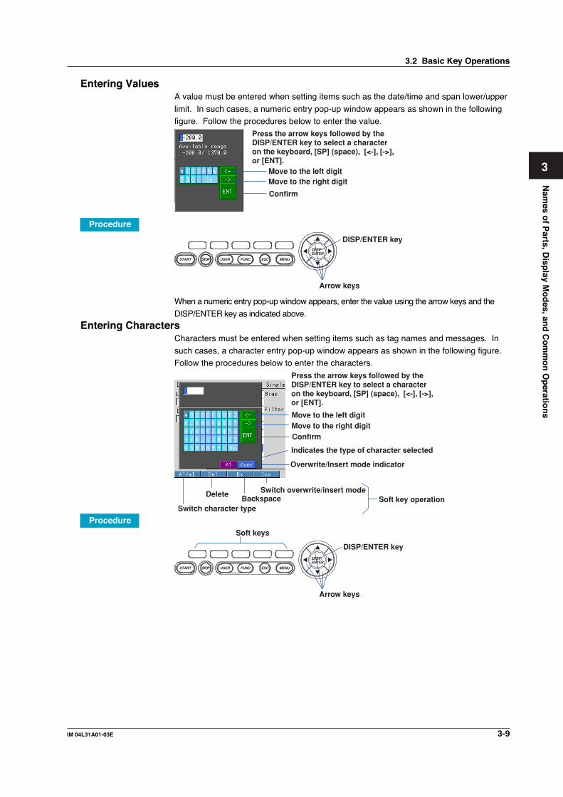
3-9IM 04L31A01-03E
Nam
es of P
arts, Disp
lay Mo
des, an
d C
om
mo
n O
peratio
ns
3
Entering ValuesA value must be entered when setting items such as the date/time and span lower/upper
limit. In such cases, a numeric entry pop-up window appears as shown in the followingfigure. Follow the procedures below to enter the value.
Press the arrow keys followed by theDISP/ENTER key to select a characteron the keyboard, [SP] (space), [<-], [->],or [ENT].
Move to the left digitMove to the right digit
Confirm
Procedure
DISP/ENTER
MENUESCFUNCUSERSTART STOP
Arrow keys
DISP/ENTER key
When a numeric entry pop-up window appears, enter the value using the arrow keys and the
DISP/ENTER key as indicated above.Entering Characters
Characters must be entered when setting items such as tag names and messages. In
such cases, a character entry pop-up window appears as shown in the following figure.Follow the procedures below to enter the characters.
Indicates the type of character selected
Overwrite/Insert mode indicator
Switch overwrite/insert modeBackspace
Delete
Switch character typeSoft key operation
Press the arrow keys followed by theDISP/ENTER key to select a characteron the keyboard, [SP] (space), [<-], [->],or [ENT].
Move to the left digitMove to the right digitConfirm
Procedure
DISP/ENTER
MENUESCFUNCUSERSTART STOP
Arrow keys
Soft keys
DISP/ENTER key
3.2 Basic Key Operations

3-10 IM 04L31A01-03E
When a character entry pop-up window appears, enter the value using the following keyoperation.
• Arrow keys: Selects characters, symbols, and operations.• DISP/ENTER key: Confirms the selected character, symbol, or operation.• [DEL] soft key: Clears the character at the cursor position.
• [BS] soft key: Clears the character before the cursor position.• [INS] soft key: Selects insert or overwrite.
Insert and overwrite mode toggles each time the [INS] soft key is pressed. The
selected mode is shown on the right side of the soft key display section.• [Copy/Paste] soft key: Used when copying character strings. Move the cursor to the
string to be copied and press the [Copy] soft key. Move the cursor to the copy
destination string entry box and press the [Paste] soft key.• [Clear] soft key: Used when clearing the character string. Move the cursor to the
string you wish to clear and press the [Clear] soft key.
• [A/a/1] soft key: Selects the upper-case A, lower-case a, or value 1.The character that can be enter changes in the order shown below each time the [A/a/1] soft key is pressed. However, characters that cannot be entered are skipped. The
selected character is shown on the right side of the soft key display section.Upper-case A → lower-case a → value 1
3.2 Basic Key Operations

3-11IM 04L31A01-03E
Nam
es of P
arts, Disp
lay Mo
des, an
d C
om
mo
n O
peratio
ns
3
3.3 Setting the Date and Time
This section explains how to set the date, time, and the daylight savings function of theCX1000 internal clock.
ProcedureOpening the Setting Display
• Setting the Date and Time and the Daylight Savings TimePress the keys in the following sequence:
MENU key (switch to Set mode (Control)) > MENU key (switch to Set mode) > #8soft key (select [Time])From the operation display, use the above keys to open the Time set dialog box.
• Setting Daylight Savings TimePress the keys in the following sequence:
MENU key (switch to Set mode (Control)) > MENU key (switch to Set mode) > #6soft key (select [File,DST])The following display appears.
Setup Procedure• Setting the Date and Time
1. Press the [Input] soft key.
The cursor (blue) moves to the [YY] section.2. Enter the date/time using the arrow keys and the DISP/ENTER key.
When you start to press the keys, the word [Input] disappears from the soft key.
3. Select [ENT] on the Time set pop-up window and then press the DISP/ENTERkey to set the time.When the time is set, the word [Input] appears on the soft key.
To cancel the settings and close the Time set pop-up window, press the ESC key.

3-12 IM 04L31A01-03E
• Setting Daylight Savings Time1. Use the arrow keys to move the cursor (blue) to the item box you wish to change.
A soft key menu is displayed at the bottom of the display.2. Press the soft key corresponding to the value you wish to select.
The box for the item you changed turns yellow, and the cursor moves to the next item.
3. Repeat steps 1 and 2 to change the value of all the items you wish to change.4. Press the DISP/ENTER key to confirm the changes.
The boxes for the items you changed turn from yellow to white, and the cursor
returns to the first item box.
Setup ItemsDaylight Savings Time• Summer/Winter
• Off/OnWhen set to [On], the daylight savings time is enabled.
• YY/MM/DD HHEnter the date and hour when the time is to be changed. The time is set ahead onehour at the date and hour specified for [Summer] and set back one hour at the dateand hour specified for [Winter].
3.3 Setting the Date and Time

3-13IM 04L31A01-03E
Nam
es of P
arts, Disp
lay Mo
des, an
d C
om
mo
n O
peratio
ns
3
3.4 Setting the Brightness of the Display and theBacklight Saver Function
This section explains how to set the brightness of the LCD and the backlight saver
function used to prolong the life of the LCD backlight.
ProcedureOpening the Setting Display
Press the keys in the following sequence:
MENU key (switch to Set mode (Control)) > MENU key (switch to Set mode) > #5soft key (select [Display]) > #4 soft key (select [View, Direction, LCD)The following setting display appears.
Setup Procedure1. Use the arrow keys to move the cursor (blue) to the [Brightness] or [Saver].
The selections are displayed at the bottom of the display.2. Press the soft key corresponding to the value you wish to change.
The box for the item you changed turns yellow, and the cursor moves to the next item.If [Backlight saver On/Off] is set to [On], [Saver time] and [Restore] entry boxes appear.
3. Repeat steps 1 and 2 to change the value of all the items you wish to change.4. Press the DISP/ENTER key to confirm the changes.
The boxes for the items you changed turn from yellow to white, and the cursorreturns to the first item box.
Setup ItemsDisplay BrightnessSelect a value from “1 to 8” (the initial setting is 4). The larger the value, the brighter thedisplay becomes.Backlight Saver Function• Saver
When set to [On], the LCD backlight automatically dims according to the specifiedconditions described below.
• Saver timeSelect a value from “1min, 2min, 5min, 10min, 30min, 1h” (factory default setting is 1h). If thespecified time elapses without any key operation, the LCD backlight is automatically dimmed.
• RestoreKey: The backlight returns to the original brightness on a key operation.Key + Alm: The backlight returns to the original brightness on a key operation or an
alarm occurrence.
NoteThe degradation of the brightness and the discoloration of the screen (become yellowish)tend to progress faster as the brightness is set higher. Extended use at an unnecessary highsetting should be avoided. It is also recommended that you use the backlight saver function.

3-14 IM 04L31A01-03E
3.5 Initializing the Setup Data and Clearing theInternal Memory
This section explains how to initialize the setup data in the internal memory to factory
default settings (initial settings) and how to clear the data in the internal memory. For alist of initial settings, see appendix 6.
ProcedureOpening the Setting Display
Press the keys in the following sequence:MENU key (switch to Setting mode (Control)) > Hold down the FUNC key for 3seconds (switch to basic setting mode) > #7 soft key (select [Load, Initialize]) > #4(select [Initialize])The following setting display appears.
Setup Procedure1. Use the arrow keys to move the cursor (blue) to the item box you wish to change.
The selections are displayed at the bottom section of the display.
2. Press the soft key corresponding to the value you wish to change.The box for the item you changed turns yellow, and the cursor moves to the next item.
3. Repeat steps 1 and 2 to change the value of all the items you wish to change.
4. Press the DISP/ENTER key to confirm the changes.The boxes for the items you changed turn from yellow to white, and the cursorreturns to the first item box.
Saving the Settings1. Press the ESC key.
The display returns to basic setting menu.
2. Press the [End] soft key.A confirmation dialog box appears.
3. Select [Yes] and press the DISP/ENTER key.
Setup ItemsSelect the type of operation from the following:Clear1: Initializes the setup data of basic setting mode and setting mode and clears the
data in the internal memory.
Clear2: Initializes the setup data of setting mode and clears the data in the internal memory.Clear3: Clears the data in the internal memory.Data That Are ClearedItems that are cleared are, display data, event data, manual sample data, TLOG data(option), report data (option), and log information.

3-15IM 04L31A01-03E
Nam
es of P
arts, Disp
lay Mo
des, an
d C
om
mo
n O
peratio
ns
3
3.6 Changing the Displayed Language
This section explains how to change the language used on the display.
ProcedureOpening the Setting Display
Press the keys in the following sequence:MENU key (switch to Setting mode (Control)) > Hold down the FUNC key for 3seconds (switch to basic setting mode) > #11 soft key (select [Aux, Time zone])
The following setting display appears.
Setup Procedure1. Use the arrow keys to move the cursor (blue) to the [Language] box.
[English], [Japanese], [German], [French], and [Chinese] appear in the soft keymenu at the bottom of the display.
2. Press the [English], [Japanese], [German], [French], or [Chinese] soft key.The [Language] box turns yellow, and the cursor moves to the next item.
3. Press the DISP/ENTER key to confirm the changes.
The boxes for the items you changed turn from yellow to white, and the cursorreturns to the first item box.
Saving the Settings1. Press the ESC key.
The display returns to basic setting menu.
2. Press the [End] soft key.A confirmation window appears.
3. Select [Yes] and press the DISP/ENTER key.

3-16 IM 04L31A01-03E
3.7 Changing the Time Zone
This section explains how to set the time difference with respect to Greenwich MeanTime. Make sure to set this value if you are using the Web server function.
ProcedureOpening the Setting Display
Press the keys in the following sequence:MENU key (switch to Setting mode (Control)) > Hold down the FUNC key for 3seconds (switch to basic setting mode) > #9 soft key (select [Aux, Time zone])The following setting display appears.
Setup Procedure1. Use the arrow keys to move the cursor (blue) to the [Difference from GMT] box
under [Time zone].
[Input] is displayed at the bottom of the display.2. Press the [Input] soft key.3. Enter the time difference using the character/number input keys and soft keys.
4. Press the DISP/ENTER key.5. Press the DISP/ENTER key to confirm the changes.
Saving the Settings1. Press the ESC key.
The display returns to basic setting menu.
2. Press the [End] soft key.A confirmation window appears.
3. Select [Yes] and press the DISP/ENTER key.
Setup ItemsSet the time difference with respect to Greenwich Mean Time from –1200 to 1200 (the
upper two digits indicate the hour; the lower two digits indicate the minute).Example: The standard time in Japan is ahead of the Greenwich Mean Time by 9 hours.In this case, enter “900.”

3-17IM 04L31A01-03E
Nam
es of P
arts, Disp
lay Mo
des, an
d C
om
mo
n O
peratio
ns
3
3.8 Inserting and Ejecting the External StorageMedium
This section explains how to insert and eject the external storage medium. You can use
one of three types of external storage medium: floppy disk, Zip disk, or ATA flashmemory card. The type of external storage medium is specified at the time of purchase.
CAUTION• If you turn ON/OFF the CX1000 while a Zip disk is inserted in the drive, the Zip
drive may malfunction. When turning ON/OFF the CX1000, first remove the Zipdisk from the drive.
• Do not eject the external storage medium while the access lamp is illuminated.This can damage the data.
• Do not operate the floppy disk drive or Zip drive in a place with vibrations or
shock. The disk or drive may malfunction.
For other information regarding the handling of the external storage medium, see section2.1, “Handling Precautions.”
ProcedureInserting the External Storage Medium
1. Open the front cover by pressing down on the knob that is located in the center ofthe upper section of the cover and pulling it forward.
Insert the external storage medium into the drive and press it until it clicks into place.
Floppy disk(2HD)
Zip disk(100 MB)
ATA flash memory card(4 to 440 MB)
2. When the power switch is turned ON, closing the front cover causes the CX1000 tosearch for an external storage medium in the drive. If the external storage mediumis detected, an icon indicating the existence of the external storage medium
appears in the status display section of the display.
External storage medium icon
Icon indicating that the operationcover is open
NoteKeep the operation cover closed at all times during operation except when inserting or
ejecting the external storage medium. The operation cover protects the external storage
medium and the drive from foreign particles such as dust.

3-18 IM 04L31A01-03E
Ejecting the External Storage MediumZip disks cannot be removed when the CX1000 is turned OFF. Floppy disks and ATA
flash memory cards can be removed from the drive regardless of whether the CX1000is turned ON or OFF.1. If the CX1000 is turned ON, check that the external storage medium is not being
accessed.
Note• The access lamp illuminates while the external storage medium is being accessed.
• If the data in the internal memory is being saved to the external storage medium, the
message “Data are being saved to the medium” appears.
2. Open the front cover by pressing down on the knob that is located in the center ofthe upper section of the cover and pulling it forward.
3. Press the eject button and remove the external storage medium.4. Close the operation cover.
If the CX1000 is turned ON, the external storage medium icon in the status display
section disappears.
Floppy disk Zip disk ATA flash memory card
NoteIf you are using a Zip disk and the ejection of the Zip disk is prohibited by the key lock
function, you cannot eject the Zip disk using the eject button. Clear the key lock before
removing the Zip disk. For the procedure in clearing the key lock, see section 11.2, “Key
Lock.”
Procedure When the Zip Disk Cannot Be EjectedIf the Zip disk cannot be removed by performing the steps given in “Ejecting theExternal Storage Medium,” carry out the following steps to eject it.1. Open the front cover by pressing down on the knob that is located in the center of
the upper section of the cover and pulling it forward.2. Insert a pin with a diameter of around 1 mm into the eject button hole and slowly
press the pin in.
The Zip disk will be ejected.
Eject button of the Zip drive
Insert a pin.
Zip disk eject hole
3.8 Inserting and Ejecting the External Storage Medium

3-19IM 04L31A01-03E
Nam
es of P
arts, Disp
lay Mo
des, an
d C
om
mo
n O
peratio
ns
3
Setup ItemsFormatting the External Storage MediumUse a formatted external storage medium.The CX1000 formats external storage media as follows (for the procedure in formatting
the external storage medium, see page 9-11).Floppy disk: 2HD, 1.44 MB.Zip disk: FDISK 1 partition (hard disk format).
ATA flash memory card: FDISK 1 partition (hard disk format).External storage media that are formatted using other instruments can be used on theCX1000, if the format is the same. External storage media of formats other than those
listed above cannot be used.
3.8 Inserting and Ejecting the External Storage Medium

4-1IM 04L31A01-03E
Co
ntro
l Fu
nctio
n R
elated S
etup
Op
eration
s
4
Chapter 4 Control Function Related Setup Operations
4.1 Control > Control action
This section explains the procedures for setting control operation related parameterssuch as control cycle, zone PID selection, and control mode.
ProcedureOpening the Setting Display
Press the keys in the following sequence:MENU key (switch to Setting mode (control)) > Hold down the FUNC key for 3seconds (switch to basic setting mode) > #12 soft key (select [Control]) #1 soft key(select [Control action])The following setting display appears (When PV/SP computation is OFF).
Setup Procedure1. Use the arrow keys to move the cursor (blue) to the item box you wish to change.
A soft key menu is displayed at the bottom of the display.2. Press the soft key corresponding to the value you wish to select.
The box for the item you changed turns yellow, and the cursor moves to the next item.
3. Repeat steps 1 and 2 to change the value of all the items you wish to change.4. Press the DISP/ENTER key to confirm the changes.
The boxes for the items you changed turn from yellow to white, and the cursor
returns to the first item box.
Saving the Settings1. Press the ESC key.
The display returns to basic setting menu.2. Press the [End] soft key.
A confirmation dialog box appears3. Select [Yes] and press the DISP/ENTER key.
The operation screen is displayed.
If you change any of the parameters [PID number], [Control period], [Control mode], or[Program control], a message “Initialize setting data” appears in the confirmation window.When you press the DISP/ENTER key, setup items of [Setting mode (Control)] related to
these settings (see Note on page 4-3) will be initialized.
Setup ItemsSetting Control Action Related Parameters• PID number
Set the maximum control parameter group number to be used in the range of [1] to [8](initial value is 8).
• Control periodSelect the control cycle from [250ms], [500ms], and [1s] (initial value is 250ms). However, ifbasic setting mode > [#2 A/D, Temperature] > [A/D Integrate] in basic setting mode is set to[100ms], the control period is fixed to [1s] and is not selectable.

4-2 IM 04L31A01-03E
• Zone PIDSet the PID selection method by turning [Off]/[On] the Zone PID.
Off (initial value): Target setpoint selectionIf program control is ON on models with the program control option,this becomes “segment PID.”
On: Zone PIDFor the procedure in setting the reference point of the zone PID,see section 4.10, “Operation-related parameters/Zone PID.”
• Restart mode• Fixed-pointSelect the action of the fixed-point control loop after recovering from an extended
power failure from [Continue], [Manual], [Auto] (initial value is Continue).Continue: Continue the operation before the power failure occurred.Manual: Start from a manual operation condition (control output is set to preset output).
Auto: Start from an auto operation condition (start the control output from presetoutput and resume control computation based on the preset output).
• Program ← Only on models with the program control option
Select the restart mode (recovery behavior) the CX1000 will enter when recoveringfrom a power failure when program operation is performed. Select [Continue],[Manual], or [Reset] (initial value is Continue).
Continue: Continue the operation before the power failure occurred.Manual: Start from a manual operation condition (control output is set to preset output).Reset: Start program operation from a reset condition (control output is set to
preset output).• Initial PID
Select [Temp] or [Press+Flow] (initial value is Temp) for the initial value of the PID
constant (see page 4-28). Below are the initial values of PID constants. The PIDconstant is also initialized to the following value when [Initial PID] is changed.Initial values for temperature: P = 5.0%, I = 240 s, and D = 60 s.
Initial values for pressure flow: P = 120.0%, I = 20 s, and D = 0 s.• Auto tuning
Select [On] (initial value is Off) to enable the auto-tuning function of the PID constant.
• Loop numberThe [Control mode], [Program control], and [PID control mode] parameters are set foreach loop. When changing these parameters, this setting is used to select the target
loop number [1] or [2] (initial value is 1).• Control mode
Select a control mode of [Single], [Cascade], [PVSwitching] (initial value is Single), or
[Retrans] (Style Number S3 or later). Select [Off] for the loops that are not to be controlled.Different control modes (except for [Retrans]) cannot be specified on the two loopswithin the single control output terminal block. If you specify [Cascade], both loops
are set to [Cascade].• Method (set only when the control mode is set to [PVSwitching])
Select the switching condition of the two PV inputs from [Range], [PVHigh], and
[Signal].• Program control (set only on models with the program control option)
Turns [On]/[Off] program control (initial value is Off). This setting applies to both loops
within the single control output terminal block. This setting is invalid for loops whichthe control mode is set to [Off] or [Retrans] (Style Number S3 or later).
• PID control modeSelect either [Follow-up] or [Fixed-point]. This setting is invalid for loops whosecontrol mode is set to [Off] or [Retrans] (Style Number S3 or later).
4.1 Control > Control action

4-3IM 04L31A01-03E
Co
ntro
l Fu
nctio
n R
elated S
etup
Op
eration
s
4
Contents Initialized during Setting ChangesIf you change the PID group number or control mode setting, the following items under
setting mode (control) are initialized.PID numberThe following items are initialized.
• Segment PID group number[Control mode]Items other than the following are initialized.
• Tag, tag comment• [#5 Control group setting]• [#8 Detailed (DIO monitor and operation, etc...) > [#3 DI/DO monitor and operation
setting]• [#8 Detailed (DIO monitor and operation, etc...) > [#4 DI/DO label setting]• [#9 Control math setting] > [#2 Logic math]
• [#9 Control math setting] > [#3 Constant]
4.1 Control > Control action

4-4 IM 04L31A01-03E
4.2 Control > Input setting (Burnout and RJC)This section explains the procedures for setting PV input burnout and reference junction
compensation.
ProcedureOpening the Setting Display
Press the keys in the following sequence:
MENU key (switch to Setting mode (control)) > Hold down the FUNC key for 3seconds (switch to basic setting mode) > #12 soft key (select [Control]) #2 soft key(select [Input setting])
The following setting display appears.
Setup Procedure1. Use the arrow keys to move the cursor (blue) to the item box you wish to change.
A soft key menu is displayed at the bottom of the display.
2. Press the soft key corresponding to the value you wish to select.The box for the item you changed turns yellow, and the cursor moves to the next item.
3. Repeat steps 1 and 2 to change the value of all the items you wish to change.
NoteThe reference junction compensation voltage is set using the pop-up window that appears by
pressing the [Input] soft key.
4. Press the DISP/ENTER key to confirm the changes.The boxes for the items you changed turn from yellow to white, and the cursorreturns to the first item box.
Setup ItemsSetting Input-Related ParametersThe setting menu differs when the PV/SP computation function is ON or OFF.• Loop number (first and last channel when the PV/SP computation function is ON)
Set the [Burnout] and [RJC] parameters for each loop. When changing these
parameters, this setting is used to select the target loop number [1] or [2] (initial valueis 1). The loop number is displayed up to the number of loops you specified at thetime of purchase.
When the PV/SP computation function is ON, you can set the control input channelnumber.
• BurnoutSets the burnout action for the PV inputs of each loop. [Measure2] is valid only whenthe control mode is set to [PVSwitching]; [Remote] is valid only when the PV input isset to remote input. This setting is invalid for PV inputs other than thermocouples and
standard signals.

4-5IM 04L31A01-03E
Co
ntro
l Fu
nctio
n R
elated S
etup
Op
eration
s
4
• Measure1/Measure2/RemoteSelect [Off], [Up], or [Down] (initial value is Up) according to the description given
below.Off: Burnout action OffUp: When a burnout occurs, the measured result is set to positive overrange
“+*****.”Down: When a burnout occurs, the measured result is set to negative overrange
“–*****.”
When the PV/SP computation function is ON, you can turn the buffer for the controlinput channel ON or OFF. When ON, the measured results are fixed according tothe settings in PV/SP computation error. For information about PV/SP computation
error see section 4.16, “PV/SP Computation and Analog Retransmission Settings(Style Number S3).”
• RJCThis is the reference junction compensation setting for thermocouple inputs. Thesetting is entered on the PV inputs of each loop. [Measure2] is valid only when thecontrol mode is set to [PVSwitching]; [Remote] is valid only when the PV input is set to
remote input. This setting is invalid for PV inputs other than thermocouples.• Measure1/Measure2/Remote
Select either [Internal] or [External] (initial value is Internal).
Internal: Uses the reference junction compensation function of the CX1000.External: Uses an external reference junction compensation function.If set to [External], a box for entering the reference junction compensation voltage
that is added to the input appears. Set the value in the range of [–20000] µV to[20000] µV (initial value is 0 µV).
When the PV/SP computation function is ON, you can select Internal or External
(default value is Internal) for the control input channel. If set to External, a setting boxfor the reference junction compensation voltage that is added to the input is displayed.The setting range is –20000 µV to 20000 µV (default value is 0 µV). 4.2 Control >
Input setting (Burnout and RJC)This section explains the procedures for setting PV input burnout and reference junctioncompensation.
• RJCThis is the reference junction compensation setting for thermocouple inputs. Thesetting is entered on the PV inputs of each loop. [Measure2] is valid only when the
control mode is set to [PVSwitching]; [Remote] is valid only when the PV input is set toremote input. This setting is invalid for PV inputs other than thermocouples.• Measure1/Measure2/Remote
Select either [Internal] or [External] (initial value is Internal).Internal: Uses the reference junction compensation function of the CX1000.External: Uses an external reference junction compensation function.
If set to [External], a box for entering the reference junction compensation voltagethat is added to the input appears. Set the value in the range of [–20000] µV to[20000] µV (initial value is 0 µV).
4.2 Control > Input setting (Burnout and RJC)

4-6 IM 04L31A01-03E
4.3 Control > DI/DO/SW-registrationThis section explains the procedures for registering the contact input information during
control, selecting remote inputs, and setting the alarm mode.
ProcedureOpening the Setting Display
Press the keys in the following sequence:
MENU key (switch to Setting mode (control)) > Hold down the FUNC key for 3seconds (switch to basic setting mode) #12 soft key (select [Control]) > #3 soft key(select [DI/DO/SW-registration])
The following setting display appears.
Setup Procedure1. Use the arrow keys to move the cursor (blue) to the item box you wish to change.
A soft key menu is displayed at the bottom of the display.
2. Press the soft key corresponding to the value you wish to select.The box for the item you changed turns yellow, and the cursor moves to the nextitem.
3. Repeat steps 1 and 2 to change the value of all the items you wish to change.
4. Press the DISP/ENTER key to confirm the changes.The boxes for the items you changed turn from yellow to white, and the cursorreturns to the first item box.
Saving the Settings1. Press the ESC key.
The display returns to basic setting menu.2. Press the [End] soft key.
A confirmation dialog box appears
3. Select [Yes] and press the DISP/ENTER key.The operation screen is displayed.

4-7IM 04L31A01-03E
Co
ntro
l Fu
nctio
n R
elated S
etup
Op
eration
s
4
Setup ItemsRegistering Contact Inputs• Module
Select the terminal block for contact input settings from the list below. The contact
input number in the Relay Operation settings field will change per the selectedterminal block.CTRL1-DI (control output terminal block 1): DI001–DI006CTRL1-DO (control output terminal block 1): DO101-DO106INT-SW1 (internal switch): SW01-SW 6INT-SW2 (internal switch): SW7-SW12INT-SW2 (internal switch): SW13-SW18For a description on the terminal arrangement, see page 2-6 to 2-7.
Set the contact input information for each contact input terminal(DI001 to DI006) of thecontrol ouput terminal block. For a description of the terminal arrangement, see page 2-6.
• Contact input information registrationSelect the contact input information for each contact input registration number from thefollowing. For a description on the method of detecting contact inputs, see page 1-24.• AllControlStop
Select this when registering as a contact input for stopping the control operation ofall internal loops.
• AllControlStartSelect this when registering as a contact input for starting the control operation ofall internal loops.
• ControlStart/Stop (1 and 2)Select this when registering a contact input for starting the control operation of eachinternal loop. The rising edge of the signal signifies “Stop”; the falling edge of thesignal signifies “Run.”For a control output terminal block, up to two loops that can output signals can beregistered per block. In the cascade mode, registration is allowed only for loops 2.
• Remote/Local (1 and 2)Select this when registering a contact input for switching remote operation and localoperation for each internal loop. The rising edge of the signal signifies “Remote”; thefalling edge of the signal signifies “Local.”If program control is ON (only on models with the program control option), switching isperformed between program operation and local operation.In the cascade mode, registration is allowed only for loops 1 and 3.
• Auto/Man (1 and 2) ← not selectable during cascade controlSelect this when registering a contact input for switching auto and manual (Man)operation for each internal loop. The rising edge of the signal signifies “Auto”; thefalling edge of the signal signifies “Man.”
• Cascade1-2 ← selectable only during cascade control.Select this for internal loops 1-2 when registering a contact input for switching fromauto operation or manual operation to cascade operation.
Note[Cascade1-2] does not appear as a selection, if the [Control mode] box under [Control] > [#1
Control action, Input setting] is not set to [Cascade].
4.3 Control > DI/DO/SW-registration

4-8 IM 04L31A01-03E
• Auto1-2 ← selectable only during cascade control.Select this for internal loops 1-2 when registering a contact input for switching from
cascade operation or manual operation to auto operation.• Man1-2 ← selectable only during cascade control.
Select this for internal loops 1-2 when registering a contact input for switching from
cascade operation or auto operation to manual operation. A single registration ispossible per control output terminal block. This setting is not allowed for controloutput terminal block 3.
• SPNumber0 to 3 bitSelect when registering a contact input for switching the SP. Four contact inputs (4-bit binary) are used to specify SP numbers [1] to [8]. For example, set SPnumber1bit
and SPnumber2bit to ON to specify SP number [6].Contact outputs that can be registered to [SPnumber0bit] to [SPnumber3bit] are[DI003 to DI006] of loop 1 and 2 control output terminal block and [RI009 to RI012]
of the control DIO expansion terminal block. Only the required number of bits canbe registered. For example, if you are switching among SP numbers [1] to [3],register only [SPnumber0bit] and [SPnumber1bit] (2 bits).
If [SPnumber0bit] through [SPnumber3bit] that corresponds to the MSB is set to[DI006] of control output terminal block, the required number of bits of contactinputs—[DI003 to DI006] for the control output terminal block—are automatically
registered.Note
• For contact inputs [SPnumber0bit] to [SPnumber3bit], the loop number for which the SP
number is to be switched can be selected. For the operating procedure, see the
explanation for [SP No. selection source] on page 4-12.
• Only a single system of SP assignment using contact inputs is available on each CX1000.
• ProgramRun ← selectable only during program controlSelect to register a contact input for starting the program operation.
• ProgramReset ← selectable only during program controlSelect to register a contact input for resetting the program operation.
• Hold ← selectable only during program control
Select to register a contact input for holding the program operation.• Advance ← selectable only during program control
Select to register a contact input for advancing the program operation.
• PatternNo0 to 4bit ← selectable only during program controlWhen registering as a contact input for switching the program pattern.When specifying program pattern numbers in binary5 contact inputs (5-bit binary) are used to specify the pattern number (1 to 30). Forexample, set [PatternNo1bit] and [PatternNo2bit] to ON to specify pattern number [6].Contact outputs that can be registered to [PatternNo0bit] to [PatternNo4bit] are
[DI001 to DI005] of the control output terminal block. Only the required number ofbits can be registered. For example, if only 2 bits are needed to make the switch,register only [PatternNo0bit] and [PatternNo1bit].
If you place the cursor on [DI001] and press the soft key that includes themaximum pattern number to be specified, contact inputs of the required number ofbits, [DI001]-[DI005], are automatically registered.
When specifying program pattern numbers in binary-coded decimal (BCD)D64(version 3.20 or later)For the setting procedure, see section 4.21, “Settings for Switching the Program
Patterns Using Contact Inputs with BCD Codes (Version 3.20 or Later).”
4.3 Control > DI/DO/SW-registration

4-9IM 04L31A01-03E
Co
ntro
l Fu
nctio
n R
elated S
etup
Op
eration
s
4
• PVSwitching (1 and 2) ← Selectable only during loop control with PV switchingSelect to register a contact input for switching the input for each internal loop during
loop control with PV switching. The rising edge signifies “PV2”; the falling edgesignifies “PV1.”
Note[PVSwitching1] or [PVSwitching2] does not appear as a selection, if the [Control mode] box
under [Control] > [#1 Control action, Input setting] is not set to [PVSwitching].
• MemoryStart/Stop
Starts/stops the acquisition of the display data/event data to the internal memory andthe report function (computation option function). The rising edge of the signalindicates start; the falling edge indicates stop.
If data acquisition is started, applying a rising signal produces no effect. Likewise, ifdata acquisition is stopped, applying a falling signal produces no effect..
• Trigger
Acts as an external trigger used to start the acquisition of event data to the internalmemory when in trigger mode or rotate mode. Input a signal for at least 250 ms.
• AlarmACK
Clears the alarm indication and relay output. This is the same function as when the[AlarmACK] soft key is pressed. Input a signal for at least 250 ms.
• TimeAdjust
Adjusts the internal clock of the CX1000 to the nearest hour depending on the timewhen the remote signal is applied. Input a signal for at least 250 ms.Time the signal is input Time modification
00 min 00 s to 01 min to 59 s Truncates the minutes and seconds.Example: 10 hours 01 min 50 s becomes 10 hours 00 min 00 s.02 min 00 s to 57 min to 59 s The time is not changed.
58 min 00 s to 59 min to 59 s Rounds up the minutes and seconds.Example: 10 hours 59 min 50 s becomes 11 hours 00 min 00 s.
• MathStart/Stop
Starts/stops the computation. The rising edge of the signal indicates start; thefalling edge indicates stop. This is valid only on models with the computationfunction option (/M1).
• MathResetResets the data on all computation channels. Input a signal for at least 250 ms.This is valid only on models with the computation function option (/M1) and while
the computation is stopped.• ManualSample
Write the instantaneous values of all channels to the internal memory once. Input
a signal for at least 250 ms. This excludes measurement channels set to skip andcomputation channels set to Off.
• Panel1Load to Panel3Load
Loads the setup data file named [LOAD1.PCL], [LOAD2.PCL], or [LOAD3.PCL] stored onthe external storage medium and activates the settings. Input a signal for at least 250 ms.Setup data files named [LOAD1.PCL], [LOAD2.PCL], or [LOAD3.PCL] must be created
and saved to the external storage medium beforehand.• Message1 to 8
Displays a message at the position corresponding to the time when the signal was
applied on the trend display. The displayed message is also written to the internalmemory. Input a signal for at least 250 ms.
4.3 Control > DI/DO/SW-registration

4-10 IM 04L31A01-03E
• SnapshotSaves the current screen image data to the external storage medium. Input a
signal for at least 250 ms.The snapshot function operates in all modes (operation mode, setting mode, andbasic setting mode). Error messages, even if they are displayed, are not saved.
Note• On models with the /A6R or /A4FR measurement alarm option terminal block, the action
from [MemoryStart/Stop] to [Snapshot] can also be assigned to the measurement remote
input. For the procedure in assigning actions to the measurement remote input, see
section 11.5, “Measurement Remote Input Setting.”
• If you wish to carry out operation only using contact input, you can disable key operation
such as by using the key lock function (see section 11.2)
4.3 Control > DI/DO/SW-registration

4-11IM 04L31A01-03E
Co
ntro
l Fu
nctio
n R
elated S
etup
Op
eration
s
4
4.4 Control > AUX (Remote setting, Alarm mode,SP No. selection source)
This section explains the procedures for selecting remote inputs, the alarm mode, and
the SP No. selection source.
ProcedureOpening the Setting Display
Press the keys in the following sequence:
MENU key (switch to Setting mode (control)) > Hold down the FUNC key for 3seconds (switch to basic setting mode) #12 soft key (select [Control]) > #4 soft key(select [AUX (Alarm mode...)])
The following setting display appears.
Setup Procedure1. Use the arrow keys to move the cursor (blue) to the item box you wish to change.
A soft key menu is displayed at the bottom of the display.
2. Press the soft key corresponding to the value you wish to select.The box for the item you changed turns yellow, and the cursor moves to the nextitem.
3. Repeat steps 1 and 2 to change the value of all the items you wish to change.
4. Press the DISP/ENTER key to confirm the changes.The boxes for the items you changed turn from yellow to white, and the cursorreturns to the first item box.
Saving the Settings1. Press the ESC key.
The display returns to basic setting menu.2. Press the [End] soft key.
A confirmation dialog box appears
3. Select [Yes] and press the DISP/ENTER key.The operation screen is displayed.

4-12 IM 04L31A01-03E
4.4 Control > AUX (Remote setting, Alarm mode, SP No. selection source)
Setup ItemsRemote setting, Alarm mode, and SP No. selection source• Loop number
The [Remote setting] and [Alarm mode] parameters are set for each loop. When
changing these parameters, this setting is used to select the target loop number [1] or[2] (initial value is 1).
• Remote setting ← only when program control is OFF
Select [Remote] (initial value is Off) to set the PV input to remote input. If [Control
mode] is set to [Cascade], this box is not displayed for the loop number of the
secondary loop.• Alarm mode
Select the condition for disabling the control alarm from the following. The characters
inside the parentheses are character strings displayed as selections in the soft keymenu.ALWAYS: Enable the alarm at all times.
STOP: Disable the alarm when the operation is stopped.STOP/MAN: Disable the alarm during manual operation mode or when the operation
is stopped.
• SP No. selection sourceSet the loop for switching the SP number using contact inputs [SPnumber0bit] to[SPnumber3bit] (see section 1.5). To apply the setting, select [On] (initial value is Off)
for each loop number [1] or [2].• PV/SP Computation Function
This setting determines whether or not the computed result is used for PV/SP. When
set to ON, you can specify an equation in the control setting mode to use for PV/SP.When the PV/SP computation function is ON, the following settings become active foreach control input channel.• Control input channel range settings
• Ten segment linearizer approximation settings• External RJC/burnout
If you change the PV/SP computation function, all but the following items under
setting mode (control) are initialized.• Tag, tag comment• [#5 Control group setting]
• [#8 Detailed (DIO monitor and operation, etc...) > [#3 DI/DO monitor and operationsetting]
• [#8 Detailed (DIO monitor and operation, etc...) > [#4 DI/DO label setting]
• [#9 Control math setting] > [#2 Logic math]• [#9 Control math setting] > [#3 Constant]• Settings for loops set for analog retransmission
• CLOG ErrorYou can set the method for handling abnormalities in the channel data for CLOG, aPV/SP computation operator.
Error: Process as a computation errorSkip: Skip any abnormal data and complete the computation
• Event output setting (Version 3.02 or later)Common: Set a common event output setting for all program patterns.Separate: Set the event output for each program pattern.

4-13IM 04L31A01-03E
Co
ntro
l Fu
nctio
n R
elated S
etup
Op
eration
s
4
4.5 Control > Output processing
This section describes the procedures for selecting the control output type, cycle time,and analog output. To perform ON/OFF control, set [Control output] to [On/Off-control].
ProcedureOpening the Setting Display
Press the keys in the following sequence:MENU key (switch to Setting mode (control)) > Hold down the FUNC key for 3seconds (switch to basic setting mode) > #12 soft key (select [Control]) #5 soft key(select [Output processing])The following setting display appears.
Setup Procedure1. Use the arrow keys to move the cursor (blue) to the item box you wish to change.
A soft key menu is displayed at the bottom of the display.2. Press the soft key corresponding to the value you wish to select.
The box for the item you changed turns yellow, and the cursor moves to the next
item.3. Repeat steps 1 and 2 to change the value of all the items you wish to change.4. Press the DISP/ENTER key to confirm the changes.
The boxes for the items you changed turn from yellow to white, and the cursorreturns to the first item box.
NoteThe [Cycle time] is set using the pop-up window that appears by pressing the [Input] soft key.
Saving the Settings1. Press the ESC key.
The display returns to basic setting menu.
2. Press the [End] soft key.A confirmation dialog box appears
3. Select [Yes] and press the DISP/ENTER key.
The operation screen is displayed.

4-14 IM 04L31A01-03E
Setup ItemsSetting Parameters Related to Output Processing• Loop number
Setup items of [Control output], [Cycle time] and [Analog-output type] are set for each
loop. When changing these parameters, this setting is used to select the target loopnumber [1] or [2] (initial value is 1).
NoteThe following item boxes do not appear, if the [Control mode] box under [Control] > [#1
Control action, Input setting] is set to [Cascade].
• Control outputSelect the type of control output from the following.• Relay
• Voltage-pulse• Current-output• On/Off-control (it cannot be set for loops whose control modes are set to analog
retransmission.)• Cycle time
Set the cycle time (control output cycle) for the time proportional PID in the range of
[1] s to [1000] s. This setting is valid only when [Control output] is set to [Relay] or[Voltage-pulse].
• Analog-output typeSelect the type of output current during current output from below. This setting is validonly when [Control output] is set to [Current-output].4-20mA, 0-20mA, 20-4mA, and 20-0mA
4.5 Control > Output processing

4-15IM 04L31A01-03E
Co
ntro
l Fu
nctio
n R
elated S
etup
Op
eration
s
4
4.6 Control > Relay
This section explains the procedures for setting the contact output for FAIL, selfdiagnosis, and display hold.
ProcedureOpening the Setting Display
Press the keys in the following sequence:MENU key (switch to Setting mode (control))) > Hold down the FUNC key for 3seconds (switch to basic setting mode) > #12 soft key (select [Control]) #6 soft key(select [Relay])The following setting display appears.
Setup Procedure1. Use the arrow keys to move the cursor (blue) to the item box you wish to change.
A soft key menu is displayed at the bottom of the display.2. Press the soft key corresponding to the value you wish to select.
The box for the item you changed turns yellow, and the cursor moves to the next
item.3. Repeat steps 1 and 2 to change the value of all the items you wish to change.4. Press the DISP/ENTER key to confirm the changes.
The boxes for the items you changed turn from yellow to white, and the cursorreturns to the first item box.
Saving the Settings1. Press the ESC key.
The display returns to basic setting menu.
2. Press the [End] soft key.A confirmation dialog box appears
3. Select [Yes] and press the DISP/ENTER key.
The operation screen is displayed.

4-16 IM 04L31A01-03E
Setup ItemsSetting Relay-Related ParametersSet the parameters for each contact output terminal (DO001 to DO006) of the controlouput terminal block. For a description of the terminal arrangement, see page 2-6.
• FAILThis is the setting for the function that outputs a relay contact signal (FAIL signal)
when a failure is detected in the CX1000 CPU. When set to [On] (initial setting is Off),“DO001” of control output terminal block 1 is automatically assigned to “de_energize/Nonhold.”
NoteFor the option terminal block with the FAIL output terminal (“/A4F” or “/A4FR” option), the
FAIL signal is output from the FAIL output terminal of the option terminal block.
• Self diagnosisThis is the setting for the function that outputs a relay contact signal when an inputburnout, A/D converter failure, or reference junction compensation failure occurs.
When set to [On] (initial setting is Off), “DO002” of control output terminal block 1 isautomatically assigned to “de_energize/Nonhold.”
• Relay (Action/Behavior)Select the relay action type of each contact output from the following:De_energize/hold, De_energize/Nonhold, Energize/Hold, and Energize/Nonhold
NoteThe behavior of the transistor (open-collector) output corresponding to the energize/
deenergize setting of the relay action is as follows:
When set to deenergize: Switch from On to Off during output
When set to energize: Switch from Off to On during output
4.6 Control > Relay

4-17IM 04L31A01-03E
Co
ntro
l Fu
nctio
n R
elated S
etup
Op
eration
s
4
4.7 Control > Tuning setting
This section explains the procedures for setting the parameters that are adjusted on thetuning display.
ProcedureOpening the Setting Display
Press the keys in the following sequence:MENU key (switch to Setting mode (control)) > Hold down the FUNC key for 3seconds (switch to basic setting mode) > #12 soft key (select [Control]) #7 soft key(select [Tuning setting])The following setting display appears.
Setup Procedure1. With the cursor (blue) located at the [Loop number] box, select the loop number for
setting the tuning parameter using the soft keys.The selected loop number is displayed in the [Loop number] box, and the cursormoves to the On/Off box of [1:].
2. Using the arrow keys, move the cursor to the On/Off box of the tuning parameteryou wish to change or the [Item name] box.The box for the item you changed turns yellow, and the cursor moves to the next item.
NoteThe [Item name] is set using the pop-up window that appears by pressing the [Detail] soft key.
On the pop-up window, set [Item ID] and [Item name]. Select [Item ID] using the soft key menu.
Enter [Item name] by pressing the [Input] soft key and using the character/number input keys.
3. Repeat steps 1 and 2 to change the value of all the items you wish to change.
4. Press the DISP/ENTER key to confirm the changes.The boxes for the items you changed turn from yellow to white, and the cursorreturns to the first item.

4-18 IM 04L31A01-03E
Saving the Settings1. Press the ESC key.
The display returns to basic setting menu.2. Press the [End] soft key.
A confirmation dialog box appears
3. Select [Yes] and press the DISP/ENTER key.The operation screen is displayed.
Setup ItemsSetting Tuning Parameters• Loop number
The parameters to be tuned are set for each loop. When changing these parameters,this setting is used to select the target loop number [1] or [2] (initial value is 1).
• On/OffSet the parameters that are to be displayed on the tuning display to [On]; set theparameters that are not to be displayed to [Off].
• Item nameUnder the initial settings, the tuning parameters are set as follows. The numbersindicate the order of items on the tuning display starting from the upper left corner.
The characters indicate the item names (tuning parameter name). In addition to thetuning parameters below, [DR] (control direction), [H] (relay hysteresis) BS1(measured value 1 input bias), FL1 (measured value 1 input filter), BS2 (measured
value 2 input bias), FL2 (measured value 2 input filter), RT (ratio setting), RBS(remote input bias), RFL (remote input filter), and W01-W12 (control computationconstant) are available. BS1-W12 is valid if the main unit is style number S3 or later.
are available.01: SP (target setpoint) 08: D (derivative time) 15: Off02: A1 (alarm value 1) 09: OH (High limit of the output limiter) 16: Off03: A2 (alarm value 2) 10: OL (Low limit of the output limiter) 17: Off
04: A3 (alarm value 3) 11: MR (manual reset) 18: Off05: A4 (alarm value 4) 12: PO (preset output) 19: Off06: P (proportional band) 13: Off 20: Off
07: I (integral time) 14: Off 21: OffSelect the [Item ID] from the 21 parameters listed above. [Item name] is a name thatcan be assigned to each parameter. You can use up to 6 alphanumeric characters to
specify a name. Under initial settings, [Item name] is set to the save character as theitem ID.
Note• The tuning parameters for external loops using Green series communications are set
using [Control] > [#8 Exteral loop setting] > [3# Tuning setting]. External loops have two
tuning parameters in addition to those listed above: [DB] and [ETC]. Furthermore, the
register address, the upper and lower limits of value range, and the decimal point position
can be changed for each tuning parameter in addition to the name.
• BS1, FL1, BS2, FL2, and RFL cannot be selected when the PV/SP computation is ON.
4.7 Control > Tuning setting

4-19IM 04L31A01-03E
Co
ntro
l Fu
nctio
n R
elated S
etup
Op
eration
s
4
4.8 Control input range
This section explains the procedures for setting PV input related parameters for thecontrol function such as range, span, scale, bias, and filter.
ProcedureOpening the Setting Display
Press the keys in the following sequence:MENU key (switch to setting mode (control)) > #1 soft key (select [Control input
range])The following display appears. The following figure is an example when [Controlmode] is set to [Cascade]
Setup Procedure1. Use the arrow keys to move the cursor (blue) to the item box you wish to change.
A soft key menu is displayed at the bottom of the display.2. Press the soft key corresponding to the value you wish to select.
The box for the item you changed turns yellow, and the cursor moves to the next
item box.3. Repeat steps 1 and 2 to change the value of all the items you wish to change.
NoteFor setup item boxes that require values to be entered, a pop-up window that appears by
pressing the [Input] soft key is used.
4. Press the DISP/ENTER key.A confirmation window appears. If you change any of the parameters besides[Bias] and [Filter], other parameters related to the changed parameter (see Note on
the next page) are initialized when you confirm the change. Consequently, amessage “Initialize the settings related to range” appears in the confirmationwindow as shown below.
5. Select [Yes] and press the DISP/ENTER key and confirm the changes.
The boxes for the items you changed turn from yellow to white, and the cursorreturns to the first item box.

4-20 IM 04L31A01-03E
Setup ItemsSetting Control Input Range Parameters• Loop number (control input channel when the PV/SP computation function is ON)
When the PV/SP computation function is OFF, you can set each setting item of the control
input range for each loop. When the PV/SP computation function is ON, you can set eachsetting item of the control input range for each loop. When changing these parameters,this setting is used to select the target loop number [1] or [2] (initial value is 1). The loop
number is displayed for the number of loops you specified at the time of purchase.• Input type (when PV/SP computation function is OFF)
Select the target input for making input range related settings from the following.
PV1, PV2, RemoteSP, and PVrange• Items [PV2] and [PVrange] appear only when [Control] > [#1 Control action, Input
setting] > [Control mode] is set to [PVSwitching]. If the measurement range of the
two input signals is different for the loop control with PV switching, make sure toselect [PVrange] to determine the PV range.
• Item [RemoteSP] appears only when [Control] > [#1 Control action, Input setting] >
[Program control] is set to [Off] and [Control] > [#4 AUX(Alarm mode...)] > [Remote setting]is set to [Remote]. For [PVSwitching], [RemoteSP] is selectable only on odd-numberedloops. In addition, for cascade control, item [RemoteSP] does not appear for the settings
of the loop number of the secondary loop.• Mode/Type/Range (setting when [Input type] is set to a type other than [PVrange])
Select the input mode [Mode] from [TC], [RTD], [Scale], and [1-5V]. Then, set other
items such as [Range] and [Span Lower/Upper-limit] according to the selected mode.• When set to TC (thermocouple)
Range Selectable Measurement Span Range
R 0.0 to 1760.0 °CS 0.0 to 1760.0 °CB 0.0 to 1820.0 °CK –200.0 to 1370.0 °CE –200.0 to 800.0 °CJ –200.0 to 1100.0 °CT –200.0 to 400.0 °CN 0.0 to 1300.0 °CW 0.0 to 2315.0 °CL –200.0 to 900.0 °CU –200.0 to 400.0 °CPLATI 0.0 to 1400.0 °CPR 0.0 to 1900.0 °CWRe 0.0 to 2400.0 °C
• When set to RTD (resistance temperature detector)
Range Selectable Measurement Span Range
Pt100 –200.0 to 600.0 °CJPt100 –200.0 to 550.0 °C
4.8 Control input range

4-21IM 04L31A01-03E
Co
ntro
l Fu
nctio
n R
elated S
etup
Op
eration
s
4
Note• The CX1000 converts the measured value to a value obtained by removing the decimal point
from the value range specified by [Scale Lower] and [Scale Upper]. In other words, if the [Scale]
setting is [–5] to [5], the value is converted to a value within the span of “10”; if the [Scale] setting is
[–5.0] to [5.0], the value is converted to a value within a span of “100.” In this case, the resolution
of the value converted to a span of “10” is lower than the value converted to a span of “100.”
• If you change any of the parameters [Mode], [Type], [Range], [Span Upper/Lower-limit], [Scale
Upper/Lower-limit], or [PV range Lower/Upper-limit], the following setup items (parameters set
using engineering units “EU” or “EUS”) related to these settings will be initialized.
Bias, alarm, SP ramp-down-rate, SP ramp-up-rate, reference point, switching hysteresis,
reference deviation, PID parameters, SP, relay hysteresis, ten-segment input, ten-
segment output, SP low-limit, SP high-limit, alarm hysteresis, and boundary of partial
expanded display.
• When set to ScaleSelect the [Type] (input type) from [DCV], [TC], and [RTD]. Then, set the [Range],
[Span Lower/Upper-limit], and the [Scale Lower/Upper-limit] and [Unit] after theconversion according to the selected [Type]. The selectable range for [TC] and[RTD] is the same as with the other inputs selected by [Mode]. The selectable
range of the scale is “–30000 to 30000.” The decimal place can be set to“X.XXXX,” “XX.XXX,” “XXX.XX,” “XXXX.X,” or “XXXXX.” The decimal place isdetermined by the scale low limit setting.
• Range and measurable range for voltage input
Range Selectable Measurement Span Range
20mV –20.00 to 20.00 mV60mV –60.00 to 60.00 mV200mV –200.0 to 200.0 mV2V –2.000 to 2.000 V6V –6.000 to 6.000 V20V –20.00 to 20.00 V50V –50.00 to 50.00 V
Note• Values such as alarm values are set using engineering units (EU or EUS) based on the
measurement span. For an explanation on engineering units (EU and EUS), see
appendix 8, “Explanation of Engineering Units (EU and EUS).”
• For current inputs, a shunt resistor is attached to the input terminal to convert the signal to
voltage input. The following table shows the available shunt resistors. For example, a
250-Ω shunt resistor is used to convert the signal to 1 to 5 V for 4-20 mA input.
Name Model Resistance
Shunt resistor 4159 20 250 Ω ± 0.1%
(for screw terminals) 4159 21 100 Ω ± 0.1%
4159 22 10 Ω ± 0.1%
• PV range Lower/Upper-limit (setting when [Input type] is set to [PVrange] during
loop control with PV switching)Set the value in the range [–30000] to [30000] (maximum value > minimum value,maximum value – minimum value ≤ 30000).
• PV switching Lower/Upper limit (setting when [Input type] is set to [PVrange])Set the value within the input range. If [Control] > [#1 Control action] > [Method] is setto [Range], set [PV switching Upper/Lower]; if [Method] is set to [PVHigh], set [PV
switching Upper] only.• Scale Lower/Upper-limit
Set the value in the range [–30000] to [30000] (maximum value > minimum value,
maximum value – minimum value ≤ 30000).
4.8 Control input range

4-22 IM 04L31A01-03E
• UnitYou can enter the unit using up to 6 alphanumeric characters.
• Square rootSet whether to perform square root computation on the PV input ([On]/[Off] (initial value)).
• Low-cutSet the low-cut point when the square root computation is On to [0.0 to [5.0]% (initialvalue is 1.0%).
• BiasSet bias to [On] (initial setting is Off) when adding a constant value (bias) to the PVinput. Set the bias value in the EUS range (–100% to 100%) of the measurementspan. For example, if the minimum and maximum values of the scale are [10.00] and
[200.00], respectively, the selectable range is “–190.00 to 190.00%.” The selectablerange is displayed in a pop-up window. Note that the bias can be changed during controloperation.
• FilterTurn ON/OFF the input filter and set the time constant when input filter is ON in the range of “1to 120 s.” Note that the time constant of the input filter can be changed during operation.
• Ratio (only when [Input type] is set to [RemoteSP]To multiply a certain ratio to the remote input, set this value to [On] and set the ratio in therange of “0.001 to 9.999.” Note that the ratio can be changed during control operation.
4.8 Control input range
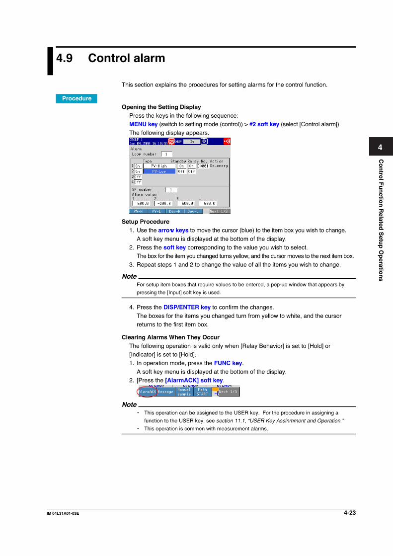
4-23IM 04L31A01-03E
Co
ntro
l Fu
nctio
n R
elated S
etup
Op
eration
s
4
4.9 Control alarm
This section explains the procedures for setting alarms for the control function.
ProcedureOpening the Setting Display
Press the keys in the following sequence:MENU key (switch to setting mode (control)) > #2 soft key (select [Control alarm])The following display appears.
Setup Procedure1. Use the arrow keys to move the cursor (blue) to the item box you wish to change.
A soft key menu is displayed at the bottom of the display.2. Press the soft key corresponding to the value you wish to select.
The box for the item you changed turns yellow, and the cursor moves to the next item box.
3. Repeat steps 1 and 2 to change the value of all the items you wish to change.
NoteFor setup item boxes that require values to be entered, a pop-up window that appears by
pressing the [Input] soft key is used.
4. Press the DISP/ENTER key to confirm the changes.
The boxes for the items you changed turn from yellow to white, and the cursorreturns to the first item box.
Clearing Alarms When They OccurThe following operation is valid only when [Relay Behavior] is set to [Hold] or[Indicator] is set to [Hold].1. In operation mode, press the FUNC key.
A soft key menu is displayed at the bottom of the display.2. [Press the [AlarmACK] soft key.
Note• This operation can be assigned to the USER key. For the procedure in assigning a
function to the USER key, see section 11.1, “USER Key Assinmment and Operation.”
• This operation is common with measurement alarms.

4-24 IM 04L31A01-03E
Setup ItemsSetting Control Alarms• Loop number
The setup items for control alarms are set for each loop. When changing these
parameters, this setting is used to select the target loop number [1] or [2] (initial valueis 1).
• Off/OnUp to four alarms can be registered per loop. Set only the alarms that are to be used to [On].
• TypeSelect the type of alarm from the following. Displayed symbols are indicated in
parentheses.PV high-limit alarm (PVH), PV low-limit alarm (PVL), deviation high-limit alarm (DVH),deviation low-limit alarm (DVL), deviation high & low limit alarm (DVO), deviation
within high & low limits alarm (DVI), SP high-limit alarm (SPH), SP low-limit alarm(SPL), output high-limit alarm (OTH), and output low-limit alarm (OTL).
• StandbyThis setting is valid when [Type] is set to [PV-High], [PV-Low], [Deviation-High],[Deviation-Low], [Deviation-H&L], or [Dev-within-H&L]. Set whether to standby ([On]or [Off]).
• Relay Output/NumberUp to four alarms can be registered per control loop. For each alarm, turn ON/OFFthe relay output and select the contact output number when using relay output from
the list below.DO001 to DO006SW001 to SW018: Internal switch (Style number S3 or later))
NoteThe contact output is output from the terminal indicated as [DIGITAL OUT] on the label on the
back of the terminal cover. For the relationship between the contact output numbers and the
[DIGITAL OUT] terminals of each terminal block, see page 2-6.
• ActionIndicates whether the relay output is energized or de-energized according to the[Relay(Action/Behavior)] setting under [Control] > [#6 Relay] (see page 4-16).
• SP number/Alarm valueThe control alarm outputs correspond to SP numbers [1] to [8]. Select the SP number[1] to [8] and register alarm values for the four alarms of each SP number. The
selectable alarm values vary depending on the specified [Type] (alarm type) as follows:PV high/low limits, SP high/low limits: EU of measurement span (0.0 to 100%)Deviation high/low limits: EUS of measurement span (–100 to 100%)
Deviation high/low limits, within deviation high and low limits: EUS of measurementspan (0 to 100%)Output value alarm: –5.0% to 105.0%
Clearing Alarms (AlarmACK)If the [AlarmACK] operation is performed, all alarm indications and relay outputs are
cleared. However, this operation is invalid if the alarm indication/output relay behavior isset to [Nonhold]. Alarms can be cleared using remote input (see section 11.5, “Settingthe Measurement Remote Inputs”) or via communications (see the CX1000/CX2000Communication Interface User’s Manual).
4.9 Control alarm

4-25IM 04L31A01-03E
Co
ntro
l Fu
nctio
n R
elated S
etup
Op
eration
s
4
4.10 Operation-related parameters/Zone PID
This section explains the procedures for setting the control output suppression function,control operation related parameters such as the ramp-rate-time unit, and zone PID
related parameters such as the reference point and zone switching hysteresis.
ProcedureOpening the Setting Display
Press the keys in the following sequence:
MENU key (switch to setting mode (control)) > #3 soft key (select [Operation-relatedparameters/Zone PID])The following display appears.
Setup Procedure1. Use the arrow keys to move the cursor (blue) to the item box you wish to change.
A soft key menu is displayed at the bottom of the display.2. Press the soft key corresponding to the value you wish to select.
The box for the item you changed turns yellow, and the cursor moves to the next
item box.3. Repeat steps 1 and 2 to change the value of all the items you wish to change.
NoteFor setup item boxes that require values to be entered, a pop-up window that appears by
pressing the [Input] soft key is used.
4. Press the DISP/ENTER key to confirm the changes.The boxes for the items you changed turn from yellow to white, and the cursorreturns to the first item box.

4-26 IM 04L31A01-03E
Setup ItemsSetting Operation-Related Parameters• Loop number
The setup items of “Operation-related parameters” are set for each loop. When
changing these parameters, this setting is used to select the target loop number [1] or[2] (initial value is 1).
• Suppressing functionSelect whether to use the overshoot suppressing function, [Overshoot] or [Off]. Thisfunction operates only during PID control. However, the function does not operate ifthe integral time or derivative time or both are set to [Off].
• Ramp-rate time unitSet the unit of time when setting a ramp grade per unit time to [Hour], [Minute], or[Second].
• SP ramp-down-rate/SP ramp-up-rateSet this item to [On] (initial setting is Off) to decrease or increase the setpoint at aconstant rate of change, as opposed to a rapid change, when the SP is changed.
When set to [On], set the value that is to change per ramp-rate-time unit in the rangeof “1 digit to EUS of measurement span (100%).”
• Tag/Tag commentSet the tag name or tag comment of each control loop using up to 8 alphanumericcharacters.
Setting Parameters Related to Zone PIDThese settings are possible only when [Zone PID] under [Control] > [#1 Control action] isset to [On].
• Loop numberThe setup items of zone PID method are set for each loop. When changing theseparameters, this setting is used to select the target loop number [1] or [2] (initial valueis 1).
• Reference pointSet the reference points for the zone PID method.The number of reference points that can be specified is “PID group number – 2.”
Reference points can only be specified when [PID number] is set to [3] or higher. Fora description on the settings of the number of PID groups, see section 4.1, “Control >Control action.”The selectable range of reference point values is shown using “EU (0.0 to 100.0%) ofthe measurement span) in a pop-up window. Reference points set up to 100% arevalid. Set the reference points so that 1 ≤ 2 ≤ 3 ≤ 4 ≤ 5 ≤ 6.
• Switching hysteresisSet the hysteresis used for switching zones at the reference points and deviation inthe range of “EUS (0.0 to 10.0%) of the measurement span” (initial value is 0.5%).
Can be specified when the [PID number] is set to 3 or greater. Can be specified whenthe [PID number] is set to 2 or greater.
• Reference deviationSet this value to [On] (initial value is Off) when selecting the PID value according tothe deviation from the SP (program setpoint). When set to [On], set the deviation inthe range of 1 digit to EUS (100.0%) of the measurement span. Can be specified
when the [PID number] is set to 2 or greater. Can be specified when the [PIDnumber] is set to 2 or greater.
4.10 Operation-related parameters/Zone PID

4-27IM 04L31A01-03E
Co
ntro
l Fu
nctio
n R
elated S
etup
Op
eration
s
4
4.11 PID parameters
This section explains the procedures for setting the PID control parameters of the controlfunction or the control parameters of the ON/OFF control.
ProcedureOpening the Setting Display
Press the keys in the following sequence:MENU key (switch to setting mode (control)) > #4 soft key (select [PID parameters])
The following display appears.• During PID control
• During ON/OFF control (when [Control] > [#5 Output processing] > [Control output]is set to [On/Off-control])
Setup Procedure1. Use the arrow keys to move the cursor (blue) to the item box you wish to change.
A soft key menu is displayed at the bottom of the display.2. Press the soft key corresponding to the value you wish to select.
The box for the item you changed turns yellow, and the cursor moves to the next item box.
3. Repeat steps 1 and 2 to change the value of all the items you wish to change.Note
For setup item boxes that require values to be entered, a pop-up window that appears by
pressing the [Input] soft key is used.
4. Press the DISP/ENTER key to confirm the changes.The boxes for the items you changed turn from yellow to white, and the cursor
returns to the first item box.

4-28 IM 04L31A01-03E
Setup ItemsSetting PID Parameters• Loop number
The setup items of PID parameters are set for each loop. When changing these
parameters, this setting is used to select the target loop number [1] or [2] (initial valueis 1).
NoteSome of the following parameter boxes do not appear, if [Control] > [#1 Control action] >
[Control mode] is set to [Cascade].
• PID numberSpecify the PID parameter group number [1] to [8]. The maximum selectable numberconforms to the [Control] > [#1 Control action] > [PID number] setting.
• SPSet the target setpoint (SP) in the range of “0 to 100% (EU (0 to 100%)) of themeasurement span” (initial value is 0%). However, this value is set within the highand low limits of the target setpoint limiter.
• PSet the proportional band in the range of [0.1] to [999.9]% (initial value for [Temp] is5.0%; initial value for [Press+Flow] is 12.0%).
• ISet the integral time in the range of [0] to [6000] s (initial value for [Temp] is 240 s;initial value for [Press+Flow] is 20 s).
• DSet the derivative time in the range of [0] to [6000] s (initial value for [Temp] is 60 s;initial value for [Press+Flow] is 0 s).
• Output lower/upper limitSet the low and high limits of the control output operation range in the range of [–5.0]% to [105.0%] (where high limit > low limit). The initial low limit value is [0.0]%;
the initial high limit value is [100.0]%.• Shutdown
When [Control] > [Output processing] > [Control output] is set to [Current-output] and
[Analog-output type] is set to [4-20mA] (see page 4-13), set whether the shutdownfunction is used ([On] (initial value) or [Off].
• M. resetFor the manual reset value, set the output value when the PV = the SP in the range of[–5.0] to [105.0]% (initial value is 50%). This setting is valid only when the integralaction (integral time) is set to Off.
• Relay hysteresisSet the hysteresis of the SP (or program setpoint) for ON/OFF control in the range of“EUS (0.0 to 100.0%) of the measurement span” (initial value is 0.5%). Then, set the
activation position of the hysteresis to [Mid], [High], or [Low] (initial setting is Mid).• R/D
Set the direction (increase or decrease) of the output corresponding to the polarity of
the deviation to [Reverse] (initial setting) or [Direct].• Preset
Set the fixed-point output value when the operation is stopped in the range of “–5.0 to
105.0%” (initial setting is 0.0%).
4.11 PID parameters

4-29IM 04L31A01-03E
Co
ntro
l Fu
nctio
n R
elated S
etup
Op
eration
s
4
4.12 Control group setting
This section explains the procedures for setting groups for the control function.
ProcedureOpening the Setting Display
Press the keys in the following sequence:MENU key (switch to setting mode (control)) > #5 soft key (select [Control groupsetting])
The following display appears.
Setup Procedure1. Use the arrow keys to move the cursor (blue) to the item box you wish to change.
A soft key menu is displayed at the bottom of the display.2. Press the soft key corresponding to the value you wish to select.
The box for the item you changed turns yellow, and the cursor moves to the nextitem box.
3. Repeat steps 1 and 2 to change the value of all the items you wish to change.
4. Press the DISP/ENTER key to confirm the changes.The boxes for the items you changed turn from yellow to white, and the cursorreturns to the first item box.
Setup ItemsControl group setting• Group number
Select the group number from four group numbers from [1] to [4].
• Group nameSet the group name using up to 16 alphanumeric characters.Group name display example
Group name

4-30 IM 04L31A01-03E
• On/OffUp to four members [1] to [4] can be assigned to a group. Set members that are not
to be displayed on the control group display to [Off].• Kind
Set the type of member to [Int-Loop], [Ext-Loop], [Meas-CH], or [DIO] (DIO monitor
and operation function).• Number
Select a number for each type set to the members. The selectable numbers are
displayed on the soft key menu according to the specifications of the CX1000 that youare using.Internal loop: 01 to 02
External loop: 01 to 04Measurement channel: 01 to 06DIO: 01 to 12
4.12 Control group setting

4-31IM 04L31A01-03E
Co
ntro
l Fu
nctio
n R
elated S
etup
Op
eration
s
4
4.13 Ten-segment linearizer I/O
This section explains the procedures for setting parameters related to the ten-segmentlinearizer output for the control function.
ProcedureOpening the Setting Display
Press the keys in the following sequence:MENU key (switch to setting mode (control)) > #6 soft key (select [Ten-segment
linearizer I/O])The following display appears.
Setup Procedure1. Use the arrow keys to move the cursor (blue) to the item box you wish to change.
A soft key menu is displayed at the bottom of the display.
2. Press the soft key corresponding to the value you wish to select.The box for the item you changed turns yellow, and the cursor moves to the nextitem box.
3. Repeat steps 1 and 2 to change the value of all the items you wish to change.
NoteFor setup item boxes that require values to be entered, a pop-up window that appears by
pressing the [Input] soft key is used.
4. Press the DISP/ENTER key to confirm the changes.
The boxes for the items you changed turn from yellow to white, and the cursorreturns to the first item box.

4-32 IM 04L31A01-03E
4.13 Ten-segment linearizer I/O
Setup ItemsTen-segment linearizer I/O• Loop number (control input channel number when the PV/SP computation
function Is ON)The setup items of ten-segment linearizer output parameters are set for each loop.When the PV/SP computation function is ON, you can set each setting item of the tensegment linearizer I/O settings for each control input channel.
When changing these parameters, this setting is used to select the target loopnumber [1] or [2] (initial value is 1).
• Input type (when PV/SP computation function is OFF)Only during loop control with PV switching, select [PV1] or [PV2]. During single loopcontrol and cascade control, only [PV1] is displayed.
• ModeWhen using the ten-segment linearizer approximation, set the mode to [Biasing] or[Approximation]. If not, set to [Off] (initial setting).
• Input/OutputIf you are using the ten-segment linearizer approximation, set between 2 to 11 pointsof input/output values. If the number of segmental points is less than 11, set the nextInput value of the next segmental point to the same value as (or a value less than) the
Input value of the final segment.The selectable range is indicated below.• For ten-segment linearizer bias
Selectable range of input value: EU (–5.0% to 105.0%) of the measurement span(initial value for points other than the second is0.0%, initial value for the second point is 100%)
Selectable range of output value: EUS (–100.0% to 100.0%) of the measurementspan (initial value is 0.0%)
The selectable range is displayed in a pop-up window.
• For ten-segment linearizer approximationSelectable range of input value: EU (–5.0% to 105.0%) of the measurement span
(initial value for points other than the second is
0.0%, initial value for the second point is 100%)Selectable range of output value: EU (–5.0% to 105.0%) of the measurement span
(initial value is 0.0%)
The selectable range is displayed in a pop-up window.

4-33IM 04L31A01-03E
Co
ntro
l Fu
nctio
n R
elated S
etup
Op
eration
s
4
4.14 Control Function Settings
This section explains the setting procedure for the control function.
ProcedureOpening the Setting Display
Press the keys in the following sequence:MENU key (switch to setting mode(control)) > #7 soft key (select [Detailed setting](DIO monitor and operation, etc...), #8 soft key when program control is ON) > #1soft key (Control function)The following display appears.
Setup Procedure1. Use the arrow keys to move the cursor (blue) to the item box you wish to
change.
A soft key menu is displayed at the bottom of the display.2. Press the soft key corresponding to the value you wish to select.
The box for the item you changed turns yellow, and the cursor moves to the next
item box.3. Repeat steps 1 and 2 to change the value of all the items you wish to change.
NoteFor setup item boxes that require values to be entered, a pop-up window that appears by
pressing the [Input] soft key is used.
4. Press the DISP/ENTER key to confirm the changes.The boxes for the items you changed turn from yellow to white, and the cursorreturns to the first item box.

4-34 IM 04L31A01-03E
4.14 Control Function Settings
Setup Item• Loop number
You can enter the setting for each loop. When changing these settings, select a loopto be changed from 1 to 6 (default is 1). Only the number of loops specified at the
time of purchase appear in the list.• Target Setpoint Tracking
Select whether to turn the Target Setpoint Tracking function ON (default) or OFF.
Operation proceeds as follows when turned ON.• With no program control
Tracking when switching from remote to local (the local setting value follows the
remote setting value).• During program control
Tracking when switching from program control to local control (the local setting
value follows the program setting value).• Measured Value Tracking
Select whether to turn the Measured Value Tracking function ON (default) or OFF.
Operation proceeds in the following cases when the function is turned ON. Operatesonly with local operation during program control.• When shifting from manual operation to automatic operation.
• When starting automatic operation from the operation stop condition.• When turning the power ON.• When changing the target setpoint number
• Target Setpoint Lower and Upper LimitSet when applying limits to the target setpoint setting range. The setting range is “EU0.0% to 100.0% of the measurement span” (lower limit < upper limit). The available
setting range appears in the pop-up window.• Output Velocity Limiter
You can turn the velocity limiter of the control output ON or OFF (default), and set the
rate of change in the range from 0.1% to 100.0%/s.• Anti-Reset Windup
Select whether to activate the anti-reset windup function on Auto or Manual. If you
select Manual, select the deviation width of the point at which the PID computation isresumed disengaging from the output saturated status, and the deviation width ofpoints that restart PID computation in the range from 50.0% to 200.0%.

4-35IM 04L31A01-03E
Co
ntro
l Fu
nctio
n R
elated S
etup
Op
eration
s
4
4.15 Hysteresis (Alarm)
This section explains the control function’s hysteresis alarm setting procedure.
ProcedureOpening the Setting Display
Press the keys in the following sequence:MENU key (switch to setting mode(control)) > #7 soft key (select [Detailed setting](DIO monitor and operation, etc...), #8 soft key when program control is ON) > #2soft key (Hysteresis (Alarm))The following display appears.
Setup Procedure1. Use the arrow keys to move the cursor (blue) to the item box you wish to
change.A soft key menu is displayed at the bottom of the display.
2. Press the soft key corresponding to the value you wish to select.
The box for the item you changed turns yellow, and the cursor moves to the nextitem box.
3. Repeat steps 1 and 2 to change the value of all the items you wish to change.
NoteFor setup item boxes that require values to be entered, a pop-up window that appears by
pressing the [Input] soft key is used.
4. Press the DISP/ENTER key to confirm the changes.The boxes for the items you changed turn from yellow to white, and the cursorreturns to the first item box.

4-36 IM 04L31A01-03E
Setup ItemHysteresis Settings• Alarm
• Loop numberYou can enter the alarm setting for each loop. When changing these settings,select a loop to be changed from 1 to 6 (default is 1). Only the number of loopsspecified at the time of purchase appear in the list.
• HysteresisSet each of 4 alarms in the range of “measurement span of EUS (0.0-10.0%).”However, for the hysteresis for output high limit (OTH) or output low limit (OTL), the
output range is set from 0.0 to 10.0%. The available setting range appears in thepop-up window.
4.15 Hysteresis (Alarm)

4-37IM 04L31A01-03E
Co
ntro
l Fu
nctio
n R
elated S
etup
Op
eration
s
4
4.16 DIO Operation Monitoring Function Settings(Style Number S3 or Later)
This section explains the setting procedure for the control function’s DIO operation
monitoring function.
ProcedureOpening the Setting Display
Press the keys in the following sequence:
MENU key (switch to setting mode(control)) > #7 soft key (select [Detailed setting](DIO monitor and operation, etc...), #8 soft key when program control is ON) > #3soft key (DIO monitor and operation setting)
The following display appears.
Setup Procedure1. Use the arrow keys to move the cursor (blue) to the item box you wish to
change.
A soft key menu is displayed at the bottom of the display.2. Press the soft key corresponding to the value you wish to select.
The box for the item you changed turns yellow, and the cursor moves to the nextitem box.
3. Repeat steps 1 and 2 to change the value of all the items you wish to change.
NoteFor setup item boxes that require values to be entered, a pop-up window that appears bypressing the [Input] soft key is used.
4. Press the DISP/ENTER key to confirm the changes.The boxes for the items you changed turn from yellow to white, and the cursor
returns to the first item box.

4-38 IM 04L31A01-03E
Setup ItemDIO Operation Monitoring Function Settings• DIO Operation Monitoring Number
You can enter settings for each DIO monitoring number. There are 36 DIO monitoring
numbers.• DIO Types
Select the DIO monitoring method. There are 7 types of DIO available.
DI-1: Displays the input status of the specified DI. The status of the internalswitches are output.
DO-1: The status of the internal switches is output to 1 DO. 1 (ON) is output when
the internal switches are ON, and 0 (OFF) is output when they are OFF.DO-2: You can output the ON and OFF statuses of the internal switches to
separate DOs. 1 (ON) is output from the ON output DO when the internal
switches are ON, and 0 (OFF) is output from the OFF output DO when theyare OFF. 0 (OFF) is output from the ON output DO when the internalswitches are OFF, and 1 (ON) is output from the OFF output DO when they
are ON.DIO-11: The same operation as the DO-1 is performed while displaying the input
status of the specified DI.
DIO-12: The same operation as the DO-2 is performed while displaying the inputstatus of the specified DI.
DO-2P: You can output the ON and OFF statuses of the internal switches to
separate DOs. A pulse signal having a 1 to 2 second pulse width is outputfrom the ON output DO when the internal switches are ON, and from the 0(OFF) output DO when they are OFF.
DIO-12P:The same action as the DO-2P is performed while displaying the inputstatus of the specified DI.
Internal switchesONOFF
1 (ON)0 (OFF)
1 to 2 seconds
1 to 2 seconds
1 (ON)0 (OFF)
1(ON)0 (OFF)
1 (ON)0 (OFF)
1 (ON)0 (OFF)
DO-1/DIO-11
DO-2/DIO-12
DO for ON output
DO for ON output
DO for OFF output
DO for OFF output
DO-2P/DIO-12P
• SW NumberSet the internal switch for DO output. This is not displayed if DI-1 was selected for theDIO type.
• DO NumberSet the DO number to be output. This is not displayed if DI-1 was selected for theDIO type. If DO-2, DIO-12, DO-2P, or DIO-12P is selected for the DIO type, set the
DO for when the internal switches are ON and for when they are OFF. Set a differentDO number for ON and OFF.DO numbers may not overlap with other numbers, including DIO operation monitoring
numbers.
4.16 DIO Operation Monitoring Function Settings (Style Number S3 or Later)

4-39IM 04L31A01-03E
Co
ntro
l Fu
nctio
n R
elated S
etup
Op
eration
s
4
Note• This instrument has several functions for outputting contact signals from DO. If output
from multiple functions occurs for the same DO, the following priorities apply.
FAIL/self diagnosis output > DIO operation monitoring function > other (alarm output etc.)
• For the energized/de-energized status of the DO set as the destination of the DIO
operation monitoring function, follow the procedure in section 4.4, "Control > Relay."
• For the hold/nonhold status of the DO set as the destination of DIO operation monitoring
function, follow the procedure in section 4.4, "Control > Relay."
• DI NumberSets the DI number displayed on the CX screen. This is not displayed if DO-1, DO-2,
or DO-2P was selected for the DIO type.• Tag and Tag Comment
Enter a tag and tag comment of the DIO operation monitoring function using 8
characters or less.• Operation Status Display
Set the color and label used when displaying the DO status on the CX screen. You
can enter settings for both ON and OFF statuses.
4.16 DIO Operation Monitoring Function Settings (Style Number S3 or Later)

4-40 IM 04L31A01-03E
4.17 DI/DO Label Settings (Style Number S3 orLater)
This section explains the control function’s DI/DO label setting procedure.
ProcedureOpening the Setting Display
Press the keys in the following sequence:MENU key (switch to setting mode(control)) > #7 soft key (select [Detailed setting]
(DIO monitor and operation, etc...), #8 soft key when program control is ON) > #4soft key (DI/DO label setting)The following display appears.
Setup Procedure1. Use the arrow keys to move the cursor (blue) to the item box you wish to
change.A soft key menu is displayed at the bottom of the display.
2. Press the soft key corresponding to the value you wish to select.The box for the item you changed turns yellow, and the cursor moves to the nextitem box.
3. Repeat steps 1 and 2 to change the value of all the items you wish to change.
NoteFor setup item boxes that require values to be entered, a pop-up window that appears by
pressing the [Input] soft key is used.
4. Press the DISP/ENTER key to confirm the changes.The boxes for the items you changed turn from yellow to white, and the cursor
returns to the first item box.
Setup ItemDI/DO Label Settings• Module
Select the control output terminal block. You can also select the control DIOexpansion terminal block.
• LabelEnter a label for each terminal using 16 characters or less.

4-41IM 04L31A01-03E
Co
ntro
l Fu
nctio
n R
elated S
etup
Op
eration
s
4
4.18 PV/SP Computation and Analog RetransmissionSettings (Style Number S3 or Later)
This section explains the control function’s PV/SP computation and analog
retransmission setting procedure.
ProcedureOpening the Setting Display
Press the keys in the following sequence:
MENU key (switch to setting mode (control)) > #8 soft key (select [Control mathsetting], #9 soft key when program control is ON) > #1 soft key (PV/SP math,Retransmission)
The following display appears.
Setup Procedure1. Use the arrow keys to move the cursor (blue) to the item box you wish to
change.
A soft key menu is displayed at the bottom of the display.2. Press the soft key corresponding to the value you wish to select.
The box for the item you changed turns yellow, and the cursor moves to the nextitem box.
3. Repeat steps 1 and 2 to change the value of all the items you wish to change.
NoteFor setup item boxes that require values to be entered, a pop-up window that appears by
pressing the [Input] soft key is used.
4. Press the DISP/ENTER key to confirm the changes.
The boxes for the items you changed turn from yellow to white, and the cursorreturns to the first item box.
5. With Yes selected, press DISP/ENTER key to confirm the changed settings.The item boxes for the changed items turn from yellow to white, and the cursor
returns to the top item.

4-42 IM 04L31A01-03E
Setup ItemPV/SP Computation Settings• Loop number
Select the loop number to perform PV/SP computation.
• PV/SPSelect the item for which to set the equation. The available settings vary dependingon the control mode.
Single loop control: PV2 input switching control: PV1, PV2Cascade control: PV
SP can be selected when program control is OFF and remote input is ON (see section4.2, “Control > Contact-input registration/AUX (Alarm mode)).”
• ModeSelect whether to activate or deactivate PV/SP computation.If set to OFF, the measured input values of the input terminals on the analog inputterminal block for control assigned as default values, are PV.
• EquationFollow the instructions in the equation pop-up window to enter the equation (using120 characters or less). The number of data that can be used in equations is 35. You
can also use the control constants W01-W12 in the equation. Measurementconstants K01-K12 cannot be used.See appendix 3, “Meanings and Syntax of Equations” for information on how to create
equations.When the mode is OFF, the input terminal numbers of the analog input terminal blockfor control assigned as default values are input.
PV SP PV(1) SP PV1 PV2 SP
Control Mode
Single Loop Control
Cascade Control
2 Input Switching Control
Loop 1Loop 2
CI01CI04
CI02CI05
CI01CI04
CI02 CI01CI04
CI02CI05
CI03CI01
• PV Range Lower Limit/Upper LimitSet in the range –30000 to 30000 (max value > min value, max-min, ≤ 30000).Settings cannot be changed during control operation, while writing to memory, or
during measurement computation.
NoteIf you change the PV range upper limit/lower limit value, the range-related setting items below(items set using industrial units EU or EUS) are initialized.Bias value, alarm value, target setpoint ramp-down, target setpoint ramp-up, reference point,switching hysteresis, reference deviation, PID parameters, target setpoint, relay hysteresis, tensegment linearizer mode, SP low limit, SP high limit, boundary of partial expanded display.
• Input Switching PV Lower Limit Value/Upper Limit Value (2 input switchingcontrol only)Set in the range –30000 to 30000 (max value > min value, max. - min., 30000), and
within the PV range. When Setting Range is selected under Control Basic Setting >#1 Control operation, settings > Switching condition, and when [Input switching PVupper limit/PV lower limit] and [Switching condition] are [PV upper limit], only [Input
switching] is set. [2]Settings cannot be changed during control operation, while writing to memory, orduring measurement computation.
4.18 PV/SP Computation and Analog Retransmission Settings (Style Number S3 or Later)

4-43IM 04L31A01-03E
Co
ntro
l Fu
nctio
n R
elated S
etup
Op
eration
s
4
• UnitsComputed result units are set using 6 characters or less. Settings cannot be changed
during control operation, measurement computation, or saving data.• Ratio Settings (only when SP is selected for PV/SP)
When applying a specific ratio to SP, turn the setting ON, and set the ratio in the
range from 0.0001 to 30000. Settings can be changed during control operation, whilewriting to memory, or even during measurement computation.
• Remote Bias (Only When SP Is Selected for PV/SP)Turn the setting ON to add a constant value (bias value) to SP, and set the bias valuewithin EUS(-100.0 % to 100.0 %). Settings can be changed during control operation,while writing to memory, or even during measurement computation.
• Computation ErrorSet whether to apply the computed value to the upper limit value (over) or the lowerlimit value (under) if the computed results in an error.
Over: Use the upper limit value of the PV range for the PV and SP value. [+*****] isdisplayed. Control operation stops, and preset output occurs.
Under: Use the lower limit value of the PV range for the PV and SP value. [–*****] is
displayed. Control operation stops, and preset output occurs.
Note• Just after the power is turned ON, PV/SP computation may begin before measurement/
control channels are finalized. In such cases, the PV/SP computed results are indefinite,
and control PID computation is not performed. If the power outage recovery is set to
“continuous” and an outage occurs, or an instantaneous outage occurs (5 seconds or
less), the previous value is output. If the power outage recovery is set to “manual” or
“automatic” and a power outage occurs, the preset value is output.
• If errors occur on the control input channels used in the equation (burnout, AD converter
abnormality, reference junction compensation error), failure diagnostics are performed but
not output in computation errors.
Analog Retransmission Settings• Loop Number
Select the loop number to perform analog retransmission. This is valid for the loopsset for analog retransmission in the control mode of Control Basic Settings.
• ModeSelect whether to activate or deactivate analog retransmission computation. WhenOFF, 0 V or 0 mA are output.
NoteWhen the mode is OFF, manual operations in operation mode are not available.
• EquationFollow the instructions in the equation pop-up window to enter the equation (using120 characters or less). The number of data that can be used in equations is 35. You
can also use the control constants W01-W36 in the equation. Measurementconstants K01-K36 cannot be used.See appendix 3, “Meanings and Syntax of Equations” for information on how to create
equations.• Upper/Lower Limit of Output Span
Set in the range –30000 to 30000 (upper limit value > lower limit value, upper - lower
30000). The upper limit value specified here is 100%, the lower limit value is 0%, andthe computed results are converted. Converted results are output according to thecontrol output type (see section 4.3, “Control > Output Processing”).
• UnitsComputed result units are set using 6 characters or less.
4.18 PV/SP Computation and Analog Retransmission Settings (Style Number S3 or Later)

4-44 IM 04L31A01-03E
• Computation ErrorSet whether to apply an the computed value to the upper limit value (over) or the
lower limit value (under) if the computed results in an error.Over: 105% of the value is output for an overrange.Under: –5% of the value is output for an underrange.
Note• The following values are output when the computed result is overrange or underrange.
Overrange: 105%
Underrange: –5%
• The following are causes of computation errors.
• Error in computation (divide by 0 etc. )
• The equation is used, and a burnout occurs on channels whose burnout is set to ON
• Trouble occurred with the AD converter on channels using the equation
• Channels using the equation are set to Skip.
4.18 PV/SP Computation and Analog Retransmission Settings (Style Number S3 or Later)

4-45IM 04L31A01-03E
Co
ntro
l Fu
nctio
n R
elated S
etup
Op
eration
s
4
4.19 Logic Computation Settings (Style Number S3or Later)
This section explains the logic computation setting operation.
ProcedureOpening the Setting Display
Press the keys in the following sequence:MENU key (switch to setting mode(control)) > #8 soft key (select [Control math
setting], #9 soft key when program control is ON) > #2 soft key (Logic math)The following display appears.
Setup Procedure1. Use the arrow keys to move the cursor (blue) to the item box you wish to
change.A soft key menu is displayed at the bottom of the display.
2. Press the soft key corresponding to the value you wish to select.
The box for the item you changed turns yellow, and the cursor moves to the nextitem box.
3. Repeat steps 1 and 2 to change the value of all the items you wish to change.
NoteFor setup item boxes that require values to be entered, a pop-up window that appears by
pressing the [Input] soft key is used.
4. Press the DISP/ENTER key to confirm the changes.The boxes for the items you changed turn from yellow to white, and the cursorreturns to the first item box.

4-46 IM 04L31A01-03E
Setup ItemLogic Computation Settings• Setting Numbers
Up to 12 logic computations can be set. Select the numbers for the logic
computations.• Relay
Select the destination for the computed results.
DO001-DO006: Control output terminal block DOSW001-SW018: Internal switches
• EquationFollow the instructions in the equation pop-up window to enter the equation (using120 characters or less). The number of data that can be used in equations is 35. Youcan also use the control constants W01-W12 in the equation. Measurement
constants K01-K12 cannot be used.You can use the following operators.
Computation Type Operator
Logical operation AND, OR, XOR, NOT
Relational operation .GT., .LT., .GE., .LE., .EQ., .NE.
Conditional expressions [eq1?eq2:eq3]
See appendix 3, “Meanings and Syntax of Equations” for information on how to createequations.
4.19 Logic Computation Settings (Style Number S3 or Later)

4-47IM 04L31A01-03E
Co
ntro
l Fu
nctio
n R
elated S
etup
Op
eration
s
4
4.20 Control Constant Settings (Style Number S3 orLater)
This section explains the setting procedure for constants used for PV/SP computation,
analog retransmission and logic computation (W01-W36).
ProcedureOpening the Setting Display
Press the keys in the following sequence:
MENU key (switch to setting mode(control)) > #8 soft key (select [Control mathsetting], #9 soft key when program control is ON) > #3 soft key (Constant)The following display appears.
Setup Procedure1. Use the arrow keys to move the cursor (blue) to the item box you wish to
change.A soft key menu is displayed at the bottom of the display.
2. Press the soft key corresponding to the value you wish to select.The box for the item you changed turns yellow, and the cursor moves to the nextitem box.
3. Repeat steps 1 and 2 to change the value of all the items you wish to change.
NoteFor setup item boxes that require values to be entered, a pop-up window that appears by
pressing the [Input] soft key is used.
4. Press the DISP/ENTER key to confirm the changes.The boxes for the items you changed turn from yellow to white, and the cursor
returns to the first item box.

4-48 IM 04L31A01-03E
Setup ItemConstant Settings• Constants
You can specify the constants used in equations. Constants have 5 significant digits
excluding the decimal point. When setting an exponent, use a mantissa of 5 digits orless, and an exponent of 2 digits or less.The setting range is as follows:
–9.9999E + 29 to –1.0000E–30, 0, 1.0000E–30 to 9.9999E+29
Numerical Display MethodThe display method is determined by the numeral. For –100000 < W –0.0001, 0, 0.0001W < 100000, a normal numeral is displayed. Otherwise, an exponent is displayed.However, even for –100000 < W –0.0001 or 0.0001 W < 100000, if the number has 8
characters or more including the decimal point, an exponent is used.
Significant DigitsWith constants for control computations, the significant digits of the input numeral isretained. For example, if 0.010 or 1.00E20 is input, 0.010 or 1.00E20 results. However,in the following cases, the final 0 after the decimal point is insignificant.
• When a normal input value was automatically converted to an exponent• When a value input in exponential display was automatically converted to a normal
value
• When 0.00000 was entered (reverts to 0. The four places after the decimal remainas-is).
4.20 Control Constant Settings (Style Number S3 or Later)

4-49IM 04L31A01-03E
Co
ntro
l Fu
nctio
n R
elated S
etup
Op
eration
s
4
4.21 Settings for Switching the Program PatternsUsing Contact Inputs with BCD Codes (Version3.20 or Later)
In addition to the binary representation that was conventionally used to specify the
program pattern number when the program pattern was switched using contact inputs, away of specifying the program pattern using binary-coded decimal (BCD) representationhas been added.
Bits Used When Specifying the Program Pattern Number Using BCD Code
Program PatternNumber Used
Bit 5 Bit 4 Bit 3 Bit 2 Bit 1 Bit 0
Pattern Number Designation Bit
1Up to 3Up to 7Up to 9
Up to 19Up to 30
10’s digit 1’s digit
For example, set [PatternNo1bit] and [PatternNo4bit] to ON (10010) to specify patternnumber [12]. Contact inputs that can be registered to [PatternNo0bit] to [PatternNo5bit]
are [DI001 to DI006] of the control output terminal block.
ProcedureSwitching between BCD and BinaryUse the soft keys on the system information display to switch between binary and BCD.You cannot make the switch during control operation, during data acquisition to the
internal memory, or during computation (the [Aux Setting] soft key below does notappear).• Switching from Binary to BCD
1. FUNC key > [Log] soft key > [System] soft key (switch to SYSTEM INFO.display) > FUNC key > [AUX Setting] soft key
Displays the current setting(BINARY or BCD)

4-50 IM 04L31A01-03E
2. Press the [DI Config] soft key.
3. Press the [BCD] soft key.* If BCD is currently specified, the [Binary] soft key is displayed. If binary specified, the
[BCD] soft key is displayed.
Note• The binary/BCD setting is not saved to the setup file. Thus, the binary/BCD setting does not
change even if you load the setup data into the CX. Moreover, the binary/BCD setting does
not change when the CX is turned OFF.
• The binary/BCD setting cannot be changed using communication commands or a PC
software application (such as DAQSTANDARD).
Registering Contact Inputs When Using BCD Codes• Opening the Setting Display
MENU key (switch to Set mode (control)) > Hold down the FUNC key for 3 seconds(switch to basic setting mode) > #10 soft key (select [Control]) > #2 soft key (select[DI/DO/SW-registration])
The following display appears.
When specifying program pattern numbers 20–30, use 6 bits. In that case, always set the sixth bit (located at [PatternNo5bit]) to “None” (see the table on the next page).
4.21 Settings for Switching the Program Patterns Using Contact Inputs with BCD Codes (Version 3.20 or Later)

4-51IM 04L31A01-03E
Co
ntro
l Fu
nctio
n R
elated S
etup
Op
eration
s
4
• Procedure1. Use the arrow keys to move the cursor (blue) to the [Module] box.
A soft key menu is displayed at the bottom of the display.2. Press the soft key corresponding to the terminal block to be used.
The box for the item you changed turns yellow, and the cursor moves to the next
item.3. Press the soft key corresponding to the program pattern number to be used.
The box for the item you changed turns yellow, and the cursor moves to the next
item.4. Press the DISP/ENTER key to confirm the changes.
The boxes for the items you changed turn from yellow to white, and the cursor
returns to the first item box.
• Save the Settings in Basic Setting Mode1. Press the ESC key.
The display returns to the basic setting menu.2. Press the [End] soft key.
A confirmation dialog box appears.3. Select [Yes] and press the DISP/ENTER key.
The operation screen is displayed.
Setup ItemsFor each of the settings other than BCD code contact input registration, see section 4.3,“Basic Control > DI/DO/SW-registration.”DI/DO/SW-registrationPress the soft key corresponding to the program pattern number to specify.
1 12Up to 33Up to 74Up to 95Up to 19
6
[Ptrn 1] soft key[Ptrn 1 - 3] soft key[Ptrn 1 - 7] soft key[Ptrn 1 - 15] soft key[Ptrn 1 - 30] soft key[Ptrn 1 - 30] soft key
[Patrn 1] soft key[Patrn 1 - 3] soft key[Patrn 1 - 7] soft key[Patrn 1 - 15] soft key[Patrn 1 - 30] soft key[Patrn 1 - 30] soft key
Up to 30
Required Numberof Bits (BCD)
Setup ProcedureCX1000 CX2000
Program PatternNumber Used
Be sure to set [None] for the [PatternNo5bit] position.
If you place the cursor on [DI001] and press the soft key that includes the maximum
pattern number to be specified, contact inputs of the required number of bits, [DI001]-[DI005], are automatically registered.
4.21 Settings for Switching the Program Patterns Using Contact Inputs with BCD Codes (Version 3.20 or Later)

5-1IM 04L31A01-03E
Pro
gram
Co
ntro
l Related
Setu
p O
peratio
ns
5
5.1 Program Pattern Setup Procedure
To set up program control, follow the flow chart shown below.
#1
END
END
DISP/ENTER key
#1
DISP/ENTER key
ESC key*2
#7
ESC key
Select pattern number andthen change the settings.
ESC key
DISP/ENTERkey
#2 to #7 ESC key
Change the settings on setting screens#2 to #7.
For [#7 Program-control parameters] to appear,you must set [Control] > [#1 Control action, Inputsetting] > [Control mode] to a mode other than[Off] and [Program control] to [On]. For detailson the procedure, see section 4.1, "Control >Control action."
#1 Pattern initial setting
MENU key (switch to the setting mode (control)) > [Next 1/2] soft key
#1*1
1
2
3
4
5 6
7
8
*1 If you set pattern parameters of other numbers after this step, all settings up to that point are cleared.
ESC key
*2 If you did not change the settings on the Pattern initial setting screen
1 81 8
To set a single pattern, carry out steps to . To set multiple patterns,repeat steps to .
NoteYou cannot carry out setup related to program control that is explained in this chapter when
communication command “FE4” (Output setup data file) is being executed.
Chapter 5 Program Control Related Setup Operations

5-2 IM 04L31A01-03E
5.2 Program parameter setting > Pattern initial setting
This section explains how to set basic items for setting program patterns. To carry outthe following procedure, you must set [Control] > [#1 Control action] > [Control mode] to
a mode other than [Off] and [Program control] to [On]. For details on the procedure, seesection 4.1, “Control > Control action.” In addition, you must carry out [Program initialsetting] before you can set other [Program parameter setting] items.
ProcedureOpening the Setting Display
Press the keys in the following sequence:MENU key (switch to setting mode (control)) > #7 soft key (select [Program-control
parameters]) > #1 soft key (select [Program parameter setting]) > #1 soft key (select[Pattern initial setting])The following display appears.
Note• To carry out setup related to program control, you must press the DISP/ENTER key to
confirm the settings on the pattern initial setting display even if there are no changes.
• The [Segment edit mode] entry box appears only if you set [Segments] to a value other
than [0] and select a [Pattern number] that you have saved in the past. The [Edit segment
number] edit box appears when you set [Segment edit mode] to [Insert] or [Delete].
Setup Procedure1. Use the arrow keys to move the cursor (blue) to the item box you wish to change.
A soft key menu is displayed at the bottom of the display.2. Press the soft key corresponding to the value you wish to select.
The box for the item you changed turns yellow, and the cursor moves to the next item.
3. Repeat steps 1 and 2 to change the value of all the items you wish to change.4. Press the DISP/ENTER key to confirm the changes.
The boxes for the items you changed turn from yellow to white, and the cursor
returns to the first item box.5. Press the ESC key to return to the [Program parameter setting] menu.
To continue with program pattern setting, press the [#1] to [#6] soft keys to display
each setting display without carrying out step 6.6. Press the [End] soft key. A window appears for you to confirm the saving of the
new settings.Note
If you carried out the procedure above without changing the settings, a save confirmation
window with only [No] and [Cancel] appears. If you select [No] and press the DISP/ENTER
key, the display returns to the [Program-control parameters] menu. If you select [Cancel] and
press the DISP/ENTER key, the display returns to the previous condition.
7. Select [Yes] and press the DISP/ENTER key and save the settings.The display returns to the [Program-control parameters] menu.

5-3IM 04L31A01-03E
Pro
gram
Co
ntro
l Related
Setu
p O
peratio
ns
5
Setup ItemsProgram Initial Setting• Pattern number
Select the number of the desired pattern from [1] to [30] ([1] to [4] for models with /
PG1 option).• Segments
Set the number of segments to use in the program pattern of the selected number in
the range of [1] to [99]. However, the total number of segments of all patterns mustnot exceed 300 segments. Set the value to [0] for the program pattern of an unusednumber.
• Segment setting methodSelect segment time setup method or segment time ramp grade setup method. If youchange this setting, the program pattern setting corresponding to the pattern number
is initialized.• Pattern name
Enter the pattern name using up to 16 alphanumeric characters.
• Segment edit modeIf you select [Delete], the segment corresponding to the number selected by [Editsegment number] is deleted, and the number of segments is decremented by 1. If you
select [Insert], a segment is inserted before the segment corresponding to the numberselected by [Edit segment number], and the number of segments is incremented by 1.
• Edit segment numberSelect the number of the segment to be deleted or the position where the newsegment is inserted in the range of [1] to [99] (within the number of used segments).
• Operating Loop DesignationSpecify the loop to execute for each pattern. The loop for which Program Setting ONunder Control Basic Setting was set to ON is displayed. However, loops on programsbeing executed cannot be changed.
5.2 Program parameter setting > Pattern initial setting

5-4 IM 04L31A01-03E
5.3 Program parameter setting > Wait action setting
This section explains the procedures for setting the wait action during program control.
ProcedureOpening the Setting Display
Press the keys in the following sequence:MENU key (switch to setting mode (control)) > #7 soft key (select [Program-controlparameters]) > #1 soft key (select [Program parameter setting]) > #2 soft key (select
[Wait action setting])The following display appears.
Setup Procedure1. Use the arrow keys to move the cursor (blue) to the item box you wish to change.
A soft key menu is displayed at the bottom of the display.
2. Press the soft key corresponding to the value you wish to select.The box for the item you changed turns yellow, and the cursor moves to the next item.
3. Repeat steps 1 and 2 to change the value of all the items you wish to change.
4. Press the DISP/ENTER key to confirm the changes.The boxes for the items you changed turn from yellow to white, and the cursorreturns to the first item box.
Setup Items Wait Action Setting• Wait zone Off/On
Turn Off/On the wait function. Only the loops that are set as follows are displayed:
[Control] > [#1 Control action, Input setting] > [Control mode] to a mode other than[Off] and [Program control] to [On] and [Setting mode (Control)] > [#7 Program controlparameters] > [#1 Program parameter setting] > [Pattern initial setting ] > [Action loop]
to [On]. During cascade control, only the odd-numbered loops in the specifiedterminal block are displayed.
• Wait zone valuesSet the wait zones for 2 (number of loops) × 5 (number of zones) in the range of “EUS(0.0 to 100.0%)” of the measurement span. The values can be copied and pastedusing soft keys. The loops that are displayed are the same as those for [Wait zone
Off/On]• Wait time
Set the wait time in [hh:mm:ss] format (selectable range: [00:00:00] to [99:59:59]) for
all the available zones. The setting applies to the same zones in each loop. Thevalues can be copied and pasted using soft keys. The entry box does not appear ifthe wait zones of all loops are set to OFF.

5-5IM 04L31A01-03E
Pro
gram
Co
ntro
l Related
Setu
p O
peratio
ns
5
5.4 Program parameter setting > Program start setting
This section explains the procedures for setting the start SP and conditions for startingthe operation (start code).
ProcedureOpening the Setting Display
Press the keys in the following sequence:MENU key (switch to setting mode (control)) > #7 soft key (select [Program-control
parameters]) > #1 soft key (select [Program parameter setting]) > #3 soft key (select[Program start setting])The following display appears.
Setup Procedure1. Use the arrow keys to move the cursor (blue) to the item box you wish to change.
A soft key menu is displayed at the bottom of the display.2. Press the soft key corresponding to the value you wish to select.
The box for the item you changed turns yellow, and the cursor moves to the next item.
3. Repeat steps 1 and 2 to change the value of all the items you wish to change.4. Press the DISP/ENTER key to confirm the changes.
The boxes for the items you changed turn from yellow to white, and the cursor
returns to the first item box.
Setup ItemsProgram Start Setting• Pattern number
Displays the pattern number selected in the pattern initial settings.
• Starting target setpointSet the start SP, a starting condition, in the range of “EU (0.0% to 100.0%)” (initial value is0%) of the measurement span. The values can be copied and pasted using soft keys. Onlythe loops that are set as follows are displayed: [Control] > [#1 Control action, Inputsetting] > [Control mode] to a mode other than [Off] and [Program control] to [On] and[Setting mode (Control)] > [#7 Program control parameters] > [#1 Program parametersetting] > [Pattern initial setting ] > [Action loop] to [On]. During cascade control, even-
numbered loops within the same terminal block are not displayed.• Start code
Select the operation start condition from the following.
Starting target setpoint start [ST-SP], ramp-prioritized PV1 start [RampPV1], time-prioritized ramp start [TimePV] (not displayed for segment time ramp setting method),and ramp-prioritized PV2 start [RampPV2]

5-6 IM 04L31A01-03E
5.5 Program parameter setting > Program pattern setting
This section explains the procedures for setting the start conditions and other itemsduring program control.
ProcedureOpening the Setting Display
Press the keys in the following sequence:MENU key (switch to Setting mode (Control)) > #7 soft key (select [Program-control
parameters]) > #1 soft key (select [Program parameter setting]) > #4 soft key (select[Program pattern setting])The following display appears.
Move to the event setting display
Increment/Decrement the segment number
Setup Procedure1. Use the arrow keys to move the cursor (blue) to the item box you wish to change.
A soft key menu is displayed at the bottom of the display.2. Press the soft key corresponding to the value you wish to select.
The box for the item you changed turns yellow, and the cursor moves to the next item.3. Repeat steps 1 and 2 to change the value of all the items you wish to change.4. Press the DISP/ENTER key to confirm the changes.
The boxes for the items you changed turn from yellow to white, and the cursorreturns to the first item box.
NoteYou can change the patterns even when program control is in progress. However, setting
changes are not applied to the segment that is currently being executed. In addition, you
cannot increase or decrease the number of segments or change the segment setting method
of the pattern that is in use by program control.
Setup ItemsProgram Pattern Setting• Pattern number
Displays the pattern number selected in the pattern initial settings.
• Segment numberSelect the number of the segment to be changed from 1 to 99 (within the number ofused segments).
• Ramp/Soak selectSelect the type of segment to be specified ([Ramp] or [Soak]).

5-7IM 04L31A01-03E
Pro
gram
Co
ntro
l Related
Setu
p O
peratio
ns
5
• Target setpoint (ramp segment only)Set the final SP of the ramp segment in the range of “EU (0.0% to 100.0%)” (initial
value is 0%) of the measurement span. The values can be copied and pasted usingsoft keys. Only the loops that are set as follows are displayed: [Control] > [#1 Controlaction] > [Control mode] to a mode other than [Off] and [Program control] to [On]
During cascade control, even-numbered loops within the same terminal block are notdisplayed.
• Segment timeSet the segment time in the range of [0:00:01] to [99:59:59] (0 hour 0 min 1 s to 99hour 59 min 59 s). This item is displayed at all times during segment time settingmethod and only when soak is selected during segment time ramp setting method.
• Ramp-rate time unitSet the ramp-rate time unit for ramps to [Hour] or [Minute]. This item is displayed onlyduring ramp in the segment time ramp setting method.
• RampSet the ramp per unit time in the range of “1 digit to EUS (100%) of the measurementspan.” The measurement span and decimal point position of the selectable range
vary depending on the smallest numbered loop to be specified. This item is displayedonly during ramp in the segment time ramp setting method.
• Segment PID group No.Select the segment PID group number [1] to [8]. This item is not displayed when zonePID is selected. Only the PID group numbers that can be specified through [Control]> [#1 Control action] > [PID number] are displayed.
• Segment shift actionSet the segment shifting action to [Continue], [Hold] (hold after end of segment),[Local] (local mode after completing the last segment), or [Reset] (reset mode after
completing the last segment).
NoteWhen creating the program pattern, data is created so that the segment set to [Local] or
[Reset] is the last segment of program control.
• Wait actionSet the wait action type to [Shift] or [Within]. To disable the wait action, select [Off].
• Wait zone numberSelect the wait zone number from [1] to [5]. The entry box appears only when [Waitaction] is set to [Shift] or [Within].
Method of Confirming the Specified Program PatternIn addition to confirming the settings of each segment on the program pattern setting
screen, you can also confirm the specified pattern on a line drawing by showing theprogram control display as shown in the following figure. For the procedure in displayingand operating the program control display, see section 6.4, “Operations on the ProgramSection Display/Program Control Display.”
5.5 Program parameter setting > Program pattern setting

5-8 IM 04L31A01-03E
5.6 Program parameter setting > Event setting
This section explains the procedures for setting the events during program control.
ProcedureOpening the Setting Display
Press the keys in the following sequence:MENU key (switch to Setting mode (Control)) > #7 soft key (select [Program-controlparameters]) > #1 soft key (select [Program parameter setting]) > #5 soft key (select
[Event setting])The following display appears.
Move to the event setting display
Increment/Decrement the segment number
Setup Procedure1. Use the arrow keys to move the cursor (blue) to the item box you wish to change.
A soft key menu is displayed at the bottom of the display.2. Press the soft key corresponding to the value you wish to select.
The box for the item you changed turns yellow, and the cursor moves to the next item.3. Repeat steps 1 and 2 to change the value of all the items you wish to change.4. Press the DISP/ENTER key to confirm the changes.
The boxes for the items you changed turn from yellow to white, and the cursorreturns to the first item box.
Setup ItemsEvent Basic Setting• Pattern number
Displays the pattern number selected in the pattern initial setting.• Segment No.
Set the segment number (1 to 99) to which the event is to be assigned.• Event kind
Select the type of event to be assigned, [PVEvent] or [TimeEvent].
• Event No.Set the target set number [1-8] or [9-16].
• 1 to 16The time event or PV event number. The number of time events and PV events thatcan be set per segment is 16 each.
• Loop (when PVEvent is selected)
Set the target loop number of the PV event to [1] or [2]. Up to 16 events can beassigned. Select [Off] (initial setting) for the number of the loops to which the event isnot to be assigned.

5-9IM 04L31A01-03E
Pro
gram
Co
ntro
l Related
Setu
p O
peratio
ns
5
• Type (when PVEvent is selected)Select the type of PV event from the following.
PV high-limit (PV-H), PV low-limit (PV-L), deviation high-limit (Dev-H), deviation low-limit (Dev-L), deviation high & low limit (Dev-H&L), deviation within high & low limits (D-W-H&L), SPhigh-limit (SP-H), SP low-limit (SP-L), output high-limit (Out-H), and output low-limit (Out-L)
• Value (when PVEvent is selected)Set the value in the following range according to the type of PV event.PV/SP event: EU (0.0 to 100.0%) of the measurement span
Deviation high-limit event/low-limit event: EUS (–100.0 to 100.0%) of themeasurement spanDeviation high & low limit/within high & low limits: EUS (0.0 to 100.0%) of the
measurement spanOutput event: –5% to 105% of output
• On1/On2/On3/Off (when TimeEvent is selected)
Set the ON/OFF setting type of each event (16 events) from the following. Select [Off]for events that are not to be assigned. Select [Off] (initial setting) for the number ofthe loops to which the event is not to be assigned.
On1 (On/Off): Use On time and Off timeOn2 (On/**): Use On time onlyOn3 (**/Off): Use Off time only
• On-time/Off-timeSet the ON-time/OFF-time of the time event in “hh:mm:ss” format. The selectablerange is “00:00:00 to 99:59:59.” Set On-time ≤ Off-time.
5.6 Program parameter setting > Event setting

5-10 IM 04L31A01-03E
5.7 Program Pattern Settings > Hysteresis (PVEvent)
This section explains the PV event hysteresis setting procedure during program control.
ProcedureOpening the Setting Display
Press the keys in the following sequence:MENU key (switch to setting mode(control)) > #7 soft key (select [Program-control
parameters] > #1 soft key (select [Program parameter setting]) > #6 soft key (select[Hysteresis (PV event)])The following display appears.
Setup Procedure1. Use the arrow keys to move the cursor (blue) to the item box you wish to
change.A soft key menu is displayed at the bottom of the display.
2. Press the soft key corresponding to the value you wish to select.The box for the item you changed turns yellow, and the cursor moves to the nextitem box.
3. Repeat steps 1 and 2 to change the value of all the items you wish to change.
4. Press the DISP/ENTER key to confirm the changes.The boxes for the items you changed turn from yellow to white, and the cursorreturns to the first item box.
Setup Item• PV event hysteresis (only on models with the program control option)
For each PV event 1-16, set the hysteresis in the range from 0.0 to 10.0%.

5-11IM 04L31A01-03E
Pro
gram
Co
ntro
l Related
Setu
p O
peratio
ns
5
5.8 Program parameter setting > Repeat actionsetting
This section explains the procedures for setting the repeat function during program
control.
ProcedureOpening the Setting Display
Press the keys in the following sequence:
MENU key (switch to Setting mode (Control)) > #7 soft key (select [Program-controlparameters]) > #1 soft key (select [Program parameter setting]) > #7 soft key (select[Repeat action setting])
The following display appears.
Setup Procedure1. Use the arrow keys to move the cursor (blue) to the item box you wish to change.
A soft key menu is displayed at the bottom of the display.
2. Press the soft key corresponding to the value you wish to select.The box for the item you changed turns yellow, and the cursor moves to the next item.
3. Repeat steps 1 and 2 to change the value of all the items you wish to change.
Setup ItemsRepeat action setting• Pattern number
Displays the pattern number selected in the pattern initial settings.• Repeat action
Select the repeat function from [Off], [On], [Repeat].• Repeat frequency
Set the number of repetitions when the repeat function is turned ON in the range of [1]
to [999].• Repeat start segment/Repeat end segment
Set the repeat start segment number and the repeat end segment number when the
repeat function is turned ON or when repeating in the range of “1 to 99.” However,the selectable range for the maximum value is the value specified for [#1 Patterninitial setting] > [Segments]. Set repeat start segment ≤ repeat end segment.

5-12 IM 04L31A01-03E
5.9 Event Output SettingsThis section explains the setting procedure for event output during program control and
program pattern end signaling.
ProcedureOpening the Setting Display
Press the keys in the following sequence:
MENU key (switch to setting mode(control)) > #7 soft key (select [Program-controlparameters] > #2 soft key (select [Event output setting])The following display appears.
Setup Procedure1. Use the arrow keys to move the cursor (blue) to the item box you wish to
change.A soft key menu is displayed at the bottom of the display.
2. Press the soft key corresponding to the value you wish to select.The box for the item you changed turns yellow, and the cursor moves to the nextitem box.
3. Repeat steps 1 and 2 to change the value of all the items you wish to change.
4. Press the DISP/ENTER key to confirm the changes.The boxes for the items you changed turn from yellow to white, and the cursorreturns to the first item box.

5-13IM 04L31A01-03E
Pro
gram
Co
ntro
l Related
Setu
p O
peratio
ns
5
Setup ItemEvent Output Settings• Pattern number (Version 3.02 or later)
Displayed when event output is set for each program pattern. Select a program
pattern number for which to set event output.If this item is not displayed, the event output is common to all program patterns.
• Event TypesSelect whether to set event output for PV event or time event.• Relay Output
Turn the relay output ON or OFF.
• NumberSelect relay output terminal numbers from the following.DO001-006, SW001-SW018 (internal switches, style number S3 or later)
• ActionDisplays the relay output action (energize/de-energize) per the settings.
Program Pattern End Signal Setting (Not Per Pattern, but Overall)• Relay Output
Turn the relay output ON or OFF.
• NumberSelect relay output terminal numbers from the following.DO001-006, SW001-SW018 (internal switch, style number S3 or later)
• ActionDisplays the relay output action (Energize/Deenergize) per the settings.
5.9 Event Output Settings

5-14 IM 04L31A01-03E
5.10 AUX (Auto message, Display position)This section explains the procedures for setting auto message printing during program
control and the display position for each loop on the program control display.
ProcedureOpening the Setting Display
Press the keys in the following sequence:
MENU key (switch to Setting mode (Control)) > #7 soft key (select [Program-controlparameters]) > #3 soft key (select [AUX (Auto message, Display position)])The following display appears.
Setup Procedure1. Use the arrow keys to move the cursor (blue) to the item box you wish to change.
A soft key menu is displayed at the bottom of the display.2. Press the soft key corresponding to the value you wish to select.
The box for the item you changed turns yellow, and the cursor moves to the next item.3. Repeat steps 1 and 2 to change the value of all the items you wish to change.4. Press the DISP/ENTER key to confirm the changes.
The boxes for the items you changed turn from yellow to white, and the cursor
returns to the first item box.
Setup ItemsAuto message for program Run/Reset• On/Off
If you select [On] (initial setting), a message is automatically written on the trenddisplay when program control is started and when program control is stopped asshown in the figure below. If you do not wish to write messages, select [Off]. The
message upon program operation start is “Pattern name top 12 characters + space +RUN”, and the message upon program operation stop is “Pattern name top 12characters + space + RST”.
Program display position• Position
On the program selection display and program control display, the specified patternsand PV waveforms can be displayed in the same display frame (full display) as wellas display data by dividing the display position per loop (split display). When using
split display, select the display position number from [1] or [2] for each loop.Applicable loops are those set to [Control] > [#1 Control action] > [Control mode] to amode other than [Off] and [Program control] to [On]. During cascade control, even-
numbered loops within the same terminal block are not displayed.

5-15IM 04L31A01-03E
Pro
gram
Co
ntro
l Related
Setu
p O
peratio
ns
5
Full display example
Split display example (six divisions)
1
2
Display position number
Loop 1: 1Loop 2: 2
Setting
• Operation Display Automatic Switching (Style Number S3 or Later)When a program execution command is sent via the communication function, you canhave it switch to the program operation display.ON: Switches to the program operation display when a program execution command
is sent.OFF: Does not switch to the program operation display (default) even if a program
execution command is sent.
5.10 AUX (Auto message, Display position)

5-16 IM 04L31A01-03E
5.11 AUX (Event Group) Settings (Style Number S3or Later)
This section explains the setting procedure for event groups displayed in the program
selection screen and program operation display.
ProcedureOpening the Setting Display
Press the keys in the following sequence:
MENU key (switch to setting mode(control)) > #7 soft key (select [Program-controlparameters] > #4 soft key (select [AUX (Event group)]The following display appears.
Setup Procedure1. Use the arrow keys to move the cursor (blue) to the item box you wish to
change.A soft key menu is displayed at the bottom of the display.
2. Press the soft key corresponding to the value you wish to select.The box for the item you changed turns yellow, and the cursor moves to the nextitem box.
3. Repeat steps 1 and 2 to change the value of all the items you wish to change.4. Press the DISP/ENTER key to confirm the changes.
The boxes for the items you changed turn from yellow to white, and the cursor
returns to the first item box.
Setup ItemEvent Display GroupsSee section 5.6, “Program Parameter Setting > Event Setting” for information on event
settings.• Pattern Number
Enter a group for each program pattern. You can display events registered to pattern
groups selected in the program selection screen.• Detail
Select either time event or PV event.
• NumberSelect numbers of events selected by type.

6-1IM 04L31A01-03E
Op
eration
s du
ring
Co
ntro
l Op
eration
6
Chapter 6 Operations during Control Operation
6.1 Operations on the Control Group Display (SwitchingDisplayed Information and Control Operation Modes)
This section explains the operations that you can perform on the control group display.
Similar operations can be performed also on the control overview display.On the control display, you cannot switch the run/reset mode or switch to hold operationfor program control. These operations are performed on the program control display.
For details, see section 6.4, “Operations on the Program Control Display.”
ProcedureSwitching the Display Group, Display Style, and Display Screen
• Using the display selection menu1. Press the DISP/ENTER key to show the display selection menu.2. With [Control] selected, press the right arrow key to display the sub menu.
Switch the display style
Switch to the tuning display
Switch to a display other than the control group display
Switch to a control group display of another group
3. Select the desired item using the up and down arrow keys.4. Press the DISP/ENTER key to show the selected display.
• Switching the display group and display style using arrow keysYou can also switch the display through the following procedure with the controlgroup display showing. The display group or display style switches when the arrowkey is pressed.Switching the display group: Press the left or right arrow key for more than 1 s
(right arrow key: 1→2→...→4→1, left arrow key: inreverse order).
Switching the display style: Press the up or down arrow key for more than 1 s
(down arrow key:controller→faceplate→hybrid→controller, up arrow:in reverse order).
Run/Stop OperationFor cascade control, the following operations can be performed only when the
secondary loop is selected.1. Use the arrow keys to move the cursor to the desired control loop.
Curosor ( )

6-2 IM 04L31A01-03E
2. Press the [RUN/STP] soft key.A pop-up window for running and stopping the operation appears.
Window for starting andstopping operation
3. Select [RUN] or [STOP] using the up and down arrow keys.4. Press the DISP/ENTER key to confirm the changes.
To close the window without making any changes, press the ESC key.
Switching between Auto, Manual, and Cascade ControlYou can only switch to the cascade mode on the secondary loop of cascade control.1. Use the arrow keys to move the cursor to the desired control loop.2. Press the [Mode] soft key.
The MODE selection pop-up window appears.
MODE selection window
3. Select [AUT] (auto), [MAN] (manual), [CAS] (cascade) using the up and downarrow keys.
4. Press the DISP/ENTER key to confirm the changes.To close the window without making any changes, press the ESC key.
Changing the SP1. Use the arrow keys to move the cursor to the desired control loop.2. Press the [SP] soft key.
The SP modification pop-up window appears. The window shows the current SP.
Window for changing thetarget setpoint
3. Change the SP using the up and down arrow keys.The value changes continuously if you keep pressing the up or down arrow key.
4. Press the DISP/ENTER key to confirm the changes.
To close the window without making any changes, press the ESC key.
6.1 Operations on the Control Group Display (Switching Displayed Information and Control Operation Modes)

6-3IM 04L31A01-03E
Op
eration
s du
ring
Co
ntro
l Op
eration
6
Changing the Control OutputThe following operation cannot be performed during auto operation, when operation is
stopped, or when the primary loop of cascade control is selected. When the operationis stopped, the preset value is output.1. Use the arrow keys to move the cursor to the desired control loop.
2. Press the [OUT] soft key.The OUT modification pop-up window appears. The window shows the currentcontrol output.
Window for changing thecontrol output
3. Change the control output using the up and down arrow keys. The control outputchanges to the specified value. The value changes continuously if you keep
pressing the up or down arrow key.
NoteIf [Shutdown] under [PID parameter] is set to [On] , the next value below [–5.0]% is [SD],
which indicates shutdown, when you keep decreasing the control output.
4. Press the DISP/ENTER key to exit the operation of changing the control output.
Switching between Remote and Local ModesThe soft key menu does not show [REM/LOC], if [Control] > [#4 AUX (Alarm mode...]> [Remote setting] is set to [Off]. Remote input cannot be used for the SP when the
secondary loop of cascade control is selected or during program control. Thus, thereis no remote/local switching in these cases.1. Use the arrow keys to move the cursor to the desired control loop.
2. Press the [Next 1/2] soft key followed by the [REM/LOC] soft key.A pop-up window for switching between remote and local appears.
Window for switching betweenremote and local
3. Select [REMOTE] or [LOCAL] using the up and down arrow keys.4. Press the DISP/ENTER key to confirm the changes.
To close the window without making any changes, press the ESC key.
6.1 Operations on the Control Group Display (Switching Displayed Information and Control Operation Modes)

6-4 IM 04L31A01-03E
Switching between Program and Local Control (only on models with the programcontrol option)
The soft key menu does not show [PRG/LOC], if [Program control] is set to [Off].1. Use the arrow keys to move the cursor to the desired control loop.2. Press the [Next 1/2] soft key followed by the [PRG/LOC] soft key.
A pop-up window for switching between program and local appears. The windowshows the current control output.
Window for switching betweenprogram and local
3. Select [PROGRAM] or [LOCAL] using the up and down arrow keys.4. Press the DISP/ENTER key to confirm the changes.
To close the window without making any changes, press the ESC key.
Switching to Tuning Display1. Use the arrow keys to move the cursor to the desired control loop.2. Press the [TUNING] soft key.For the operations on the turning display, see section 6.3, “Tuning Operation.”
Switching to the Program Selection Screen1. Use the arrow keys to move the cursor to the desired control loop.
2. Press the [PROGRAM] soft key. The display switches to the program selectionscreen for the pattern included in the loop selected by the cursor, or to theprogram operation display.
For operations in the program selection screen, see section 6.4, “Operations onthe Program Selection Display and Program Control Display (Only on Modelswith the Program Control Option).”
Switching between Automatic and Manual for the Analog Retransmission LoopYou can switch the output mode for the control loop specified for analogretransmission. When set to AUTO, the computed result of analog retransmission is
output. When set to MAN, you can set the direct output value.1. Use the arrow keys to move the cursor to the desired control loop.2. Press the [MODE] soft key.
A pop-up window switching between auto and manual appears.
Auto/manual switching window
3. Select [AUTO] or [MAN] using the up and down arrow keys.4. Press DISP/ENTER key to confirm the changes.
To close the window without making any changing, press the ESC key.
6.1 Operations on the Control Group Display (Switching Displayed Information and Control Operation Modes)

6-5IM 04L31A01-03E
Op
eration
s du
ring
Co
ntro
l Op
eration
6
Output Value Changes for Analog Retransmission LoopsMAN must be set for the MODE using the procedure above.
1. Use the arrow keys to move the cursor to the desired control loop2. Press the [OUT] soft key. The Output Value Setting window appears.
3. Change the output value using the up and down arrow keys. The currently setcontrol output value is displayed in the window.
DO Automatic and Manual Switching Specified in the DIO Operation MonitoringFunction
You can switch the output mode for the DO specified in the DIO Operation Monitoring
Function. When set to AUTO, the internal switch status is output. When set to MAN,you can switch the direct output value between 0 and 1.1. Use the arrow keys to move the cursor to the desired control loop.
2. Press the [MODE] soft key.A pop-up window switching between auto and manual appears.
Auto/manual switching window
3. Select Select [AUTO] or [MAN] using the up and down arrow keys.4. Press DISP/ENTER key to confirm the changes.
To close the window without making any changing, press the ESC key.
Changing the Output Value of the DO Specified with the DIO Operation MonitoringFunction
MAN must be set for the MODE using the procedure above.1. Use the arrow keys to move the cursor to the desired control loop.
2. Press the [OUT] soft key. The Output Value Setting window appears.
3. Change the output value using the up and down arrow keys. The currently setcontrol output value is displayed in the window.
Setup ItemsRun/Stop OperationThe following operations cannot be performed if the operation is started.• Settings in basic setting mode
If you attempt to enter basic setting mode, an error message “This action is not
possible during sampling, calculating or controlling” appears.• Control input range of setting mode (control)
You can set the [Bias] and [Filter] parameters on the same display.
If you attempt to change the settings, an error message “Range cannot be changedduring sampling, calculating or controlling” appears.
• [Math Set1] and [Math Set 2] in setting mode and [Save/Load, Clear data] > [Format]
and [Clear data]If you attempt to change the settings, an error message “Range cannot be changedduring sampling, calculating or controlling” appears.
6.1 Operations on the Control Group Display (Switching Displayed Information and Control Operation Modes)

6-6 IM 04L31A01-03E
The following behavior results when the operation is stopped.• Control output: Preset value (initial value is 0%)
• Event output: OFF
Display and Operation on the Control Display and Control ModeFor internal loops, the information that is displayed in the control data display section
(“Dsp.” in the following table) and the possible switching/setting operations (“Opr.” in thefollowing table) vary depending on the control mode as shown in the following figure.For a description on the “control mode and switching operation” of external loops through
the optional Green series communications, see the CX1000/CX2000 CommunicationInterface User’s Manual.
MODE: Auto (AUT), manual (MAN), or cascade (CAS)
REM/LOC: Remote or local (PRG/LOC: Program or local*3)
RUN/STP: Operation running (RUN) or operation stopped (STP)
SP: Target setpoint
OUT: Control output
Dsp.
Yes
Yes*2
Yes
Yes
Opr.
Yes
No
Yes
Yes
Opr.
Yes*1
Yes*1
No
Yes*1
Control Mode
Operation Status/Switching
Single loop
Cascade
PV switching
Primary
Secondary
Dsp.
Yes
Yes
No
Yes
Dsp.
Yes
No
Yes
Yes
Opr.
Yes
No
Yes
Yes
Dsp.
Yes
Yes
Yes
Yes
Opr.
Yes
Yes
Yes
Yes
Dsp.
Yes
Yes
Yes
Yes
Opr.
Yes
No
Yes
Yes
MODE REM/LOC*3 RUN/STP SP OUT
*1 Not displayed on the soft key menu if [Remote setting] and [Program control] are set to [Off].*2 Fixed to auto (AUT).*3 “PRG/LOC” when [Program control] is [On].
In addition, the following table shows the conditions in which the soft key menu forswitching/setting appears, but operation is not possible.
Switching/Setting Operation Condition in Which Operation Corrective ActionIs Not Possible
Switching to [CAS] using When “A/D error”, “burnout error”, Resolve the cause of error on[MODE] or “Computation Error”* Resolve the cause of error on[MODE] occurs at the PV input or remote on the primary loop
input of cascade control theprimary side
Switching to [REM] using When “A/D error”, “burnout error”, Resolve the cause of error on[MODE] or “Computation Error”* Resolve the cause of error at
[REM/LOC] the remote input occurs atthe remote input.
Switching to [PRG] using When program control is in Switch to [RUN] of program[PRG/LOC] reset mode control
Changing [SP] During auto tuning, remote mode, Stop auto tuning, switch toprogram mode, or cascade control local mode, or switch to auto/(when [MODE]of the secondary manual operationloop is [CAS])
Changing [OUT] When the operation is stopped or Switch to manual operationwhen operation mode is notmanual ([MODE] is not [MAN])
* When the computation of the loop specified in PV/SP computed results in an error.
• Error messages for the operations aboveSwitching to [CAS] using [MODE]: Cascade mode cannot be selected.Switching to [REM] using [REM/LOC]: Remote mode cannot be selected.
Switching to [PRG] using [PRG/LOC]: Program mode cannot be selected.Changing [SP] or [OUT]: Can not operate in the present situation.
6.1 Operations on the Control Group Display (Switching Displayed Information and Control Operation Modes)

6-7IM 04L31A01-03E
Op
eration
s du
ring
Co
ntro
l Op
eration
6
6.2 Switching Displays on the Overview Display
Since the control overview display cannot show the control status of all groups on asingle display, two displays (overview 1 that displays groups 1 to 4 and overview 2 that
displays groups 5 to 8) are used. This section explains how to switch between the two.For the operations on the control display and common operations such as changing thedisplay style or operation mode on the control overview display, see section 6.1,“Operations on the Control Group Display (Switching Displayed Information and ControlOperation Modes).”
ProcedureSwitching the Overview Display
• Using the display selection menuPerform the following operation with the control overview display showing.1. Press the DISP/ENTER key to show the display selection menu.
2. With [Control] selected, press the right arrow key to display the sub menu.3. Select [Overview1] to show the overview display of groups 1 and 2 or
[Overview2] to show the overview display of groups 3 and 4 using the up anddown arrow keys.
4. Press the DISP/ENTER key to show the selected display .• Using the arrow keys
Switching is possible by pressing the left or right arrow key for more than 1 s withthe control group display showing. Switching continues while the arrow key ispressed.
Switch to Program Selection Screen1. Use the arrow keys to move the cursor to the desired control loop.
2. Press the [PROGRAM] soft key. The display switches to the program selectiondisplay for the pattern included in the loop selected by the cursor, or to theprogram operation display.
For operations in the program selection display, see section 6.4, “Operations in theProgram Selection Display/Program Operation display (Only for Models with theProgram Control Option).”

6-8 IM 04L31A01-03E
6.3 Tuning Operation
This section explains how to perform auto tuning of PID constants, manual tuning ofcontrol parameters, and other operations on the tuning display.
ProcedureOpening the Tuning Display
The tuning display can be displayed using either of the following method.• Press the [TUNING] soft key on the control group display.
• On the control group display or control overview display, select [CONTROL] >[JUMP TO TUNING] from the screen selection menu (see page 6-1.)
Auto Tuning1. Press the [AUTO TUN] soft key.
As shown in the following figure, the auto tuning setup pop-up window appearsalong with a warning message.
2. Select the PID group for auto tuning using the up and down arrow keys. If you
select [ALL], all PID groups are targeted for auto tuning.
3. Press the DISP/ENTER key to execute auto tuning.
CAUTION• You cannot execute auto tuning during ON/OFF control.• Do not execute auto tuning when controlling the following types of processes. If
you do, malfunction may occur in the control process.
• Control process with fast response such as flow control and pressure control.• Process that results in adverse consequences when the output is turned on/
off even if temporarily.
• Process that results in adverse consequences if a large output change isapplied to the control element.
• Process that may cause adverse effects on the quality of a product when the
PV exceeds the allowed fluctuation width.
Manual tuning1. Press the arrow key.
A cursor appears in the control parameter display section.2. Select the control parameter you wish to change using the arrow keys.

6-9IM 04L31A01-03E
Op
eration
s du
ring
Co
ntro
l Op
eration
6
3. Press the DISP/ENTER key.The parameter modification pop-up window appears.
Cursor
Control parameterdislay section
Window for changing parameters
4. Change the value using the up and down arrow keys.The value changes continuously if you keep pressing the up or down arrow key.With control computation constants (W01-W12), only the mantissa of the
exponential display is displayed, and can be changed.5. Press the DISP/ENTER key to confirm the changes.
To close the window without making any changes, press the ESC key.
Changing the SP Number (SP NO.)/PID Number (GROUP NO.) of the TuningParameter to Be Manipulated
1. Press the [SP NO.] soft key to change the SP number. Press the [Group No.]soft key to change the PID number.A pop-up window for changing the SP number or a pop-up window for changing the
PID number appears.2. Change the SP number or the PID number using the up and down arrow keys.3. Press the DISP/ENTER key.
To close the window without making any changes, press the ESC key.
Switching Run/Stop and Auto/Manual and Changing the Control OutputThese operations are the same as the operations on the control group display.ÅuSee
section 6.1, “Operations on the Control Group Display (Switching DisplayedInformation and Control Operation Modes).”
Reverting to the Control Group Display or Control Overview DisplayIf the tuning display was displayed from the control group display, the soft key menushows [CTRL GRP]. If it was displayed from the control overview display, the soft key
menu shows [OVERVIEW]. To return to those displays, press the appropriate soft key.
6.3 Tuning Operation

6-10 IM 04L31A01-03E
Setup ItemsManual TuningSet the parameters to be tuned using [Control] > [Turning setting]. For the procedure,see section 4.5, “Control > Tuning setting.”The initial settings of the tuning parameters are shown below. The numbers indicate theorder of items on the tuning display starting from the upper left corner. The charactersindicate the item names (tuning parameter name). In addition to the tuning parameters
below, [DR] (control direction) and [H] (relay hysteresis), BS1 (measured value 1 inputbias), FL1 (measured value 1 input filter), BS2 (measured value 2 input bias), FL2(measured value 2 input filter), RT (ratio setting), RBS (remote input bias), RFL (remote
input filter), and W01-W12 (control computation constant) are available. BS1-W12 isvalid if the main unit is style number S3 or later. For external loops using Green Seriescommunications, [DB] (dead band) is also available.
01: SP (target setpoint) 08: D (derivative time) 15: Off02: A1 (alarm value1) 09: OH (output high-limit) 16: Off03: A2 (alarm value 2) 10: OL (output low-limit) 17: Off
04: A3 (alarm value 3) 11: MR (manual reset) 18: Off05: A4 (alarm value 4) 12: PO (preset output) 19: Off06: P (proportional band) 13: Off 20: Off
07: I (integral time) 14: Off 21: Off
Display and Operation on the Tuning Display and Control ModeFor internal loops, the possible operations that you can perform on the tuning displayvary depending on the control mode.The table below shows the relationship between the display/operations specific to the
tuning display and the control mode. For the relationship between the display/operationsthat are common with the control display and the control mode, see “Display andOperation on the Control Display and Control Mode” on page 6-6. For a description onthe “display/operations and control mode” of external loops through the optional Green
series communications, see the CX1000/CX2000 Communication Interface User’sManual.
AT: Execute auto tuning
SP NO.: Switch the SP number
Group NO.: Switch the PID number of the tuning parameter to be manipulated
Dsp.
Yes
Yes
Yes
Yes
Opr.
Yes*
Yes*
Yes*
Yes*
Opr.
Yes
Yes
Yes
Yes
Control mode
Display/OperationType
Single loop
Cascade
PV switching
Primary
Secondary
Dsp.
Yes
Yes
Yes
Yes
Dsp.
Yes
Yes
Yes
Yes
Opr.
Yes
Yes
Yes
Yes
AT SP NO. GROUP NO.
* Not displayed in the soft key menu if [Control] > [#1 Controlaction, Input setting] > [Auto tuning] is set to [OFF].
6.3 Tuning Operation

6-11IM 04L31A01-03E
Op
eration
s du
ring
Co
ntro
l Op
eration
6
In addition, there are conditions in which certain soft keys appear, but their operation is notpossible. The table below shows the conditions and corrective action specific to the tuning
display. For the conditions and corrective actions that are common with the control display,see “Display and Operation on the Control Display and Control Mode” on page 6-6.
Condition in Which Operation Is Not Possible Corrective Action
When auto tuning is already in progress Abort the auto tuning operation inprogress.
Mode other than auto operation mode and loop other than Switch the auto operation modethe primary loop of cascade controlPrimary loop of cascade control and the secondary loop Switch to cascade modeare not set to cascade modeOperation stopped Start the OperationWhen “A/D error” or “burnout error” occurs at the input. Resolve the cause of the error
• Error messages for the operations aboveWhen auto tuning is in progress: Auto-tuning is activated already.
Others: Auto-tuning cannot be activated.
6.3 Tuning Operation

6-12 IM 04L31A01-03E
6.4 Operations on the Program Selection Displayand Program Control Display (Only on Modelswith the Program Control Option)
This section explains the operations that you can perform on the program control display
on models with the program control option. The program control display enables you tocontrol programs such as run, reset, hold, and switch the pattern number as well asmonitor the control status.
ProcedureDisplaying the Program Selection DisplayOn the control group display or control overview display, select [CONTROL] >[PROGRAM] from the screen selection menu (see page 6-1.)
Displayed Information and Operations on the Program Selection Display
Display soft key menu 2/4Show the program control display(valid only during program control)
Switch full display/split display
Shift the displayed segment by +10 segments
Display soft key menu 3/4
Segment range to be repeated
Repeat frequencyPreset
patternwaveform
Soft key menu 3/4
Display soft key menu 4/4
([Set mode] > [#3 Trend/Save interval > Time/div] > [Time/div] setting)Display of time per division
Display the program patterncontrol start delay time
Start segment number display
* Segment displayed at theleft end. Select the segmentusing the left and rightarrow keys.
Tag/Tag comment display
Target SP display of theselected segment*
Unit display of the target SPof the selected segment*
Shift the displayed segment by –10 segments
Switch the program patternDisplay the window for starting the program control
Programpattern namedisplay
Selected patternnumber displaySelected segment*number display
Selected segment*time display
Soft key menu 2/4
Switch tag/tag comment display
Display the window for setting the program pattern control start delay timeDisplay the window for setting the program patternstart segment
Display the ON/OFF selection menu of program pattern display loops
Switches to control group display (style number S3 or later)Switches to overview display (style number S3 or later)
Display the window for the selection menu for the event display method (style number S3 or later)
Turns the event display ON/OFF (style number S3 or later)
Soft key menu 3/4
Display soft key menu 4/4

6-13IM 04L31A01-03E
Op
eration
s du
ring
Co
ntro
l Op
eration
6
Switching the Pattern Number1. Press the [PT NO.] soft key.
A pop-up window for switching the pattern number appears. The window showsthe current pattern number.
2. Select the pattern number using the up and down arrow keys.
3. Press the DISP/ENTER key to confirm the changes.To close the window without making any changes, press the ESC key.
Setting Operation for Patterns That Start by Communications Command, DI/DO, orInternal Switches (Style Number S3 Or Later)
1. Press the [SET PTNO.] soft key.
The pattern number (the same number as the pattern number that can bestarted from this screen) selected by the PT NO. soft key above is set.Even if you change the pattern number with the PT NO. soft key, if you do not
press the SET PTNO soft key, the pattern numbers that start by communicationcommands, DI/DO/internal switches are not changed.
Switching to the Overview Screen (Style Number S3 or Later)1. Press the [OVERVIEW] soft key.
Among the loops of the displayed program patterns, the screen switches to theoverview screen including loops with small numbers.
Switching to the Control Group Screen (Style Number S3 or Later)1. Press the [CNTRL GRP] soft key.
Among the loops of the displayed program patterns, the screen switches to thegroup’s control group screen including loops with small numbers.
Selecting Segments•Press the left and right arrow keys.
The displayed pattern waveform shifts horizontally by one segment. The[SEGMENT NO], [SEGMENT TIME], and the target SPs of each group
corresponding to the segment shown at the left end are displayed.• To shift 10 segments at a time, press the [+10SEG] or [-10SEG] soft key.• Press the up arrow key to show the pattern waveform overview window as shown
in the figure below. You can select segments (as described above) while showingthis pattern waveform overview window. To close the pattern waveform overviewwindow, press the down arrow key.
Display of the segment number/segmenttime at the left frame line position
Pattern waveformoverview window
Indicates the pattern waveform display area (move using the left and right arrow keys) using a rectangular frame
6.4 Operations on the Program Selection Display and Program Control Display (Only on Models with theProgram Control Option)

6-14 IM 04L31A01-03E
Turning ON/OFF the Pattern Waveform Display of Each Loop1. Press the [NEXT 1/3] soft key.
2. Press the [DSP LOOP] soft key.A menu used to turn ON/OFF the pattern waveform display appears. The soft keysof each loop show the tag names of each loop ([INT-01] and [INT-02] in the figure
below).
3. Press the soft key corresponding to the tag name of the loop you wish to turn ON/OFF.
4. Select [ON] or [OFF] using the up and down arrow keys.5. Press the DISP/ENTER key to confirm the changes.
To close the window without making any changes, press the ESC key.
Press the [BACK] soft key to return to the original soft key menu.
Starting Program Control1. Press the [RUN] soft key.
A pop-up window for starting the program control appears.
2. Press the DISP/ENTER key.
Selecting the Program Pattern Start Segment1. Press the [NEXT 1/3] soft key.2. Press the [ST SEG] soft key.
A pop-up window for selecting the start segment appears.
3. Select the segment number using the up and down arrow keys.
4. Press the DISP/ENTER key.
Setting the Delay Time for Starting the Program Pattern Control1. Press the [NEXT 1/3] soft key followed by the [NEXT 2/3] soft key.
2. Press the [DELAY TM] soft key.A pop-up window for setting the delay time appears.
3. Change the delay time using the up and down arrow keys.4. Press the DISP/ENTER key.
6.4 Operations on the Program Selection Display and Program Control Display (Only on Models with theProgram Control Option)

6-15IM 04L31A01-03E
Op
eration
s du
ring
Co
ntro
l Op
eration
6
Event Display Operation (Style Number S3 or Later)1. Press the [Next 1/3] soft key.
2. Press the [EV ON/OFF] soft key.Time events and PV events are displayed.
ALL
GROUP PV events
Time events
Time events
PV events
Event names are not displayed
Shows upper and lower limit values when events are displayed
Event display
Pattern display
Event names One part event names
One part event names
3. Press the [EV KIND] soft key.
A pop-up window for selecting event to be displayed appears.
4. Set the events to be displayed using the up and down arrow keys.
5. Press the DISP/ENTER key.
6.4 Operations on the Program Selection Display and Program Control Display (Only on Models with theProgram Control Option)

6-16 IM 04L31A01-03E
Displayed Information and Operations on the Program Control Display
Display soft key menu 2/3
Soft key menu 2/2
Display soft key menu 3/3
Display soft key menu 2/4
([Set mode] > [#3 Trend/Save interval > Time/div] > [Time/div] setting)Display of time per division
Remaining time display ofthe control segment
Tag/Tag comment display
PV, SP, and OUT display
Cursor indicating the program execution position
Repeat segment range
Repeat frequency and repeatcount values
Displays wait time whenin wait mode
Programpattern namedisplay
Control pattern number display
Control modedisplay
Preset patternwaveform(dotted line)
PV waveform(solid line)*
Switch tag/tag comment display
Show the program selection display
Switch full display/split display
Hold the program
Display the window for starting program control and resettingAdvance the program
Display the ON/OFF selection menu of program pattern displayloops
* PV waveforms aredisplayed when youpress the STARTkey to start the dataacquisition to theinternal memory.
HOLD (blinking): Hold modeWAIT: Wait modeDELAY: Program pattern
controlled beingdelayed
Display the menu for selecting the loop of whichthe target SP is to be changed
Display the window for changing the remaining segment time
Control segmentnumber display
Soft key menu when in hold mode
Display soft key menu 3/4
Switch to control group display (style number S3 or later)Switch to overview display (style number S3 or later)
Display the selection menu for the event display method(style number S3 or later)
Turn the event display ON/OFF(style number S3 or later)
Soft key menu 3/3
Display soft key menu 3/3
Display soft key menu 4/4
Display soft key menu 1/4
Running and Resetting Program Control1. Press the [RUN/RST] soft key.
A pop-up window for running and resetting the program control appears.
2. Select [RUN] or [RESET] using the up and down arrow keys.3. Press the DISP/ENTER key to confirm the changes.
To close the window without making any changes, press the ESC key.
6.4 Operations on the Program Selection Display and Program Control Display (Only on Models with theProgram Control Option)

6-17IM 04L31A01-03E
Op
eration
s du
ring
Co
ntro
l Op
eration
6
Advancing Segments1. Press the [ADVANCE] soft key.
A pop-up window for advancing segments appears.
2. Press the DISP/ENTER key to execute the advance operation.To cancel the operation, press the ESC key.
Executing and Releasing the Hold Operation1. Press the [HOLD] soft key.
A pop-up window for executing/releasing the hold operation appears.
2. Select [ON] (execute) or [OFF] (release) using the up and down arrow keys.3. Press the DISP/ENTER key to confirm the changes.
To close the window without making any changes, press the ESC key.
Changing the Remaining Segment Time When in Hold Operation1. Press the [SEG TIME] soft key.
A pop-up window for changing the remaining segment time appears. The windowshows the remaining segment time.
2. Change the remaining segment time using the up and down arrow keys.3. Press the DISP/ENTER key to confirm the changes.
To close the window without making any changes, press the ESC key.
Changing the Target SP When in Hold Operation1. Press the [NEXT 1/3] soft key.2. Press the [TSP CHG] soft key.
A menu for selecting the loop of which the target SP is to be changed appears.The soft keys of each loop show the tag names of each loop ([INT-01] to [INT-06]in the figure below).
3. Press the soft key corresponding to the tag name of the loop you wish to changethe target SP.
A pop-up window for changing the final SP appears. The window shows thecurrent final SP.
4. Change the target SP using the up and down arrow keys.
5. Press the DISP/ENTER key to confirm the changes.To close the window without making any changes, press the ESC key.Press the [BACK] soft key to return to the original soft key menu.
Turning ON/OFF the Pattern Waveform Display of Each LoopThe operation is the same as program selection display. For the operating procedure,see page 6-12.
6.4 Operations on the Program Selection Display and Program Control Display (Only on Models with theProgram Control Option)

6-18 IM 04L31A01-03E
Event Display Operation (Style Number S3 or Later)The operation is the same as program selection display. For the operating procedure,
see page 6-15.
GROUP PV events
Time events
One part event names
One part event names
Event names
ALL
Currently occurring events are displayed in red, non-occurring events are displayed in green
PV events, events that already occurred, are displayed
Shows upper and lower limit values when events are displayed
Event display
Pattern displayTime events, even those occurring from this point, are displayed
Time events
PV events
Executing Several Program PatternsYou can execute multiple program patterns whose loop numbers do not overlap.
Switching Pattern Numbers (see page 6-13)1. Press the left or right arrow keys to switch the displayed pattern.Switching from the Screen Selection Menu
1. Press the [PT NO.] soft key in the program selection screen.The pattern number switching pop-up window appears. The currently setpattern numbers are displayed in the window.
2. Select a pattern number using the up and down arrow keys.3. Press DISP/ENTER key to confirm the changed settings.
To close without saving, press the ESC key.
Program Operation Start1. Press the [RUN] soft key.
The program operation start pop-up window appears.2. Press the DISP/ENTER key. The screen changes to the program operation
display.
6.4 Operations on the Program Selection Display and Program Control Display (Only on Models with theProgram Control Option)

6-19IM 04L31A01-03E
Op
eration
s du
ring
Co
ntro
l Op
eration
6
Displaying the Program Selection Display1. Press the [SEL PNL] soft key.
The screen changes to the program selection display.
Executing a Separate Program Pattern1. Repeat the above procedure as necessary.
Switching the Displayed Pattern in the Program Operation Display1. Press DISP/ENTER key in the program operation display to display the display
selection menu.
2. With Control selected, press the Right arrow key to display a submenu.3. Press the up and down arrow keys to select the pattern to display.4. Press the DISP/ENTER key to display the selected pattern.
ExplanationStarting Program ControlStart program control by displaying the program selection display, selecting the pattern
number ([PT NO.] soft key), and starting the control ([RUN] soft key). You can only startthe program control on the program selection display.When you start the program control, the program selection display switches to the
program control display. On the program control display, run and reset the programcontrol using a pop-up window that appears by pressing the [RUN/RESET] soft key.
Selecting the Program Pattern Start SegmentIf you wish to set the program control start segment to a value other than [1], select the startsegment number using a number within [Segments]. Set the value on the program selectiondisplay before program control. The value is reset to [1] when you reset the program control.
Setting the Delay Time for Starting the Program Pattern ControlIf you wish to delay the starting of the program pattern control by a specified time, set thetime from program control start to program pattern control in the range of [00:00:00] to
[99:59:59]. Set the value on the program selection display before program control. Thevalue is reset to [00:00:00] when you reset the program control.
Operation Mode during Program ControlThe following operation modes are available during program control. Of the operationsshown in the figure below, [RUN/STOP] and [PRG/LOG] switch operations are carried out
on the control group display. For these operations, see section 6.1, “Operations on theControl Group Display (Switching Displayed Information and Control Operation Modes).”
Reset modeLocal operation
mode
Program operationmode Hold operation mode
During program control
HOLD
Release HOLD
PRG RUN LOC or programLOCAL end
RUN
RESET or all loop STOP
PRG RUNRESET, program end,or all loop STOP
PRG
In the figure, “reset mode” refers to the status in which the program control of all loops is
stopped. When program control is started, all loops enter “program control mode.”When in “reset mode,” you cannot set specified loops to “program control mode.”
6.4 Operations on the Program Selection Display and Program Control Display (Only on Models with theProgram Control Option)

6-20 IM 04L31A01-03E
However, you can switch specified loops to “local mode” or stop the operation afterprogram control is started. In addition, even when certain loops are in “local mode,” the
operation of all loops stops when you set “reset mode.”
Display Update Rate on the Program Control DisplayThe update rate of the waveform section follows the settings specified by [Set mode] >
[#3 Trend/Save interval, Message, File, USER key, DST] > [Time/div]. The update rateof other information is 1 s.
NoteIf the segment time is set considerably smaller than the waveform display update rate (such as
“30 min/div” for the waveform display update rate and “10 s” for the segment time), segments
cannot be displayed on the pattern waveform display due to the limitation of the display
resolution. Use caution when the segment time is set short.
Displayed Preset Pattern Waveforms and Their Display ColorOnly the preset pattern waveforms of loops that are set as follows are displayed:[Control] > [#1 Control action] > [Control mode] to a mode other than [Off] and [Program
control] to [On]. If cascade control loops are present, the secondary loops are notdisplayed. The pattern waveform colors are red and green for loops 1 and 2,respectively.
Turning ON/OFF Preset Patterns and PV WaveformsIf viewing is difficult due to overlapping waveforms or if you wish to monitor only certainloops, you can turn OFF the display of unneeded waveforms. For loops of which the
waveform display is turned OFF, the background color (waveform color) of the tag/tagcomment display in the numeric display section disappears.When each waveform display of loop 2 is turned OFF
No background color
Split Waveform Display on the Program Selection Display and Program Control DisplayIf viewing is difficult due to overlapping waveforms on the full display, you can divide the
display area into sections. The waveform display position of each loop in split display isset using [setting mode (control)] > [#7 Program-control parameters] > [#3 AUX (Automessage, Display position)] > [Program display position]. For the procedure, see section5.9, “AUX (Auto message, Display position).”The figure below shows an example inwhich the display area is divided into three sections.
1
2
Display position number
Loop 1: 1Loop 2: 2
Setting
NoteThe scale displayed at the right edge of the waveform display section on the full display is the
scale corresponding to the smallest numbered loop. On the split display, the scale is that of
the smallest numbered loop in the divided area.
6.4 Operations on the Program Selection Display and Program Control Display (Only on Models with theProgram Control Option)

6-21IM 04L31A01-03E
Op
eration
s du
ring
Co
ntro
l Op
eration
6
Changing the Pattern Settings When in Hold OperationYou can change the following settings when in hold operation.
• The remaining time of the current segment• Target SPs of each loopWhen in hold operation, the soft key menu shows [SEG TIME] (display a window for
changing the remaining segment time) and [TSP CHG] (display a menu for selecting theloop of which the target SP is to be changed).
Behavior of the Cursor Indicating the Program Execution Position• Before program control is started, the cursor is at the left end of the waveform display section.• After program control is started, the cursor moves to the right and indicates the
program execution position.
PV waveforms are not displayed until you press the START key to start the dataacquisition to the internal memory.
• After the cursor moves near the center of the waveform display section, the cursor
display position stops and the waveforms move. This is to display both the past andfuture sections of the waveforms.
• When the pattern end is neared, the cursor moves to the right.
• When the pattern ends, the cursor is at the right end of the waveform display section.
Display When in Hold/Wait Operation and When Released• When program control is in hold or in wait status, segment time stops and the preset
pattern waveform no longer moves. However, PVs continue to be updated.• When program control hold or wait is released, waveforms are redrawn for the past
section based on the PVs and SPs. For the future section, waveforms are redrawnbased on the pattern settings. If the pattern is changed while program operation isheld, the corresponding preset pattern is redrawn.
Event Display (Style Number S3 or Later)• The screen splits into the program selection and program operation displays, and
displays events. You can select an event display method from the following.GROUP: The 5 events and event names specified for the group are displayed.TIME EV: All time events and representative event names are displayed.PV EVENT: All PV events and representative event names are displayed.ALL: All events are displayed
• In the program operation display, time events scheduled from the current time aredisplayed.
• In the program operation display, the indicators that show whether events are ON orOFF are displayed.
ON: Displays in redOFF: Displays in green
• When displaying events, waveform division display is unavailable.• Shows upper and lower limit scale values only when events are displayed
6.4 Operations on the Program Selection Display and Program Control Display (Only on Models with theProgram Control Option)

6-22 IM 04L31A01-03E
Display during AdvanceWhen the [ADVANCE] soft key is pressed, the remaining segment time is cleared, and
the program moves to the beginning of the next segment. Accordingly, the future sectionof the displayed preset pattern is shifted by an amount of the lost remaining segmenttime.
Advance
Shift left
Remaining segmenttime that is lost dueto advancing
Executing Multiple Program PatternsYou can run a program pattern when another program pattern is running. Patternshaving overlapping loops may not be run simultaneously.
6.4 Operations on the Program Selection Display and Program Control Display (Only on Models with theProgram Control Option)

7-1IM 04L31A01-03E
Measu
remen
t Fu
nctio
n R
elated S
etup
Op
eration
s
7
Chapter 7 Measurement Function Related Setup Operations
7.1 Settings Related to Measurement Inputs
This section explains how to set parameters related to measurement input of themeasurement function such as A/D integral time, scan interval, and range.
ProcedureOpening the Setting Display
• When Setting the A/D Integral Time, Scan Interval, Etc.Burn out and RJC settings cannnot be entered on 0 measurement channel models(the setting menu is not displayed).Press the keys in the following sequence:
MENU key (switch to the Setting mode (Control)) > Hold down the FUNC key for3 seconds (switch to basic setting mode) > #2 soft key (select [A/D])The following display appears.
• When Setting the RangeRange settings cannnot be entered on 0 measurement channel models. An errormessage will appear if the range or alarm setting screen is selected.Press the keys in the following sequence:MENU key (switch to the Setting mode (Control)) > MENU key (switch to the Set mode) >
#1 soft key (select [Range, Alarm])The following display appears.
• When Setting the Moving AverageThe moving average setting cannot be entered on 0 measurement channel models(the setting menu is not displayed).Press the keys in the following sequence:MENU key (switch to the Setting mode (Control)) > MENU key (switch to the Set
mode) > #2 soft key (select [Tag, Moving average, Alarm delay])The following display appears.

7-2 IM 04L31A01-03E
Setup Procedure1. Use the arrow keys to move the cursor (blue) to the item box you wish to change.
A soft key menu is displayed at the bottom of the display.2. Press the soft key corresponding to the value you wish to select.
The box for the item you changed turns yellow, and the cursor moves to the next
item.3. Repeat steps 1 and 2 to change the value of all the items you wish to change.
NoteThe value is set using the pop-up window that appears by pressing the [Input] soft key.
4. Press the DISP/ENTER key to confirm the changes.
The boxes for the items you changed turn from yellow to white, and the cursorreturns to the first item box.
Saving the Settings in Basic Setting Mode1. Press the ESC key.
The display returns to basic setting menu.
2. Press the [End] soft key.A confirmation dialog box appears.
3. Select [Yes] and press the DISP/ENTER key.
The operation screen is displayed.
Setup ItemsSetting the A/D Integral Time, Scan Interval, Etc.• Integrate (common to the control input and measurement input)
Select the integral time of the A/D converter. Select from [Auto], [50Hz], [60Hz], and [100ms].Auto: The CX1000 automatically detects the power supply frequency and switches
between 16.7 ms (60 Hz) or 20 ms (50 Hz).50Hz: The integral time is fixed to 20 ms.
60Hz: The integral time is fixed to 16.7 ms.100ms: The integral time is fixed to 100 ms (the scan interval is 2 s).
• Scan intervalYou can select [1s] or [2s]. However, if Integrate is set to [100ms], the scan interval isfixed to [2s] ([1s] cannot be selected).
• First-CH/Last-CHSelect the range of channels for setting the burnout and RJC.
• Burnout setSet the burnout action for the measurement inputs. Select [Off], [Up], or [Down] (initial
value is Off). This setting is valid only for thermocouple inputs.Off: Burnout action OffUp: When the thermocouple burns out, the measured result is set to positive
overflow “+*****.”Down: When the thermocouple burns out, the measured result is set to negative
overflow “–*****.”
• RJCThis is the reference junction compensation setting for thermocouple inputs. Selecteither [Internal] or [External] (initial value is Internal). This setting is valid only for
thermocouple inputs.Internal: Uses the reference junction compensation function of the CX1000.External: Uses the external reference junction compensation function.
If set to [External], a box for entering the reference junction compensation voltage thatis to be added to the input appears. Set the value in the range of [–20000] µ V to[20000] µ V (initial value is 0 µ V).
7.1 Settings Related to Measurement Inputs

7-3IM 04L31A01-03E
Measu
remen
t Fu
nctio
n R
elated S
etup
Op
eration
s
7
Setting the Range• First-CH/Last-CH
Select the range of measurement channels for setting the range from [01] to [06].• Range
First, select the input mode in the [Mode] entry box from [Volt], [TC], [RTD], [DI],
[Delta], [Sqrt], and [Scale]. Then, set other parameters such as [Range], [SpanLower/Upper] according to the selected input mode as described below. Set [Skip] forchannels that are not to perform measurements or displays.
• When set to [Volt] input
Range Selectable Measurement Span Range
20mV –20.00 to 20.00 mV60mV –60.00 to 60.00 mV200mV –200.0 to 200.0 mV2V –2.000 to 2.000 V6V –6.000 to 6.000 V20V –20.00 to 20.00 V50V –50.00 to 50.00 V
NoteFor current inputs, a shunt resistor is attached to the input terminal to convert the signal to
voltage input. The following table shows the available shunt resistors. For example, a 250-Ω
shunt resistor is used to convert the signal in the range of 1 to 5 V for 4-20 mA input.
Name Model Resistance
Shunt resistor 4159 20 250 Ω ± 0.1%
(for screw terminals) 4159 21 100 Ω ± 0.1%
4159 22 10 Ω ± 0.1%
• When set to [TC] (thermocouple input)
Range Selectable Measurement Span Range
R 0.0 to 1760.0 °CS 0.0 to 1760.0 °CB 0.0 to 1820.0 °CK –200.0 to 1370.0 °CE –200.0 to 800.0 °CJ –200.0 to 1100.0 °CT –200.0 to 400.0 °CN 0.0 to 1300.0 °CW 0.0 to 2315.0 °CL –200.0 to 900.0 °CU –200.0 to 400.0 °CPLATI 0.0 to 1400.0 °CPR 0.0 to 1900.0 °CW/WRe 0.0 to 2400.0 °C
• When set to RTD (resistance temperature detector)
Range Selectable Measurement Span Range
Pt100 –200.0 to 600.0 °CJPt100 –200.0 to 550.0 °C
• When set to [DI] (ON/OFF input)
Range Selectable Measurement Span Values
Level 0: Less than 2.4 V,1: Greater than or equal to 2.4 V
Cont 0: Open, 1: Closed
7.1 Settings Related to Measurement Inputs

7-4 IM 04L31A01-03E
• When set to [Delta] (difference computation)
Type Range Selectable Measurement Span Range
Voltage 20mV –20.00 to 20.00 mV60mV –60.00 to 60.00 mV200mV –200.0 to 200.0 mV2V –2.000 to 2.000 V6V –6.000 to 6.000 V20V –20.00 to 20.00 V50V –50.00 to 50.00 V
TC R –1760.0 to 1760.0 °CS –1760.0 to 1760.0 °CB –1820.0 to 1820.0 °CK –1570.0 to 1570.0 °CE –1000.0 to 1000.0 °CJ –1300.0 to 1300.0 °CT –600.0 to 600.0 °CN –1300.0 to 1300.0 °CW –2315.0 to 2315.0 °CL –1100.0 to 1100.0 °CU –600.0 to 600.0 °CPLATI –1400.0 to 1400.0 °CPR –1900.0 to 1900.0 °CW/WRe –2400.0 to 2400.0 °C
RTD Pt100 –800.0 to 800.0 °CJPt100 –750.0 to 750.0 °C
DI Level –1 to 1Cont –1 to 1
Note• Relationship with the reference channel
Even if the input types (Volt, TC, RTD, or DI) or the measurement ranges between the
difference computation channel and reference channel are not the same, the difference
computation is performed according to the following rules.
• If the number of digits to the right of the decimal is different between the reference
channel and the difference computation channel, the number of digits to the right of the
decimal of the measured value of the reference channel is matched to that of the
difference computation channel, and the difference is computed.
Example: If the measured value of the difference computation channel is 10.00 and the
measured value of the reference channel is 100.0, the computed result is 10
– 100.0 = –90.00.
• If the units between the reference channel and the computation channel differ, unit
correction is not performed.
Example: If the measured value of the difference computation channel is 10.00 mV
and the measured value of the reference channel is 5.00 mV, the computed
result is 10.00 V – 5.00 mV = 5.00 V.
• If the [Mode] of the reference channel is set to [Scale] or [Sqrt], the scale value is used
for the computation.
• When set to [Scale]
Select this mode when scaling the measured value to a value in an appropriate unitfor the measurement. Select the type (input type) from [Volt], [TC], [RTD], and [DI].Then, set [Range], [Span Lower/Upper], as well as [Scale Lower/Upper] and [Unit]
after the conversion. The selectable [Range] is the same as when other inputs areselected with the mode. The selectable range of [Scale] is [–30000] to [30000]. Thedecimal point position can be set to “X.XXXX,” “XX.XXX,” “XXX.XX,” “XXXX.X,” or
“XXXXX.” The decimal point position is determined by the [Scale Lower] setting.
7.1 Settings Related to Measurement Inputs

7-5IM 04L31A01-03E
Measu
remen
t Fu
nctio
n R
elated S
etup
Op
eration
s
7
NoteThe CX1000 converts the measured value to a value obtained by removing the decimal point
from the value range specified by [Scale Lower] and [Scale Upper]. In other words, if the
[Scale] setting is [–5] to [5], the value is converted to a value within the span of “10”; if the
[Scale] setting is [–5.0] to [5.0], the value is converted to a value within a span of “100.” In
this case, the resolution of the value converted to a span of “10” is lower than the value
converted to a span of “100.” To prevent the display from becoming coarse, set the [Scale]
setting so that this value is greater than 100 as much as possible.
• When set to [Sqrt] (square root computation)Select this mode when computing the square root of the DC voltage input and
converting the computed result to a value with an appropriate unit for displaying.Select the input range from [20mV], [60mV], [200mV], [2V], [6V], [20V], and [50V].Then, set [Span Lower/Upper] (measurement span) of the input as well as [Scale
Lower/Upper] and [Unit] after the conversion. The selectable range of [Scale] is [–30000] to [30000]. The decimal point position can be set to “X.XXXX,” “XX.XXX,”“XXX.XX,” “XXXX.X,” or “XXXXX.” The decimal point position is determined by the
[Scale Lower] setting.
Note• You cannot set the same value to [Scale Lower] and [Scale Upper].
• The CX1000 converts the measured value to a value obtained by removing the decimal
point from the value span specified by [Scale Lower] and [Scale Upper]. In other words, if
the [Scale] setting is [–5] to [5], the value is converted to a value within the span of “10”; if
the [Scale] setting is [–5.0] to [5.0], the value is converted to a value within a span of
“100.” In this case, the resolution of the value converted to a span of “10” is lower than the
value converted to a span of “100.” To prevent the display from becoming coarse, set the
[Scale] setting so that this value is greater than 100 as much as possible.
Setting the Moving Average• First-CH/Last-CH
Select the range of channels for setting the moving average.• Moving average
Select the sampling data count of the moving average from [2] to [16].
7.1 Settings Related to Measurement Inputs

7-6 IM 04L31A01-03E
7.2 Settings Related to Measurement Alarms
This section explains how to set alarm-related parameters such as alarm output ON/OFF, alarm output type, and alarm delay, and how to clear the alarms when they occur.
ProcedureOpening the Setting Display
• When setting the alarm outputAlarm settings cannot be entered on 0 measurement channel models. An error
message will appear if the range or alarm setting screen is selected.Press the keys in the following sequence:MENU key (switch to the Setting mode (Control)) > MENU key (switch to the Set
mode) > #1 soft key (select [Range,Alarm])The following display appears.
• When setting the alarm delayThe alarm delay setting cannot be entered on 0 measurement channel models (the
setting menu is not displayed).Press the keys in the following sequence:MENU key (switch to the Setting mode (Control)) > MENU key (switch to the Set
mode) > #2 soft key (select [Tag, Moving average, Alarm delay time])The following display appears.
• When setting the alarm relay output and alarm detailsPress the keys in the following sequence:MENU key (switch to the Setting mode (Control)) > Hold down the FUNC key for3 seconds (switch to basic setting mode) > #1 soft key (select [Alarm])
The following display appears.

7-7IM 04L31A01-03E
Measu
remen
t Fu
nctio
n R
elated S
etup
Op
eration
s
7
• When setting the memory alarmPress the keys in the following sequence:MENU key (switch to Set mode) > Hold down the FUNC key for 3 seconds(switch to basic setting mode) > #11 soft key (select [AUX, Time zone])The following display appears.
Setup Procedure1. Use the arrow keys to move the cursor (blue) to the item box you wish to change.
A soft key menu is displayed at the bottom of the display.
2. Press the soft key corresponding to the value you wish to select.The box for the item you changed turns yellow, and the cursor moves to the next item.
3. Repeat steps 1 and 2 to change the value of all the items you wish to change.
NoteThe value is set using the pop-up window that appears by pressing the [Input] soft key.
4. Press the DISP/ENTER key to confirm the changes.The boxes for the items you changed turn from yellow to white, and the cursor
returns to the first item box.
Saving the Settings in Basic Setting Mode1. Press the ESC key.
The display returns to basic setting menu.2. Press the [End] soft key.
A confirmation dialog box appears.
3. Select [Yes] and press the DISP/ENTER key.The operation screen is displayed.
Clearing Alarms When They OccurThe following operation is valid only when [Behavior] is set to [Hold] or [Indicator] isset to [Hold].
1. In operation mode, press the FUNC key.A soft key menu is displayed at the bottom of the display.
2. Press the [AlarmACK] soft key.
7.2 Settings Related to Measurement Alarms

7-8 IM 04L31A01-03E
Note• This operation can be assigned to the USER key. If it is, alarms can be cleared simply by
pressing a single key. For the procedure in assigning a function to the USER key, see
section 11.1, “USER Key Assingnment and Operation.”
• This operation is common with control alarms.
Setup ItemsSetting the Alarm OutputNote
Set the alarm output after setting the range.
• All alarm settings of a channel are cancelled in the following cases.
• When the input type ([Volt], [TC], etc.) is changed.
• When the input range is changed.
• When the upper or lower limit of the span or scale is changed on channels that are set
to scale or square root computation (including changes in the decimal point position).
• When [Range] is set to [Skip], alarm output cannot be specified (the alarm entry box is grayed).
• For a description on the alarm setting of computation channels, see section 10.3, “Setting
Alarms on Computation Channels.”
• First-CH/Last-CHSet the target channel for setting the alarm output. The target channels are common
with the range setting.• Off/On
Up to 4 alarms can be set to a single channel. For each of the alarms [1] to [4], select
[On] to enable an alarm, [Off] to disable it. If [On] is selected, [Type], [Value], and[Relay On/Off] entry boxes appear.
• TypeSelect the alarm type (conditions for activating the alarm) from the following eight types.
Name Displayed DescriptionSymbol
High limit alarm H An alarm occurs when the measured/computed value is greater than or equal to thealarm value.
Low limit alarm L An alarm occurs when the measured/computed value is less than or equal to the alarmvalue.
Difference h An alarm occurs when the difference in the measured values of two channels is greater than orhigh limit alarm*1 equal to the difference high limit alarm value.
Difference l An alarm occurs when the difference in the measured values of two channels is less than orlow limit alarm*1 equal to the difference low limit alarm value.
High limit on R The rate-of-change of the measured values is checked over a certain interval (set using therate-of-change alarm*2 [Increase] entry box of basic alarm settings). An alarm occurs if the rate-of-change of the
measured value in the rising direction is greater than or equal to the specified value.
Low limit on r The rate-of-change of the measured values is checked over a certain interval (set using therate-of-change alarm*2 [Decrease] entry box of basic alarm settings). An alarm occurs if the rate-of-change of the
measured value in the falling direction is less than or equal to the specified value.
Delay high limit alarm T An alarm occurs when the measured value remains above or equal to the alarm valuefor the specified delay.
Delay low limit alarm t An alarm occurs when the measured value remains below or equal to the alarm value forthe specified delay.
*1 Can only be specified on difference computation channels.*2 Can only be specified on measurement channels.
• ValueSet the alarm value for the selected alarm type.
• Relay On/OffSelect whether relay output is enabled [On] or disabled [Off]. If [On] is selected, the
[Number] entry box appears.
7.2 Settings Related to Measurement Alarms

7-9IM 04L31A01-03E
Measu
remen
t Fu
nctio
n R
elated S
etup
Op
eration
s
7
• NumberSet the alarm output relay number. When outputting the relay from the [ALARM]
terminal of the measurement alarm option terminal block (/A6, /A6R, /A4F, /A4FR),select from [I01] to [I06]. When outputting the relay from the [DIGITAL OUT] terminal ofthe control output terminal block, select from [DO001]to [DO006]. For the
correspondence between the output relay numbers and the positions of the terminals ofthe terminal blocks, see pages 2-6 and 2-7.When outputting to the internal switches (SW001-SW18), select from SW001-SW018
(style number S3 or later).• Detection (Style Number S3 or Later)
Select whether to display alarms (ON) or not to display alarms (OFF) when they
occur. When turned OFF, they are not retained in the alarm summary.
Setting the Alarm Delay (When [Type] is set to [T] or [t])• First-CH/Last-CH
Select the measurement channels for setting the alarm delay. The target channelsalso apply to [Tag] and [Moving average] settings.
• Alarm delaySet the alarm delay using an integer in the range of [1] to [3600] s.
Note• If the scan interval is 2 s and you set an odd value for the alarm delay, it will operate at “the
specified period + 1 s.” Example: If the alarm delay set to 5 s, the function will operate at 6 s.
• For a description of the alarm delay setting of computation channels, see section 10.3,
“Setting Alarms on Computation Channels.”
• You can select internal control channels and external control channels for [First-CH] and
[Last-CH]. However, these channels do not have alarm outputs, and therefore the [Alarm
delay] setting is not available.
Setting the Alarm Relay Output and Alarm DetailsThe relay action when outputting the relay from the [DITIGAL OUT] terminal of thecontrol output terminal block is set on the setup screen in [Control] > [#6 Relay]. For thesetup procedure, see section 4.6, “Control > Relay.”• Reflash
Set whether to enable [On] or disable [Off] the reflash alarm function of the alarmrelay output.
• Relay• AND
Select the relays that are to operate using AND logic. Set the range of relays (from
the first alarm relay) to take the AND logic. All subsequent relays will be set to ORlogic. Available selections are [None], [I01] (I01 only), [I01-I02] (I01 and I02), [I01-I03] (I01 to I03), [I01-I04] (I01 to I04), [I01-I05] (I01 to I05), and [I01-I06] (I01 to
I06). Only the relays that can be used on the installed measurement alarm optionterminal block (/A6, /A6R, /A4F, or /A4FR option) are valid.
NoteIf the reflash alarm is turned ON, [AND] setting is invalid. It is fixed to OR logic operation.
• ActionSelect whether the alarm output relay is energized [Energize] or de-energized[De_energize] when an alarm occurs.
7.2 Settings Related to Measurement Alarms
s

7-10 IM 04L31A01-03E
• BehaviorSelect one of the following output relay behaviors when the alarm condition switches
from an alarm activated condition to an alarm released condition (normal condition).The setting applies to all alarm output relays. If the alarm output relay option is notinstalled, the setting is disabled.
• Nonhold (initial value): Turn OFF output relay when the alarm is cleared.• Hold: Hold the output relay at ON until an alarm ACK operation is performed.
• IndicatorSelect the alarm indication behavior when the alarm condition switches from
an alarm activated condition to an alarm released condition from the following.• Nonhold (initial value): Clear the alarm indication when the alarm is cleared.• Hold: Hold the alarm indication until an alarm ACK operation is performed.
NoteThe indicator setting also applies to control alarms.
• Rate of change• Increase
Select the sampling data count used to determine the interval for the high limit onrate-of-change alarm from [1] to [15].
• DecreaseSelect the sampling data count used to determine the interval for the low limit onrate-of-change alarm from [1] to [15].
• HysteresisTurn [On]/[Off] the alarm hysteresis. If set to [On], the hysteresis is set to 0.5% of themeasurement span or scale span.
Setting the Memory Alarm• Memory Alarm
When using the Manual Save procedure to save data in the internal memory to an
external storage medium, if the time until the internal memory becomes full reachesthe entered value for the Memory Alarm Time, an e-mail report is sent. You canoutput a relay contact signal from the Memory End Output terminal on the terminal
block for the memory alarm option. Select one of the memory alarm times below.You can turn OFF the Memory End Output function when not in use.[1 hr] (initial setting), [2 hr], [5 hr], [10 hr], [20 hr], [50 hr], [100 hr]
Clearing Alarms (AlarmACK)If the [AlarmACK] operation is performed, all alarm indications and relay outputs arecleared. However, this operation is invalid if the alarm indication/output relay behavior isset to [Nonhold]. The operation of clearing alarms is also possible using a remote input
(see section 11.5, “Setting the Measurement Remote Inputs”) or via communications(see the CX1000/CX2000 Communication Interface User’s Manual).
7.2 Settings Related to Measurement Alarms

7-11IM 04L31A01-03E
Measu
remen
t Fu
nctio
n R
elated S
etup
Op
eration
s
7
7.3 Setting the Temperature Unit
This section explains how to set the unit of temperature.
ProcedureOpening the Setting Display
Press the keys in the following sequence:
MENU key (switch to the Setting mode (Control)) > Hold down the FUNC key for 3seconds (switch to basic setting mode) > #2 soft key (select [A/D,Temperature])The following display appears.
Setup Procedure1. Use the arrow keys to move the cursor (blue) to the [Unit] box under
[Temperature].
A soft key menu is displayed at the bottom of the display.2. Press the soft key corresponding to the value you wish to select.
Thföox for the item you changed turns yellow, and the cursor moves to the next
item.3. Press the DISP/ENTER key to confirm the changes.
The box for the item you changed turns from yellow to white, and the cursor returns
to the first item box.
Setup ItemsSetting the Temperature Unit• Unit
Set the unit of temperature to [C] (Celsius) or [F] (Fahrenheit).

8-1IM 04L31A01-03E
Op
eration
s for C
han
gin
g th
e Disp
layed C
on
tents
8
Chapter 8 Operations for Changing the Displayed Contents
8.1 Using the Information Display (AlarmSummary, Message Summary, MemorySummary, and Control Summary)
This section explains the operations that you can perform when displaying various information
such as alarm summary, message summary, memory summary, and control summary.
ProcedureSwitching Displayed Information
1. Press the DISP/ENTER key to show the display selection menu.
2. Select [INFORMATION] using the up and down arrow keys.3. Press the right arrow key to display the sub menu.4. Select the desired item using the up and down arrow keys.
5. Press the DISP/ENTER key to show the display for the selected item.
Switching to the Historical Trend1. Select the item for displaying the historical trend (alarm, message, etc.) using the
up and down arrow keys.
2. Press the DISP/ENTER key to show the display selection menu.3. Press the right arrow key to display the sub menu.4. Select [JUMP TO HISTORY] using the up and down arrow keys.
5. Press the DISP/ENTER key to show the historical trend.To close the menu without switching the display, press the ESC key.
Switching the Alarm Summary Display to Control Alarms OnlyPerform the following operation with the alarm summary display showing.1. Press the DISP/ENTER key to show the display selection menu.
2. Select [INFORMATION] using the up and down arrow keys and press the rightarrow key to display the sub menu.
3. Select [ALARM (CONTROL)] using the down arrow key.
To set the alarm back to the original display (displaying measurement and controlalarms), select [ALARM(ALL)] by performing the procedures above.

8-2 IM 04L31A01-03E
8.2 Measurement Function > Measurement GroupSetup Operation
This section explains how to rename the groups of trend, digital, and bar graph displays
of the measurement function and how to register channels to those groups. For theoperating procedures of the control groups of the control function, see section 4.12,“Control group setting.”
ProcedureSetup Display
Press the keys in the following sequence:MENU key (switch to setting mode(control)) > MENU key (switch to Set mode) > #5soft key (select [Display]) > #1 soft key (select [Group set,Trip line])The following display appears.
Setup Procedure1. Use the arrow keys to move the cursor (blue) to the item box you wish to change.
The selections are displayed at the bottom section of the display.2. Press the soft key corresponding to the value you wish to select.
The box for the item you changed turns yellow, and the cursor moves to the next item.
3. Repeat steps 1 and 2 to change the value of all the items you wish to change.
NoteThe [CH set] is set using the pop-up window that appears by pressing the [Input] soft key.
4. Press the DISP/ENTER key to confirm the changes.The boxes for the items you changed turn from yellow to white, and the cursor
returns to the first item box.

8-3IM 04L31A01-03E
Op
eration
s for C
han
gin
g th
e Disp
layed C
on
tents
8
Setup ItemsRenaming Groups of Trend, Digital, Bar Graph Displays of the MeasurementFunction and Registering Channels to Groups• Group number
Select the group you wish to set from [1] to [6].• Group name
Enter the group name using up to 16 alphanumeric characters.
Group name display example
• CH setSelect up to six channels from measurement channels (CH1 to CH6), computationchannels (CH31 to CH42), and internal control channels (CH101 to CH112).Assignment of internal control channels (channels of internal loops)The data of two loops is assigned to channel numbers as follows.Loop 1 PV: 101, Loop 1 SP: 102, Loop 1 OUT: 103Loop 2 PV: 104, Loop 2 SP: 105, Loop 2 OUT: 106
Assignment of external control channels (channels of external loops)The data of four loops is assigned to channel numbers as follows.External loop 1 PV: 201, External loop 1 SP: 202, External loop 1 OUT: 203
•••External loop 4 PV: 210, External loop 4 SP: 211, External loop 4 OUT: 212Enter the measurement/computation channels to be assigned to the selected groupaccording to the following rules.
• Enter the channel number using two or three digits.• Separate each channel with a period.• Use a hyphen to specify consecutive channels.
Example: To assign CH1 to CH3, CH5, and CH101 enter “01-03.05.101”.
8.2 Measurement Function > Measurement Group Setup Operation

8-4 IM 04L31A01-03E
8.3 Measurement Function > Settings Related toTag Display for Channels
This section explains how to set and display tag names that can be displayed in place of
channel numbers.
ProcedureOpening the Setting Display
• Setting Tag Names That Is to Be Displayed in Place of Channel NumbersPress the keys in the following sequence:MENU key (switch to setting mode(control)) > MENU key (switch to Set mode) >#2 soft key (select [Tag,Moving average,Alarm delay time])
The following display appears.
• Displaying Tag Names in Place of Channel NumbersPress the keys in the following sequence:
MENU key (switch to setting mode(control)) > Hold down the FUNC key for 3seconds (switch to basic setting mode) > #11 soft key (select [Aux,Time zone])The following display appears.
Setup Procedure1. Use the arrow keys to move the cursor (blue) to the item box you wish to change.
A soft key menu is displayed at the bottom of the display.2. Press the soft key corresponding to the value you wish to select.
The box for the item you changed turns yellow, and the cursor moves to the next item.3. Repeat steps 1 and 2 to change the value of all the items you wish to change.
NoteThe tag name is set using the pop-up window that appears by pressing the [Input] soft key.
4. Press the DISP/ENTER key to confirm the changes.
The boxes for the items you changed turn from yellow to white, and the cursorreturns to the first item box.

8-5IM 04L31A01-03E
Op
eration
s for C
han
gin
g th
e Disp
layed C
on
tents
8
Saving the Settings in Basic Setting Mode1. Press the ESC key.
The display returns to basic setting menu.2. Press the [End] soft key.
A confirmation dialog box appears
3. Select [Yes] and press the DISP/ENTER key.The operation screen is displayed.
Setup ItemsSetting Tag Names to Be Displayed in Place of Channel Numbers• First-CH/Last-CH
Set the target channels. In addition to the measurement channels ([01] to [6]),internal control channels ([101] to [106]) and external control channels ([201] to [212])can be selected for the target channels.
Assignment of internal control channels (channels of internal loops)The data of two loops is assigned to channel numbers as follows.Loop 1 PV: 101, Loop 1 SP: 102, Loop 1 OUT: 103
Loop 2 PV: 104, Loop 2 SP: 105, Loop 2 OUT: 106Assignment of external control channels (channels of external loops)The data of four loops is assigned to channel numbers as follows.
External loop 1 PV: 201, External loop 1 SP: 202, External loop 1 OUT: 203•••
External loop 4 PV: 210, External loop 4 SP: 211, External loop 4 OUT: 212
NoteFor measurement channels, the target channels also apply to [Alarm delay time] and [Moving
average] settings.
• TagEnter the tag name using up to 16 alphanumeric characters.
NoteFor the procedures of setting tag strings of measurement channels on models with the
computation function option, see section 10.1, “Assigning Computation Channels and Setting
Computing Equations, Constants, and Tags.”
Displaying Tag Names in Place of Channel Numbers• Tag/Channel
Select the Tag.Note
The tag name specified here is not shown on the control loop display of the control group, control
overview, tuning, and alarm summary displays. The tag name for control loops is displayed.
8.3 Measurement Function > Settings Related to Tag Display for Channels

8-6 IM 04L31A01-03E
8.4 Measurement Function > Operations WhenDisplaying Trend, Digital, and Bar GraphDisplays
This section explains the operations that you can perform when displaying the trend,
digital, or bar graph display.
ProcedureSwitching Trend, Digital, and Bar Graph Displays
• Using the Display Menu1. Press the DISP/ENTER key to show the display selection menu.2. Select [Trend], [Digital], [Bar] using the up and down arrow keys.
• Using Arrow KeysPress the down arrow key to switch the display in the following order: trend, digital,bar graph, trend, and so on. Press the up arrow key to switch the display in
reverse order.Changing the Displayed Group
• Using the Display Menu1. Press the DISP/ENTER key to show the display selection menu.2. Press the right arrow key to display the sub menu.3. Select the desired group using the up and down arrow keys.
4. Press the DISP/ENTER key to show the specified group.• Using Arrow Keys
Press the right arrow key to rotate the groups among group 1 to group 4. Press the
left arrow key to switch the displayed group in reverse order.• Automatic Switching
1. Press the DISP/ENTER key to show the display selection menu.
2. Press the right arrow key to display the sub menu.3. Select [AUTO SCROLL ON] using the up and down arrow keys.
4. Press the DISP/ENTER key to start the automatic switching of the groups.To disable automatic switching, select [AUTO SCROLL OFF] at step 3 andpress the DISP/ENTER key.

8-7IM 04L31A01-03E
Op
eration
s for C
han
gin
g th
e Disp
layed C
on
tents
8
All Channel Display on the Trend Display1. Press the DISP/ENTER key to show the display selection menu.
[TREND] is highlighted.2. Press the right arrow key to display the sub menu.3. Select [ALL CHANNEL] using the up and down arrow keys.
To set the display back to group display, select [GROUP CHANNEL] in this step.
4. Press the DISP/ENTER key to switch to the all channel display.Turning ON/OFF the Scale and Numerical Display on Trend Displays
1. Press the DISP/ENTER key to show the display selection menu.[TREND] is highlighted.
2. Press the right arrow key to display the sub menu.
3. Select [SCALE ON], [DIGITAL OFF], and so on using the up and down arrow keys.
8.4 Measurement Function > Operations When Displaying Trend, Digital, and Bar Graph Displays

8-8 IM 04L31A01-03E
8.5 Measurement Function > Operations WhenDisplaying the Overview
This section explains the operations that you can perform when displaying the overview.
Overview cannot be selected on 0 measurement channel models without the calculationoption installed.
ProcedureTurning OFF the Cursor
1. Press the DISP/ENTER key to show the display selection menu.[OVERVIEW] is highlighted.
2. Press the right arrow key to display the sub menu.
3. Select [CURSOR OFF] using the up and down arrow keys.
4. Press the DISP/ENTER key to confirm the change.Switching to Trend Display or Bar Graph Display
1. Select the desired channel using the arrow keys.2. Press the DISP/ENTER key to show the display selection menu.
[OVERVIEW] is highlighted.
3. Press the right arrow key to display the sub menu.4. Select [JUMP TO TREND] or [JUMP TO BAR] using the up and down arrow
keys.
5. Press the DISP/ENTER key to switch to the trend or bar graph display.

8-9IM 04L31A01-03E
Op
eration
s for C
han
gin
g th
e Disp
layed C
on
tents
8
8.6 Measurement Function > Operations WhenDisplaying the Historical Trend
This section explains the operations that you can perform when displaying the historical
trend. For a description on the displayed contents when the historical trend is displayedand other operations not described below, see pages 1-81 to 1-82.
ProcedureZooming in or out on the Time Axis
1. Press the DISP/ENTER key to show the display selection menu.[TREND HISTORY] is highlighted.
2. Press the right arrow key to display the sub menu.
3. Select [ZOOM +] or [ZOOM -] using the up and down arrow keys.
4. Press the DISP/ENTER key to zoom in or zoom out on the time axis.
Changing the Displayed Group on the Historical Trend Display and All Channel Display1. Press the DISP/ENTER key to show the display selection menu.
[TREND HISTORY] is highlighted.2. Press the right arrow key to display the sub menu.3. To change the displayed group, select the group from [GROUP 1] to [GROUP 10] using
the up and down arrow keys. To display all channels, select [ALL CHANNEL].To set the display back to group display from [ALL CHANNEL], select [GROUPCHANNEL] in this step.
4. Press the DISP/ENTER key to switch to the all channel display.
Displaying Memory Information1. Press the DISP/ENTER key to show the display selection menu.
[TREND HISTORY] is highlighted.2. Press the right arrow key to display the sub menu.
3. Select [INFORMATION ON] using the up and down arrow keys.
4. Press the DISP/ENTER key to show the memory information.
To clear the displayed memory information, press the DISP/ENTER key or an arrow key.

8-10 IM 04L31A01-03E
8.7 Measurement Function > Changing the DisplayUpdate Rate of the Trend Display
This section explains how to change the display update rate of the trend display.
ProcedureSetup Display
Press the keys in the following sequence:MENU key (switch to setting mode(control)) > MENU key (switch to Set mode) > #3soft key (select [Trend/Save interval,User key])The following display appears.
Setup Procedure1. Use the arrow keys to move the cursor (blue) to [Time/div].
A soft key menu is displayed at the bottom of the display.2. Press the soft key corresponding to the value you wish to select.
The box for the item you changed turns yellow, and the cursor moves to the nextitem.
3. Press the DISP/ENTER key to confirm the changes.The boxes for the items you changed turn from yellow to white, and the cursor
returns to the first item.
Setup ItemsSetting the Display Update Rate• Time/div
Select the time corresponding to 1 division of the time axis during trend display fromthe following.1 min, 2 min, 5 min, 10 min, 20 min, 30 min, 1 h, 2 h, 4 h, and 10 h

8-11IM 04L31A01-03E
Op
eration
s for C
han
gin
g th
e Disp
layed C
on
tents
8
8.8 Measurement Function > Settings Related toMessages Displayed on the Trend Display andWrite Operation
This section explains how to set and write the messages that can be displayed on the
trend display.
ProcedureOpening the Setting Display
Press the keys in the following sequence:
MENU key (switch to setting mode(control)) > MENU key (switch to Set mode) > #4soft key (select [Message, File])The following display appears.
Setup Procedure1. Use the arrow keys to move the cursor (blue) to one of the [Characters] boxes
under [Message]. A soft key menu is displayed at the bottom of the display.2. Press the [Input] soft key.
A message pop-up window appears.
3. Enter the message using the character/number input key.4. Press the DISP/ENTER key.
The message pop-up window closes, and the cursor moves to the next [Characters] box.
5. Repeat steps 1 to 4 to enter all the messages you wish.6. Press the DISP/ENTER key to confirm the changes.
The boxes for the items you changed turn from yellow to white, and the cursor
returns to the first item box.
Displaying and Writing messages1. Press the FUNC key to display the soft key menu.
2. Press the [Message] soft key to display a list of messages.A soft key menu used to select the message appears.
3. Press the soft key corresponding to the message you wish to write.
A message mark, time, and the message itself are displayed on the trend display,and the information is written to the internal memory.
NoteStep 3 above cannot be carried out if acquisition to the internal memory is stopped.

8-12 IM 04L31A01-03E
For Models with the Batch header (/BT1 Option)1. Press the FUNC key to display the soft key menu.
2. Press the [Message] soft key to display a list of messages.[Write] and [Set] soft keys appear.
Displaying a message on the trend screen/Writing a message to the internal
memory3. Press the [Write] soft key. Eight soft keys for the messages and a window
containing a list of messages are displayed.
4. Press the soft key corresponding to the message you wish to write.A message mark, time, and the message itself are displayed on the trend display,and the information is written to the internal memory.
Changing message strings5. Press the[Set] soft key. The [Message1] to [Message3] soft keys and a window
containing a list of messages are displayed.6. Press the soft key corresponding to the message to be changed. A window to
enter a message string appears.
7. Enter the massage using the character/number input key.8. Press the DISP/ENTER key.
Setup ItemsSetting the Messages• Characters
Enter the message string using up to 16 alphanumeric characters. Up to 8 messagescan be entered (No. 1 to 8).
8.8 Measurement Function > Settings Related to Messages Displayed on the Trend Display and Write Operation

8-13IM 04L31A01-03E
Op
eration
s for C
han
gin
g th
e Disp
layed C
on
tents
8
8.9 Measurement Function > Changing the TripLine of the Trend Display
This section explains how to set the trip line that can be displayed on the trend display.
ProcedureOpening the Setting Display
Press the keys in the following sequence:MENU key (switch to setting mode(control)) > MENU key (switch to Set mode) > #5soft key (select [Display]) > #1 soft key (select [Group set,Trip line])The following display appears.
Setup Procedure1. With the cursor (blue) located at the [Group number] box, select the group number
for setting the trip line using the soft keys.The cursor moves to the [Group name] box.
2. Use the arrow keys to move the cursor (blue) to the On/Off box under [Trip line].3. Press the [On] or [Off] soft key.
The box for the item you changed turns yellow, and the cursor moves to the nextitem.
4. If you select [On], set [Position] and [Color] using soft keys and character/number input keys.
5. Repeat steps 3 to 4 to enter all the trip lines you wish.
6. Press the DISP/ENTER key to confirm the changes.The boxes for the items you changed turn from yellow to white, and the cursorreturns to the first item.
Setup ItemsSetting the Trip Lines• Group number
Select the group you wish to set a trip line to from [1] to [6]. For the procedure in
setting the groups, see section 8.3, “Measurement Function > Measurement GroupSetup Operation.”
• Trip line• Off/On
Turn On the trip line you wish to enable.• Position
Enter the position in the range of “0 to 100”% of the scale.• Color
The initial color settings of colors are as follows:
Trip line no. 1: red, trip line no. 2: green, trip line no. 3: blue, Trip line no. 4: yellowTo change the color select from the following 16 colors.Red, green, blue, blue violet, brown, orange, yellow-green, light blue, violet, gray,
lime, cyan, dark blue, yellow, light gray, and purple.

8-14 IM 04L31A01-03E
8.10 Measurement Function > Changing theChannel Display Color
This section explains how to change the waveform color on trend displays and the bar color
on bar graph displays. For the procedures in changing the background color of operationdisplays such as the control group display, tuning display, and measurement trend display,see section 8.14, “Measurement Function > Setting the Display Direction, BackgroundColor, Waveform Line Width, Trip Line Width, Grid, and Scroll Time.” For the procedure inchanging the trip line color of the measurement trend display, see section 8.9,“Measurement Function > Changinging the Trip Line Of the Trend Displays.” The
measurement channel display color cannnot be selected on 0 measurement channelmodels. An error message will appear if the display color setting screen is selected.
ProcedureOpening the Setting Display
• Colors When Assigning Channels of PV, SP, and OUTPress the keys in the following sequence:MENU key (switch to setting mode(control)) > MENU key (switch to Set mode) >
#5 soft key (select [Display]) > #5 soft key (select [Control(Color)])The following display appears.
• Colors of measurement channelsPress the keys in the following sequence:MENU key (switch to setting mode(control)) > MENU key (switch to Set mode) >#5 soft key (select [Display]) > #2 soft key (select [Color])The following display appears.

8-15IM 04L31A01-03E
Op
eration
s for C
han
gin
g th
e Disp
layed C
on
tents
8
• Colors of computation channelsPress the keys in the following sequence:MENU key (switch to setting mode(control)) > MENU key (switch to thetmode) >#5 soft key (select [Display]) > #7 soft key (select [Math(Color)])The following display appears.
Setup Procedure1. Use the arrow keys to move the cursor (blue) to the [Color] box of the channel you
wish to change.A soft key menu used to select the color appears at the bottom of the display.
On the [Control(Color)] display, you must select the control loop using the [Select]box before this step.
2. Press the soft key corresponding to the color you wish to select.
The box for the item you changed turns yellow, and the cursor moves to the nextitem.
3. Repeat steps 1 and 2 to set all the colors you wish.
4. Press the DISP/ENTER key to confirm the changes.The boxes for the items you changed turn from yellow to white, and the cursorreturns to the first item.
Setup ItemsSetting the Channel Color• Select (Only when assigning channels of PV, SP, and OUT of control)
Select the group of the control loop you wish to set the color from [Internal] and[External].
• ColorThe colors are initially set in the following order for every six channels.• Measurement channels
1: Red, 2: Green, 3: Blue, 4: Blue violet, 5: Brown, and 6: Orange• Computation channels
31: Red, 32: Green, 33: Blue, 34: Blue violet, 35: Brown, 36: Orange, 37: Yellow
green, 38: Light blue, 39: Violet, 40: Gray, 41: Lime, and 42: Cyan• Internal control channels
101: Red, 102: Green, 103: Blue, 104: Blue violet, 105: Brown, and 106: Orange.
• External control channels201: Red, 202: Green, 203: Blue, 204: Blue violet, 205: Brown, 206: Orange, 207:Yellow green, 208: Light blue, 209: Violet, 210: Red, 211: Green, and 212: Blue.
To change the color select from the following 16 colors.Red, green, blue, blue violet, brown, orange, yellow-green, light blue, violet, gray,lime, cyan, dark blue, yellow, light gray, and purple.
8.10 Measurement Function > Changing the Channel Display Color

8-16 IM 04L31A01-03E
8.11 Measurement Function > Changing the ZoneDisplay of the Trend Display
This section explains how to specify the waveform display zone of each channel.
The measurement channel zone cannot be selected on 0 measurement channel models.An error message will appear if the zone or graph setting screen is selected.
ProcedureOpening the Setting Display
Press the keys in the following sequence:MENU key (switch to setting mode(control)) > MENU key (switch to Set mode) > #5soft key (select [Display]) > #3 soft key (select [Zone,Graph]), #6 soft key (select
[Control (Zone,Graph)]), or #8 soft key (select [Math (Zone, Graph)])The following display (if [Zone, Graph] was selected) appears.If [Aux, Time Zone] > [Partial] is set to [Use], [Zone, Graph] in the menu appears as
[Zone, Graph, Partial], and the setting display shows the [Partial] entry box.
Setup Procedure1. Use the arrow keys to move the cursor (blue) to the item box you wish to change.
The selections are displayed at the bottom section of the display.
2. Press the soft key corresponding to the value you wish to select.The box for the item you changed turns yellow, and the cursor moves to the next item.
3. Repeat steps 1 and 2 to change the value of all the items you wish to change.Note
The [Zone Lower/Upper] is set using the pop-up window that appears by pressing the [Input] soft key.
4. Press the DISP/ENTER key to confirm the changes.The boxes for the items you changed turn from yellow to white, and the cursorreturns to the first item box.
Setup ItemsSetting Zone Lower/Upper• First-CH/Last-CH
Set the target channel (common with the [Graph] setting).Measurement channels: 01 to 6, computation channels: 31 to 42, internal control
channels: 101 to 106, external control channels 201 to 212• Zone Lower/Upper
Set the zone for displaying the target channel. You can set [Zone Lower] and [Zone
Upper] as a position (%) when taking the maximum display width to be 0 to 100% inthe following range.Zone Lower: 0 to 95%, Zone Upper: 5 to 100%
where “Zone Lower < Zone Upper” and “Zone Upper – Zone Lower ≥ 5%”

8-17IM 04L31A01-03E
Op
eration
s for C
han
gin
g th
e Disp
layed C
on
tents
8
8.12 Measurement Function > Setting the ScaleDivision, Bar Graph Base Position, ScalePosition of Trend Displays
This section explains how to set the scale division on trend/bar graph displays, bar graph
base position, and the scale display position of each channel on trend displays.The scale division, bar graph base position, and scale position of trend displays cannnotbe selected on 0 measurement channel models. An error message will appear if the
zone or graph setting screen is selected.
ProcedureOpening the Setting Display
• Setting the scale division, bar graph base position, scale position of trend displaysPress the keys in the following sequence:MENU key (switch to setting mode(control)) > MENU key (switch to Set mode) >#5 soft key (select [Display]) > #3 soft key (select [Zone,Graph])
The following display appears.
• Setting the number of digits displayed for the scalePress the keys in the following sequence:MENU key (switch to setting mode(control)) > MENU key (switch to Set mode) >
#5 soft key (select [Display]) > #4 soft key (select [View,Direction,LCD])The following display appears.
Setup Procedure1. Use the arrow keys to move the cursor (blue) to the item box you wish to change.
The selections are displayed at the bottom section of the display.2. Press the soft key corresponding to the value you wish to select.
The box for the item you changed turns yellow, and the cursor moves to the nextitem.
3. Repeat steps 1 and 2 to change the value of all the items you wish to change.
4. Press the DISP/ENTER key to confirm the changes.The boxes for the items you changed turn from yellow to white, and the cursorreturns to the first item box.

8-18 IM 04L31A01-03E
Setup ItemsSetting the Scale Division, Bar Graph Base Position, and Scale Position of Trend Displays• First-CH/Last-CH
Set the target channel (common with the [Zone] setting).
• Graph• Division
Set the number of main scale marks on the trend display and the number of scale
marks on the bar graph from [4] to [12]. In addition to the values of [4] to [12],[C10] is available. When [C10] is selected, the scale is equally divided into 10sections by main scale marks, and scale values are indicated at 0, 30, 50, 70, and
100% positions on the trend display.
NoteIf the number of divisions is set from [8] to [12], scale values are displayed every other main
scale mark. In addition, the upper and lower limits of the scale are always displayed at the
ends of the scale.
• Bar graphSet the base position of the bar graph when set to horizontal display to [Normal] or[Center]. When the bar graph is displayed vertically, the base position is fixed to[Normal] (the bottom of the bar graph is the base position).
Base position: NormalThe base position is either the left edge or the right edge of the display span whichever the value is smaller.
Base position: CenterThe base position is the 50% position of the display span.
8.12 Measurement Function > Setting the Scale Division, Bar Graph Base Position, Scale Position of Trend Displays

8-19IM 04L31A01-03E
Op
eration
s for C
han
gin
g th
e Disp
layed C
on
tents
8
• Scale positionSelect the scale display position on the trend display from [1] to [6]. When the
trend waveform is displayed horizontally, the right end is [1] and the left end is [6].When the trend waveform is displayed vertically, the top is [1] and the bottom is [6].Select [Off] if you do not wish to display the scale.
Below is an example in which the position of the scale is offset for each channel.• When displaying the trend waveform horizontally
• When displaying the trend waveform vertically
Note• If the scales of multiple channels are set to the same position, the scale of the channel
assigned earlier to the group is displayed.
Example:If the order of assignment of a group is [03.02.01], and the scale display position of
all channels is set to [1], the scale of channel 3 is displayed at display position 1.
• Even if some of the scale display positions are skipped, the scale is packed towards
display position [1].
Example:Suppose the assignment of channels to a group is [01.02.03], and the display
positions of the scales are set to 1, 3, and 6, respectively. The scales are
actually displayed at positions 1, 2, and 3, respectively.
• The scale values are displayed according to the following rules.
• If the number of scale divisions is 4 to 7, values are displayed by all the main scale
marks. If the number is 8 to 12, values are displayed by every other main scale marks.
• Scale upper and lower limits are displayed at the ends of the scale.
• Scale values are displayed up to 3 digits excluding the minus sign. However, if the
integer part of values at the ends of the scale are both 1 digit or the integer part for
both is 0, 2 digits are displayed.
Example: If the scale is –0.05 to 0.50, the lower limit is “–0.0” and the upper limit is “0.5.”
• If the integer part of either end of the scale is 2 or 3 digits, the fractional part is
truncated.
Example: If the scale is 0.1 to 100.0, the lower limit is “0” and the upper limit is “100.”
• If the integer part of either end of the scale is 4 or more digits, the value is displayed
using a 3-digit mantissa and exponent like “×10” or “×102”.
Example: If the scale is 10 to 2000, the lower limit is “1” and the upper limit is “200 × 10”.
• The unit is displayed near the center of the scale. If partial expanded display is used, the
display position is offset from the center. When the trend is displayed horizontally, the
number of characters that can be displayed is 4 characters or less (6 characters for
vertical display).
8.12 Measurement Function > Setting the Scale Division, Bar Graph Base Position, Scale Position of Trend Displays

8-20 IM 04L31A01-03E
Setting the Number of Digits Displayed for the Scale• Scale digit
You can select [Normal] or [Fine]. If you select [Fine], the scale value can bedisplayed using 3 digits when the scale value display is 2 digits. For example, if thescale range is “49.0 to 51.0,” the scale values are displayed using 3 digits as shown
below.
8.12 Measurement Function > Setting the Scale Division, Bar Graph Base Position, Scale Position of Trend Displays

8-21IM 04L31A01-03E
Op
eration
s for C
han
gin
g th
e Disp
layed C
on
tents
8
8.13 Measurement Function > Setting the PartialExpanded Display on the Trend Display
This section explains how to display the waveform using the partial expanded display
function on the trend display.
ProcedureOpening the Setting Display
• Enabling/disabling the partial expanded display functionPress the keys in the following sequence:MENU key (switch to setting mode(control)) > Hold down the FUNC key for 3seconds (switch to basic setting mode) > #11 soft key (select [Aux,Time zone])
The following display appears.
• Detailed setting of the partial expanded displayThe measurement channel partial expanded display cannot be selected on 0
measurement channel models. An error message will appear if the zone, graph, orpartial expanded setting screen is selected.Press the keys in the following sequence:MENU key (switch to setting mode(control)) > MENU key (switch to Set mode) >
#5 soft key (select [Display]) > #3 soft key (select [Zone,Graph,Partial]), #6 softkey (select [Control (Zone, Graph, Partial)]), or #8 soft key (select [Math (Zone,Graph, Partial)])
The following display appears.
Setup Procedure1. Use the arrow keys to move the cursor (blue) to the item box you wish to change.
A soft key menu is displayed at the bottom of the display.2. Press the soft key corresponding to the value you wish to select.
The box for the item you changed turns yellow, and the cursor moves to the next item.
3. Repeat steps 1 and 2 to change the value of all the items you wish to change.
Note[Expand] and [Boundary] under [Partial] are set using the pop-up window that appears by
pressing the [Input] soft key.

8-22 IM 04L31A01-03E
4. Press the DISP/ENTER key to confirm the changes.The boxes for the items you changed turn from yellow to white, and the cursor
returns to the first item box.
Saving the Settings in Basic Setting Mode1. Press the ESC key.
The display returns to basic setting menu.2. Press the [End] soft key.
A confirmation dialog box appears
3. Select [Yes] and press the DISP/ENTER key.The operation screen is displayed.
Setup ItemsEnabling/Disabling the Partial Expanded Display Function• Partial
To use the partial expanded display function, select [Use] (initial setting is [Not]).
NoteThe partial expanded display settings of all channels are set to Off, when the [Partial Use/Not]
setting is changed in basic setting mode.
Detailed Setting of the Partial Expanded Display• First-CH/Last-CH
Set the target channel (common with the [Zone] and [Graph] settings).
Measurement channels: 01 to 06, computation channels: 31 to 42, internal controlchannels: 101 to 106, external control channels 201 to 212
• Off/OnTo use partial expanded display, select [On] (initial value is [Off]). If [On] is selected,the [Expand] and [Boundary] entry boxes appear.
• ExpandSet the position where the boundary value is to be displayed within the display span in
the range of [1] to [99]%.• Boundary
Set the value that is to be the boundary between the reduced section and the expanded
section in the range of “minimum span value + 1 digit to maximum span value – 1 digit.”However, for channels that are set to scaling or square root computation, the selectablerange is “minimum scale value + 1 digit to maximum scale value – 1 digit.”
ExampleSuppose Expand and Boundary are set to 30 and 0, respectively. The “0% to 30%”below the boundary correspond to “–6 V to 0 V” and “70% to 100%” above the boundary
correspond to “0 V to 6 V.”
NoteIf the range setting of a channel is set to [Skip] or if the span width is less than 1 digit, partial
expanded display cannot be used (the [Partial] box is grayed).
8.13 Measurement Function > Setting the Partial Expanded Display on the Trend Display

8-23IM 04L31A01-03E
Op
eration
s for C
han
gin
g th
e Disp
layed C
on
tents
8
8.14 Measurement Function > Setting the DisplayDirection, Background Color, Waveform LineWidth, Trip Line Width, Grid, and Scroll Time
This section explains how to set the display direction of the trends/bar graphs, the
background color, the waveform line width, the trip line width, the number of grids, andthe automatic switching interval of the displayed groups.
ProcedureOpening the Setting Display
Press the keys in the following sequence:MENU key (switch to setting mode(control)) > MENU key (switch to Set mode) > #5soft key (select [Display]) > #4 soft key (select [View,Direction,LCD])
The following display appears.
Setup Procedure1. Use the arrow keys to move the cursor (blue) to the item box you wish to change.
A soft key menu is displayed at the bottom of the display.
2. Press the soft key corresponding to the value you wish to select.The box for the item you changed turns yellow, and the cursor moves to the nextitem.
3. Repeat steps 1 and 2 to change the value of all the items you wish to change.4. Press the DISP/ENTER key to confirm the changes.
The boxes for the items you changed turn from yellow to white, and the cursor
returns to the first item box.

8-24 IM 04L31A01-03E
Setup ItemsSetting the Display Direction, Background Color, Waveform Line Width, Trip LineWidth, Grid, and Scroll Time• Direction
• TrendSelect the display direction of the trends from [Horizontal], [Vertical] (initial value),and [Horizon2].
If [Horizon2] is selected, the trends and scale are arranged vertically and thenumerical display section arranged horizontally.
• Direction• Bar graph
Select the display direction of bar graphs from [Horizontal] or [Vertical].• Background
• MeasureSelect the background color for measurement displays such as the trend display,digital display, bar graph display, and information display from [White] (initial value)and [Black].
• ControlSelect the background color for control displays such as control group display,tuning display, overview display, DI/DO status display, and program display from[White] and [Black] (initial value).
NoteThe background color of the historical trend is set opposite to that of the trend display.
• Trend lineSelect the line width of the trends from [1], [2], and [3] dots.
• Trip lineSelect the line width of trip lines from [1], [2], and [3] dots.
• GridSelect the number of grids to be displayed in the waveform display area of the trenddisplay. Select from [Auto], [4] to [12]. If [4] to [12] is selected, the grid is displayedso that the display width is divided into 4 to 12 sections. If [Auto] is selected, the
same number of grids as the number of scale divisions of the first assigned channel ofthe group is displayed.
• Scroll timeSelect the interval used when automatically switching the trend, digital, and bar graphdisplays from [5s], [10s], [20s], [30s], and [1min]. The displayed group rotates amonggroup 1 to group 6.
8.14 Measurement Function > Setting the Display Direction, Background Color, Waveform Line Width, TripLine Width, Grid, and Scroll Time

9-1IM 04L31A01-03E
Data S
ave/Lo
ad O
peratio
ns
9
Chapter 9 Data Save/Load Operations
9.1 Acquiring Measurement Data to the Internal Memoryand Saving Data to the External Storage Medium
This section explains how to set the acquisition of measurement data (display data, event data,
manual sample data, TLOG data (only on models with the computation function option (/M1),and report data (only on models with the computation function option (/M1)), as well as how toset the storage of data to the external storage medium; and how to start/stop these operations.
ProcedureOpening the Setting Display
• Setting items other than the auto save intervalPress the keys in the following sequence:
MENU key (switch to setting mode(control)) > Hold down the FUNC key for 3seconds (switch to basic setting mode) > #3 soft key (select [Memory]) and #4soft key (select [Memory and trend,Memory timeup])
The following display appears.
#3 Memory #4 Memory and trend, Memory timeup
• Setting the auto save interval, file header/directory name, and the data to besaved during manual save operation.Press the keys in the following sequence:MENU key (switch to setting mode(control)) > MENU key (switch to Set mode) >#3 soft key (select [Trend/Save interval, User key])
The following display appears when set to [Auto].
• Setting the file header/directory name and the data to be saved duringmanual save operation.Press the keys in the following sequence:MENU key (switch to setting mode(control)) > MENU key (switch to Set mode) >
#6 soft key (select [File,DST])The following display appears when set to [Manual].
Setup Procedure1. Use the arrow keys to move the cursor (blue) to the item box you wish to change.
A soft key menu is displayed at the bottom of the display.2. Press the soft key corresponding to the value you wish to select.
The box for the item you changed turns yellow, and the cursor moves to the next item.3. Repeat steps 1 and 2 to change the value of all the items you wish to change.

9-2 IM 04L31A01-03E
Note[Header] and [Directory name] are set using the pop-up window that appears by pressing the
[Input] soft key.
4. Press the DISP/ENTER key to confirm the changes.The boxes for the items you changed turn from yellow to white, and the cursor
returns to the first item box.
Saving the Settings in Basic Setting Mode1. Press the ESC key.
The display returns to basic setting menu.2. Press the [End] soft key.
A confirmation dialog box appears
3. Select [Yes] and press the DISP/ENTER key.The operation screen is displayed.
Starting the Acquisition to the Internal MemoryPress the START key.When data acquisition to the internal memory starts, the memory operation indicator
icon changes from stop indication to run indication as shown below.
Stopping the Acquisition to the Internal Memory1. Press the STOP key.2. Use the left and right arrow keys to select [Memory] or [Mem+Math] in the
confirmation window that appears.
Select [Mem+Math] if you wish to not only stop the acquisition to the internal
memory, but also the computation assigned to computation channels.If the model does not have the optional computation function (/M1), a confirmationmessage “Do you want to stop storage?” appears. Select [Yes].
If the batch header option is active[1], the batch information is also displayed.3. Press the DISP/ENTER key.
When data acquisition to the internal memory stops, the memory operation
indicator icon changes from run indication to stop indication.
Saving Data Using the Soft Key Menu That Appears by Pressing the [FUNC] KeyIf you press the [FUNC] key when [Save] under [Memory] is set to [Auto] and the
acquisition of the display data to the internal memory is started, [Save Display] appearsin the soft key menu. If you press the [FUNC] key when the acquisition of event data tothe internal memory is started in the free mode, [Save Event] appears in the soft key
menu. Press these soft keys at any time to store the display data or event data to theexternal storage medium. For the operation of the [FUNC] key, see page 3-6.
9.1 Acquiring Measurement Data to the Internal Memory and Saving Data to the External Storage Medium

9-3IM 04L31A01-03E
Data S
ave/Lo
ad O
peratio
ns
9
Collectively Saving Data When Data Acquisition to the Internal Memory Is StoppedMENU key (switch to setting mode(control)) > MENU key (switch to Set mode) #5 softkey (select [Save/Load,Clear data]) > #3 soft key (select [Save data])
Note• If the memory is full or the number of files exceeds 16, the newest data overwrites the
oldest data file.
• If a power failure occurs, the file is closed. After the power recovers, a new file is created
and data is written there.
• The start/stop operation of the acquisition to the internal memory also starts/stops the
report function (on models with the computation function option /M1).
• If the computation is stopped, you can start the computation by starting the acquisition to
the internal memory.
• When you stop the acquisition to the internal memory, data is saved to the external
storage medium. If the external storage medium is not inserted at this point, an error
message “Media has not been inserted” appears.
• You cannot perform the operation of “collectively saving data when data acquisition to the
internal memory is stopped” if computation is in progress.
• The procedure for saving all data collectively can only be performed when data acquisition
to internal memory is stopped.
Setup ItemsSetting the Memory (Acquisition to the Internal Memory and Storage to theExternal Storage Medium)• Save
Select the mode used to save the data in the internal memory to the external storagemedium from [Auto] and [Manual].
• ManualWhen you insert an external storage medium into the drive and close the operationcover, a message “Do you want to save measured data?” appears. Select [Yes]and press the [DISP/ENTER] key to save the data.
In manual save mode, set how the data is to be saved, [Unsave] (save only thedata that has not been saved) or [All] (save all the data) at [Trend/Saveinterval,Message,File,User key,DST] setting display > [Save data] (see page 9-6).
• AutoBy having the external storage medium inserted in the drive at all times, data saveoperation is automatically carried out at specified intervals.
• DataSelect the type of data to be acquired to the internal memory from [Display] (displaydata only), [E+D] (display data and event data), and [Event] (event data only).
• Event (only when [Data] is set to [E+D] or [Event])• Sample rate
Select the interval used to save the event data from the following.
1s, 2s, 5s, 10s, 30s, 60s, 120s, 300s, and 600s• Mode
Select the mode from [Free], [Trigger], and [Rotate]. [Free] appears as a choice
only when [Data] is set to [Event]. When set to [Free], the following parameters[Block], [Data length], [Pre-trigger], and [Trigger] are not available.
• BlockSelect the number of blocks when dividing the event data acquisition area intoblocks. Select from [2], [4], [8], and [16]. Select [1] if you do not wish to divide thearea into blocks. When acquiring both display data and event data, the possible
selections are [1], [2], and [4].
9.1 Acquiring Measurement Data to the Internal Memory and Saving Data to the External Storage Medium

9-4 IM 04L31A01-03E
• Data lengthSet the size (data length) of a single block of the event data acquisition area in terms of the
amount of time data is to be acquired. The selectable data length varies depending on thesampling interval (sample rate setting) as shown in the table below. It also depends on theblock setting and the number of measurement/computation channels.
Sampling 1 2 5 10 30 60 120 300 600interval (s)
Data length 3min 3min(choices) 5min 5min
10min 10min 10min 10min20min 20min 20min 20min30min 30min 30min 30min1h 1h 1h 1h 1h 1h 1h 1h 1h2h 2h 2h 2h 2h 2h 2h 2h 2h3h 3h 3h 3h 3h 3h 3h 3h 3h4h 4h 4h 4h 4h 4h 4h 4h 4h6h 6h 6h 6h 6h 6h 6h 6h 6h8h 8h 8h 8h 8h 8h 8h 8h 8h12h 12h 12h 12h 12h 12h 12h 12h 12h1day 1day 1day 1day 1day 1day 1day 1day 1day
2days 2days 2days 2days 2days 2days 2days 2days3days 3days 3days 3days 3days 3days 3days5days 5days 5days 5days 5days 5days 5days
7days 7days 7days 7days 7days 7days10days 10days 10days 10days 10days 10days
14days 14days 14days 14days 14days31days 31days 31days 31days
• Pre-triggerSelect the range when saving the data existing before the trigger condition is metas event data. Select the range as a percentage of the data length from [5], [25],[50], [75], [95], and [100]%. If you do not wish to acquire the data existing before
the trigger condition is met, select [0]%.• Trigger
Set the trigger condition used to acquire the event data.
• KeySelect [On] if you wish to activate the trigger using key operation.
• ExternalSelect [On] if you are applying the trigger signal through remote input.
• AlarmSelect [On] if you wish to use alarm occurrences as triggers.
Setting Memory and Trend (Setting the Channels for Saving Data)• Meas/Math/Loop CH
Select the type of target channels from [Meas CH], [Math CH], [Int CH] (PV input ofinternal control loops), [Ext CH] (PV input of external control loops),
• First-CH/Last-CHSet the range of channels to turn [On/Off] depending on the type of target channels.Meas CH: 01 to 06Math CH: 31 to 42 (selectable only on models with the computation function option (/M1)
Int CH: 101 to 106Ext CH: 201 to 212
• Off/OnTo save the data on the selected channels, select [On]; otherwise, select [Off].
9.1 Acquiring Measurement Data to the Internal Memory and Saving Data to the External Storage Medium

9-5IM 04L31A01-03E
Data S
ave/Lo
ad O
peratio
ns
9
Setting Memory TimeupWhen saving the data to the external storage medium in [Auto] mode, set the time for
saving the data when specifying the time using date and time.• Timeup type
Select the time when data is to be saved from the following. Select [Off] if you are not
using this function.Hour: Every hourDay: Every day at the [Time(hour] on the hour
Week: Every week on the day specified by [Day of the week] at the [Time(hour)] on the hourMonth: Every month on the day specified by [Date] at the [Time(hour)] on the hour
• Date/Day of the week[Date] is a setting used when [Timeup type] is set to [Month]. Set the value in therange of [1] to [28] (29 to 31 cannot be specified). [Date] also appears when [Timeuptype] is set to [Hour] or [Day]. However, the setting is valid only when [Timeup type] is
set to [Month].[Day of the week] is a setting used when [Timeup type] is set to [Week]. Enter theday of the week using the soft key.
• Time (hour)Set the hour when the data is to be saved when [Timeup type] is set to [Day], [Week],or [Month]. This setting is invalid when [Timeup type] is set to [Hour]. Set the hour in
the range of [00] to [23].
Setting the Auto Save Interval• Auto save interval
The possible values from the following table is displayed as choices for the auto saveinterval. The maximum auto save interval varies depending on the display updaterate (sampling interval is determined from the display update rate), the data type
(display data only/display data and event data), and the number of measurement andcomputation channels to be stored.
Display UpdateRate (/DIV) 1min 2min 5min 10min 20min 30min 1h 2h 4h 10h
Sampling 2 4 10 20 40 60 120 240 480 1200interval (s)
Auto save 10min 10min 10min 10mininterval 20min 20min 20min 20min
30min 30min 30min 30min1h 1h 1h 1h 1h 1h 1h
2h 2h 2h 2h 2h 2h 2h3h 3h 3h 3h 3h 3h4h 4h 4h 4h 4h 4h 4h
6h 6h 6h 6h 6h 6h8h 8h 8h 8h 8h 8h 8h
12h 12h 12h 12h 12h 12h1day 1day 1day 1day 1day
2day 2day 2day 2day3day 3day 3day5day 5day 5day
7day 7day10day 10day
14day
9.1 Acquiring Measurement Data to the Internal Memory and Saving Data to the External Storage Medium

9-6 IM 04L31A01-03E
Setting the File Header/Directory Name, and the Data to Be Saved during ManualSave Operation.• File
• HeaderEnter the header comment to be written to the display data/event data using up to
32 alphanumeric characters. The specified header is written to all display data,event data, manual sample data, TLOG data (option), and report data (option) files.
• Director nameSet the name of the directory for saving the data on the external storage medium.All the data excluding the setup data (display data, event data, manual sampledata, TLOG data, report data (only on models with the computation function
option), and screen image data) are saved to the specified directory. The setupdata is saved to the root directory. The save destination directory varies dependingon how the data is saved.
Auto save: Directory specified here.Manual save: Directory with a sequence number added to the string
specified here.
Save using key operation: Directory with “A+sequence number” added to thecharacter string specified here (the sequence number isincremented every time data is saved. For example, if
the specified directory name is “DATA0,” the first keyoperation saves the data to the “DATA0.A00” directory.The second key operation saves the data to the
“DATA0.A01” directory.)• Save data (only when [Save] is set to [Manual])
Set how data is to be saved when the external storage medium is inserted into the
drive in manual save mode. Select [All], which saves all the data in the internalmemory, or [Unsave], which saves only the data that has not been saved. Thedata that is saved is display data, event data, manual sample data, TLOG data,
and report data (only on models with the computation function option).
9.1 Acquiring Measurement Data to the Internal Memory and Saving Data to the External Storage Medium

9-7IM 04L31A01-03E
Data S
ave/Lo
ad O
peratio
ns
9
9.2 Saving Measured/Computed Data at ArbitraryTimes (Manual Sample)
This section explains how to save the instantaneous values of all measurement/
computation channels (excluding measurement channels set to skip and computationchannels set to Off) at arbitrary times.
Procedure1. On the operation dislay, press the FUNC key.
A soft key menu is displayed at the bottom of the display.2. Press the [Manual sample] soft key.
Note• When manual sample is executed, the instantaneous values of all channels (excluding
measurement channels set to skip and computation channels set to Off) are acquired to
the internal memory.
• The first time manual sample is executed, a manual sampled data file is created on the
external storage medium. The data is appended to this file for each successive manual
sample operation.
• Up to 50 sets of data can be acquired to the internal memory. When 50 is exceeded, the
data is overwritten from the oldest data.
• The number of manual sample data points in the internal memory can be confirmed using
memory summary (see section 1.16).
• For the data format of the manual sampled data, see appendix 5, “Data Formats of ASCII
Files.”
• You can assign the manual sample function to the USER key and save the data simply by
pressing a single key. For the procedure in assigning the function to the USER key, see
section 11.1.

9-8 IM 04L31A01-03E
9.3 Saving and Loading Setup Data
This section explains how to save the setup data to the external storage medium andhow to change the settings by loading the setup data from the external storage medium.
Saving of the setup data is possible only in setting mode.
ProcedureDisplaying the Operation Display
• Saving Setup DataPress the keys in the following sequence:MENU key (switch to setting mode(control)) > MENU key (switch to Set mode) #7 softkey (select [Save/Load,Clear data]) #1 soft key (select [Save settings])
The following display appears.
• Loading Setup DataWhen loading the data in Set mode (loading only the setup data of Set mode)Press the keys in the following sequence:MENU key (switch to setting mode(control)) > MENU key (switch to Set mode) #7 softkey (select [Save/Load,Clear data]) > #2 soft key (select [Load settings])Display Operation in basic setting modePress the keys in the following sequence:
MENU key (switch to setting mode(control)) > Hold down the FUNC key for 3seconds (switch to basic setting mode) > #7 soft key (select [Load, Initialize]) > #1soft key (select [Load settings])
The following display appears. The following figure shows the display that isshown in Set mode. In basic setting mode, only the display title is different.
NoteIf you attempt to load the setup data and the external storage medium does not contain the
setup data, a message “There is no setting file” appears.

9-9IM 04L31A01-03E
Data S
ave/Lo
ad O
peratio
ns
9
Operations on the Display• Saving Setup Data
1. Enter the file name in the [File name] box (up to eight characters).2. Press the DISP/ENTER key.
The setup data is saved to the external storage medium. The saved file is
displayed in the file list section on the right side.If the file with the same name exists on the external storage medium, amessage confirming file overwrite appears. To overwrite the file, select [Yes]
and press the DISP/ENTER key.• Loading Setup Data
1. Select the file to be loaded from the file list of the external storage medium using
the up and down arrow keys.2. Press the DISP/ENTER key.
The setup data is loaded. When the data is loaded, the settings are changed,
and the CX1000 returns to the operation display.
Setup ItemsSaving Setup Data• All the setup data of both modes (setting mode and basic setting mode) are stored.
• Set the file name using up to 8 characters. The following character strings cannot beused.AUX, CON, PRN, NUL, CLOCK, and strings containing spaces.
• A .pcl extension is automatically added to the file name of the setup data.• The size of a setup data file is approximately 170 KB (approximately 25 KB if no
program control settings are present) at maximum.
Loading Setup Data• Loading the setup data in basic setting mode loads all of the setup data of Set mode
and basic setting mode. Loading the data in Set mode loads only the setup data ofSet mode.
• If the contents of the loaded setup data are invalid, refer to the error message log thatappears by pressing the FUNC key and soft keys. For the procedure of displaying theerror message log, see section 11.4, “Displaying Logs (Checking Operations) andSystem Information Display (Checking the System Specifications).”
• A .pcl extension is automatically added to the file name of the setup data.Precautions to Be Taken When Loading Setup DataAs a general rule, load setup data of the same firmware version. If you must load setupdata of different versions, note the following points.• When loading setup data that has been saved on version 3.01 using version
3.02Event output settings (time event, PV event, and program pattern end signal settings)in Setting mode (Control) are not loaded.
• When loading setup data that has been saved on version 3.02 using version3.01• Event output setting (common or separate) in Basic Control Settings is not loaded.
• Event output settings (time event, PV event, and program pattern end signalsettings) in Setting mode (Control) are not loaded.
• Setup data is not loaded when the displayed language is set to Chinese.
9.3 Saving and Loading Setup Data

9-10 IM 04L31A01-03E
9.4 Loading the Stored Display/Event Data(Historical Trend)
This section explains how to load the display data or event data that is stored on the
external storage medium and display the trend on the historical trend display.For the operations on the historical trend display, see section 8.6.
ProcedureDisplaying the Operation Display
Press the keys in the following sequence:MENU key (switch to setting mode(control)) > MENU key (switch to Set mode) #7soft key (select [Save/Load,Clear data]) > #4 soft key (select [Load display data], #5soft key select [Load event data] if event data is to be loaded)The following display appears. The following figure shows an example of a displaywhen display data is to be loaded. A similar display appears when event data is to be
loaded.
Operations on the Display1. From the directories listed in the [Directory name] box, select the directory in which
the file you wish to load is located using the up and down arrow keys.Root directory is denoted by [/]. A list of files in the selected directory is displayed
on the right.2. Press the right arrow key to move the cursor to the file list section.3. Use the up and down arrow keys to select the file to be loaded.
To move the blue cursor back to the [Directory name] column, press the left arrowkey.
4. Press the DISP/ENTER key.
Waveforms are displayed on the historical trend display.To return to the [Save/Load,Clear data] menu screen without displaying thehistorical trend, press the ESC key.
NoteThe display data extension is .cds; the event data extension is .cev.
Selecting Time or Batch Number Display (When the Batch Header Option isActive)
1. When batch headers are active, the [Batch] and [Time] soft keys are displayed.Press the key for the item you wish to display.

9-11IM 04L31A01-03E
Data S
ave/Lo
ad O
peratio
ns
9
9.5 Managing Files and Checking the Free Spaceon the External Storage Medium
This section explains how to check the files and the free space on the external storage
medium, how to delete files and directories, and how to format the external storagemedium. Deleting files and directories and formatting external storage media can becarried out in either Set mode or basic setting mode.
ProcedureDisplaying the Operation Display
Display Operation in Set modePress the keys in the following sequence:
MENU key (switch to setting mode(control)) > MENU key (switch to Set mode) #7soft key (select [Save/Load,Clear data])After carrying out the steps above, select the one of the following soft keys according
to your needs.• Checking files and free space: #6 soft key (select [File list])
The following display appears.
• Deleting files: #7 soft key (select [Delete])
The following display appears.
• Formatting the external storage medium: #8 soft key (select [format])

9-12 IM 04L31A01-03E
[Display Operation in basic setting mode]MENU key (switch to setting mode(control)) > Hold down the FUNC key for 3seconds (switch to basic setting mode) > #5 soft key (select [Load, Initialize])After carrying out the steps above, select the one of the following soft keys accordingto your needs. The display that appears are similar to those shown in Set mode.
• Deleting files: #3 soft key (select [Delete])• Formatting the external storage medium: #4 soft key (select [format])
Operations on the Display• Deleting files or directories
1. From the directories listed in the [Directory name] box, select the directory inwhich the file you wish to delete is located using the up and down arrow keys.
To delete an entire directory, select the directory and proceed to step 4.2. Press the right arrow key to move the blue cursor to the file list section.3. Select the file to be deleted using the up and down arrow keys.
To move the blue cursor back to the [Directory name] column, press the leftarrow key.
4. Press the DISP/ENTER key.
A dialog box for confirming the deletion appears.5. Select [Yes] and press the DISP/ENTER key.
To cancel the operation, select [No] using the right arrow key and press the
DISP/ENTER key.• Formatting the External Storage Medium
1. Enter the volume name in the [Volume name] box.
The following character strings cannot be used in the volume name.AUX, CON, PRN, NUL, CLOCK, and strings containing spaces.If you are not going to set the volume name, move the cursor to the [Type] box
using the down arrow key.2. Select [Quick] or [Normal] using the soft keys.3. Press the DISP/ENTER key.
A format confirmation window appears.4. Select [Yes] and press the DISP/ENTER key.
To cancel the operation, select [No] using the right arrow key and press the
DISP/ENTER key.Note
When using storage media formatted by the instrument on a Windows 2000 PC, you must
change the volume label.
9.5 Managing Files and Checking the Free Space on the External Storage Medium

9-13IM 04L31A01-03E
Data S
ave/Lo
ad O
peratio
ns
9
Setup ItemsFormatting the External Storage Medium• Type
Select from the following.
Quick: Performs only a logical format.Normal: Performs a physical format and a logical format.Disk FormatFloppy disk: 2HD, 1.44 MBZip disk: FDISK 1 partition (hard disk format)ATA flash memory card: FDISK 1 partition (hard disk format)
Format Time
External Storage Media Type Quick Normal Notes
Floppy disk Approx. 6 s Approx. 1 minute 30 s
Zip disk Approx. 3 s Approx. 10 minutes
ATA flash memory card Approx. 3 s Approx. 1 minute 30 s 24 MBApprox. 5 s Approx. 6 minutes 160 MB
NoteOnly 100 MB Zip disks can be used with model CX1***-2. With model CX1***-5, 250 MB and
100 MB Zip disks can be used. However, 100 MB Zip disks must be formatted using quick
(logical) formatting rather than normal (physical) formatting.
9.5 Managing Files and Checking the Free Space on the External Storage Medium

9-14 IM 04L31A01-03E
9.6 Saving the Screen Image Data
This section explains how to save the screen image data to the external storagemedium.
Procedure1. In operation mode, press the FUNC key.
A soft key menu is displayed at the bottom of the display.2. Press the [Snapshot] soft key.
The position where the [Snapshot] soft key appears varies depending on the setting.If the [Snapshot] soft key does not appear when you press the [FUNC] key, press the[Next 1/2] soft key to display the next soft key menu page.
NoteThis operation can be assigned to the USER key. If it is, screen image data can be saved
simply by pressing a single key. When using the steps above, only the screen image of the
operation display is possible. However, when using the USER key, screen images of setting
displays can also be saved. For the procedure in assigning a function to the USER key, see
section 11.1, “USER Key Assignment and Operation.”
Setup ItemsSaving the Screen Image Data• File Format
The file is in PNG format.• File name
The file name “(month, day, hour, minute when the save operation of the screenimage data was executed+sequence number).png” is automatically assigned to the
screen image data files.Mddhhmma.PNGM: Month (1-9, X (October), Y (November), Z (December), dd: day, hh: hour, mm:
minute, a: the lowest digit of the year (0 to 9, except if the screen image data is savedmultiple times within a minute, in which case “a” to “z” are assigned in order from thesecond file)

9-15IM 04L31A01-03E
Data S
ave/Lo
ad O
peratio
ns
9
9.7 Clearing the Data in the Internal Memory
This section explains how to clear all the data in the internal memory including displaydata, event data, manual sample data, TLOG data (optional function data), and report
data (optional function data).
ProcedureOpening the Operation Dialog Box
Press the keys in the following sequence:
MENU key (switch to setting mode(control)) > MENU key (switch to Set mode) #7 softkey (select [Save/Load,Clear data]) > #9 soft key (select [Clear data])From the operation display, use the above keys to open the following display box.
Operations on the DisplaySelect [Yes] and press the DISP/ENTER key.
The data is cleared. To cancel the operation, select [No] using the right arrow keyand press the DISP/ENTER key.
NoteThe data acquired in the internal memory is also cleared when memory-related settings are
changed in basic setting mode. In this case, the following confirmation dialog box appears.

10-1IM 04L31A01-03E
Co
mp
utatio
n an
d R
epo
rt Fu
nctio
n R
elated O
peratio
ns
(On
ly on
Mo
dels w
ith th
e Co
mp
utatio
n F
un
ction
Op
tion
)
10
Chapter 10 Computation and Report Function Related Operations(Only on Models with the Computation Function Option)
10.1 Assigning Computation Channels and SettingComputing Equations, Constants and Tags
This section explains how to set computing equations to computation channels and how
to set tags. You cannot set computing equations while data is being acquired to theinternal memory or while computation is in progress. Equations cannot be used withmeasurement channels on 0 measurement channel models.
ProcedureOpening the Setting Display
• Assigning Computation Channels and Setting EquationsPress the keys in the following sequence:
MENU key (switch to setting mode (control)) > MENU key (switch to Set mode) >#9 soft key (select [Math set1 (Expression, Alarm)])The following display appears.
• Assigning Constants Used in Equations of Computation ChannelsPress the keys in the following sequence:MENU key (switch to setting mode (control)) > MENU key (switch to Set mode) >#10 soft key (select [Math set2 (Constant)])
The following display appears.
• Setting Tags of Computation ChannelsPress the keys in the following sequence:MENU key (switch to Setting mode (control)) > MENU key (switch to Set mode) >
#11 soft key (select [Math set3 (Tag,TLOG,Rolling average,Alarm delay time)])The following display appears.

10-2 IM 04L31A01-03E
Setup Procedure• Assigning Computation Channels
1. Use the arrow keys to move the cursor (blue) to the [First-CH] and [Last-CH] boxes.2. Press the soft key corresponding to the start and end channel numbers for
setting the computation channels.
3. With the cursor (blue) at the [Math On/Off] box, press the [On] soft key.The [Calculation expression], [Span Lower], [Span Upper], and [Unit] boxesappear.
• Calculation expression1. With the cursor (blue) at the [Calculation expression] box, press the [Input] soft
key.
The following expression pop-up window appears.
When pressing the [M1/M2] soft key
2. Enter the equation using the soft keys and character/number input keys.3. Press the DISP/ENTER key.
The input equation is displayed in the [Calculation expression] box.• Span Lower/Upper, Unit
1. With the cursor (blue) at the [Span Lower], [Span Upper], and [Unit] boxes,press the [Input] soft key.
2. Enter the values using the soft keys and character/number input keys.3. Press the DISP/ENTER key.
• Constant1. Use the arrow keys to move the cursor (blue) to the desired constant [K01] to
[K12] under [Constant] you wish to change.2. Enter the constant using the soft keys and character/number input keys.
3. Press the DISP/ENTER key.• Tag
1. Use the arrow keys to move the cursor (blue) to the [First-CH] and [Last-CH]
boxes.2. Press the soft key corresponding to the start and end channel numbers for
setting the tag.
3. Move to the [Tag] box using the arrow keys.4. Enter the tag using the soft keys and character/number input keys.5. Press the DISP/ENTER key.
10.1 Assigning Computation Channels and Setting Computing Equations, Constants and Tags

10-3IM 04L31A01-03E
Co
mp
utatio
n an
d R
epo
rt Fu
nctio
n R
elated O
peratio
ns
(On
ly on
Mo
dels w
ith th
e Co
mp
utatio
n F
un
ction
Op
tion
)
10
Setup ItemsAssigning Computation Channels• First-CH/Last-CH
You can assign channel numbers [31] to [42] as computation channels. The range of
numbers here is used to set the range of channels for setting the computationfunction.
• Math Off/OnTurn ON/OFF the computation function for the computation channels specified byFirst-CH and Last-CH.
• Calculation expressionSet the equation (up to 40 characters) according to the description given on theequation pop-up window. For a description on how to create equations, see appendix3, “Meaning and Syntax of Computing Equations.”
• Span Lower/UpperSet the upper and lower limits of the computation span (range of computed values).Selectable range of values and the decimal place are as follows.
Selectable range of values: –9999999 to 99999999Selectable decimal places: X.XXXX, XX.XXX, XXX.XX, XXXX.X
• UnitEnter the unit of the computed result using up to 6 alphanumeric characters.
• ConstantSet the constants (K01 to K12) that are used in the equations. The number of
significant digits is 5 excluding the decimal point. When specifying the constant usingexponential notation, the mantissa is less than or equal to 5 digits, and the exponentless than or equal to 2 digits.
The selectable range is as follows.–9.9999E+29 to –1.0000E–30, 0, 1.0000E–30 to 9.9999E+29
NoteIf the Math On/Off, calculation expression, or span setting is changed, the alarms for that
channel are turned [Off].
Setting Tags of Computation Channels• First-CH/Last-CH
You can assign channel numbers [31] to [42] as computation channels. The range ofnumbers here is used to set the range of channels for setting the tag. The target
channels also apply to [Alarm delay], [TLOG], and [Rolling average] settings.• Tag
Enter the tag name using up to 16 alphanumeric characters.
NoteFor the procedure in displaying tags in place of channel numbers, see section 8.3,
“Measurement Function > Settings Related to Tag Display for Channels.”
10.1 Assigning Computation Channels and Setting Computing Equations, Constants and Tags

10-4 IM 04L31A01-03E
10.2 Starting, Stopping, and Resetting theComputation
This section explains how to start/stop computation, how to reset computation, and how
to clear the computation data dropout indication.
ProcedureStarting Computation
Press the START key.
When the START key is pressed, data acquisition to the internal memory also starts.While computation is in progress, a computation icon is displayed in the operationstatus display section.
• Starting Only the ComputationsIn operation mode, press the FUNC key to display the soft key menu, and press the
[Math START] soft key. This operation can be assigned to the USER key.
Stopping the Computations1. Press the STOP key.
The following dialog box appears for confirmation.
2. Select [Mem+Math] and press the DISP/ENTER key.When the DISP/ENTER key is pressed, data acquisition to the internal memoryalso stops.
• Stopping Only the ComputationsIn operation mode, press the FUNC key to display the soft key menu, and press the[Math STOP] soft key. This operation can be assigned to the USER key.
NoteWhen the computation is stopped, the computed data of the computation channel is held at
the value that existed immediately before. If data is being acquired to the internal memory,
the value held is written.
Resetting the Computations1. In operation mode, press the FUNC key to display the soft key menu.2. Press the [Math reset] soft key. The data of all computation channels is reset to
0. This operation can be assigned to the USER key.
Clearing the Computation Dropout IndicationIn operation mode, press the FUNC key to display the soft key menu, and press the[Math ACK] soft key.[Math ACK] appears on the soft key menu only when a computation data dropout occurs (the
computation icon turns yellow). When cleared, the computation icon returns to a white color.
NoteComputation data dropout occurs when the computation process cannot be completed within
the scan interval. If computation dropout occurs frequently, lessen the load on the CPU by
reducing the number of computation channels or setting a longer scan interval. When
computation data is written to the internal memory, the data immediately before the computation
dropout is substituted as the computation data of the scan interval when dropout occurred.

10-5IM 04L31A01-03E
Co
mp
utatio
n an
d R
epo
rt Fu
nctio
n R
elated O
peratio
ns
(On
ly on
Mo
dels w
ith th
e Co
mp
utatio
n F
un
ction
Op
tion
)
10
10.3 Setting Computation Channel Alarms
Like measurement channels, alarms can be output based on the values of thecomputation channels. This section explains how to set the alarms.
ProcedureOpening the Setting Display
• Setting the alarmPress the keys in the following sequence:
MENU key (switch to Setting mode (control)) > MENU key (switch to Set mode) >#9 soft key (select [Math set1 (Expression, Alarm)])The following display appears.
• Setting the alarm delayPress the keys in the following sequence:MENU key (switch to Setting mode (control)) > MENU key (switch to Set mode) >#11 soft key (select [Math set3 (Tag, TLOG, Rolling average, Alarm delay time)])
The following display appears.

10-6 IM 04L31A01-03E
Setup Procedure• Setting the alarm
1. Use the arrow keys to move the cursor (blue) to the [First-CH] and [Last-CH]boxes.
2. Press the soft key corresponding to the start and end channel numbers for
setting the alarm.3. Use the arrow keys to move the cursor (blue) to the Math alarm [1] to [4] boxes.4. Press the [On] soft key corresponding to the alarm you wish to select.
[Type], [Value], and [Relay On/Off] entry boxes appear.5. Use the arrow keys to move the each of the entry boxes and select the alarm
type, alarm value, and relay output On/Off using the soft keys.
If [Relay On/Off] is set to [On], the [Number] box appears.6. If [Relay On/Off] is set to [On], select the relay output number from [I01] to [I06],
[D0001] to [D0006] and [SW001] to [SW018] using the soft keys.
7. Press the DISP/ENTER key.• Setting the alarm delay
1. Use the arrow keys to move the cursor (blue) to the [First-CH] and [Last-CH]
boxes.2. Press the soft key corresponding to the start and end channel numbers for
setting the alarm.
3. Use the arrow keys to move the cursor (blue) to the [Time] box under Alarmdelay.
4. Press the [Input] soft key and set the alarm delay time on the pop-up window.
5. Press the DISP/ENTER key.
Setup ItemsMath alarm• Off/On
Four alarms (alarm numbers 1 to 4) can be specified for the selected alarm channel.
Set the desired alarm to [On].• Type
Select the alarm type from the following four types.
H (High limit alarm): An alarm occurs when the measured/computed valueexceeds the alarm value.
L (Lower limit alarm): An alarm occurs when the measured/computed value falls
below the alarm value.T (Delay high limit alarm): An alarm occurs when the computed value remains above
or equal to the alarm value for the specified delay.
t (Delay low limit alarm): An alarm occurs when the computed value remains belowor equal to the alarm value for the specified delay.
• ValueSet the value according to the [Type] you selected above. The selectable range is therange defined by [Span Upper/Lower] that was specified in “Assigning ComputationChannels” (see the previous section).
• Relay On/OffSelect whether to enable [On] or disable [Off] the relay output.
10.3 Setting Computation Channel Alarms

10-7IM 04L31A01-03E
Co
mp
utatio
n an
d R
epo
rt Fu
nctio
n R
elated O
peratio
ns
(On
ly on
Mo
dels w
ith th
e Co
mp
utatio
n F
un
ction
Op
tion
)
10
• NumberSet the output relay number when performing relay output.
The selectable output relay numbers are as follows.• When outputting the signal from the [ALARM] terminal of the measurement alarm
output terminal block
I01 to I06(Displayed even when none of the “/A6, /A6R, /A4F, and /A4FR” options of themeasurement alarm output terminal block is specified.)
• When outputting the signal from the [DIGITAL OUT] terminals 1 to 6 of the controloutput terminal blockDO001 to DO006
• When outputting to the internal switches (SW001-SW18), select from SW001-SW018 (style number S3 or later).
Note• The terminals that can be set to alarm outputs are referred to as relay outputs in the
settings. Actually, two types of terminals can be set to alarm outputs: relay output terminal
and transistor output. Only [ALARM] terminals 1 to 6 of the measurement alarm output
terminal block and [DIGITAL OUT] terminals 1 and 2 of the control output terminal block
are relay outputs.
• In addition to alarm outputs of measurement/computation channels, the following outputs
can also be assigned simultaneously to the [DIGITAL OUT] terminals of the control output
terminal block and [DIGITAL OUT] terminals of the control DIO expansion terminal block
• Control alarm
• FAIL (only the [DIGITAL OUT] terminal 1 of the control output terminal block)
• Self diagnosis (only the [DIGITAL OUT] terminal 1 of the control output terminal block)
• PV event output/time event output (only when the program control option is specified)
• Program control end notification (only when the program control option is specified)
• Detection (Style Number S3 or Later)Select whether to display alarms (ON) or not to display alarms (OFF) when theyoccur. When turned OFF, they are not retained in the alarm summary.
Setting the Alarm Delay (When [Type] is set to [T] or [t])• First-CH/Last-CH
Select the target channels for setting the alarm delay. The target channels also apply
to [Tag], [TLOG], and [Rolling average] settings.• Alarm delay
Set the alarm delay using an integer in the range of [1] to [3600] s.
NoteIf the scan interval is 2 s and you set an odd value for the alarm delay period, it will operate at
the specified period + 1 s.
Example: If the alarm delay set to 5 s, the function will operate at 6 s.
10.3 Setting Computation Channel Alarms

10-8 IM 04L31A01-03E
10.4 Setting TLOG Computations
This section explains how to set the TLOG computation.
ProcedureDisplaying the Operation Display
• Setting the timerPress the keys in the following sequence:MENU key (switch to Setting mode (Control)) > Hold down the FUNC key for 3seconds (switch to basic setting mode) > #8 soft key (select [Option])The following display appears.
• Selecting the Timer and Sum ScalePress the keys in the following sequence:MENU key (switch to Setting mode (control)) > MENU key (switch to Set mode) >
#11 soft key (select [Math set3 (Tag, TLOG, Rolling average, Alarm delay time)])The following display appears.
Operations on the Display• Setting the timer
1. Use the arrow keys to move the cursor (blue) to the entry boxes under[Timer(TLOG)].
2. Press the soft key to set the values.3. Press the DISP/ENTER key.
• Selecting the Timer and Sum Scale1. Use the arrow keys to move the cursor (blue) to the [First-CH] and [Last-CH]
boxes.2. Press the soft key corresponding to the start and end channel numbers for
setting the TLOG computation.3. Use the arrow keys to move the cursor to the [Timer No.] or [Sum scale] box
under [TLOG].
4. Select the value using the soft key.5. Press the DISP/ENTER key.

10-9IM 04L31A01-03E
Co
mp
utatio
n an
d R
epo
rt Fu
nctio
n R
elated O
peratio
ns
(On
ly on
Mo
dels w
ith th
e Co
mp
utatio
n F
un
ction
Op
tion
)
10
Saving the Settings in Basic Setting Mode1. Press the ESC key.
The display returns to basic setting menu.2. Press the [End] soft key.
A confirmation dialog box appears
3. Select [Yes] and press the DISP/ENTER key.The operation screen is displayed.
Setup ItemsSetting Timer for TLOG Computation• Mode
Select either [Relative] or [Absolute].When Relative Is Selected• Interval
Set the time until the end of the interval in “hour:minute” (00:01 to 24:00).• Reset
Set whether to reset the TLOG computation value at every interval [On] or [Off].• Action
If set to [DataSave], the instantaneous values of all measurement/computation
channels are written to the internal memory at every interval. Select [Off] to disablethis function.
When Absolute Is Selected• Interval
Set the time until the end of the interval from the following 19 types.1min, 2min, 3min, 4min, 5min, 6min, 10min, 12min, 15min, 20min, 30min, 1h, 2h,
3h, 4h, 6h, 8h, 12h, and 24h• Ref. time
Set the time to be used as the reference. The reference time is set in the range of0:00 to 23:00 at 1 hour steps.
• ResetSet whether to reset the TLOG computation value at every interval [On] or [Off].
• ActionIf set to [DataSave], the instantaneous values of all measurement/computationchannels are written to the internal memory at every interval. Select [Off] to disablethis function.
10.4 Setting TLOG Computations

10-10 IM 04L31A01-03E
Selecting the Timer Number and Sum Scale of the TLOG Computation• First-CH/Last-CH
You can assign channels numbers 31 to 42 as computation channels. Set a range ofchannel numbers within this range for setting the timer number and sum scale of theTLOG computation. The target channels also apply to [Tag], [Rolling average], and
[Alarm delay] settings.• TLOG
• Timer No.Select the timer number from [1], [2], and [3].
• Sum scaleSelect the sum scale for calculating the sum (TLOG.SUM) from [Off], [/s], [/min],
and [/h]. The initial value is [Off] (simply compute the sum). You only have to setthe channels that are set to sum computation (TLOG.SUM).
Note• When storing the data to the external storage medium, the data is stored to the TLOG
data file (.dtg extension).
• If the timer is specified, the TLOG data is written to the internal memory at the interval
specified by the timer. This operation is executed independent of the setting in the
[Action] box.
10.4 Setting TLOG Computations

10-11IM 04L31A01-03E
Co
mp
utatio
n an
d R
epo
rt Fu
nctio
n R
elated O
peratio
ns
(On
ly on
Mo
dels w
ith th
e Co
mp
utatio
n F
un
ction
Op
tion
)
10
10.5 Setting the Rolling Average
This section explains how to set the computed value to the rolling average of thecomputed results.
ProcedureOpening the Operation Display
Press the keys in the following sequence:MENU key (switch to Setting mode (control)) > MENU key (switch to Set mode) > #11soft key (select [Math set3 (Tag, TLOG, Rolling average, Alarm delay time)])
The following display appears.
Operations on the Display1. Use the arrow keys to move the cursor (blue) to the [First-CH] and [Last-CH]
boxes.2. Press the soft key corresponding to the start and end channel numbers for setting
the [Rolling Average].
3. Use the arrow keys to move the cursor (blue) to the entry boxes under [Rollingaverage].
4. Press the DISP/ENTER key.
Setup ItemsSetting the Rolling Average• Rolling average
To take the rolling average of the measured results, select [On] (initial value is [Off]).• Interval
Select the sampling interval when taking the rolling average from the following:1s, 2s, 3s, 4s, 5s, 6s, 10s, 12s, 15s, 20s, 30s, 1min, 2min, 3min, 4min, 5min, 6min,10min, 12min, 15min, 20min, 30min, and 1h.
However, if the scan interval is set to [2s], the sampling interval cannot be set to [1s].In addition, if the scan interval is set to [2s] and the sampling interval is set to an odd-numbered sampling interval [1s], [3s], [5s], or [15s], the actual sampling interval is set
to [2s], [4s], [6s], or [16s], respectively.• Number of samples
Set the average count when taking the rolling average using an integer between [1]
and [64].
Note• If the number of data points to be averaged has not reached the specified number of
samples immediately after computation is started, the average of the available data is
calculated.
• Computation error data is excluded from the rolling average computation.
• If the computed data exceeds the upper or lower limit, the data is clipped at the upper or
lower limit, and the rolling average is computed. The upper and lower limit is
“±100000000” excluding the decimal point. The decimal point position is the same as that
of the span lower limit.

10-12 IM 04L31A01-03E
10.6 Creating Reports
This section explains how to set the report type, report creation channels, report creationtime, and other items. Measurement channels cannot be assigned to report channels on
0 measurement channel models.
ProcedureOpening the Operation Display
Press the keys in the following sequence:
MENU key (switch to Setting mode (Control)) > Hold down the FUNC key for 3seconds (switch to basic setting mode) > #8 soft key (select [Option])The following display appears.
Operations on the Display1. Use the arrow keys to move the cursor (blue) to the item box you wish to change.
A soft key menu is displayed at the bottom of the display.2. Press the soft key corresponding to the value you wish to select.
The box for the item you changed turns yellow, and the cursor moves to the next
item.3. Repeat steps 1 and 2 to change the value of all the items you wish to change.4. Press the DISP/ENTER key to confirm the changes.
The boxes for the items you changed turn from yellow to white, and the cursorreturns to the first item box.
Saving the Settings in Basic Setting Mode1. Press the ESC key.
The display returns to basic setting menu.
2. Press the [End] soft key.A confirmation dialog box appears
3. Select [Yes] and press the DISP/ENTER key.
The operation screen is displayed.

10-13IM 04L31A01-03E
Co
mp
utatio
n an
d R
epo
rt Fu
nctio
n R
elated O
peratio
ns
(On
ly on
Mo
dels w
ith th
e Co
mp
utatio
n F
un
ction
Op
tion
)
10
Setup ItemsSetting the Report Function• Report set
Select the type of report to be created from the following.
Hour: Create hourly reports.Day: Create daily reports.Hour+Day: Create hourly and daily reports.
Day+Week: Create daily and weekly reports.Day+Month: Create daily and monthly reports.
• Date/Day of the week
Set the date or day of the week on which the report is to be created.If [Report set] is set to [Day+Month], [Date] is displayed. If [Day+Week] is specified,[Day of the week] is displayed. If [Hour], [Day], or [Hour+Day] is specified, [Date] is
displayed. However, this setting is void.• Date (for monthly reports)
Enter the date [01] to [28]. You cannot specify 29, 30, or 31.
• Day of the week (for weekly reports)Select the day of the week.
• Time(hour)
Set the time when the report is to be created. The reference time is set in the rangeof 0:00 to 23:00 at 1 hour steps.
• Report CH
Select the report channel [R01] to [R12] to which measurement/computation channelsare assigned. The data of measurement/computation channels are output in orderaccording to this number.
• Off/OnSelect whether to use the report channel [On] or [Off].
• Channel
Set the measurement or computation channel to assign to the report channel. Allmeasurement and computation channels can be specified. However, reports are notcreated for channels that are set to [Skip] or those that have the computation turned
[Off].• Sum scale
Select the sum scale from the following.
Off: Σ(measured/computed data every scan interval)/s: Σ(measured/computed data every scan interval) × scan interval/min: Σ(measured/computed data every scan interval) × scan interval/60
/h: Σ(measured/computed data every scan interval) × scan interval/3600/day: Σ(measured/computed data every scan interval) × scan interval/86400
10.6 Creating Reports

10-14 IM 04L31A01-03E
10.7 Starting/Stopping the Report Function
This section explains how to start/stop the report function.
ProcedureThe start/stop operation of the creation of reports is synchronized to the start/stop
operation of the data acquisition to the internal memory.Starting the Report Function
Press the START key.
The report function starts. When the time to create the report arrives, the report datais written to the internal memory.As shown in the following figure, the memory operation indicator icon changes from
stop indication to run indication. The computation icon is also displayed.
Computation icon indication
Stopping the Report Function1. Press the STOP key.
The following dialog box appears for confirmation.
2. Select [Mem+Math] or [Memory] using the left and right arrow keys.3. Press the DISP/ENTER key.
When data acquisition to the internal memory/computation (report function) stops,the memory operation indicator icon changes from run indication to stop indication.
Note• If you clear the data in the internal memory (see section 9.7), report data is cleared along
with other data (display data).
• Report data is stored to the external storage medium at the same time as when the data is
written to the internal memory. For the procedure in setting the storage method, see
section 9.1.
• If you stop the report function, the report file on the external storage medium is closed. If
you start the report function again, the data is saved to a new file.

11-1IM 04L31A01-03E
Op
eration
s of O
ther F
un
ction
s
11
Chapter 11 Operations of Other Functions
11.1 USER Key Assignment and Operation
This section explains how to assign an action to the USER key and how to use theUSER key after the action has been assigned.
ProcedureOpening the Action Assignment Setting Display for the User Key
Press the keys in the following sequence:MENU key (switch to Setting mode (Control)) > MENU key (switch to Set mode) > #3soft key (select [Trend/Save interval, User key])The following display appears.
Setting a Action to the USER Key1. Use the arrow keys to move the cursor (blue) to the [Action] box under [User key].
2. Press the soft key corresponding to the action you wish to select.3. Press the DISP/ENTER key.
USER Key OperationPress the USER key once to perform the assigned action in operation mode or Setmode. It does not operate in basic setting mode except the [Snapshot] action, which
operates in all modes.
DISP/ENTER
MENUESCFUNCUSERSTART STOP
USER key

11-2 IM 04L31A01-03E
Setup ItemsAssigning a Function to the USER KeySelect one of the following actions. The initial value is [AlarmACK].
Name of Action Reference Action
None – No operation.Trigger 9.1 Supplies a trigger used to start acquiring event data to the
internal memory (valid only when event data is specified to beacquired to the internal memory and the trigger used to start theacquisition is set to key trigger).
AlarmACK 4.9, 7.2 Clears the alarm indication/relay output (valid only when theoperation of the alarm indication or output relay is set to “Hold”).
MathStart/Stop 10.2 Starts/stops computation (only for models with the computationfunction option (/M1))
MathReset 10.2 Resets the computed data (resets to 0, only on models with thecomputation function option (/M1) while the computation isstopped).
ManualSample 9.2 Writes the instantaneous values of all channels to the internalmemory once.
Message1 to 8 8.8 Displays the message (1 to 8) on the trend display and write it tothe internal memory.
Snapshot 9.6 Saves the current screen image data to the external storagemedium.
11.1 USER Key Assignment and Operation

11-3IM 04L31A01-03E
Op
eration
s of O
ther F
un
ction
s
11
11.2 Key Lock
This section explains how to disable/enable the key operation (including Zip disk ejectionand data save operation in manual save mode).
ProcedureOpening the Setting Display
Press the keys in the following sequence:MENU key (switch to Setting mode (Control)) > Hold down the FUNC key for 3seconds (switch to basic setting mode) > #5 soft key (select [Keylock]) > #1 to #3soft keys (select [Keylock1] to [Keylock3])The following display appears.
[#1 Keylock1] setting screen [#2 Keylock2] setting screen
[#3 Keylock3] setting screen
NoteThe keylock menu that appears when you first press the [#5 soft key (select [Keylock])] only
shows [#1 Keylock1]. [#2 Keylock2] and [#3 Keylock3] appear when you set the [Use/Not]
box on the [#1 Keylock1] setting screen to [Use] and display the keylock menu again.
Setup Procedure1. Use the arrow keys to move the cursor (blue) to the item box you wish to change.
A soft key menu is displayed at the bottom of the display.2. Press the soft key corresponding to the value you wish to select.
The box for the item you changed turns yellow, and the cursor moves to the next item.3. Repeat steps 1 and 2 to change the value of all the items you wish to change.4. Press the DISP/ENTER key to confirm the changes.
The boxes for the items you changed turn from yellow to white, and the cursorreturns to the first item box.
Saving the Settings in Basic Setting Mode1. Press the ESC key.
The display returns to basic setting menu.2. Press the [End] soft key.
A confirmation dialog box appears

11-4 IM 04L31A01-03E
3. Select [Yes] and press the DISP/ENTER key.The operation screen is displayed.
Keylock1. In operation mode, press the FUNC key.
The soft key menu is displayed. The [Keylock] soft key does not appear if the
Keylock Use/Not setting is [Not].
2. Press the [Keylock] soft key.3. Press the DISP/ENTER key.
NoteWhile the keylock function is enabled, a keylock icon (see section 1.16) appears in the status
indication section. If you press a locked key while the keylock function is enabled, a message
“This key is locked” appears.
Releasing the Keylock1. In operation mode, press the FUNC key.
The soft key menu is displayed.
2. Press the [Keylock] soft key.The password entry window appears.
3. Enter the password using the soft keys and character/number input keys.
4. Press the DISP/ENTER key.
Setup ItemsSetting the Keylock• Use/Not
To enable the keylock function select [Use].
• PasswordEnter the password for releasing the keylock. Set the password using up to 6characters.
• Keylock ItemsSelect [Lock] to apply the keylock function to the key; select [Free] otherwise.Keylock Items• Operation keys other than the FUNC key, arrow keys, and character/number input keys.• [AlarmACK] soft key.• [MathSTART], [MathSTOP], and [MathReset] soft keys.
• Soft keys related to memory writing including [Message], [Manual sample],[Trigger], [Save Display], and [Save Event] soft keys.
• E-mail related soft keys including [E-Mail START], [E-Mail STOP], and [E-Mail test]
soft keys.• Prohibit data storage when an external storage medium is inserted during manual
save mode and prohibit Zip disk ejection.
• Prohibit Zip disk ejection during auto save mode.
11.2 Key Lock

11-5IM 04L31A01-03E
Op
eration
s of O
ther F
un
ction
s
11
11.3 Key Operation Login/Logout
This section explains how to set the CX1000 so that only certain users can operate theinstrument, and how to log in and log out after the function is enabled.
ProcedureOpening the Setting Display
Press the keys in the following sequence:MENU key (switch to Setting mode (Control)) > Hold down the FUNC key for 3seconds (switch to basic setting mode) > #6 soft key (select [Key login])The following display appears.
Setup Procedure1. Use the arrow keys to move the cursor (blue) to the item boxes.2. Press the soft key to set the values.
3. Press the DISP/ENTER key.
Saving the Settings in Basic Setting Mode1. Press the ESC key.
The display returns to basic setting menu.2. Press the [End] soft key.
A confirmation dialog box appears3. Select [Yes] and press the DISP/ENTER key.
The operation screen is displayed.
Login Operation1. Press the FUNC key.
A user name list window and a soft key menu appears.
2. Press the soft key corresponding to the user to be logged in.

11-6 IM 04L31A01-03E
3. If “UserID Use/Not” is set to “Use” in the key login settings, a User ID entry windowappears. Enter the User ID and press the DISP/ENTER key.
4. A password entry window appears. Enter the Password and press the DISP/ENTER key.
If the password is correct, the user is logged in, and the user name appears in thestatus indication section as shown below.
NoteWhen starting/stopping the acquisition of the display data/event data to the internal memory,
the user name is written to the respective files. The user name when writing messages is
also written to the internal memory.
Logout Operation• Manual Logout
1. Press the FUNC key.
The soft key menu is displayed.2. Press the [Logout] soft key.
The user name in the status indication section disappears.
• Auto logoutIf the auto logout function is enabled, users are automatically logged out whenthere is no key operation for 10 minutes in operation mode.
NoteIf the CX1000 is switched from basic setting mode to operation mode, the CX1000 is in a
logged out condition.
11.3 Key Operation Login/Logout

11-7IM 04L31A01-03E
Op
eration
s of O
ther F
un
ction
s
11
Setup ItemsSetting Key Login• Use/Not
To enable the key login function select [Use].
• Auto logoutOn: Automatically logs the user out if there is no key operation for ten minutes.Off: The user stays logged on until the user manually logs out.
• UserID Use/NotSet whether to use the User ID when logging in ([Use/Not]). If [Use] is selected, the[User ID] entry box appears.
• NumberSelect the user registration number from [1] to [7].
• Off/OnSelect whether to enable [On] or disable [Off] the key login function of the usercorresponding to the registration number.
• User nameEnter the user name using up to 16 alphanumeric characters. You cannot specify“quit” as a user name. In addition, the user name cannot be set to all spaces. If theuser name already exists, a message “This username is already registered.” appears.
In this case, change the user name to a unique name.• User ID (only when UserID Use/Not is set to [Use])
Enter the user ID using up to 4 alphanumeric characters.
• PasswordSet the password using up to 6 characters.
• Enter setupSelect whether to allow the user that has logged in to enter basic setting mode([Enable/Disable]).
NoteYou cannot set all users to [Disable]. If you attempt to do so, the user with the smallest
registration number is automatically changed to [Enable] at the time the setup data is saved.
11.3 Key Operation Login/Logout

11-8 IM 04L31A01-03E
11.4 Displaying Logs (Checking Operations) andSystem Information Display (Checking theSystem Specifications)
Open the log display when checking the following operation information.
Error message, login/logout log, communication command log, FTP file transfer log, E-mail transmission log, and Web browser operation log.To check the specifications of the CX1000 (number of inputs, internal memory size,
options, MAC address, and firmware version number), open the system informationdisplay.This section explains how to display the above information.
ProcedureOpening the Log Display and System Information Display
1. In operation mode, press the FUNC key.2. Press the [Next 1/2] soft key.
A soft key menu including the [Log] soft key appears.
3. Press the [Log] soft key.The following soft key menu is displayed.[Login] and [Web] soft keys appear only when those functions are being used.
Error messagelog
Communicationcommand log
FTP filetransfer log
Login/logout log
Systeminformation
E-mail transmissionlog
Web browseroperation log
4. Press the soft key corresponding to the display you wish to show.
ExplanationError Message Log
Date/time when the error occurred
Error code Error message
For details on error messages, see chapter 12, “Troubleshooting.”Login/logout Log
Date/time of key login/logoutIn: Key login, Out: Logout
User name
Number of the log displayed on the bottomline/total number of logs

11-9IM 04L31A01-03E
Op
eration
s of O
ther F
un
ction
s
11
Communication Command Log
Date/time the CX1000 was accessed
Number identifying the connected user
Input/output signal(>: input, <: output)
Message (up to 20 characters)
Number of the log displayed onthe bottom line/total number of logs
Connection status indication of theEthernet interfaceIlluminated (green): Connected electricallyNot illuminated: Not connected electrically
FTP File Transfer Log
Date/time when file was transferred
Error code
FTP connection destination (P: primary, S: secondary)
File name (8 characters)
Number of the log displayed on the bottom line/total number of logs
Web Browser Operation Log
Date/time when the operation was carried out on the Web screen.
Operation informationError code (See chapter 12.)
Operation type
E-mail Transmission Log
Date/time of e-mail transmission
Recipient (1: recipient 1, 2: recipient 2)
Recipient (recipient address, message)
Error code (See chapter 12.)E-mail type
11.4 Displaying Logs (Checking Operations) and System Information Display (Checking the System Specifications)

11-10 IM 04L31A01-03E
System Information DisplayNumber of measurement inputs (measurement channels)
Number of computation channelsNumber of internal control loops
Internal memory sizeCommunication interfaceExternal storage medium
MAC address Firmware version
Types of optional functions(PROGRAM LARGE/SMALL: Program control,EXT LOOP: Green series communications,LADDER: Ladder communications
Type of terminal block 1(PID: Exists, Alarm: Measurement alarmoption, NONE: None)
Note• If the information is displayed using red characters on the system information display,
there is a possibility that the CX1000 has malfunctioned. In such case, contact your
nearest YOKOGAWA dealer.
• Even if the transmitter power supply output terminal block (/TPS4 option) is installed,
[None] is displayed at [SLOT4] under [OUTPUT TERMINAL].
11.4 Displaying Logs (Checking Operations) and System Information Display (Checking the System Specifications)

11-11IM 04L31A01-03E
Op
eration
s of O
ther F
un
ction
s
11
11.5 Setting the Measurement Remote Input (/A6Roption or /A4FR option)
This section explains how to assign a particular action to the remote input terminal
[REMOTE] of the measurement alarm option terminal block.
ProcedureOpening the Operation Display
Press the keys in the following sequence:
MENU key (switch to Setting mode (Control)) > Hold down the FUNC key for 3seconds (switch to basic setting mode) > #8 soft key (select [Option])The following display appears.
Operations on the Display1. Use the arrow keys to move the cursor (blue) to the item box you wish to change.
A soft key menu is displayed at the bottom of the display.2. Press the soft key corresponding to the value you wish to select.
The box for the item you changed turns yellow, and the cursor moves to the next
item.3. Repeat steps 1 and 2 to change the value of all the items you wish to change.4. Press the DISP/ENTER key to confirm the changes.
The boxes for the items you changed turn from yellow to white, and the cursorreturns to the first item box.
Saving the Settings in Basic Setting Mode1. Press the ESC key.
The display returns to basic setting menu.2. Press the [End] soft key.
A confirmation dialog box appears3. Select [Yes] and press the DISP/ENTER key.
The operation screen is displayed.

11-12 IM 04L31A01-03E
Setup ItemsMeasurement Remote• Action
Select the action to be assigned from the following. Select [None] if you are not
assigning any action.MemoryStart/Stop• Remote input signal: Rising edge signifies start; falling edge signifies stop
• StartStarts the acquisition of the display data/event data to the internal memory and thereport function (computation function option).
• StopStops the acquisition of the display data/event data to the internal memory and thereport function (computation function option).
• If the data acquisition is started, applying a rising signal produces no effect. If thedata acquisition is stopped, applying a falling signal produces no effect.
Trigger• Remote input signal: Trigger, 250 ms or more.• This input is used as an external trigger for starting the acquisition of the event data
to the internal memory.This is valid only when acquiring the event data to the internal memory using thetrigger or rotate mode, when the acquisition start trigger is set to external trigger,
and when the CX1000 is in the trigger wait state. For all other cases, applying theremote signal produces no effect.
AlarmACK• Remote input signal: Trigger, 250 ms or more.• Releases the alarm indication and relay output (option). This is the same function
as when the [AlarmACK] soft key is pressed.
TimeAdjust• Remote input signal: Trigger, 250 ms or more.• Adjusts the internal clock of the CX1000 to the nearest hour depending on the time
when the remote signal is applied.
Time When Signal Is Input Modified Time
00 min 00 s to 01 min 59 s Truncates the minutes and seconds.Example: 10 hours 01 min 50 s becomes 10 hours 00 min 00 s.
02 min 00 s to 57 min 59 s The time is not changed.
58 min 00 s to 59 min 59 s Rounds up the minutes and seconds.Example: 10 hours 59 min 50 s becomes 11 hours 00 min 00 s.
MathStart/Stop• Remote input signal: Rising edge signifies start; falling edge signifies stop.
• Starts/stops the computation. This is valid only on models with the computationfunction option.
• If the computation is started, applying a rising signal produces no effect. If the
computation is stopped, applying a falling signal produces no effect.
MathReset• Remote input signal: Trigger, 250 ms or more.• Resets the data on all computation channels. This is valid only on models with the
computation function option and while the computation is stopped. For all other
cases, applying the remote input signal produces no effect.
11.5 Setting the Measurement Remote Input (/A6R option or /A4FR option)

11-13IM 04L31A01-03E
Op
eration
s of O
ther F
un
ction
s
11
Manual sample• Remote input signal: Trigger, 250 ms or more.
• Write the instantaneous values of all channels to the internal memory once. Thisexcludes measurement channels set to skip and computation channels set to Off.
Panel1Load to Panel3Load• Remote input signal: Trigger, 250 ms or more.• Loads the setup data file named “LOAD1.PCL”, “LOAD2.PCL”, or “LOAD3.PCL”
stored on the external storage medium and activates the settings. Setup data files
named “LOAD1.PCL”, “LOAD2.PCL”, or “LOAD3.PCL” must be created and savedto the external storage medium beforehand.
Message1 to Message8• Remote input signal: Trigger, 250 ms or more.• Displays a message at the position corresponding to the time when the signal was
applied on the trend display. The displayed message is also written to the internalmemory.When data acquisition to the internal memory is stopped, messages cannot be
displayed or written. Applying a remote input signal produces no effect.
Snapshot• Remote input signal: Trigger, 250 ms or more.
• Saves the current screen image data to the external storage medium. Thesnapshot function operates in all modes (operation mode, setting mode, and basicsetting mode). Error messages, even if they are displayed, are not saved.
11.5 Setting the Measurement Remote Input (/A6R option or /A4FR option)

11-14 IM 04L31A01-03E
11.6 Setting Whether or Not to Use the BatchHeader (/BT1 option)
This section explains how to be available batch header .
ProcedureOpening the Operation Display
Press the keys in the following sequence:MENU key (switch to Set mode) > Hold down the FUNC key for 3 seconds (switch
to basic setting mode) > #11 soft key (select [AUX, Time zone])The following display appears.
Operations on the Display1. Use the arrow keys to move the cursor (blue) to [Batch].
[Use] and [Not] soft keys are displayed at the bottom of the display.
2. Press the soft key corresponding to the value you wish to select.The box for the item you changed turns yellow, and the cursor moves to the nextitem.
3. Press the DISP/ENTER key to confirm the changes.The boxes for the items you changed turn from yellow to white, and the cursorreturns to the first item box.
Saving the Settings in Basic Setting Mode1. Press the ESC key.
The display returns to basic setting menu.
2. Press the [End] soft key.A confirmation dialog box appears
3. Select [Yes] and press the DISP/ENTER key.
The operation screen is displayed.

11-15IM 04L31A01-03E
Op
eration
s of O
ther F
un
ction
s
11
11.7 Setting the Batch Information (/BT1 option)This section explains how to set the items that are attached to the data acquired in the
internal memory.In addition you can set whether or not to use the following functions:• Automatically increment the lot number at the end of the batch.
• Display the batch number and lot number for each file in place of the date and timethe data acquisition ended, on the memory summary screen.
ProcedureOpening the Operation Display
Press the keys in the following sequence:MENU key (switch to Set mode) > > MENU key (switch to Set mode) > #9 soft key(select [Batch set])
The following display appears.
Operations on the Display1. Use the arrow keys to move the cursor (blue) to [Batch].
[Use] and [Not] soft keys are displayed at the bottom of the display.2. Press the soft key corresponding to the value you wish to select.
The box for the item you changed turns yellow, and the cursor moves to the nextitem.
3. Press the DISP/ENTER key to confirm the changes.
The boxes for the items you changed turn from yellow to white, and the cursorreturns to the first item box.
Saving the Settings in Basic Setting Mode1. Press the ESC key.
The display returns to basic setting menu.2. Press the [End] soft key.
A confirmation dialog box appears3. Select [Yes] and press the DISP/ENTER key.
The operation screen is displayed.

11-16 IM 04L31A01-03E
Setup ItemsApplication nameEnter the application name (up to 16 characters).
Supervisor nameEnter the supervisor name (up to 16 characters).
Manager nameEnter the manager name (up to 16 characters).
Batch numberEnter the batch number (up to 16 characters).
Lot numberEnter the lot number (0-9999).
Auto increment (Automatic increment of the lot number)Set whether or not to automatically increment the lot number (to the next lot number)when the data acquisition to the internal memory is complete.
[On]: Automatically increment the lot number when the data acquisition is complete.[Off]: Do not change the lot number.
NoteThe lot number after 9999 is 0.
Disp information (Displayed information of the stored data)Set whether to display the batch number and lot number or the date and time of file
creation on the memory summary, display data load, and event data load screens.[Batch]: Display the batch number and lot number.[Time]: Display the date and time of file creation.
11.7 Setting the Batch Information (/BT1 option)

11-17IM 04L31A01-03E
Op
eration
s of O
ther F
un
ction
s
11
11.8 Setting the Batch Information (/BT1 option)This section explains how to set the items that are attached to the data acquired in the
internal memory.In addition you can set whether or not to use the following functions:• Automatically increment the lot number at the end of the batch.
• Display the batch number and lot number for each file in place of the date and timethe data acquisition ended, on the memory summary screen.
Procedure1. Press the FUNC key to display the soft key menu.
2. Press the [Batch] soft key to display the Batch setting display.
3. Use the arrow keys to move the cursor (blue) to the item box you wish to change.A soft key menu is displayed at the bottom of the display.
4. Enter the [Batch name-No.] and [Comments] using the character/number inputkey.
5. Press the DISP/ENTER key.
Setup ItemsBatch numberEnter the batch number (up to 16 characters).
Lot numberEnter the lot number (0-9999).
CommentThe comment, the name of the user that entered the comment (only when the key loginfunction is enabled), and the date and time when the comment was entered are writtento the internal memory along with the measured/computed data. The comment is
cleared when the data acquisition to the internal memory is stopped.You can set three comments.

12-1IM 04L31A01-03E
12
Tro
ub
lesho
otin
g
Chapter 12 Troubleshooting
12.1 Messages
Error messages for communication commands are output in English.Errors Related to Parameter Settings• Setting Errors
Code Message Explanation/Countermeasures/Ref. section
1 System error. Contact your nearest YOKOGAWA dealer.
2 Incorrect date or time setting. See section 3.3.
3 A disabled channel is selected. See the Communication Interface User’s Manual.
4 Incorrect function parameter. See the Communication Interface User’s Manual.
5 The input numerical value exceeds the set range. Enter a proper value.
6 Incorrect input character string. Enter a proper character string.
7 Too many characters. Enter the correct number of characters.
8 Incorrect input mode. See the Communication Interface User’s Manual.
9 Incorrect input range code. See the Communication Interface User’s Manual.
10 A disabled loop number is selected. See the Communication Interface User’s Manual.
11 A disabled module number is selected. See the Communication Interface User’s Manual.
12 A disabled input kind is selected. See the Communication Interface User’s Manual.
13 A disabled pid number is selected. See the Communication Interface User’s Manual.
14 A disabled segment number is selected. See the Communication Interface User’s Manual.
21 Cannot set an alarm for a skipped channel. See the Communication Interface User’s Manual.
22 The upper and lower span limits are equal. See sections 4.8 and 7.1.
23 The upper and lower scale limits are equal. See sections 4.8 and 7.1.
30 The partial boundary value exceeds the range of the span. See section 8.13.
31 Partial-expansion display is set ON for a SKIPPED channel. See the Communication Interface User’s Manual.
35 The upper and lower limits of the display band are equal. See section 8.11.
36 The lower limit of the display band is greater than the upper limit. See section 8.11.
37 The display band is narrower than 4% of the entire display. See section 8.11.
40 Incorrect group set character string. See sections 6.1 and 8.2.
41 There is no specified input channel. See the Communication Interface User’s Manual.
42 Exceeded the number of channels which can be set. See the Communication Interface User’s Manual.
43 A channel number cannot repeat in a group. See section 8.2.
45 There is no character string saved in the clipboard. Copy a character string to the clipboard.
46 The character string saved in the clipboard is too long. Paste a character string with the specified numberof characters.
61 There is no channel specified by the MATH expression. See section 10.1.
62 MATH expression grammar is incorrect. See section 10.1.
63 MATH expression sequence is incorrect. See section 10.1.
64 MATH upper and lower span values are equal. See section 10.1.
70 The range of the MATH constant is exceeded. See section 10.1.
71 Set range of the MATH constant is exceeded. See section 10.1.
81 All space or ‘quit’ string cannot be specified. See section 11.3.
85 The login password is incorrect. See section 11.3.
86 The key-lock release password is incorrect. See section 11.2.
87 This key is locked. See section 11.2.
88 This function is locked. See section 11.2.
89 Press [FUNC] key to login. See section 11.3.
90 No permission to enter to the SETUP mode. See section 11.3.
91 Password is incorrect. See sections 11.2 and 11.3.

12-2 IM 04L31A01-03E
Code Message Explanation/Countermeasures/Ref. section
92 Press [ESC] key to change to operation mode. Press the ESC key.
93 String including space or all space cannot be specified. Spaces are not allowed in the Web browser username and password.
94 More than one address cannot be specified. Only a single sender is allowed.
100 IP address doesn’t belong to class A, B, or C. See the Communication Interface User’s Manual.
101 The result of the masked IP address is all 0s or 1s. See the Communication Interface User’s Manual.
102 SUBNET mask is incorrect. See the Communication Interface User’s Manual.
103 The net part of default gateway is not equal to that of IP address. See the Communication Interface User’s Manual.
104 FTP client failed because the memory mode is ‘manual’. See the Communication Interface User’s Manual.
120 The start segment number is greater than the end segment number. See section 5.6.
121 The On-time is greater than the Off-time. See section 5.5.
130 The lower span limit is greater than the upper span limit. See section 4.6.
131 The range of the span is wider than 30000. See section 4.6.
132 The lower scale limit is greater than the upper scale limit. See section 4.6.
133 The range of the scale is wider than 30000. See section 4.6.
134 The lower and upper span limits of the PV range are equal. See section 4.6.
135 The lower span limit of the PV range is greater than the upper See section 4.6.span limit.
136 The range of the PV range is wider than 30000. See section 4.6.
137 The lower span limit of the PV switching exceeds the PV range. See section 4.6.
138 The upper span limit of the PV switching exceeds the PV range. See section 4.6.
139 The lower and upper span limits of the PV switching are equal. See section 4.6.
140 The lower span limit of the PV switching is greater than the upper See section 4.6.span limit.
141 The lower and upper limits of the output are equal. See section 4.9.
142 The lower limit of the output is greater than the upper limit. See section 4.9.
143 The lower and upper limits of the target setpoint are equal. See section 4.12.
144 The lower limit of the target setpoint is greater than the upper limit. See section 4.12.
145 The setting of the reference point is incorrect.(n.RP > n+1.RP) See section 4.8.
146 Incorrect input I/O data. (Set point number <> 2) See section 4.11.
147 Incorrect input I/O data. (Output(n-1) > Output(n)) See section 4.11.
148 Incorrect input I/O data. Input+Output exceeds the range. See section 4.11.
149 Incorrect input I/O data. (Input+Output(n-1) > Input+Output(n)) See section 4.11.
• Execution Errors
Code Message Explanation/Countermeasures/Ref. section
150 This action is not possible because sampling is in progress. See section 9.1.
151 This action is not possible during sampling, calculating or controlling. See section 9.1.
152 This action is not possible because saving is in progress. Wait until the saving ends.
153 This action is not possible because formatting is in progress. Wait until the formatting ends.
155 The message is not written while sampling is stopped. See sections 8.8 and 9.1.
160 Cannot load the specified data. Change the memory setting. See section 9.3.
165 Auto setting is not possible becase the target is not support. Use manual setting instead of auto setting.See the Communication Interface User’s Manual.
166 This action is not possible because communication protocol is not Set the communication setting to “Master.”“Modbus-M”. (See the Communication Interface User’s Manual.)
12.1 Messages

12-3IM 04L31A01-03E
12
Tro
ub
lesho
otin
g
Operation Errors• Errors Related to the External Storage Medium
Code Message Explanation/Countermeasures/Ref. section
200 Operation aborted because an error was found in media. See the Communication Interface User’s Manual.
201 Not enough free space on media. Use another storage medium.
202 Media is read-only. Release the write protection.
210 Media has not been inserted. Insert a storage medium into the drive.
211 Media is damaged or not formatted. Use another storage medium or carry outformatting.
212 Format error. Try formatting again or use another storagemedium.
213 The file is read-only. Access another file or write-enable the file.
214 There is no file or directory. See the Communication Interface User’s Manual.
215 Exceeded the allowable number of files. Use another storage medium.Delete unneeded files.
216 The file or directory name is incorrect. See sections 9.1 and 9.3.
217 Unknown file type. Specify another file.
218 Directory exists. Delete the directory or change directory neme. See section 9.1.
219 Invalid file or directory operation. Tried to delete multiple directory levels.
220 The file is already in use. Try again later. Wait until the file is accessible.
• Errors Related to the Historical Trend
Code Message Explanation/Countermeasures/Ref. section
230 There is no setting file. Specify another file.
231 Abnormal setting exists in file. Specify another file.
232 There is no available data. Appears when displaying historical trends.Specify another file.
233 The specified historical data do not exist. Appears when switching to historical trend frominformation display. See section 8.1.
234 The specified channel is not assigned to the display group. Appears when switching to trend or bar graphfrom overview. See section 8.5.
12.1 Messages

12-4 IM 04L31A01-03E
• Errors Related to E-mail and Web Server
Code Message Explanation/Countermeasures/Ref. section
260 IP address is not set or ethernet function is not available. The IP address is not specified. Check the IPaddress.
261 SMTP server is not found. Occurs when the SMTP server is specified byname.• Check the DNS setting.• Check the SMTP server name.
262 Cannot initiate E-mail transmission. • The host name of the DAQSTATION is notcorrect. Check the host name.
• The port number of the SMTP server is notcorrect. Check the port number.
263 Sender’s address rejected by the server. Check the sender’s address.
264 Some recipients’ addresses are invalid. Check the recipient’s address.
265 SMTP protocol error. May occur if a network failure (cable problems,duplicate addresses, network device failure, andso on) occurs in the middle of the e-mailtransmission.
266 Ethernet cable is not connected. Check the cable connection.
267 Could not connect to SMTP server • Check to see that the SMTP server isconnected to the network.
• If the SMTP server name is specified using anIP address, check to see that the IP address iscorrect.
268 E-mail transmission request failed. Contact your nearest YOKOGAWA dealer.
269 E-mail transfer error. May occur if a network failure (cable problems,duplicate addresses, network device failure, andso on) occurs in the middle of the e-mailtransmission.
275 The current image cannot be output to the Web. The setting display cannot be shown on the Webbrowser. This message is displayed on the Webbrowser.
276 Image data currently being created. Unable to perform key Try again a little later. This message is displayedoperation. on the Web browser.
277 Could not output screen to Web. Failed to create the image. This message isdisplayed on the Web browser.
12.1 Messages

12-5IM 04L31A01-03E
12
Tro
ub
lesho
otin
g
• Errors Related to FTP ClientFor information regarding the FTP client function of the CX1000, see the CX1000/CX2000 Communication Interface User’s Manual (IM 04L31A01-17E). The detail codedoes not appear in the error message on the screen. You can view the code on the FTPlog display of the CX1000 or using the FTP log output via communications.
Code Message
280 IP address is not set or FTP function is not available.Further details are provided by the character string that appears after error code 280.
Character String and Details
HOSTADDRThe IP address of the CX1000 has not been specified.Check the IP address.*1
DORMANTInternal processing error.*2
LINKData link is disconnected.Check the cable connection.
281 FTP mail box operation error.Further details are provided by the character string that appears after error code 281.
Character String and Details
MAILInternal processing error.*2
STATUSInternal processing error.*2
TIMEOUTInternal processing error.*2
PRIORITYInternal processing error.*2
NVRAMInternal processing error.*2
282 FTP control connection error.Further details are provided by the character string that appears after error code 282.
Character String and Details
HOSTNAMEFailed the DNS lookup (search the IP address corresponding to the host name).Check the DNS setting and the destination host name.*1
TCPIPInternal processing error.*2
UNREACHFailed to connect to a control connection server.Check the address setting and that the server is running.
OOBINLINEInternal processing error.*2
NAMEInternal processing error.*2
CTRLThe control connection does not exist.Check that the server does not drop the connection and that it responds within the proper time period.
IACFailed to respond in the TELNET sequence.Check that the server does not drop the connection and that it responds within the proper time period.
ECHOFailed to transmit data on the control connection.Check that the server does not drop the connection and that it responds within the proper time period.
REPLYFailed to receive data on the control connection.Check that the server does not drop the connection and that it responds within the proper time period.
SERVERThe server is not in a condition to provide the service.Check that the server is in a condition in which service can be provided.
12.1 Messages

12-6 IM 04L31A01-03E
Code Message
283 FTP command was not accepted.Further details are provided by the character string that appears after error code 283.
Character String and Details
USERFailed user name verification.Check the user name setting.*1
PASSFailed password verificationCheck the password setting.*1
ACCTFailed account verification.Check the account setting.*1
TYPEFailed to change the transfer type.Check that the server supports the binary transfer mode.
CWDFailed to change the directory.Check the initial path setting.*1
PORTFailed to set the transfer connection.Check that the security function is disabled.
PASVFailed to set the transfer connection.Check that the server supports PASV commands.
SCANFailed to read the transfer connection settings.Check that proper response to the PASV command is received from the server.
284 FTP transfer setting error.Further details are provided by the character string that appears after error code 284.
Character String and Details
MODEInternal processing error.*2
LOCALInternal processing error.*2
REMOTEThe destination file name is not correct.Check that you have the authority to create or overwrite files.
ABORTFile transfer abort was requested by the server.Check the server for the reason for the abort request.
285 FTP data connection error.Further details are provided by the character string that appears after error code 285.
Character String and Details
SOCKETFailed to create a socket for the transfer connection.*3
BINDFailed the transfer connection command.*3
CONNECTFailed the transfer connection.*3
LISTENFailed the transfer connection reception.*3
ACCEPTFailed to accept the transfer connection.*3
SOCKNAMEInternal processing error.*2
RECVFailed to receive data over the transfer connection.*3
SENDFailed to send data over the transfer connection.*3
286 FTP file transfer error.*1 See the CX1000/CX2000 Communication Interface User’s Manual (IM 04L31A01-17E).*2 Contact your nearest YOKOGAWA dealer.*3 These errors may occur if the network experiences trouble during the data transmission (bad cable connection, duplicate
addresses, network equipment failure).
12.1 Messages

12-7IM 04L31A01-03E
12
Tro
ub
lesho
otin
g
Note• The FTP client function on the CX1000 has a timer function that drops the connection if
there is no data transfer for two minutes. If the server does not respond within this time
period, the transfer fails.
• If the FTP client function on the CX1000 detects a file with the same name at the
destination, the file is transferred with the last character (8th character) of the file name
changed.
• For information regarding the FTP client function of the CX1000, see the CX1000/CX2000
Communication Interface User’s Manual (IM 04L31A01-17E).
Communication ErrorsFor information regarding the communication function of the CX1000, see the CX1000/CX2000 Communication Interface User’s Manual (IM 04L31A01-17E).
• Errors during Setting and Basic Setting Modes, Output Communication CommandExecution, and Setup Data Loading
Code Message
300 Command is too long.
301 Too many number of commands delimited with ‘;’.
302 This command has not been defined.
303 Data request command can not be enumerated with sub-delimiter.
350 Command is not permitted to the current user level.
351 This command cannot be specified in the current mode.
352 The option is not installed.
353 This command cannot be specified in the current setting.
354 This command is not available during sampling, calculating or controlling.
357 The setup output command cannot be executed in this conditions.
• Memory Access Errors during Setting and Basic Setting Modes and OutputCommunication Command Execution
An English error message is returned via the communication interface. It is notdisplayed on the screen.
Code Message
360 Output interface must be chosen from Ethernet or RS by using ‘XO’ command.
361 The memory data is not saved for the communication output.
362 There are no data to send ‘NEXT’ or ‘RESEND’.
363 All data have already been transferred.
370 Command is not permitted to the current model.
• Maintenance and Test Communication Command ErrorsAn English error message is returned via the communication interface. It is not
displayed on the screen.
Code Message
390 Command error.
391 Delimiter error.
392 Parameter error.
393 No permission.
394 No such connection.
395 Use ‘quit’ to close this connection.
396 Failed to disconnect.
397 No TCP control block.
12.1 Messages

12-8 IM 04L31A01-03E
• Other Communication ErrorsAn English error message is returned via the communication interface. It is not
displayed on the screen.
Code Message
400 Input username.
401 Input password.
402 Select username from ‘admin’ or ‘user’.
403 Login incorrect, try again!
404 No more login at the specified level is acceptable.
410 Login successful. (The special user level)
411 Login successful. (The general user level)
420 Connection has been lost.
421 The number of simultaneous connection has been exceeded.
422 Communication has timed-out.
NoteFor information regarding the communication function of the CX1000, see the CX1000/
CX2000 Communication Interface User’s Manual (IM 04L31A01-17E).
Status Messages
Code Message
500 Execution is complete.
501 Please wait a moment...
503 Data are being saved to media...
504 File is being loaded from media...
505 Formatting...
506 Memory save to media was interrupted.
507 Exchange media to continue the saving operation.
508 There is no file or directory.
510 Range cannot be changed during sampling or calculating.
511 MATH expression cannot changed during sampling, calculating or controlling.
512 Because memory save is ‘manual’ mode, FTP is not available.
520 Connecting to the line...
521 The data file is being transferred.
530 Setting data cannot be saved during output of setting data.
551 FTP test is being executed...
560 Range cannot be changed during sampling, calculating or controlling.
561 The Output calibration value is being writing...
562 Control function cannot be changed during sampling, calculating or controlling.
563 Hysteresis cannot be changed during sampling, calculating or controlling.
564 Program patameter cannot be changed during FE4 executing.
565 Grayed Items cannot be changed during program pattern operation.
566 The specified data cannot be loaded during FE4 executing.
567 When segment or setting method is changed data in the setting is initialized.
568 The specified data cannot be loaded during program operation.
Warning Messages
Code Message Reference
600 Measured data and Settings have been initialized. –
601 Measured data have been initialized. –
12.1 Messages

12-9IM 04L31A01-03E
12
Tro
ub
lesho
otin
g
Code Message Reference
610 This username is already registered. See section 11.3.
611 There is no user who can enter to the SETUP mode. See section 11.3.
620 You must exit setup mode in order for the communications settings to take effect.
Control Operation Errors
Code Message Explanation/Countermeasures/Ref. section
700 Specified loop number cannot be selected Contact input error (section 4.3), communication error(see the Communication Interface User’s Manual)
701 Manual mode cannot be selected. Contact input error (section 4.3), communication error(see the Communication Interface User’s Manual)
702 Cascade mode cannot be selected. Operation error (section 6.1), Contact input error(section 4.3), communication error (see theCommunication Interface User’s Manual)
703 Stop mode cannot be selected. Contact input error (section 4.3), communication error(see the Communication Interface User’s Manual)
704 Run mode cannot be selected. Contact input error (section 4.3), communication error(see the Communication Interface User’s Manual)
705 Remote mode cannot be selected. Contact input error (section 4.3), communication error(see the Communication Interface User’s Manual)
706 There is no specified target setpoint number. Contact input error (section 4.3), communication error(see the Communication Interface User’s Manual)
710 Auto-tuning cannot be activated. Operation error (section 6.1), Contact input error(section 4.3), communication error (see theCommunication Interface User’s Manual)
711 Auto-tuning is activated already. Operation error (section 6.1), Contact input error(section 4.3), communication error (see theCommunication Interface User’s Manual)
712 Incorrect PID group number. Contact input error (section 4.3), communication error(see the Communication Interface User’s Manual)
714 Program mode cannot be selected. Contact input error (section 4.3), communication error(see the Communication Interface User’s Manual)
715 There is no specified pattern number. Contact input error (section 4.3), communication error(see the Communication Interface User’s Manual)
716 Pattern number cannot be changed when program operation Contact input error (section 4.3), communication erroris activated. (see the Communication Interface User’s Manual)
717 There are no loops with program operation. Contact input error (section 4.3), communication error(see the Communication Interface User’s Manual)
718 Program operation has started already. Contact input error (section 4.3), communication error(see the Communication Interface User’s Manual)
719 Program operation cannot be started. Contact input error (section 4.3), communication error(see the Communication Interface User’s Manual)
720 A disabled start segment number is selected. Contact input error (section 4.3), communication error(see the Communication Interface User’s Manual)
721 Program operation cannot be started when auto-tuning is activated. Contact input error (section 4.3), communication error(see the Communication Interface User’s Manual)
722 Program operation cannot be started with PV. Contact input error (section 4.3), communication error(see the Communication Interface User’s Manual)
723 Program operation is not activated. Contact input error (section 4.3), communication error(see the Communication Interface User’s Manual)
724 Can not operate in the present situation. Operation error (section 6.1), Contact input error(section 4.3), communication error (see theCommunication Interface User’s Manual)
725 Modbus Communication Error. See the Communication Interface User’s Manual
726 The specified target is not assigned to the control group. Specify another loop.
729 Can not operation before the starting time of program pattern.
12.1 Messages

12-10 IM 04L31A01-03E
System ErrorsServicing is required when a system error occurs. Contact your nearest YOKOGAWA
dealer for repairs.
Code Message
901 ROM failure.
902 RAM failure.
910 A/D memory failure for all input channels.
911 Channel 1 A/D memory failure.
912 Channel 2 A/D memory failure.
913 Channel 3 A/D memory failure.
914 Channel 4 A/D memory failure.
921 Channel 1 A/D calibration value error.
922 Channel 2 A/D calibration value error.
923 Channel 3 A/D calibration value error.
924 Channel 4 A/D calibration value error.
930 Memory acquisition failure.
940 The ethernet module is down.
950 First module-channel1 output calibration value can not write.
951 First module-channel2 output calibration value can not write.
952 Second module-channel1 output calibration value can not write.
953 Second module-channel 2 output calibration value can not write.
954 Third module-channel 1 output calibration value can not write.
955 Third module-channel 2 output calibration value can not write.
990 Control AD calibration error.
991 Analog output calibration error.
992 PID module error.
12.1 Messages

12-11IM 04L31A01-03E
12
Tro
ub
lesho
otin
g
12.2 Troubleshooting Flow Chart
When Nothing Operates (Nothing Is Displayed)
Is the power supply
properly connected?
Is the power supplied
properly?
NO
NO
YES
YES
Connect it properly.
Contact your nearest
YOKOGAWA dealer.
See section 2.4.
See section 2.4.
Supply power of the voltage/frequency
according to the specifications.
When Problems Exist on the Display or Other Functions
Are taking measures
against noise?NO
YES
• Move the input and communication wires away from the noise source.• Ground the CX1000.• Use shielded cables for input and communication wires.• Insert a isolation transformer in the power line.• Insert a power line filter in the power line.• If an inductive load is used in the alarm output line, insert a serge suppressor in the line.
Contact your nearest
YOKOGAWA dealer.

12-12 IM 04L31A01-03E
When the Control Output Is GeneratedWhen checking the control output, set the preset output first (see section 4.9). Then, use
single loop control with the operation stopped.
Is the control output
type set correctly?NO
NO
NO
NO
YES
YES
YES
YES
Set the current output range or cycle time* to an appropriate value.
Select the correct output type.
Is the current outputrange (during current output)or cycle time (for time ratio)
setting appropriate?
Is the wiring correct?
Is the output load
appropriate?
Contact your nearest YOKOGAWA
dealer.
See section 4.5.
See section 4.5.
See section 2.3.
* You must wait for the specified cycletime to elapse before checking.
• Wire correctly.
• Firmly fasten the terminal screws.
Check the output loadcondition and set the load correctly.
See section 14.8.
12.2 Troubleshooting Flow Chart

12-13IM 04L31A01-03E
12
Tro
ub
lesho
otin
g
Measurement-Related ProblemsIn the following cases:
• The reading error is large.• The trend or digital value fluctuates.• The trend is off the scale on either the 0% or 100% side.
Does the input meet the
specifications?
NO
NO
NO
NO
NO
YES
YES
YES
YES
YES
Change the range/span setting.
Change the input to meet thespecifications.
Is the input wiring correct?
• Attach the input terminal cover properly.• Protect the input terminal from wind or fans. Keep the temperature fluctuation near the input terminal small.
Is the range/span
setting appropriate?
Are taking measures
against noise?
Is the environmentaltemperature
kept constant?
• Move the input wire away from the noise source.• Ground the recorder.• Ground the object being measured.• Insulate the thermocouple and the object being measured.• Use shielded cables for input.• Change the integral time of the input A/D converter (see section 7.1).• Use the input filter/rolling average. (See section 7.1.)
• Wire correctly (see section 2.3).
• Attach the terminal block correctly.
• Fasten the terminal screws correctly.
• Insulate the RTD from the ground.
• Replace burnt thermocouples.
Is the input wiring parallel
with other equipment?
NO
NO
YES
YES
Is the RJC setting correct(TC input)?
• Stop using the burnout function of other equipment.• Ground the CX1000 and other equipment at one point.• Disconnect parallel wiring. (Use a double-element TC, for instance.)
Set it correctly.
Contact your nearest
YOKOGAWA dealer.
See section 7.1.
See section 14.1.
See section 7.1.
12.2 Troubleshooting Flow Chart

13-1IM 04L31A01-03E
Main
tenan
ce
13
Chapter 13 Maintenance
13.1 Periodic Inspection
Check the operation of the CX1000 periodically to keep it in good working order.Conduct the following inspections, and replace worn parts as necessary.
• Is the display and storage functioning properly?In the event of problems, see section 12.2, “Troubleshooting Flow Chart.”
• Has the brightness of the LCD backlight deteriorated?
If replacement is necessary, see section 13.3, “Replacement of Parts.”

13-2 IM 04L31A01-03E
13.2 Calibration
It is recommended that the CX1000 be calibrated once a year to assure its measurementaccuracy. For details regarding calibration, contact your nearest YOKOGAWA dealer for
details.Required Instruments
A calibration instrument with an appropriate resolution is required for calibrating the
CX1000.Recommended Instrument• DC voltage standard: YOKOGAWA Model 2552 or equivalent
Main specificationsAccuracy for the range of 20 mV to 20 V: ±0.005%
• Decade resistance box: Yokogawa M&C Model 2793-01 or equivalent
Main specificationsAccuracy for the output range of 0.1 to 500 Ω: ±0.001%Resolution: 0.001 Ω
For information on purchasing the calibration instruments, contact your nearestYOKOGAWA dealer.
Calibration Procedure1. Wire the CX1000 and the calibration instrument as shown in the following figure,
and adequately warm up the instruments (the warm-up time of the CX1000 is at
least 30 minutes).2. Check that the operating environment such as ambient temperature and
humidity is within the standard operating conditions (see chapter 14).
3. Apply appropriate input signals corresponding to 0, 50, and 100% of the inputrange and calculate the errors from the readings.If the error does not fall within the accuracy range of the specifications, contact
your nearest YOKOGAWA dealer.
NoteFor thermocouple inputs, you must measure the temperature of the input terminal and apply a
voltage taking into account the reference junction temperature.
DC Voltage Measurement
L N
+-
DC voltage standard
Power supplyterminals
Input terminals
–+

13-3IM 04L31A01-03E
Main
tenan
ce
13
Temperature Measurement When Using an RTD
+/A
-/B
/b
L N
The resistance of three leadwires must be equal.
Input terminals
bAB
Decade resistance box(Model 2793-01 fromYokogawa M&C)
Power supplyterminals
Temperature Measurement When Using a thermocouple
L N
–++
-
+-
Copper wire Thermocouple wires or TC estension wire
DC voltage standard
(0°C standard temperature device: Model ZC-114/ZA-10 from Coper Electronics Co., Ltd.)
Input terminals
Power supply terminals
Thermocouple wire
Copper wire
Cold junction
Reference Junction Compensation of Thermocouple InputAs the measurement terminal of the CX1000 is generally at room temperature, the actual
output of the thermocouple is different from the values given on the thermoelectromotiveforce table based on 0°C. The CX1000 performs compensation by measuring thetemperature at the input terminal and adding the corresponding thermoelectromotive
force to the actual output of the thermocouple. Therefore, when the measurementterminal is shorted (equivalent the detector tip being 0°C), the measured value indicatesthe temperature of the input terminal.
When calibrating the CX1000, this compensation voltage (thermoelectromotive force of 0°C reference corresponding to the input terminal temperature) must be subtracted fromthe output of the standard generator before application. As shown in the figure, by using
the 0 °C standard temperature device to compensate the reference junction at 0°C, youcan input the thermoelectromotive force of 0°C reference from the DC voltage standardand perform the calibration.
13.2 Calibration

13-4 IM 04L31A01-03E
13.3 Replacement of Parts
Recommended Replacement PeriodTo preserve the reliability of the CX1000 and to use the CX1000 in a good condition for
an extended time, it is recommended that periodic replacements be made on parts. Thereplacement parts may change to accommodate preventive maintenance over extendedtime. Be sure to check with your nearest YOKOGAWA dealer.
The following table shows the recommended replacement period for expendable parts.The replacement period shown here applies when the CX1000 is used under standardoperating conditions. For the actual replacement period, consider the actual conditions
of use.Replacements will be carried out by a YOKOGAWA engineer or an engineer certified byYOKOGAWA. When replacement is required, contact your nearest YOKOGAWA dealer.
Item Replacement Name Specifications Quantity UsedPeriod
LCD 5 years Backlight module 1
Battery 10 years Lithium battery 1
Rubber strip 5 years Dust and water proof Panel attachment section 1 of eachrubber strip Operation cover
Floppy disk drive 5 years 1
Zip drive 5 years 1
Relay 100,000 times Control relay*1 2 per control outputterminal block (for 2loops)
PWB assembly 5 years Power supply ASSY*2 15 years Sub power supply ASSY*2 15 years AD ASSY*2 Depends on the
specifications made atthe time of purchase
*1 Life time under rated load of relay contact. The replacment period varies depending on the loadconditions and frequency of use.
*2 Replacement Period at the Upper Limit of the Normal Operating Temperature (50°C)The replacement period varies depending on the temperature in which the instrument isoperated, and the instrument’s specifications. If the instrument is used in a 30°C environment, itmay be operational for 10 years or more.
Note• The LCD replacement period indicates the half life of the brightness when the brightness
is set to the factory default setting. The half life is shortened as the brightness is set
higher. The deterioration of brightness varies depending on the condition of use, and its
determination is subjective. Consider these facts for determining the actual replacement
period.
• The color of the LCD may become yellowish as time elapses. The discoloration tends to
progress faster as the brightness is set higher.
Replacement of the Terminal BlockReplacements of the terminal block will be carried out by a YOKOGAWA engineer or anengineer certified by YOKOGAWA. When replacement is required, contact your nearestYOKOGAWA dealer.

14-1IM 04L31A01-03E
Sp
ecification
s
14
Chapter 14 Specifications
14.1 Input Section Specifications
Common to Control and MeasurementThermocouple burnout: Detection ON/OFF switchable (on each channel)
Burnout up scale/down scale switchableA/D integral time: Select from 20 ms (50 Hz), 16.7 ms (60 Hz), 100 ms (50/60
Hz), and AUTO (automatically switches between 20 ms and
16.7 ms from the power supply frequency)Control Input
Number of inputs: Up to 5 inputs (depends on the model and control mode)
Period: 250, 500, 1000 ms (synchronized with the control period, 1000ms when the A/D integral time is set to 100 ms)
Input type: DCV (DC voltage), TC (thermocouple), RTD (resistance
temperature detector), DCA (DC current, by adding an externalshunt resistor)
Linear scaling: Input ranges capable of scaling: TC, RTD, DCA
Available range of scaling: –30000 to 30000 and the span within 30000Decimal point position: Can be set arbitrarilyUnit: Can be set arbitrarily using up to 6 characters
Standard signal burnout: For control input, burnout detection is possible not only onthermocouples but also standard signals.
PV input computation: Input processing, square root computation (low cut 0.0 to 5.0%), ten-
segment linearizer approximation, ten-segment linearizer bias, biasaddition (in the measurement span of –100.0 to 100.0%), first-orderlag computation (time constant from 1 to 120 s, off)
Auxiliary input computation: Input processing, square root computation (low cut 0.0 to5.0%), bias addition (in the measurement span of –100.0 to100.0%), ratio computation (0.0001 to 30000), first-order lag
computation (time constant from 1 to 120 s, off)Input Range and Measurable Range:
Range20mV60mV200mV
2V6V20V50VR*1
S*1
B*1
K*1
E*1
J*1
T*1
N*1
W*2
L*3
U*3
PLATINELPR40-20
W3Re/W25RePt100*4
JPt100*4
1 to 5V
Measurable Range–20.00 to 20.00mV–60.00 to 60.00mV–200.0 to 200.0mV–2.000 to 2.000V–6.000 to 6.000V–20.00 to 20.00V–50.00 to 50.00V 0.0 to 1760.0°C 0.0 to 1760.0°C 0.0 to 1820.0°C
–200.0 to 1370.0°C–200.0 to 800.0°C
–200.0 to 1100.0°C–200.0 to 400.0°C 0.0 to 1300.0°C 0.0 to 2315.0°C
–200.0 to 900.0°C–200.0 to 400.0°C0.0 to 1400.0°C0.0 to 1900.0°C0.0 to 2400.0°C
–200.0 to 600.0°C–200.0 to 550.0°C 1.000 to 5.000V
DCVOnly linearscaling allowed
TC
RTD*5
Standard signal*1: R, S, B, K, E, J, T, N: IEC584-1(1995), DIN IEC584, JIS C1602-1995*2: W: W-5% Re/W-26% Re(Hoskins Mfg. Co.), ASTM E988*3: L: Fe-CuNi, DIN43710, U: Cu-CuNi, DIN43710*4: Pt100: JIS C1604-1997, IEC751-1995, DIN IEC751-1996 JPt100: JIS C1604-1989, JIS C1606-1989*5: Measuring current: i = 1mA
Input

14-2 IM 04L31A01-03E
Measurement InputNumber of inputs: 6 channels
Scan interval: 1, 2 s (2 s when the A/D integral time is set to 100 ms)Input type: DCV (DC voltage), TC (thermocouple), RTD (resistance
temperature detector), DI (operation log), DCA (DC current, by
adding an external shunt resistor)Input range and measurable range:
Range20mV60mV
200mV2V6V
20V50VR*1
S*1
B*1
K*1
E*1
J*1
T*1
N*1
W*2
L*3
U*3
PLATINELPR40-20
W3Re/W25RePt100*4
JPt100*4
DCV input
Contact input
Measurable Range–20.00 to 20.00mV–60.00 to 60.00mV–200.0 to 200.0mV–2.000 to 2.000V–6.000 to 6.000V–20.00 to 20.00V–50.00 to 50.00V 0.0 to 1760.0°C 0.0 to 1760.0°C 0.0 to 1820.0°C
–200.0 to 1370.0°C–200.0 to 800.0°C
–200.0 to 1100.0°C–200.0 to 400.0°C 0.0 to 1300.0°C 0.0 to 2315.0°C
–200.0 to 900.0°C–200.0 to 400.0°C 0.0 to 1400.0°C 0.0 to 1900.0°C 0.0 to 2400.0°C
–200.0 to 600.0°C–200.0 to 550.0°COFF: 2.4V or lessON: 2.4V or moreContact ON/OFF
DCV
TC
RTD*5
DI
*1: R, S, B, K, E, J, T, N: IEC584-1(1995), DIN IEC584, JIS C1602-1995*2: W: W-5% Re/W-26% Re(Hoskins Mfg. Co.), ASTM E988*3: L: Fe-CuNi, DIN43710, U: Cu-CuNi, DIN43710*4: Pt100: JIS C1604-1997, IEC751-1995, DIN IEC751-1996 JPt100: JIS C1604-1989, JIS C1606-1989*5: Measuring current: i = 1mA
Input
Filter function: Moving average ON/OFF switchable (selectable on eachchannel), set the moving average count from 2 to 16.
Computation: Difference computation: Computes the difference between twoarbitrary channels
Computable range: DCV, TC, RTD
Linear scaling: Input ranges capableof scaling: DCV, TC, RTDAvailable range of scaling: –30000 to 30000
Decimal place: Can be set arbitrarilyUnit symbol: Can be set arbitrarily (up to 6 characters)
Square root scaling: Input ranges capable
of scaling: DCVAvailable range of scaling: –30000 to 30000Decimal place: Can be set arbitrarily
Unit symbol: Can be set arbitrarily (up to 6 characters)
14.1 Input Section Specifications

14-3IM 04L31A01-03E
Sp
ecification
s
14
14.2 Control Function
Control ModeSelect from single loop control, cascade control, and loop control with PV switching.
Control Computation FunctionContinuous PID control, on/off control, time proportional PID controlPID control:
PID ControlMethod
PV derivativetype PIDDeviation
derivativ type PIDPV derivative
type PIDDeviation
derivative type PIDPV derivative
type PIDPV derivative
type PIDPV derivative
type PIDPV derivative
type PID
Local and not the secondary side of a cascadeconnectionRemote or secondary side of a cascadeconnectionLocal and not the secondary side of a cascadeconnection or hold or soakDuring program control (excluding hold and soak)or the secondary side of a cascade connectionLocal and not the secondary side of a cascadeconnectionRemote or secondary side of a cascadeconnectionLocal and not the secondary side of a cascadeconnection or hold or soakDuring program control (excluding hold and soak)or the secondary side of a cascade connection
PID controlmode
StandardPID
control mode
Fixed-pointcontrol mode
Operationmode
Fixed-pointcontrol
operation
Programcontrol
operation
Fixed-pointcontrol
operation
Programcontrol
operation
ControlOutput Bump
Yes
Yes
Yes
Yes
No
Yes
No
Yes
* The secondary side of a cascade connection refers to the secondary loop of which the cascade control mode is set to Cascade (of the Auto, Manual, and Cascade selections).
Operation Status
PID parameters: 8 sets/loop
Zone PID switch point: Up to 6Super function (overshooting suppression): AvailableTracking function: SP tracking and PV trackingAnti-reset windup (over-integration prevention)
Control period: 250, 500, 1000 msOperation Mode SwitchingRemote, local, and program switching
Manual, auto, and cascade switchingRun/stop switching
Stop: Outputs the preset output
Auto tuning enable/disable switchingPrinciple: Limit cycle method
Selectable Range of Control ParametersProportional band: 0.1 to 999.9%Integral time: 0 to 6,000 sDerivative time: 0 to 6,000 s
On/Off control hysteresis width:0.0 to 100.0% of the measurement span
Preset output: –5.0 to 105.0% of the control output (output when control
computation is stopped, when PV input is burned out, andwhen measurement input is erroneous)
Selectable range of high/low limit of the output limiter:
–5.0 to 105.0% of measurement spanShutdown function: Output up to 0 mA of control output during manual operation at
4 to 20 mA output (shutdown at less than or equal to –5.1%)
Output Velocity Limiter: Off or 0.1 to 100.0%/s

14-4 IM 04L31A01-03E
PV/SP Computation FunctionEquations for each PV and SP can be set.
Computation type: General purpose computation:Arithmetical operations (+, -, *, /),square root, absolute value, common
logarithm, exponents, power,relational operations (<, ≤, >, ≥, =, ≠),and logical operators (AND, OR,
NOT, XOR).Within group statistics: Average, max, (CLOG), min, integral
values of data within groups
Conditional expressions: [eq1?eq2: eq3]Allowed data: Measured data, measurement computation data, internal/
external control data, communication input data, constants
(W01-W12), control input channel data, control output module/expansion module DIO, measurement remote input, internalswitches
Constants: Up to 12 constants can be setError processing: OVER: Use the upper limit value of the PV range for the PV
and SP value.
UNDER: Use the lower limit value of the PV range for the PVand SP value.
Logic Computation FunctionComputation type: Relational operations (<, ≤, >, ≥, =, ≠), and logical operators
(AND, OR, NOT, XOR), and conditional expressions
[eq1?eq2:eq3].Allowed data: Same as PV/SP computation functionInternal SwitchesAllowed number: 12 (SW001-SW12)Fixed at “nonhold.”
Analog Retransmission FunctionOutput format: Current output (4-20 mA, 0-20 mA, 20-4 mA, 20-0A)
Time proportional voltage pulse output, time proportional relay
outputDisplay/recording: Displayed as the OUT value, recorded to data file
With loops set in analog retransmission, the PID computation
is not performed.Computation type: Same as PV/SP computation functionAllowed data: Same as PV/SP computation function
14.2 Control Function

14-5IM 04L31A01-03E
Sp
ecification
s
14
14.3 Alarm Function
Control AlarmsControl alarm types: PV upper-limit, PV lower-limit, deviation high limit, deviation
low limit, deviation high/low limit, deviation high and low limits,SP high limit, SP low limit, output high limit, and output lowlimit.
Other alarm types: Self diagnosis alarm and FAIL alarmAlarm stand-by action: Turns off PV/SP alarms until operation becomes stable after
starting control.
Alarm output: 6 outputs/2 loop (4 transistor outputs and 2 relay outputs)Number of set alarms: 4 type/loopHysteresis: Specifiable for each set alarm
Indication: Status indication (alarm type) in the digital display section andcommon alarm indication when an alarm occurs.Hold/Non-hold switchable
Measurement AlarmsAlarm types: High limit, low limit, difference high limit, difference low limit,
high limit on rate-of-change, low limit on rate-of-change, delayhigh limit, and delay low limit (alarm delay)
Alarm delay time: 1 to 3600 s (1 hour)
Time interval for rate-of-change alarm:Scan interval × 1 to 15
Alarm output: 6 outputs (option)
* Can also be assigned to control outputEnergized/de-energized, hold/non-hold switchable
Number of settings: Set up to 4 alarm on each channel
Hysteresis: ON (0.5% of span)/OFF (all channels and levels common)switchable
Indication: Status indication (alarm type) in the digital display section and
common alarm indication when an alarm occurs.Hold/Non-hold switchable

14-6 IM 04L31A01-03E
14.4 Display Function
Displayed unit: 5-inch TFT color LCD (320 × 240 dots)Display color: Trend/bar graph display: Selectable from 12 colors
Background: White or black selectableDisplays
Control group display: Number of displayed loops: Up to 4
Number of displays: 4 displays (4 groups)Display styles: controller style, faceplate style,
and hybrid style
Tuning display: Up to 21 types of parameters can be assignedTrend display: Direction: Vertical or horizontal
Number of displayed channels: Up to 6 channels per display
(1 group)All channel trend display: Up to 36 channelsNumber of displays: 6 displays (6 groups)
Thickness: Selectable from 1, 2, and 3 dotsUpdate rate: Selectable from 1, 2, 5, 10, 20, 30
minutes, 1, 2, 4, 10 hours/division
Program operation status display:Displays the program operation status and the current PVsimultaneously
Number of displayed loops: Up to 2Number of displays: 1 display (1 group)Display update rate: Digital display section: 1 s
Program display section: Follows the trendupdate rate.
Number of displayed channels:
Green seriescommunications(option)Measurement CHComputation channel(option)
Display CH(Maximum)
6(2 loops of PV, SP, and OUT)
12(4 loops of PV, SP, and OUT)
Internal loop
Input typeNumber of Control Loops
(Maximum)
2
4
–
–
6
12
Bar graph display: Direction: Vertical or horizontalNumber of displayed channels: Up to 6 channels per display
(1 group)Number of displays: 6 displays (6 groups)Scale: Selectable from 4 to 12
Reference position: End or centerUpdate rate: 1 s
Digital Display: Number of displayed channels: Up to 6 channels per display
(1 group)Number of displays: 6 displays (6 groups)Update rate: 1 s
Overview display: Number of loops: Control: Up to 6 loopsNumber of channels: Measurement: Up to 18 CH (including
computation CH)
Measured values and alarm statuses of all channels

14-7IM 04L31A01-03E
Sp
ecification
s
14
Information display: Jumps to the trend display of the section specified by thecursor
Alarm summary display: Log of alarmsEvent summary display: Summary of the program event statusControl operation summary display: Summary of the control
operation conditionMessage summary display: Time and content of the
message
Memory summary display: Files in the internal memoryTag display: Number of characters displayable: Up to 16 characters
(measurement channels)
Up to 8 characters(control loop tags)Up to 8 characters
(control tag comments)Characters displayable: Alphanumeric characters
Other displayed information:
Memory status, scale value (0, 100%, display ON/OFFswitchable), scale (up to 10 scales), grid (selectable from 4 to12 divisions) as well as hour:min, time (year/month/day,
hour:minute:second), trip line (thickness selectable from 1, 2,and 3 dots), message (up to 16 characters, up to 8 types), andalarm marks
Data browse function: Displays dataDisplay format: 2 divisions or full displayTime axis operation: Reduce/expand and scroll the display
Automatic display switching function:Interval: 5, 10, 20, 30 s, and 1 minute
LCD backlight saver function:
Time setting: 1, 2, 5, 10, 20, and 60 minutes
14.4 Display Function

14-8 IM 04L31A01-03E
14.5 Storage Function
External storage medium: Select from the following storage medium drives when ordering• 3.5-inch floppy disk (2HD)• PCMCIA ATA flash memory card (4 to 440 MB), or CF card (32 MB to 512
MB, adapter required)• Zip disk (100 MB or 250 MB)
Storage FunctionStores internal control loop data (PV/SP/OUT of internal loops), external control loop data(PV/SP/OUT of externally connected controllers), measured data, and computed data
Internal control CH (PV/SP/OUT of each loop): 101 to 106 CHExternal control CH (PV/SP/OUT of each loop): 201 to 212 CH
Stores 18 CH above, 6 measurement CH, and 12 computation CH as a data fileStorage data type:
Recorded Items (CH, Loop, and System)Measurement, computation, internalcontrol, external controlMeasurement, computation, internalcontrol, external controlMeasurement, computationMeasurement, computationMeasurement, computation, internalcontrol, external controlMeasurement, computation, internalcontrol, external controlEvent occurrence against the systemSystem (program operation). For others, every internalloop/controller loop
Data Content
Min/Max in the timeup period
Measured value per sampling interval
TLOG data value at TLOG timeupCH value in units of hours/days/weeks/months
ASCII format data at key/remote input
Alarm occurrence/release information ofthe target CHTime/PV event occurrence and releaseRun/stop, local/remote, manual/auto/cascadeswitchingProgram hold/release, wait/release
Data Type
Display data
Event data
TLOG dataReport data
Manual sampled data
Alarm summary data
Event summary data
Control modesummary data
Data save method: Manual save: Saves data when the external storage mediumis inserted
Auto save: Saves data through key operation duringcontinuous measurement
Save interval: 10 minutes to 31 days (during free trigger)Saves at the end of sampling (when trigger isspecified)
Sampling Interval:Display data file: Synchronized to the waveform
update rateEvent data file: Specify the sampling interval
Event data file sampling interval:Selectable from 1 and 2 sMeasurement data file:
Event data file: Saves the instantaneous valuesat the specified sampling interval
Display data file: Saves the maximum and minimumvalues within the display update rate
Combinations of files createdEvent data file (trigger only) + display data fileDisplay data file onlyEvent data file only
Data format: Binary formatData per channel:Display data:Control data: 4 bytes/data pointMeasurement data: 4 bytes/data pointComputation data: 8 bytes/data pointEvent data:Control data: 2 bytes/data pointMeasurement data: 2 bytes/data pointComputation data: 4 bytes/data point

14-9IM 04L31A01-03E
Sp
ecification
s
14
Sample length: Per floppy disk during manual saveDisplay data file only:
When the number of control loops is 2; the number ofmeasurement CH is 6; the number of computation CH is8; and display update rate is 30 min./div (data save
interval is 60 s)Number of data points per CH = 1,2000,000 bytes/(2 × 4bytes + 6 × 4 bytes + 8 × 8 bytes) = 12,500 data points*
* Maximum number of data points is 100,000.Sampling length per file = 12,500 × 60 s = 750,000 s =Approx. 9 days
Event data file only:When the number of control loops is 2; the number ofmeasurement CH is 6; the number of computation CH is
8; and display update rate is 1 sNumber of data points per CH = 1,2000,000 bytes/(2 × 2bytes + 6 × 2 bytes + 8 × 4 bytes) = 25,000 data points*
* Maximum number of data points is 120,000.Sampling length per file = 25,000 × 1 s = 25,000 s =Approx. 7 hours
Display data file + event data fileDisplay data file size = 900,000 bytesUp to 75,000 data points
Event data file size = 300,000 bytesUp to 30,000 data points
When using a Zip drive or an ATA memory card, the file size
varies depending on the storage capacity of the medium.Sample length example:
Display data file only
Event data file only
Number of control loops: 2 loops, measurement channels: 6 channelscomputation channel: 0 channels
Display updaterate (min/div)
Save interval (s)Sample length
1 min
2 sApprox. 13 h
5 min
10 sApprox. 69 h
20 min
40 sApprox. 11 days
30 min
60 sApprox. 17 days
60 min
120 sApprox. 34days
240 min
480 sApprox. 138 days
Save intervalSample length
1 sApprox. 13 h
5 sApprox. 69 h
30 sApprox. 17 days
120 sApprox. 69 days
Event data file only
Display updaterate (min/div)
Save interval (s)Sample length
1 min
2 sApprox. 10 h
5 min
10 sApprox. 2 days
20 min
40 sApprox. 8 days
30 min
60 sApprox. 13 days
60 min
120 sApprox. 26 days
240 min
480 sApprox. 104 days
Display data fileDisplay data file + event data file
Save intervalSample length
1 sApprox. 3 h
5 sApprox. 17 h
30 sApprox. 4 days
120 sApprox. 17 days
Manual sampled data: Trigger: Key operation, communication command, or remote inputData format: ASCII
Maximum number of data sets that the internal memory can hold: 50TLOG data (only on models with the computation function):
Trigger: Timeout of the timer
Data format: BinaryMaximum number of data sets that the internal memory canhold: 400 (or within 16 files)
14.5 Storage Function

14-10 IM 04L31A01-03E
Report data (only on models with the computation function):Type: Hourly, daily, hourly + daily, daily + weekly, daily + monthly
Data format: ASCIIMaximum number of data sets that the internal memory can hold: 40
Trigger function: Event data file: Select the mode from FREE, TRIG, and ROTATE
Display data file + event data file: Select the mode from TRIGand ROTATE
Display copy function: Copy method: Key operation, communication command, or
remote inputData format: PNGDestination: External storage medium or communication output
14.5 Storage Function

14-11IM 04L31A01-03E
Sp
ecification
s
14
14.6 Communication Functions
Ethernet CommunicationsConnection: Ethernet (10BASE-T)
Protocol: SMTP, HTTP1.0, FTP, TCP, UDP, IP, ARP, and ICMPE-mail transmission function:
Recipient addresses: 2 address groups (multiple addresses
can be specified using up to 150characters for each group)
Notification types: Notifies the following information through
e-mail. Select notify or not notify foreach address group.Alarm notification, appointed hour
notification, and report notificationWeb server function: Displays screen images, alarm information, instantaneous
values, and other information on a browser application
(Microsoft Internet Explorer 5.0)FTP client function: Automatically transfers data files from the CX1000 to a serverFTP server function: File transfer and directory operation and file deletion on the
external storage medium from a request by a PC on thenetwork
Real-time monitor function:
Real-time monitoring of CX1000 measured/computed data ispossible using a dedicated protocol
Serial CommunicationsUsed for ladder communications, Green series communications, and ModbuscommunicationsConnection: EIA RS-232(CX1 06- -1- )
EIA RS-422/485(CX1 06- -2- )Protocol: Dedicated protocol or Modbus protocolSynchronization: Start-stop synchronization
Transmission mode (RS-422/485):Four-wire half-duplex multi-drop connection (1:N (N = 1 to 31))
Data rate: 1200, 2400, 4800, 9600, 19200, 38400 bps
Data length: 7 or 8 bitsStop bit: 1 bitParity: ODD, EVEN, and NONE
Communication distance (RS-422/485):1.2 km
Communication mode: Input/output of control and settings: ASCII mode
Measured data output: ASCII/binary modeModbus communications: Operation mode: RTU MASTER or RTU SLAVE
RTU MASTER: Used for Green series communications
Up to 4 loops can be connectedRTU SLAVE: Outputs measured/computed data, alarm
status, etc.
Ladder communications: Data input/output using BCD codesLadder communication module of the FA-M3 programmablecontroller by YOKOGAWA, communication protocol with
program controllers made by other manufacturers

14-12 IM 04L31A01-03E
Green series communications:Function for communicating with UT Series Controllers (UT3 0,
UT4 0, UT5 0, and UT750) by Yokogawa M&C Corporation andother controllers (UT Green series controllers with single-loopheating/cooling control, UT750 and UP Series controllers with
custom computation and controllers by other manufacturers).
14.6 Communication Functions

14-13IM 04L31A01-03E
Sp
ecification
s
14
14.7 Options
Program Setup Function (/PG1 and /PG2)Program Setup FunctionNumber of program patterns:
4(/PG1) and 30(/PG2)Number of segments per program pattern:
Up to 99Number of program segments:
Up to 300 (total of all program patterns)
Number of program events:Up to 800
Program repeat count: Up to 999 or unlimited
Segment time: 0 min 1 s to 99 h 59 min 50 sProgram pattern start/stop:
Start, stop, hold, and advance the program pattern through
contact input or instrument operationProgram pattern switching:
Switch using contact input or instrument operation
Advance function: Forcibly move to the next segmentWait function: Wait time: Off, 0 min 1 s to 99 min 59 s
Wait zone: 0.0 to 100.0% of the measurement input span
PID Parameter SwitchingSegment PID switching: Can specify the PID parameter number to be used for each
segment.
Zone PID switching: PID parameter switchable through the PV input valueTime EventsOutput the progress status of the program pattern using contact output
Number of setpoints: Up to 16 points per segmentOutput: After a given time elapses after switching segments
Elapsed time: 0 to 99 h 59 min 59 s
PV EventsPV and deviation alarm function within the program patternNumber of setpoints: Up to 16 points per segment.
Type: PV high limit, PV low limit, deviation high limit, deviation lowlimit, deviation high/low limit, deviation high and low limits, SPhigh limit, SP low limit, output high limit, and output low limit.
Control Mode SwitchingProgram RESET/Program RUN switching
Run/stop status of the program operation
HOLD/HOLD release: HOLD/release HOLD the progress of the program operationwhen program is running

14-14 IM 04L31A01-03E
Measurement alarm (/A6, /A6R, /A4F, /A4FR) (Available only on the CX1006)Number of outputs: 6 outputs (/A6, /A6R, /A4F, /A4FR)
Number of inputs: 8 inputs (/A6R, A4FR)Relay contact capacity: 250 VDC/0.1 A (resistive load)
250 VAC (50/60 Hz)/3A
Output type: NO-C-NC (energized/de-energized, AND/OR, and hold andnon-hold switchable)
Remote control: (/A6R, A4FR)
The following control is possible using contact inputs (up to 8points can be specified)• Memory start/stop (level)
• Event data file using external trigger input (trigger, 250 msor more)
• Time adjustment (adjust the time to on the hour using
contact input, trigger, 250 ms or more)• Computation start/stop (level)• Computed data reset (trigger, 250 ms or more)
• Manual sample (trigger, 250 ms or more)• Message write operation (set up to 8 points, trigger, 250 ms
or more)
• Load settings (up to 3 points, trigger, 250 ms or more)• Alarm ACK (trigger, 250 ms or more)• Snapshot (trigger, 250 ms or more)
FAIL/memory end output (/A4F option or /A4FR option)Outputs relay contact signals when system errors occur, at thespecified time before overwriting of the internal memory is to
start, and based on the remaining free space on the externalstorage medium.Manual save mode:
Outputs relay contact signals the specified time beforeoverwriting starts (select from 1, 2, 5, 10, 20, 50, and 100 hours)
Auto save mode:
Outputs relay contact signals when the remaining freespace on the external storage medium falls to 10%.
14.7 Options

14-15IM 04L31A01-03E
Sp
ecification
s
14
Computation Function (/M1)Can perform the following computations, display the trend or numerical values of thecomputed data, and store computed data.Number of computation channels:
12 channelsComputation types: General arithmetic operations: Four arithmetic operations,
square root, absolute, commonlogarithm, exponential, power,relational operations (<, ≤ , >, ≥, =, ≠), logical operations (AND,OR, NOT, XOR)
Statistical computation: Average, maximum, minimum,and sum of time series data
Rolling average: Performs rolling average on thecomputed results
Constant: Set up to 12 constantsDigital input via communications:
Can be used in equations other than statistical computation.Number of values: 12
Remote input: Use remote input status (0/1) equationsNumber of inputs: 8
Control contact input: Use contact input status (0/1) equationsNumber of inputs: 6 (DI001 to DI006)
Report function: Report type: Hourly, daily, hourly + daily, daily + weekly,daily + monthly
Computation type: Average, maximum, minimum, and sum
Data format: ASCII format3 terminal isolated RTD Input (/N2)
A, B, and b terminals of the RTD are of isolated input type (for measurement inputs).
24 VDC/AC power supply driven (/P1)Rated supply voltage: 24 VDC/ACSupply voltage range used:
21.6 to 26.4 VDCWithstand voltage: Between the power terminal and earth: 500 VACPower consumption: Supply Voltage LCD Saver Mode Normal Max.
24 VDC Approx. 12 VA Approx. 14 VA 23 VA24 VAC (50/60 Hz) Approx. 20 VA Approx. 23 VA 37 VA
Batch Header (/BT1):Information added to the measured/control/computed data:
Serial number of the CX, Application name, Supervisor name,Manager name, Batch number, Lot number, Comment
informationDisplaying information: Displays the application name, supervisor name, manager
name, batch name, and comment when data acquisition to the
internal memory is stopped.Identifying operators (users) by using the key login function:
User names that are already registered cannot be specified.
the combinations of user IDs and passwords that are identicalto those that have been registered by any user in the pastcannot be specified.
Messages: Messages 1 through 3 can be changed in the operation mode.Confirming the stored data: Batch information can be shown on the memory information
display.
14.7 Options

14-16 IM 04L31A01-03E
14.8 General Specifications
ConstructionMounting angle: Up to 30° of backward tilt angle allowed, no tilt to the left or
rightMounting panel thickness:
2 to 26 mm
Material: Case: Steel plateBezel: Polycarbonate
Color: Case: Pale cobalt blue (Munsell 2.0B 5.0B5.0/1.7 or
equivalent)Bezel: Charcoal gray light (DIC 16-102 or equivalent)
Front panel: Water and dust-proof (based on IEC529-IP65, and NEMA
No.250 TYPE 4 (except external icing test)External dimensions: 144 (W) × 144 (H) × 223.6 (D) mmWeight (approx.): CX1006: 2.8 kg, CX1206: 3.0 kg
I/O SpecificationsControl OutputCurrent output: Number of outputs: 2 outputs/2 loops
Output signal: 4 to 20 mADC or 0 to 20 mADCLoad resistance: 600 Ω or lessOutput accuracy: ±0.1% of measurement span (1 mA or more)
Temperature drift: ±200 ppm/° C (output section)Voltage pulse output: Number of outputs: 2 outputs/2 loops
Output signal: ON voltage = 12 VDC
Load resistance: 600 Ω or moreResolution: 0.1%
Relay contact output: Number of outputs: 2 outputs/2 loops
Output signal: NC, NO, COMContact rating: 250 VAC, 3 A or 30 VDC, 3 A (resistive load)
Contact InputNumber of inputs: 6 inputs/2 loopsInput signal: Non-voltage contact or open collector (TTL or transistor)Input condition: ON voltage: 0.5 V or less (30 mADC)
Leakage current when turned OFF:0.25 mA or less
Input format: Photocoupler isolation (2 points common)
Contact outputRelay output: 2 outputs/2 loopsRelay contact rating: 250 VAC, 1 A or 30 VDC, 1 A (resistive load)
Transistor output: 4 outputs/2 loopsTransistor contact rating: 24 VDC, 50 mA
Analog Input SectionControl PV input: Up to 5 inputs (isolated) (the number of inputs varies
depending on the model and control mode)Period: 250, 500, 1000 ms
Measurement input: 6 inputs (DCV, TC, and ID are isolated)Period: 1 s or 2 s

14-17IM 04L31A01-03E
Sp
ecification
s
14
Standard Installation EnvironmentStandard operating conditions:
Ambient temperature: 0 to 50 °C (5 to 40 ° C when floppy disk or Zip disk is in operation)Ambient humidity: 20 to 80% RH (at 5 to 40 °C)Vibration: 10 to 60 Hz 0.2 m/s2
Shock: Not allowedMagnetic field: 400 A/m or less (DC and 50/60 Hz)External noise: Normal mode (50/60 Hz)
Volt: The peak value including the signal must be less than1.2 times the measuring range.
TC: The peak value including the signal must be less than1.2 times the measuring thermal electromotive force.
RTD: 50 mV or lessCommon mode noise (50/60 Hz):
250 Vrms AC or less for all rangesMaximum noise voltage between channels (50/60 Hz):
250 Vrms AC or lessMounting position: Up to 30° of backward tilt angle allowed, no tilt to the left or rightWarm-up time: At least 30 minutes after power-upAltitude: 2000 m or less
Transport and storage conditions:Ambient temperature: –25 to 60 °CHumidity: 5 to 95%RH (no condensation)Vibration: 10 to 60 Hz 4.9 m/s2
Shock: 392 m/s2 or less (packaged condition)Safety and EMC StandardsSafety
CSA: Certified by CSA22.2 No. 61010.1, Installation category II*1,
Pollution degree 2*2, Measurement category II*3
UL: Certified by UL61010-1 (CSA NRTL/C)CE: Complies with EN61010-1*1 “Installation category (Overvoltage category)” describes a number which defines a transient
overvoltage condition. It implies the regulation for impulse withstand voltage. “II” applies toelectrical equipment which is supplied from the fixed installation like distribution board.
*2 “Pollution degree” describes the degree to which a solid, liquid, or gas which deterioratesdielectric strength or surface resistivity is adhering. “2” applies to normal indoor atmosphere.Normally, only non-conductive pollution occurs.
*3 Applies to measuring circuits connected to low voltage installation, and electrical instruments
supplied with power from fixed equipment such as electric switchboards.
EMC Conformity standardsAltitude: 2000 m or less
CE: EN61326-1 Class A, Table 2 (For use in industrial locations)EN61326-2-3EN55011 Class A, Group1
EN61000-3-2 Class AEN61000-3-3
C-tick: EN55011 Class A, Group1
The instrument continues to operate at a measurement accuracy of within ±10% ofthe range during testing.
Power SupplySupply voltage: 100 to 110 VAC±10%, 200 to 220 VAC±10%Power frequency: 50 Hz ± 2%, 60 Hz ± 2%Power consumption: Supply Voltage
100 VAC240 VAC
LCD Saver ModeApprox. 20 VAApprox. 29 VA
NormalApprox. 23 VAApprox. 32 VA
Max.39 VA51 VA
* For the power supply specifications when the CX1000 is driven by the 24-V powersupply, see “24 VDC/AC power supply driven (/P1)” in section 14.7, “Options.”
14.8 General Specifications

14-18 IM 04L31A01-03E
IsolationInsulation resistance: Between each terminal and earth: 20 MΩ or more (at 500 VDC)Withstand voltage: Between the power terminal and earth:
1500 VAC at 50/60 Hz for one minuteBetween the contact output terminal and earth:
1500 VAC at 50/60 Hz for one minuteBetween the measurement input terminal and earth:
1500 VAC at 50/60 Hz for one minuteMutually between measurement input terminals:
1000 VAC at 50/60 Hz for one minuteBetween the contact input terminal and earth:
500 VDC for one minuteBetween the current output terminal and earth:
500 VAC at 50/60 Hz for one minuteBetween the voltage pulse output terminal and earth:
500 VAC at 50/60 Hz for one minuteBetween the transistor contact output and earth:
500 VDC for one minuteGrounding resistance: 100 Ω or less
Standard PerformanceMeasurement accuracy: The following specifications apply to operation of the CX1000
under standard operation conditions:Temperature: 23 ± 2 °CHumidity: 55% ± 10% RHSupply voltage: 90 to 132 or 180 to 250 VACPower frequency: 50/60 Hz ± 1% Warm-up time: At least 30 minutes.Other ambient conditions such as vibration should notadversely affect the operation of the CX1000.
Input Type
DCV
TC(Excluding thereferencejunctioncompensationaccuracy)
RTD
Measurement Accuracy (Digital Display)
±(0.1% of rdg + 2digits)
±(0.1% of rdg + 3digits)±(0.15% of rdg + 1°C)Except R, S: 0 to 100°C: ±3.7°C,100.0 to 300°C: ±1.5B: 400 to 600°C: ±2°C, Accuracy at less than 400°C is not warranted.±(0.15% of rdg + 0.7°C)Except ±(0.15% of rdg + 1°C) at –200 to –100°C
±(0.15% of rdg + 0.5°C)±(0.15% of rdg + 0.5°C)Except ±(0.15% of rdg + 0.7°C) at –200 to –100°C±(0.15% of rdg + 0.7°C)
±(0.15% of rdg + 1°C)±(0.15%of rdg + 0.5°C)Except ±(0.15% of rdg + 0.7°C at –200 to 100°C)±(0.25% of rdg ± 2.3°C)0 to 450°C Accuracy not guanteed450 to 750°C ±(0.9% of rdg + 16.0°C)750 to 1100°C ±(0.9% of rdg + 6.0°C)1100 to 1900°C ±(0.9% of rdg + 2.0°C)±(0.3% of rdg ± 2.8°C)
±(0.15% of rdg + 0.3°C)
Max.Resolution of Digital Display10 µV10 µV100 µV
1mV
10mV10mV
0.1°C
Range20 mV60 mV200 mV
2 V6 V20 V50 V
R
S
B
K
E
JTNWLU
PLATINEL
PR40-20
W3Re/W25Re
Pt100JPt100
1mV
Measurement accuracy during scaling:Accuracy during scaling (digits) = measurement accuracy(digits) × multiplier + 2 digits (rounded up)* Fractions rounded up
Reference junction compensation:INT (internal) and EXT (external) switchable (common to allchannels)
14.8 General Specifications

14-19IM 04L31A01-03E
Sp
ecification
s
14
Reference junction compensation accuracy:Type R, S, B, W, PR40-20, W3Re/W25Re: ±1.0 °CType K, J, E, T, N, L, UPLATINEL: ±0.5 °C(only when measuring 0 °C or above)
Maximum input voltage: Voltage range less than or equal to 2 VDC and thermocouples:±10 VDC (continuous)6 V and higher voltage ranges: ±60 VDC (continuous)
Input resistance: Voltage range less than or equal to 2 VDC and thermocouples:10 MΩ or more6 V and higher voltage ranges: Approx. 1 MΩ
Input source resistance: Volt, TC: 2 kΩ or lessRTD input: 10 Ω or less per wire (the resistance of all three
wires must be equal).Input bias current: 10 nA or lessCommon mode rejection ratio:
120 dB (50/60 Hz ± 0.1%, 500 Ω unbalanced, between theminus terminal and ground)
Normal mode rejection ratio:40 dB (50/60 Hz ± 0.1%)
Effects of Operating ConditionsAmbient temperature: With temperature variation of 10° C:
±(0.1% of rdg + 1 digit) or less for Volt and TC ranges
* Excluding the error of reference junction compensation±(0.1% of rdg + 2 digits) or less for RTD ranges
Power supply fluctuation: • Other than /P1
Within 90 to 132 V and 180 to 250 VAC (50/60 Hz):1 digit or less
With variation of ±2 Hz from rated power frequency (at 100 VAC):
±(0.1% of rdg + 1 digit) or less• /P1Within 21.6 ro 26.4 VDC/AC (50/60 Hz for AC):
1 digit or lessWith variation of ±2 Hz from rated power frequency (at 24 VAC):
±(0.1% of rdg + 1 digit) or less
Magnetic field: AC (50/60 Hz) and DC 400 A/m fields:±(0.1% of rdg + 10 digits) or less
Input source resistance: With variation of +1 kΩ :
(1) Volt rangeRanges of 2 VDC or less: Within ±10 µ VRanges of 6 VDC or greater: ±0.1% of rdg or less
(2) TC rangeWithin ±10 µ V (±100 µ V when burnout is specified)
(3) RTD range (Pt100)
With variation of 10 Ω per wire (when the resistance of allthree wires are equal): ±(0.1% of rdg + 1 digit)With maximum difference of 40 mΩ between wires:
Approx. 0.1 ° COther Specifications
Clock: With a calendar function
Daylight savings: Can be enabledThe time can be adjusted by a remote contact.
Accuracy of clock: ±100 ppm, excluding the delay that occurs at power-up (1 s or less)
Keylock function: Can be turned ON/OFF. Password can be specified.Login function: Log in by entering a user name, user ID, and password.
14.8 General Specifications

14-20 IM 04L31A01-03E
14.9 Dimensional Drawings
Unit: mm
136.5
144151.5
23.4 223.6
165.5
Ethernet Power supply terminal
RS-232 or RS-422/485
+0.40
136.
59.
47.
5+0
.40
144
151.
5
Control/measurement inputterminal block
Control output terminal block/Measurement alarm option
terminal block
Rear View
(Dimensions before attachingthe mounting bracket)
(Dimensions after attachingthe mounting bracket)
Thickness of theattachment panel 2 to 26
If not specified, the tolerance is ±3%. However, in cases of less than 10 mm, the
tolerance is ±0.3 mm.

App-1IM 04L31A01-03E
Ap
pen
dix
App
Appendix 1 Supplementary Explanation of theAcquisition of Display Data/Event Datato the Internal Memory
This section explains in detail the function of the acquisition of display data/event data to
the internal memory. It is a supplement to the information covered in “Data Acquisition tothe Internal Memory” in section 1.17, “Data Storage Function.”
Acquisition Mode of Event Data
Mode Description
Free Press the [START] key to start acquiring data to the internal memory; press the[STOP] key to stop the acquisition. Data is overwritten when the event dataacquisition area is full or when the number of event data files* exceeds 16.* Number of event data files
In manual save mode, a file is created for each data write operation (startand stop operations). In auto save mode, a file is created every specifiedtime (data length) and at every specified date/time.
Trigger When the acquisition area of the internal memory is not divided:A single event data file is created in the internal memory.When the [START] key is pressed, the CX1000 enters a trigger-wait state.After the trigger condition is met, a specified time (data length) of data isacquired, and acquisition is stopped. Beyond this point, no more data isacquired even if the trigger condition is met.
Data acquisition
Trigger wait
Trigger conditionmet
Stop
When the acquisition area of the internal memory is divided:A single event data file is created in each divided area (block).When the [START] key is pressed, the CX1000 enters a trigger-wait state.After the trigger condition is met, a specified time of data is acquired in a singleblock, and acquisition is stopped. The CX1000 enters the trigger-wait state. If thetrigger condition is met again, data is acquired to the next block. When data isacquired to all blocks, no more data is acquired even if the trigger condition is met.
Data acquisition
Trigger wait
Trigger conditionmet
1st block
Data acquisition
Trigger wait
2nd block
Data acquisition
Trigger wait
Last block
Trigger conditionmet
Trigger conditionmet Stop
Rotate When the acquisition area of the internal memory is not divided:A single event data file is created in the internal memory.When [START] is pressed, the CX1000 enters a trigger-wait state.After the trigger condition is met, a specified time data length of data is acquired,and acquisition is stopped. The CX1000 enters the trigger-wait state. If the triggercondition is met again, the data is overwritten. Overwriting of the data is repeatedeach time the trigger condition is met while the CX1000 is in the trigger-wait state.To stop the acquisition of the event data, press the [STOP] key.
Data acquisition
Trigger wait
Trigger conditionmet
When the acquisition area of the internal memory is divided:A single event data file is created in each divided area (block).When the [START] key is pressed, the CX1000 enters a trigger-wait state.After the trigger condition is met, a specified time of data is acquired in asingle block, and acquisition is stopped. The CX1000 enters the trigger-wait state. If the trigger condition is met again, data is acquired to the nextblock. If the trigger condition is met after data has been acquired to allblocks, the first block is overwritten.
Appendix

App-2 IM 04L31A01-03E
Overwriting of the data to the next block is repeated each time the triggercondition is met while the CX1000 is in the trigger-wait state. To stop theacquisition of the event data, press the [STOP] key.
Data acquisition
Trigger wait
Trigger conditionmet
1st block
Data acquisition
Trigger wait
Trigger conditionmet
2nd block
Data acquisition
Trigger wait
Trigger conditionmet
Last block
Note• You can check the event data information in the internal memory using the memory
summary.
• If a power failure occurs, the event data in the internal memory is closed as a single file.
Pre-trigger of Event DataYou can set the pre-trigger when the acquisition mode of event data is set to [Trigger] or[Rotate].It is a function used to save the data before the point where the trigger condition is met
as event data. This function is convenient when you wish to view the data before theoccurrence of a certain event such as when an alarm occurs.Specify the pre-trigger as a percentage (0, 5, 25, 50, 75, 95, or 100%) of the acquisition
time of the event data. If set to 0%, the entire data is the data existing after the triggercondition is met. The initial value is 0%.
Trigger Type of Event DataYou can set the type when the acquisition mode of event data is set to [Trigger] or [Rotate].You can select the type of trigger used to start the acquisition of the event data from thefollowing. If you specify multiple trigger types, OR logic is applied to the triggers. Thus,
if any of the trigger conditions are met, event data acquisition is started.
Type Description
Key trigger The trigger condition is satisfied when the FUNC > [Trigger] soft key or theUSER key (only when the “trigger” function is assigned to the USER key) ispressed.
External trigger If [Trigger] is assigned to the remote control terminal, the trigger condition issatisfied with a remote input.
Alarm trigger The trigger condition is satisfied when any of the alarms occur.
Number of Data Points That Can Be Acquired to the Internal Memory and Sampling LengthThis section describes the number of display data and event data points that can be
acquired to the internal memory and the sampling length. The information can be usedto estimate the time until the internal memory becomes full or used to determine thenumber of channels and sampling interval for saving the data.
For the auto save interval of display data and sampling length of event data, a selectablerange of values are assigned to the soft keys and displayed based on the informationdescribed here.
Number of Bytes per ChannelDisplay data consists of minimum and maximum values for each sampling interval.Event data consists of instantaneous values.
The number of data bytes per channel is shown in the following table.
Data Type Measurement Channel Computation Channel
Display data 4 bytes/channel 8 bytes/channelEvent data 2 bytes/channel 4 bytes/channel
Appendix 1 Supplementary Explanation of the Acquisition of Display Data/Event Data to the Internal Memory

App-3IM 04L31A01-03E
Ap
pen
dix
App
Example: Data size when acquiring the data of channels 1 to 4 (measurement channels)and channel 31 (computation channel) to the internal memory.
Display data
CH1min
2 bytes (binary data)max: Maximum valuemin: Minimum value
CH1max
1st scan
CH2min
CH2max
CH3min
CH3max
CH4min
CH4max
2nd scan
nth scan
CH31min
CH31max
CH1min
CH1max
CH2min
CH2max
CH3min
CH3max
CH4min
CH4max
CH31min
CH31max
CH1min
CH1max
CH2min
CH2max
CH3min
CH3max
CH4min
CH4max
CH31min
CH31max
Event data
2 bytes (binary data)
1st scan
CH31CH1 CH2 CH3 CH4
CH31CH1 CH2 CH3 CH4
CH31CH1 CH2 CH3 CH4
2nd scan
nth scan
Internal Memory SizeThe size of the internal memory used for data acquisition is 1.2 MB. Depending on thetype of data to be acquired, the internal memory is allocated as follows.
Data Type Internal Memory Size
Display data only 1.2 MB
Display data and event data Display data: 0.9 MBEvent data: 0.3 MB
Event data only 1.2 MB
Appendix 1 Supplementary Explanation of the Acquisition of Display Data/Event Data to the Internal Memory

App-4 IM 04L31A01-03E
Maximum Number of Data Points per ChannelWhen the type of data, the number of measurement channels, the number of computation
channels, number of internal control channels, and the number of external control channelsthat are to be acquired to the internal memory are determined, the maximum number oftimes data can be acquired can be derived from the internal memory size. This number is
referred to as the maximum number of data points per channel.The maximum number of data points can be derived from the equations in the following table.
Data to Be Saved Maximum Number of Data Points
Display data only 1,2000,000 bytes/(number of measurement CH × 4 + number ofcomputation CH × 8 + number of internal control CH × 4 + numberof external control CH × 4) * The maximum number is 100,000.
Display data and event data • Display data900,000 bytes/(number of measurement CH × 4 + number ofcomputation CH × 8 + number of internal control CH × 4 + numberof external control CH × 4)* The maximum number is 75,000.
• Event data300,000 bytes/(number of measurement CH × 2 + number ofcomputation CH × 4 + number of internal control CH × 4 + numberof external control CH × 4)* The maximum number is 30,000.
Event data only 1,200,000 bytes/(number of measurement channels × 2 + numberof computation channels × 4)* The maximum number is 120,000.
Maximum Sampling LengthThe maximum sampling length can be determined from the time it takes to acquire themaximum number of data to the internal memory using the following equation.
Maximum sampling length = maximum number of data points × sampling intervalCalculation Example of Maximum Number of Data Points and Maximum Sampling Length• Display Data Only
Measurement channel: 2, computation channel: none, internal control channel: none,
external control channel: none.
Data Maximum Number of Data Points and Maximum Sampling Length
Display data Maximum number of data points = 1,200,000/(2CH × 4 bytes + 0 × 8 bytes + 0 × 4bytes + 0 × 4 bytes) = 150,000However, the maximum is limited to 100,000 data points. Therefore, themaximum number of data points = 100,000.When the display update rate is 30 min/div (60-s sampling interval)Maximum sampling length = 100,000 data points ××××× 60 s = 6,000,000 s(approx. 69 days)
Measurement channel: 3, computation channel: 6, internal control channel: 2, external
control channel: 3.
Data Maximum Number of Data Points and Maximum Sampling Length
Display data Maximum number of data points = 1,200,000/(3CH ××××× 4 bytes + 6 ××××× 8 bytes + 2 ×××××4 bytes + 3 ××××× 4 bytes) = 150,000When the display update rate is 30 min/div (60-s sampling interval)Maximum sampling length = 15,000 data points ××××× 60 s = 9,000,000 s (approx. 174days)
• Event Data OnlyMeasurement channel: 4, computation channel: none, internal control channel: none,external control channel: none.
Data Maximum Number of Data Points and Maximum Sampling Length
Event data Maximum number of data points = 1,200,000/(4CH × 2 bytes + 0 × 4 bytes + 0 × 2bytes + 0 × 2 bytes) = 150,000However, the maximum is limited to 120,000 data points. Therefore, themaximum number of data points = 120,000.When the sampling interval of event data is 1 sMaximum sampling length = 120,000 data points ××××× 1 s = 120,000 s (approx. 33 hours)
Appendix 1 Supplementary Explanation of the Acquisition of Display Data/Event Data to the Internal Memory

App-5IM 04L31A01-03E
Ap
pen
dix
App
Measurement channel: 3, computation channel: 6, internal control channel: 2, externalcontrol channel: 3.
Data Maximum Number of Data Points and Maximum Sampling Length
Event data Maximum number of data points = 1,200,000/(3CH ××××× 2 bytes + 6 ××××× 4 bytes+ 2 ××××× 2 bytes + 3 ××××× 2 bytes) = 30,000When the sampling interval of event data is 1 sMaximum sampling length = 30,000 data points ××××× 1 s = 30,000 s(approx. 7 hours)
• Display Data and Event DataMeasurement channel: 2, computation channel: none, internal control channel: none,external control channel: none.
Data Maximum Number of Data Points and Maximum Sampling Length
Display data Maximum number of data points = 900,000/(2CH × 4 bytes + 0 × 8 bytes +0 × 2 bytes + 0 × 2 bytes) = 112,500However, the maximum is limited to 75,000 data points. Therefore, themaximum number of data points = 75,000.When the display update rate is 30 min/div (60-s sampling interval)Maximum sampling length = 75,000 data points ××××× 60 s = 4,500,000 s(approx. 52 days)
Event data Maximum number of data points = 300,000/(2CH × 2 bytes + 0 × 4 bytes +0 × 2 bytes + 0 × 2 bytes) = 75,000However, the maximum is limited to 30,000 data points. Therefore, themaximum number of data points = 30,000.When the sampling interval of event data is 1 sMaximum sampling length = 30,000 data points ××××× 1 s = 30,000 s(approx. 8 hours)
Measurement channel: 3, computation channel: 6, internal control channel: 2, external
control channel: 3.
Data Maximum Number of Data Points and Maximum Sampling Length
Display data Maximum number of data points = 900,000/(3CH ××××× 4 bytes + 6 ××××× 8 bytes +2 ××××× 4 bytes + 3 ××××× 4 bytes) = 11,250When the display update rate is 30 min/div (60-s sampling interval)Maximum sampling length = 11,250 data points ××××× 60 s = 675,000 s(approx. 8 days)
Event data Maximum number of data points = 300,000/(3CH ××××× 2 bytes + 6 ××××× 4 bytes +2 ××××× 2 bytes + 3 ××××× 2 bytes) = 6,250When the sampling interval of event data is 1 sMaximum sampling length = 7,500 data points ××××× 1 s = 7,500 s(approx. 2.1 hours)
Appendix 1 Supplementary Explanation of the Acquisition of Display Data/Event Data to the Internal Memory

App-6 IM 04L31A01-03E
Appendix 2 Supplementary Explanation of theComputation Function
This section explains in detail the computation function. It is a supplement to the
information covered in “Computation Function” in section 1.18, “Computation and ReportFunctions (Option)” and 1.19, “Equations for Control Computation (Style Number S3 orLater).” For a description on how to create equations, see appendix 3, “Meaning andSyntax of Equations.”
Channel Number to Which the Computation Results Can Be AssignedThe computed results can be assigned to channel numbers [31] to [42]. By selecting
these channel numbers on the trend display, you can check the computed results byviewing the trend.
Types of ComputationsIn the table below, y represents the computed result. X and n represent the measured data of ameasurement channel and a constant. For details, see “Data That Can Be Used in Equations.”
Type Syntax in the Equation Description
Four arithmetic operation +, –, *, / Determines addition, subtraction,multiplication, and division.
Power ** Determines the power. y = Xn
Square root SQR() Determines the square root.
Absolute value ABS() Determines the absolute value.
Common logarithm LOG() Determines the common logarithm. y = log10x
Exponent EXP() Determines the exponent. y = ex
Relational computation .LT., .LE., .GT., .GE., Determines <, ≤, >, ≥, =, or ≠ of two.EQ., .NE. elements and outputs “0” or “1.”
Logical computation AND, OR, XOR, NOT Determines the AND (logical product), OR(logical sum), XOR (exclusive logical sum)of two elements, NOT (negation) of anelement and outputs “0” or “1.”
Statistical Computation TLOG.SUM(), TLOG.MAX(), Determines the sum (SUM), maximumTLOG.MIN(), TLOGAVE(), (MAX), minimum (MIN), average (AVE),TLOG.P-P(), and maximum – minimum (P-P) at specified
time intervals.There are three timers for setting theinterval.
Statistical computation CLOG.MAX(), CLOG.MIN() Determines the maximum (MAX), minimum(control) CLOG.AVE(). CLOG.P-P() (MIN), average (AVE), and the difference in
the max and min values (P-P) of datameasured at the same time.
Conditional expression [eq1?eq2: eq3] If the result of eq1 is not 0, eq2 is(control) computed, or if the result of eq1 is 0,
equation 3 is computed. If eq1'scomputation results in an error, acomputation error occurs.

App-7IM 04L31A01-03E
Ap
pen
dix
App
Computation Types That Can Be Used by the Computation Function
Computation Measurement PV/SP Analog Logictype computation computation retransmission computation
Four rithmetical operations Yes Yes Yes No
Power Yes Yes Yes No
Exponent Yes Yes Yes No
Square root Yes Yes Yes No
Absolute value Yes Yes Yes No
Common logarithm Yes Yes Yes No
Relational operation Yes Yes Yes No
Logical operation Yes Yes Yes No
Statistical computation (TLOG) Yes No No No
Statistical computation (CLOG) No Yes Yes No
Conditional expressions Yes Yes Yes Yes
Data That Can Be Used in EquationsFor TLOG computation, only measured and computed data can be used. For CLOGcomputation, only control measured data and measured data can be used. For all othercomputations, all types of data can be used.
Measured Data (01 to 06)Specify the measured data using channel numbers. If scaling is used, the scaled valuesare used in the computation.
Computed Data (31 to 42)Specify the computed data using channel numbers.Control Measurement Data (CI01 to CI05)Specify the control measurement data using control input channel numbers. If scaling isused, the scaled values are used in the computation. You can use this data only incontrol computation when the PV/SP computation function is ON.
Internal/External Control Data (101 to 106, 201 to 212)Specify internal control channels and external control channels using channel numbers.Constants (measurement computation: K01 to K12, control compuration: W01 to W12)The values assigned to K01 to K12 or W01 to W12 can be used as constants. Enter thevalues as K01 to K12 or W01 to W12 in the equations. Range of Constants (maximumsignificant digits is 5):
–9.9999E+29 to –1.0000E–30, 0, 1.0000E–30 to 9.9999E+29Communication Input Data (C01 to C12)You can use values that are set through communications. Enter the data as C01 to C12
in the equations. For a description on how to set the data, see the CX1000/CX2000Communication Interface User’s Manual (IM 04L31A01-17E).Range of values through communication input (maximum significant digits is 5):
–9.9999E+29 to –1.0000E–30, 0, 1.0000E–30 to 9.9999E+29Status of the Remote Input of the Measurement Alarm Option Terminal Block(DI001 to DI006)The status of the contact input or remote input signal can be assigned to “1” and “0,” andused in the equations. Enter the data as D01 to D08 (the number following the letter D isthe remote input number) in the equations. The correlation between the status of the
remote input signal and the value “1” and “0” are shown below.
Types of Input Signal Status Correlation with “1” and “0”
Contact Closed 1Open 0
Open collector Terminal voltage level is Lo 1Terminal voltage level is Hi 0
Appendix 2 Supplementary Explanation of the Computation Function

App-8 IM 04L31A01-03E
Control Output Terminal Block/Status of Control DIO Expansion Terminal Block'sContact Output (DO001-DO006)You can set each contact output status to 1 or 0 and use them for computation.Internal Switches (SW01-SW18)You can set each internal switch status to 1 or 0 and use them for computation.
Data Types That Can Be Used in the Computation Function
Computation Measurement PV/SP Analog Logictype computation computation retransmission computation
Measurement data Yes Yes Yes Yes
Measurement computed data Yes Yes Yes Yes
Control measurement data* No Yes Yes Yes
Internal/external control data Yes Yes Yes Yes
Constants for measurement Yes No No Nocomputation
Constants for control computation No Yes Yes Yes
Communication input data Yes Yes Yes Yes
Measurement remote input Yes Yes Yes Yes
Control contact input Yes Yes Yes Yes
Control expansion contact input Yes Yes Yes Yes
Control contact output No Yes Yes Yes
Control expansion contact output No Yes Yes Yes
Internal switches No Yes Yes Yes
* When PV/SP computation is OFF.
Handing of the Unit in ComputationsThe unit corresponding to the measured/computed data in the equation is notcompensatedIn computations, measured and computed data are handled as values without units. For
example, if the measured data from channel 01 is 20 mV and the measured data fromchannel 02 is 20 V, the computed result of 01 + 02 is 40.
Order of Operations in EquationsThe order of operators in equations is as follows. Operators are listed in a decreasingorder of precedence.
Type Operator
(high order of precedence)Functions ABS(), SQR(), LOG(), EXP(), TLOG.MAX(), TLOG.MIN(),
TLOG.P-P(), TLOG.SUM(), TLOG.AVE(), CLOG.MAX(),CLOG.MIN(), CLOG.P-P(), CLOG.AVE()
Conditional expression [eq1?eq2: eq3]Power **Logical negation NOTMultiplication and division *, /Addition and subtraction +, –Greater than and less than .GT., .LT., GE., LE.Equal and not equal .EQ., .NE.Logical product ANDLogical sum and exclusive logical sum OR, XOR
(low order of precedence)
Appendix 2 Supplementary Explanation of the Computation Function

App-9IM 04L31A01-03E
Ap
pen
dix
App
Displaying the Computed DataThe computed data of computation channels can be displayed in each operation display.
Displaying Waveforms and Bar GraphsThe data are displayed in the range defined by the upper and lower limits of the span.For the procedure in assigning measured data to measurement channels, see section10.1, “Assigning Computation Channels and Setting Computing Equations, Constantsand Tags.”For the procedure in setting other items related to the display, see chapter 8, “Operationsfor Changing the Displayed Contents.”
Numerical DisplayThe range of displayed values of computed data is from –999999999 to 9999999
excluding the decimal point. The decimal point position corresponds to the position ofthe decimal point of the upper and lower limit span of the computation channel. On thenumerical display, values are displayed if the computed data is within the above range
regardless of the upper and lower limits of span.However, special displays are used for cases given in the table below.
Computed Data Status Computation Status Display
When the computed result exceeds 99999999 Positive display overrange + *******
When the computed result is less than –9999999 Negative display overrange – *******
When the value in the middle of the computation Computation overflow + *******exceeds approx. 3.4 × 1038 or below approx. or–3.4 × 1038. – *******
During a computation error Error + *******Computation error occurs when perform thefollowing computation.• X/0• SQR(–X)• LOG(–X)• If a channel number set to skip is entered in the equation
When the stack of the equation (see section 11.2) Error + *******is greater than or equal to 17
When the stack of the control equation is greater Error + *******than or equal to 35
Rolling AverageThe rolling average of the computed result of the equation specified for the computationchannel is determined, and the result is displayed as computed data for that channel.The sampling interval and the number of samples can be specified for each channel.
The maximum sampling interval is 1 hour, and the maximum number of samples is 64.The initial setting is [Off] (do not perform rolling average).
AlarmUp to 4 alarms can be set to each computation channel. The alarm types are high limitalarm (H), low limit alarm (L), delay high limit alarm (T), and delay low limit alarm (t). Thehysteresis is fixed to 0.
Acquisition of Computed Data to the Internal MemoryDisplay Data and Event DataSimilar to measurement channels, the computed data of computation channels can beacquired to the internal memory as display data/event data.Manual Sample DataThe instantaneous values of computation channels are acquired to the internal memorythrough manual sample operation. However, this excludes the measurement channelsthat are turned [Off].
Appendix 2 Supplementary Explanation of the Computation Function

App-10 IM 04L31A01-03E
TLOG DataThe instantaneous values of all channels (excluding measurement channels set to skip
and computation channels set to Off) can be saved at intervals specified by a timer.
NoteTLOG computed data and TLOG data are not the same. TLOG computed data refers to the
result of the TLOG computation. TLOG data refers to the instantaneous data of specified
channels acquired at specified intervals.
No. of Characters in EquationsMeasurement computation: 40 characters or lessControl computation: 120 characters or less
Appendix 2 Supplementary Explanation of the Computation Function

App-11IM 04L31A01-03E
Ap
pen
dix
App
Appendix 3 Meaning and Syntax of Equations
This section explains in detail the meaning and syntax of equations. It is a supplementto the information covered in “Computation Function” in section 1.18, “Computation and
Report Functions (Option)” and 1.19, “Equations for Control Computation (Style NumberS3 or Later).”
Four Arithmetic OperationsThe data that can be used in equations is as follows: measurement data (01-06),computation data (31-42), control data (101-106, 201-212), constants (K01-K12),communication input data (C01-C12), remote input status of measurement alarm option
terminal block (DO1-DO8), contact input/output status of control output terminal block(DI001-DI006, DO001-DO006), control measured data (CI01-CI05), constants controlcomputation (W01-W12), and status of internal switches (SW01-SW18). See page App-
8 for the data that can be used with control computation and measurement computation.Equation Examples• Addition 01+02
(Determines the sum of the measured values of channel 1 and channel 2.)• Subtraction 01–02
(Determines the difference of the measured values of channel 1 and channel 2.)
• Multiplication 01*K03(Multiplies constant K03 to the measured value of channel 1.)
• Division 01/K02
(Divides the measured value of channel 1 by constant K02.)Note
By setting an equation similar to the one shown below, you can determine the accumulation
of a specified channel (in this case channel 01) and make the result the computed value of
computation channel 31. The computing equation of computation channel 31: 31+01
Power and Other ComputationsThe data that can be used in equations is as follows: measurement data (01-06),
computation data (31-42), control data (101-106, 201-212), constants (K01-K12),communication input data (C01-C12), remote input status of measurement alarm optionterminal block (DO1-DO8), contact input/output status of control output terminal block
(DI001-DI006, DO001-DO006), control measured data (CI01-CI05), constants controlcomputation (W01-W12), and status of internal switches (SW01-SW18). See page App-8 for the data that can be used with control computation and measurement computation.
You can nest a operations inside the parentheses.Equation Examples• Power 01**02
(Determines the measured value of channel 1 to the power of themeasured value of channel 2.)
• Square root SQR(02)
(Determines the square root of the measured value of channel 2.)• Absolute value ABS(02)
(Determines the absolute value of the measured value of channel 2.)
• Common logarithm LOG(01)(Determines the common logarithm (log10) of the measured value ofchannel 1.)
• Exponent EXP(01)(Determines e to the power of the measured value of channel 1.)

App-12 IM 04L31A01-03E
NoteYou can determine the natural logarithm by setting an equation like the following.
From logbX = logaX/logab, we obtain logeX = log10X/log10e
Hence, to determine the natural logarithm of channel 1, we set
K01 = 0.43429(log10e)
and set the equation to LOG(01)/K01.
Relational ComputationThe data that can be used in equations is as follows: measurement data (01-06),
computation data (31-42), control data (101-106, 201-212), constants (K01-K12),communication input data (C01-C12), remote input status of measurement alarm optionterminal block (DO1-DO8), contact input/output status of control output terminal block
(DI001-DI006, DO001-DO006), control measured data (CI01-CI05), constants controlcomputation (W01-W12), and status of internal switches (SW01-SW18). See page App-8 for the data that can be used with control computation and measurement computation.
You can specify a computing equation that performs relational computation on acomputing element. (Example: 01.LT.ABS(02))Equation Examples02.LT.03If the measured value of channel 2 is less than the measured value of channel 3, thecomputed result is “1.” Otherwise, the result is “0.”
02.GT.03If the measured value of channel 2 is greater than the measured value of channel 3, thecomputed result is “1.” Otherwise, the result is “0.”
02.EQ.03If the measured value of channel 2 is equal to the measured value of channel 3, thecomputed result is “1.” Otherwise, the result is “0.”
02.NE.03If the measured value of channel 2 is not equal to the measured value of channel 3, thecomputed result is “1.” Otherwise, the result is “0.”
02.GE.03If the measured value of channel 2 is greater than or equal to the measured value ofchannel 3, the computed result is “1.” Otherwise, the result is “0.”
02.LE.03If the measured value of channel 2 is less than or equal to the measured value ofchannel 3, the computed result is “1.” Otherwise, the result is “0.”
Appendix 3 Meaning and Syntax of Equations

App-13IM 04L31A01-03E
Ap
pen
dix
App
Logical ComputationChecks whether the two data values, e1 and e2 (e1 only for NOT), are zeroes or non-
zeroes, and computes according to the conditions. The data that can be used inequations is as follows: measurement data (01-06), computation data (31-42), controldata (101-106, 201-212), constants (K01-K12), communication input data (C01-C12),
remote input status of measurement alarm option terminal block (DO1-DO8), contactinput/output status of control output terminal block (DI001-DI006, DO001-DO006),control measured data (CI01-CI05), constants control computation (W01-W12), and
status of internal switches (SW01-SW18). See page App-8 for the data that can be usedwith control computation and measurement computation. You can specify a equation thatperforms logical computation on a computing element.
ANDLogical Product(Syntax) e1ANDe2
(Condition) If the two data values e1 and e2 are both non-zeroes, the computedresult is “1.” Otherwise, it is “0.”
(Explanation) e1 = 0→ e1ANDe2 = 0e2 = 0
e1 ≠ 0→ e1ANDe2 = 0e2 = 0
e1 = 0→ e1ANDe2 = 0e2 ≠ 0
e1 ≠ 0→ e1ANDe2 = 1e2 ≠ 0
ORLogical Sum(Syntax) e1ORe2(Condition) If the two data values e1 and e2 are both zeroes, the computed result is
“0.” Otherwise, it is “1.”(Explanation) e1 = 0
→ e1ORe2 = 0e2 = 0
e1 ≠ 0→ e1ORe2 = 1e2 = 0
e1 = 0→ e1ORe2 = 1e2 ≠ 0
e1 ≠ 0→ e1ORe2 = 1e2 ≠ 0
Appendix 3 Meaning and Syntax of Equations

App-14 IM 04L31A01-03E
XORExclusive OR
(Syntax) e1XORe2(Condition) If the two data values e1 and e2 are zero and non-zero or non-zero and
zero, the computed result is “1.” Otherwise, it is “0.”
(Explanation) e1 = 0→ e1XORe2 = 0e2 = 0
e1 ≠ 0→ e1XORe2 = 1e2 = 0
e1 = 0→ e1XORe2 = 1e2 ≠ 0
e1 ≠ 0→ e1XORe2 = 0e2 ≠ 0
NOTLogical Negation(Syntax) NOTe1
(Condition) The result is the inverse of the status of data e1 (zero or non-zero).(Explanation) e1 = 0 → NOTe1 = 1
e1 ≠ 0 → NOTe1 = 0
Equation Examples01-02OR03.GT.04Determines the OR of the computed results of “01-02” and “03.GT.04”.
TLOG ComputationThe data that can be used in TLOG computation is only measured data, computed data, or
control data. In the explanation below, e1 is used to represent a measurement or computationchannel. You cannot specify an equation that contains a computing element inside e1. Inaddition, only one TLOG computation can be specified in a single computing equation.
TLOG.MAX( )Maximum Value(Syntax) TLOG.MAX(e1)
(Condition) Determines the maximum value of channel e1.
TLOG.MIN( )Minimum Value(Syntax) TLOG.MIN(e1)(Condition) Determines the minimum value of channel e1.
TLOG.AVE( )Average Value(Syntax) TLOG.AVE(e1)
(Condition) Determines the average value of channel e1.
TLOG.SUM( )Sum Value(Syntax) TLOG.SUM(e1)(Condition) Determines the sum of channel e1.
TLOG.P-P( )Maximum - Minimum Value(Syntax) TLOG.P-P(e1)
(Condition) Determines the maximum - minimum value of channel e1.
Appendix 3 Meaning and Syntax of Equations

App-15IM 04L31A01-03E
Ap
pen
dix
App
Equation ExamplesTLOG.MAX(01)+K01*SQR(02)
Examples of Equations That Are Not AllowedTLOG.AVE(01)+TLOG.AVE(02)Reason: TLOG appears twice in one equation.
TLOG.AVE(ABS(01))Reason: A computing element is used inside the parentheses.
CLOG Computation (Control Computation)Only measurement data and control measurement data can be used for CLOGcomputations. In the following explanation, e1 is measurement data or control
measurement data. You cannot write an equation that includes computation elementswithin e1. Also, you cannot add 2 or more CLOG computations in one equation.However, in the following conditional expressions, multiple CLOG computations can be
used. Up to 10 computation data items can be used.CLOG.MAX( )Max. value
(Syntax) CLOG.MAX(e1.e2.e4-e6)(Conditions) Calculates the maximum value from channels e1, e2, e4, e5, and e6
that were measured at the same time.
CLOG.MIN( )Min. value
(Syntax) CLOG.MIN(e1.e2.e5.e7)(Conditions) Calculates the minimum value from channels e1, e2, e5, and e7 that
were measured at the same time.
CLOG.AVE( )Average(Syntax) CLOG.AVE(e1-e6)
(Conditions) Calculates the average value from channels e1 through e6 that weremeasured at the same time.
CLOG.P-P( )Max. value-min. value(Syntax) CLOG.P-P(e1.e2.e5.e7)
(Conditions) Calculates the minimum-maximum value from channels e1, e2, e5, ande7 that were measured at the same time.
Sample EquationCLOG.MAX(01.02.CI04-CI06)+K01*SQR(02)
Example of Equation That Cannot Be UsedCLOG.AVE(01.03.05)+CLOG.AVE(02.04.06)Reason: 2 CLOGs cannot be used in a single equation.
CLOG.AVE(01.ABS(01))Reason: Computation elements used inside the parentheses.
If Computation Data is AbnormalYou can select the method for processing CLOG computed results if the computationdata is abnormal data (burnout error, AD error).SKIP: Skip any abnormal computation data and complete the computation. Failure
diagnostics are output.ERROR: CLOG computed results in an error.
Appendix 3 Meaning and Syntax of Equations

App-16 IM 04L31A01-03E
Conditional Expression (Control Computation)[eq1?eq2: eq3](Syntax) [CI01.GT.W01?CI02:CI03](Conditions) If control measurement data 1 is greater than constant W01, control
measurement data 2 become the computed results, and if control
measurement data 1 is not greater than W01, control measurementdata 3 becomes the computed result.
Example of Equation That Cannot Be Used[CI01.GT.W01?CI02:CI03]: *W02Reason: Combined with other operators.
Nesting Conditional ExpressionsYou can substitute conditional expressions for the eq1, eq2, and eq3 in the expression[eq1?eq2:eq3]. For example, you can set a conditional expressions such as [eq1?[eq2-
1?eq2-2:eq2-3]:[eq3-1?eq3-2:eq3-3]].You can nest indefinitely, as long as the total number of characters in the equation doesnot exceed 120.
Rules for Writing Equations (Common Items)Follow the rules below when writing computing equations.• Measurement equation can be entered using up to 40 characters.
• Control equation can be entered using up to 120 characters.• The precedence of computing terms can be specified using parentheses.• Specify the channels in the equation using channel numbers.
• One-digit numbers of channels, constants (K), communication input data (C), statusesof remote inputs of the measurement alarm option terminal block (D), and statuses ofcontact inputs of the control output terminal block (DI) used in equations can be
expressed as “01” or “1”.Examples: 01, 1, K01, K1, C01, C1, D01, D1
• The data value for the channel used in the equation, and for all channels greater in
number than that channel, are substituted with data from the previous scan.• Do not use more than 16 stacks (channels, K01 to K12, C01 to C12, D01 to D08) in
one equation. Otherwise, a computation error may occur. The computed result
displays “+*******” in this case.Example: The number of stacks in the equation 01+K01*(03+04*K02) is five.
• Internal control data data used in PV/SP equations is the data prior to 1 skip.
NoteWith control computation, you can compute using a value from the previous iteration of the
same computation. For example, given a PV for loop 1 of PV=101*W01, the previous value
for channel 101(PV of loop 1) can be used. On the other hand, a previous value cannot exist
in cases such as immediately after the power is turned ON. If no previous value exists, the
above computation result is treated as invalid data, and this invalid status continues in an
infinite loop. When computing using a value from the previous iteration of the computation,
be sure to use conditions and internal switches that do not result in infinite loops. When
computing using a value from the previous iteration of the computation for analog
retransmission, if a previous value does not exist, set the computed result to revert to the
range lower limit value.
Appendix 3 Meaning and Syntax of Equations

App-17IM 04L31A01-03E
Ap
pen
dix
App
Appendix 4 Additional Explanation of the ReportFunction
This section is a supplement to the information covered in “Report Function” in section
1.18, “Computation and Report Functions (Option).” For a description on the dataformat, see the next section, appendix 5, “Data Formats of ASCII Files.”
Types of Reports and Their DetailsTypes of Reports• Hourly Report
Every hour on the hour, the average, maximum, minimum, and sum values of the
specified channels are determined from an hour of data up to the current hour andwritten to the internal memory.
• Daily ReportAt the specified time every day, the average, maximum, minimum, and sum values ofthe specified channels are determined from a day of data up to the specified time andwritten to the internal memory.
• Weekly ReportAt the specified time of the specified day every week, the average, maximum,minimum, and sum values of the specified channels are determined from a week of
data up to the specified time and written to the internal memory.• Monthly Report
At the specified time of the specified date every month, the average, maximum,
minimum, and sum values of the specified channels are determined from a month ofdata up to the specified time and written to the internal memory.
Report Data Output Example (Hourly Report)Number of the report data being displayed
Number of report data in the internal memory
Type of report
Channel No. or tag name
Unit
Start date/time
Report data status
Date/time of the report
Average, maximum, minimum, and sum
Combinations of Reports That Can Be CreatedThe reports created by the CX1000 can be set to “hourly only,” “daily only,” “hourly and
daily,” “daily and weekly,” or “daily and monthly.”Number of Measurement and Computation Channels That Can Be Assigned to the ReportUp to 30 channels can be assigned to one report. The report data is not created for
channels that are set to [Skip] or those that have the computation turned [Off].Unit of Sum Computation
In the sum computation, data are summed over the scan interval. However, for flow
values that have units /s, /min, /h, or /day a simple summation results in the actual valuenot matching the computed result, because the scan interval and the unit of the inputvalues are different. In these cases, the unit of the data measured over the scan interval
is converted to match the unit of the input values, and the computation is performed.For example, if the scan interval is 2 s, and the input value is 100 m3/min, a simplesummation would add 100 every 2 s resulting in 3000 after one minute. However, if the
sum unit is set to /min, then 2 s/60 s is multiplied every scan interval before the value isadded giving a result that has an m3/min unit.The following converting equations are used to compute the sum. The scan interval unit
is in seconds.

App-18 IM 04L31A01-03E
Off: Σ(measured/computed data every scan interval)/s: Σ(measured/computed data every scan interval) × scan interval
/min: Σ(measured/computed data every scan interval) × scan interval/60/h: Σ(measured/computed data every scan interval) × scan interval/3600/day: Σ(measured/computed data every scan interval) × scan interval/86400
Operation during Power FailuresIf a power failure occurs while the report function is in progress, the operation after thepower recovers is as follows.
The report function resumes when the power recovers. The exact operation will vary dependingon whether the power is restored before or after the scheduled time to create a report..
Time of Recovery Port Operation
After the time to create the report Report data is created immediately after power is restored.The measured/computed data up to the time of the powerdisruption is used. For the next scheduled report, data afterthe power recovery are used.
Before the time to create the report After power is restored, report data are created at the time ofthe next normally scheduled report. The measured/computed data excluding the power disruption period is used.
Handling of Abnormal DataHandling of the measured/computed data containing abnormal values is as follows.
Type of Abnormal Data Report DataAverage Value Maximum/Minimum value Sum
Positive over* Not used Used Not usedNegative over* Not used Used Not usedError Not used Not used Not used
* “Over range” for measurement channels or “computation overflow” for computation channels.
Displaying the ReportDisplayYou can display the report by selecting [INFORMATION] > [MEMORY SUMMARY] on
the display selection menu in operation mode.Status DisplayIf the data of a measurement or a computation channel enters any of the conditions
listed below within the relevant time period (one hour for hourly reports and one day fordaily reports, for example), status is output to the report.
Data Condition Status
Common to measurement and computation channelsMeasurement error or computation error E
For measurement channelsPositive overrange ONegative overrange OWhen the input type is voltage, over range occurs when the measured value exceeds themeasurable range of ±5%.Suppose the measurement range is 2 V, and the measurable range is –2.000 to 2.000 V.If the measured value exceeds 2.200 V, positive over range results; if the measured value fallsbelow –2.200 V, negative over range results.If the input type is TC (thermocouple) or RTD (resistance temperature detector), over range occurs when themeasured value exceeds approximately ±10°C of the measurable range. Suppose the measurement rangeis R, and the measurable range is 0.0 to 1760.0 °C. If the measured value exceeds 1770.0 °C, positive overrange results; if the measured value falls below –10.0 °C, negative over range results.
For computation channelsPositive (+) computation overflow (when the value exceeds 3.4E + 38) ONegative (–) computation overflow (when the value falls below –3.4E + 38) O
Power Failure/Time Change Status
When a power failure occurs P
When the time is changed C
Appendix 4 Additional Explanation of the Report Function

App-19IM 04L31A01-03E
Ap
pen
dix
App
Numerical DisplayThe range of displayed values of report data is from –9999999 to 99999999 excluding
the decimal point. The decimal point position corresponds to the position of the decimalpoint of the upper and lower limit span or upper and lower limit scale (for scaling).However, special displays are used for cases given in the table below.
• Measurement channel
Item Data Condition of Measurement Channels Displayed Output
Average value When all of the data are measurement errors or over range (Blank)
Maximum and • When all of the data are measurement errors (Blank)minimum values • Positive (+) over range 99999
• Negative (–) over range –99999
Sum value • When all of the data are measurement errors or over range (Blank)• When the sum value exceeds approx. 3.4E + 38 9.999999E+99• When the sum value is below approx. –3.4E + 38 –9.999999E+99
• Computation channel
Item Data Condition of Computation Channels Displayed Output
Average value When all of the data are computation errors or computation (Blank)overflow
Maximum and • When all of the data are computation errors (Blank)minimum values • When the maximum value exceeds 99999999 999999999
• When the minimum value is –9999999 –99999999The decimal position that was specified when the span for the channel wasspecified applies to the maximum and minimum values. For example, if the spansetting of the channel is “200.0,” then “99999999” is output when the value exceeds“99999999.9” and “–99999999” is output when the value is below “–999999.9.”
Sum value • When all of the data are computation errors or computation (Blank)overflow
• When the sum value exceeds approx. 3.4E + 38 9.999999E+99• When the sum value is below approx. –3.4E + 38 –9.999999E+99
Acquiring Report Data to the Internal Memory and Saving Data to the External Storage MediumReport data is stored to the internal memory at the time reports are created. Up to 40report data files can be acquired in the internal memory. For the data storage function,
see section 1.17, “Data Storage Function”.
Appendix 4 Additional Explanation of the Report Function

App-20 IM 04L31A01-03E
Appendix 5 Data Format of ASCII Files
This section explains the format of ASCII files. The ASCII files that the CX1000generates are manual sample files, report files, and setting change log files.
Manual Sample File Format• The manual sampled data is output using numerical values and strings in ASCII
format delimited by commas.• Channel/tags, units, and manual sample values of channels whose input range is set
to [Skip] or computation channels that are turned [Off] are not output.
• The data is appended to the file each time manual sample operation is performed.Format
“MANUAL SAMPLE DATA”CRLF
“Model Serial No.:”,”IIIIIIIIIIIIIIII”CRLF
“File Header:”,”HHHHHHHHHHHHHHHHHHHHHHHHHHHHHHHH”CRLF
“CH/TAG”,”cccccccccccccccc”,”cccccccccccccccc”, ... ,”cccccccccccccccc”CRLF
“UNIT”,”uuuuuu”,”uuuuuu”, ... ,”uuuuuu”CRLF
yyyy/mo/dd hh:mi:ss,nnn...,nnn..., ... ,nnn...CRLF
III...I Serial number of the CX1000 (16 characters)HHH...H File header (32 characters)ccc...c Channel number or tag name (16 characters)
uuuuuu Unit (6 characters)yyyy/mo/dd Year, month, and date the setup file was created due to setting changeshh:mi:ss Time the setup file was created due to setting changesnnn...n Measured/computed value (measured value: 8 digits, computed value: 10 digits)
File Output ExampleBelow is a manual sample example of channels 1, 2, 3, and 4.
“MANUAL SAMPLE DATA”
“Model Serial No.:”,”12A338617 “
“File Header:”,”Process1-Lot2 “
“CH/TAG”,”CH01 “,”CH02 “,”CH03 “,”CH04
“
“UNIT”,”V “,”V “,”V “,”mV “
2000/01/01 01:08:43, 0.000, 0.000, 0.000, -1.400
2000/01/01 01:08:48, 0.000, 0.000, 0.000, -1.400
2000/01/01 01:09:15, 0.000, 0.000, 0.000, -1.400
“CH/TAG”,”CH01 “,”CH02 “,”CH03 “,”CH04
“
“UNIT”,”V “,”V “,”V “,”V “
2000/01/01 01:15:30, 0.000, 0.000, 0.000, -0.014
2000/01/01 01:18:12, 0.000, 0.000, 0.000, -0.014

App-21IM 04L31A01-03E
Ap
pen
dix
App
Note• Output when error data, overrange data, or computation overflow data is detected
Measurement/Computation Channels Data Output
Measurement channel Error (Blank)Positive overrange 99999Negative overrange –99999
Computation channel Error 999999999Positive (+) computation overflow 999999999(when the value exceeds 3.4E + 38)Negative (–) computation overflow –99999999(when the value falls below –3.4E + 38)
• New line of [CH/TAG], [UNIT] line
In the following cases, a new line is created and the CH/TAG, UNIT line is rewritten.
• A measurement channel is changed to [Skip] from a range other than [Skip].
• A measurement channel is changed to a range other than [Skip] from [Skip].
• A measurement channel is changed from [On] to [Off] or [Off] to [On].
• The unit is changed.
The last four lines of the previous output example is an example when the unit of channel
4 is changed from mV to V.
Appendix 5 Data Format of ASCII Files

App-22 IM 04L31A01-03E
Report File Format• The hourly, daily, weekly, and month reports are output using numerical values and
strings in ASCII format delimited by commas.• Channel/tags, units, average values, maximum values, minimum values, and sum
values of channels whose input range is set to [Skip] or computation channels that are
turned [Off] are not output.• The data is appended to this file every time a report is created.Format
“TTT..T REPORT”,”START TIME”,YYYY/MO/DD HH:MICRLF
“Model Serial No.:”,”IIIIIIIIIIIIIIII”CRLF
“File Header:”,”HHHHHHHHHHHHHHHHHHHHHHHHHHHHHHHH”CRLF
“CH/TAG”,”cccccccccccccccc”,”cccccccccccccccc”, ... ,”cccccccccccccccc”CRLF
“UNIT”,”uuuuuu”,”uuuuuu”, ... ,”uuuuuu”CRLF
yyyy/mo/dd hh:mi,eeeeeeee,eeeeeeee, ... ,eeeeeeeeCRLF
“AVE”,nnnnnnnnnnnnn,nnnnnnnnnnnnn, ... ,nnnnnnnnnnnnnCRLF
“MAX”,nnnnnnnnnnnnn,nnnnnnnnnnnnn, ... ,nnnnnnnnnnnnnCRLF
“MIN”,nnnnnnnnnnnnn,nnnnnnnnnnnnn, ... ,nnnnnnnnnnnnnCRLF
“SUM”,nnnnnnnnnnnnn,nnnnnnnnnnnnn, ... ,nnnnnnnnnnnnnCRLF
TTT...T Title (HOURLY, DAILY, WEEKLY, MONTHLY)YYYY/MO/DD Year, month, day the report function was started
HH:MI Time the report function was started.III...I Serial number of the CX1000 (16 characters)HHH...H File header (32 characters)
ccc...c Channel number or tag name (16 characters)uuuuuu Unit (6 characters)eeeeeeee Status
E Error (error detection)O Over (overrange/computation overflow detection)P Power failure (power failure occurrence)
C Change (time change present)yyyy/mo/dd Year, month, day of reporthh:mi Time of report
nnn...n Average, maximum, minimum, and sum (13 digits)
File Output ExampleBelow is an example of a daily report of 4 channels.
“DAILY REPORT”,”START TIME”,2000/01/31 20:00
“Model Serial No.:”,”12A338617 “
“File Header:”,”Process1-Lot2 “
“CH/TAG”,”CH01 “,”CH02 “,”CH03 “,”CH04
“
“UNIT”,”V “,”V “,”V “,”V “
2000/01/01 00:00,” C”,” C”,” C”,” C”
“AVE”, 0.00, 0.10, 0.20, 0.30
“MAX”, 0.00, 1.00, 2.00, 3.00
“MIN”, 0.00, -1.00, -2.00, -3.00
“SUM”, 0.000000E-01, 1.000000E+04, 2.000000E+04, 3.000000E+04
Appendix 5 Data Format of ASCII Files

App-23IM 04L31A01-03E
Ap
pen
dix
App
Note• If the status of the data of measurement/computation channels is as shown in the
following table, status “E” and “O” are output in the report.
Data Condition Status
Common to measurement and computation channelsMeasurement error or computation error E
For measurement channelsPositive overrange ONegative overrange O
For computation channelsPositive (+) computation overflow (when the value exceeds 3.4E + 38) ONegative (–) computation overflow (when the value falls below –3.4E + 38) O
• The data of computation/measurement channels that resulted in measurement/
computation errors when determining MAX or MIN are not applicable.
• The data of computation/measurement channels that resulted in measurement/
computation errors, overrange, or computation overflow when determining AVE or SUM
are not applicable.
• The report output values of AVE, MAX, MIN, and SUM are as shown in the following table
depending on the data condition of the measurement/computation channels.
Item Data Condition of Measurement Channels Report Output Value
AVE When all of the data is measurement errors or (Blank)(Average value) over range
MAX, MIN • When all of the data are measurement errors (Blank)(Maximum, minimum) • Positive (+) over range 99999
• Negative (–) over range –99999
SUM • When all of the data is measurement errors or (Blank)(Sum value) over range
• When the sum value exceeds approx. 3.4E + 38 9.999999E+99• When the sum value is below approx. –3.4E + 38 –9.999999E+99
Item Data Condition of Computation Channels Report Output Value
AVE When all of the data are computation errors or (Blank)(Average value) computation overflow
MAX, MIN • When all of the data are computation errors (Blank)(Maximum, minimum) • When the maximum value exceeds 99999999 999999999
• When the minimum value is –9999999 –99999999The decimal position that was specified when the span for the channel was specifiedapplies to the maximum and minimum values. For example, if the span setting of thechannel is “200.0,” then “99999999” is output when the value exceeds “99999999.9” and“–99999999” is output when the value is below “–999999.9.”
SUM • When all of the data are computation errors or (Blank)(Sum value) computation overflow
• When the sum value exceeds approx. 3.4E + 38 9.999999E+99• When the sum value is below approx. –3.4E + 38 –9.999999E+99
Appendix 5 Data Format of ASCII Files

App-24 IM 04L31A01-03E
Appendix 6 Initial Values
Basic Setting Mode
#1 Alarm
Parameter Initial Value
Alarm > Reflash OffAlarm > Relay > AND NoneAlarm > Action EnergizeAlarm > Behavior NonholdAlarm > Indicator NonholdAlarm > Rate of change > Increase/Decrease 1Alarm > Hysteresis On
#2 A/D,Temperature
Parameter Initial Value
A/D Integrate > Integrate AutoA/D > Scan interval 1 sA/D > First-CH 01A/D > Last-CH 01A/D > Burnout set OffA/D > RJC InternalTemperature > Unit C
#3 Memory
Parameter Initial Value
Memory > Save AutoMemory > Data Display

App-25IM 04L31A01-03E
Ap
pen
dix
App
#4 Memory and trend, Memory timeup
Parameter Initial Value
Memory and trend > Meas/Math/Loop CH Meas CHMemory and trend > First-CH 01Memory and trend > Last-CH 01Memory and trend > On/Off OnMemory timeup > Timeup type Off
#5 Keylock
Parameter Initial Value
Keylock > Use/Not Not
#6 Key login
Parameter Initial Value
Key login > Use/Not Not
#7 Load,Initialize
Parameter Initial Value
#1 Load settings –#2 Delete –#3 Format –#4 Initialize –
#8 Option
Parameter Initial Value
#1 RemoteAction No. 1 to No. 8 None
#2 ReportReport > Report set OffReport > Report CH R01Report > Off/On OnReport > Channel 01Report > Sum scale /s
#3 Timer(TLOG)NO. 1Mode Absolute (Mode for No. 2 and 3 is Off)Interval 1 hRef.time 0:00Reset OffAction Off
Appendix 6 Initial Values

App-26 IM 04L31A01-03E
#9 Communication
<#1 Ethernet (IP_Address)>
Parameter Initial Value
Ethernet (IP_Address) > IP-address 0.0.0.0Ethernet (IP_Address) > Subnet mask 0.0.0.0Ethernet (IP_Address) > Default gateway 0.0.0.0
<#2 Ethernet (DNS)>
Parameter Initial Value
Ethernet (DNS) > DNS On/Off OffEthernet (DNS) > Server search order > Primary 0.0.0.0Ethernet (DNS) > Server search order > Secondary 0.0.0.0Ethernet (DNS) > Host name –Ethernet (DNS) > Domain name –Ethernet (DNS) > Domain suffix search order > Primary –Ethernet (DNS) > Domain suffix search order > Secondary –
<#3 FTP transfer file>
Parameter Initial Value
FTP transfer file > Disp&Event data OffFTP transfer file > Report Off
<#4 FTP connection>
Parameter Initial Value
FTP connection PrimaryFTP connection > FTP server name –FTP connection > Port number 21FTP connection > Login name –FTP connection > Password –FTP connection > Account –FTP connection > PASV mode OffFTP connection > Initial path –
<#5 Control (Login, Timeout)>
Parameter Initial Value
Ethernet login > Use/Not NotApplication time out > On/Off OffKeep alive > On/Off On
Appendix 6 Initial Values

App-27IM 04L31A01-03E
Ap
pen
dix
App
<#6 Serial, Memory out>
Parameter Initial Value
Serial > Baud rate 9600 bpsSerial > Data length 8 bitSerial > Parity EvenSerial > RS-232 > Handshaking Off:OffSerial > RS-422/485 > Address 1Serial > RS-422/485 > Protocol NormalMemory output Ethernet
<#7 Modbus master (BASIC)>
Parameter Initial Value
Basic settings > Read cycle 2 sBasic settings > Timeout 2 sBasic settings > Retrials Off
<#8 Modbus master (COMMAND)>
Parameter Initial Value
Command Settings > 1 to 8 Off
<#9 AUX>
Parameter Initial Value
Recovery status for Comm.Buffer > DO/SW ClearModbus master/Ext loop > Auto recovery Off
#10 Web, E-Mail
<#1 Web>
Parameter Initial Value
Web > Use/Not Not
<#2 Basic E-Mail Settings>
Parameter Initial Value
Basic E-Mail settings > SMTP server name –Basic E-Mail settings > Port number 25Basic E-Mail settings > Recipient 1 –Basic E-Mail settings > Recipient 2 –Basic E-Mail settings > Sender –
Appendix 6 Initial Values

App-28 IM 04L31A01-03E
<#3 Alarm E-Mail Settings>
Parameter Initial Value
Alarm E-Mail settings > Recipient1 OffAlarm E-Mail settings > Recipient2 OffAlarm E-Mail settings > Alarm1 to 4 OffAlarm E-Mail settings > Include INST OffAlarm E-Mail settings > Include source URL OffAlarm E-Mail settings > Subject <CX>Alarm_summaryAlarm E-Mail settings > Header1 –Alarm E-Mail settings > Header2 –
<#4 Scheduled E-Mail Settings>
Parameter Initial Value
Scheduled E-Mail settings > Recipient1 OffScheduled E-Mail settings > Interval 24hScheduled E-Mail settings > Ref.time 00:00Scheduled E-Mail settings > Recipient2 OffScheduled E-Mail settings > Interval 24hScheduled E-Mail settings > Ref.time 00:00Scheduled E-Mail settings > Include INST OffScheduled E-Mail settings > Include source URL OffScheduled E-Mail settings > Subject <CX>Periodic_dataScheduled E-Mail settings > Header1 –Scheduled E-Mail settings > Header2 –
<#5 System E-Mail Settings>
Parameter Initial Value
System E-Mail settings > Recipient1 OffSystem E-Mail settings > Recipient2 OffSystem E-Mail settings > Include source URL OffSystem E-Mail settings > Subject <CX>System_waningSystem E-Mail settings > Header1 –System E-Mail settings > Header2 –
<#6 Report E-Mail Settings>
Parameter Initial Value
Report E-Mail settings > Recipient1 OffReport E-Mail settings > Recipient2 OffReport E-Mail settings > Include source URL OffReport E-Mail settings > Subject <CX>Report_dataReport E-Mail settings > Header1 –Report E-Mail settings > Header2 –
#11 Aux, Time zone
Parameter Initial Value
AUX > Tag/Channel TagAUX > Memory alarm 1hAUX > Language EnglishAUX > Partial NotTime zone > Difference from GMT 0
Appendix 6 Initial Values

App-29IM 04L31A01-03E
Ap
pen
dix
App
#12 Control
<#1 Control action>
Parameter Initial Value
Control action > PID number 8Control action > Control period 250msControl action > Zone PID OffControl action > Restart mode > Fixed-point ContinueControl action > Restart mode > Program ContinueControl action > Initial PID TempControl action > Auto tuning OffControl action > Loop number 1Control action > Control mode SingleControl action > Program control OffControl action > PID control mode Follow-up
<#2 Input setting>
Parameter Initial Value
Input setting > Loop number 1Input setting > Burnout > Measure1 upInput setting > Burnout > Measure2 upInput setting > Burnout > Remote upInput setting > RJC > Measure1 InternalInput setting > RJC > Measure2 InternalInput setting > RJC > Remote Internal
<#3 DI/DO/SW-registration)>
Parameter Initial Value
DI/DO/SW-registration > Module CTRL1-2DI/DO/SW-registration > DI001 to 006 NoneDI/DO/SW-registration > RI001 to 012 None
<#4 AUX(Alarm mode...)>
Parameter Initial Value
AUX > Loop number 1AUX > Remote setting OffAUX > Alarm mode ALWAYSAUX > SP No. selection source > Loop number 1 and 2 1: On, 2: OffAUX > PV/SP math OffAUX > CLOG error ErrorAUX > Event output setting Common
<#5 Output processing>
Parameter Initial Value
Loop number 1Control output Current-outputCycle time 30sAnalog-output type 4-20mA
Appendix 6 Initial Values

App-30 IM 04L31A01-03E
<#6 Relay>
Parameter Initial Value
Relay > FAIL OffRelay > Self diagnosis OffRelay > DO001 to DO006 Energize/Nonhold
<#7 Tuning setting>
Parameter Initial Value
Tuning setting > Loop number 1Tuning setting > 01 to 21 01 to 12: On,
13 to 21: OFFTuning setting > 01 to 21 > Item ID 01: SP, 02: A1,03: A2, 04: A3,05: A4, 06: P,07: I, 08: D,09: OH, 10: OL,11:MR, 12: PO
<#8 External loop setting>
Parameter Initial Value
#1 Basic settingLoop number Ext1Comm. Off/On Off
#2 Parameter address settingLoop number Ext1PV : Input 40003SP : Setting 40004OUT : Output 40005Control mode 40008Remote/Local 40008Operation STOP/RUN 40205Alarm staus 40011SP number 40010PID number 40009Auto reading 40008
#3 Tuning settingTuning setting > Loop number Ext1Tuning setting > 01 to 21 Off
Appendix 6 Initial Values

App-31IM 04L31A01-03E
Ap
pen
dix
App
Setting mode (Control)
#1 Control input range
Parameter Initial Value
Input range > Loop number 1Input range > Input type PV1Input range > Mode TCInput range > Range KInput range > Span Lower-limit –200.0Input range > Span Upper-limit 1370.0Input range > Square root OffBias OffFilter Off
#2 Control alarm
Parameter Initial Value
Alarm > Loop number 1Alarm > 1 to 4 OffAlarm > SP number 1Alarm > Alarm value 1 to 4 1370.0
#3 Operation related/zone PID
Parameter Initial Value
Operation related/zone PID > Loop number 1Operation related/zone PID > Suppressing function OffOperation related/zone PID > Ramp-rate time unit HourOperation related/zone PID > SP ramp-down-rate OffOperation related/zone PID > SP ramp-up-rate OffOperation related/zone PID > Tag INT-01Operation related/zone PID > Tag comment –
Appendix 6 Initial Values

App-32 IM 04L31A01-03E
#4 PID parameters
Parameter Initial Value
PID parameters > Loop number 1PID parameters > PID Number 1PID parameters > SP (Target setpoint) –200.0PID parameters > P (Proportional band() 5.0%PID parameters > I (Integral time) 240 sPID parameters > D (Derivative time) 60 sPID parameters > Output > Lower 0.0%PID parameters > Output > Upper 100.0%PID parameters > Shutdown OffPID parameters > M.Reset 50.0%PID parameters > Relay hysteresis > Value 7, 8PID parameters > Relay hysteresis > Pos. MidPID parameters > R/D (Reverse/Direct) ReversePID parameters > Preset 0.0%
#5 Control group setting
Parameter Initial Value
Control group > Group number 1Control group > Group name CONTROL GROUP1Control group > 1 to 4 > ON/OFF 1/2: On, 3/4: OffControl group > 1 to 4 > Kind 1/2: Int-LoopControl group > 1 to 4 > Number 1: 01, 2: 02
#6 Ten-segment linearizer I/O
Parameter Initial Value
Ten-segment linearizer I/O > Loop number 1Ten-segment linearizer I/O > Input type PV1Ten-segment linearizer I/O > Mode Off
#7 Program control related (only when program control is ON)
<#1 Program parameter setting>
Parameter Initial Value
#1 Pattern initial settingProgram initial setting > Pattern number 1Program initial setting > Segments 0Program initial setting > Segment setting method TimeProgram initial setting > Pattern name Pattern 1Program initial setting > Action loop Off
#2 Wait action settingWait action setting > Wait zone 1 to 5 OffWait action setting > Wait time 00:00:00
#3 Pattern start settingPattern start setting > Start target setpoint > Loop 1 and 2 –200.0Pattern start setting > Start code StartTargetSP
Appendix 6 Initial Values

App-33IM 04L31A01-03E
Ap
pen
dix
App
Parameter Initial Value
#4 Program pattern settingProgram pattern setting > Segment number 1Program pattern setting > Ramp/Soak select RampProgram pattern setting > Target setpoint > Loop 1 and 2 –200.0Program pattern setting > Segment time 00:00:00Program pattern setting > Segment PID group No. 1Program pattern setting > Segment shift action ContinueProgram pattern setting > Wait action Off
#5 Event settingEvent setting > Segment number 1Event setting > Event kind TimeEventEvent setting > 1 to 16 Off
#6 Hysteresis (PV event)Hysteresis (PV event) > PV event 1 to 16 0.5%
#7 Repeat action settingRepeat action setting > Repeat action Off
<#2 Event output setting>
Parameter Initial Value
Event output > Pattern number 1Event output > Event kind TimeEventEvent output > EV 1 to EV 16 OffProgram pattern end signal Off
<#3 AUX (Auto message, Display position)>
Parameter Initial Value
AUX (Auto message, Display position) > Auto message Onfor program Run/Reset On/Off
AUX (Auto message, Display position) > Program display Loop 1 and 2: 1 and 2position > Position > Loop 1 and 2
AUX (Auto message, Display positin) > Auto change to Offprogram run display
<#4 AUX (Event group)>
Parameter Initial Value
AUX (Event group) > Pattern number 1AUX (Event group) > 1 to 5 OnAUX (Event group) > Kind Time EventAUX (Event group) > Number 1 to 5: 01 to 05
#8 Detailed setting (#7 when the program control function is OFF)
Appendix 6 Initial Values

App-34 IM 04L31A01-03E
<#1 Control function>
Parameter Initial Value
Control function > Loop number 1Control function > SP Tracking OnControl function > PV Tracking OffControl function > Target setpoint limiter > Lower –200.0Control function > Target setpoint limiter > Upper 1370.0Control function > Output velocity limiter OffControl function > Anti-reset windup Auto
<#2 Hysteresis (Alarm(, PV event))> (PV event available only when program control is ON)
Parameter Initial Value
Hysteresis (Alarm and PV event) > Alarm > Loop number 1Hysteresis (Alarm and PV event) > Alarm > Hysteresis 1 to 4 7.8Hysteresis (Alarm and PV event) > PV event > Hysteresis 1 to 16 0.5%
<#3 DIO monitor and operation setting>
Parameter Initial Value
DIO monitor and operation setting > DIO entry number 01DIO monitor and operation setting > On/Off Off
<#4 DI/DO label setting>
Parameter Initial Value
DI/DO label setting > Module CTRL1-DIDI/DO label setting > Label DI001 to DI006: DI001 to DI006
#9 Control math setting (#8 when the program control function is OFF)
<#1 PV/SP math, Retransmission>
Parameter Initial Value
PV/SP math, Retransmissin > Loop number 1 to 6PV/SP math, Retransmissin > PV/SP PVPV/SP math, Retransmissin > Mode OffPV/SP math, Retransmissin > Calculation expression Loop number 1 to 6: CI01 to CI10PV/SP math, Retransmissin > Math error Over
<#2 Logic math>
Parameter Initial Value
Logic math > Setting number 1-6Logic math > Relay Off
<#3 Constant>
Parameter Initial Value
Constant > W01 to W12 1
Appendix 6 Initial Values

App-35IM 04L31A01-03E
Ap
pen
dix
App
Set mode
#1 Range, alarm
Parameter Initial Value
First-CH 01Last-CH 01Range > Mode VoltRange > Range 2 VRange > Span Upper –2.000Range > Span Lower 2.000Alarm > 1 to 4 Off
#2 Tag,Moving average,Alarm delay
Parameter Initial Value
First-CH 01Last-CH 01Tag 01Moving average > Count OffAlarm delay Time 10 s
#3 Trend/Save interval,Message,File,User key,DST
Parameter Initial Value
Trend/Save interval > Time/div 1minTrend/Save interval > Auto save interval 1 hUSER key > Action AlarmACK
#4 Message
Parameter Initial Value
Message > Characters No. 1 to No. 8 Space
Appendix 6 Initial Values
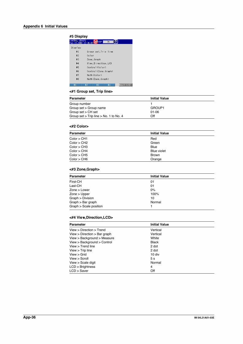
App-36 IM 04L31A01-03E
#5 Display
<#1 Group set, Trip line>
Parameter Initial Value
Group number 1Group set > Group name GROUP1Group set > CH set 01-06Group set > Trip line > No. 1 to No. 4 Off
<#2 Color>
Parameter Initial Value
Color > CH1 RedColor > CH2 GreenColor > CH3 BlueColor > CH4 Blue violetColor > CH5 BrownColor > CH6 Orange
<#3 Zone,Graph>
Parameter Initial Value
First-CH 01Last-CH 01Zone > Lower 0%Zone > Upper 100%Graph > Division 10Graph > Bar graph NormalGraph > Scale position 1
<#4 View,Direction,LCD>
Parameter Initial Value
View > Direction > Trend VerticalView > Direction > Bar graph VerticalView > Background > Measure WhiteView > Background > Control BlackView > Trend line 2 dotView > Trip line 2 dotView > Grid 10 divView > Scroll 5 sView > Scale digit NormalLCD > Brightness 4LCD > Saver Off
Appendix 6 Initial Values

App-37IM 04L31A01-03E
Ap
pen
dix
App
<#5 Control (Color)>
Parameter Initial Value
Select InternalCH101 RedCH102 GreenCH103 BlueCH104 Blue violetCH105 BrownCH106 Orange
<#6 Control (Zone, Graph)>
Parameter Initial Value
First-CH 101Last-CH 101Zone > Lower 0%Zone > Upper 100%Graph > Division 10Graph > Bar graph NormalGraph > Scale position 1
<#7 Math (Color)>
Parameter Initial Value
Select InternalCH31 RedCH32 GreenCH33 BlueCH34 Blue violetCH35 BrownCH36 OrangeCH37 Yellow greenCH38 Light blueCH39 VioletCH40 GrayCH41 LimeCH42 Cyan
<#8 Math (Zone, Graph)>
Parameter Initial Value
First-CH 31Last-CH 31Zone > Lower 0%Zone > Upper 100%Graph > Division 10Graph > Bar graph NormalGraph > Scale position 1
#6 File, DST
Parameter Initial Value
File > Header SpaceFile > Directory name DATA0Daylight saving time (YY/MM/DD HH) > Summer OffDaylight saving time (YY/MM/DD HH) > Winter Off
Appendix 6 Initial Values

App-38 IM 04L31A01-03E
#5 Save/Load,Clear data
Parameter Initial Value
#1 Save settings –#2 Load settings –#3 Save data –#4 Load display data –#5 Load event data –#6 File list –#7 Delete –#8 Format –#9 Clear data –
#8 Time
Parameter Initial Value
Time set –
#9 Math set1 (Expression, Alarm)
Parameter Initial Value
First-CH 31Last-CH 31Math range > Math OffMath Alarm > 1 to 4 Off
#10 Math set2 (Constant)
Parameter Initial Value
Constant > K01 to K12 –
#11 Math set3 (Tag, TLOG, Rolling average, Alarm delay time)
Parameter Initial Value
First-CH 31Last-CH 31Tag > Tag 31TLOG > Timer No. 1TLOG > Sum scale OffRolling average OffAlarm delay time 10 s
Appendix 6 Initial Values

App-39IM 04L31A01-03E
Ap
pen
dix
App
Appendix 7 Control Function Block Diagram
Single Loop Control (Fixed-Point Control)
Input type selection
PVinput
Contact input
DI DI DI
Remoteinput
Unit selection
Analog input range conversion
Square root computation
Input type selection
Unit selection
Analog input range conversion
Square root computation
Ten-segment linearizer approximation/ten-segment linearizer bias
PV input bias
PV input filter
Remote input filter
Ratio bias computation
Control computation section
SP 1 to 8
SP ramp-rate setting
Manual operation
Preset output
Current orpulse
Relay
Run
Auto
LocalRemote
Manual
Stop Stop/Run switching
Manual/Auto switching
Remote/Local switching
Output limiter
DO DO DO DO DO DO
Alarm1 Alarm2 Alarm3 Alarm4 Alarm1 Alarm2
Alarm function
Control output
Note: There are 6 contact input terminals and 6 contact output terminals on a single control output terminal block. The functions that can be assigned to each input/output terminal vary depending on the control mode and whether program operation is enabled.

App-40 IM 04L31A01-03E
Single Loop Control (Program Control)
PVinput
Expansioncontactinput
Control computation section
SP 1 to 8
SP ramp-rate setting
Manual operation
Preset output
Current orpulse
Relay
Run
Auto
Local
Local switching
Program
Program pattern selection
Note: Does not functionduring programcontrol
Program operation
Hold operation startAdvance operation start
Manual
Stop
Control output
Output limiter
Contact input
Timeevent
1
Timeevent
2
Meas.alarm
1
Meas.alarm
2
PV event outputTime event output
Measurement alarm function
DI DI DI DI DIDI
Program
operation stop
Program
operation start
PVevent
1
PVevent
2
DO DO DO DO DO DO
Note: There are 6 contact input terminals and 6 contact output terminals on a single control output terminal block. The functions that can be assigned to each input/output terminal vary depending on the control mode and whether program operation is enabled.
Input type selection
Unit selection
Analog input range conversion
Square root computation
Ten-segment linearizer approximation/ten-segment linearizer bias
PV input bias
PV input filter
Appendix 7 Control Function Block Diagram

App-41IM 04L31A01-03E
Ap
pen
dix
App
Cascade Control (Fixed-Point Control)
Primary loopPV input
Secondary loopPV input
Contact inputRemoteinput
Control computation section 1
SP ramp-rate setting
Secondary loopSP 1 to 8
Primary loopSP 1 to 8
Control computation section 2Manual operation
Preset output
Current orpulse
Relay
Run
Auto, cascade
Auto, manual
MANAUT
LocalRemote
Manual
Stop Stop/Run switching
Manual/Auto, cascade switching
Cascade switchingCascade
Cascade
Tracking signal
Output limiter
Alarm function
Control output
Rem
ote/Local switching
DI DI DI DI DI
DO DO DO DO DO DO
Input type selection
Unit selection
Analog input range conversion
Square root computation
Ten-segment linearizer approximation/ten-segment linearizer bias
PV input bias
PV input filter
Input type selection
Unit selection
Analog input range conversion
Square root computation
Ten-segment linearizer approximation/ten-segment linearizer bias
PV input bias
PV input filter
Input type selection
Unit selection
Analog input range conversion
Square root computation
Alarm1 Alarm2 Alarm3 Alarm4 Alarm1 Alarm2
Note: There are 6 contact input terminals and 6 contact output terminals on a single control output terminal block. The functions that can be assigned to each input/output terminal vary depending on the control mode and whether program operation is enabled.
Remote input filter
Ratio bias computation
Appendix 7 Control Function Block Diagram

App-42 IM 04L31A01-03E
Cascade Control (Program Control)
LocalProgram
Program operation
Hold operation startAdvance operation start
Contact input Contact input
PV event outputTime event output
Measurement alarm function
DI DI DIDI DI DI
Program
operation stop
Program
operation start
Control computation section 1
SP ramp-rate setting
Secondary loopSP 1 to 8
Primary loopSP 1 to 8
Control computation section 2Manual operation
Preset output
Current orpulse
Relay
Run
Auto, cascade
Auto, manual
Manual
Stop Stop/Run switching
Auto/Manual, cascade switching
Cascade switchingCascade
Tracking signal
Output limiter
Control output
Program pattern selection
DO DO DO DO DO DO
Note: Does not functionduring program control
Primary loopPV input
Secondary loopPV input
Input type selection
Unit selection
Analog input range conversion
Square root computation
Ten-segment linearizer approximation/ten-segment linearizer bias
PV input bias
PV input filter
Input type selection
Unit selection
Analog input range conversion
Square root computation
Ten-segment linearizer approximation/ten-segment linearizer bias
PV input bias
PV input filter
Expansioncontact
input
Timeevent
1
Timeevent
2
Meas.alarm
1
Meas.alarm
2
PVevent
1
PVevent
2
Note: There are 6 contact input terminals and 6 contact output terminals on a single control output terminal block. The functions that can be assigned to each input/output terminal vary depending on the control mode and whether program operation is enabled.
Appendix 7 Control Function Block Diagram

App-43IM 04L31A01-03E
Ap
pen
dix
App
Loop Control with PV Switching (Fixed-Point Control)
PVinput
1 Contact input
Loop control with PV switchingPV switching
PVinput
2
Control computation section 2Manual operation
Preset output
Current orpulse
Relay
Run
AutoManual
Stop Stop/Run switching
Manual/Auto switching
Output limiter
DIDIDI
Control output
Remoteinput
Input type selection
Unit selection
Analog input range conversion
Square root computation
SP ramp-rate setting
SP 1 to 8
LocalRemote
Input type selection
Unit selection
Analog input range conversion
Square root computation
Ten-segment linearizer approximation/ten-segment linearizer bias
PV input bias
PV input filter
Input type selection
Unit selection
Analog input range conversion
Square root computation
Ten-segment linearizer approximation/ten-segment linearizer bias
PV input bias
PV input filter
DO DO DO DO DO DO
Alarm1 Alarm2 Alarm3 Alarm4 Alarm1 Alarm2
Alarm function
Note: There are 6 contact input terminals and 6 contact output terminals on a single control output terminal block. The functions that can be assigned to each input/output terminal vary depending on the control mode and whether program operation is enabled.
Remote input filter
Ratio bias computation
Appendix 7 Control Function Block Diagram

App-44 IM 04L31A01-03E
Loop Control with PV Switching (Program Control)
PVinput
1Contact input
Loop control with PV switchingPV switching
PVinput
2
Control computation sectionManual operation
Preset output
Current orpulse
Relay
Run
AutoManual
Stop
Output limiter
DI
DI3
DI DI DI
Control output
SP ramp-rate setting
SP 1 to 8
Local
Local switching
Program
Program pattern selection
Program operation
Hold operation start
Advance operation start
Program operation stop
Program operation start
Note: Does not functionduring programcontrol
Input type selection
Unit selection
Analog input range conversion
Square root computation
Ten-segment linearizer approx.ten-segment linearizer bias
PV input bias
PV input filter
Input type selection
Unit selection
Analog input range conversion
Square root computation
Ten-segment linearizer approx.ten-segment linearizer bias
PV input bias
PV input filter
Expansioncontact
input
Expansioncontact
input
Timeevent
1
Timeevent
2
Meas.alarm
1
Meas.alarm
2
PV event outputTime event output
Measurement alarm function
PVevent
1
PVevent
2
DO DO DO DO DO DO
Note: There are 6 contact input terminals and 6 contact output terminals on a single control output terminal block. The functions that can be assigned to each input/output terminal vary depending on the control mode and whether program operation is enabled.
Analog Retransmission
Contact input
DIAnalog retransmission computatin section
Control measurement data
Manual operation
Current orpulse
Relay
AutoManual
Control output
Appendix 7 Control Function Block Diagram

App-45IM 04L31A01-03E
Ap
pen
dix
App
Appendix 8 Explanation of Engineering Units (EUand EUS)
The CX1000 uses the following two types of engineering units as units for the internal
data.The PV is indicated using the engineering unit of the measurement span (the range usedby control within the PV range).
• EU(): Unit indicating the value using the engineering unit where the low and highlimits of measurement span are EU (0%) and EU (100%), respectively.
• EUS(): Unit indicating the amount of percentage the value occupies against the width
of the measurement span using engineering units.
Below is an example of values converted to EU() and EUS().
If the measurement span is set to –200 to 1200 °C, EU (20%) is 80 °C and EUS (20%) is280 °C.
EU (0%)= –200 °C
EU (20%)= 80 °C
EUS (20%)= 280 °C
EUS (20%)= 280 °C
EUS (100%) = 1400 °C
EU (40%)= 360 °C
EU (100%)= 1200 °C
–200 °C 80 °C 360 °C 1200 °C

App-46 IM 04L31A01-03E
Appendix 9 Program Control Worksheets
Below are conveninent worksheets for setting program control parameters. The excelfile (program_worksheet_e.xls) containing these worksheets is available in the “english”
directory on the accompanying CD-ROM “CX1000/CX2000 Electronic Manual.”
Device Name
Pattern initial setting
Pattern number
Segments
Segment setting method Time , Ramp
Pattern name
Operating loop
Loop 1
Loop 2
Wait action setting
1 2 3 4 5
Loop 1 High
Low
Loop 2 High
Low
Pattern start setting
Start target setpoint Start code
Loop 1 Starting target setpoint start
Loop 2 p PV1 ramp-prioritized sta
p PV2 ramp-prioritized sta
p PV time-prioritized start
Repeat action setting
Repeat frequency
Repeat start segment
Repeat end segment
Wait time

App-47IM 04L31A01-03E
Ap
pen
dix
App
Program pattern and time event setting___1 ___2 ___3 ___4 ___5 ___6 ___7 ___8 ___9 ___0
Ramp/Soak
TSP1
TSP2
Segment time
Ramp-rate time unit
Ramp
PID No.
Shift action
Wait No.
TIM1 ON : : : : : : : : : : : : : : : : : : : :
TIM1 OFF : : : : : : : : : : : : : : : : : : : :
TIM2 ON : : : : : : : : : : : : : : : : : : : :
TIM2 OFF : : : : : : : : : : : : : : : : : : : :
TIM3 ON : : : : : : : : : : : : : : : : : : : :
TIM3 OFF : : : : : : : : : : : : : : : : : : : :
TIM4 ON : : : : : : : : : : : : : : : : : : : :
TIM4 OFF : : : : : : : : : : : : : : : : : : : :
TIM5 ON : : : : : : : : : : : : : : : : : : : :
TIM5 OFF : : : : : : : : : : : : : : : : : : : :
TIM6 ON : : : : : : : : : : : : : : : : : : : :
TIM6 OFF : : : : : : : : : : : : : : : : : : : :
TIM7 ON : : : : : : : : : : : : : : : : : : : :
TIM7 OFF : : : : : : : : : : : : : : : : : : : :
TIM8 ON : : : : : : : : : : : : : : : : : : : :
TIM8 OFF : : : : : : : : : : : : : : : : : : : :
TIM9 ON : : : : : : : : : : : : : : : : : : : :
TIM9 OFF : : : : : : : : : : : : : : : : : : : :
TIM10 ON : : : : : : : : : : : : : : : : : : : :
TIM10 OFF : : : : : : : : : : : : : : : : : : : :
TIM11 ON : : : : : : : : : : : : : : : : : : : :
TIM11 OFF : : : : : : : : : : : : : : : : : : : :
TIM12 ON : : : : : : : : : : : : : : : : : : : :
TIM12 OFF : : : : : : : : : : : : : : : : : : : :
TIM13 ON : : : : : : : : : : : : : : : : : : : :
TIM13 OFF : : : : : : : : : : : : : : : : : : : :
TIM14 ON : : : : : : : : : : : : : : : : : : : :
TIM14 OFF : : : : : : : : : : : : : : : : : : : :
TIM15 ON : : : : : : : : : : : : : : : : : : : :
TIM15 OFF : : : : : : : : : : : : : : : : : : : :
TIM16 ON : : : : : : : : : : : : : : : : : : : :
TIM16 OFF : : : : : : : : : : : : : : : : : : : :
( )
( )
( )
Appendix 9 Program Control Worksheets

App-48 IM 04L31A01-03E
PV event___1 ___2 ___3 ___4 ___5 ___6 ___7 ___8 ___9 ___0
PVE loop number
PVE1 event kind
PVE1 value
PVE2 loop number
PVE2 event kind
PVE2 value
PVE3 loop number
PVE3 event kind
PVE3 value
PVE4 loop number
PVE4 event kind
PVE4 value
PVE5 loop number
PVE5 event kind
PVE5 value
PVE6 loop number
PVE6 event kind
PVE6 value
PVE7 loop number
PVE7 event kind
PVE7 value
PVE8 loop number
PVE8 event kind
PVE8 value
PVE9 loop number
PVE9 event kind
PVE9 value
PVE10 loop number
PVE10 event kind
PVE10 value
PVE11 loop number
PVE11 event kind
PVE11 value
PVE12 loop number
PVE12 event kind
PVE12 value
PVE13 loop number
PVE13 event kind
PVE13 value
PVE14 loop number
PVE14 event kind
PVE14 value
PVE15 loop number
PVE15 event kind
PVE15 value
PVE16 loop number
PVE16 event kind
PVE16 value
PV event hysteresis1 % 9 %
2 % 10 %
3 % 11 %
4 % 12 %
5 % 13 %
6 % 14 %
7 % 15 %
8 % 16 %
Appendix 9 Program Control Worksheets
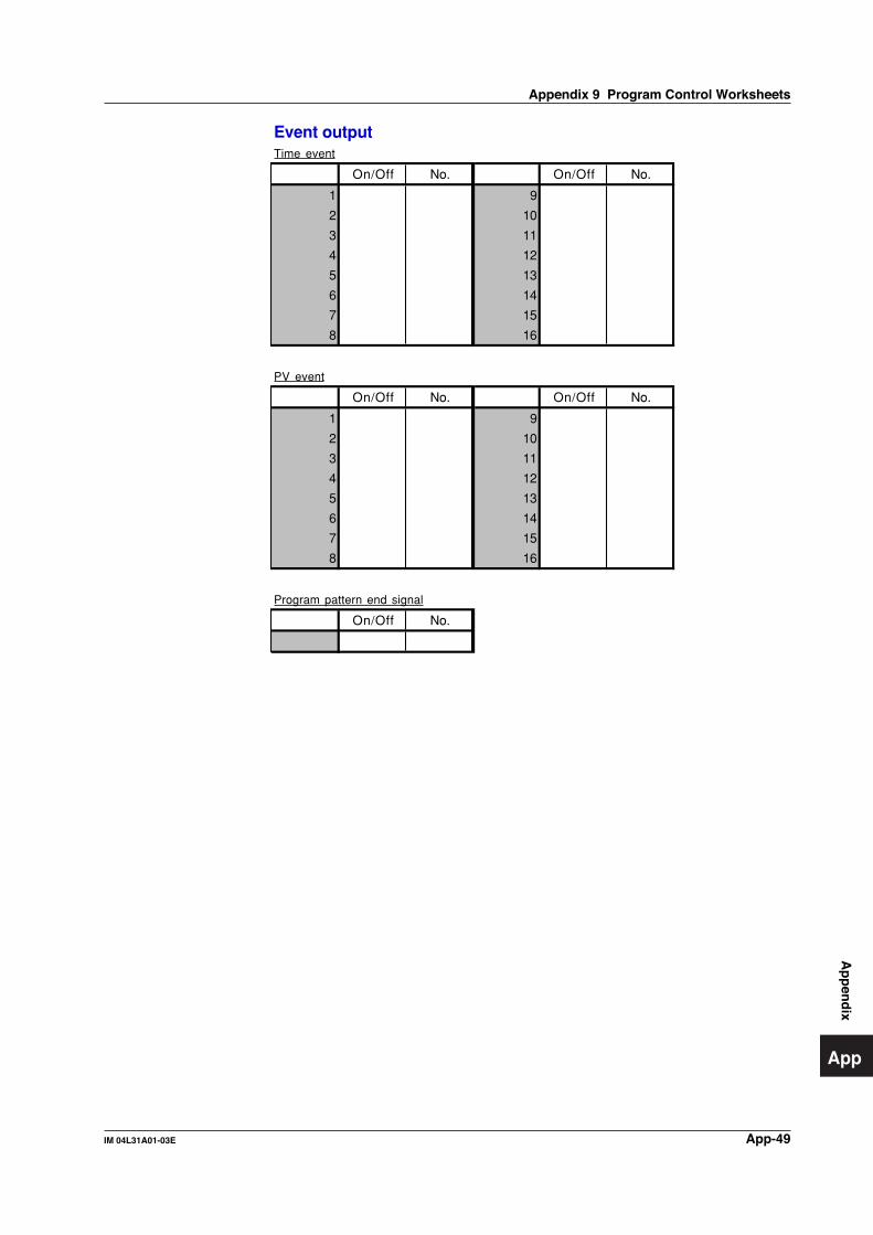
App-49IM 04L31A01-03E
Ap
pen
dix
App
Appendix 9 Program Control Worksheets
Event outputTime event
On/Off No. On/Off No.
1 9
2 10
3 11
4 12
5 13
6 14
7 15
8 16
PV event
On/Off No. On/Off No.
1 9
2 10
3 11
4 12
5 13
6 14
7 15
8 16
Program pattern end signal
On/Off No.

App-50 IM 04L31A01-03E
Appendix 10 Expression Examples
The following are simple application examples using expressions. Refer to them whenusing computation channels.
FunctionThis is a counter that counts from 1 to 15.
Expression31 = 31*(31.LT.K02)+K01K01=1K02=15
ExplanationWhen the value of channel 31 is smaller than 15, the value of (31.LT.K02) is 1. The value of channel 31 increments by 1 every scan interval. When the value of channel 31 is 15, the value of (31.LT.K02) becomes 0. The value of 31*(31.LT.K02)+K01 returns to 1.
Counter
1
15
Scan interval
NoteComputation channels are processed in sequence. The value of the previous scan is used in the computation for its own channel number and channel numbers greater than its own channel number in the expression. In this example, a value one scan behind is used for "31" in "31*(31.LT.K02)+K01."
FunctionIf the measured values on channel 1 are integrated and the total exceeds 1000, 1000 is subtracted from the total, and integration continues.
Scan Interval1 secondChannel 1Measuring range: 0.0–50.0 L/M (liters per minute)
Expression31 =(31+(01/K01))-(31.GE.K02)*K02K01 = 60 (unit of time of the measured flow on channel 1 ÷ scan interval, or in this case, 60 sec. ÷ 1 sec = 60)K02 =1000 (reset if the integrated value exceeds this value)
Explanation(31+(01/K01)) calculates the integrated value on channel 1. When the value of channel 31 is smaller than 1000, the value of (31.GE.K02) is 0. The value of (31.GE.K02)*K02 is 0. When the value of channel 31 is 1000 or higher, the value of (31.GE.K02) is 1. The value of (31.GE.K02)*K02 is 1000. 1000 is subtracted from the integrated value, and integration continues.
Resetting and Carrying Over an Excess When the Integrated Value Exceeds a Certain Value
The portion exceeding 1000 is carried over, and the value is resetChannel 31
1000
Time
Channel 1
(Integration)
Scan interval

App-51IM 04L31A01-03E
Ap
pen
dix
App
FunctionCuts (sets to 0) measured values on channel 1 that are negative or greater than 15, and integrates them.
Expression31 = ((01.GE.K01)AND(01.LE.K02))*0132 = TLOG.SUM(31)K01 = 0K02 =15
ExplanationWhen the value of channel 1 is negative, (01.GE.K01) is 0. When the value of channel 1 exceeds 15, (01.LE.K02) is 0. Therefore, when the value of channel 1 is negative or exceeds 15, the value of channel 31 is 0. Channel 32 integrates the measured value of channel 31.
Applies a Lowcut and Highcut to Measured Values and Integrates Them
Measured value of channel 1
Measured value of channel 31
00
0
0
1
1
15
15
01.GE.K01
01.LE.K02
FunctionAn alarm occurs when the value of channel 1 is 55 or higher. Once the alarm occurs it is not released until the value of channel 1 falls below 50.
Expression31 = (31OR01.GE.K01)AND01.GE.K02K01 = 55K02 = 50Set an upper limit alarm on channel 31 with an alarm value of 1.
ExplanationWhen the value of channel 1 gradually increases to 50 or higher, 01.GE.K02 becomes 1. When the value of channel 1 increases further to 55 or higher, 01.GE.K01 becomes 1. The value of channel 31 becomes 1, and an upper limit alarm occurs on channel 31.
When the value of channel 31 is 1, it remains at that value even if the value of channel 1 falls in the range from 50 to 55. If the value of channel 1 decreases further to below 50, the value of channel 31 becomes 0. The upper limit alarm on channel 31 is released.
Setting a Margin around the Value Measured upon Occurrence and Release of Alarms (Alarm Hysteresis)
Measured value of channel 1
Measured value of channel 31
5550
0
0
1
01
1
Alarm occurrenceAlarm release
01.GE.K02
01.LE.K01
Appendix 10 Expression Examples

App-52 IM 04L31A01-03E
FunctionAverages the measured values on channel 1 every 5 minutes and displays the result.
Scan Interval1 second
Expression
31 = 31*(31.LT.K02)+K01
32 = 32*(31.NE.K01)+01
33 = 32/31
34 = (33*(31.EQ.K02))+(34*(31.NE.K02))
K01 = 1
K02 = 300
ExplanationChannel 31 is a counter that increments by 1 every scan interval. It counts from 1 to 300, and then repeats. Channel 32 integrates the measured values on channel 1 until channel 31 reaches 300. Channel 33 calculates the average value of channel 1. Channel 34 displays the value of channel 33 when channel 31 is 300, and holds that value until the next time channel 31 becomes 300.
Displaying the Average Value
Channel 31 (counter)
Channel 32 (integrated value)
Channel 33 (average value)
Channel 34 (average every 5 min.)
0300
Time
5 minutes
Appendix 10 Expression Examples

Index-1IM 04L31A01-03E
Ind
ex
Index
Index
block display ..................................................................... 1-70boundary ........................................................................... 8-22brightness of display ......................................................... 3-13burnout .................................................... 1-24, 1-59, 4-4, 7-2
Ccalculation expression ....................................................... 10-3calibration .......................................................................... 13-2CAS ..................................................................................... 6-2cascade control ................................................. 1-3, 1-18, 4-2channel ........................................................................... 10-13channel, assignment of ....................................................... 8-3channel display color ........................................................ 8-14characters, entry of ............................................................. 3-9clearing of the memory ..................................................... 3-14CLOG ................................................................................ 1-95CLOG computation ...................................................... App-15CLOG error ....................................................................... 4-12color ........................................................................ 8-13, 8-15comment ......................................................................... 11-17communication command log ........................................... 11-9computation .................................................................... 11-12computation error ...................................................... 1-8, 4-43computation function ............................................ 1-91, App-6computation icon ............................................................... 1-70computation, starting/stopping/resetting of ....................... 10-4conditional expression ................................................. App-16constant ............................................................................ 10-3contact input (DIGITAL IN/REMOTE) wiring ..................... 2-15contact input, registration of ................................................ 4-7contact input/output ........................................................... 1-25contact output (DIGITAL OUT) wiring ............................... 2-16contact output (LOOP1 to 6) wiring ................................... 2-15control action summary display ......................................... 1-74control constant ....................................................... 4-47, 4-48control data ....................................................................... 1-86control direction ....................................................... 1-33, 4-28control function block diagram ..................................... App-39control group ..................................................................... 1-71control group display ....................................... 1-14, 1-71, 6-1control mode ............................................................. 1-17, 4-2control operation mode ....................................................... 1-6control output, changing of .................................................. 6-3control output limiter .......................................................... 1-32control output suppressing function .................................. 4-26control output suppression ................................................ 1-35control output terminal block ............................................... 2-6control output type ............................................................ 4-14control output wiring .......................................................... 2-15control parameter ................................................................ 1-4control period .................................................................... 1-16controller style ................................................................... 1-14current output .................................................................... 4-14cursor, turning off ................................................................ 8-8cycle time .......................................................................... 4-14
DD ................................................................... 1-32, 4-28, 6-10data acquisition to the internal memory ....... 1-86, 9-2, App-1data length .......................................................................... 9-4data, saving of ................................................................... 1-88
AA/D converter, integration time of ..................................... 1-58A1 ...................................................................................... 6-10A2 ...................................................................................... 6-10A3 ...................................................................................... 6-10A4 ...................................................................................... 6-10access lamp ........................................................................ 3-2accessories, optional ............................................................. vaccessories, standard ............................................................ vaction .................................................. 4-24, 7-9, 10-9, 11-12ADVANCE ......................................................................... 6-17advance ............................................................................ 6-22alarm ............................................. 1-38, 1-39, 1-61, 2-7, 8-1alarm control ....................................................................... 8-1alarm delay ............................................................... 7-9, 10-7alarm hysteresis ...................................................... 1-39, 1-63alarm icon ......................................................................... 1-70alarm indication ....................................................... 1-65, 1-83alarm mode ............................................................. 1-38, 4-12alarm On/Off ..................................................................... 4-24alarm operating conditions ................................................ 1-38alarm output ........................................................................ 1-5alarm relay output ............................................................. 1-63alarm standby ........................................................... 1-5, 1-39alarm summary ................................................................. 1-79alarm type ......................................................................... 1-38alarm value ........................................... 1-39, 4-24, 7-8, 10-6AlarmACK ..................................................... 4-23, 7-7, 11-12all channel display ....................................................... 8-7, 8-9analog control input terminal block ..................................... 2-5analog input for loop control ................................................ 1-2analog output, selection of ................................................ 1-20analog retransmission ............................................. 1-95, 4-41Analog-output type ............................................................ 4-14AND .................................................................................... 7-9AND/OR ............................................................................ 1-64anti-reset windup ............................................................... 1-35application name ............................................................. 11-16ASCII file ...................................................................... App-20AT ..................................................................................... 6-10ATA flash memory card .................................................... 3-17AUT ..................................................................................... 6-2auto increment ................................................................ 11-16auto logout ........................................................................ 11-6auto message for program run/reset ................................. 5-14auto operation ..................................................................... 1-6auto save .......................................................................... 1-88auto save interval ................................................................ 9-5auto tuning ........................................................ 1-55, 4-2, 6-8auto/manual/cascade, switching between .......................... 6-2
Bbackground color .............................................................. 8-24backlight saver ........................................................ 1-85, 3-13bar graph ........................................................................... 8-18bar graph display .............................................................. 1-78basic setting mode .................................................... 1-12, 3-4batch header ....................................................... 1-101, 11-14batch number ...................................................... 11-16, 11-17bias ......................................................................... 1-22, 4-22block .................................................................................... 9-3

Index-2 IM 04L31A01-03E
data type ............................................................................. 9-3day/day of the week ................................................ 9-5, 10-13DB ..................................................................................... 6-10de-energize ....................................................................... 1-64Decrease ........................................................................... 7-10DELAY .............................................................................. 6-16delay lower limit alarm ...................................................... 1-62delay time .......................................................................... 6-12delay time for starting the program pattern contro ............ 6-19DELAY TM ........................................................................ 6-14delay upper limit alarm ...................................................... 1-61derivative time ......................................................... 1-32, 4-28detection ................................................................... 7-9, 10-7deviation high & low limit ................................................... 1-38deviation high-limit ............................................................ 1-38deviation low-limit .............................................................. 1-38deviation within high & low limits ....................................... 1-38DI/DO label ....................................................................... 4-40DI/DO status display ......................................................... 1-73difference lower limit alarm ............................................... 1-61difference upper limit alarm ............................................... 1-61digital display .................................................................... 1-77DIGITAL IN ..................................................... 2-6, 2-15, 2-16DIGITAL OUT ........................................................... 2-6, 2-16DIO operation control ........................................................ 1-28DIO operation monitoring .................................................... 1-9DIO operation monitoring function .................................... 4-37DIO type ............................................................................ 4-38direct control ..................................................................... 1-33directory name .................................................................... 9-6display color ...................................................................... 8-14display data ............................................................. 1-86, 1-88display data, loading of ..................................................... 9-10display direction ................................................................ 8-24display update rate ............................................................ 8-10displays, switching of ................................................ 1-12, 3-5divisions, number of .......................................................... 8-18DO ....................................................................................... 2-6DR ..................................................................................... 6-10DSP LOOP ........................................................................ 6-14
Ee-mail transmission function icon ...................................... 1-70e-mail transmission log ..................................................... 11-9edit segment number .......................................................... 5-3end segment number ........................................................ 5-11energize ............................................................................ 1-64engineering unit ........................................................... App-45Enter setup ........................................................................ 11-7equation ............................................................. 10-3, App-11error message log ............................................................. 11-8error messages ................................................................. 12-1ESC key .............................................................................. 3-2EU ................................................................................ App-45EUS .............................................................................. App-45EV KIND ............................................................................ 6-15EV ON/OFF ....................................................................... 6-15event ........................................................................... 5-8, 9-3event data ............................................................... 1-86, 1-89event data, loading of ........................................................ 9-10event display ..................................................................... 6-15event group ....................................................................... 5-16event output ............................................................ 1-27, 5-14executing several program pattern ................................... 6-18Expand .............................................................................. 8-22external storage medium .................................................. 3-17external storage medium drive ............................................ 3-2
external storage medium, formatting of .................. 3-19, 9-13external storage medium icon ........................................... 1-70
Ffaceplate style ................................................................... 1-14FAIL output ................................... 1-5, 1-27, 1-99, 2-7, 4-16file ....................................................................................... 9-6file format .......................................................................... 9-14file management on the external storage medium ............ 9-11file name ................................................................. 1-90, 9-14filter ................................................................................... 4-22fixed-point control ................................................................ 1-3floppy disk ......................................................................... 3-17format ...................................................................... 3-19, 9-13front panel ........................................................................... 3-1FTP file transfer log ........................................................... 11-9FUNC key ........................................................................... 3-2FUNC key operation ........................................................... 3-6functional ground terminal ...................................................... ii
Ggraph ................................................................................. 8-18grid .................................................................................... 8-24group ................................................................................. 1-71group name ............................................................... 4-29, 8-3Group NO. ......................................................................... 6-10group number ............................................................ 4-29, 8-3
HH ....................................................................................... 6-10header ................................................................................. 9-6high-limit alarm .................................................................. 1-61historical trend display .................................... 1-81, 8-9, 9-10historical trend, switching to ................................................ 8-1HOLD ................................................................................ 6-17hold ................................................................................... 1-65hold operation ................................................................... 6-21hold operation mode ......................................................... 6-19hybrid style ........................................................................ 1-14hysteresis ...................................................... 1-37, 4-35, 7-10
II ..................................................................... 1-32, 4-28, 6-10image data ........................................................................ 1-89Increase ............................................................................ 7-10indicator, hold .................................................................... 7-10information display, switching of ......................................... 8-1initial PID ................................................................... 1-17, 4-2initial values ................................................................. App-24initialization ....................................................................... 3-14input filter .......................................................................... 1-21input range ........................................................................ 1-21input switching condition ................................................... 1-18input type ............................................ 1-21, 1-58, 4-20, 4-32installation location .............................................................. 2-2installation procedure .......................................................... 2-3integral time .......................................... 1-32, 1-58, 4-28, 7-2internal switch ..................................................................... 1-8interval .............................................................................. 10-9Item name ......................................................................... 4-18
Index

Index-3IM 04L31A01-03E
Ind
ex
Index
Kkey lock ................................................................... 1-96, 11-3Key lock icon ..................................................................... 1-70kind ................................................................................... 4-30
Llanguage, changing of ....................................................... 3-15local ..................................................................................... 1-6local operation mode ......................................................... 6-19log display ......................................... 1-97, 11-8, 11-9, 11-10logic computation .................................................... 1-95, 4-45login/logout ........................................................................ 11-5login/logout log .................................................................. 11-8logout ................................................................................ 1-97loop ..................................................................................... 5-8loop control with PV switching .................................. 1-3, 1-18loop number ........................................................................ 4-2lot number ........................................................... 11-16, 11-17low-cut ............................................................................... 4-22low-signal cutoff point ....................................................... 1-23lower limit alarm ................................................................ 1-61lower limit on rate-of-change alarm ................................... 1-61
MMAN .................................................................................... 6-2manager name ................................................................ 11-16manual operation ................................................................ 1-6manual reset ........................................................... 1-33, 4-28manual sample ................................................................ 11-13manual sampled data .............................................. 1-87, 1-89manual save ...................................................................... 1-88manual tuning ........................................................... 1-54, 6-8math On/Off ...................................................................... 10-3math reset ....................................................................... 11-12measured data, clearing of ............................................... 9-15measurement alarm .......................................................... 1-61measurement alarm option terminal block .......................... 2-7measurement group .................................................. 1-71, 8-2measurement input terminal block ...................................... 2-8measurement input wiring ................................................. 2-14measurement span ........................................................... 1-21media ................................................................................ 3-17media save .......................................................................... 9-3MEMORY ............................................................................ 2-7memory ............................................................................. 1-86memory, clearing of .......................................................... 3-14memory end output ........................................................... 1-99memory information, displaying of ...................................... 8-9memory summary ............................................................. 1-80MENU key ........................................................................... 3-2message ........................................... 1-75, 8-11, 11-13, 12-1message summary ............................................................ 1-80Mode ................................................................................... 6-2mode ................................... 1-21, 1-58, 4-20, 7-3, 9-3, 10-9MODEL ................................................................................. ivmodule ................................................................................ 4-7moving average ........................................................ 1-60, 7-5MR .................................................................................... 6-10
Nnonhold ............................................................................. 1-65number .................................................. 4-30, 7-9, 10-7, 11-7
OOH ..................................................................................... 6-10OL ..................................................................................... 6-10on-time/off-time ................................................................... 5-9ON/OFF control ....................................................... 1-37, 4-14operation mode ......................................................... 3-4, 6-19operation mode during program control ............................ 6-19operation status indication section .................................... 1-67OUT ............................................................................ 1-2, 6-3output high-limit ................................................................. 1-38output low-limit .................................................................. 1-38Output lower/upper limit .................................................... 4-28output upper/lower limit ..................................................... 1-32output velocity limiter ........................................................ 1-36over-integration prevention ............................................... 1-35overshoot suppression ...................................................... 1-35overview display ...................................... 1-72, 1-79, 6-7, 8-8overview display, switching of ............................................. 6-7
PP .................................................................... 1-32, 4-28, 6-10Panel1Load to Panel3Load ............................................. 11-13partial expanded display ......................................... 1-77, 8-22parts replacement ............................................................. 13-4password ................................................................. 11-4, 11-7pattern name ....................................................................... 5-3pattern number .............. 5-3, 5-5, 5-6, 5-8, 5-11, 6-12, 6-16periodic inspection ............................................................ 13-1PID constant ..................................................................... 1-32PID control mode ........................................................ 1-3, 4-2PID group number ..................................................... 1-16, 4-1PID, initial value ........................................................ 1-17, 4-2PID number ............................................................. 1-31, 4-28PID selection method ................................................ 1-4, 1-16PO ..................................................................................... 6-10power supply, wiring of ..................................................... 2-17pre-trigger ........................................................................... 9-4preset output ........................................................... 1-34, 4-28program control ......................................................... 1-10, 4-2program control mode ....................................................... 6-19program control, starting ................................................... 6-19program display position ................................................... 5-14program pattern name ............................................ 6-12, 6-16program pattern start segment, selection of ..................... 6-19program selection display ................................................. 6-12proportional band .................................................... 1-32, 4-28PT NO. .............................................................................. 6-13PV ....................................................................... 1-2, 1-3, 2-5PV event ............................................................................. 5-8PV event hysteresis .......................................................... 5-10PV high-limit ...................................................................... 1-38PV low-limit ....................................................................... 1-38PV range conversion ......................................................... 1-23PV range lower/upper limit ................................................ 4-21PV switching lower/upper limit .......................................... 4-21PV tracking ........................................................................ 1-24PV/SP computation ................................................. 1-95, 4-41PV/SP computation function ............................................. 4-12
RR/D .................................................................................... 4-28ramp .................................................................................... 5-7ramp-rate time unit .................................................... 4-26, 5-7ramp/soak select ................................................................. 5-6range ..................................................... 1-21, 1-59, 4-20, 7-3
Index

Index-4 IM 04L31A01-03E
rate-of-change alarm ......................................................... 7-10ratio setting ....................................................................... 4-22rear panel ............................................................................ 3-3reference deviation ................................................. 1-32, 4-26reference point .............................................. 1-17, 1-31, 4-26reference time ................................................................... 10-9reflash alarm ....................................................................... 7-9relay .................................................................................... 7-9relay action/behavior ......................................................... 4-16relay contact output ........................................................... 4-14relay hold .......................................................................... 7-10relay hysteresis ................................................................. 1-37relay hysteresis value and activation point ....................... 4-28relay output ............................................................... 7-8, 10-6relay output/number .......................................................... 4-24REM/LOC ............................................................................ 6-3remaining segment time .................................................... 6-17REMOTE ................................................................... 2-7, 2-15remote ......................................................................... 1-6, 4-5remote input .............. 1-6, 1-27, 1-100, 11-11, 11-12, 11-13remote setting ................................................................... 4-12Remote/Local, switching between ...................................... 6-3repeat ...................................................................... 6-12, 6-16repeat frequency ............................................................... 5-11replacement period ........................................................... 13-4report channel ................................................................. 10-13report data ..................................................... 1-81, 1-87, 1-89report function .................................................... 1-92, App-17report function, starting/stopping of ................................. 10-14report types ..................................................................... 10-13RESET .............................................................................. 6-16reset ........................................................................ 4-28, 10-9reset mode ........................................................................ 6-19restart mode .............................................................. 1-17, 4-2reverse control .................................................................. 1-33RJC ......................................................... 1-24, 1-59, 4-5, 7-2RSP ............................................................................. 1-2, 2-5RSP input .................................................................. 1-6, 1-30RSP input selection ........................................................... 4-12RST ................................................................................... 6-16RUN .................................................................................. 6-16run/auto/cascade, switching between ................................. 6-2RUN/RST .......................................................................... 6-16run/stop operation ....................................................... 1-6, 6-1RUN/STP ............................................................................ 6-2
Ssample rate ......................................................................... 9-3samples, number of ........................................................ 10-11sampling interval ............................................................. 10-11save .................................................................................. 1-88save data ............................................................................ 9-6scale .......................................................................... 4-21, 7-4scale display ON/OFF ......................................................... 8-7scale lower/upper limit ...................................................... 4-21scale, number of digits displayed ...................................... 8-20scale position .................................................................... 8-19scan interval .............................................................. 1-58, 7-2screen image data, saving of ............................................ 9-14scroll .................................................................................. 8-24SEG TIME ......................................................................... 6-17segment edit ....................................................................... 5-3SEGMENT NO .................................................................. 6-13segment number ..................................... 5-6, 5-8, 6-12, 6-16segment PID group No. ...................................................... 5-7
segment setting method ...................................................... 5-3SEGMENT TIME ............................................................... 6-13segment time .................................................. 5-7, 6-12, 6-16segments ............................................................................ 5-3self diagnosis .................................................................... 4-16self diagnosis output ................................................. 1-5, 1-27setpoint limiter ................................................................... 1-30settings, initialization of ..................................................... 3-14setup data ......................................................................... 1-90setup data, loading and saving of ....................................... 9-9setup mode ......................................................................... 3-4shunt resistor ............................................................ 4-21, 7-3shutdown function ................................................... 1-33, 4-28single-loop control ............................................. 1-3, 1-17, 4-2snapshot ......................................................................... 11-13soft keys .............................................................................. 3-2SP ............................... 1-2, 1-3, 1-29, 1-37, 4-28, 6-2, 6-10SP, changing of ................................................................... 6-2SP high-limit ...................................................................... 1-38SP low-limit ....................................................................... 1-38SP NO. .............................................................................. 6-10SP number ........................................................................ 4-24SP number selection source ............................................. 4-12SP ramp-down-rate/SP ramp-up-rate ..................... 1-30, 4-26span ...................................................... 1-21, 1-59, 4-20, 7-3span upper/lower limit ....................................................... 10-3split window display .......................................................... 6-20square-root computation ......................................... 1-23, 4-22ST SEG ............................................................................. 6-14standard PID control ........................................................... 1-3standard signal .................................................................. 1-21standby ............................................................................. 4-24start code ............................................................................ 5-5start segment number ............................................. 5-11, 6-12start/stop ......................................................................... 11-12START/STOP key ....................................................... 3-2, 3-7storage function ................................................................ 1-86style number ........................................................................... iSUFFIX ................................................................................. ivsum scale ............................................................ 10-10, 10-13supervisor name ............................................................. 11-16switching condition .................................................... 1-18, 4-2switching hysteresis ................................................ 1-31, 4-26switching pattern number .................................................. 6-18system information display .................................... 1-98, 11-10
Ttag/channel ......................................................................... 8-5tag/tag comment ............................................................... 4-26tags ................................................................. 1-71, 8-5, 10-3target setpoint ........................................................... 5-7, 6-17target setpoint selection method ..................... 1-4, 1-16, 1-31target setpoint tracking ...................................................... 1-29ten-segment linearizer approximation ............................... 1-22ten-segment linearizer biasing .......................................... 1-22ten-segment linearizer I/O ................................................. 4-32ten-segment linearizer mode ............................................ 4-32time ......................................................................... 9-5, 10-13time adjustment ............................................................... 11-12time event ........................................................................... 5-8time, setting of ................................................................... 3-11time zone, changing of ...................................................... 3-16timer number ................................................................... 10-10timeup type ......................................................................... 9-5
Index

Index-5IM 04L31A01-03E
Ind
ex
Index
TLOG .............................................................................. 10-10TLOG data ........................................................................ 1-89trend display ...................................................................... 1-75trend line width .................................................................. 8-24trigger ...................................................................... 9-4, 11-12trip line .............................................................................. 8-13trip line width ..................................................................... 8-24troubleshooting ............................................................... 12-11TSP CHG .......................................................................... 6-17TUNING .............................................................................. 6-4tuning ...................................................................... 1-54, 1-55tuning display .................................................................... 1-72tuning display, switching to ................................................. 6-4tuning operation .................................................................. 6-8tuning parameters ON/OFF .............................................. 4-18type ................. 1-21, 1-58, 4-20, 4-24, 5-9, 7-8, 9-13, 10-6
Uunit ................................................................ 1-21, 4-22, 10-3upper limit on rate-of-change alarm .................................. 1-61user ID .............................................................................. 11-7USER key ......................................................... 1-96, 3-2, 3-7USER key assignment ...................................................... 11-1user name ......................................................................... 11-7
Vvalue, entry of ..................................................................... 3-9voltage pulse output .......................................................... 4-14
WWAIT ................................................................................. 6-16wait ...................................................................................... 5-7wait operation .................................................................... 6-21wait time .............................................................................. 5-4wait zone ............................................................................. 5-4wait zone number ................................................................ 5-7Web browser operation log ............................................... 11-9
ZZip disk .............................................................................. 3-17zone display ...................................................................... 1-76zone lower/upper limit ....................................................... 8-16zone PID method ............................................ 1-4, 1-17, 1-31zone PID selection .................................................... 1-16, 4-2zooming in on the time axis ................................................ 8-9
Index


