Transportation and Supply of Liquified Natural Gas Through ...
DatasheetApril 2013
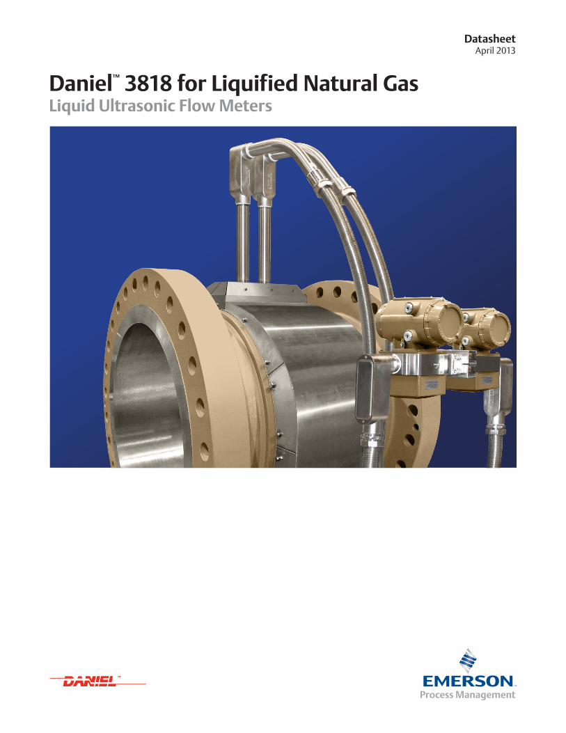
Daniel™ 3818 for Liquified Natural GasLiquid Ultrasonic Flow Meters


www.EmersonProcess.com 1
DatasheetLiquid Ultrasonic Flow Meter
OverviewThe Daniel 3818 Liquid Ultrasonic Flow Meter is designed for high accuracy and long-term, reliable performance in LNG applications. The 3818 features a unique multi-plane interlocked 8-path British Gas design.
The equivalent of two 4-path meters in a single body, the completely redundant design utilizes two independent transmitters—one for each set of four (4) chordal paths and offers the ability to poll each 4-path meter separately. Acoustic processing is performed by specialized electronics designed to achieve high sampling rates, provide stable ultrasonic signals and optimal low flow response delivering accurate, stable and reliable measurement.
Ideal for meeting strict safety and environmental regulations, the 3818 LNG meter was engineered, designed and manufactured to Daniel's ISO certifications (9001, 14001). Additionally, the meter comes equipped with advanced diagnostics software, which allows operators to learn more about system performance and monitor the meter's health. Meters are calibrated using both a static zero flow test on liquid nitrogen and a full dynamic test on water in our ISO 17025 certified flow calibration facility.
Available in nominal line sizes 8” to 36”, the 3818 LNG meter offers increased flow capacity and no incremental pressure drop, therefore minimizing operating costs and improving measurement integrity and safety.
Figure 1: Daniel 3818 Liquid Ultrasonic Flow Meter for Liquefied Natural Gas Applications
LNG Applications � Custody Transfer
� Tanker Loading and Off-Loading
� Liquefaction Trains (Rundown Lines)
� Storage Allocation
� Check Metering
� Line Balance
Features and Benefits � Redundant 4-path chordal design ensures accuracy,
stability and operational cost savings
� Ease of installation and operation reduces start-up time and lowers capital costs
� Full bore design eliminates incremental pressure drop, improving measurement and reducing energy costs
� Geometric correction calculations account for meter body expansion/contraction due to changes in pressure and temperature
� Meter factory insulation minimizes heat sinks and hot spots and reduces startup time
� Equipped with MeterLinkTM advanced diagnostics software for monitoring meter and system performance
� 3810 Series Electronics provide fast sampling rates, enabling quick response to process upsets
� Communicates predictive diagnostics and processes variable information via the HART® protocol which allows plant personnel to quickly detect and respond to abnormal situations, avoiding process upsets and unscheduled downtime
� The 3818 is part of Emerson's broad range of intelligent field devices that power the PlantWeb
® digital plant architecture
Redundancy for High Accuracy and Long-Term Stability

www.EmersonProcess.com 2
April 2013Daniel 3818
Meter SpecificationsCharacteristics
� Eight-path (sixteen transducer) chordal design
� British Gas (BG) configuration
� Two paths are paired at each of the four horizontal chords in the pipe cross section. The paired paths are angled with respect to the pipe axis such that four horizontal chords lie in each of the angled planes, forming an X when viewed from above. This allows a true 3-D representation of the flow profile.
Meter Performance
� Factory proven linearity is ± 0.15% of measured value over a 1.2 to 12.2 m/s (4 to 40 ft/s) range
� Factory proven linearity is ± 0.20% of measured value over a 0.6 to 12.2 m/s (2 to 40 ft/s) range (option)
Uncertainty of Meter Factor
� < ± 0.027% (API MPMS, chapter 5, section 8, table B-1)
Velocity Range
� 0.6 to 12.2 m/s (2 to 40 ft/s) with an over-range of 0.3 to 14.6 m/s (1 to 48 ft/s)
Calibration
� ISO 17025 certified flow laboratory available for all meters
Electronics PerformancePower (Each set of electronics)
� 10.4 VDC to 36 VDC
� 8 watts typical
� 15 watts maximum
(1) Please consult Daniel if your requirements are outside the list specifications. Improved performance, other product and material offerings may be available
depending on the application.
(2) Consult factory on sizes above 900 mm (36").
Standard Specifications(1)
Meter Mechanical Ratings Line Sizes
� 200 mm to 900 mm (8" to 36")(2)
Operating Product Temperature
� -196°C to +60°C (-385°F to +140°F)
Operating Pressure Range
� 0 to 250 Bar (0 to 3600 psig)
Specific Gravity Range
� 0.35 and higher (nominal 0.45)
Flanges
� Raised Face for ANSI Classes 150 to 1500
Electronics Ratings Remote Mounted Electronics
� 2.1 m (7ft) cable included
� Ambient Temperature
� -40°C to +60°C (-40°F to +140°F)
� Relative Humidity
� Up to 95% non-condensing
Storage Temperature
� -50°C to +60°C (-40°F to +140°F)

www.EmersonProcess.com 3
DatasheetLiquid Ultrasonic Flow Meter
(1) Please consult Daniel if your requirements are outside the list specifications. Improved performance and other product and material offerings may be available.
(2) Pressure rating information is for -385°F (-196°C) to 140°F (60°C).
Materials of Construction(1)
Material Specifications
Body and FlangeForgings
� ASTM A182 dual grade F316/F316L SST -196°C to +60°C (-385°F to +140°F)
Electronic Enclosures � ASTM A351 Gr CF8M stainless steel
Transducer Components Transducer Housing
� Full penetration weld for pressure containment
Transducer Housing Materials
� ASTM A479 316L stainless steel with proprietary matching layer material
Insulation Package Shroud Material
� ASTM A240 316 stainless steel
Factory Insulation
� Insulation is positioned around all transducers and meter body reducing likelihood of hot spots
� Reduces installation and start-up time in the field
Paint Specifications
Body and FlangeStainless Steel
� Unpainted
� Consult factory for painted stainless steel specification
Electronic EnclosuresStainless Steel
� Unpainted
� Consult factory for painted stainless steel specification
Table 1A: Body and Flange Maximum Pressure Ratings by Construction Materials - bar(2)
[Meter Sizes 200 to 900 mm]
PN F316/F316L SST
20 19.0
50 49.6
100 99.3
150 148.9
250 248.2
Table 1B: Body and Flange Maximum Pressure Ratings by Construction Materials - psi(2)
[Meter Sizes 8” to 36”]
ANSI F316/F316L SST
150 275
300 720
600 1440
900 2160
1500 3600

www.EmersonProcess.com 4
April 2013Daniel 3818
Table 2A: Daniel 3818 Flow Range Table - Metric Units
Nominal Meter Size (mm) Meter I.D. (mm) Pipe ScheduleFluid Velocity (m/s) Flow Rate (m3/hr)
Min Max Over-Range Min Max Over-Range
200 202.72 Sch 40 0.61 12.2 14.6 71 1,417 1,700
250 254.51 Sch 40 0.61 12.2 14.6 112 2,233 2,679
300 303.23 Sch 40 0.61 12.2 14.6 158 3,170 3,803
400 381.00 Sch 40 0.61 12.2 14.6 250 5,004 6,005
450 428.65 Sch 40 0.61 12.2 14.6 317 6,334 7,601
500 477.82 Sch 40 0.61 12.2 14.6 394 7,871 9,445
600 574.65 Sch 40 0.61 12.2 14.6 569 11,383 13,660
750 742.95 STD 0.61 12.2 14.6 951 19,028 22,833
900 895.35 STD 0.61 12.2 14.6 1,382 27,635 33,162
Table 2B: Daniel 3818 Flow Range Table - English Units
Nominal Meter
Size (in)
Meter I.D.
(in)
Pipe
Schedule
Fluid Velocity (ft/s) Flow rate (BPH) Flow Rate (GPM)
Min Max Over-Range Min Max Over-Range Min Max Over-Range
8 7.981 Sch 40 2 40 48 446 8,910 10,692 312 6,237 7,485
10 10.020 Sch 40 2 40 48 702 14,045 16,853 492 9,831 11,797
12 11.938 Sch 40 2 40 48 997 19,936 23,923 698 13,955 16,746
16 15.000 Sch 40 2 40 48 1,574 31,474 37,769 1,102 22,032 26,438
18 16.876 Sch 40 2 40 48 1,992 39,839 47,807 1,394 27,887 33,465
20 18.812 Sch 40 2 40 48 2,475 49,504 59,405 1,733 34,653 41,583
24 22.624 Sch 40 2 40 48 3,580 71,599 85,919 2,506 50,120 60,144
30 29.25 STD 2 40 48 5,984 119,680 143,617 4,189 83,776 100,531
36 35.25 STD 2 40 48 8,691 173,816 208,580 6,084 121,671 146,005
Standard Flow Ranges

www.EmersonProcess.com 5
DatasheetLiquid Ultrasonic Flow Meter
(1) The analog-to-digital conversion accuracy is within ±0.05% of full scale over the operating temperature range.
(2) AI-1 and AI-2 are electronically isolated and operate in sink mode. The input contains a series resistance so HART® Communicators can be connected to configure sensors.
(3) A 24 Volt DC power supply is available to provide power to the sensors.
(4) The analog output zero scale offset error is within ±0.1% of full scale and gain error is within ±0.2% of full scale. The total output drift is within ±50 ppm of full scale per °C.
Input/Output
The Daniel 3818 LNG Ultrasonic Flow Meters provide the following I/O connections on the CPU Module. Each meter has two sets of electronics with independent transmitters—one for each set of four (4) chordal paths.
Communications Specifications
Communication Protocols (1) Serial RS-232/RS-485 port (115 kbps baud rate) RS-232/RS-485 Full Duplex/RS-485 Half Duplex
� Modbus RTU/ASCII
(1) Ethernet Port (TCP/IP) 100 BaseT � Modbus TCP
Digital, Analog and Frequency Inputs
Digital Input(1) (1) Single polarity (Contact closure)
� Status
Analog Inputs(3) (2) 4-20 mA � AI-1 Temperature(2)
� AI-2 Pressure (2)
Digital, Analog and Frequency Outputs
Frequency/Digital Outputs (3) Frequency/Digital Outputs � User Configurable TTL/Open Collector
Analog Outputs(3)(4) (2) 4-20 mA � Independently configurable analog outputs
� HART 7 Compliant, consult factory for HART 5

www.EmersonProcess.com 6
April 2013Daniel 3818
Meter Software
MeterLink™ OverviewDaniel’s MeterLink™ software gives users access to information not seen before. This information is presented in an intuitive graphical format that takes complexity out of your flow measurement.
This critical information will empower your staff to work predictively, instead of reactively.
� MeterLink™ software is supplied with meter at no charge
� MeterLink™ is required for transmitter configuration
� MeterLink™ software requires RS-232, RS-485 full duplex, or Ethernet (recommended)
� Supports Windows™ XP, 7 and 8, as well as Microsoft® Office® Excel® 2000 or later
The 3818 is also configurable with AMS™ Device Manager or 375 / 475 Field Communicator via HART®
Table 3: Daniel MeterLink™ Features
Pow
erfu
l An
alys
is
� View, analyze and save waveforms
� Daily and hourly Logs alarms and audit history retrieval in Excel® or CSV files
� Daily and hourly log graphing
� Reverse flow alert display
� Alarms listed primary cause first
� Separate latched alarm display
� Trend maintenance logs
� Compare meter configurations saved in Excel® logs
� Calibrate analog inputs
Intu
itiv
e In
terf
ace
� Summarized and detailed views for meter performance information
� Built-in maintenance logs and inspection reports
� Meter directory support
� View multiple graphs simultaneously
� Automatic file naming and organized saving, supports hundreds of meters
Qu
ick
Star
t-u
p
� Easy upgrade of meter firmware
� Modbus and HART configuration
� Zero calibration wizard
� Field setup wizard
� Flow calibration wizard and meter factor adjustment
Ver
sati
le C
on
nec
tivi
ty
� Ethernet
� Serial port
� Modem

www.EmersonProcess.com 7
DatasheetLiquid Ultrasonic Flow Meter
Safety and Compliance
The Daniel 3818 LNG Ultrasonic Flow Meter meets the following worldwide standards for hazardous area and intrinsic safety certifications and approvals.
Safety Classifications(UL / cUL) — Underwriters Laboratories
� Hazardous — Locations - Class I, Division 1, Groups C, D
CE Marked to Directives
� (ATEX) — Explosive Atmospheres
� Certificate — DEMKO 11 ATEX 1006133X
� Marking — II 2G Ex d ia IIB T4 Gb (-40°C ≤ T ≤ +60°C)
� (PED) — Pressure Equipment Directive
� (EMC) — Electromagnetic Compatibility
� (IECEx) — International Electrotechnical Commission
� Certificate — IECEx UL 11.0004X
� Marking — Ex d ia IIB T4
IMPORTANT: Please consult Daniel for a complete list of agencies and certifications.

www.EmersonProcess.com 8
April 2013Daniel 3818
General Arrangement Drawings(1)
Figure 2A: Electronics Enclosure (Top) Figure 2B: Electronics Enclosure (Front)
Figure 2C: Electronics Enclosure (Side) Figure 2D: Remote Mounted Electronics
(1) Consult factory for weight and dimensional data on all line sizes.

www.EmersonProcess.com 9
DatasheetLiquid Ultrasonic Flow Meter
Recommended Installation for LNG Applications
Recommended Pipe LengthsThe drawings below represent recommended pipe lengths for the installation of the Daniel 3818 Liquid Ultrasonic Flow Meter. Please consult Daniel for installation recommendations of your specific application.
Notes: 1. Flow conditioning is not recommended as it creates additional pressure drop and potential gas breakout 2. D = Nominal pipe size in inches (i.e. 8 inch pipe size; 20 D = 160 inches) 3. P = Pressure measurement location 4. T = Temperature measurement location
Figure 3A: Daniel Piping Recommendation for Straight Pipe (No Flow Conditioner)

www.EmersonProcess.com 10
April 2013Daniel 3818
Line Size8 inch 0810 inch 1012 inch 1216 inch 1618 inch 1820 inch 2024 inch 2430 inch 3036 inch 36
Pressure RatingANSI 150 / PN 20 01ANSI 300 / PN 50 03ANSI 600 / PN 100 05ANSI 900 / PN 150 06ANSI 1500 / PN 250 07
Flange TypeRF/RF S01
Body and Flange MaterialF316/F316L F6
Schedule (Pipe Bore)Schedule 20 020Schedule 40 040Schedule 60 060Schedule 80 080Schedule STD STD
Transducer AssemblyLT-06 (-196°C to 60°C) 8” to 10” Sizes YLT-07 (-196°C to 60°C) 12” to 36” Sizes Z
Metrology ApprovalA NoneB MID (OIML) E OIML(2)
Electrical Approvals1 U.L. / cU.L.2 CE (ATEX, MID, and PED)3 INMETRO
Pressure Directive Certificate1 None
2 PED (must select electrical approval 2)
Tagging Language1 English2 French3 Russian4 Chinese
Tagging Format (Line Size / Pressure Rating / Flow Parameters)1 Inch/ANSI/US Customary2 Inch/ANSI/Metric3 DN/PN/US Customary4 DN/PN Metric
WirelessA NoneB THUM
Expansion ModuleA None
DisplayC No Displays
G With Displays
Electronics MountingD Remote Mount w/2.1m (7ft) Transducer Cables
Conduit Type1 3/4” NPT2 M20 (uses reducers)
Future1 None
Enclosure Type\Input Power 2 Stainless Steel; 10.4-36 VDC
(1) Consult factory on meter sizes greater than 900mm (36")
(2) R117-1 : 2007E
3818 LNG Ultrasonic Flow MetersProduct Datasheet 38 18 XX XX XXX XX XXX - X X X X X X X X X X X X X
This is for informational purposes only. Not every option is listed and some options are contingent on others. Please consult factory for assistance designing your optimal meter.


Emerson Process Management
Daniel Measurement and Control, Inc. North America / Latin America: Headquarters USA - Houston, Texas T +1.713.467.6000 USA Toll Free 1.888.FLOW.001
www.Daniel.com
Europe: Stirling, Scotland, UK T +44.1786.433400 Middle East, Africa: Dubai, UAE T +971.4.811.8100 Asia Pacific: Singapore T +65.6777.8211
©2013 Daniel Measurement and Control, Inc. All Rights Reserved. Unauthorized duplication in whole or in part is prohibited. Printed in the USA. DAN-LUSM-3818-DS-0213
Daniel Measurement and Control, Inc. (“Daniel”) is an Emerson Process Management business unit. The Daniel name and logo are trademarks of Daniel Industries, Inc. The Emerson logo is a trademark and service mark of Emerson Electric Co. All other trademarks are the property of their respective companies.