DANGER - meadowburke.commeadowburke.com/wp-content/uploads/1-3-13-General-Notes-w-blanks.pdflimited...
26
Warning Do not weld or modify products. :HOGLQJ RU PRGLI\LQJ SURGXFWV PD\ UHGXFH WKH SURGXFWV ORDG FDUU\LQJ FDSDFLW\ FDXVLQJ XQH[SHFWHG IDLOXUH RI WKH SURGXFW UHVXOWLQJ LQ SRVVLEOH SURSHUW\ GDPDJH LQMXU\ RU GHDWK Warning Do not substitute products or interchange components from other manufacturers. 6XEVWLWXWHG SURGXFWV PD\ QRW KDYH WKH VDPH ORDG FDUU\LQJ FDSDFLW\ RU IXQFWLRQDOLW\ DV WKRVH VSHFLILHG 3URGXFW FRPSRQHQWV IURP GLIIHUHQW PDQXIDFWXUHV PD\ QRW EH FRPSDWLEOH FDXVLQJ SURGXFW PDOIXQFWLRQ DQGRU D UHGXFWLRQ LQ WKH SURGXFWV ORDG FDUU\LQJ FDSDFLW\ (LWKHU FDVH PD\ UHVXOW LQ DQ XQH[SHFWHG IDLOXUH RI WKH SURGXFW UHVXOWLQJ LQ SRVVLEOH SURSHUW\ GDPDJH LQMXU\ RU GHDWK Warning Do not use non-authorized drill-in anchors as lifting or brace connections that have not been tested and approved by Meadow-Burke Engineering. 'ULOOLQ DQFKRUV KDYH D ZLGH YDULHW\ RI ORDG UHVLVWDQFH FKDUDFWHULVWLFV RU ORDG FDUU\LQJ FDSDFLWLHV 6XEVWLWXWLRQV RU LPSURSHU XVH PD\ UHVXOW LQ D VHULRXV DFFLGHQW FDXVLQJ SRVVLEOH SURSHUW\ GDPDJH LQMXU\ RU GHDWK Warning Do not use damaged or worn products. )DLOXUH WR FKHFN DQG UHSODFH GDPDJHG RU ZRUQ SURGXFWV PD\ UHVXOW LQ SURGXFW IDLOXUH FDXVLQJ SURSHUW\ GDPDJH LQMXU\ RU GHDWK Warning Do not climb on or ride panels during erection. 5LGLQJ RU FOLPELQJ RQ SDQHOV FDQ FDXVH VHYHUH LQMXU\ RU GHDWK Warning Do not alter rigging, reinforcing steel or strongbacks. $OWHULQJ WKH ULJJLQJ FDQ FKDQJH WKH DSSOLHG OLIW LQVHUW ORDGV SDQHO VWUHVVHV DQG RYHUDOO EHKDYLRU RI WKH SDQHO GXULQJ HUHFWLRQ $OWHULQJ RU RPLWWLQJ UHLQIRUFLQJ VWHHO RU VWURQJEDFNV FDQ FDXVH FUDFNLQJ RU FRPSOHWH SDQHO FROODSVH GXULQJ HUHFWLRQ %RWK FDQ OHDG WR SURSHUW\ GDPDJH VHYHUH LQMXU\ RU GHDWK Warning Do not deviate from the information shown on the drawings without notifying Meadow-Burke Engineering. DANGER Falling Panels, Bracing or Hardware Can Cause Property Damage, Severe Injury or Death. 5HDG DOO LQVWUXFWLRQV DQG QRWHV FRQWDLQHG ZLWKLQ WKLV GHWDLO ERRNOHW $OO LQVWUXFWLRQV DQG LQIRUPDWLRQ VKRXOG Ee FOHDUO\ XQGHUVWRRG E\ DOO MRE VLWH SHUVRQQHO LQYROYHG LQ WKH FRQVWUXFWLRQ DQG HUHFWLRQ SURFHVV SULRU WR SURFHHGLQJ ZLWK FRQVWUXFWLRQ ,I DQ\RQH LV XQFOHDU RU KDV GRXEWV DERXW WKH SURSHU XVH RU LQVWDOODWLRQ RI WKH SURGXFWV VKRZQ FRQWDFW 0HDGRZ%XUNH (QJLQHHULQJ IRU FODULILFDWLRQ )DLOXUH WR GR VR PD\ UHVXOW LQ H[SRVXUH RI ZRUNHUV DQG RWKHU SHUVRQQHO LQ WKH DUHD RI WKH MRE VLWH WR XQVDIH FRQGLWLRQV RU KD]DUGV UHVXOWLQJ LQ WKH SRVVLELOLW\ RI LQMXU\ RU GHDWK NOTICE OF COPYRIGHT 13 0($'2:%85.( 8138%/,6+(' $// 5,*+76 72 7+,6 '2&80(17 $77$&+(' *(1(5$/ 127(6 '5$:,1*6 '(7$,/6 $1' 7+( ,1)250$7,21 &217$,1(' 7+(5(,1 $5( 7+( (;&/86,9( 3523(57< 2) 0($'2:%85.( $1' 0$< 127 %( &23,(' 25 ',6&/26(' 72 27+(56 :,7+287 7+( 35,25 :5,77(1 &216(17 2) 0($'2:%85.( 313
Transcript of DANGER - meadowburke.commeadowburke.com/wp-content/uploads/1-3-13-General-Notes-w-blanks.pdflimited...

Warning Do not weld or modify products.
Warning Do not substitute products or interchange components from other manufacturers.
Warning Do not use non-authorized drill-in anchors as lifting or braceconnections that have not been tested and approved byMeadow-Burke Engineering.
Warning Do not use damaged or worn products.
Warning Do not climb on or ride panels during erection.
Warning Do not alter rigging, reinforcing steel or strongbacks.
Warning Do not deviate from the information shown on the drawings without notifying Meadow-Burke Engineering.
DANGERFalling Panels, Bracing or Hardware
Can Cause Property Damage, Severe Injury or Death.
e
NOTICE OF COPYRIGHT13
3 13


ENGINEERING
MEADOW BURKE
1.3.13
Meadow Burke Engineering
TILT-UP ENGINEERING GENERAL NOTES ©2013
1. Meadow-Burke warrants that the details attached are accurate and appropriate for the use for which they are intended, which is limited to the lifting and bracing of the tilt-up panels described therein. The information upon which said details are based was furnished to Meadow-Burke by _____________________________(customer) and Meadow-Burke has relied upon the accuracy of that information. Meadow-Burke Engineering accepts no responsibility for any deviations from said details, any errors in such information provided to them by the customer, workmanship in the field, field conditions, or for items used by the customer that were not supplied by Meadow-Burke.
2. All panels are detailed, inside face up outside face up other (see details), unless noted otherwise on the details. No openings shall be placed in the panels except for those shown on these drawings. All panel dimensions shown on these drawings
are for purposes of calculation only and should be checked and confirmed by the contractor before using them for construction purposes. The contractor must review plans and specifications in the Tilt-up Engineering General Notes and drawings to ensure that the panel dimensions are correct before casting any panels.
3. All reinforcing steel and/or strongbacks shown on these drawings is required to resist the erection stresses and shall be installed as
indicated. It has been assumed that sufficient reinforcing has been provided by the customer to prevent shrinkage cracks. All required reinforcing shall be ASTM, A615 Intermediate Grade 60 [Fs = 30,000 p.s.i. for erection stresses only–short term] unless otherwise noted. All required reinforcing steel shown or noted on these drawings shall be used in conjunction with the reinforcing steel shown or noted in the contract drawings dated __________________. "Contract drawings" refers to documents furnished to Meadow-Burke Engineering by the customer for the purpose of detailing for erection the tilt-up wall panels.
“TOTAL REQD ERECTION REINFORCING” means: The total minimum reinforcing steel required to resist the erection
stresses. Place existing structural reinforcing and/or add reinforcing to provide the minimum reinforcing as indicated in the parenthesis ( ) on the left side of the reinforcing steel call-out. It is not necessary to add reinforcing unless the existing structural reinforcing does not equal this minimum requirement (bar size, clearance, length, and location). When accurate structural reinforcing details have been provided to Meadow-Burke, the estimated number of additional reinforcing bars that must be added to the existing structural reinforcing steel to equal the minimum erection requirement, will be indicated in the brackets [ ] on the right side of the reinforcing steel call-out. This is an estimate only, it is still the customer’s responsibility to coordinate the structural reinforcing steel requirements with the total erection reinforcing steel requirements, to insure that the total required erection reinforcing has been placed as shown on the panel details prior to casting the panels. When accurate structural reinforcing details have not been provided to Meadow-Burke, the estimated number of reinforcing bars to be added in addition to the structural reinforcing will not be shown. Unless otherwise indicated on the panel details, the "CLEAR" dimension indicated in the reinforcing callout refers to the clearance from the main reinforcing bar to the face of the deepest reveal, texture or recessed area that the reinforcing bar crosses. See example section below.
4. Stress analysis for erection requires two separate concrete strength tests. THE CONCRETE MUST ATTAIN A MINIMUM COMPRESSIVE STRENGTH AND A MINIMUM MODULUS OF RUPTURE PRIOR TO THE PANELS BEING LIFTED. a. Required minimum modulus of rupture = ____________ p.s.i. prior to erection as determined by ASTM C78 standard beam test for flexural strength. b. Required minimum compressive strength = _____________ p.s.i. prior to erection as determined by ASTM C39 standard cylinder test for compressive strength.
The embedment strength of the lifting anchors is primarily related to the concrete compressive strength and the ability of the concrete to resist cracking during panel rotation is related to the modulus of rupture strength.
ATTAINING THE REQUIRED COMPRESSIVE STRENGTH DOES NOT NECESSARILY ENSURE THAT THE REQUIRED MODULUS OF RUPTURE HAS BEEN ATTAINED OR THAT THE CONCRETE TILT-UP PANELS CAN BE LIFTED WITHOUT CRACKING. The minimum required modulus of rupture strength must also be attained prior to lifting any panel. Characteristics of the concrete such as coarse aggregate, particle shape, surface texture, the mineralogical composition of the coarse aggregate, the ratio of coarse aggregate to fine aggregate, etc. will have a more pronounced effect upon the modulus of rupture than the compressive strength of the concrete. The modulus of rupture beam and compressive strength cylinder test specimens shall remain in the field with the panels and receive the same curing treatment. If past field test data is available which correlates the modulus of rupture and the compressive strength of the specific concrete mix, the compressive strength test data may be used as a guide to predict the modulus of rupture of the concrete. Past correlation tests shall not be used as a substitute for the required strength tests. If the modulus of rupture strength cannot be attained by the time you wish to lift the panels, advise Meadow-Burke Engineering of the actual modulus of rupture that likely will be attained at the time you wish to lift, but contact them before you cast the inserts.
Sheet GN1
3/4"Clear
1 1/2"Clear
R + 3/4"Clear
RDD + 3/4"Clear
Aggregateor Texture Reveal
TOTAL REQD ERECTION REINFORCING# 6 Ø X 14' - 6" LONG GRADE 60( 2 ) 3/4" CLEAR BOTTOM FACE [ 2 ]( 3 ) 1 1/2" CLEAR TOP FACE [ 1 ]ESTIMATED QUANTITY TO ADD
Number in ( ) referencesthe total number ofreinforcing bars requiredat the face indicated.
When TIES are indicated, theclearance to the TIE is theclearance to the main reinforcingbar minus the TIE diameter.
Number in [ ] references the estimated number ofbars that need to be added to the existing structuralreinforcing to equal the total number required forerection purpose as shown in ( ) at left.

ENGINEERING
MEADOW BURKE
3 13
NO CHANGES SHALL BE MADE IN ANY ENGINEERING SPECIFICATION, STANDARD OR REQUIREMENT WITHOUT THE WRITTEN PERMISSION OF MEADOW-BURKE ENGINEERING.
DO NOT SUBSTITUTE ANY ITEM DESCRIBED IN THE ENGINEERING GENERAL NOTES OR DRAWINGS WITHOUT PRIOR WRITTEN PERMISSION FROM MEADOW-BURKE ENGINEERING.
AB
SECTION A SECTION B
ENGINEERING
MEADOW BURKE
3 13
LOWER TITLE BLOCK:
MINIM UM SLING LENGTHS:
See sheet GN5 for additional rigging information.
MAJOR SPREADER BAR:
See sheet GN5 for additional rigging information.
RIGHT M INOR SPREADER BAR:
See sheet GN5 for additional rigging information.
LEFT M INOR SPREADER BAR:
See sheet GN5 for additional rigging information.
SEE SPECIAL DETAILS:
CGX:
CGY:
CLY:
P:
AREA:
VOLUME:
WEIGHT:
BRACE LOAD:
DEADMAN LOAD: See Bracing
General Notes on sheet GNB7 for deadman sizinginformation.BRACE ANGLE:
MAX. SPACING: See Bracing General Notes on
sheets GNB1 thru GNB6 for additional information.
PANEL DETAIL LAYOUT KEY
Lower Title Block
Upper Title Block
MEADOW BURKE
ENGINEERING
SYMBOL LEGEND

ENGINEERING
MEADOW BURKE
3.13
Super Lift III
Super Lift II
FIGURE 1
FIGURE 2
FIGURE 3
FIGURE 4

ENGINEERING
MEADOW BURKE
1 3.13
4 x 2 HIGH RIGGING - Type 2
.4 x 2 HIGH RIGGING - Type 1
2 x 1 HIGH RIGGING 2 x 2 HIGH RIGGING4 x 1 HIGH RIGGING
2 x 4 HIGH RIGGING
8 x 1 HIGH RIGGING
4 x 4 HIGH RIGGING - Type 2Important: Do Not Use when panel
requires staggered insert locations.
4 x 4 HIGH RIGGING - Type 1
NOTE: See panel details for required minimum sling lengths.

�.3.13�������
� ��������������
������������
���
��������� ���!�"���
����#�������$���
�%�%&'()�%*$��+��'$$'�+*�')$���, ���+(-�*&�&)'�)&
�*��.+)!
$+ �/+���$'�)
�����0���/$����+++�$���/+��������1��������������"�1���2�"���#��������"���#�����"���"���+����30���"����0"�����"�4���%����2�'�#���"�5���������"���""������, 6����"�4��%�%��#��%���"�5���������"�, ����#7����8������6�
�$'��'(�*&�+��'$$'�+*+��&9(�+*��5���������"���""�������, 6
�� ������:�; ����2�������������� ������52���2026���2��������������<�����(������0���0"����9"��$���/+��������"���2������
�� ���#��"�4�<������������/����""�2<���"�����08�����$���/+���������������������:�; �����"��������0�������0"��1�������������������������
�����������<����2�<�"���������$���/+����������1���"�����������������5�<�0������ 6������8�8������������������<���"�
�� +�"������"�����8��������������������������#����������<���������#������"��#����=���"�8�������22��"�����8�������>���������������<����������0��������2��������"�����8��������������1�=���1��
?��*�#��������2��"����>�����������1�=���1��0"��������22���"�����8���������#��#7�������������2'�#�����"���8�������0"��8������4�2����=���;52���2026��������52�4�2026��0��"����0#�2��������������0��"�2�=�����#����#�2���2�"��#��#��������<����2���������
���&������"���"�������?�������2�����8�?�<���"���
$���/+������������
+��202<��
��"#�������9���2���$�����8(���#��=
9���!��8��5�<"�6
�?;@@ $+ �/+���$'�) ���A@@@��<"� ��
+��=�0�#��������#�������0����$������"����������������A�#����#������1/%0�7��)�8�������8�����������#���������1�������������/������$���/+��������"��1��<���1�
� ��������������
������8����
���
�$'��'(�*&�+��'$$'�+*�')$��$)�����'��, ���+(-
�+�)�.+)!
�+�)�.+)!
�%�%&'()�'(�*&�+��'$$'�+*+��&9(�+*��5���������"��, ����8������6
�� �������@22����2�������������� ������52���2026���2��������������<������������������ �������
�������9"��$���/+���������"���2�������� �0���%�%��#��%����������������������08�������������1�"������������$���/+���������"�"��1��
�� �0���<�������������#��#�����0"��8������8����� �2��#��1���#��1�������@�22�"�#7���
����+������"���#�""��=������2�>������<����������/��"�������A�����������������<�������"�����������������8�����������"�
�*��* ��')$
������������
����#�������$���
�0���/$����+++�$���/+�������1������� ����2���������"
ENGINEERING
MEADOW BURKE 1
3 3
13
84
105
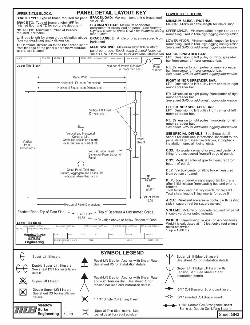
Meadow-Burke does not recommend the use of any type inserts other than those specified for attaching tilt-up braces and assumes no responsibility if used.
The floor slab has not been checked or designed by Meadow-Burke.

ENGINEERING
MEADOW BURKE
3 3
Wn = Actual Width of Panel Applied to Each Brace

5027
.71
16.0
03.
1349
27.7
116
.00
3.26
4827
.71
16.0
03.
463.
3947
27.7
116
.00
3.69
3.61
3.53
4627
.71
16.0
03.
953.
863.
773.
6845
27.0
017
.17
4.22
4.12
4.02
3.92
4426
.40
18.0
84.
464.
354.
244.
1443
25.7
519
.00
4.69
4.58
4.46
4.35
23.3
813
.50
5.57
4225
.75
19.0
04.
934.
814.
684.
5523
.38
13.5
05.
8341
25.7
519
.00
5.20
5.05
4.91
4.76
23.3
813
.50
6.26
6.10
4025
.75
19.0
05.
495.
325.
154.
9923
.38
13.5
06.
736.
576.
4039
25.7
519
.00
5.80
5.60
5.42
5.24
23.3
813
.50
7.28
7.09
6.90
6.71
3825
.75
19.0
06.
135.
915.
705.
5022
.80
14.4
68.
057.
847.
617.
4037
25.7
519
.00
6.50
6.25
6.01
5.78
22.2
015
.37
8.83
8.58
8.34
8.09
3625
.75
19.0
06.
906.
616.
346.
0821
.75
16.0
09.
569.
289.
008.
7228
14.7
58.
5012
.79
3525
.75
19.0
07.
347.
006.
706.
4121
.75
16.0
010
.17
9.83
9.51
9.19
19.0
511
.00
8.70
2714
.75
8.50
14.1
113
.64
3425
.75
19.0
07.
817.
437.
086.
7721
.75
16.0
010
.82
10.4
410
.06
9.70
19.0
511
.00
9.44
9.18
2614
.75
8.50
15.1
614
.58
3325
.75
19.0
08.
327.
917.
517.
1521
.75
16.0
011
.53
11.1
010
.66
10.2
519
.05
11.0
010
.32
10.0
09.
7025
14.7
58.
5016
.97
16.3
015
.62
2412
.12
7.00
14.0
07.
6232
25.7
519
.00
8.90
8.41
7.97
7.56
21.7
516
.00
12.3
311
.81
11.3
110
.84
19.0
511
.00
10.9
810
.62
10.2
624
14.4
09.
0420
.019
.18
18.3
317
.54
2312
.12
7.00
14.0
08.
498.
1931
25.7
519
.00
9.53
8.97
8.48
8.01
21.7
516
.00
13.2
112
.60
12.0
411
.49
18.6
011
.75
12.6
512
.24
11.8
311
.41
2313
.75
10.0
020
.020
.020
.020
.022
12.1
27.
0014
.00
9.22
8.83
3021
.75
16.0
014
.19
13.4
612
.81
12.1
918
.00
12.6
514
.16
13.6
713
.20
12.7
222
13.7
510
.00
20.0
20.0
20.0
20.0
2112
.12
7.00
14.0
010
.48
10.0
49.
5529
21.7
516
.00
15.2
514
.42
13.6
612
.97
17.7
513
.00
15.4
314
.86
14.3
013
.76
2113
.75
10.0
020
.020
.020
.020
.020
12.1
27.
0014
.00
12.1
211
.52
10.9
410
.36
2821
.75
16.0
016
.44
15.4
914
.60
13.8
017
.75
13.0
016
.63
15.9
715
.28
14.6
420
13.7
510
.00
20.0
20.0
20.0
20.0
1912
.12
7.00
14.0
013
.48
12.7
211
.97
11.2
927
21.7
516
.00
17.7
816
.65
15.6
414
.72
17.7
513
.00
17.9
817
.16
16.3
715
.61
1913
.75
10.0
020
.020
.020
.020
.018
12.1
27.
0014
.00
15.0
814
.13
13.1
512
.30
2621
.75
16.0
019
.29
17.9
516
.80
15.7
317
.75
13.0
019
.51
18.5
017
.59
16.6
818
13.7
510
.00
20.0
20.0
20.0
20.0
1711
.33
6.54
13.0
820
.019
.47
18.1
416
.90
2521
.75
16.0
020
.019
.42
18.0
616
.85
17.7
513
.00
20.0
20.0
18.9
017
.88
1713
.75
10.0
020
.020
.020
.020
.016
10.5
46.
0812
.17
20.0
20.0
20.0
20.0
2421
.75
16.0
020
.020
.019
.47
18.1
017
.75
13.0
020
.020
.020
.019
.20
1613
.75
10.0
020
.020
.020
.020
.015
9.74
5.63
11.2
520
.020
.020
.020
.023
21.7
516
.00
20.0
20.0
20.0
19.4
617
.75
13.0
020
.020
.020
.020
.015
13.7
510
.00
20.0
20.0
20.0
20.0
148.
945.
1710
.33
20.0
20.0
20.0
20.0
2217
.75
13.0
020
.020
.020
.020
.014
13.0
011
.00
20.0
20.0
20.0
20.0
138.
164.
719.
4220
.020
.020
.020
.021
17.7
513
.00
20.0
20.0
20.0
20.0
1312
.00
12.0
020
.020
.020
.020
.012
7.36
4.25
8.50
20.0
20.0
20.0
20.0
2017
.75
13.0
020
.020
.020
.020
.012
11.0
013
.00
20.0
20.0
20.0
20.0
117.
364.
258.
5020
.020
.020
.020
.019
17.7
513
.00
20.0
20.0
20.0
20.0
1110
.00
13.7
520
.020
.020
.020
.010
7.36
4.25
8.50
20.0
20.0
20.0
20.0
1817
.00
13.9
620
.020
.020
.020
.010
9.00
14.4
220
.020
.020
.020
.09
7.36
4.25
8.50
20.0
20.0
20.0
20.0
1716
.00
15.1
020
.020
.020
.020
.09
8.00
15.0
020
.020
.020
.020
.08
7.00
4.83
8.50
20.0
20.0
20.0
20.0
H
Sheet GNB3
SUPE
R 2
2 Tilt-
up B
race
Spa
cing
Tab
le A
©20
13
Bra
ce T
able
Leg
end
All
dim
ensi
ons
are
show
n in
uni
ts o
f fee
t. A
lway
s ro
und
the
dim
ensi
ons
for t
he p
anel
hei
ght b
elow
floo
r and
the
pane
l he
ight
abo
ve f
loor
, to
the
next
larg
er c
hart
valu
e. R
efer
ence
bra
ce d
etai
l on
Bra
ce D
esig
n N
otes
, she
et G
NB
1.
1.3.13
S0S2
S4S6
S0S2
S4S6
with
10'
Ext
ensi
on
L =
32.0
0'w
ith 5
' Ext
ensi
onL
= 27
.00'
This
bra
ce s
paci
ng ta
ble
has
been
des
igne
d fo
r an
ultim
ate
84 m
ph w
ind
with
a 1
yea
r mea
n re
curre
nce
inte
rval
. The
tabl
e sh
ould
be
used
in c
onju
nctio
n w
ith th
e no
tes
and
reco
mm
enda
tions
sho
wn
in th
e B
race
Des
ign
Not
es, s
heet
s G
NB
1, G
NB
2 an
d G
NB
5.
S FF
=M
axim
um b
race
spa
cing
for a
pan
el w
ith a
hei
ght b
elow
floo
r (or
top
of d
eadm
an w
hen
used
) equ
al to
"FF"
feet
. [ie
., th
e S
0co
lum
n yi
elds
the
max
imum
spa
cing
for a
pan
el w
ith n
o he
ight
bel
ow fl
oor,
the
S2
colu
mn
yiel
ds th
e m
axim
um s
paci
ng fo
r a
pane
l with
a 2
foot
max
imum
hei
ght b
elow
floo
r, et
c.]
Hei
ght o
f pan
el a
bove
floo
r or t
op o
f dea
dman
w
hen
used
.
Bra
ce in
sert
loca
tion
on fa
ce o
f pan
el a
bove
floo
r or
top
of d
eadm
an if
use
d.
H= V=
X= L=
Hor
izon
tal d
imen
sion
to fl
oor b
race
inse
rt fro
m
the
face
of t
he p
anel
whe
re th
e w
all b
race
in
serts
are
loca
ted.
Bra
ce le
ngth
for g
iven
V a
nd X
.
WAR
NIN
GSo
me
brac
es m
ay n
ot b
e av
aila
ble
at a
ll di
strib
utio
n lo
catio
ns.
Alw
ays
chec
k w
ith y
our
loca
l di
strib
utor
for b
race
ava
ilabi
lity
prio
r to
cast
ing
inse
rts
in fl
oor s
lab
or w
all p
anel
s.
S0S2
S4S6
VX
Inst
all.
Dim
s.
SUPE
R 1
7
S0S2
S4S6
HV
XV
XV
Xw
ithou
t Ext
ensi
onL
= 22
.0'
L =
17.0
0'In
stal
l. D
ims.
Inst
all.
Dim
s.In
stal
l. D
ims.
VX
LIn
stal
l. D
ims.
814
HDBR
ACE
S0S2
S4S6
H

7945
.00
26.0
01.
8778
45.0
026
.00
1.92
7745
.00
26.0
02.
001.
9776
45.0
026
.00
2.08
2.05
2.02
7545
.00
26.0
02.
172.
142.
112.
0874
44.4
027
.06
2.30
2.26
2.23
2.20
7343
.80
28.0
22.
422.
382.
352.
3172
43.2
028
.94
2.54
2.50
2.46
2.42
7142
.60
29.8
22.
662.
622.
582.
5470
42.0
030
.66
2.78
2.74
2.70
2.65
6941
.75
31.0
02.
892.
842.
792.
7568
41.7
531
.00
2.98
2.93
2.88
2.83
6741
.75
31.0
03.
083.
022.
972.
9266
41.7
531
.00
3.18
3.12
3.06
3.01
6541
.75
31.0
03.
293.
233.
163.
1064
41.7
531
.00
3.40
3.33
3.27
3.20
36.3
721
.00
3.34
6341
.75
31.0
03.
523.
453.
373.
3036
.37
21.0
03.
513.
4562
41.7
531
.00
3.65
3.57
3.49
3.41
36.3
721
.00
3.63
3.56
6141
.75
31.0
03.
783.
693.
613.
5236
.37
21.0
03.
823.
753.
6860
41.7
531
.00
3.92
3.82
3.73
3.64
36.0
021
.63
4.10
4.03
3.96
3.88
5941
.75
31.0
04.
073.
963.
863.
7635
.40
22.6
04.
374.
304.
224.
1458
41.7
531
.00
4.22
4.11
4.00
3.89
34.8
023
.52
4.64
4.56
4.48
4.39
5741
.75
31.0
04.
394.
264.
144.
0334
.20
24.3
84.
924.
834.
734.
6432
.04
18.5
04.
8756
41.7
531
.00
4.56
4.43
4.30
4.17
33.7
525
.00
5.17
5.07
4.97
4.87
32.0
418
.50
5.14
5.05
5541
.75
31.0
04.
754.
604.
464.
3333
.75
25.0
05.
385.
275.
165.
0532
.04
18.5
05.
335.
2354
41.7
531
.00
4.94
4.78
4.63
4.49
33.7
525
.00
5.60
5.48
5.36
5.24
32.0
418
.50
5.64
5.53
5.42
5341
.75
31.0
05.
144.
974.
814.
6533
.75
25.0
05.
835.
705.
565.
4332
.04
18.5
05.
995.
875.
755.
6352
41.7
531
.00
5.36
5.17
5.00
4.83
33.7
525
.00
6.08
5.93
5.78
5.64
31.2
019
.89
6.54
6.41
6.27
6.14
5141
.75
31.0
05.
595.
395.
205.
0233
.75
25.0
06.
346.
186.
025.
8630
.60
20.8
07.
006.
856.
716.
5650
41.7
531
.00
5.84
5.62
5.41
5.22
33.7
525
.00
6.63
6.44
6.26
6.09
30.0
021
.66
7.46
7.30
7.15
6.99
27.7
116
.00
7.28
5049
41.7
531
.00
6.11
5.86
5.64
5.43
33.7
525
.00
6.92
6.72
6.52
6.34
29.7
522
.00
7.85
7.68
7.50
7.33
27.7
116
.00
7.58
4948
41.7
531
.00
6.39
6.12
5.88
5.65
33.7
525
.00
7.24
7.02
6.80
6.59
29.7
522
.00
8.21
8.02
7.82
7.63
27.7
116
.00
8.05
7.89
4847
41.7
531
.00
6.69
6.40
6.13
5.88
33.7
525
.00
7.58
7.33
7.10
6.87
29.7
522
.00
8.60
8.38
8.16
7.95
27.7
116
.00
8.59
8.40
8.21
4746
41.7
531
.00
7.01
6.69
6.40
6.13
33.7
525
.00
7.95
7.67
7.41
7.16
29.7
522
.00
9.02
8.77
8.53
8.29
27.7
116
.00
9.20
8.99
8.78
8.56
4645
33.7
525
.00
8.34
8.03
7.74
7.47
29.7
522
.00
9.46
9.18
8.91
8.65
27.0
017
.17
10.1
09.
869.
629.
3945
4433
.75
25.0
08.
768.
428.
107.
8029
.75
22.0
09.
939.
629.
329.
0326
.40
18.0
810
.91
10.6
610
.39
10.1
444
4333
.75
25.0
09.
208.
848.
488.
1529
.75
22.0
010
.44
10.1
09.
769.
4425
.75
19.0
011
.76
11.4
911
.19
10.9
143
4233
.75
25.0
09.
689.
278.
898.
5329
.75
22.0
010
.98
10.6
010
.23
9.87
25.7
519
.00
12.3
712
.05
11.7
311
.41
4241
33.7
525
.00
10.2
09.
759.
338.
9329
.75
22.0
011
.58
11.1
410
.73
10.3
325
.75
19.0
013
.04
12.6
712
.31
11.9
441
4033
.75
25.0
010
.77
10.2
69.
799.
3629
.75
22.0
012
.22
11.7
211
.27
10.8
325
.75
19.0
013
.76
13.3
312
.92
12.5
240
3933
.75
25.0
011
.37
10.8
110
.29
9.82
29.7
522
.00
12.9
012
.35
11.8
411
.37
25.7
519
.00
14.5
314
.05
13.5
813
.14
3938
33.7
525
.00
12.0
311
.41
10.8
310
.31
29.7
522
.00
13.6
513
.04
12.4
611
.93
25.7
519
.00
15.3
714
.83
14.2
913
.79
3837
29.7
522
.00
14.4
613
.77
13.1
312
.54
25.7
519
.00
16.2
915
.66
15.0
614
.49
3736
29.7
522
.00
15.3
514
.57
13.8
613
.20
25.7
519
.00
17.2
916
.57
15.9
015
.25
3635
29.7
522
.00
16.3
315
.43
14.6
413
.91
25.7
519
.00
18.4
017
.55
16.7
916
.07
3534
29.7
522
.00
17.3
816
.39
15.4
814
.68
25.7
519
.00
19.5
718
.64
17.7
616
.97
3433
29.7
522
.00
18.5
317
.43
16.4
115
.50
25.7
519
.00
20.0
019
.82
18.8
217
.92
3332
29.7
522
.00
19.8
118
.55
17.4
216
.40
25.7
519
.00
20.0
020
.00
19.9
818
.95
3231
29.7
522
.00
20.0
019
.78
18.5
317
.38
25.7
519
.00
20.0
020
.00
20.0
020
.00
31
Sheet GNB4
VX
Inst
alla
tion
Dim
ensi
ons
Tilt-
up B
race
Spa
cing
Tab
le B
©20
13
This
bra
ce s
paci
ng ta
ble
has
been
des
igne
d fo
r an
ultim
ate
84 m
ph w
ind
with
a 1
yea
r mea
n re
curr
ence
inte
rval
. The
tabl
e sh
ould
be
used
in
conj
unct
ion
with
the
note
s an
d re
com
men
datio
ns s
how
n in
the
Brac
e D
esig
n N
otes
, she
ets
GN
B1, G
NB2
, and
GN
B5.
S FF
=M
axim
um b
race
spa
cing
for a
pan
el w
ith a
hei
ght b
elow
floo
r (or
top
of d
eadm
an w
hen
used
) equ
al to
"FF"
feet
. [ie
., th
e S 0
colu
mn
yiel
ds
the
max
imum
spa
cing
for a
pan
el w
ith n
o he
ight
bel
ow fl
oor,
the
S 2co
lum
n yi
elds
the
max
imum
spa
cing
for a
pan
el w
ith a
2 fo
ot m
axim
um h
eigh
t be
low
floo
r, et
c.]
Bra
ce T
able
Leg
end
H= V= X= L=
All d
imen
sion
s ar
e sh
own
in u
nits
of f
eet.
Alw
ays
roun
d th
e di
men
sion
s fo
r the
pan
el h
eigh
t bel
ow fl
oor a
nd th
e pa
nel h
eigh
tabo
ve
floor
, to
the
next
larg
er c
hart
valu
e. R
efer
ence
bra
ce d
etai
l on
Brac
e D
esig
n N
otes
, she
et G
NB1
.
1.3.13
Hor
izon
tal d
imen
sion
to fl
oor b
race
inse
rt fro
m th
e fa
ce o
f the
pan
el
whe
re th
e w
all b
race
inse
rts a
re lo
cate
d.Br
ace
leng
th fo
r giv
en V
and
X.
WARNING: Some braces may not be available at all distribution locations. Always check with your local distributor for brace availability prior to casting inserts in floor slab or wall panels.
Hei
ght o
f pan
el a
bove
floo
r or t
op o
f dea
dman
whe
n us
ed.
Brac
e in
sert
loca
tion
on fa
ce o
f pan
el a
bove
floo
r or t
op o
f dea
dman
if
used
.
H
SUPE
R 3
2
with
10'
Ext
.+10
' Ext
.L
=52.
00'
S0S2
S4S6
S0S2
S4S6
S0S2
S4S6
S0S2
S4S6
VX
VX
VX
Inst
alla
tion
Dim
ensi
ons
Inst
alla
tion
Dim
ensi
ons
Inst
alla
tion
Dim
ensi
ons
with
10'
Ext
ensi
onL
=42.
00'
with
5' E
xten
sion
L =3
7.00
'w
ithou
t Ext
entio
nsL
=32.
00'
H

ENGINEERING
MEADOW BURKE
1 3 3
Typical Panel Example
Determine panel height above floor, H, and panel height below floor, FF.
Determine brace insert locations V and X.
75 90
Determine brace length L.
Determine maximum brace spacing, SFF.
5.28
Determine the minimum number of braces required per panel.
5.285.28 26
number
Determine the horizontal brace insert locations.
5 28
7945
.00
26.0
05.
2378
45.0
026
.00
5.37
7745
.00
26.0
05.
595.
5176
45.0
026
.00
5.83
5.75
5.66
7545
.00
26.0
06.
096.
005.
915.
8274
44.4
027
.06
6.44
6.35
6.25
6.16
7343
.80
28.0
26.
786.
686.
586.
4772
43.2
028
.94
7.12
7.01
6.90
6.79
7142
.60
29.8
27.
467.
347.
237.
1270
42.0
030
.66
7.80
7.68
7.56
7.44
6941
.75
31.0
08.
097.
967.
837.
7068
41.7
531
.00
8.35
8.22
8.07
7.93
6741
.75
31.0
08.
638.
488.
338.
1766
41.7
531
.00
8.92
8.75
8.59
8.43
6541
.75
31.0
09.
239.
048.
878.
6964
41.7
531
.00
9.54
9.35
9.15
8.97
36.3
721
.00
6.67
6341
.75
31.0
09.
889.
679.
469.
2536
.37
21.0
07.
006.
8962
41.7
531
.00
10.2
310
.00
9.78
9.56
36.3
721
.00
7.24
7.11
6141
.75
31.0
010
.60
10.3
510
.11
9.87
36.3
721
.00
7.61
7.48
7.35
6041
.75
31.0
011
.00
10.7
210
.46
10.2
036
.00
21.6
38.
198.
047.
907.
7559
41.7
531
.00
11.4
111
.11
10.8
310
.55
35.4
022
.60
8.73
8.57
8.41
8.26
5841
.75
31.0
011
.84
11.5
211
.21
10.9
234
.80
23.5
29.
279.
118.
938.
7657
41.7
531
.00
12.3
011
.95
11.6
211
.30
34.2
024
.38
9.81
9.63
9.45
9.26
5641
.75
31.0
012
.79
12.4
112
.05
11.7
033
.75
25.0
010
.32
10.1
29.
939.
7355
41.7
531
.00
13.3
012
.89
12.5
012
.13
33.7
525
.00
10.7
410
.51
10.3
010
.08
5441
.75
31.0
013
.84
13.4
012
.97
12.5
833
.75
25.0
011
.17
10.9
310
.69
10.4
553
41.7
531
.00
14.4
213
.94
13.4
813
.05
33.7
525
.00
11.6
411
.37
11.1
010
.84
5241
.75
31.0
015
.03
14.5
114
.01
13.5
433
.75
25.0
012
.13
11.8
411
.54
11.2
551
41.7
531
.00
15.6
815
.11
14.5
814
.07
33.7
525
.00
12.6
612
.33
12.0
111
.69
5041
.75
31.0
016
.38
15.7
515
.17
14.6
233
.75
25.0
013
.22
12.8
512
.50
12.1
549
41.7
531
.00
17.1
216
.44
15.8
015
.21
33.7
525
.00
13.8
213
.41
13.0
212
.65
4841
.75
31.0
017
.90
17.1
716
.47
15.8
333
.75
25.0
014
.45
14.0
113
.57
13.1
647
41.7
531
.00
18.7
517
.94
17.1
916
.49
33.7
525
.00
15.1
314
.63
14.1
613
.71
4641
.75
31.0
019
.65
18.7
617
.95
17.1
933
.75
25.0
015
.86
15.3
114
.79
14.2
945
33.7
525
.00
16.6
516
.03
15.4
514
.91
4433
.75
25.0
017
.47
16.8
016
.16
15.5
743
33.7
525
.00
18.3
617
.64
16.9
216
.27
4233
.75
25.0
019
.32
18.5
117
.74
17.0
241
33.7
525
.00
20.3
719
.45
18.6
217
.82
4033
.75
25.0
021
.50
20.4
719
.54
18.6
839
33.7
525
.00
22.7
021
.57
20.5
419
.61
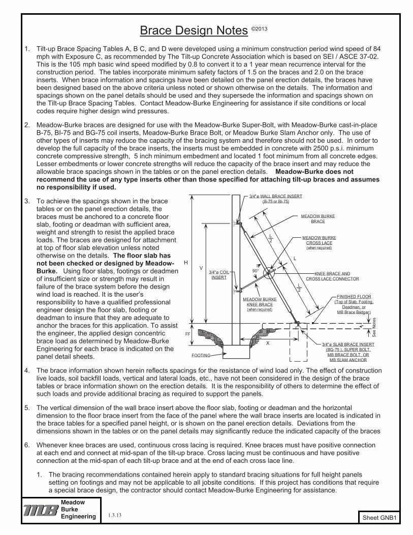
Sheet GNB6
Tilt-
up B
race
Spa
cing
Tab
le C
©20
13
This
bra
ce s
paci
ng ta
ble
has
been
des
igne
d fo
r an
ultim
ae 8
4 m
ph w
ind
with
a 1
yea
r mea
n re
curr
ence
inte
rval
. The
tabl
e sh
ould
be
used
in c
onju
nctio
n w
ith th
e no
tes
and
reco
mm
enda
tions
sh
own
in th
e Br
ace
Des
ign
Not
es, s
heet
s G
NB1
, GN
B2, a
nd G
NB5
. N
ote
valu
es s
how
n re
quire
br
aces
to b
e at
tach
ed to
Bad
gers
or a
6" t
hick
x 3
,000
psi
sla
b w
ith a
n M
B Br
ace
Bolt.
S FF
=M
axim
um b
race
spa
cing
for a
pan
el w
ith a
hei
ght b
elow
floo
r (or
top
of d
eadm
an w
hen
used
) eq
ual t
o "F
F" fe
et. [
ie.,
the
S 0co
lum
n yi
elds
the
max
imum
spa
cing
for a
pan
el w
ith n
o he
ight
bel
ow
floor
, the
S2
colu
mn
yiel
ds th
e m
axim
um s
paci
ng fo
r a p
anel
with
a 2
foot
max
imum
hei
ght b
elow
floo
r, et
c.]
Bra
ce T
able
Leg
end
H=
V= X= L=
All d
imen
sion
s ar
e sh
own
in u
nits
of f
eet.
Alw
ays
roun
d th
e di
men
sion
s fo
r the
pan
el h
eigh
t bel
ow
floor
and
the
pane
l hei
ght a
bove
flo
or, t
o th
e ne
xt la
rger
cha
rt va
lue.
Ref
eren
ce b
race
det
ail o
n Br
ace
Des
ign
Not
es, s
heet
GN
B1.
3
Hor
izon
tal d
imen
sion
to fl
oor b
race
inse
rt fro
m th
e fa
ce o
f the
pan
el w
here
the
wal
l bra
ce in
serts
are
lo
cate
d.Br
ace
leng
th fo
r giv
en V
and
X.
WARNING: Some braces may not be available at all distribution locations. Always check with your local distributor for brace availability prior to casting inserts in floor slab or wall panels.
Hei
ght o
f pan
el a
bove
floo
r or t
op o
f dea
dman
w
hen
used
.Br
ace
inse
rt lo
catio
n on
face
of p
anel
abo
ve fl
oor o
r to
p of
dea
dman
if u
sed.
HS 0
S2S4
S6V
XV
XIn
stal
l. D
ims.
Inst
all.
Dim
s.
S0S2
S4S6
SUPE
R 5
2L=
52.0
0'SU
PER
42
L=42
.00'
1.3.13

ENGINEERING
MEADOW BURKE
1 3 3
Cylindrical Deadman 13
Warning:
5333
.13
19.1
238
.25
4.13
4.04
3.95
3.86
5232
.50
18.7
637
.53
4.39
4.29
4.19
4.09
5131
.88
18.4
036
.81
4.66
4.55
4.45
4.34
5031
.25
18.0
436
.08
4.96
4.85
4.73
4.62
4930
.63
17.6
835
.36
5.12
5.00
4.87
4.76
4830
.00
17.3
234
.64
5.24
5.12
4.99
4.87
4729
.38
16.9
633
.92
5.38
5.24
5.11
4.98
4628
.75
16.6
033
.20
5.52
5.37
5.24
5.10
4528
.13
16.2
432
.48
5.66
5.51
5.37
5.23
1.08
1.05
4427
.50
15.8
831
.75
5.81
5.66
5.51
5.36
1.23
1.20
1.17
1.14
4326
.88
15.5
231
.03
5.97
5.82
5.65
5.50
1.41
1.38
1.34
1.30
4226
.25
15.1
630
.31
6.14
5.97
5.81
5.64
1.63
1.58
1.54
1.50
4125
.63
14.7
929
.59
6.31
6.13
5.96
5.79
1.88
1.83
1.78
1.72
4025
.00
14.4
328
.87
6.50
6.31
6.13
5.95
2.18
2.12
2.06
2.00
3924
.38
14.0
728
.15
6.69
6.50
6.30
6.12
2.53
2.46
2.39
2.31
3823
.75
13.7
127
.42
6.90
6.70
6.49
6.29
2.96
2.88
2.79
2.70
2918
.13
10.4
620
.93
2.52
2.43
2.33
2.24
3723
.13
13.3
526
.70
7.12
6.90
6.68
6.47
3.47
3.37
3.26
3.16
2817
.50
10.1
020
.21
2.86
2.75
2.64
2.53
17.5
010
.10
20.2
14.
494.
324.
143.
9736
22.5
012
.99
25.9
87.
357.
126.
896.
664.
103.
963.
843.
7127
16.8
89.
7419
.49
3.26
3.13
3.00
2.87
16.8
89.
7419
.49
5.22
5.01
4.80
4.59
3521
.88
12.6
325
.26
7.61
7.35
7.11
6.87
4.85
4.68
4.53
4.38
2616
.25
9.38
18.7
63.
743.
583.
433.
2716
.25
9.38
18.7
66.
105.
845.
595.
3434
21.2
512
.27
24.5
47.
867.
607.
337.
095.
765.
575.
385.
2025
15.6
39.
0218
.04
4.31
4.11
3.93
3.75
15.6
39.
0218
.04
7.18
6.85
6.54
6.24
3320
.78
12.0
024
.00
8.20
7.92
7.63
7.35
6.69
6.46
6.23
6.00
2415
.00
8.66
17.3
24.
984.
764.
534.
3215
.00
8.66
17.3
28.
478.
097.
707.
3532
20.7
812
.00
24.0
08.
768.
438.
107.
787.
156.
886.
616.
3523
14.3
88.
3016
.60
5.79
5.53
5.25
5.00
14.3
88.
3016
.60
10.0
79.
639.
148.
6931
20.7
812
.00
24.0
09.
388.
988.
618.
247.
667.
337.
036.
7322
13.7
57.
9415
.88
6.78
6.46
6.14
5.82
13.7
57.
9415
.88
12.0
711
.50
10.9
310
.36
3020
.78
12.0
024
.00
10.0
89.
609.
178.
758.
237.
847.
487.
1421
13.1
37.
5815
.16
8.01
7.60
7.22
6.82
13.1
37.
5815
.16
13.6
512
.96
12.3
111
.63
2920
.78
12.0
024
.00
10.8
410
.29
9.77
9.31
8.85
8.40
7.98
7.60
2012
.56
7.25
14.5
09.
488.
968.
488.
0112
.56
7.25
14.5
014
.50
13.7
012
.96
12.2
428
20.7
812
.00
24.0
011
.68
11.0
510
.44
9.90
9.54
9.02
8.53
8.09
1912
.56
7.25
14.5
010
.54
9.89
9.27
8.72
12.5
67.
2514
.50
16.1
215
.13
14.1
813
.34
2720
.78
12.0
024
.00
12.6
311
.88
11.1
910
.56
10.3
19.
709.
148.
6218
12.5
67.
2514
.50
11.7
910
.99
10.1
99.
5012
.56
7.25
14.5
018
.03
16.8
015
.58
14.5
326
20.7
812
.00
24.0
013
.71
12.8
112
.02
11.2
911
.19
10.4
59.
819.
2217
12.5
67.
2514
.50
13.2
812
.22
11.2
510
.39
12.5
67.
2514
.50
20.0
18.6
817
.21
15.9
025
20.7
812
.00
24.0
014
.93
13.8
512
.92
12.0
912
.19
11.3
110
.55
9.87
1612
.56
7.25
14.5
015
.08
13.6
712
.50
11.4
212
.56
7.25
14.5
020
.020
.019
.11
17.4
724
20.7
812
.00
24.0
016
.27
15.0
313
.93
12.9
913
.28
12.2
711
.37
10.6
115
12.5
67.
2514
.50
17.2
915
.40
13.9
012
.61
12.5
67.
2514
.50
20.0
20.0
20.0
20.0
2320
.78
12.0
024
.00
17.8
016
.37
15.0
613
.96
14.5
313
.36
12.3
011
.40
1412
.56
7.25
14.5
019
.84
17.4
915
.55
14.0
112
.56
7.25
14.5
020
.020
.020
.020
.022
20.7
812
.00
24.0
019
.56
17.8
316
.35
15.0
515
.97
14.5
613
.35
12.2
913
12.0
08.
0014
.50
20.0
20.0
17.8
115
.90
12.0
08.
1414
.50
20.0
20.0
20.0
20.0
2120
.00
13.2
724
.00
20.0
20.0
19.0
717
.48
18.7
717
.01
15.5
714
.27
1211
.00
9.45
14.5
020
.020
.020
.018
.33
11.0
09.
4514
.50
20.0
20.0
20.0
20.0
2019
.00
14.6
624
.00
20.0
20.0
20.0
20.0
21.8
719
.71
17.9
616
.45
1110
.00
10.5
014
.50
20.0
20.0
20.0
20.0
10.0
010
.50
14.5
020
.020
.020
.020
.019
18.0
015
.87
24.0
020
.020
.020
.020
.020
.020
.020
.018
.62
109.
0011
.33
14.5
020
.020
.020
.020
.09.
0011
.33
14.5
020
.020
.020
.020
.018
17.0
016
.94
24.0
020
.020
.020
.020
.020
.020
.020
.020
.09
8.00
12.0
014
.50
20.0
20.0
20.0
20.0
8.00
12.0
014
.50
20.0
20.0
20.0
20.0
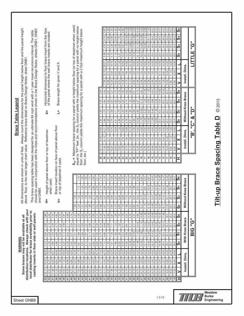
H
"B',
"C"
& "
D"
VX
LIn
stal
l. D
ims.
VX
LIn
stal
l. D
ims. LI
TTLE
"G
"
S0S2
S4S6
S0S2
S4S6
Tilt-
up B
race
Spa
cing
Tab
le D
©20
13
Sheet GNB8
With
out K
nee
Bra
ce
1.3.13
WAR
NIN
GSo
me
brac
es m
ay n
ot b
e av
aila
ble
at a
ll di
strib
utio
n lo
catio
ns.
Alw
ays
chec
k w
ith y
our
loca
l dis
trib
utor
for b
race
ava
ilabi
lity
prio
r to
cast
ing
inse
rts
in fl
oor s
lab
or w
all p
anel
s.
H
BIG
"G
"W
ith K
nee
Bra
ceW
ithou
t Kne
e B
race
VX
LIn
stal
l. D
ims.
S0S2
S4S6
S0S2
S4S6
Bra
ce T
able
Leg
end
All
dim
ensi
ons
are
show
n in
uni
ts o
f fee
t. A
lway
s ro
und
the
dim
ensi
ons
for t
he p
anel
hei
ght b
elow
floo
r and
the
pane
l hei
ght
abov
e fl
oor,
to th
e ne
xt la
rger
cha
rt va
lue.
Ref
eren
ce b
race
det
ail o
n B
race
Des
ign
Not
es, s
heet
GN
B1.
This
bra
ce s
paci
ng ta
ble
has
been
des
igne
d fo
r an
ultim
ate
84 m
ph w
ind
with
a 1
yea
r mea
n re
curre
nce
inte
rval
. The
tabl
e sh
ould
be
used
in c
onju
nctio
n w
ith th
e no
tes
and
reco
mm
enda
tions
sho
wn
in th
e B
race
Des
ign
Not
es, s
heet
s G
NB
1, G
NB
2 an
d G
NB
5.
S FF
=M
axim
um b
race
spa
cing
for a
pan
el w
ith a
hei
ght b
elow
floo
r (or
top
of d
eadm
an w
hen
used
) eq
ual t
o "F
F" fe
et. [
ie.,
the
S0
colu
mn
yiel
ds th
e m
axim
um s
paci
ng fo
r a p
anel
with
no
heig
ht b
elow
flo
or, t
he S
2co
lum
n yi
elds
the
max
imum
spa
cing
for a
pan
el w
ith a
2 fo
ot m
axim
um h
eigh
t bel
ow
floor
, etc
.]
Hei
ght o
f pan
el a
bove
floo
r or t
op o
f dea
dman
w
hen
used
.
Bra
ce in
sert
loca
tion
on fa
ce o
f pan
el a
bove
floo
r or
top
of d
eadm
an if
use
d.
H= V=
X= L=
Hor
izon
tal d
imen
sion
to fl
oor b
race
inse
rt fro
m th
e fa
ce
of th
e pa
nel w
here
the
wal
l bra
ce in
serts
are
loca
ted.
Bra
ce le
ngth
for g
iven
V a
nd X
.

ENGINEERING
MEADOW BURKE
1 3 3
MB Brace Badger™ Helical Ground Anchor System 13
ALL
INSTALLATION REQUIREMENTS
torque of 2,200 ft-lbs
SAFETY NOTES

ENGINEERING
MEADOW BURKE
3 3

If you are reading this...You should be a TCA member.
In the Tilt-Up industry, there is only one way to network with the industry’s leading professionals, gain access to valuable marketing and technical information as well as attend educational seminars to increase your knowledge – join the Tilt-Up Concrete Association (TCA)!
Join the TCA today for the following benefits: • Discounts on educational seminars and the TCA Convention • Access to the TCA Achievement Awards program • Access to technical and marketing literature to grow your business • Networking opportunities with industry leaders • Tilt-Up Today delivered free on a quarterly basis • Company contact information included on our online member directory • Access to members only portion of www.tilt-up.org
http://www.tilt-up.org/tca/whyjoin.htm

MEMBERSHIP APPLICATION Join the Tilt-Up Concrete Association and help expand this industry while building your business.
You have our support!
Company:
Ship to Address:
Bill to Address (if different than above):
City: State: Zip: Country:
Phone: ( _) - - Fax: ( ) - -
Website: Email:
Authorized by: Date:
� VISA � MasterCard � Am Ex Credit Card #:
Name On Card: Exp. Date: ___ CVC #:
Note: Dues can be paid by check. All funds must be in U.S. Currency.
TCA Designated Contact (Primary):
Name: Title: Email:
Additional Contacts (Add more sheets as necessary):
Name: Title: Email:
Name: Title: Email:
Name: Title: Email:
Name: Title: Email:
MAIL OR FAX THIS APPLICATION FORM TODAY!Tilt-Up Concrete Association
P.O. Box 204, Mount Vernon, Iowa 52314 • Ph: 319-895-6911 • Fax: 320.213.5555 REGISTER Online www.tilt-up.org
� Global Associate……………….…. $1,100 � Contractor…………………………….. $750 � Local Associate2……………….…….. $600 � Professional Engineering Firm3…... $500 List States of License:______________________ ________________________________________� Developer/Owner….………………… $500
� Professional Architectural Firm3…... $500 List States of License:______________________ ________________________________________� Consultant4…………………………… $500 � Sustaining Member5………………… $2000 � Educator……………………………… $75� Specialty Trade6……………………… $500
Notes: 1 Member dues extend from Jan. 1 - Dec. 31. Dues are prorated on a quarterly basis through the first half of the year. 2 Local Associate is defined as distributing in home state and any adjoining states only. 3 Professional Firm is defined as a State- or Province-licensed firm to practice engineering or architecture.
4 Consultant is defined as a provider of professional services or expertise that is not a licensed engineer or architect. 5 Sustaining Member is a member of any aforementioned category wanting to identify a higher level of commitment
to the Tilt-Up industry. .Dues contribute to the Student Design Competition, Code Research & other initiatives. 6 Specialty Trade is a category of membership for trades other than concrete that frequent Tilt-Up projects..
Annual Dues1: Please Check One