CSCI 4163 / CSCI 6904 Human-Computer Interaction web.cs.dal/~ hawkey /4163

INSTALLATION INSTRUCTIONSLumascape Lighting Industries Pty Ltd38-44 Enterprise Street, Cleveland, QLD 4163, AustraliaPO Box 1875, Cleveland D.C., QLD 4163, AustraliaT 07 3286 2299F 07 3286 6599E [email protected] www.lumascape.com.au
IN0149 - 25 July 2014Copyright ©2014 Lumascape Lighting Industries Pty. Ltd. ABN 21 010 572 773www.lumascape.com.au
LS393LED: Pre-installationA.C.N. 0105 72 773
MODEL: LS647 / LS647-K MOUNTING ACCESSORIES
Warranty voided if not installed as per installation instructions
326
mm
min
gravel
finished floor level
hole Ø179 mm
Finished surface level to be flush with top surface of collar.
GENERAL ASSEMBLYWaterproof quick connector, Submersible plug and cable. Ensure free cable reaches beyond height of collar for luminaire connection.
Mounting collar.Brackets to anchor sleeve and arrest movement of collar in concrete.Stainless steel sleeve.
Styrofoam plug. (Use if required. Ensure removal after for drainage).
CAUTION: Do not pinch or cut cable beneath sleeve.
Factory supplied J-Box with 25 mm conduit entries.
Use electrical grade epoxy to fill the J-box after connections have been made and tested to ensure water-proofing.
Suitable for LS647-K
DANGERISOLATE LUMINAIRE FROM POWERFailure to isolate power supply before installation or maintenance may result in fire, serious injury, electric shock, death and may damage the luminaire.
DO NOT OVERTIGHTEN
NO DOWNWARD FORCE
NO POWER TOOLS
WARNING
Power supply must be isolated prior to connection or disconnection of cables. Failure to do so will result in damage to the luminaire components.
Type 84 cable entry:MICRO ANTILEACH 3M CABLE ENTRY
Type 85 or 87 cable entry:IP67 CONNECTION AND JUNCTION BOX
600 mm
Connectto 25 mm diameterconduit
Strip cable end and connect as required accordingto local wiring laws
170 mm (minimumcable bend radius)
50 mm (minimumcable bend radius)
600 mm
200
mm
(min
imum
)
Alternate bottom cable entry
690 mm (maximum distance to conduit)
Flexible armoured cable Flexible cable (requires mechanical protection)
3000 mmBottom cable entry
65 m
m(m
inim
um)
600 mm
Connectto 25 mm diameterconduit
Strip cable end and connect as required accordingto local wiring laws
170 mm (minimumcable bend radius)
50 mm (minimumcable bend radius)
600 mm
200
mm
(min
imum
)
Alternate bottom cable entry
690 mm (maximum distance to conduit)
Flexible armoured cable Flexible cable (requires mechanical protection)
3000 mmBottom cable entry
65 m
m(m
inim
um)
supplyconduit
where possibleposition j-box
within void
finishedsurfacelevel
Quick connectorcable
foamplug
Hole detail - section viewLayout luminaire locations as required. Use discretion in placement, luminaire may become hot and could burn. Luminaire cavity should be as shown. Ensure gravel or similar medium forms the bottom of cavity to allow drainage.
1.Supply connection• Connect junction box supplied
and punch a hole in foam plug to pass through connector.
• Pack hole in plug around the cable to ensure concrete doesn’t enter the luminaire cavity. (Ensure the cap on the connector is secure)
2.
Connect in accordance with local wiring rules.
Epoxy sachet not supplied by Lumascape.
Use electrical grade epoxy to water proof elelectrical
connection in junction box.
3. 4. 5.Supply connection - Type 85 or 87 connection onlyConnect according to junction box installation instructions and local wiring rules.
Terminate and waterproof the connectionsConnect wiring and test prior to potting. Add electrical grade epoxy resin to water proof junction box.
SealUsing a screwdriver seal junction box. Ensure not to over tighten.
Power supply must be isolated prior to connection or disconnection of cables. Failure to do so will result in damage to the luminaire components.
NOTE: If ordered without junction box assembly, connect in accordance with local wiring rules.

IN0149 - 25 July 2014Copyright ©2014 Lumascape Lighting Industries Pty. Ltd. ABN 21 010 572 773www.lumascape.com.au
luminaire
Minimumdepth
factory suppliedanti-leach cable
Minimum length of cable protruding
from ground 100
mm
25 mm conduit
foam plugwhere possibleposition j-box
within void
Fit luminaire
When ready to install luminaire;
• Destroy foam plug and assemble luminaire.• Remove cover plate (if located).• Join Quick Connectors (do not dispose of cap).
9.
Fit sleeve, collar and cover plate
• Fit sleeve over foam plug. • Ensure enough cable is in the cavity to
connect to luminaire.• Position top lip of mounting collar to be flush
with finished surface level.• Screw cover plate, (available separately,
consult your Lumascape dealer), to mounting collar if required.
Pour concrete
Pour concrete. Check that the top surface of mounting collar is flush with the finished surface level.
stainless steel sleeve
mounting collar
finished surface level
cover plate
where possibleposition j-box
within void
concrete
finishedsurfacelevel
where possibleposition j-box
within void
Attach brackets
Position and use screws to attach brackets at the bottom of the lid before con-crete is poured.
6. 7. 8.
10. 11.Isolate and open luminaireEnsure the luminaire is electrically isolated. Loosen the screws. If necessary gently lever lid out with a large screwdriver.
Remove lidRemove lid and any accessories to expose reflector.
Power supply must be isolated prior to connection or disconnection of cables. Failure to do so will result in damage to the luminaire components.
12. Target gimbalRotate gimbal until Aiming Mark is targeted as desired.
13. Lock gimbalLock Gimbal. Whilst exerting downward pressure on gimbal, tighten rotational lock grub screw.
14.
15 min.
Air gap
Run luminaireLay lid partially over luminaire to allow a gap for any moisture present to evaporate prior to sealing. Connect to supply and allow to burn for 10-15 minutes. Seal luminaire.IMPORTANT - DO NOT ENERGISE WITHOUT PARTIALLY COVERING LAMP
5°
360°
15°
IN0149 - 25 July 2014Copyright ©2014 Lumascape Lighting Industries Pty. Ltd. ABN 21 010 572 773www.lumascape.com.au
WARNING - To reduce the risk of FIRE or INJURY:1. Luminaires and transformers to be installed by licensed electrical contractors.2. Luminaires to be used for intended purpose only. 3. Do not operate the luminaires with a missing or damaged parts.4. Use only genuine Lumascape parts to replace damaged or missing components.5. Refer to instructions for installation and operating requirements.6. Ensure installation complies with local regulations
Voltage insulation test (megger) will permanently damage product and will void warranty.
SAVE THESE INSTRUCTIONS.
SAFETY INSTRUCTIONS
Questions?Call +61 7 3286 2299
Email [email protected]
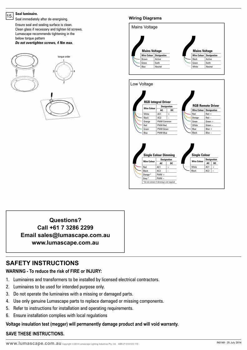
15.
torque order1
2
3 4
torque order1
2
3 4
Seal luminaire.Seal immediately after de-energising.
Ensure seal and sealing surface is clean.Clean glass if necessary and tighten lid screws.Lumascape recommends tightening in the below torque pattern Do not overtighten screws, 4 Nm max.
Wiring Diagrams
Low Voltage
RGB Remote DriverWire Colour Designation
Red Red +
Orange Red -
Green Green +
White Green -
Blue Blue +
Black Blue -
RGB Integral Driver
Wire ColourDesignation
AC DC
White AC1 +
Black AC2 -
Orange PWM Common
Red PWM Red
Green PWM Green
Blue PWM Blue
Single Colour Dimming
Wire ColourDesignation
AC DC
Red AC1 +
Black AC2 -
Orange * PWM +
Grey * PWM -* Do not connect if dimming is not required
Single Colour
Wire ColourDesignation
AC DC
White AC1 +
Black AC2 -
Mains Voltage
Mains VoltageWire Colour Designation
Black Active
Green Earth
White Neutral
Mains VoltageWire Colour Designation
Brown Active
Green Earth
Blue Neutral