Danger - Electric Regulator Manual 2003-09-20.pdf · A RM5 User Manual Warnings. Page 1 Danger...
44
A RM5 User Manual Warnings. Page 1 Danger Hazardous High Voltage Ground the control before servicing Remove all power and wait 10 minutes Verify that no voltage is present Failure to comply will result in death or serious injury. Warning Separate over current protection is required by the national electric code. The user is responsible for conforming with the national electric code and all applicable local codes which govern such practices as wiring protection, grounding, disconnects and other current protection. Warning Never exceed the maximum input voltage Exceeding the maximum input voltage causes catastrophic failure. Repair is impractical the control should be replaced. CAUTION Before MEGGER or DIELECTRIC testing the AC motor. Disconnect the AC motor from the RM5 control. Megger or dielectric testing will damage the control. Warning The RM5 is for 3 phase induction motors only. The RM5 will damage capacitor start motors.
-
Upload
hoangkhanh -
Category
Documents
-
view
218 -
download
0
Transcript of Danger - Electric Regulator Manual 2003-09-20.pdf · A RM5 User Manual Warnings. Page 1 Danger...

ARM5 User Manual Warnings.
Page 1
DangerHazardous High VoltageGround the control before servicing
Remove all power and wait 10 minutesVerify that no voltage is present
Failure to comply will result in death or serious injury.
WarningSeparate over current protection is required by the nationalelectric code. The user is responsible for conforming with thenational electric code and all applicable local codes whichgovern such practices as wiring protection, grounding,disconnects and other current protection.
WarningNever exceed the maximum input voltage
Exceeding the maximum input voltage causes catastrophic failure.
Repair is impractical the control should be replaced.
CAUTIONBefore MEGGER or DIELECTRIC testing the AC motor.
Disconnect the AC motor from the RM5 control. Megger or dielectric testing will damage the control.
WarningThe RM5 is for 3 phase induction motors only.The RM5 will damage capacitor start motors.

Page 2

Restoring the Factory settings4.28) Pg. 24Locking Programs & 400 Hz Motors4.27) Pg. 24Store and Copy Programs4.26)Pg. 24DC Braking (Note: Standard feature on 1 to 5 HP. Optional on 7 ½ HP or above)4.25) Pg. 22Power Interruption Controlled Stop Programming4.24) Pg. 21Power Interruption Ridethough4.23) Pg. 21Voltage Frequency Patterns (V/F Pattern)4.22) Pg. 20Level Speed Detection Signal4.21) Pg. 19Motor Slip and Stall Parameters4.20) Pg. 19Motor Ratings and Overload Parameters4.19) Pg. 18Carrier Frequency4.18) Pg. 17Motor Staring Parameters4.17) Pg. 17Overload Signal Parameters4.16) Pg. 16Overload Priority Selection (Motor or Inverter)4.15) Pg. 16Digital Meter Connection Diagram: Plug CN14.14b)Pg. 16Digital Meter Programming, Auxiliary4.14a) Pg. 16Analog Meter Programming, (outputs FM+ and FM- or GND)4.13) Pg. 16User Defined Meter (i.e. MPM) and RPM Calibration4.12) Pg. 15Keypad Default Display4.11) Pg. 15Frequency Bypass4.10) Pg. 15Operating Speed Range4.9) Pg. 14Speed Reference Scale (i.e. Speed Pot Voltage Scale)4.7) Pg. 14S-Curve Starting, Leveling and Stopping.4.6d) Pg. 13Secondary Acceleration & Deceleration4.6c) Pg. 13Acceleration & Deceleration Programming4.6b) Pg. 13Acceleration & Deceleration Scale4.6a) Pg. 13Output Terminal Programming: Y1, Y2 and Ta & Tb.4.5) Pg. 12Input Terminal Programming: X1 through X64.4) Pg. 12Multiple Speed Level Activation and Frequency Settings4.3) Pg. 12Maximum Frequency Programming4.2) Pg. 12Quick Start (Primary Settings)4.1) Pg. 11Programming InstructionsSection 4)Analog Keypad KP-202 Introduction3.4)Pg. 10Operating the RM5 without the keypad3.3)Pg. 10How to restore the factory program3.2)Pg. 9Keypad Operating Modes3.1)Pg. 9Keypad Operation Section 3)Carrier Frequency2.5)Pg. 8Wire Size & Specifications2.4)Pg. 8AC Line Reactors2.3)Pg. 8Motor Selection2.2)Pg. 7Operating Environment2.1)Pg. 7Physical InstallationSection 2)Input Power and Motor Specifications1.2)Pg. 5Physical Inspection1.1)Pg. 5Receiving and SpecificationsSection 1)
Table of Contents
Page 3

Elementary Wiring DiagramPg. 44Common SpecificationsPg. 43RM5 230V and 460V SpecificationsPg. 427 ½ to 75 HP Physical Dimension DiagramPg. 41½ to 5 HP Physical Dimension DiagramPg. 40Dynamic Braking Unit (DBU) Physical DimensionsPg. 39Keypad Physical Dimensions DiagramPg. 39Alphabetical List of Program FunctionsPages 35, 36, 37, 38Numerical List of Program FunctionsPages 31, 32, 33, 34AppendixSpeed Oscillation during Acceleration6.3)Pg. 29Keypad LED Display Fault Signals6.2)Pg. 29Clearing Faults6.1)Pg. 29Trouble ShootingSection 6)DIP Switch Programming5.4)Pg. 27Adjustment (ADJ.) Programming5.3)Pg. 26Rotary Switch (RSW) Operation5.2)Pg. 25Analog Keypad Factory Settings5.1)Pg. 25Analog Keypad KP-202 (Optional)Section 5)
Page 4

1. Receiving & Storage
Section 1.1 Physical InspectionWhen you receive the ERC RM5 AC Control unit avoid shock or vibration when unloading andtransporting the unit. This can damage the semiconductors or other components.Immediately upon receipt inspect the unit for the following;
Check to be certain the unit is clean of packing materials.Check for damage incurred during shipment, dents, scratches, etc.Inspect mechanical the parts, loose screws, terminals, etc.Inspect for, damaged, loose or shorted electronic components or connections.If you find damage, don’t connect power to it. The unit must be replaced or repaired.Connecting power could result in fire or further damage and could void warranty.
Promptly report damage or problems you found during inspection to Electric Regulator Corp.Telephone (760) 438-7873 Fax (760) 438-0437
Store the AC Control unit in a clean dry place in the package it was in shipped. Avoid storing theunit in a location with high temperatures, humidity, dust or corrosive gases. Outdoor storage isnot recommended.
Section 1.2 Input Power & Motor RatingCheck the identification label to confirm that the input power and the motor’s ratings arecompatible with the drive.
Identification Label On the right side of the drive please find the label with the model number, input power and output power. Example::
Model Number Scheme RM5 - 2 005 A B C
A: RM5.............. Series NumberB: 2.................... Voltage 208V, 220V, 230V
4.................... Voltage 400V, 440V, 460VC: 005................ Horsepower: Example 5 HP
Input Power Units rated from ½ HP to 5 HP can use 1 or 3 input power. Units 7 ½ HPand above require 3 input power
Motor Specification Inverter duty motor compatible with IGBT variable frequency control.
ERC RM5 AC Control; Section 1&2 (Receiving & Storage and Installation Location)
Page 5
Model No. RM5-2005 Input Power 200 to 230 VAC 50/60Hz Output Power 3.7kW/ 5 HP 17A

Page 6

2. Installation Location2.1 Operating EnvironmentThe ERC RM5 AC Control should be located in a operating environment that meets thefollowing conditions.
Ambient Temperature between 14o to 122o Fahrenheit (-10o to 50o Celsius).
Relative Humidity Avoid locations exceeding RH 90%.
Condensation Do not locate the unit where condensation occurs.
Altitude If located above 1000m/3280 ft above sea level, see table for power derating.
Corrosion Avoid locations with corrosive gases or liquids, for example: ocean air.
Contamination Avoid locations subject to dust or iron particles.
Hazardous Gases & Liquids The RM5 is not designed for explosive environments. Do notlocate the unit were it is subject to combustible or flammable gases or liquids.
Ventilation Mount the unit in a lengthwise vertical position to ensure proper coolingventilation. Provide not less than 5 inches (125 mm) top and bottom and 2 inches (50 mm)each side of clear space around the unit. If the unit is in a sealed enclosure, provide adequateventilation for air flow from top to bottom.
Shock & Vibration Avoid mounting the unit in a location subject to shock or vibration.
2.2 Motor SelectionThe motor should be a standard three phase induction motor. If normal operation is 15 Hz orabove a self ventilated motor adequate. If the motor is operated at a low speed for a long periodsof time. A separately ventilated motor is required. The motor's insulation should be a minimumof 100 M at 500V. Waterproof and submersible motors may have poor insulation due to sand andcontaminates abrading the insulation. The synchronous motor's starting current is greater thanstandard induction motor's. The V/F pattern is lower, a higher rating RM5 should be used. Whena motor designed to operate a 60 Hz is operated above 60 Hz the torque is decreaseddramatically.
Page 7

2.3 AC Line ReactorsIf the RM5's power is shared with equipment with SCR's, high power motors or welders, aAC line reactor should be used.If several RM5 are connected to one power source a AC line reactor should be used.
230V Table 460V Table
300A0.02 mH150 / 160600A0.01 mH150 / 160200A0.02 mH125 / 134400A0.02 mH125 / 134200A0.02 mH100 / 115400A0.02 mH100 / 115150A0.03 mH75 / 84300A0.02 mH75 / 84100A0.04 mH60 / 67200A0.02 mH60 / 67100A0.04 mH50 / 55200A0.02 mH50 / 55100A0.04 mH40 / 44150A0.03 mH40 / 4450A0.08 mH30 / 33100A0.04 mH30 / 3350A0.08 mH25 / 28100A0.04 mH25 / 2840A0.25 mH20 / 22100A0.04 mH20 / 2240A0.25 mH15 / 1850A0.08 mH15 / 1830A0.3 mH10 / 1350A0.08 mH10 / 1330A0.3 mH7.5 / 930A0.3 mH7.5 / 915A0.4 mH5 / 630A0.3 mH5 / 615A0.4 mH3 / 415A0.4 mH3 / 415A0.4 mH2 / 315A0.4 mH2 / 315A0.4 mH1 / 215A0.4 mH1 / 2
CurrentInductanceContinuousrated powerHP / KVA
CurrentInductanceContinuousrated powerHP / KVA
2.4 Wire Specifications The output wire must be rated for high temperature 600 C. The fuse ratings are selected toprotect the wire not the IGBTs. Output, 230V, 3 Phase, 0 to 60 Hz Output, 460V, 3 Phase, 0 to 60 Hz
130A000 AWG135A75250A500 MCM254A75100A00 AWG110A60200A300 MCM205A6090A1 AWG90A50160A250 MCM173A5075A2 AWG75A40130A000 AWG139A4060A3 AWG60A30100A0 AWG105A3050A4 AWG45A2590A1 AWG87A2540A6 AWG38A2070A2 AWG70A2030A8 AWG30A1550A4 AWG54A1530A8 AWG30A1035A6 AWG36A1015A10 AWG14A7 ½25A8 AWG28A7 ½10A12 AWG10A520A10 AWG19A5
FuseAmps
Minimum Size for 40 ft length
Full LoadAmpsH.P.Fuse
AmpsMinimum Size for 40 ft length
Full LoadAmpsH.P.
Section 2.5) Carrier FrequencyFunction code, F 081 programs the carrier frequency.
2.5 kHz2.5 kHz2.5 kHz2.5 kHz5 kHz or less40 to 75 HP2.5 kHz2.5 kHz2.5 kHz5 kHz or less7.5 kHz or less15 to 30 HP2.5 kHz2.5 kHz5 kHz or less7.5 kHz or less10 kHz or less7 ½ to 10 HP2.5 kHz5 kHz or less7.5 kHz or less10 kHz or less12.5 kHz or less½ to 5 HP
Over 100m100m / 320 ft50m / 160 ft25m / 80 ft10m / 40 ftWire Length
ERC RM5 AC Control; Section 2 (Installation)
Page 8

Section 3) Keypad FundamentalsSection 3.1) Keypad Operating ModesThe keypad has four operating modes.
Monitoring Mode (default)Data Mode (Meter)Function Code Mode (Scrolls up and down from F 000 to F 117 ) Programming Mode ( Edits the function codes)
When the power is switched on, the RM5 is by default in monitoring mode. The monitoring mode’s default display is Hz. The default display can be changed to the user’spreference. See the function code table for F 006.The data mode has 8 meter functions; Hz, Speed Setting in Hz, Output Voltage, DC Supply Voltage(i.e. P.N.), Current, RPM, User defined meter (i.e. MPM) and Terminal Status. To scroll through the 8meter modes, press the FUN/DATA to scroll through the functions. To enter Function code mode press the PROG key. The arrow keys will then scroll up and downthrough the function codes F 000 to F 117. To exit the function codes press the PROG key. Programing mode edits the function codes. To enter the Function code and edit the program, press theFUN/DATA key. Use the arrow keys to scroll through the code program code numbers. After selectingthe program code number, press the FUN/DATA key to exit the function code. To exit the functioncodes press the PROG key.
Programming Example: You want to change to the LED default monitoring mode display to Volts. Pressthe PROG key to enter programming mode. The LED will display the function codes. Then press the uparrow key to scroll to F 006. Press FUN/DATA key to enter function code F 006. To edit, use the arrowkeys to scroll to the number 3 to set Voltage as the default display (see table below). Then pressFUN/DATA key to exit F 006 and press the PROG key to exit programming mode and enter operatingmode.
Function code table for F 006
Factory set: 16) RPM3) Voltage8) Terminal Status5) Current2) Speed setting in Hz7) User Defined Meter4) DC Supply Voltage1) Hz Keypad
Default Display Factory set: 1
F 006
Section 3.2) Operating the RM5 with out the keypad. The RM5 will operate with the keypad, if the RM5 is programed to be operated by the input
terminals Vin, GND, FWD and REV (if REV is required). If more programing is required reconnected thekeypad.
Section 3.3) How to Restore the Factory Program Settings.When the keypad is in the operational mode. Press the PROG key to enter function code mode.
Scroll to F 117 and then press the FUN/DATA key. Scroll until dEF60 is displayed. Next press and holddown the FUN/DATA key until the word “end” is displayed. When the word “end” is displayed. All thefunction codes have been set to the 60 Hz factory settings. (See section 4.3)
Page 9
PROG RUN
STOPRESET
FUNDATA
KEYPAD
Hz V ARPM MPM
TS
In Operating mode the LED displaysmeter functionsIn Programming mode the LED displays
Signals the meters display mode
Flashes during acceleration and deceleration
RUN (i.e. Start)
In Operating mode the arrow keysadjust the speedIn Programming mode the arrow keysscroll and edit the "F" codes
Stop or RESET clears faults
Light is on when the speed iscontrolled by the keypadLight is off when the speed is controlled by the terminals
PROG enters and exitsprogramming mode
In Operating mode FUN scrollsthrough the meter functionsIn Programming mode DATAenters and exits the "F" codes
the function settings
Section 3.4) Analog Keypad KP-202 IntroductionThe KP-202 is an optional assertory. The analog keypad is a user friendly, quicker and
easier of making adjustments. The KP-202 can not program all the functions. The KP-201 isrequired to program the RM5. The diagram below shows the KP-202.
More information about analog keypad KP-202 is in section 5.
Page 10
KEYPAD
RUN (i.e. Start)
Light is on when the speed iscontrolled by the keypadLight is off when the speed is controlled by the terminals
RUN
STOPRESET
1 2 3 4
ON
OFF
RSW
ADJ1 ADJ2 ADJ3
ADJ4 ADJ5 ADJ6
STOP or RESET clears faults
The LED display is changed by adjusting RSW
Flashes during acceleration and decelerationStays on during constant speed
ADJ1= Start Voltage Boost
ADJ2= Acceleration
ADJ3= Deceleration
ADJ4= Speed Level 1
ADJ5= Max Speed
ADJ6=Secondary Acceleration
Speed Control Pot
Note: ADJ are programmable. Below are factory settings
Note: DIP Switches are programmableBelow are the factory settings, default is OFFDIP 1 = ON Carrier Freq 2.5 KHz
DIP 2 = ON 50 Hz
DIP 3 = ON Speed Controlled by Terminals OFF Speed Controlled by KeypadDip 4 = ON Start Operated by Terminals OFF Start Operated by Keypad
OFF Carrier Freq 15 KHz
OFF 60 Hz
and the light above each ADJ indicates whichADJ setting is displayed.
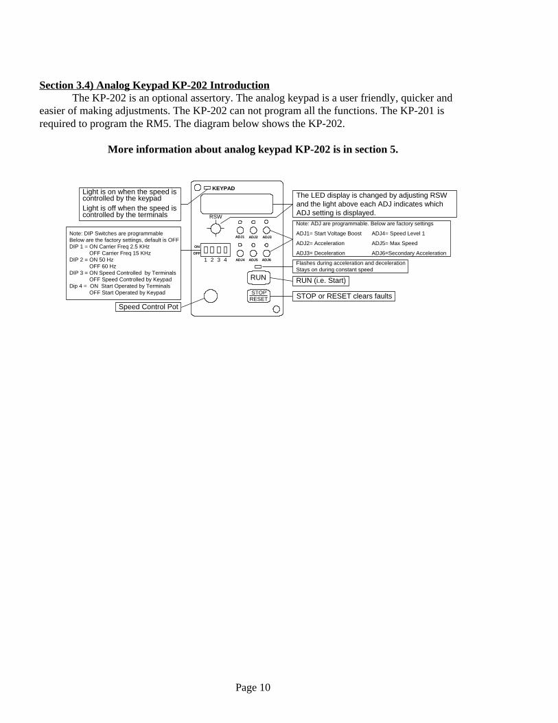
Section 4-1) Quick Set UpThis section covers the primary settings for typical applications. The RM5 factory default settings
are to operated from the KP-101 digital key pad. The typical user wants to connect to the terminalsauxiliary Start, Stop and Speed Pot and program the Acceleration and Deceleration time.
To program Start (Run) to operate from the terminals see F 001 in the table below. If F001 is set to 0 or 1, the RM5 will stop if the auxiliary start circuit is opened or the Stop/Reset key ispushed. To disable the keypad stop key, see F 003. If the user wants the motor to coast to a stop(uncontrolled deceleration) see F082.
Accelerate and Decelerate time are easily program by F 019 and F 020. The user is required to program the Motor’s Ratings into the RM5. See the motor’s name plate for
the motor’s ratings. The RM5 is programed at the factory for a typical AC motor. The user shouldprogram the RM5 for the following parameters. The motor’s Maximum Current, No Load Current (ifavailable on the name plate), Voltage (depending on how the motor is wired) and the Number of Poles.
Most user’s will be interested in features such as;Energy Economy, reduces the voltage to the minimum required to maintain speed (F 102)Key pad default display (F 006)Motor over current switch off response time, standard or fast (F 047).
Note: Measuring the output voltage must be made with a true RMS digital meter or analog meter
1) Enable Energy Economy, Reduces Voltage to minimum to maintain speed0) Disable Energy Economy, Factory set: 0
Energy EconomyF 102
1) Uncontrolled Deceleration Stop (coast to stop) 0) Controlled Deceleration Stop
Stop DecelerationF 082
Setting the motor’s number of poles calibrates the RPM and the Userdefined meter (See F007) . Select: 2P, 4P, 6P, 8P, 10P. Factory set: 4PNumber of PolesF 051
See data on motor’s name plate for no load current rating.If not available on name plate measure the current. Factory set: 0.1
Motor’s No Load Current RatingF 049
See motor's name plate for the maximum current ratingMotor’s Maximum Current RatingF 048
1) Fast switch off time0) Standard switch off time. Factory set : 0Over Current
Switch OffF 047
0 to 3200 sec. Factory set: (1/2to5 Hp, 5 sec)(7.5to30 Hp, 15 sec)(40Hp&up, 30 sec)Deceleration TimeF 0200 to 3200 sec. Factory set: (1/2 to 5 Hp 5 sec)(7.5to30 Hp)(15 sec,40Hp&up, 30 sec)Acceleration TimeF 019
This setting overrides all others.Factory set: 60 HzMaximumFrequencyF 031
Factory set: 16) RPM3) Voltage8) Terminal Status5) Current2) Hz Setting7) Custom Speed Meter4) DC Supply Voltage1) Hz Output
Keypad Default DisplayF 006
1) Enable Keypad Stop, Factory set: 10) Disable Keypad StopKeypad StopF 003
3) Keypad Arrow Keys with user defined meter displayed when arrow keys are pressed. (See F007)
2) Keypad Arrow Keys with RPM display when arrow keys are pressed.1) Keypad Arrow Keys with Hz display. Factory set: 10) Speed Pot Terminals: 12V, Vin, GND or Current Ref.., Iin, GND
Speed ControlF 002
Notes: Settings: 0, 1, 2. If FWD, COM or REV, COM are not connected the keypad display flashes, - - - - - . If both FWD, REV are connected to COM the keypad display flashes, def.
3) Keypad Start, Terminals activate Forward only. Factory set: 32) Keypad Start, Terminals activate Forward or Reverse.1) Terminals activate Forward & Start.0) Terminals activate Forward & Start or Reverse & Start.
Start, Forward & ReverseF 001
Section 4) Programming Instructions
Page 11

Section 4.2) Maximum Frequency Programming The output frequency of the RM5 will not exceed the frequency setting of F 031. Otherfrequency scales can be set greater than F 031 for scaling purposes.
This setting overrides all others.0.1 to 400 Hz Factory set: 60 Hz
Maximum FrequencyAnd
Master Freq., ReferenceF 031
Section 4.3) Multiple Speed Levels Activation and Frequency Settings.The RM5 has a Main Speed plus 7 speed levels and jog. The speed levels 1 through 7 can beprogrammed to be active by inputs X1, X2, X3 in binary order. Input X3 is factory set to Jog.To change X3 to operate according to the table below. F 054 must be set to 5. See section 4.6The settings of F 009 through F 017 will be overridden by F 031 setting. See Section 4.4
Frequency Setting and Terminal Activation Table
0 to 400 Hz, Factory set: 6 Hz, X3 is factory to Jog (F054 set 1)JogF017OnOnOn*0 to 400 Hz, Factory set: 0 HzSpeed Level 7F 016OffOnOn*0 to 400 Hz, Factory set: 0 HzSpeed Level 6F 015OnOffOn*0 to 400 Hz, Factory set: 0 HzSpeed Level 5F 014OffOffOn*0 to 400 Hz, Factory set: 0 HzSpeed Level 4F 013OnOnOff0 to 400 Hz, Factory set: 0 HzSpeed Level 3F 012OffOnOff0 to 400 Hz, Factory set: 20 HzSpeed Level 2F 011OnOffOff0 to 400 Hz, Factory set: 10 HzSpeed Level 1F 010OffOffOff0 to 400 Hz, Factory set: 60 HzMain Speed F 009X1X2X3*Note* Levels 4,5,6,7 are only activated when F054 is set to 5Terminals
Section 4.4) Input Terminal Programming: X1 through X6Terminals X1 through X6 can be custom programmed to the 12 functions in the table below.
Input Terminal Table
12) Disable accel & decel6) ResetFactory set: 6X6 Terminal InputF 05711) Resume Speed Ref. Setting5) Multi Speed Level 3Factory set: 7X5 Terminal InputF 05610) Resume Programmed Speed4) Multi Speed Level 2Factory set: 2X4 Terminal InputF 0559) Stop3) Multi Speed Level 1Factory set: 1X3 Terminal InputF 0548) Disable Outputs Y1, Y2, Ta, Tb.2) Secondary Accel & DecelFactory set: 4X2 Terminal InputF 0537) External fault signal input.1) JogFactory set: 3X1 Terminal InputF 052
Section 4.5) Output Terminals Programming: Y1, Y2 and Ta, TbTerminals Y1 & Y2 are opto-isolated transistor collector outputs with common emitters (CME).Terminal Ta, Tb and Tc are a single pole double through (SPDT) relay with Tc the pole.
Output Terminal Table
6) Stall Prevention Detect
11) General fault detect5) Overload DetectFactory set: 11Relay Ta, Tb, Tc
TerminalsF 060
10) Restart after fault detect4) Frequency Output Detect
9) Ride-through Detect3) Zero Output Voltage Detect Factory set: 2Y2 Terminal OutputF 059
8) Braking2) Level Speed Detect
7) Low input voltage1) Output Voltage DetectFactory set: 1Y1 Terminal OutputF 058
Page 12

Section 4.6a) Acceleration & Deceleration Frequency Scale (F 018) Acceleration & deceleration are dependent on the frequency scale set by F 018. Example: If F 018 frequency is set to 60 Hz., and F 019 is set to 15 seconds. The motor willreach 60 Hz in 15 sec. If F 018 is changed to 30 Hz. The motor will reach 60 Hz in 30 sec.Section 4.6b) Acceleration & Deceleration (F 019 through F 026)The acceleration and deceleration time of the Main speed level plus speed levels 4, 5, 6, 7 andJog are all programmed by setting F 019 and F 020. Speed levels 1, 2 and 3 acceleration anddeceleration times are programmed independently by F 021 through F 026. Section 4.6c) Secondary Acceleration & Deceleration (F 027 & F028) The secondary acceleration and deceleration will override all other settings when input X4 isactivated. Secondary acceleration & deceleration are programmed by F 0 27 and F 028. Note:F055 must be set to 2 for X4 to activate secondary acceleration. See Section 4.6
Acceleration & Deceleration Table
0.1 to 3200 Sec., Factory set: 15 sec., Activated by input X4Note: F 055 must be set to 2 for X4 to activate secondary acceleration.Secondary Decel TimeF 028
0.1 to 3200 Sec., Factory set: 15 sec., Activated by input X4Note: F 055 must be set to 2 for X4 to activate secondary acceleration.
Secondary Accel TimeF 027
Factory set: (1/2 to 5 Hp: 5 sec)(7.5 to 30 Hp: 15 sec) (40 Hp & up: 30 sec)0.1 to 3200 Sec.,Speed Level 3
Deceleration TimeF 026
Factory set: (1/2 to 5 Hp: 5 sec)(7.5 to 30 Hp: 15 sec) (40 Hp & up: 30 sec)0.1 to 3200 Sec.,Speed Level 3
Acceleration TimeF 025
Factory set: (1/2 to 5 Hp: 5 sec) (7.5 to 30 Hp: 15 sec) (40 Hp & up: 30 sec)0.1 to 3200 Sec.,Speed Level 2
Deceleration TimeF 024
Factory set: (1/2 to 5 Hp: 5 sec) (7.5 to 30 Hp: 15 sec) (40 Hp & up: 30 sec)0.1 to 3200 Sec.,Speed Level 2
Acceleration TimeF 023
Factory set: (1/2 to 5 Hp: 5 sec) (7.5 to 30 Hp: 15 sec) (40 Hp & up: 30 sec)0.1 to 3200 Sec.,Speed Level 1
Deceleration TimeF 022
Factory set: (1/2 to 5 Hp: 5 sec) (7.5 to 30 Hp: 15 sec) (40 Hp & up: 30 sec)0.1 to 3200 Sec.,Speed Level 1
Acceleration TimeF 021
Factory set: (1/2 to 5 Hp: 5 sec) (7.5 to 30 Hp: 15 sec) (40 Hp & up: 30 sec)0.1 to 3200 Sec.,
Main Speed LevelDeceleration Time &
speed levels 4, 5,6, 7 & JogF 020
Factory set: (1/2 to 5 Hp: 5 sec) (7.5 to 30 Hp: 15 sec) (40 Hp & up: 30 sec)0.1 to 3200 Sec.,
Main Speed LevelAcceleration Time &
speed levels 4, 5,6, 7 & JogF 019
If accel is set at 15 sec., and frequency scale is 60 Hz.The motor will reach 60 Hz in 15 sec. If the frequencyscale is changed to 30 Hz. The motor will reach 60 Hzin 30 sec.
0.1 to 400 Hz Factory set: 60 Hz
Accel & DecelFrequency ScaleF 018
Section 4.6d) S-curve Starting, Leveling and StoppingThe s-curve time is in addition to the primary acceleration and deceleration times. Example: Ifthe s-curve time is programmed to 4 seconds and the primary acceleration time is 10 seconds andprimary deceleration time is 5 seconds. The over all acceleration time is 14 seconds anddeceleration time is 9 seconds
0 to 5 seconds. Factory set: 5 secS-curve Accel & Decel timeF 029
Page 13

Section 4.7) Speed Reference Scale (i.e. Speed Pot Voltage Scale)The RM5 is factory set for the arrow keys to adjust the speed. To change the speed reference to aspeed pot (VREF) connected to terminals Vin and GND set F 002 to 0. The factory default scaleof VREF is 0 to 10V. If terminal 12V is used, a dropping resistor is required (see wiring diagram).Current reference ( IREF ) use’s terminals Iin and GND. The factory default scale of Iref is 4 to 20mA.
The minimum value of the speed reference scale can beincreased. Example: (-0.2x10 = 2) the scale is 2 to 10 Volts
-1 to 1 ratio Factory set: 0
Analog Speed Ref.Scale MinimumF 041
The speed reference voltage scale is 0 to 10V and thecurrent scale is 4 to 20 mA. The maximum value can bereduced. Example: (10/1.25=8) the scale is 0 to 8 V
0.00 to 2 ratioFactory set: 1
Analog Speed Ref.Scale MaximumF 040
3) Arrow keys with linear speed display when arrow keys are pressed.2) Arrow keys with RPM display when arrow keys are pressed.1) Arrow keys with Hz display. Factory set: 10) Speed Pot Terminals: 12V, Vin, GND or Current Ref.., Iin, GND
Speed ControlF 002
Section 4.9) Operating Speed RangeThe operating speed range is factory set, 0 to 60 Hz. The speed range can be programmed to anyrange between 0 and 60 Hz. If for example you want the speed range to be 30 to 45 Hz. Followthe instructions in F042 and F043. If the settings are programed as in the example, The speed canonly be adjusted between 30 to 45 Hz. When the motor is started and the speed reference is set atminimum, the motor will accelerate to 30 Hz. When the speed reference is set to maximum themotor will go to 45 Hz (See the graph below).
F 043 is a ratio of F 031. Example: If F 031 is 60 Hzand F 043 is 0.5 the minimum frequency will be 30 Hz(0.5 x 60 = 30).
0.00 to 1 ratioFactory set 0
Frequency OperatingRange, MinimumF 043
F 042 is a ratio of F 031. Example: If F 031 is 60 Hzand F 041 is 0.75 the maximum frequency will be 45Hz (0.75 x 60 = 45).
0.00 to 1 ratioFactory set 0
Frequency Operating Range, MaximumF 042
Factory set 60 Hz This setting overrides all others0.1 to 400 HzMaximum OutputFrequencyF 031
Electric Regulator Corp., RM5 AC Control, Section 4 Programming Instructions
Page 14
10
20
30
40
50
60
HZ
Time
Min Speed 30 Hz
Max Speed 45 Hz

Section 4.10) Frequency Bypass Frequency bypass prevents the RM5’s speed from being set with in the bypass bandwidth. Themotor will quickly pass through the bypass bandwidth and will not level to a speed with in thebypass bandwidth.
The bandwidth applies to frequency skips 1, 2 and 3. Application example: To bypass 30 to 40 Hz. Set F 084 to 35 Hz and F087 to 5 Hz.
Frequency BypassBandwidthF 087
0 to 400 Hz Factory set: 0Frequency Bypass 3F 0860 to 400 Hz Factory set: 0Frequency Bypass 2F 0850 to 400 Hz Factory set: 0Frequency Bypass 1F 084
Section 4.11) Keypad Default DisplayThe keypad LED default display can be programmed to one of the eight functions below.
Factory set: 16) RPM3) Voltage8) Terminal Status5) Current2) Hz Setting7) User Defined Meter4) PN Voltage1) Hz OutputKeypad
Default DisplayF 006
Section 4.12) User Defined Meter (i.e. MPM) and RPM CalibrationCustom speed calibration is for user defined units of measure. The custom speed can be displayon the keypad LED (F 006 set 7) or a digital meter. See Section 4.15 Digital MeterProgramming.
Required for calibrating RPM and LinearSpeed
2 to 10 PolesFactory set: 4P
Number of Motor PolesF 051
3) Three Decimal Points1) One Decimal Point
2) Two Decimal Points0) No Decimal PointsFactory set: 0Keypad's Custom
Speed Decimal PointF 008
Example: 20 units per Hz is 1200 at 60 Hz.0 to 500 Units per Hz.Factory set: 20
Custom SpeedCalibrationF 007
Page 15
10
20
30
40
50
60
HZ
Time
40 Hz
30 HzBypass Bandwidth
The speed will not level in the bypass bandwith
If programmed as in example F 087, the speed will not level between 30 and 40 Hz.
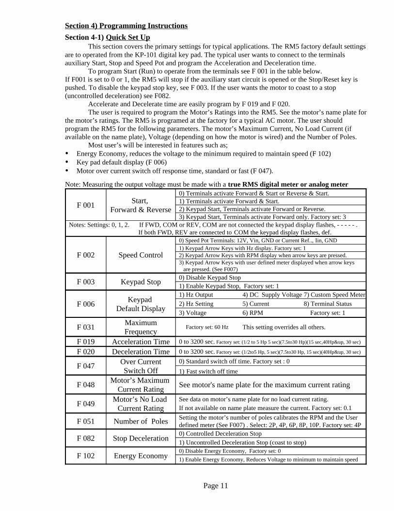
Section 4.13 Analog Meter Programming: Terminals FM+ and FM- (alternat GND)Meters are available from Electric Regulator. Please contact the factory.
0.01 to 2.00 Factory set: 1.00Analog Meter GainF 0452) Current1) Speed Reference setting.0) Output Frequency, Factory set: 0Analog Meter
Output of FM+F 044
Signal: 0 ~ 10 VoltsRL(MIN) 10 kIMAX 100 A
Section 4.14a) Digital Meter ProgrammingDigital meters and CN1 plug are available from Electric Regulator, please contact the factory.
8) Terminal Speed5) Current2) Set Speed, HzFactory set: 3Digital Meter 3F 1017) Custom Speed4) PN Voltage1) HzFactory set: 2Digital Meter 2F 1006) RPM3) Voltage0) NoneFactory set: 1Digital Meter 1F 099
0 to 3 Digital MetersFactory set: 0Number of Digital MetersF 098
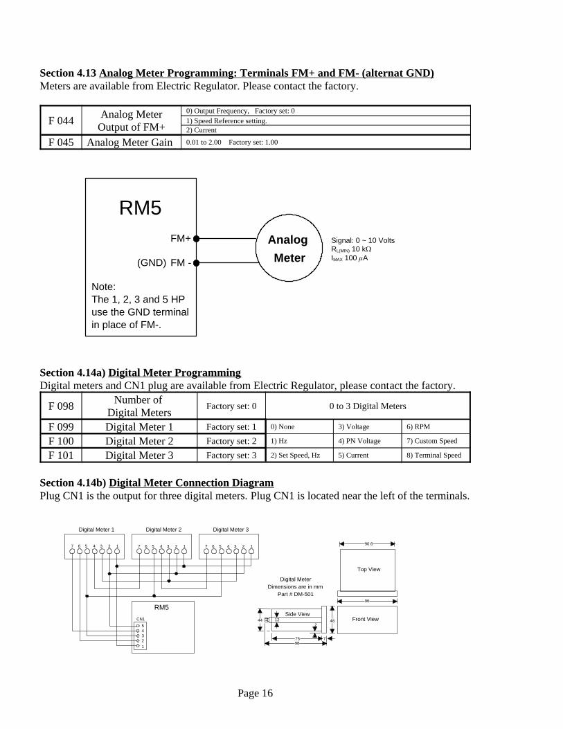
Section 4.14b) Digital Meter Connection DiagramPlug CN1 is the output for three digital meters. Plug CN1 is located near the left of the terminals.
Page 16
RM5FM+
FM - (GND)
AnalogMeter
Note:The 1, 2, 3 and 5 HPuse the GND terminalin place of FM-.
12345
RM5
7 6 5 4 3 2 1 7 6 5 4 3 2 1 7 6 5 4 3 2 1
CN1
Digital Meter 1 Digital Meter 2 Digital Meter 3
122
798
44
75
96
48
90.6
Top View
Front ViewSide View
Digital Meter
Part # DM-501Dimensions are in mm
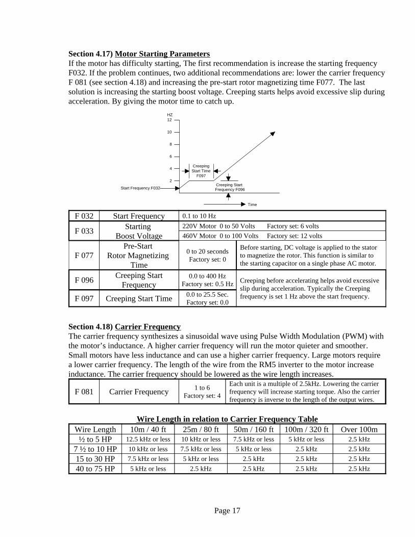
Section 4.17) Motor Starting ParametersIf the motor has difficulty starting, The first recommendation is increase the starting frequencyF032. If the problem continues, two additional recommendations are: lower the carrier frequencyF 081 (see section 4.18) and increasing the pre-start rotor magnetizing time F077. The lastsolution is increasing the starting boost voltage. Creeping starts helps avoid excessive slip duringacceleration. By giving the motor time to catch up.
0.0 to 25.5 Sec.Factory set: 0.0Creeping Start TimeF 097
Creeping before accelerating helps avoid excessiveslip during acceleration. Typically the Creepingfrequency is set 1 Hz above the start frequency.
0.0 to 400 HzFactory set: 0.5 Hz
Creeping StartFrequencyF 096
Before starting, DC voltage is applied to the statorto magnetize the rotor. This function is similar tothe starting capacitor on a single phase AC motor.
0 to 20 secondsFactory set: 0
Pre-Start Rotor Magnetizing
TimeF 077
460V Motor 0 to 100 Volts Factory set: 12 volts220V Motor 0 to 50 Volts Factory set: 6 voltsStarting
Boost VoltageF 033
0.1 to 10 HzStart FrequencyF 032
Section 4.18) Carrier FrequencyThe carrier frequency synthesizes a sinusoidal wave using Pulse Width Modulation (PWM) withthe motor’s inductance. A higher carrier frequency will run the motor quieter and smoother.Small motors have less inductance and can use a higher carrier frequency. Large motors requirea lower carrier frequency. The length of the wire from the RM5 inverter to the motor increaseinductance. The carrier frequency should be lowered as the wire length increases.
Each unit is a multiple of 2.5kHz. Lowering the carrierfrequency will increase starting torque. Also the carrierfrequency is inverse to the length of the output wires.
1 to 6Factory set: 4Carrier FrequencyF 081
Wire Length in relation to Carrier Frequency Table
2.5 kHz2.5 kHz2.5 kHz2.5 kHz5 kHz or less40 to 75 HP2.5 kHz2.5 kHz2.5 kHz5 kHz or less7.5 kHz or less15 to 30 HP2.5 kHz2.5 kHz5 kHz or less7.5 kHz or less10 kHz or less7 ½ to 10 HP2.5 kHz5 kHz or less7.5 kHz or less10 kHz or less12.5 kHz or less½ to 5 HP
Over 100m100m / 320 ft50m / 160 ft25m / 80 ft10m / 40 ftWire Length
Page 17
HZ
Time
2
4
6
8
10
12
CreepingStart Time
F097
Creeping Start Frequency F096Start Frequency F032

Section 4.19) Motor Ratings and Overload ParametersRead the motor’s name plate before programming this section.
When an overload exceeds the setting of F 068 and the timesetting of F 069 is exceeded, the RM5 will shut off. Note: F 069 does not sum the time of separate overload events.
0.1 to 10 seconds.Factory set: 0.1
Fast OverloadResponse TimeF 069
30% to 200% of the RM5 rated current. Factory set 160%Fast Overload LevelF 0681) Enable shut off when overload is detected.0) Disable shut off when overload is detected. Factory set: 0
Fast OverloadF 067
1) Signal overload when the motor is running at any speed.0) Signal overload only when the motor is running at the set speed. Overload Signal
ConditionsF 066
1) Enable Overload Signal
When outputs Y1, Y2 or relay T (i.e. F 058,F059 or F 060) are programmed to signal whenan overload is detected (i.e. 5). F 065 enablesor disables this output.
0) Disable Overload Signal Factory set: 0Overload SignalF 065
See motor’s name plate for no load current rating. If not listed on nameplate, measure the current. Factory set: 0.1
Motor's No LoadCurrent RatingF 049
See the motor's name plate for the current rating.Motor Current RatingF 048
Use when motor’s rating exceeds the RM5rating.1) RM5 inverter rating.
Use when motor rating is equal or less than theRM5 rating (See F 048).0) Motor rating. Factory set: 1Slow Overload
OptionsF 047
1) Enable slow overload protection. Factory set: 10) Disable slow overload protection
Slow OverloadF 046
Fast overload responds by switching off the motor when the current exceeds the setting of F068by more than the time setting of F069. Important: F067 disables and enables F068 and F069. Thefactory default settings are shown on the “Overload Graph” above. If at any speed the motorcurrent exceeds 160% for more than 0.1 second, the motor is switched off. Important note:F067 default setting is: Disable fast overload.
Slow overload curves can not be changed by the user. The OL curve overrides all other curves.Example: If at any speed the motor current exceeds 150% for more than one minute the motor isswitched off. Second example: If the motor is running at 20 Hz and the motor current exceeds95% for more than 15 minutes, the motor is switched off.
Page 18
200%
180%
160%
140%
120%
100%
80%
60%
40%
20%
0%
0 1 2 3 4 5 6 7 8 9 10 11 12 13 14 15 16 17 18 19 20Minutes
40 Hz60 Hz
20 Hz10 Hz
5 Hz
OL
(see F047)Overload Graph
F 068 set: 160%Fast overload current
Slow overload curves
Fast overload time (F 069 set 0.1 seconds)Fast overload trip piont
CurrentRating
Note: OL overidesall othercurves

Section 4.20) Motor Slip and Stall Parameters
30% to 200% of the RM5 inverter’s rated current.Factory set: 150%
Level Speed Tracking CurrentF 088
1) Enable stall prevention during deceleration. Factory set: 10) Disable stall prevention during decel. If dynamic braking is used F 074 can be disabled.Deceleration Stall
Prevention F 074
Deceleration time after recovery from stall, duringdeceleration.
0.1 to 3200 secFactory set: 15 sec
Deceleration StallRecovery Deceleration TimeF 073
Acceleration time after recovery from stall , during levelspeed.
0.1 to 3200 secFactory set: 15 sec
Level Speed Stall RecoveryAcceleration TimeF 072
30% to 200% of the motor's rated current (F 048) before the speed is leveled.Factory set: 160%.
Acceleration Stall PreventionF 071
30% to 200% of the motor's rated current (F 048) before the speed is reduced.Factory set: 170%.
Level Speed Stall PreventionF 070
F050 = LC−F049F048−F049
F050= Motor Slip CompensationF049= Motor No load CurrentF048= Motor Max. Rated Current LC = Load Current (during normal operation)
-9.9 to 5 HzFactory set: 0.0
Motor SlipCompensationF 050
Section 4.21) Level Speed Detection SignalLevel speed detection signal is enabled when F058, F059 or F060 are set to 2. Then activatingoutputs Y1, Y2 or relay T (see section 4.7). If the operator wants the signal activated before thecontrol reaches level speed. The level speed detection bandwidth can be set by F061, F062 orF063.
If 400 Hz operation is enabled (When F092 is set 3 or 4) (see section 4.2)
0 to 400 HzFactory set: 0 Hz
Level Speed Detect SignalFrequency Bandwidth
400 Hz operationF 063
This bandwidth sets the frequency were the output signalis activated. When the speed is controlled by arrow keys.(Output signals, when any of F058, F059, F060 are set 2.See section 4.7)(Arrowkey speed control, see F002)
0.0 to 10 Hz.Factory set: 2 Hz.
Level Speed Detect SignalFrequency Bandwidthfor Programmed Speed
(Arrowkey Speed Control)F 062
This bandwidth sets the frequency when the outputsignal is activated. When the speed is controlled byanalog signal, typically a manual speed pot connected toterminals. (Output signals, When any of F058, F059,F060 are set 2. See section 4.7) (Analog speed control,see F002 and section 4.9)
0.0 to 10 Hz.Factory set: 2 Hz.
Level Speed Detect SignalFrequency Bandwidthfor Speed Ref., Setting(Analog Speed Control)
F 061
Page 19
HZ
Time
10
20
30
40
50
60
F074 enabled, slip is held within parametersF074 disabled, excessive slip is permittedDynamic braking permits disabling of F074
DecelerationAcceleration
Inside the band current is limited to F088
Level SpeedIf the setting of F070 is exceeded the speed will be reduced
Speed Tracking Current
If F071 is exceeded, acceleration is slowed down
HZ
Time
10
20
30
40
50
60
Example of F062 Example of 061
F062 is set 10 HzThe arrowkeys are set to 60 HzThe signal will activate at 50 Hz
Lower Side Bandwidth
Frequency Bandwidth
F061 is set 2 HzThe analog speed is first set to 40 HzThe signal will activate at 38 HzThe analog speed is secondly set to 60 HzThe signal will deactiivate and reactivate at 58 Hz.
Signal Activation FrequencySignal Activation Frequency
Signal Activation Frequency
Frequency Bandwidth

Section 4.22) Voltage Frequency Patterns (V/F Patterns)The RM5 has three V/F patterns, the 1st, 2nd and Main V/F pattern. The factory settings usesonly the main V/F pattern. The 1st and 2nd patterns can be added by the programmer.
0.1 to 510 Volts, Factory set: 0 Volts460V Motor0.1 to 255 Volts, Factory set: 0 Volts220V Motor2nd V/F Pattern
Maximum VoltageF 039
F038 sets the frequency when F039 voltage is reached.If F038 is set to zero the 2nd V/F pattern is disabled.
0.01 to 400 HzFactory set: 0 HZ
2nd V/F PatternFrequency ScaleF 038
0.1 to 510 Volts, Factory set: 0 Volts460V Motor0.1 to 255 Volts, Factory set: 0 Volts220V Motor1st V/F Pattern
Maximum VoltageF 037
The V/F pattern can be customized into three sections,1st, 2nd and Main V/F patterns. F036 sets the frequencywhen F037 voltage is reached. If F036 is set to zero the1st V/F pattern is disabled. Note: When the 1st V/Fpattern is used, set F036 higher than F032.
0.01 to 400 HzFactory set: 0 HZ
1st V/F PatternFrequency ScaleF 036
0.1 to 510 Volts, Factory set: 380 or 460 Volts460V Motor0.1 to 255 Volts, Factory set: 220 Volts220V MotorMain V/F Pattern
Maximum VoltageF 035
The main frequency scale (F034) is the frequency wherethe maximum voltage is reached. Example: If F034 is 60Hz and F035 is 220V. Then at 60 HZ the voltage is220V. Second Example: If F034 is 120Hz and F035 isF036 220V then at 60Hz the voltage is 110V.
0.01 to 400 HzFactory set: 60 HZ
Main V/F PatternFrequency ScaleF 034
Examples of V/F PatternsLinear V/F pattern is the RM5’s default program. Squared Curve is for variable torque applications such as fans and pumps. Example: When thespeed of a fan doubles the torque load increases by square (x2 ). Center Winding Curve is for constant torque applications. Example: Center winding a roll of paperat constant linear speed. As the diameter and weight of the paper roll increases, the motor’s speeddecreases and the torque load increase. The parameters of an expanded curve must be determined bythe user. Keep in mind with AC motors with a constant torque load , if the voltage is decreased thecurrent will increase.
Page 20
50
100
150
200
250
Volts
50
100
150
200
250
Volts
010 3020 40 50 60 Hz
1st & 2nd V/F Patterns are DisabledF036 set 0F037 set 0F038 set 0F039 set 0
Main V/F Pattern
F035 set 220VF034 set 60Hz
10 3020 40 50 60 Hz0
1st V/F Pattern
F037 set 100VF036 set 20 Hz
2nd V/F Pattern
F039 set 150VF038 set 35 Hz
Main V/F PatternF035 set 220VF034 set 60 Hz
Factory Default V/F Pattern Example of user defined V/F Pattern
Examples of Linear, Squared Curve and Expanded Curve V/F Patterns
50
100
150
200
250220 Volt Motor
10 3020 40 50 60 Hz0
500
400
300
200
100Squared Curve
LinearCenter W
inder Curve
460 Volt Motor
460V motor F038:30Hz, F039: 115V220V motor F038: 30Hz, F039: 55V
460V motor F036:15Hz, F037: 29V220V motor F036:15Hz, F035: 11V
460V motor F034: 60Hz, F035: 460V220V motor F034: 60Hz, F035: 220V

Section 4.23) Power Interruption Ride-throughPower interruption is when the power goes off or the voltage goes below F 079 setting. If thepower is interrupted the response is selected by F 078. Ride-through allows the to restart if thepower is goes on in set time of F 089. For controlled stop programming see section 4.24
RM5-4*** 340V to 460V Factory set: 460VRM5-2*** 190V to 240V Factory set: 220VInput Voltage
CalibrationF 095
This sets the time limit the power can be interrupted andride-through will restart. If this time is exceeded the RM5will remain off. (Note: F 078 must be set to 1)
0.5 to 5 sec. Factory set: 0.5
Power InterruptionRide-through
Restart Time LimitF 089
460V Motor: 230V to 384V, Factory set 330V220V Motor: 130V to 192V, Factory set 175VPower Interruption
Switch Point VoltageF 079
3) Enable Controlled Deceleration Stop when power is interrupted.2) Shut Off1) Enable Ride-through (see F 089)0) Disable Ride-through Factory set: 0
Power InterruptionResponseF 078
Section 4.24) Power Interruption Controlled Stop ProgramIf power is interrupted the factory settings are to let the motor coast to a stop. If controlled stopis required, F078 set to 3 will enable controlled stop. The deceleration curve can be defined byfunction codes F103, F104, F105, F106.
This frequency is the point when the 1st decel timeswitches to the 2nd decel time. If F 106 is set 0 Hz,the 2nd decel time is disabled.
0 to 400 HzFactory set: 0
Switch Point Frequencyfrom
1st to 2nd decel timeF 106
If F 106 is set 0 Hz F 105 is inactive. If F 106 is set30 Hz and F 105 is set 15 sec., the motor will decelfrom 30 Hz to stop in 15 sec.
0 to 3200 secFactory set: 15
2nd Decel Timefrom F 106 to stopF 105
If F 106 is set 0 Hz and F 104 is set 15 sec., themotor will decel to a stop in 15 sec. If F 106 is set 30Hz the motor will decel to 30 Hz in 15 sec.
0 to 3200 secFactory set: 15
1st Decel Time from F 103 to F 106F 104
When the power is interrupted the frequency will immediately bereduced by this setting. A large decrease will cause hard braking.Example: The motor is running at 60 Hz and F 103 is set 3 Hz.When the power is shut off, the output frequency immediately bereduced to 57 Hz (60 - 3 = 57).
0 to 20 HzFactory set: 3
Power InterruptionFrequency ReductionF 103
460V Motor: 230V to 384V, Factory set 330V220V Motor: 130V to 192V, Factory set 175VPower Interruption
Voltage Switch PointF 079
3) Enable Controlled Deceleration Stop when power is interrupted.2) Shut Off (Uncontrolled Stop, Coast to Stop)1) Enable Ride-through0) Disable Ride-through Factory set: 0
Power InterruptionResponseF 078
Page 21
5 10 15 20 25 30
10
30
40
50
60
20
Hz
Time0 5 10 15 20 25 30
10
30
40
50
60
20
Hz
Time0 5 10 15 20 25 30
10
30
40
50
60
20
Hz
Time0 5 10 15 20 25 30
10
30
40
50
60
20
Hz
Time0 5 10 15 20 25 30
10
30
40
50
60
20
Hz
Time0 5 10 15 20 25 30
10
30
40
50
60
20
Hz
Time0 5 10 15 20 25 30
10
30
40
50
60
20
Hz
Time0 5 10 15 20 25 30
10
30
40
50
60
20
Hz
Time0 5 10 15 20 25 30
10
30
40
50
60
20
Hz
Time0 5 10 15 20 25 30
10
30
40
50
60
20
Hz
Time0 5 10 15 20 25 30
10
30
40
50
60
20
Hz
Time0 5 10 15 20 25 30
10
30
40
50
60
20
Hz
Time0 5 10 15 20 25 30
10
30
40
50
60
20
Hz
Time0 5 10 15 20 25 30
10
30
40
50
60
20
Hz
Time0 5 10 15 20 25 30
10
30
40
50
60
20
Hz
Time0 5 10 15 20 25 30
10
30
40
50
60
20
Hz
Time0
Factory set power off stop Example of user defined power off stop
F104set: 15 sec
F103set: 3 Hz
Time of Power Interuption
F105 set: 15 secF106 set: 0 HzNote: Because F106 is set 0 Hz F105 is disabled
Time of Power Interuption
F103set: 3 Hz
F104set
5 sec
F105set: 15 sec
F106 set: 30 Hz

Section 4.25) DC Braking (i.e. Dynamic Braking, DB )The RM5 will handle up to 50% of the motor’s regenerative current without a dynamic braking resistor. Ifthe motor’s regenerative current exceeds 50%, a Dynamic Braking is required. The RM5 units rated from½ to 5 Hp has a internal Dynamic Braking Transistor (DBT) as a standard feature. The RM5 from 7 ½ HPand higher require a external Dynamic Braking Unit (DBU), available at additional charge. If thecustomer requires the DBU (i.e. DBT) installed internally. It is available at additional charge and 4 weeksdelivery time. The regenerative current created by the motor is determined by the motor’s inertia, theload’s inertia, the deceleration time and friction. The current rating of the DBU must be determined by theapplication engineer. If the current exceeds the rating of one DBU, additional DBUs can be connected inparallel (i.e. Master / Slave).
Instructions for ½ to 5 HPImportant, codes F075 and F077 only apply to ½ to 5 HP models or RM5 with the internal DBU installed.They don’t apply to the external DBU5.
This allows the DB resistor time to cool.0 to 20 Sec.Factory set: 0.5
Time Delay beforeRestart after DC
BrakingF 076
0 to 150% of the RM5 current rating. Factory set: 50%DC Braking CurrentF 075
Instructions for external DBUWhen the external DBU isinstalled, disable AVR.
0) Disable AVR1) Enable AVR (Factory set 1)
Automatic VoltageRegulation (AVR)F 093
Four external DBU units are available.Part # DBU5-L50 Rating: 230VAC, 50A Part # DBU5-H50 Rating: 460VAC, 50APart # DBU5-L75 Rating: 230VAC, 75A Part # DBU5-H75 Rating: 460VAC, 75A
Page 22
P PRPE WVUTSR
3 PHASE
RM5
DB resistor
MOTOR
1/2 to 5 HP
230 VACor
460 VAC
N(-)
P(+)
N P BR1 BR2
380V
400V
415V
440V
460V
480V
SLA
VE
JP1
JP2
N P BR1 BR2
380V
400V
415V
440V
460V
480V
SLA
VE
JP1
MO-
MO+
SI-
SI+TA TC
DB resistor
N P BR1 BR2
380V
400V
415V
440V
460V
480V
SLA
VE
JP1
JP2
N P BR1 BR2
380V
400V
415V
440V
460V
480V
SLA
VE
JP1
MO-
MO+
SI-
SI+TA TC
DB resistor
MA
STE
R
MA
STE
R
WARNING: correct installation of the externial DBU5 is critical. A wiring error will result in catastrophic failure of the DBU5 and RM5. Take extra care to be certian the wiring is correct.
PR PEWVUTSR
MOTOR
460VAC3 PHASE
no jumper is reqiured15 HP and higherthe jumper is required.
JUMPER
RM5
7 to 10 HP
Master SlaveThis example is the DBU5-HThe jumpers are set:
The jumpers are set
JP1 = 460VJP1 = 460VJP2 = SLAVE
JP2 = MASTER
7 HP and higher
Use twisted pairor shielded wire.
WARNING: If JP1 is set too low, the DBU5 will be on continuously, causing the the unit to fail
TA and TC are terminals for the fault signal relay

Dynamic Brake Resistor (DB resistor)The application engineer must determine the amount of current generated by the deceleratingmotor. Then select the value of the DBU and DB resistor. Below is a table of typical resistorvalues for each model up to 30 HP.
MHL 500W-40Two in series
Four in parallelTotal eight pieces
20RM5-4030MHL 500W-40Six in parallel6.6RM5-2030
MHL 500W-40Two in series
Two in parallelTotal four pieces
40RM5-4020MHL 500W-40Four in parallel10RM5-2020
MHL 500W-40Two in series
Two in parallelTotal four pieces
40RM5-4015MHL 500W-40Three in parallel13.3RM5-2015
MHL 500W-40Two in series80RM5-4010MHL 500W-4020 to 40RM5-2010
MHL 500W-40Two in series80RM5-4007MHL 500W-4020 to 40RM5-2007
MHL 100W-400Four in parallel100RM5-4005MHL 500W-4040 RM5-2005
MHL 100W-400Three in parallel133RM5-4003MHL 500W-4040RM5-2003
MHL 100W-100100RM5-2002MHL 100W-400
Two in parallel200RM5-4002MHL 100W-100100RM5-2001
MHL 100W-400400RM5-4001MHL 100W-100100RM5-200 ½
RecommendedResistor/s
TypicalresistanceModel #Recommended
Resistor/sTypical
resistanceModel #
0.42”/10.6mm1.97”/50mm3.9”/100mm15.16”/385mm15.75”/400mmMHL1000W-1000.42”/10.6mm1.97”/50mm3.9”/100mm15.16”/385mm15.75”/400mmMHL1000W-40
0.2”/5.3mm1.18”/30mm2.36”/60mm12.6”/320mm13.19”/335mmMHL500W-1000.2”/5.3mm1.18”/30mm2.36”/60mm12.6”/320mm13.19”/335mmMHL500W-400.2”/5.3mm1.18”/30mm2.36”/60mm9.85”/250mm10.43”/265mmMHL400W-4000.2”/5.3mm1.18”/30mm2.36”/60mm9.85”/250mm10.43”/265mmMHL400W-1000.2”/5.3mm1.18”/30mm2.36”/60mm7.9”/200mm8.46”/215mmMHL300W-4000.2”/5.3mm1.18”/30mm2.36”/60mm7.9”/200mm8.46”/215mmMHL300W-1000.2”/5.3mm1.18”/30mm2.36”/60mm5.9”/150mm6.5”/165mmMHL200W-4000.2”/5.3mm1.18”/30mm2.36”/60mm5.9”/150mm6.5”/165mmMHL200W-1000.2”/5.3mm0.79”/20mm1.57”/40mm7.9”/200mm8.46”/215mmMHL150W-4000.2”/5.3mm0.79”/20mm1.57”/40mm7.9”/200mm8.46”/215mmMHL150W-1000.2”/5.3mm0.79”/20mm1.57”/40mm6.9”/175mm7.5”/190mmMHL120W-4000.2”/5.3mm0.79”/20mm1.57”/40mm6.9”/175mm7.5”/190mmMHL120W-1000.2”/5.3mm0.79”/20mm1.57”/40mm5.9”/150mm6.5”/165mmMHL100W-4000.2”/5.3mm0.79”/20mm1.57”/40mm5.9”/150mm6.5”/165mmMHL100W-1000.2”/5.3mm0.79”/20mm1.57”/40mm4.9”/125mm5.5”/140mmMHL80W-4000.2”/5.3mm0.79”/20mm1.57”/40mm4.9”/125mm5.5”/140mmMHL80W-1000.2”/5.3mm0.79”/20mm1.57”/40mm3.9”/100mm4.5”/115mmMHL60W-4000.2”/5.3mm0.79”/20mm1.57”/40mm3.9”/100mm4.5”/115mmMHL60W-100
DHWL2L1 Dimensions in/mmPart Number
Page 23
L2
L1
W
H
D
Wire Lenth30 to 40 mm
Part Number Description: MHL 60W - 100
ResistanceWatts
Prefix
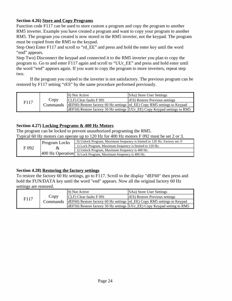
Section 4.26) Store and Copy ProgramsFunction code F117 can be used to store custom a program and copy the program to anotherRM5 inverter. Example you have created a program and want to copy your program to anotherRM5. The program you created is now stored in the RM5 inverter, not the keypad. The programmust be copied from the RM5 to the keypad. Step One) Enter F117 and scroll to “rd_EE” and press and hold the enter key until the word“end” appears. Step Two) Disconnect the keypad and connected it to the RM5 inverter you plan to copy theprogram to. Go to and enter F117 again and scroll to “UUr_EE” and press and hold enter untilthe word “end” appears again. If you want to copy the program to more inverters, repeat steptwo.
If the program you copied to the inverter is not satisfactory. The previous program can berestored by F117 setting “rES” by the same procedure performed previously.
UUr_EE) Copy Keypad settings to RM5dEF50) Restore factory 50 Hz settingsrd_EE) Copy RM5 settings to KeypaddEF60) Restore factory 60 Hz settingsrES) Restore Previous settingsCLF) Clear faults F 091SAu) Store User Settings0) Not Active
CopyCommandsF117
Section 4.27) Locking Programs & 400 Hz MotorsThe program can be locked to prevent unauthorized programing the RM5.Typical 60 Hz motors can operate up to 120 Hz for 400 Hz motors F 092 must be set 2 or 3.
3) Lock Program, Maximum frequency is 400 Hz.2) Unlock Program, Maximum frequency is 400 Hz.1) Lock Program, Maximum frequency is limited to 120 Hz.0) Unlock Program, Maximum frequency is limited to 120 Hz. Factory set: 0Program Locks
&400 Hz Operation
F 092
Section 4.28) Restoring the factory settingsTo restore the factory 60 Hz settings, go to F117. Scroll to the display "dEF60" then press andhold the FUN/DATA key until the word "end" appears. Now all the original factory 60 Hzsettings are restored.
UUr_EE) Copy Keypad setting to RM5dEF50) Restore factory 50 Hz settingsrd_EE) Copy RM5 settings to KeypaddEF60) Restore factory 60 Hz settingsrES) Restore Previous settingsCLF) Clear faults F 091SAu) Store User Settings0) Not Active
CopyCommandsF117
Page 24

Section 5) Analog Keypad (KP-202)Adjustments to the analog keypad (i.e. KP-202) are best made with a #00 Philips head screwdriver.
Section 5.1) KP-202 Factory SettingsThe diagram below shows the KP-202 layout and factory default settings.The KP-202 adjustment pots one through 6 (i.e. ADJ1 to 6) and dip switches function are shown inthe diagram below. The RSW switch selects the LED display mode. The functions of the pots anddip switches can be programmed, please see sections 5.3 and 5.4
Section 5.2 Rotary Switch (RSW) OperationThe RSW switch changes the LED display mode. See the table below for descriptions of eachposition of RSW. Positions 1 trough 6 display the program settings of ADJ 1 trough 6. All theother positions are not programmable (fixed).
NANot ProgrammableDIP StatusFNANot ProgrammableTerminal StatusENANot ProgrammableLinear SpeedDNANot ProgrammableMotor RPMCNANot ProgrammableCurrent OutputBNANot ProgrammablePN VoltageANANot ProgrammableVoltage Output9
F0811=2.5k Hz, 2 = 5kHz, 3 = 7.5kHz, 4 = 10kHz, 5 = 12.5kHz, 15kHzCarrier Frequency8NANot ProgrammableSpeed Control Pot setting7
F027, F028Secondary Acc & Dec Time, 0.0 to 165 secondsADJ 6 setting6F031Maximum Output Freq., 0.0 to 120 Hz ADJ 5 setting5F021Speed Level 1 Freq., 0.0 to 120 HzADJ 4 setting4F020Declaration Time, 0.0 to 165 secondsADJ 3 setting3F019Acceleration Time , 0.0 to 165 secondsADJ 2 setting2F033Start Boost Voltage, 0 to 127 VoltsADJ 1 setting1NANot ProgrammableFrequency Output (Hz)0
See CodeFactory Default SettingFunction DisplayedRSW Position
Page 25
KEYPAD
RUN (i.e. Start)
Light is on when the speed iscontrolled by the keypadLight is off when the speed is controlled by the terminals
RUN
STOPRESET
1 2 3 4
ON
OFF
RSW
ADJ1 ADJ2 ADJ3
ADJ4 ADJ5 ADJ6
STOP or RESET clears faults
The LED display is changed by adjusting RSW
Flashes during acceleration and decelerationStays on during constant speed
ADJ1= Start Voltage Boost
ADJ2= Acceleration
ADJ3= Deceleration
ADJ4= Speed Level 1
ADJ5= Max Speed
ADJ6=Secondary Acceleration
Speed Control Pot
Note: ADJ are programmable. Below are factory settings
Note: DIP Switches are programmableBelow are the factory settings, default is OFFDIP 1 = ON Carrier Freq 2.5 KHz
DIP 2 = ON 50 Hz
DIP 3 = ON Speed Controlled by Terminals OFF Speed Controlled by KeypadDip 4 = ON Start Operated by Terminals OFF Start Operated by Keypad
OFF Carrier Freq 15 KHz
OFF 60 Hz
and the light above each ADJ indicates whichADJ setting is displayed.

Section 5.3) Adjustment (ADJ) ProgrammingThe user can custom program the adjustments (ADJ) of the KP-202. Programming requires
disconnecting the KP-202 and connecting KP-201. Function codes F 107 through F 112 arereserved for programming ADJ 1 to 6. See table below.
1 to 47, factory set:17F 112ADJ 61 to 47, factory set:10F 109ADJ 31 to 47, factory set:20F 111ADJ 51 to 47, factory set: 9F 108ADJ 21 to 47, factory set: 1F 110ADJ 41 to 47, factory set:19F 107ADJ 1
SettingsFunction code
reserved to program adjustment
AdjustmentSettingsFunction code
reserved to program adjustment
Adjustment
Example, to program ADJ 1 to Main Acceleration Time. Go to F107 and select 9. To read moreinformation about Main Acceleration Time read F019 in the function code table.
Page 26
KEYPAD
RUN
STOPRESET
1 2 3 4
ON
OFF
RSW
ADJ1 ADJ2 ADJ3
ADJ4 ADJ5 ADJ6
KP-202
Adjustments
F0370.0 to the Volt.,setting of F 035
VF Pattern 1 Voltage.,Switch Point23
F0360.0 to the Freq.,setting of F 034
VF Pattern 1 Freq., Switch Point22
F0350 to 255/230V input0 to 510/460V inputMaximum Voltage21
F0310.0 to 120 HzMaximum Frequency20F0330 to 127 VoltsStart Voltage Boost19F0320.0 to 10 HzStart Frequency18
F0270.1 to 165 secSecondary Acc & Dec Time17
F0260.1 to 165 secSpeed Level 3 Dec Time16F0250.1 to 165 secSpeed Level 3 Acc Time15F0240.1 to 165 secSpeed Level 2 Dec Time14F0230.1 to 165 secSpeed Level 2 Acc Time13F0220.1 to 165 secSpeed Level 1 Dec Time12F0210.1 to 165 secSpeed Level 1 Acc Time11F0200.1 to 165 secMain Deceleration Time10F0190.1 to 165 secMain Acceleration Time9F0170.0 to 120 HzJog Speed8F0160.0 to 120 HzSpeed Level 7 Hz7F0150.0 to 120 HzSpeed Level 6 Hz6F0140.0 to 120 HzSpeed Level 5 Hz5F0130.0 to 120 HzSpeed Level 4 Hz4F0120.0 to 120 HzSpeed Level 3 Hz3F0110.0 to 120 HzSpeed Level 2 Hz2F0100.0 to 120 HzSpeed Level 1 Hz1NANo FunctionDisable0
SeeCode
Range ofADJ settingFunction DescriptionSetting
F0070.01 to 100Speed Meter Calibration
Note: The resolution of the pot limits the scale to 100 units.
46
F0970.0 to 25 secCreeping Start Time45F0960.00 to F 031Creeping Start Freq.,44F0870.0 to 25.5 HzBypass Bandwidth43F0860.00 to F 0313rd Freq., Bypass42F0850.00 to F 0312nd Freq., Bypass41F0840.00 to F 0311st Freq., Bypass40F0750 to 150%DC Braking Current39F0730.0 to 165 SecStall Recovery Deceleration38F0720.0 to 165 SecStall Recovery Acceleration37
F07030 to 200%Stall Prevention during Level Speed36
F07130 to 200%Stall Prevention during Acceleration35
F06830 to 200%Overload of RM5 rating 34F0640.0 to 3.0Torque Boost33F0630.00 to F 031Level Speed Signal32F050-9.9 to 5.0Slip Compensation31
F0450.00 to 2.00FM+, FM- Analog Meter Gain30
F0430.00 to 1.00Minimum Speed29F0420.00 to 1.00Maximum Speed28F041-1.00 to 1.00Speed Ref., Scale Min.27F0400.00 to 2.00Speed Ref., Scale Max.26
F0390.0 to the Volt.,setting of F 035
VF Pattern 2 Voltage.,Switch Point25
F0380.0 to the Freq.,setting of F 034
VF Pattern 2 Freq., Switch Point24
SeeCode
Range ofADJ settingFunction DescriptionSetting

Section 5.4 DIP Switch ProgramingThe DIP switches enable or disable program functions. The user can custom program the DIPswitches of the KP-202. Programming requires disconnecting the KP-202 and connecting KP-201.Function codes F 113 through F 116 are reserved for programming DIP switches 1 to 4. See tablebelow.
0 to 15, factory set: 2F116DIP 40 to 15, factory set: 3F115DIP 30 to 15, factory set: 5F114DIP 20 to 15, factory set: 8F 113DIP 1
SettingsFunction code
reserved toprogram DIP
DIP #
Example, to program DIP switch 1 to Energy Economy go to F113 and select 15. To read moreinformation about Energy Economy read F102 in the function code table.
OFF: Disable Energy EconomyOFF: Enable DC braking* F102ON: Enable Energy Economy
15F075ON: Disable DC braking*
7
OFF: Enable inverter overload protectionOFF: Enable Stall prevention during accel. F094ON: Disable inverter overload protection
14F074ON: Disable Stall prevention during accel
6
OFF: Enable F046 overload programOFF: Maximum frequency 60 Hz F046ON: Disable motor overload protection
13F034ON: Maximum frequency 50 Hz
5
OFF: Enable AVROFF: Disable Keypad stop key F093ON: Disable AVR
12F003ON: Enable Keypad stop key
4
OFF: Enable ReverseOFF: Keypad sets speed. F083ON: Disable Reverse
11F002ON: Terminals Vin, GND set speed
3
OFF: Controlled deceleration stop.OFF: Keypad activates start F082ON: Coast to stop
10F001ON: FWD & REV Terminals activates start
2
OFF: Stop when power is interruptedOFF: Keypad activates start F078ON: Ridethrough short power interruptions
9F001ON: FWD Terminal activates start
1
OFF: Programmed Carrier Frequency F081ON: Carrier Frequency 2.5 kHz
8NADisable DIP Switch0
See CodeFunction SettingSee CodeFunction Setting
* Note: If F075 is set 50 or less DC braking is disabled, regardless of the DIP switch setting number 7.
Page 27
KEYPAD
RUN
STOPRESET
1 2 3 4
ON
OFF
RSW
ADJ1 ADJ2 ADJ3
ADJ4 ADJ5 ADJ6
KP-202
DIP Switches

Page 28

Section 6) Trouble Shooting
Section 6.1 Clearing Faults (Reset)If one of the protection features is triggered. Trouble shoot the problem and then reset to clear the faultprotection circuit. To reset press the STOP/RESET key or contact the RST terminal to COM.
Section 6.2 Keypad LED Display Fault SignalsWhen a fault occurs the keypad LED will display a abbreviation of the type of fault. The table belowexplains each abbreviation.
Replace the fuse.Blown Fuse located inside the control.SC(Blown Fuse)
Reconnect keypad or check the wiresand connections.
Analog Keypad KP-202 disconnectedduring operation. PadF
Reconnect keypad or check the wiresand connections.
Digital Keypad KP-201 disconnectedduring operation.
Err_00or
Err_01
Replace the control.EEPROM errorEER
1) Check the motor wiring.2) Check the leakage current of themotor.
1) Faulty motor wiring2) Motor leakage.
If the output current is unbalanced.The overload protection circuitswitches off the control.
GF(Ground Fault)
Trouble shoot the forward and reversewiring system.
The forward and reverse terminals areimproperly wired or system is faulty.
Forward / Reverse operational error----(Flashing)
Trouble shoot the input powerproblem.
The input power is inadequate orfaulty.
If the input voltage is lower than 80%of normal. The output speed will belowered. If the input voltage goes over80% the output speed will go up tonormal.
LE(Low Voltage)
1) Improve heat sink ventilation andor clean the heat sink.2) Reduce the load.
1) Inadequate cooling.2) Excessive load.
If the heat sink temperature is toohigh. The thermal relay switches offthe control.
OH(Over Heat)
Reduce motor load or install higherrated inverter.
Load is too high or inverter rating istoo low.
The inverters power rating wasexceeded.
OLI(Over Load of
Inverter)
Reduce motor load or the motorratings are incorrectly programmed.
Motor load too high.The motor’s current rating wasexceeded. See page 18.
OL(Over Load of
motor)
1) Increase the deceleration time.2) Increase the braking torque and thedynamic braking unit.3) Lower the input voltage.
1) The deceleration time is too fast.2) The dynamic braking is inadequate.3) Input voltage is too high.
High regenerative voltage or highinput voltage will cause the powerfilter circuit capacitor to exceed 125%of normal. The over voltage protectioncircuit will switch off the control.
OE(Over Voltage)
1) Increase the acceleration time oruse a higher horsepower control.2) Check the motor’s data plate andthe control’s program
1) The acceleration time is too fast.
2) The motor ratings are incorrectlyprogrammed.
If output current exceeds 200% of thecontrol’s rating. The over currentprotection circuit will switch off thecontrol.
OC(Over Current)
SolutionsPossible ProblemsFault ConditionKeypad LED Display
Section 6.3) Speed Oscillation during AccelerationIf the motor’s speed is unstable during acceleration (the speed oscillates up and down). The functioncodes F048 Motor Maximum Load is set incorrectly. If F048 is set too high or low, excessive slip willoccur, then causing the excessive slip compensation. Resulting in oscillation during acceleration.
Page 29

Page 30

F 000 1
Factory Set:1
F 007 0 to 500 Units per Hz Factory set: 20 Factory set: 0
X3* X2 X1F 009 Off Off OffF 010 Off Off OnF 011 Off On OffF 012 Off On OnF 013 On* Off* Off*F 014 On* Off* On*F 015 On* On* Off*F 016 On* On* On*F 017
F 021F 022F 023F 024F 025F 026F 027F 028F 029
F 032
Page 31
RM5 Function Code Table
F 019Main Speed Level
Acceleration Time also Levels 4, 5, 6, 7 & Jog
0.1 to 3200 Sec. Factory set: (1/2 to 5HP, 5 sec.) (7.5 to 30HP, 15 sec.) (40 HP and above 30 sec.)
0 to 400 Hz, Factory set: 60 Hz0 to 400 Hz, Factory set: 10 Hz0 to 400 Hz, Factory set: 20 Hz0 to 400 Hz, Factory set: 30 Hz
0 to 400 Hz, Factory set: 0 Hz
F 020Main Speed Level
Deceleration Time also Levels 4, 5, 6, 7 & Jog
0.1 to 3200 Seconds. Factory set: Same as F 019 0.1 to 3200 Seconds. Factory set: Same as F 020
0.1 to 3200 Seconds. Factory set: Same as F 019 0.1 to 3200 Seconds. Factory set: Same as F 020
0.1 to 3200 Sec. Factory set: (1/2 to 5HP, 5 sec.) (7.5 to 30HP, 15 sec.) (40 HP and above 30 sec.)
0.1 to 3200 Seconds. Factory set: Same as F 019 0.1 to 3200 Seconds. Factory set: Same as F 020
0.01 to 400Hz Factory set: 60Hz
Acceleration & Deceleration
Frequency Scale
Speed Level 3 Decel Time
When the frequency scale is 60Hz and accel time is set to 15 seconds the motor will accel to 60 Hz in 15 seconds. If the frequency scale is changed to 30Hz the motor will accel to 60Hz in 30 seconds.
Speed Level 5
Speed Level 7Speed Level 6
Jog
F 033 Starting Boost Voltage
0) Disable keypad stop1) Enable keypad stop. Factory set: 10) Disable arrow key speed adjustment during operation1) Enable arrow key speed adjustment during operation. Factory set: 1
1) Hz Output 2) Speed Ref., Setting 3) Voltage 4) PN Voltage
F 006
F 008
Speed Level 2 Accel Time
2) Two Decimal Points0) No Decimal Point
F 018
7) User Defined Meter (i.e. MPM)8) Terminal Status
Speed Level 30 to 400 Hz, Factory set: 0 Hz
Keypad Speed Adjustment
0.1 to 10 Hz, Factory set: 0.5 Hz
This setting overrides all others.
3) Three Decimal Points1) One Decimal Point
5) Current6) RPM
Speed Level 3 Accel Time
Speed Level 1 Decel Time
Speed Level 2 Decel Time
F 003 Keypad Stop
F 002
0 to 400 Hz, Factory set: 6 Hz and programmed to input X3
User Defined Meter
F 004
F 005 0) Disable frequency storage during operation, Arrow keys only. Factory set:0 1) Enable frequency storage during operation after 3 minutes, Arrow keys only
Keypad Default Display
Frequency Storage during operation
Speed Level 1 Accel Time
Custom Speed Decimal Point Display
Main Speed LevelSpeed Level 1Speed Level 2
Speed Level 4
Note* Levels 4,5,6,7 are only activated when F054 is set 5
0 to 400 Hz, Factory set: 0 Hz0 to 400 Hz, Factory set: 0 Hz
F 031 Maximum Output Frequency
0) Disable Maximum Output Voltage Limit1) Enable Maximum Output Voltage Limit. Factory set: 1
0.01 to 400Hz, Factory set: 60Hz
Maximum Output Voltage Options
0 to 5 Seconds, Factory set: 0 Sec.S-Curve Accel & Decel
F 030
P5102ASoftware Version
Start, Forward & Reverse Inputs
2) Arrow keys with RPM display when arrow keys are pressed
0) Speed Pot Terminals 12V, Vin & GND or Current Ref., Iin & GND
2) Keypad start, Terminals activate forward or reverse 3) Keypad start, forward only. Factory set:3
F 001
0) Terminals activate forward & start or reverse & start1) Terminals activate forward & start
1) Arrow keys with Hz display. Factory set:1Speed Control Input
3) Arrow keys with Linear Speed display when arrow keys are pressed
Starting Frequency220V Motor, 0 to 50 Volts, Factory set: 6 Volts460V Motor, 0 to 100 Volts, Factory set: 12 Volts
0.1 to 3200 Seconds, Factory set: 15 sec., Activated by input X4Secondary Accel Time 0.1 to 3200 Seconds, Factory set: 15 sec., Activated by input X4Secondary Decel Time

F 040
F 041
F 042
F 043
F 045
F 048
F 049
F 050F 051
F 053F 054 +/-3) Multiple Speed Level 1 +/-9) E. Stop with no decel control
F 055 +/-4) Multiple Speed Level 2 +/-10) Resume Programmed Speed
F 056 +/-5) Multiple Speed Level 3 +/-11) Resume Speed Ref., Setting
F 057 +/-6) Reset +/-12) Disable for Accel & Decel
+/-1) Rotation Detect+/-2)Constant Speed Detect+/-3) Zero Rotation Detect
+/-5) Overload Detect+/-6) Stall Prevention Detect
Page 32
F 046
F 052 X1 Input Terminal
F 047
Motor's Maximum Current Rating
Slow Overload Options
Number of Motor Poles
Motor's No Load Current Rating
Motor Slip Compensation
0 to 400 Hz, Factory set: 0 Hz
The 2nd V/F pattern begins at F036 and ends at F038. If F038 is set 0, it is not active.
Meter Gain of FM+
Slow Overload
2nd V/F Pattern Frequency Scale and
Switch Point
F 043 is a ratio of F 031. Example: If F 031 is 60 Hz and F042 is 0.5 the minimum output is 30 Hz.
220V Motor, 0 to 255 Volts, Factory set: 0 Volts460V Motor, 0 to 510 Volts, Factory set: 0 Volts
The speed reference voltage scale is 0 to 10V and the current scale is 4 to 20 mA. The maximum value can be be reduced. Example: (10/1.25=8) the scale is 0 to 8 V
0.00 to 2 ratio Factory set: 1
Set according to load condition. Factory set: 0
0.01 to 2.00 of F 044 setting, Factory set: 1
Set according to motor's data plate
220V Motor, 0 to 255 Volts, Factory set: 0 Volts460V Motor, 0 to 510 Volts, Factory set: 0 Volts
0.00 to 1 ratio Factory set: 1.000.00 to 1 ratio Factory set: 0
The minimum value of the speed reference scale can be increased. Example: (-0.2x10 = 2) the scale is 2 to 10 Volts
-1 to 1 ratio Factory set: 0
F 042 is a ratio of F 031. Example: If F 031 is 60 Hz and F 041 is 0.75 the maximum the output is 45 Hz.
220V Motor, 0.1 to 255 Volts, Factory set: 220 Volts460V Motor, 0.1 to 510 Volts, Factory set: 460 Volts
0 to 400 Hz, Factory set: 0 Hz
The V/F pattern can be customized into three sections. 1st, 2nd and Main V/F patterns. F036 sets the maximum frequency in the 1st pattern and switch point to 2nd or main V/F pattern. If F036 is set:0, it is not active.
F 038
Main V/F Pattern Maximum VoltageF 035
F 037 1st V/F Pattern Maximum Voltage
F 0361st V/F Pattern
Frequency Scale and Switch Point
Speed Reference Scale Maximum
F 039 2nd V/F Pattern Maximum Voltage
Frequency Operating Range, Minimum
Speed Reference Scale Minimum
Frequency Operating Range, Maximum
Factory set:11
Factory set: 2
F 044 Meter Output of FM+
0) Motor Overload, see F 048. Factory set: 0 (When motor & RM5 ratings are equal) 1) RM5 inverter overload (When motor rating exceeds RM5 rating)
0) Disable Motor Over Current Protection
1) Speed Ref. Setting in Hz2) Current Output
1) Enable Motor Over Current Protection, Factory set: 1
X2 Input Terminal
Table for Y1 and Y2 and Ta, Tb relay
X5 Input TerminalX6 Input Terminal
X3 Input TerminalX4 Input Terminal
0) Frequency Output. Factory set: 0
+/-7) Low Input Voltage Detect
+/-9) Low Voltage Ride through Detect
+/-11) General Fault Detect
2 to 10 Poles, Calibrates RPM and Custom Speed. Factory set: 4P
Set according to motor's data plate
Factory set: 1
-9.9 to 5 Hz
+/-2) Secondary Accel & Decel
Table for Terminals X1 through X6
F 060
F 058
F 059 Y2 Terminal
Ta, Tb Relay Terminals
Y1 Terminal
Main V/F Pattern Frequency ScaleF 034 0.01 to 400 Hz,
Factory Set: 60 Hz
The main frequency scale sets the frequency the maximum voltage (F035) is reached. Example: If F034 is 60 Hz and F035 is 220V then at 60 HZ the voltage is 220V. Second Example: If F034 is 120Hz and F035 is F036 220V then at 60Hz the voltage is 110V.
Factory set: 6
Factory set: 3Factory set: 4Factory set: 1Factory set: 2Factory set: 7
+/-4) Freq., Output Detect +/-10) General Fault Ride through Detect
+/-8) Disable Outputs
(Note: Input Signal +1 High, -1 Low)+/-1) Jog +/-7) External fault signal input
(Note: Input Signal +1 High, -1 Low)
+/-8) Braking

F 064
F 068F 069
F 070
F 075
F 084F 085F 086
Page 33
F 061 Constant Speed Bandwidth for Speed Ref., Setting
F 062 Constant Speed Bandwidth for Programmed Speed
0.0 to 10 Hz, Factory set: 2 Hz
When Y1 or Y2 or relay T are set to 2 and the output frequency is within the bandwidth of F061 the terminals will signal
0.0 to 10 Hz, Factory set: 2 Hz
When Y1 or Y2 or relay T are set to 2 and the output frequency is within the bandwidth of F062 the terminals will signal
F 066 Overload Conditions 0) Signal Overload only when operating at constant speed. Factory set: 01) Signal Overload at any speed
F 063 Constant Speed Detect Output Signal 0 to 400 Hz, Factory set: 0 Hz
Torque Boost Gain 0.0 to 3 ratio, Factory set: 1
F 065 Overload Signal 0) Disable Overload Signal, Factory set: 01) Enable Overload Signal
0 to 400 Hz, To avoid resonance problems, Factory set: 0
F 080 Limit of General Fault Ride-through
F 087
0 to 400 Hz, To avoid resonance problems, Factory set: 00 to 400 Hz, To avoid resonance problems, Factory set: 00 to 25.5 Hz Factory set: 0
The bandwidth applies to skips 1, 2 and 3. Application example: To create a skip from 30 to 35Hz. Set F 084 to 32.5Hz and F 087 to 2.5 Hz.
0 to 16 Factory set: 0
If a fault is dected and then quickly corrects its self. The RM5 will continue to run (ride through). F080 sets the number of permissible ride-throughs.
Constant Speed Stall Prevention
Recovery Deceleration
Frequency Bypass Bandwidth
F 083 Reverse
Frequency Bypass 1
Frequency Bypass 3Frequency Bypass 2
F 073
F 078
F 074
30 % to 200% of the motor's rated current before speed reduction Factory set: 170%
Fast OverloadF 067
Fast Overload LevelFast Overload Time
0) Disable: Fast Overload. Factory set: 01) Enable: Fast Overload30% to 200% of the RM5 rated current, Factory set 160%0.1 to 10 Seconds, Factory set: 0.1
Constant Speed Stall Prevention
0) Disable Stall Prevention during deceleration
0) Disable Ride-through. Factory set: 01) Enable Ride-through
0 to 150% Of the RM5 current rating, Factory set: 50% 0 to 20 Sec.
Factory set: 0This setting allows the brake resistor time to cool.
0.1 to 3200 sec. Factory set:15
Deceleration Time to recover from stall when running at constant speed.
F 079 Low Input Voltage Switch Off Point
1) Enable Stall Prevention during deceleration. Factory set: 1
Pre-start Rotor Magnetizing Time
230V to 384V, Factory set: 320V
0 to 20 Sec. Factory set: 0
F 077Before starting, DC voltage is applied to the stator to magnetize the rotor. This function is similar to the starting capacitor on a single phase AC motor.
Acceleration Time to recover from stall when running at constant speed.
Acceleration Stall Prevention
F 072 0.1 to 3200 sec. Factory set:15
F 071 30 % to 200% of the motor's rated current before acceleration levels. Factory set: 160%
Constant Speed Stall Prevention
Recovery Acceleration
Deceleration Stall Prevention
Power Interruption Response
F 076 Time Delay before Restart after DC Braking
DC Braking Current
Carrier Frequency
F 082 Stop
F 081Each unit is a multiple of 2.5 kHz. The carrier frequency is inverse to the length of the wire from the control to the motor. See Table. Factory set: 4
0) Controlled Deceleration Stop, Factory set: 01) Uncontrolled Deceleration Stop (Freewheeling)
1) Disable Reverse0) Enable Reverse, Factory set: 0
1 to 6
3) Enable Controlled Deceleration Stop (F103, F104, F105, F106)220V motor460V motor
2) Switch Off
130V to 192V, Factory set: 175V

F 088
F 091
F 096
F 098
F 099 Factory set 1 0) NoneF 100F 101 2) Speed Ref, Hz
F 107F 108F 109F 110F 111F 112F 113F 114F 115F 116
Table for F 117
Page 34
F 106 0.0 to 400 Hz, Factory set: 0.0
0) Disable AVR1) Enable AVR, Factory set: 1
If F 106 is set 0 Hz and F 104 is set 15 sec., the motor will decel to a stop in 15 sec. If F 106 is set 30 Hz the motor will decel to 30 Hz in 15 sec.
0 to 20 Hz Factory set: 3
Fault Record Displays the last five faults
5) Current 8) Terminal Status
F 097 The time length the motor runs before acceleration. This function helps avoid excessive slip during acceleration
0 to 3, Factory set 0
Factory set 34) PN Voltage 7) Linear Speed
0.0 to 25.5 Sec. Factory set 0.0Creeping Start Time
When the power is interrupted the frequency will immediately be reduced by this setting. A large decrease will cause hard braking. Example: The motor is running at 60 Hz and F 103 is set 3 Hz. When the power is shut off, the frequency immediately be reduced to 57 Hz (60-3 =57).
F 103
0 to 3200 sec. Factory set: 15
If F 106 is set 0 Hz F 105 is inactive. If F 106 is set 30 Hz and F 105 is set 15 sec., the motor will decel from 30 Hz to stop in 15 sec.
F 104 1st Decel Time from F 103 to F 106
0 to 3200 sec. Factory set: 15
2nd Decel Timefrom F 106 to stopF 105
This frequency is the point when the 1st decel time switches to the 2nd decel time. If F 106 is set 0 Hz, the 2nd decel time is disabled.
F 117
0) Disable, Energy Economy, Factory set: 01) Enable, Energy Economy, Reduces voltage to minimum required.
Instructions for copy command F 117. Scroll to the function required then press and hold the FUN/DATA key and wait for the word "end" to appear.
Reserved for KP-202
F 102
Reserved for KP-202
Copy Commands Default: 0
Reserved for KP-202
1) HzFactory set 2
Digital Meter Table3) Voltage 6) RPM
Number of Digital Meters
Digital Meter 1
Energy Economy
Reserved for KP-202
Digital Meter 2
Reserved for KP-202
Digital Meter 3
Power Interruption Frequency Reduction
Switch Point Frequency from 1st to 2nd decel time
dEF50) Factory 50Hz settings Uur_EE) Copy Keypad settings to RM5
Reserved for KP-202Reserved for KP-202
Reserved for KP-202Reserved for KP-202Reserved for KP-202
0) Not active SAu) Store User SettingsCLF) Clear faults F 091 rES) Restore Previous settingsdEF60) Factory 60Hz settings rd_EE) Copy RM5 settings to Keypad
F 092
3) Lock functions: Max frequency is 120 Hz to 400 Hz
F 093
F 094
Lock Program Functions
0) Unlock functions: Max frequency is up to 120 Hz, Factory set: 01) Lock functions: Max frequency is up to 120 Hz2) Unlock functions: Max frequency is 120 Hz to 400 Hz
When external DBU is installed disable AVR
F 095
Automatic Voltage Regulation (AVR)
Overload Protection 0) Disable Overload Protection1) Enable Overload Protection, Factory set: 1
Speed Tracking Current 0 to 200% Of the RM5's current rating. Factory set: 150%
Creeping Start Frequency 0.0 to 400 Hz, Factory set: 0.5 Hz
RM5-2*** RM5-4***
190 to 240 volts Factory set: 220V340 to 460 volts Factory set: 460VInput Voltage Reference
Power Interruption Restart Time
0.5 to 5 sec Factory set: 0.5F 089 If the power is interrupted the motor will restart in
the amount of time programmed.
F 090 V/F Pattern of Speed Tracking
0 to 100% Factory set: 100%

F 092 400 Hz Operation (i.e. Lock Program Functions)F 036 1st V/F Pattern Frequency Scale and Switch PointF 037 1st V/F Pattern Maximum VoltageF 038 2nd V/F Pattern Frequency Scale and Switch Point F 039 2nd V/F Pattern Maximum Voltage F 039 2nd V/F Pattern Maximum Voltage F 018 Acceleration & Deceleration Frequency ScaleF 029 Acceleration & Deceleration Time of S-CurveF 071 Acceleration Stall PreventionF 019 Acceleration Time of Main Speed Level & Levels 4, 5, 6, 7 & JogF 027 Acceleration Time of SecondaryF 021 Acceleration Time of Speed Level 1F 021 Acceleration Time of Speed Level 1F 023 Acceleration Time of Speed Level 2F 023 Acceleration Time of Speed Level 2F 025 Acceleration Time of Speed Level 3F 025 Acceleration Time of Speed Level 3F 040 Analog Speed Ref. Scale MaximumF 041 Analog Speed Reference Scale MinimumF 093 Automatic Voltage Regulation (AVR)F 033 Boost Voltage of Start F 084 Bypass 1, Frequency F 085 Bypass 2, Frequency F 086 Bypass 3, Frequency F 087 Bypass Bandwidth, Frequency F 081 Carrier FrequencyF 062 Constant Speed Bandwidth for Programmed SpeedF 061 Constant Speed Bandwidth for Speed Reference SettingF 063 Constant Speed Detect Output Signal F 070 Constant Speed Stall PreventionF 072 Constant Speed Stall Prevention Recovery AccelerationF 073 Constant Speed Stall Prevention Recovery DecelerationF 117 Copy CommandsF 096 Creeping Start FrequencyF 097 Creeping Start TimeF 007 Custom Speed CalibrationF 008 Custom Speed Decimal Point DisplayF 075 DC Braking CurrentF 077 DC Braking During StartF 076 DC Braking Time Delay before RestartF 029 Deceleration & Acceleration Time of S-CurveF 074 Deceleration Stall PreventionF 105 Deceleration Time after F 106F 104 Deceleration Time from F103 to F106 F 020 Deceleration Time of Main Speed Level & Levels 4, 5, 6, 7 & JogF 028 Deceleration Time of SecondaryF 022 Deceleration Time of Speed Level 1F 022 Deceleration Time of Speed Level 1F 024 Deceleration Time of Speed Level 2F 024 Deceleration Time of Speed Level 2F 026 Deceleration Time of Speed Level 3F 026 Deceleration Time of Speed Level 3F 008 Decimal Point of Custom Speed Display
Page 35
RM5 Function Code Table in Alphabetical Order

F 006 Default Display for Keypad F 099 Digital Meter 1F 100 Digital Meter 2F 101 Digital Meter 3F 102 Energy EconomyF 067 Fast OverloadF 068 Fast Overload LevelF 069 Fast Overload Response TimeF 091 Fault RecordF 045 FM+ Meter GainF 044 FM+ Meter Output Selection F 001 Forward, Reverse & Start InputsF 084 Frequency Bypass 1F 085 Frequency Bypass 2F 086 Frequency Bypass 3F 087 Frequency Bypass BandwidthF 031 Frequency Maximum Output F 018 Frequency of Acceleration & DecelerationF 017 Frequency of JogF 009 Frequency of Main Speed LevelF 010 Frequency of Speed Level 1 F 011 Frequency of Speed Level 2 F 012 Frequency of Speed Level 3F 013 Frequency of Speed Level 4F 014 Frequency of Speed Level 5F 015 Frequency of Speed Level 6F 016 Frequency of Speed Level 7F 032 Frequency of StartF 042 Frequency Operating Range, MaximumF 042 Frequency Operating Range, MaximumF 043 Frequency Operating Range, Minimum F 043 Frequency Operating Range, Minimum F 005 Frequency Storage during OperationF 092 Function Program Locks F 080 General Fault Ride-through LimitF 095 Input Voltage ReferenceF 017 Jog FrequencyF 006 Keypad Default Display F 004 Keypad Speed AdjustmentF 003 Keypad StopF 080 Limit of General Fault Read-throughF 092 Lock Program Functions F 103 Low Input Voltage Frequency ReductionF 079 Low Input Voltage Switch Off PointF 019 Main Speed Level Acceleration Time & Levels 4, 5, 6, 7 & JogF 020 Main Speed Level Deceleration Time & Levels 4, 5, 6, 7 & JogF 009 Main Speed Level FrequencyF 034 Main V/F Pattern Frequency ScaleF 035 Main V/F Pattern Maximum VoltageF 031 Maximum Output FrequencyF 031 Maximum Output FrequencyF 030 Maximum Output VoltageF 030 Maximum Output VoltageF 099 Meter 1 Digital DisplayF 100 Meter 2 Digital DisplayF 101 Meter 3 Digital Display
Page 36
RM5 Function Code Table in Alphabetical Order

F 045 Meter Gain of FM+F 044 Meter Output of FM+F 098 Meters, Number of Digital MetersF 046 Motor Over Current ProtectionF 046 Motor Over Current ProtectionF 047 Motor Over Current Shut Off TimeF 047 Motor Over Current Shut Off TimeF 050 Motor Slip CompensationF 048 Motor's Maximum Current RatingF 048 Motor's Maximum Current RatingF 049 Motor's No Load Current RatingF 049 Motor's No Load Current RatingF 098 Number of Digital MetersF 051 Number of Motor PolesF 031 Output Frequency Maximum F 030 Output Voltage Maximum F 065 Overload Detect SignalF 066 Overload Detect Signal ConditionsF 068 Overload LevelF 094 Overload ProtectionF 067 Overload ResponseF 069 Overload Response TimeF 051 Pole Count of Motor F 078 Power Interruption ResponseF 089 Power Interruption Restart TimeF 105 Power Interruption Deceleration Time after Switch Point F 106F 104 Power Interrruption Deceleration Time from Switch Points F103 to F106F 103 Power Interruption Frequency ReductionF 106 Power Interruption Switch Point Frequency from F104 to F105F 079 Power Interruption Voltage Switch Off PointF 107 Reserved for KP-202F 108 Reserved for KP-202F 109 Reserved for KP-202F 110 Reserved for KP-202F 111 Reserved for KP-202F 112 Reserved for KP-202F 113 Reserved for KP-202F 114 Reserved for KP-202F 115 Reserved for KP-202F 116 Reserved for KP-202F 117 Restore Factory SettingsF 083 ReverseF 001 Reverse, Forward & Start InputsF 080 Ride-through General Fault LimitF 029 S-Curve Accel & DecelF 027 Secondary Acceleration TimeF 028 Secondary Deceleration TimeF 050 Slip Compensation of Motor F 000 Software VersionF 046 Slow OverloadF 047 Slow Overload OptionsF 004 Speed Adjustment with Keypad F 007 Speed Calibration of Custom Speed DisplayF 002 Speed Control InputF 010 Speed Level 1 FrequencyF 011 Speed Level 2 Frequency
Page 37
RM5 Function Code Table in Alphabetical Order

F 012 Speed Level 3 FrequencyF 013 Speed Level 4 FrequencyF 014 Speed Level 5 FrequencyF 015 Speed Level 6 FrequencyF 016 Speed Level 7 FrequencyF 040 Speed Reference, Analog Scale MaximumF 041 Speed Reference, Analog Scale MinimumF 088 Speed Tracking CurrentF 090 Speed Tracking V/F PatternF 070 Stall Prevention at Constant Speed F 071 Stall Prevention during Acceleration F 074 Stall Prevention during Deceleration F 072 Stall Prevention Recovery Acceleration at Constant Speed F 073 Stall Prevention Recovery Deceleration at Constant Speed F 001 Start, Forward & Reverse InputsF 033 Starting Boost VoltageF 033 Starting Boost VoltageF 032 Starting FrequencyF 032 Starting FrequencyF 082 StopF 003 Stop with Keypad F 106 Switch Point Frequency from F104 to F105F 060 Ta, Tb Relay TerminalsF 052 Terminal X1 F 053 Terminal X2F 054 Terminal X3F 055 Terminal X4F 056 Terminal X5F 057 Terminal X6F 058 Terminal Y1 F 059 Terminal Y2 F 060 Terminals of Relay Ta, TbF 076 Time Delay before Restart after DC BrakingF 064 Torque Boost GainF 007 User Defined Meter (i.e.MPM)F 036 V/F Pattern 1st Frequency Scale and Switch PointF 037 V/F Pattern 1st Voltage MaximumF 038 V/F Pattern 2nd, Frequency Scale and Switch Point F 039 V/F Pattern 2nd, Maximum Voltage F 034 V/F Pattern Main Frequency ScaleF 035 V/F Pattern Main Voltage Maximum F 090 V/F Pattern of Speed TrackingF 033 Voltage Boost of StartF 030 Voltage Output MaximumF 052 X1 Input TerminalF 053 X2 Input TerminalF 054 X3 Input TerminalF 055 X4 Input Terminal F 056 X5 Input TerminalF 057 X6 Input Terminal F 058 Y1 TerminalF 059 Y2 Terminal
Page 38
RM5 Function Code Table in Alphabetical Order

KP-201 and KP-202 have the same mounting dimensions
Page 39
128 mm5.039"
142 mm5.590"
138 mm
5.433"
151.5 mm
5.965"
5 mm DIA0.196" DIA
0.196" DIA SCREW #105 mm DIA SCREW 4M
110 mm
4.330"
90 mm
3.544"
135 mm
5.315"
46 mm
1.810"
DBU5-L50
PhysicalDimensions
DBU5-L75DBU5-H50DBU5-H75
PROG RUN
STOPRESET
FUNDATA
KEYPAD
Hz V ARPM MPM
TS
55 mm85
mm
Thread M3
30 mm60
mm
2.36
2"
3.34
6"
1.181"
2.165"
11mm
Recommended25 mm / 1" DIA
15.5mm
15.9
mm
0.612"
0.62
7"

Page 40
128 mm5.039"
142 mm5.590"
138 mm
5.433"
151.5 mm
5.965"
5 mm DIA0.196" DIA
0.196" DIA SCREW #105 mm DIA SCREW 4M
110 mm
4.330"
90 mm
3.544"
135 mm
5.315"
46 mm
1.810"
1 & 2 HPPhysical
Dimensions
138 mm
5.433"
151.5 mm
5.965"
5 mm DIA0.196" DIA
0.196" DIA SCREW #105 mm DIA SCREW 4M
110 mm
4.330"
90 mm
3.544"
135 mm
5.315"
46 mm
1.810"
3 & 5 HPPhysical
Dimensions
202 mm7.952"
188 mm7.402"
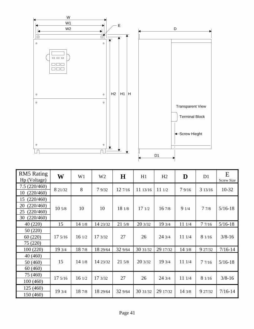
150 (460)7/16-149 27/3214 3/829 17/3230 31/3232 9/6418 29/6418 7/819 3/4
125 (460)100 (460)
3/8-168 1/1611 1/424 3/4262717 3/3216 1/217 5/1675 (460)60 (460)50 (460) 5/16-187 7/1611 1/419 3/420 3/3221 5/814 23/3214 1/81540 (460)
7/16-149 27/3214 3/829 17/3230 31/3232 9/6418 29/6418 7/819 3/4100 (220)75 (220) 60 (220) 3/8-168 1/1611 1/424 3/4262717 3/3216 1/217 5/1650 (220)
5/16-187 7/1611 1/419 3/420 3/3221 5/814 23/3214 1/81540 (220)30 (220/460)25 (220/460)20 (220/460) 5/16-187 7/89 1/416 7/817 1/218 1/8101010 5/8
15 (220/460)10 (220/460) 10-323 13/167 9/1611 1/211 13/1612 7/167 9/3288 21/327.5 (220/460)
EScrew Size
D1DH2H1HW2W1WRM5 RatingHp (Voltage)
Page 41
Transparent View
Terminal Block
D1
Screw Hieght
DW2W1W
H1 HH2
E

Specifications
230 Volt Input
+/- 5%Input Frequency FluctuationRange (Hz)
180 to 253 VInput Power Range (V)200 to 230V / 50 to 60 Hz / 3200 to 230V
50 to 60 Hz / 1 or 3Input Power (V, , Hz)0.01 to 400 HzOutput Frequency Range (Hz)
200 to 230V 3Output Voltage Rating (V) 220175145115907460463325171185Current Rating (A)7560504030252015107.55321Horsepower
RM
5-20
75
RM
5-20
60
RM
5-20
50
RM
5-20
40
RM
5-20
30
RM
5-20
25
RM
5-20
20
RM
5-20
15
RM
5-20
10
RM
5-20
07
RM
5-20
05
RM
5-20
03
RM
5-20
02
RM
5-20
01
Model Number
460 Volt Input
+/- 5%Input Frequency FluctuationRange (Hz)
323 to 506 VInput Power Range (V)380 to 460V / 50 to 60 Hz / 3 Input Power (V, , Hz)
0.01 to 400 HzOutput Frequency Range (Hz)380 to 460V 3Output Voltage (V)
2041761371108773614539302418149642.5Current Rating (A)1501251007560504030252015107.55321Horsepower
RM
5- 4
150
RM
5- 4
125
RM
5- 4
100
RM
5- 4
075
RM
5- 4
060
RM
5- 4
050
RM
5- 4
040
RM
5- 4
030
RM
5- 4
025
RM
5- 4
020
RM
5- 4
015
RM
5- 4
010
RM
5- 4
007
RM
5- 4
005
RM
5- 4
003
RM
5- 4
002
RM
5- 4
001
Model Number
Page 42

Common Specifications
Less than 1000 meters (3280 ft) (see table in section 2.1)AltitudeLess than 5.9m/sec2 (0.6G)Vibration90% Relative Humidity or lessHumidity-10C to 50C No Condensation (14F to 122F) TemperatureNon Explosive, Non Corrosive, Atmosphere
A
mbi
ent
Con
ditio
ns
When keypad displays the following.OC (Over Current)OE (Over Voltage)LE (Under Voltage)OL (Motor Overload)OLI (RM5 Inverter Overload)OH (Overheat)GF (Ground Fault)SC (Blown Fuse)PadF (Keypad Disconnected during Operation)
Diagnostics
Pro
tect
ion
Fea
ture
s
The RM. supports 1 analog meter with a selection of 3settings. (see F 044. Meter connects to FM+ and FM-)Analog Meters, Auxiliary
The RM5 supports up to 3 digital meters with a selectionof 8 settings. (see F098, F099, F100, F101. Meters plug toCNN)
Digital Meters, Auxiliary
The keypad displays 8 meter functions. (see F006)Keypad Display
Dis
play
M
eter
s
3 Programmable outputs with a selection of 11 features.(see F 058, F059, F060)Multiple Function Outputs
6 Programmable inputs with a selection of 12 features. (see F 052 to F057)Multiple Function Inputs
Activated by holding the circuit closed. (see F001)Forward & Reverse Inputs
0 to 10 VDC Voltage Reference or 4 to 20 mA Current Reference (see F002, F040, F 041)Analog Speed Reference Scale
Con
trol
F
eatu
res
Stall prevention acceleration current and level speedcurrent are independently programmable. (see F 070 andF071_
Stall Prevention
Three Voltage/Frequency Patterns (i.e. V/F pattern) Each V/F pattern is independently programmable (see F034 to F039)
Voltage Frequency Patterns
DC braking current is programmable form 0 to 150% ofRM5 current rating with dynamic braking transistor(DBT) and resistor. If DBT and resistor are not used DCbraking current is limited to 20%. (see F 075)
Braking Torque
0.1 to 3200 seconds. Free running stop set deceleration to 0 seconds.Acceleration and Deceleration Scale
150% of motor’s rating for 1 minute(see F046, F047, F048)Overload Current
0.1 HzFrequency Resolution0.01 to 400 Hz (see F092)Frequency Range
Pulse Width Modulation (PWM) to synthesize sinusoidal waveOutput Signal
Mot
orin
g
F
eatu
res
Page 43

FWDREVX1X2X3X4X5X6COM
( F 052 default: Multipul Speed Level 1)
( F 053 default: Multipul Speed Level 2)
( F 054 default: Jog)
( F 055 default: Secondary Accel & Decel Time)
( F 056 default: External Fault Signal Input)
( F 057 default: Reset)
12VVIN
GNDIIN ( F 040 & F 041 default: 4 ~ 20 mA)
( F 040 & F 041 default: 0 ~ 10 Volts)
L1
L2
L3
CircuitBreaker
Speed Reference
Y1
Y2
CME Common Emittereach colector is 48VDC / 50mA
( F 058 default: Rotation Detect)
( F 059 default:Constqant Speed Detect)
TaTbTc
FM+FM-
Analog meter terminals: F 044 default: 0 (Output Frequency)
R
S
T
MU
V
W
PE
T1
T2
T3
PR P
DYNAMIC BRAKE RESISTOR (DB)
When the DB resistor is installed, remove this jumper. A
(F 060 default: General Fault Detect)
CARLSBAD, CA. USA1-800-458-6566
Multi Speed TableMain LevelLevel 1Level 2Level 3Levels 4, 5, 6 and 7 areavailbe by programmingX3 (F 054) to 5.
X1 X2Off OffOff OnOn OffOn On
RM5Elimentary wire diagramfor open loop operation
Note: The 1, 2, 3 and 5 HP use GND in place of FM-.
0 ~ 10 volt scale, RLMAX 10K , IMAX 100 A
CN1 Digital meter plug, Serial output, Supports up to three meters.
(VREF)
IREF
This diagram is for installing the DB resitor for 1 to 5 HP.For installing the DB resistor on 7 HP and above consult the users manual.
Page
44