Danfoss Airheating.danfoss.com/PCMPDF/AIR_installation-guide_VIFKB202_hi-res.… · Installation...
24
DANFOSS HEATING Danfoss Air Installation guide for Danfoss Heating Surfaces MAKING MODERN LIVING POSSIBLE
Transcript of Danfoss Airheating.danfoss.com/PCMPDF/AIR_installation-guide_VIFKB202_hi-res.… · Installation...

DANFOSS HEATING
Danfoss AirInstallation guide for Danfoss Heating Surfaces
MAKING MODERN LIVING POSSIBLE

Index 1.0 Mounting electrical heating surfaces 1.1 About electrical pre-heating surfaces . . . . . . . . . . . . . . . . . . . . . . . . . . . . . . . . . . . . . . . . . . . . . . . . . . . 3 1.2 About electrical after heating surfaces . . . . . . . . . . . . . . . . . . . . . . . . . . . . . . . . . . . . . . . . . . . . . . . . . . 3 1.3 Positioning of an electrical heating surface . . . . . . . . . . . . . . . . . . . . . . . . . . . . . . . . . . . . . . . . . . . . . . 4 1.4 Positioning of sensors. . . . . . . . . . . . . . . . . . . . . . . . . . . . . . . . . . . . . . . . . . . . . . . . . . . . . . . . . . . . . . . . . . . 4 1.5 Electrical connection and connecting communications . . . . . . . . . . . . . . . . . . . . . . . . . . . . . . . . . . 4 1.6 System overview – one heating surface connected . . . . . . . . . . . . . . . . . . . . . . . . . . . . . . . . . . . . . . 5 1.7 System overview – two heating surfaces connected . . . . . . . . . . . . . . . . . . . . . . . . . . . . . . . . . . . . . 6 1.8 Troubleshooting table . . . . . . . . . . . . . . . . . . . . . . . . . . . . . . . . . . . . . . . . . . . . . . . . . . . . . . . . . . . . . . . . . . 7
2.0 Mounting waterborne after heating surfaces 2.1 About waterborne after heating surfaces . . . . . . . . . . . . . . . . . . . . . . . . . . . . . . . . . . . . . . . . . . . . . . . . 8 2.2 Positioning of a water heating surface . . . . . . . . . . . . . . . . . . . . . . . . . . . . . . . . . . . . . . . . . . . . . . . . . . . 8 2.3 Positioning of sensors. . . . . . . . . . . . . . . . . . . . . . . . . . . . . . . . . . . . . . . . . . . . . . . . . . . . . . . . . . . . . . . . . . . 8 2.4 Hydraulic connection of water heating surfaces . . . . . . . . . . . . . . . . . . . . . . . . . . . . . . . . . . . . . . . . . 9 2.5 Electrical connection of water heating surfaces . . . . . . . . . . . . . . . . . . . . . . . . . . . . . . . . . . . . . . . . .10 2.6 Call for heating to the central heating system. . . . . . . . . . . . . . . . . . . . . . . . . . . . . . . . . . . . . . . . . . . 11 2.7 Troubleshooting table . . . . . . . . . . . . . . . . . . . . . . . . . . . . . . . . . . . . . . . . . . . . . . . . . . . . . . . . . . . . . . . . . 11
3.0 Mounting geothermal surfaces 3.1 Before you start. . . . . . . . . . . . . . . . . . . . . . . . . . . . . . . . . . . . . . . . . . . . . . . . . . . . . . . . . . . . . . . . . . . . . . . .13 3.2 Dimensioning ground collectors . . . . . . . . . . . . . . . . . . . . . . . . . . . . . . . . . . . . . . . . . . . . . . . . . . . . . . .13 3.3 Laying ground collectors. . . . . . . . . . . . . . . . . . . . . . . . . . . . . . . . . . . . . . . . . . . . . . . . . . . . . . . . . . . . . . .14 3.4 Filling with brine. . . . . . . . . . . . . . . . . . . . . . . . . . . . . . . . . . . . . . . . . . . . . . . . . . . . . . . . . . . . . . . . . . . . . . .15 3.5 Electrical connection. . . . . . . . . . . . . . . . . . . . . . . . . . . . . . . . . . . . . . . . . . . . . . . . . . . . . . . . . . . . . . . . . . .16 3.6 Installation in duct system . . . . . . . . . . . . . . . . . . . . . . . . . . . . . . . . . . . . . . . . . . . . . . . . . . . . . . . . . . . . .17 3.7 Positioning of sensors. . . . . . . . . . . . . . . . . . . . . . . . . . . . . . . . . . . . . . . . . . . . . . . . . . . . . . . . . . . . . . . . . .17 3.8 Troubleshooting table . . . . . . . . . . . . . . . . . . . . . . . . . . . . . . . . . . . . . . . . . . . . . . . . . . . . . . . . . . . . . . . . .18
4.0 Technical data 4.1 Technical data – water heating surface W-AH 250 & geothermal surface Geo 250 . . . . . . . .19 4.2 Technical data – electrical heating surfaces EL-PH & EL-AH . . . . . . . . . . . . . . . . . . . . . . . . . . . . . .20
Installation The Danfoss Air system – Heating surfaces
2 VIFKB202

1.1About electricalpre-heating surfaces
The electrical pre-heating surface is built into the duct system on the outdoor air side.The aim of the pre-heating surface is to ensure that the temperature in the system remains above freezing, which allows it to always guarantee the required balance between the air intake and extraction volumes.
Note: A system without a pre-heating surface will gradually reduce the air intake volumes during long term operation at outside tempera-
tures below -3°C in order to prevent freezing. In an average house this is an excellent solution, but in extremely airtight buildings (low energy constructions), the imbalance could cause a non-desirable negative pressure inside the house. Installing a pre-heating surface is therefore recommended here.
Note! The electrical heating surface must be installed by a certified electrician.
The electrical After heating surface is built into the duct system, on the air intake side. The purpose of the After heating surface is to slightly raise the supply air temperature, to prevent discomfort in room where supply air is distributed.
Note: The electrical heating surface must be installed by a certified electrician.
Installation 1.0 Mounting electrical heating surfaces
1.2About electricalafter heating surfaces
Overview table, electrical pre-heating surface
50 cm 50 cm
230V, 50 Hz
A
B
C
D
EFG
H
I
J
K
A Extract air G Supply cable to the surfaceB Supply air H Supply cable to automatic functionC Outdoor air I Communication cable HRV unit -> external controller.
D Exhaust air J Post-heating (to be insulated with mm glass/mineral wool).
E Sensor placed before surface K External controller (must not be insulated)
F Sensor placed after surface
Overview table, electrical after heating surfaces
Isoleres med 50mm sten- eller glasuld
50 cm 50 cm
230V, 50 Hz
A
B
C
D
EFG
H
I
J
K
A Extract air G Supply cable to the surfaceB Supply air H Supply cable to automatic functionC Outdoor air I Communication cable HRV unit -> external controller.
D Exhaust air J Post-heating (to be insulated with mm glass/mineral wool).
E Sensor placed before surface K External controller (must not be insulated)
F Sensor placed after surface
3VIFKB202

• The heating surface must be placed at a minimum distance of twice the diameter of the heating surface, to the nearest obstacle (be it bends, external filters or the unit itself).
• The connection box on the actual heating surface should face upwards or horizontally. It must NOT face downwards.
• The heating surface MUST be insulated with non-flammable insulating material.
• Note: The cover of the electrical surface’s external controller must NOT be insulated, but must remain visible so that the manual over-heating protection can be deactivated if this is triggered unexpectedly.
• The heating surface must be placed a minimum of 30 mm from any wooden building components.
• Make sure that the surface faces in the correct direction in relation to the direction of airflow in the system. The arrow on the heating surface must match the direction of airflow in the system.
min 2 x Ø min 2 x Ø
• The two factory mounted PT-1000 sensors must be placed in the duct system 50 cm in front of and 50 cm behind the surface.
• Important! Make sure that the sensors show where they must be placed, either in front of or behind the surface. If the sensors face the wrong way, the required operations cannot be achieved.
• Drill Ø8 mm holes in the duct and install the rubber sleeves supplied, then lead the sensors into the duct. Fix the sensors to the pipe using duct tape and insulate together with the rest of the duct system and heating surface.
Seen in direction of airflow
45 mm
Rubber sleeve.
Insulation.
1.5Electrical connectionand connectingcommunications
The electrical connection can be divided into three steps:
1. The mains lead from the supplied external controller (marked “supply voltage 230 V, 50 Hz”) is connected to the mains power, using a suitable junction box. We recommend that the heating surfaces be supplied from a separate group.
2. The power cable from the external controller (marked “to heating surface”) is connected to
the electrical heating surface, cf. electrical diagram.
3. The supply cable for the heating surface, is fed through the pre-punched holes in the heating surface junction box. A cable gland must be used to provide strain relief.
4. The communication cable is mounted between the external controller and the ventilation system’s serial input (also see the following pages).
Note! The control box must not be insulated
Installation 1.0 Mounting electrical heating surfaces
Electrical heating surfaces
Solid state relæ
3 4 5 6
Gråt modbus stik, set fra tilslutningsside
20 21
N L PE
+-
21
24 26
N
L1
PE
Klemme 1: OrangeKlemme 2: Blå (+modstand)Klemme 3: Hvid/blå (+modstand)Klemme 4: Tom
OBS:120 Ohms modstand mellem klemme 2 & 3
1. PT 1000 sensor, behind surface (control sensor).
2. PT 1000 sensor in front of the surface.
3. Communication cable between the HRV unit and mounting case (10 m, twisted pair, 2 pairs + display)
4. The power cable, 230 V, 50 Hz, should be connected to a separate 10 A group (3 m, 3G1.5).
5. Heating surface connection (3 m 3G1.5).6. Over-heating thermostat with automatic re-closure (70°C).
7. The over-heating thermostat with manual closure (120°C).
8. Element.
1.3Positioning of anelectrical heating surface
1.4Positioning of sensors
4 VIFKB202

Installation 1.0 Mounting electrical heating surfaces
Unit CCM Z-wave Air Dial
Mounting sequence – carried out on the serial socket in the ventilation unit
1.
2.
3.
Serial cables and twisted together in pairs (same colour).
Crimp-on ferrules can be used after twisting the two pairs (recommended)
The twisted pairs are inserted into the unit connector, see point 4 for close up of collector
4.
ab
cd
ef
5.
Colour code:a. White/orangeb Orangec. Blackd. White/bluee. Bluef. Remove jumper fitted over terminals 5 and 6
Insert the connector into the unit. After a maximum of four minutes, the system’s Air Dial will recognise the connected heating surface and automatically register it with the system.
Serial cable from CCM to the unit.
Serial cable from the heating surface control to the unit.
External controller.
1.6System overview– one heating surface connected
5VIFKB202

Installation 1.0 Mounting electrical heating surfaces
Unit CCM Z-wave Air Dial
Mounting sequence
1.
2.
3.
ab
cd
ef
Heating surface external controller 1 is mounted as shown on page 5.Note: the termination resistance on heating surface 1 must be removed!
Colour code:Cl. 1: Orange/OrangeCl. 2: Blue/BlueCl. 3: White blue/white blueCl. 4: Empty
Colour code:a. White/orangeb Orangec. Blackd. White/bluee. Bluef. Remove jumper fitted over terminals 5 and 6.
4.
Insert the connector into the unit. After a maximum of four minutes, the system’s Air Dial will recognise the connected heating surface and automatically register it with the system.
Serial cable from CCM to the unit.
Serial cable from heating surface external controller 1 to the unit.
Serial cable from heating surface external controller 2 to control 1.
Heating controller 1,without termination resistance.
Heating surface external controller 2,with termination resistance.
1.7System overview– two heating surfaces connected
6 VIFKB202
Installation 1.0 Mounting electrical heating surfaces
Symptom Possible faults Solution
The surface does not register automatically after connection of power to the control.
It can take up to four minutes after a surface is connected before it is included in the network.
Wait four minutes and check whether any new units have been added to the system on the Air Dial remote control.
A communication cable has not been connected correctly.
Check that the communication cables are mounted correctly and that the colour codes between the individual cables are as shown in this guide.
The termination resistance is not correctly positioned for the last unit in the chain.
Make sure that a termination resistance is ONLY mounted on the last unit in the system.
The surface cuts out because of the over-heating protection.
Flow across the surface is too low.
Check for air passages in the system. This type of fault is often due to insulation material residue in the duct system. Once the fault has been found and corrected, the heating surface’s over-heating protection is re-set manually. This is done using the red button on the top of the heating surface. Power to the actual ventilation system is then switched off briefly, after which operations can be re-started.
Duct sensors mounted incorrectly/wrong way round.
Check the label on the temperature sensors; sensor labels show where the sensor should be placed in the system in relation to the heating surface.
A component in the duct system is mounted too close to the heating surface (bend, filter, reduction, etc.).
The component that is disrupting the airflow across the surface must be moved so that the heating surface is covered evenly.
Fuses blown in main power supply
The phase is overloaded. Supply the heating surface from a separate 10A fused group.
Unpleasant draughts/smells Dust coating on the heating surface
It can be expected, that an electrical heating surface will give off a “slightly burnt smell” when first used (or after a long period where it has not been in use). This is a short-term issue and will disappear in a short time. The smell is due to small particles of dust on the surface of the heating surface getting hot.
The surface does not give off any heat
The surface’s over-heating protection has been triggered.
Check for any foreign objects in the duct system. Once you have found and corrected the fault, the heating surface’s over-heating protection must be re-set manually, which is done using the red button on the top of the heating surface. Power to the actual ventilation system will then be disconnected briefly, after which operation can be re-started.
The fuses in the surface’s supply group have blown.
Change the fuses.
1.8Troubleshooting table
7VIFKB202
2.1About waterborneafter heating surfaces
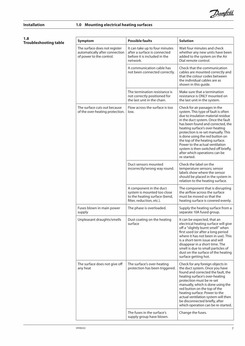
The waterborne after heating surfaces are installed in the duct system on the air intake side. The purpose of the after heating surface is to give intake air a lower rise in temperature to ensure against disruption in comfort or draughts in the rooms where air is taken in.
The water heating surface is connected to the building’s central heating system, with both flow and return. The heating surface has inbuilt protection against frost burst.
Note: Flow and return to the surface must be insulated.
Installation 2.0 Mounting waterborne after heating surfaces
• The heating surface must be placed at a minimum distance of 500 mm from any components in the duct system (bends, any external filters and the actual unit).
• The heating surface is fitted on the supply air side, after the ventilation unit.
• The heating surface is insulated on delivery and does not require any further insulation.
• Take care that the surface is facing the correct direction in relation to the direction of airflow in the system. The arrow on the heating surface must match the direction of air flow in the system.
• The heating surface is designed to be mounted horizontally, but can also be mounted vertically if the heating surface is adequately supported, and if the direction of air flow is “upwards”.
Overview table, waterborne after heating surface
+
A
B
C
D
EF
A Extract air D Exhaust airB Supply air E Sensor T1C Outdoor air F Sensor T2
2.2Positioning of a water heating surface
• The two factory mounted PT-1000 sensors must be placed in the duct system 50 cm in front of and 50 cm behind the surface.
• Important! Make sure that the sensors show where they must be placed, either in front of or behind the surface. If the sensors face the wrong way, the required operations cannot be achieved.
• Drill Ø8 mm holes in the duct and install the rubber sleeves supplied, then lead the sensors into the duct. Fix the sensors to the pipe using ventilation tape and insulate together with the rest of the duct system and heating surface.
Set with direction of airflow
45 mm
Rubber sleeve.
Insulation.
2.3Positioning of sensors
8 VIFKB202
Installation 2.0 Mounting waterborne after heating surfaces
2.4Hydraulic connection of water after heating surfaces
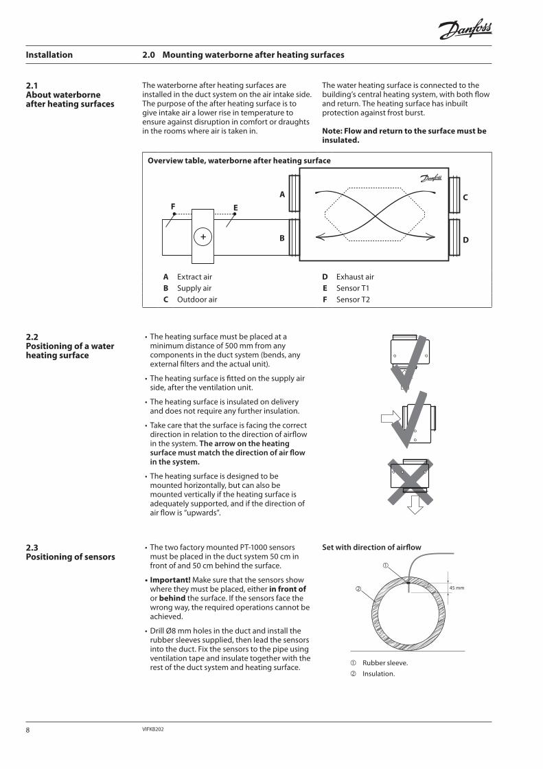
• The water heating surface is connected as shown in the below connection diagram (3/8” nipple).
• On delivery, the water heating surface’s control valve is fully open and therefore ready for filling, even when switched off.
• We recommend that you install a dirt trap in the system, and that the shut-off valves be mounted close to the surface to make any subsequent servicing requirements easier.
• An air-bleed screw must be mounted at the highest point in the system.
• Fill the system with water and bleed out the air; the surface is then ready for use.
• Flow and return to the surface should be insulated safely with regard to the frost bursting risk.
Connection diagram, waterborne after heating surfaces
HVAC delivery supplied by others Danfoss delivery
M
A
A
B
C
D
E
F
GHI
J
230 V50 Hz
A Shut-off valves (recommended) F Any calls for heating are set up with a potential-free relay
B PT 1000 sensors are mounted in the duct as in the drawing
G Heating surface.
C Air-bleeding screw (recommended) H Control value with motor actuator
D Circulation pump (central heating system) I Dirt trap
E Expansion tank (normally already installed in the central heating system)
J Central heating system– maximum flow temperature 85°C– minimum differential pressure 0.2 bar– maximum differential pressure 4.0 bar– maximum pressure level PN 6
9VIFKB202
Installation 2.0 Mounting waterborne after heating surfaces
2.5Electrical connection of water heating surfaces
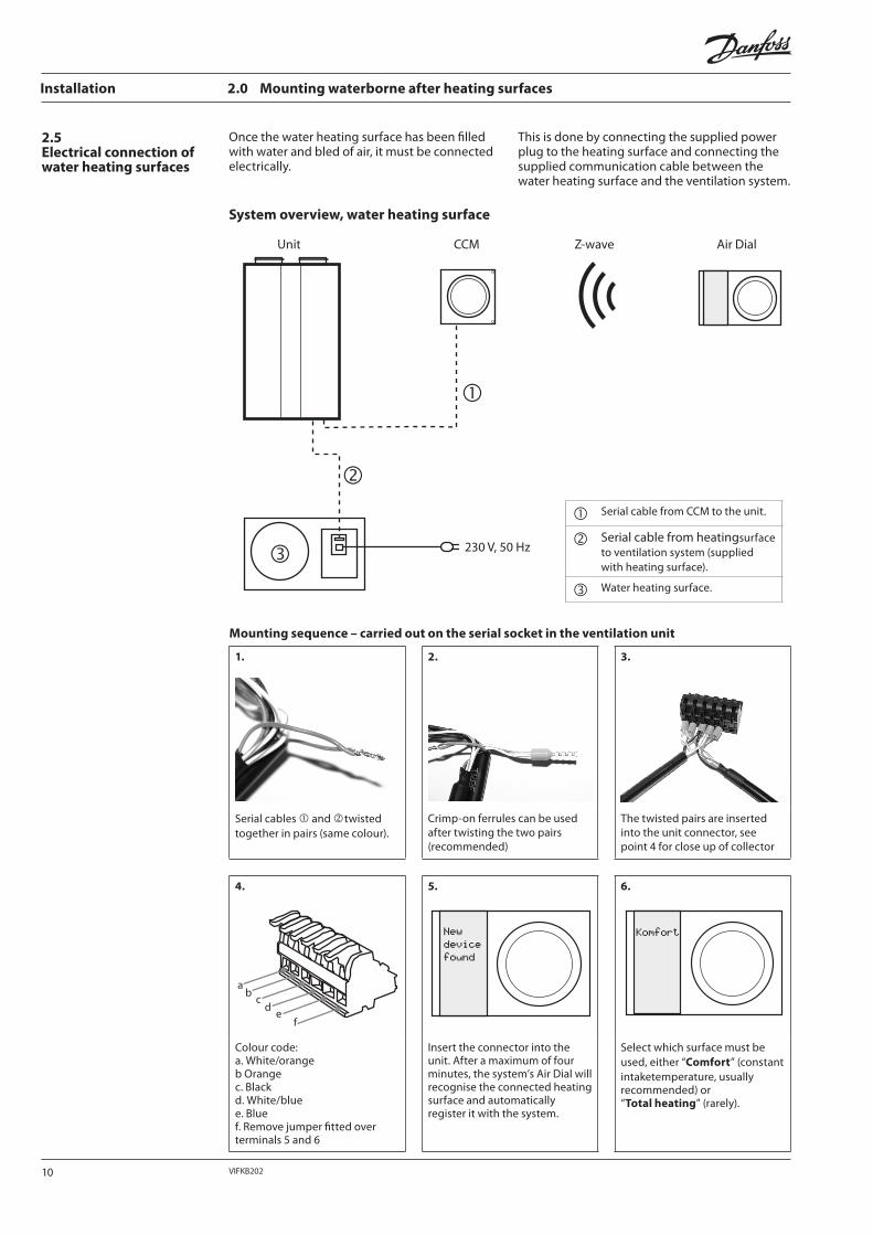
Once the water heating surface has been filled with water and bled of air, it must be connected electrically.
This is done by connecting the supplied power plug to the heating surface and connecting the supplied communication cable between the water heating surface and the ventilation system.
System overview, water heating surface
Unit CCM Z-wave Air Dial
230 V, 50 Hz
Mounting sequence – carried out on the serial socket in the ventilation unit
1.
2.
3.
Serial cables and twisted together in pairs (same colour).
Crimp-on ferrules can be used after twisting the two pairs (recommended)
The twisted pairs are inserted into the unit connector, see point 4 for close up of collector
4.
ab
cd
ef
5.
6.
Colour code:a. White/orangeb Orangec. Blackd. White/bluee. Bluef. Remove jumper fitted over terminals 5 and 6
Insert the connector into the unit. After a maximum of four minutes, the system’s Air Dial will recognise the connected heating surface and automatically register it with the system.
Select which surface must be used, either “Comfort” (constant intaketemperature, usually recommended) or“Total heating” (rarely).
Serial cable from CCM to the unit.
Serial cable from heatingsurface to ventilation system (supplied with heating surface).
Water heating surface.
10 VIFKB202
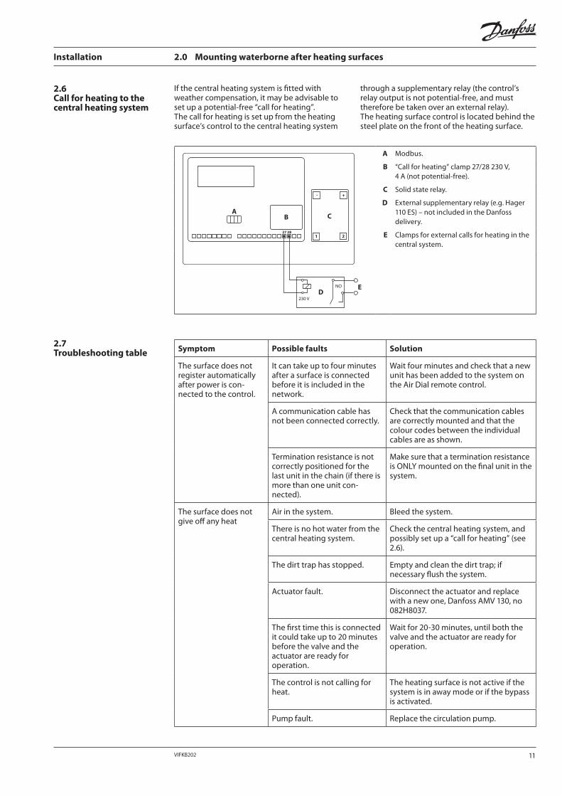
If the central heating system is fitted with weather compensation, it may be advisable to set up a potential-free “call for heating”. The call for heating is set up from the heating surface’s control to the central heating system
through a supplementary relay (the control’s relay output is not potential-free, and must therefore be taken over an external relay).The heating surface control is located behind the steel plate on the front of the heating surface.
+-
2127 28
NO
230 V
AB C
DE
A Modbus.
B “Call for heating” clamp 27/28 230 V,4 A (not potential-free).
C Solid state relay.
D External supplementary relay (e.g. Hager 110 ES) – not included in the Danfoss delivery.
E Clamps for external calls for heating in the central system.
2.7Troubleshooting table
Installation 2.0 Mounting waterborne after heating surfaces
2.6Call for heating to the central heating system
Symptom Possible faults Solution
The surface does not register automatically after power is con-nected to the control.
It can take up to four minutes after a surface is connected before it is included in the network.
Wait four minutes and check that a new unit has been added to the system on the Air Dial remote control.
A communication cable has not been connected correctly.
Check that the communication cables are correctly mounted and that the colour codes between the individual cables are as shown.
Termination resistance is not correctly positioned for the last unit in the chain (if there is more than one unit con-nected).
Make sure that a termination resistance is ONLY mounted on the final unit in the system.
The surface does not give off any heat
Air in the system. Bleed the system.
There is no hot water from the central heating system.
Check the central heating system, and possibly set up a “call for heating” (see 2.6).
The dirt trap has stopped. Empty and clean the dirt trap; if necessary flush the system.
Actuator fault. Disconnect the actuator and replace with a new one, Danfoss AMV 130, no 082H8037.
The first time this is connected it could take up to 20 minutes before the valve and the actuator are ready for operation.
Wait for 20-30 minutes, until both the valve and the actuator are ready for operation.
The control is not calling for heat.
The heating surface is not active if the system is in away mode or if the bypass is activated.
Pump fault. Replace the circulation pump.
11VIFKB202
Installation 2.0 Mounting waterborne after heating surfaces
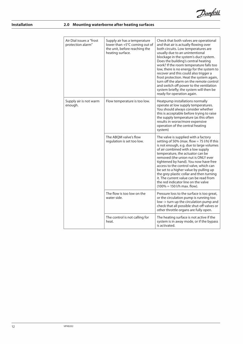
Air Dial issues a “frost protection alarm”
Supply air has a temperature lower than +5°C coming out of the unit, before reaching the heating surface.
Check that both valves are operational and that air is actually flowing over both circuits. Low temperatures are usually due to an unintentional blockage in the system’s duct system. Does the building’s central heating work? If the room temperature falls too low, there is no energy for the system to recover and this could also trigger a frost protection. Heat the system again, turn off the alarm on the remote control and switch off power to the ventilation system briefly; the system will then be ready for operation again.
Supply air is not warm enough.
Flow temperature is too low. Heatpump installations normally operate at low supply temperatures. You should always consider whether this is acceptable before trying to raise the supply temperature (as this often results in worse/more expensive operation of the central heating system)
The ABQM valve’s flow regulation is set too low.
The valve is supplied with a factory setting of 50% (max. flow = 75 l/h) If this is not enough, e.g. due to large volumes of air combined with a low supply temperature, the actuator can be removed (the union nut is ONLY ever tightened by hand). You now have free access to the control valve, which can be set to a higher value by pulling up the grey plastic collar and then turning it. The current value can be read from the red indicator line on the valve (100% = 150 l/h max. flow).
The flow is too low on the water side.
Pressure loss to the surface is too great, or the circulation pump is running too low -> turn up the circulation pump and check that all possible shut-off valves or other throttle organs are fully open.
The control is not calling for heat.
The heating surface is not active if the system is in away mode, or if the bypass is activated.
12 VIFKB202

Installation 3.0 Mounting geothermal surfaces
3.1Before you start • Before starting the digging work you will need to obtain any necessary permits from the local
building authorities! We recommend you contact a groundworks contractor and get a full quote for the laying of ground heating pipes and leading the pipes into the building.
• The installation must be pressure tested by an authorised installer before commissioning.
• Find all relevant maps and information on the digging area and check the planned location carefully so that no damage is done to other underground installations (water, electricity, gas, sewage, etc.).
You can use the table below to help you decide how many metres of pipe you need to lay for the installation in question. You need to know the volume of air and the soil type in order to estimate the pipe length required.The sandier and drier the soil is, the less heat can be drawn from the ground, which is why more pipes need to be laid in this type of soil than in more normal (damper) soil.
If you are in any doubt about the type of soil you have, you should allow for sandy soil as the extra cost of laying a couple of additional metres will not make any significant difference to the total installation costs.
The volume of air for which you should allow for is either the nominal air volume required, or a slightly higher volume of air to allow for a better cooling performance in the summer.
Required pipe lengths
[m3/h]
B
[m]
A200
175
150
125
100
75
50
25
00 50 100 150 200 250 300 350 400
A: Dry sandy soil (15 W/m2)B: Normal soil (20-30 W/m2)
3.2Dimensioning ground collectors
13VIFKB202
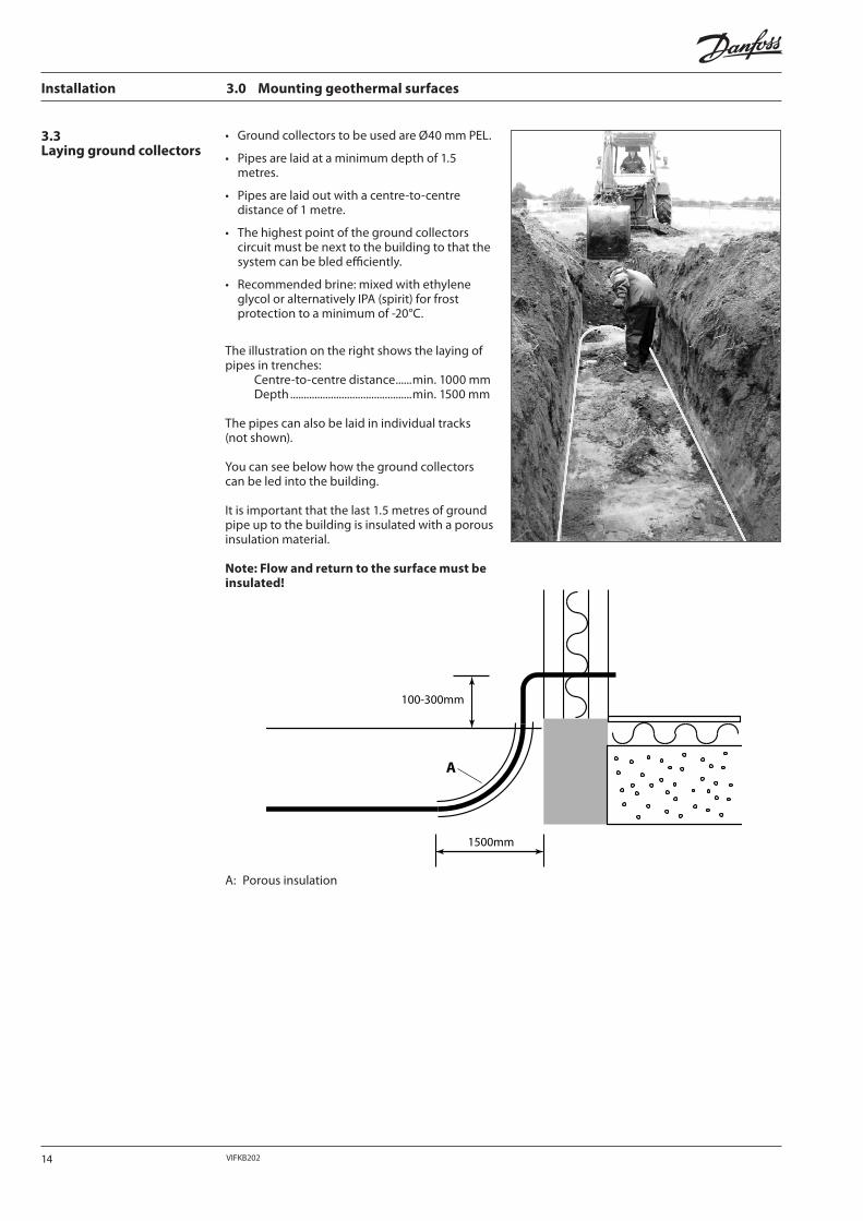
• Ground collectors to be used are Ø40 mm PEL.
• Pipes are laid at a minimum depth of 1.5 metres.
• Pipes are laid out with a centre-to-centre distance of 1 metre.
• The highest point of the ground collectors circuit must be next to the building to that the system can be bled efficiently.
• Recommended brine: mixed with ethylene glycol or alternatively IPA (spirit) for frost protection to a minimum of -20°C.
The illustration on the right shows the laying ofpipes in trenches: Centre-to-centre distance ......min. 1000 mm Depth .............................................min. 1500 mm
The pipes can also be laid in individual tracks (not shown).
You can see below how the ground collectors can be led into the building.
It is important that the last 1.5 metres of ground pipe up to the building is insulated with a porous insulation material.
Note: Flow and return to the surface must be insulated!
Installation 3.0 Mounting geothermal surfaces
100-300mm
1500mm
A
A: Porous insulation
3.3Laying ground collectors
14 VIFKB202
Installation 3.0 Mounting geothermal surfaces
+/-A
B C
D
E F
G
H1H2
I
J
K
L MN
O
P
Q
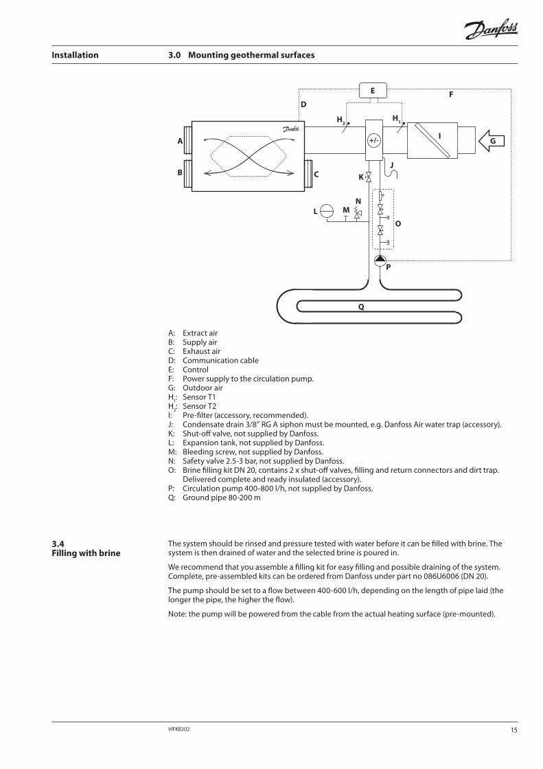
A: Extract airB: Supply airC: Exhaust airD: Communication cableE: ControlF: Power supply to the circulation pump.G: Outdoor airH
1: Sensor T1
H2: Sensor T2
I: Pre-filter (accessory, recommended).J: Condensate drain 3/8” RG A siphon must be mounted, e.g. Danfoss Air water trap (accessory).K: Shut-off valve, not supplied by Danfoss.L: Expansion tank, not supplied by Danfoss.M: Bleeding screw, not supplied by Danfoss.N: Safety valve 2.5-3 bar, not supplied by Danfoss.O: Brine filling kit DN 20, contains 2 x shut-off valves, filling and return connectors and dirt trap.
Delivered complete and ready insulated (accessory).P: Circulation pump 400-800 l/h, not supplied by Danfoss.Q: Ground pipe 80-200 m
The system should be rinsed and pressure tested with water before it can be filled with brine. The system is then drained of water and the selected brine is poured in.
We recommend that you assemble a filling kit for easy filling and possible draining of the system. Complete, pre-assembled kits can be ordered from Danfoss under part no 086U6006 (DN 20).
The pump should be set to a flow between 400-600 l/h, depending on the length of pipe laid (the longer the pipe, the higher the flow).
Note: the pump will be powered from the cable from the actual heating surface (pre-mounted).
3.4Filling with brine
15VIFKB202
Installation 3.0 Mounting geothermal surfaces
3.5Electrical connection
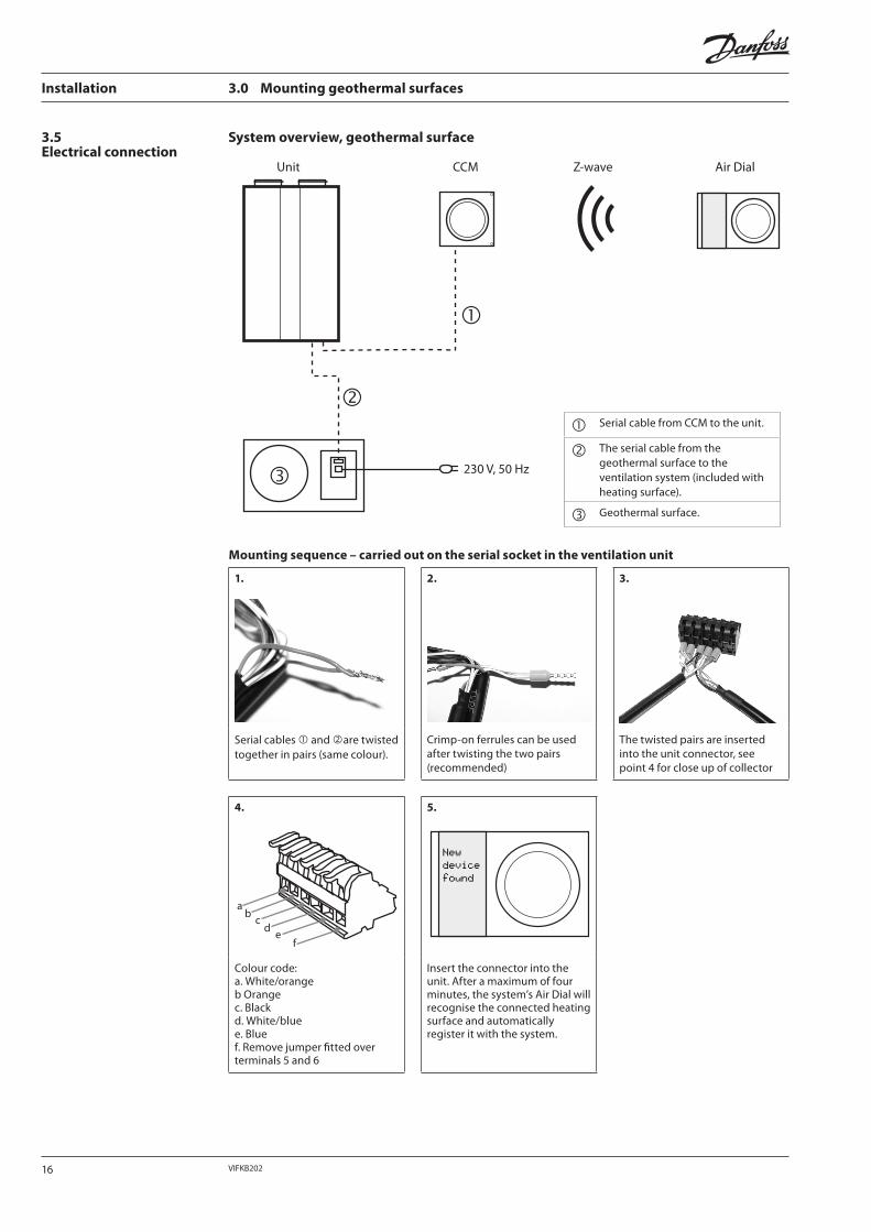
System overview, geothermal surface
Unit CCM Z-wave Air Dial
230 V, 50 Hz
Mounting sequence – carried out on the serial socket in the ventilation unit
1.
2.
3.
Serial cables and are twisted together in pairs (same colour).
Crimp-on ferrules can be used after twisting the two pairs (recommended)
The twisted pairs are inserted into the unit connector, see point 4 for close up of collector
4.
ab
cd
ef
5.
Colour code:a. White/orangeb Orangec. Blackd. White/bluee. Bluef. Remove jumper fitted over terminals 5 and 6
Insert the connector into the unit. After a maximum of four minutes, the system’s Air Dial will recognise the connected heating surface and automatically register it with the system.
Serial cable from CCM to the unit.
The serial cable from the geothermal surface to the ventilation system (included with heating surface).
Geothermal surface.
16 VIFKB202

3.6Installation in duct system
Installation 3.0 Mounting geothermal surfaces
• The surface is placed at a minimum distance of 500 mm from any of the components in the duct system (bends, filters and the unit itself).
• The surface is placed on the outdoor air side, before the ventilation unit.
• The surface supplied is already insulated and does not require any further insulation.
• Make sure that the surface faces in the correct direction in relation to the direction of airflow in the system. The arrow on the surface must match the direction of airflow in the system.
• To protect the surface from dirt, fit a Danfoss filter box type FBDU before the geothermal surface.
• The geothermal surface is designed to be mounted horizontally and may ONLY be mounted horizontally in relation to the condensate drain. The geothermal surface must be completely horizontal – check with a spirit level.
• A siphon trap must be mounted to the condensate drain, see illustration.
3.7Positioning of sensors
• The two factory mounted PT-1000 sensors must be placed in the duct system 50 cm in front of and 50 cm behind the surface.
• Important! The two sensors are labelled as to indicate their proper positioning in relation to the geothermal surface, either before or after the geothemal surface. If not placed correctly the system will malfunction.
• Drill Ø8 mm holes in the duct and install the rubber sleeves supplied, then lead the sensors into the duct. Fix the sensors to the pipe using duct tape and insulate together with the rest of the duct system and heating surface.
Set with direction of airflow
45 mm
Rubber sleeve.
Insulation.
17VIFKB202
Installation 3.0 Mounting geothermal surfaces
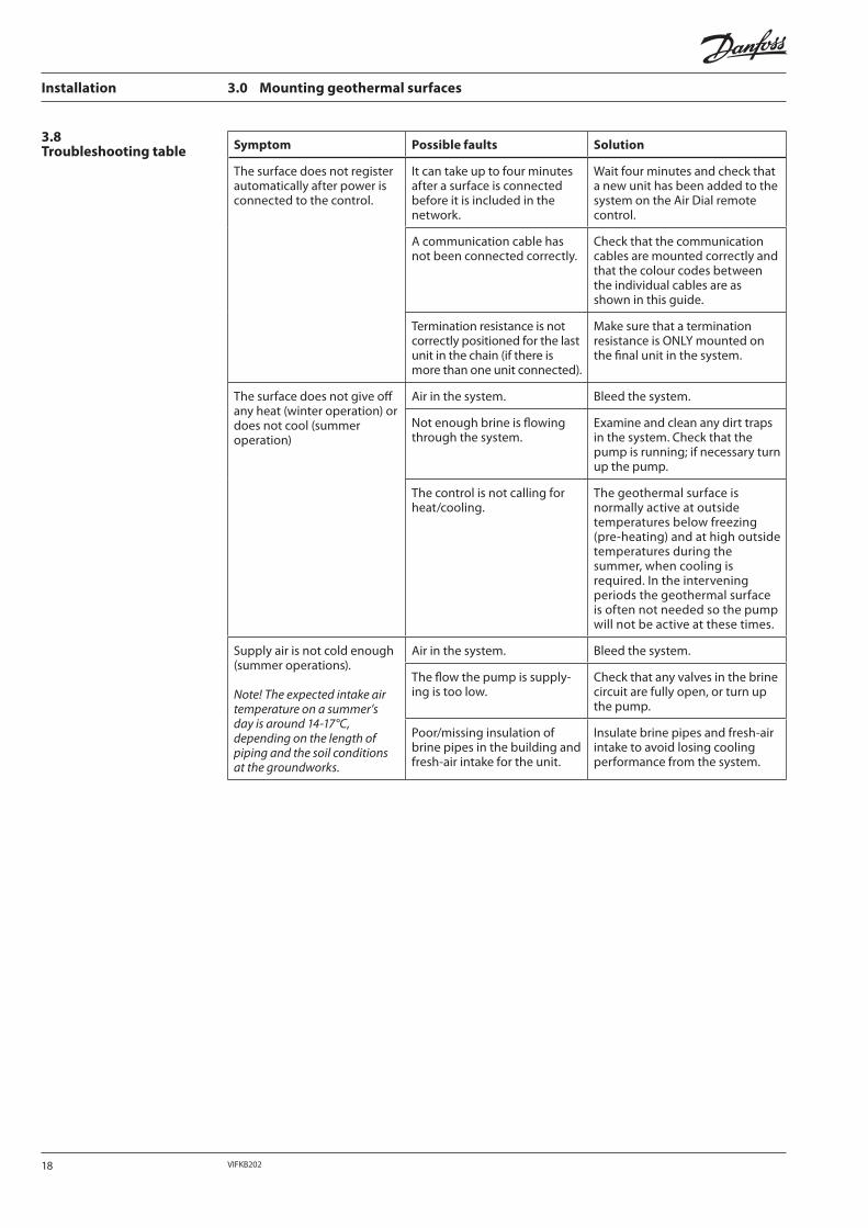
Symptom Possible faults Solution
The surface does not register automatically after power is connected to the control.
It can take up to four minutes after a surface is connected before it is included in the network.
Wait four minutes and check that a new unit has been added to the system on the Air Dial remote control.
A communication cable has not been connected correctly.
Check that the communication cables are mounted correctly and that the colour codes between the individual cables are as shown in this guide.
Termination resistance is not correctly positioned for the last unit in the chain (if there is more than one unit connected).
Make sure that a termination resistance is ONLY mounted on the final unit in the system.
The surface does not give off any heat (winter operation) or does not cool (summer operation)
Air in the system. Bleed the system.
Not enough brine is flowing through the system.
Examine and clean any dirt traps in the system. Check that the pump is running; if necessary turn up the pump.
The control is not calling for heat/cooling.
The geothermal surface is normally active at outside temperatures below freezing (pre-heating) and at high outside temperatures during the summer, when cooling is required. In the intervening periods the geothermal surface is often not needed so the pump will not be active at these times.
Supply air is not cold enough (summer operations).
Note! The expected intake air temperature on a summer’s day is around 14-17°C, depending on the length of piping and the soil conditions at the groundworks.
Air in the system. Bleed the system.
The flow the pump is supply-ing is too low.
Check that any valves in the brine circuit are fully open, or turn up the pump.
Poor/missing insulation of brine pipes in the building and fresh-air intake for the unit.
Insulate brine pipes and fresh-air intake to avoid losing cooling performance from the system.
3.8Troubleshooting table
18 VIFKB202

Installation 4.0 Technical data
4.1Technical data• Water heating surface
W-AH 250• Geothermal surface Geo
250
Dimensions, L x W x H 600 x 250 x 335 mm
Weight 6.6 kg
Connection, air Ø250
Connection, water 3/8” RG, nipple
Box Highly insulated, fire-resistant EPS shell (U-factor 0.8)
Max. heating surface (400 m3/h, temp. 70/40/20°) 2,350 W
Installation Horizontal
Max. water flow 150 l/h
Pressure loss curve for the air side, water heating surface W-AH 250 & geothermal surface Geo 250
25 50 75 100 125 150 175 200 250 275 300 325 350 3750 400 425 450 475 500
Flow[m3/h]
[Pa]
5
10
15
20
25
30
35
40
45
50
55
60
65
70
Pressure loss curve for the water/brine side, water heating surface W-AH 250 & geothermal surface Geo 250
Flow [l/h] 100 200 300 400 500 600 700 800
70
60
50
40
30
20
10
[KPa]
Power output curve for the air side– water heating surface
[W]
1
2
3
4
8
7
6
5
0 50 100 150 200 250 300 350 400 450Flow [m3/h]
3400
3000
2600
2200
1800
1400
1000
600
200
70/40/20
50/40/20
19VIFKB202
Installation 4.0 Technical data
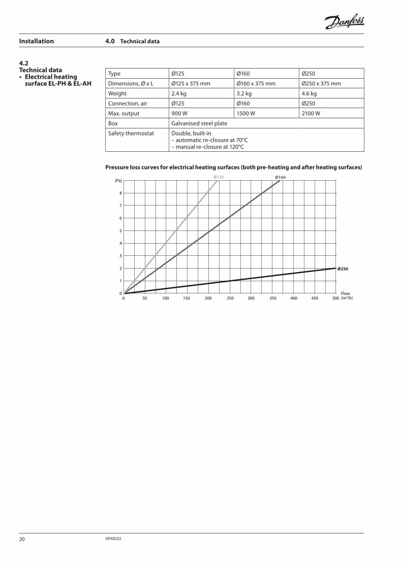
Type Ø125 Ø160 Ø250
Dimensions, Ø x L Ø125 x 375 mm Ø160 x 375 mm Ø250 x 375 mm
Weight 2.4 kg 3.2 kg 4.6 kg
Connection, air Ø125 Ø160 Ø250
Max. output 900 W 1500 W 2100 W
Box Galvanised steel plate
Safety thermostat Double, built-in– automatic re-closure at 70°C– manual re-closure at 120°C
Pressure loss curves for electrical heating surfaces (both pre-heating and after heating surfaces)
Flow[m3/h]
Ø250
Ø125 Ø160[Pa]
8
7
6
5
4
3
2
1
00 50 100 150 200 250 300 350 400 450 500
4.2Technical data• Electrical heating
surface EL-PH & EL-AH
20 VIFKB202

Installation The Danfoss Air System – Heating surfaces
21VIFKB202

Installation The Danfoss Air System – Heating surfaces
22 VIFKB202

Installation The Danfoss Air System – Heating surfaces
23VIFKB202
Installation The Danfoss Air System – Heating surfaces
www.danfoss.comVIFKB202
For generations now, Danfoss has been delivering solutions used in all aspects of heating and cooling, such as valves, thermostats, pumps and highly advanced control systems. The Danfoss Group consists of a global network
of sales companies, agents and distributors, and Danfoss products are sold, serviced and valued around the world. Danfoss products also play an important role when it comes to creating optimal indoor climate and comfort.
This has always been our legacy, and the new Danfoss Air system is set to carry on this proud tradition.
Danfoss A/SUlvehavej 61DK-7100 VejleDenmark
Tel. +45 88 85 00Fax +45 74 88 86 [email protected]